JP6545723B2 - Intravascular thromboembolism removal device having multiple clot engaging elements - Google Patents
Intravascular thromboembolism removal device having multiple clot engaging elements Download PDFInfo
- Publication number
- JP6545723B2 JP6545723B2 JP2016573675A JP2016573675A JP6545723B2 JP 6545723 B2 JP6545723 B2 JP 6545723B2 JP 2016573675 A JP2016573675 A JP 2016573675A JP 2016573675 A JP2016573675 A JP 2016573675A JP 6545723 B2 JP6545723 B2 JP 6545723B2
- Authority
- JP
- Japan
- Prior art keywords
- engagement
- wire
- elements
- proximal
- engagement elements
- Prior art date
- Legal status (The legal status is an assumption and is not a legal conclusion. Google has not performed a legal analysis and makes no representation as to the accuracy of the status listed.)
- Active
Links
- 0 *C1C=C=CCC1 Chemical compound *C1C=C=CCC1 0.000 description 1
- NRAJTVVKIPWPOL-UHFFFAOYSA-N CC(C1)C2C(C)C(C(C)C(C(C)C3)C4C3C3C5C6C(C78)C9C%10C(C%11)CC(CC%12)C9C%12C6C3)C3C4C5C7C4C56C8C%10C%11(CC7)C7C5CC6C1C2C34 Chemical compound CC(C1)C2C(C)C(C(C)C(C(C)C3)C4C3C3C5C6C(C78)C9C%10C(C%11)CC(CC%12)C9C%12C6C3)C3C4C5C7C4C56C8C%10C%11(CC7)C7C5CC6C1C2C34 NRAJTVVKIPWPOL-UHFFFAOYSA-N 0.000 description 1
Images


Classifications
-
- A—HUMAN NECESSITIES
- A61—MEDICAL OR VETERINARY SCIENCE; HYGIENE
- A61B—DIAGNOSIS; SURGERY; IDENTIFICATION
- A61B17/00—Surgical instruments, devices or methods, e.g. tourniquets
- A61B17/22—Implements for squeezing-off ulcers or the like on the inside of inner organs of the body; Implements for scraping-out cavities of body organs, e.g. bones; Calculus removers; Calculus smashing apparatus; Apparatus for removing obstructions in blood vessels, not otherwise provided for
- A61B17/221—Gripping devices in the form of loops or baskets for gripping calculi or similar types of obstructions
- A61B2017/2212—Gripping devices in the form of loops or baskets for gripping calculi or similar types of obstructions having a closed distal end, e.g. a loop
-
- A—HUMAN NECESSITIES
- A61—MEDICAL OR VETERINARY SCIENCE; HYGIENE
- A61B—DIAGNOSIS; SURGERY; IDENTIFICATION
- A61B17/00—Surgical instruments, devices or methods, e.g. tourniquets
- A61B17/22—Implements for squeezing-off ulcers or the like on the inside of inner organs of the body; Implements for scraping-out cavities of body organs, e.g. bones; Calculus removers; Calculus smashing apparatus; Apparatus for removing obstructions in blood vessels, not otherwise provided for
- A61B17/221—Gripping devices in the form of loops or baskets for gripping calculi or similar types of obstructions
- A61B2017/2215—Gripping devices in the form of loops or baskets for gripping calculi or similar types of obstructions having an open distal end
Landscapes
- Health & Medical Sciences (AREA)
- Surgery (AREA)
- Life Sciences & Earth Sciences (AREA)
- Heart & Thoracic Surgery (AREA)
- Nuclear Medicine, Radiotherapy & Molecular Imaging (AREA)
- Vascular Medicine (AREA)
- Engineering & Computer Science (AREA)
- Biomedical Technology (AREA)
- Medical Informatics (AREA)
- Molecular Biology (AREA)
- Animal Behavior & Ethology (AREA)
- General Health & Medical Sciences (AREA)
- Public Health (AREA)
- Veterinary Medicine (AREA)
- Orthopedic Medicine & Surgery (AREA)
- Surgical Instruments (AREA)
Description
本開示は、一般に、血液血管などの体腔内で使用されるデバイスおよびそれを使用する方法に関する。 The present disclosure relates generally to devices used in body cavities such as blood vessels and methods of using the same.
さまざまな病状が、少なくとも一部は、血液血管の封鎖すなわち閉塞または血塊によって引き起こされ得る。限定するものではないが、そのような状態のよく知られている例としては、卒中がある。他のそのような状態には、心筋梗塞、四肢虚血、血管グラフトおよびバイパスの閉塞または血塊、ならびに静脈血栓症がある。 Various medical conditions may be caused, at least in part, by blockages or occlusions or clots of blood vessels. Without limitation, stroke is a well-known example of such a condition. Other such conditions include myocardial infarction, limb ischemia, occlusion or clotting of vascular grafts and bypass, and venous thrombosis.
卒中は、「脳発作」と呼ばれることが多い。卒中は、多くの場合、脳への血液供給の乱れにより、急速かつかなりの脳機能の喪失を招く。その結果、運動、言葉の使用、視力、および多くの他の生物学的機能の不能は、一時的または不可逆的に悪化され得る。卒中は、出血性(出血による)または虚血性(血液供給が不十分なことによる)のどちらかである。卒中の大部分は虚血性である。米国では、毎年約700,000の虚血性卒中が発生していると推定される。虚血性卒中の主な原因としては、脳に供給する血液血管内の血栓症(凝固)、または脳に供給する血液血管につながる心臓などの別の発生源からの塞栓がある。通常はアテローム性疾患からの、血液血管の既存の狭窄が脳内に存在する場合、血栓症が発生することがある。 Stroke is often called a "brain attack". Stroke often results in rapid and significant loss of brain function due to disruption of the blood supply to the brain. As a result, the inability to exercise, verbal use, vision, and many other biological functions can be temporarily or irreversibly impaired. Stroke is either hemorrhagic (due to hemorrhage) or ischemic (due to inadequate blood supply). Most of the stroke is ischemic. In the United States, it is estimated that approximately 700,000 ischemic strokes occur each year. The main causes of ischemic stroke are thrombosis (coagulation) in the blood vessels supplying the brain or embolism from another source such as the heart leading to the blood vessels supplying the brain. Thrombosis can occur if there is an existing narrowing of blood vessels in the brain, usually from atherosclerotic diseases.
急性虚血性卒中の治療は、できる限り早く脳への血流を再確立することに集中している。治療には、組織プラスミノーゲン活性化因子(tPA)、血栓溶解薬(血塊破壊薬物)などの薬物の使用がある。より最近では、Stentrieverデバイス(Trevo、Stryker、Fremont、California;Solitaire、Covidien、Irvine、California)および吸引血栓除去カテーテル(Penumbra,Inc.、Alameda、California)などのデバイスが、急性卒中における血栓除去に関して、米国食品医薬品局によって承認されている。これらのデバイスが完全な再疎通を常に達成するとは限らない。ときには、これらのデバイスが、血管を少しも開くことができないこともあれば、血管を部分的に開くだけのこともあり得る。これらのデバイスはまた、機能するのにいくらか時間がかかることがあり、血管が再び開く前に、デバイスが頭蓋内循環へと複数回通過することが必要とされる。さらに、デバイスが血塊を断片化し、その血塊のある部分を脳循環によって遠位に進ませてしまう可能性がある。完全なまたは部分的な血塊捕捉により高い割合の完全な再疎通がより迅速に実行されるデバイスが必要とされている。 Treatment of acute ischemic stroke has focused on reestablishing blood flow to the brain as soon as possible. Treatment includes the use of drugs such as tissue plasminogen activator (tPA), thrombolytic drugs (blood clot breaking drugs) and the like. More recently, devices such as the Stentriever device (Trevo, Stryker, Fremont, California; Solitaire, Covidien, Irvine, California) and aspiration thrombectomy catheters (Penumbra, Inc., Alameda, California) have been referred to for thrombectomy in acute stroke, Approved by the US Food and Drug Administration. These devices do not always achieve full reconnection. Sometimes these devices may not be able to open any of the blood vessels, or may only partially open the blood vessels. These devices may also take some time to function, requiring the device to pass multiple times into the intracranial circulation before the blood vessels reopen. In addition, the device may fragment the clot and cause some portion of the clot to be advanced distally by the cerebral circulation. There is a need for a device in which a high percentage of complete recanalisation is performed more quickly due to complete or partial clot capture.
本明細書で開示される本発明の一態様は、体腔内で使用するためのデバイスに関する。このデバイスは、その近位端と遠位端とを備える中心ワイヤと、遠位係合用要素と、近位係合用要素と、1つまたは複数の中央係合用要素とを備える複数の係合用要素であって、その各々が中心ワイヤと関連付けられる、複数の係合用要素とを備えてよい。複数の係合用要素の各々は、その遠位端と近位端とを備えてよい。遠位係合用要素は、複数の係合用要素の中で最も遠位に配置され、中心ワイヤの遠位先端に固定され、近位係合用要素は、複数の係合用要素の中で最も近位に配置され、1つまたは複数の中央係合用要素は、遠位係合用要素と近位係合用要素との間に配置される。このデバイスは、近位係合用要素および少なくとももう1つの係合用要素と関連付けられた可撓性接続ワイヤであって、関連付けられた係合用要素をある距離を置いて設置するように構成された前記接続ワイヤと、近位係合用要素の近位に配置された近位端制御要素であって、近位係合用要素の近位端が固定される、近位端制御要素とをさらに備えてよい。 One aspect of the invention disclosed herein relates to a device for use in a body cavity. The device comprises a plurality of engagement elements comprising a central wire having its proximal and distal ends, a distal engagement element, a proximal engagement element, and one or more central engagement elements. And a plurality of engaging elements, each associated with the central wire. Each of the plurality of engagement elements may comprise its distal end and its proximal end. The distal engagement element is disposed most distally of the plurality of engagement elements and secured to the distal tip of the central wire, and the proximal engagement element is the most proximal of the plurality of engagement elements And one or more central engagement elements are disposed between the distal engagement element and the proximal engagement element. The device is a flexible connection wire associated with the proximal engagement element and the at least one other engagement element configured to position the associated engagement element at a distance. The method may further comprise a connection wire and a proximal end control element disposed proximal to the proximal engagement element, the proximal end of the proximal engagement element being fixed. .
いくつかの実施形態では、近位端制御要素は、その遠位端と近位端とを備える管区画を備えてよく、近位係合用要素の近位端は管区画の遠位端のまわりに固定される。 In some embodiments, the proximal end control element may comprise a tube section comprising its distal end and the proximal end, the proximal end of the proximal engagement element being around the distal end of the tube section It is fixed to
いくつかの他の実施形態では、近位端制御要素は、その遠位端と近位端とを備える制御ワイヤを備えてよく、近位係合用要素の近位端は制御ワイヤの遠位端のまわりに固定される。 In some other embodiments, the proximal end control element may comprise a control wire comprising its distal end and its proximal end, the proximal end of the proximal engagement element being the distal end of the control wire Fixed around the
さらにいくつかの他の実施形態では、近位端制御要素は、その遠位端と近位端とを備えるワイヤを備えてよく、ワイヤの遠位セグメントは可撓性であり、接続ワイヤとして働き、係合用要素のすべては接続ワイヤに固定される。 In yet some other embodiments, the proximal end control element may comprise a wire comprising its distal end and proximal end, the distal segment of the wire being flexible and acting as a connecting wire , All of the engagement elements are fixed to the connection wire.
さらにいくつかの他の実施形態では、複数の係合用要素のうちの少なくとも1つは、複数のワイヤまたはストラットを備えてよい。 In still some other embodiments, at least one of the plurality of engagement elements may comprise a plurality of wires or struts.
さらにいくつかの他の実施形態では、係合用要素の全体的な形状は、円錐形、球形、管状、楕円体、または上記構造の任意の組合せである。 In still some other embodiments, the overall shape of the engagement element is conical, spherical, tubular, ellipsoidal, or any combination of the above structures.
さらにいくつかの他の実施形態では、可撓性接続ワイヤは、あらかじめ設定された距離で複数の係合用要素の各々と関連する。 In still some other embodiments, the flexible connection wire is associated with each of the plurality of engagement elements at a preset distance.
さらにいくつかの他の実施形態では、可撓性接続ワイヤは、等しい距離で複数の係合用要素の各々と関連する。 In yet some other embodiments, the flexible connection wires are associated with each of the plurality of engagement elements at equal distances.
さらにいくつかの他の実施形態では、複数の係合用要素のうちの少なくとも1つは自己展開可能である。 In still some other embodiments, at least one of the plurality of engagement elements is self-expanding.
さらにいくつかの他の実施形態では、複数の係合用要素のうちの少なくとも1つは、それぞれの近位端とそれぞれの遠位端との間の長さに関して約3mmから約25mmを備える。 In still some other embodiments, at least one of the plurality of engagement elements comprises about 3 mm to about 25 mm for the length between the respective proximal end and the respective distal end.
さらにいくつかの他の実施形態では、複数の係合用要素のうちの少なくとも1つは、その遠位端に開放端を有する。 In still some other embodiments, at least one of the plurality of engagement elements has an open end at its distal end.
さらにいくつかの他の実施形態では、複数の係合用要素の各々の剛性度は同一である、または互いとは異なる。 In still some other embodiments, the degree of stiffness of each of the plurality of engaging elements is the same or different from one another.
さらにいくつかの他の実施形態では、複数の係合用要素の各々の直径および長さなどの寸法は同一である、または互いとは異なる。 Furthermore, in some other embodiments, dimensions such as diameter and length of each of the plurality of engagement elements are identical or different from one another.
さらにいくつかの他の実施形態では、複数の係合用要素のうちの少なくとも1つは、その遠位端に閉鎖端を有する。 In still some other embodiments, at least one of the plurality of engagement elements has a closed end at its distal end.
本明細書で開示される本発明の別の態様は、体腔内で使用するためのデバイスに関してよい。このデバイスは、その近位端と遠位端とを備える中心ワイヤと、少なくとも2つのペアの係合用要素を備える複数の係合用要素であって、複数の係合用要素の各々は中心ワイヤと関連付けられる、複数の係合用要素とを備えてよい。係合用要素の各ペアは捕捉要素と受け入れ用要素とを備えてよく、この捕捉要素は、各ペア内の受け入れ用要素の遠位に配置される。このデバイスは、近位要素と関連するスペーシング・ワイヤであって、受け入れ用要素が、関連付けられた近位要素と各ペア内の受け入れ用要素をある距離を置いて設置する、スペーシング・ワイヤと、係合用要素のすべての近位に配置された近位端制御要素であって、最も近位の係合用要素の近位端が固定される、近位端制御要素とをさらに備えてよい。 Another aspect of the invention disclosed herein may relate to a device for use in a body cavity. The device comprises a central wire having its proximal and distal ends and a plurality of engaging elements comprising at least two pairs of engaging elements, each of the plurality of engaging elements being associated with the central wire And a plurality of engaging elements. Each pair of engaging elements may comprise a capture element and a receiving element, the capture elements being disposed distal to the receiving elements in each pair. The device is a spacing wire associated with the proximal element, the receiving element locating the associated proximal element and the receiving element in each pair at a distance And a proximal end control element disposed proximal to all of the engagement elements, the proximal end of the most proximal engagement element being fixed. .
いくつかの実施形態では、各ペア内の係合用要素は、回収ユニットとして一緒に動作する。 In some embodiments, the engagement elements in each pair operate together as a recovery unit.
いくつかの他の実施形態では、近位端制御要素は、その遠位端と近位端とを備える管区画を備えてよく、最も近位の係合用要素の近位端およびスペーシング・ワイヤが管区画の遠位端のまわりに固定されてよい。 In some other embodiments, the proximal end control element may comprise a tube segment comprising its distal end and proximal end, the proximal end of the most proximal engagement element and the spacing wire May be fixed around the distal end of the tube section.
さらにいくつかの他の実施形態では、近位端制御要素は、その遠位端と近位端とを備える制御ワイヤを備えてよく、最も近位の係合用要素の近位端が制御ワイヤの遠位端のまわりに固定されてよい。 In still some other embodiments, the proximal end control element may comprise a control wire comprising its distal end and its proximal end, with the proximal end of the most proximal engagement element being the control wire It may be fixed around the distal end.
さらにいくつかの他の実施形態では、近位端制御要素は、その遠位端と近位端とを備えるワイヤであってよく、このワイヤの遠位セグメントは可撓性であり、スペーシング・ワイヤとして働いてよく、受け入れ用係合用要素のすべてがスペーシング・ワイヤに固定されてよい。 In still some other embodiments, the proximal end control element may be a wire comprising its distal end and the proximal end, the distal segment of the wire being flexible and spacing It may act as a wire and all of the receiving engagement elements may be fixed to the spacing wire.
さらにいくつかの他の実施形態では、複数の係合用要素のうちの少なくとも1つは、複数のワイヤまたはストラットを備えてよい。 In still some other embodiments, at least one of the plurality of engagement elements may comprise a plurality of wires or struts.
さらにいくつかの他の実施形態では、係合用要素の全体的な形状は、円錐形、球形、管状、楕円体、または上記構造の任意の組合せであってよい。 In still some other embodiments, the overall shape of the engagement element may be conical, spherical, tubular, ellipsoidal, or any combination of the above structures.
さらにいくつかの他の実施形態では、複数の係合用要素の少なくとも1つは自己展開可能である。 In still some other embodiments, at least one of the plurality of engagement elements is self-expanding.
さらにいくつかの他の実施形態では、複数の係合用要素のうちの少なくとも1つが、それぞれの近位端とそれぞれの遠位端との間の長さに関して約3mmから約25mmを備えてよい。 In still some other embodiments, at least one of the plurality of engagement elements may comprise about 3 mm to about 25 mm for the length between the respective proximal end and the respective distal end.
さらにいくつかの他の実施形態では、複数の係合用要素のうちの少なくとも1つは、その遠位端に開放端を有してよい。 In still some other embodiments, at least one of the plurality of engagement elements may have an open end at its distal end.
さらにいくつかの他の実施形態では、複数の係合用要素の各々の剛性度は、同一であってもよいし、互いとは異なってもよい。 Furthermore, in some other embodiments, the degree of stiffness of each of the plurality of engagement elements may be the same or may be different from one another.
さらにいくつかの他の実施形態では、複数の係合用要素の各々の直径および長さなどの寸法は、同一であってもよいし、互いとは異なってもよい。 Furthermore, in some other embodiments, dimensions such as diameter and length of each of the plurality of engagement elements may be the same or may be different from one another.
さらにいくつかの他の実施形態では、複数の係合用要素のうちの少なくとも1つは、その遠位端に閉鎖端を有してよい。 In still some other embodiments, at least one of the plurality of engagement elements may have a closed end at its distal end.
本明細書で開示される本発明のさらに別の態様は、体腔内で使用するためのデバイスに関する。このデバイスは、その近位端と遠位端とを備える中心ワイヤと、少なくとも2つのペアの係合用要素を備える複数の係合用要素であって、その各々が中心ワイヤと関連付けられる、複数の係合用要素とを備えてよい。係合用要素の各ペアは捕捉要素と受け入れ用要素とを備えてよく、この捕捉要素は、各ペア内の受け入れ用要素の遠位に配置される。デバイスは、近位要素と関連するスペーシング・ワイヤであって、受け入れ用要素が、関連付けられた近位要素と各ペア内の受け入れ用要素をある距離を置いて設置する、スペーシング・ワイヤをさらに備えてよい。受け入れ用要素のうちの1つまたは複数は、中心ワイヤ上で自由に摺動可能な管コネクタを用いてスペーシング・ワイヤに固定されてよい。 Yet another aspect of the invention disclosed herein relates to a device for use in a body cavity. The device comprises a central wire having its proximal and distal ends and a plurality of engagement elements comprising at least two pairs of engagement elements, each of which is associated with the central wire It may comprise a matching element. Each pair of engaging elements may comprise a capture element and a receiving element, the capture elements being disposed distal to the receiving elements in each pair. The device is a spacing wire associated with the proximal element, the receiving element locating the associated proximal element and the receiving element in each pair at a distance It may further be provided. One or more of the receiving elements may be fixed to the spacing wire using a freely slidable tube connector on the center wire.
いくつかの実施形態では、デバイスは、係合用要素の各ペアの捕捉要素と受け入れ用要素との間に固定された接続ワイヤをさらに備えてよい。 In some embodiments, the device may further comprise a connection wire secured between the capture element and the reception element of each pair of engagement elements.
いくつかの他の実施形態では、複数の係合用要素のうちの少なくとも1つは、複数のワイヤまたはストラットを備えてよい。 In some other embodiments, at least one of the plurality of engagement elements may comprise a plurality of wires or struts.
さらにいくつかの他の実施形態では、係合用要素の全体的な形状が、円錐形、球形、管状、楕円体、または上記構造の任意の組合せであってよい。 In still some other embodiments, the overall shape of the engagement element may be conical, spherical, tubular, ellipsoidal, or any combination of the above structures.
さらにいくつかの他の実施形態では、複数の係合用要素のうちの少なくとも1つは、自己展開可能であってよい。 In still some other embodiments, at least one of the plurality of engagement elements may be self-expanding.
さらにいくつかの他の実施形態では、複数の係合用要素のうちの少なくとも1つは、それぞれの近位端とそれぞれの遠位端との間の長さに関して約3mmから約25mmを備えてよい。 In still some other embodiments, at least one of the plurality of engagement elements may comprise about 3 mm to about 25 mm for the length between the respective proximal end and the respective distal end .
さらにいくつかの他の実施形態では、複数の係合用要素のうちの少なくとも1つは、その遠位端に開放端を有してよい。 In still some other embodiments, at least one of the plurality of engagement elements may have an open end at its distal end.
さらにいくつかの他の実施形態では、複数の係合用要素の各々の剛性度は、同一であってもよいし、互いとは異なってもよい。 Furthermore, in some other embodiments, the degree of stiffness of each of the plurality of engagement elements may be the same or may be different from one another.
さらにいくつかの他の実施形態では、複数の係合用要素の各々の寸法は、同一であってもよいし、互いとは異なってもよい。 Furthermore, in some other embodiments, the dimensions of each of the plurality of engaging elements may be the same or may be different from one another.
さらにいくつかの他の実施形態では、複数の係合用要素のうちの少なくとも1つは、その遠位端に閉鎖端を有してよい。 In still some other embodiments, at least one of the plurality of engagement elements may have a closed end at its distal end.
本明細書で開示される本発明のさらにいくつかの他の態様は、体腔内の第1のロケーションから閉塞の少なくとも一部を除去する方法に関する。この方法は、本明細書で開示されるいくつかの実施形態によるデバイスを体腔へと導入することと、このデバイスを第1のロケーションのまわりに配置することと、閉塞の少なくとも一部を複数の係合用要素のうちの少なくとも1つと係合させることと、係合された閉塞を前記第1のロケーションから除去することとを含んでよい。 Still other aspects of the invention disclosed herein relate to a method of removing at least a portion of an occlusion from a first location within a body cavity. The method includes introducing a device according to some embodiments disclosed herein into a body cavity, placing the device around a first location, and at least a portion of the occlusion. Engaging with at least one of the engagement elements and removing the engaged occlusion from the first location may be included.
いくつかの実施形態では、係合することは、複数の係合用要素のうちの1つまたは複数の位置を、少なくとも2つの係合用要素との間に閉塞を係合させるように中心ワイヤを引っ張りながら近位端制御要素を保持すること、および/または係合用要素のうちの少なくとも2つとの間に閉塞を係合させるように近位端制御要素を押しながら中心ワイヤを保持することによって調整することを含んでよい。 In some embodiments, engaging pulls the central wire to engage a closure between one or more of the plurality of engagement elements and the at least two engagement elements. While holding the proximal end control element and / or adjusting by holding the central wire while pushing the proximal end control element to engage the occlusion between at least two of the engagement elements May include.
いくつかの他の実施形態では、係合することは、受け入れ用要素および/または捕捉要素の位置を、係合用ユニットの少なくとも1つのペアの間に閉塞を係合させるように中心ワイヤを引っ張りながら近位端制御要素を保持すること、および/または係合用ユニットの少なくとも1つのペアの間に閉塞を係合させるように近位端制御要素を押しながら中心ワイヤを保持することによって調整することを含んでよい。 In some other embodiments, engaging while pulling the center wire to engage the position of the receiving element and / or the capturing element between at least one pair of engaging units Holding the proximal end control element and / or adjusting by holding the central wire while pushing the proximal end control element to engage the occlusion between at least one pair of engagement units May be included.
さらにいくつかの他の実施形態では、係合することは、血塊の少なくとも一部が係合用ユニットの少なくとも1つのペアの間に係合されるまで中心ワイヤを引っ張ることによって捕捉要素の位置を調整することを含んでよい。 In yet some other embodiments, engaging adjusts the position of the capture element by pulling the central wire until at least a portion of the clot is engaged between at least one pair of engaging units May include.
本開示は、一般に、血液血管などの体腔内で使用されるデバイスおよびそれを使用する方法に関連する。いくつかの実施形態では、このデバイスは、管腔から血液血塊または異物などの閉塞物質を除去するために、体腔内に位置決めされ得る。本発明のいくつかの態様は、限定するものではないが卒中を含む、血液血管内の状態を治療するように構成されたデバイスおよび方法を提供する。いくつかの実施形態では、デバイスおよび方法は、血液血管から閉塞/血塊を除去することによって虚血性卒中に関連した状態を治療するおよび/または血液血管を再び開いてその中の血流を再開させるように構成される。血液血管の非限定的な例としては、動脈、静脈、または循環系の構成要素として働く、外科的に移植されたグラフトおよびバイパスがあり得る。 The present disclosure relates generally to devices used in body cavities such as blood vessels and methods of using the same. In some embodiments, the device can be positioned within a body cavity to remove occluding material such as blood clots or foreign matter from the lumen. Some aspects of the invention provide devices and methods configured to treat conditions in blood vessels, including but not limited to stroke. In some embodiments, the devices and methods treat an ischemic stroke related condition by removing an occlusion / clot from a blood vessel and / or reopen the blood vessel to resume blood flow therein Configured as. Non-limiting examples of blood vessels may be surgically implanted grafts and bypasses that serve as components of the arteries, veins, or circulatory system.
「閉塞」または「血塊」という用語は、一般に、血液血管の管腔を部分的または完全に塞ぐ任意のものを含む。閉塞/血塊は、管腔を通って流れる流れ(たとえば、血液または他の任意の生物学的流体の流れ)を減速するまたは塞ぐ。閉塞/血塊の例としては、血管内に存在する血液閉塞/血塊およびアテローム性プラークならびに脂肪または異物があり得る。 The terms "obstruction" or "clot" generally include anything that partially or completely blocks the lumen of a blood vessel. The occlusion / clot slows or blocks the flow (e.g., the flow of blood or any other biological fluid) flowing through the lumen. Examples of occlusions / clot may be blood occlusion / clot and atherosclerotic plaques present in blood vessels as well as fat or foreign matter.
「卒中」という用語は、一般に、一部は脳への血液供給の乱れにより引き起こされる状態を含む。この乱れは、封鎖(たとえば虚血性卒中)および/または出血(たとえば出血性卒中)によって引き起こされ得る。特に、虚血性卒中は、血液血管の部分的なまたはかなりの閉塞により引き起こされ得る。虚血性状態の治療は、脳内ならびに心臓などの他の組織内に存在する血液血管に適用可能である。したがって、本出願に開示されているデバイスおよび方法は、任意の特定の臓器内で使用するために限定されず、血流を回復させるための閉塞/血塊の除去から利益を得るであろう身体の任意の血液血管に適用可能である。さらに、本発明によるデバイスおよび方法は、虚血以外の他の状態を招き得る静脈閉塞/血塊を治療するために使用可能である。 The term "stroke" generally includes conditions caused, in part, by disruption of the blood supply to the brain. This disorder can be caused by blockade (eg, ischemic stroke) and / or bleeding (eg, hemorrhagic stroke). In particular, ischemic stroke can be caused by partial or significant blockage of blood vessels. Treatment of ischemic conditions is applicable to blood vessels present in the brain as well as in other tissues such as the heart. Thus, the devices and methods disclosed in the present application are not limited for use in any particular organ, but of the body that would benefit from the removal of an occlusion / clot to restore blood flow. It is applicable to any blood vessel. In addition, the devices and methods according to the invention can be used to treat venous occlusions / clumps that can lead to other conditions besides ischemia.
デバイスは、カテーテルまたはマイクロカテーテルを通して血液血管へと導入可能である。「カテーテル」または「マイクロカテーテル」は、一般に、体腔に挿入可能であり、それによって、治療を必要とする身体区域へのデバイスおよび/または化学物質の投与を可能にする管状構造を含む。 The device can be introduced into the blood vessel through a catheter or microcatheter. A "catheter" or "microcatheter" generally includes a tubular structure that is insertable into a body cavity, thereby allowing the administration of devices and / or chemicals to the area of the body requiring treatment.
そのうえ、当業者には明らかであろう多数の異なる修正および交代も、特定の治療状態に適切に働くように、本発明の範囲に影響することなく行うことができる。したがって、本出願に開示されている例だけでなく、そのような明らかな修正および交代もまた、本発明の範囲に含まれるべきである。 Moreover, many different modifications and alterations that would be apparent to one of ordinary skill in the art can be made without affecting the scope of the present invention, as appropriate to the particular treatment situation. Thus, not only the examples disclosed in the present application, but also such obvious modifications and alterations should be included within the scope of the present invention.
本発明の一態様は、複数の係合用要素、制御管区画、中心ワイヤ、および/または制御ワイヤを備える、血液血管内で使用するためのデバイスに関連する。係合用要素は、自己展開区画を形成する。血液血管のサイズは、より小さい動脈および静脈における約0.03インチ(約1mm)の直径から大動脈における1.2インチ(約30mm)まで、非常に大きく変化する。したがって、いくつかの実施形態では、デバイスが展開状態であるとき、デバイスの直径は、ほぼ0.01インチ(約0.25mm)から1.2インチ(約30mm)にわたってよい。いくつかの他の実施形態では、折りたたみ状態であるデバイスの直径は、ほぼ0.01インチ、ほぼ0.02インチ、ほぼ0.03インチ、ほぼ0.04インチ、ほぼ0.05インチ、ほぼ0.06インチ、ほぼ0.07インチ、ほぼ0.07インチ、ほぼ0.08インチ、ほぼ0.09インチ、ほぼ0.10インチ、ほぼ0.12インチ、ほぼ0.14インチ、ほぼ0.16インチ、ほぼ0.18インチ、ほぼ0.20インチ、ほぼ0.30インチ、ほぼ0.40インチ、ほぼ0.50インチ、ほぼ0.60インチ、ほぼ0.70インチ、または任意の上記で列挙された値の間であってよい。 One aspect of the invention relates to a device for use in a blood vessel comprising a plurality of engaging elements, control tube sections, center wires and / or control wires. The engagement element forms a self-expanding section. Blood vessel sizes vary very much, from about 0.03 inches (about 1 mm) diameter in smaller arteries and veins to 1.2 inches (about 30 mm) in the aorta. Thus, in some embodiments, when the device is in a deployed state, the diameter of the device may span approximately 0.01 inches (approximately 0.25 mm) to 1.2 inches (approximately 30 mm). In some other embodiments, the diameter of the device in the folded state is approximately 0.01 inches, approximately 0.02 inches, approximately 0.03 inches, approximately 0.04 inches, approximately 0.05 inches, approximately 0. .06 inches, approximately 0.07 inches, approximately 0.07 inches, approximately 0.08 inches, approximately 0.09 inches, approximately 0.10 inches, approximately 0.12 inches, approximately 0.14 inches, approximately 0.16 Inches, approximately 0.18 inches, approximately 0.20 inches, approximately 0.30 inches, approximately 0.40 inches, approximately 0.50 inches, approximately 0.60 inches, approximately 0.70 inches, or any of the above listed It may be between the values given.
本発明の別の態様は、マイクロカテーテルと、中心ワイヤと、管構成要素と、係合区画とを備える、血液血管内で使用するためのデバイスに関連する。係合区画は、遠位係合用要素と、中央係合用要素と、近位係合用要素とを備えてよい。係合用要素は、コネクタを介して接続ワイヤおよび/またはスペーシング・ワイヤと連結可能である。いくつかの実施形態では、遠位係合用要素は、中心ワイヤと関連付けられ得る。係合用要素間のスペースは調整可能であってよい。少なくともいくつかの実施形態では、隣接する要素間のスペースは、ほぼ0から50mmまで調整可能である。特定の実施形態では、係合用要素間の距離は、ほぼ0mm、5mm、10mm、15mm、20mm、25mm、30mm、35mm、40mm、45mm、および50mm、ならびにこれらの間の任意の範囲で調整されてよい。代替実施形態では、係合用要素間のスペースは、50mm超に調整されてよい。 Another aspect of the invention relates to a device for use in blood vessels, comprising a microcatheter, a central wire, a tube component and an engagement section. The engagement section may comprise a distal engagement element, a central engagement element and a proximal engagement element. The engagement element is connectable to the connection wire and / or the spacing wire through the connector. In some embodiments, the distal engagement element can be associated with the center wire. The space between the engagement elements may be adjustable. In at least some embodiments, the space between adjacent elements is adjustable from approximately 0 to 50 mm. In certain embodiments, the distance between the engaging elements is adjusted to be approximately 0 mm, 5 mm, 10 mm, 15 mm, 20 mm, 25 mm, 30 mm, 35 mm, 40 mm, 45 mm, and 50 mm, and any range therebetween Good. In an alternative embodiment, the space between the engagement elements may be adjusted to more than 50 mm.
いくつかの実施形態では、デバイスは、血液血管へと導入可能である。血液血管のサイズは、より小さい動脈および静脈における約0.03インチ(約1mm)の直径から、より大きい動脈における1.0インチ(約25mm)まで、非常に大きく変化する。したがって、いくつかの実施形態では、デバイスの直径は、ほぼ0.01インチ(約0.25mm)から1.0インチ(約25mm)にわたってよい。また、係合区画が開かれる(すなわち展開される)または閉じられる(すなわち折りたたまれる)とき、単一デバイスの直径は、動作中に変化してよい。 In some embodiments, the device can be introduced into a blood vessel. Blood vessel sizes vary very much, from about 0.03 inches (about 1 mm) in smaller arteries and veins to 1.0 inches (about 25 mm) in larger arteries. Thus, in some embodiments, the diameter of the device may span approximately 0.01 inches (approximately 0.25 mm) to 1.0 inches (approximately 25 mm). Also, the diameter of the single device may change during operation when the engagement section is opened (i.e. deployed) or closed (i.e. folded).
いくつかの実施形態では、デバイスは、中心ワイヤをさらに備える。中心ワイヤは、管構成要素を通過して、それを通って自由に動いてよい。特定の実施形態では、中心ワイヤは係合区画と関連付けられる。より具体的には、中心ワイヤは、遠位係合用要素、中央要素、近位係合用要素と関連付けられてよい。関連付けとは、一般に、2つの物体間の任意のタイプの接続を指す。関連付けとしては、固定がある。2つの物体が関連付けられていると1つの物体の動きが別の物体によって妨げられるからである。言い換えれば、2つの物体が固定という手段で関連付けられると、2つの物体の動きが同期される。しかしながら、関連付けは、必ずしも1つの物体の、別の物体への固定を示さない。したがって、2つの物体が関連付けられているが、固定の状態にはないとき、1つの物体の、もう1つの物体に対する動きは妨げられない。したがって、少なくともいくつかの実施形態では、中央要素および近位係合用要素は中心ワイヤと関連付けられてよいが(たとえば、中央要素および近位係合用要素は、中心ワイヤに沿って通過してよい)、中心ワイヤに沿って自由に動いてよい。 In some embodiments, the device further comprises a center wire. The central wire may pass through the tube component and move freely through it. In certain embodiments, the center wire is associated with the engagement section. More specifically, the central wire may be associated with the distal engagement element, the central element, the proximal engagement element. Association generally refers to any type of connection between two objects. As association, there is fixation. This is because movement of one object is impeded by another object when two objects are associated. In other words, when two objects are associated by means of fixation, the movements of the two objects are synchronized. However, the association does not necessarily indicate fixation of one object to another. Thus, when two objects are associated but not in a fixed state, the movement of one object relative to the other is not impeded. Thus, in at least some embodiments, the central element and the proximal engagement element may be associated with the central wire (eg, the central element and the proximal engagement element may pass along the central wire) , May move freely along the central wire.
特定の実施形態によれば、中心ワイヤは固定される、または遠位係合用要素と接合される。いくつかの場合、遠位係合用要素の近位端または遠位端は、中心ワイヤの遠位端に接合されることがある。中心ワイヤと遠位係合用要素との間の関連付け(すなわち、接続)は、コネクタ上への溶接、接着、またはクリッピングなどのさまざまな手段を介して行われてよい。いくつかの実施形態では、中心ワイヤと遠位係合用要素との間の接合箇所は、遠位要素コネクタによって被覆される。あるいは、コネクタは、短い外側コネクタ・チューブと、管の壁の間に固定され、接合媒体(joint media)で満たされることになる構成要素を有する短い内側コネクタ・チューブとからなってよい。 According to a particular embodiment, the central wire is fixed or joined with the distal engagement element. In some cases, the proximal or distal end of the distal engagement element may be joined to the distal end of the center wire. The association (i.e., connection) between the central wire and the distal engagement element may be made through various means such as welding, gluing or clipping on the connector. In some embodiments, the junction between the central wire and the distal engagement element is covered by a distal element connector. Alternatively, the connector may consist of a short outer connector tube and a short inner connector tube fixed between the walls of the tube and having components to be filled with joint media.
いくつかの実施形態では、中心ワイヤは、ワイヤ、ブレード、またはケーブルを備えてもよいし、これらの形をとってもよい。ワイヤは、均一な直径を有してもよいし、遠位端から近位端にかけて変化するテーパの付いた直径を有してもよい。さまざまな材料が、中心ワイヤを製造するために使用可能であり、さまざまな材料としては、金属材料と、非金属材料があってよい。中心ワイヤのための金属材料のいくつかの非限定的な例は、ニッケル、チタン、ステンレス鋼、コバルト、クロム、およびニチノール(NiTi)、またはコバルトクロム合金などの前述のものの任意の合金を含んでよい。さらに、中心ワイヤであるという所望の性質を有する任意のポリマーまたはプラスチックが、その生産に使用可能である。ポリマーとしては、限定するものではないが、ポリイミド、PEEK(ポリエーテルエーテルケトン)、ナイロン、PTFE(ポリテトラフルオロエチレン)、PET(ポリエチレンテレフタレート)、ポリプロピレンなどがある。限定するものではないがPTFE被覆ステンレス鋼またはPTFE被覆NiTiを含むポリマー被覆金属も、中心ワイヤとして使用可能である。また、親水性コーティングも適用可能である。そのようなコーティングは、中心ワイヤと管区画との摩擦を低減させるために、部分的に適用可能である。中心ワイヤはまた、NiTiワイヤ上のPTFEもしくはFEP(フッ化エチレンプロピレン)管、またはステンレス鋼上のPTFEもしくはFEP管などの複合材料から作製可能である。中心ワイヤの直径は、ほぼ0.001インチから0.1インチにわたってよい。特定の実施形態では、中心ワイヤの直径は、約0.001インチ、約0.002インチ、約0.003インチ、約0.004インチ、約0.005インチ、約0.006インチ、約0.007インチ、約0.008インチ、約0.009インチ、約0.01インチであってよい。あるいは、中心ワイヤの直径は、0.01インチよりも大きくてよい。 In some embodiments, the center wire may comprise or be in the form of a wire, a blade, or a cable. The wire may have a uniform diameter or may have a tapered diameter that varies from the distal end to the proximal end. A variety of materials can be used to make the central wire, which may be metallic and non-metallic materials. Some non-limiting examples of metallic materials for the central wire include nickel, titanium, stainless steel, cobalt, chromium, and any of the foregoing, such as nitinol (NiTi) or cobalt chromium alloy Good. Furthermore, any polymer or plastic having the desired property of being a central wire can be used for its production. The polymer includes, but is not limited to, polyimide, PEEK (polyether ether ketone), nylon, PTFE (polytetrafluoroethylene), PET (polyethylene terephthalate), polypropylene and the like. Polymer coated metals including but not limited to PTFE coated stainless steel or PTFE coated NiTi can also be used as the central wire. Also hydrophilic coatings are applicable. Such a coating is partially applicable to reduce the friction between the central wire and the tube section. The central wire can also be made from composites such as PTFE or FEP (fluorinated ethylene propylene) tubes on NiTi wires, or PTFE or FEP tubes on stainless steel. The diameter of the center wire may range from approximately 0.001 inches to 0.1 inches. In particular embodiments, the diameter of the center wire is about 0.001 inches, about 0.002 inches, about 0.003 inches, about 0.004 inches, about 0.005 inches, about 0.006 inches, about 0. It may be .007 inches, about 0.008 inches, about 0.009 inches, about 0.01 inches. Alternatively, the diameter of the center wire may be greater than 0.01 inches.
「係合区画」という用語は、一般に、封鎖された管腔または血管を再疎通するために、小さい外形/直径へと圧縮され、マイクロカテーテルを通って体腔に挿入され、圧縮を解除すると、より大きな直径に展開して、血塊/閉塞の少なくとも一部と係合して、これを除去することが可能な弾性構造を含む。係合区画は、遠位係合用要素と、中央係合用要素と、近位係合用要素とを備えてよい。いくつかの実施形態では、係合用要素は、複数のワイヤを備えてよい。係合用要素は、少なくともいくつかの実施形態では、メッシュ構造またはブレード構造へと形成可能である。いくつかの他の実施形態では、係合用要素は、管材料またはシート材料から作製されたストラットを備えてよい。ストラットは、レーザ切断されたハイポ・チューブ材料もしくはシート材料、またはフォトエッチングされたシート材料によって作製可能である。要素の表面を滑らかにするために、ストラットを所望の形状、たとえば円錐形または円筒形に設定し、それに続いて化学エッチングまたは電解研磨を行う目的で、熱処理が必要とされることがある。 The term "engagement compartment" is generally compressed to a small profile / diameter, reinserted into a body cavity through a microcatheter, and re-compressed to close a sealed lumen or blood vessel. Deploys to a large diameter and includes an elastic structure capable of engaging and removing at least a portion of a clot / occlusion. The engagement section may comprise a distal engagement element, a central engagement element and a proximal engagement element. In some embodiments, the engagement element may comprise a plurality of wires. The engagement element can be formed into a mesh or blade structure in at least some embodiments. In some other embodiments, the engagement element may comprise a strut made of tubing or sheet material. The struts can be made of laser cut hypo tube material or sheet material, or photo etched sheet material. Heat treatment may be required to set the struts to the desired shape, eg conical or cylindrical, followed by chemical etching or electropolishing in order to smooth the surface of the element.
係合用要素は、弾性材料から作製可能である。係合用要素のためのそのような金属材料のいくつかの非限定的な例としては、ニッケル−チタン(NiTi)合金、ステンレス鋼、チタンおよびその合金、ならびにコバルトクロム(CoCr)合金がある。あるいは、遠位係合用要素にとって望ましい性質を有する任意のポリマーまたはプラスチックが使用可能である。さらなる代替例では、係合用要素は、ポリマー被覆金属材料などの2つ以上の異なる材料を使用して構築可能である。 The engagement element can be made of an elastic material. Some non-limiting examples of such metallic materials for engaging elements are nickel-titanium (NiTi) alloys, stainless steel, titanium and its alloys, and cobalt chromium (CoCr) alloys. Alternatively, any polymer or plastic having desirable properties for the distal engagement element can be used. In a further alternative, the engagement element can be constructed using two or more different materials, such as a polymer coated metal material.
いくつかの実施形態では、係合用要素の全体的直径(overall all diameter)は、その展開状態において、ほぼ1から8mmまで変化してよい。特定の実施形態では、展開状態における遠位係合用要素の直径は、ほぼ1mm、2mm、3mm、4mm、5mm、6mm、7mm、および8mm、またはこれらの間の任意の範囲であってよい。いくつかの他の実施形態では、各係合用要素の長さは、ほぼ2から40mmまで変化してよい。特定のいくつかの実施形態では、各係合用要素の長さは、ほぼ2mm、3mm、4mm、5mm、6mm、8mm、10mm、15mm、20mm、25mm、30mm、35mm、および40mm、またはこれらの間の任意の範囲であってよい。さらに、代替実施形態では、各係合用要素の長さは、40mmよりも長くてよい。 In some embodiments, the overall all diameter of the engagement element may vary from approximately 1 to 8 mm in its deployed state. In certain embodiments, the diameter of the distal engagement element in the deployed state may be approximately 1 mm, 2 mm, 3 mm, 4 mm, 5 mm, 6 mm, 7 mm, and 8 mm, or any range therebetween. In some other embodiments, the length of each engagement element may vary from approximately 2 to 40 mm. In certain embodiments, the length of each engagement element is approximately 2 mm, 3 mm, 4 mm, 5 mm, 6 mm, 8 mm, 10 mm, 15 mm, 20 mm, 25 mm, 25 mm, 30 mm, 35 mm, or 40 mm, or between It may be in any range of Further, in an alternative embodiment, the length of each engagement element may be greater than 40 mm.
いくつかの実施形態では、マーカがデバイスに追加されてよい。そのようなマーカとしては、身体内でのデバイスの位置および/または動きを監視する助けとなる放射線不透過性材料があり得る。放射線不透過性マーカのいくつかの非限定的な例は、金、金合金、CoCr合金、プラチナ、または白金合金を含み得る。マーカはまた、放射線不透過性コーティングの形をとることができる。マーカは、デバイス内の任意の場所に追加されてよい。いくつかの実施形態では、1つまたは複数のマーカは、身体内での遠位係合用要素のロケーションが判定されるように、遠位係合用要素において追加されてよい。いくつかの実施形態では、1つまたは複数のマーカは、身体内での近位係合用要素のロケーションが判定されるように、近位係合用要素において追加されてもよい。さらにいくつかの他の実施形態では、任意のまたはすべての係合用要素がマーカを含んでもよい。あるいは、1つまたは複数のマーカは、中心ワイヤおよび/または管区画に追加されてもよい。いくつかの実施形態では、マーカは、ほぼ0.10から4mmの長さであってよく、直径はほぼ0.001から0.030インチである。しかしながら、いずれかの寸法(たとえば、長さ、直径、サイズ、および質量)およびマーカの形状のいかなる変動も適切である。 In some embodiments, markers may be added to the device. Such markers may include radiopaque materials that help monitor the position and / or movement of the device within the body. Some non-limiting examples of radiopaque markers may include gold, gold alloys, CoCr alloys, platinum or platinum alloys. The marker can also be in the form of a radiopaque coating. Markers may be added anywhere in the device. In some embodiments, one or more markers may be added at the distal engagement element such that the location of the distal engagement element within the body is determined. In some embodiments, one or more markers may be added at the proximal engagement element such that the location of the proximal engagement element within the body is determined. In yet some other embodiments, any or all of the engagement elements may include a marker. Alternatively, one or more markers may be added to the center wire and / or tube section. In some embodiments, the markers may be approximately 0.10 to 4 mm in length and approximately 0.001 to 0.030 inches in diameter. However, any variation of any dimensions (e.g., length, diameter, size, and mass) and shape of the marker is suitable.
いくつかの実施形態では、デバイスは、1つまたは複数の管区画を備えてよい。制御管区画は、複数の管要素を備えてよい。そのような管要素としては、押し管(pusher tubing)および接続管があり得る。少なくともいくつかの実施形態では、押し管は、内側押し管と、外側押し管と、および/または近位押し管と、遠位押し管とをさらに備えてよい。これらの押し管構成要素は、互いに取り付けられてもよいし、互いに固定されてもよい。さまざまな材料が、管要素を製造するために使用可能であり、さまざまな材料としては、金属材料と、非金属材料があってよい。いくつかの実施形態では、遠位押し管および/または外側押し管は、PTFEまたはPETなどの、潤滑性かつ可撓性のポリマーから作製可能である。伸張抵抗が必要とされるとき、比較的小さいポリイミド管またはPEEK管が利用されてもよい。近位押し管が、ニチノール超弾性材料、ステンレス鋼、CoCr合金、チタン合金、またはポリマー(ポリイミド、PEEKなど)から作製可能である。押し管とマイクロカテーテルの内側管腔との摩擦を低減させるために、管要素のうちの1つまたは複数も、PTFEコーティング、親水性コーティングなどの潤滑性材料を用いて被覆可能である。管要素は、押圧性および可撓性を目的として、金属(ニチノール、ステンレスなど)コイル上のPTFEまたはFEP(フッ化エチレンプロピレン)管などの複合材料からも作製可能である。 In some embodiments, the device may comprise one or more tube sections. The control pipe section may comprise a plurality of pipe elements. Such tube elements may include pusher tubing and connecting tubes. In at least some embodiments, the pusher tube may further comprise an inner pusher tube, an outer pusher tube, and / or a proximal pusher tube, and a distal pusher tube. These push tube components may be attached to one another or fixed to one another. Various materials can be used to make the tube element, and various materials can be metallic and non-metallic materials. In some embodiments, the distal pusher and / or the outer pusher can be made of a lubricious and flexible polymer, such as PTFE or PET. When stretch resistance is required, relatively small polyimide or PEEK tubes may be utilized. The proximal pusher tube can be made of nitinol superelastic material, stainless steel, CoCr alloy, titanium alloy, or polymers (polyimide, PEEK, etc.). In order to reduce the friction between the pusher tube and the inner lumen of the microcatheter, one or more of the tube elements can also be coated with a lubricious material such as a PTFE coating, a hydrophilic coating or the like. The tube elements can also be made from composites such as PTFE or FEP (fluorinated ethylene propylene) tubes on metal (Nitinol, stainless etc) coils, for the purpose of pressability and flexibility.
中心ワイヤ、制御ワイヤ、スペーシング・ワイヤ、および接続ワイヤは、ワイヤ、ブレード、またはケーブルの形をとることができる。中心ワイヤのための金属材料のいくつかの非限定的な例は、ニッケル、チタン、ステンレス鋼、コバルト、クロム、およびニチノール(NiTi)、チタン合金、またはコバルトクロム合金などの前述のものの任意の合金を含んでよい。さらに、中心ワイヤであるという所望の性質を有する任意のポリマーまたはプラスチックが、その生産に使用可能である。ポリマーとしては、限定するものではないが、ポリイミド、PEEK(ポリエーテルエーテルケトン)、ナイロン、PTFE(ポリテトラフルオロエチレン)、PET(ポリエチレンテレフタレート)、ポリプロピレンなどがある。限定するものではないがPTFE被覆ステンレス鋼またはPTFE被覆NiTiを含むポリマー被覆金属も、中心ワイヤとして使用可能である。また、ワイヤと押し管の内側管腔との摩擦を低減させるために、親水性コーティングも適用可能である。 The center wires, control wires, spacing wires, and connecting wires can be in the form of wires, blades or cables. Some non-limiting examples of metallic materials for the central wire are nickel, titanium, stainless steel, cobalt, chromium, and any of the aforementioned alloys such as nitinol (NiTi), titanium alloys, or cobalt chromium alloys May be included. Furthermore, any polymer or plastic having the desired property of being a central wire can be used for its production. The polymer includes, but is not limited to, polyimide, PEEK (polyether ether ketone), nylon, PTFE (polytetrafluoroethylene), PET (polyethylene terephthalate), polypropylene and the like. Polymer coated metals including but not limited to PTFE coated stainless steel or PTFE coated NiTi can also be used as the central wire. Also, a hydrophilic coating may be applied to reduce friction between the wire and the inner lumen of the pusher tube.
いくつかの実施形態では、押し管構成要素の外径は、ほぼ0.001から0.050インチであってよい。他の実施形態では、押し管構成要素の直径は、0.001インチよりも小さくてもよいし、0.050インチを超えてもよい。 In some embodiments, the outer diameter of the push tube component may be approximately 0.001 to 0.050 inches. In other embodiments, the diameter of the push tube component may be less than 0.001 inches or greater than 0.050 inches.
いくつかの実施形態では、デバイスは、2つ、3つ、4つ、5つ、6つ、またはそれ以上の係合用要素などの、複数の係合用要素を備えてよい。したがって、3つ以上の係合用要素がデバイス内に存在する実施形態では、すべての係合用要素の中で最も遠位に配置された遠位係合用要素、最も近位に配置された近位係合用要素、および遠位係合用要素と近位係合用要素との間に配置された1つまたは複数の中央係合用要素が存在することができる。 In some embodiments, the device may comprise multiple engagement elements, such as two, three, four, five, six or more engagement elements. Thus, in embodiments where three or more engagement elements are present in the device, the distal engagement element disposed most distally of all the engagement elements, the proximal engagement element disposed most proximally There may be an engagement element and one or more central engagement elements disposed between the distal engagement element and the proximal engagement element.
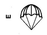
係合用要素の形状、サイズ、および構造/構成は限定されず、血液血管と適合し治療に適した程度に変化することができる。特定の実施形態では、係合用要素は、一般に、円錐形または四角錘形(図14Aに示される)、円筒形または管状形(図14C)、楕円(図14D)、または球形(図14D)、または傘(またはパラシュート)形(図14E)など、および上記で説明した形/形状のいずれかの組合せに成形可能である。一例が図14Bに示されている。係合用要素は、円筒形または管状形であるとき、両方の端において開いていてもよいし、閉鎖されてもよい。同じデバイス内に存在する個々の係合用要素は、たとえば、サイズ、構造、材料、および/または機能に関して互いと異なってよい。あるいは、同じデバイス内に存在する係合用要素のうちのいくつかまたはすべては、その中で1つまたは複数の共通する特徴、たとえば、サイズ、構造、材料、および機能を共有することができる。 The shape, size, and structure / configuration of the engaging element is not limited and can be varied to a degree compatible with the blood vessel and suitable for treatment. In certain embodiments, the engagement element is generally conical or pyramidal (shown in FIG. 14A), cylindrical or tubular (FIG. 14C), oval (FIG. 14D), or spherical (FIG. 14D), Or can be shaped into an umbrella (or parachute) shape or the like (FIG. 14E), and any combination of the shapes / shapes described above. An example is shown in FIG. 14B. The engagement element may be open or closed at both ends when it is cylindrical or tubular in shape. The individual engagement elements present in the same device may, for example, differ from one another in terms of size, structure, material and / or function. Alternatively, some or all of the engagement elements present in the same device may share one or more common features therein, eg, size, structure, material and function.
さらに、いくつかの実施形態では、デバイスの係合用要素のうちの2つ以上と関連する接続ワイヤが存在する。いくつかの実施形態では、接続ワイヤは、複数の係合用要素のうちの特定のものまたはいくつか(すべてではない)を接続してもよいし、これらと関連付けられてもよい。いくつかの他の実施形態では、接続ワイヤは、デバイス内に存在する係合用要素のすべてと関連付けられてもよいし、これらと接続してもよい。接続ワイヤと個々の係合用要素との間の関連付けまたは接続は、接続ワイヤのある位置で固定されてもよい。複数の係合用要素が、接続ワイヤと関連付けられる(または、これに接続される)とき、個々の係合用要素の接続ワイヤとの関連付け/接続のタイプ、たとえば、固定様式または非固定様式は、単一デバイス内で変化してもよい。したがって、いくつかの実施形態では、同じ接続ワイヤと関連付けられたまたはこれと接続された係合用要素のうちのいくつか(すべてではない)は、接続ワイヤのそれぞれの位置で固定されてよい。接続ワイヤは、可撓性すなわち柔軟(floppy)とすることができ、これによって、係合用要素同士の距離を縮めることが望ましいとき、係合用要素間のスペースを短縮することができる。これらの環境では、係合用要素間の最大距離も接続ワイヤによって制限されるように、接続ワイヤは、張力を受けている間、伸張抵抗性であってよい。 Furthermore, in some embodiments, there are connection wires associated with two or more of the engagement elements of the device. In some embodiments, the connecting wire may connect or be associated with certain or some (not all) of the plurality of engaging elements. In some other embodiments, the connection wire may be associated with or connected to all of the engagement elements present in the device. The association or connection between the connection wire and the individual engagement elements may be fixed at one position of the connection wire. When multiple engagement elements are associated with (or connected to) the connection wire, the type of association / connection of the individual engagement elements with the connection wire, for example the fixed or non-fixed manner, It may change within one device. Thus, in some embodiments, some (but not all) of the engagement elements associated with or connected to the same connection wire may be fixed at each position of the connection wire. The connecting wires may be flexible or floppy, which may reduce the space between the engagement elements when it is desired to reduce the distance between the engagement elements. In these circumstances, the connecting wire may be stretch resistant while under tension, such that the maximum distance between the engaging elements is also limited by the connecting wire.
接続ワイヤと係合用要素との間の関連付け(すなわち、接続)、特に、それらの間の固定(または接合)は、溶接、接着、またはクリッピングなどのさまざまな手段を介して行われてよい。管またはコネクタなどの追加要素は、係合用要素および接続ワイヤがそれに固定される場合、存在することができる。接続ワイヤと係合用要素との間の関連付け(すなわち、接続)は、特に、係合用要素が中心ワイヤに沿って動くことができる場合、コネクタを含むさまざまな手段(たとえばコネクタ)を介して行われることが可能である。たとえば、係合用要素は、短い内側要素コネクタ管および外側要素コネクタ管を含んでもよいし、これらに取り付けられてもよい。接続ワイヤは、2つの管の壁同士の間に取り付けられてよく、中心ワイヤは、内側要素コネクタ管を通って(その内部を)通過してよい。したがって、係合用要素は、特定の位置に固定されずに中心ワイヤに沿って動く(摺動する)ことができる。 The association (i.e. connection) between the connection wire and the engagement element, in particular the fixation (or bonding) between them, may be performed via various means such as welding, gluing or clipping. Additional elements such as tubes or connectors can be present if the engagement element and the connecting wire are fixed to it. The association (i.e. connection) between the connection wire and the engagement element takes place via various means (e.g. a connector) including a connector, in particular if the engagement element can move along the central wire It is possible. For example, the engagement elements may include or be attached to short inner element connector tubes and outer element connector tubes. A connecting wire may be attached between the walls of the two tubes, and a center wire may pass through (internal to) the inner element connector tube. Thus, the engagement element can move (slide) along the center wire without being fixed in a particular position.
いくつかの設計では、スペーシング・ワイヤも存在してよい。係合用要素は、スペーシング・ワイヤに固定可能である。スペーシング・ワイヤは接続ワイヤよりも剛性がやや高くてよく、したがって、曲がったり、たるんだりしない。したがって、スペーシング・ワイヤは、係合用要素間で固定されたスペースまたは距離を維持する。 In some designs, spacing wires may also be present. The engagement element is fixable to the spacing wire. Spacing wires may be somewhat stiffer than connecting wires and thus will not bend or sag. Thus, the spacing wires maintain a fixed space or distance between the engagement elements.
接続ワイヤおよび/またはスペーシング・ワイヤは、丸いもしくは平坦なワイヤ、ケーブルの形をとる、またはブレード構造を有することができる。接続ワイヤは、いくつかの実施形態では、可撓性であるが伸張抵抗性である。接続ワイヤのための金属材料のいくつかの非限定的な例は、ニッケル、チタン、ステンレス鋼、コバルト、クロム、およびニチノール(NiTi)、チタン合金、またはコバルトクロム合金などの前述のものの任意の合金を含んでよい。さらに、接続ワイヤであるという所望の性質を有する任意のポリマーまたはプラスチックが、その生産に使用可能である。ポリマーとしては、限定するものではないが、ポリイミド、PEEK(ポリエーテルエーテルケトン)、ナイロン、PTFE(ポリテトラフルオロエチレン)、PET(ポリエチレンテレフタレート)、ポリプロピレンなどがある。限定するものではないがPTFE被覆ステンレス鋼またはPTFE被覆NiTiを含むポリマー被覆金属も、接続ワイヤとして使用可能である。また、親水性コーティングも適用可能である。 The connecting wires and / or spacing wires can be in the form of round or flat wires, cables or have a blade structure. The connecting wire is flexible but stretch resistant in some embodiments. Some non-limiting examples of metallic materials for connecting wires are nickel, titanium, stainless steel, cobalt, chromium, and any of the aforementioned alloys such as nitinol (NiTi), titanium alloys, or cobalt chromium alloys May be included. Furthermore, any polymer or plastic having the desired properties of being a connecting wire can be used for its production. The polymer includes, but is not limited to, polyimide, PEEK (polyether ether ketone), nylon, PTFE (polytetrafluoroethylene), PET (polyethylene terephthalate), polypropylene and the like. Polymer coated metals including but not limited to PTFE coated stainless steel or PTFE coated NiTi can also be used as the connecting wire. Also hydrophilic coatings are applicable.
特定の実施形態では、複数の接続ワイヤが存在することができる。そのような実施形態のうちのいくつかでは、接続ワイヤは、デバイス内に存在する係合用要素のすべてと関連付けられてもよいし、これらと接続してもよい。あるいは、接続ワイヤは、係合用要素のペア、すなわち受け入れ用係合用要素および捕捉用係合用要素と関連付けられてもよいし、これらと接続してもよい。特定の実施形態では、単一デバイス内に存在する2つ、3つ、4つ、5つ、6つ、またはそれ以上の接続ワイヤが存在することができる。いくつかの他の実施形態では、デバイスは、7つ以上の接続ワイヤを有することができる。 In certain embodiments, multiple connection wires can be present. In some of such embodiments, the connecting wire may be associated with or connected to all of the engagement elements present in the device. Alternatively, the connecting wire may be associated with or connected to the pair of engagement elements, ie, the receiving engagement element and the capture engagement element. In certain embodiments, there may be two, three, four, five, six or more connection wires present in a single device. In some other embodiments, the device can have seven or more connection wires.
いくつかの実施形態では、デバイスは、最も近位に配置された係合用要素と関連付けられ、関連付けられた係合用要素の位置を制御することが可能であることができる近位端制御要素を備えてよい。特定の実施形態では、近位端制御要素は、管区画またはワイヤの形をとることができる。近位端制御要素は、係合用要素の最近位端の境界を設定することができる。特定の実施形態では、近位端制御要素は、近位端制御要素の動きを制御可能なハンドルに動作可能に連結されてよい。 In some embodiments, the device comprises a proximal end control element that can be associated with the most proximally disposed engagement element and capable of controlling the position of the associated engagement element You may In certain embodiments, the proximal end control element can be in the form of a tube segment or a wire. The proximal end control element can set the boundary of the most proximal end of the engagement element. In certain embodiments, the proximal end control element may be operably coupled to a handle that can control movement of the proximal end control element.
デバイスが複数の係合用要素を備えるいくつかの実施形態では、デバイスは、デバイスの近位係合用要素と関連付けられた(または、これに接続した)管区画をさらに備えてよい。いくつかの実施形態では、近位係合用要素以外の他の係合用要素が、接続ワイヤまたはスペーシング・ワイヤのどちらか(その両方は、近位係合用要素と他の係合用要素との間の所望のスペースを維持する助けとなり得る)を介して管と関連付け(または、これに接続)可能である。いくつかの実施形態では、近位係合用要素は、その近位端コネクタを介して管区画の遠位端のまわりに固定可能である。したがって、そのような実施形態では、接続ワイヤまたはスペーシング・ワイヤに固定された近位係合用要素および他の要素の動きが、管区画によって制御される。 In some embodiments where the device comprises a plurality of engagement elements, the device may further comprise a tube section associated with (or connected to) the proximal engagement element of the device. In some embodiments, other engagement elements other than the proximal engagement element are either connection wires or spacing wires (both are between the proximal engagement element and the other engagement element). It can be associated with (or connected to) the tube via (which can help maintain the desired space). In some embodiments, the proximal engagement element is fixable around the distal end of the tube segment via its proximal end connector. Thus, in such embodiments, the movement of the proximal engagement element and other elements fixed to the connection or spacing wire is controlled by the tube section.
代替実施形態では、デバイスは、複数の係合用要素を備えてよく、デバイスの1つまたは複数の係合用要素と関連付けられた(または、これに接続した)制御ワイヤも備えてよい。いくつかの実施形態では、制御ワイヤは、デバイスの近位係合用要素と関連付けられてよい。制御ワイヤと近位係合用要素との間の関連付け(または接続)は、係合用要素が制御ワイヤのある位置に固定される固定または接合を含んでよい。したがって、近位係合用要素の動きは、制御ワイヤを押すまたは引っ張ることによって制御される。 In alternative embodiments, the device may comprise a plurality of engagement elements, and may also comprise control wires associated with (or connected to) one or more engagement elements of the device. In some embodiments, a control wire may be associated with the proximal engagement element of the device. The association (or connection) between the control wire and the proximal engagement element may comprise a fixation or joint in which the engagement element is fixed at a position of the control wire. Thus, the movement of the proximal engagement element is controlled by pushing or pulling on the control wire.
複数の係合用要素が制御ワイヤと関連付けられている特定の実施形態では、関連付けられた係合用要素の各々は、制御ワイヤ上のそのそれぞれの位置に固定可能である。複数の係合用要素(受け入れ用要素)が制御ワイヤと関連付けられているいくつかの実施形態では、関連付けられた係合用要素のいくつか(すべてではない)は、係合用要素コネクタ管を介して制御ワイヤまたはスペーシング・ワイヤ上のそれぞれの位置に固定される。これらの係合用要素は、受け入れ用要素と捕捉要素との間のスペースを変更するために中心ワイヤに沿って動くことができる。 In certain embodiments in which a plurality of engagement elements are associated with the control wire, each of the associated engagement elements is fixable at its respective position on the control wire. In some embodiments where multiple engaging elements (receiving elements) are associated with the control wire, some, but not all, of the associated engaging elements are controlled via the engaging element connector tube Fixed in their respective position on the wire or spacing wire. These engagement elements can move along the center wire to change the space between the receiving element and the capture element.
いくつかの実施形態では、制御ワイヤは、オペレータ(たとえば、開業医)がハンドルを介して制御ワイヤを制御(または起動)する、たとえば制御ワイヤを押すまたは引っ張ることができるように、デバイスの近位端でハンドルに動作可能に連結または接続される。制御ワイヤの動きを制御するこの制御動作は、制御ワイヤおよびスペーシング・ワイヤと関連付けられた係合用要素の運動の制御になる。 In some embodiments, the control wire controls (or actuates) the control wire through the handle, eg, the proximal end of the device, so that an operator (eg, a practitioner) can control (or activate) the control wire. Are operatively connected or connected to the handle at This control action, which controls the movement of the control wire, becomes the control of the movement of the control wire and the engagement element associated with the spacing wire.
制御ワイヤは、ワイヤ、ケーブル、ブレード、または管の形をとることができる。接続ワイヤのための金属材料のいくつかの非限定的な例は、ニッケル、チタン、ステンレス鋼、コバルト、クロム、およびニチノール(NiTi)、チタン合金、またはコバルトクロム合金などの前述のものの任意の合金を含んでよい。さらに、制御ワイヤであるという所望の性質を有する任意のポリマーまたはプラスチックが、その生産に使用可能である。ポリマーとしては、限定するものではないが、ポリイミド、PEEK(ポリエーテルエーテルケトン)、ナイロン、PTFE(ポリテトラフルオロエチレン)、PET(ポリエチレンテレフタレート)、ポリプロピレンなどがある。限定するものではないがPTFE被覆ステンレス鋼またはPTFE被覆NiTiを含むポリマー被覆金属も、制御ワイヤとして使用可能である。また、親水性コーティングも適用可能である。 The control wire can be in the form of a wire, a cable, a blade or a tube. Some non-limiting examples of metallic materials for connecting wires are nickel, titanium, stainless steel, cobalt, chromium, and any of the aforementioned alloys such as nitinol (NiTi), titanium alloys, or cobalt chromium alloys May be included. In addition, any polymer or plastic having the desired properties of being a control wire can be used for its production. The polymer includes, but is not limited to, polyimide, PEEK (polyether ether ketone), nylon, PTFE (polytetrafluoroethylene), PET (polyethylene terephthalate), polypropylene and the like. Polymer coated metals including but not limited to PTFE coated stainless steel or PTFE coated NiTi can also be used as control wires. Also hydrophilic coatings are applicable.
いくつかの実施形態では、個々の係合用要素は、制御ワイヤ、接続ワイヤ、スペーシング・ワイヤ、および中心ワイヤからなる群から選択されるワイヤのうちの1つまたは複数と関連付け(または、これに接続)可能である。さらに、個々の係合用要素がワイヤのうちの少なくとも2つと関連付けられる(または、これに接続される)とき、係合用要素は、他の関連付けられた/接続されたワイヤに沿って移動可能でありながら、関連付けられた/接続されたワイヤのうちの少なくとも1つに対してある位置に固定可能である。したがって、たとえば、係合用要素は、制御ワイヤまたはスペーシング・ワイヤと関連付けられた、すなわち、制御ワイヤまたはスペーシング・ワイヤに固定される場合、依然として他のワイヤ上で移動可能であることができる。 In some embodiments, individual engagement elements are associated with (or to) one or more of the wires selected from the group consisting of control wires, connection wires, spacing wires, and center wires. Connection is possible. Furthermore, when an individual engagement element is associated with (or connected to) at least two of the wires, the engagement element is movable along the other associated / connected wires While, it can be fixed at a certain position relative to at least one of the associated / connected wires. Thus, for example, the engagement element may still be movable on the other wire if it is associated with the control wire or spacing wire, ie fixed to the control wire or spacing wire.
個々の係合用要素が、1つまたは複数のワイヤ(たとえば、制御ワイヤ、接続ワイヤ、スペーシング・ワイヤ、および中心ワイヤ)のうちの1つまたは複数を制御することによって、そのようなワイヤと関連付けられる(または、これに接続される)とき、個々の係合用要素の位置が制御可能である。さらに、係合用要素間のスペースまたは距離も、それぞれ関連付けられた/接続されたワイヤの制御を介して調整可能である。したがって、体腔から閉塞を除去または治療するようにデバイスを用いて閉塞を係合し、これを含もうとしている間、オペレータは、単一の係合用要素または2つ以上の係合用要素を動作ユニット/ペアとして起動することができる。この複雑で微細な動作モードは、体腔を損傷するリスクを最小にしながら、治療の効率を著しく向上させる。 Individual engagement elements associate with such wires by controlling one or more of one or more wires (eg, control wires, connection wires, spacing wires, and center wires) When being (or connected to) the position of the individual engagement elements is controllable. Furthermore, the spacing or distance between the engagement elements can also be adjusted via control of the associated / connected wires, respectively. Thus, while engaging and involving the occlusion with the device to remove or treat the occlusion from the body cavity, the operator operates the single engagement element or two or more engagement elements into the operating unit Can be launched as a / pair. This complex and fine mode of operation significantly improves the efficiency of the treatment while minimizing the risk of damaging the body cavity.
制御ワイヤ(または管区画)は、中心ワイヤから分離され、これに取り付けられず、したがって、独立して動いてよい。いくつかの実施形態では、制御ワイヤまたは管区画と中心ワイヤを制御するように構成された別個の近位ハンドルが存在する。これらのハンドルは、コントローラとして作用する。これらのハンドルを動作させ、中心ワイヤと制御ワイヤまたは管区画を制御することによって、デバイスの個々の係合用要素は、所望のロケーションに位置決め可能であり、また、体腔からの閉塞の把持/捕捉/除去を最大にするように、係合用要素のうちの2つ以上の間のスペース/距離が調整可能である。あるいは、または制御ワイヤもしくは管区画、および中心ワイヤと組み合わせて、接続ワイヤおよび/または特定の実施形態ではスペーシング・ワイヤは、2つ以上の係合用要素の間のスペースまたは距離を制御することも可能である。たとえば、接続ワイヤは、中心ワイヤおよび制御ワイヤとは別個であり、独立して動いてよい。したがって、接続ワイヤは、1つまたは複数の係合用要素間のスペース/距離を短縮することを可能にしてよい。中心ワイヤが近位に引っ張られるまたは制御ワイヤもしくは管区画が遠位に押されるとき、受け入れ用要素と捕捉用要素との間のスペースは、血塊をしっかり掴むまたは保持するように短縮される。制御ワイヤまたは管区画を近位に引っ張り、中心ワイヤを保持しながら、接続ワイヤに張力がかけられるまで、捕捉用要素と受け入れ用要素との間の距離が増加する。これによって、要素が互いに重なることなく、係合区画の構成要素がマイクロカテーテルへと引っ込められることが可能になる。 The control wire (or tube section) is separate from the central wire and not attached to it, and may therefore move independently. In some embodiments, there is a separate proximal handle configured to control the control wire or tube segment and the central wire. These handles act as controllers. By operating these handles and controlling the center and control wires or tube segments, the individual engagement elements of the device can be positioned at the desired location and also the grasp / capture of the occlusion from the body cavity The space / distance between two or more of the engagement elements is adjustable to maximize removal. Alternatively, or in combination with the control wire or tube segment, and the center wire, the connection wire and / or the spacing wire in certain embodiments may control the space or distance between two or more engagement elements. It is possible. For example, the connection wires may be separate and move independently of the center and control wires. Thus, the connection wires may allow to reduce the space / distance between the one or more engagement elements. When the central wire is pulled proximally or the control wire or tube segment is pushed distally, the space between the receiving element and the capturing element is shortened to grip or hold the clot. While pulling the control wire or tube section proximally and holding the central wire, the distance between the capture element and the receiving element increases until the connecting wire is tensioned. This allows the components of the engagement section to be retracted into the microcatheter without the elements overlapping each other.
いくつかの実施形態では、デバイスは、閉塞を捕捉/しっかり掴んで、それを体腔から除去するように4つ以上の係合用要素が一緒に動作する、2つ以上の係合ユニット/ペアを備えてよい。特定の実施形態では、係合ユニット/ペアは、2つの係合用要素、すなわち、1つは受け入れ用要素として機能し、もう1つは捕捉用要素として機能する係合用要素を備えてよい。いくつかの実施形態では、係合ユニット/ペア内で、捕捉用要素は遠位に配置可能であるが、受け入れ用要素は近位に配置可能である。捕捉用要素は、閉塞と係合(たとえば、捕捉、または把持)可能であるように形成されてよい。捕捉用要素は、要素本体のその近位端を用いて、またはそのワイヤ/ストラット構造によって、閉塞に接触するストラットの任意の部品に沿って閉塞と直接係合することができる。あるいは、閉塞は、体腔と捕捉用要素との間で摩擦係合することができる。依然としてあるいは、閉塞は、捕捉用要素と受け入れ用要素との間で捕捉、しっかり掴む、または保持可能である。閉塞の捕捉、係合、しっかり掴むこと、または保持のためのこれらの機構のすべては、閉塞と係合して除去するように同時に働いてよく、たとえば、閉塞のある部分は、捕捉用要素および体腔と(捕捉用要素と体腔の間で)摩擦係合してよく、閉塞の何らかの他の部分は、受け入れ用要素と係合してよい。複数の係合用要素および体腔を使用する閉塞の捕捉または係合のさまざまなモードが存在することができ、そのような変形形態のいずれも、本明細書で開示される方法およびデバイスの範囲内に包含される。 In some embodiments, the device comprises two or more engagement units / pairs in which four or more engagement elements operate together to capture / grip an occlusion and remove it from the body cavity You may In a particular embodiment, the engagement unit / pair may comprise two engagement elements, one acting as a receiving element and the other an engaging element acting as a capture element. In some embodiments, within the engagement unit / pair, the capture element can be disposed distally while the reception element can be disposed proximally. The capture element may be configured to be capable of engaging (eg, capturing or gripping) an occlusion. The capture element can be in direct engagement with the occlusion along any part of the strut that contacts the occlusion using its proximal end of the element body or by its wire / strut structure. Alternatively, the occlusion can be frictionally engaged between the body cavity and the capture element. Still alternatively, the occlusion can be captured, gripped or held between the capture and receiving elements. All of these mechanisms for catching, engaging, firmly gripping or holding an occlusion may act simultaneously to engage and remove the occlusion, eg, the part with the occlusion may be a capture element and There may be frictional engagement with the body cavity (between the capture element and the body cavity) and some other portion of the occlusion may be engaged with the receiving element. There may be multiple modes of engagement capture and occlusion using occlusion elements and body lumens, any such variation being within the scope of the methods and devices disclosed herein. Is included.
特定の実施形態では、遠位係合用要素は、単独でまたは別の近位に配置された係合用要素もしくは受け入れ用要素および/もしくは体腔と組み合わせて閉塞を捕捉できるように、網を形成する複数のワイヤまたはストラットを備えてよい。より近位の係合用要素または受け入れ用要素は、そのワイヤまたはストラットを介して所望されるまたは必要な場合は閉塞と直接係合することを可能とすることもできるが、より遠位の係合用要素または捕捉用要素によって閉塞の係合を保証または強化するように機能することもできる。たとえば、閉塞が比較的大きいまたは体腔に沿ってある距離延びる特定の場合では、複数の係合用要素または複数の捕捉用要素および受け入れ用要素(および、多くの場合は、体腔との摩擦係合と共に)は、血塊のより完全な係合を保証するために複数のロケーションで閉塞と係合するように作用することができる。たとえば、図2Bおよび図9A〜図9Cに示される非限定的で例示的な実施形態を参照されたい。あるいは、個々の係合(または動作)ユニット/ペアは、別個の閉塞を除去するように別個に動作する。たとえば、図9D〜図9Fに示される非限定的で例示的な実施形態を参照されたい。また、あるいはまたは前述のモードのうちの少なくとも1つと組み合わせて、受け入れ用要素またはより近位の係合用要素は、2つの隣接要素間で血塊を保持またはしっかり掴む捕捉用要素またはより遠位の係合用要素に接近することができ、これは、閉塞のより完全またはより強力な捕捉をもたらし得る。特定の実施形態では、近位係合用要素または受け入れ用要素は、より遠位の係合用要素または捕捉用要素の近位部分に適合できるような形状であってよい。言い換えれば、遠位係合用要素または捕捉用要素の近位部分は、より近位の係合用要素または受け入れ用要素の遠位部分に嵌合してよい。したがって、2つの要素間の閉塞の閉じ込めは、治療手順中に、および管腔からのデバイスの除去中も、さらに確保可能である。 In certain embodiments, the distal engagement elements form a mesh so that occlusions can be captured, either alone or in combination with another proximally disposed engagement element or receiving element and / or a body cavity. Wires or struts may be provided. The more proximal engaging or receiving element can also allow direct engagement with the occlusion if desired or necessary via its wires or struts, but for more distal engagement The element or capture element can also function to assure or enhance engagement of the occlusion. For example, in certain cases where the occlusion is relatively large or extends a distance along the body cavity, multiple engagement elements or multiple capture and reception elements (and often with frictional engagement with the body cavity) Can act to engage the occlusion at multiple locations to ensure more complete engagement of the clot. See, for example, the non-limiting and exemplary embodiments shown in FIGS. 2B and 9A-9C. Alternatively, the individual engagement (or operation) units / pairs operate separately to remove a separate occlusion. See, for example, the non-limiting exemplary embodiments shown in FIGS. 9D-9F. Also or alternatively or in combination with at least one of the aforementioned modes, the receiving element or more proximal engagement element is a capture element or more distal engagement which holds or firmly grips a clot between two adjacent elements The access element can be approached, which can result in more complete or stronger capture of the occlusion. In certain embodiments, the proximal engagement or reception element may be shaped to be compatible with the more distal engagement or capture element proximal portion. In other words, the proximal portion of the distal engagement or capture element may mate with the distal portion of the more proximal engagement or reception element. Thus, confinement of the occlusion between the two elements can be further ensured during the treatment procedure and also during removal of the device from the lumen.
いくつかの実施形態では、デバイスは、3つ以上の動作ユニット/ペアを備えることができる。したがって、特定の実施形態では、デバイスは、3つ、4つ、5つ、6つ、またはそれ以上の動作ユニット/ペアを備えてよい。特定の実施形態では、遠位係合用要素またはデバイスの遠位端は、体腔内の閉塞を完全には越えないことがある。むしろ、デバイスは、たとえば図9A〜図9Fに示されるように、閉塞の近位端の一部のみへと進み、閉塞の一部のみと係合することがある。たとえば、封鎖(閉塞)がどれくらい長く管腔内で延びているか、すなわち、閉塞の遠位端はどこかを可視化することが困難または不可能な場合がある。これらの状況では、閉塞の一部のみによって、またはその中でデバイスを前進させ、また、閉塞のその部分のみと係合する方が安全であると判断されることがある。しかしながら、いくつかの他の場合、デバイスが閉塞の遠位端を越えて前進されることが安全な操作であり得ると判断されるとき、これがなされることがある。 In some embodiments, the device can comprise more than two operating units / pairs. Thus, in particular embodiments, the device may comprise three, four, five, six or more operating units / pairs. In certain embodiments, the distal end of the distal engagement element or device may not completely exceed the occlusion in the body cavity. Rather, the device may advance to only a portion of the proximal end of the occlusion and engage only a portion of the occlusion, as shown, for example, in FIGS. 9A-9F. For example, it may be difficult or impossible to visualize how long the blockade (occlusion) extends in the lumen, ie where the distal end of the occlusion is. In these situations, it may be determined that it is safer to advance the device by, or within, only a portion of the occlusion and to engage only that portion of the occlusion. However, in some other cases this may be done when it is determined that advancing the device beyond the distal end of the occlusion may be a safe operation.
いくつかの実施形態では、個々の係合用要素の位置または動作ユニット/ペアの位置は、中心ワイヤ、制御管/ワイヤ区画、接続ワイヤ、スペーシング・ワイヤ、および制御ワイヤからなる群から選択された少なくとも1つのものの動きを介して調整可能である。一般に、デバイス内のすべての係合用要素は、中心ワイヤと関連付けられ(または、これに接続され)てよい。いくつかの実施形態では、係合用要素のいくつかのみ(すべてではない)が、中心ワイヤ上のそれぞれの位置に固定されてよいが、いくつかの他の係合用要素は、依然として、制御ワイヤに沿って移動可能であってよい。特定の実施形態では、デバイスの(異なる動作ユニット/ペアからの)すべての捕捉用要素は、中心ワイヤ内のそれぞれの位置に固定されてよいが、すべての受け入れ用要素は中心ワイヤに沿って移動可能であってよい。 In some embodiments, the position of the individual engagement elements or the position of the operating unit / pair is selected from the group consisting of center wire, control tube / wire section, connection wire, spacing wire, and control wire It is adjustable via the movement of at least one thing. In general, all engaging elements in the device may be associated with (or connected to) the center wire. In some embodiments, only some (but not all) of the engagement elements may be fixed in their respective positions on the center wire, but some other engagement elements are still on the control wire It may be movable along. In certain embodiments, all capture elements (from different operating units / pairs) of the device may be fixed at their respective positions in the center wire, but all reception elements move along the center wire It may be possible.
説明のために、本発明によるデバイスのいくつかの非限定的で例示的な例が、以下の図で提供されている。本明細書では、説明のためにほんのわずかの例示的な適用例が説明されているが、当業者には明らかであろう多数の異なる修正および交代も、本発明の範囲に影響することなく行われることが可能である。したがって、本出願に開示されている例だけでなく、そのような明らかな修正および交代もまた、本発明の範囲に含まれるべきである。 For the purpose of illustration, several non-limiting and illustrative examples of devices according to the present invention are provided in the following figures. Although only a few exemplary applications are described herein for the purpose of illustration, numerous different modifications and alterations that would be apparent to one of ordinary skill in the art are also within the scope of the present invention. It is possible to be Thus, not only the examples disclosed in the present application, but also such obvious modifications and alterations should be included within the scope of the present invention.
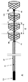
図1は、デバイスが複数の係合用要素を備えてよいデバイスの一実施形態を示す。いくつかの実施形態では、デバイスは、3つ以上の係合用要素を備えてよい。いくつかの実施形態では、デバイスは、中心ワイヤ(10)と、管区画(27)と、3つ以上の係合用要素(65、67、90)と、接続ワイヤ(190)とを備えてよい。この図は、遠位係合用要素(90)と近位係合用要素(65)と2つの中央係合用要素(67)とを含む4つの係合用要素を示す。この例では、最も遠位の係合用要素(90)は捕捉用要素として機能し、この近位にあるすべての係合用要素は、捕捉用要素および/または受け入れ用要素として機能してよい。個々の係合用要素は、延長されたとき、長さに関して3〜25mmで変化してよい。図1Aは、その開放状態にあり、すなわち、各隣接する係合用要素間のスペースは完全に開放されており、スペースの長さは「d」とマークされる。図1Bは、その閉鎖状態にあり、すなわち、閉塞または血塊を保持、しっかり掴む、または把持するために、各係合用要素間のスペースが(「d」から「d1」に)短縮される。 FIG. 1 illustrates one embodiment of a device where the device may comprise a plurality of engagement elements. In some embodiments, the device may comprise more than two engagement elements. In some embodiments, the device may comprise a central wire (10), a tube section (27), three or more engaging elements (65, 67, 90) and a connecting wire (190) . This figure shows four engagement elements including a distal engagement element (90), a proximal engagement element (65) and two central engagement elements (67). In this example, the most distal engagement element (90) functions as a capture element, and all the engagement elements in the proximity may function as a capture element and / or a reception element. The individual engagement elements may vary in length by 3 to 25 mm when extended. FIG. 1A is in its open state, ie, the space between each adjacent engagement element is completely open, and the length of the space is marked “d”. FIG. 1B shows that in the closed state, the space between each engagement element is shortened (from “d” to “d1”) in order to hold, firmly grip or grip the occlusion or clot.
いくつかの実施形態では、すべての複数の係合用要素(65、67、および90)は、中心ワイヤ(10)と関連付けられる(または、これに接続される)。これらのうち、遠位係合用要素(90)の近位端は中心ワイヤ(10)の遠位端(または先端)に固定可能であるが、他の3つの係合用要素(65および67)は、中心ワイヤ上で自由に摺動することができる。また、すべての複数の係合用要素は、接続ワイヤ(190)と関連付け可能である。いくつかの実施形態では、可撓性接続ワイヤ(190)は、それらの間のあらかじめ設定されたまたは等しいスペースで、すべての係合用要素の近位端を連結することができる。そのような実施形態では、係合用要素は、接続ワイヤ上のそれぞれの位置に固定され、特定の操作を用いて、その距離を維持する。さらに、いくつかの実施形態では、近位係合用要素(65)の近位端は、管区画(27)の遠位端に固定可能である。中心ワイヤは、管区画の内部で自由に摺動することができる。特定の実施形態では、デバイスは、中心ワイヤを制御する(たとえば、これを押すまたは引っ張る)ことが可能であるように、デバイスの近位端にハンドル(110)をさらに備えてもよいし、これに動作可能に連結されてもよい。 In some embodiments, all the plurality of engagement elements (65, 67 and 90) are associated with (or connected to) the center wire (10). Of these, the proximal end of the distal engagement element (90) can be fixed to the distal end (or tip) of the central wire (10) while the other three engagement elements (65 and 67) are , Can slide freely on the central wire. Also, all the plurality of engagement elements can be associated with the connecting wire (190). In some embodiments, the flexible connection wire (190) can connect the proximal ends of all the engagement elements with a preset or equal space between them. In such embodiments, the engagement elements are fixed in their respective positions on the connecting wire and maintain their distance using a specific operation. Furthermore, in some embodiments, the proximal end of the proximal engagement element (65) is fixable to the distal end of the tube section (27). The central wire can slide freely inside the tube section. In certain embodiments, the device may further comprise a handle (110) at the proximal end of the device to be able to control (eg, push or pull) the center wire May be operably coupled to
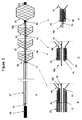
図2は、体腔内の閉塞/血塊を除去または治療するために、図1に示される係合用要素などの複数の係合用要素を備えるデバイスが使用される、方法の別の実施形態を示す。 FIG. 2 shows another embodiment of the method in which a device comprising multiple engaging elements, such as the engaging elements shown in FIG. 1, is used to remove or treat an occlusion / clot in a body cavity.
いくつかの実施形態では、デバイスは、マイクロカテーテル(30)を通って血液血管へと導入可能である。体腔内の閉塞部位に到達すると、およびマイクロカテーテルを通してデバイスを押したとき、遠位係合用要素(90)は、最初に、中心ワイヤを用いて前方に押されてよい。中心ワイヤ上で押圧力を継続することによって、張力がかけられた状態で接続ワイヤが維持され、接続ワイヤに関連付けられた各係合用要素がマイクロカテーテル管腔に沿って前方に引っ張られる。さらに、マイクロカテーテルを後退させながら前方への押圧力を継続することによって、オペレータが、デバイスを露出させ、係合用要素間の設定された距離を維持することが可能になる。接続ワイヤは可撓性であり得るが、一般に伸張可能ではないので、それによって、係合用要素は、たるんでいるときには互いに接近することができるが、係合用要素が張力をかけられているときに、あらかじめ設定された距離よりも長く分離されることを防止する。係合用要素は、マイクロカテーテルから露出されると、それらの間のあらかじめ設定された距離で位置決めされる。 In some embodiments, the device can be introduced into the blood vessel through the microcatheter (30). Once the occlusion site in the body cavity is reached and the device is pushed through the microcatheter, the distal engagement element (90) may be initially pushed forward with the central wire. Continued pressure on the center wire maintains the connection wire in tension and pulls each engagement element associated with the connection wire forward along the microcatheter lumen. In addition, continuing the forward pressure while retracting the microcatheter allows the operator to expose the device and maintain the set distance between the engagement elements. The connecting wires can be flexible but are not generally extensible, so that the engaging elements can come close to one another when slack, but when the engaging elements are under tension , To prevent separation longer than a preset distance. The engaging elements, when exposed from the microcatheter, are positioned at a preset distance therebetween.
露出されるとき、中心ワイヤ(10)は、中心ワイヤの遠位端に固定された遠位係合用要素(90)が安定化可能であるように、安定して保持され得る。マイクロカテーテルの内側管腔と係合用要素(65および67)の表面との間の摩擦は、自由に摺動する係合用要素を後方に動かすことができる。しかしながら、接続ワイヤは伸張可能ではないので、各要素間のあらかじめ設定されたスペースを保持する。露出後、係合用要素は、自己展開してよい。オペレータは、係合用要素間のスペースを調整することができる。血塊と係合するまたはこれを保持するために、オペレータは、(i)管区画(27)を安定して保持しながら、中心ワイヤを後方に(すなわち、近位に)引っ張ることによって、(ii)中心ワイヤを安定して保持しながら、管区画を前方に(すなわち、遠位に)押すことによって、または(iii)中心ワイヤを後方に引っ張って、管区画を前方に押すことによって、係合用要素間のスペースを短縮させてよい。この係合用要素の位置およびそれらの間のスペースの調整によって、血塊の少なくとも一部が圧縮する/しっかり掴むことが可能であるまたはスペース・ギャップ内に捕捉可能である。たとえば、図2B、図2Cを参照されたい。あるいは、または組み合わせて、閉塞は、体腔および1つまたは複数の係合用要素との摩擦係合を介して不動にすることができる。閉塞は、係合用要素のワイヤまたはストラットとも直接係合することができる。また、閉塞は、1つまたは複数の係合用要素と体腔との間で不動にされ、捕捉可能である。また、たとえば、図2B、図2Cを参照されたい。いくつかの実施形態では、閉塞の係合(捕捉)および閉じ込めは、複数のモードを伴ってよい。したがって、たとえば、閉塞の少なくとも一部は、1つまたは複数の係合用要素との直接係合によって捕捉されてよく、閉塞の少なくともいくつかの他の部分も、2つ以上の係合用要素のスペースの間に捕捉されてよい。また、あるいはまたは組み合わせて、閉塞の何らかの部分は、体腔および係合用要素によって摩擦捕捉され、不動にされることが可能である。 When exposed, the central wire (10) can be held stably such that the distal engagement element (90) fixed at the distal end of the central wire can be stabilized. Friction between the inner lumen of the microcatheter and the surface of the engagement elements (65 and 67) can move the freely sliding engagement elements back. However, since the connecting wires are not stretchable, they maintain a preset space between each element. After exposure, the engagement element may self-deploy. The operator can adjust the space between the engagement elements. In order to engage or hold the clot, the operator (i) pulls the central wire backwards (ie proximally) while holding the tube section (27) steady (ii) ) For engagement by pushing the tube section forward (ie, distally) while holding the central wire in a stable manner, or (iii) pulling the central wire backwards to push the tube section forward The space between elements may be shortened. By adjusting the position of the engagement elements and the space between them, at least a part of the clot can be compressed / held firmly or captured in the space gap. See, for example, FIGS. 2B and 2C. Alternatively, or in combination, the occlusion may be immobilized via frictional engagement with the body cavity and one or more engagement elements. The occlusion can also directly engage the wire or struts of the engagement element. Also, the occlusion may be immobilized and captured between the one or more engagement elements and the body cavity. See also, for example, FIGS. 2B and 2C. In some embodiments, occlusion engagement (capture) and confinement may involve multiple modes. Thus, for example, at least a portion of the occlusion may be captured by direct engagement with one or more engagement elements, and at least some other portions of the occlusion may also be spaces of two or more engagement elements May be captured between Also or alternatively, any part of the occlusion may be frictionally trapped and immobilized by the body cavity and the engagement element.
いくつかの実施形態では、治療手順中、管区画を保持しながら、中心ワイヤを近位に引っ張ることが可能である。次いで、遠位係合用要素が後方に動き、隣接する係合用要素を用いて血塊をしっかり掴むまたは保持してよい。次いで、近位係合用要素および/またはその隣接する係合用要素が、圧縮された血塊によって後方(すなわち、近位に)押され、次に、これによって、閉塞が圧縮され、しっかり掴まれる。オペレータは、閉塞がデバイスによって安全にしっかり掴まれる/把持されるまで、係合用要素間の距離を短縮することができる。閉塞を安全にしっかり掴む/把持するモードとしては、(1)閉塞が、係合用要素間でしっかり掴まれ得るまたは保持され得る、(2)閉塞は、1つまたは複数の係合用要素のワイヤまたはストラットと直接係合され得る、(3)閉塞は、体腔と係合用要素のうちの1つまたは複数との間で摩擦して含み得る、および(4)閉塞は、体腔と係合用要素間のスペースとの間で摩擦して含み得る、のうちの1つまたは複数があり得る。 In some embodiments, it is possible to pull the central wire proximally while holding the tube segment during the treatment procedure. The distal engagement element may then be moved backwards to securely grasp or hold the clot using the adjacent engagement elements. The proximal engagement element and / or its adjacent engagement element is then pushed rearward (ie, proximally) by the compressed clot, which in turn compresses the occlusion and grips it firmly. The operator can reduce the distance between the engagement elements until the occlusion is securely gripped / held by the device. As a mode of securely grasping / grasping the occlusion, (1) the occlusion may be firmly grasped or held between the engagement elements (2) the occlusion may be a wire or wires of one or more engagement elements The occlusion may be directly engaged with the struts, (3) the occlusion may include friction between the body cavity and one or more of the engagement elements, and (4) the occlusion may be between the body cavity and the engagement elements There may be one or more of which may include friction with the space.
閉塞が、デバイスによって安全に把持されるまたはしっかり掴まれると思われると、次いで、デバイスが体腔から引っ張り出され得る。いくつかの実施形態、たとえば図1Bおよび図2Cに示される実施形態では、接続ワイヤは、細く可撓性であってよく、したがって、係合用要素間の距離が短縮されるとき、屈曲する、カールする、またはお辞儀をすることができる。 The device may then be pulled out of the body cavity if the occlusion is deemed to be safely gripped or firmly gripped by the device. In some embodiments, such as the embodiments shown in FIGS. 1B and 2C, the connecting wires may be thin and flexible, and thus curl when the distance between the engagement elements is reduced. You can or bow.
図3は、デバイスが複数の係合用要素を備えてよいデバイスの別の実施形態を示す。いくつかの実施形態では、デバイスが、検索手順中にマイクロカテーテル(30)へと引っ込められることが必要なとき、管区画(27)は、後方に引っ張られることが可能である。管区画に固定された近位係合用要素(65)は、マイクロカテーテル(30)へと引っ張られることができる。接続ワイヤ(190)が張力をかけられた状態で維持されるとき、接続ワイヤ(190)は、接続ワイヤに接続される係合用要素をマイクロカテーテルへと1つずつ引っ張り込む。この回収機構によって、接続ワイヤが、係合用要素間のあらかじめ設定された距離まで延び、マイクロカテーテルへと引っ張り込むことができるように、複数の係合用要素が互いの上に積み重なることを防止することが可能になる。積み重なった係合用要素は、あまりにも大きい直径を持つのでマイクロカテーテルに嵌合しないことがあり、また、積み重なった位置に引っ張り込まれたときに損傷されることもある。 FIG. 3 shows another embodiment of the device wherein the device may comprise a plurality of engagement elements. In some embodiments, when the device needs to be retracted into the microcatheter (30) during a search procedure, the tube section (27) can be pulled backwards. The proximal engagement element (65) fixed to the tube section can be pulled into the microcatheter (30). When the connecting wire (190) is maintained in tension, the connecting wire (190) pulls the engagement elements connected to the connecting wire one by one into the microcatheter. The retrieval mechanism prevents multiple engagement elements from being stacked on top of one another so that the connecting wires can be extended to a preset distance between the engagement elements and pulled into the microcatheter Becomes possible. The stacked engagement elements may not fit into the microcatheter because they have too large a diameter and may also be damaged when pulled into the stacked position.
図4は、デバイスが複数の係合用要素を備えてよいデバイスのさらに別の実施形態を示す。いくつかの実施形態では、デバイスは、遠位フィルタとしても機能し得る遠位係合用要素(90)をさらに備えてよい。特定の実施形態では、遠位係合用要素の遠位端(または先端)は、遠位コネクタ(150)によって閉鎖可能である。いくつかの実施形態では、遠位係合用要素(90)の外形は、他の係合用要素の外形よりもサイズ(長さおよび直径)が大きくてよく、他の係合用要素よりも剛性でない。これによって、血管壁に対する遠位係合用要素の半径方向の力を最小にすることが可能になる。この遠位係合用要素、特に遠位フィルタ形では、血塊細片が下流に流れることを防止することができる。治療手順中に血塊(または閉塞)が断片化して細片を生成する場合、この細片は、この遠位フィルタ要素(90)によって捕捉される(収集されるまたは含まれる)ことが可能である。遠位係合用(フィルタ)要素の外形は大きく、好ましくは、回収パス内で血管の直径よりもやや大きいので、細片は、係合用要素と血管の壁との間で回避することが可能でなくてもよい。この実施形態では、遠位係合用要素は、より近位の隣接する係合用要素を用いて血塊をしっかり掴むまたは保持するように機能することもできる。 FIG. 4 shows yet another embodiment of the device where the device may comprise a plurality of engagement elements. In some embodiments, the device may further comprise a distal engagement element (90) that may also function as a distal filter. In certain embodiments, the distal end (or tip) of the distal engagement element is closable by the distal connector (150). In some embodiments, the outer profile of the distal engagement element (90) may be larger in size (length and diameter) than the outer profiles of the other engagement elements and less rigid than the other engagement elements. This makes it possible to minimize the radial force of the distal engagement element against the vessel wall. This distal engagement element, particularly in the form of a distal filter, can prevent clot debris from flowing downstream. If clots (or occlusions) fragment during the treatment procedure to produce debris, the debris can be captured (collected or included) by the distal filter element (90) . Since the outer profile of the distal engagement (filter) element is large, preferably slightly larger than the diameter of the blood vessel in the retrieval path, strips can be avoided between the engagement element and the wall of the blood vessel It does not have to be. In this embodiment, the distal engagement element may also function to grip or hold the clot tightly with the more proximal adjacent engagement element.
さらに、特定の実施形態では、遠位係合用要素の近位端または遠位端が、中心ワイヤ(10)に固定可能である。また、他の係合用要素を連結する(関連付けるまたは接続する)可撓性接続ワイヤ(190)を可能にすることができる。そのような実施形態のうちのいくつかでは、係合用要素のすべてが、接続ワイヤ(190)上のそれぞれの位置に固定され、それによって、各係合用要素の間のスペースを設定する。いくつかの実施形態では、近位係合用要素(65)は、管区画(27)の遠位端のまわりに固定可能である。この構成では、管区画(27)が押されるまたは引っ張られるとき、近位係合用要素の位置も調整可能である。接続ワイヤに張力がかけられるとき、中央係合用要素は、管区画によって近位に引っ張られ、中心ワイヤによって遠位に押されることが可能である。 Furthermore, in certain embodiments, the proximal or distal end of the distal engagement element is securable to the central wire (10). Also, flexible connection wires (190) may be enabled to couple (associate or connect) other engagement elements. In some of such embodiments, all of the engagement elements are fixed in their respective positions on the connecting wire (190), thereby setting the space between each engagement element. In some embodiments, the proximal engagement element (65) is fixable around the distal end of the tube section (27). In this configuration, the position of the proximal engagement element is also adjustable when the tube section (27) is pushed or pulled. When the connecting wire is tensioned, the central engagement element can be pulled proximally by the tube section and pushed distally by the central wire.
いくつかの他の実施形態では、すべての係合用要素は、中心ワイヤ(10)と関連付けられる(または、これに接続される)。特定の実施形態では、いくつかの(すべてではない)係合用要素のみが中心ワイヤに固定されるが、いくつかの他の係合用要素は、中心ワイヤ上で自由に動くことができる。したがって、たとえば、図4の遠位係合用要素(90)は、中心ワイヤのある位置に固定可能であるが、近位係合用要素(65)および中央/中間係合用要素(67)は、中心ワイヤ上で自由に摺動することができる。この構成では、遠位係合用要素は、オペレータによってハンドル(110)を介して中心ワイヤを押すまたは引っ張るとさらに制御することができ、これによって、デバイスの最も遠位の範囲が位置決め可能である。遠位係合用要素が位置決めされると、オペレータは、管区画(27)の制御を介して接続ワイヤ(190)を制御することによって、他の係合用要素の位置および係合用要素間の距離/スペースをさらに調整することができる。 In some other embodiments, all engagement elements are associated with (or connected to) the center wire (10). In certain embodiments, only some (but not all) engagement elements are fixed to the center wire, but some other engagement elements can move freely on the center wire. Thus, for example, the distal engagement element (90) of FIG. 4 can be fixed at a certain position of the central wire while the proximal engagement element (65) and the central / intermediate engagement element (67) are central It can slide freely on the wire. In this configuration, the distal engagement element can be further controlled by the operator by pushing or pulling on the central wire through the handle (110), which allows the most distal extent of the device to be positioned. Once the distal engagement element is positioned, the operator controls the connection wire (190) via control of the tube section (27) to position the other engagement elements and the distance between the engagement elements / Space can be further adjusted.
図5A〜図5Dは、本発明のいくつかの実施形態による詳細な構造、特にデバイスのコネクタを示す。図5Bは、近位係合用要素が、外側コネクタ管(43)および内側押し管(21)からなるコネクタ(41)によって管区画の遠位端に固定されることを示す。接続ワイヤ(190)および近位係合用要素(40)の脚は、接合媒体(42)を用いて管の2つの部分の壁の間に固定/結び付けられる。同様に、図5Cは中央係合用要素コネクタ(44)を示す。接続ワイヤ(190)および中央係合用要素(40)の脚は、接合媒体(42)を用いて2つのコネクタ管部分の壁の間に固定/結び付けられる。図5Dは、遠位コネクタ(80)が、接合媒体(42)で満たされた短い外側コネクタ管(43)を用いて、中心ワイヤ(10)の遠位先端、接続ワイヤ(190)、および遠位係合用要素(90)の脚(40)を接合することを示す。中心ワイヤ(10)は、内側コネクタ(21および45)の中空スペースを通過し、近位係合用要素および中央係合用要素(65、67)が中心ワイヤ上で自由に摺動することを可能にする。 5A-5D illustrate the detailed structure, in particular the connector of the device, according to some embodiments of the present invention. FIG. 5B shows that the proximal engagement element is secured to the distal end of the tube section by a connector (41) consisting of an outer connector tube (43) and an inner push tube (21). The connection wire (190) and the legs of the proximal engagement element (40) are fixed / bonded between the walls of the two parts of the tube by means of the bonding medium (42). Similarly, FIG. 5C shows a central engaging element connector (44). The connection wire (190) and the legs of the central engagement element (40) are fixed / bonded between the walls of the two connector tube parts by means of the bonding medium (42). FIG. 5D shows that the distal connector (80) uses the short outer connector tube (43) filled with bonding medium (42) to form the distal tip of the central wire (10), the connecting wire (190), and the distal wire. Figure 16 shows joining the legs (40) of the positioning engagement element (90). The central wire (10) passes through the hollow space of the inner connector (21 and 45), allowing the proximal and central engagement elements (65, 67) to slide freely on the central wire Do.
図6は、本発明のいくつかの実施形態による管区画の非限定的な例示的な構造を示す。この管区画は、3つの主要な構成要素、すなわち、内側遠位押し管(21)、外側遠位押し管(23)、および近位押し管(25)を備えてよいまたはこれらからなってよい。すべてが、接合媒体(42)によって結び付けられる/接続される。この図は、中心ワイヤの近位端が接合媒体(42)によってハンドル(110)に接合されることも示す。遠位押し管(21、23)は、一般に、デバイスが血管の蛇行セグメントを通過できるように可撓性である。近位押し管(25)は、デバイスがマイクロカテーテルを押されて通過できることを保証するために剛性である。 FIG. 6 shows a non-limiting exemplary structure of a pipe section according to some embodiments of the present invention. This tube section may comprise or consist of three main components: an inner distal pusher (21), an outer distal pusher (23) and a proximal pusher (25) . All are connected / connected by the bonding medium (42). This figure also shows that the proximal end of the center wire is joined to the handle (110) by the joining medium (42). The distal pusher tube (21, 23) is generally flexible to allow the device to pass through serpentine segments of blood vessels. The proximal pusher tube (25) is rigid to ensure that the device can be pushed through the microcatheter.
図7A〜図7Cは、デバイスが複数の係合用要素を備えてよいデバイスのさらに別の実施形態を示す。いくつかの実施形態では、デバイスは、中心ワイヤ(10)と、制御ワイヤ(100)と、複数の自己展開可能な係合用要素とを備えてよく、これらの各々は、長手方向に約2から約25mmの長さまたはこれよりも長いことができる。互いと同一であってもよいし、類似であってもよいし、異なってもよい、展開されたときの個々の係合用要素の長さは、約1mm、約2mm、約4mm、約5mm、約6mm、約7mm、約8mm、約9mm、約11mm、約12mm、約13mm、約14mm、約15mm、約16mm、約17mm、約18mm、約19mm、約20mm、21mm、22mm、23mm、24mm、および25mmとすることができる。いくつかの実施形態では、互いと同一であってもよいし、類似であってもよいし、異なってもよい、展開されたときの個々の係合用要素の長さは、約25mm以上とすることができる。 7A-7C illustrate yet another embodiment of a device where the device may comprise multiple engagement elements. In some embodiments, the device may comprise a center wire (10), a control wire (100), and a plurality of self-expanding engagement elements, each of which is about 2 from the longitudinal direction It can be about 25 mm long or longer. The lengths of the individual engaging elements when deployed may be about 1 mm, about 2 mm, about 4 mm, about 5 mm, which may be the same as, similar to, or different from one another. About 6 mm, about 7 mm, about 8 mm, about 11 mm, about 12 mm, about 13 mm, about 14 mm, about 15 mm, about 16 mm, about 17 mm, about 18 mm, about 19 mm, about 20 mm, about 20 mm, 21 mm, 22 mm, 24 mm, And 25 mm. In some embodiments, the lengths of the individual engaging elements when deployed may be about 25 mm or more, which may be identical to, similar to, or different from one another. be able to.
遠位係合用要素(90)の近位端は、中心ワイヤ(10)の遠位端のまわりに固定可能であり、接続の構造は、図5Dですでに示されている構造と同じである。近位係合用要素(65)の近位端および接続ワイヤ(190)は、図7Bに示されるように、外側接続管(43)と内側接続管(45)と接合媒体(42)からなる近位端コネクタ(41)によって、制御ワイヤ(100)の遠位端のまわりに固定可能である。中央/係合用要素は、図7Cに示されるコネクタ44を介して接続ワイヤ(190)に固定され、接続の構造は、図5Cと同じであり、先に図5Cですでに説明されている。近位コネクタ(41)および中央コネクタ(44)は、中心ワイヤ(10)上で自由に摺動することができる。いくつかの実施形態では、細い可撓性接続ワイヤ(190)は、各隣接する要素間のあらかじめ設定されたまたは等しいスペース/距離で、すべての係合用要素の近位端を連結する。特定の実施形態では、制御ワイヤの遠位セグメントは、薄く、可撓性のより高いセクションへと徐々にテーパが付けられ、接続ワイヤとして働くことができる。そのような場合、近位係合用要素の近位端は、図7Cに示されるように、薄いセクションが始まる制御ワイヤに直接接合可能である(すなわち、接続ワイヤ190は、制御ワイヤ100の1つのセグメント/部分である)。制御ワイヤ(100)は、デバイスの近位端に取り付けられたハンドル(120)を有してよい。中心ワイヤは、ハンドル・チューブ、および制御ワイヤの先端のコネクタ、ならびに中央コネクタの内部で自由に摺動することができる。さらに、デバイスは、中心ワイヤの動きを制御可能な別個のハンドル(110)を有することができる。
The proximal end of the distal engagement element (90) can be fixed around the distal end of the central wire (10) and the structure of the connection is the same as that already shown in FIG. 5D . The proximal end of the proximal engagement element (65) and the connecting wire (190) are close together consisting of the outer connecting tube (43), the inner connecting tube (45) and the bonding medium (42), as shown in FIG. 7B. A stationary end connector (41) is fixable around the distal end of the control wire (100). The center / engagement element is fixed to the connecting wire (190) via the
いくつかの実施形態では、すべての係合用要素は、接続ワイヤ(100)上のそれぞれの位置に固定され、それによって、あらかじめ設定されたスペース/距離をそれらの間に設定する。一方、すべての係合用要素は、中心ワイヤ(10)と関連付け(または、これに接続)可能であるが、遠位係合用要素(90)のみが中心ワイヤ(10)に固定されてもよく、他の係合用要素は、中心ワイヤに沿って自由に動くことが可能であってもよい。そのような実施形態のうちのいくつかでは、中心ワイヤおよび制御ワイヤの一方または両方を制御すると、各遠位係合用要素および近位係合用要素の位置ならびにそれらの間のスペースは、閉塞/血塊を安全にしっかり掴むまたは把持するために調整可能である。 In some embodiments, all the engaging elements are fixed at their respective positions on the connecting wire (100), thereby setting a preset space / distance between them. On the other hand, all engagement elements can be associated with (or connected to) the central wire (10), but only the distal engagement element (90) may be fixed to the central wire (10), Other engagement elements may be able to move freely along the center wire. In some of such embodiments, controlling one or both of the central wire and the control wire may cause the position of each distal engagement element and the proximal engagement element and the space between them to occlude / clot. Can be adjusted to securely grip or grip the
図8A〜図8Fは、デバイスが複数の係合用要素を備えてよいデバイスのさらに別の実施形態を示す。いくつかの実施形態では、デバイスは、そのうちのいくつかが係合用(または動作)ユニット/ペアを形成してよい複数の係合用要素を備えてよい。受け入れ用要素はスペーシング・ワイヤ(191)と接続され、スペーシング・ワイヤ(191)は、先に説明した接続ワイヤ(190)よりも剛性であってよい。スペーシング・ワイヤは、可撓性でないまたは柔らかくないため、圧縮下で折りたたむ/曲がることができず、したがって細長いままである。図8Aは、受け入れ用係合用要素と捕捉用係合用要素の間の距離が完全に開いていることを示し、図8Bは、そのスペースが短縮されていることを示す。図8D、図8E、図8Fはそれぞれ、近位受け入れ用係合用要素コネクタ(41)、中央捕捉用係合用要素コネクタ(44)、および遠位捕捉用係合用要素コネクタ(80)の詳細な構造を示す。いくつかの実施形態では、デバイスは、中心ワイヤ(10)と、管区画(27)と、複数の動作ユニット/ペアとを備えてよい。いくつかの実施形態では、デバイスは、血塊をしっかり掴む自己展開可能な係合用要素の2つ以上のペアを備えてよい(68と69とを備える各ペアは、1つの動作ユニット/ペアと考えられる)。各動作ユニット/ペアでは、少なくとも1つが受け入れ用要素(たとえば、近位受け入れ用要素および中央受け入れ用要素(68))であり、少なくとも別の係合用要素が捕捉用要素(たとえば、中央捕捉用要素および遠位捕捉用要素(69))である、少なくとも2つ以上の係合用要素が存在することができる。 8A-8F illustrate yet another embodiment of a device where the device may comprise a plurality of engagement elements. In some embodiments, the device may comprise multiple engagement elements, some of which may form an engagement (or operation) unit / pair. The receiving element is connected with the spacing wire (191), which may be more rigid than the connecting wire (190) described above. The spacing wire is not flexible or soft, so it can not fold / bent under compression and therefore remains elongated. FIG. 8A shows that the distance between the receiving engagement element and the capture engagement element is fully open, and FIG. 8B shows that the space is shortened. 8D, 8E and 8F respectively show the detailed structure of the proximal receiving engagement element connector (41), the central capture engagement element connector (44), and the distal capture engagement element connector (80). Indicates In some embodiments, the device may comprise a central wire (10), a tube section (27) and a plurality of operating units / pairs. In some embodiments, the device may comprise two or more pairs of self-expanding engagement elements that grip the clot tightly (each pair comprising 68 and 69 is considered as one working unit / pair ). In each operating unit / pair, at least one is a receiving element (e.g., a proximal receiving element and a central receiving element (68)) and at least another engaging element is a capturing element (e.g., a central capturing element) There may be at least two or more engagement elements, which are the distal capture element (69)).
特定の実施形態では、捕捉用要素は、閉塞と直接係合可能な複数のワイヤまたはストラットを備えてよい。あるいは、または組み合わせて、捕捉用要素は、体腔との摩擦係合を介して、および/または捕捉用要素と他の係合用(受け入れ用または捕捉用)要素との間のスペース内で、閉塞をしっかり掴むまたは把持することができる。捕捉用要素は、少なくともいくつかの実施形態では、その近位端に閉鎖端を有する。捕捉用要素の開放端は、デバイスの遠位側または近位側のどちらかに面することができる。いくつかの実施形態では、(異なる動作ユニット/ペアからの)捕捉用要素のすべては、コネクタ(47、80)を介して中心ワイヤ(10)に固定可能であり、受け入れ用要素は、コネクタ(41、44)を介してスペーシング・ワイヤ(191)に固定されるが、捕捉用要素は、スペーシング・ワイヤに接続されないことがある。受け入れ用要素は、捕捉用要素の近位に配置可能であり、その遠位にある捕捉用要素の形状に適合するように成形されてよい。したがって、いくつかの実施形態では、捕捉用要素の近位部分は、その近位に配置された受け入れ用要素の遠位部分内に嵌合することができる。 In certain embodiments, the capture element may comprise a plurality of wires or struts directly engageable with the occlusion. Alternatively, or in combination, the capture element may block the occlusion via frictional engagement with the body cavity and / or within the space between the capture element and the other engaging (receiving or capturing) element. It can be firmly gripped or gripped. The capture element, in at least some embodiments, has a closed end at its proximal end. The open end of the capture element can face either the distal or the proximal side of the device. In some embodiments, all of the capture elements (from different operating units / pairs) are securable to the central wire (10) via the connectors (47, 80) and the receiving elements are 41, 44) are secured to the spacing wire (191), but the capture element may not be connected to the spacing wire. The receiving element is positionable proximal to the capture element and may be shaped to conform to the shape of the capture element at its distal end. Thus, in some embodiments, the proximal portion of the capture element can fit within the distal portion of the proximally disposed receiving element.
特定の実施形態では、最も近位に配置された受け入れ用要素(68)は、管区画(27)の遠位端に固定されてよい。さらに、すべての受け入れ用要素は、スペーシング・ワイヤ(191)のそれぞれの位置にも固定可能である。したがって、スペーシング・ワイヤは、すべての受け入れ用要素(68)を接続し、受け入れ用要素間の距離を保ってよい。したがって、そのような構成では、管区画を制御することによって、スペーシング・ワイヤとの関連付けによって設定されたあらかじめ設定された距離によりそれらの間の距離を維持しながら、すべての受け入れ用要素の位置も制御可能である。 In certain embodiments, the most proximally disposed receiving element (68) may be secured to the distal end of the tube section (27). Furthermore, all receiving elements can also be fixed at the respective position of the spacing wire (191). Thus, spacing wires may connect all receiving elements (68) and maintain the distance between the receiving elements. Thus, in such an arrangement, by controlling the tube sections, the position of all receiving elements while maintaining the distance between them by the preset distance set by the association with the spacing wire Is also controllable.
いくつかの実施形態では、(異なる動作ユニット/ペアからの捕捉用要素のうちのいくつかまたはすべては、中心ワイヤ(10)に固定可能である。中心ワイヤは、管区画(27)の内部ならびに受け入れ用係合用要素のコネクタの内部で自由に摺動することができる。この構成では、すべての捕捉用要素の位置は、中心ワイヤの動きを介して制御可能である。 In some embodiments (some or all of the capture elements from different operating units / pairs can be fixed to the central wire (10). The central wire is internal to the tube section (27) as well as It can slide freely inside the connector of the receiving engagement element, in this configuration the position of all the acquisition elements can be controlled via the movement of the central wire.
したがって、いくつかの実施形態では、係合用要素の位置は、中心ワイヤおよび/または管区画の動きによって制御可能である。たとえば、受け入れ用要素と捕捉用要素との間のスペースは、管区画内で中心ワイヤを摺動させることによって制御可能である。あるいはまたは組み合わせて、管区画の押圧または引っ張りは、受け入れ用要素と捕捉用要素との距離を延長または短縮することももたらすことができる。 Thus, in some embodiments, the position of the engagement element can be controlled by movement of the center wire and / or the tube segment. For example, the space between the receiving element and the capturing element can be controlled by sliding the central wire within the pipe section. Alternatively or in combination, the pressing or pulling of the tube section can also lead to an increase or a decrease in the distance between the receiving element and the capturing element.
図9は、図8に示されるデバイスが、1つまたは複数の閉塞を治療するまたは体腔から除去するために使用される、本発明による方法のさらに別の非限定的な実施形態を示す。 FIG. 9 shows yet another non-limiting embodiment of a method according to the present invention in which the device shown in FIG. 8 is used to treat or remove one or more occlusions.
いくつかの実施形態では、デバイスは、中心ワイヤ(10)および管区画(27)を押すことによって、マイクロカテーテル(30)を通して導入され得る。図9Aおよび図9Dを参照されたい。スペーシング・ワイヤ(191)は、受け入れ用要素(68)間のスペースを維持することができる。捕捉用要素(69)はすべて、中心ワイヤ(10)に固定可能である。露出すると(図9Bおよび図9Eを参照されたい)、係合用要素は、動作ユニット/ペア間の距離を、および個々の係合用要素間の距離も増加させることを、展開および短縮し得る。係合用要素間ならびに異なる動作ユニット/ペア間の距離によって、閉塞(血塊)がスペース・ギャップに入り込むことが可能になる。管区画(27)を安定して保持し、中心ワイヤを近位に引っ張りながら(図9Cおよび図9Fを参照されたい)、捕捉用要素(69)が後方に動かされる。捕捉用要素と受け入れ用要素との間のスペースがすべて短縮され、係合用要素間のスペースに入り込んだ閉塞の一部が、しっかり掴まれる/把持されるまたは保持される。次いで、デバイスを、体腔(たとえば、血液血管)から引っ張り出すことができる。 In some embodiments, the device can be introduced through the microcatheter (30) by pushing on the central wire (10) and the tube section (27). See Figures 9A and 9D. Spacing wires (191) can maintain the space between receiving elements (68). The capture elements (69) are all fixable to the central wire (10). When exposed (see FIGS. 9B and 9E), the engagement elements may deploy and shorten increasing the distance between the operating units / pairs and also the distance between the individual engagement elements. The distance between the engagement elements as well as between the different operating units / pairs allows the occlusion (blood clot) to penetrate into the space gap. Holding the tube section (27) steady and pulling the center wire proximally (see FIGS. 9C and 9F), the capture element (69) is moved backwards. The space between the capture element and the reception element is all reduced and a portion of the occlusion that has entered the space between the engagement elements is firmly gripped / held or held. The device can then be pulled out of the body cavity (eg, a blood vessel).
たとえば図9A〜図9Cに示される特定の実施形態では、閉塞の比較的大きいまたは長い長さが、複数の動作ユニット/ペアを備えるデバイスによって治療または除去可能である。そのような場合のうちのいくつかでは、複数の動作ユニット/ペアは、閉塞をしっかり掴むおよび把持することを協働的に必要とすることができる。あるいはまたは組み合わせて、複数の閉塞は、図9D〜図9Fに示されるように、別個の動作ユニット/ペアによって個々に治療または除去可能である。本出願の別の場所ですでに説明したように、デバイスによって閉塞をしっかり掴むまたは把持する(係合する、捕捉する、または含む)機構は、たとえば、さまざまであってよく、(1)閉塞が、係合用要素間のスペース内で捕捉され得る、(2)閉塞は、1つまたは複数の係合用要素のワイヤまたはストラットと直接係合され得る、(3)閉塞は、体腔と係合用要素のうちの1つまたは複数との間で摩擦して含み得る、および(4)閉塞は、体腔と係合用要素間のスペースとの間で摩擦して含み得る。 For example, in certain embodiments shown in FIGS. 9A-9C, a relatively large or long length of occlusion can be treated or removed by a device comprising multiple operating units / pairs. In some of such cases, multiple operating units / pairs may cooperatively need to securely grasp and grasp the occlusion. Alternatively or in combination, multiple occlusions can be individually treated or removed by separate operating units / pairs, as shown in FIGS. 9D-9F. As already described elsewhere in the present application, the mechanism for firmly gripping or gripping (engaging, capturing or including) the occlusion by the device may for example be various, (1) occlusion , Which may be captured in the space between the engaging elements, (2) the occlusion may be directly engaged with the wires or struts of the one or more engaging elements, (3) the occlusion may be of the body cavity and the engaging elements Friction may be included between one or more of them, and (4) an occlusion may be included between the body cavity and the space between the engagement elements.
図10は、デバイスが複数の係合用要素を備えてよいデバイスのさらに別の実施形態を示す。いくつかの実施形態では、デバイスが、回収手順中にマイクロカテーテル(30)へと引っ込められることを必要とするとき、管区画(27)は、後方に引っ張ることが可能であり、受け入れ用要素と捕捉用要素とのスペースが増加して、それらのスペースが互いの上に重なることを防止することを可能にする。したがって、すべての係合用要素は、マイクロカテーテルへと引っ張り込むことが可能である。 FIG. 10 shows yet another embodiment of the device where the device may comprise a plurality of engagement elements. In some embodiments, when the device needs to be retracted into the microcatheter (30) during the retrieval procedure, the tube section (27) can be pulled backwards and the receiving element and The space with the capture elements can be increased to prevent them from overlapping one another. Thus, all engagement elements can be pulled into the microcatheter.
図11Aおよび図11Bは、デバイスが複数の係合用要素を備えてよいデバイスのさらに別の実施形態を示す。デバイスの代替設計として、複数の動作ユニット/ペアに加えて、デバイスは、デバイスの遠位端に追加要素(90)をさらに備えてよい。この追加要素は、遠位フィルタとして機能してよい。特定の実施形態では、遠位フィルタ要素の遠位端は、血塊細片をより効率的に捕捉するように遠位コネクタ(150)によって閉鎖可能である。いくつかの実施形態では、サイズおよび直径に関する遠位フィルタ要素(90)の外形は、他の係合用要素の外形よりも大きくすることができ、他の係合用要素よりも剛性でない。これによって、血管壁に対する遠位フィルタ要素の半径方向の力を最小にすることが可能になる。この最も遠位の係合用要素(90)は、血塊または閉塞をしっかり掴む/把持し、血塊細片を捕捉またはフィルタリングするために作用する、ように働くことができる。したがって、血塊(または閉塞)が回収手順中に破損し、複数の細片を生成した場合、その細片は、この遠位フィルタ要素内に捕捉する(収集するまたは含める)ことが可能である。遠位係合用(フィルタ)要素の外形は大きく、好ましくは、血管の直径よりも大きいので、細片は、係合用要素と血管の壁との間で回避することが可能でなくてもよい。図11では、いくつかの実施形態において、「**」は、捕捉用要素(69)が中心ワイヤ(10)に固定され得る場合を表し、「*」は、受け入れ用要素(68)がスペーシング・ワイヤ(191)に固定され得る場合を表す。 11A and 11B show yet another embodiment of a device in which the device may comprise multiple engagement elements. As an alternative design of the device, in addition to the plurality of operating units / pairs, the device may further comprise an additional element (90) at the distal end of the device. This additional element may function as a distal filter. In certain embodiments, the distal end of the distal filter element is closable by the distal connector (150) to capture clot debris more efficiently. In some embodiments, the outer shape of the distal filter element (90) with respect to size and diameter can be larger than the outer shapes of the other engaging elements and is less rigid than the other engaging elements. This makes it possible to minimize the radial force of the distal filter element on the vessel wall. This most distal engagement element (90) can act to grip / grasp clots or occlusions and act to capture or filter clot debris. Thus, if a clot (or occlusion) breaks up during the recovery procedure and produces multiple pieces, the pieces can be captured (collected or included) within this distal filter element. Since the outer profile of the distal engagement (filter) element is large, preferably larger than the diameter of the blood vessel, strips may not be able to be avoided between the engagement element and the wall of the blood vessel. In FIG. 11, in some embodiments, “**” represents the case where the capture element (69) may be secured to the center wire (10), and “*” indicates that the receiving element (68) is It represents the case where it can be anchored to the pacing wire (191).
図12は、デバイスが複数の係合用要素を備えてよいデバイスのさらに別の実施形態を示す。いくつかの実施形態では、デバイスは、中心ワイヤ(10)と、制御ワイヤ(100)と、複数の動作ユニット/ペアとを備えてよく、たとえば、各ユニット/ペアは、血塊係合要素の2つまたはそれ以上のペアを備える。係合動作ユニット/ペアの各々において、少なくとも1つの受け入れ用要素および1つの捕捉用要素が存在してよく、一般に、受け入れ用要素は、捕捉用要素の近位に配置されてよい。いくつかの実施形態では、(近位および中間)受け入れ用要素(68)のうちのいくつかまたはすべては、制御ワイヤ(100)に固定されてよい。いくつかの他の実施形態では、(遠位および中央)捕捉用要素(69)は、コネクタ(47、80)を介して中心ワイヤ(10)に固定可能である。特定の実施形態では、近位および中央受け入れ用要素(68)は、中心ワイヤ(10)と関連付けられる(または、これに接続される)が、中心ワイヤ上で自由に摺動することができる。 FIG. 12 shows yet another embodiment of the device wherein the device may comprise a plurality of engagement elements. In some embodiments, the device may comprise a central wire (10), a control wire (100), and a plurality of operating units / pairs, for example, each unit / pair comprises two of clot engaging elements With one or more pairs. There may be at least one receiving element and one capturing element in each of the engaging motion units / pairs, and in general, the receiving elements may be disposed proximal to the capturing elements. In some embodiments, some or all of (proximal and intermediate) receiving elements (68) may be fixed to the control wire (100). In some other embodiments, the (distal and central) capture elements (69) are fixable to the central wire (10) via connectors (47, 80). In certain embodiments, the proximal and central receiving elements (68) are associated with (or connected to) the central wire (10) but can slide freely on the central wire.
特定の実施形態では、制御ワイヤ(100)は、制御ワイヤの近位端に取り付けられたハンドル(120、たとえば、一種のチューブ)を有してよく、中心ワイヤは、ハンドル・チューブ腔の内部で自由に摺動することができる。さらに、中心ワイヤ(10)は、ハンドル(110)にも動作可能に連結されてよい。したがって、制御ワイヤおよび中心ワイヤの一方または両方を制御することによって、係合要素間のスペースが、デバイスによる閉塞の係合および閉じ込めを最大にするように調整可能である。 In certain embodiments, the control wire (100) may have a handle (120, eg, a type of tube) attached to the proximal end of the control wire, with the central wire inside the handle tube lumen It can slide freely. Additionally, the central wire (10) may be operatively coupled to the handle (110). Thus, by controlling one or both of the control and center wires, the space between the engagement elements can be adjusted to maximize engagement and confinement of the occlusion by the device.
図12Aおよび図12Bは、係合要素間の距離の調整を示す。たとえば、図12Bの実施形態では、制御ワイヤ・ハンドルを保持し、中心ワイヤ(10)を近位に引っ張りながら、捕捉用要素(69)が後方に動き、受け入れ用要素間の距離を短縮する。中心ワイヤを後ろに(すなわち、近位に)引っ張るとき、捕捉用要素と受け入れ用要素との距離は短縮され、さまざまな地点で血塊をしっかり掴むまたは把持する。図から明らかなように、たとえば反対に、制御ワイヤを遠位に押すことによって、受け入れ用要素は前方に(遠位に)動き、それによって、係合用要素間の距離が短縮される。したがって、中心ワイヤ(10)および/または制御ワイヤ(100)の動きを制御することによって、捕捉用要素と受け入れ用要素の両方の位置を調整し、それによって、係合用要素間のスペースを増加または短縮することができる。 12A and 12B show the adjustment of the distance between the engagement elements. For example, in the embodiment of FIG. 12B, while holding the control wire handle and pulling the center wire (10) proximally, the capture elements (69) move back to shorten the distance between the reception elements. As the central wire is pulled back (i.e., proximally), the distance between the capture element and the receiving element is reduced, thereby firmly gripping or gripping the clot at various points. As is apparent from the figure, for example, by pushing the control wire distally, the receiving element is moved forward (distally), thereby reducing the distance between the engaging elements. Thus, by controlling the movement of the central wire (10) and / or the control wire (100), the position of both the capture element and the reception element is adjusted, thereby increasing the space between the engagement elements or It can be shortened.
図12C〜図12Eは、係合用要素、特に受け入れ用要素が中心ワイヤに沿って動くが制御ワイヤに固定されるように構成される、(41)および(44)などのコネクタの特定の非限定的な実施形態を示す。特定の実施形態では、短い外側コネクタ管(43)および短い内側接続管(45)、ならびに接合媒体(42)は、制御ワイヤ(100)、遠位受け入れ用要素(40)の脚を接合するために使用可能である。中心ワイヤは、内側コネクタ・チューブ(45)の内部で自由に摺動することができる。すべての捕捉用要素は、コネクタ(47、80)を介して中心ワイヤに固定される。 12C-12E illustrate particular non-limiting examples of connectors, such as (41) and (44), which are configured to engage elements, particularly receiving elements, to move along the center wire but be secured to the control wire. Embodiment is shown. In certain embodiments, the short outer connector tube (43) and the short inner connection tube (45), and the bonding medium (42) are for bonding the control wire (100), the legs of the distal receiving element (40) It can be used for The center wire can slide freely inside the inner connector tube (45). All capture elements are secured to the center wire via connectors (47, 80).
制御ワイヤおよびスペーシング・ワイヤは同じワイヤからであってよく、そのワイヤは、遠位セグメントでは下方にテーパが付けられてよく、係合区画の十分な可撓性を保証するためにスペーシング・ワイヤとして働き得る。したがって、いくつかの実施形態では、図12Eに示されるように、制御ワイヤ(100)は、デバイスの遠位部分内ではスペーシング・ワイヤ(190)として機能する。 The control wire and the spacing wire may be from the same wire, which may be tapered downward at the distal segment, to ensure sufficient flexibility of the engagement section It can act as a wire. Thus, in some embodiments, as shown in FIG. 12E, the control wire (100) functions as a spacing wire (190) within the distal portion of the device.
図13A〜図13Fは、デバイスが複数の動作ユニット/ペアを備えてよいデバイスのさらなる代替実施形態を示す。いくつかの実施形態では、すべての受け入れ用要素(68)は中心ワイヤ(10)上で自由摺動であり、すべての捕捉用要素(69)は、コネクタ(47、80)を介して中心ワイヤに固定され、掴み用ユニット/ペアの複数のペアを形成する。係合用動作ユニット/ペアの各々において、少なくとも1つの受け入れ用要素および1つの捕捉用要素が存在してよく、一般に、受け入れ用要素は、捕捉用要素の近位に配置されてよい。いくつかの実施形態では、比較的厚いまたはより堅固なスペーシング・ワイヤ(191)は、すべての受け入れ用要素(68)の間のスペースを維持するために、それらを接続してよい。捕捉用要素(69)および受け入れ用要素(68)の各ユニット/ペアは、接続ワイヤ(190)に接続可能である。すべての受け入れ用要素は、中心ワイヤ(10)上で自由に摺動することができる。図13Dに示すように、近位コネクタ(41)は、接合媒体(42)で満たされた外側接続チューブと内側接続チューブとの間に、スペーシング・ワイヤ(191)、接続ワイヤ(190)、および近位係合用要素の脚(40)を接続する。図13Eは、受け入れ用係合用要素コネクタ(44)の詳細な構造を示す。受け入れ用係合用要素コネクタ(44)は、接合媒体(42)で満たされた外側接続チューブ(43)と内側接続チューブ(45)との間に、接続ワイヤ(190)と受け入れ用係合用要素の脚(40)を接続する。図13Fは、接合媒体(42)で満たされた外側コネクタチューブ(43)と内側接続チューブ(45)との間に、スペーシング・ワイヤ(191)、接続ワイヤ(190)、および受け入れ用係合用要素の脚を接続するコネクタ(44)の類似の構造を示す。中心ワイヤは、内側コネクタ(45)の内部で自由に摺動することができる。そのような実施形態では、捕捉用要素(69)は、コネクタ(47および80)ならびに接続ワイヤ(190)を介して中心ワイヤに固定され得る。すべての受け入れ用要素は、コネクタ(41および44)を介してスペーシング・ワイヤに固定される。 13A-13F illustrate a further alternative embodiment of a device where the device may comprise multiple operating units / pairs. In some embodiments, all receiving elements (68) are free sliding on the center wire (10) and all capturing elements (69) are center wire via connectors (47, 80) Fixed to form multiple pairs of gripping units / pairs. There may be at least one receiving element and one capturing element in each of the engaging operation units / pairs, and in general, the receiving elements may be disposed proximal to the capturing elements. In some embodiments, relatively thick or stiffer spacing wires (191) may connect them to maintain the space between all the receiving elements (68). Each unit / pair of capture element (69) and reception element (68) is connectable to connection wire (190). All receiving elements can slide freely on the central wire (10). As shown in FIG. 13D, the proximal connector (41) includes spacing wire (191), connecting wire (190), between the outer connecting tube and the inner connecting tube filled with bonding medium (42). And connect the legs (40) of the proximal engagement element. FIG. 13E shows the detailed structure of the receiving engagement element connector (44). The receiving engagement element connector (44) is connected between the connection wire (190) and the receiving engagement element between the outer connection tube (43) and the inner connection tube (45) filled with the bonding medium (42). Connect the legs (40). FIG. 13F shows the spacing wire (191), connection wire (190), and the receiving engagement for engagement between the outer connector tube (43) and the inner connection tube (45) filled with bonding medium (42). Figure 14 shows a similar structure of the connector (44) connecting the legs of the element. The central wire can slide freely inside the inner connector (45). In such embodiments, the capture element (69) may be secured to the center wire via the connectors (47 and 80) and the connection wire (190). All receiving elements are secured to the spacing wire via connectors (41 and 44).
さらに、接続ワイヤ(191)は、特にマイクロカテーテル(30)を通してデバイスを導入するとき、ペアにされた係合用要素間のあらかじめ設定されたスペースを維持するために、同じ係合用/動作ユニット/ペアの捕捉用要素と受け入れ用要素の各ペアを連結する。露出し、中心ワイヤを後方に引っ張った後、受け入れ用要素と捕捉用要素との距離が減少可能であり、閉塞(血塊)が、係合用要素間でしっかり掴まれ、把持され、または保持されることが可能である。デバイスをマイクロカテーテルへと引っ張り戻すとき、接続ワイヤ(190)は曲がる。各ペアの要素が重なることがあるが、捕捉用要素ならびに受け入れ用要素の遠位端の外形またはストラットは小さくなるように設計可能である。したがって、2つの係合用要素が積み重なる場合、これらの要素は、依然としてマイクロカテーテルの直径よりも小さい。したがって、デバイスは、マイクロカテーテルへと回収可能である。特定の実施形態では、マイクロカテーテルは、中心ワイヤおよび捕捉用要素を引っ張ることによって閉塞(血塊)を捕捉するとき、すべての受け入れ用要素のストッパとして働くことができる。この設計の利点は、デバイスの近位端に1つのハンドルのみが存在することである。オペレータは、血塊をしっかり掴むように受け入れ用要素と捕捉用要素との間のスペースを縮小するために、中心ワイヤを引っ張ることのみを必要とする。係合用要素の位置は自己調整され、血塊が係合および保持される。 Furthermore, the connecting wire (191) can be used to maintain the preset space between the paired engagement elements, especially when introducing the device through the microcatheter (30), the same engagement / working unit / pair Connect each pair of capture and reception elements. After exposure and pulling the central wire backwards, the distance between the receiving element and the capturing element can be reduced and the occlusion (blood clot) is gripped, gripped or held between the engaging elements It is possible. The connection wire (190) bends as the device is pulled back into the microcatheter. The elements of each pair may overlap, but the capture element as well as the profile or struts of the distal end of the receiving element can be designed to be small. Thus, when two engagement elements are stacked, these elements are still smaller than the diameter of the microcatheter. Thus, the device is recoverable to the microcatheter. In certain embodiments, the microcatheter can act as a stop for all receiving elements when capturing an occlusion (blood clot) by pulling on the central wire and the capturing element. The advantage of this design is that there is only one handle at the proximal end of the device. The operator only needs to pull on the central wire to reduce the space between the receiving element and the capture element so as to grip the clot. The position of the engagement element is self-aligned and the clot is engaged and held.
図14A〜図14Eは、係合用要素の非限定的な構造を示す。あるいは、係合は、限定するものではないが、円錐(図14A)、球(図14D)、楕円(図14D)、パラシュート(図14E)、円筒(図14C)、または上記の構造の任意の組合せ(たとえば、図14Bに示すような)の形/形状をとることができる。円筒形はまた、遠位端または近位端のどちらかで閉鎖されてもよいし、開いていてもよい。 14A-14E illustrate non-limiting constructions of the engagement elements. Alternatively, the engagement is not limited to a cone (FIG. 14A), a sphere (FIG. 14D), an ellipse (FIG. 14D), a parachute (FIG. 14E), a cylinder (FIG. 14C), or any of the above structures It may take the form / shape of a combination (eg, as shown in FIG. 14B). The cylindrical shape may also be closed or open at either the distal or proximal end.
図15A〜図15Bは、係合用要素を形成し得る構造の代替の非限定的な例示的な実施形態を示す。係合用要素は、近位脚(40)と、実際の係合用要素ストラット(50)とを有してよい。本発明のいくつかの実施形態によるデバイスは、当技術分野で知られているさまざまな技法によって製造可能である。たとえば、係合用要素/ストラットは、レーザ切断プロセスまたはフォト・エッチング・プロセスによって、薄いシートから製作可能である。あるいは、係合用要素は、レーザ切断によって1個のハイポ・チューブ材料からも製作可能である。図15に示されるストラットまたはレーザ切断されたハイポ・チューブは、係合用要素の所望の形状およびサイズへとヒート・セットされ、さらに化学的に研磨され、または電解研磨され得る。構成要素は、この論説で説明した回収デバイスに組み立て可能である。 15A-15B illustrate an alternative non-limiting exemplary embodiment of a structure that may form an engagement element. The engagement element may have a proximal leg (40) and an actual engagement element strut (50). Devices according to some embodiments of the present invention can be manufactured by various techniques known in the art. For example, the engaging elements / struts can be made from thin sheets by a laser cutting process or a photo-etching process. Alternatively, the engagement element can also be made from one piece of hypo-tube material by laser cutting. The struts or laser cut hypo tube shown in FIG. 15 may be heat set to the desired shape and size of the engagement element, and may be further chemically polished or electropolished. The components can be assembled into the retrieval device described in this article.
本明細書においてさまざまな態様および実施形態を開示してきたが、他の態様および実施形態は当業者には明らかであろう。本明細書で開示されるさまざまな態様および実施形態は例示を目的としており、限定を意図するものではない。真の範囲および趣旨は、以下の特許請求の範囲によって示される。 While various aspects and embodiments have been disclosed herein, other aspects and embodiments will be apparent to those skilled in the art. The various aspects and embodiments disclosed herein are for illustrative purposes and are not intended to be limiting. The true scope and spirit are indicated by the following claims.
1 体腔表面
10 中心ワイヤ
21 内側押し管
23 外側押し管
25 近位押し管
27 押し管/制御管アパートメント
30 マイクロカテーテル
40 係合用要素脚
41 近位要素コネクタ(中心ワイヤ上で自由に摺動する)
42 接合用媒体
43 外側要素コネクタ管
44 中央/中間要素コネクタ(中心ワイヤ上で自由に摺動する)
45 内側要素コネクタ管
47 捕捉用係合用要素コネクタ(中心ワイヤ上に係合用要素を固定する)
50 係合用要素本体
60 閉塞/血塊
65 近位係合用要素
67 中央/中間係合用要素
68 受け入れ用要素
69 捕捉用要素
80 遠位要素コネクタ
90 遠位係合用要素
100 制御ワイヤ
110 中心ワイヤ・ハンドル
120 制御ワイヤ・ハンドル
150 遠位要素先端コネクタ
190 接続ワイヤ
191 スペーシング・ワイヤ
DESCRIPTION OF SYMBOLS 1
42
45 inner
Claims (20)
その近位端と遠位端とを備える中心ワイヤと、
遠位係合用要素と、近位係合用要素と、1つまたは複数の中央係合用要素とを備える複数の係合用要素であって、その各々が該中心ワイヤと関連付けられ、
その各々が、その遠位端と近位端とを備え、
該遠位係合用要素が、該複数の該係合用要素の中で最も遠位に配置され、該中心ワイヤの遠位先端に固定され、
該近位係合用要素が、該複数の該係合用要素の中で最も近位に配置され、該中心ワイヤ上で自由に摺動することができ、
該1つまたは複数の中央係合用要素が、該遠位係合用要素と該近位係合用要素との間に配置され、該中心ワイヤ上で自由に摺動することができる、複数の係合用要素と、
該近位係合用要素および該複数の係合用要素の少なくとももう1つの係合用要素と接続された可撓性接続ワイヤであって、該接続された係合用要素をあらかじめ設定された距離を置いて設置するように構成された可撓性接続ワイヤと、
該近位係合用要素の近位に配置された近位端制御要素であって、該近位係合用要素の該近位端が固定される、近位端制御要素と
を備え、
あらかじめ設定された距離開放されている、各隣接する、接続された係合用要素間のスペースを含む開放状態と、該あらかじめ設定された距離から第2の距離へ短縮された、各隣接する、接続された係合用要素間のスペースを含む閉鎖状態とを有するデバイス。 A device for use in a body cavity,
A central wire having its proximal end and its distal end;
A plurality of engaging elements comprising a distal engaging element, a proximal engaging element, and one or more central engaging elements, each associated with the central wire,
Each of which comprises its distal end and its proximal end,
The distal engagement element is disposed most distally of the plurality of engagement elements and secured to the distal tip of the central wire,
The proximal engagement element is disposed most proximal of the plurality of engagement elements and can slide freely on the center wire,
A plurality of engagements, wherein the one or more central engagement elements are disposed between the distal engagement element and the proximal engagement element and can slide freely on the central wire Elements,
A flexible connection wire connected to the proximal engagement element and at least one other engagement element of the plurality of engagement elements, wherein the connected engagement element is a preset distance A flexible connection wire configured to be placed and installed ;
A proximal end control element disposed proximal to the proximal engagement element, wherein the proximal end of the proximal engagement element is fixed;
Is the distance opened previously set, each adjacent between an open condition, including spaces between connected engagement elements was shortened from the preset distance to the second distance, each adjacent, connected device having a closed state with spaces between been engaging element.
各少なくとも2つのペアの係合用要素が、捕捉要素と、該捕捉要素の近位に配置される受け入れ用要素とを備える、請求項1〜14のいずれか1項に記載のデバイス。 The plurality of engagement elements comprise at least two pairs of engagement elements,
15. The device according to any one of the preceding claims, wherein each at least two pairs of engagement elements comprises a capture element and a reception element disposed proximal to the capture element.
Applications Claiming Priority (3)
| Application Number | Priority Date | Filing Date | Title |
|---|---|---|---|
| US201461947957P | 2014-03-04 | 2014-03-04 | |
| US61/947,957 | 2014-03-04 | ||
| PCT/US2015/018752 WO2015134625A1 (en) | 2014-03-04 | 2015-03-04 | Intravascular thromboembolectomy device having a plurality of clot engaging elements |
Publications (3)
| Publication Number | Publication Date |
|---|---|
| JP2017507007A JP2017507007A (en) | 2017-03-16 |
| JP2017507007A5 JP2017507007A5 (en) | 2018-04-12 |
| JP6545723B2 true JP6545723B2 (en) | 2019-07-17 |
Family
ID=54016223
Family Applications (1)
| Application Number | Title | Priority Date | Filing Date |
|---|---|---|---|
| JP2016573675A Active JP6545723B2 (en) | 2014-03-04 | 2015-03-04 | Intravascular thromboembolism removal device having multiple clot engaging elements |
Country Status (7)
| Country | Link |
|---|---|
| US (1) | US10271863B2 (en) |
| EP (1) | EP3113697B8 (en) |
| JP (1) | JP6545723B2 (en) |
| CN (1) | CN106413593B (en) |
| CA (1) | CA2940491C (en) |
| ES (1) | ES2733317T3 (en) |
| WO (1) | WO2015134625A1 (en) |
Families Citing this family (79)
| Publication number | Priority date | Publication date | Assignee | Title |
|---|---|---|---|---|
| US9402707B2 (en) | 2008-07-22 | 2016-08-02 | Neuravi Limited | Clot capture systems and associated methods |
| US9463036B2 (en) | 2010-10-22 | 2016-10-11 | Neuravi Limited | Clot engagement and removal system |
| EP2683309B1 (en) | 2011-03-09 | 2021-04-21 | Neuravi Limited | A clot retrieval device for removing occlusive clot from a blood vessel |
| US11259824B2 (en) | 2011-03-09 | 2022-03-01 | Neuravi Limited | Clot retrieval device for removing occlusive clot from a blood vessel |
| US11026708B2 (en) | 2011-07-26 | 2021-06-08 | Thrombx Medical, Inc. | Intravascular thromboembolectomy device and method using the same |
| US9642635B2 (en) | 2013-03-13 | 2017-05-09 | Neuravi Limited | Clot removal device |
| EP2967611B1 (en) | 2013-03-14 | 2019-01-16 | Neuravi Limited | Devices for removal of acute blockages from blood vessels |
| CN109157304B (en) | 2013-03-14 | 2021-12-31 | 尼尔拉维有限公司 | A clot retrieval device for removing a clogged clot from a blood vessel |
| US9433429B2 (en) | 2013-03-14 | 2016-09-06 | Neuravi Limited | Clot retrieval devices |
| US8715315B1 (en) | 2013-03-15 | 2014-05-06 | Insera Therapeutics, Inc. | Vascular treatment systems |
| US8679150B1 (en) | 2013-03-15 | 2014-03-25 | Insera Therapeutics, Inc. | Shape-set textile structure based mechanical thrombectomy methods |
| US8715314B1 (en) | 2013-03-15 | 2014-05-06 | Insera Therapeutics, Inc. | Vascular treatment measurement methods |
| JP6437517B2 (en) | 2013-03-15 | 2018-12-12 | インセラ セラピューティクス,インク. | Vascular treatment apparatus and method |
| US10004512B2 (en) * | 2014-01-29 | 2018-06-26 | Cook Biotech Incorporated | Occlusion device and method of use thereof |
| US10285720B2 (en) | 2014-03-11 | 2019-05-14 | Neuravi Limited | Clot retrieval system for removing occlusive clot from a blood vessel |
| JP6595513B2 (en) | 2014-06-13 | 2019-10-23 | ニューラヴィ・リミテッド | Device for removal of acute occlusions from blood vessels |
| US10792056B2 (en) | 2014-06-13 | 2020-10-06 | Neuravi Limited | Devices and methods for removal of acute blockages from blood vessels |
| US10265086B2 (en) | 2014-06-30 | 2019-04-23 | Neuravi Limited | System for removing a clot from a blood vessel |
| US20160089172A1 (en) * | 2014-09-30 | 2016-03-31 | Boston Scientific Scimed, Inc. | Devices and methods for applying suction |
| US10617435B2 (en) | 2014-11-26 | 2020-04-14 | Neuravi Limited | Clot retrieval device for removing clot from a blood vessel |
| US11253278B2 (en) | 2014-11-26 | 2022-02-22 | Neuravi Limited | Clot retrieval system for removing occlusive clot from a blood vessel |
| US10363054B2 (en) | 2014-11-26 | 2019-07-30 | Neuravi Limited | Clot retrieval device for removing occlusive clot from a blood vessel |
| US10376274B2 (en) * | 2015-07-16 | 2019-08-13 | Perflow Medical Ltd. | Apparatus and method for vessel occlusion removal |
| US10342540B2 (en) * | 2015-10-15 | 2019-07-09 | Boston Scientific Scimed, Inc. | Tissue retraction devices and related methods of use |
| CN108697423A (en) | 2016-02-16 | 2018-10-23 | 伊瑟拉医疗公司 | The part flow arrangement of suction unit and anchoring |
| EP3487425A4 (en) * | 2016-07-22 | 2020-05-06 | Noha, Llc | Central clot stabilizer and manipulator |
| CN106108980A (en) * | 2016-08-12 | 2016-11-16 | 邵秋季 | Take bolt assembly and use this to take taking pin device and taking bolt method of bolt assembly |
| ES2834299T3 (en) | 2016-08-17 | 2021-06-17 | Neuravi Ltd | A clot removal device to remove an occlusive clot from a blood vessel |
| JP7046924B2 (en) | 2016-09-06 | 2022-04-04 | ニューラヴィ・リミテッド | Clot recovery device for removing obstructive clots from blood vessels |
| US9993257B2 (en) * | 2016-09-07 | 2018-06-12 | NeuroVarc Technologies Inc. | Clot retrieval device for ischemic stroke treatment |
| CN106618676B (en) * | 2016-12-30 | 2020-07-28 | 上海加奇生物科技苏州有限公司 | Intravascular thrombus taking-out device |
| WO2018134801A2 (en) * | 2017-01-23 | 2018-07-26 | Inretio Ltd. | An apparatus and a method for clot and plaque retracting |
| US11298145B2 (en) * | 2017-05-12 | 2022-04-12 | Covidien Lp | Retrieval of material from vessel lumens |
| US11191555B2 (en) | 2017-05-12 | 2021-12-07 | Covidien Lp | Retrieval of material from vessel lumens |
| US10709464B2 (en) | 2017-05-12 | 2020-07-14 | Covidien Lp | Retrieval of material from vessel lumens |
| IL252608B (en) * | 2017-06-01 | 2021-06-30 | Amnis Therapeutics Ltd | Devices for the removal of clots |
| WO2019051425A1 (en) | 2017-09-11 | 2019-03-14 | Thrombx Medical, Inc. | Intravascular thromboembolectomy devices and methods |
| AU2021362245A1 (en) | 2017-10-16 | 2023-05-25 | Retriever Medical, Inc. | Clot removal methods and devices with multiple independently controllable elements |
| US10172634B1 (en) * | 2017-10-16 | 2019-01-08 | Michael Bruce Horowitz | Catheter based retrieval device with proximal body having axial freedom of movement |
| US20220104839A1 (en) | 2017-10-16 | 2022-04-07 | Retriever Medical, Inc. | Clot Removal Methods and Devices with Multiple Independently Controllable Elements |
| CN107997852B (en) * | 2017-11-30 | 2021-05-28 | 依奈德医疗技术(上海)有限公司 | Protective umbrella for relieving high perfusion bleeding |
| JP2021094041A (en) * | 2018-03-28 | 2021-06-24 | テルモ株式会社 | Medical appliance |
| CN108852466B (en) * | 2018-07-13 | 2021-07-06 | 湖南埃普特医疗器械有限公司 | Thrombus taking device |
| US10842498B2 (en) | 2018-09-13 | 2020-11-24 | Neuravi Limited | Systems and methods of restoring perfusion to a vessel |
| US11406416B2 (en) | 2018-10-02 | 2022-08-09 | Neuravi Limited | Joint assembly for vasculature obstruction capture device |
| US11172946B2 (en) | 2018-10-26 | 2021-11-16 | Progressive NEURO, Inc. | Apparatus, system, and method for vasculature obstruction removal |
| US11253279B2 (en) | 2018-11-15 | 2022-02-22 | Progressive NEURO, Inc. | Apparatus, system, and method for vasculature obstruction removal |
| US11197685B2 (en) | 2018-11-15 | 2021-12-14 | Progressive NEURO, Inc. | Apparatus, system, and method for vasculature obstruction removal |
| CN109513093B (en) * | 2018-11-27 | 2021-01-05 | 中国人民解放军陆军军医大学第二附属医院 | Catheter for coronary artery thrombus dissolving |
| CN111265277B (en) * | 2018-12-05 | 2021-06-29 | 先健科技(深圳)有限公司 | Thrombus taking device |
| US11284913B2 (en) | 2019-01-08 | 2022-03-29 | Progressive NEURO, Inc. | Apparatus, system, and method for vasculature obstruction removal |
| JP7483409B2 (en) | 2019-03-04 | 2024-05-15 | ニューラヴィ・リミテッド | Actuated Clot Retrieval Catheter |
| EP3718492A1 (en) | 2019-04-05 | 2020-10-07 | Medical Standard GmbH | Apparatus for neurovascular endoluminal intervention |
| EP3791815A1 (en) | 2019-09-11 | 2021-03-17 | Neuravi Limited | Expandable mouth catheter |
| US11712231B2 (en) | 2019-10-29 | 2023-08-01 | Neuravi Limited | Proximal locking assembly design for dual stent mechanical thrombectomy device |
| US11779364B2 (en) | 2019-11-27 | 2023-10-10 | Neuravi Limited | Actuated expandable mouth thrombectomy catheter |
| US11839725B2 (en) | 2019-11-27 | 2023-12-12 | Neuravi Limited | Clot retrieval device with outer sheath and inner catheter |
| US11517340B2 (en) | 2019-12-03 | 2022-12-06 | Neuravi Limited | Stentriever devices for removing an occlusive clot from a vessel and methods thereof |
| JP2023511726A (en) | 2020-01-30 | 2023-03-22 | ユリア メディカル アーゲー | Devices and methods for intraluminal neurovascular interventions |
| US11944327B2 (en) | 2020-03-05 | 2024-04-02 | Neuravi Limited | Expandable mouth aspirating clot retrieval catheter |
| US11633198B2 (en) | 2020-03-05 | 2023-04-25 | Neuravi Limited | Catheter proximal joint |
| US11883043B2 (en) | 2020-03-31 | 2024-01-30 | DePuy Synthes Products, Inc. | Catheter funnel extension |
| US11759217B2 (en) | 2020-04-07 | 2023-09-19 | Neuravi Limited | Catheter tubular support |
| US11871946B2 (en) | 2020-04-17 | 2024-01-16 | Neuravi Limited | Clot retrieval device for removing clot from a blood vessel |
| US11730501B2 (en) | 2020-04-17 | 2023-08-22 | Neuravi Limited | Floating clot retrieval device for removing clots from a blood vessel |
| US11717308B2 (en) | 2020-04-17 | 2023-08-08 | Neuravi Limited | Clot retrieval device for removing heterogeneous clots from a blood vessel |
| CN111419339B (en) * | 2020-04-20 | 2021-03-26 | 上海心玮医疗科技股份有限公司 | Double-umbrella type adjustable bolt taking device |
| US11737771B2 (en) | 2020-06-18 | 2023-08-29 | Neuravi Limited | Dual channel thrombectomy device |
| US11937836B2 (en) | 2020-06-22 | 2024-03-26 | Neuravi Limited | Clot retrieval system with expandable clot engaging framework |
| US11395669B2 (en) | 2020-06-23 | 2022-07-26 | Neuravi Limited | Clot retrieval device with flexible collapsible frame |
| US11439418B2 (en) | 2020-06-23 | 2022-09-13 | Neuravi Limited | Clot retrieval device for removing clot from a blood vessel |
| US11864781B2 (en) | 2020-09-23 | 2024-01-09 | Neuravi Limited | Rotating frame thrombectomy device |
| US11937837B2 (en) | 2020-12-29 | 2024-03-26 | Neuravi Limited | Fibrin rich / soft clot mechanical thrombectomy device |
| US11872354B2 (en) | 2021-02-24 | 2024-01-16 | Neuravi Limited | Flexible catheter shaft frame with seam |
| US11974764B2 (en) | 2021-06-04 | 2024-05-07 | Neuravi Limited | Self-orienting rotating stentriever pinching cells |
| CN113456173A (en) * | 2021-07-01 | 2021-10-01 | 吉林大学 | Cerebral nerve and blood vessel thrombus removing device |
| US20230062684A1 (en) * | 2021-08-28 | 2023-03-02 | Sheri Albers | Intravascular thrombectomy device and process for treating acute ischemic stroke |
| US11937839B2 (en) | 2021-09-28 | 2024-03-26 | Neuravi Limited | Catheter with electrically actuated expandable mouth |
| US11737767B2 (en) | 2022-01-21 | 2023-08-29 | Julier Medical AG | Neurovascular catheter and method of use |
Family Cites Families (46)
| Publication number | Priority date | Publication date | Assignee | Title |
|---|---|---|---|---|
| US5011488A (en) | 1988-12-07 | 1991-04-30 | Robert Ginsburg | Thrombus extraction system |
| US5702419A (en) | 1994-09-21 | 1997-12-30 | Wake Forest University | Expandable, intraluminal stents |
| US5895398A (en) | 1996-02-02 | 1999-04-20 | The Regents Of The University Of California | Method of using a clot capture coil |
| US5846251A (en) | 1996-07-22 | 1998-12-08 | Hart; Charles C. | Access device with expandable containment member |
| US6096053A (en) | 1996-05-03 | 2000-08-01 | Scimed Life Systems, Inc. | Medical retrieval basket |
| US6022336A (en) | 1996-05-20 | 2000-02-08 | Percusurge, Inc. | Catheter system for emboli containment |
| US5972019A (en) | 1996-07-25 | 1999-10-26 | Target Therapeutics, Inc. | Mechanical clot treatment device |
| US5984957A (en) | 1997-08-12 | 1999-11-16 | Schneider (Usa) Inc | Radially expanded prostheses with axial diameter control |
| US20040260333A1 (en) | 1997-11-12 | 2004-12-23 | Dubrul William R. | Medical device and method |
| JP2003522550A (en) | 1998-02-10 | 2003-07-29 | アーテミス・メディカル・インコーポレイテッド | Occlusion, fixation, tensioning, and diverting devices and methods of use |
| US6511492B1 (en) * | 1998-05-01 | 2003-01-28 | Microvention, Inc. | Embolectomy catheters and methods for treating stroke and other small vessel thromboembolic disorders |
| US6458139B1 (en) | 1999-06-21 | 2002-10-01 | Endovascular Technologies, Inc. | Filter/emboli extractor for use in variable sized blood vessels |
| US6632241B1 (en) | 2000-03-22 | 2003-10-14 | Endovascular Technologies, Inc. | Self-expanding, pseudo-braided intravascular device |
| AUPQ831500A0 (en) | 2000-06-22 | 2000-07-13 | White, Geoffrey H. | Method and apparatus for performing percutaneous thromboembolectomies |
| US7285126B2 (en) | 2000-06-29 | 2007-10-23 | Concentric Medical, Inc. | Systems, methods and devices for removing obstructions from a blood vessel |
| CA2433793A1 (en) | 2001-01-09 | 2002-07-18 | Microvention, Inc. | Embolectomy catheters and method for treatment |
| US7029488B2 (en) | 2001-08-22 | 2006-04-18 | Gore Enterprise Holdings, Inc. | Mechanical thrombectomy device for use in cerebral vessels |
| US20030176886A1 (en) | 2002-03-12 | 2003-09-18 | Wholey Mark H. | Vascular catheter with expanded distal tip for receiving a thromboembolic protection device and method of use |
| US8425549B2 (en) | 2002-07-23 | 2013-04-23 | Reverse Medical Corporation | Systems and methods for removing obstructive matter from body lumens and treating vascular defects |
| DE10242444A1 (en) | 2002-09-11 | 2004-04-01 | pfm Produkte für die Medizin AG | extractor |
| US7794489B2 (en) | 2003-09-02 | 2010-09-14 | Abbott Laboratories | Delivery system for a medical device |
| US7727227B2 (en) | 2003-09-18 | 2010-06-01 | Boston Scientific Scimed, Inc. | Medical retrieval devices with laser and retrieval assembly |
| WO2005105191A2 (en) | 2003-10-27 | 2005-11-10 | Besselink, Petrus, A. | Self-activating endoluminal device |
| JP2005160648A (en) * | 2003-12-01 | 2005-06-23 | Terumo Corp | Wire and medical instrument for removing foreign body in blood vessel |
| US20060047286A1 (en) | 2004-08-31 | 2006-03-02 | Stephen West | Clot retrieval device |
| US20080114439A1 (en) | 2005-06-28 | 2008-05-15 | Venkatesh Ramaiah | Non-occluding dilation device |
| ATE480290T1 (en) | 2005-07-05 | 2010-09-15 | Angioslide Ltd | BALLOON CATHETER |
| US20090221967A1 (en) | 2005-10-28 | 2009-09-03 | Carag Ag | Intravascular Device |
| DE102005059670A1 (en) | 2005-12-12 | 2007-06-14 | Phenox Gmbh | Device for removing thrombi from blood vessels |
| US20080097401A1 (en) | 2006-09-22 | 2008-04-24 | Trapp Benjamin M | Cerebral vasculature device |
| EP2180839A4 (en) | 2007-08-06 | 2013-08-28 | Michael R Henson | Thrombectomy system and method |
| US8088140B2 (en) | 2008-05-19 | 2012-01-03 | Mindframe, Inc. | Blood flow restorative and embolus removal methods |
| US9220522B2 (en) | 2007-10-17 | 2015-12-29 | Covidien Lp | Embolus removal systems with baskets |
| US9198687B2 (en) | 2007-10-17 | 2015-12-01 | Covidien Lp | Acute stroke revascularization/recanalization systems processes and products thereby |
| WO2009076482A1 (en) | 2007-12-10 | 2009-06-18 | Incept, Llc | Retrieval apparatus and methods for use |
| US8545526B2 (en) | 2007-12-26 | 2013-10-01 | Lazarus Effect, Inc. | Retrieval systems and methods for use thereof |
| US20090192485A1 (en) | 2008-01-28 | 2009-07-30 | Heuser Richard R | Snare device |
| US9034008B2 (en) | 2008-08-29 | 2015-05-19 | Rapid Medical Ltd. | Device and method involving stabilization during clot removal |
| WO2010046897A1 (en) | 2008-10-24 | 2010-04-29 | Rapid Medical Ltd. | Embolectomy device containing a distal and proximal effecter |
| US20110009941A1 (en) | 2009-07-08 | 2011-01-13 | Concentric Medical, Inc. | Vascular and bodily duct treatment devices and methods |
| US8858497B2 (en) * | 2010-09-07 | 2014-10-14 | Angio Dynamics, Inc. | Device and method for removing material from a hollow anatomical structure |
| EP2683309B1 (en) * | 2011-03-09 | 2021-04-21 | Neuravi Limited | A clot retrieval device for removing occlusive clot from a blood vessel |
| US11026708B2 (en) * | 2011-07-26 | 2021-06-08 | Thrombx Medical, Inc. | Intravascular thromboembolectomy device and method using the same |
| US20130030460A1 (en) * | 2011-07-26 | 2013-01-31 | Marks Michael P | Intravascular thromboembolectomy device and method using the same |
| JP2015525653A (en) * | 2012-08-13 | 2015-09-07 | マイクロベンション インコーポレイテッド | Mold removal device |
| US9204887B2 (en) * | 2012-08-14 | 2015-12-08 | W. L. Gore & Associates, Inc. | Devices and systems for thrombus treatment |
-
2015
- 2015-03-04 CN CN201580011715.XA patent/CN106413593B/en active Active
- 2015-03-04 JP JP2016573675A patent/JP6545723B2/en active Active
- 2015-03-04 US US14/638,994 patent/US10271863B2/en active Active
- 2015-03-04 CA CA2940491A patent/CA2940491C/en active Active
- 2015-03-04 WO PCT/US2015/018752 patent/WO2015134625A1/en active Application Filing
- 2015-03-04 ES ES15758875T patent/ES2733317T3/en active Active
- 2015-03-04 EP EP15758875.7A patent/EP3113697B8/en active Active
Also Published As
| Publication number | Publication date |
|---|---|
| EP3113697A4 (en) | 2017-07-19 |
| US10271863B2 (en) | 2019-04-30 |
| EP3113697B8 (en) | 2019-09-18 |
| CN106413593A (en) | 2017-02-15 |
| EP3113697A1 (en) | 2017-01-11 |
| EP3113697B1 (en) | 2019-06-05 |
| WO2015134625A1 (en) | 2015-09-11 |
| CN106413593B (en) | 2019-10-15 |
| CA2940491C (en) | 2022-06-07 |
| JP2017507007A (en) | 2017-03-16 |
| CA2940491A1 (en) | 2015-09-11 |
| ES2733317T3 (en) | 2019-11-28 |
| US20150250497A1 (en) | 2015-09-10 |
Similar Documents
| Publication | Publication Date | Title |
|---|---|---|
| JP6545723B2 (en) | Intravascular thromboembolism removal device having multiple clot engaging elements | |
| US11576694B2 (en) | Intravascular thromboembolectomy device and method using the same | |
| US10349960B2 (en) | Retraction and aspiration device for treating embolism and associated systems and methods | |
| US11504150B2 (en) | Intravascular thromboembolectomy devices and methods | |
| US9259237B2 (en) | Methods and apparatus for treating pulmonary embolism | |
| US20150374391A1 (en) | Methods and apparatus for treating small vessel thromboembolisms | |
| US20130030460A1 (en) | Intravascular thromboembolectomy device and method using the same | |
| AU2008323762A1 (en) | Tethered coil for treatment of body lumens |
Legal Events
| Date | Code | Title | Description |
|---|---|---|---|
| RD01 | Notification of change of attorney |
Free format text: JAPANESE INTERMEDIATE CODE: A7426 Effective date: 20170110 |
|
| A521 | Request for written amendment filed |
Free format text: JAPANESE INTERMEDIATE CODE: A821 Effective date: 20170111 |
|
| A521 | Request for written amendment filed |
Free format text: JAPANESE INTERMEDIATE CODE: A523 Effective date: 20180302 |
|
| A621 | Written request for application examination |
Free format text: JAPANESE INTERMEDIATE CODE: A621 Effective date: 20180302 |
|
| A131 | Notification of reasons for refusal |
Free format text: JAPANESE INTERMEDIATE CODE: A131 Effective date: 20181120 |
|
| A977 | Report on retrieval |
Free format text: JAPANESE INTERMEDIATE CODE: A971007 Effective date: 20181122 |
|
| A601 | Written request for extension of time |
Free format text: JAPANESE INTERMEDIATE CODE: A601 Effective date: 20190213 |
|
| A521 | Request for written amendment filed |
Free format text: JAPANESE INTERMEDIATE CODE: A523 Effective date: 20190422 |
|
| TRDD | Decision of grant or rejection written | ||
| A01 | Written decision to grant a patent or to grant a registration (utility model) |
Free format text: JAPANESE INTERMEDIATE CODE: A01 Effective date: 20190521 |
|
| A61 | First payment of annual fees (during grant procedure) |
Free format text: JAPANESE INTERMEDIATE CODE: A61 Effective date: 20190619 |
|
| R150 | Certificate of patent or registration of utility model |
Ref document number: 6545723 Country of ref document: JP Free format text: JAPANESE INTERMEDIATE CODE: R150 |
|
| R250 | Receipt of annual fees |
Free format text: JAPANESE INTERMEDIATE CODE: R250 |
|
| R250 | Receipt of annual fees |
Free format text: JAPANESE INTERMEDIATE CODE: R250 |