JP6543122B2 - INFORMATION PROCESSING APPARATUS, METHOD OF INITIALIZING NONVOLATILE STORAGE DEVICE BY THE INFORMATION PROCESSING APPARATUS, AND PROGRAM - Google Patents
INFORMATION PROCESSING APPARATUS, METHOD OF INITIALIZING NONVOLATILE STORAGE DEVICE BY THE INFORMATION PROCESSING APPARATUS, AND PROGRAM Download PDFInfo
- Publication number
- JP6543122B2 JP6543122B2 JP2015143402A JP2015143402A JP6543122B2 JP 6543122 B2 JP6543122 B2 JP 6543122B2 JP 2015143402 A JP2015143402 A JP 2015143402A JP 2015143402 A JP2015143402 A JP 2015143402A JP 6543122 B2 JP6543122 B2 JP 6543122B2
- Authority
- JP
- Japan
- Prior art keywords
- data
- partition
- information processing
- processing apparatus
- storage device
- Prior art date
- Legal status (The legal status is an assumption and is not a legal conclusion. Google has not performed a legal analysis and makes no representation as to the accuracy of the status listed.)
- Active
Links
- 238000000034 method Methods 0.000 title claims description 49
- 230000010365 information processing Effects 0.000 title claims description 27
- PWPJGUXAGUPAHP-UHFFFAOYSA-N lufenuron Chemical compound C1=C(Cl)C(OC(F)(F)C(C(F)(F)F)F)=CC(Cl)=C1NC(=O)NC(=O)C1=C(F)C=CC=C1F PWPJGUXAGUPAHP-UHFFFAOYSA-N 0.000 title 1
- 238000005192 partition Methods 0.000 claims description 84
- 238000012217 deletion Methods 0.000 claims description 15
- 230000037430 deletion Effects 0.000 claims description 15
- 230000006870 function Effects 0.000 claims description 6
- 230000008569 process Effects 0.000 description 41
- 102100031269 Putative peripheral benzodiazepine receptor-related protein Human genes 0.000 description 35
- 101100407317 Arabidopsis thaliana PDE338 gene Proteins 0.000 description 12
- 101100120176 Saccharomyces cerevisiae (strain ATCC 204508 / S288c) FKS1 gene Proteins 0.000 description 12
- 238000010586 diagram Methods 0.000 description 10
- 238000012545 processing Methods 0.000 description 10
- 101000904152 Homo sapiens Transcription factor E2F1 Proteins 0.000 description 8
- 102100024026 Transcription factor E2F1 Human genes 0.000 description 8
- 230000005540 biological transmission Effects 0.000 description 5
- 238000012790 confirmation Methods 0.000 description 2
- 230000004044 response Effects 0.000 description 2
- -1 PBR2 Proteins 0.000 description 1
- 230000004913 activation Effects 0.000 description 1
- 238000004891 communication Methods 0.000 description 1
- 238000011982 device technology Methods 0.000 description 1
- 238000012986 modification Methods 0.000 description 1
- 230000004048 modification Effects 0.000 description 1
- 238000007639 printing Methods 0.000 description 1
- 230000007704 transition Effects 0.000 description 1
Images


Classifications
-
- H—ELECTRICITY
- H04—ELECTRIC COMMUNICATION TECHNIQUE
- H04N—PICTORIAL COMMUNICATION, e.g. TELEVISION
- H04N1/00—Scanning, transmission or reproduction of documents or the like, e.g. facsimile transmission; Details thereof
- H04N1/21—Intermediate information storage
- H04N1/2104—Intermediate information storage for one or a few pictures
-
- H—ELECTRICITY
- H04—ELECTRIC COMMUNICATION TECHNIQUE
- H04N—PICTORIAL COMMUNICATION, e.g. TELEVISION
- H04N1/00—Scanning, transmission or reproduction of documents or the like, e.g. facsimile transmission; Details thereof
- H04N1/32—Circuits or arrangements for control or supervision between transmitter and receiver or between image input and image output device, e.g. between a still-image camera and its memory or between a still-image camera and a printer device
- H04N1/32101—Display, printing, storage or transmission of additional information, e.g. ID code, date and time or title
- H04N1/32106—Display, printing, storage or transmission of additional information, e.g. ID code, date and time or title separate from the image data, e.g. in a different computer file
- H04N1/32122—Display, printing, storage or transmission of additional information, e.g. ID code, date and time or title separate from the image data, e.g. in a different computer file in a separate device, e.g. in a memory or on a display separate from image data
-
- H—ELECTRICITY
- H04—ELECTRIC COMMUNICATION TECHNIQUE
- H04N—PICTORIAL COMMUNICATION, e.g. TELEVISION
- H04N2201/00—Indexing scheme relating to scanning, transmission or reproduction of documents or the like, and to details thereof
- H04N2201/21—Intermediate information storage
- H04N2201/218—Deletion of stored data; Preventing such deletion
Landscapes
- Engineering & Computer Science (AREA)
- Multimedia (AREA)
- Signal Processing (AREA)
- General Engineering & Computer Science (AREA)
- Facsimiles In General (AREA)
- Stored Programmes (AREA)
Description
本発明は、情報処理装置と、前記情報処理装置による不揮発記憶装置の初期化方法、及びプログラムに関する。 The present invention relates to an information processing apparatus, a method of initializing a non-volatile storage device by the information processing apparatus, and a program.
機器の設定を工場出荷時の状態に戻す技術として、例えば特許文献1には、簡単なユーザの操作で、機器の設定値を工場出荷時の状態に戻す技術が記載されている。また、画像形成装置のジョブ情報を安全に削除する技術として、例えば、特許文献2には、不揮発記憶領域に記憶した暗号化したデータの処理が終了すると、暗号化モジュールの暗号化キーを削除することが記載されている。 As a technique for returning the setting of the device to the state at the time of shipment from the factory, for example, Patent Document 1 describes a technique for returning the setting value of the device to the state at the time of shipment from the factory by a simple user operation. In addition, as a technique for safely deleting job information of an image forming apparatus, for example, Patent Document 2 deletes the encryption key of the encryption module when processing of the encrypted data stored in the non-volatile storage area is completed. It is described.
しかしながら、ユーザの記録データやジョブ情報を安全に削除して工場出荷時のデータを戻す場合、その機器でカウントされていた総印刷枚数なども工場出荷時の情報に戻ってしまう。このため、このようなデータの削除を実行した後、その機器は、データ上、新品の製品と区別がつかなくなってしまうという課題がある。 However, when the user's print data and job information are safely deleted and the factory default data is returned, the total number of printed sheets counted by the device also reverts to the factory default information. For this reason, there is a problem that after performing such deletion of data, the device can not be distinguished from the new product on the data.
本発明の目的は、上記従来技術の課題を解決することにある。 The object of the present invention is to solve the problems of the prior art.
本発明の特徴は、不揮発記憶装置の初期化が指示されると、それに記憶されている消去対象のデータを確実に消去し、且つ、初期化の後、その不揮発記憶装置に記憶されているデータと工場出荷時のデータとが区別できるようにする技術を提供することにある。 A feature of the present invention is that when initialization of a non-volatile storage device is instructed, data to be erased stored in the non-volatile storage device is reliably erased and, after initialization, data stored in the non-volatile storage device Technology to provide a distinction between the data at the time of shipment from the factory.
上記目的を達成するために本発明の一態様に係る情報処理装置は以下のような構成を備える。即ち、
不揮発記憶装置を有する情報処理装置であって、
前記情報処理装置の設定データの初期値を記憶する記憶手段と、
前記不揮発記憶装置は複数のパーティションで管理されており、当該不揮発記憶装置の初期化が指示されると、前記設定データ及び前記情報処理装置の使用履歴を示すデータを記憶している第1パーティションから前記使用履歴を示すデータを保存する保存手段と、
前記複数のパーティションの内、前記初期化の対象となるデータを含むパーティションと当該パーティションに記憶されているデータを削除する削除手段と、
前記削除手段により削除された領域に、前記削除の前と同じパーティションを作成する作成手段と、
前記作成手段により作成されたパーティションの内、前記使用履歴を示すデータを記憶していた前記第1パーティションに、前記記憶手段に記憶されている前記設定データ及び前記保存手段により保存していた前記使用履歴を示すデータを書き込む書き込み手段と、を有することを特徴とする。
In order to achieve the above object, an information processing apparatus according to an aspect of the present invention has the following configuration. That is,
An information processing apparatus having a non-volatile storage device,
Storage means for storing an initial value of the setting data of the information processing apparatus,
The non-volatile storage device is managed by a plurality of partitions, and when initialization of the non-volatile storage device is instructed, from the first partition storing the setting data and data indicating the usage history of the information processing apparatus Storage means for storing data indicating the usage history;
Among the plurality of partitions, the partition including the data to be initialized and the deleting means for deleting the data stored in the partition;
Creating means for creating the same partition as that before the deletion in the area deleted by the deletion means;
Among the partitions created by the creating means, the setting data stored in the storage means and the use saved by the saving means are stored in the first partition which stores data indicating the usage history. And writing means for writing data indicating a history.
本発明によれば、不揮発記憶装置の初期化が指示されると、それに記憶されている消去対象のデータを確実に消去でき、初期化後、記憶されているデータと工場出荷時の装置のデータとが区別できるという効果がある。 According to the present invention, when initialization of the nonvolatile storage device is instructed, the data to be erased stored in the nonvolatile storage device can be reliably erased, and after initialization, the stored data and the data of the device at the time of shipment from the factory And can be distinguished.
本発明のその他の特徴及び利点は、添付図面を参照とした以下の説明により明らかになるであろう。なお、添付図面においては、同じ若しくは同様の構成には、同じ参照番号を付す。 Other features and advantages of the present invention will become apparent from the following description taken in conjunction with the accompanying drawings. In the attached drawings, the same or similar configurations are denoted by the same reference numerals.
添付図面は明細書に含まれ、その一部を構成し、本発明の実施形態を示し、その記述と共に本発明の原理を説明するために用いられる。
以下、添付図面を参照して本発明の実施形態を詳しく説明する。尚、以下の実施形態は特許請求の範囲に係る本発明を限定するものでなく、また本実施形態で説明されている特徴の組み合わせの全てが本発明の解決手段に必須のものとは限らない。尚、以下の説明では、本発明に係る情報処理装置を画像形成装置を例に説明するが、本発明はこれに限らず、例えば通信装置、PC等のコンピュータ機器、印刷装置、複合機等にも適用できる。 Hereinafter, embodiments of the present invention will be described in detail with reference to the accompanying drawings. The following embodiments do not limit the present invention according to the claims, and all combinations of the features described in the embodiments are not necessarily essential to the solution means of the present invention. . In the following description, the information processing apparatus according to the present invention will be described by using an image forming apparatus as an example, but the present invention is not limited to this. For example, a communication apparatus, a computer device such as a PC, a printing apparatus Is also applicable.
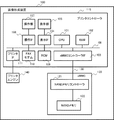
図1は、本発明の実施形態に係る画像形成装置100のハードウェア構成を説明するブロック図である。
FIG. 1 is a block diagram for explaining a hardware configuration of an
プリンタコントローラ(制御部)115は、バス130を介してeMMC(embedded Multi Media Card)120と接続されている。eMMC120は、フラッシュメモリを利用した組み込み機器用の不揮発記憶装置で、NANDフラッシュメモリと制御回路とを一つのパッケージにまとめ、MMC(マルチメディアカード)と同じインターフェースで接続される。プリンタコントローラ115eMMC(embedded Multi Media Card )のCPU101は、プリンタコントローラ115全体を制御するCPUであり、RAM102に展開されたプログラムを実行して各種の演算なども行う。RAM102はCPU101が動作するためのシステムワークメモリを提供し、CPU101がeMMC120などからデータやプログラムをRAM102に展開し、そのプログラムに従って演算や各種制御などを実行する。eMMCコントローラIF(インタフェース)103は、CPU101の制御の下に、バス130を介してeMMC120へのアクセスをコントロールする。表示IF104は表示部105に接続されており、表示部105へ表示信号を送付する。表示部105は、表示パネルやLED等を含み、ユーザに情報を提示する。操作IF106は操作部107と接続されており、操作部107は、タッチパネルやボタンなどを含む。操作IF106は、操作部107から、タッチパネルやボタンなどを介したユーザの操作を電気信号として受け付ける。尚、表示部105がタッチパネル機能を有している場合、表示部105と操作部107は一体に形成される。
The printer controller (control unit) 115 is connected to an eMMC (embedded Multi Media Card) 120 via a
ROM109は、起動用プログラムや、出荷時データや、更には、図2を参照して後述するユーザデータ初期化フラグを保存する不揮発メモリで、例えばフラッシュROMである。FAXモデム110はFAXデータの送受信を行うモデムで、不図示の電話回線と接続されている。FAX受信データは、一旦、eMMC120にFAX受信画像データファイルとして保存され、FAX送信データも一時、FAX送信画像データファイルとしてeMMC120に保存される。プリンタIF111は、プリンタエンジン140と接続され、プリンタエンジン140にプリントデータやプリンタ制御コマンドを送付したり、プリンタエンジン140からレスポンスを受信する。これらの各部は、バス108を介して互いに接続されている。
The
eMMC120は、上述の制御回路であるNANDメモリコントローラ121、NANDメモリ(NANDフラッシュメモリ)122を有している。NANDメモリコントローラ121は、バス130を介してeMMCコントローラIF103と接続されている。NANDメモリコントローラ121は、eMMCコントローラIF103からコマンドを受信し、受信したコマンドに応じて、データやレスポンスをeMMCコントローラIF103にバス130を介して送付する。ここで受信するコマンドは、安全消去コマンドや書き込みコマンド、読み込みコマンドなどを含む。NANDメモリコントローラ121は、NANDメモリ122と接続されており、eMMCコントローラ103から受信したコマンドを解釈する。安全消去コマンドの場合は、NANDメモリ122に記録しているデータを安全に消去し、書き込みコマンドの場合には、eMMCコントローラIF103からバス130を介して受信したデータをNANDメモリ122に書き込む。また読み込みコマンドの場合、NANDメモリコントローラ121は、NANDメモリ122からデータの読み込みを行い、その読み込んだデータをバス130を介してプリンタコントローラ115に送信する。
The eMMC 120 includes a NAND memory controller 121 and a NAND memory (NAND flash memory) 122, which are the control circuits described above. The NAND memory controller 121 is connected to the eMMC controller IF 103 via the
またeMMC120は、データの書換えを記憶媒体の記憶素子にできる限り均等にするウエアレベリング機能を有し、NANDメモリ122の特定の物理アドレスに集中してデータの書き込みが発生しないように制御する。eMMC120は、NANDメモリコントローラ121が書き込みコマンドを受けると、そのコマンドに含まれる論理アドレス情報を解析し、実際に書き込まれるNANDメモリ122の物理アドレスを探しだす。そして、その探し出した物理アドレスの書き込み回数と、他の使用していない物理アドレスのメモリの書き込み回数とを比較し、書き込み回数の少ない物理アドレスのメモリへの書き込みを実行する。このようにNANDメモリコントローラ121は、論理アドレスに対応する物理アドレスにデータを書き込む。そのため、eMMCコントローラIF103からeMMC120に対して、同じ論理アドレスを指示して上書きするための書き込みコマンドを発行しても、そのアドレスに上書きされずにデータが残ってしまうことがある。また論理アドレスに対応しない物理アドレスのデータは、上書きされずにNANDメモリ122に残ってしまうことになる。
The eMMC 120 also has a wear leveling function to equalize rewriting of data to the storage elements of the storage medium as much as possible, and controls so that writing of data does not occur concentrated on a specific physical address of the
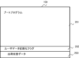
図2は、本実施形態に係る画像形成装置100のROM109に記憶されているデータを説明する図である。
FIG. 2 is a view for explaining data stored in the
このROM109にはブートプログラム201が記憶されており、ここには、この画像形成装置100の起動プログラムが格納されている。CPU101は起動すると、最初にこのブートプログラム201を読み出して実行する。CPU101は、このブートプログラム201を実行することによって、eMMC120からデータやプログラムを読み込んでRAM102に展開し、そのプログラムを実行できるようになる。ユーザデータ初期化フラグ202は、ユーザデータを初期化するかどうかを示すフラグであり、ユーザがユーザデータの初期化を実行するときは、このフラグ202がオンに設定される。出荷状態データ203は、工場出荷時の初期設定データを保存する領域であり、工場出荷時に、この領域に工場出荷時の設定データが書き込まれる。
The
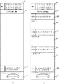
図3〜図5は、実施形態に係る画像形成装置100におけるeMMC120のデータの配置の遷移を説明する図である。
3 to 5 are diagrams for explaining the transition of data arrangement of the
図3(A)は、ユーザが画像形成装置100をある程度使用した後のeMMC120の内部データの配置を示す図である。
FIG. 3A shows the arrangement of internal data of the
CPU101は、ブートプログラム201を実行して、プログラム保存領域302からプログラムを読み込み、そのプログラムをRAM102に展開して実行する。eMMC120には、マスタブートレコード301(以下、MBR)の領域があり、ここにはeMMC120のデータの複数のパーティション情報を示すデータが記録されている。このパーティション情報には、どのアドレスからパーティションが開始されるかを示すデータが記録されており、CPU101は、このデータに基づいてパーティションを認識する。実施形態では、MBR301には、パーティションブートレコード1〜4の4つのパーティションが記録されている。ここでパーティションブートレコード1はPBR1(303)、パーティションブートレコード2はPBR2(305)、パーティションブートレコード3はPBR3(307)、パーティションブートレコード4はPBR4(309)で示されている。
The
CPU101が実行するプログラムは、MBR301を読み出し、MBR301に書き込まれているパーティション情報から、PBR1(303)、PBR2(305)、PBR3(307)、PBR4(309)の先頭アドレスを読み出す。こうしてパーティションが存在することを確認し、これらのパーティションをソフトウエア的に利用可能にする。これらの処理は一般的にボリュームのマウントと呼ばれている。
The program executed by the
PBR1(303),PBR2(305),PBR3(307),PBR4(309)には、そのパーティションで管理するデータ領域のスタートアドレスとサイズが記述されている。また、そのパーティションで管理するファイルやフォルダの情報を記述するデータ領域も記録されている。ファイルやフォルダの削除は、このファイルやフォルダの情報を記述しているデータを削除状態とすることにより実行される。従って、このとき実際のファイルデータやフォルダデータを削除していない。そのため、ファイルやフォルダを削除したとしても、このファイルやフォルダの情報を元に戻すことによって、ファイルやフォルダを復元することが可能である。 In PBR1 (303), PBR2 (305), PBR3 (307), and PBR4 (309), the start address and the size of the data area managed by the partition are described. In addition, a data area that describes information of files and folders managed by the partition is also recorded. Deletion of a file or folder is performed by setting data describing the information of the file or folder as a deletion state. Therefore, the actual file data and folder data are not deleted at this time. Therefore, even if the file or folder is deleted, the file or folder can be restored by restoring the information on the file or folder.
図3(A)のMBR301のパーティション1〜4には、各対応するPBR1(303)〜PBR4(309)の先頭アドレスが記憶されている。PBR1(303)には、ルートフォルダ名が「FAXデータ」で、ファイルとして「FAX受信データ」、「FAX送信データ」が記述されている。ルートフォルダ名は、対象のパーティションの一番上位のフォルダ名であり、そのパーティション名でもある。パーティションの一番上位のフォルダ名は、一般的には「C:」などの名前が付けられており、Cドライブなどと呼ばれることも多い。図3(A)の例では、FAXデータ領域304には、FAX受信データファイル311とFAX送信データファイル312が記憶されている。
The top addresses of the corresponding PBR1 (303) to PBR4 (309) are stored in partitions 1 to 4 of the
PBR2(305)はルートフォルダ名が「プリントデータ」であり、図3(A)の例では、プリントデータ領域306にプリントデータのファイルは存在していない。
The root folder name of PBR 2 (305) is “print data”, and in the example of FIG. 3A, no print data file exists in the
PBR3(307)はルートフォルダ名が「ユーザデータ」であり、ファイルには、「ユーザデータ」と「カウンタ」がある。図3(A)の例では、ユーザデータ領域308には、ユーザ設定データが書き込まれたユーザデータファイル313と、印刷を実行した総印刷枚数などを記録しているカウンタファイル314が記憶されている。
The PBR 3 (307) has a root folder name "user data", and the file has "user data" and "counter". In the example of FIG. 3A, the
PBR4(309)はルートフォルダ名が「バックアップ」であり、図3(A)では、バックアップ領域310には、バックアップするファイルは存在していない。
The root folder name of the PBR 4 (309) is "backup", and the file to be backed up does not exist in the
この状態で、パーティションブートレコードPBR1〜PBR4のデータを削除すると、そのパーティションで管理されているデータ領域のデータが削除されていなくても、CPU101が実行するプログラムはそのパーティションにはデータがないと判断する。
In this state, if the data in the partition boot records PBR1 to PBR4 is deleted, the program executed by the
図3(B)は、eMMC120のデータを削除するための準備を説明する図である。
FIG. 3B is a diagram for explaining preparation for deleting data of the
ユーザがeMMC120のデータの初期化を実行すると、CPU101は、eMMCコントローラIF103を介して、ユーザデータ領域308のカウンタファイル314をeMMC120から読み出してRAM102に一時保存する。そして、RAM102に保存したデータの総印刷枚数を除く、FAXデータ領域304、プリントデータ領域306、ユーザデータ領域308を全て初期化する。その後、PBR4(309)が管理するバックアップ領域310に、クリアカウンタファイル315を保存する。こうしてPBR4のバックアップ領域310には、クリアカウンタファイル315が記憶される。このときPBR4(309)のルートフォルダ名が「バックアップ」、ファイルは「クリアカウンタ」となっている。
When the user executes initialization of data of the
図4(A)は、eMMC120のFAXデータ領域、プリントデータ領域、ユーザデータ領域を削除した後のデータの配置を示す図である。
FIG. 4A is a diagram showing the arrangement of data after the FAX data area, the print data area, and the user data area of the
図4(A)では、図3(B)で説明した通り、CPU101は、バックアップ領域310にクリアカウンタファイル315を保存した後、eMMCコントローラIF103を介して、eMMC120のPBR1〜3のデータを全て消去する。このとき、PBR1〜3が管理するメモリアドレス領域のデータと、論理アドレスに対応しない物理アドレスのデータを物理的に消去する。この処理により、PBR1〜3(303,305,307)に記憶されているファイル情報やフォルダ情報と、ユーザデータ領域308のユーザ設定データが記憶されているユーザデータファイル313を確実に削除できる。更に、FAXデータ領域304のFAX受信データファイル311、FAX送信データファイル312を確実に削除できる。尚、図3ではプリントデータ領域306にプリントデータファイルが存在していないが、存在していていれば、そのプリントデータファイルも確実に削除できる。
In FIG. 4A, as described in FIG. 3B, the
図4(B)は、eMMC120のMBR301、プログラム保存領域302、PBR4(309)及びバックアップ領域310以外のデータを全て削除した後、eMMC120のパーティションを復元したときのデータ領域を示す図である。ここでは図3と共通する部分は同じ参照番号で示している。
FIG. 4B is a diagram showing a data area when the partition of the
CPU101は、eMMCコントローラIF103を介して、eMMC120からMBR301を読み取ってパーティション情報を確認する。そしてCPU101は、MBR301のパーティション情報に基づいて、PBR1,PBR2,PBR3,PBR4を読み取ろうとする。しかしこのときPBR1,PBR2,PBR3がないため、パーティションがないと判断し、これらパーティションを復元する。このパーティションの復元では、MBR301の情報を基に、図3(A)のように、PBR1,PBR2,PBR3を作成する。尚、このパーティションの復元は、パーティション情報をプログラム保存領域302のプログラムや、ブートプログラム201のプログラムが保持しているパーティション情報から復元してもよい。これらのパーティションを復元した後、これらのパーティションをソフトウェア的に利用可能にする。
The
図5は、eMMC120のパーティションを復元した後、更にユーザデータを復元した状態を示す図である。
FIG. 5 is a diagram showing a state in which user data is further restored after the
CPU101は、プログラム保存領域302に保存されているプログラム、或いは、ブートプログラム201に保存されているプログラムに従って、図2で示す出荷状態データ203に保存されている出荷状態の設定データをRAM102に展開する。こうして展開された設定データからファイルを作成し、eMMCコントローラIF103を介して、PBR3(307)が管理するユーザデータ領域308にユーザデータファイル319として保存する。
The
またCPU101は、図3(B)でクリアされ、バックアップ領域310に保存されているクリアカウンタファイル315を読み取ってRAM102に展開する。こうしてRAM102に展開したクリアカウンタファイル315を、復元したパーティション情報であるPBR3(307)が管理するユーザデータ領域308にカウンタファイル320として書き込む。つまりバックアップ領域310のクリアカウンタファイル315を別名でユーザデータ領域308に保存する。こうしてユーザデータ領域308にカウンタファイル320を保存した後、バックアップ領域310のクリアカウンタファイル315を削除する。この削除処理では、PBR4(309)のファイル情報を初期化して、クリアカウンタファイルを削除状態とする。このため、クリアカウンタファイル315は、PBR4(309)が管理するバックアップ領域310に残った状態となる。よって、安全のためにPBR4(309)が管理するバックアップ領域310とPBR4(309)のデータと、論理アドレスに対応しない物理アドレスのデータを物理的に消去する。そして、図4(B)で説明したように、PBR4のパーティションを復元するようにしてもよい。
Further, the
これらの処理により、eMMC120のデータは工場出荷状態となり、かつ、この装置の使用履歴を示す総印刷枚数は、初期化される前の情報でカウンタファイル320として保存される。これらの処理が終了した後、ROM109のユーザデータ初期化フラグ202をオフにする。
As a result of these processes, the data of the
図6は、本実施形態に係る画像形成装置100のプリンタコントローラ115がeMMC120のデータを初期化する処理を説明するフローチャートである。尚、この処理を実行するプログラムは、例えばeMMC120のプログラム保存領域302に記憶されており、実行時、CPU101がそのプログラムをRAM102に展開して実行することにより、このフローチャートで示す処理が達成される。この処理は、例えば、ユーザが操作部107を介して、eMMC120のデータの初期化処理を指示することにより開始される。
FIG. 6 is a flow chart for explaining the process in which the
この処理が開始されるとまずS601でCPU101は、印刷ジョブなどのジョブを実行中、或いは待機中かどうかを判定する。ここで印刷ジョブなどを実行中、或いはジョブの実行待ちの場合はS602に進み、CPU101は、表示部105にジョブが存在しているため初期化処理が実施できない旨を表示して、この処理を終了する。S602で表示される画面例を図8(A)に示す。
When this process is started, in step S601, the
一方、S601でCPU101は、実行中或いは実行待ちのジョブがないと判定した場合はS603に進み、CPU101は、eMMC120のデータの初期化処理中にジョブを受信しないようにジョブの受付けを禁止する。次にS604に進みCPU101は、eMMC120のデータの初期化中である旨を表示部105に表示して、eMMC120のデータの初期化が実行中であることをユーザに知らせる。S604で表示される画面例を図8(B)に示す。
On the other hand, if the
次にS605に進みCPU101は、図3(B)を参照して説明したように、PBR3のユーザデータ領域308のデータを読み出し、総印刷枚数などの画像形成装置100がどの程度使用されたかを示すカウンタファイル以外を初期化する。そしてその初期化したデータをRAM102に保存する。このとき初期化されたユーザデータファイルのデータは、復元時、プログラム保存領域302に保存されている値か、出荷状態データ203に保存されているデータを使用する。そしてS605で、このデータの初期化に成功したかどうかを判定し、初期化に成功したと判定するとS607に進むが、そうでないときはS606に進み、初期化に失敗したしたことを表示部105に表示して、この処理を終了する。S606で表示される画面例を図8(C)に示す。
Next, in step S605, as described with reference to FIG. 3B, the
S607でCPU101は、カウンタファイル314から、総印刷枚数などの、この画像形成装置100がどの程度使用されたかを示すデータ以外を初期化したクリアカウンタファイル315を作成する。そしてカウンタファイル314が保存されているパーティションとは別のeMMC120に設定されているパーティションに保存する。図3(B)では、PBR4のバックアップ領域310に保存している。尚、ここで、初期化したクリアカウンタファイル315をeMMC120に書き込まずに、RAM102に保存したままにすることも考えられる。そしてCPU101は、カウンタファイル314の初期化とクリアカウンタファイル315の作成に成功したかどうか判定し、成功したときはS609に進む。一方、成功していないときはS608に進み、バックアップファイルの作成に失敗したしたことを表示部105に表示して、この処理を終了する。S608で表示される画面例を図8(C)に示す。
In step S607, the
S609でCPU101は、ROM109の出荷状態データ203に保存されている工場出荷時の設定データが正しいかどうか判定する。このデータが正しいかどうかの判定方法は公知のものでよく、電子署名の確認やチェックサムのチェックなどが考えられる。ここでCPU101が、データが正しいと判定するとS611に進む。一方、データが正しくないと判定するとS610に進み、CPU101は表示部105に、ユーザ記録データの初期化処理が失敗したことを表示して、この処理を終了する。S610で表示される画面例を図8(C)に示す。
In step S609, the
S611でCPU101は、ROM109のユーザデータ初期化フラグ202をオンにする。このユーザデータ初期化フラグ202をオンにすることにより、この後の処理中に何らかの原因で電源がオフされても、起動時にこのフラグ202がオンであれば、ユーザ記録データの初期化を、後述するS613の起動画面の表示処理から再実行できる。こうしてeMMC120に保存したデータの削除中に何らかの問題が発生した場合でも、初期化処理を再実行できるようになる。
In step S611, the
次にS612に進みCPU101は、プリンタコントローラ115を再起動してS613に進む。ここでは、S607で初期化したクリアカウンタファイル315をeMMC120に保存せずにRAM102に保存したままの場合は、再起動せずにS617に進む。S613でCPU101は、起動中を示す画面を表示部105に表示する。S613で表示される起動画面例を図8(D)に示す。尚、S613では、起動中を示す画面でなくても、S611で書き込んだユーザデータ初期化フラグ202を確認し、オンであればユーザデータの初期化を示す画面を表示するようにしてもよい。
Next, in step S612, the
次にS614に進みCPU101は、S611で書き込んだユーザデータ初期化フラグ202がオンかどうか判定し、オンであればS615に進み、オフであればそのままこの処理を終了する。S615でCPU101は、S609と同様に、出荷状態データ203に保存されている工場出荷時の設定データが正しいかどうかを判定する。ここでCPU101は、工場出荷時の設定データが正しいと判定した場合はS617に進むが、正しくないと判定した場合はS616に進み、表示部105にユーザ記録データ初期化の処理が失敗した事を示して終了する。尚、S616では、ユーザ記録データの初期化処理を再実行しないように、ユーザデータ初期化フラグ202をオフにしてから終了してもよい。S616で表示される画面例を図8(C)に示す。
Next, in step S614, the
S617でCPU101は、eMMC120のPBR1,PBR2,PBR3で管理されている領域のデータと、論理アドレスに対応しない物理アドレスのデータを図4(A)を参照して説明したように物理的に完全に消去する。即ち、図4(A)に示すように、PBR1,PBR2,PBR3のパーティションとそのデータを完全に削除する。次にS618に進みCPU101は、図4(B)を参照して説明したように、eMMC120のMBR301を参照して、eMMC120のパーティションを復元してS619に進む。
In step S617, the
S619でCPU101は、工場出荷時のデータをROM109内部の出荷状態データ203から読み出し、ユーザデータファイル319としてS618で復元されたPBR3(307)が管理するパーティションに書き込む(図5参照)。そしてCPU101は、工場出荷時のユーザデータファイル319の書き戻しが成功したと判定するとS621に進むが、そうでないときはS620に進み、表示部105にユーザ記録データの初期化に失敗した旨を表示して終了する。S620で表示される画面例を図8(C)に示す。
In step S619, the
S621でCPU101は、S607で保存したカウンタファイルであるクリアカウンタファイル315を、S618で復元したPBR3のパーティションに書き戻す。そしてCPU101は、カウンタファイルの書き戻しに成功したと判定したときはS623に進むが、そうでないときはS622に進み、表示部105にユーザ記録データの初期化が失敗した旨を表示して、この処理を終了する。S622で表示される画面例を図8(C)に示す。
In step S621, the
S623でCPU101は、PBR4のバックアップ領域310のクリアカウンタファイル315を削除する。ここでは安全のため、PBR4(309)が管理するバックアップ領域310のデータと、このパーティションの論理アドレスに対応しない物理アドレスのデータとを物理的に完全消去した後、PBR4が管理するパーティションを復元してもよい。これらの処理により、eMMC120のデータは工場出荷状態で、かつ、この装置の使用履歴を示す総印刷枚数は、初期化する前の元の情報に復帰される。そしてS624でCPU101は、ROM109のユーザデータ初期化フラグ202をオフにして、この処理を終了する。
At S623, the
図7は、本実施形態に係る画像形成装置100においてユーザ記録データの初期化を指示する画面例を示す図である。
FIG. 7 is a view showing an example of a screen for instructing initialization of user recording data in the
図7(A)は、ユーザ記録データの初期化を指示するためのメニュー画面であり、ユーザ記録データ初期化701をユーザが指示すると図7(B)の確認画面が表示される。図7(B)の画面で、ユーザが「はい」ボタン702を指示すると、ユーザ記録データの初期化処理が開始され、図6のフローチャートで示す処理が開始される。また「いいえ」ボタン703が指示されると、ユーザ記録データの初期化処理を実行せずに、そのまま終了する。
FIG. 7A is a menu screen for instructing initialization of user recording data, and when the user instructs initialization of
図8(A)は、本実施形態に係る画像形成装置100において、図6のS602で表示されるジョブ有りを示す画面例を示す図である。
FIG. 8A is a view showing an example of a screen indicating the presence of a job displayed in S602 of FIG. 6 in the
図6のS601でジョブなどの処理を実行しているか、もしくは、ジョブが実行待機中であるかどうかを判定し、ジョブがあると判定すると、S602に進み、例えば図8(A)に示すような画面を表示部105に表示する。
In step S601 in FIG. 6, it is determined whether processing such as a job is being executed or whether the job is waiting to be executed, and if it is determined that there is a job, the process proceeds to step S602, as shown in FIG. Is displayed on the
図8(B)は、本実施形態に係る画像形成装置100において、ユーザ記録データの初期化処理の実行中を示す画面例を示す図である。
FIG. 8B is a view showing an example of a screen showing that the user recording data initialization process is being performed in the
図6のS603でジョブの受け付けを禁止した後、S604で、ユーザにユーザ記録データの初期化処理を実行中であることを示すための、例えば図8(B)に示すような画面を表示部105に表示する。 After prohibiting the acceptance of the job in S603 of FIG. 6, the display unit as shown in FIG. 8B, for example, displays the screen to show that the user recording data initialization processing is being executed in S604. Displayed at 105.
図8(C)は、本実施形態に係る画像形成装置100において、図6のS606、S608、S610、S616、S620、S622で、ユーザデータの初期化に失敗したときに表示部105に表示する画面例を示す図である。尚、この画面に更に、失敗した原因やエラーの内容を示す情報を表示してもよい。
FIG. 8C is displayed on the
図8(D)は、本実施形態に係る画像形成装置100における、図6のS613で表示される起動画面の一例を示す図である。
FIG. 8D is a view showing an example of the start-up screen displayed in S613 of FIG. 6 in the
尚、S613で、このような起動画面を表示する代わりに、ユーザデータ初期化フラグ202がオンかどうか判断し、オンであればてユーザデータの初期化中であることを示す画面を表示してもよい。
In S613, instead of displaying such a start screen, it is determined whether or not the user
以上説明したように本実施形態によれば、不揮発記憶装置のデータを完全に初期化することができ、更に、装置の使用履歴を示す情報を初期化前の状態に戻すため、データの初期化後であっても新品の製品と区別できるようになる。 As described above, according to the present embodiment, data in the non-volatile storage device can be completely initialized, and furthermore, in order to return information indicating the usage history of the device to the state before initialization, the data is initialized It will be distinguishable from new products even afterward.
またデータの削除をパーティション単位で行うため、例えばウエアレベリング機能を採用することにより、データを書き込む論理アドレスと物理アドレスとが一致しない場合でも、その不揮発記憶装置内の消去対象のデータを確実に消去できる。 Further, since data deletion is performed in units of partitions, for example, by employing a wear leveling function, even if the logical address to which data is written and the physical address do not match, the data to be erased in the non-volatile storage device is reliably erased it can.
(その他の実施形態)
本発明は、上述の実施形態の1以上の機能を実現するプログラムを、ネットワーク又は記憶媒体を介してシステム又は装置に供給し、そのシステム又は装置のコンピュータにおける1つ以上のプロセッサーがプログラムを読出し実行する処理でも実現可能である。また、1以上の機能を実現する回路(例えば、ASIC)によっても実現可能である。
(Other embodiments)
The present invention supplies a program that implements one or more functions of the above-described embodiments to a system or apparatus via a network or storage medium, and one or more processors in a computer of the system or apparatus read and execute the program. Can also be realized. It can also be implemented by a circuit (eg, an ASIC) that implements one or more functions.
本発明は上記実施形態に制限されるものではなく、本発明の精神及び範囲から離脱することなく、様々な変更及び変形が可能である。従って、本発明の範囲を公にするために、以下の請求項を添付する。 The present invention is not limited to the above embodiments, and various changes and modifications can be made without departing from the spirit and scope of the present invention. Accordingly, the following claims are attached to disclose the scope of the present invention.
100…画像形成装置、101…CPU、102…RAM、105…表示部、107…操作部、109…ROM、120…eMMC、122…NANDメモリ、212…NANDメモリコントローラ、140…プリンタ
DESCRIPTION OF
Claims (10)
前記情報処理装置の設定データの初期値を記憶する記憶手段と、
前記不揮発記憶装置は複数のパーティションで管理されており、当該不揮発記憶装置の初期化が指示されると、前記設定データ及び前記情報処理装置の使用履歴を示すデータを記憶している第1パーティションから前記使用履歴を示すデータを保存する保存手段と、
前記複数のパーティションの内、前記初期化の対象となるデータを含むパーティションと当該パーティションに記憶されているデータを削除する削除手段と、
前記削除手段により削除された領域に、前記削除の前と同じパーティションを作成する作成手段と、
前記作成手段により作成されたパーティションの内、前記使用履歴を示すデータを記憶していた前記第1パーティションに、前記記憶手段に記憶されている前記設定データ及び前記保存手段により保存していた前記使用履歴を示すデータを書き込む書き込み手段と、
を有することを特徴とする情報処理装置。 An information processing apparatus having a non-volatile storage device,
Storage means for storing an initial value of the setting data of the information processing apparatus,
The non-volatile storage device is managed by a plurality of partitions, and when initialization of the non-volatile storage device is instructed, from the first partition storing the setting data and data indicating the usage history of the information processing apparatus Storage means for storing data indicating the usage history;
Among the plurality of partitions, the partition including the data to be initialized and the deleting means for deleting the data stored in the partition;
Creating means for creating the same partition as that before the deletion in the area deleted by the deletion means;
Among the partitions created by the creating means, the setting data stored in the storage means and the use saved by the saving means are stored in the first partition which stores data indicating the usage history. Writing means for writing data indicating a history;
An information processing apparatus comprising:
前記情報処理装置の設定データの初期値を記憶する記憶手段を有し、
前記CPUは、前記不揮発記憶装置のメモリを複数のパーティションで管理しており、当該不揮発記憶装置の初期化が指示されると、前記設定データ及び前記情報処理装置の使用履歴を示すデータを記憶している第1パーティションから前記使用履歴を示すデータを保存し、
前記CPUは、前記複数のパーティションの内、前記初期化の対象となるデータを含むパーティションと当該パーティションに記憶されているデータを削除し、
前記CPUは、前記データを削除した領域に、前記削除の前と同じパーティションを作成し、
前記CPUは、前記作成したパーティションの内、前記使用履歴を示すデータを記憶していた前記第1パーティションに、前記記憶手段に記憶されている前記設定データ及び保存していた前記使用履歴を示すデータを書き込むことを特徴とする情報処理装置。 An information processing apparatus having a CPU and a non-volatile storage device controlled by the CPU,
A storage means for storing an initial value of the setting data of the information processing apparatus,
The CPU manages the memory of the non-volatile storage device by a plurality of partitions, and stores the setting data and data indicating the usage history of the information processing device when initialization of the non-volatile storage device is instructed. Save data showing the usage history from the first partition,
The CPU deletes the partition including the data to be initialized and the data stored in the partition among the plurality of partitions.
The CPU creates the same partition as before the deletion in the area from which the data is deleted,
Wherein the CPU, among the created partition, the first partition that has stored the data indicating the use history, indicating the use history of the had set data and save stored in the storage means An information processing apparatus characterized by writing data.
前記不揮発記憶装置を複数のパーティションで管理し、
前記不揮発記憶装置の初期化が指示されると、設定データ及び前記情報処理装置の使用履歴を示すデータを記憶している第1パーティションから前記使用履歴を示すデータを保存し、
前記複数のパーティションの内、前記初期化の対象となるデータを含むパーティションと当該パーティションに記憶されているデータを削除し、
前記削除された領域に、前記削除の前と同じパーティションを作成し、
前記作成されたパーティションの内、前記使用履歴を示すデータを記憶していた前記第1パーティションに、前記情報処理装置の設定データの初期値を記憶する記憶部に記憶されている前記設定データ及び前記保存していた前記使用履歴を示すデータを書き込むことを特徴とする初期化方法。 A method of initializing a non-volatile storage device by an information processing apparatus having a non-volatile storage device, comprising:
Managing the non-volatile storage device by a plurality of partitions;
Wherein the initialization of the non-volatile memory device is instructed to save the data indicating the use history from the first partition that stores data indicating the use history of the configuration data and the information processing apparatus,
Among the plurality of partitions, the partition including the data to be initialized and the data stored in the partition are deleted.
Create the same partition as before the deletion in the deleted area,
Among the created partition, the said data indicating the use history has stored the first partition, the setting data stored in the storage unit for storing the initial value of the setting data of the information processing apparatus and Writing data indicating the usage history that has been stored.
Priority Applications (2)
| Application Number | Priority Date | Filing Date | Title |
|---|---|---|---|
| JP2015143402A JP6543122B2 (en) | 2015-07-17 | 2015-07-17 | INFORMATION PROCESSING APPARATUS, METHOD OF INITIALIZING NONVOLATILE STORAGE DEVICE BY THE INFORMATION PROCESSING APPARATUS, AND PROGRAM |
| US15/200,093 US9930207B2 (en) | 2015-07-17 | 2016-07-01 | Information processing apparatus, method of initializing a non-volatile storage device, and storage medium |
Applications Claiming Priority (1)
| Application Number | Priority Date | Filing Date | Title |
|---|---|---|---|
| JP2015143402A JP6543122B2 (en) | 2015-07-17 | 2015-07-17 | INFORMATION PROCESSING APPARATUS, METHOD OF INITIALIZING NONVOLATILE STORAGE DEVICE BY THE INFORMATION PROCESSING APPARATUS, AND PROGRAM |
Related Child Applications (1)
| Application Number | Title | Priority Date | Filing Date |
|---|---|---|---|
| JP2019112126A Division JP6781803B2 (en) | 2019-06-17 | 2019-06-17 | Information processing device and its control method |
Publications (3)
| Publication Number | Publication Date |
|---|---|
| JP2017027244A JP2017027244A (en) | 2017-02-02 |
| JP2017027244A5 JP2017027244A5 (en) | 2018-08-23 |
| JP6543122B2 true JP6543122B2 (en) | 2019-07-10 |
Family
ID=57775332
Family Applications (1)
| Application Number | Title | Priority Date | Filing Date |
|---|---|---|---|
| JP2015143402A Active JP6543122B2 (en) | 2015-07-17 | 2015-07-17 | INFORMATION PROCESSING APPARATUS, METHOD OF INITIALIZING NONVOLATILE STORAGE DEVICE BY THE INFORMATION PROCESSING APPARATUS, AND PROGRAM |
Country Status (2)
| Country | Link |
|---|---|
| US (1) | US9930207B2 (en) |
| JP (1) | JP6543122B2 (en) |
Families Citing this family (7)
| Publication number | Priority date | Publication date | Assignee | Title |
|---|---|---|---|---|
| KR20170001221A (en) * | 2015-06-26 | 2017-01-04 | 에스프린팅솔루션 주식회사 | Image forming apparatus, data writing method of thereof and non-transitory computer readable recoding medium |
| JP2018185880A (en) * | 2017-04-27 | 2018-11-22 | 京セラドキュメントソリューションズ株式会社 | Electronic device |
| US10489162B2 (en) * | 2017-05-05 | 2019-11-26 | Dell Products L.P. | System and method of updating an information handling system via out-of-band data transfer |
| JP2019061458A (en) * | 2017-09-26 | 2019-04-18 | 京セラドキュメントソリューションズ株式会社 | Electronic device and log application |
| JP7134753B2 (en) * | 2018-07-10 | 2022-09-12 | キヤノン株式会社 | IMAGE FORMING APPARATUS, IMAGE FORMING APPARATUS CONTROL METHOD, AND PROGRAM |
| CN112817661A (en) * | 2021-02-23 | 2021-05-18 | 浙江大华技术股份有限公司 | Equipment configuration method and device and readable storage medium |
| US11947424B2 (en) * | 2022-04-15 | 2024-04-02 | Dell Products L.P. | Smart cataloging of excluded data |
Family Cites Families (18)
| Publication number | Priority date | Publication date | Assignee | Title |
|---|---|---|---|---|
| JP3215237B2 (en) * | 1993-10-01 | 2001-10-02 | 富士通株式会社 | Storage device and method for writing / erasing storage device |
| TW388832B (en) * | 1997-11-26 | 2000-05-01 | Seiko Epson Corp | Printing apparatus and its control method |
| US6516440B1 (en) * | 1998-05-14 | 2003-02-04 | Seiko Epson Corporation | Printer and a control method for saving data from volatile to nonvolatile memory in the printer |
| DE19839680B4 (en) * | 1998-09-01 | 2005-04-14 | Robert Bosch Gmbh | Method and device for modifying the memory contents of control units |
| US7146525B2 (en) * | 2001-08-31 | 2006-12-05 | Legend (Beijing) Limited | Method for backing up and recovering data in the hard disk of a computer |
| KR101115486B1 (en) * | 2003-08-08 | 2012-02-27 | 엘지전자 주식회사 | Apparatus and method for controlling booting of computer system |
| KR100584338B1 (en) * | 2003-09-17 | 2006-05-26 | 삼성전자주식회사 | Method and system for updating software |
| US20060080522A1 (en) * | 2004-10-13 | 2006-04-13 | Button Russell E | Method, apparatus, and system for facilitating secure computing |
| JP4479633B2 (en) | 2005-09-22 | 2010-06-09 | ヤマハ株式会社 | Audio equipment setting device and program thereof |
| JP2007272844A (en) * | 2006-03-31 | 2007-10-18 | Brother Ind Ltd | Peripheral device and data deletion authority management method |
| JP5078671B2 (en) * | 2008-02-28 | 2012-11-21 | キヤノン株式会社 | Information processing apparatus, information processing system, and information processing method |
| JP5091940B2 (en) * | 2009-12-28 | 2012-12-05 | 京セラドキュメントソリューションズ株式会社 | Image forming apparatus and nonvolatile memory writing method |
| JP5574858B2 (en) | 2010-07-07 | 2014-08-20 | キヤノン株式会社 | Information processing apparatus, control method for information processing apparatus, and program |
| JP5541194B2 (en) * | 2011-02-23 | 2014-07-09 | 株式会社デンソー | Control device for reading and writing data to flash memory |
| JP5729156B2 (en) * | 2011-06-20 | 2015-06-03 | カシオ電子工業株式会社 | Printing apparatus and printing method |
| WO2013048485A1 (en) * | 2011-09-30 | 2013-04-04 | Intel Corporation | Autonomous initialization of non-volatile random access memory in a computer system |
| KR101988260B1 (en) * | 2012-09-14 | 2019-06-12 | 삼성전자주식회사 | EMBEDDED MULTIMEDIA CARD(eMMC), AND METHOD FOR OPERATING THE eMMC |
| US20150178188A1 (en) * | 2013-12-20 | 2015-06-25 | Sandisk Technologies Inc. | Storage Module and Method for Re-Enabling Preloading of Data in the Storage Module |
-
2015
- 2015-07-17 JP JP2015143402A patent/JP6543122B2/en active Active
-
2016
- 2016-07-01 US US15/200,093 patent/US9930207B2/en active Active
Also Published As
| Publication number | Publication date |
|---|---|
| US9930207B2 (en) | 2018-03-27 |
| JP2017027244A (en) | 2017-02-02 |
| US20170019556A1 (en) | 2017-01-19 |
Similar Documents
| Publication | Publication Date | Title |
|---|---|---|
| JP6543122B2 (en) | INFORMATION PROCESSING APPARATUS, METHOD OF INITIALIZING NONVOLATILE STORAGE DEVICE BY THE INFORMATION PROCESSING APPARATUS, AND PROGRAM | |
| JP5746100B2 (en) | Image forming apparatus | |
| US9760461B2 (en) | Electronic device and firmware recovery program that ensure recovery of firmware | |
| JP4886866B2 (en) | Method for speeding up access to main storage device and storage device system | |
| KR101813641B1 (en) | Image forming apparatus and method for booting the same having hibernation function | |
| TW202137002A (en) | Data storage device and method for maintaining normal boot operation of data storage device | |
| US20190265964A1 (en) | Electronic apparatus, updating method, and recording medium | |
| KR102429346B1 (en) | Memory Upgrade System And Method | |
| TW202223628A (en) | Data storage device and method for maintaining normal boot operation of data storage device | |
| JP2008009799A (en) | Image forming device | |
| JP6781803B2 (en) | Information processing device and its control method | |
| JP7401215B2 (en) | Information processing device, its control method and program | |
| JP7214381B2 (en) | IMAGE FORMING APPARATUS, IMAGE FORMING APPARATUS CONTROL METHOD AND PROGRAM | |
| JP6554881B2 (en) | Semiconductor device and storage medium control method | |
| JP7246869B2 (en) | IMAGE FORMING APPARATUS, IMAGE FORMING APPARATUS CONTROL METHOD AND PROGRAM | |
| JP2002175193A (en) | Device and method for rewriting program | |
| JP2007133512A (en) | Information processor with flash rom, and data erasing method for flash rom | |
| JP7134753B2 (en) | IMAGE FORMING APPARATUS, IMAGE FORMING APPARATUS CONTROL METHOD, AND PROGRAM | |
| US10447886B2 (en) | Image processing apparatus for updating a non-volatile memory and method controlling image processing apparatus | |
| JP2017142754A (en) | Information processing device and control method thereof, and program | |
| JP2001344156A (en) | Device with flash memory and data rewriting method | |
| JP2008009494A (en) | Image forming device | |
| CN113918199A (en) | Method for updating underlying firmware program, storage medium and electronic device | |
| JPH11232183A (en) | Printer control information managing device and recording medium for recording control information management program | |
| JP5707870B2 (en) | Information processing apparatus and storage medium |
Legal Events
| Date | Code | Title | Description |
|---|---|---|---|
| A521 | Request for written amendment filed |
Free format text: JAPANESE INTERMEDIATE CODE: A523 Effective date: 20180713 |
|
| A621 | Written request for application examination |
Free format text: JAPANESE INTERMEDIATE CODE: A621 Effective date: 20180713 |
|
| A977 | Report on retrieval |
Free format text: JAPANESE INTERMEDIATE CODE: A971007 Effective date: 20190507 |
|
| TRDD | Decision of grant or rejection written | ||
| A01 | Written decision to grant a patent or to grant a registration (utility model) |
Free format text: JAPANESE INTERMEDIATE CODE: A01 Effective date: 20190517 |
|
| A61 | First payment of annual fees (during grant procedure) |
Free format text: JAPANESE INTERMEDIATE CODE: A61 Effective date: 20190614 |
|
| R151 | Written notification of patent or utility model registration |
Ref document number: 6543122 Country of ref document: JP Free format text: JAPANESE INTERMEDIATE CODE: R151 |