JP6541640B2 - Software configurable manipulator freedom - Google Patents
Software configurable manipulator freedom Download PDFInfo
- Publication number
- JP6541640B2 JP6541640B2 JP2016502600A JP2016502600A JP6541640B2 JP 6541640 B2 JP6541640 B2 JP 6541640B2 JP 2016502600 A JP2016502600 A JP 2016502600A JP 2016502600 A JP2016502600 A JP 2016502600A JP 6541640 B2 JP6541640 B2 JP 6541640B2
- Authority
- JP
- Japan
- Prior art keywords
- manipulator
- joint space
- joint
- freedom
- tool
- Prior art date
- Legal status (The legal status is an assumption and is not a legal conclusion. Google has not performed a legal analysis and makes no representation as to the accuracy of the status listed.)
- Active
Links
Images


Classifications
-
- B—PERFORMING OPERATIONS; TRANSPORTING
- B25—HAND TOOLS; PORTABLE POWER-DRIVEN TOOLS; MANIPULATORS
- B25J—MANIPULATORS; CHAMBERS PROVIDED WITH MANIPULATION DEVICES
- B25J9/00—Programme-controlled manipulators
- B25J9/16—Programme controls
- B25J9/1694—Programme controls characterised by use of sensors other than normal servo-feedback from position, speed or acceleration sensors, perception control, multi-sensor controlled systems, sensor fusion
-
- A—HUMAN NECESSITIES
- A61—MEDICAL OR VETERINARY SCIENCE; HYGIENE
- A61B—DIAGNOSIS; SURGERY; IDENTIFICATION
- A61B34/00—Computer-aided surgery; Manipulators or robots specially adapted for use in surgery
- A61B34/30—Surgical robots
- A61B34/35—Surgical robots for telesurgery
-
- A—HUMAN NECESSITIES
- A61—MEDICAL OR VETERINARY SCIENCE; HYGIENE
- A61B—DIAGNOSIS; SURGERY; IDENTIFICATION
- A61B34/00—Computer-aided surgery; Manipulators or robots specially adapted for use in surgery
- A61B34/30—Surgical robots
-
- A—HUMAN NECESSITIES
- A61—MEDICAL OR VETERINARY SCIENCE; HYGIENE
- A61B—DIAGNOSIS; SURGERY; IDENTIFICATION
- A61B34/00—Computer-aided surgery; Manipulators or robots specially adapted for use in surgery
- A61B34/30—Surgical robots
- A61B34/37—Master-slave robots
-
- G—PHYSICS
- G05—CONTROLLING; REGULATING
- G05B—CONTROL OR REGULATING SYSTEMS IN GENERAL; FUNCTIONAL ELEMENTS OF SUCH SYSTEMS; MONITORING OR TESTING ARRANGEMENTS FOR SUCH SYSTEMS OR ELEMENTS
- G05B19/00—Programme-control systems
-
- A—HUMAN NECESSITIES
- A61—MEDICAL OR VETERINARY SCIENCE; HYGIENE
- A61B—DIAGNOSIS; SURGERY; IDENTIFICATION
- A61B34/00—Computer-aided surgery; Manipulators or robots specially adapted for use in surgery
- A61B34/20—Surgical navigation systems; Devices for tracking or guiding surgical instruments, e.g. for frameless stereotaxis
- A61B2034/2046—Tracking techniques
- A61B2034/2059—Mechanical position encoders
Landscapes
- Health & Medical Sciences (AREA)
- Engineering & Computer Science (AREA)
- Surgery (AREA)
- Life Sciences & Earth Sciences (AREA)
- Robotics (AREA)
- Molecular Biology (AREA)
- General Health & Medical Sciences (AREA)
- Biomedical Technology (AREA)
- Heart & Thoracic Surgery (AREA)
- Medical Informatics (AREA)
- Veterinary Medicine (AREA)
- Animal Behavior & Ethology (AREA)
- Nuclear Medicine, Radiotherapy & Molecular Imaging (AREA)
- Public Health (AREA)
- Mechanical Engineering (AREA)
- Physics & Mathematics (AREA)
- General Physics & Mathematics (AREA)
- Automation & Control Theory (AREA)
- Manipulator (AREA)
- Human Computer Interaction (AREA)
Description
(関連出願の参照)
本出願は2013年3月15日に出願された米国仮出願第61/793,093号の35USC119(e)の下の利益を主張する。全ての目的のために、その全開示をここに参照として援用する。
(Refer to related application)
This application claims the benefit under 35 USC 119 (e) of US Provisional Application No. 61 / 793,093, filed March 15, 2013. The entire disclosure is incorporated herein by reference for all purposes.
本出願は、以下の同一所有者による出願、即ち、2012年8月15日に出願された「Phantom Degrees of Freedom for Manipulating the Movement of Robotic Systems」という名称の米国仮出願第61/683,495号、2012年6月1日に出願された「Commanded Reconfiguration of a Surgical Manipulator Using the Null Space」という名称の米国仮出願第61/654,764号、2009年6月30日に出願された「Control of Medical Robotic System Manipulator About Kinematic Singularities」という名称の米国出願第12/494,695号(許可済み)、2009年3月17日に出願された「Master Controller Having Redundant Degrees of Freedom and Added Forces to Create Internal Motion」という名称の米国出願第12/406,004号(今や米国特許第8,271,130号)、2005年5月19日に出願された「Software Center and Highly Configurable Robotic Systems for Surgery and Other Use」という名称の米国出願第11/133,423号(今や米国特許第8,004,229号)、2004年9月30日に出願された「Offset Remote Center Manipulator For Robotic Surgery」という名称の米国出願第10/957,077号(今や米国特許第7,594,912号)、1999年9月17日に出願された「Master Having Redundant Degrees of Freedom」という名称の米国出願第09/398,507号(今や米国特許第6,714,839号)に概ね関連し、それらの全開示をここに参照として援用する。 This application is filed by the same common owner, namely US Provisional Application No. 61 / 683,495, filed on August 15, 2012, entitled "Phantom Degrees of Freedom for Manipulating the Movement of Robotic Systems" US Provisional Application No. 61 / 654,764, filed Jun. 1, 2012, entitled “Commanded Reconfiguration of a Surgical Manipulator Using the Null Space”, filed Jun. 30, 2009, “Control of No. 12 / 494,695 (approved) entitled Medical Robotic System Manipulator About Kinematics, filed on March 17, 2009, entitled "Master Controller Having Redundant Degrees of Freedom and Added Forces to Create Internal Motion" U.S. application Ser. No. 12 / 406,004 (now U.S. Pat. No. 8,271,130), entitled US Application No. 11 / 133,423 entitled “Software Center and Highly Configurable Robotic Systems for Surgery and Other Use” filed May 19, 2005 (now US Patent No. 8,004,229), 2004 No. 10 / 957,077 entitled “Offset Remote Center Manipulator For Robotic Surgery” filed on September 30, 2012 (now US Pat. No. 7,594,912), September 17, 1999 No. 09 / 398,507, now entitled "Master Having Redundant Degrees of Freedom" (now U.S. Pat. No. 6,714,839), the entire disclosure of which is incorporated herein by reference. Do.
本発明は、改良された手術及び/又はロボット装置、システム、及び方法を概ね提供する。 The present invention generally provides improved surgical and / or robotic devices, systems and methods.
最小侵襲的な医療技法は、診断又は外科処置中に損傷させられる外部組織の量を減少させ、それにより、患者の回復時間、不快さ、及び有害な副作用を減少させることを目指している。何百万もの手術が米国内で毎年執り行われる。これらの手術の多くは潜在的には最小侵襲的な方法において執り行われる。しかしながら、最小侵襲的な手術器具及び技法の制約並びにそれらを習得するのに要する追加的な手術訓練の故に、比較的少数の手術のみがこれらの技法を現在用いている。 Minimally invasive medical techniques aim to reduce the amount of external tissue damaged during diagnosis or surgery, thereby reducing the patient's recovery time, discomfort and adverse side effects. Millions of surgeries are performed each year in the United States. Many of these procedures are performed in a potentially minimally invasive manner. However, due to the limitations of minimally invasive surgical instruments and techniques and the additional surgical training required to acquire them, only a relatively small number of procedures currently use these techniques.
手術における使用のための最小侵襲的な遠隔手術システムが開発されて、外科医の器用さを増大させ、外科医が遠隔場所から患者を手術するのを可能にしている。遠隔手術は手術システムの一般用語であり、遠隔手術では、外科医は、手術器具を手で直接的に保持して移動させるのではなくむしろ、何らかの形態の遠隔制御、例えば、サーボ機構又は同種の機構を用いて手術器具を操作する。そのような遠隔手術システムにおいて、外科医は遠隔場所で手術部位の画像(イメージ)が提供される。手術部位の典型的には三次元画像を適切なビューア又はディスプレイ上で見ながら、外科医はマスタ制御入力装置を操作することによって患者に対する手術を行い、次いで、マスタ制御入力装置はロボット器具の運動を制御する。小さな最小侵襲的な手術孔を通じてロボット手術器具を挿入し、患者内の手術部位で組織を治療し、そのような手術孔は典型的には開放手術(観血手術)に関連する外傷を招く。これらのロボットシステムは、多くの場合に、最小侵襲的な孔で器具のシャフトを旋回させること、孔を通じて軸方向にシャフトを摺動させること、孔内でシャフトを回転させること、及び/又は同種の操作によって、十分な器用さで手術器具の作業端を移動させ、極めて複雑な手術タスクを遂行する。 Minimally invasive telesurgical systems for use in surgery have been developed to increase the dexterity of the surgeon and allow the surgeon to operate the patient from a remote location. Telesurgery is a general term for surgical systems, in which the surgeon does not directly hold and move the surgical instrument by hand, rather than some form of remote control, such as a servo mechanism or similar mechanism Operate the surgical instrument using. In such telesurgery systems, the surgeon is provided with an image of the surgical site at a remote location. The surgeon performs the surgery on the patient by manipulating the master control input device, typically while viewing a three-dimensional image of the surgical site on a suitable viewer or display, and then the master control input device performs the motion of the robotic instrument Control. Robotic surgical instruments are inserted through small minimally invasive surgical holes to treat tissue at a surgical site in a patient, such surgical holes typically result in trauma associated with open surgery (open surgery). These robotic systems often pivot the shaft of the tool in a minimally invasive bore, slide the shaft axially through the bore, rotate the shaft within the bore, and / or the like. Operation moves the working end of the surgical instrument with sufficient dexterity to perform extremely complex surgical tasks.
遠隔手術のために用いられるサーボ機構は、多くの場合に、2つのマスタコントローラ(各1つが外科医の各々の手のためにある)を受容し、2つ又はそれよりも多くのロボットアーム又はマニピュレータを含むことがある。イメージキャプチャデバイス(画像捕捉装置)によって表示されるロボット器具の画像への手の動きのマッピングが、各々の手に関連する器具に対する正確な制御を外科医にもたらすのを助け得る。多くの手術ロボットシステムには、内視鏡又は他のイメージキャプチャデバイス、追加的な手術器具、又は同種のものを移動させるために、1つ又はそれよりも多くの追加的なロボット操作アームが含められる。 Servomechanisms used for telesurgery often receive two master controllers (one for each hand of the surgeon) and two or more robotic arms or manipulators May be included. The mapping of hand motion to the image of the robotic instrument displayed by the image capture device (image capture device) may help to provide the surgeon with precise control over the instrument associated with each hand. Many surgical robotic systems include one or more additional robotic control arms to move an endoscope or other image capture device, additional surgical instruments, or the like. Be
ロボット手術中に手術部位で手術器具を支持するために、様々な器具構成を用い得る。多くの場合に、被駆動リンク装置又は「スレーブ」をロボット手術マニピュレータと呼び、最小侵襲的なロボット手術中のロボット手術マニピュレータとしての使用のための例示的なリンク装置構成が、2012年6月1日に出願された「Commanded Reconfiguration of a Surgical Manipulator Using the Null Space」という名称の米国仮出願第61/654,764号、米国特許出願第6,758,843号、第6,246,200号、及び第5,800,423号に記載されており、それらの全開示をここに参照として援用する。これらのリンク装置は、しばしば、平行四辺形構成を利用して、シャフトを有する器具を保持する。そのようなマニピュレータ構造は、器具シャフトが剛的なシャフトの長さに沿う空間内に位置付けられる球回転の遠隔中心について旋回するよう、器具の動きを制約し得る。(例えば、腹腔鏡手術中に腹壁でトロカール又はカニューレを用いて)この回転の中心を内部手術部位への切開地点と整列させることによって、腹壁に対して危険な力を加えずに、マニュピュレータリンク装置を用いてシャフトの近位端を移動させることにより、手術器具のエンドエフェクタを安全に位置付け得る。代替的なマニピュレータ構造は、例えば、米国特許第7,594,912号、6,702,805号、5,855,583号、5,808,665号、5,445,166号、及び5,184,601号に記載されており、それらの全開示をここに参照として援用する。 Various instrument configurations may be used to support the surgical instrument at the surgical site during robotic surgery. An example linkage arrangement for use as a robotic surgical manipulator during minimally invasive robotic surgery, often referred to as a driven linkage or "slave" as a robotic surgical manipulator, is 1 June 2012 Reconfiguration of a Surgical Manipulator Using the Null Space filed on the same day as US Provisional Application No. 61 / 654,764, US Patent Application No. 6,758,843, 6,246,200, And 5,800, 423, the entire disclosure of which is incorporated herein by reference. These linkages often utilize a parallelogram configuration to hold an instrument having a shaft. Such manipulator structures may constrain the movement of the instrument such that the instrument shaft pivots about the remote center of spherical rotation located in the space along the length of the rigid shaft. By aligning the center of this rotation with the incision point to the internal surgical site (eg, using a trocar or cannula at the abdominal wall during laparoscopic surgery), the manipulator link may be applied without dangerous force on the abdominal wall. By moving the proximal end of the shaft with the device, the end effector of the surgical instrument can be safely positioned. Alternative manipulator structures are described, for example, in U.S. Patent Nos. 7,594,912, 6,702,805, 5,855,583, 5,808,665, 5,445,166, and 5, No. 184,601, the entire disclosure of which is incorporated herein by reference.
新しいロボット手術システム及び装置は極めて効果的で有利であることが証明されているが、一層更なる改良が望ましい。ある場合には、マニピュレータアセンブリの一部又は全部を変更することが望ましい。その場合、マニピュレータアセンブリは、マニピュレータ(例えば、ロボットアーム)に接続されるツール(例えば、手術ツール)を含み得る。例えば、遠隔中心についての動きを構造的に制約する平行四辺形構成から、例えばソフトウェア制御を用いて遠隔中心についての動きを制約する代替的なマニピュレータ構造に、ロボットアームを変更することが望ましいことがある。他の例として、マニピュレータに接続されるツールを、例えば、クランプジョーを備えるものから内視鏡を備えるものに変更することが望ましいことがある。 While new robotic surgical systems and devices have proven to be extremely effective and advantageous, further improvements are desirable. In some cases, it is desirable to change some or all of the manipulator assembly. In that case, the manipulator assembly may include a tool (e.g., a surgical tool) connected to the manipulator (e.g., a robotic arm). For example, it may be desirable to change the robotic arm from a parallelogram configuration that structurally constrains movement about the remote center to an alternative manipulator structure that constrains motion about the remote center using, for example, software control. is there. As another example, it may be desirable to change the tool connected to the manipulator, for example, from one with a clamp jaw to one with an endoscope.
いずれにしても、異なるマニピュレータアセンブリは、多くの場合に、異なる数の自由度、異なる種類の自由度等のような、異なる特徴を有する。従って、異なるマニピュレータアセンブリを制御するために同じコントローラを用い得ず、むしろ、例えば、関節空間(継手空間)内の計算を行う異なるコントローラが用いられなければならず、異なるコントローラは各特定のツール及び/又はマニピュレータのためにカスタマイズされる。異なるコントローラの使用は、システムをより誤り易くさせる追加的な層の複雑さをもたらし、既存のシステムと共に新しいマニピュレータ及び/又はツールを用いることを効果的に制約することがある。その全開示をここに参照として援用する2008年5月2日に出願された「Tool Memory-Based Software Upgrades for Robotic Surgery」という名称の米国出願第12/114,082号(米国特許第7,983,793号)で議論されるような、新しいツールとのシステム互換性をもたらす幾つかの技法が開示されているが、更なる改良が依然として望ましい。 In any case, different manipulator assemblies often have different features, such as different numbers of degrees of freedom, different types of degrees of freedom, etc. Thus, the same controller can not be used to control different manipulator assemblies, but rather, for example, different controllers that perform calculations in the joint space (joint space) must be used, and different controllers are used for each specific tool and And / or customized for the manipulator. The use of different controllers may introduce additional layer complexity that makes the system more error prone and may effectively constrain the use of new manipulators and / or tools with existing systems. No. 12 / 114,082 entitled “Tool Memory-Based Software Upgrades for Robotic Surgery” filed May 2, 2008, the entire disclosure of which is incorporated herein by reference (US Patent 7,983) Some techniques have been disclosed that provide system compatibility with new tools, as discussed in US Pat. No. 793, but further improvements are still desirable.
これらの及び他の理由のために、手術、ロボット手術、及び他のロボット用とのための改良された装置、システム、及び方法を提供することが有利である。これらの改良された技術が、システムの複雑さ及び費用を低く維持しながら、エラーのない方法において異なる種類のマニピュレータ及び/又はツールの間を便利に切り換える能力をもたらすならば、特に有益であろう。 For these and other reasons, it would be advantageous to provide improved devices, systems and methods for surgery, robotic surgery and other robots. It would be particularly beneficial if these improved techniques provide the ability to conveniently switch between different types of manipulators and / or tools in an error free manner while keeping the complexity and cost of the system low. .
本発明は、改良されたロボット及び/又は手術装置、システム、及び方法を概ね提供する。1つの実施態様において、ロボットシステムの複数のマニピュレータアセンブリを制御する方法が開示される。方法は、複数の関節空間インターフェース要素で第1の複数のセンサ信号を受信することを含む、様々な操作を含み、第1の複数のセンサ信号は、第1のマニピュレータアセンブリの関節状態を示し、第1の複数のセンサ信号は、関節空間インターフェース要素と第1のマニピュレータアセンブリの関節との間の第1のマッピングを介して、複数のコネクタ入力要素から受信され、複数のコネクタ入力要素は、一度に1つのマニピュレータアセンブリにだけ連結するよう動作可能である。方法は、第1のマニピュレータアセンブリを制御するために、受信される第1の複数のセンサ信号を関節コントローラで処理することや、第2のマニピュレータアセンブリの関節状態を示す第2の複数のセンサ信号を受信することも含み、第2の複数のセンサ信号は、第1のマッピングと異なる関節空間インターフェース要素と第2のマニピュレータアセンブリの関節との間の第2のマッピングを介して、複数のコネクタ入力要素から受信される。方法は、第2のマニピュレータアセンブリを制御するために、受信される第2の複数のセンサ信号を関節コントローラで処理することを更に含む。 The present invention generally provides improved robotic and / or surgical devices, systems, and methods. In one embodiment, a method of controlling a plurality of manipulator assemblies of a robotic system is disclosed. The method includes various operations including receiving a first plurality of sensor signals at a plurality of joint space interface elements, the first plurality of sensor signals indicating joint status of the first manipulator assembly; A first plurality of sensor signals are received from the plurality of connector input elements via a first mapping between the joint space interface element and the joints of the first manipulator assembly, the plurality of connector input elements being Is operable to couple to only one manipulator assembly. The method comprises processing a received first plurality of sensor signals with a joint controller to control a first manipulator assembly, and a second plurality of sensor signals indicative of a joint status of a second manipulator assembly. The second plurality of sensor signals may also include receiving a plurality of connector inputs through the second mapping between the first mapping and the different joint space interface elements and the joints of the second manipulator assembly. Received from an element The method further includes processing the received second plurality of sensor signals with the joint controller to control the second manipulator assembly.
他の実施態様によれば、ロボットシステムの複数のマニピュレータアセンブリを制御する他の方法が開示される。方法は、複数の作業空間インターフェース要素で第1の関節空間出力信号を受信することを含む、様々な操作を含み、第1の関節空間出力信号は、複数の関節空間インターフェース要素で受信され、第1の関節空間出力信号は、第1のマニピュレータアセンブリの少なくとも1つの自由度に対応し、第1の関節空間出力信号は、作業空間インターフェース要素と関節空間インターフェース要素との間の第1のマッピングを介して受信される。方法は、第1のマニピュレータアセンブリを制御するために、受信される第1の関節空間出力信号を作業空間コントローラで処理することを更に含む。方法は、作業空間インターフェース要素で第2の関節空間出力信号を受信することを更に含み、第2の関節空間出力信号は、関節空間インターフェース要素から受信され、第2の関節空間出力信号は、第1のマニピュレータアセンブリと異なる第2のマニピュレータアセンブリの少なくとも1つの自由度に対応し、第2の関節空間出力信号は、第1のマッピングと異なる作業空間インターフェース要素と関節空間インターフェース要素との間の第2のマッピングを介して受信される。方法は、第2のマニピュレータアセンブリを制御するために、受信される第2の関節空間出力信号を作業空間コントローラで処理することを更に含む。 According to another embodiment, another method of controlling a plurality of manipulator assemblies of a robotic system is disclosed. The method includes various operations including receiving a first joint space output signal at a plurality of work space interface elements, the first joint space output signal being received at the plurality of joint space interface elements, and The joint space output signal of 1 corresponds to at least one degree of freedom of the first manipulator assembly, and the first joint space output signal represents a first mapping between the workspace space interface element and the joint space interface element. Be received via The method further includes processing the received first joint space output signal with a workspace controller to control the first manipulator assembly. The method further includes receiving a second joint space output signal at the work space interface element, the second joint space output signal is received from the joint space interface element, and the second joint space output signal is A second joint space output signal corresponding to at least one degree of freedom of a second manipulator assembly different from the one manipulator assembly, the second joint space output signal being a first mapping and a second between a different workspace interface element and a joint space interface element Received via the 2 mapping. The method further includes processing the received second joint space output signal with a workspace controller to control the second manipulator assembly.
他の実施態様によれば、患者の孔を通じて手術を行う遠隔手術システムが開示される。システムは、支持構造のような様々な要素を含み、支持構造は、そのコネクタで、複数の異なるマニピュレータを受け取り、各マニピュレータは、複数の自由度を有する。システムは、コントローラは、複数のマップを含み、各マップは、マニピュレータのうちの1つからの信号を関節空間レイヤー及び作業空間レイヤーの少なくとも一方にマッピングするように構成され、マップは、互いに異なる。 According to another embodiment, a telesurgical system for performing surgery through a hole in a patient is disclosed. The system comprises various elements, such as a support structure, which receives at its connector a plurality of different manipulators, each manipulator having a plurality of degrees of freedom. The system includes a controller including a plurality of maps, wherein each map is configured to map a signal from one of the manipulators to at least one of the joint space layer and the working space layer, the maps being different from one another.
他の実施態様によれば、患者の孔を通じて手術を行う他の遠隔手術システムが開示される。システムは、複数の手術ツールの状態を制御するコントローラのような、様々な要素を含む。システムは、コントローラに連結される複数のマニピュレータも含み、各マニピュレータは、機械的インターフェースと、電気的インターフェースとを含み、機械的インターフェースは、マニピュレータを手術ツールに機械的に連結するように動作可能であり、電気的インターフェースは、コントローラとマニピュレータに接続される手術ツールとの間で情報を伝えるように動作可能である。各マニピュレータは、機械的インターフェースを介して複数の異なる手術ツールを連結するように動作可能であってよく、電気的インターフェースは、各手術ツールについて異なってよい。 According to another embodiment, another telesurgical system is disclosed for performing an operation through a hole in a patient. The system includes various elements, such as a controller that controls the state of multiple surgical tools. The system also includes a plurality of manipulators coupled to the controller, each manipulator including a mechanical interface and an electrical interface, the mechanical interface operable to mechanically couple the manipulator to the surgical tool The electrical interface is operable to convey information between the controller and the surgical tool connected to the manipulator. Each manipulator may be operable to couple a plurality of different surgical tools via a mechanical interface, and the electrical interface may be different for each surgical tool.
本発明の本質及び利点のより十分な理解のために、確実化する詳細な記載及び添付の図面を参照しなければならない。本発明の他の特徴、目的、及び利点は、それらの図面及び後続の詳細な説明から明らかになるであろう。 For a more complete understanding of the nature and advantages of the present invention, reference should be made to the following detailed description and the accompanying drawings. Other features, objects, and advantages of the present invention will be apparent from the drawings and the following detailed description.
本発明の実施態様は、多数の異なるマニピュレータアセンブリを制御する技法の改良を概ねもたらす。幾つかの実施態様は、手術ロボットシステムとの使用のために特に有利であり、手術ロボットシステムでは、複数の手術ツール(手術工具)又は器具(インストゥルメント)が外科処置中に関連する複数のロボットマニピュレータに取り付けられ且つそれらによって移動させられる。ロボットシステムは、マスタ−スレーブコントローラとして構成されるプロセッサを含む、遠隔ロボット、遠隔手術、及び/又はテレプレゼンスシステムを含むことが多い。異なるロボットアーム及び/又は手術ツールのような多数の異なるマニピュレータアセンブリを制御するよう適切に構成されるプロセッサを利用するロボットシステムを提供することによって、外科措置を行う際のロボットシステムの柔軟性を有意に増大させてよい。 Embodiments of the present invention generally provide an improvement in the techniques for controlling a number of different manipulator assemblies. Some embodiments are particularly advantageous for use with a surgical robotic system, in which a plurality of surgical tools (surgical tools) or instruments (instruments) are associated during a surgical procedure. Attached to and moved by the robotic manipulators. Robot systems often include telerobots, telesurgery, and / or telepresence systems, including processors configured as master-slave controllers. By providing a robotic system that utilizes a processor appropriately configured to control different robotic arms and / or multiple different manipulator assemblies such as surgical tools, significant robotic system flexibility in performing surgical procedures is provided. May be increased.
ここに記載するロボットマニピュレータアセンブリは、多くの場合、ロボットマニピュレータと、その上に取り付けられるツール(ツールは、多くの場合、手術バージョンの手術器具を含む)とを含むが、「ロボットアセンブリ」という用語は、その上にツールが取り付けられていないマニピュレータも包含する。「ツール」という用語は、汎用又は工業ロボットツール及び特殊ロボット手術ツールの両方を含み、これらのより最近の構造は、しばしば、組織の操作、組織の治療、組織の画像化(イメージング)、又は同種のことに適したエンドエフェクタを含む。ツール/マニピュレータインターフェースは、多くの場合、急速着脱ツールホルダ又はカップリングであり、ツールの迅速な取外し及び代替的なツールとの迅速な交換を可能にする。マニピュレータアセンブリは、多くの場合、ロボット処置の少なくとも一部の間に空間内に固定されるベースを含み、マニピュレータアセンブリは、ツールのエンドエフェクタとベースとの間に多数の自由度を含んでよい。例えば、マニピュレータアセンブリは、マニピュレータの運動学的な自由度並びにマニピュレータに接続されるツールの運動学的な自由度を含んでよい。これらの組み合わせを「マニピュレータ自由度」と呼ぶことがあり、それらは典型的には関節空間(継手空間)内に定められる。(把持装置のジョーの開閉、電気外科パッドルを通電すること、真空のために空気圧をアクティブ化すること、又は同種のことのような)エンドエフェクタの作動は、これらのマニピュレータ自由度と別個であり、それらに加えてある。これらを「アクチュエータ自由度」と呼ぶことがある。 The robotic manipulator assembly described here often includes a robotic manipulator and tools mounted thereon (tools often include surgical versions of surgical instruments), but the term "robotic assembly" Also includes manipulators on which no tool is mounted. The term "tool" includes both general or industrial robotic tools and specialized robotic surgical tools, and these more recent structures are often used to manipulate tissue, treat tissue, image tissue imaging, or the like. Include end effectors that are suitable for The tool / manipulator interface is often a quick disconnect tool holder or coupling, which allows for quick removal of tools and quick exchange with alternative tools. The manipulator assembly often includes a base that is fixed in space during at least a portion of the robotic procedure, and the manipulator assembly may include multiple degrees of freedom between the end effector of the tool and the base. For example, the manipulator assembly may include kinematic degrees of freedom of the manipulator as well as kinematic degrees of freedom of a tool connected to the manipulator. These combinations may be referred to as "manipulator degrees of freedom", which are typically defined in the joint space (joint space). The actuation of the end effector (such as opening and closing the jaws of the gripping device, energizing the electrosurgical puddle, activating air pressure for vacuum, or the like) is separate from these manipulator degrees of freedom , In addition to them. These may be called "actuator degrees of freedom".
エンドエフェクタ(より一般的には、以下に記載するような制御フレーム)は、典型的には2〜6の間の自由度を備える作業空間内で移動するが、2つよりも少ない自由度又は6つよりも多い自由度で作業空間内を移動してよい。ここでは、エンドエフェクタの自由度(より一般的には、制御フレームの自由度)を「エンドエフェクタ自由度」と呼ぶことがあり、それらは典型的には(以下に記載する)デカルト作業空間内に定められる。ここで使用するとき、「位置」という用語は、場所(例えば、x,y,z座標)及び向き(例えば、ピッチ、ヨー、ロール)の両方を包含する。故に、エンドエフェクタの位置の変化は、(例えば)第1の場所から第2の場所へのエンドエフェクタの位置の並進(平行移動)、第1の向きから第2の向きへのエンドエフェクタの回転、又は両者の組み合わせを含んでよい。最小侵襲的なロボット手術のために用いられるときには、ツール又は器具のシャフト又は中間部分が最小侵襲的な手術アクセス部位又は他の孔を通じる安全な運動に制約されるよう、システムの1つ又はそれよりも多くのプロセッサによって、マニピュレータアセンブリの動きを制御してよい。そのような運動は、例えば、孔部位を通じて手術作業空間内に至るシャフトの軸方向挿入、その軸についてのシャフトの回転、孔部位にある旋回地点についてのシャフトの旋回運動を含んでよい。 The end effector (more generally, the control frame as described below) moves within the working space with typically between 2 and 6 degrees of freedom, but with less than 2 degrees of freedom or You may move within the workspace with more than six degrees of freedom. Here, the end effector degrees of freedom (more generally, control frame degrees of freedom) may be referred to as "end effector degrees of freedom", which are typically within the Cartesian workspace (described below) It is determined in As used herein, the term "position" encompasses both location (e.g., x, y, z coordinates) and orientation (e.g., pitch, yaw, roll). Thus, the change in position of the end effector may be (for example) translation of the position of the end effector from a first location to a second location (translation), rotation of the end effector from a first orientation to a second orientation Or a combination of both. When used for minimally invasive robotic surgery, one or more of the systems such that the shaft or intermediate portion of the tool or instrument is constrained to safe movement through minimally invasive surgical access sites or other holes The movement of the manipulator assembly may be controlled by more processors. Such movement may include, for example, axial insertion of the shaft through the hole site into the surgical work space, rotation of the shaft about its axis, pivoting movement of the shaft about a pivot point at the hole site.
1つの具体的な実施態様では、システムのモータを用いるコントローラを介して1つ又はそれよりも多くの関節(継手)を駆動させることによって、マニピュレータアセンブリの運動学的な自由度を制御してよい。関節はコントローラのプロセッサによって計算される協調関節動作に従って駆動させられる。算数的に、コントローラはベクトル及び/又は行列を用いて関節命令の計算の少なくとも一部を行ってよい。ベクトル及び/又は行列の一部は、関節の構成(コンフィギュレーション)又は速度に対応する要素(成分)を有し得る。プロセッサに利用可能な代替的な関節構成を関節空間として概念化し得る。関節空間は、例えば、マニピュレータアセンブリが有する自由度と同じ数の次元を有してよく、幾つかの例示的な実施態様において、マニピュレータアセンブリは、マニピュレータアセンブリと関連付けられるエンドエフェクタの位置を十分に定めるために少なくとも1つの自由度を欠くことがあるので、関節空間は、マニピュレータアセンブリが有する自由度よりも多い次元を有することがある。更に、マニピュレータアセンブリの特定の構成は関節空間内の特定の地点を表してよく、各座標はマニピュレータアセンブリの関連付けられる関節の関節状態に対応し、そこには、マニピュレータの関連付けられる関節が存在する。 In one specific embodiment, the kinematic freedom of the manipulator assembly may be controlled by driving one or more joints (joints) via a controller using a motor of the system . The joints are driven according to coordinated joint movements calculated by the processor of the controller. Arithmetically, the controller may use vectors and / or matrices to perform at least a portion of the calculation of joint instructions. Some of the vectors and / or matrices may have elements (components) that correspond to the configuration or velocity of the joint. Alternative joint configurations available to the processor may be conceptualized as joint space. The joint space may, for example, have the same number of dimensions as the manipulator assembly has degrees of freedom, and in some exemplary embodiments, the manipulator assembly sufficiently defines the position of the end effector associated with the manipulator assembly Because the joint space may lack at least one degree of freedom, the joint space may have more dimensions than the manipulator assembly has degrees of freedom. Furthermore, the particular configuration of the manipulator assembly may represent a particular point in joint space, each coordinate corresponding to the joint state of the associated joint of the manipulator assembly, where there is an associated joint of the manipulator.
例示的な実施態様において、システムはコントローラを含み、そこでは、命令される位置及びデカルト空間としてここに示す作業空間内の機能の速度が入力である。機能は、制御入力を用いて関節式に連接されるべき制御フレームとして用い得るマニピュレータアセンブリ上の又はマニピュレータアセンブリから離れた如何なる機能であってもよい。ここに記載する多くの実施例において用いられるマニピュレータアセンブリ上の機能の例は、ツール先端である。マニピュレータアセンブリ上の機能の他の例は、ピン又は彩色パターンのような、ツール先端にないがマニピュレータアセンブリの一部である物理的な機能である。マニピュレータアセンブリの機能の例は、ツール先端から正に特定の距離及び角度だけ離れた空空間内の基準地点である。マニピュレータアセンブリから離れた機能の他の例は、マニピュレータアセンブリに対するその位置を確立し得る標的組織である。これらの場合の全てにおいて、エンドエフェクタは、制御入力を用いて関節式に連接されるべき仮想の制御フレームと関連付けられる。しかしながら、以下では「エンドエフェクタ」及び「ツール先端」を同義的に用いる。一般的には所望のデカルト空間エンドエフェクタ地点を均等な関節空間位置にマッピングする閉形式の関係(closed form relationship)はないが、デカルト空間エンドエフェクタと関節空間速度との間には閉形式の関係がある。運動学的なヤコビアンは、関節空間位置要素(成分)に対するエンドエフェクタのデカルト空間位置成分の偏導関数の行列である。このようにして、運動学的なヤコビアンは、エンドエフェクタとマニピュレータアセンブリの関節との間の運動学的な関係を捉える。換言すれば、運動学的なヤコビアンは、エンドエフェクタ上の関節運動の効果を捉える。 In an exemplary embodiment, the system includes a controller where the commanded position and the speed of the function in the workspace, shown here as Cartesian space, are inputs. The function may be any function on or away from the manipulator assembly that may be used as a control frame to be articulated using control inputs. An example of a feature on a manipulator assembly used in many embodiments described herein is a tool tip. Other examples of functions on the manipulator assembly are physical functions that are not at the tool tip, but are part of the manipulator assembly, such as pins or colored patterns. An example of the function of the manipulator assembly is a reference point in the empty space that is exactly a certain distance and angle away from the tool tip. Another example of a function remote from the manipulator assembly is a target tissue that can establish its position relative to the manipulator assembly. In all these cases, the end effector is associated with a virtual control frame to be articulated by means of control inputs. However, in the following, "end effector" and "tool tip" are used interchangeably. There is generally no closed form relationship that maps the desired Cartesian space end effector points to even joint space locations, but there is a closed form relationship between the Cartesian space end effector and the joint space velocity. There is. The kinematics Jacobian is a matrix of partial derivatives of the Cartesian spatial position component of the end effector relative to joint spatial position elements (components). In this way, the kinematic Jacobian captures the kinematic relationship between the end effector and the joints of the manipulator assembly. In other words, the kinematic Jacobian captures the effects of articulation on the end effector.
ここに記載するマニピュレータアセンブリの多く(しかしながら、全部ではない)は、典型的には作業空間内のエンドエフェクタの位置付けに対する完全な制御に関連付けられる自由度よりも少ない、使用のために利用可能な自由度を有する(その場合、エンドエフェクタの完全な制御は、3つの独立した並進及び3つの独立した向きを含むエンドエフェクタ自由度を必要とする)。即ち、マニピュレータアセンブリは、6つのエンドエフェクタ自由度を独立して制御するために、不十分な数の又は種類の自由度を有してよい。例えば、関節式に連結するリスト(手首部)のない剛的な内視鏡先端は、リストで2つの自由度を欠いてよい。従って、内視鏡は、エンドエフェクタを位置決めするために、6つではなく、4つの自由度のみを有してよく、よって、内視鏡の運動を潜在的に制約する。 Many (but not all) of the manipulator assemblies described here typically have less freedom available for use than the degrees of freedom associated with complete control over the positioning of the end effector in the workspace Have degrees (in which case full control of the end effector requires end effector degrees of freedom including 3 independent translations and 3 independent orientations). That is, the manipulator assembly may have an insufficient number or type of degrees of freedom to independently control the six end effector degrees of freedom. For example, a rigid endoscope tip without an articulated wrist (wrist) may lack two degrees of freedom in the wrist. Thus, the endoscope may have only four degrees of freedom rather than six to position the end effector, thus potentially constraining the movement of the endoscope.
しかしながら、ここに記載するマニピュレータアセンブリの一部は、エンドエフェクタの位置付けに対する完全な制御に要するよりも多い数の自由度を有する(その場合、エンドエフェクタの完全な制御は、3つの独立した並進及び3つの独立した向きを含むエンドエフェクタ自由度を必要とする)。しかしながら、マニピュレータアセンブリの関節の種類及び構成の故に、マニピュレータアセンブリは、エンドエフェクタの位置付けを依然として完全に制御し得ない。例えば、マニピュレータアセンブリは、7つのマニピュレータ自由度を有してよいが、それらのうちの3つは余剰である。結果的に、エンドエフェクタは、効果的に5つの自由度を有する。幾つかの実施態様において、マニピュレータアセンブリは、エンドエフェクタの位置付けを完全に制御するために十分な自由度を有してよい。 However, some of the manipulator assemblies described herein have a greater number of degrees of freedom than would be required for full control over the positioning of the end effector (in which case full control of the end effector would be three independent translations and Requires end effector degrees of freedom, including three independent orientations). However, due to the joint type and configuration of the manipulator assembly, the manipulator assembly still can not completely control the positioning of the end effector. For example, the manipulator assembly may have seven manipulator degrees of freedom, but three of them are redundant. As a result, the end effector effectively has five degrees of freedom. In some embodiments, the manipulator assembly may have sufficient degrees of freedom to fully control the positioning of the end effector.
エンドエフェクタの位置付けを制御するために利用可能な自由度の数に拘わらず、ここに記載するマニピュレータアセンブリは、ツールを作動させるための追加的な自由度(即ち、作動自由度)も促進することがある。例えば、作動後に選択的な組織を加熱するよう動作可能である電気焼灼プローブを有するツールを取り付けるようにマニピュレータアセンブリを構成してよく、その場合、熱の作動/非作動は自由度である。他の例として、例えば、作動後に選択的な組織の周りに吸引力を適用するよう動作可能である真空を有するツールを取り付けるようにマニピュレータアセンブリを構成してよく、その場合、吸引力を作動させることは自由度である。更なる他の例として、グリップを有するツールを取り付けるようにマニピュレータアセンブリを構成してよく、その場合、グリップの作動は自由度である。一層更なる他の例として、グリップとカッタとを有するツールを取り付けるようにマニピュレータアセンブリを構成してよく、その場合、グリップの作動は自由度であり、カッタの作動は自由度である。そのような場合、これらの追加的な自由度は運動学的でない。何故ならば、それらはエンドエフェクタの位置(即ち、場所及び向き)に影響を与えないからである。従って、これらの追加的な自由度を「非運動的」又は「作動」自由度と呼ぶことがある。これは運動的な自由度(例えば、ここに記載するマニピュレータ自由度)と対照的である。何故ならば、運動学的な自由度は、エンドエフェクタの位置に影響を与えるからである。 Regardless of the number of degrees of freedom available to control the positioning of the end effector, the manipulator assembly described herein also promotes additional degrees of freedom (ie, degrees of freedom) for operating the tool. There is. For example, the manipulator assembly may be configured to attach a tool having an electrocautery probe operable to selectively heat tissue after actuation, in which case the thermal activation / deactivation is a degree of freedom. As another example, for example, the manipulator assembly may be configured to attach a tool having a vacuum operable to apply a suction force around the selective tissue after actuation, in which case the suction force is actuated The thing is freedom. As yet another example, the manipulator assembly may be configured to attach a tool having a grip, in which case actuation of the grip is a degree of freedom. As a still further example, the manipulator assembly may be configured to attach a tool having a grip and a cutter, in which case actuation of the grip is a degree of freedom and actuation of the cutter is a degree of freedom. In such cases, these additional degrees of freedom are not kinematics. Because they do not affect the position (i.e. location and orientation) of the end effector. Thus, these additional degrees of freedom may be referred to as "non-kinetic" or "operating" degrees of freedom. This is in contrast to kinetic degrees of freedom (eg, the manipulator degrees of freedom described herein). This is because kinematical degrees of freedom affect the position of the end effector.
ここでは、多くの場合に、関節又は類似物の「状態」という用語を関節と関連付けられる制御変数と呼ぶ。例えば、角関節の状態は、その運動の範囲内でその関節によって定められる角度を指し、且つ/或いは関節の角速度を指し得る。同様に、軸又はプリズム状関節の状態は、関節の軸位置を指し、且つ/或いはその軸速度を指すことがある。ここに記載するコントローラの多くは速度コントローラを含むが、多くの場合に、それらは何らかの位置制御特徴も有する。代替的な実施態様は、主として又は全体的に、位置コントローラ、加速度コントローラ、又は類似のコントローラに依存してよい。そのような装置において用い得る制御システムの多くの特徴は、米国特許第6,699,177号により完全に記載されており、その全文をここに参照として援用する。故に、記載する動作が関連付けられる計算に基づく限り、位置制御アルゴリズム、速度制御アルゴリズム、両者の組み合わせ、及び/又は同種のアルゴリズムを用いて、ここに記載する関節の動き及びエンドエフェクタの動きの計算を行ってよい。 Here, the term "state" of a joint or analog is often referred to as a control variable associated with the joint. For example, the state of a corner joint may refer to the angle defined by the joint within its range of motion and / or to the angular velocity of the joint. Similarly, the state of an axial or prismatic joint may refer to the axial position of the joint and / or to its axial velocity. Although many of the controllers described herein include speed controllers, in many cases they also have some position control features. Alternative embodiments may rely primarily or entirely on position controllers, acceleration controllers, or similar controllers. Many features of control systems that can be used in such devices are more fully described in US Pat. No. 6,699,177, which is incorporated herein by reference in its entirety. Thus, as long as the described motion is based on calculations associated with it, the position control algorithm, the speed control algorithm, a combination of both, and / or an algorithm of the same type are used to calculate joint motion and end effector motion described herein. You may go.
多くの実施態様において、例示的なマニピュレータアームのツールは、最小侵襲的な孔に隣接する旋回地点について旋回する。幾つかの実施態様において、システムは、その全文をここに参照として援用する米国特許第6,786,896号に記載する遠隔中心運動学のような、ハードウェア遠隔中心を利用することがある。そのようなシステムは、マニピュレータによって支持される器具のシャフトが遠隔中心地点について旋回するように、リンク装置(linkage)の動きを制約する二重平行四辺形のリンク装置を利用することがある。代替的な機械的に制約される遠隔中心リンク装置システムは知られており、且つ/或いは将来的に開発されるかもしれない。他の実施態様において、システムはソフトウェアを利用して米国特許第8,004,229号に記載するような遠隔中心を達成してよく、その全文をここに参照として援用する。ソフトウェア遠隔中心を有するシステムにおいて、プロセッサは、機械的な制約とは対照的に、器具シャフトの中間部分を所望の旋回地点について旋回させるように関節の動きを計算する。ソフトウェア旋回地点を計算する能力を有することによって、システムのコンプライアンス(順応性)又は剛性によって特徴付けられる異なるモードを選択的に実施し得る。より具体的には、ある範囲の旋回地点/中心に対する異なるシステムモード(例えば、ソフトウェアが定める旋回地点を1つの場所から他の場所に移動させることがあるような移動可能な旋回地点、患者の体壁に依存して「中心」を通過することの制約を実施し得るような受動的な旋回地点、固定的/剛的な旋回地点、ソフト旋回地点等)を所望に実施し得る。 In many embodiments, the tool of the exemplary manipulator arm pivots about a pivot point adjacent to the minimally invasive hole. In some embodiments, the system may utilize hardware telecentricity, such as telecentric kinematics described in US Pat. No. 6,786,896, which is incorporated herein by reference in its entirety. Such systems may utilize double parallelogram linkages that constrain the movement of the linkages such that the shaft of the tool supported by the manipulator pivots about a remote center point. Alternative mechanically constrained remote center link device systems are known and / or may be developed in the future. In another embodiment, the system may utilize software to achieve remote centering as described in US Pat. No. 8,004,229, which is incorporated herein by reference in its entirety. In systems with software remote centers, the processor calculates joint motion to pivot the mid-portion of the instrument shaft about the desired pivot point, as opposed to mechanical constraints. By having the ability to calculate software pivot points, one can selectively implement different modes that are characterized by the compliance or stiffness of the system. More specifically, different system modes for a range of pivot points / centers (eg, movable pivot points where the software defined pivot points may be moved from one location to another, the patient's body Passive pivot points, fixed / rigid pivot points, soft pivot points etc. may be implemented as desired depending on the wall, which can enforce the "center" passing constraint.
多くの構成において、ロボット手術システムは、遠隔操作されるロボットマニピュレータアーム及び/又はツールが有する自由度と同じ、よりも少ない、又はよりも多い、多数の自由度を有するマスタコントローラを含んでよい。そのような場合には、典型的には、ロボットマニピュレータアーム及び/又はツールを制御するために用いるヤコビアンに基づく又は他のコントローラが、完全な数学的な解及び満足な制御をもたらす。例えば、剛的な本体の位置(例えば、場所及び向き)を完全に制御することは、並進のための3つの自由度と回転のための3つの自由度を含む、剛的な本体の6つの独立して制御可能な自由度を利用し得る。これはヤコビアンに基づく制御アルゴリズムに上手く適し、そこでは、6×Nヤコビアン行列が用いられる。 In many configurations, the robotic surgery system may include a master controller with multiple degrees of freedom that is the same, less than, or more than the degrees of freedom that the teleoperated robotic manipulator arms and / or tools have. In such cases, typically the Jacobian-based or other controller used to control the robotic manipulator arm and / or the tool provides a complete mathematical solution and satisfactory control. For example, complete control of the position (e.g., location and orientation) of the rigid body includes six degrees of rigid body, including three degrees of freedom for translation and three degrees of freedom for rotation. It can utilize independently controllable degrees of freedom. This works well for Jacobian-based control algorithms, where a 6 × N Jacobian matrix is used.
エンドエフェクタの位置を完全に制御するための6つの自由度と同じ数の、よりも少ない、又はよりも多い自由度を有するアセンブリを含む、様々な自由度を有するマニピュレータアセンブリをここに開示するが、これらのアセンブリの多くの実施態様は、エンドエフェクタの位置を完全に制御するための少なくとも1つの自由度を欠く。マニピュレータアセンブリは、これらの自由度のうちの1つを欠くことがあるが、マニピュレータアセンブリを制御する入力装置(例えば、マスタ制御入力装置)は、欠いている自由度を含んでよい。本発明の実施態様によれば、マニピュレータアセンブリで欠いている自由度を制御する入力に応答して、マニピュレータアセンブリで利用可能な他の自由度は、欠いている自由度の制御をシミュレート(擬態)するような運動をもたらしてよい。これは欠いているマニピュレータ自由度のための計算を含み且つ行うマニピュレータアセンブリの運動学的モデルを用いることによって行われ得る。そのような計算を行うことによって、マニピュレータアセンブリの残余の自由度をより効果的に制御して、エンドエフェクタが所要の自由度に沿って移動するように見えるようにさせてよい。更に、そのような運動学的モデルの使用は、異なる数の自由度を有するツールの位置決め及び/又は作動を促進することの複雑さを有利に低減させることがある。 Disclosed herein are manipulator assemblies with various degrees of freedom, including an assembly with six degrees of freedom and the same number, fewer or more degrees of freedom, to fully control the position of the end effector. Many implementations of these assemblies lack at least one degree of freedom to fully control the position of the end effector. The manipulator assembly may lack one of these degrees of freedom, but the input device controlling the manipulator assembly (e.g., the master control input device) may include the missing degrees of freedom. According to an embodiment of the present invention, in response to the input controlling the degrees of freedom lacking in the manipulator assembly, the other degrees of freedom available in the manipulator assembly simulate control of the degrees of freedom lacking (mimetic ) May bring about exercise. This can be done by using a kinematic model of the manipulator assembly that includes and performs calculations for the missing manipulator degrees of freedom. By performing such calculations, the remaining degrees of freedom of the manipulator assembly may be more effectively controlled to cause the end effector to appear to move along the required degrees of freedom. Furthermore, the use of such kinematic models may advantageously reduce the complexity of promoting positioning and / or actuation of tools having different numbers of degrees of freedom.
少なくとも1つの実施態様では、ロボット手術システムの同じベース又は支持構造に繋がるように異なるマニピュレータアセンブリを構成してよい。例えば、同じ支持構造に繋がるように異なるロボットアームを構成してよく、且つ/或いは同じロボットアームに繋がるように異なるロボットアームを構成してよい。ある場合には、異なるロボットアームにある同じコネクタ要素は、ロボットアームの異なる特徴を制御してよい。例えば、1つのロボットアームにある最上部のコネクタ要素は、ロボットアームのヨーを制御してよいのに対し、他のロボットアームにある最上部のコネクタ要素は、ロボットアームのロールを制御してよい。 In at least one embodiment, different manipulator assemblies may be configured to connect to the same base or support structure of the robotic surgery system. For example, different robot arms may be configured to connect to the same support structure and / or different robot arms may be configured to connect to the same robot arm. In some cases, the same connector elements at different robot arms may control different features of the robot arm. For example, the top connector element on one robot arm may control the yaw of the robot arm while the top connector element on another robot arm may control the roll of the robot arm .
ロボットアームから支持構造内のコントローラによって受信される信号の正しい解釈を促進するために、マッピングユニットを設けて、ロボットアームから受信する信号を、関節空間コントローラのようなコントローラの特定の入力にマッピングしてよい。例えば、多数の異なるマニピュレータアセンブリのために用いてよい共通の関節空間コントローラが、一定の組の入力要素を有してよい。次に、特定のロボットアームのためのマッピングユニットは、ロボットアームから受信する信号を、関節空間コントローラの適切な入力要素にマッピングしてよい。例えば、マッピングユニットは、ロボットアームの「ロール」コネクタ要素から受信する信号を、関節空間コントローラの汎用入力要素にマッピングしてよい。異なるロボットアームのために、マッピングユニットは、(第1のロボットアームのためのコネクタ要素と異なるコネクタ要素であってよい)ロボットアームの「ロール」コネクタ要素から受信する信号を、関節空間コントローラの同じ汎用入力要素にマッピングしてよい。そのようにして、同じ関節空間コントローラを用いて多数の異なるマニピュレータアセンブリのための関節空間計算を行ってよい。 In order to facilitate correct interpretation of the signals received by the controller in the support structure from the robot arm, a mapping unit is provided to map the signals received from the robot arm to specific inputs of a controller, such as a joint space controller. You may For example, a common joint space controller that may be used for a number of different manipulator assemblies may have a set of input elements. Next, a mapping unit for a particular robot arm may map the signal received from the robot arm to the appropriate input element of the joint space controller. For example, the mapping unit may map the signal received from the “roll” connector element of the robot arm to the universal input element of the joint space controller. For different robot arms, the mapping unit receives the same signal from the "roll" connector element of the robot arm (which may be a connector element different from that for the first robot arm) from the joint space controller It may map to a general purpose input element. As such, the same joint space controller may be used to perform joint space calculations for a number of different manipulator assemblies.
同様に、マニピュレータアセンブリに特異なマッピングを用いて、異なる種類の空間内の計算を行うコントローラの間の信号をマッピングしてよい。例えば、支持構造は、関節空間コントローラに加えて、例えば、三次元作業空間内の計算を行うように動作可能であるカート空間(cart space)コントローラのような、作業空間コントローラを含んでよい。よって、マッピングユニットを設けて、関節空間コントローラから出力される信号を作業空間コントローラの入力要素にマッピングしてよい。 Similarly, mapping specific to the manipulator assembly may be used to map signals between controllers performing calculations in different types of space. For example, the support structure may include, in addition to the joint space controller, a work space controller, such as, for example, a cart space controller operable to perform calculations in a three dimensional work space. Thus, a mapping unit may be provided to map the signals output from the joint space controller to the input elements of the workspace controller.
以下の記述では、本発明の様々な実施態様を記載する。説明の目的のために、実施態様の網羅的な理解をもたらすよう、特定の構成及び詳細を示す。しかしながら、特定の詳細がなくても本発明を実施し得ることも当業者に明らかであろう。更に、記載する実施態様を曖昧にしないために、周知の機能を省略し或いは簡略化することがある。 The following description describes various embodiments of the present invention. For purposes of explanation, specific configurations and details are set forth in order to provide a thorough understanding of the embodiments. However, it will also be apparent to one skilled in the art that the invention may be practiced without the specific details. Additionally, well-known functions may be omitted or simplified in order not to obscure the described embodiments.
図面を今や参照すると、幾つかの図面を通じて同等の参照番号は同等の部分を示しており、図1Aは、手術テーブル14の上に横たわっている患者12に対して最小侵襲的な診断又は外科処置を行う際の使用のための、多くの実施態様に従った、最小侵襲的ロボット手術システム10(MIRSシステム)を例示する俯瞰図である。システムは、手術中の外科医18(サージョン)による使用のためのサージョンコンソール16(外科医コンソール)を含み得る。1人以上の助手20が手術に参加してもよい。MIRSシステム10は、ペイシェントカート22(手術ロボット)及び電子機器カート24を更に含み得る。ペイシェントカート22は、多数のロボットアームを含んでよく、各々のロボットアームは、外科医18がサージョンコンソール16を通じて手術部位を見る間に、患者12の身体の最小侵襲的な切開部を通じて少なくとも1つの取外し可能に連結されるツールアセンブリ26(以下単に「ツール」と呼ぶ)を操作し得る。入れ子式の内視鏡のようなイメージングデバイス28(画像化装置)によって手術部位の画像を取得することができ、イメージングデバイス28を方向付けるようペイシェントカート22(患者側カート)によってイメージングデバイス28を操作し得る。サージョンコンソール16を通じて外科医18に引き続き表示するために、電子機器カート24を用いて手術部位の画像を処理し得る。一度に用いられる手術ツール26の数は、他の要因の中でもとりわけ、診断又は外科処置及び手術室内の空間的制約に概ね依存する。手術中に使用しているツール26の1つ又はそれよりも多くを変更する必要があるならば、助手20はペイシェントカート22からツール26を取り外して、それを手術室内のトレイ30からの他のツール26と交換してよい。更に、ペイシェントカート22に取り付けられる特定のロボットアームは、診断又は外科処置に依存することもあり、同様に、手術前、手術中、又は手術後に、ツール26を変更することもできる。
Referring now to the drawings, where like reference numerals indicate like parts throughout the several views, FIG. 1A shows a minimally invasive diagnostic or surgical procedure for patient 12 lying on surgical table 14 FIG. 1 is an overhead view illustrating a minimally invasive robotic surgery system 10 (MIRS system) according to many embodiments for use in performing a. The system may include a surgical console 16 (surgeon console) for use by the surgeon 18 (surgeon) during surgery. One or
特定の実施態様におけるMIRSシステム10は、患者に対して最小侵襲的な診断又は外科処置を行うためのシステムであり、サージョンコンソール16、電子機器カート24、及びペイシェントカート22のような、様々なコンポーネントを含む。しかしながら、システムは図1Aに例示するよりも少ない又は多い数のコンポーネントを有することによって同様に十分に作動し得ることが当業者によって理解されるであろう。更に、MIRSシステム10の1つの特定の要素によって行うものとしてここに記載する計算作業又は機能をMIRSシステム10の他の要素によって行ってよく、幾つかの実施態様では、MIRSシステム10の2つ又はそれよりも多くの要素に分配してよい。例えば、電子機器カート24によって行うものとしてここに記載する機能を、幾つかの実施態様では、サージョンコンソール16及び/又はペイシェントカート22によって行ってよい。更に、同じ又は類似の機能性をもたらす多数の要素をMIRSシステム10内で実施してもよいことが認識されるべきである。例えば、MIRSシステム10は、独立して或いは組み合わせにおいて、1つ、2つ、又はそれよりも多くのペイシェントカート22を制御する/それらと相互作用する、2つ又はそれよりも多くのサージョンコンソール16を含んでよい。同様に、1つよりも多くの電子機器カート24(例えば、各コンソールについて1つずつ)を設けてよく、幾つかの実施態様では、カート24を設けないでよく、それにより、カート24と関連付けられるここに記載する機能性を1つ又はそれよりも多くのコンソール16、カート22、及び/又はMIRSシステム10の他の要素に分配してよい。よって、図1A中のシステム10の描写は本質的に例示的であり、本開示の範囲を限定しないと理解されるべきである。
The MIRS system 10 in a particular embodiment is a system for performing minimally invasive diagnosis or surgery on a patient and includes various components, such as the sergeon console 16, the
図1Bは、(図1AのMIRSシステム10のような)ロボット手術システム50を図式的に例示している。上で議論したように、外科医18は、最小侵襲的な手術中に、(図1A中のサージョンコンソール16のような)サージョンコンソール52を用いて、(図1A中のペイシェントカート22)のようなペイシェントカート54(手術ロボット)を制御し得る。ペイシェントカート54は、入れ子式の内視鏡のようなイメージングデバイスを用いて、手術部位の画像をキャプチャ(捕捉)し、キャプチャ画像を(図1A中の電子機器カート24のような)電子機器カート56に出力し得る。上で議論したように、電子機器カート56は、如何なる後続の表示にも先立ち、キャプチャ画像を様々な方法において処理し得る。例えば、電子機器カート56は、サージョンコンソール52を介して組み合わせ画像を外科医に表示するに先立ち、キャプチャ画像を仮想の制御インターフェースでオーバーレイし得る。ペイシェントカート54は、電子機器カート56の外側での処理のために、キャプチャ画像を出力し得る。例えば、ペイシェントカート54はキャプチャ画像をプロセッサ58に出力することができ、プロセッサ58を用いてキャプチャ画像を処理することができる。電子機器カート56とプロセッサ58との組み合わせによって画像を処理することもでき、キャプチャ画像を一緒に、順次的に、及び/又はそれらの組み合わせで処理するよう、電子機器カート56及びプロセッサ58を連結することができる。手術部位の画像又は他の関連画像のような画像の局所表示(ローカル表示)及び/又は遠隔表示のために、1つ又はそれよりも多くの別個のディスプレイ60をプロセッサ58及び/又は電子機器カート56と連結させることもできる。
FIG. 1B schematically illustrates a robotic surgery system 50 (such as the MIRS system 10 of FIG. 1A). As discussed above, the
特定の実施態様において、MIRSシステム50は、患者に対して最小侵襲的な診断又は外科処置を行うためのシステムであり、サージョンコンソール52、電子機器カート56、及びペイシェントカート54のような、様々なコンポーネントを含む。しかしながら、システムが図1Bに例示するよりも少ない又は多い数のコンポーネントによって等しく十分に作動し得ることが当業者によって理解されるであろう。よって、図1B中のシステム50の描写は本質的に例示的であり、本開示の範囲を限定しないことが理解されるべきである。
In certain embodiments, the MIRS system 50 is a system for performing minimally invasive diagnostic or surgical procedures on a patient, such as the various
図2は、サージョンコンソール16の斜視図である。サージョンコンソール16は、奥行知覚を可能にする手術部位の協調的な立体図を外科医18に提示するために、左眼ディスプレイ32及び右眼ディスプレイ34を含む。サージョンコンソール16は、1つ又はそれよりも多くの入力制御装置36を更に含み、次いで、入力制御装置36は、(図1Aに示す)ペイシェントカート22に1つ又はそれよりも多くのツールを操作させる。外科医がツール26を直接的に制御しているという強い感覚を得るよう、テレプレゼンス又は入力制御装置36がツール26と一体的であるという知覚を外科医にもたらすために、入力制御装置36は、(図1Aに示す)入力制御装置の関連するツール26と同じ自由度又はそれらよりも多くの自由度をもたらし得る。この目的を達成するために、位置、力、及び触覚フィードバックセンサ(図示せず)を利用して、入力制御装置36を通じてツール26からの位置、力、及び触覚感覚を外科医の両手に戻してよい。
FIG. 2 is a perspective view of the surge console 16. The surgery console 16 includes a left eye display 32 and a
外科医が手術を直接的に監視し、必要であれば、物理的に存在し、電話又は他の通信媒体を通じてではなく直接的に助手と話してよいように、サージョンコンソール16は、患者と同じ部屋内に配置されるのが普通である。しかしながら、外科医を異なる部屋、完全に異なる建物、又は遠隔外科処置を可能にする患者から遠く離れた他の場所に配置し得る。 The Surgeon console 16 is in the same room as the patient, so that the surgeon can monitor the surgery directly and, if necessary, speak physically with the assistant and not directly through the telephone or other communication medium. It is usually arranged inside. However, the surgeon may be placed in different rooms, completely different buildings, or other locations far from the patient enabling telesurgical procedures.
サージョンコンソール16は、特定の実施態様において、手術部位に関する情報を外科医に提示し且つ外科医から入力情報を受信する装置であり、両眼ディスプレイ及び入力制御装置のような様々なコンポーネントを含む。しかしながら、サージョンコンソールが図2に例示するよりも少ない又は多い数のコンポーネントを有することによっても等しく十分に作動し得ることが当業者によって理解されるであろう。よって、図2中のサージョンコンソール16の描写は例示的であり、本開示の範囲を限定しないことが理解されるべきである。 The surgery console 16 is a device that presents information about the surgical site to the surgeon and receives input information from the surgeon in a particular embodiment, and includes various components such as a binocular display and an input control device. However, it will be understood by those skilled in the art that the surge console may operate equally well with fewer or more components than illustrated in FIG. Thus, it should be understood that the depiction of the surge console 16 in FIG. 2 is exemplary and does not limit the scope of the present disclosure.
図3は、電子機器カート24の斜視図である。電子機器カート24をイメージングデバイス28と連結させ得る。電子機器カート24は、サージョンコンソール16にいる外科医への或いは局所(ローカル)及び/又は遠隔に配置される他の適切なディスプレイ上へのような後続の表示のためにキャプチャ画像を処理する、プロセッサを含み得る。例えば、入れ子式の内視鏡が用いられる場合、電子機器カート24は、手術部位の協調的な立体画像を外科医に提示するようキャプチャ画像を処理し得る。そのような協調は、対向する画像の間の整列(アライメント)を含み得るし、入れ子式の内視鏡の立体作動距離を調節することを含み得る。他の例として、光学収差のようなイメージキャプチャデバイス(画像捕捉装置)の画像エラーを補償するために、画像処理が従前に決定したカメラキャリブレーションパラメータを使用することを含み得る。
FIG. 3 is a perspective view of the
電子機器カート24は、特定の実施態様において、手術に関する情報を手術チームに提示する装置であり、様々なコンポーネント、ディスプレイ、プロセッサ、記憶要素(storage element)等を含む。しかしながら、電子機器カート24が図3に例示するよりも少ない又は多い数のコンポーネントを有することによっても等しく十分に作動し得ることが当業者によって理解されるであろう。よって、図3中の電子機器カート24の描写は本質的に例示的であり、本開示の範囲を限定しないことが理解されるべきである。 The electronics cart 24 is, in a particular embodiment, an apparatus for presenting information about the surgery to the surgery team, including various components, displays, processors, storage elements, and the like. However, it will be appreciated by those skilled in the art that the electronics cart 24 may operate equally well with fewer or more components than illustrated in FIG. Thus, it should be understood that the depiction of the electronics cart 24 in FIG. 3 is exemplary in nature and does not limit the scope of the present disclosure.
図4は、支持構造110に取り付けられる複数のマニピュレータアーム100を有するペイシェントカート22を示しており、各々のマニピュレータアーム100は、その遠位端でツール26を支持する。図示のペイシェントカート22は、4つのマニピュレータアーム100を含み、手術ツール26又は手術部位の画像をキャプチャするために用いる入れ子式の内視鏡のようなイメージングデバイス28のいずれかを支持するためにマニピュレータアームを用い得る。支持構造110は、ホイール、ベース、脚、スパイン(脊椎部)等のような、マニピュレータアーム100を支持するのに適した1つ又はそれよりも多くの要素を含んでよい。幾つかの実施態様において、支持構造110は、プロセッサ、記憶要素等のような、電子機器コンポーネントを含んでよく、少なくとも1つの実施態様では、マニピュレータアーム100を支持構造110に機械的に連結させ且つマニピュレータアーム100及び/又はツール26のコンポーネント(例えば、モータ及びアクチュエータ)を支持構造110のコンポーネント(例えば、プロセッサ、記憶要素等)に電気的に連結させるコネクタを含む。
FIG. 4 shows a
ツール26の操作は、多数のロボット関節を有するロボットマニピュレータアーム100によってもたらされ、その場合、各々の関節は、マニピュレータ自由度をもたらす。モータ又はモータアセンブリのようなアクチュエータによって各関節の角度を制御してよく、幾つかの実施態様では、各関節上に又は各関節に近接して配置される1つ又はそれよりも多くのセンサ(例えば、エンコーダ、ポテンシオメータ、又は同等物)を用いて各関節の角度を測定してよい。切開部の大きさを最小限化するために運動学的な遠隔中心が切開部に維持されるよう、患者の切開部を通じてイメージングデバイス28及び手術ツール26を位置付けて操作し得る。手術器具又はツール26がイメージングデバイス28の視野内に位置付けられるとき、手術部位の画像は手術器具又はツール26の遠位端の画像を含み得る。
Manipulation of the
手術ツール26に関して、異なる種類の様々な代替的なロボット手術ツール又は器具及び異なるエンドエフェクタを用いてよく、外科処置中に少なくとも一部のマニピュレータの器具は取り外されて交換される。ドべーキー鉗子(DeBakey Forceps)、マイクロ鉗子(microforceps)、ポット鋏(Potts scissors)、及びクリッププライヤ(clip a plier)を含む、これらのエンドエフェクタの幾つかは、一対のエンドエフェクタジョーを定めるよう互いに対して旋回する第1及び第2のエンドエフェクタ要素を含む。外科用メス及び電気焼灼プローブを含む、他のエンドエフェクタは、単一のエンドエフェクタ要素を有する。エンドエフェクタジョーを有する器具に関して、ジョーは、多くの場合に、ハンドルのグリップ部材を狭窄することによって作動させられる。例えば、電気焼灼プローブを通電させるよう、グリップ部材を把持することによって単一のエンドエフェクタ器具を作動させてもよい。
With respect to the
器具26の細長いシャフトは、エンドエフェクタ及びシャフトの遠位端が、最小侵襲的な孔を通じて、多くの場合には、腹壁又は類似の壁を通じて、手術作業部位内に遠位に挿入されるのを可能にする。手術作業部位を通気させてよく、シャフトが最小侵襲的な孔を通過する場所について器具26を旋回させることによって、少なくとも部分的に、患者内のエンドエフェクタの動きに影響を与えてよい。換言すれば、エンドエフェクタの所望の動きをもたらすのに役立つために、シャフトが最小侵襲的な孔を通じて延びるよう、マニピュレータ100は患者の外側の器具の近位ハウジングを動かす。故に、マニピュレータ100は、多くの場合に、外科処置中に患者12の外側で有意な動きを受ける。
The elongated shaft of the
ペイシェントカート22は、特定の実施態様において、患者に対する外科処置を補助する手術ツールをもたらす装置であり、支持構造110、マニピュレータアーム100、及びツール26のような、様々なコンポーネントを含んでよい。しかしながら、ペイシェントカートは図4に例示するよりも少ない又は多い数のコンポーネントを有することによっても等しく十分に作動し得ることが当業者に明らかであろう。よって、図4中のペイシェントカート22の描写は本質的に例示的であり、本開示の範囲を限定しないことが理解されるべきである。
図5を参照して本発明の幾つかの実施態様に従った例示的なマニピュレータアームを理解し得る。上述のように、マニピュレータアームは、遠位器具又は手術ツールを概ね支持し、ベースに対する器具の動きに影響を与える。(典型的には手術助手の助けを受けて)手術中に異なるエンドエフェクタを有する多数の異なる器具を各マニピュレータに順次的に取り付けてよいので、遠位器具ホルダが、好ましくは、取り付けられる器具又はツールの迅速な取外し及び交換を可能にする。図4を参照して理解し得るように、マニピュレータは、ペイシェントカートのベースに近位に取り付けられる。典型的には、マニピュレータアームは、ベースと遠位器具ホルダとの間に延びる複数のリンク装置及び関連する関節を含む。1つの特徴において、例示的なマニピュレータは、余剰な又は余剰でない自由度を有する複数の関節を含むが、エンドエフェクタの位置(即ち、場所及び向き)を十分に規定するのに必要な少なくとも1つの自由度を欠いている。 An exemplary manipulator arm according to some embodiments of the present invention may be understood with reference to FIG. As mentioned above, the manipulator arm generally supports the distal instrument or surgical tool and influences the movement of the instrument relative to the base. The distal instrument holder is preferably attached or preferably the instrument to be attached, as a number of different instruments with different end effectors may be attached sequentially to each manipulator during surgery (typically with the aid of a surgical assistant) Allows quick removal and replacement of tools. As can be understood with reference to FIG. 4, the manipulator is mounted proximal to the base of the patient cart. Typically, the manipulator arm includes a plurality of linkages and associated joints extending between the base and the distal instrument holder. In one aspect, the exemplary manipulator includes a plurality of joints having extra or non-overlapping degrees of freedom, but at least one required to fully define the position (i.e., location and orientation) of the end effector. It lacks freedom.
図5に示すような多くの実施態様において、例示的なマニピュレータアームは、関節の遠位にあるマニピュレータアームを関節軸について回転させるために、第1の関節軸について回転する近位回転関節J1を含む。幾つかの実施態様において、回転関節J1はベースに直接的に取り付けられるのに対し、他の実施態様では、回転関節J1を1つ又はそれよりも多くの移動可能なリンク装置又は関節に取り付けてよい。マニピュレータアームの関節に連結させられるツールの位置及び/又は向きを制御するために、マニピュレータアームの関節を操作してよい。幾つかの実施態様では、所与のエンドエフェクタ位置のために、マニピュレータアームの関節をある範囲の異なる構成にさせ得るように、マニピュレータの関節は、組み合わせにおいて、余剰な自由度を有してよい。例えば、1つ又はそれよりも多くの追加的な余剰な自由度が図5のマニピュレータアームに加えられるならば、結果として得られるマニピュレータアームを異なる構成にさせることがあるのに対し、器具ホルダ510内で支持される遠位器具又はツール511は特定の状態を維持し、それはエンドエフェクタの所与の位置又は速度を含んでよい。マニピュレータアームが余剰な自由度を含むか否かに拘わらず、幾つかの実施態様において、マニピュレータの関節は、ツール511の位置を十分に定める6つのエンドエフェクタ自由度のうちの少なくとも1つを独立的に制御するように動作可能でない。例えば、マニピュレータは、ツール511を1つ又はそれよりも多くの方向において独立的にロール、ピッチ、ヨー、及び/又は並進(平行移動)させるように動作可能でないことがある。
In many embodiments as shown in FIG. 5, the exemplary manipulator arm rotates the proximal revolute joint J1, which rotates about the first joint axis, to rotate the manipulator arm distal to the joint about the joint axis. Including. In some embodiments, the revolute joint J1 is attached directly to the base, while in other embodiments the revolute joint J1 is attached to one or more moveable linkages or joints Good. The joints of the manipulator arm may be manipulated to control the position and / or orientation of a tool coupled to the joints of the manipulator arm. In some embodiments, the joints of the manipulator may have extra degrees of freedom in combination so that the joints of the manipulator arm can be in a range of different configurations for a given end effector position . For example, if one or more additional extra degrees of freedom are added to the manipulator arm of FIG. 5, the resulting manipulator arm may be made differently, whereas the
図5に例示するようなリンク(link)を接続する関節の回転軸と共に、図5のマニピュレータアーム500の個々のリンクを記載すると、第1のリンク504が旋回関節J2から遠位に延び、旋回関節J2はその関節軸について旋回し且つ回転関節J1に連結され、回転軸J1はその関節軸について回転する。図5に示すように、それらの関連する回転軸によって、残余の関節の多くを特定し得る。例えば、第1のリンク504の遠位端が旋回関節J3で第2のリンク506の近位端に連結され、旋回関節J3はその旋回軸について回転し、第3のリンク508の近位端が旋回関節J4で第2のリンク506の遠位端に連結され、図示のように、旋回関節J4はその軸について回転する。第3のリンク508の遠位端は旋回関節J5で器具ホルダ510に連結される。典型的には、マニピュレータアームの幅の減少をもたらしてマニピュレータアセンブリの操作中の患者隙間を向上させるために、各関節J2,J3,J4,J5の旋回軸は実質的に平行であり、リンク装置は隣り合って位置付けられるときに「積み重ねられて」見える。多くの実施態様において、器具ホルダ510は、最小侵襲的な孔を通じる器具511の軸方向の動きを促進し且つ器具511を摺動可能に挿入するカニューレへの器具ホルダ510の取付けを容易化する角柱関節J6のような、追加的な関節も含む。幾つかの実施態様では、器具ホルダ510の自由度をマニピュレータアーム500の自由度の残余と組み合わせるときでさえ、結果として得られる自由度は、ツール511の位置を十分に定める6つの自由度のうちの少なくとも1つをもたらすのに依然として不十分である。
When describing the individual links of the
器具511は、器具ホルダ510の遠位に追加的な自由度を含んでよい。器具の自由度の作動は、マニピュレータのモータによって駆動させられることが多く、代替的な実施態様は、器具上にあるものとしてここに示す1つ又はそれよりも多くの関節がむしろインターフェース上にある或いはその逆であるよう、素早く取り外し可能な器具ホルダ/器具表面で支持マニピュレータ構造から器具を分離してよい。幾つかの実施態様において、器具511は、最小侵襲的な孔の部位に概ね配置される旋回地点PP又はツール先端の挿入地点の付近又は近傍に回転関節J7(図示せず)を含む。器具の遠位リストは、器具リストで1つ又はそれよりも多くの関節の器具関節軸についての手術ツール511のエンドエフェクタの旋回運動を可能にする。エンドエフェクタの場所及び向きと無関係に、エンドエフェクタジョー要素間の角度を制御してよい。マニピュレータ自由度の一部と考えてよい手術ツール511によってもたらされるこれらの追加的な運動学的な自由度にも拘わらず、幾つかの実施態様では、手術ツール511の運動学的な自由度を(例えば、器具ホルダ510の自由度を含む)マニピュレータアーム500の自由度と組み合わせるときでさえ、結果として得られる運動学的な自由度は、ツール511の先端に位置を完全に制御するのに依然として不十分である。
The
多数の実施態様において、マニピュレータアーム500は、支持構造及びツールに機械的に、そして、幾つかの実施態様では電気的に繋がるコネクタを含んでよい。1つの実施態様において、マニピュレータアーム500は、支持構造上の対応するコネクタと係合するように形作られる支持構造コネクタ512を含でよい。支持構造コネクタ512は、支持構造の要素(例えば、1つ又はそれよりも多くのプロセッサ)とマニピュレータアーム500の要素(例えば、モータ及び/又はセンサ)との間で情報を通信する1つ又はそれよりも多くの要素を含んでよい。例えば、支持構造コネクタ512は、モータ、センサ、及び/又はマニピュレータアーム500の他の要素に連結される電気的及び/又は光学的なコンポーネントを含んでよい。
In many embodiments, the
他の実施態様において、マニピュレータアーム500は、ツール上の対応するコネクタと係合するように形作られるツールコネクタ514を含んでよい。ツールコネクタ514は、ツールの要素(例えば、モータ又は他のアクチュエータ、センサ等)とマニピュレータアーム500の要素(例えば、リンク内の電気的及び/又は光学的な導体、支持構造コネクタ512の電気的及び/又は光学的なコンポーネント等)との間で情報を通信する1つ又はそれよりも多くの要素を含んでよい。例えば、マニピュレータアーム500は、支持構造コネクタ512の1つ又はそれよりも多くのコンポーネントとツールコネクタ512との間に配置され且つそれらに連結される導体(例えば、ワイヤ又は光ファイバ)を含んでよい。その場合、ツールコネクタ512は、取り付けられるツールと情報を通信する電気的及び/又は光学的なコンポーネントも含んでよく、それにより、情報が支持構造と接続されるツールとの間で通信されるのを促進する。幾つかの実施態様において、ツールコネクタ514は、ツールの対応する入力カプラと機械的に係合することがある1つ又はそれよりも多くの出力カプラ(図示せず)を含んでよく、その場合、出力カプラの動き(例えば、回転、並進等)は、機械的な係合を介して入力カプラの対応する動きを引き起こす。
In another embodiment, the
マニピュレータアーム500は、特定の実施態様において、ツールを保持し且つ制御する機械的な本体であり、多数のリンク及び関節を含んでよい。しかしながら、マニピュレータアームは図5に例示するよりも少ない又は多い数のコンポーネントを有することによっても等しく十分に作動し得ることが当業者に明らかであろう。よって、図5中のマニピュレータアーム500の描写は本質的に例示的であり、本開示の範囲を限定しないことが理解されるべきである。
図6は、手術ツール600を示しており、手術ツール600は、近位シャーシ602と、器具シャフト604と、患者組織を把持するよう関節式に連結し得るジョー608を有する遠位エンドエフェクタ606とを含む。近位シャーシ602は、フレーム612を含み、幾つかの実施態様では、マニピュレータアームの遠位端と係合するように形作られる(例えば、図5を参照して記載したツールコネクタ514に繋がるように形作られる)バネアセンブリ610を含む。近位シャーシ602は、マニピュレータアームの出力カプラとインターフェース接続し且つそれによって駆動させられる、入力カプラを含んでもよい。入力カプラは、バネアセンブリ610の入力リンクと駆動的に連結させられる。バネアセンブリ610は、近位シャーシ602のフレーム612に取り付けられ、器具シャフト604内に配置される駆動シャフトと駆動的に連結させられる出力リンクを含む。駆動シャフトは、ジョー608と駆動的に連結させられる。幾つかの実施態様において、近位シャーシ602は、マニピュレータアームの対応する要素(例えば、ツールコネクタ514の対応する要素)に電気的及び/又は光学的に連結させるための電気的及び/又は光学的要素を含んでもよい。このようにして、ツール600の要素(例えば、モータ、アクチュエータ、センサ等)とマニピュレータアームの要素との間で情報を通信してよい。
FIG. 6 shows a
図6Aに示すように、幾つかの実施態様によれば、手術ツール600は、エンドエフェクタ606の位置を変更するための如何なる自由度をも含まないことがある。他の実施態様において、手術ツール600は、エンドエフェクタ606の位置を変更するための自由度を追加する1つ又はそれよりも多くの関節を含んでよい。例えば、器具シャフト604は、エンドエフェクタ606のピッチ及び/又はヨーを変更する関節を含んでよい。更に、図6Aに示すように、幾つかの実施態様において、手術ツール600は、エンドエフェクタ606を作動させるための1つ又はそれよりも多くの自由度を含んでよい。例えば、バネアセンブリ610は、ジョー608を作動させるように動作可能であってよい。手術ツール600並びに他の手術ツールの追加的な特徴は、同一所有者により2011年11月15日に出願された「Method for Passively Decoupling Torque Applied By a Remote Actuator Into an Independently Rotating Member」という名称の米国出願第13/297,158号に記載されており、その全開示をここに参照として援用する。
As shown in FIG. 6A, according to some embodiments, the
図6Bは、幾つかの実施態様ではロボット最小侵襲的手術において用いてよい、リスト付きの内視鏡620を例示している。内視鏡620は、細長いシャフト622と、シャフト622の作業端に配置される可撓なリスト624とを含む。ハウジング622は、手術器具620がシャフト624の反対端に配置されるマニピュレータに解放可能に連結させられるのを可能にする。内視鏡カメラレンズが可撓なリスト624の遠位端に実装される。内腔(図示せず)がシャフト622の長さに沿って走る。シャフト622は可撓なリスト624の遠位端をハウジング626に接続する。「ファイバースコープ」の実施態様では、電荷結合素子(CCD)のような内視鏡620の画像化センサをハウジング626の内側に取り付けてよく、接続される光ファイバはシャフト622の長さに沿って内腔の内側を走り、可撓なリスト624の実質的に遠位端で終端する。代替的な「スティック上のクリップ」(“clip-on-a-stick”)の実施態様では、内視鏡620の画像化センサを可撓なリスト624の遠位端に取り付けてよい。画像化センサは二次元又は三次元であってよい。
FIG. 6B illustrates a listed endoscope 620 that may be used in robotic minimally invasive surgery in some embodiments. Endoscope 620 includes an elongated shaft 622 and a
幾つかの実施態様において、可撓なリスト624は、少なくとも1つの自由度を有し、内視鏡が関節式に連結して内部身体組織、器官等の周りで容易に動いて所望の目的場所(例えば、心外膜又は心筋組織)に達することを可能にしてよい。ハウジング626は、可撓なリスト624の遠位部分を関節式に連結する駆動機構を収容する。駆動機構は、ケーブル駆動、歯車駆動、又は可撓なリスト624をその自由度に沿って駆動するのに適した他の種類の駆動機構であってよい。例えば、1つの実施態様において、可撓なリスト624は、2つの並進自由度を有してよく、シャフト622は、シャフト622の長さに沿う軸の周りで回転するよう動作可能であってよい。幾つかの医療措置において、関節式の内視鏡620は、内部器官、組織等の周りで関節式に動いて、見るのが難しい及び/又は到達するのが難しい場所の視覚的画像を取得する。内視鏡620並びに他の手術ツールの追加的な特徴は、同一所有者により2005年12月27日に出願された「Articulate and Swapable Endoscope for a Surgical Robot」という名称の米国出願第11/319,011号に記載されており、その全開示をここに参照として援用する。
In some embodiments, the
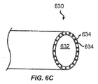
少なくとも1つの実施態様では、マニピュレータアームの遠位端と係合するように(例えば、図5を参照するツールコネクタ514に接続されるように)ハウジング626を形作ってよい。更に、ハウジング626は、マニピュレータアームの対応する要素に電気的及び/又は光学的に連結させるための電気的及び/又は光学的な要素を含んでよい。このようにして、ツール620の要素(例えば、モータ、アクチュエータ、センサ等)とマニピュレータアームの要素との間で情報を通信してよい。図6Cは、吸引ポートを備えるオーバーチューブ(overtube)の遠位端の斜視図である。オーバーチューブ630は、オーバーチューブ630を通じて延びて器具の通過を許容する器具内腔632を定める。オーバーチューブ630は、真空源に連結させられる1つ又はそれよりも多くの吸引通路634を更に含む。様々な実施態様では、外科用途に適した様々な材料のうちのいずれからもオーバーチューブ630を形成してよく、様々な剛性のうちのいずれかを備えてよい。例えば、オーバーチューブ630は、実質的に剛的な材料を含んでよく、可撓な材料を含んでよく、或いは曲げられる構造をもたらすように1つ又はそれよりも多くの実質的に剛的な部分及び1つ又はそれよりも多くの可撓な部分の組み合わせを含んでよい。オーバーチューブ630の断面形状は異なってもよい。例示の実施態様において、オーバーチューブ630は実質的に円形の断面形状を有し、ポリウレタンから作製される。他の実施態様では、用途に応じて、例えば、卵形、長方形、三角形等のような、他の断面形状を用いてよい。
In at least one embodiment, the housing 626 may be shaped to engage the distal end of the manipulator arm (eg, to be connected to the tool connector 514 with reference to FIG. 5). Further, the housing 626 may include electrical and / or optical elements for electrically and / or optically coupling to corresponding elements of the manipulator arm. In this manner, information may be communicated between elements of the tool 620 (e.g., motors, actuators, sensors, etc.) and elements of the manipulator arm. FIG. 6C is a perspective view of the distal end of the overtube with a suction port.
例示の実施態様において、吸引通路634は、オーバーチューブ630の壁内に複数の真空内腔を含み、各真空内腔は真空源(図示せず)に連結される。真空源は各吸引通路634内に真空圧を創り出し、それにより、吸引通路634が接触する組織表面上に吸引力を創り出すように動作可能であってよい。この吸引力の結果として、オーバーチューブ630は組織表面に付着させられる。真空圧が止むならば、組織表面は解放され、オーバーチューブ630はもはや組織に付着させられない。従って、吸引通路634を介して吸引力を制御可能にもたらすことによって、オーバーチューブ630を患者の組織表面に解放可能に付着させ得る。次に、器具内腔200を通じて洗浄ツール、切断ツール等のような、手術器具を挿入して、器具内腔632内に配置される組織を処置してよい。
In the illustrated embodiment, the
幾つかの実施態様では、オーバーチューブ630を実質的に剛的な材料で作製してよく、オーバーチューブ630はその位置を変更するための如何なる自由度をも含まないことがある。他の実施態様において、オーバーチューブ630は、オーバーチューブ630の遠位端の位置を変更するための自由度を加える1つ又はそれよりも多くの関節を含んでよい。例えば、オーバーチューブ630は、その遠位端のピッチ及び/又はヨーを変更するための関節を含んでよい。更に、幾つかの実施態様において、オーバーチューブ630は、その機能性を作動させるための1つ又はそれよりも多くの自由度を含んでよい。例えば、真空源(図示せず)は、1つ又はそれよりも多くの吸引通路634内の真空圧を創り出し或いは取り除くように動作可能であってよい。オーバーチューブ630並びに他の手術ツールの追加的な特徴は、同一所有者により2006年12月29日に出願された「Vacuum Stabilized Overtube for Endoscopic Surgery」という名称の米国出願第11/618,374号に記載されており、その全開示をここに参照として援用する。
In some embodiments, the
更に、少なくとも1つの実施態様では、マニピュレータアームの遠位端と係合するように形作ってよい(例えば、図5を参照するツールコネクタ514に繋がるように形作ってよい)ハウジング(図示せず)内にオーバーチューブ630を設け或いは連結してよい。更に、ハウジングは、マニピュレータアームの対応する要素に電気的及び/又は光学的に連結させるための電気的及び/又は光学的な要素を含んでよい。このようにして、オーバーチューブ630の要素(例えば、モータ、アクチュエータ、センサ等)とマニピュレータアームの要素との間で情報を通信してよい。
Additionally, in at least one embodiment, within a housing (not shown) that may be shaped to engage the distal end of the manipulator arm (eg, may be shaped to connect to the tool connector 514 with reference to FIG. 5) An
図6Dは、幾つかの実施態様ではロボット最小侵襲的手術において用いてよい、リストのない内視鏡640を例示している。リストのない内視鏡640は、図6Bを参照して描写し且つ議論したリストのある内視鏡620と類似し、よって、ハウジング646及びシャフト622を同様に含む。相違はリストのない内視鏡640が可撓なリストを含まないことである。リストのない内視鏡640は、リストのある内視鏡に比べて減少させられた数の自由度を有し、この特定の実施例において、リストのない内視鏡640はリストピッチ又はリストヨーを有さない。
FIG. 6D illustrates an
手術ツール600、内視鏡620、及びオーバーチューブ630は、様々なコンポーネントを含む様々なツールである。しかしながら、これらのツールが図6A乃至6Cに例示するよりも少ない又は多い数のコンポーネントを有することによっても等しく十分に作動し得ることが当業者によって理解されるであろう。更に、把持装置、電気外科パッドル、真空、洗浄、ステープラー(針金綴り)、鋏、ナイフ等のような、他のツールを用いてよいこと又は代替的に用いてよいことも理解されるであろう。よって、図6A乃至6C中の手術ツールの描写は本質的に例示的であり、本開示の範囲を限定しないことが理解されるべきである。
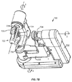
図7Aは、ある実施態様に従ったサージョンコンソール16(図1A)の一部であってよいマスタ制御入力装置700の斜視図である。マスタ制御入力装置700は、関節式連結アーム740に動作的に連結させられるジンバル又はリスト720を含む。
FIG. 7A is a perspective view of a master
マスタ制御入力装置700は、多数の自由度を有し、マニピュレータアセンブリ(例えば、図5のマニピュレータアーム)を制御するように動作可能である。入力装置700の自由度は、マニピュレータアーム500の運動学を制御するよう用いられる、入力装置700の関節によって定められる運動学的な自由度を含み、マニピュレータアーム500に接続されるツール(例えば、器具511)を作動させるよう用いられる作動自由度を含んでもよい。入力装置700は、マニピュレータアーム500のツールと同様に、それと関連付けられるエンドエフェクタ(又は、より一般的に、制御フレーム)を有するものと考えられてもよく、それ自体が多数の運動学的な自由度を有する。
Master
幾つかの実施態様において、入力装置700は、エンドエフェクタの位置を完全に制御するのに十分な数の自由度を有してよい。例えば、入力装置700は、器具511のエンドエフェクタの3つの並進及び3つの向きの自由度を独立的に制御してよい6つの自由度を有してよい。ある場合には、入力装置700がそのような十分な数の自由度を有するとしても、マニピュレータアセンブリ(例えば、マニピュレータアーム500)は、エンドエフェクタの3つの並進及び3つの向きの自由度を独立的に制御するのに不十分な数の自由度を有する。例えば、マニピュレータアーム500は、5つの自由度だけを有してよい。
In some embodiments, the
幾つかの実施態様において、入力装置700は、追加的な自由度を有してよく、追加的な自由度は、エンドエフェクタの位置を制御するよう動作可能な自由度(例えば、余剰な自由度)であってよく、且つ/或いは器具26を作動させるように動作可能な自由度(例えば、吸引又は洗浄のスイッチを入れ或いは消すこと、クランプを作動させること、ステープルを組織と係合させること等)であってよい。追加的な自由度を有する入力装置が、同一所有者による2002年4月11日に出願された「Master Having Redundant Degrees of Freedom」という名称の米国出願第10/121,283号中に記載されており、その全開示をここに参照として援用する。更に、少なくとも1つの実施態様において、器具511は、単独で或いはマニピュレータアーム500との組み合わせにおいて、マニピュレータアーム500の自由度を増大させる追加的な運動学的な自由度を有してよい。例えば、器具511は、エンドエフェクタの位置を制御する関節を有してよい。ある場合には、マニピュレータアーム500の運動学的な自由度を器具の運動学的な自由度と組み合わせるときでさえも、エンドエフェクタの位置が完全に制御されないことがある。これは、例えば、マニピュレータアーム500によって既にもたらされている運動学的な自由度にとって余剰な運動学的な自由度を加えるに過ぎない器具511の関節の故であるかもしれない。一部の実施態様において、器具511は、器具511を作動させるための追加的な作動自由度(例えば、吸引又は洗浄のスイッチを入れ或いは消すこと、クランプを作動させること、ステープルを組織と係合させること等)を有してよい。
In some embodiments,
器具511の制御を容易化するために、マスタ制御入力装置700は、1つ又はそれよりも多くのアクチュエータ又はモータを含んでよく、幾つかの実施態様では、マスタ制御入力装置700の複数の関節の各関節のためのセンサを含んでよい。例えば、サージョンコンソール16、電子機器カート24、及び/又はペイシェントカート22、及び/又はMIRSシステム10の他の要素(図1)内に配置される制御システムを介して、入力装置700のモータ及びセンサを、マニピュレータアーム500(例えば、図5のマニピュレータアーム500)と関連付けられるモータ及びセンサ並びにそれに取り付けられる手術器具(例えば、図5の器具511)に動作的に連結させてよい。制御システムは、マスタ制御装置入力とそれぞれのロボットアーム及び手術器具出力との間の制御をもたらすための、並びに、例えば、力フィードバックの場合に、ロボットアーム及び手術器具入力とそれぞれのマスタ制御出力との間の制御をもたらすための、1つ又はそれよりも多くのプロセッサを含んでよい。
To facilitate control of
図8Bは、ある実施態様に従ったジンバル又はリスト720の斜視図である。この実施態様によれば、ジンバル又はリスト720は、3つの軸、即ち、軸1、軸2、及び軸3についての作動可能なハンドル722の回転を可能にする。より具体的には、ハンドル722は、第1の旋回関節726によって第1の肘形状リンク724に連結させられる。第1のリンク724は、第2の旋回関節730によって第2の肘形状リンク728に連結させられる。第2のリンク728は、第3の旋回関節734によって第3の肘形状リンク732に旋回的に連結させられる。ジンバル又はリスト720が軸4について角度的に変位し得るように、ジンバル又はリスト720を軸4で(図7Aに示すような)関節式連結アーム740に取り付けてよい。そのようなリンク及び関節によって、ジンバル又はリスト720は、制御入力装置700のための多数の運動学的な自由度をもたらしてよく、ジンバル又はリスト720は、エンドエフェクタ自由度のうちの1つ又はそれよりも多くを制御するように動作可能であってよい。
FIG. 8B is a perspective view of a gimbal or
幾つかの実施態様において、ハンドル722は、ツール又はエンドエフェクタを作動させる一対の把持部材723(グリップ部材)を含んでよい。例えば、把持部材723を開き又は閉じることによって、エンドエフェクタ606のジョー608(図6)を同様に開き又は閉じてよい。他の実施態様において、ハンドル722の及び/又はサージョンコンソール16の他の要素の1つ又はそれよりも多くの入力要素は、器具26の位置を制御するための自由度以外の器具511の1つ又はそれよりも多くの自由度を作動させるように動作可能であってよい。例えば、サージョンコンソール16は、真空圧を作動させ且つ停止させる制御システムに連結させられるフットペダルを含んでよい。
In some embodiments, the
一部の実施態様では、例えば、力フィードバック、重力補償、及び/又は同等物をもたらすよう、ジンバル又はリスト720の関節をアクチュエータ、例えば、電気モータ又は同等物に動作的に接続してよい。更に、ジンバル又はリスト720の関節位置が制御システムによって決定されるのを可能にするために、エンコーダ、ポテンシオメータ、及び同等物のようなセンサをジンバル又はリスト720の各関節上に又はその近位に位置付けてよい。
In some embodiments, joints of the gimbal or
図7Cは、ある実施態様に従った関節式連結アーム740の斜視図である。この実施態様によれば、関節式連結アーム740は、3つの軸、即ち、軸A、軸B、及び軸Cについてのジンバル又はリスト720(図7B)の回転を可能にする。より具体的には、図7Bを参照して前述したように、ジンバル又はリスト720を軸4でアーム740に取り付けてよい。ジンバル又はリスト720は、第1のリンク742に連結させられ、第1のリンク742は、第1の旋回関節746によって第2のリンク744に旋回的に連結させられる。第2のリンク744は、第2の旋回関節750によって第3のリンク748に旋回的に連結させられる。第3の旋回関節752によって第3のリンク748をサージョンコンソール16(図1)に旋回的に連結させてよい。そのようなリンク及び関節によって、関節式連結アーム740は、制御入力装置700のための多数の運動学的な自由度をもたらしてよく、マニピュレータアセンブリの運動学的な自由度のうちの1つ又はそれよりも多くを制御し、それにより、器具(例えば、図5の器具511)の位置を制御するように動作可能であってよい。
FIG. 7C is a perspective view of an articulating
幾つかの実施態様では、例えば、力フィードバック、重力補償、及び/又は同等物をもたらすために、関節式連結アーム740の関節をアクチュエータ、例えば、電気モータ又は同等物に動作的に接続してよい。更に、関節式連結アーム740の関節位置が制御システムによって決定されるのを可能にするために、エンコーダ、ポテンシオメータ、及び同等物のようなセンサを関節式連結アーム740の各関節上に又はその近位に位置付けてよい。
In some embodiments, the joints of the articulating
入力装置700は、特定の実施態様において、外科医又は他の操作者からの入力を受信する装置であり、ジンバル又はリスト720及び関節式連結アーム740のような様々なコンポーネントを含む。しかしながら、入力装置は図7A乃至7Cに例示するよりも少ない又は多い数のコンポーネントを有することによっても等しく十分に作動し得ることが当業者によって理解されるであろう。よって、図7A乃至7C中の入力装置700の描写は本質的に例示的であり、本開示の範囲を限定しないことが理解されるべきである。
The
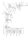
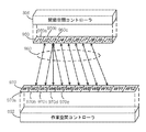
図8Aは、第1の実施態様に従ったマニピュレータアセンブリ810と支持構造850とを含むロボットシステムの一部である。マニピュレータアセンブリ810は、マニピュレータ820及びツール840を含み、その場合、マニピュレータ820は、支持構造850とツール840との間に配置され、マニピュレータ820を支持構造850及びツール840の各々に接続してよい。
FIG. 8A is a portion of a robotic system that includes a
マニピュレータ820は、関節824によって連結させられる複数のリンク822を含む。マニピュレータ820は、モータのような多数のアクチュエータ826や、ポテンシオメータのような多数のセンサ828も含んでよく、その場合には、各関節をアクチュエータ及び/又はセンサと関連付けてよい。アクチュエータは、例えば、1つ又はそれよりも多くの関節を制御して回転、並進等させることによって、マニピュレータの自由度を制御するように動作可能であってよい。更に、センサは対応する関節の各々の位置又は状態を測定するように動作可能であってよい。
マニピュレータ820は、支持構造850の対応するコネクタと係合するように形作られる近位端にあるコネクタ830も含み、コネクタ830は、マニピュレータアーム820を支持構造850に機械的に連結させるように動作可能な機械的インターフェースを形成する。コネクタ830は、電気的及び/又は光学的な接点832も含んでよく、電気的及び/又は光学的な接点832は、支持構造850の対応する接点と係合するような位置、大きさ、及び形状にされ、それにより、電気的及び/又は光学的な接点832は、マニピュレータアセンブリ810の要素と支持構造850の要素との間で情報を通信するように動作可能な電気的インターフェースを形成してよい。接点832をアクチュエータ826及び/又はセンサ828のようなマニピュレータ820の要素に直接的に又は間接的に(例えば、電気的、光学的等に)連結させてよい。1つの実施態様において、各接点832は、1つのアクチュエータ826又はセンサ828に連結させられる。従って、マニピュレータ820の要素(例えば、アクチュエータ826及びセンサ828)と支持構造850の要素との間で情報を通信してよい。例えば、支持構造からモータ826に情報を伝達して、モータにマニピュレータアーム820の対応する自由度を制御させてよく、センサ828から支持構造850の要素に位置/状態情報を伝達してよい。
The
幾つかの実施態様において、マニピュレータ820は、ツール840の対応するコネクタと係合するように形作られる遠位端にあるコネクタ834を含んでもよく、コネクタ834は、マニピュレータアーム820をツール840に機械的に連結させるように動作可能な機械的インターフェースを形成する。コネクタ834は、ツール840内に含められる対応する機械的な要素842と係合するような大きさ及び形状にされてよい。ツール840がマニピュレータ820と係合した後、機械的な要素836の作動がツール840内の対応する機械的な要素840の作動を引き起こし得るように、アクチュエータ826によって機械的な要素836を作動させ或いはその他の方法において制御してよい。ツール840内の対応する機械的な要素842は、ツール840の自由度(例えば、ツール840のエンドエフェクタ844を作動させること)を操作するように動作可能であってよい。一部の実施態様において、マニピュレータ820内に含められる又はマニピュレータ820上に配置される1つ又はそれよりも多くのセンサ828は、ツール840の位置及び/又は状態を感知するように動作可能であってよい。
In some embodiments, the
支持構造850は、マニピュレータ820の対応するコネクタ(例えば、コネクタ830)と係合するように形作られるコネクタ852を含む。コネクタ852は、マニピュレータ820の対応する接点(例えば、接点832)と係合するような位置、大きさ、及び形状にされる電気的及び/又は光学的な接点854も含み、それにより、電気的及び/又は光学的な接点854は、マニピュレータアーム820の要素とツール840の要素との間で情報を通信するように動作可能な電気的インターフェースを形成してよい。接点854を、ハードウェアマッピングユニット856、関節空間コントローラ858、関節空間作業空間マッピングユニット860、及び/又は作業空間コントローラ862のような支持構造850の要素に、直接的に又は間接的に(例えば、電気的に、光学的等に)連結させてよい。
1つの実施態様において、ハードウェアマッピングユニット856は、マニピュレータアセンブリ810(例えば、電気的/光学的な接点854を介した、例えば、マニピュレータアセンブリのアクチュエータ、センサ等への/アクチュエータ、センサ等からの信号)と関節空間コントローラ858との間の信号をマッピングするように動作可能である。ハードウェアマッピングユニット856は、異なるマニピュレータアーム820及び/又は異なるツール840のような、複数の異なるマニピュレータアセンブリの各々のために特別なマップを含んでよい(且つ/或いは取得してよい)。一部の実施態様において、ハードウェアマッピングユニット856は、入力マップ及び出力マップを含んでよい。1つの実施態様において、入力マップ及び出力マップは互いに異なってよい。例えば、アクチュエータ826及びセンサ828が、単一の接点854を介して支持構造850とそれぞれ通信してよい。従って、入力マップは、センサ828に対応する接点854からの信号を関節空間コントローラ858にマッピングしてよく、出力マップは、関節空間コントローラ858からの信号をアクチュエータ826に対応する接点854にマッピングしてよい。他の実施態様において、入力マップ及び出力マップは互いに同じであってよい。例えば、アクチュエータ826及びセンサ828が、両方とも、単一の接点854を介して支持構造850と通信してよい。従って、入力マップ及び出力マップは同じであってよい。何故ならば、それらは関節空間コントローラ858の入力及び出力要素を同じ接点854にマッピングしてよいからである。
In one embodiment, the
関節空間コントローラ858は、関節空間内で計算を行って多数のアルゴリズムを実行するように動作可能なプロセッサであってよい。例えば、関節空間コントローラ858は、関節運動アルゴリズム、各関節上の余剰なセンサの比較、モータ健康アルゴリズム等を実行するように動作可能であってよい。
The
関節空間コントローラ858は、多数の異なるセンサからの入力情報を受信してよい。例えば、関節空間コントローラ858は、関節空間作業空間マッピングユニット860を介して作業空間コントローラ862からの出力を受信してよい。他の例として、関節空間コントローラ858は、ハードウェアマッピングユニット856を介してマニピュレータ820からの入力(例えば、センサ826からのセンサ信号)を受信してよい。更に他の例として、関節空間コントローラ858は、マスタ制御入力装置(図7A乃至7C)のような入力装置からの入力を受信してよい。更に、関節空間コントローラ858は、出力情報を多数の異なる目的場所にもたらしてよい。例えば、関節空間コントローラ858は、ハードウェアマッピングユニット856を介して、情報(例えば、制御情報)をマニピュレータ820に(例えば、アクチュエータ826に)出力してよい。他の例として、関節空間コントローラ858は、更なる処理のために、関節空間作業空間マッピングユニット860を介して、作業空間コントローラ862に出力をもたらしてよい。更に他の例として、関節空間コントローラ858は、マスタ制御入力装置(図7A乃至7C)のような入力装置に出力をもたらしてよい。
The
関節空間作業空間マッピングユニット860は、関節空間コントローラ858(例えば、マニピュレータアセンブリ810の自由度の所望の又は実際の位置又は状態を表す信号)と作業空間コントローラ862との間の信号をマッピングするよう動作可能である。関節空間作業空間マッピングユニット860は、異なるマニピュレータアーム820及び/又は異なるツール840のような、複数の異なるマニピュレータアセンブリの各々のための特別なマップを含んでよい。従って、関節空間作業空間マッピングユニット860は、支持構造850に接続される特定のマニピュレータアセンブリ810に基づき、関節空間コントローラ858の入力/出力インターフェース要素を作業空間コントローラ862の入力/出力インターフェース要素にマッピングするように動作可能であってよい。
The joint space
作業空間コントローラ862は、多次元(例えば、三次元)作業空間内で計算を行って多数のアルゴリズムを実行するように動作可能なプロセッサであってよい。これは、例えば、極座標、デカルト座標、又は他の種類の座標系に基づく作業空間であってよい。作業空間コントローラ862は、様々なアルゴリズムを実行するように動作可能であってよい。例えば、作業空間コントローラ862は、順運動学、逆運動学を行い、所望の及び実際の位置/向き等の間の作業空間エラーを決定するように動作可能であってよい。
作業空間コントローラ862は、多数の異なるソース(源)から入力情報を受信してよい。例えば、作業空間コントローラ862は、関節空間作業空間マッピングユニット860を介して関節空間コントローラ858からの出力を受信してよい。他の例として、作業空間コントローラ862は、マスタ制御入力装置(図7A乃至7C)のような入力装置からの入力を受信してよい。更に、作業空間コントローラ862は、多数の異なる目的場所に出力情報をもたらしてよい。例えば、作業空間コントローラ862は、関節空間作業空間マッピングユニット860を介して関節空間コントローラ858に情報(例えば、制御情報)を出力してよい。更に他の例として、作業空間コントローラ862は、マスタ制御入力装置(図7A乃至7C)のような入力装置に出力をもたらしてよい。
少なくとも1つの実施態様では、同じ又は異なる数の自由度を有する、複数の異なるツールを設けてよい。ツールを全て同じマニピュレータアームに取り付けてよいように、ある場合には、外科処置中に交換してよいように、ツールは全て同じ機械的インターフェースを有してよい。更に、同じ又は異なる自由度を有する、複数の異なるマニピュレータアームを設けてよい。マニピュレータアームを全て同じ支持構造に並びに同じツールに取り付けてよいように、ある場合には、外科処置中に又は外科処置の間に交換してよいように、マニピュレータアームも同じ機械的インターフェースを有してよい。 In at least one embodiment, a plurality of different tools may be provided having the same or different number of degrees of freedom. The tools may all have the same mechanical interface so that they may all be attached to the same manipulator arm and, in some cases, may be exchanged during a surgical procedure. Furthermore, a plurality of different manipulator arms may be provided, having the same or different degrees of freedom. The manipulator arms also have the same mechanical interface so that they may all be attached to the same support structure as well as to the same tool, and in some cases they may be exchanged during or during a surgical procedure. You may
1つの実施態様において、ここに記載するコントローラ及び/又はマッピングユニットは、個別の又は共通の情報記憶要素に連結させられる個別のプロセッサであってよい。他の実施態様では、ここに記載するコントローラ及び/又はマッピングユニットを有形の持続性のコンピュータ読出し可能な記憶媒体として実施してよい。支持構造850の一部としてこれらの要素を記載するが、幾つかの実施態様では、これらの要素の一部又は全部を、例えば、マニピュレータ820、サージョンコンソール16、電子機器カート24、及び/又はペイシェントカート22、及び/又はMIRSシステムの任意の他の要素(図1)内に配置される制御システム内のような、ロボットシステムの他の部分に含めてよい。
In one embodiment, the controller and / or mapping unit described herein may be a separate processor coupled to a separate or common information storage element. In other embodiments, the controller and / or mapping unit described herein may be implemented as a tangible, non-transitory computer readable storage medium. While these elements are described as part of the
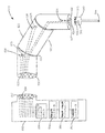
図8Bは、第2の実施態様に従ったマニピュレータアセンブリ810と、支持構造850とを含む、ロボットシステムの一部である。この実施態様におけるマニピュレータアセンブリ810及び支持構造850は、図8Aを参照して議論したものと類似しており、よって、図8Aを参照して議論した構造及び機能は、この実施態様に等しく当て嵌まる。
FIG. 8B is a portion of a robotic system that includes a
しかしながら、この実施態様によれば、ツール840は、ツール840の内部要素848と情報を通信するように連結され且つ動作可能である電気的/光学的な接点846を含む。要素848は、例えば、アクチュエータ826のようなアクチュエータ及び/又はセンサ828のようなセンサであってよい。アクチュエータは、ツール840の自由度を制御するように動作可能であってよく、センサ828は、自由度の位置及び/又は状態を感知するように動作可能であってよい。例えば、アクチュエータはツール840の関節を制御するように動作可能であってよく、センサは関節の位置を感知するように動作可能であってよい。幾つかの実施態様において、ツール840は、ツール840の多数の自由度を制御するために多数のアクチュエータ及び/又はセンサを含んでよい。少なくとも1つの実施態様において、各ツール840内の同じ電気的/光学的な接点846、即ち、接点837に連結する接点は、異なるツール内の異なる自由度を制御するように動作可能であってよい。例えば、1つの実施態様において、接点837及び846は、第1のツールのロールを制御するように動作可能であってよいに対し、接点837及び接点846は、第2のツールのピッチを制御するように動作可能であってよい。
However, according to this embodiment,
更に、マニピュレータアーム820の接点834は、ツール840とマニピュレータアーム820との間の通信を促進するために、ツール840の接点846と電気的/光学的に係合するための電気的/光学的な接点837を含んでもよい。マニピュレータアーム820のアクチュエータ826及びセンサ828と同様に、ツール840と支持構造850との間で情報を通信し得るように、接点837をマニピュレータアーム820の近位端で接点830の1つ又はそれよりも多くの接点832に連結させてよい。
Further, the
図8Cは、第3の実施態様に従ったマニピュレータアセンブリ810と、支持構造850とを含む、ロボットシステムの一部である。この実施態様におけるマニピュレータアセンブリ810及び支持構造850は、図8Aを参照して議論したものに類似しており、よって、図8Aを参照して議論した構造及び機能は、この実施態様にも等しく当て嵌まる。
FIG. 8C is a portion of a robotic system that includes a
ツール840は、この実施態様において、ツール識別ユニット845を含む。ツール識別ユニット845は、ツールの1つ又はそれよりも多くの特徴を識別するツール識別子を格納してよい。例えば、ツール識別子は、ツールの種類(例えば、内視鏡、ジョー、真空、電気外科パッドル等)、ツールの自由度の数(例えば、3つの自由度、4つの自由度、5つの自由度等)、自由度の種類(例えば、ロール、並進等のような運動自由度、真空又は電極を作動させることのような作動自由度等)等を識別してよい。ツール識別ユニット845は、ツール識別子を支持構造の要素のようなロボットシステムの他の要素に伝達するように動作可能であってよい。その場合には、ハードウェアマッピングユニット856及び/又は関節空間作業空間マッピングユニット860を構成するためのような様々な目的のために、ツール識別子を用いてよい。
様々な技法のうちの1つ又はそれよりも多くを用いてツール識別ユニット845を実施してよい。例えば、ツール識別ユニット845をツール840の接点(例えば、接点846)に連結させてよく、よって、ツール識別ユニット845は、1つ又はそれよりも多くのワイヤを介してツール識別子と通信するように動作可能であってよい。他の例として、ツール識別ユニット845は、ツール識別子と無線通信するように動作可能であってよい。例えば、ツール識別ユニット845は、ツール840の1つ又はそれよりも多くの特徴と関連付けられる識別子を有する無線ICタグ(RFID)であってよい。従って、マニピュレータアーム820は、ツール840がマニピュレータアーム820の範囲内にあるときにツール識別子を読み取るRFIDリーダ839を含んでよい。RFIDリーダ839がツール識別子を支持構造850の要素のようなロボットシステムの他の要素に通信するように動作可能であってよいように、RFIDリーダ839をコネクタ830の1つ又はそれよりも多くの接点832に連結させてよい。
他の実施態様では、ツール840からロボットシステムの他の要素にツール識別子を伝達するために、他の無線技法を用いてよい。例えば、ツール840及びロボットシステムの他の要素(例えば、マニピュレータ820、支持構造850、又は他の要素)は、Bluetooth(TM)回路構成、IEEE802.11規格に従って通信するための無線通信回路、IrDA規格、又は他の無線通信規格を含んでよい。
In other embodiments, other wireless techniques may be used to communicate tool identifiers from
更に、一部の実施態様において、マニピュレータアーム820は、マニピュレータ及び/又は接続されるツールの1つ又はそれよりも多くの特徴を識別するマニピュレータ識別子を格納してよいマニピュレータ識別ユニット(図示せず)も含んでよい或いは代替的に含んでよい。例えば、マニピュレータ識別子は、マニピュレータの種類(例えば、平行四辺形)、マニピュレータ及び/又は接続されるツールの自由度の数(例えば、3つの自由度、4つの自由度、5つの自由度等)、マニピュレータ及び/又は接続されるツールの自由度の種類(例えば、ロール、並進等のような運動自由度、真空又は電極を作動させるような作動自由度等)等を識別してよい。マニピュレータ識別ユニットは、マニピュレータ識別子を支持構造の要素のようなロボットシステムの他の要素に通信するように動作可能であってよい。その場合には、ハードウェアマッピングユニット856及び/又は関節空間作業空間マッピングユニット860を構成するためのような様々な目的のためにマニピュレータ識別子を用いてよい。ツール識別ユニット845と同様に、マニピュレータ識別ユニットは、有線手段を介して(例えば、接点832を通じて)又は無線手段を介して(例えば、マニピュレータアーム820に連結させられるRFIDタグ及び支持構造850に連結させられるRFIDリーダを介して)、マニピュレータ識別子をロボットシステムの他の要素に通信するように動作可能であってよい。
Further, in some embodiments,
マニピュレータアセンブリ810及び支持構造850は、特定の実施態様において、アクチュエータ、センサ、関節、ツール、コネクタ、マッピングユニット、及びコントローラのような、様々なコンポーネントを含む。しかしながら、入力装置が図8A乃至8Cに例示するよりも少ない又は多い数のコンポーネントを有することによっても等しく十分に作動し得ることが当業者によって理解されるであろう。更に、図8A乃至8Cの各々を参照して記載した要素を同時に又は互いに別々に用い得ることが当業者によって理解されるであろう。例えば、図8Cを参照して記載する識別システムを、図8Bを参照して記載するシステムと共に用い得る。よって、図8A乃至8Cにおけるマニピュレータアセンブリ810及び支持構造850の描写は本質的に例示的であり、本開示の範囲を限定しないことが理解されるべきである。
図9Aは、第1の実施態様に従ったコネクタ入力/出力要素と関節空間インターフェース要素との間のマッピングを例示している。コネクタ入力要素910とコネクタ出力要素920と関節空間インターフェース要素930との間の第1のマッピングとして図示のマッピングを例示している。
FIG. 9A illustrates the mapping between connector input / output elements and joint space interface elements according to the first embodiment. The illustrated mapping is illustrated as a first mapping between
コネクタ入力要素910は、幾つかの実施態様において、マニピュレータアセンブリのセンサ信号を受信する要素のような、ハードウェア装置の層の一部である。例えば、コネクタ入力要素910は、マニピュレータアセンブリ内に配置される知覚装置(例えば、センサ828)のような装置からの情報を受信するように指定される電気的及び/又は光学的な接点(例えば、接点854)に対応してよい。従って、各接点はマニピュレータアセンブリの要素からの情報を受信するように動作可能であってよい。
The
1つの実施態様において、コネクタ入力要素910のうちの1つ又はそれよりも多くは、センサ信号912を受信する。センサ信号912は、接続されるマニピュレータアセンブリの関節状態を示してよい。例えば、センサ信号912は、マニピュレータアセンブリ810の自由度の位置又は状態を測定するセンサ828から受信される情報であってよい。その自由度は、マニピュレータアーム820の自由度に対応してよく、幾つかの実施態様では、接続されるツール840の自由度に対応してよい。
In one embodiment, one or more of
図9Aに例示する実施例において、センサ信号912は、マニピュレータアームの外側ヨー(A1)の状態又は位置を示している。センサ信号914のような他のセンサ信号は、接続されるマニピュレータアセンブリの異なる関節の状態又は位置を示してよい。例えば、センサ信号914は、この実施例において、マニピュレータアームの外側ピッチ(A2)の状態又は位置を示してよい。更に他のセンサ信号は、外側ロール(A3)、挿入関節(A4)、及び器具ロール(A5)のような、接続されるマニピュレータアセンブリのより多くの関節の状態又は位置を示してよい。コネクタ入力要素910で受信されるセンサ信号によって示される特定の関節は、多くの実施態様において、マニピュレータアセンブリ810によって決定されることが認識されるべきである。即ち、コネクタ入力要素910で受信されるセンサ信号は、取り付けられるマニピュレータアセンブリ上の対応する接点(例えば、電気的及び/又は光学的な接点832)でもたらされるセンサ信号に対応してよく、その場合、マニピュレータアセンブリの接点でもたらされるセンサ信号は、異なるマニピュレータアーム及び/又はツールのための異なる関節又は自由度を示してよい。幾つかの実施態様において、マニピュレータアセンブリの異なる関節又は自由度は、マニピュレータアセンブリのツールを変更することに起因することがある。
In the example illustrated in FIG. 9A, the
次に、コネクタ入力要素910でもたらされるセンサ信号は、第1のマッピング940を介して関節空間インターフェース要素930に伝達される。例えば、ハードウェアマッピングユニット856によって第1のマッピング940を生成してよい。第1のマッピング940は、受信するセンサ信号を特定の関節空間インターフェース要素930にマッピングするように動作可能であってよい。
The sensor signal provided at
関節空間インターフェース要素930は、一定の又はその他の方法において事前設定される特徴を有する1つ又はそれよりも多くの要素を含んでよい。例えば、1つ又はそれよりも多くののマニピュレータアセンブリ(即ち、マニピュレータアーム及び/又はツール)の特定の自由度にそれぞれ対応するように関節空間インターフェース要素930を定めてよい。図9Aに例示する実施例において、関節空間インターフェース要素930は、例えば、二次的な外側ヨー(J1)、外側ヨー(J2)、外側ピッチ(J3)、外側ロール(J4)、器具ロール(J6)、及び追加的な関節(J7)乃至(J10)に対応するように予め定められる。
The joint
幾つかの実施態様において、関節空間インターフェース要素930は、プロセッサによって実行される、或いは幾つかの実施態様では、関節空間コントローラ858のようなコントローラ内に実行される、アルゴリズムの入力/出力要素として作動してよい。従って、関節空間コントローラ858は、例えば、個々の関節の上をループする1つ又はそれよりも多くのアルゴリズムを実行することによって、関節空間内でセンサ信号を処理するように動作可能であってよい。
In some embodiments, joint
次に、関節空間コントローラ858は、同じ又は異なる関節空間インターフェース要素930を介して、結果を出力するように動作可能であってよい。図9Aに例示する実施例において、関節空間コントローラ858は、同じ関節空間インターフェース要素930を用いて結果を出力する。出力信号は、例えば、アクチュエータ826のようなマニピュレータアセンブリの1つ又はそれよりも多くの要素を制御する制御信号であってよい。第2のマッピング950を介して関節空間インターフェース要素930を1つ又はそれよりも多くのコネクタ出力要素920にマッピングしてよい。例えば、ハードウェアマッピングユニット856によって第2のマッピング950を生成してよい。第2のマッピング950は、関節空間インターフェース要素930の出力をコネクタ出力要素920にマッピングするように動作可能であってよい。
The
コネクタ出力要素920は、幾つかの実施態様において、制御信号をマニピュレータアセンブリに送信する要素のような、ハードウェア装置の層の一部である。例えば、コネクタ出力要素920は、マニピュレータアセンブリ内に配置されるアクチュエータ(例えば、アクチュエータ826)のような装置に情報を送信するよう指定される電気的及び/又は光学的な接点(例えば、接点854)に対応してよい。従って、各接点は、マニピュレータアセンブリの要素に情報を伝達するように動作可能であってよい。図9Aに示す実施例では、制御信号922が、マニピュレータアセンブリ810の外側ヨーを制御するためにマニピュレータアセンブリ810のアクチュエータに出力されるのに対し、制御信号924が、マニピュレータアセンブリ810の外側ピッチを制御するためにマニピュレータアセンブリ810のアクチュエータに出力される。
幾つかの実施態様において、コネクタ入力要素910及びコネクタ出力要素920は互いに別個であるのに対し、他の実施態様において、コネクタ入力要素910及びコネクタ出力要素920は互い同じであってよい。図9Aに示す実施例において、コネクタ出力要素920はコネクタ入力要素910と異なり、センサ828からのセンサ信号を受信するために一部の接点832を用いてよいのに対し、制御信号をアクチュエータ826に送信するために他の接点832を用いてよいことを示している。しかしながら、他の実施態様では、コネクタ出力要素920はコネクタ入力要素910と同じであってよく、センサ828からセンサ信号を受信すること及びアクチュエータ826に制御信号を送信することの両方のために一部の接点832を用いてよいことを示している。
In some embodiments,
第1のマッピング940及び第2のマッピング950に戻ると、これらのマッピングはコネクタ入力/出力要素に受信される/伝達される信号を適切な関節空間インターフェース要素に/からマッピングするように動作することが明らかであるはずである。多くの実施態様において、これらのマッピングは異なるマニピュレータアセンブリについて異なる。例えば、図9Aに例示する実施態様において、第1のコネクタ入力要素910aは、マニピュレータアセンブリから如何なる信号をも受信しないのに対し、第2のコネクタ入力要素920bは、マニピュレータアセンブリの外側偏角の位置又は状態を示すセンサ信号を受信してよい。次に、第1のマッピング940は、その特定のマニピュレータアセンブリに合わせてカスタマイズされ、第2のコネクタ入力要素910bを第2の関節空間(例えば、関節空間インターフェース要素930)インターフェース要素930bにマッピングするように作動し、関節空間コントローラ858は、第2の関節空間インターフェース要素930bを取り、外側ヨー自由度として処理する。第1のマッピング940は、如何なる信号をも第1の関節空間インターフェース要素930aにマッピングしない。何故ならば、マニピュレータアセンブリは、第2の外側ヨー地点に対応する如何なる自由度をも有さないからである。
Returning to the
図9Bを一時的に参照すると、図9Bは、第2の実施態様に従ったコネクタ入力/出力要素と関節空間インターフェース要素との間のマッピングを例示している。この実施態様は、この場合には、センサ信号912が第2のコネクタ入力要素910bで受信されず、むしろ第3のコネクタ入力要素910cで受信されるように、支持構造850が異なるマニピュレータアセンブリ820に連結させられている(マニピュレータアセンブリはアセンブリのツールの交換の結果として異なり得る)点を除き、図9Aを参照して議論したものに類似している。関節空間インターフェース要素930は異なるマニピュレータアセンブリと交換しないので、コネクタ入力要素910で受信されるセンサ信号が適切な関節空間インターフェース要素930にマッピングされるように、第1のマッピング940が変わらなければならない。図9Bの実施例において、新しいマニピュレータアセンブリに対応する第1のマッピング941は、第3のコネクタ入力要素910cを、図9Aの実施例において行ったように第3の関節空間インターフェース要素930cにマッピングするのではなく、第2の関節空間インターフェース要素930bにマッピングする。同様に、図9B中の実施例は、図9A中の実施例において用いたものと異なる第2のマッピング951を用いてよい。異なるマニピュレータアセンブリのために異なるマッピングを用いることによって、有利なことには、異なるマニピュレータアセンブリのために同じ関節空間コントローラ858を用いてよい。
Referring temporarily to FIG. 9B, FIG. 9B illustrates the mapping between connector input / output elements and joint space interface elements according to the second embodiment. In this embodiment, the
図9Cは、ある実施態様に従った関節空間インターフェース要素と作業空間インターフェース要素との間のマッピングを例示している。関節空間インターフェース要素960は、この実施態様において、関節空間作業空間マッピング980を介して作業空間インターフェース要素970にマッピングされる。関節空間インターフェース要素960は、図9A及び9Bを参照して議論したものと類似してよいが、この実施態様では、関節空間コントローラ858と作業空間コントローラ862との間で情報を通信するように動作可能であってよい。
FIG. 9C illustrates the mapping between the joint space interface element and the work space interface element according to an embodiment. The joint
幾つかの実施態様において、作業空間インターフェース要素970は、プロセッサによって実行される、或いは幾つかの実施態様では、作業空間コントローラ862のようなコントローラ内に実行される、アルゴリズムの入力/出力要素として作動してよい。従って、作業空間コントローラ862は、作業空間インターフェース要素970を介して作業空間内で関節空間コントローラ858によって出力される信号を受信することによって、それらの信号を処理するように動作可能であってよい。少なくとも1つの実施態様において、作業空間コントローラ862は、機械的リンク装置又は作業空間自由度の層に対応する。例えば、作業空間インターフェース要素970の各々は、マニピュレータアセンブリの特定のリンク装置に対応してよい。作業空間コントローラ862は、任意の適切な数の次元(例えば、一次元、二次元、三次元、三次元よりも大きい次元等)において、デカルト座標系、極座標系等のような、1つ又はそれよりも多くの座標系内で、関節空間コントローラ858からの出力に対する計算を行うように動作可能であってよい。作業空間コントローラが行う計算は、例えば、順運動学、逆運動学、及び他のデカルト空間(cart-space)及び零空間(null-space)を含んでよい。
In some embodiments,
関節空間作業空間マッピング980は、図9A及び9Bを参照して議論したものと同様に、異なるマニピュレータアセンブリのために異なってよい。関節空間作業空間マッピング980は、関節空間インターフェース要素960作業空間インターフェース要素970にマッピングするように動作する。例えば、関節空間作業空間マッピング980は、関節空間コントローラ858からの出力信号を適切な作業空間インターフェース要素970にマッピングしてよく、同様に、作業空間インターフェース要素970からの出力信号を適切な関節空間インターフェース要素960にマッピングしてよい。幾つかの実施態様では、例えば、関節空間作業空間マッピングユニット860によって、関節空間作業空間マッピング980を作成してよい。
The joint space
幾つかの実施態様では、関節空間インターフェース要素を作業空間インターフェース要素に全くマッピングしないことがあり、その結果、固定的なフレーム変換がもたらされる。例えば、第1の関節空間インターフェース要素960aは、如何なる作業空間インターフェース要素970にもマッピングされず、第1の作業空間インターフェース要素970aは、如何なる関節空間インターフェース要素960にもマッピングされない。これが当て嵌まることがあるのは、取り付けられるマニピュレータアセンブリが第1の関節空間インターフェース要素960aの自由度に対応する自由度(例えば、第2の外側ヨー地点)を有さない場合である。
In some implementations, no joint space interface elements may be mapped to workspace interface elements, resulting in a fixed frame transformation. For example, the first joint space interface element 960a is not mapped to any work
少なくとも1つの実施態様では、単一の関節空間インターフェース要素を単一の作業空間インターフェース要素にマッピングしてよい。例えば、第2の関節空間インターフェース要素960bを第2の作業空間インターフェース要素970bにマッピングしてよい。これが当て嵌まることがあるのは、取り付けられるマニピュレータアセンブリが第2の関節空間インターフェース要素960bの自由度に対応する自由度(例えば、外側ヨー自由度)を有する場合であり、その自由度は、単一のリンクの動きに対応する。
In at least one embodiment, a single joint space interface element may be mapped to a single work space interface element. For example, the second joint
少なくとも1つの実施態様では、単一の関節空間インターフェース要素を多数の作業空間インターフェース要素にマッピングしてよい。例えば、第3の関節空間インターフェース要素960cを、第3の作業空間インターフェース要素970c、第4の作業空間インターフェース要素970d、及び第5の作業空間インターフェース要素970eにマッピングしてよい。これが当て嵌まることがあるのは、マニピュレータの一部が並列機構(parallel mechanism)である場合である。並列機構は、単一の独立した自由度に基づき多数の物理的関節が同時に移動する場合である。物理的関節の1つを独立して制御し得るのに対し、他の物理的関節の運動は独立して制御される関節の動きに依存する。並列機構の実施例は、(ツール先端を単一の軸に沿って旋回させる代わりに曲線の周りに移動させる)スネークツール(snake tool)、平行四辺形軸等を含む。
In at least one embodiment, a single joint space interface element may be mapped to multiple work space interface elements. For example, the third joint space interface element 960c may be mapped to the third work
図10は、ある実施態様に従ったコネクタ入力/出力要素と関節空間インターフェース要素と作業空間インターフェース要素との間のマッピングを例示している。様々な装置、インターフェース要素、信号、及びマッピングは、図9A及び9Cを参照して議論したものと類似しているが、この場合には、マニピュレータアセンブリに通信される並びにマニピュレータアセンブリから通信される信号を作業空間コントローラによって最終的に処理される信号にマッピングする単一の相互接続されるシステムとして示されている。 FIG. 10 illustrates the mapping between connector input / output elements, joint space interface elements and work space interface elements according to an embodiment. The various devices, interface elements, signals and mappings are similar to those discussed with reference to FIGS. 9A and 9C, but in this case the signals communicated to and from the manipulator assembly Is illustrated as a single interconnected system that maps to the signal ultimately processed by the workspace controller.
少なくとも1つの実施態様では、マニピュレータセンブリの自由度を制御するために受信され且つ伝達される実際の信号を処理することに加えて、システムは、擬態(simulated)又は仮想(phantom)自由度のための処理を行うように動作可能であってもよい。例えば、幾つかの実施態様において、マニピュレータアセンブリは、1つ又はそれよりも多くの自由度を欠いていてよく、例えば、それはロールするように動作可能でなくてよい。しかしながら、関節空間コントローラ858及び/又は作業空間コントローラ862のようなコントローラによって実行される計算を、そのような自由度がマニピュレータアセンブリに実際に存在するという推定に基づき行ってよい。
In at least one embodiment, in addition to processing the actual signals received and transmitted to control the degree of freedom of the manipulator assembly, the system is for simulated or phantom degrees of freedom. May be operable to perform the processing of For example, in some embodiments, the manipulator assembly may lack one or more degrees of freedom, eg, it may not be operable to roll. However, calculations performed by controllers such as
例えば、関節空間コントローラ858は、マニピュレータアセンブリの特定のロール及びピッチのような自由度に対応してよい関節空間インターフェース要素930a及び930hで入力信号を受信せず、関節空間コントローラ858は、関節空間インターフェース要素930a及び930hで出力をもたらさないが、関節空間コントローラ858は、それにも拘わらず、関節空間インターフェース要素930g及び930hに対応する自由度が制御されると仮定してアルゴリズムを実行してよい。
For example,
従って、幾つかの実施態様において、関節空間作業空間マッピング980は、これらの仮想の自由度と関連付けられる信号を処理するマッピングを含んでよい。例えば、関節空間作業空間マッピング980は、例えば、仮想のピッチに対応する、関節空間インターフェース要素930gを、作業空間インターフェース要素970iにマッピングしてよく、例えば、仮想のヨーに対応する、関節空間インターフェース要素930hを、作業空間インターフェース要素970jにマッピングしてよい。次に、作業空間コントローラ862も、作業空間インターフェース要素970i及び970jに対応するリンクが存在し且つ制御されると仮定して、関節空間コントローラ858と同様に計算を行ってよいが、実際には、それらは制御されず、接続されるマニピュレータアセンブリ上に存在しないことさえある。
Thus, in some embodiments, joint
コネクタ入力要素910、コネクタ出力要素920、関節空間インターフェース要素930、及び作業空間インターフェース要素970の数は、複数のマニピュレータアセンブリを制御するのに適した如何なる数であってもよい。1つの実施態様において、関節空間インターフェース要素の数は、コネクタ(入力/出力)要素の数よりも大きい。そのような構成は、制御されることがある多数の異なる自由度を有する多数の異なるマニピュレータアセンブリが全て同じ関節空間コントローラによって制御されることを有利に可能にする。関節空間インターフェース要素の数がコネクタ要素の数よりも大きい場合には、コネクタ要素を関節空間インターフェース要素のサブセット(部分集合)にマッピングしてよい。更に、異なるマニピュレータアセンブリが同じ数の自由度を有するが、少なくとも1つの異なる自由度を有する(例えば、1つのマニピュレータが外側ピッチ自由度を含むのに対し、他のマニピュレータは外側ピッチ自由度を含まず、追加的なツール自由度を含む)場合には、マニピュレータの各々のためのコネクタ要素を関節空間インターフェース要素の異なるサブセットにマッピングしてよい。他の実施態様では、異なるマニピュレータアセンブリによって用いられるコネクタ要素の数が異なってもよい。
The number of
幾つかの実施態様において、作業空間インターフェース要素の数は、関節空間インターフェース要素の数よりも大きい。そのような構成は、1つの関節空間インターフェース要素が1つよりも多くのデカルト空間インターフェース要素にマッピングされるのを有利に可能にし、それにより、所与のマニピュレータアセンブリ自由度のための様々な機械的リンク装置の制御を容易化することがある。 In some embodiments, the number of work space interface elements is greater than the number of joint space interface elements. Such an arrangement advantageously enables one joint space interface element to be mapped to more than one Cartesian space interface element, whereby various machines for a given manipulator assembly degree of freedom Control of dynamic link devices may be facilitated.
図11A及び11Bを一時的に参照すると、図11Aは、関節空間インターフェース要素930によって制御される第1のマニピュレータアセンブリの自由度の第1の組のグループ分け1100を示しており、図11Bは、関節空間インターフェース要素930によって制御される第2のマニピュレータアセンブリの自由度の第2の組のグループ分け1150を示している。ここでは、第2のマニピュレータアセンブリは第1のマニピュレータアセンブリと異なり、よって、グループ分けは異なってよい。
Referring temporarily to FIGS. 11A and 11B, FIG. 11A shows a first set of degrees of
幾つかの実施態様において、例えば、関節空間コントローラによって実行されるアルゴリズムは、利用可能な入力のサブセットのみに対して働いてよい。例えば、関節空間コントローラ858によって実行されるアルゴリズムは、インターフェース要素930のサブセットのみに対して働いてよい(例えば、サブセットから入力を取得し、処理し、サブセットに出力を送信してよい)。異なる組の入力を受信し且つ作動しながら、異なるアルゴリズムを互いに同時に実行してよい。異なるマニピュレータ(そして、幾つかの実施態様では、異なるツール)が支持構造の同じコネクタに引き続き接続される(即ち、1つのマニピュレータが他のマニピュレータと取り替えられる(スワップされる))状況では、インターフェース要素930によって制御されるマニピュレータの関節は変化することがある。結果的に、アルゴリズムがその上で働く特定のインターフェース要素930も同様に変化することがある。
In some embodiments, for example, an algorithm executed by the joint space controller may operate on only a subset of available inputs. For example, an algorithm executed by
これらの変化を考慮に入れるために、異なる関節グループ分けを用いてよく、その場合、関節グループ分けは、特定の関節グループ分けを定める。例えば、各々が特定のインターフェースグループ分けを例示する図11A及び11Bを参照すると、インターフェース要素930b乃至930eは、第1のマニピュレータ(図11A)の外側関節に対応してよいのに対し、インターフェース要素930a乃至930eは、第2のマニピュレータ(図11B)の外側関節に対応してよい。1つ又はそれよりも多くのアルゴリズムがマニピュレータの外側関節に対してのみ働くように構成されるとき、第1のマニピュレータ(図11A)が接続されるときに、アルゴリズムはそのマニピュレータのための関節グループ分け定義を読み取って、インターフェース要素930b乃至930eを用いて外側関節が完全に定められることを決定してよい。よって、アルゴリズムはそれらのインターフェース要素に対してのみ働いてよい。例えば、第1のアルゴリズムがインターフェース要素930b乃至930eの「外側」グループを用いて働いてよく、第2のアルゴリズムがインターフェース要素930f乃至930iの「ツール」グループを用いて(同時に又は順次的に)働いてよい。対照的に、第2のマニピュレータ(図11B)が接続されるとき、アルゴリズムはそのマニピュレータのための関節定義を読み取って、インターフェース要素930a乃至930eを用いて外側関節が完全に定められることを決定してよい。よって、アルゴリズムはそれらのインターフェース要素に対して働いてよい(即ち、インターフェース要素930aを含む)。例えば、第3のアルゴリズムがインターフェース要素930a乃至930eの「外側」グループを用いて働いてよく、第4のアルゴリズムがインターフェース要素930f乃至930iの「ツール」グループを用いて働いてよい。第1、第2、第3、及び第4のアルゴリズムの各々は互いに異なってよく、インターフェース要素の特定のグループ実行するよう第1、第2、第3、及び第4のアルゴリズムの各々を最適化してよい。例えば、マニピュレータアセンブリの外側関節と関連付する入力要素のグループを実行し得るよう1つのアルゴリズムを最適化してよいのに対し、ツールの自由度に関連する入力要素のグループを実行するよう他のアルゴリズムを最適化してよい。
Different joint groupings may be used to account for these changes, in which case joint groupings define specific joint groupings. For example, referring to FIGS. 11A and 11B, each illustrating a particular interface grouping,
関節グループ分け定義は、特定のマニピュレータのためのコントローラ内のアルゴリズムによって用いられる関節グループ分けの全てを定めてよい。例えば、図11Aを参照すると、関節グループ分け定義は、図11Aに描写するような第1のマニピュレータのための「関節」、「ツール」、「ジョー」等のためのグループ分けを定めてよい。図11Bを参照すると、異なる関節グループ分け定義が、図11Bを参照に描写するような第2のマニピュレータのための「関節」、「ツール」、「ジョー」等のための(ある場合には、異なる)グループ分けを定めてよい。異なるマニピュレータのための関節グループ分け定義を(例えば、支持構造850内の)コントローラに格納してよく、或いはマニピュレータが使用のために接続される時に又は前に適切なソースから(例えば、マニピュレータ、遠隔記憶装置等から)取得してよい。 The joint grouping definition may define all of the joint groupings used by the algorithm in the controller for a particular manipulator. For example, referring to FIG. 11A, the joint grouping definition may define groupings for “joints”, “tools”, “jaws”, etc. for the first manipulator as depicted in FIG. 11A. Referring to FIG. 11B, different joint grouping definitions may be used (in some cases for “joints”, “tools”, “jaws” etc.) for the second manipulator as depicted in FIG. 11B. Different groupings may be defined. Joint grouping definitions for different manipulators may be stored in the controller (e.g., in the support structure 850) or from an appropriate source (e.g., manipulator, remote) when or before the manipulators are connected for use May be obtained from a storage device or the like.
図11A及び11Bに描写する特定の実施態様において、図11Aに例示するグループ分けのうちの少なくとも一部は、図11Bを参照に例示するものと同じである。何故ならば、図11Aのインターフェース要素によって制御されるマニピュレータアセンブリは、図11Bのインターフェース要素によって制御されるマニピュレータアセンブリの自由度と同じ自由度の少なくとも一部を有するからである。例えば、両方の組のグループ分けは、8つの関節空間インターフェース要素930h及び9つの関節空間インターフェース要素930iを、ツールのジョーを制御するように動作する関節空間インターフェース要素を示す「ジョー」グループにグループ分けする。更に、両方の組のグループ分けは、6つの関節空間インターフェース要素930f、7つの関節空間インターフェース要素930g、及び8つの関節空間インターフェース要素930hを、ツールのリストを制御するように動作する関節空間インターフェース要素を示す「リスト」グループにグループ分けする。
In the particular embodiment depicted in FIGS. 11A and 11B, at least some of the groupings illustrated in FIG. 11A are the same as those illustrated with reference to FIG. 11B. Because the manipulator assembly controlled by the interface element of FIG. 11A has at least a part of the same degree of freedom as the manipulator assembly controlled by the interface element of FIG. 11B. For example, both sets of groupings group eight joint
更に、図11Aに例示するグループ分けのうちの少なくとも一部は、図11Bに例示するものと異なる。何故ならば、図11Aのインターフェース要素によって制御されるマニピュレータアセンブリは、二次的な外側ヨー関節を含まないのに対し、図11Bのインターフェース要素によって制御されるマニピュレータアセンブリは、二次的な外側ヨー関節を含むからである。従って、マニピュレータアームを制御するように動作する関節空間インターフェース要素を識別する「外側」と定義されるグループ分けが、第1の組のグループ分け1100のために定められ、第2、第3、第4、及び第5の関節空間インターフェース要素930b乃至930eを含む。対照的に、「外側」と定義されるグループは、第2の組のグループ分け1100のために定められ、第1、第2、第3、第4、及び第5の関節空間インターフェース要素930a乃至930eを含む。何故ならば、二次的な外側偏角関節は、接続されるツールではなくマニピュレータアームの自由度に対応するからである。
Furthermore, at least some of the groupings illustrated in FIG. 11A differ from those illustrated in FIG. 11B. Because the manipulator assembly controlled by the interface element of FIG. 11A does not include a secondary outer yaw joint, the manipulator assembly controlled by the interface element of FIG. 11B is a secondary outer yaw It is because it contains a joint. Thus, a grouping, defined as "outside", identifying joint space interface elements operative to control the manipulator arm is defined for the first set of
既述のように、関節空間コントローラによって実行されるアルゴリズムは、アルゴリズムのために受信される入力データに基づき関節空間インターフェース要素930から使用する信号を選択してよい。例えば、センサ、アクチュエータ、及び/又は作業空間コントローラからの入力データは、どの関節空間インターフェース要素が、例えば、ツール自由度に対応するかをアルゴリズムに示してよく、よって、関節空間コントローラは、適切な関節空間インターフェース要素から受信される信号を用い(且つ処理された信号を適切な関節空間インターフェース要素に伝達し)てよい。他の実施態様では、関節空間インターフェース要素とマニピュレータアセンブリの自由度との間の所定の対応に基づき信号を選択してよい。例えば、特定のマニピュレータアセンブリを接続した後に、その特定のマニピュレータアセンブリに対応する、異なる関節空間インターフェース要素のグループ分けを示すグループ分け情報をロードしてよい。よって、関節空間コントローラは、特定のグループ分けによって定義される適切な関節空間インターフェース要素から受信される信号を使用し(且つ処理された信号を特定のグループ分けによって定義される適切な関節空間インターフェース要素に伝達し)てよい。
As mentioned, the algorithm executed by the joint space controller may select the signal to use from the joint
図12A及び12Bを今や参照すると、図12Aは、ある実施態様に従ったコネクタ/関節空間マップ1200を示しているのに対し、図12Bは、ある実施態様に従った関節空間/作業空間マップ1250を示している。支持構造850内の記憶要素のような、ロボットシステムの任意の適切な要素内に、それらのマップを格納してよい。コネクタ/関節空間マップ1200は、コネクタ要素1210(例えば、接点854)を関節空間インターフェース要素1220(例えば、関節空間インターフェース要素930)にマッピング(例えば、第1のマッピング940及び/又は第2のマッピング950)するマップである。コネクタ/関節空間マップ1200は、A1乃至Ai(ここで、iは任意の整数である)のような、任意の適切な数のコネクタ要素と、J1乃至Jk(ここで、kは任意の整数である)のような、関節空間インターフェース要素とを含んでよい。マッピングインジケータ1230は、特定のコネクタ要素と特定の関節空間インターフェース要素との間の特定のマッピングを示してよい。例えば、図9Aを参照すると、コネクタ要素「A2」は、第2のコネクタ入力要素910bに対応してよく、関節空間インターフェース要素「J2」は、第2の関節空間インターフェース要素960bに対応してよい。従って、マッピングインジケータ1230は、第2のコネクタ入力要素910bと第2の関節空間インターフェース要素960bとの間の信号をマッピングするように動作可能であってよい。
Referring now to FIGS. 12A and 12B, FIG. 12A shows a connector /
関節空間/作業空間マップ1250は、関節空間インターフェース要素1260(例えば、関節空間インターフェース要素930)を作業空間インターフェース要素1220(例えば、作業空間インターフェース要素970)にマッピング(例えば、関節空間作業空間マッピング980)するマップである。関節空間/作業空間マップ1250は、J1乃至Jk(ここで、kは任意の整数である)のような、任意の適切な数の関節空間要素と、W1乃至Wm(ここで、mは任意の整数である)のような、任意の数の作業空間インターフェース要素とを含んでよい。マッピングインジケータ1280が、特定の関節空間要素と特定の作業空間インターフェース要素との間の特定のマッピングを示してよい。例えば、図9Cを参照すると、関節空間インターフェース要素「J2」は、第2の関節空間インターフェース要素960bに対応してよく、作業空間インターフェース要素「W1」は、第2の作業空間インターフェース要素970bに対応してよい。従って、マッピングインジケータ1280は、第2の関節空間インターフェース要素960bと第2の作業空間インターフェース要素970bとの間の信号をマッピングするように動作可能であってよい。
The joint space / work space map 1250 maps the joint space interface element 1260 (eg, joint space interface element 930) to the work space interface element 1220 (eg, work space interface element 970) (eg, joint space work space mapping 980). Map. The joint space / work space map 1250 includes any suitable number of joint space elements, such as J1 through Jk (where k is any integer), and W1 through Wm (where m is any) And any number of workspace interface elements, such as integers). A
更に、それらのマップは1つの要素を1つよりも多くの要素にマッピングするように動作可能であってよい。例えば、再び図9Cを参照すると、関節空間インターフェース要素「J3」は、第3の関節空間インターフェース要素960cに対応してよく、作業空間インターフェース要素「W2」、「W3」、及び「W4」は、第2、第3、及び第4の作業空間インターフェース要素970c乃至970eにそれぞれ対応してよい。よって、第1、第2、及び第3のマッピングインジケータ1282,1284,1286が、第3の関節空間インターフェース要素と、第2、第3、及び第4の作業空間インターフェース要素970c乃至970eの各々との間の信号をマッピングするように動作可能であってよい。
Further, the maps may be operable to map one element to more than one element. For example, referring again to FIG. 9C, the joint space interface element "J3" may correspond to the third joint space interface element 960c, and the work space interface elements "W2", "W3", and "W4" The second, third, and fourth
支持構造は、特定の実施態様において、コネクタ要素、インターフェース要素、マッピング、関節空間コントローラ、作業空間コントローラ等のような、様々なインターフェース要素及びコントローラを含む。しかしながら、入力装置が図9A乃至12Bに例示するよりも少ない又は多い数のコンポーネントを有することによっても等しく十分に作動し得ることが当業者によって理解されるであろう。図9A乃至12Bの各々を参照して記載した要素が特定のマッピング及びこれらの実施態様を参照して例示し且つ議論した特定の自由度を必要としないことが当業者によって更に理解されるであろう。例えば、一部の自由度は、接続されるマニピュレータアームの動きに対応してよいのに対し、他の自由度は、接続されるツールの動きに対応してよく、更に他の自由度は、ツール又はマニピュレータアームの作動に対応してよい。よって、図9A乃至12B中の様々な要素の描写は本質的に例示的であり、本開示の範囲を限定しないことが理解されるべきである。 The support structure, in particular embodiments, includes various interface elements and controllers, such as connector elements, interface elements, mappings, joint space controllers, workspace controllers, and the like. However, it will be appreciated by those skilled in the art that the input device may operate equally well with fewer or more components than illustrated in FIGS. 9A-12B. It will be further understood by those skilled in the art that the elements described with reference to each of FIGS. 9A-12B do not require the particular mappings and particular degrees of freedom illustrated and discussed with reference to these embodiments. I will. For example, some degrees of freedom may correspond to movements of connected manipulator arms, while other degrees of freedom may correspond to movements of connected tools, and still other degrees of freedom It may correspond to the actuation of the tool or the manipulator arm. Thus, it should be understood that the depiction of the various elements in FIGS. 9A-12B are exemplary in nature and do not limit the scope of the present disclosure.
図13Aは、図4を参照して描写し且つ議論したペイシェントカートに類似するペイシェントカート1300を示している。しかしながら、この実施態様において、マニピュレータアームは個々に識別され、第1のマニピュレータアーム100A、第2のマニピュレータアーム100B、第3のマニピュレータアーム100C、及び第4のマニピュレータアーム100Dを含む。第1のマニピュレータアーム100Aは、イメージングデバイス28に連結させられるのに対し、第2、第3、及び第4のマニピュレータアーム(100B,100C,100D)は、各々、それぞれの手術ツール26に連結させられる。
FIG. 13A shows a
図13Bは、ペイシェントカート1300に類似するペイシェントカート1350を示している。しかしながら、この実施態様において、第1のマニピュレータアーム100Aは、手術ツール26に連結させられるのに対し、第2のマニピュレータアーム100Bは、イメージングデバイス28に連結させられる。即ち、イメージングデバイスは手術ツールのうちの1つと取り替えられる。
FIG. 13B shows a
多くの実施態様では、ペイシェントカート1350又はMIRSシステム10(図1)の他の要素を実行するソフトウェアをオフにしたりその他の方法において再起動させたりせずに、患者に対する医療処置中を含む任意の適切な時に、イメージングデバイス28を手術ツール26と取り替え得る。イメージングデバイス28を手術ツール26と取り替えることは、イメージングデバイスの視野を変更するのを容易化することがあり、取り替えられる手術ツールに利用可能な、アクセス可能な作業空間内の変化を促進することがある。
In many embodiments, any during the medical procedure for the patient may be performed without turning off or otherwise restarting the software that performs
少なくとも1つの実施態様では、手術ツール先端の基準座標系(frame of reference)が、1つのマニピュレータから他のマニピュレータにイメージングデバイス28(例えば、カメラ)を移動させる結果として変更される。例えば、手術を執り行うときには、カメラ先端に対する手術ツール先端の基準座標系が、外科医が見る画像ディスプレイに対して手術ツールを制御するために外科医が用いる入力装置の基準座標系と整合するように、空間内の物を再配置することが概ね望ましい。手術ツールが第1のマニピュレータアームに連結させられ、イメージングデバイスが第2のマニピュレータアームに連結させられるとき、外科医は(例えば、入力装置を介して)、第1のマニピュレータを介して手術ツールを駆動させる。よって、イメージングデバイス座標系(imaging device frame)に対する手術ツール先端座標系(surgical tool tip frame)は、遠隔手術のために用いられる。しかしながら、手術ツール及びイメージングデバイスは互いに取り替えられ、外科医は最後にはイメージングデバイスを駆動させることになる。結果的に、システム(例えば、関節空間コントローラ及び/又は作業空間コントローラによって実行される1つ又はそれよりも多くのアルゴリズム)は、世界座標系(world frame)に対するイメージングデバイス座標系が遠隔手術のために用いられるように、無作為な基準座標系(即ち、世界座標系)を定める。 In at least one embodiment, the frame of reference of the surgical tool tip is altered as a result of moving the imaging device 28 (eg, a camera) from one manipulator to another. For example, when performing a procedure, the spatial coordinate system of the surgical tool tip relative to the camera tip is aligned with the reference coordinate system of the input device used by the surgeon to control the surgical tool relative to the image display seen by the surgeon. It is generally desirable to rearrange things within. When the surgical tool is coupled to the first manipulator arm and the imaging device is coupled to the second manipulator arm, the surgeon (eg, via the input device) drives the surgical tool through the first manipulator Let Thus, a surgical tool tip frame to an imaging device frame is used for telesurgery. However, the surgical tool and the imaging device are replaced with each other and the surgeon will eventually drive the imaging device. As a result, the system (e.g., one or more algorithms executed by the joint space controller and / or the work space controller) may cause the imaging device coordinate system relative to the world frame to be teleoperated. Define a random reference coordinate system (ie world coordinate system) as used in
当業者は、ここに開示する様々な技法を用いてイメージングデバイス及び手術ツールの交換を容易化するのを助け得ることを認識するであろう。例えば、第1のマニピュレータアーム100A及び第2のマニピュレータアーム100Bは、マニピュレータ820(図8A乃至8C)にそれぞれ類似してよく、イメージングデバイス28及び手術ツール26の各々は、ツール840に類似してよい。従って、第1のマニピュレータアーム100A及び第2のマニピュレータアーム100Bの各々は、イメージングデバイス28及び手術ツール26の対応するコネクタと係合するに形作られるコネクタ(例えば、コネクタ834)を含んでよい。
One of ordinary skill in the art will recognize that the various techniques disclosed herein may be used to facilitate the exchange of imaging devices and surgical tools. For example,
イメージングデバイス及び手術ツールのホットスワッピング(hot-swapping)を促進するよう、例えば支持構造850が行ってよい様々な処理を、図14乃至16Bを参照して更に記載する。当業者は、実施態様がイメージングデバイスを手術ツールと取り替える(スワッピングする)ことに限定されず、手術ツールを他の手術ツールと取り替える(スワッピングする)こと、イメージングデバイスを他の種類のイメージングデバイスと取り替える(スワッピングする)こと等を含むことを認識するであろう。
Various processes that, for example,
図14は、同じマニピュレータアームに接続される多数の可能なツールからの1つを制御するために用いてよい、或いは、より一般的に、マニピュレータアセンブリがマニピュレータアーム及びツールの両方を含む場合、多数の異なるマニピュレータアセンブリを制御するために用いてよい、一連の操作を示している。支持構造850(図8A乃至8C)を参照してここに記載したコントローラのいずれかのような、任意の適切なコントローラによって、それらの操作を行ってよい。
FIG. 14 may be used to control one of many possible tools connected to the same manipulator arm, or more generally, if the manipulator assembly includes both a manipulator arm and a
操作1410において、ツールがマニピュレータに接続されているか否かを決定する。例えば、関節空間コントローラ858(又は異なるコントローラ)は、ツール840がマニピュレータアーム820に接続されているか否かを決定してよい。ツールがマニピュレータアームに接続されていないことが決定されるとき、システムはマニピュレータアームを監視し続けて、ツールが接続されているか否かを決定する。さもなければ、処理は操作1420に進んでよい。
In operation 1410, it is determined whether the tool is connected to the manipulator. For example, the joint space controller 858 (or a different controller) may determine whether the
操作1420では、接続されるツールのためのマッピングを取得する。マッピングは、図8A乃至12Bを参照して記載したマッピングのような、1つ又はそれよりも多くのマッピングを含んでよい。例えば、マッピングは、コネクタ/関節空間マップ1200(図12A)、関節空間/作業空間マップ1250(図12B)、又は接続されるツールに関連する任意の他の適切なマップを含んでよい。図15を参照してその一部を記載する多数の技法のうちの任意の1つ又はそれよりも多くを用いて、マッピングを取得してよい。
At
ツールのためのマッピングを取得するや否や、処理は操作1430に進む。操作1430では、取得したマッピングを用いて、接続されるツールを制御する。例えば、コネクタ/関節空間マップ及び関節空間/作業空間マップを用いて、関節空間コントローラ858及び作業空間コントローラ862を用いて、ツールを制御してよい。図8A乃至12Bを参照して、1つ又はそれよりも多くのマップを用いてツールを制御する様々な技法を記載する。これらの技法のうちの任意の1つ又はそれよりも多くが、接続されるツールを制御するために適用可能である。図16A及び16Bを参照して、接続されるツールを制御する更なる技法を記載する。
Upon obtaining the mapping for the tool, processing proceeds to
操作1440では、ツールがマニピュレータから取り外されたか否かを決定する。例えば、コントローラは、ツール840がマニピュレータアーム820から取り外されたか否かを決定する。ツールがマニピュレータアームから取り外されていないことが決定されるならば、取得したマッピングを用いてツールを制御し続けてよい。さもなければ、処理は操作1450に進む。
操作1450では、新しいツールがマニピュレータに接続されているか否かを決定する。この操作は操作1410に類似する。新しいツールが接続されていることが決定されるならば、操作1420において新しいツールのためのマッピングを取得してよく、操作1430において新しいマッピングを用いて新しいツールを制御してよい。さもなければ、システムは新しいツールの接続を監視し続けてよい。
At
マッピングの結果、同じマニピュレータアームに接続される異なるツールを制御するプロセッサ(例えば、関節空間コントローラ858及び/又は作業空間コントローラ862)は、同じソフトウェアカーネルを用いてよい。ソフトウェアカーネルは、イメージングデバイスから画像を取得すること、鉗子を作動すること等のような、マニピュレータアームに接続し得る全ての種類のツールの機能性を含んでよい。その場合には、ソフトウェアカーネルは、全てのツールのあらゆる機能を作動させる能力を有するのに対し、ツールマッピングは、同じマニピュレータアームに接続されるときに、異なる自由度を有する異なるツールを効果的に制御し得るように、適切な信号経路制御(signal routing)をもたらす。
As a result of the mapping, processors controlling different tools connected to the same manipulator arm (e.g.
図14Aを今や参照すると、適切なときに基準座標系への変更を容易化するために、例えばペイシェントカートのマニピュレータに取り付けられるツールがイメージキャプチャデバイス又は手術器具であるときに用い得る1つ又はあるツールのためのマッピングを取得する、一連の操作1421の実施例を示している。この例示的な一連の操作は、マッピングを取得しているときに図14の操作1420に含められてよく、(入力装置のハンドルを移動させることによるような)システムユーザによる動作命令と(マニピュレータに新しく取り付けられるイメージキャプチャデバイスを含む)イメージキャプチャデバイスによって画像化させられ且つシステムユーザに表示される手術器具の先端の対応する動作との間の相関を維持するのを助けることがある。例えば、その全文をここに参照として援用する「Camera Referenced Control in a Minimally Invasive Surgical Apparatus」という名称の米国特許第6,424,885号を参照して、移動する器具の入力と表示との間の相関に関する追加的な詳細を理解し得る。
Referring now to FIG. 14A, one or more may be used, for example, when the tool attached to the patient cart manipulator is an image capture device or surgical instrument, to facilitate changes to the frame of reference when appropriate. An example of a series of
操作1423では、カメラ又は他のイメージキャプチャデバイスがマニピュレータに接続されたか否かを決定する。カメラとマニピュレータとの間で送信される信号によって或いはシステムユーザからの入力によって、マニピュレータへのカメラの取付けを決定してよい。操作1425では、マニピュレータに取り付けられたカメラ又は他のイメージキャプチャデバイスが基準カメラであることを決定する。1つだけのカメラがマニピュレータシステムに取り付けられるべき場合及び/又は取り付けられたカメラがマニピュレータシステムに取り付けられるべき第1のカメラである場合、システムは、応答して、取り付けられたカメラを基準カメラとして指定する。任意的に、基準カメラの指定は、システムユーザによる入力、カメラの種類、又は同等物に応答してよい。カメラが取り付けられていない或いは取り付けられたカメラが基準カメラでないならば、システムは基準カメラの取付けを監視し続けてよい。
Operation 1423 determines if a camera or other image capture device has been connected to the manipulator. The attachment of the camera to the manipulator may be determined by the signals transmitted between the camera and the manipulator or by input from the system user.
操作1427では、基準カメラがマニピュレータシステムに取り付けられたとき、システムはカメラマッピングのマッピングを取得する。例えば、図14Bを参照すると、カメラ交換操作の前、カメラ28は、(関節状態センサと関連するシステムの運動学のような)ロボットアームの既知の属性と共に、(図13Aに示すような第1のマニピュレータ100Aを含む)ロボットアームの関節及び設定関節(set-up joint)又はカメラを支持する他の構造の各々と関連するポテンシオメータ又は他の関節状態センサからの信号を用いて、システムコントローラによって(任意的に、世界座標基準系に対して)特定し得る、カメラ基準座標の基準座標系Rcamを有してよい。コントローラは、Rcamへの手術器具26a,26b,26cのカメラの視野内のツール先端及びそれらの関連するマニピュレータ100B,100C,100Dの類似のマッピングを用いて、動作命令ベクトルと結果として得られるツール先端動作との間の相関を維持するのを助け得る。図14Cを参照すると、ツール交換操作の後、マニピュレータ100B又は他のマニピュレータにカメラを取り付けてよい。操作1427は、マニピュレータ100B又は他の関節状態信号を用いて新しく取り付けられるカメラ28の新しいマッピングを取得して、新しいカメラ基準座標系Rcam’を導き出す。次に、新しいカメラ基準座標系を用いて、カメラの動き及び/又は(従前はカメラ28を支持した)マニピュレータ100Aに取り付けられる手術器具26dを含む他のマニピュレータに取り付けられる全ての手術器具の動きについての関節命令を決定する。器具26dは、任意的には、ツールスワップに先立ちマニピュレータ100Bから取り外した器具26bと同じであってよく或いは異なる器具であってよいことに留意のこと。同様に、カメラ28は、ツールスワップに先立ちマニピュレータ100Aによって支持されたカメラと同じであってよく或いは異なるカメラであってよい。
In operation 1427, when the reference camera is attached to the manipulator system, the system obtains camera mapping mappings. For example, with reference to FIG. 14B, prior to the camera exchange operation, the
操作1429では、入力装置と手術器具との間の初期設定のマスタ−スレーブ関連性(association)を設定してよい。例えば、ユーザディスプレイに対する入力装置の相対位置及びカメラ基準座標系に対する手術器具のツール先端の相対的位置に応じて、関連性を決定してよい。故に、左右の入力装置は、作業空間の左右側にそれぞれあるとしてディスプレイ内に現れる手術器具と関連付けられる。ユーザは所望のときに関連性を手作業で設定し得ること、並びにツールの配置が(左右のツールが幾分任意的である図13Bの配置におけるような)自動化された又は初期設定の関連性に修正可能でないときに、システムは適切なマスタ−スレーブ関連性についてのユーザ入力を促し且つ/或いは待ち得ることに留意のこと。多数の同時ユーザを有するより複雑なシステムにおけるマスタ−スレーブ関連性は、その全文をここに参照として援用する「Cooperative Minimally Invasive Telesurgical System」という名称の米国特許第8,666,544号中により詳細に記載されているような、関連性に対するユーザ制御を可能にすることがある。
At
操作1431では、マスタ入力装置を(向き及び/又は位置において)移動させて、関連するスレーブツール先端と整合させてよい。例えば、その全文をここに参照として援用する「Alignment of Master and Slave in a Minimally Invasive Surgical Apparatus」という名称の米国特許第6,364,888号に記載されるような、マスタの作動モータによって、マスタの移動を行いてよい。マスタが移動させられるや否や、システムは、後続のテレプレゼンスを開始する準備ができており、或いは後続に備えた他の所望の操作のための準備ができている。 In operation 1431, the master input device may be moved (in orientation and / or position) to align with the associated slave tool tip. For example, as described in U.S. Pat. No. 6,364,888 entitled "Alignment of Master and Slave in Minimally Invasive Surgical Apparatus", the entire content of which is incorporated herein by reference in its entirety, the master operating motor You may move the As soon as the master is moved, the system is ready to start the subsequent telepresence, or is ready for the other desired operations provided for the subsequent.
図15を今や参照すると、図15は、ある実施態様に従ってツールのためのマッピングを取得するための一連の操作を示している。操作1422では、ツールがその中に格納されたマッピングを有するか否かを決定する。例えば、マッピングをツールの記憶媒体に格納してよい。
Referring now to FIG. 15, FIG. 15 illustrates a series of operations for obtaining a mapping for a tool in accordance with an embodiment. At
ツールがその中に格納されたマッピングを有さないことが決定されると、処理は操作1428に進む。操作1428では、ツール以外のソースからマッピングを受信する。例えば、ハードウェアマッピングユニット856及び/又は関節空間/作業空間マッピングユニット860は、ツール以外のソースからのマッピングを受信してよい。ソースはその上に格納されるマッピングを有するツール以外の如何なる電子装置であってもよい。例えば、ソースは、遠隔サーバ、ローカルハードドライブ等であってよい。ツールを制御するために、そのようなソースから受信するマッピングを引き続き用いてよい。
If it is determined that the tool does not have the mapping stored therein, processing proceeds to
ツールがその中に格納されるマッピングを有さないことが決定されると、処理は操作1424に進む。操作1424では、マッピングはツールから受信される。例えば、ハードウェアマッピングユニット856及び/又は関節空間/作業空間マッピングユニット860は、ツールの記憶要素からマッピングを受信してよい。これは任意の適切な通信プロトコルを用いる有線又は無線通信であってよい。マッピングがツールから受信されるや否や、処理は操作1426に進んでよい。
If it is determined that the tool does not have a mapping stored therein, processing proceeds to
操作1426では、ツールから受信されるマッピングが有効か否かを決定する。例えば、ハードウェアマッピングユニット856、作業空間コントローラ862、又は他の適切なコントローラのようなコントローラが、受信するマッピングが有効か否かを決定してよい。これはマッピングが期限切れでないか、破損していないか、間違ったツールのためのものでないか等を決定することを含んでよい。マッピングが無効であると決定されるならば、処理は前述のような操作1428に進んでよい。さもなければ、ツールから受信されるマッピングを引き続き用いてツールを制御してよい。
At
ツールのためのマッピングを取得するための技法は図15を参照して記載するものに限定されないことが認識されるべきである。むしろ、実施態様はマッピングを取得するための他の技法も含む。例えば、コントローラはツール又はツール以外のソースによって提供されるマッピングを単にダウンロードして使用してよい。他の例として、コントローラは、各ツールのためにローカルに格納されるマッピングを有してよい。当業者は他の変形を認識し、そのような変形はこの出願の範囲内に含まれることが意図される。 It should be appreciated that the techniques for obtaining the mapping for the tool are not limited to those described with reference to FIG. Rather, the implementation also includes other techniques for obtaining the mapping. For example, the controller may simply download and use a tool or a mapping provided by a source other than the tool. As another example, the controller may have mappings stored locally for each tool. Those skilled in the art will recognize other variations and such variations are intended to be included within the scope of this application.
図16A及び16Bを今や参照すると、図16Aは、1つの実施態様に従って取得したマッピングを用いてツールを制御するために用いてよい一連の操作1430を示している。操作1602では、複数の関節空間インターフェース要素で複数のセンサ信号を受信する。例えば、図9Aを参照すると、第1のマッピング940を介してコネクタ入力要素910から関節空間インターフェース要素930でセンサ信号912,914等を受信してよい。
Referring now to FIGS. 16A and 16B, FIG. 16A shows a series of
操作1604では、受信したセンサ情報を関節空間コントローラで処理してよい。例えば、関節空間コントローラ858によってセンサ信号を処理してよい。1つの実施態様において、関節空間コントローラは、関節空間内で受信した信号に対してアルゴリズムを実行し、次に、出力信号をもたらし、接続されるマニピュレータアセンブリを制御してよい。図16Bを参照して議論したような他の実施態様において、関節空間コントローラは、関節空間内で受信した信号に対してアルゴリズムを実行し、次に、更なる処理のために、作業空間コントローラ862のような他のコントローラに出力信号をもたらしてよい。
At
幾つかの実施態様では、受信したセンサ信号に加えて、少なくとも1つの追加的な信号を処理してよい。例えば、図10を参照して議論したように、システムは模擬又は仮想の自由度を処理することを行うように動作可能であってよい。従って、関節空間コントローラ858は、関節空間インターフェース要素930g及び/又は関節空間インターフェース要素930hで、そのような仮想の入力のような追加的な信号を処理するように動作可能であってよい。
In some implementations, at least one additional signal may be processed in addition to the received sensor signal. For example, as discussed with reference to FIG. 10, the system may be operable to perform processing of simulated or virtual degrees of freedom. Accordingly,
操作1606では、関節空間インターフェース要素を介して処理した信号をアクチュエータに出力する。例えば、処理した信号を関節空間インターフェース要素930から出力し、第2のマッピング950を介してコネクタ出力要素920に送信してよく、その場合、処理した信号は、接続されるマニピュレータアセンブリの1つ又はそれよりも多くの自由度を制御するように働く。
At
マニピュレータアセンブリが変更される(例えば、マニピュレータアームのスワッピング及び/又はツールのスワッピング)実施態様では、新しいマニピュレータアセンブリのために、同じ操作を引き続き行いてよい。例えば、イメージングデバイスが先ずマニピュレータアームに接続されるならば、そのイメージングデバイスに特異な取得したマッピングを介して複数のセンサ信号を受信してよい。次に、イメージングデバイスが手術ツールと取り替えられるならば、新しい複数のセンサ信号が、手術ツールに特異な取得したマッピングを介して、同じ関節空間インターフェース要素で受信される。そのようにして、単一のソフトウェアカーネルを用いて、異なるマニピュレータアセンブリを制御し得る。 In embodiments where the manipulator assembly is modified (e.g., manipulator arm swapping and / or tool swapping), the same operation may continue to be performed for a new manipulator assembly. For example, if the imaging device is first connected to the manipulator arm, multiple sensor signals may be received via the acquired mapping specific to that imaging device. Next, if the imaging device is replaced with a surgical tool, new sensor signals are received at the same joint space interface element via the acquired mapping specific to the surgical tool. As such, a single software kernel may be used to control different manipulator assemblies.
図16Bを今や参照すると、図16は、他の実施態様に従って取得したマッピングを用いてツールを制御し得る一連の操作1430を示している。1つの実施態様では、これらの操作を図14のステップ1430内の操作として行ってよい。他の実施態様では、これらの操作を操作1604(図16A)の一部として行ってよい。
Referring now to FIG. 16B, FIG. 16 shows a series of
操作1652では、取得したマッピングを介して、複数の作業空間インターフェース要素で、関節レイヤー出力信号(joint layer output signals)を受信する。例えば、図9Cを参照すると、関節空間作業空間マッピング980を介して、関節空間インターフェース要素960から作業空間インターフェース要素980で、関節空間コントローラ858から出力される信号を受信してよい。そのような関節レイヤー出力信号は、第1のマニピュレータアセンブリから受信するそれらの処理済み信号に対応してよく、よって、第1のマニピュレータアセンブリの自由度に対応してよい。
At operation 1652, joint layer output signals are received at the plurality of workspace interfaces via the obtained mapping. For example, referring to FIG. 9C, the joint
1つの実施態様において、単一の作業空間インターフェース要素(例えば、970b)は、単一の対応する関節レイヤーインターフェース要素(例えば、960b)から出力信号を受信してよく、その場合、他の実施態様では、多数の作業空間インターフェース要素(例えば、970c,970d,970e)が、単一の関節レイヤーインターフェース要素(例えば、960c)から同じ出力信号を受信してよい。更に、少なくとも1つの実施態様では、作業空間インターフェース要素(例えば、970i)が、マニピュレータアセンブリ(例えば、930g)のシミュレートされた模擬自由度に対応する関節空間インターフェース要素から出力信号を受信してよい。 In one embodiment, a single workspace interface element (eg, 970b) may receive an output signal from a single corresponding joint layer interface element (eg, 960b), in which case other embodiments In, multiple workspace interface elements (eg, 970 c, 970 d, 970 e) may receive the same output signal from a single joint layer interface element (eg, 960 c). Furthermore, in at least one embodiment, a workspace interface element (eg, 970i) may receive an output signal from a joint space interface element corresponding to the simulated simulated degrees of freedom of the manipulator assembly (eg, 930g) .
操作1654では、作業空間コントローラで関節レイヤー出力信号を処理する。例えば、作業空間コントローラ865によって出力信号を処理してよい。1つの実施態様において、作業空間コントローラは、作業空間内で受信した信号に対してアルゴリズムを実行し、次に、出力信号を関節空間コントローラに戻して、接続されるマニピュレータアセンブリを制御してよい。他の実施態様において、作業空間コントローラは、処理した信号を、マスタ入力装置のような、制御システムの他の要素に伝達してよい。
In
操作1656では、処理した信号を複数の関節空間インターフェース要素に出力する。例えば、関節空間作業空間マッピング980を介して作業空間インターフェース要素970から関節空間インターフェース要素960に処理した信号を出力してよく、その場合、信号を関節空間コントローラ858によって更に処理してよく、幾つかの実施態様では、信号を引き続き用いて第1のマニピュレータアセンブリを制御してよい。
Operation 1656 outputs the processed signal to a plurality of joint space interface elements. For example, the processed signal may be output from work
図14乃至16Bに例示する特定の操作は、本発明の特定の実施態様に従ってマニピュレータアセンブリを制御する特定の方法を提供することが理解されなければならない。代替的な実施態様に従って他の一連の操作を行ってもよい。例えば、本発明の代替的な実施態様は、上記に概説した操作を異なる順序において行ってよい。その上、図14乃至16Bに例示する個々の操作は、個々の操作に適するような様々な順序において行ってよい多数の副操作を含んでよい。更に、具体的な用途に応じて、追加的な操作を追加してよく或いは既存の操作を取り除いてよい。当業者は多くの変形、変更、及び代替を認識し且つ理解するであろう。 It should be understood that the specific operations illustrated in FIGS. 14-16B provide a specific method of controlling a manipulator assembly in accordance with a specific embodiment of the present invention. Other sequences of operations may be performed in accordance with alternative embodiments. For example, alternative embodiments of the invention may perform the operations outlined above in a different order. Moreover, the individual operations illustrated in FIGS. 14-16B may include a number of sub-operations that may be performed in various orders as appropriate to the individual operation. Further, additional operations may be added or existing operations may be removed, depending on the specific application. One of ordinary skill in the art would recognize and appreciate many variations, modifications, and alternatives.
更に、多くの場合に、ツール、器具、手術ツール、手術器具、及び類似の用語は、交換可能に用いられているが、一部の実施態様では、それらは同じ意味を有さないことがある。例えば、手術器具及び手術ツールは、鉗子、クランプ、カッタ、吸引チューブ、針、ドリル等のような、患者を能動的に扱うために用いられる器具又はツールを指すことがある。対照的に、非手術器具又はツールは、イメージングデバイスのような、患者を能動的に扱うために用いられないものを指すことがある。ツール又は器具の一般用語は、手術及び非手術器具又はツールを広くカバーしてよい。 Furthermore, while tools, instruments, surgical tools, surgical instruments, and similar terms are often used interchangeably, in some embodiments they may not have the same meaning . For example, surgical instruments and tools may refer to instruments or tools used to actively manipulate the patient, such as forceps, clamps, cutters, suction tubes, needles, drills and the like. In contrast, a non-surgical instrument or tool may refer to something that is not used to actively treat the patient, such as an imaging device. The general term tool or instrument may broadly cover surgical and non-surgical instruments or tools.
この出願において記載する操作を、例えば、従来的な又はオブジェクト指向技法を用いて、例えば、Java、C++、又はPerlのような、任意の適切なコンピュータ言語を用いて、1つ又はそれよりも多くのプロセッサによって実行されるべきソフトウェアコードとして実施してよい。ソフトウェアコードを、一連の指令又は命令として、ランダムアクセス記憶装置(RAM)、読出し専用記憶装置(ROM)、ハードドライブ又はフロッピーディスクのような磁気媒体、又はCD−ROMのような光学媒体のようなコンピュータ読出し可能な媒体上に格納してよい。いずれのそのようなコンピュータ読出し可能な媒体は、単一の計算装置(コンピュータ装置)上に又は内に存してもよく、システム又はネットワーク内の異なる計算装置上に又は内に存在してよい。 The operations described in this application may be one or more of, for example, using conventional or object-oriented techniques, using any suitable computer language, such as, for example, Java, C ++, or Perl. May be implemented as software code to be executed by a processor of The software code, as a sequence of instructions or instructions, such as random access storage (RAM), read only storage (ROM), magnetic media such as a hard drive or floppy disk, or optical media such as a CD-ROM. It may be stored on a computer readable medium. Any such computer readable media may be present on or in a single computing device (computer device), and may be present on or in different computing devices in a system or network.
本発明をソフトウェア又はハードウェア又は両者の組み合わせにおいて制御論理の形態において実施し得る。制御論理を、情報処理装置に命じて本発明の実施態様中に開示する一連のステップを行わせるように構成される複数の指令として、情報記憶媒体内に格納してよい。ここに提供する開示及び教示に基づき、当業者は本発明を実施する他の手段及び/又は方法を理解するであろう。 The invention may be implemented in the form of control logic in software or hardware or a combination of both. The control logic may be stored in the information storage medium as a plurality of instructions configured to direct the information processing device to perform the sequence of steps disclosed in embodiments of the present invention. Based on the disclosure and teachings provided herein, one of ordinary skill in the art will appreciate other means and / or methods of practicing the present invention.
記載する実施態様の脈絡における(特に後続の請求項の脈絡における)単数形(「a」及び「an」及び「the」)の用語並びに類似の参照の使用は、ここにおいてその他のことが示されない限り或いは明らかに文脈と矛盾しない限り、単数及び複数の両方をカバーすると解釈されるべきである。「含む」(“comprising”)、「有する」(“having”)、「含む」(“including”)、及び「包含する」(“containing”)という用語は、その他のことが付記されない限り、開放端の用語である(即ち、「含む」(“including”)が、それに限定されない)と解釈されるべきである。「接続される」(“connected”)という用途は、何かが介在しているとしても、部分的に又は全体的に収容され、取り付けられ、或いは連結されるものとして解釈されるべきである。ここにおける値の範囲の引用は、ここにおいて他のことが示されない限り、その範囲に入る各別個の値に個別に言及する省略方法としての機能を果たすことを意図するに過ぎず、各別個の値はそれが恰もここにおいて個別に引用されているかのように明細書中に組み込まれる。ここにおいて他のことが示されない限り或いは文脈が明らかに矛盾しない限り、ここに記載する全ての方法を任意の適切な順序において行い得る。ここで提供するありとあらゆる実施例又は例示的な言語(例えば、「のような」(“such as”)の使用は、実施態様をより良く鮮明にすることを意図するに過ぎず、その他の方法で請求されない限り、範囲に対する限定を提示しない。明細書中のいずれの言語も、いずれかの請求されていない要素が少なくとも1つの実施態様を実施するのに本質的であることを示すものとして解釈されてはならない。 The use of the singular ("a" and "an" and "the") and similar reference in the context of the described embodiments (in particular in the context of the claims that follow) do not otherwise indicate here It should be construed to cover both the singular and the plural, as long as or not otherwise inconsistent with the context. The terms "comprising", "having", "including", and "containing" are open-ended unless otherwise noted. It should be construed that the term term (ie, "including" is not limited thereto). The application "connected" should be construed as partially or wholly housed, attached or coupled, even if something is involved. The recitation of ranges of values herein is only intended to serve as a shorthand method of referring individually to each separate value falling within the range, unless otherwise indicated herein; The values are incorporated in the specification as if they were individually cited here as well. All methods described herein may be performed in any suitable order, unless otherwise indicated herein or unless the context is clearly contradictory. The use of any of the examples or illustrative languages provided herein (eg, "such as") is intended only to make the embodiments clearer, and in other ways Unless stated to the contrary, no limitation to the scope is presented, and any language in the specification should be construed as indicating that any non-claimed element is essential to the practice of at least one embodiment. must not.
本発明者に既知の最良の形態(ベストモード)を含む好適な実施態様をここに記載する。上述の記載を判読した後、それらの好適な実施態様の変形は当業者に明らかになることがある。本発明者は当業者がそのような変形を必要に応じて利用することを期待し、本発明者は実施態様がここに具体的に記載される以外に解釈されることを意図する。従って、適切な実施態様は、適用可能な法律によって許容されるような、ここに添付される請求項中に引用される主題の全ての変形物及び均等物を含む。その上、ここにおいて他のことが示されない限り或いは文脈が明らかに矛盾し内限り、その全ての可能な変形における上述の要素のあらゆる組み合わせが、ある適切な実施態様中に組み込まれるものとして想定される。従って、本発明の範囲は、上述の記載を参照して決定されるべきではなく、むしろ、それらの全範囲又は均等物と共に、添付の請求項を参照して決定されるべきである。 Preferred embodiments, including the best mode known to the inventor (best mode), are described herein. After reading the above description, variations of those preferred embodiments may become apparent to those skilled in the art. The inventors expect skilled artisans to utilize such variations as appropriate, and the inventors intend for the embodiments to be interpreted other than as specifically described herein. Accordingly, suitable embodiments include all variations and equivalents of the subject matter recited in the claims appended hereto as permitted by applicable law. Moreover, unless otherwise indicated herein or unless the context is clearly contradictory, any combination of the above-described elements in all its possible variations is envisaged as being incorporated into certain suitable embodiments. Ru. Accordingly, the scope of the present invention should not be determined with reference to the above description, but rather should be determined with reference to the appended claims, along with their full scope or equivalents.
Claims (16)
複数の関節空間インターフェース要素が、第1の複数のセンサ信号を受信することを含み、該第1の複数のセンサ信号は、第1のマニピュレータアセンブリの関節状態を示し、前記第1の複数のセンサ信号は、前記複数の関節空間インターフェース要素と前記第1のマニピュレータアセンブリの関節との間の第1のマッピングを介して、複数のコネクタ入力要素から受信され、該複数のコネクタ入力要素は、一度に1つのマニピュレータアセンブリにだけ連結するよう動作可能であり、
関節コントローラが、前記受信される第1の複数のセンサ信号に基づいて関節空間内の前記第1のマニピュレータアセンブリの自由度を制御する1つ又はそれよりも多くのアルゴリズムを実行することによって、前記第1のマニピュレータアセンブリを制御するために、前記受信される第1の複数のセンサ信号を処理することを含み、
前記複数の関節空間インターフェース要素が、第2のマニピュレータアセンブリの関節状態を示す第2の複数のセンサ信号を受信することを含み、該第2の複数のセンサ信号は、前記複数の関節空間インターフェース要素と前記第2のマニピュレータアセンブリの関節との間の第2のマッピングを介して、前記複数のコネクタ入力要素から受信され、前記第2のマッピングは、前記第1のマッピングと異なり、
前記関節コントローラが、前記受信される第2の複数のセンサ信号に基づいて関節空間内の前記第2のマニピュレータアセンブリの自由度を制御する1つ又はそれよりも多くのアルゴリズムを実行することによって、前記第2のマニピュレータアセンブリを制御するために、前記受信される第2の複数のセンサ信号を処理することを含む、
作動方法。 A method of operating a robotic system for controlling a plurality of manipulator assemblies of a robotic system comprising:
A plurality of joint space interface elements include receiving a first plurality of sensor signals, the first plurality of sensor signals indicating a joint status of a first manipulator assembly, the first plurality of sensors A signal is received from a plurality of connector input elements via a first mapping between the plurality of joint space interface elements and a joint of the first manipulator assembly, the plurality of connector input elements being in one go Operable to couple to only one manipulator assembly,
Takashi Seki controller that executes the first one or more algorithms than to control the flexibility of the first manipulator assembly of a plurality of the joint space on the basis of the sensor signals received; Processing the received first plurality of sensor signals to control the first manipulator assembly ,
The plurality of joint space interface elements comprise receiving a second plurality of sensor signals indicative of a joint status of a second manipulator assembly, the second plurality of sensor signals comprising the plurality of joint space interface elements Received from the plurality of connector input elements via a second mapping between the second manipulator assembly and the second manipulator assembly, the second mapping being different from the first mapping,
By pre SL joint controllers, to perform one or more algorithms than to control the flexibility of the second manipulator assembly within the joint space based on a second plurality of sensor signals being the received Processing the received second plurality of sensor signals to control the second manipulator assembly .
How it works
前記マニピュレータアセンブリを制御するように動作可能な作業空間出力信号を生成するために、前記受信される関節空間出力信号を作業空間コントローラで処理することを更に含み、
前記作業空間出力信号を前記複数の関節空間インターフェース要素に伝えることを更に含む、
請求項1又は2に記載の作動方法。 Further comprising receiving a joint space output signal at a plurality of work space interface elements, the joint space output signal being received from the plurality of joint space interface elements, the joint space output signal being the first manipulator assembly of corresponding to at least one of the degrees of freedom, it said joint space output signal is received via a mapping between said plurality of working space interface element and said plurality of joint space interface element,
Further processing the received joint space output signal with a work space controller to generate a work space output signal operable to control the manipulator assembly;
Further including communicating the workspace output signal to the plurality of joint space interface elements;
A method of operation according to claim 1 or 2.
複数の作業空間インターフェース要素が、第1の関節空間出力信号を受信することを含み、該第1の関節空間出力信号は、複数の関節空間インターフェース要素で受信され、前記第1の関節空間出力信号は、第1のマニピュレータアセンブリの少なくとも1つの自由度に対応し、前記第1の関節空間出力信号は、前記複数の作業空間インターフェース要素と前記複数の関節空間インターフェース要素との間の第1のマッピングを介して受信され、
作業空間コントローラが、前記受信される第1の関節空間出力信号に基づいて作業空間内の前記第1のマニピュレータアセンブリの前記少なくとも1つの自由度を制御する1つ又はそれよりも多くのアルゴリズムを実行することによって、前記第1のマニピュレータアセンブリを制御するために、前記受信される第1の関節空間出力信号を処理することを含み、
前記複数の作業空間インターフェース要素が、第2の関節空間出力信号を受信することを含み、該第2の関節空間出力信号は、前記複数の関節空間インターフェース要素から受信され、前記第2の関節空間出力信号は、前記第1のマニピュレータアセンブリと異なる第2のマニピュレータアセンブリの少なくとも1つの自由度に対応し、前記第2の関節空間出力信号は、前記作業空間インターフェース要素と前記複数の関節空間インターフェース要素との間の第2のマッピングを介して受信され、該第2のマッピングは、前記第1のマッピングと異なり、
前記作業空間コントローラが、前記受信される第2の関節空間出力信号に基づいて作業空間内の前記第2のマニピュレータアセンブリの前記少なくとも1つの自由度を制御する1つ又はそれよりも多くのアルゴリズムを実行することによって、前記第2のマニピュレータアセンブリを制御するために、前記受信される第2の関節空間出力信号を処理することを含む、
作動方法。 A method of operating a robotic system for controlling a plurality of manipulator assemblies of a robotic system comprising:
A plurality of work space interface elements include receiving a first joint space output signal, the first joint space output signal received at the plurality of joint space interface elements, the first joint space output signal Is corresponding to at least one degree of freedom of a first manipulator assembly, said first joint space output signal being a first mapping between said plurality of workspace interfaces and said plurality of joints Received through
Work space controller, the first one or more algorithms than the control at least one degree of freedom of the first manipulator assembly in the work space on the basis of the joint space output signal that is the received Processing the received first joint spatial output signal to control the first manipulator assembly by executing ;
The plurality of work space interface elements include receiving a second joint space output signal, the second joint space output signal being received from the plurality of joint space interface elements, the second joint space An output signal corresponds to at least one degree of freedom of a second manipulator assembly different from the first manipulator assembly, the second joint space output signal comprising the work space interface element and the plurality of joint space interface elements , And the second mapping is different from the first mapping,
Before SL workspace controller, a second of said at least one single controlling the degree of freedom or number of algorithms than that of the second manipulator assembly in the work space on the basis of the joint space output signal that is the received Processing the received second joint spatial output signal to control the second manipulator assembly by performing
How it works
支持構造と、
該支持構造に連結されるコントローラとを含み、
前記支持構造は、前記支持構造のコネクタで、複数の異なるマニピュレータを受け取り、各々の異なるマニピュレータは、複数の自由度を有し、前記コネクタは、前記異なるマニピュレータの前記自由度を制御する接点要素を有し、
前記コントローラは、前記支持構造に連結され、前記コントローラは、複数のマップを含み、各マップは、前記コネクタの前記接点要素の間の信号を関節空間内の前記自由度を制御する1つ又はそれよりも多くのアルゴリズムを実行する関節空間コントローラ及び作業空間内の前記自由度を制御する1つ又はそれよりも多くのアルゴリズムを実行する作業空間コントローラのインターフェース要素にマッピングするように構成され、
前記複数のマップのうちのマップは、互いに異なり、前記コネクタの異なる接点要素を前記関節空間コントローラ又は前記作業空間コントローラの異なるインターフェース要素にマッピングする、
遠隔手術システム。 A remote surgery system for performing surgery on a patient,
Support structure,
And a controller coupled to the support structure;
The support structure receives a plurality of different manipulators at the connector of the support structure, each different manipulator having a plurality of degrees of freedom, the connector controlling contact elements for controlling the degrees of freedom of the different manipulators Have
The controller is coupled to the support structure, the controller including a plurality of maps, each map controlling signals between the contact elements of the connector to control the degrees of freedom in joint space A joint space controller that executes more algorithms and a mapping interface interface element of the work space controller that executes the one or more algorithms that control the degree of freedom in the work space , and
The maps of the plurality of maps are different from one another and map different contact elements of the connector to different interface elements of the joint space controller or the workspace controller .
Telesurgical system.
Applications Claiming Priority (3)
| Application Number | Priority Date | Filing Date | Title |
|---|---|---|---|
| US201361793093P | 2013-03-15 | 2013-03-15 | |
| US61/793,093 | 2013-03-15 | ||
| PCT/US2014/031028 WO2014146085A1 (en) | 2013-03-15 | 2014-03-18 | Software configurable manipulator degrees of freedom |
Publications (3)
| Publication Number | Publication Date |
|---|---|
| JP2016518877A JP2016518877A (en) | 2016-06-30 |
| JP2016518877A5 JP2016518877A5 (en) | 2017-04-13 |
| JP6541640B2 true JP6541640B2 (en) | 2019-07-10 |
Family
ID=51531012
Family Applications (1)
| Application Number | Title | Priority Date | Filing Date |
|---|---|---|---|
| JP2016502600A Active JP6541640B2 (en) | 2013-03-15 | 2014-03-18 | Software configurable manipulator freedom |
Country Status (6)
| Country | Link |
|---|---|
| US (1) | US10561470B2 (en) |
| EP (1) | EP2969408B1 (en) |
| JP (1) | JP6541640B2 (en) |
| KR (1) | KR102218243B1 (en) |
| CN (2) | CN107485449B (en) |
| WO (1) | WO2014146085A1 (en) |
Families Citing this family (111)
| Publication number | Priority date | Publication date | Assignee | Title |
|---|---|---|---|---|
| US9468501B2 (en) * | 1999-09-17 | 2016-10-18 | Intuitive Surgical Operations, Inc. | Systems and methods for using the null space to emphasize manipulator joint motion anisotropically |
| US9906838B2 (en) | 2010-07-12 | 2018-02-27 | Time Warner Cable Enterprises Llc | Apparatus and methods for content delivery and message exchange across multiple content delivery networks |
| EP2627278B1 (en) | 2010-10-11 | 2015-03-25 | Ecole Polytechnique Fédérale de Lausanne (EPFL) | Mechanical manipulator for surgical instruments |
| JP5715304B2 (en) | 2011-07-27 | 2015-05-07 | エコール ポリテクニーク フェデラル デ ローザンヌ (イーピーエフエル) | Mechanical remote control device for remote control |
| US11871901B2 (en) | 2012-05-20 | 2024-01-16 | Cilag Gmbh International | Method for situational awareness for surgical network or surgical network connected device capable of adjusting function based on a sensed situation or usage |
| US20140005640A1 (en) | 2012-06-28 | 2014-01-02 | Ethicon Endo-Surgery, Inc. | Surgical end effector jaw and electrode configurations |
| US9186793B1 (en) | 2012-08-31 | 2015-11-17 | Brain Corporation | Apparatus and methods for controlling attention of a robot |
| JP6433481B2 (en) * | 2013-03-15 | 2018-12-05 | インテュイティブ サージカル オペレーションズ, インコーポレイテッド | Interoperable switching of tools in a robotic surgical system |
| US9364950B2 (en) | 2014-03-13 | 2016-06-14 | Brain Corporation | Trainable modular robotic methods |
| US9533413B2 (en) * | 2014-03-13 | 2017-01-03 | Brain Corporation | Trainable modular robotic apparatus and methods |
| US9987743B2 (en) | 2014-03-13 | 2018-06-05 | Brain Corporation | Trainable modular robotic apparatus and methods |
| EP3185808B1 (en) | 2014-08-27 | 2022-02-23 | DistalMotion SA | Surgical system for microsurgical techniques |
| US9426946B2 (en) | 2014-12-02 | 2016-08-30 | Brain Corporation | Computerized learning landscaping apparatus and methods |
| WO2016097871A1 (en) | 2014-12-19 | 2016-06-23 | Distalmotion Sa | Docking system for mechanical telemanipulator |
| EP4342412A2 (en) | 2014-12-19 | 2024-03-27 | DistalMotion SA | Reusable surgical instrument for minimally invasive procedures |
| EP3232974B1 (en) | 2014-12-19 | 2018-10-24 | DistalMotion SA | Articulated handle for mechanical telemanipulator |
| EP3232951B1 (en) | 2014-12-19 | 2023-10-25 | DistalMotion SA | Surgical instrument with articulated end-effector |
| US11039820B2 (en) | 2014-12-19 | 2021-06-22 | Distalmotion Sa | Sterile interface for articulated surgical instruments |
| US10363055B2 (en) | 2015-04-09 | 2019-07-30 | Distalmotion Sa | Articulated hand-held instrument |
| EP3280343A1 (en) * | 2015-04-09 | 2018-02-14 | DistalMotion SA | Mechanical teleoperated device for remote manipulation |
| US9840003B2 (en) | 2015-06-24 | 2017-12-12 | Brain Corporation | Apparatus and methods for safe navigation of robotic devices |
| JP7148242B2 (en) | 2015-07-09 | 2022-10-05 | 川崎重工業株式会社 | surgical robot |
| JP6177488B2 (en) | 2015-07-23 | 2017-08-09 | オリンパス株式会社 | Manipulator and medical system |
| EP3326565A4 (en) * | 2015-07-23 | 2019-03-27 | Olympus Corporation | Input mechanism and medical system |
| US9630315B2 (en) | 2015-08-24 | 2017-04-25 | Rethink Robotics, Inc. | Robot with hot-swapped end effectors |
| US11167411B2 (en) * | 2015-08-24 | 2021-11-09 | Rethink Robotics Gmbh | Quick-release mechanism for tool adapter plate and robots incorporating the same |
| WO2017037532A1 (en) | 2015-08-28 | 2017-03-09 | Distalmotion Sa | Surgical instrument with increased actuation force |
| JP6654883B2 (en) * | 2015-12-11 | 2020-02-26 | 川崎重工業株式会社 | Surgical system, manipulator arm, and manipulator arm support |
| US10241514B2 (en) | 2016-05-11 | 2019-03-26 | Brain Corporation | Systems and methods for initializing a robot to autonomously travel a trained route |
| US9987752B2 (en) | 2016-06-10 | 2018-06-05 | Brain Corporation | Systems and methods for automatic detection of spills |
| US10282849B2 (en) | 2016-06-17 | 2019-05-07 | Brain Corporation | Systems and methods for predictive/reconstructive visual object tracker |
| US10016896B2 (en) | 2016-06-30 | 2018-07-10 | Brain Corporation | Systems and methods for robotic behavior around moving bodies |
| CN114052854A (en) * | 2016-07-01 | 2022-02-18 | 直观外科手术操作公司 | Computer-assisted medical system and method |
| US10993760B2 (en) | 2016-08-16 | 2021-05-04 | Ethicon, Llc | Modular surgical robotic tool |
| US11246670B2 (en) | 2016-08-16 | 2022-02-15 | Cilag Gmbh International | Modular surgical robotic tool |
| CN106137399B (en) * | 2016-08-31 | 2018-09-04 | 北京术锐技术有限公司 | A kind of operating robot integrated control system based on embedded computer |
| US10274325B2 (en) | 2016-11-01 | 2019-04-30 | Brain Corporation | Systems and methods for robotic mapping |
| US10001780B2 (en) | 2016-11-02 | 2018-06-19 | Brain Corporation | Systems and methods for dynamic route planning in autonomous navigation |
| US10723018B2 (en) | 2016-11-28 | 2020-07-28 | Brain Corporation | Systems and methods for remote operating and/or monitoring of a robot |
| US10377040B2 (en) | 2017-02-02 | 2019-08-13 | Brain Corporation | Systems and methods for assisting a robotic apparatus |
| US10852730B2 (en) | 2017-02-08 | 2020-12-01 | Brain Corporation | Systems and methods for robotic mobile platforms |
| US10293485B2 (en) | 2017-03-30 | 2019-05-21 | Brain Corporation | Systems and methods for robotic path planning |
| IT201700041980A1 (en) * | 2017-04-14 | 2018-10-14 | Medical Microinstruments Spa | ROBOTIC ASSEMBLY FOR MICROSURGERY |
| USD849953S1 (en) * | 2017-04-21 | 2019-05-28 | Intuitive Surgical Operations, Inc. | Surgical apparatus |
| US11058503B2 (en) | 2017-05-11 | 2021-07-13 | Distalmotion Sa | Translational instrument interface for surgical robot and surgical robot systems comprising the same |
| KR101980269B1 (en) | 2017-05-17 | 2019-05-21 | 한국과학기술연구원 | Module connection system |
| DE102017111302A1 (en) * | 2017-05-23 | 2018-11-29 | Medineering Gmbh | Medical mechatronic male and female interface device |
| USD840542S1 (en) * | 2017-06-29 | 2019-02-12 | Intuitive Surgical Operations, Inc. | Surgical system base |
| US10772703B2 (en) * | 2017-08-25 | 2020-09-15 | Titan Medical Inc. | Methods and apparatuses for positioning a camera of a surgical robotic system to capture images inside a body cavity of a patient during a medical procedure |
| DE102017009319C5 (en) | 2017-10-09 | 2023-08-03 | Günther Zimmer | Adapter system for connecting the last link in a kinematic chain to a handling device |
| US10980560B2 (en) | 2017-10-30 | 2021-04-20 | Ethicon Llc | Surgical instrument systems comprising feedback mechanisms |
| US11801098B2 (en) | 2017-10-30 | 2023-10-31 | Cilag Gmbh International | Method of hub communication with surgical instrument systems |
| US11911045B2 (en) | 2017-10-30 | 2024-02-27 | Cllag GmbH International | Method for operating a powered articulating multi-clip applier |
| US11132462B2 (en) | 2017-12-28 | 2021-09-28 | Cilag Gmbh International | Data stripping method to interrogate patient records and create anonymized record |
| US11896322B2 (en) | 2017-12-28 | 2024-02-13 | Cilag Gmbh International | Sensing the patient position and contact utilizing the mono-polar return pad electrode to provide situational awareness to the hub |
| US20190201118A1 (en) * | 2017-12-28 | 2019-07-04 | Ethicon Llc | Display arrangements for robot-assisted surgical platforms |
| US11896443B2 (en) | 2017-12-28 | 2024-02-13 | Cilag Gmbh International | Control of a surgical system through a surgical barrier |
| US11937769B2 (en) | 2017-12-28 | 2024-03-26 | Cilag Gmbh International | Method of hub communication, processing, storage and display |
| US11818052B2 (en) | 2017-12-28 | 2023-11-14 | Cilag Gmbh International | Surgical network determination of prioritization of communication, interaction, or processing based on system or device needs |
| US11771487B2 (en) | 2017-12-28 | 2023-10-03 | Cilag Gmbh International | Mechanisms for controlling different electromechanical systems of an electrosurgical instrument |
| US11678881B2 (en) | 2017-12-28 | 2023-06-20 | Cilag Gmbh International | Spatial awareness of surgical hubs in operating rooms |
| US11166772B2 (en) | 2017-12-28 | 2021-11-09 | Cilag Gmbh International | Surgical hub coordination of control and communication of operating room devices |
| US11389164B2 (en) | 2017-12-28 | 2022-07-19 | Cilag Gmbh International | Method of using reinforced flexible circuits with multiple sensors to optimize performance of radio frequency devices |
| US11832899B2 (en) | 2017-12-28 | 2023-12-05 | Cilag Gmbh International | Surgical systems with autonomously adjustable control programs |
| US11109866B2 (en) | 2017-12-28 | 2021-09-07 | Cilag Gmbh International | Method for circular stapler control algorithm adjustment based on situational awareness |
| US11672605B2 (en) | 2017-12-28 | 2023-06-13 | Cilag Gmbh International | Sterile field interactive control displays |
| US11744604B2 (en) | 2017-12-28 | 2023-09-05 | Cilag Gmbh International | Surgical instrument with a hardware-only control circuit |
| US11844579B2 (en) | 2017-12-28 | 2023-12-19 | Cilag Gmbh International | Adjustments based on airborne particle properties |
| US11864728B2 (en) | 2017-12-28 | 2024-01-09 | Cilag Gmbh International | Characterization of tissue irregularities through the use of mono-chromatic light refractivity |
| US11969216B2 (en) | 2017-12-28 | 2024-04-30 | Cilag Gmbh International | Surgical network recommendations from real time analysis of procedure variables against a baseline highlighting differences from the optimal solution |
| US11202570B2 (en) | 2017-12-28 | 2021-12-21 | Cilag Gmbh International | Communication hub and storage device for storing parameters and status of a surgical device to be shared with cloud based analytics systems |
| US10758310B2 (en) | 2017-12-28 | 2020-09-01 | Ethicon Llc | Wireless pairing of a surgical device with another device within a sterile surgical field based on the usage and situational awareness of devices |
| US11696760B2 (en) | 2017-12-28 | 2023-07-11 | Cilag Gmbh International | Safety systems for smart powered surgical stapling |
| US11903601B2 (en) | 2017-12-28 | 2024-02-20 | Cilag Gmbh International | Surgical instrument comprising a plurality of drive systems |
| US11666331B2 (en) | 2017-12-28 | 2023-06-06 | Cilag Gmbh International | Systems for detecting proximity of surgical end effector to cancerous tissue |
| US11857152B2 (en) | 2017-12-28 | 2024-01-02 | Cilag Gmbh International | Surgical hub spatial awareness to determine devices in operating theater |
| US11786251B2 (en) | 2017-12-28 | 2023-10-17 | Cilag Gmbh International | Method for adaptive control schemes for surgical network control and interaction |
| US11969142B2 (en) | 2017-12-28 | 2024-04-30 | Cilag Gmbh International | Method of compressing tissue within a stapling device and simultaneously displaying the location of the tissue within the jaws |
| US11013563B2 (en) | 2017-12-28 | 2021-05-25 | Ethicon Llc | Drive arrangements for robot-assisted surgical platforms |
| CN111885979A (en) | 2018-02-07 | 2020-11-03 | 迪斯透莫森公司 | Surgical robotic system including robotic telemanipulator and integrated laparoscopy |
| US11399858B2 (en) | 2018-03-08 | 2022-08-02 | Cilag Gmbh International | Application of smart blade technology |
| US11259830B2 (en) | 2018-03-08 | 2022-03-01 | Cilag Gmbh International | Methods for controlling temperature in ultrasonic device |
| US11090047B2 (en) | 2018-03-28 | 2021-08-17 | Cilag Gmbh International | Surgical instrument comprising an adaptive control system |
| US10675760B2 (en) * | 2018-06-14 | 2020-06-09 | International Business Machines Corporation | Robot identification manager |
| GB2608752B (en) * | 2018-10-03 | 2023-06-14 | Cmr Surgical Ltd | Methods and systems for providing assistance to a user of a surgical robot system |
| WO2020086345A1 (en) | 2018-10-22 | 2020-04-30 | Intuitive Surgical Operations, Inc. | Systems and methods for master/tool registration and control for intuitive motion |
| WO2020092775A1 (en) | 2018-10-31 | 2020-05-07 | Intuitive Surgical Operations, Inc. | System and method for assisting tool exchange |
| CN111476257A (en) * | 2019-01-24 | 2020-07-31 | 富士通株式会社 | Information processing method and information processing apparatus |
| US11298130B2 (en) | 2019-02-19 | 2022-04-12 | Cilag Gmbh International | Staple cartridge retainer with frangible authentication key |
| CN111200988A (en) * | 2019-04-15 | 2020-05-26 | 柯惠Lp公司 | System and method for robotic cart arm assembly identification |
| US11607278B2 (en) | 2019-06-27 | 2023-03-21 | Cilag Gmbh International | Cooperative robotic surgical systems |
| US11612445B2 (en) | 2019-06-27 | 2023-03-28 | Cilag Gmbh International | Cooperative operation of robotic arms |
| US11278362B2 (en) | 2019-06-27 | 2022-03-22 | Cilag Gmbh International | Surgical instrument drive systems |
| US11376083B2 (en) | 2019-06-27 | 2022-07-05 | Cilag Gmbh International | Determining robotic surgical assembly coupling status |
| US11376082B2 (en) | 2019-06-27 | 2022-07-05 | Cilag Gmbh International | Robotic surgical system with local sensing of functional parameters based on measurements of multiple physical inputs |
| US11413102B2 (en) | 2019-06-27 | 2022-08-16 | Cilag Gmbh International | Multi-access port for surgical robotic systems |
| US11207146B2 (en) | 2019-06-27 | 2021-12-28 | Cilag Gmbh International | Surgical instrument drive systems with cable-tightening system |
| US11547468B2 (en) | 2019-06-27 | 2023-01-10 | Cilag Gmbh International | Robotic surgical system with safety and cooperative sensing control |
| US11723729B2 (en) | 2019-06-27 | 2023-08-15 | Cilag Gmbh International | Robotic surgical assembly coupling safety mechanisms |
| US11369443B2 (en) * | 2019-06-27 | 2022-06-28 | Cilag Gmbh International | Method of using a surgical modular robotic assembly |
| US11399906B2 (en) | 2019-06-27 | 2022-08-02 | Cilag Gmbh International | Robotic surgical system for controlling close operation of end-effectors |
| US11553973B2 (en) | 2019-07-29 | 2023-01-17 | Verb Surgical Inc. | Robotic arm having an extendable prismatic link |
| CN111956333B (en) * | 2019-09-10 | 2021-09-24 | 深圳市精锋医疗科技有限公司 | Surgical robot and control method and control device thereof |
| CN110811837B (en) * | 2019-09-25 | 2021-06-01 | 中奕智创医疗科技有限公司 | Robot and multi-motor self-adaptive control system, method, device and storage medium |
| US11806105B2 (en) | 2020-01-21 | 2023-11-07 | Alcon Inc. | Vitreoretinal surgery dexterity enhancement system |
| GB2624133A (en) * | 2020-02-25 | 2024-05-08 | Cmr Surgical Ltd | Controlling movement of a surgical robot arm |
| CN111702778B (en) * | 2020-06-16 | 2022-01-04 | 大连理工大学 | Multi-arm robot for realizing sitting and lying posture conversion and carrying of user |
| WO2022184071A1 (en) * | 2021-03-02 | 2022-09-09 | 上海微创医疗机器人(集团)股份有限公司 | Robotic arm, surgical device, surgical end device, surgical system and working method |
| US11931026B2 (en) | 2021-06-30 | 2024-03-19 | Cilag Gmbh International | Staple cartridge replacement |
| US11974829B2 (en) | 2021-06-30 | 2024-05-07 | Cilag Gmbh International | Link-driven articulation device for a surgical device |
| CN114012728B (en) * | 2021-11-12 | 2023-04-25 | 哈尔滨工业大学(威海) | Inverse kinematics solving method suitable for two-section 6-degree-of-freedom continuum mechanical arm |
Family Cites Families (36)
| Publication number | Priority date | Publication date | Assignee | Title |
|---|---|---|---|---|
| US5279309A (en) | 1991-06-13 | 1994-01-18 | International Business Machines Corporation | Signaling device and method for monitoring positions in a surgical operation |
| US5184601A (en) | 1991-08-05 | 1993-02-09 | Putman John M | Endoscope stabilizer |
| EP1356781A3 (en) | 1992-01-21 | 2013-07-24 | SRI International | Teleoperation surgical system |
| CA2081519C (en) * | 1992-10-27 | 2000-09-05 | The University Of Toronto | Parametric control device |
| US6406472B1 (en) | 1993-05-14 | 2002-06-18 | Sri International, Inc. | Remote center positioner |
| WO1994026167A1 (en) | 1993-05-14 | 1994-11-24 | Sri International | Remote center positioner |
| JP3419869B2 (en) | 1993-12-28 | 2003-06-23 | オリンパス光学工業株式会社 | Medical equipment |
| US6699177B1 (en) | 1996-02-20 | 2004-03-02 | Computer Motion, Inc. | Method and apparatus for performing minimally invasive surgical procedures |
| US5855583A (en) | 1996-02-20 | 1999-01-05 | Computer Motion, Inc. | Method and apparatus for performing minimally invasive cardiac procedures |
| US6364888B1 (en) | 1996-09-09 | 2002-04-02 | Intuitive Surgical, Inc. | Alignment of master and slave in a minimally invasive surgical apparatus |
| US6331181B1 (en) * | 1998-12-08 | 2001-12-18 | Intuitive Surgical, Inc. | Surgical robotic tools, data architecture, and use |
| EP2362284B1 (en) | 1997-09-19 | 2015-05-20 | Massachusetts Institute Of Technology | Robotic apparatus |
| US6714839B2 (en) | 1998-12-08 | 2004-03-30 | Intuitive Surgical, Inc. | Master having redundant degrees of freedom |
| WO2000007503A1 (en) | 1998-08-04 | 2000-02-17 | Intuitive Surgical, Inc. | Manipulator positioning linkage for robotic surgery |
| US6659939B2 (en) | 1998-11-20 | 2003-12-09 | Intuitive Surgical, Inc. | Cooperative minimally invasive telesurgical system |
| US6424885B1 (en) | 1999-04-07 | 2002-07-23 | Intuitive Surgical, Inc. | Camera referenced control in a minimally invasive surgical apparatus |
| US7594912B2 (en) | 2004-09-30 | 2009-09-29 | Intuitive Surgical, Inc. | Offset remote center manipulator for robotic surgery |
| US9517106B2 (en) | 1999-09-17 | 2016-12-13 | Intuitive Surgical Operations, Inc. | Systems and methods for commanded reconfiguration of a surgical manipulator using the null-space |
| US8271130B2 (en) | 2009-03-09 | 2012-09-18 | Intuitive Surgical Operations, Inc. | Master controller having redundant degrees of freedom and added forces to create internal motion |
| US8768516B2 (en) | 2009-06-30 | 2014-07-01 | Intuitive Surgical Operations, Inc. | Control of medical robotic system manipulator about kinematic singularities |
| US8004229B2 (en) | 2005-05-19 | 2011-08-23 | Intuitive Surgical Operations, Inc. | Software center and highly configurable robotic systems for surgery and other uses |
| JP2001087281A (en) * | 1999-09-20 | 2001-04-03 | Olympus Optical Co Ltd | Multifunctional manipulator |
| US6702805B1 (en) | 1999-11-12 | 2004-03-09 | Microdexterity Systems, Inc. | Manipulator |
| AU2002248360A1 (en) | 2001-01-16 | 2002-08-19 | Microdexterity Systems, Inc. | Surgical manipulator |
| JP2002289676A (en) | 2001-03-26 | 2002-10-04 | Taiheiyo Cement Corp | Electrostatic chuck |
| US20060178556A1 (en) | 2001-06-29 | 2006-08-10 | Intuitive Surgical, Inc. | Articulate and swapable endoscope for a surgical robot |
| US7379790B2 (en) | 2004-05-04 | 2008-05-27 | Intuitive Surgical, Inc. | Tool memory-based software upgrades for robotic surgery |
| DE102004050665A1 (en) | 2004-10-18 | 2006-05-04 | Mk-Elektronik-Gmbh | Electronic power supply |
| KR101298492B1 (en) * | 2005-06-30 | 2013-08-21 | 인튜어티브 서지컬 인코포레이티드 | Indicator for tool state and communication in multiarm robotic telesurgery |
| JP4580973B2 (en) * | 2007-11-29 | 2010-11-17 | オリンパスメディカルシステムズ株式会社 | Treatment instrument system |
| CN101977737A (en) * | 2008-01-18 | 2011-02-16 | 法特罗尼克基金会 | Two degree-of-freedom parallel manipulator |
| US9895813B2 (en) | 2008-03-31 | 2018-02-20 | Intuitive Surgical Operations, Inc. | Force and torque sensing in a surgical robot setup arm |
| US8120301B2 (en) * | 2009-03-09 | 2012-02-21 | Intuitive Surgical Operations, Inc. | Ergonomic surgeon control console in robotic surgical systems |
| US8423182B2 (en) * | 2009-03-09 | 2013-04-16 | Intuitive Surgical Operations, Inc. | Adaptable integrated energy control system for electrosurgical tools in robotic surgical systems |
| CN105748152B (en) | 2010-11-15 | 2018-06-26 | 直观外科手术操作公司 | Instrument shaft rolling is decoupled in operation instrument and end effector actuates |
| WO2014028557A1 (en) | 2012-08-15 | 2014-02-20 | Intuitive Surgical Operations, Inc. | Phantom degrees of freedom for manipulating the movement of mechanical bodies |
-
2014
- 2014-03-18 JP JP2016502600A patent/JP6541640B2/en active Active
- 2014-03-18 WO PCT/US2014/031028 patent/WO2014146085A1/en active Application Filing
- 2014-03-18 CN CN201710659402.6A patent/CN107485449B/en active Active
- 2014-03-18 US US14/218,318 patent/US10561470B2/en active Active
- 2014-03-18 EP EP14763886.0A patent/EP2969408B1/en active Active
- 2014-03-18 KR KR1020157029714A patent/KR102218243B1/en active IP Right Grant
- 2014-03-18 CN CN201480015615.XA patent/CN105050775B/en active Active
Also Published As
| Publication number | Publication date |
|---|---|
| CN105050775A (en) | 2015-11-11 |
| US10561470B2 (en) | 2020-02-18 |
| US20140276951A1 (en) | 2014-09-18 |
| WO2014146085A1 (en) | 2014-09-18 |
| CN105050775B (en) | 2017-08-25 |
| EP2969408A1 (en) | 2016-01-20 |
| KR102218243B1 (en) | 2021-02-22 |
| CN107485449A (en) | 2017-12-19 |
| EP2969408B1 (en) | 2021-12-15 |
| CN107485449B (en) | 2020-05-05 |
| KR20150127292A (en) | 2015-11-16 |
| JP2016518877A (en) | 2016-06-30 |
| EP2969408A4 (en) | 2016-10-12 |
Similar Documents
| Publication | Publication Date | Title |
|---|---|---|
| JP6782750B2 (en) | Interoperable switching of tools within a robotic surgery system | |
| JP6541640B2 (en) | Software configurable manipulator freedom | |
| JP6255401B2 (en) | Phantom freedom for manipulating machine body movement | |
| JP6255403B2 (en) | Phantom degrees of freedom in joint estimation and control | |
| KR102186365B1 (en) | Phantom degrees of freedom for manipulating the movement of surgical systems |
Legal Events
| Date | Code | Title | Description |
|---|---|---|---|
| A521 | Request for written amendment filed |
Free format text: JAPANESE INTERMEDIATE CODE: A523 Effective date: 20170313 |
|
| A621 | Written request for application examination |
Free format text: JAPANESE INTERMEDIATE CODE: A621 Effective date: 20170313 |
|
| A977 | Report on retrieval |
Free format text: JAPANESE INTERMEDIATE CODE: A971007 Effective date: 20180131 |
|
| A131 | Notification of reasons for refusal |
Free format text: JAPANESE INTERMEDIATE CODE: A131 Effective date: 20180206 |
|
| A521 | Request for written amendment filed |
Free format text: JAPANESE INTERMEDIATE CODE: A523 Effective date: 20180423 |
|
| A131 | Notification of reasons for refusal |
Free format text: JAPANESE INTERMEDIATE CODE: A131 Effective date: 20181002 |
|
| A521 | Request for written amendment filed |
Free format text: JAPANESE INTERMEDIATE CODE: A523 Effective date: 20181219 |
|
| TRDD | Decision of grant or rejection written | ||
| A01 | Written decision to grant a patent or to grant a registration (utility model) |
Free format text: JAPANESE INTERMEDIATE CODE: A01 Effective date: 20190521 |
|
| A61 | First payment of annual fees (during grant procedure) |
Free format text: JAPANESE INTERMEDIATE CODE: A61 Effective date: 20190611 |
|
| R150 | Certificate of patent or registration of utility model |
Ref document number: 6541640 Country of ref document: JP Free format text: JAPANESE INTERMEDIATE CODE: R150 |
|
| R250 | Receipt of annual fees |
Free format text: JAPANESE INTERMEDIATE CODE: R250 |
|
| R250 | Receipt of annual fees |
Free format text: JAPANESE INTERMEDIATE CODE: R250 |