JP6541636B2 - Engine room temperature rise suppressor - Google Patents
Engine room temperature rise suppressor Download PDFInfo
- Publication number
- JP6541636B2 JP6541636B2 JP2016238933A JP2016238933A JP6541636B2 JP 6541636 B2 JP6541636 B2 JP 6541636B2 JP 2016238933 A JP2016238933 A JP 2016238933A JP 2016238933 A JP2016238933 A JP 2016238933A JP 6541636 B2 JP6541636 B2 JP 6541636B2
- Authority
- JP
- Japan
- Prior art keywords
- engine
- speed
- rotational speed
- closing failure
- shutter
- Prior art date
- Legal status (The legal status is an assumption and is not a legal conclusion. Google has not performed a legal analysis and makes no representation as to the accuracy of the status listed.)
- Active
Links
Images


Classifications
-
- F—MECHANICAL ENGINEERING; LIGHTING; HEATING; WEAPONS; BLASTING
- F02—COMBUSTION ENGINES; HOT-GAS OR COMBUSTION-PRODUCT ENGINE PLANTS
- F02D—CONTROLLING COMBUSTION ENGINES
- F02D29/00—Controlling engines, such controlling being peculiar to the devices driven thereby, the devices being other than parts or accessories essential to engine operation, e.g. controlling of engines by signals external thereto
- F02D29/02—Controlling engines, such controlling being peculiar to the devices driven thereby, the devices being other than parts or accessories essential to engine operation, e.g. controlling of engines by signals external thereto peculiar to engines driving vehicles; peculiar to engines driving variable pitch propellers
-
- F—MECHANICAL ENGINEERING; LIGHTING; HEATING; WEAPONS; BLASTING
- F16—ENGINEERING ELEMENTS AND UNITS; GENERAL MEASURES FOR PRODUCING AND MAINTAINING EFFECTIVE FUNCTIONING OF MACHINES OR INSTALLATIONS; THERMAL INSULATION IN GENERAL
- F16H—GEARING
- F16H61/00—Control functions within control units of change-speed- or reversing-gearings for conveying rotary motion ; Control of exclusively fluid gearing, friction gearing, gearings with endless flexible members or other particular types of gearing
- F16H61/66—Control functions within control units of change-speed- or reversing-gearings for conveying rotary motion ; Control of exclusively fluid gearing, friction gearing, gearings with endless flexible members or other particular types of gearing specially adapted for continuously variable gearings
- F16H61/662—Control functions within control units of change-speed- or reversing-gearings for conveying rotary motion ; Control of exclusively fluid gearing, friction gearing, gearings with endless flexible members or other particular types of gearing specially adapted for continuously variable gearings with endless flexible members
- F16H61/66254—Control functions within control units of change-speed- or reversing-gearings for conveying rotary motion ; Control of exclusively fluid gearing, friction gearing, gearings with endless flexible members or other particular types of gearing specially adapted for continuously variable gearings with endless flexible members controlling of shifting being influenced by a signal derived from the engine and the main coupling
- F16H61/66259—Control functions within control units of change-speed- or reversing-gearings for conveying rotary motion ; Control of exclusively fluid gearing, friction gearing, gearings with endless flexible members or other particular types of gearing specially adapted for continuously variable gearings with endless flexible members controlling of shifting being influenced by a signal derived from the engine and the main coupling using electrical or electronical sensing or control means
-
- B—PERFORMING OPERATIONS; TRANSPORTING
- B60—VEHICLES IN GENERAL
- B60K—ARRANGEMENT OR MOUNTING OF PROPULSION UNITS OR OF TRANSMISSIONS IN VEHICLES; ARRANGEMENT OR MOUNTING OF PLURAL DIVERSE PRIME-MOVERS IN VEHICLES; AUXILIARY DRIVES FOR VEHICLES; INSTRUMENTATION OR DASHBOARDS FOR VEHICLES; ARRANGEMENTS IN CONNECTION WITH COOLING, AIR INTAKE, GAS EXHAUST OR FUEL SUPPLY OF PROPULSION UNITS IN VEHICLES
- B60K11/00—Arrangement in connection with cooling of propulsion units
- B60K11/02—Arrangement in connection with cooling of propulsion units with liquid cooling
- B60K11/04—Arrangement or mounting of radiators, radiator shutters, or radiator blinds
-
- B—PERFORMING OPERATIONS; TRANSPORTING
- B60—VEHICLES IN GENERAL
- B60K—ARRANGEMENT OR MOUNTING OF PROPULSION UNITS OR OF TRANSMISSIONS IN VEHICLES; ARRANGEMENT OR MOUNTING OF PLURAL DIVERSE PRIME-MOVERS IN VEHICLES; AUXILIARY DRIVES FOR VEHICLES; INSTRUMENTATION OR DASHBOARDS FOR VEHICLES; ARRANGEMENTS IN CONNECTION WITH COOLING, AIR INTAKE, GAS EXHAUST OR FUEL SUPPLY OF PROPULSION UNITS IN VEHICLES
- B60K11/00—Arrangement in connection with cooling of propulsion units
- B60K11/08—Air inlets for cooling; Shutters or blinds therefor
- B60K11/085—Air inlets for cooling; Shutters or blinds therefor with adjustable shutters or blinds
-
- B—PERFORMING OPERATIONS; TRANSPORTING
- B60—VEHICLES IN GENERAL
- B60W—CONJOINT CONTROL OF VEHICLE SUB-UNITS OF DIFFERENT TYPE OR DIFFERENT FUNCTION; CONTROL SYSTEMS SPECIALLY ADAPTED FOR HYBRID VEHICLES; ROAD VEHICLE DRIVE CONTROL SYSTEMS FOR PURPOSES NOT RELATED TO THE CONTROL OF A PARTICULAR SUB-UNIT
- B60W10/00—Conjoint control of vehicle sub-units of different type or different function
- B60W10/04—Conjoint control of vehicle sub-units of different type or different function including control of propulsion units
- B60W10/06—Conjoint control of vehicle sub-units of different type or different function including control of propulsion units including control of combustion engines
-
- B—PERFORMING OPERATIONS; TRANSPORTING
- B60—VEHICLES IN GENERAL
- B60W—CONJOINT CONTROL OF VEHICLE SUB-UNITS OF DIFFERENT TYPE OR DIFFERENT FUNCTION; CONTROL SYSTEMS SPECIALLY ADAPTED FOR HYBRID VEHICLES; ROAD VEHICLE DRIVE CONTROL SYSTEMS FOR PURPOSES NOT RELATED TO THE CONTROL OF A PARTICULAR SUB-UNIT
- B60W10/00—Conjoint control of vehicle sub-units of different type or different function
- B60W10/10—Conjoint control of vehicle sub-units of different type or different function including control of change-speed gearings
- B60W10/101—Infinitely variable gearings
- B60W10/107—Infinitely variable gearings with endless flexible members
-
- B—PERFORMING OPERATIONS; TRANSPORTING
- B60—VEHICLES IN GENERAL
- B60W—CONJOINT CONTROL OF VEHICLE SUB-UNITS OF DIFFERENT TYPE OR DIFFERENT FUNCTION; CONTROL SYSTEMS SPECIALLY ADAPTED FOR HYBRID VEHICLES; ROAD VEHICLE DRIVE CONTROL SYSTEMS FOR PURPOSES NOT RELATED TO THE CONTROL OF A PARTICULAR SUB-UNIT
- B60W10/00—Conjoint control of vehicle sub-units of different type or different function
- B60W10/30—Conjoint control of vehicle sub-units of different type or different function including control of auxiliary equipment, e.g. air-conditioning compressors or oil pumps
-
- F—MECHANICAL ENGINEERING; LIGHTING; HEATING; WEAPONS; BLASTING
- F02—COMBUSTION ENGINES; HOT-GAS OR COMBUSTION-PRODUCT ENGINE PLANTS
- F02D—CONTROLLING COMBUSTION ENGINES
- F02D41/00—Electrical control of supply of combustible mixture or its constituents
- F02D41/22—Safety or indicating devices for abnormal conditions
-
- F—MECHANICAL ENGINEERING; LIGHTING; HEATING; WEAPONS; BLASTING
- F16—ENGINEERING ELEMENTS AND UNITS; GENERAL MEASURES FOR PRODUCING AND MAINTAINING EFFECTIVE FUNCTIONING OF MACHINES OR INSTALLATIONS; THERMAL INSULATION IN GENERAL
- F16H—GEARING
- F16H61/00—Control functions within control units of change-speed- or reversing-gearings for conveying rotary motion ; Control of exclusively fluid gearing, friction gearing, gearings with endless flexible members or other particular types of gearing
- F16H61/66—Control functions within control units of change-speed- or reversing-gearings for conveying rotary motion ; Control of exclusively fluid gearing, friction gearing, gearings with endless flexible members or other particular types of gearing specially adapted for continuously variable gearings
-
- B—PERFORMING OPERATIONS; TRANSPORTING
- B60—VEHICLES IN GENERAL
- B60Y—INDEXING SCHEME RELATING TO ASPECTS CROSS-CUTTING VEHICLE TECHNOLOGY
- B60Y2306/00—Other features of vehicle sub-units
- B60Y2306/13—Failsafe arrangements
-
- B—PERFORMING OPERATIONS; TRANSPORTING
- B60—VEHICLES IN GENERAL
- B60Y—INDEXING SCHEME RELATING TO ASPECTS CROSS-CUTTING VEHICLE TECHNOLOGY
- B60Y2400/00—Special features of vehicle units
- B60Y2400/70—Gearings
- B60Y2400/72—Continous variable transmissions [CVT]
-
- F—MECHANICAL ENGINEERING; LIGHTING; HEATING; WEAPONS; BLASTING
- F02—COMBUSTION ENGINES; HOT-GAS OR COMBUSTION-PRODUCT ENGINE PLANTS
- F02D—CONTROLLING COMBUSTION ENGINES
- F02D2200/00—Input parameters for engine control
- F02D2200/02—Input parameters for engine control the parameters being related to the engine
- F02D2200/10—Parameters related to the engine output, e.g. engine torque or engine speed
- F02D2200/101—Engine speed
-
- F—MECHANICAL ENGINEERING; LIGHTING; HEATING; WEAPONS; BLASTING
- F16—ENGINEERING ELEMENTS AND UNITS; GENERAL MEASURES FOR PRODUCING AND MAINTAINING EFFECTIVE FUNCTIONING OF MACHINES OR INSTALLATIONS; THERMAL INSULATION IN GENERAL
- F16H—GEARING
- F16H63/00—Control outputs from the control unit to change-speed- or reversing-gearings for conveying rotary motion or to other devices than the final output mechanism
- F16H63/40—Control outputs from the control unit to change-speed- or reversing-gearings for conveying rotary motion or to other devices than the final output mechanism comprising signals other than signals for actuating the final output mechanisms
- F16H63/50—Signals to an engine or motor
- F16H2063/504—Signals to an engine or motor for bringing engine into special condition by transmission control, e.g. by changing torque converter characteristic to modify engine set point to higher engine speed for better acceleration performance
-
- Y—GENERAL TAGGING OF NEW TECHNOLOGICAL DEVELOPMENTS; GENERAL TAGGING OF CROSS-SECTIONAL TECHNOLOGIES SPANNING OVER SEVERAL SECTIONS OF THE IPC; TECHNICAL SUBJECTS COVERED BY FORMER USPC CROSS-REFERENCE ART COLLECTIONS [XRACs] AND DIGESTS
- Y02—TECHNOLOGIES OR APPLICATIONS FOR MITIGATION OR ADAPTATION AGAINST CLIMATE CHANGE
- Y02T—CLIMATE CHANGE MITIGATION TECHNOLOGIES RELATED TO TRANSPORTATION
- Y02T10/00—Road transport of goods or passengers
- Y02T10/80—Technologies aiming to reduce greenhouse gasses emissions common to all road transportation technologies
- Y02T10/88—Optimized components or subsystems, e.g. lighting, actively controlled glasses
Landscapes
- Engineering & Computer Science (AREA)
- Chemical & Material Sciences (AREA)
- Combustion & Propulsion (AREA)
- Mechanical Engineering (AREA)
- Transportation (AREA)
- General Engineering & Computer Science (AREA)
- Control Of Vehicle Engines Or Engines For Specific Uses (AREA)
- Control Of Transmission Device (AREA)
- Cooling, Air Intake And Gas Exhaust, And Fuel Tank Arrangements In Propulsion Units (AREA)
- Control Of Driving Devices And Active Controlling Of Vehicle (AREA)
Description
本発明は、グリルシャッタの閉じ故障時におけるエンジンルームの温度上昇を抑制するエンジンルーム温度上昇抑制装置に関する。 The present invention relates to an engine room temperature rise suppression device that suppresses a temperature rise in an engine room at the time of closing failure of a grille shutter.
この種の装置に関連する技術として、従来、グリルシャッタの閉じ故障時における排気浄化用の触媒の温度上昇を抑制するようにした技術が知られている(例えば特許文献1参照)。この特許文献1記載の装置では、グリルシャッタの閉じ故障が検出されると、燃料噴射量を増加させるような制御を行い、これにより触媒温度の過熱を抑える。 As a technique related to this type of device, a technique is conventionally known that suppresses the temperature rise of the exhaust gas purification catalyst at the time of closing failure of the grille shutter (see, for example, Patent Document 1). In the device described in Patent Document 1, when a closing failure of the grille shutter is detected, control is performed to increase the fuel injection amount, thereby suppressing overheating of the catalyst temperature.
しかしながら、上記特許文献1記載のように、グリルシャッタの閉じ故障時の対策として燃料噴射量を増加させる制御を行ったのでは、エンジンルームの温度上昇を効率よく抑えることができない。 However, as described in Patent Document 1 above, if control is performed to increase the fuel injection amount as a countermeasure at the time of closing failure of the grille shutter, temperature rise in the engine room can not be efficiently suppressed.
本発明の一態様は、エンジンと該エンジンの出力軸の回転数を無段階に変速して出力する無段変速機とが配置されたエンジンルーム内に開閉指令に応じて開閉するグリルシャッタを介して外気を導入する車両における、前記エンジンルームの温度上昇を抑制するエンジンルーム温度上昇抑制装置であって、開指令に拘らず前記グリルシャッタが閉じられたままのグリルシャッタ閉じ故障を検出する閉じ故障検出部と、前記閉じ故障検出部により前記グリルシャッタ閉じ故障が検出されると、前記グリルシャッタ閉じ故障が検出されないときよりも、エンジン回転数またはエンジン駆動力の上限値が制限されるように前記無段変速機の変速比を制御する変速比制御部と、前記無段変速機に供給される油の温度を検出する油温検出部と、を備え、前記変速比制御部は、前記油温検出部により検出された油温が所定温度を超えると、前記閉じ故障検出部により前記グリルシャッタ閉じ故障が検出されたときよりもエンジン回転数の上限値が大きくなるように前記無段変速機の変速比を制御する。
According to one aspect of the present invention, a grille shutter is opened and closed in response to an open / close command in an engine room in which an engine and a continuously variable transmission for continuously changing and outputting the rotational speed of an output shaft of the engine are arranged. An engine room temperature rise suppressor for suppressing temperature rise of the engine room in a vehicle introducing external air, wherein the grill shutter is closed with the grill shutter closed regardless of an open command. When the grill shutter closing failure is detected by the detecting unit and the closing failure detecting unit, the upper limit value of the engine rotational speed or the engine driving force is restricted more than when the grill shutter closing failure is not detected. includes a gear ratio control unit for controlling the gear ratio of the continuously variable transmission, oil temperature detecting section for detecting a temperature of oil supplied to the continuously variable transmission, and When the oil temperature detected by the oil temperature detection unit exceeds a predetermined temperature, the gear ratio control unit determines that the upper limit value of the engine rotational speed is higher than when the closing failure detection unit detects the grill shutter closing failure. The transmission ratio of the continuously variable transmission is controlled to be large.
本発明によれば、グリルシャッタ閉じ故障が検出されると、グリルシャッタ閉じ故障が検出されないときよりも、エンジン回転数またはエンジン駆動力の上限値が制限されるように無段変速機の変速比を制御するので、エンジンルームの温度上昇を効率よく抑えることができる。 According to the present invention, when the grille shutter closing failure is detected, the gear ratio of the continuously variable transmission is set so that the upper limit value of the engine rotational speed or the engine driving force is limited than when the grille shutter closing failure is not detected. Since the control of the engine room temperature can be efficiently suppressed.
以下、図1〜図5を参照して本発明の実施形態に係るエンジンルーム温度上昇抑制装置について説明する。エンジンルーム温度上昇抑制装置は、グリルシャッタの閉じ故障時における車両のエンジンルームの温度上昇を抑制する装置である。 Hereinafter, an engine room temperature rise suppression device according to an embodiment of the present invention will be described with reference to FIGS. 1 to 5. The engine room temperature rise suppression device is a device that suppresses the temperature rise of the engine room of the vehicle at the time of closing failure of the grille shutter.
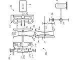
図1は、本発明の実施形態に係るエンジンルーム温度上昇抑制装置が適用される車両10の前部における要部構成を示す図である。なお、以下では、図示のように車両の前後方向および上下方向を定義するとともに、前後方向に垂直かつ上下方向に垂直な方向を左右方向と定義する。前後方向、上下方向および左右方向は、それぞれ車両10の進行方向、高さ方向および車幅方向に相当する。
FIG. 1 is a view showing a main part configuration of a front portion of a
図1に示すように、車両10の前部のエンジンルーム1には、エンジン2と後述する変速機とが配置され、変速機から出力されたトルクが駆動輪3に伝達される。車両10の最前部には、車両走行時の外気としての走行風(矢印Aで示す)を、ダクト4を介してエンジンルーム1内に導くためのフロントグリル5が設けられる。ダクト4は上下に分割され、各ダクト4の後端部に、ダクト4内の空気通路APを横断してそれぞれグリルシャッタ6が配置される。
As shown in FIG. 1, an
グリルシャッタ6は、左右方向に延在する複数の横長のフィン6aを有し、これらフィン6aは上下方向に配列される。各フィン6aは、左右方向に延在する回動軸を支点にして上下方向(矢印R1,R2方向)に回動可能に設けられ、フィン6aの回動により、ダクト4からエンジンルーム1に至る空気通路APが開閉される。すなわち、フィン6aが下方に回動して上下のフィン6aの一部が互いに重なり合うと(実線)、空気通路APが閉鎖され、エンジンルーム1への走行風Aの導入が阻止される。一方、フィン6aが上方に回動して水平姿勢になると(点線)、空気通路APが開放され、エンジンルーム1への走行風Aの導入が可能となる。
The grille shutter 6 has a plurality of horizontally
各フィン6aは、その後方に配置されたリンク7に連結される。リンク7は、電動モータなどのシャッタアクチュエータ8の駆動により上下方向(矢印L1,L2方向)に移動可能に設けられ、各フィン6aはリンク7の上下動に伴い、リンク7を介して同時に開放または閉鎖される。リンク7の後方には、ラジエータやコンデンサなどの熱交換器9が配置され、熱交換器9で走行風(冷却風)とエンジン冷却水や冷媒とが熱交換される。熱交換器9を通過した冷却風は、エンジンルーム1を通過し、外部に排出される。
Each
このように構成された車両10においては、車両の走行状態やエンジンルーム1の温度状態に基づいて、コントローラ30がシャッタアクチュエータ8を制御し、グリルシャッタ6を開閉する。グリルシャッタ6が正常に動作可能であれば、コントローラ30からの開指令に応じてグリルシャッタ6が開放され、これによりエンジンルーム1に外気が導入されて、エンジンルーム1の温度上昇を抑制することができる。
In the
一方、フィン6aやリンク7の駆動部への異物の噛み込みや固着、フィン6aやリンク7あるいはシャッタアクチュエータ8の故障、シャッタアクチュエータ8を駆動するための信号線の断線等により、グリルシャッタ6の開動作が不能になると、開指令に拘らずグリルシャッタ6が閉状態のままとなる。このようなグリルシャッタ6の閉じ故障が生じると、エンジンルーム1への外気の導入が阻止され、エンジンルーム1の温度が上昇する。その結果、エンジンルーム1に配置された各部品の温度が耐熱温度を上回るおそれがある。これを避けるためには、耐熱温度の高い部品を使用する必要性が生じ、その場合にはコストの上昇を招く。
On the other hand, of the grille shutter 6 due to biting or sticking of foreign matter to the drive portion of the fin 6a or the link 7, failure of the fin 6a or link 7 or the
そこで、グリルシャッタ6の閉じ故障時におけるエンジンルーム1の温度上昇を抑制するため、本実施形態では以下のようにエンジンルーム温度上昇抑制装置を構成する。 Then, in order to suppress the temperature rise of the engine room 1 at the time of closing failure of the grille shutter 6, the engine room temperature rise suppression device is configured as follows in this embodiment.
まず、本実施形態に係る車両10の駆動系の構成について説明する。図2は、車両10の駆動系の概略構成を示す図である。図2に示すように、エンジン2のクランクシャフトの回転は出力軸2aおよびトルクコンバータ11を介して自動変速機20に入力される。エンジン2は、空気に燃料(ガソリン)を噴射した混合気体を燃焼させるガソリンエンジンである。なお、ディーゼルエンジンをエンジン2として用いることもできる。
First, the configuration of the drive system of the
自動変速機20は、メインシャフト21と、メインシャフト21に平行なカウンタシャフト22とを有する。自動変速機20は、無段変速機により構成され、無段変速機構20aを有する。すなわち、メインシャフト21の外周側シャフトに配置されたドライブプーリ23と、カウンタシャフト22の外周側シャフトに配置されたドリブンプーリ24と、ドライブプーリ23とドリブンプーリ24との間に掛け回される動力伝達部材、例えば金属製のベルト25とを有する。
The
ドライブプーリ23は、メインシャフト21の外周側シャフトに相対回転不能かつ軸方向移動不能に配置された固定プーリ半体23aと、メインシャフト21の外周側シャフトに相対回転不能かつ固定プーリ半体23aに対し軸方向相対移動可能な可動プーリ半体23bとを有する。可動プーリ半体23bは、作動油室23cに作用する油圧力に応じて軸方向に押動される。ドリブンプーリ24は、カウンタシャフト22の外周側シャフトに相対回転不能かつ軸方向移動不能に配置された固定プーリ半体24aと、カウンタシャフト22に相対回転不能かつ固定プーリ半体24aに対し軸方向相対移動可能な可動プーリ半体24bとを有する。可動プーリ半体24bは、作動油室24cに作用する油圧力に応じて軸方向に押動される。各作動油室23c,24cには、制御弁(図3)により調圧された油圧が供給される。
The
無段変速機構20aは、前後進切換機構26を介してエンジン出力軸2aに接続される。前後進切換機構26は、車両10の前進方向への走行を可能にする前進クラッチ26aと、後進方向への走行を可能にする後進クラッチ26bとを有する。前進クラッチ26aと後進ブレーキクラッチ28bとは、車両運転席に設けられた不図示のレンジセレクタの操作に応じて切替えられる。
The continuously
前進クラッチ26aと後進クラッチ26bとの間には、プラネタリギヤ機構27が配置される。プラネタリギヤ機構27は、メインシャフト21に固定されたサンギヤ27aと、前進クラッチ26aを介してドライブプーリ23の固定プーリ半体23aに固定されたリングギヤ27bと、サンギヤ27aとリングギヤ27bとの間に配置され、キャリア27dにより回転可能に支持されたピニオン27cとを有する。カウンタシャフト22の回転は、ギヤを介してセカンダリシャフト28に伝達され、さらにギヤを介してディファレンシャル29から左右(一方のみ図示)の駆動輪3に伝達される。
A
図3は、本発明の実施形態に係るエンジンルーム温度上昇抑制装置100の概略構成を示すブロック図である。図3のコントローラ30は、エンジンコントロールユニットと変速機コントロールユニットとを含む。
FIG. 3 is a block diagram showing a schematic configuration of the engine room temperature rise suppression device 100 according to the embodiment of the present invention. The
図3に示すように、コントローラ30には、エンジン回転数Neを検出するエンジン回転数センサ31と、運転者により操作されるアクセルペダルの開度(アクセル開度Ac)を検出するアクセル開度センサ32と、車両の走行速度(車速v)を検出する車速センサ33と、ドライブプーリ23の回転数を検出するDR回転数センサ34と、ドリブンプーリ24の回転数を検出するDN回転数センサ35と、グリルシャッタ6の開閉状態を検出するシャッタ開閉センサ36と、変速機20に供給される作動油や潤滑油などの油の温度(油温To)を検出する油温センサ37と、エンジン冷却水の温度(冷却水温Tw)を検出する水温センサ38とからの信号が入力される。なお、コントローラ30には、吸気温度を検出する吸気温センサ等からの信号も入力されるが、図3ではその図示を省略する。
As shown in FIG. 3, the
コントローラ30は、これらの入力信号に基づいて所定の処理を実行し、グリルシャッタ駆動用のシャッタアクチュエータ8(図1)と、可動プーリ半体23b,24bに面した作動油室23c,24c(図2)へ供給される油圧を調圧する複数(図では1つのみ図示)の制御弁41と、運転席の前方に配置された表示部(例えばメータパネル)42と、スロットル開度を調節するスロットルモータ43とにそれぞれ制御信号を出力する。なお、コントローラ30は、燃料噴射弁や点火プラグ等にも制御信号を出力するが、図3ではその図示を省略する。
The
コントローラ30は、CPU,ROM,RAMその他の周辺回路を有する演算処理装置を含んで構成される。コントローラ30は、機能的構成として、主にシャッタ制御部30Aと、閉じ故障検出部30Bと、マップ記憶部30Cと、目標エンジン回転数演算部30Dと、変速比制御部30Eとを有する。
The
シャッタ制御部30Aは、水温センサ38などからの信号に基づいてシャッタアクチュエータ8に制御信号を出力し、グリルシャッタ6の開閉を制御する。すなわち、水温センサ38により検出された冷却水温Twが所定温度Twa以上になると、シャッタアクチュエータ8に開指令を出力し、閉状態にあるグリルシャッタ6を開放する。
The
閉じ故障検出部30Bは、シャッタ開閉センサ36からの信号に基づいてグリルシャッタ6の閉じ故障を検出する。すなわち、コントローラ30がシャッタアクチュエータ8に開指令を出力したにも拘らず、シャッタ開閉センサ36によりグリルシャッタ6の開状態が検出されないとき、閉じ故障検出部30Bはグリルシャッタ6が閉じ故障であると判定する。
The closing
マップ記憶部30Cは、無段変速機20に適用される変速マップを予め記憶する。図4は、マップ記憶部30Cに記憶される変速マップの一例を示す図である。変速マップは、車速vとアクセル開度Acとに対応する目標エンジン回転数Neaの関係を示したものである。図中の特性f1は、アクセルペダルの踏み込み量が最大(100%)であるアクセル開度Ac全開時の車速vと目標エンジン回転数Neaとの関係を示し、特性f2は、アクセルペダルの踏み込み量が最小(0%)であるアクセル開度Ac全閉時の車速vと目標エンジン回転数Neaとの関係を示す。
The
図示は省略するが、特性f1と特性f2との間には、アクセル開度Ac毎に車速vと目標エンジン回転数Neaとの関係を示す複数の特性、すなわち、アクセル開度Acが増加するほど特性f1に近づき、アクセル開度Acが減少するほど特性f2に近づくような複数の特性が設定され、これらはマップ記憶部30Cに記憶される。特性f10、f20は、それぞれ最小変速比と最大変速比の特性であり、変速比はこの特性f10、f20の間で変更可能である。なお、同一の車速vで比較すると、目標エンジン回転数Neaは、アクセル開度Acが大きいほど増大する。
Although illustration is omitted, a plurality of characteristics indicating the relationship between the vehicle speed v and the target engine rotational speed Nea for each accelerator opening Ac between the characteristic f1 and the characteristic f2, that is, as the accelerator opening Ac increases A plurality of characteristics are set so as to approach the characteristics f1 and to approach the characteristics f2 as the accelerator opening Ac decreases, and these are stored in the
本実施形態では、上述したアクセル開度Ac毎の特性(f1,f2など)に加え、グリルシャッタ閉じ故障時の目標エンジン回転数Neaの上限値を表す特性faと、油温Toが所定値Toa以上となったときの目標エンジン回転数Neaの上限値を表す特性fbとが、変速マップ上の特性として予めマップ記憶部30Cに記憶される。
In the present embodiment, in addition to the characteristics (f1, f2, etc.) for each accelerator opening Ac described above, the characteristic fa representing the upper limit of the target engine rotational speed Nea at the time of grill shutter closing failure, the oil temperature To has a predetermined value Toa A characteristic fb representing the upper limit value of the target engine speed Nea at the time of the above is stored in advance in the
特性faは、車速vが所定値v1(例えば40km/h)以下の低速域において、車速vの増加に伴い目標エンジン回転数Neaが徐々に低下し、車速vが所定値v1以上かつ所定値v2(例えば120km/h)以下の中速および高速域において、車速vの増加に伴い目標エンジン回転数Neaが徐々に増加し、その後、車速が所定値v2以上の領域で、車速vの増加に伴い目標エンジン回転数Neaが一定ないし緩やかに増加するように設定される。 In the characteristic fa, in a low speed range where the vehicle speed v is less than a predetermined value v1 (for example, 40 km / h), the target engine rotational speed Nea gradually decreases with an increase in the vehicle speed v, and the vehicle speed v is a predetermined value v1 or more and a predetermined value v2 The target engine rotational speed Nea gradually increases with the increase of the vehicle speed v in the medium and high speed regions (for example, 120 km / h or less) and thereafter with the increase of the vehicle speed v in the region where the vehicle speed is a predetermined value v2 or more. The target engine speed Nea is set to increase constantly or gradually.
このように低速域(例えば車速v0)で目標エンジン回転数Neaの上限値を高い値に設定することで、車両10を走行させるのに十分な走行駆動トルクを得ることができる。また、目標エンジン回転数の上限値を一旦下げて(車速v1)、その後、中速域から高速域にかけて目標エンジン回転数Neaを徐々に増加させることで、エンジンルーム1の温度上昇を抑えつつ、車両10を滑らかに加速走行させることができる。
By setting the upper limit value of the target engine rotational speed Nea to a high value in the low speed range (for example, the vehicle speed v0) as described above, it is possible to obtain traveling driving torque sufficient to cause the
図4において、特性fbは、車速vに拘らず一定の上限値Nea1に設定される。より具体的には、上限値Nea1は、グリルシャッタ閉じ故障時の目標エンジン回転数Neaの上限値(特性fa)よりも大きい値に設定される。この理由は、油温Toは、グリルシャッタ閉じ故障とは異なり時間の経過に伴い低下すると見込まれるため、グリルシャッタ閉じ故障時に比べエンジン回転数を大きく制限する必要がないからである。このように油温Toが所定値Toa以上のときの目標エンジン回転数Neaの上限値Nea1を、グリルシャッタ閉じ故障時の目標エンジン回転数Neaの上限値(特性fa)よりも高い値に設定することで、油温Toの上昇を抑えつつ、良好な走行性能を得ることができる。 In FIG. 4, the characteristic fb is set to a constant upper limit Nea1 regardless of the vehicle speed v. More specifically, the upper limit value Nea1 is set to a value larger than the upper limit value (characteristic fa) of the target engine rotational speed Nea at the time of the grill shutter closing failure. The reason for this is that since the oil temperature To is expected to decrease with the passage of time unlike the grill shutter closing failure, it is not necessary to greatly limit the engine speed as compared with the grill shutter closing failure. Thus, the upper limit Nea1 of the target engine speed Nea when the oil temperature To is equal to or higher than the predetermined value Toa is set to a value higher than the upper limit (characteristic fa) of the target engine speed Nea at the time of grill shutter closing failure. Thus, good running performance can be obtained while suppressing the rise of the oil temperature To.
目標エンジン回転数演算部30Dは、アクセル開度センサ32と車速センサ33と油温センサ37とからの信号に基づき、図4のアクセル開度Ac毎の変速マップを用いて目標エンジン回転数Neaを演算する。この場合、まず、図4の変速マップを用いて車速vとアクセル開度Acとに対応した目標エンジン回転数(以下、これを基準目標エンジン回転数Nea0と呼ぶ)を演算する。そして、グリルシャッタ6の閉じ故障が検出されず、かつ、油温Toが所定値Toa未満のとき、基準目標エンジン回転数Nea0をそのまま目標エンジン回転数Neaとして演算する。
The target engine rotational
一方、グリルシャッタ6の閉じ故障が検出されたときは、基準目標エンジン回転数Nea0と、図4の特性faによる目標エンジン回転数の上限値(以下、これを閉じ故障上限回転数Nea2と呼ぶ)との大小を判定する。そして、Nea0≦Nea2のときは、基準目標エンジン回転数Nea0をそのまま目標エンジン回転数Neaとして演算する。Nea0>Nea2のときは、閉じ故障上限回転数Nea2を目標エンジン回転数Neaとして演算する。 On the other hand, when the closing failure of the grille shutter 6 is detected, the upper limit value of the target engine rotation speed according to the reference target engine rotation speed Nea0 and the characteristic fa of FIG. 4 (hereinafter referred to as the closing failure upper limit rotation speed Nea2) Determine the size of the When Nea0 ≦ Nea2, the reference target engine speed Nea0 is calculated as it is as the target engine speed Nea. When Nea0> Nea2, the closed failure upper limit rotational speed Nea2 is calculated as the target engine rotational speed Nea.
グリルシャッタ6の閉じ故障が検出されず、かつ、油温Toが所定値Toa以上のときは、基準目標エンジン回転数Nea0と、図4の特性fbによる目標エンジン回転数の上限値(以下、これを油温上限回転数Nea1と呼ぶ)の大小を判定する。そして、Nea0≦Nea1のときは、基準目標エンジン回転数Nea0をそのまま目標エンジン回転数Neaとして演算する。Nea0>Nea1のときは、油温上限回転数Nea1を目標エンジン回転数Neaとして演算する。 When the closing failure of the grille shutter 6 is not detected and the oil temperature To is equal to or more than the predetermined value Toa, the reference target engine rotational speed Nea0 and the upper limit value of the target engine rotational speed according to the characteristic fb of FIG. Of the oil temperature upper limit rotational speed Nea1) is determined. When Nea0 ≦ Nea1, the reference target engine speed Nea0 is calculated as it is as the target engine speed Nea. When Nea0> Nea1, the oil temperature upper limit rotational speed Nea1 is calculated as the target engine rotational speed Nea.
変速比制御部30Eは、エンジン回転数センサ31により検出されたエンジン回転数Neが目標エンジン回転数Neaとなるように、回転数NeとNeaとの偏差に応じて制御弁41に制御信号を出力し、変速機20の変速比を制御する。例えば、アクセル開度Acの増大により目標エンジン回転数Neaが大きくなると、変速比をロー側に制御し、エンジン回転数Neを目標エンジン回転数Neaに近づける。なお、実際の変速比は、DR回転数センサ34とDN回転数センサ35とからの信号により算出できる。
The gear
図5は、予め定められたプログラムに従いコントローラ30で実行される処理の一例を示すフローチャートである。このフローチャートに示す処理は、例えばエンジンキースイッチのオンにより開始され、所定周期で繰り返される。
FIG. 5 is a flowchart showing an example of processing executed by the
まず、ステップS1で図3に示す各種センサからの信号を読み込む。次いで、ステップS2で、予め定められた図4の特性に従い、検出された車速vとアクセル開度Acとに応じた基準目標エンジン回転数Nea0を演算する。ステップS3では、閉じ故障検出部30Bでの処理により、グリルシャッタ6の閉じ故障が検出されたか否かを判定する。ステップS3で否定されるとステップS4に進み、検出された油温Toが所定値Toa以下か否かを判定する。ステップS4で肯定されるとステップS5に進み、基準目標エンジン回転数Nea0を目標エンジン回転数Neaに設定する。すなわち、シャッタ閉じ故障が検出されず、かつ、油温Toが所定値Toa以下であるときは、目標エンジン回転数Neaを制限する必要がないため、基準目標エンジン回転数Nea0をそのまま目標エンジン回転数Neaに設定する。
First, in step S1, signals from various sensors shown in FIG. 3 are read. Next, in step S2, a reference target engine rotational speed Nea0 corresponding to the detected vehicle speed v and the accelerator opening Ac is calculated according to the predetermined characteristic of FIG. In step S3, it is determined whether or not the closing failure of the grille shutter 6 is detected by the processing in the closing
一方、ステップS4で否定されるとステップS6に進み、基準目標エンジン回転数Nea0が油温上限回転数Nea1以下か否かを判定する。ステップS6で肯定されるとステップS5に進み、否定されるとステップS7に進む。ステップS7では、油温上限回転数Nea1を目標エンジン回転数Neaに設定する。すなわち、この場合には、油温Toの上昇を抑えるため、基準目標エンジン回転数Nea0と油温上限回転数Nea1のいずれか低い方の値を目標エンジン回転数Neaに設定する。 On the other hand, if the result of step S4 is negative, the process proceeds to step S6, in which it is determined whether the reference target engine speed Nea0 is less than or equal to the oil temperature upper limit speed Nea1. If affirmed by step S6, it will progress to step S5, and if denied, it will progress to step S7. In step S7, the oil temperature upper limit rotational speed Nea1 is set to the target engine rotational speed Nea. That is, in this case, in order to suppress the rise of the oil temperature To, either the reference target engine speed Nea0 or the oil temperature upper limit speed Nea1, whichever is lower, is set as the target engine speed Nea.
また、ステップS3で肯定されるとステップS8に進み、表示部42に制御信号を出力して表示部42にグリルシャッタ6の故障状態を表示させる。すなわち、運転者にグリルシャッタ閉じ故障が生じた旨を報知する。これにより運転者は、走行中にエンジン回転数と駆動トルクとが制限されることを認識できる。次いで、ステップS9で、基準目標エンジン回転数Nea0が故障上限回転数Nea2以下か否かを判定する。ステップS9で肯定されるとステップS5に進み、否定されるとステップS10に進む。ステップS10では、故障上限回転数Nea2を目標エンジン回転数Neaに設定する。すなわち、この場合には、エンジンルーム1の温度上昇を抑えるため、基準目標エンジン回転数Nea0と故障上限回転数Nea2のいずれか低い方の値を目標エンジン回転数Neaに設定する。
If the result in Step S3 is affirmative, the process proceeds to Step S8, where a control signal is output to the
ステップS5,ステップS7,ステップS10のいずれかで目標エンジン回転数Neaが設定されるとステップS11に進み、目標エンジン回転数Neaに応じて変速機20の変速比を制御する。すなわち、制御弁41に制御信号を出力して可動プーリ半体23b,24bを駆動し、エンジン回転数Neを目標エンジン回転数Neaに近づける。
When the target engine speed Nea is set in any of step S5, step S7, and step S10, the process proceeds to step S11, and the transmission gear ratio of the
本実施形態に係るグリルシャッタ温度上昇抑制装置の特徴的な動作をより具体的に説明する。図4に一部を示す特性f3は、アクセル開度Acが全開と全閉の間の所定値であるときの特性である。このアクセル開度Acの下、車速vaで走行している状態(点P1)において、アクセル開度Acが全開となった場合を想定する。このとき、車速vはすぐには上昇しないため、グリルシャッタ6が正常に開閉動作し、かつ、油温Toが所定値Toa以下であれば、目標エンジン回転数Neaが例えば特性f1上の点P2における回転数まで上昇し(ステップS5)、エンジン回転数Neがこの目標回転数となるように変速比がロー側に制御される(ステップS11)。 A characteristic operation of the grille shutter temperature rise suppression device according to the present embodiment will be more specifically described. A characteristic f3 partially shown in FIG. 4 is a characteristic when the accelerator opening Ac is a predetermined value between full opening and full closing. It is assumed that the accelerator opening Ac is fully opened in a state of traveling at the vehicle speed va (point P1) under the accelerator opening Ac. At this time, since the vehicle speed v does not immediately increase, the grille shutter 6 normally opens and closes, and if the oil temperature To is equal to or less than the predetermined value Toa, the target engine rotational speed Nea is, for example, a point P2 on the characteristic f1. The engine speed Ne is increased to the rotational speed at step S5, and the transmission gear ratio is controlled to the low side so that the engine rotational speed Ne becomes the target rotational speed (step S11).
一方、グリルシャッタ6が正常に動作している状態で、油温Toが所定値Toa以上であると、目標エンジン回転数Neaの上限値が特性fb上の油温上限回転数Nea1(点Pb)に制限される(ステップS7)。これによりエンジン回転数Neの上昇が抑えられ、油温Toの上昇を抑えることができる。また、グリルシャッタ6の閉じ故障が検出されると、目標エンジン回転数Neaが特性fa上の点Paにおける回転数に制限される(ステップS10)。これによりエンジン回転数Neの上昇がより一層抑えられ、エンジン2や変速機20の発熱を抑えることができ、エンジンルーム1の温度上昇を抑制することができる。
On the other hand, with the grille shutter 6 operating normally, when the oil temperature To is equal to or higher than the predetermined value Toa, the upper limit value of the target engine speed Nea is the oil temperature upper limit speed Nea1 (point Pb) on the characteristic fb. (Step S7). As a result, the increase in the engine speed Ne can be suppressed, and the increase in the oil temperature To can be suppressed. Further, when the closing failure of the grille shutter 6 is detected, the target engine rotational speed Nea is limited to the rotational speed at the point Pa on the characteristic fa (step S10). As a result, the rise of the engine rotational speed Ne can be further suppressed, the heat generation of the
本実施形態によれば以下のような作用効果を奏することができる。
(1)エンジンルーム温度上昇抑制装置100は、エンジン2とエンジン2の出力軸2aの回転数を無段階に変速して出力する無段変速機20とが配置されたエンジンルーム1内に開閉指令に応じて開閉するグリルシャッタ6を介して外気を導入する車両10における、エンジンルーム1の温度上昇を抑制するものである。このエンジンルーム温度上昇抑制装置100は、開指令に拘らずグリルシャッタ6が閉じられたままのグリルシャッタ閉じ故障を検出する閉じ故障検出部30Bと、閉じ故障検出部30Bによりグリルシャッタ閉じ故障が検出されると、グリルシャッタ閉じ故障が検出されないときよりも、エンジン回転数Neの上限値が制限されるように無段変速機20の変速比を制御する変速比制御部30Eと、を備える(図3)。
According to the present embodiment, the following effects can be achieved.
(1) The engine room temperature rise suppression device 100 issues an open / close command in the engine room 1 in which the continuously
この構成により、グリルシャッタ閉じ故障時にエンジン回転数Neが制限されるため、エンジンルーム1の温度上昇を抑えることができる。その結果、エンジンルーム1に配置された各部品の温度を、耐熱温度の高い高価な部品を使用することなく容易に耐熱温度以下に抑えることができる。また、無段変速機20は無段階に変速比を調節可能であるため、変速比を制御することでエンジン回転数Neを容易に所定回転数(目標エンジン回転数Nea)に制限することができる。
With this configuration, since the engine rotational speed Ne is limited at the time when the grille shutter is closed, the temperature rise in the engine room 1 can be suppressed. As a result, the temperature of each part disposed in the engine room 1 can be easily suppressed to the heatproof temperature or less without using an expensive part having a high heatproof temperature. In addition, since continuously
(2)エンジンルーム温度上昇抑制装置100は、車両10の走行速度(車速)vを検出する車速センサ33と、アクセル開度Acを検出するアクセル開度センサ32と、車両の走行速度vとアクセル開度Acと目標エンジン回転数Neaとの関係を示す変速マップ(図4)を記憶するマップ記憶部30Cと、車速センサ33により検出された走行速度vとアクセル開度センサ32により検出されたアクセル開度Acとに基づいて、マップ記憶部30Cに記憶された変速マップに従い目標エンジン回転数Neaを演算する目標エンジン回転数演算部30Dとをさらに備える(図3)。マップ記憶部30Cは、閉じ故障検出部に30Bによりグリルシャッタ閉じ故障が検出されたときの目標エンジン回転数Neaがグリルシャッタ閉じ故障が検出されないときの目標エンジン回転数Neaよりも低くなるような変速マップ(特性fa)を記憶し(図4)、変速比制御部30Eは、エンジン回転数Neが目標エンジン回転数演算部30Dで演算された目標エンジン回転数Neaとなるように無段変速機20の変速比を制御する(ステップS11)。
(2) The engine room temperature rise suppression device 100 includes a
このように変速マップを用いることで、シャッタグリル閉じ故障時の車速vとアクセル開度Acとに応じた目標エンジン回転数Neaの上限値を容易に設定することができる。また、目標エンジン回転数Neaに応じて無段変速機20の変速比を制御することで、エンジン回転数Neを容易に目標エンジン回転数Neaに制御することができる。
By using the shift map as described above, it is possible to easily set the upper limit value of the target engine rotational speed Nea according to the vehicle speed v and the accelerator opening Ac at the shutter grill closing failure. Further, by controlling the transmission gear ratio of the continuously
(3)エンジンルーム温度上昇抑制装置100は、無段変速機20に供給される油の温度Toを検出する油温センサ37をさらに備える(図3)。変速比制御部30Eは、油温センサ37により検出された油温Toが所定温度Toaを超えると、閉じ故障検出部30Bによりグリルシャッタ閉じ故障が検出されたときよりもエンジン回転数Neの上限値が大きくなるように(Nea1>Nea2)、無段変速機20の変速比を制御する。
(3) The engine room temperature rise suppression device 100 further includes an
この構成により、油温Toが所定値Toa以上となったときにエンジン回転数Neが制限されるため、油温Toの上昇を抑えることができる。また、油温上昇時のエンジン回転数の上限値Nea1は、グリルシャッタ閉じ故障時のエンジン回転数の上限値Nea2よりも大きいので、油温Toの上昇を抑えつつ、良好な走行性能を発揮できる。 With this configuration, when the oil temperature To becomes equal to or higher than the predetermined value Toa, the engine rotational speed Ne is limited, so that the rise of the oil temperature To can be suppressed. In addition, since the upper limit Nea1 of the engine rotational speed at the time of the oil temperature rise is larger than the upper limit Nea2 of the engine rotational speed at the time of the grill shutter closing failure, excellent running performance can be exhibited while suppressing the rise of the oil temperature To. .
上記実施形態は種々の形態に変形することができる。以下、変形例について説明する。上記実施形態では、シャッタ開閉センサ36からの信号に基づいて閉じ故障検出部30Bが開指令に拘らずグリルシャッタ6が閉じられたままのグリルシャッタ閉じ故障を検出するようにしたが、閉じ故障検出部の構成はこれに限らない。グリルシャッタ6を全閉と全開の2位置だけでなく、全閉と全開の間の任意の中間位置に調整可能とすることもできる。グリルシャッタ閉じ故障として、全閉状態だけでなく、全閉に近い状態を閉じ故障検出部が検出するようにしてもよい。上記実施形態では、グリルシャッタ6を上下2分割に設けたが、グリルシャッタの構成および配置はこれに限らない。
The above embodiments can be modified in various forms. Hereinafter, modified examples will be described. In the above embodiment, the closing
上記実施形態では、エンジン回転数が目標エンジン回転数演算部30Dで演算された目標エンジン回転数となるように変速比制御部30Eが無段変速機20の変速比を制御するようにしたが、グリルシャッタ閉じ故障が検出されたときに、これが検出されないときよりも、エンジン回転数の上限値が制限されるように無段変速機の変速比を制御するのであれば、変速比制御部の構成は上述したものに限らない。エンジン回転数でなくエンジン駆動力の上限値を制限してもよい。
In the above embodiment, the gear
上記実施形態では、走行速度検出部としての車速センサ33により検出された走行速度vと、アクセル開度検出部としてのアクセル開度センサ32により検出されたアクセル開度Acとに基づいて、マップ記憶部30Cに記憶された変速マップに従い目標エンジン回転数演算部30Dが目標エンジン回転数Neaを演算するようにしたが、目標エンジン回転数演算部の構成はこれに限らない。
In the above embodiment, the map memory is stored based on the traveling speed v detected by the
上記実施形態では、コントローラ30のマップ記憶部30Cに変速マップを記憶するようにしたが、コントローラ30の外部にマップ記憶部を設け、変速マップを記憶してもよい。グリルシャッタ閉じ故障時の目標エンジン回転数がグリルシャッタ閉じ故障でないときの目標エンジン回転数よりも低くなるように設定されるのであれば、変速マップの形態(例えば特性fa)は図4に示したものに限らずいかなるものでもよい。
In the above embodiment, the shift map is stored in the
上記実施形態では、油温検出部としての油温センサ37により無段変速機に20に供給される油の温度Toを検出し、検出された油温Toが所定温度Toaを超えると、グリルシャッタ閉じ故障が検出されたときよりも目標エンジン回転数Neaの上限値が大きくなるように(Nea1>Nea2)、無段変速機20の変速比を制御するようにしたが、油温が所定値以上のときのエンジン回転数の上限値とグリルシャッタ閉じ故障が検出されたときのエンジン回転数の上限値との関係はこれに限らない。
In the above embodiment, the temperature To of the oil supplied to the continuously
すなわち、以上の説明はあくまで一例であり、本発明の特徴を損なわない限り、上述した実施形態および変形例により本発明が限定されるものではない。上記実施形態と変形例の1つまたは複数を任意に組み合わせることも可能である。 That is, the above description is merely an example, and the present invention is not limited by the above-described embodiment and modifications as long as the features of the present invention are not impaired. It is also possible to arbitrarily combine one or more of the above-described embodiment and the modification.
1 エンジンルーム、2 エンジン、6 グリルシャッタ、10 車両、30B 閉じ故障検出部、30C マップ記憶部、30D 目標エンジン回転数演算部、30E 変速比制御部、32 アクセル開度センサ、33 車速センサ、36 シャッタ開閉センサ、37 油温センサ、41 制御弁、100 エンジンルーム温度上昇抑制装置 Reference Signs List 1 engine room, 2 engines, 6 grille shutters, 10 vehicles, 30B closed failure detection unit, 30C map storage unit, 30D target engine rotation speed calculation unit, 30E transmission ratio control unit, 32 accelerator opening sensor, 33 vehicle speed sensor, 36 Shutter open / close sensor, 37 oil temperature sensor, 41 control valve, 100 engine room temperature rise suppressor
Claims (1)
開指令に拘らず前記グリルシャッタが閉じられたままのグリルシャッタ閉じ故障を検出する閉じ故障検出部と、
前記閉じ故障検出部により前記グリルシャッタ閉じ故障が検出されると、前記グリルシャッタ閉じ故障が検出されないときよりも、エンジン回転数またはエンジン駆動力の上限値が制限されるように前記無段変速機の変速比を制御する変速比制御部と、
前記無段変速機に供給される油の温度を検出する油温検出部と、を備え、
前記変速比制御部は、前記油温検出部により検出された油温が所定温度を超えると、前記閉じ故障検出部により前記グリルシャッタ閉じ故障が検出されたときよりもエンジン回転数の上限値が大きくなるように前記無段変速機の変速比を制御することを特徴とするエンジンルーム温度上昇抑制装置。 In a vehicle in which external air is introduced into an engine room in which an engine and a continuously variable transmission for continuously changing the rotational speed of the output shaft of the engine and outputting the open air according to an open / close command via a grille shutter An engine room temperature rise suppressor for suppressing a temperature rise in the engine room,
A closing failure detection unit that detects a closing failure of the grill shutter while the grill shutter remains closed regardless of an open command;
If the grille shutter closing failure is detected by the closing failure detection unit, the continuously variable transmission is controlled such that the upper limit value of the engine speed or the engine driving force is restricted more than when the grille shutter closing failure is not detected. a gear ratio control unit for controlling the gear ratio,
An oil temperature detection unit that detects the temperature of oil supplied to the continuously variable transmission;
When the oil temperature detected by the oil temperature detection unit exceeds a predetermined temperature, the gear ratio control unit has an upper limit value of the engine rotational speed than when the grille shutter closure failure is detected by the closure failure detection unit. An engine room temperature rise suppression device characterized by controlling a gear ratio of the continuously variable transmission so as to be large.
Priority Applications (3)
| Application Number | Priority Date | Filing Date | Title |
|---|---|---|---|
| JP2016238933A JP6541636B2 (en) | 2016-12-09 | 2016-12-09 | Engine room temperature rise suppressor |
| US15/831,313 US10344854B2 (en) | 2016-12-09 | 2017-12-04 | Engine room temperature rise restricting apparatus |
| CN201711259269.1A CN108223152B (en) | 2016-12-09 | 2017-12-04 | Engine compartment temperature rise suppression device |
Applications Claiming Priority (1)
| Application Number | Priority Date | Filing Date | Title |
|---|---|---|---|
| JP2016238933A JP6541636B2 (en) | 2016-12-09 | 2016-12-09 | Engine room temperature rise suppressor |
Publications (2)
| Publication Number | Publication Date |
|---|---|
| JP2018096399A JP2018096399A (en) | 2018-06-21 |
| JP6541636B2 true JP6541636B2 (en) | 2019-07-10 |
Family
ID=62489026
Family Applications (1)
| Application Number | Title | Priority Date | Filing Date |
|---|---|---|---|
| JP2016238933A Active JP6541636B2 (en) | 2016-12-09 | 2016-12-09 | Engine room temperature rise suppressor |
Country Status (3)
| Country | Link |
|---|---|
| US (1) | US10344854B2 (en) |
| JP (1) | JP6541636B2 (en) |
| CN (1) | CN108223152B (en) |
Families Citing this family (6)
| Publication number | Priority date | Publication date | Assignee | Title |
|---|---|---|---|---|
| US10464412B2 (en) * | 2017-06-19 | 2019-11-05 | Ford Global Technologies, Llc | Methods and system for diagnosing a position of active grille shutters of a vehicle |
| DE102018114499B4 (en) * | 2018-06-18 | 2021-02-11 | Dr. Ing. H.C. F. Porsche Aktiengesellschaft | Motor vehicle bug |
| JP7067420B2 (en) * | 2018-10-31 | 2022-05-16 | トヨタ自動車株式会社 | Cooling system |
| KR102598318B1 (en) * | 2018-11-30 | 2023-11-06 | 현대자동차주식회사 | Active air flap control method for vehicle |
| DE102019106828B4 (en) * | 2019-03-18 | 2022-06-23 | Hbpo Gmbh | Device for closing a motor vehicle cooling module |
| DE102019118006A1 (en) * | 2019-07-03 | 2021-01-07 | Röchling Automotive SE & Co. KG | Active device for changing the aerodynamic properties of a vehicle |
Family Cites Families (14)
| Publication number | Priority date | Publication date | Assignee | Title |
|---|---|---|---|---|
| JPS59217051A (en) * | 1983-05-23 | 1984-12-07 | Toyota Motor Corp | Control for stepless speed change gear for car |
| JP3322110B2 (en) * | 1996-02-15 | 2002-09-09 | 日産自動車株式会社 | Transmission control device for continuously variable transmission |
| JP4931364B2 (en) * | 2005-04-06 | 2012-05-16 | 本田技研工業株式会社 | Control device for continuously variable transmission for vehicle |
| JP2009113665A (en) * | 2007-11-07 | 2009-05-28 | Toyota Motor Corp | Control device and control method for vehicle |
| JP4471018B2 (en) * | 2008-04-15 | 2010-06-02 | トヨタ自動車株式会社 | Control device for continuously variable transmission |
| US8469000B2 (en) * | 2010-02-24 | 2013-06-25 | Eaton Corporation | Supercharger with continuously variable drive system |
| JP5895893B2 (en) * | 2013-04-02 | 2016-03-30 | トヨタ自動車株式会社 | vehicle |
| JP6182965B2 (en) | 2013-05-09 | 2017-08-23 | トヨタ自動車株式会社 | vehicle |
| US10363811B2 (en) * | 2013-06-13 | 2019-07-30 | Ford Global Technologies, Llc | Vehicle speed controlled active grille shutter system |
| JP6019242B2 (en) * | 2013-09-13 | 2016-11-02 | ジヤトコ株式会社 | Control device for automatic transmission |
| JP5862692B2 (en) * | 2014-01-10 | 2016-02-16 | トヨタ自動車株式会社 | Hybrid vehicle |
| JP2015227134A (en) * | 2014-06-02 | 2015-12-17 | トヨタ自動車株式会社 | vehicle |
| KR102131721B1 (en) * | 2014-06-02 | 2020-07-08 | 두산인프라코어 주식회사 | Apparatus and method for controlling an engine |
| JP6156259B2 (en) * | 2014-06-10 | 2017-07-05 | トヨタ自動車株式会社 | Hybrid vehicle and control method thereof |
-
2016
- 2016-12-09 JP JP2016238933A patent/JP6541636B2/en active Active
-
2017
- 2017-12-04 US US15/831,313 patent/US10344854B2/en active Active
- 2017-12-04 CN CN201711259269.1A patent/CN108223152B/en active Active
Also Published As
| Publication number | Publication date |
|---|---|
| CN108223152A (en) | 2018-06-29 |
| CN108223152B (en) | 2020-10-23 |
| JP2018096399A (en) | 2018-06-21 |
| US20180163863A1 (en) | 2018-06-14 |
| US10344854B2 (en) | 2019-07-09 |
Similar Documents
| Publication | Publication Date | Title |
|---|---|---|
| JP6541636B2 (en) | Engine room temperature rise suppressor | |
| US9982776B2 (en) | Method for protecting clutch for dual clutch transmission | |
| US8545365B2 (en) | Vehicular power transmission control apparatus | |
| JP4664246B2 (en) | Engine control device for work vehicle | |
| KR101778642B1 (en) | Work machine | |
| WO2011118254A1 (en) | Hybrid vehicle control device | |
| US8210985B2 (en) | Vehicular power transmission control apparatus | |
| CN105683626B (en) | Speed-change control device and shifting control method | |
| US8388496B2 (en) | Vehicular power transmission control apparatus | |
| JP2013015216A (en) | Shift control method of vehicle with automatic manual transmission | |
| JP3700383B2 (en) | Hybrid vehicle cooling system | |
| JP2011084170A (en) | Hybrid vehicle | |
| JP3716607B2 (en) | Vehicle cooling device | |
| JP6428706B2 (en) | Vehicle control device | |
| JP2009185700A (en) | Cooling control device of vehicle drive system | |
| CN103291479A (en) | Combustion state control apparatus | |
| JP2006292055A (en) | Control device for multiple clutch-type transmission | |
| US10458541B1 (en) | Manual transmission shiftlock intervention | |
| JP6089937B2 (en) | Engine control device | |
| JP3438642B2 (en) | Vehicle control device | |
| JP6540345B2 (en) | Vehicle travel control method and vehicle travel control device | |
| JP4119223B2 (en) | Gear ratio control device for continuously variable transmission for vehicle | |
| JP2016142261A (en) | Controller of vehicle | |
| JP6348781B2 (en) | Vehicle control device | |
| JP4677783B2 (en) | Air conditioner control device for vehicle |
Legal Events
| Date | Code | Title | Description |
|---|---|---|---|
| A131 | Notification of reasons for refusal |
Free format text: JAPANESE INTERMEDIATE CODE: A131 Effective date: 20180626 |
|
| A521 | Written amendment |
Free format text: JAPANESE INTERMEDIATE CODE: A523 Effective date: 20180807 |
|
| A131 | Notification of reasons for refusal |
Free format text: JAPANESE INTERMEDIATE CODE: A131 Effective date: 20190108 |
|
| A521 | Written amendment |
Free format text: JAPANESE INTERMEDIATE CODE: A523 Effective date: 20190222 |
|
| TRDD | Decision of grant or rejection written | ||
| A01 | Written decision to grant a patent or to grant a registration (utility model) |
Free format text: JAPANESE INTERMEDIATE CODE: A01 Effective date: 20190604 |
|
| A61 | First payment of annual fees (during grant procedure) |
Free format text: JAPANESE INTERMEDIATE CODE: A61 Effective date: 20190611 |
|
| R150 | Certificate of patent or registration of utility model |
Ref document number: 6541636 Country of ref document: JP Free format text: JAPANESE INTERMEDIATE CODE: R150 |