JP6540672B2 - Hot water supply system - Google Patents

Hot water supply system Download PDF

Info

Publication number
JP6540672B2
JP6540672B2 JP2016236149A JP2016236149A JP6540672B2 JP 6540672 B2 JP6540672 B2 JP 6540672B2 JP 2016236149 A JP2016236149 A JP 2016236149A JP 2016236149 A JP2016236149 A JP 2016236149A JP 6540672 B2 JP6540672 B2 JP 6540672B2
Authority
JP
Japan
Prior art keywords
hot water
signal
water supply
closing
supply system
Prior art date
Legal status (The legal status is an assumption and is not a legal conclusion. Google has not performed a legal analysis and makes no representation as to the accuracy of the status listed.)
Active
Application number
JP2016236149A
Other languages
Japanese (ja)
Other versions
JP2018091568A (en
Inventor
雄斗 黒森
雄斗 黒森
風間 史郎
史郎 風間
智 赤木
智 赤木
真行 須藤
真行 須藤
明宏 戸田
明宏 戸田
Current Assignee (The listed assignees may be inaccurate. Google has not performed a legal analysis and makes no representation or warranty as to the accuracy of the list.)
Mitsubishi Electric Corp
Original Assignee
Mitsubishi Electric Corp
Priority date (The priority date is an assumption and is not a legal conclusion. Google has not performed a legal analysis and makes no representation as to the accuracy of the date listed.)
Filing date
Publication date
Application filed by Mitsubishi Electric Corp filed Critical Mitsubishi Electric Corp
Priority to JP2016236149A priority Critical patent/JP6540672B2/en
Publication of JP2018091568A publication Critical patent/JP2018091568A/en
Application granted granted Critical
Publication of JP6540672B2 publication Critical patent/JP6540672B2/en
Active legal-status Critical Current
Anticipated expiration legal-status Critical

Links

Images

Description

本発明は、給湯システムに関する。   The present invention relates to a hot water supply system.

従来、例えば特許文献1には、自動排水栓を備えた風呂システムの制御方法に関する技術が開示されている。このシステムでは、浴槽に設置された自動排水栓を駆動モータの作動制御によって閉駆動させた場合に、駆動モータの作動量検出値が開から閉への決められた作動量か否かによって閉作動異常か否かが判定される。   Conventionally, for example, Patent Document 1 discloses a technique related to a control method of a bath system provided with an automatic drain valve. In this system, when the automatic drain valve installed in the bathtub is driven to close by the operation control of the drive motor, the closing operation is performed depending on whether the operation amount detection value of the drive motor is a predetermined operation amount from open to closed. It is determined whether or not it is abnormal.

特開2002−206800号公報JP 2002-206800 A

上記従来のシステムでは、浴槽への湯張りを行う前に自動排水栓の閉作動異常を判定することとしている。湯張り動作等によって浴槽内に水が張られている状態では、自動排水栓を開状態から閉駆動させることができないからである。このように、上記従来のシステムでは、自動排水栓の作動異常を判定することができる場面が浴槽に水がない場面に限定されるという課題がある。   In the above-mentioned conventional system, it is decided to determine the closing operation abnormality of the automatic drain plug before the bathing is performed. This is because the automatic drain valve can not be driven to close from the open state in a state where water is kept in the bath by the pouring operation or the like. As described above, in the above-described conventional system, there is a problem that a scene where it is possible to determine an operation malfunction of the automatic drain plug is limited to a scene where there is no water in the bathtub.

本発明は、上述のような課題を解決するためになされたもので、浴槽に水があるか否かによらず、自動排水弁の動作不良を精度よく検知することができる給湯システムを提供することを目的とする。   The present invention has been made to solve the above-mentioned problems, and provides a hot water supply system capable of accurately detecting an operation failure of an automatic drain valve regardless of whether or not there is water in a bath. The purpose is

本発明に係る給湯システムは、浴槽の排水栓を電動で開閉する自動排水栓を備え、運転状態に応じた閉じ指令又は開き指令を受けて排水栓を自動で開閉する連携運転を行う給湯システムにおいて、排水栓が開状態のときには開信号を受信し、排水栓が閉状態のときには閉信号を受信する信号受信手段と、開信号及び閉信号に基づいて、自動排水栓の動作不良を検知する動作不良検知手段と、を備え、動作不良検知手段は、浴槽に水がある場合には閉じ指令が出されている状態で閉信号を受信しているか否かによって自動排水栓の動作不良を検知し、浴槽に水がない場合には閉じ指令が出されている状態で閉信号を受信しているか否か及び開き指令が出されている状態で開信号を受信しているか否かによって自動排水栓の動作不良を検知するように構成されているものである。   A hot water supply system according to the present invention includes an automatic drain valve electrically opening and closing a drain tap of a bathtub, and performs a linked operation to automatically open and close the drain valve in response to a closing command or an open command according to the operating condition. An operation for detecting an operation failure of the automatic drainage plug based on signal receiving means for receiving an opening signal when the drainage plug is open and receiving a closing signal when the drainage plug is closed, and based on the opening signal and the closing signal. The operation failure detection unit detects the operation failure of the automatic drain valve according to whether or not the closing signal is received in a state where the closing command is issued when there is water in the bathtub. If there is no water in the bath tub, the automatic drain valve will be received depending on whether the close signal is received in the state where the close command is issued and whether the open signal is received in the state where the open command is issued. Detect a malfunction of the Those that are configured.

本発明の給湯システムによれば、浴槽に水があるか否かによらず、自動排水弁の動作不良を高精度に検知する故障有無を精度よく検知することが可能となる。   According to the hot water supply system of the present invention, it becomes possible to accurately detect the presence or absence of a failure which detects the malfunction of the automatic drainage valve with high accuracy regardless of whether the bath has water or not.

実施の形態1における給湯システムとしての貯湯式給湯機の構成図である。FIG. 1 is a configuration diagram of a hot water storage type hot water supply as a hot water supply system in a first embodiment. 自動排水栓の故障確認運転のルーチンを示すフローチャートである。It is a flowchart which shows the routine of failure confirmation driving | operation of an automatic drain valve.

以下、図面を参照して実施の形態について説明する。   Hereinafter, embodiments will be described with reference to the drawings.

実施の形態1.
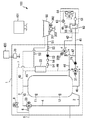
図1は、実施の形態1における給湯システムとしての貯湯式給湯機100の構成図である。図1に示す貯湯式給湯機100は、貯湯タンクユニット1と、ヒートポンプサイクルを利用するように構成されたヒートポンプユニット60とを備えている。2つのユニット1、60は、ヒートポンプ入口配管41とヒートポンプ出口配管42とによって接続されている。また、貯湯タンクユニット1には、制御部70が内蔵されている。貯湯タンクユニット1およびヒートポンプユニット60が備える各種の弁類、ポンプ類等の作動は、これらと配線を介して接続された制御部70により制御される。以下、貯湯式給湯機100の各構成要素について説明する。
Embodiment 1
FIG. 1 is a block diagram of a hot water storage type water heater 100 as a hot water supply system in the first embodiment. A hot water storage type water heater 100 shown in FIG. 1 includes a hot water storage tank unit 1 and a heat pump unit 60 configured to use a heat pump cycle. The two units 1 and 60 are connected by the heat pump inlet pipe 41 and the heat pump outlet pipe 42. In addition, the hot water storage tank unit 1 incorporates a control unit 70. The operation of various valves, pumps, and the like included in the hot water storage tank unit 1 and the heat pump unit 60 is controlled by a control unit 70 connected thereto via a wire. Hereinafter, each component of the hot water storage type water heater 100 will be described.

ヒートポンプユニット60は、貯湯タンクユニット1から導かれた低温水を加熱するための加熱手段として機能するものである。ヒートポンプユニット60は、圧縮機61、沸き上げ用熱交換器62、膨張弁63、空気熱交換器64を冷媒循環配管65にて環状に接続し、ヒートポンプサイクルを構成している。沸き上げ用熱交換器62は、ヒートポンプサイクルを構成する冷媒循環配管65を流れる冷媒と貯湯タンクユニット1から導かれた低温水との間で熱交換を行うためのものである。また、HP出口側サーミスタ66は、沸き上げ用熱交換器62で加熱した高温水の温度を検知するための温度センサであり、ヒートポンプ出口配管42に設けられている。ヒートポンプユニット60で高温水を得るためには、ヒートポンプサイクルは、冷媒として二酸化炭素を用い、臨界圧を越える圧力で運転することが好ましい。   The heat pump unit 60 functions as a heating means for heating the low temperature water led from the hot water storage tank unit 1. The heat pump unit 60 forms a heat pump cycle by annularly connecting a compressor 61, a heat exchanger 62 for boiling, an expansion valve 63, and an air heat exchanger 64 through a refrigerant circulation pipe 65. The boiling heat exchanger 62 is for performing heat exchange between the refrigerant flowing through the refrigerant circulation pipe 65 constituting the heat pump cycle and the low temperature water led from the hot water storage tank unit 1. The HP outlet-side thermistor 66 is a temperature sensor for detecting the temperature of the high-temperature water heated by the boiling heat exchanger 62, and is provided in the heat pump outlet pipe 42. In order to obtain high temperature water by the heat pump unit 60, it is preferable to operate the heat pump cycle at a pressure exceeding the critical pressure, using carbon dioxide as the refrigerant.

一方、貯湯タンクユニット1には、以下の各種部品及び配管などが内蔵されている。貯湯タンク10は、湯水を貯留するためのものである。貯湯タンク10の下部には、市水を供給するための給水配管2が接続されている。貯湯タンク10の上部には、貯留した湯水を給湯機外部へ供給するための給湯湯側配管3がタンク上部配管43から分岐されて接続されている。尚、貯湯タンク10には、ヒートポンプユニット60を用いて加熱された高温水がタンク上部から流入されるとともに、給水配管2を介して低温水をタンク下部から流入させることにより、タンク内の上部と下部で温度差が生じるように湯水が貯留される。また、貯湯タンク10の表面の上部および下部には、貯湯タンク10内の湯水の温度分布を検知するための残湯サーミスタ11、12がそれぞれ取り付けられている。これらの残湯サーミスタ11、12により取得された温度分布に基づいて、貯湯タンク10内の残湯量が把握され、ヒートポンプユニット60による貯湯タンク10内の湯水の沸き上げ運転の開始および停止などが制御される。   On the other hand, the following various parts and piping etc. are incorporated in the hot water storage tank unit 1. The hot water storage tank 10 is for storing hot and cold water. A water supply pipe 2 for supplying city water is connected to the lower portion of the hot water storage tank 10. A hot water supply side pipe 3 for supplying stored hot water to the outside of the water heater is branched from a tank upper pipe 43 and connected to an upper portion of the hot water storage tank 10. In the hot water storage tank 10, high temperature water heated using the heat pump unit 60 flows in from the upper part of the tank, and low temperature water flows in from the lower part of the tank through the water supply pipe 2 Hot and cold water is stored so that a temperature difference occurs at the lower part. In addition, residual water thermistors 11 and 12 for detecting the temperature distribution of hot and cold water in the hot water storage tank 10 are attached to upper and lower portions of the surface of the hot water storage tank 10, respectively. The amount of remaining hot water in the hot water storage tank 10 is grasped based on the temperature distribution acquired by these residual hot water thermistors 11 and 12, and start and stop of the boiling operation of hot water in the hot water storage tank 10 by the heat pump unit 60 are controlled. Be done.

タンク上部配管43から分岐されて接続されている給湯湯側配管3は、給水配管2から分岐した給湯水側配管4とともに給湯混合弁33に接続されている。給湯混合弁33は、給湯湯側配管3を流れる湯と給湯水側配管4を流れる水とを混合し、温度調整された湯水を給湯配管5から外部水栓等の給湯端末へ供給する。また、給湯配管5には、給湯混合弁33から出た給湯水の温度を検知するための給湯温度サーミスタ6が取り付けられている。   The hot water supply side pipe 3 branched and connected from the tank upper pipe 43 is connected to the hot water supply mixing valve 33 together with the hot water supply side pipe 4 branched from the water supply pipe 2. The hot water supply mixing valve 33 mixes the hot water flowing in the hot water supply side pipe 3 and the water flowing in the hot water supply water side pipe 4 and supplies the temperature-controlled hot water with the hot water supply pipe 5 to a hot water supply terminal such as an external faucet. A hot water supply temperature thermistor 6 for detecting the temperature of the hot water supplied from the hot water supply mixing valve 33 is attached to the hot water supply pipe 5.

また、貯湯タンクユニット1内には、循環ポンプ21および利用側熱交換器22が内蔵されている。循環ポンプ21は、貯湯タンクユニット1内の後述する各種配管に湯水を循環させるためのポンプである。利用側熱交換器22は、貯湯タンク10又はヒートポンプユニット60から供給される高温水を利用して、2次側の加熱対象水を加熱するための熱交換器である。尚、本実施形態では、利用側熱交換器22の2次側の構成として、浴槽50内の水を循環させる浴槽水循環回路51が設けられている。上記利用側熱交換器22は、浴槽水循環回路51の途中に設置されている。また、浴槽水循環回路51の途中には、浴槽水を循環させるための2次側循環ポンプ52と、浴槽50から出た浴槽水の水温を検出するための浴槽出口側サーミスタ53がそれぞれ設置されている。また、浴槽水循環回路51の途中には、浴槽50の水位を検出するための水位センサ54と、浴槽50へ入る浴槽水の水温を検出するための浴槽入口側サーミスタ55と、浴槽水循環回路51の水流の有無を検出する浴槽水検出センサ56がそれぞれ設置されている。   Further, in the hot water storage tank unit 1, a circulation pump 21 and a use side heat exchanger 22 are incorporated. The circulation pump 21 is a pump for circulating hot and cold water through various pipes in the hot water storage tank unit 1 described later. The use side heat exchanger 22 is a heat exchanger for heating the water to be heated on the secondary side using the high temperature water supplied from the hot water storage tank 10 or the heat pump unit 60. In addition, in this embodiment, the bathtub water circulation circuit 51 which circulates the water in the bathtub 50 is provided as a structure of the secondary side of the utilization side heat exchanger 22. As shown in FIG. The use side heat exchanger 22 is installed in the middle of the bathtub water circulation circuit 51. Further, in the middle of the bathtub water circulation circuit 51, a secondary side circulation pump 52 for circulating bathtub water and a bathtub outlet side thermistor 53 for detecting the temperature of the bathtub water discharged from the bathtub 50 are respectively installed. There is. In the middle of the bathtub water circulation circuit 51, a water level sensor 54 for detecting the water level of the bathtub 50, a bathtub inlet side thermistor 55 for detecting the water temperature of the bathtub water entering the bathtub 50, and the bathtub water circulation circuit 51. A bathtub water detection sensor 56 for detecting the presence or absence of the water flow is respectively installed.

浴槽50内の底部には排水栓301が設置されている。排水栓301は、制御部70からの指示を受けて排水栓開閉モータ302を駆動することによって開閉駆動される。なお、以下の説明では、排水栓301及びこれを電動で開閉する排水栓開閉モータ302を含めて「自動排水栓」と称する。実施の形態1の貯湯式給湯機100では、沸き上げ運転等の運転状態に応じた閉じ指令及び開き指令を受けて、自動排水栓の排水栓301を自動で開閉する連携運転が行われる。   At the bottom of the bathtub 50, a drainage plug 301 is installed. The drainage plug 301 is driven to open and close by driving the drainage plug opening / closing motor 302 in response to an instruction from the control unit 70. In the following description, the drainage plug 301 and the drainage plug opening / closing motor 302 for electrically opening and closing the drainage plug 301 are referred to as “automatic drainage plug”. In the storage-type water heater 100 according to the first embodiment, in response to the closing command and the opening command according to the operation state such as the boiling operation, linked operation is performed in which the drainage plug 301 of the automatic drainage plug is automatically opened and closed.

排水栓301は、栓体が上下方向に移動可能に支持されている。作動量検出手段303は、排水栓301が開閉駆動制御された際の上下方向の作動量を検出する。作動量検出手段303は、検出された作動量から排水栓301の開閉状態を判断し、これを開閉作動状態に関する情報として中継ユニット401に出力するように構成されている。なお、作動量検出手段303及びこれを用いた制御については詳細を後述する。   The drainage plug 301 is supported so that the plug can move in the vertical direction. The operation amount detection means 303 detects the amount of operation in the vertical direction when the drain plug 301 is controlled to open and close. The operation amount detection means 303 is configured to determine the open / close state of the drainage plug 301 from the detected operation amount, and to output this to the relay unit 401 as information regarding the open / close operation state. The details of the operation amount detection means 303 and the control using the same will be described later.

中継ユニット401は、制御部70と排水栓301の作動量検出手段303とに接続されている。中継ユニット401は、それぞれから受信した信号をそれぞれの機器で判別可能な信号に変換するとともに、それぞれの機器との間で信号の授受を行う。   The relay unit 401 is connected to the control unit 70 and the operation amount detection means 303 of the drainage plug 301. The relay unit 401 converts signals received from the respective devices into signals distinguishable by the respective devices, and exchanges signals with the respective devices.

次に、貯湯タンクユニット1が備える弁類および配管類について説明する。貯湯タンクユニット1は、三方弁31および四方弁200を有している。三方弁31は、湯水が流入する2つの入口であるaポート及びbポートと、湯水が流出する1つの出口であるcポートとを有する流路切替手段である。三方弁31は、aポートもしくはbポートのどちらかから湯水が流入するように湯水の経路を切り替え可能に構成されている。四方弁200は、湯水が流入する2つの入口であるbポート及びcポートと、湯水が流出する2つの出口であるaポート及びdポートとを有する流路切替手段である。四方弁200は、3つの経路、すなわち、c−a経路、c−d経路、およびb−a経路の間で流路形態を切り替え可能に構成されている。   Next, the valves and piping provided in the hot water storage tank unit 1 will be described. The hot water storage tank unit 1 has a three-way valve 31 and a four-way valve 200. The three-way valve 31 is a flow path switching unit having two ports, an inlet a and a port b, into which hot water flows, and a port c, one outlet from which the hot water flows. The three-way valve 31 is configured to be able to switch the path of the hot water so that the hot water flows in from either the a port or the b port. The four-way valve 200 is a flow path switching unit having b ports and c ports, which are two inlets into which hot water flows, and two ports, a and d, which are outlets from which the hot water flows out. The four-way valve 200 is configured to be able to switch the flow channel configuration among three paths, that is, the c-a path, the c-d path, and the b-a path.

また、貯湯タンクユニット1は、タンク下部配管40、上記ヒートポンプ入口配管41、上記ヒートポンプ出口配管42、タンク上部配管43、タンク戻し配管44、利用側熱交換器1次側入口配管45、利用側熱交換器1次側出口配管46およびバイパス配管47を有している。   Further, the hot water storage tank unit 1 includes a tank lower piping 40, the heat pump inlet piping 41, the heat pump outlet piping 42, a tank upper piping 43, a tank return piping 44, a utilization side heat exchanger primary side inlet piping 45, utilization side heat An exchanger primary outlet pipe 46 and a bypass pipe 47 are provided.

より具体的には、タンク下部配管40は、貯湯タンク10の下部と三方弁31のaポートとを接続する流路である。また、ヒートポンプ入口配管41は、三方弁31のcポートとヒートポンプユニット60の入口側とを接続する流路である。また、ヒートポンプ出口配管42は、ヒートポンプユニット60の出口側と四方弁200のcポートとを接続する流路である。また、タンク上部配管43は、四方弁200のdポートと貯湯タンク10上部とを接続する流路である。そして、タンク戻し配管44は、四方弁200のaポートと貯湯タンク10の中央部から下部の間に設けられた戻し口とを接続する流路である。また、利用側熱交換器1次側入口配管45は、タンク上部配管43における貯湯タンク上部と四方弁200との間から分岐し、利用側熱交換器22の1次側入口に接続される流路である。また、利用側熱交換器1次側出口配管46は、利用側熱交換器22の1次側出口と三方弁31のbポートとを接続する流路である。更に、バイパス配管47は、ヒートポンプ入口配管41における循環ポンプ21の出口側の部位と四方弁200のbポートとを接続する流路である。尚、上記循環ポンプ21は、ヒートポンプ入口配管41上におけるバイパス配管47との接続部と三方弁31との間に設置されている。   More specifically, the lower tank pipe 40 is a flow path connecting the lower portion of the hot water storage tank 10 and the a port of the three-way valve 31. The heat pump inlet pipe 41 is a flow path connecting the c port of the three-way valve 31 and the inlet side of the heat pump unit 60. The heat pump outlet pipe 42 is a flow path connecting the outlet side of the heat pump unit 60 and the c port of the four-way valve 200. Further, the tank upper pipe 43 is a flow path connecting the d port of the four-way valve 200 and the upper portion of the hot water storage tank 10. The tank return pipe 44 is a flow path connecting the a port of the four-way valve 200 and a return port provided between the central portion and the lower portion of the hot water storage tank 10. In addition, the utilization side heat exchanger primary side inlet piping 45 is branched from between the hot water storage tank upper portion and the four-way valve 200 in the tank upper piping 43 and is connected to the primary side inlet of the utilization side heat exchanger 22 It is a road. In addition, the use side heat exchanger primary side outlet piping 46 is a flow path connecting the primary side outlet of the use side heat exchanger 22 and the b port of the three-way valve 31. Furthermore, the bypass pipe 47 is a flow path that connects the portion of the heat pump inlet pipe 41 on the outlet side of the circulation pump 21 and the b port of the four-way valve 200. The circulation pump 21 is disposed between a connection portion of the heat pump inlet pipe 41 with the bypass pipe 47 and the three-way valve 31.

また、貯湯タンクユニット1は、ふろ給湯配管7と電磁弁8を有している。ふろ給湯配管7は、給湯配管5と浴槽水循環回路51における利用側熱交換器22の下流側とを接続している。電磁弁8は、ふろ給湯配管7の途中に配置されている。   Further, the hot water storage tank unit 1 has a bath hot water supply pipe 7 and a solenoid valve 8. The bath hot water supply piping 7 connects the hot water supply piping 5 and the downstream side of the use-side heat exchanger 22 in the bathtub water circulation circuit 51. The solenoid valve 8 is disposed in the middle of the bottom hot water supply pipe 7.

実施の形態1の貯湯式給湯機100では、運転状態に応じて三方弁31及び四方弁200を制御して、貯湯タンクユニット1内の湯水の流路を切り替えて使用するようになっている。制御部70は、沸き上げ運転を実行する機能を備えている。なお、ここでいう沸き上げ運転とは、ヒートポンプユニット60を利用して貯湯タンク10内の水を沸き上げる運転のことである。この沸き上げ運転時には、三方弁31は、aポートとcポートとが連通しbポートが閉状態となるように制御される。これにより、タンク下部配管40とヒートポンプ入口配管41とが連通するとともに、利用側熱交換器1次側出口配管46側を閉として利用側熱交換器22からの流路が遮断される。また、沸き上げ運転時には、四方弁200は、cポートとdポートとが連通しaポートとbポートとが閉状態となるように制御される。これにより、ヒートポンプ出口配管42とタンク上部配管43とが連通するとともに、タンク戻し配管44側を閉として貯湯タンク10の下部への流路が遮断される。   In the hot water storage type hot water supply system 100 of the first embodiment, the three-way valve 31 and the four-way valve 200 are controlled according to the operating state, and the hot water passage in the hot water storage tank unit 1 is switched and used. The control unit 70 has a function of executing a boiling operation. In addition, the boiling operation said here is an operation which boils the water in the hot water storage tank 10 using the heat pump unit 60. As shown in FIG. During the boiling operation, the three-way valve 31 is controlled such that the a port and the c port communicate with each other and the b port is in a closed state. As a result, the tank lower pipe 40 and the heat pump inlet pipe 41 communicate with each other, and the flow path from the use side heat exchanger 22 is blocked by closing the use side heat exchanger primary side outlet pipe 46 side. In addition, during the boiling operation, the four-way valve 200 is controlled such that the c port and the d port communicate with each other and the a port and the b port are in the closed state. As a result, the heat pump outlet piping 42 and the tank upper piping 43 communicate with each other, and the tank return piping 44 side is closed to shut off the flow path to the lower part of the hot water storage tank 10.

沸き上げ運転は、上記のように三方弁31および四方弁200が制御された状態で、循環ポンプ21とヒートポンプユニット60の運転を開始することにより実行される。その結果、貯湯タンク10の下部から流出する低温の水は、タンク下部配管40、三方弁31、循環ポンプ21およびヒートポンプ入口配管41を経由してヒートポンプユニット60に導かれる。そして、ヒートポンプユニット60に流入した低温の水は、沸き上げ用熱交換器62において加熱されて高温の水となる。加熱された高温の水は、ヒートポンプ出口配管42、四方弁200およびタンク上部配管43を経由して、貯湯タンク10の上部から当該貯湯タンク10内に流入し蓄積される。このような沸き上げ運転が実行されることで、貯湯タンク10の内部では、上層部から高温水が貯えられていき、この高温水層が徐々に厚くなる。   The boiling operation is performed by starting the operation of the circulation pump 21 and the heat pump unit 60 in a state where the three-way valve 31 and the four-way valve 200 are controlled as described above. As a result, low temperature water flowing out from the lower part of the hot water storage tank 10 is led to the heat pump unit 60 via the lower tank pipe 40, the three-way valve 31, the circulation pump 21 and the heat pump inlet pipe 41. And the low temperature water which flowed into the heat pump unit 60 is heated in the heat exchanger 62 for boiling, and turns into high temperature water. The heated high-temperature water flows from the upper portion of the hot water storage tank 10 into the hot water storage tank 10 via the heat pump outlet piping 42, the four-way valve 200, and the tank upper piping 43 and is accumulated. By performing such a boiling operation, high temperature water is stored from the upper layer portion inside the hot water storage tank 10, and the high temperature water layer gradually becomes thick.

また、制御部70は、湯張り運転を実行する機能を備えている。なお、ここでいう湯張り運転とは、貯湯タンク10内に蓄えた高温の水を浴槽50に給湯する運転のことである。この湯張り運転時には、電磁弁8が開弁されることにより、給湯配管5からふろ給湯配管7及び浴槽水循環回路51を介して浴槽50へと連通する流路が形成される。制御部70は、給湯温度サーミスタ6によって検出される給湯温度が目標温度となるように給湯混合弁33を調整する。   Moreover, the control part 70 is provided with the function to perform a pouring operation. In addition, the hot water filling operation referred to here is an operation in which the high temperature water stored in the hot water storage tank 10 is supplied to the bath 50. At the time of this pouring operation, the electromagnetic valve 8 is opened to form a flow path communicating from the hot water supply pipe 5 to the bathtub 50 through the bath-hot water supply piping 7 and the bathtub water circulation circuit 51. The control unit 70 adjusts the hot water supply mixing valve 33 such that the hot water supply temperature detected by the hot water supply temperature thermistor 6 becomes the target temperature.

実施の形態1の貯湯式給湯機100は、リモコン400を備えている。リモコン400は、例えば浴室又は台所等に設置されるものであり、通信線を介して制御部70と接続されている。リモコン400には、貯湯式給湯機100の各種状態を表示するための図示しない表示部とスピーカとが設けられている。また、リモコン400には各種ボタンが設けられている。使用者は、これらの各種ボタンを操作することにより、湯張り運転の湯温、水位又は湯量の設定、運転開始指示等を行うことができる。   The hot water storage type hot water supply system 100 of the first embodiment is provided with a remote control 400. The remote control 400 is installed in, for example, a bathroom or a kitchen, and is connected to the control unit 70 via a communication line. The remote controller 400 is provided with a display unit and a speaker (not shown) for displaying various states of the hot water storage type water heater 100. Further, the remote controller 400 is provided with various buttons. By operating these various buttons, the user can perform setting of the water temperature, water level or amount of the water filling operation, an instruction to start the operation, and the like.

次に、実施の形態1の貯湯式給湯機100の特徴的動作について説明する。実施の形態1の貯湯式給湯機100は、自動排水栓の動作不良を検知する制御に特徴を有している。以下、この制御を行う運転を「故障確認運転」と称する。作動量検出手段303は、通電及び非通電の間で切り替わる状態信号を中継ユニット401に出力する。より詳しくは、作動量検出手段303は、排水栓301が完全に閉められた閉状態のときに、通電ONの通電信号を閉信号として出力し続ける。また、作動量検出手段303は、排水栓301が少しでも開いている開状態のときには、通電OFFの非通電信号を開信号として出力し続ける。   Next, the characteristic operation of the hot water storage type hot water supply system 100 of the first embodiment will be described. The hot water storage type hot water supply system 100 according to the first embodiment is characterized in control for detecting an operation failure of an automatic drain valve. Hereinafter, the operation for performing this control is referred to as "fault confirmation operation". The actuation amount detection means 303 outputs, to the relay unit 401, a state signal that switches between energization and non-energization. More specifically, when the drainage plug 301 is in a closed state in which the drainage plug 301 is completely closed, the actuation amount detection means 303 continues to output an energization signal of energization on as a closing signal. In addition, when the drainage plug 301 is in the open state in which the drainage plug 301 is slightly open, the operation amount detection means 303 continues to output the non-energization signal of the energization OFF as the open signal.

中継ユニット401に出力された状態信号は、制御部70に送られて自動排水栓の故障確認運転に使用される。以下、フローチャートに沿って自動排水栓の故障確認運転において実行されるルーチンの具体的処理について説明する。   The status signal output to the relay unit 401 is sent to the control unit 70 and used for failure confirmation operation of the automatic drain valve. Hereinafter, the specific process of the routine executed in the failure confirmation operation of the automatic drain plug will be described along the flowchart.

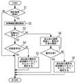
図2は、自動排水栓の故障確認運転のルーチンを示すフローチャートである。図2に示すルーチンは、湯張り運転の開始指示がユーザから出された場合に制御部70によって繰り返し実行される。図2に示すルーチンのステップS1では、予め設定された設定時間が経過したか否かが判定される。ここでの設定時間は、湯張り運転に連携した自動排水栓の動作が完了して実際に湯張りが開始されるまでの時間として、予め設定された値が読み込まれる。その結果、設定時間が未だ経過していないと判定された場合には、本ルーチンは終了されて、再度本ルーチンが開始される。一方、上記ステップS1において設定時間が経過したと判定された場合には、ステップS2に移行する。   FIG. 2 is a flow chart showing a routine of failure confirmation operation of the automatic drain valve. The routine shown in FIG. 2 is repeatedly executed by the control unit 70 when an instruction to start the pouring operation is issued from the user. In step S1 of the routine shown in FIG. 2, it is determined whether a preset set time has elapsed. As the setting time here, a value set in advance is read as the time until the operation of the automatic drain valve linked to the pouring operation is completed and the pouring is actually started. As a result, when it is determined that the set time has not elapsed yet, the present routine is ended and the present routine is started again. On the other hand, if it is determined in step S1 that the set time has elapsed, the process proceeds to step S2.

次のステップS2では、自動排水弁の故障確認運転が開始される。故障確認運転が開始されると、先ずはステップS3に移行して、浴槽50内に湯があるか否かが判定される。ここでは、具体的には、2次側循環ポンプ52を駆動した際に浴槽水検出センサ56によって水流が検知されるか否かが判定される。その結果、浴槽水検出センサ56によって水流が検知された場合には、浴槽50内に水があると判断することができる。この場合、ステップS4に移行して、自動排水弁への閉じ指令が出されている状態で通電ONの状態信号を受信しているか否かが判定される。その結果、通電ONの状態信号を受信している場合には、排水栓301が閉じられていると判断することができる。この場合、自動排水栓に動作不良は発生していないと判断することができるので、本ルーチンは終了される。   In the next step S2, failure confirmation operation of the automatic drainage valve is started. When the failure confirmation operation is started, first, the process proceeds to step S3, and it is determined whether there is hot water in the bathtub 50 or not. Here, specifically, it is determined whether or not the water flow is detected by the bath water detection sensor 56 when the secondary circulation pump 52 is driven. As a result, when the water flow is detected by the bathtub water detection sensor 56, it can be determined that there is water in the bathtub 50. In this case, the process proceeds to step S4, and it is determined whether the energization ON state signal is received while the closing command to the automatic drain valve is being issued. As a result, when the power on state signal is received, it can be determined that the drain plug 301 is closed. In this case, it can be determined that no malfunction has occurred in the automatic drain plug, so this routine is ended.

一方、上記ステップS4において、通電の状態信号を受信していない場合、すなわち非通電の信号を受信している場合には、閉じ指令が出されているにもかかわらず排水栓301が開かれていると判断することができる。この場合、自動排水栓に動作不良が発生していると判断することができるので、次のステップS5に移行する。ステップS5では、自動排水栓の異常がリモコン400からユーザへと報知されて、本ルーチンは終了される。なお、ここでのユーザへの報知は、リモコン400の表示部への表示によって報知する構成でもよいし、またリモコン400のスピーカからの音声によって報知する構成でもよい。   On the other hand, in the step S4, when the energized state signal is not received, that is, when the non-energized signal is received, the drain plug 301 is opened even though the closing command is issued. It can be determined that In this case, it can be determined that an operation failure has occurred in the automatic drainage plug, so the process proceeds to the next step S5. In step S5, the remote control 400 notifies the user of the abnormality of the automatic drain plug, and the present routine is ended. Here, the notification to the user may be notified by display on the display unit of the remote control 400, or may be notified by voice from a speaker of the remote control 400.

また、上記ステップS3において、浴槽水検出センサ56によって水流が検知されない場合には、浴槽50内に水がないと判断することができる。この場合、自動排水栓を制御して排水栓301を開いても排水のおそれがないと判断されて次のステップS6に移行する。ステップS6では、自動排水栓に対して閉じ指令及び開き指令がそれぞれ出され、その際の状態信号がそれぞれ受信される。   In addition, when the water flow is not detected by the bathtub water detection sensor 56 in step S3, it can be determined that there is no water in the bathtub 50. In this case, it is determined that there is no possibility of drainage even if the automatic drainage plug is controlled to open the drainage plug 301, and the process proceeds to the next step S6. In step S6, a closing command and an opening command are respectively issued to the automatic drain valve, and a status signal at that time is received.

次のステップS7では、ステップS6において受信された状態信号が正常な状態信号か否かが判定される。ここでは、具体的には、開き指令が出されているときに受信された状態信号が通電OFFの状態信号であるか否か、及び閉じ指令が出されているときに受信された状態信号が通電ONの状態信号であるか否かが判定される。その結果、判定の成立が認められた場合には、自動排水栓に動作不良は発生していないと判断することができるので、本ルーチンは終了される。   In the next step S7, it is determined whether the state signal received in step S6 is a normal state signal. Here, specifically, whether or not the status signal received when the opening command is issued is the power-off status signal, and the status signal received when the closing command is issued. It is determined whether it is a state signal of energization ON. As a result, if it is determined that the determination is made, it can be determined that no malfunction has occurred in the automatic drain valve, and the present routine is ended.

一方、上記ステップS7において判定の成立が認められない場合には、排水栓301が指令通りに開閉されなかったと判断することができる。この場合、自動排水栓に動作不良が発生していると判断することができるので、次のステップS8に移行する。ステップS8では、上記ステップS5と同様に、自動排水栓の異常がリモコン400からユーザへと報知されて、本ルーチンは終了される。   On the other hand, when the establishment of the determination is not recognized in step S7, it can be determined that the drainage plug 301 has not been opened and closed as instructed. In this case, since it can be determined that a malfunction has occurred in the automatic drainage plug, the process proceeds to the next step S8. In step S8, as in the case of step S5, the abnormality of the automatic drain plug is notified from the remote control 400 to the user, and the present routine is ended.

以上説明したように、実施の形態1の貯湯式給湯機100によれば、浴槽50内に水があるか否かによらず、自動排水栓の動作不良を検知することができる。また、実施の形態1の貯湯式給湯機100では、排水栓301が閉じているときの状態信号を通電ONの通電信号に設定している。このため、浴槽50内に水がある場合の故障確認運転において、非通電信号となる排水栓301が開いている異常だけでなく、非通電信号となる断線又は停電等の異常についても検知することができる。   As described above, according to the hot water storage type water heater 100 of the first embodiment, it is possible to detect an operation failure of the automatic drain plug regardless of whether or not there is water in the bathtub 50. Further, in the hot water storage type water heater 100 according to the first embodiment, the state signal when the drainage plug 301 is closed is set as the conduction signal of the conduction ON. For this reason, in the failure confirmation operation when there is water in the bathtub 50, not only an abnormality in which the drain plug 301 serving as the non-energization signal is open but also an abnormality such as a disconnection or a power failure serving as the non-energization signal is detected. Can.

ところで、上述した実施の形態1の貯湯式給湯機100では、湯張り運転時に故障確認運転を行うこととした。しかしながら、故障確認運転の実行タイミングは上記に限られない。例えば、制御部70は、ユーザからの強制的な要求が出された場合に故障確認運転を実行してもよい。このような要求としては、例えばユーザがリモコン400に設けられた実行手段としてのボタンを押下した場合が考えられる。また、故障確認運転のタイミングはユーザが要求したタイミングに限らず、例えば、何らかの運転が開始される場合又は運転の最中等、任意のタイミングで実行してもよい。   By the way, in the hot water storage type water heater 100 according to the first embodiment described above, the failure confirmation operation is performed during the pouring operation. However, the execution timing of the failure confirmation operation is not limited to the above. For example, the control unit 70 may execute the failure confirmation operation when a forcible request from the user is issued. As such a request, for example, it is conceivable that the user presses a button as an execution means provided on the remote control 400. Further, the timing of the failure confirmation driving is not limited to the timing requested by the user, and may be performed at any timing, for example, when any driving is started or during driving.

また、上述した実施の形態1の貯湯式給湯機100では、状態信号として通電信号を受信している場合には自動排水弁への閉じ指令を伴う運転を許可し、通電信号を受信していない場合には当該運転を制限することとしてもよい。また、上述の運転の制限に加えて又はこれに替えて、状態信号として通電信号を受信していない場合には排水栓301が閉じていないことをリモコン400から報知することとしてもよい。なお、自動排水弁への閉じ指令を伴う運転としては、上述の湯張り運転の他、例えば浴槽50の容量を学習する学習運転、浴槽50内の湯を加熱する追い焚き運転、浴槽50内の湯の熱を回収する風呂熱回収運転等がある。これにより、浴槽50の排水栓301の閉め忘れ又は故障等による無駄な湯の排出を防止することができる。   Moreover, in the storage-type water heater 100 of Embodiment 1 mentioned above, when the electricity supply signal is received as a status signal, the operation accompanied by the closing command to an automatic drainage valve is permitted, and the electricity supply signal is not received. In this case, the driving may be limited. Further, in addition to or in place of the above-described operation limitation, when the energization signal is not received as the status signal, the remote control 400 may notify that the drainage plug 301 is not closed. In addition to the above-mentioned water filling operation, for example, a learning operation for learning the capacity of the bathtub 50, a reheating operation for heating hot water in the bathtub 50, and an operation in the bathtub 50 other than the above-mentioned water filling operation. There is a bath heat recovery operation that recovers the heat of hot water. Thereby, it is possible to prevent wasteful discharge of hot water due to forgetting to close the drainage plug 301 of the bath 50 or failure or the like.

また、上述した実施の形態1の貯湯式給湯機100では、沸き上げ運転等の運転状態に応じて、自動排水栓が自動で開閉される連携運転が行われているが、当該連携運転をユーザが強制的に遮断するための手段を更に備えることとしてもよい。このような手段としては、例えば、当該遮断機能が設定されたボタンをリモコン400に備えることが考えられる。このような構成によれば、自動排水栓に異常が発生している場合であっても、手動操作であれば排水栓301を使用することが可能となる。   In addition, in the hot water storage type water heater 100 according to the first embodiment described above, the linked operation is performed in which the automatic drain plug is automatically opened and closed according to the operation state such as the boiling operation. May be further provided with means for forcibly shutting off. As such means, for example, it is conceivable to provide the remote control 400 with a button for which the cutoff function is set. According to such a configuration, even when an abnormality occurs in the automatic drainage plug, the drainage plug 301 can be used in manual operation.

また、上述した実施の形態1の貯湯式給湯機100では、排水栓301が閉状態のときに通電ONの通電信号を出力し、排水栓301が開状態のときに通電OFFの非通電信号を出力することとした。しかしながら、排水栓301の開閉状態に応じた状態信号は、開状態と閉状態を区別できる信号で構成されていれば上記の状態信号に限られない。   In the above-described water storage type hot water supply apparatus 100 according to the first embodiment, an energization signal of energization ON is output when the drainage plug 301 is in a closed state, and a deenergization signal of energization OFF is output when the drainage plug 301 is in an opening state. I decided to output. However, the state signal according to the open / close state of the drainage plug 301 is not limited to the above state signal as long as it is configured of a signal that can distinguish between the open state and the closed state.

また、上述した実施の形態1の貯湯式給湯機100では、自動排水栓の開閉状態をリモコン400に表示して報知する構成を備えていてもよい。   In addition, the hot water storage type water heater 100 according to the first embodiment described above may have a configuration in which the open / close state of the automatic drain plug is displayed on the remote control 400 and notified.

1 貯湯タンクユニット、 2 給水配管、 3 給湯湯側配管、 4 給湯水側配管、 5 給湯配管、 6 給湯温度サーミスタ、 7 給湯配管、 8 電磁弁、 10 貯湯タンク、 21 循環ポンプ、 22 利用側熱交換器、 31 三方弁、 33 給湯混合弁、 40 タンク下部配管、 41 ヒートポンプ入口配管、 42 ヒートポンプ出口配管、 43 タンク上部配管、 44 タンク戻し配管、 45 利用側熱交換器1次側入口配管、 46 利用側熱交換器1次側出口配管、 47 バイパス配管、 50 浴槽、 51 浴槽水循環回路、 52 2次側循環ポンプ、 53 浴槽出口側サーミスタ、 54 水位センサ、 55 浴槽入口側サーミスタ、 56 浴槽水検出センサ、 60 ヒートポンプユニット、 61 圧縮機、 62 沸き上げ用熱交換器、 63 膨張弁、 64 空気熱交換器、 65 冷媒循環配管、 66 HP出口側サーミスタ、 70 制御部、 100 貯湯式給湯機、 200 四方弁、 301 排水栓、 302 排水栓開閉モータ、 303 作動量検出手段、400 リモコン、 401 中継ユニット 1 hot water storage tank unit, 2 water supply piping, 3 hot water supply side piping, 4 hot water supply water side piping, 5 hot water supply piping, 6 hot water supply temperature thermistor, 7 hot water supply piping, 8 solenoid valve, 8 hot water storage tank, 21 circulation pump, 22 use side heat Exchanger, 31 three-way valve, 33 hot water supply mixing valve, 40 tank lower piping, 41 heat pump inlet piping, 42 heat pump outlet piping, 43 tank upper piping, 44 tank return piping, 45 user side heat exchanger primary side inlet piping, 46 Use side heat exchanger primary side outlet piping, 47 bypass piping, 50 bathtubs, 51 bathtub water circulation circuits, 52 secondary circulation pumps, 53 bathtub outlet thermistors, 54 water level sensors, 55 bathtub inlet thermistors, 56 bathtub water detection Sensors, 60 heat pump units, 61 compressors, 62 Heat-up heat exchanger, 63 expansion valve, 64 air heat exchanger, 65 refrigerant circulation piping, 66 HP outlet side thermistor, 70 controller, 100 water storage type hot water heater, 200 four-way valve, 301 drain valve, 302 drain valve opening and closing Motor, 303 operation amount detection means, 400 remote control, 401 relay unit

Claims (8)

浴槽の排水栓を電動で開閉する自動排水栓を備え、運転状態に応じた閉じ指令又は開き指令を受けて前記排水栓を自動で開閉する連携運転を行う給湯システムにおいて、
前記排水栓が開状態のときには開信号を受信し、前記排水栓が閉状態のときには閉信号を受信する信号受信手段と、
前記開信号及び前記閉信号に基づいて、前記自動排水栓の動作不良を検知する動作不良検知手段と、を備え、
前記動作不良検知手段は、前記浴槽に水がある場合には前記閉じ指令が出されている状態で前記閉信号を受信しているか否かによって前記自動排水栓の動作不良を検知し、前記浴槽に水がない場合には前記閉じ指令が出されている状態で前記閉信号を受信しているか否か及び前記開き指令が出されている状態で前記開信号を受信しているか否かによって前記自動排水栓の動作不良を検知するように構成されていることを特徴とする給湯システム。
A hot water supply system including an automatic drain plug electrically opening and closing a drain tap of a bathtub and performing a linked operation of automatically opening and closing the drain plug in response to a closing command or an opening command according to the operating condition,
Signal receiving means for receiving an open signal when the drain plug is open, and receiving a close signal when the drain plug is closed;
Operation failure detection means for detecting an operation failure of the automatic drain valve based on the open signal and the close signal;
The operation failure detection means detects an operation failure of the automatic drain valve according to whether or not the closing signal is received in a state where the closing command is issued when there is water in the bathtub, and the bathtub is If there is no water in the window, the above-mentioned closing command is issued depending on whether the closing signal is received or not and whether the opening signal is received or not while the opening command is issued. A hot water supply system characterized in that it is configured to detect an operation failure of an automatic drain plug.
前記閉信号は通電信号であり、前記開信号は非通電信号であることを特徴とする請求項1に記載の給湯システム。   The hot water supply system according to claim 1, wherein the close signal is an energization signal, and the open signal is a non-energization signal. 前記閉信号を受信している場合には、前記閉じ指令を伴う運転の実行を許可し、前記閉信号を受信していない場合には前記閉じ指令を伴う運転の実行を制限する手段を備えることを特徴とする請求項1又は請求項2に記載の給湯システム。   A means is provided for permitting execution of the operation accompanied by the closing instruction when the closing signal is received, and limiting execution of the operation accompanied by the closing instruction when the closing signal is not received. The hot water supply system according to claim 1 or 2, characterized in that 前記自動排水栓の動作不良を検知したことを報知する報知手段を更に備えることを特徴とする請求項1から請求項3の何れか1項に記載の給湯システム。   The hot water supply system according to any one of claims 1 to 3, further comprising notification means for notifying that the malfunction of the automatic drain plug has been detected. 前記動作不良検知手段を強制的に実行する実行手段を更に備えることを特徴とする請求項1から請求項4の何れか1項に記載の給湯システム。   The hot water supply system according to any one of claims 1 to 4, further comprising execution means for forcibly executing the operation failure detection means. 前記連携運転の実行を遮断する連携運転遮断手段を更に備えることを特徴とする請求項1から請求項5の何れか1項に記載の給湯システム。   The hot water supply system according to any one of claims 1 to 5, further comprising a linked operation blocking means for blocking execution of the linked operation. 前記浴槽の水を循環させるための循環回路と、
前記循環回路に設けられた循環ポンプと、
前記循環回路の水流を検知する検知手段と、を備え、
前記動作不良検知手段は、前記循環ポンプを駆動したときに前記検知手段によって水流が検知されるか否かによって前記浴槽に水があるか否かを判定するように構成されていることを特徴とする請求項1から請求項6の何れか1項に記載の給湯システム。
A circulation circuit for circulating water in the bathtub;
A circulation pump provided in the circulation circuit;
And detection means for detecting water flow in the circulation circuit,
The malfunction detection means is configured to determine whether or not there is water in the bathtub depending on whether or not the water flow is detected by the detection means when the circulation pump is driven. The hot water supply system according to any one of claims 1 to 6.
前記排水栓の開閉状態を報知する手段を更に備えることを特徴とする請求項1から請求項7の何れか1項に記載の給湯システム。   The hot water supply system according to any one of claims 1 to 7, further comprising means for notifying of the open / close state of the drain plug.
JP2016236149A 2016-12-05 2016-12-05 Hot water supply system Active JP6540672B2 (en)

Priority Applications (1)

Application Number Priority Date Filing Date Title
JP2016236149A JP6540672B2 (en) 2016-12-05 2016-12-05 Hot water supply system

Applications Claiming Priority (1)

Application Number Priority Date Filing Date Title
JP2016236149A JP6540672B2 (en) 2016-12-05 2016-12-05 Hot water supply system

Publications (2)

Publication Number Publication Date
JP2018091568A JP2018091568A (en) 2018-06-14
JP6540672B2 true JP6540672B2 (en) 2019-07-10

Family

ID=62565480

Family Applications (1)

Application Number Title Priority Date Filing Date
JP2016236149A Active JP6540672B2 (en) 2016-12-05 2016-12-05 Hot water supply system

Country Status (1)

Country Link
JP (1) JP6540672B2 (en)

Families Citing this family (1)

* Cited by examiner, † Cited by third party
Publication number Priority date Publication date Assignee Title
JP2021131216A (en) * 2020-02-21 2021-09-09 三菱電機株式会社 Hot water supply system, hot water supply device and control method for hot water supply system

Family Cites Families (8)

* Cited by examiner, † Cited by third party
Publication number Priority date Publication date Assignee Title
JPH01123944A (en) * 1987-11-06 1989-05-16 Rinnai Corp Total automatic bath device
JPH03158530A (en) * 1989-11-16 1991-07-08 Matsushita Electric Ind Co Ltd Bath device
JPH07102196B2 (en) * 1991-05-10 1995-11-08 リンナイ株式会社 Drainage method and device for bath equipment
JP2002061250A (en) * 2000-08-18 2002-02-28 Noritz Corp Automatic drain cock device having manual open-close function
JP2002206800A (en) * 2001-01-15 2002-07-26 Noritz Corp Control method for bath system
JP3910471B2 (en) * 2001-08-03 2007-04-25 株式会社Inax Drain plug device
JP2005172292A (en) * 2003-12-09 2005-06-30 Matsushita Electric Ind Co Ltd Bath controller
JP2006022970A (en) * 2004-07-06 2006-01-26 Noritz Corp Bathtub water storage system

Also Published As

Publication number Publication date
JP2018091568A (en) 2018-06-14

Similar Documents

Publication Publication Date Title
JP2017194203A (en) Heat storage system
JP6540672B2 (en) Hot water supply system
JP6252290B2 (en) Hot water storage water heater
JP4379385B2 (en) Water heater
JP5429017B2 (en) Water heater
JP6222021B2 (en) Water heater
JP2019078504A (en) Storage water heater
JP6303845B2 (en) Hot water storage water heater
JP2013217575A (en) Heat pump water heater
JP7139865B2 (en) water heater
JP6080731B2 (en) Water heater
JP5747840B2 (en) Hot water storage water heater
JP6210019B2 (en) Hot water storage water heater
JP2018132231A (en) Water heater
JP7188093B2 (en) Storage hot water heater
JP6286312B2 (en) Hot water storage system
JP7342643B2 (en) Hot water storage type water heater
JP6790933B2 (en) Water heater
JP2019090556A (en) Storage water heater
JP2019113212A (en) Water heater
JP7172859B2 (en) water heater
JP5394300B2 (en) Heat pump water heater
JP6760173B2 (en) Hot water supply system
JP2022093851A (en) Bathroom system
JP2021113661A (en) Hot water storage type water heater

Legal Events

Date Code Title Description
A621 Written request for application examination

Free format text: JAPANESE INTERMEDIATE CODE: A621

Effective date: 20180711

A977 Report on retrieval

Free format text: JAPANESE INTERMEDIATE CODE: A971007

Effective date: 20190419

TRDD Decision of grant or rejection written
A01 Written decision to grant a patent or to grant a registration (utility model)

Free format text: JAPANESE INTERMEDIATE CODE: A01

Effective date: 20190514

A61 First payment of annual fees (during grant procedure)

Free format text: JAPANESE INTERMEDIATE CODE: A61

Effective date: 20190527

R150 Certificate of patent or registration of utility model

Ref document number: 6540672

Country of ref document: JP

Free format text: JAPANESE INTERMEDIATE CODE: R150

R250 Receipt of annual fees

Free format text: JAPANESE INTERMEDIATE CODE: R250

R250 Receipt of annual fees

Free format text: JAPANESE INTERMEDIATE CODE: R250