JP6538147B2 - Handover management in air-to-ground wireless communication - Google Patents
Handover management in air-to-ground wireless communication Download PDFInfo
- Publication number
- JP6538147B2 JP6538147B2 JP2017500899A JP2017500899A JP6538147B2 JP 6538147 B2 JP6538147 B2 JP 6538147B2 JP 2017500899 A JP2017500899 A JP 2017500899A JP 2017500899 A JP2017500899 A JP 2017500899A JP 6538147 B2 JP6538147 B2 JP 6538147B2
- Authority
- JP
- Japan
- Prior art keywords
- base station
- handover
- modems
- modem
- serving base
- Prior art date
- Legal status (The legal status is an assumption and is not a legal conclusion. Google has not performed a legal analysis and makes no representation as to the accuracy of the status listed.)
- Expired - Fee Related
Links
- 238000004891 communication Methods 0.000 title description 40
- 238000000034 method Methods 0.000 claims description 204
- 238000005259 measurement Methods 0.000 claims description 183
- 230000000977 initiatory effect Effects 0.000 claims description 17
- 230000004044 response Effects 0.000 claims description 12
- 238000007726 management method Methods 0.000 description 71
- 238000012545 processing Methods 0.000 description 24
- 230000005540 biological transmission Effects 0.000 description 19
- 210000004027 cell Anatomy 0.000 description 19
- 230000006870 function Effects 0.000 description 19
- 238000010586 diagram Methods 0.000 description 11
- 238000005516 engineering process Methods 0.000 description 10
- 238000013461 design Methods 0.000 description 6
- 230000011664 signaling Effects 0.000 description 6
- 230000006835 compression Effects 0.000 description 4
- 238000007906 compression Methods 0.000 description 4
- 230000001413 cellular effect Effects 0.000 description 3
- 125000004122 cyclic group Chemical group 0.000 description 3
- 230000007774 longterm Effects 0.000 description 3
- 230000008569 process Effects 0.000 description 3
- 230000011218 segmentation Effects 0.000 description 3
- 238000001228 spectrum Methods 0.000 description 3
- 230000001960 triggered effect Effects 0.000 description 3
- 238000001514 detection method Methods 0.000 description 2
- 230000003287 optical effect Effects 0.000 description 2
- 230000008520 organization Effects 0.000 description 2
- 230000010363 phase shift Effects 0.000 description 2
- 210000001956 EPC Anatomy 0.000 description 1
- 241000700159 Rattus Species 0.000 description 1
- 238000013459 approach Methods 0.000 description 1
- 238000003491 array Methods 0.000 description 1
- 239000000969 carrier Substances 0.000 description 1
- 230000008859 change Effects 0.000 description 1
- 239000003795 chemical substances by application Substances 0.000 description 1
- 238000012937 correction Methods 0.000 description 1
- 230000006837 decompression Effects 0.000 description 1
- 238000013507 mapping Methods 0.000 description 1
- 238000010295 mobile communication Methods 0.000 description 1
- 238000012986 modification Methods 0.000 description 1
- 230000004048 modification Effects 0.000 description 1
- 230000002093 peripheral effect Effects 0.000 description 1
- 238000013468 resource allocation Methods 0.000 description 1
- 230000001360 synchronised effect Effects 0.000 description 1
Images


Classifications
-
- H—ELECTRICITY
- H04—ELECTRIC COMMUNICATION TECHNIQUE
- H04W—WIRELESS COMMUNICATION NETWORKS
- H04W36/00—Hand-off or reselection arrangements
- H04W36/08—Reselecting an access point
-
- H—ELECTRICITY
- H04—ELECTRIC COMMUNICATION TECHNIQUE
- H04B—TRANSMISSION
- H04B7/00—Radio transmission systems, i.e. using radiation field
- H04B7/14—Relay systems
- H04B7/15—Active relay systems
- H04B7/185—Space-based or airborne stations; Stations for satellite systems
- H04B7/18502—Airborne stations
- H04B7/18506—Communications with or from aircraft, i.e. aeronautical mobile service
-
- H—ELECTRICITY
- H04—ELECTRIC COMMUNICATION TECHNIQUE
- H04W—WIRELESS COMMUNICATION NETWORKS
- H04W36/00—Hand-off or reselection arrangements
- H04W36/0005—Control or signalling for completing the hand-off
- H04W36/0009—Control or signalling for completing the hand-off for a plurality of users or terminals, e.g. group communication or moving wireless networks
-
- H—ELECTRICITY
- H04—ELECTRIC COMMUNICATION TECHNIQUE
- H04W—WIRELESS COMMUNICATION NETWORKS
- H04W36/00—Hand-off or reselection arrangements
- H04W36/0005—Control or signalling for completing the hand-off
- H04W36/0055—Transmission or use of information for re-establishing the radio link
- H04W36/0058—Transmission of hand-off measurement information, e.g. measurement reports
-
- H—ELECTRICITY
- H04—ELECTRIC COMMUNICATION TECHNIQUE
- H04W—WIRELESS COMMUNICATION NETWORKS
- H04W36/00—Hand-off or reselection arrangements
- H04W36/0005—Control or signalling for completing the hand-off
- H04W36/0083—Determination of parameters used for hand-off, e.g. generation or modification of neighbour cell lists
- H04W36/00837—Determination of triggering parameters for hand-off
-
- H—ELECTRICITY
- H04—ELECTRIC COMMUNICATION TECHNIQUE
- H04W—WIRELESS COMMUNICATION NETWORKS
- H04W36/00—Hand-off or reselection arrangements
- H04W36/0005—Control or signalling for completing the hand-off
- H04W36/0083—Determination of parameters used for hand-off, e.g. generation or modification of neighbour cell lists
- H04W36/0085—Hand-off measurements
-
- H—ELECTRICITY
- H04—ELECTRIC COMMUNICATION TECHNIQUE
- H04W—WIRELESS COMMUNICATION NETWORKS
- H04W36/00—Hand-off or reselection arrangements
- H04W36/0005—Control or signalling for completing the hand-off
- H04W36/0083—Determination of parameters used for hand-off, e.g. generation or modification of neighbour cell lists
Description
[0001]本願は、「空対地無線通信におけるハンドオーバ管理」と題され、2014年7月11に出願された仮出願14/329,437号に対する優先権を主張し、譲受人に譲受され、参照によって本明細書に明確に組み込まれる。 [0001] This application is entitled "HANDOVER MANAGEMENT IN AIR-TO-GRO RADIO COMMUNICATIONS", claims priority to provisional application No. 14 / 329,437, filed July 11, 2014, and is assigned to the assignee Specifically incorporated herein by reference.
[0002]本開示は一般的に無線通信に関し、特に、空対地無線通信のハンドオーバ管理に関する。 TECHNICAL FIELD [0002] This disclosure relates generally to wireless communications, and more particularly to handover management for air-to-ground wireless communications.
[0003]ワイヤレス通信システムは、電話通信、ビデオ、データ、メッセージング、およびブロードキャストなどの様々な電気通信サービスを提供するために広く展開されている。典型的なワイヤレス通信システムは、利用可能なシステムリソース(例えば、帯域幅、送信電力)を共有することによって複数のユーザとの通信をサポートすることが可能な多元接続技術を用い得る。このような多元接続技術の例は、符号分割多元接続(CDMA)システム、時分割多元接続(TDMA)システム、周波数分割多元接続(FDMA)システム、直交周波数分割多元接続(OFDMA)システム、シングルキャリア周波数分割多元接続(SC−FDMA)システム、および時分割同期符号分割多元接続(TD−SCDMA)システムを含む。 Wireless communication systems are widely deployed to provide various telecommunication services such as telephony, video, data, messaging, and broadcasting. A typical wireless communication system may use multiple access technology that can support communication with multiple users by sharing available system resources (eg, bandwidth, transmit power). Examples of such multiple access techniques are code division multiple access (CDMA) systems, time division multiple access (TDMA) systems, frequency division multiple access (FDMA) systems, orthogonal frequency division multiple access (OFDMA) systems, single carrier frequencies It includes a division multiple access (SC-FDMA) system and a time division synchronous code division multiple access (TD-SCDMA) system.
[0004]これらの多元接続技術は、異なるワイヤレスデバイスが都市、国家、地域、地球規模ですら通信することを可能にする共通プロトコルを提供するために、様々な電気通信標準において採用されてきた。台頭してきた電気通信標準の例は、ロングタームエボリューション(LTE(登録商標))である。LTEは、第3世代パートナーシッププロジェクト(3GPP(登録商標))によって公表されたユニバーサルモバイル電気通信システム(UMTS)のモバイル標準の拡張セットである。それは、スペクトル効率を改善することによってモバイルブロードバンドインターネットアクセスをより良くサポートし、コストを下げ、サービスを改善し、新たなスペクトルを利用し、ダウンリンク(DL)上においてOFDMAを、アップリンク(UL)上においてSC−FDMAを、および多入力多出力(MIMO)アンテナ技術を使用して、他のオープン標準とより良く統合するよう設計される。しかしながら、モバイルブロードバンドアクセスに対する需要が増大し続けるにつれ、LTE技術におけるさらなる改善の必要性が存在する。望ましくは、これらの改善は、これらの技術を用いる他の多元アクセス技術および電気通信標準に適用可能であるべきである。 [0004] These multiple access technologies have been adopted in various telecommunications standards to provide a common protocol that allows different wireless devices to communicate even at urban, national, regional, and global scales. An example of a telecommunications standard that has emerged is Long Term Evolution (LTE). LTE is an extended set of Universal Mobile Telecommunications System (UMTS) mobile standards, published by the 3rd Generation Partnership Project (3GPP (TM)). It better supports mobile broadband Internet access by improving spectrum efficiency, lowers costs, improves service, exploits new spectrum, OFDMA on the downlink (DL), uplink (UL) It is designed to better integrate with other open standards using SC-FDMA above, and Multiple Input Multiple Output (MIMO) antenna technology. However, as the demand for mobile broadband access continues to increase, there is a need for further improvements in LTE technology. Desirably, these improvements should be applicable to other multiple access technologies and telecommunications standards that use these technologies.
[0005]最近、地上の基地局と航空機上の多数のモデムとの間の無線通信をサポートするためにいくつかの通信システムが開発された。しかしながら、航空機上のいくつかのモデムがハンドオーバ状態にあるとき、航空機のアンテナシステムのビームフォーミングコンポーネントと地上基地局のビームフォーミングコンポーネントが複数のモデムを支援(facilitate)し、ハンドオーバ手続を進めることは困難である可能性がある。 [0005] Recently, several communication systems have been developed to support wireless communication between ground-based base stations and many modems on aircraft. However, when some modems on the aircraft are in handover state, it is difficult for the beamforming component of the antenna system of the aircraft and the beamforming component of the ground base station to falsify multiple modems and to advance the handover procedure It is possible.
[0006] 以下は、1つまたは複数の態様の基本的な理解を提供するために、そのような態様の簡略化された概要を示す。この概要は、全ての考慮された態様の広範な概観ではなく、全ての態様の鍵となる要素または重要な要素を識別することも、任意の態様または全ての態様の範囲を叙述することも意図されない。その唯一の目的は、1つまたは複数の態様のいくつかの概念を、後に提示されるより詳細な説明への前置きとして、簡潔なかたちで提示することである。 [0006] The following presents a simplified summary of one or more aspects in order to provide a basic understanding of such aspects. This summary is not an extensive overview of all considered aspects, but is intended to identify key elements or significant elements of all aspects or to delineate the scope of any or all aspects. I will not. Its sole purpose is to present some concepts of one or more aspects in a simplified form as a prelude to the more detailed description that is presented later.
[0007]1つの態様において、本開示は、サービング基地局からターゲット基地局への2以上のモデムのハンドオーバ手続を管理する方法を提供する。方法は、2以上のモデムの少なくとも1つのモデムから複数の無線条件の少なくとも1つの測定レポートを示す少なくとも1つのメッセージを受信することと、少なくとも1つのメッセージに基づいて、サービング基地局からターゲット基地局へ2以上のモデムをハンドオーバするかどうかを決定することと、およびサービング基地局からターゲット基地局へ2以上のモデムをハンドオーバすることを決定すると、サービング基地局からターゲット基地局へそれぞれのハンドオーバ手続をトリガするように構成された測定レポートをサービング基地局に送信することを2以上のモデムの各々に示すことを含む。 [0007] In one aspect, the present disclosure provides a method of managing handover procedures of two or more modems from a serving base station to a target base station. The method comprises receiving at least one message indicating at least one measurement report of a plurality of radio conditions from at least one modem of two or more modems, and from the serving base station to the target base station based on the at least one message. If it is determined to hand over two or more modems and if it decides to hand over two or more modems from the serving base station to the target base station, each handover procedure from the serving base station to the target base station is Indication of transmitting the measurement report configured to trigger to the serving base station is indicated to each of the two or more modems.
[0008]他の態様において、本開示は、サービング基地局からターゲット基地局へ2以上のモデムのハンドオーバ手続を管理する装置を提供する。装置は、2以上のモデムの少なくとも1つのモデムから複数の無線状態の少なくとも1つの測定レポートを示す少なくとも1つのメッセージを受信するように構成されたハンドオーバ管理コンポーネントと、および少なくとも1つのメッセージに基づいて、サービング基地局からターゲット基地局へ2以上のモデムをハンドオーバするかどうかを決定するように構成されたハンドオーバ決定コンポーネントを含む。ここにおいて、ハンドオーバ決定コンポーネントはさらに、サービング基地局からターゲット基地局へ2以上のモデムをハンドオーバすることを決定すると、サービング基地局からターゲット基地局へそれぞれのハンドオーバ手続をトリガするように構成された測定レポートをサービング基地局へ送信することを2以上のモデムの各々に示すように構成される。 [0008] In another aspect, the present disclosure provides an apparatus for managing handover procedures of two or more modems from a serving base station to a target base station. The apparatus is configured to receive at least one message indicative of at least one measurement report of a plurality of radio conditions from at least one modem of the two or more modems, and based on the at least one message. And a handover determination component configured to determine whether to handover two or more modems from the serving base station to the target base station. Here, the handover determination component is further configured to trigger a respective handover procedure from the serving base station to the target base station upon deciding to handover two or more modems from the serving base station to the target base station. It is configured to indicate to each of the two or more modems to send a report to the serving base station.
[0009]さらなる態様において、本開示は、2以上のモデムの少なくとも1つのモデムから複数の無線状態の少なくとも1つの測定レポートを示す少なくとも1つのメッセージを受信する手段と、少なくとも1つのメッセージに基づいて、サービング基地局からターゲット基地局へ2以上のモデムをハンドオーバすべきかどうかを決定する手段と、およびサービング基地局からターゲット基地局へ2以上のモデムをハンドオーバすることを決定すると、サービング基地局からターゲット基地局へのそれぞれのハンドオーバ手続きをトリガするように構成された測定レポートをサービング基地局へ送信することを2以上のモデムの各々に示す手段を含む、サービング基地局からターゲット基地局へ2以上のモデムのハンドオーバ手続を管理する装置を提供する。 [0009] In a further aspect, the present disclosure is based on means for receiving at least one message indicating at least one measurement report of a plurality of radio conditions from at least one modem of two or more modems and at least one message. Means for determining whether to handover two or more modems from the serving base station to the target base station, and deciding to handover the two or more modems from the serving base station to the target base station, the serving base station to the target Two or more serving base stations to the target base station including means for indicating to each of the two or more modems to send measurement reports to the serving base station configured to trigger respective handover procedures to the base station. Device for managing modem handover procedure To provide.
[0010]さらに、他の態様において、本開示は、サービング基地局からターゲット基地局へ2以上のモデムのハンドオーバ手続を管理するためのプロセッサにより実行可能な非一時的コンピュータ可読媒体を提供する。コンピュータ可読媒体は、2以上のモデムの少なくとも1つのモデムから複数の無線状態の少なくとも1つの測定レポートを示す少なくとも1つのメッセージを受信するためのコードと、少なくとも1つのメッセージに基づいて、サービング基地局からターゲット基地局へ2以上のモデムをハンドオーバすべきかどうかを決定するためのコードと、およびサービング基地局からターゲット基地局へ2以上のモデムをハンドオーバすると決定すると、サービング基地局からターゲット基地局へのそれぞれのハンドオーバ手続をトリガするように構成された測定レポートをサービング基地局へ送信することを2以上のモデムの各々に示すためのコードを含む。 [0010] Further, in another aspect, the present disclosure provides a processor executable non-transitory computer readable medium for managing handover procedures of two or more modems from a serving base station to a target base station. The computer readable medium comprises a serving base station based on code for receiving at least one message indicating at least one measurement report of a plurality of radio conditions from at least one modem of two or more modems, and at least one message. And a code for determining whether to handover two or more modems from the target base station to the target base station, and determining to hand over two or more modems from the serving base station to the target base station, the serving base station to the target base station A code is included to indicate to each of the two or more modems to send a measurement report to the serving base station configured to trigger the respective handover procedure.
[0011]本開示のこれらの態様および他の態様は、以下に続く詳細な説明を検討することにより、完全に理解されることになる。 [0011] These and other aspects of the present disclosure will be more fully understood upon consideration of the detailed description that follows.
[0012]開示される態様は、開示される態様を限定するのではなく例示するよう提供される、添付図面と併せて本明細書の以下において説明され、同様の表記は同様の要素を表す。
[0023]添付の図面に関連して、下記に示される詳細な説明は、様々な構成の説明を意図したものであり、およびここに記載された概念が実施され得る構成のみを表すことを意図するものではない。詳細な説明は、様々な概念の完全な理解を提供することを目的とした特定の詳細を含む。しかしながら、これらの概念がこれらの具体的な詳細なしに実現されうることが当業者には明らかになるであろう。いくつかの例では、そのような概念をあいまいにすることを避けるために、周知のコンポーネントはブロック図の形態で示される。 [0023] The detailed description set forth below, with reference to the accompanying drawings, is intended to illustrate various configurations, and is intended to represent only those configurations in which the concepts described herein may be practiced. It is not something to do. The detailed description includes specific details for the purpose of providing a thorough understanding of the various concepts. However, it will be apparent to one skilled in the art that these concepts may be practiced without these specific details. In some instances, well known components are shown in block diagram form in order to avoid obscuring such concepts.
[0024]ここに使用されるように、空対地(AG)無線通信システムは、地上のデバイス(例えば、地上基地局)と、航空機のような空中のビークル上のデバイス(例えば、モデム)との間の無線通信を提供する。 As used herein, an air-to-ground (AG) wireless communication system is a device on the ground (eg, a ground base station) and a device on an airborne vehicle such as an aircraft (eg, a modem) Provide wireless communication between
[0025]ここに使用されるように、AirCardは飛行中のビークル上にインストールされるデバイスであり、飛行中のビークルにブロードバンド接続性サービスを提供するためにAG無線通信システム内の地上基地局と通信する1つ以上のモデムを含む。 [0025] As used herein, an AirCard is a device installed on a vehicle in flight and with a ground base station in an AG wireless communication system to provide broadband connectivity services to the vehicle in flight. Includes one or more modems to communicate.
[0026]本開示のいくつかの態様は、航空機へのブロードバンド接続性サービスのためのハンドオーバ管理を提供する。いくつかの態様において、例えば、いつでも、シングルビームは、地上基地局から航空機へ、および航空機のアンテナシステムから地上基地局へ提供されるので、航空機上のすべてのモデムは、ターゲット地上基地局への同時ハンドオーバを実行する必要の可能性がある。したがって、いくつかの態様において、航空機上の複数のモデムのハンドオーバを同期させるハンドオーバマネージャが提供される。 [0026] Certain aspects of the present disclosure provide handover management for broadband connectivity services to an aircraft. In some aspects, for example, every time a single beam is provided from the ground base station to the aircraft and from the antenna system of the aircraft to the ground base station, all the modems on the aircraft go to the target ground base station. There may be a need to perform simultaneous handovers. Thus, in some aspects, a handover manager is provided that synchronizes handovers of multiple modems on an aircraft.
[0027]本開示は、任意の無線アクセス技術(RAT)に従ってインプリメントされることができる。しかしながら、ロングタームイボリューション(LTE)RATを参照してここに幾つかの限定しない例示的態様が記載される。 [0027] The present disclosure may be implemented in accordance with any radio access technology (RAT). However, with reference to the Long Term Evolution (LTE) RAT, several non-limiting exemplary aspects are described herein.
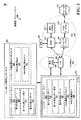
[0028]図1を参照すると、AG無線通信システム100は航空機104に対するブロードバンド接続性サービスのためのハンドオーバ管理を提供するように構成されたハンドオーバ管理コンポーネント102を含む態様を有して例示される。例えば、いくつかの態様において、ハンドオーバ管理コンポーネント102は、サービングAG基地局110からターゲットAG基地局112へのハンドオーバを管理するために航空機104内にインストールされたAirCard108内の複数のモデムと通信することができる。いくつかの態様において、ここで使用される「コンポーネント」という用語は、システムを構成するパーツのうちの1つであり得、またハードウェアまたはソフトウェアであり得、そして他のコンポーネントへ分割され得る。
[0028] Referring to FIG. 1, an AG wireless communication system 100 is illustrated with an aspect that includes a
[0029]いくつかの態様において、例えば、同一周波数バンド(例えば、衛星オペレーション)を使用する他のRATsにおける共存する通信への干渉を管理しながら、航空機104へのあるRATにおけるブロードバンド接続性を提供するために、サービングAG基地局110および/またはターゲットAG基地局112は航空機104の方向に向けて高いアンテナ利得を有する狭いペンシルビームを形成するために大型のアンテナアレイを用いるビームフォーミングを実行することができる。例えば、サービングAG基地局110はデータ送信を容易にするためにサービングビーム116を生成することができ、および、ハンドオーバ手続の後、ターゲットAG基地局112はデータ送信を容易にするためにターゲットビーム118を生成することができる。これらの態様において、例えば、航空機104はアンテナシステム114を含む、それは、複数のアンテナエレメントを用いるビームフォーミングを実行することができる。例えば、いくつかの態様において、アンテナシステム114はサービングAG基地局110と通信するためにモデム106により使用されるビーム117を生成することができる。これらの態様において、ハンドオーバ手続の間、ビーム117はターゲットAG基地局112への無線接続を確立するためにターゲットAG基地局112の方向へステアリングすることができる。
[0029] In some aspects, for example, providing broadband connectivity in one RAT to aircraft 104 while managing interference to coexistence communication in other RATs using the same frequency band (eg, satellite operations) In order to do so, the serving
[0030]いくつかの態様において、航空機104にインストールされたAirCard108は、ブロードバンド接続性帯域幅を提供するために異なるキャリア上で動作することができる任意の数のモデム106を含むことができる。いくつかの態様において、例えば、AirCard108の各モデム106は他のモデム106と独立して動作することができる。すなわち、AirCard108の異なる複数のモデム106は1以上のキャリア周波数上でサービングAG基地局110と独立して通信することができる。1つの限定しない例示態様において、AirCard108は5つのモデム106を含むことができ、各々は、ブロードバンド接続性のための20MHz帯域幅を提供する。したがって、そのような例示AirCard108は合計100MHzの帯域幅を提供することができる。いくつかの限定しない例示態様において、航空機104は2以上のAirCards108をインストールされることができる。しかしながら、これらの態様において、サービングAG基地局110は、航空機104の方へ方向づけられた1つのビーム、例えば、ビーム116を用いて複数の異なるAirCards108の異なる複数のモデム106をサービスすることができる。同様に、これらの態様において、航空機104のアンテナシステム114は、サービングAG基地局110へ方向づけられた1つのビーム、例えば、ビーム117を用いて異なる複数のAirCards108の複数の異なるモデム106にサービスすることができる。
[0030] In some aspects, the AirCard 108 installed on the aircraft 104 can include any number of
[0031]いくつかの態様において、例えば、ターゲットAG基地局112についての無線状態およびアドミッション制限(admission limits)における差異により、サービングAG基地局110からターゲットAG基地局112へのハンドオーバをトリガするために、航空機104上の異なるモデム106がハンドオーバ状態にあることができる。一般的に、複数の異なるモデム106の複数のハンドオーバ手続は異なる時間にトリガされることができ、それは、サービングAG基地局110のビームフォーミングコンポーネントが、サービングビーム116を提供することをいつ停止すべきかを決定することを困難にさせる可能性がある。同様に、複数の異なるモデム106のハンドオーバ手続が複数の異なる時間にトリガされると、ターゲットAG基地局112のビームフォーミングコンポーネントが、航空機104にサービスするためにターゲットビーム118を提供することをいつ開始するかを決定することが困難になる可能性がある。さらに、複数の異なるモデム106の複数のハンドオーバ手続きが複数の異なる時間にトリガされると、航空機104のアンテナシステム114のビームフォーミングコンポーネントがサービングAG基地局110からターゲットAG基地局112へいつビームをステアリングするかを決定することが困難である可能性がある。
[0031] In some aspects, for example, to trigger a handover from serving
[0032]しかしながら、いくつかの本態様によれば、AirCard104は上で示した懸案事項を解決するために、AirCard104の複数のモデム106に関する複数のハンドオーバ手続を管理するハンドオーバ管理コンポーネント102を含む。例えば、1つの態様において、ハンドオーバ管理コンポーネント102はサービングAG基地局110からターゲット基地局112へのすべてのモデム106のハンドオーバを同期させるために複数のモデム106と通信することができる。このため、ハンドオーバ手続の期間、航空機104のアンテナシステム112はビーム117をステアリングすることができる。それは、サービングAG基地局110からターゲットAG基地局112へ、サービングAG基地局110またはターゲット基地局112のそれぞれ1つと通信するためにすべてのモデム106により使用される。さらに、ハンドオーバ手続の後、サービングAG基地局110はビーム、たとえば、サービングビーム116を供給することを停止することができ、そしてその間に、ターゲットAG基地局112は航空機104内のモデム106にサービスするために新しい単一の狭いビーム、例えば、ターゲットビーム118を生成する。
However, according to some present aspects, the AirCard 104 includes a
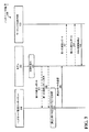
[0033]いくつかの本態様において、AG無線通信システム100は、図2を参照してここに例示されるように、ロングタームイボリューション(LTE)無線アクセス技術(RAT)に基づいて航空機104へブロードバンド接続性サービスを提供する。図2において、LTEネットワークアーキテクチャ200は、発展型パケットシステム(EPS)200と呼ばれることができるLTEネットワークアーキテクチャ200が例示される。EPS200は、航空機104(図示せず)にインストールされるAirCard108(図示せず)内の多数のモデム106のハンドオーバを管理するハンドオーバ管理コンポーネント102を含む。EPS200は、さらに、発展型UMTS地上無線アクセスネットワーク(E−UTRAN)204、発展型パケットコア(EPC)210、ホーム加入者サーバ(HSS)220、およびオペレータのIPサービス222を含み得る。EPSは、他の複数のアクセスネットワークと相互接続することができるが、簡潔化のために、それらのエンティティ/インターフェースは、示されていない。しかしながら、図示するように、EPSは、パケット交換サービスを提供するが、当業者が容易に理解するように、本開示全体を通じて提示される様々な概念は、回路交換サービスを提供する複数のネットワークに拡張され得る。さらに、この開示の態様は、LTEネットワークアーキテクチャに関して提示されるが、同じまたは類似の態様が他のタイプの複数のネットワークに拡張されることができる。
[0033] In some present aspects, the AG wireless communication system 100 may transmit to the aircraft 104 based on Long Term Evolution (LTE) Radio Access Technology (RAT), as illustrated herein with reference to FIG. Provide broadband connectivity services. In FIG. 2, LTE network architecture 200 is exemplified by LTE network architecture 200, which may be referred to as Evolved Packet System (EPS) 200. The EPS 200 includes a
[0034]E−UTRANはモデム106にサービスするサービングAG基地局110の例であり得る発展型ノードB(eNB)を含む。E−UTRANはまたモデム106のハンドオーバに関するターゲット基地局であり得るターゲットAG基地局112の例であり得る他の複数のeNBs208を含む。eNB206はモデム106に向けたユーザプレーンおよび制御プレーンプロトコルターミネーションを提供することができる。eNB206は、バックホール(例えば、X2インタフェース)を介して他の複数のeNBs208、例えば、ターゲットAG基地局112に接続されることができる。eNB206と他の複数のeNBs208はまた基地局、ベーストランシーバステーション、無線基地局、無線トランシーバ、トランシーバ機能、ベーシックサービスセット(BSS)、拡張サービスセット(ESS)、またはその他の適切な用語でも呼ばれることができる。eNB206は、モデム106のためにEPC210へのアクセスポイントを提供することができる。いくつかの態様において、例えば、モデム106の限定されない例は、セルラ電話、スマートフォン、セッション開始プロトコル(SIP)電話、ラップトップ、携帯情報端末(PDA)、衛星ラジオ、全地球測位システム、マルチメディアデバイス、映像デバイス、デジタルオーディオプレイヤ(例えば、MP3プレイヤ)、カメラ、ゲーム機器、または任意の他の同様の機能を有するデバイスを含む。モデム106はまた、当業者によって、移動局、加入者局、モバイルユニット、加入者ユニット、ワイヤレスユニット、遠隔ユニット、モバイルデバイス、ワイヤレスデバイス、ワイヤレス通信デバイス、遠隔デバイス、モバイル加入者局、ユーザ機器、モバイル端末、ワイヤレス端末、遠隔端末、ハンドセット、ユーザエージェント、モバイルクライアント、クライアント、または何らかの他の適切な用語で称され得る。
[0034] The E-UTRAN includes an evolved Node B (eNB), which may be an example of a serving
[0035]eNB206は、S1インターフェースによってEPC210に接続される。EPC210は、モビリティ管理エンティティ(MME)212、他のMMEs214、サービングゲートウェイ216、およびパケットデータネットワーク(PDN)ゲートウェイ218を含む。MME212は、モデム106とEPC210との間のシグナリングを処理する制御ノードである。一般に、MME212は、ベアラ(bearer)および接続管理を提供する。すべてのユーザIPパケットは、サービングゲートウェイ216を通じて転送されることができ、それ自体は、PDNゲートウェイ218に接続される。PDNゲートウェイ218は、UE IPアドレスの割り当て、ならびに他の機能を提供することができる。PDNゲートウェイ218は、オペレータのIPサービス222に接続される。オペレータのIPサービス222は、インターネット、イントラネット、IPマルチメディアサブシステム(IMS)、およびPSストリーミングサービス(PSS)を含み得る。
[0035] The
[0036]いくつかの態様において、モデム106は、第1の測定レポート232を決定するためにモデム106とeNB206および/または他のeNBs208との間の無線通信チャネルに関連した無線状態の測定を行うハンドオーバコンポーネント244を含むことができる。いくつかの態様において、例えば、AirCard108(図1参照)の幾つかのあるいはすべてのモデム106はそれぞれのモデム106により使用中のそれぞれの無線通信チャネルに関連した無線状態のそれぞれの測定を行う別個の複数のハンドオーバコンポーネント244を含む。
[0036] In some aspects,
[0037]次に、モデム106および/またはハンドオーバ244は第1の測定レポート232をハンドオーバ管理コンポーネント102に送信する。いくつかの代替あるいは追加の態様において、第1の測定レポート232をハンドオーバ管理コンポーネント102に送信する代わりにあるいはそれに加えて、モデム106および/またはハンドオーバコンポーネント244は、モデムがハンドオーバ状態にあることをそのような測定が示すとき、第1の測定レポート232を示す第1の測定レポート表示234をハンドオーバ管理コンポーネント102に送信することができる。ここに使用されるように、ハンドオーバ状態は、モデム106がeNB206から他の複数のeNBs208の1つへハンドオーバされる必要がある状態に言及する。例えば、いくつかの態様において、モデム106は第1の測定レポート232で報告されたサービングeNBとターゲットeNBの無線状態がそれぞれのハンドオーバトリガしきい値を満足するときハンドオーバ状態にある。いくつかの態様において、例えば、第1の測定レポート表示234はまた第1の測定レポート232を含むことができる。
Next, the
[0038]いくつかの態様において、ハンドオーバ管理コンポーネント102は、航空機104(図1参照)にインストールされたAirCard108(図1参照)の2以上のモデム106からそれぞれの第1測定レポート232および/または第1の測定レポート表示234を受信し記憶する。
[0038] In some aspects, the
[0039]次に、複数のモデム106から受信した複数の第1の測定レポート232および/または複数の第1の測定レポート表示234に基づいて、ハンドオーバ管理コンポーネント102および/またはハンドオーバ管理コンポーネント102のハンドオーバ決定コンポーネント230は、eNB206から他のeNB208へモデム106のハンドオーバをトリガするためにeNB206へ測定レポートをモデム106が送信すべきであると決定することができる。例えば、いくつかの態様において、複数の無線状態がそれぞれのハンドオーバトリガしきい値を満足する多数のモデム106(例えば、2以上のモデム106)があることを、モデム106から受信した第1の測定レポートおよび/または第1の測定レポート表示234が示すなら、ハンドオーバ管理コンポーネント102および/またはハンドオーバ決定コンポーネント230は、eNB206から他のeNB208、例えば、ターゲットeNBへのモデム106のハンドオーバをトリガするために各モデムが測定レポートをeNB206、例えば、サービングeNBへ送信すると決定することができる。
[0039] Next, based on the plurality of first measurement reports 232 and / or the plurality of first
[0040]次に、いくつかの態様において、例えば、ハンドオーバ管理コンポーネント102および/またはハンドオーバ決定コンポーネント230は、eNB206から他のeNB208へ航空機104(図1参照)のAirCard108(図1参照)の複数のモデム106のハンドオーバをトリガするためにすべてのモデム106が測定レポートをサービングeNB206へ送信することを示すメッセージを航空機104(図1参照)のAirCard108(図1参照)のすべてのモデム106に送信する。
[0040] Next, in some aspects, for example, the
[0041]いくつかの態様において、例えば、それぞれの第1の測定レポート232に対応する無線状態がそれぞれのハンドオーバトリガしきい値を満足するとき、ハンドオーバ管理コンポーネント102および/またはハンドオーバ決定コンポーネント230は、enB206にそれぞれの第1のレポート232を送信することを示す。
In some aspects, the
[0042]いくつかの代替態様において、例えば、それぞれのモデム106の第1の測定レポート232に対応する複数の無線状態がそれぞれのハンドオーバトリガしきい値を満足しないとき、eNB206から他のeNB208へそのようなモデム106のハンドオーバをトリガするために、ハンドオーバ管理コンポーネント102および/またはハンドオーバ決定コンポーネント230は、第1の測定レポート232とは異なる第2の測定レポート236を送信することをそのようなモデム106に示すことができる。言い換えれば、第2の測定レポート236はそれぞれのモデム106における無線状態を正確に反映することはできないかもしれないが、複数のモデム106(例えば、少なくとも1つのモデムがハンドオーバ状態を経験しているとき)によりハンドオーバの同期を達成するためにハンドオーバ管理コンポーネント102および/またはハンドオーバ決定コンポーネント230はそれぞれのモデム106に第2の測定レポート236を送信させることができる。
[0042] In some alternative aspects, for example, if multiple radio conditions corresponding to the
[0043]次に、第1の測定レポート232または第2の測定レポート236を受信すると、eNB206はLTE標準に規定されたハンドオーバ準備を実行する。例えば、いくつかの態様において、eNB206は無線リソース制御(RRC)接続再構成メッセージ246をそれぞれのモデム106に送信する。
[0043] Next, upon receiving the
[0044]次に、モデム106および/またはハンドオーバコンポーネント244は、RRC再構成メッセージ246の受信を示すために、RRC再構成表示240、例えば、アクノレジメント信号をハンドオーバ管理コンポーネント102に送信する。
[0044] Next, the
[0045]RRC再構成表示240に基づいて、ハンドオーバ管理コンポーネント102および/またはハンドオーバ手続開始コンポーネント238はそのモデム106に関するランダムアクセス手続きを開始することを決定する。例えば、いくつかの態様において、航空機104(図1参照)のAirCard104(図1参照)のモデム106からRRC再構成表示240を受信すると、ハンドオーバ管理コンポーネント102および/またはハンドオーバ手続開始コンポーネント238は、eNB206から他のeNB208へビーム117(図1参照)をステアリングすることをアンテナシステム114(図1参照)に通知し、次に、航空機(図1参照)のAirCard 104(図1参照)の複数のモデム106の各々にそれぞれのランダムアクセス手続きを開始させる。
[0045] Based on the
[0046]図3および4は、いくつかの本態様に従って、図1のAG無線通信システム100において、(または、いくつかの態様において、図2の発展型パケットシステム200内において)図1のサービングAG基地局110(またはいくつかの態様において、図2のeNB206)から図1のターゲットAG基地局112(または、いくつかの例示態様において図2の他の複数のeNBs208の1つ)へのモデム106のハンドオーバのための例示ハンドオーバ手続を例示する。
[0046] Figures 3 and 4 illustrate the serving of Figure 1 in the AG wireless communication system 100 of Figure 1 (or in some aspects, the evolved packet system 200 of Figure 2) according to some present aspects A modem from the AG base station 110 (or in some aspects, the
[0047]図3を参照すると、ハンドオーバ手続300において、モデム106はモデム106とサービングAG基地局110および/またはターゲットAG基地局112との間の無線通信チャネルに関連した無線状態の測定302を実行する。いくつかの態様において、例えば、AirCard108(図1参照)のいくつかのまたはすべてのモデム106はそれぞれの無線通信チャネルに関連した無線状態のそれぞれの測定を実行する。
[0047] Referring to FIG. 3, in the handover procedure 300, the
[0048]次に、モデム106は実行された測定302の第1の測定レポート304をハンドオーバ管理コンポーネント102に送信する。いくつかの代替または追加の態様において、モデム106は実行された測定302の第1の測定レポート表示306をハンドオーバ管理コンポーネント102に送信することができる。例えば、いくつかの態様において、モデム106がハンドオーバ状態にある、すなわち、モデム106がサービングAG基地局110からターゲットAG基地局112へハンドオーバされる必要があることをそのような測定が示すとき、モデム106は、実行された測定302の第1の測定レポート表示306をハンドオーバ管理コンポーネント102に送信することができる。例えば、いくつかの態様において、第1の測定レポート304におけるサービングAG基地局110とターゲットAG基地局112の無線状態がそれぞれのハンドオーバトリガしきい値を満足するとき、モデム106はハンドオーバ状態にある。いくつかの態様において、例えば、第1の測定レポート表示306はまた、実行された測定302の第1の測定レポート304を含むことができる。
[0048] Next, the
[0049]いくつかの態様において、ハンドオーバ管理コンポーネント102は航空機104(図1参照)のAirCard108の2以上のモデム106からそれぞれの第1の測定レポート304および/または第1の測定レポート表示306を受信し記憶する。
[0049] In some aspects,
[0050]次に、ブロック308において、複数のモデム106から受信された複数の第1の測定レポート304および/または複数の第1の測定レポート表示306に基づいて、モデム106はサービングAG基地局110からターゲットAG基地局112へモデム106のハンドオーバをトリガするためにサービングAG基地局110へ測定レポートを送信すべきであることをハンドオーバ管理コンポーネント102が決定することができる。例えば、いくつかの態様において、ブロック308において、(第1の測定レポート304および/または第1の測定レポート表示306により示される)無線状態がそれぞれのハンドオーバトリガしきい値を満足する多数のモデム106(例えば、2以上のモデム106)があることを、複数のモデム106から受信された第1の測定レポート304および/または第1の測定レポート表示306が示す場合、サービングAG基地局110からターゲットAG基地局112へモデム106のハンドオーバをトリガするためにサービングAG基地局110へ測定レポートを各モデム106が送信することをハンドオーバ管理コンポーネント102は決定することができる。
[0050] Next, at block 308, based on the plurality of first measurement reports 304 and / or the plurality of first measurement report indications 306 received from the plurality of
[0051]例えば、いくつかの態様において、ブロック308において、無線状態がそれぞれのハンドオーバトリガしきい値を満足するモデム106の数がハンドオーバ準備(preparation)トリガしきい値を超えることを、複数のモデム106から受信された複数の第1の測定レポート304および/または複数の第1の測定レポート表示306が示すなら、サービングAG基地局110からターゲットAG基地局112へのモデム106のハンドオーバをトリガするために各モデム106は、測定レポートをサービングAG基地局110へ送信することをハンドオーバ管理コンポーネント102はブロック308において決定することができる。
[0051] For example, in some aspects, at block 308, the plurality of modems may have the number of
[0052]いくつかの態様において、たとえばブロック308において、サービングAG基地局110からターゲットAG基地局112へモデム106のハンドオーバをトリガするためにサービングAG基地局110へ測定レポートを複数のモデム106が送信することをハンドオーバ管理コンポーネント102が決定すると、サービングAG基地局110からターゲットAG基地局112へ航空機104(図1参照)のAirCard108(図1参照)の複数のモデム106のハンドオーバをトリガするためにサービングAG基地局110へ測定レポートを複数のモデム106が送信することを示すメッセージ310を航空機104(図1参照)のAirCard108(図1参照)の複数のモデム106へハンドオーバ管理コンポーネント102が送信する。
[0052] In some aspects, for example, at block 308, the plurality of
[0053]たとえば、いくつかの態様において、それぞれの第1の測定レポート304に対応する複数の無線状態がそれぞれのハンドオーバトリガしきい値を満足するとき、サービングAG基地局110へそれぞれの第1の測定レポートを含むメッセージ312を送信することをメッセージ310はモデム106に示すことができる。
For example, in some aspects, when a plurality of radio conditions corresponding to respective first measurement reports 304 satisfy respective handover trigger thresholds, respective first serving state to serving
[0054]いくつかの代替態様において、たとえば、モデム106の第1の測定レポートに対応する無線状態がそれぞれのハンドオーバトリガしきい値を満足しないけれどもいくつかのモデム106はハンドオーバ状態を経験するとき、サービングAG基地局110からターゲットAG基地局112へのそのようなモデム106のハンドオーバをトリガするためにサービングAG基地局110へ、第1の測定レポートとは異なる第2の測定レポートを含むメッセージ314をそのようなモデム106が送信することを示すためのメッセージ310をハンドオーバ管理コンポーネント102がそのようなモデム106へ送信する。いくつかの態様において、たとえば、第2測定レポートの値は対応するハンドオーバトリガしきい値を満足する(AirCard108の)他のモデム106からの測定レポートの値であり得る。すなわち、第1の測定レポートに基づいて、そのようなモデム106の無線状態はそれぞれのハンドオーバトリガしきい値を満足しないので、そのような第1の測定レポートをサービングAG基地局110へ送信することはそのようなモデム106のハンドオーバをトリガしないであろう。したがって、そのようなモデム106のハンドオーバをトリガするために、ハンドオーバ管理コンポーネント102は、そのようなモデム106がサービングAG基地局110からターゲットAG基地局112へハンドオーバをトリガするために第1の測定レポートとは異なる第2の測定レポートを含むメッセージ314をそのようなモデム106が送信することを示すメッセージ310を、ハンドオーバ管理コンポーネント102がそのようなモデム106へ送信する。したがって、そのような第2の測定レポートは、そのようなモデム106の真の無線状態を示すことができないかもしれない、例えば、そのようなモデム106の偽の測定レポートである可能性がある。
[0054] In some alternative aspects, for example, when the radio conditions corresponding to the first measurement report of
[0055]したがって、いくつかの本態様において、モデム106は、モデム106がハンドオーバ管理測定コンポーネント102からメッセージ310を受信しないかぎり、サービングAG基地局110へ測定レポートを送信しない。
Thus, in some of the present aspects, the
[0056]それぞれの第1の測定レポートを含むメッセージ312またはそれぞれの第2の測定レポートを含むメッセージ314をモデム106から受信すると、サービングAG基地局110はたとえば、LTE標準に定義されるハンドオーバ準備を実行する。たとえば、いくつかの態様において、それぞれの第1の測定レポートを含むメッセージ312またはそれぞれの第2の測定レポートを含むメッセージ314を受信すると、サービングAG基地局110は無線リソース制御(RRC)接続再構成メッセージ316をそれぞれのモデム106へ送信する。
[0056] Upon receiving from the modem 106 a message 312 comprising a respective first measurement report or a
[0057]図4を参照すると、ハンドオーバ手続400のさらなる態様がモデム106による、サービングAG基地局110(図3参照)からRRC接続再構成メッセージの受信に続くハンドオーバ手続のさらなる態様が例示される。サービングAG基地局110(図3参照)からRRC接続再構成メッセージ316(図3参照)を受信すると、モデム106はそのようなメッセージの受信を示すメッセージ402をハンドオーバ管理コンポーネント102へ送信する。
[0057] Referring to FIG. 4, further aspects of the handover procedure are illustrated, following the receipt of the RRC connection reconfiguration message by the
[0058]ブロック404において、受信メッセージ402に基づいて、ハンドオーバ管理コンポーネント102は、モデム106がランダムアクセス手続を開始することを決定する。たとえば、いくつかの態様において、航空機104(図1参照)のAirCard104(図1参照)のモデム106からメッセージ402を受信すると、それぞれのRRC接続再構成を示すために、ハンドオーバ管理コンポーネント102はタイマを開始し、航空機104の(図1参照)のAirCard104(図1参照)の他のモデム106がそれぞれのメッセージ402を送信するのを待つ。これらの態様において、およびさらにブロック404を参照して、航空機104(図1参照)のAirCar104(図1参照)の他のモデム106の各々からそれぞれのメッセージ402を受信すると、あるいは、代替的に、タイマ満了時に、ハンドオーバ管理コンポーネント102は、航空機104(図1参照)のAirCard104(図1参照)のモデム106の各々がそれぞれのランダムアクセス手続を開始することを決定する。
[0058] At
[0059]したがって、ハンドオーバ管理コンポーネント102は、それぞれのランダムアクセス手続きを開始することをモデム106に示すためのメッセージ406を航空機104(図1参照)のAirCard104(図1参照)の各モデム106へ送信する。
Thus, the
[0060]メッセージ406を受信すると、各モデム106は、LTE標準で定義されたランダムアクセス手続き408とRRC接続セットアップ手続き410を実行するために各モデム106はターゲットAG基地局112と通信する。
[0060] Upon receiving the message 406, each
[0061]いくつかの態様において、ハンドオーバ手続300、400を実行する際に、サービングAG基地局110とターゲットAG基地局112はハンドオーバ管理コンポーネント102の存在および/または実行により影響されないかもしれない。すなわち、ハンドオーバ手続300、400に適応するために、サービングAG基地局110および/またはターゲットAG基地局112は、ランダムアクセス手続きおよび/またはRRC接続セットアップ手続きを実行するために適用可能な一般的標準(たとえば、適用可能なLTE標準)における任意の変化を必要としない。
[0061] In some aspects, in performing the handover procedure 300, 400, the serving
[0062]したがって、いくつかの態様において、航空機上の複数のモデムのハンドオーバを同期させることにより、航空機のアンテナシステムは、いつでも航空機内のすべてのモデムにサービスするために単一の地上基地局へ向けて単一のビームを供給することができ、単一の地上基地局はいつでも航空機内のすべてのモデムにサービスするために航空機へ向けて1つのビームを供給することができる。 [0062] Thus, in some aspects, by synchronizing the handover of multiple modems on the aircraft, the antenna system of the aircraft can always go to a single ground base station to service all the modems in the aircraft. A single beam can be provided to direct, and a single ground base station can always provide one beam to the aircraft to service all modems in the aircraft.
[0063]図5乃至9は、図1のAG無線通信システム100の一例であり得る図2のネットワークアーキテクチャの態様において、それぞれの方法500、600、700、800、および900を記載する。例えば、方法500、600、700、800および900は、サービングAG基地局110からターゲットAG基地局112へ航空機104にインストールされたAirCard108の複数のモデム106のハンドオーバ手続を管理するためにここに記載されたハンドオーバ管理コンポーネント102(図1および2)により実行されることができる。この場合、方法500はサービング基地局からターゲット基地局への2以上のモデムのハンドオーバ管理手続きの1つの態様に関連し、方法600は、少なくとも1つのメッセージに基づいて、サービング基地局からターゲット基地局へ2以上のモデムをハンドオーバするかどうかを決定する1つの態様に関連し、方法700は、それぞれのハンドオーバ手続をトリガするように構成された測定レポートをサービング基地局へ送信することを2以上のモデムの各々へ示す態様に関連し、方法800は、2以上のモデム内の少なくとも1つのモデムからの無線状態を示す少なくとも1つのメッセージを受信する態様に関連し、および方法900はサービング基地局からターゲット基地局へ2以上のモデムのハンドオーバ手続を開始するかどうかを決定する態様に関連する。
[0063] FIGS. 5-9 describe
[0064]図5を参照すると、ブロック502において、サービング基地局からターゲット基地局への2以上のモデムのハンドオーバ手続を管理する方法の1つの態様において、方法500は2以上のモデムの少なくとも1つのモデムからの無線状態の少なくとも1つの測定レポートを示す少なくとも1つのメッセージを受信することを含む。たとえば、いくつかの態様において、ハンドオーバ管理コンポーネント102は、航空機104内にインストールされたAirCard108の2以上のモデム106内の少なくとも1つのモデム106から無線状態の少なくとも1つの測定レポート(例えば、第1の測定レポート232)を示す少なくとも1つのメッセージを受信することができる。
[0064] Referring to FIG. 5, in
[0065]ブロック504において、方法500は、サービング基地局からターゲット基地局へ2以上のモデムをハンドオーバするかどうかを少なくとも1つのメッセージに基づいて決定することを含む。たとえば、いくつかの態様において、ハンドオーバ管理コンポーネント102および/またはハンドオーバ決定コンポーネント230は、サービングAG基地局110(それは図2のeNB206であり得る)からターゲットAG基地局112(それは図2内の他のeNBs208の1つであり得る)へ2以上のモデム106をハンドオーバするかどうかを、複数のモデム106から受信された少なくとも1つのメッセージに基づいて、決定することができる。
[0065] At
[0066]ブロック506において、方法500は、サービング基地局からターゲット基地局へ2以上のモデムをハンドオーバすることを決定すると、サービング基地局からターゲット基地局へそれぞれのハンドオーバ手続をトリガするように構成された測定レポートをサービング基地局へ送信することを2以上のモデムの各々へ示すことを含む。たとえば、いくつかの態様において、サービングAG基地局110からターゲットAG基地局112へ航空機104のAirCard108の2以上のモデム106をハンド―オーバすることをハンドオーバ管理コンポーネント102および/またはハンドオーバ決定コンポーネント230により決定すると、ハンドオーバ管理コンポーネント102は、サービングAG基地局110からターゲットAG基地局112へそれぞれのハンドオーバ手続をトリガするように構成された測定レポートをサービングAG基地局110へ送信することを2以上のモデム106の各々へ示すことができる。
[0066] At
[0067]任意的に、ブロック508において、方法500は、第1のモデムが測定レポートをサービング基地局へ送信することに応答してサービング基地局から無線リソース制御(RRC)再構成メッセージを第1のモデムが受信したことを示す信号を、2以上のモデムの第1のモデムから受信することを含む。たとえば、1つの態様において、ハンドオーバ管理コンポーネントは、第1の測定レポート232または第2の測定レポート236のそれぞれの1つをモデム106がサービングAG基地局110へ送信することに応答してサービングAG基地局110からRRC再構成メッセージ246をモデム106が受信したことを示す信号、たとえばRRC再構成表示240をモデム106から受信することができる。
[0067] Optionally, at
[0068]任意的に、ブロック510において、方法500はサービング基地局からターゲット基地局へ2以上のモデムのハンドオーバ手続を開始するかどうかをその信号に基づいて決定することを含む。たとえば、1つの態様において、ハンドオーバ管理コンポーネント102および/またはハンドオーバ手続開始コンポーネント238は、サービングAG基地局110からターゲットAG基地局112への2以上のモデム106のハンドオーバ手続を開始するかどうかを、RRC再構成表示240に基づいて決定することができる。
[0068] Optionally, at
[0069]任意的に、ブロック512において方法500は、サービング基地局からターゲット基地局へ2以上のモデムのハンドオーバ手続を開始することを決定すると、サービング基地局からターゲット基地局へそれぞれのハンドオーバ手続を実行することを開始することを2以上のモデムの各々へ示すことを含む。たとえば、1つの態様において、ハンドオーバ管理コンポーネント102および/またはハンドオーバ手続開始コンポーネント238が、サービングAG基地局110からターゲットAG基地局112への航空機104のAirCard108の2以上のモデム106のハンドオーバ手続を開始することを決定すると、ハンドオーバ管理コンポーネント102はサービングAG基地局110からターゲットAG基地局112へのそれぞれのハンドオーバ手続の実行を開始することを航空機104のAirCard108の2以上のモデム106の各々に示すことができる。
[0069] Optionally, at
[0070]任意的に、ブロック514において、方法500は、2以上のモデムが航空機内に配置されているとき、サービング基地局からターゲット基地局へ2以上のモデムのハンドオーバ手続を開始することを決定すると、サービング基地局からターゲット基地局へビームをステアリングすることを航空機のアンテナシステムに通知することを含む。たとえば、1つの態様において、2以上のモデム106が航空機104内に配置されると、サービングAG基地局110からターゲットAG基地局112へ、航空機104のAirCard108の2以上のモデム106のハンドオーバ手続を開始することをハンドオーバ管理コンポーネント102および/またはハンドオーバ手続開始コンポーネント238が決定すると、ハンドオーバ管理コンポーネント102は、サービングAG基地局110からターゲットAG基地局112へビーム117をステアリングするように航空機104のアンテナシステム114へ通知することができる。
[0070] Optionally, at
[0071]図6を参照すると、方法600は、サービング基地局からターゲット基地局へ2以上のモデムをハンドオーバするかどうかを少なくとも1つのメッセージに基づいて決定するための、図5のブロック504の例示および任意の態様を提供する。
[0071] Referring to FIG. 6, the
[0072]ブロック602において、方法600は2以上のモデム内の多数のモデムがハンドオーバ状態にあることを少なくとも1つのメッセージに基づいて決定することを含む。たとえば、1つの態様において、ハンドオーバ管理コンポーネント102および/またはハンドオーバ決定コンポーネント230は、航空機104のAirCard108の多数のモデム106がハンドオーバ状態にあることを、複数のモデム106から受信された少なくとも1つのメッセージに基づいて、決定することができる。
[0072] At
[0073]ブロック604において、方法600は、モデムの数がしきい値を超えると、サービング基地局からターゲット基地局へ2以上のモデムをハンドオーバすることを決定することを含む。たとえば、1つの態様において、ハンドオーバ状態にあるモデムの数がしきい値を超えると、サービングAG基地局110からターゲットAG基地局112へ航空機104のAirCard108の複数のモデムをハンドオーバすることをハンドオーバ管理コンポーネント102および/またはハンドオーバ決定コンポーネント230は決定することができる。1つの例示態様において、そのようなしきい値はたとえば、航空機104のAirCard108の2つのモデム106であり得る。
[0073] At
[0074]図7を参照すると、方法700は、それぞれのハンドオーバ手続をトリガするように構成された測定レポートをサービング基地局へ送信することを2以上のモデムの各々へ示すための、図5のブロック506の1つの例示および任意の態様を提供する。
[0074] Referring to FIG. 7, the
[0075]ブロック702において、方法700は、モデムがハンドオーバ状態にあることをモデムの第1の測定レポート232が示すとき、第1の測定レポートをサービング基地局へ送信することをモデムに示すことを含む。たとえば、1つの態様において、モデム106がハンドオーバ状態にあることをモデム106の第1の測定レポート232が示すとき、ハンドオーバ管理コンポーネント102および/またはハンドオーバ決定コンポーネント230は、第1の測定レポート232をサービングAG基地局110へ送信することをモデム106へ示すことができる。
[0075] At
[0076]ブロック704において、方法700は、モデムがハンドオーバ状態にないことをモデムの第1の測定レポートが示すとき、第2の測定レポートをサービング基地局へ送信することをモデムに示すことを含む。この場合、第2の測定レポートはサービング基地局からターゲット基地局へモデムのハンドオーバ手続をトリガするように構成される。たとえば、1つの態様において、モデム106がハンドオーバ状態にないことをモデム106の第1の測定レポートが232が示すとき、ハンドオーバ管理コンポーネント102および/またはハンドオーバ決定コンポーネント230は第2の測定レポート236をサービングAG基地局110へ送信することをモデム106に示すことができる。この場合、第2の測定レポート236はサ-ビングAG基地局110からターゲットAG基地局112へモデム106のハンドオーバ手続をトリガするように構成される。
[0076] At
[0077]任意のブロック706において、方法700は、第2の測定をモデムに送信することを含む。たとえば、1つの態様において、モデム106がハンドオーバ状態にないことをモデム106の第1の測定レポート232が示すとき、サービングAG基地局110からターゲットAG基地局112へモデムのハンドオーバ手続をトリガするためにモデム106が第2の測定レポート236をサービングAG基地局110へ送信することができるように、第2の測定レポート236をモデム106へ送信することができる。
[0077] At
[0078]図8を参照すると、方法800は、少なくとも1つの測定レポートを示す少なくとも1つのメッセージの受信に関する図5のブロック502の1つの例示および任意の態様を提供する。
[0078] Referring to FIG. 8,
[0079]任意のブロック802において、方法800はモデムから第1の測定レポートを受信することを含む。たとえば、1つの態様において、ハンドオーバ管理コンポーネント102はモデム106から第1の測定レポート232を受信することができる。
[0079] At
[0080]任意のブロック804において、方法800はモデムがハンドオーバ状態にあるという表示を受信する。たとえば、1つの態様において、モデム106がハンドオーバ状態にあることを第1の測定レポート232が示すとき、ハンドオーバ管理コンポーネント102は、モデム106がハンドオーバ状態にあるという表示を受信することができる。たとえば、1つの態様において、ハンドオーバ管理コンポーネント102は、モデム106がハンドオーバ状態にあることを示す第1の測定レポート表示234をモデム106から受信することができる。
[0080] At
[0081]図9を参照すると、サービング基地局からターゲット基地局へ2以上のモデムのハンドオーバ手続きを開始するかどうかを信号に基づいて決定するための、図5のブロック510の1つの例示かつ任意の態様を提供する。
[0081] Referring to FIG. 9, one exemplary and optional one of
[0082]ブロック902において、方法900は信号を受信するとタイマを開始することを含む。たとえば、1つの態様において、RRC再構成表示240を受信すると、ハンドオーバ管理コンポーネント102および/またはハンドオーバ手続き開始コンポーネント238はRRC再構成開始タイマ242を開始することができる。
[0082] At
[0083]ブロック904において、方法900は、それぞれの測定レポートをサービング基地局へ送信することに応答してサービング基地局からそれぞれのRRC再構成メッセージを各モデムが受信したことを示すアクノレジメント信号を2以上のモデム内の各モデムから受信するとまたはタイマが満了すると、サービング基地局からターゲット基地局へ2以上のモデムのハンドオーバ手続を開始することを決定することを含む。たとえば、1つの態様において、RRC再構成開始タイマ242の満了時あるいはサービングAG基地局110へそれぞれの第1の測定レポート232または第2の測定レポート236を送信することに応答してサービングAG基地局110からそれぞれのRRC再構成メッセージ246を、航空機104のAirCard18の各モデム106が受信したことを示すRRC再構成表示240を受信すると、ハンドーバ管理コンポーネント102および/またはハンドオーバ手続開始コンポーネント238は、サービングAG基地局110からターゲットAG基地局112へ航空機104のAirCard108の2以上のモデム106のハンドオーバ手続を開始することを決定することができる。いくつかの態様において、たとえば、各ハンドオーバ手続はランダムアクセス手続およびRRC接続セットアップ手続きを含む。
[0083] At
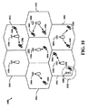
[0084]図10を参照すると、LTEネットワークアーキテクチャの一部であり得るアクセスネットワーク1000の一例が例示される。アクセスネットワーク500は図1のハンドオーバ管理コンポーネント102と通信する図1のモデム106の一例であり得るUEs506を含む。UEs1006は図1のモデム106に関してここに記載される任意の機能を実行するように構成されることができる。また、アクセスネットワーク1000は図2のeNB206と208であり得るeNBs1004とeNB1008を含む。
[0084] Referring to FIG. 10, an
[0085]この例において、アクセスネットワーク1000は多数のセルラ領域(セル群)1002に分割される。1つまたは複数の低電力クラスeNBs1008はセル群1002の1つまたは複数とオーバラップするセルラ領域1010を有することができる。低電力クラスeNB1008はスモールセル(たとえば、フェムトセル(たとえば、ホームeNB(HeNB))、ピコセル、マイクロセル、またはリモートラジオヘッド(RRH)であり得る。マクロeNBs1004は各々、それぞれのセル1002に割り当てられ、セル1002中の全てのUEs1006に対してEPC110へのアクセスポイントを提供するように構成される。アクセスネットワーク1000のこの例では集中制御装置(centralized controller)は存在しないが、代替の構成では、集中制御装置が使用され得る。eNBs1004は、無線ベアラ制御、アドミッション制御、モビリティ制御、スケジューリング、セキュリティ、およびサービングゲートウェイ216への接続性を含む、すべての無線に関連する機能を担う。
[0085] In this example,
[0086]アクセスネットワーク1000によって用いられる変調および多元接続スキームは、展開されている特定の電気通信標準に依存して異なり得る。LTEアプリケーションにおいては、周波数分割複信(FDD)および時分割複信(TDD)の両方をサポートするために、OFDMがDL上で使用され、SC−FDMAがUL上で使用される。以下の詳細な説明から当業者が容易に理解するように、本明細書に提示される様々な概念は、LTEアプリケーションによく適する。しかしながら、これらの概念は、他の変調および多元接続技法を用いる他の電気通信規格に容易に拡張され得る。例として、これらの概念は、エボリューションデータオプティマイズド(Evolution-Data Optimized)(EV−DO)またはウルトラモバイルブロードバンド(UMB)に拡張され得る。EV−DOおよびUMBは、CDMA2000ファミリー標準の一部として、3世代パートナーシッププロジェクト2(3GPP2)によって公表されたインターフェース標準であり、モバイル局にブロードバンドインターネットアクセスを提供するためにCDMAを用いる。これらの概念はまた、広帯域CDMA(W−CDMA(登録商標))、およびTD−SCDMAのようなCDMAの他の変形例を用いるユニバーサル地上無線アクセス(UTRA)、TDMAを用いる移動体通信のためのグローバルシステム(GSM(登録商標))、およびOFDMAを用いるフラッシュOFDM、IEEE802.20、IEEE802.16(WiMAX)、IEEE802.11(Wi−Fi)、および発展型UTRA(E−UTRA)に拡張されることができる。UTRA、E−UTRA、UMTS、LTE、およびGSMは、3GPPの組織からの文書中で説明されている。CDMA2000およびUMBは、3GPP2の組織からの文書中で説明されている。用いられる実際のワイヤレス通信規格および多元接続技術は、システム上に課せられる全体的な設計制約および特定のアプリケーションに依存するであろう。
The modulation and multiple access schemes used by
[0087]eNBs1004は、MIMO技術をサポートする複数のアンテナを有することができる。MIMO技術の使用は、eNBs1004が、空間多重、ビームフォーミング、および送信ダイバーシティをサポートするために空間領域を利用することを可能にする。空間多重化は、同じ周波数上で同時にデータの異なるストリームを送信するために使用されることができる。それらのデータストリームは、データレートを増すために単一のUE1006に、または、全システム容量を増加させるために複数のUE1006に、送信されることができる。これは、各データストリームを空間的にプリコードし(すなわち、振幅および位相のスケーリングを適用し)、その後、DL上の複数の送信アンテナを通じて各々の空間的にプリコードされたストリームを送信することによって達成される。空間的にプリコードされたデータストリームは、異なる空間シグネチャとともにUE(s)1006へ到達し、それは、UE(s)1006の各々が、そのUE1006を宛先とする1つ以上のデータストリームをリカバ(recover)することを可能にする。UL上では、それぞれのUE1006は、空間的にプリコードされたデータストリームを送信し、それは、eNB1004が、それぞれの空間的にプリコードされたデータストリームのソースを識別することを可能にする。
[0087] eNBs 1004 may have multiple antennas supporting MIMO technology. The use of MIMO technology enables
[0088]空間多重化は一般に、チャネル条件が良好なときに使用される。チャネル条件があまり良好でないとき、1つまたは複数の方向に送信エネルギーを集中させるためにビームフォーミングが使用され得る。これは、複数のアンテナを通じた送信のためにデータを空間的にプリコードすることによって達成され得る。セルの端において良好なカバレッジを達成するために、単一ストリームのビームフォーミング送信は、送信ダイバーシティと組み合わせて使用されることができる。 [0088] Spatial multiplexing is generally used when channel conditions are good. Beamforming may be used to focus transmit energy in one or more directions when channel conditions are not very good. This may be achieved by spatially precoding data for transmission through multiple antennas. In order to achieve good coverage at the end of the cell, single stream beamforming transmission can be used in combination with transmit diversity.
[0089]次の詳細な説明において、アクセスネットワークの様々な態様は、DL上でOFDMをサポートするMIMOシステムに関連して説明される。OFDMは、OFDMシンボル内の多数のサブキャリアにわたってデータを変調する拡散スペクトル技術である。サブキャリアは、正確な周波数で間隔が空けられている。間隔を空けること(spacing)は、受信機がサブキャリアからのデータをリカバすることを可能にする「直交性(orthogonality)」を提供する。時間領域では、OFDMシンボル間干渉に対抗するために、各OFDMシンボルにガードインターバル(例えば、サイクリックプリフィックス)が付加され得る。ULは、高いピーク対平均電力比(PAPR)を補償するために、DFT拡散されたOFDM信号の形態でSC−FDMAを使用することができる。 [0089] In the following detailed description, various aspects of the access network are described in connection with a MIMO system that supports OFDM over DL. OFDM is a spread spectrum technique that modulates data across multiple subcarriers in an OFDM symbol. The subcarriers are spaced at the correct frequency. Spacing provides "orthogonality" which allows the receiver to recover data from the subcarriers. In the time domain, guard intervals (eg, cyclic prefixes) may be added to each OFDM symbol to combat OFDM inter-symbol interference. The UL can use SC-FDMA in the form of a DFT-spread OFDM signal to compensate for high peak to average power ratio (PAPR).
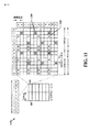
[0090]図11はLTEにおけるDLフレーム構造および図2に示されるLTEネットワークアーキテクチャのようなLTEネットワークアーキテクチャにおけるFDおよびHD通信において使用され得るLTEのDLフレーム構造の一例を例示する図1100である。フレーム(10ms)は、10の等しいサイズのサブフレームに分割され得る。各サブフレームは、2つの連続するタイムスロットを含むことができる。リソースグリッドは、2つのタイムスロットを表すために使用されることができ、各タイムスロットは、リソースブロックを含む。リソースグリッドは、複数のリソース要素に分割される。LTEにおいて、リソースブロックは、周波数領域に12の連続するサブキャリアを、および各OFDMシンボル内通常のサイクリックプリフィックスに関して、時間領域に7つの連続するOFDMシンボルを、すなわち、84のリソース要素を含む。拡張されたサイクリックプリフィックスに関して、リソースブロックは、時間領域に6つの連続するOFDMシンボルを含み、72のリソース要素を有する。R1102、1104として示されるリソース要素のうちのいくつかは、DL基準信号(DL−RS)を含む。DL−RSは、セル固有RS(CRS)(共通RSと呼ばれることもある)1102およびUE固有RS(UE−RS)1104を含む。UE−RS1104は、対応する物理DL共有チャネル(PDSCH)がマッピングされるリソースブロック上でのみ送信される。各リソース要素によって搬送されるビット数は、変調スキームに依存する。従って、UE(たとえば、図1および2のモデム106)が受信するリソースブロックがより多いほど、および変調スキームがより高度であるほど、UEに関するデータレートはより高くなる。
[0090] FIG. 11 is a diagram 1100 illustrating an example of an LTE DL frame structure that may be used in FD and HD communications in an LTE network architecture such as the DL frame structure in LTE and the LTE network architecture shown in FIG. The frame (10 ms) may be divided into 10 equally sized sub-frames. Each subframe may include two consecutive time slots. A resource grid can be used to represent two time slots, each time slot containing a resource block. A resource grid is divided into a plurality of resource elements. In LTE, a resource block includes 12 consecutive subcarriers in the frequency domain and 7 consecutive OFDM symbols in the time domain, ie, 84 resource elements, for a normal cyclic prefix in each OFDM symbol. For the expanded cyclic prefix, the resource block includes 6 consecutive OFDM symbols in the time domain and has 72 resource elements. Some of the resource elements shown as
[0091]図12はLTEにおけるULフレーム構造の一例であり、図2に示されるLTEネットワークアーキテクチャのようなLTEネットワークアーキテクチャにおけるFDおよびHD通信において使用され得るLTEにおけるULフレーム構造の一例を例示する図1200である。ULに関する利用可能なリソースブロックは、データセクションと制御セクションとに区分され得る。制御セクションは、システム帯域幅の2つの端で形成されることができ、設定可能なサイズを有し得る。制御セクション中のリソースブロックは、制御情報の送信のためにUE(例えば、図1および2のモデム106)に割り当てられ得る。データセクションは、制御セクション中に含まれない全てのリソースブロックを含むことができる。ULフレーム構造は、連続するサブキャリアを含むデータセクションを生じ、それは、単一のUEが、データセクション中の連続するサブキャリアの全てに割り当てられることを可能にすることができる。
[0091] FIG. 12 is an example of a UL frame structure in LTE, illustrating an example of a UL frame structure in LTE that may be used in FD and HD communications in an LTE network architecture such as the LTE network architecture shown in FIG. It is 1200. Available resource blocks for UL may be divided into data section and control section. The control section can be formed at the two ends of the system bandwidth and can have a configurable size. Resource blocks in the control section may be assigned to a UE (eg,
[0092]UEは、eNB(たとえば、図2のeNB206および208)に制御情報を送信するために制御セクション中のリソースブロック1210a、710bに割り当てられることができる。UEはまた、eNBにデータを送信するためにデータセクション中のリソースブロック1220a、1220bに割り当てられることができる。UEは、制御セクション中の割り当てられたリソースブロック上の物理UL制御チャネル(PUCCH)で制御情報を送信することができる。UEは、データセクション中の割り当てられたリソースブロック上の物理UL共有チャネル(PUSCH)中でデータのみ、またはデータと制御情報の両方を送信することができる。UL送信は、サブフレームの両方のスロットにわたり、周波数を横断してホッピングすることができる。
[0092] A UE may be assigned to
[0093]リソースブロックのセットは、物理ランダムアクセスチャネル(PRACH)1230で、初期システムアクセスを遂行し、UL同期を達成するために使用されることができる。PRACH 1230は、ランダムシーケンスを搬送し、いずれのULデータ/シグナリングも搬送することはできない。各ランダムアクセスプリアンブルは、6つの連続したリソースブロックに対応する帯域幅を占有する。開始周波数は、ネットワークによって指定される。すなわち、ランダムアクセスプリアンブルの送信は、ある時間および周波数リソースに制限される。PRACHに関する周波数ホッピングは存在しない。PRACH試行は、単一のサブフレーム(1ms)で、または少数の連続するサブフレームのシーケンスで搬送され、UEは、フレーム(10ms)あたり1つのPRACH試行のみを行うことができる。
[0093] A set of resource blocks may be used to perform initial system access and to achieve UL synchronization on a physical random access channel (PRACH) 1230. The
[0094]図13は、LTEにおけるユーザおよび制御プレーンに関する無線プロトコルアーキテクチャであって図2に示されるようなLTEネットワークアーキテクチャにおけるFDおよびHD通信において使用され得る無線プロトコルアーキテクチャの一例を例示する。UEとeNB(たとえば、図2のモデム106およびeNB206または208)に関する無線プロトコルアーキテクチャは3つのレイヤ:レイヤ1、レイヤ2およびレイヤ3で表示される。レイヤ1(L1レイヤ)は、最下位のレイヤであり、様々な物理レイヤ信号処理機能をインプリメントする。L1レイヤは、本明細書では物理レイヤ1306と呼ばれる。レイヤ2(L2レイヤ)1308は、物理レイヤ1306より上位にあり、物理レイヤ1306上でUEとeNBとの間のリンクを担う。
[0094] FIG. 13 illustrates an example of a radio protocol architecture for users and control planes in LTE, which may be used in FD and HD communications in LTE network architecture as shown in FIG. The radio protocol architecture for the UE and eNB (eg,
[0095]ユーザプレーンにおいて、L2レイヤ1308は、媒体アクセス制御(MAC)サブレイヤ1310、無線リンク制御(RLC)サブレイヤ1312、およびパケットデータコンバージェンスプロトコル(PDCP)1314サブレイヤを含み、それらは、ネットワーク側のeNBで終端される。示されていないが、UEは、ネットワーク側のPDNゲートウェイ218で終端されるネットワークレイヤ(例えば、IPレイヤ)、および接続の他端(例えば、エンドUE、サーバ、等)で終端されるアプリケーションレイヤを含む、L2レイヤ1308よりも上位のいくつかの上位レイヤを有することができる。
[0095] In the user plane, the
[0096]PDCPサブレイヤ1314は、異なる無線ベアラと論理チャネルとの間での多重化を提供する。PDCPサブレイヤ1314はまた、無線送信オーバヘッドを低減させるための上位レイヤデータパケットに関するヘッダ圧縮、データパケットを暗号化することによるセキュリティ、およびeNBs間のUEに関するハンドオーバサポートを提供する。RLCサブレイヤ1312は、上位レイヤデータパケットのセグメンテーションおよびリアセンブリ(reassembly)、損失データパケットの再送、およびハイブリッド自動再送要求(HARQ)により順序が乱れた受信(out-of-order reception)を補償するためのデータパケットの並べ替え(reordering)を提供する。MACサブレイヤ1310は、論理チャネルとトランスポートチャネルとの間での多重化を提供する。MACサブレイヤ1310はまた、UEの間で1つのセル内の様々な無線リソース(例えば、リソースブロック)を割り当てることを担う。MACサブレイヤ1310はまた、HARQ動作を担う。
[0096] The
[0097]制御プレーンにおいて、UEおよびeNBに関する無線プロトコルアーキテクチャは、制御プレーンに関してヘッダ圧縮機能がないという点を除き、物理レイヤ1306およびL2レイヤ1308の場合と実質的に同一である。制御プレーンはまた、レイヤ3(L3レイヤ)内に無線リソース制御(RRC)サブレイヤ1316を含む。RRCサブレイヤ1316は、無線リソース(すなわち、無線ベアラ)を取得することと、eNBとUEとの間でRRCシグナリングを使用してより下位のレイヤを構成することとを担う。
[0097] In the control plane, the radio protocol architecture for the UE and eNB is substantially identical to that of the
[0098]図14はアクセスネットワークにおいてUE1450との通信におけるeNB1410のブロック図である。ここでは、UE1450は図1および2のハンドオーバ管理コンポーネント102と通信する図1および2のモデム106の一例であり得る。UE1450は図1および2のモデム106に関してここに記載される任意の機能を実行するように構成され得る。また、eNB1410は図2のeNB206および/または208の一例であり得る。eNB1410は図2のeNB206および/または208に関してここに記載された任意の機能を遂行するように構成されることができる。
[0098] FIG. 14 is a block diagram of an
[0099]DLでは、コアネットワークからの上位レイヤパケットが、コントローラ/プロセッサ1475に提供される。コントローラ/プロセッサ1475は、L2レイヤの機能性をインプリメントする。DLにおいて、コントローラ/プロセッサ1475は、様々な優先度メトリックに基づいたUE1450への無線リソース割り当て、論理チャネルとトランスポートチャネルとの間での多重化、パケットセグメンテーションおよび並び替え、暗号化、およびヘッダ圧縮を提供する。コントローラ/プロセッサ1475はまた、HARQ動作、損失パケットの再送、およびUE1450へのシグナリングを担う。
[0099] In DL, upper layer packets from the core network are provided to controller /
[00100]送信(TX)プロセッサ1416は、L1レイヤ(すなわち、物理レイヤ)のための様々な信号処理機能をインプリメントする。信号処理機能は、UE1450での前方誤り訂正(FEC)を容易にするために符号化およびインターリーブすることと、様々な変調スキーム(例えば、2位相偏移変調(BPSK)、4位相偏移変調(QPSK)、M位相偏移変調(M−PSK)、M値直交振幅変調(M−QAM))に基づいて信号コンステレーションにマッピングすることとを含む。符号化されおよび変調されたシンボルは、次に、並列ストリームに分けられる。各ストリームは、時間領域のOFDMシンボルストリームを搬送する物理チャネルを生成するために、OFDMサブキャリアにマッピングされ、時間および/または周波数領域において基準信号(例えば、パイロット)と多重化され、その後、逆高速フーリエ変換(IFFT)を使用して一緒に結合される。OFDMストリームは、複数の空間ストリームを生成するために空間的にプリコードされる。チャネル推定器1474からのチャネル推定値は、コーディングおよび変調スキームを決定するためのみならず、空間処理のためにも使用されることができる。チャネル推定値は、UE1450によって送信された基準信号および/またはチャネル条件フィードバックから導出されることができる。次いで、各空間ストリームが、別個の送信機1418TXを介して異なるアンテナ1420に提供される。各送信機1418TXは、送信に関するそれぞれの空間ストリームでRFキャリアを変調する。
[00100] The transmit (TX) processor 1416 implements various signal processing functions for the L1 layer (ie, physical layer). Signal processing functions may include encoding and interleaving to facilitate forward error correction (FEC) at
[00101]UE1450において、各受信機1454RXは、それぞれのアンテナ1452を介して信号を受信する。各受信機1454RXは、RFキャリア上に変調された情報をリカバし、その情報を受信(RX)プロセッサ1456に提供する。RXプロセッサ1456は、L1レイヤの様々な信号処理機能をインプリメントする。RXプロセッサ1456は、UE1450に宛てられた任意の空間ストリームをリカバするために、情報に空間処理を実行する。複数の空間ストリームがUE1450に宛てられる場合、それらは、RXプロセッサ1456によって単一のOFDMシンボルストリームに結合され得る。RXプロセッサ1456は、次に、高速フーリエ変換(FFT)を使用して、OFDMシンボルストリームを時間領域から周波数領域に変換する。周波数領域信号は、OFDM信号の各サブキャリアに関する別個のOFDMシンボルストリームを備える。各サブキャリア上のシンボル、および基準信号は、eNB1410によって送信された最も可能性の高い信号コンステレーションポイントを決定することによってリカバおよび復調される。これらの軟判定は、チャネル推定器1458によって計算されるチャネル推定値に基づき得る。軟判定は、その後、物理チャネル上でeNB1410によって当初に送信されたデータおよび制御信号をリカバするために復号およびデインターリーブ(deinterleaved)される。データおよび制御信号は、その後、コントローラ/プロセッサ1459に提供される。
[00101] At
[00102]コントローラ/プロセッサ1459は、L2レイヤをインプリメントする。コントローラ/プロセッサ1459は、プログラムコードおよびデータを記憶するメモリ1460に関連付けられることができる。メモリ1460は、コンピュータ可読媒体と称され得る。ULでは、コントローラ/プロセッサ1459は、コアネットワークからの上位レイヤパケットをリカバするために、トランスポートチャネルと論理チャネルの間の逆多重化、パケットの再組立て、暗号解読(deciphering)、ヘッダの解凍、制御信号処理を提供する。その後、上位レイヤパケットは、データシンク1462に提供され、それは、L2レイヤより上位のすべてのプロトコルレイヤを表す。様々な制御信号もまた、L3処理のためにデータシンク1462に提供され得る。コントローラ/プロセッサ1459はまた、HARQ動作をサポートするために、肯定応答(ACK)および/または否定応答(NACK)プロトコルを使用する誤り検出を担う。
[00102] The controller /
[00103]ULでは、コントローラ/プロセッサ1459に上位レイヤパケットを提供するために、データソース1467が使用される。データソース1467は、L2レイヤより上位のすべてのプロトコルレイヤを表す。eNB1410によるDL送信に関連して説明された機能性と同様に、コントローラ/プロセッサ1459は、eNB1410による無線リソース割り当てに基づいて、論理チャネルとトランスポートチャネルの間の多重化、パケットセグメンテーションおよび並び替え、暗号化、およびヘッダ圧縮を提供することによって、ユーザプレーンと制御プレーンに関するL2レイヤをインプリメントする。コントローラ/プロセッサ1459はまた、HARQ動作、損失パケットの再送、eNB1410へのシグナリングを担う。
[00103] In UL, a
[00104]eNB1410によって送信された基準信号またはフィードバックからチャネル推定器1458によって導出されたチャネル推定値は、適切な符号化および変調スキームを選択し、空間処理を容易にするために、送信(TX)プロセッサ1468によって使用されることができる。TXプロセッサ1468によって生成された空間ストリームは、別個の送信機1454TXを介して異なるアンテナ1452に提供される。各送信機1454TXは、送信に関するそれぞれの空間ストリームでRFキャリアを変調する。
[00104] The channel estimate derived by
[00105]UL送信は、UE1450における受信機機能に関連して説明されたのと同様の手法により、eNB1410において処理される。各受信機1418RXは、そのそれぞれのアンテナ1420を通じて信号を受信する。各受信機1418RXは、RFキャリア上に変調された情報をリカバし、RXプロセッサ1470にその情報を提供する。RXプロセッサ1470は、L1レイヤをインプリメントすることができる。
[00105] The UL transmission is processed at
[00106]コントローラ/プロセッサ1475は、L2レイヤをインプリメントする。コントローラ/プロセッサ1475は、プログラムコードおよびデータを記憶するメモリ1476に関連付けられることができる。メモリ1476は、コンピュータ可読媒体と称され得る。ULでは、コントローラ/プロセッサ1475は、UE1450からの上位レイヤパケットをリカバするために、トランスポートチャネルと論理チャネルの間の逆多重化、パケットの再組立て、暗号解読、ヘッダの解凍、制御信号処理を提供する。コントローラ/プロセッサ1475からの上位レイヤパケットは、コアネットワークに提供され得る。コントローラ/プロセッサ1475はまた、HARQ動作をサポートするために、ACKおよび/またはNACKプロトコルを用いた誤り検出を担う。
[00106] The controller /
[00107]図15は、処理システム1014を採用する装置1500に関するハードウエアインプリメンテーションの一例を例示する図である。ここにおいて、装置1500は、ここに記載する、図1のサービングAG基地局110および/またはターゲットAG基地局112の一例、図2のeNBs106、108の一例、図2のハンドオーバコンポーネント244を含み実行する図1および2のモデム106の一例、または図2のハンドオーバ決定コンポーネント230および/またはハンドオーバ手続開始コンポーネント238を含み実行する図1および2のハンドオーバ管理コンポーネント102の一例であり得る。この態様において、ハンドオーバコンポーネント244、ハンドオーバ決定コンポーネント230およびハンドオーバ手続開始コンポーネント238は、プロセッサ1504およびコンピュータ可読媒体1506と独立するが通信するように図示される。しかしながら、この態様において、ハンドオーバコンポーネント244、ハンドオーバ決定コンポーネント230および/またはハンドオーバ手続開始コンポーネント238は、コンピュータ可読媒体1506に記憶され、プロセッサ1504により実行される1つまたは複数のプロセッサモジュールとして、あるいは両方のある組み合わせとして、プロセッサ1504内にインプリメントされることができる。
[00107] FIG. 15 is a diagram illustrating an example of a hardware implementation for an
[00108]処理システム1514は、一般にバス1524によって表される、バスアーキテクチャでインプリメントされ得る。バス1524は、処理システム1514の特定のアプリケーションおよび全体的な設計制約に依存して、任意の数の相互接続バスおよびブリッジを含み得る。バス1524は、プロセッサ1504、ハンドオーバコンポーネント244、ハンドオーバ決定コンポーネント230、ハンドオーバ手続開始コンポーネント238およびコンピュータ可読媒体1506により表される1つまたは複数のプロセッサおよび/またはハンドオーバコンポーネント244を含む種々の回路を一緒にリンクする。バス1524はまたタイミングリソース、周辺機器、電圧レギュレータ、および電力管理回路のような種々の他の回路をリンクすることができる。これらはこの分野においてよく知られており、それゆえ、これ以上は記載されない。
[00109]処理システム1514は、トランシーバ1510に結合されうる。トランシーバ1510は、1つまたは複数のアンテナ1520に結合される。トランシーバ1510は、伝送媒体を介してその他の様々な装置と通信する手段を提供する。処理システム1514は、コンピュータ可読媒体1506に結合されたプロセッサ1504を含む。プロセッサ1504は、コンピュータ可読媒体1506上において記憶されたソフトウェアの実行を含む、一般的な処理を担う。ソフトウェアは、プロセッサ1504によって実行されると、処理システム1514に、任意の特定の装置に関して上記に説明した様々な機能を実行させる。コンピュータ可読媒体1506はまた、ソフトウェアを実行するとき、プロセッサ1504によって操作されるデータを記憶するために使用され得る。処理システムはさらに、ハンドオーバコンポーネント244、ハンドオーバ決定コンポーネント230およびハンドオーバ手続開始コンポーネント238のそれぞれのコンポーネントを含むことができる。モジュールは、プロセッサ1504内において実行中のソフトウェアモジュール、コンピュータ可読媒体1506内に常駐/記憶されたソフトウェアモジュール、プロセッサ1504に結合された1つまたは複数のハードウェアモジュール、またはそれらの何らかの組み合わせであり得る。処理システム1514は、eNB1450またはUE1450のコンポーネントであり得、コントローラ/プロセッサ1475、1459、RXプロセッサ1470、1456、およびTXプロセッサ1416、1468の少なくとも1つおよび/またはメモリ1476、1460の各1つを含むことができる。
[00110]1つの構成において、無線通信のための装置1500は、第1の無線通信デバイスの第1の送信電力の第1の機能としてエコーキャンセレーションの第1の量を示す第1のエコーキャンセレーションメトリックを決定する手段と、および第1の無線通信デバイスに関するフルデュプレックス(FD)またはハーフデュプレックス(HD)通信リソースをスケジュールするように構成されるスケジューリングエンティティに第1のエコーキャンセレーションメトリックを提供する手段を含む。前述された手段は、前述された手段によって記載される機能を遂行するように構成される装置1500の処理システム1514および/または装置1500の前述されたモジュールのうちの1つまたは複数でありうる。上記に説明されたように、処理システム1514は、TXプロセッサ1416、1468、RXプロセッサ1470、1456、およびコントローラ/プロセッサ1475、1459を含むことができる。そのため、一構成において、前述された手段は、前述された手段によって記載された機能を遂行するように構成されたTXプロセッサ1416、1468、RXプロセッサ1470、1456およびコントローラ/プロセッサ1475、1459であり得る。
[00110] In one configuration, an
[00111]ここでは、電気通信システムのいくつかの態様が、様々な装置および方法に関して提示される。これらの装置および方法は、以下の詳細な説明において記述され、添付の図面において、様々なブロック、モジュール、コンポーネント、回路、ステップ、処理、アルゴリズム等(集合的には「要素」と称される)により例示されることになる。これらの要素は、電子ハードウェア、コンピュータソフトウェア、あるいはそれらの組み合わせを使用して実施されることができる。そのような要素がハードウェアとしてまたはソフトウェアとしてインプリメントされるかどうかは、システム全体上に課せられる設計の制約および特定のアプリケーションに依存する。 [00111] Here, certain aspects of the telecommunication system are presented in terms of various apparatuses and methods. These devices and methods are described in the detailed description below, and in the accompanying drawings, various blocks, modules, components, circuits, steps, processes, algorithms, etc. (collectively referred to as "elements") It will be illustrated by. These elements can be implemented using electronic hardware, computer software, or a combination thereof. Whether such elements are implemented as hardware or software depends upon the particular application and design constraints imposed on the overall system.
[00112]例として、エレメント、またはエレメントの任意の一部、またはエレメントの任意の組み合わせは、1つ以上のプロセッサを含む「処理システム」を用いて実現されることができる。プロセッサの例は、マイクロプロセッサ、マイクロコントローラ、デジタルシグナルプロセッサ(DSP)、フィールドプログラマブルゲートアレイ(FPGA)、プログラマブル論理デバイス(PLD)、ステートマシン、ゲートロジック、ディスクリートハードウェア回路、および、本開示全体を通して説明される様々な機能性を行うように構成された他の適したハードウェアを含む。処理システム中の1つまたは複数のプロセッサは、ソフトウェアを実行することができる。ソフトウェアは、ソフトウェア、ファームウェア、ミドルウェア、マイクロコード、ハードウェア記述言語、またはその他の名称で呼ばれるかどうかにかかわらず、命令、命令セット、コード、コードセグメント、プログラムコード、プログラム、サブプログラム、ソフトウェアモジュール、アプリケーション、ソフトウェアアプリケーション、ソフトウェアパッケージ、ルーチン、サブルーチン、オブジェクト、実行ファイル、実行スレッド、プロシージャ、関数、等を意味するように広く解釈されるべきである。 [00112] By way of example, an element, or any portion of an element, or any combination of elements may be implemented with a "processing system" that includes one or more processors. Examples of processors include microprocessors, microcontrollers, digital signal processors (DSPs), field programmable gate arrays (FPGAs), programmable logic devices (PLDs), state machines, gate logic, discrete hardware circuits, and throughout this disclosure. It includes other suitable hardware configured to perform the various functionalities described. One or more processors in the processing system may execute software. An instruction, instruction set, code, code segment, program code, program, subprogram, software module, whether software is called by software, firmware, middleware, microcode, hardware description language or other name or not It should be interpreted broadly to mean applications, software applications, software packages, routines, subroutines, objects, executables, threads of execution, procedures, functions, etc.
[00113]従って、1つまたは複数の態様において、説明された機能は、ハードウェア、ソフトウェア、ファームウェア、またはそれらの任意の組み合わせにおいてインプリメントされることができる。ソフトウェア中でインプリメントされる場合、機能は、コンピュータ可読媒体上で1つまたは複数の命令あるいはコードとして記憶もしくは符号化されることができる。コンピュータ可読媒体は、コンピュータ記憶媒体を含む。記憶媒体は、コンピュータによってアクセスされることができる任意の利用可能な媒体であり得る。限定ではなく例として、そのようなコンピュータ可読媒体は、RAM、ROM、EEPROM(登録商標)、CD−ROMまたは他の光学ディスク記憶装置、磁気ディスク記憶装置または他の磁気記憶デバイス、あるいは命令もしくはデータ構造の形で所望のプログラムコードを搬送または記憶するために使用されることができ、コンピュータによってアクセスされることができる任意の他の媒体を備えることができる。ここで使用される場合、ディスク(disk)およびディスク(disc)は、コンパクトディスク(CD)、レーザーディスク(登録商標)、光ディスク、デジタル多目的ディスク(DVD)、フロッピー(登録商標)ディスクを含み、ここで、ディスク(disk)は、通常磁気的にデータを再生し、一方ディスク(disc)は、レーザーを用いて光学的にデータを再生する。上記の組み合わせはまた、コンピュータ可読媒体の範囲内に含まれるべきである。 Thus, in one or more aspects, the functions described may be implemented in hardware, software, firmware, or any combination thereof. When implemented in software, the functions may be stored or encoded as one or more instructions or code on a computer readable medium. Computer readable media includes computer storage media. A storage media may be any available media that can be accessed by a computer. By way of example and not limitation, such computer readable media may be RAM, ROM, EEPROM®, CD-ROM or other optical disk storage, magnetic disk storage or other magnetic storage device, or instructions or data. It can be used to carry or store the desired program code in the form of a structure and can comprise any other medium that can be accessed by a computer. As used herein, discs and discs include compact discs (CDs), laser discs (registered trademark), optical discs, digital versatile discs (DVDs), floppy discs, etc. The disk normally reproduces data magnetically, while the disk optically reproduces data using a laser. Combinations of the above should also be included within the scope of computer readable media.
[00114]開示された処理におけるステップの特定の順序または階層は、そのようなアプローチの1つの例の例示であるということが理解されるべきである。設計の好みに基づいて、処理におけるステップの特定の順序または階層は再配置され得ることが理解される。さらに、いくつかのステップは組み合わされるか、または省略される。付随する方法は、サンプルの順序での種々のステップの現在の要素を請求し、および提示された特定の順序または階層に限定することを意図するものではない。 [00114] It should be understood that the specific order or hierarchy of steps in the processes disclosed is an illustration of one example of such an approach. It is understood that based on design preferences, the particular order or hierarchy of steps in the process may be rearranged. Furthermore, some steps may be combined or omitted. The accompanying method claims the current elements of the various steps in the order of the samples and is not intended to be limited to the specific order or hierarchy presented.
[00115]前述したことに加えて、「例示的」という用語は、本明細書では、例、事例、または実例としての役割を果たすという意味で用いられる。「例示的」なものとしてここに説明される任意の態様または設計は、必ずしも、他の態様または設計よりも好ましい、または利点を有するものと解釈されるべきではない。そうではなく、例示的という用語の使用は、具体的に概念を提示することを意図する。 [00115] In addition to the foregoing, the term "exemplary" is used herein to mean serving as an example, instance, or illustration. Any aspect or design described herein as "exemplary" is not necessarily to be construed as preferred or advantageous over other aspects or designs. Instead, the use of the term exemplary is intended to present concepts specifically.
[00116]ここで使用されるように、「スモールセル」という用語はアクセスポイントまたはアクセスポイントの対応するカバレッジエリアに言及することができ、ここにおいてこの場合のアクセスポイントは、たとえば、マクロネットワークアクセスポイントまたはマクロセルの送信電力またはカバレッジエリアに比べて相対的に低い送信電力または相対的に小さいカバレッジエリアを有する。たとえば、マクロセルは、これに限定されるものではないが、半径数キロメートルのような相対的に大きな地理的エリアをカバーすることができる。対照的に、スモールセルは、これに限定されるものではないが、家庭、ビルディングまたはビルディングのフロアのような相対的に小さな地理的エリアをカバーすることができる。このため、スモールセルは、これに限定されないが、基地局(BS)、アクセスポイント、フェムトノード、フェムトセル、ピコノード、マイクロノード、ノードB、発展型ノードB(eNB)、ホームノードB(HNB)、またはホーム発展型ノードB(HeNB)を含むことができる。それゆえ、ここで使用される「スモールセル」という用語は、マクロセルに比べて相対的に低い送信電力および/または相対的に小さなカバレッジエリアに言及することができる。 [00116] As used herein, the term "small cell" can refer to the access point or the corresponding coverage area of the access point, where the access point in this case is, for example, a macro network access point Alternatively, it has relatively low transmission power or relatively small coverage area as compared to the transmission power or coverage area of the macro cell. For example, a macro cell can cover a relatively large geographic area, such as, but not limited to, several kilometers in radius. In contrast, small cells can cover relatively small geographic areas, such as, but not limited to, homes, buildings or floors of buildings. For this reason, the small cell is not limited to this, but a base station (BS), access point, femto node, femto cell, femto node, micro node, node B, evolved node B (eNB), home node B (HNB) Or home evolved Node B (HeNB) may be included. Therefore, the term "small cell" as used herein can refer to relatively low transmission power and / or relatively small coverage area as compared to a macro cell.
[00117]前述の説明は、当技術分野の当業者に、ここで記載された種々の側面を実施するのを可能にするために実行される。これらの態様への様々な修正は、当業者にとって容易に明らかとなり、本明細書に定義された包括的な原理は、他の態様に適用されうる。このことから、特許請求の範囲は、本明細書に示された態様に限定されるように意図されてはいないが、特許請求の範囲の文言と一致する全範囲を付与されるべきであり、ここにおいて、単数形での要素への言及は、そうであると具体的に記載されない限り、「1つおよび1つのみ」を意味するように意図されず、むしろ「1つまたは複数」を意味するように意図される。そうでないと具体的に記載されない限り、「何らかの/いくつかの」という用語は、1つ以上を指す。当業者に既知の、または後に周知となる、本開示を全体にわたって説明された様々な態様の要素と構造的および機能的に同等な物はすべて、参照によって本明細書に明確に組み込まれ、特許請求の範囲に包含されるよう意図される。その上、本明細書のどの開示も、そのような開示が特許請求の範囲中に明示的に記載されているかどうかにかかわらず、公に献呈されるようには意図されていない。要素が「〜のための手段」という表現を使用して明記されていない限り、どの請求項の要素もミーンズプラスファンクションとして解釈されるべきではない。
以下に本願の出願当初の特許請求の範囲に記載された発明を付記する。
[C1] サービング基地局からターゲット基地局への2以上のモデムのハンドオーバ手続きを管理する方法において、
前記2以上のモデムの内の少なくとも1つのモデムから無線状態の少なくとも1つの測定レポートを示す少なくとも1つのメッセージを受信することと、
前記少なくとも1つのメッセージに基づいて前記2以上のモデムを前記サービング基地局から前記ターゲット基地局へハンドオーバするか否かを決定することと、
前記2以上のモデムを前記サービング基地局から前記ターゲット基地局へハンドオーバすると決定すると、前記サービング基地局から前記ターゲット基地局へそれぞれのハンドオーバ手続きをトリガするように構成された測定レポートを前記サービング基地局へ送信することを前記2以上のモデムの各々に示すことと、を備える方法。
[C2] 前記少なくとも1つのメッセージに基づいて、前記2以上のモデムを前記サービング基地局から前記ターゲット基地局へハンドオーバするか否かを決定することは、
前記少なくとも1つのメッセージに基づいて、前記2以上のモデム内のある数のモデムがハンドオーバ状態にあると決定することと、および
前記モデムの数がしきい値を超えるとき、前記2以上のモデムを前記サービング基地局から前記ターゲット基地局へハンドオーバすると決定することと、を備える、C1の方法。
[C3] 前記それぞれのハンドオーバ手続きをトリガするように構成された前記測定レポートを前記サービング基地局へ送信することを前記2以上のモデムの各々に示すことは、
モデムがハンドオーバ状態にあることを前記モデムの第1の測定レポートが示すとき、前記第1の測定レポートを前記サービング基地局へ送信することを前記モデムへ示すことと、
前記モデムが前記ハンドオーバ状態にないことを前記モデムの前記第1の測定レポートが示すとき、前記サービング基地局へ第2の測定レポートを送信することを前記モデムに示すことと、ここにおいて、前記第2の測定レポートは、前記サービング基地局から前記ターゲット基地局へ前記モデムのハンドオーバ手続きをトリガするように構成される、を備える、C1の方法。
[C4] 前記モデムが前記ハンドオーバ状態にないことを前記モデムの前記第1の測定レポートが示すとき、前記それぞれのハンドオーバ手続きをトリガするように構成された前記測定レポートを前記サービング基地局へ送信することを前記2以上のモデムの各々へ示すことは、
前記第2の測定レポートを前記モデムへ送信することをさらに備える、C3の方法。
[C5]
前記少なくとも1つの測定レポートを示す前記少なくとも1つのメッセージを受信することは、
モデムから第1の測定レポートを受信することと、または、
前記モデムが前記ハンドオーバ状態にあるという表示を受信することと、の少なくとも1つを備える、C1の方法。
[C6] 前記第1のモデムが前記測定レポートを前記サービング基地局に送信することに応答して、前記サービング基地局から無線リソース制御(RRC)再構成メッセージを前記1のモデムが受信したことを示す信号を、前記2以上のモデムの第1のモデムから受信することと、
前記信号に基づいて、前記サービング基地局から前記ターゲット基地局へ前記2以上のモデムのハンドオーバ手続きを開始するかどうかを決定することと、
前記サービング基地局から前記ターゲット基地局へ前記2以上のモデムの前記ハンドオーバ手続きを開始すると決定すると、前記サービング基地局から前記ターゲット基地局へそれぞれのハンドオーバ手続きを開始することを前記2以上のモデムの各々に示すことと、をさらに備える、C1の方法。
[C7] 前記信号に基づいて、前記サービング基地局から前記ターゲット基地局へ前記2以上のモデムのハンドオーバ手続きを開始するかどうかを決定することは、
前記信号を受信すると、タイマを開始することと、および
前記タイマが満了すると、あるいは前記2以上のモデム内の各モデムから、前記サービング基地局へのそれぞれの測定レポートを送信することに応答して各モデムがそれぞれのRRC再構成メッセージを受信したことを示すアクノレジメント信号を受信すると、前記サービング基地局から前記ターゲット基地局へ前記2以上のモデムの前記ハンドオーバ手続きを開始するように決定することをさらに備える、C6の方法。
[C8] 前記ハンドオーバ手続きの各々は、
ランダムアクセス手続きと、および
RRC接続セットアップ手続きと、を備える、C6の方法。
[C9] 前記2以上のモデムは、飛行機内に配置され、前記方法は、
前記サービング基地局から前記ターゲット基地局へ前記2以上のモデムの前記ハンドオーバ手続きを開始することを決定すると、前記サービング基地局から前記ターゲット基地局へビームをステアリングすることを前記飛行機のアンテナシステムに通知することをさらに備えた、C6の方法。
[C10] サービング基地局からターゲット基地局へ2以上のモデムのハンドオーバ手続きを管理する装置において、
前記2以上のモデムの少なくとも1つのモデムから無線状態の少なくとも1つの測定レポートを示す少なくとも1つのメッセージを受信する手段と、
前記少なくとも1つのメッセージに基づいて、前記2以上のモデムを前記サービング基地局から前記ターゲット基地局へハンドオーバするかどうかを決定する手段と、および
前記2以上のモデムを前記サービング基地局から前記ターゲット基地局へハンドオーバすることを決定すると、前記サービング基地局から前記ターゲット基地局へそれぞれのハンドオーバ手続きをトリガするように構成された測定レポートを前記サービング基地局に送ることを前記2以上のモデムの各々に示す手段と、
を備えた、装置。
[C11] 前記少なくとも1つのメッセージに基づいて、前記サービング基地局から前記ターゲット基地局へ前記2以上のモデムをハンドオーバするかどうかを決定する手段は、
前記少なくとも1つのメッセージに基づいて、前記2以上のモデム内のある数のモデムがハンドオーバ状態にあると決定する手段と、
前記モデムの数がしきい値を超えると、前記サービング基地局から前記ターゲット基地局へ前記2以上のモデムをハンドオーバすることを決定する手段と、を備える、C10の装置。
[C12] 前記それぞれのハンドオーバ手続きをトリガするように構成された前記測定レポートを前記サービング基地局に送信することを前記2以上のモデムの各々に示す手段は、
あるモデムの第1の測定レポートが、前記モデムがハンドオーバ状態にあることを示すとき、前記モデムに前記第1の測定レポートを前記サービング基地局に送信することを示す手段と、
前記モデムの前記第1の測定レポートが、前記モデムが前記ハンドオーバ状態にないことを示すとき、前記サービング基地局に第2の測定レポートを送信するように前記モデムに示す手段と、ここにおいて、前記第2の測定レポートは、前記サービング基地局から前記ターゲット基地局へ前記モデムのハンドオーバ手続きをトリガするように構成される、を備える、C10の装置。
[C13] 前記それぞれのハンドオーバ手続きをトリガするように構成された前記測定レポートを前記サービング基地局に送信することを前記2以上のモデムの各々に示す手段は、さらに、
前記モデムが前記ハンドオーバ状態にないことを前記モデムの前記第1の測定レポートが示すとき、前記モデムに第2の測定レポートを送信する手段を備える、C12の装置。
[C14] 前記少なくとも1つの測定レポートを示す前記少なくとも1つのメッセージを受信する手段は、
モデムから第1の測定レポートを受信する手段と、
前記モデムが前記ハンドオーバ状態にあるという表示を受信する手段と、
の少なくとも1つを備える、C10の装置。
[C15] 前記第1のモデムが前記測定レポートを前記サービング基地局へ送信することに応答して前記第1のモデムが前記サービング基地局から無線リソース制御(RRC)再構成メッセージを受信したことを示す信号を前記2以上のモデムの第1のモデムから受信する手段と、
前記信号に基づいて、前記サービング基地局から前記ターゲット基地局へ前記2以上のモデムのハンドオーバ手続きを開始するかどうかを決定する手段と、および
前記サービング基地局から前記ターゲット基地局へ前記2以上のモデムの前記ハンドオーバ手続きを開始することを決定すると、前記サービング基地局から前記ターゲット基地局へそれぞれのハンドオーバ手続きを実行することを開始することを前記2以上のモデムの各々に示す手段と、をさらに備える、C10の装置。
[C16] 前記信号に基づいて、前記サービング基地局から前記ターゲット基地局へ前記2以上のモデムの前記ハンドオーバ手続きを開始するかどうかを決定する手段は、
前記信号を受信すると、タイマを開始する手段と、および
前記タイマの満了時にあるいはそれぞれの測定レポートを前記サービング基地局に送信することに応答して前記サービング基地局からそれぞれのRRC再構成メッセージを各モデムが受信したことを示すアクノレジメント信号を前記2以上のモデム内の各モデムから受信すると、前記サービング基地局から前記ターゲット基地局へ前記2以上のモデムの前記ハンドオーバ手続きを開始すること決定する手段と、をさらに備えるC15の装置。
[C17] 前記ハンドオーバ手続の各々は、
ランダムアクセス手続きと、および
RRC接続セットアップ手続きと、を備える、C15の装置。
[C18] 前記2以上のモデムは飛行機内に配置され、前記装置はさらに、
前記サービング基地局から前記ターゲット基地局へ前記2以上のモデムの前記ハンドオーバ手続を開始することを決定すると、前記サービング基地局から前記ターゲット基地局へビームをステアリングするように前記飛行機のアンテナシステムに通知する手段を備える、C15の装置。
[C19] サービング基地局からターゲット基地局へ2以上のモデムのハンドオーバ手続を管理する装置において、
前記2以上のモデムの少なくとも1つのモデムから無線状態の少なくとも1つの測定レポートを示す少なくとも1つのメッセージを受信するように構成されたハンドオーバ管理コンポーネントと、
前記少なくとも1つのメッセージに基づいて、前記サービング基地局から前記ターゲット基地局へハンドオーバするかどうかを決定するように構成されたハンドオーバ決定コンポーネントと、を備え、
前記ハンドオーバ決定コンポーネントはさらに、前記サービング基地局から前記ターゲット基地局へ前記2以上のモデムをハンドオーバすると決定すると、前記サービング基地局から前記ターゲット基地局へそれぞれのハンドオーバ手続をトリガするように構成された測定レポートを前記サービング基地局へ送信することを前記2以上のモデムの各々へ示すように構成される、装置。
[C20] 前記少なくとも1つのメッセージに基づいて、前記サービング基地局から前記ターゲット基地局へ前記2以上のモデムをハンドオーバするかどうかを決定するために、前記ハンドオーバ決定コンポーネントは、
前記少なくとも1つのメッセージに基づいて、前記2以上のモデム内のある数のモデムがハンドオーバ状態にあると決定し、
前記モデムの数がしきい値を超えると、前記サービング基地局から前記ターゲット基地局へ前記2以上のモデムをハンドオーバすることを決定する、ように構成される、C19の装置。
[C21] 前記それぞれのハンドオーバ手続きをトリガするように構成された前記測定レポートを前記サービング基地局へ送信することを前記2以上のモデムの各々に示すために、前記ハンドオーバ決定コンポーネントは、
前記モデムがハンドオーバ状態にあることをモデムの第1の測定レポートが示すとき、前記サービング基地局へ前記第1の測定レポートを送信することを前記モデムに示し、
前記モデムが前記ハンドオーバ状態にないことを前記モデムの前記第1の測定レポートが示すとき、前記サービング基地局へ第2の測定レポートを送信することを前記モデムに示す、ここにおいて、前記第2の測定レポートは前記サービング基地局から前記ターゲット基地局へ前記モデムのハンドオーバ手続をトリガするように構成される、ように構成される、C19の装置。
[C22] 前記モデムが前記ハンドオーバ状態にないことを前記モデムの前記第1の測定レポートが示すとき、前記それぞれのハンドオーバ手続をトリガするように構成された前記測定レポートを前記サービング基地局へ送信することを前記2以上のモデムの各々へ示すことは、さらに、前記第2の測定レポートを前記モデムに送信するように構成される、C21の装置。
[C23] 前記少なくとも1つの測定レポートを示す前記少なくとも1つのメッセージを受信するために、前記ハンドオーバ管理コンポーネントは、
モデムから第1の測定レポートを受信すること、または
前記モデムが前記ハンドオーバ状態にあるという表示を受信すること、の少なくとも1つを実行するように構成される、C19の装置。
[C24] 前記第1のモデムが前記測定レポートを前記サービング基地局へ送信することに応答して前記サービング基地局から無線リソース制御(RRC)再構成メッセージを受信したことを示す信号を前記2以上のモデムの第1のモデムから受信し、
前記信号に基づいて、前記サービング基地局から前記ターゲット基地局へ前記2以上のモデムのハンドオーバ手続を開始するかどうかを決定し、
前記サービング基地局から前記ターゲット基地局へ前記2以上のモデムの前記ハンドオーバ手続を開始すると決定すると、前記サービング基地局から前記ターゲット基地局へそれぞれのハンドオーバ手続を実行することを開始することを前記2以上のモデムの各々に示す、ように構成されたハンドオーバ手続開始コンポーネントをさらに備えた、C19の装置。
[C25] 前記信号に基づいて、前記サービング基地局から前記ターゲット基地局へ前記2以上のモデムの前記ハンドオーバ手続を開始するかどうかを決定するために、前記ハンドオーバ手続開始コンポーネンントはさらに、
前記信号を受信すると、タイマを開始し、および
前記タイマの満了時、あるいは前記サービング基地局へそれぞれの測定レポートを送信することに応答して前記サービング基地局からそれぞれのRRC再構成メッセージを各モデムが受信したことを示すアクノレジメント信号を前記2以上の各モデムから受信すると、前記サービング基地局から前記ターゲット基地局へ前記2以上のモデムの前記ハンドオーバ手続を開始することを決定する、ようにさらに構成されたC24の装置。
[C26] 前記ハンドオーバ手続の各々は、
ランダムアクセス手続きと、および
RRC接続セットアップ手続きと、
を備える、C24の装置。
[C27] 前記2以上のモデムは、飛行機内に配置され、前記ハンドオーバ手続開始コンポーネントはさらに、
前記サービング基地局から前記ターゲット基地局へ前記2以上のモデムの前記ハンドオーバ手続を開始することを決定すると、前記サービング基地局から前記ターゲット基地局へビームをステアリングすることを前記飛行機のアンテナシステムに通知するようさらに構成された、C24の装置。
[C28] サービング基地局からターゲット基地局へ2以上のモデムのハンドオーバ手続を管理するためにプロセッサにより実行可能な非一時的コンピュータ可読媒体において、
前記2以上のモデムの少なくとも1つのモデムから無線状態の少なくとも1つの測定レポートを示す少なくとも1つのメッセージを受信するためのコードと、
前記少なくとも1つのメッセージに基づいて、前記サービング基地局から前記ターゲット基 地局へ前記2以上のモデムをハンドオーバするかどうかを決定するためのコードと、
前記サービング基地局から前記ターゲット基地局へ前記2以上のモデムをハンドオーバすることを決定すると、前記サービング基地局から前記ターゲット基地局へそれぞれのハンドオーバ手続をトリガするように構成された測定レポートを前記サービング基地局へ送信することを前記2以上のモデムの各々に示すためのコードと、を備えた、非一時的コンピュータ可読媒体。
[C29] 前記少なくとも1つのメッセージに基づいて、前記サービング基地局から前記ターゲット基地局へ前記2以上のモデムをハンドオーバするかどうかを決定するためのコードは、
前記少なくとも1つのメッセージに基づいて、前記2以上のモデム内のある数のモデムがハンドオーバ状態にあると決定するためのコードと、および
前記モデムの数がしきい値を超えると、前記サービング基地局から前記ターゲット基地局へ前記2以上のモデムをハンドオーバすることを決定するためのコードと、を備えた、C28のコンピュータ可読媒体。
[C30] 前記それぞれのハンドオーバ手続をトリガするように構成された前記測定レポートを前記サービング基地局に送信することを前記2以上のモデムの各々に示すためのコードは、
前記モデムがハンドオーバ状態にあることをあるモデムの第1の測定レポートが示すと、前記第1の測定レポートを前記サービング基地局へ送信することを前記モデムに示すためのコードと、および
前記モデムが前記ハンドオーバ状態にないことを前記モデムの前記第1の測定レポートが示すとき、前記サービング基地局に第2の測定レポートを送信することを前記モデムに示すためのコードと、ここにおいて、前記第2の測定レポートは、前記サービング基地局から前記ターゲット基地局へ前記モデムのハンドオーバ手続をトリガするように構成される、を備える、C28のコンピュータ可読媒体。
[00117] The previous description is performed to enable any person skilled in the art to practice the various aspects described herein. Various modifications to these aspects will be readily apparent to those skilled in the art, and the generic principles defined herein may be applied to other aspects. As such, the claims are not intended to be limited to the embodiments set forth herein, but should be given the full scope consistent with the wording of the claims, Herein, reference to an element in the singular is not intended to mean "only one and only one", but rather means "one or more" unless specifically stated otherwise. It is intended to do. Unless specifically stated otherwise, the term "some / some" refers to one or more. All structurally and functionally equivalent elements of the various embodiments which are known to the person skilled in the art or which are subsequently known and whose various aspects are described throughout the present disclosure are hereby expressly incorporated by reference. It is intended to be included within the scope of the claims. Moreover, none of the disclosures herein are intended to be dedicated publicly, whether or not such disclosures are expressly recited in the claims. No claim element should be construed as a means-plus-function unless the element is specified using the phrase "means for."
The invention described in the claims at the beginning of the application of the present application is appended below.
[C1] A method of managing handover procedures of two or more modems from a serving base station to a target base station,
Receiving at least one message indicating at least one measurement report of radio conditions from at least one modem of the two or more modems;
Determining whether to handover the two or more modems from the serving base station to the target base station based on the at least one message;
The serving base station is configured to trigger a measurement procedure configured to trigger a respective handover procedure from the serving base station to the target base station upon determining to handover the two or more modems from the serving base station to the target base station. Indicating to each of the two or more modems to transmit to.
[C2] Determining whether to handover the two or more modems from the serving base station to the target base station based on the at least one message,
Determining that a certain number of modems in said two or more modems are in handover based on said at least one message;
And C. determining that the two or more modems are to be handed over from the serving base station to the target base station when the number of modems exceeds a threshold.
[C3] Indicating to each of the two or more modems to transmit the measurement report to the serving base station configured to trigger the respective handover procedure,
Informing the modem to transmit the first measurement report to the serving base station when the modem's first measurement report indicates that the modem is in handover state;
Indicating the transmitting of a second measurement report to the serving base station when the first measurement report of the modem indicates that the modem is not in the handover state; The method of C1, comprising: 2 measurement reports configured to trigger a handover procedure of the modem from the serving base station to the target base station.
[C4] sending the measurement report configured to trigger the respective handover procedure to the serving base station when the first measurement report of the modem indicates that the modem is not in the handover state Showing that to each of the two or more modems is
The method of C3, further comprising transmitting the second measurement report to the modem.
[C5]
Receiving the at least one message indicative of the at least one measurement report is:
Receiving a first measurement report from a modem, or
The method of C1, comprising receiving at least one of: an indication that the modem is in the handover state.
[C6] In response to the first modem transmitting the measurement report to the serving base station, the first modem may receive a radio resource control (RRC) reconfiguration message from the serving base station Receiving an indication signal from a first modem of the two or more modems;
Determining whether to initiate a handover procedure of the two or more modems from the serving base station to the target base station based on the signal;
When it is determined to start the handover procedure of the two or more modems from the serving base station to the target base station, the two or more modems may start the handover procedure from the serving base station to the target base station. C. The method of C1, further comprising:
[C7] Based on the signal, determining whether to initiate a handover procedure of the two or more modems from the serving base station to the target base station,
Starting a timer upon receiving the signal; and
When the timer expires, or from each modem in the two or more modems, in response to transmitting a respective measurement report to the serving base station, that each modem has received its respective RRC reconfiguration message The method of C6, further comprising: determining to initiate the handover procedure of the two or more modems from the serving base station to the target base station upon receiving an acknowledgment signal.
[C8] Each of the handover procedures is
Random access procedures, and
And C. RRC connection setup procedure.
[C9] The two or more modems are located in an airplane, and the method includes
When it is decided to start the handover procedure of the two or more modems from the serving base station to the target base station, the antenna system of the airplane is notified that the serving base station steers the beam to the target base station The method of C6, further comprising:
[C10] In an apparatus for managing handover procedures of two or more modems from a serving base station to a target base station,
Means for receiving at least one message indicating at least one measurement report of radio conditions from at least one modem of the two or more modems;
Means for determining whether to handover the two or more modems from the serving base station to the target base station based on the at least one message;
The serving report configured to trigger a handover procedure from the serving base station to the target base station upon deciding to handover the two or more modems from the serving base station to the target base station. Means for indicating to each of the two or more modems to send to the base station;
With the device.
[C11] The means for determining whether to handover the two or more modems from the serving base station to the target base station based on the at least one message,
Means for determining that a certain number of modems in the two or more modems are in handover based on the at least one message;
C10, comprising: means for determining to handover the two or more modems from the serving base station to the target base station when the number of modems exceeds a threshold.
[C12] The means for indicating to each of the two or more modems to transmit the measurement report to the serving base station configured to trigger the respective handover procedure
Means for indicating to the modem to send the first measurement report to the serving base station when the first measurement report of a modem indicates that the modem is in a handover state;
Means for indicating to the modem to send a second measurement report to the serving base station when the first measurement report of the modem indicates that the modem is not in the handover state; The apparatus of C10, comprising: a second measurement report configured to trigger a handover procedure of the modem from the serving base station to the target base station.
[C13] The means for indicating to each of the two or more modems to send the measurement report to the serving base station configured to trigger the respective handover procedure further
The apparatus of C12, comprising: means for sending a second measurement report to the modem when the first measurement report of the modem indicates that the modem is not in the handover state.
[C14] The means for receiving the at least one message indicating the at least one measurement report comprises
Means for receiving a first measurement report from a modem;
Means for receiving an indication that the modem is in the handover state;
The device of C10, comprising at least one of:
[C15] In response to the first modem sending a measurement report to the serving base station that the first modem has received a radio resource control (RRC) reconfiguration message from the serving base station Means for receiving signals from the first modem of the two or more modems;
Means for determining whether to initiate handover procedures for the two or more modems from the serving base station to the target base station based on the signal;
When it is determined to initiate the handover procedure of the two or more modems from the serving base station to the target base station, starting to execute the respective handover procedures from the serving base station to the target base station C10, further comprising: means shown on each of the two or more modems.
[C16] The means for determining whether to start the handover procedure of the two or more modems from the serving base station to the target base station based on the signal,
Means for starting a timer upon receipt of said signal;
Each of the two or more acknowledgment signals indicating that each modem has received a respective RRC reconfiguration message from the serving base station upon expiration of the timer or in response to sending the respective measurement report to the serving base station C15, further comprising: means for determining to initiate the handover procedure of the two or more modems from the serving base station to the target base station upon reception from each of the modems in the modem.
[C17] Each of the handover procedures is
Random access procedures, and
And C. The apparatus of C15, comprising an RRC connection setup procedure.
[C18] The two or more modems are located in an airplane, and the device further comprises:
Upon deciding to initiate the handover procedure of the two or more modems from the serving base station to the target base station, the antenna system of the plane is notified to steer the beam from the serving base station to the target base station A device of C15, comprising means for
[C19] In an apparatus for managing handover procedures of two or more modems from a serving base station to a target base station,
A handover management component configured to receive at least one message indicating at least one measurement report of radio conditions from at least one modem of the two or more modems;
A handover determination component configured to determine whether to handover from the serving base station to the target base station based on the at least one message;
The handover determination component is further configured to trigger a respective handover procedure from the serving base station to the target base station upon determining to handover the two or more modems from the serving base station to the target base station. An apparatus configured to indicate to each of the two or more modems to transmit a measurement report to the serving base station.
[C20] The handover determination component may determine whether to handover the two or more modems from the serving base station to the target base station based on the at least one message,
Determine that a certain number of modems in the two or more modems are in handover based on the at least one message;
The apparatus of C19, configured to decide to handover the two or more modems from the serving base station to the target base station when the number of modems exceeds a threshold.
[C21] The handover determination component may indicate to each of the two or more modems to transmit the measurement report to the serving base station configured to trigger the respective handover procedure.
Indicating to the serving base station to send the first measurement report to the serving base station when the first measurement report on the modem indicates that the modem is in handover state;
Indicating the transmitting of a second measurement report to the serving base station when the first measurement report of the modem indicates that the modem is not in the handover state, where the second The apparatus of C19, wherein the measurement report is configured to trigger a handover procedure of the modem from the serving base station to the target base station.
[C22] sending the measurement report configured to trigger the respective handover procedure to the serving base station when the first measurement report of the modem indicates that the modem is not in the handover state The apparatus of C21, wherein indicating to each of the two or more modems is further configured to send the second measurement report to the modem.
[C23] The handover management component may receive the at least one message indicating the at least one measurement report,
Receiving a first measurement report from a modem, or
The device of C19 configured to perform at least one of: receiving an indication that the modem is in the handover state.
[C24] The at least two signals indicating that a radio resource control (RRC) reconfiguration message has been received from the serving base station in response to the first modem transmitting the measurement report to the serving base station Receive from the first modem of the
Based on the signal, determine whether to initiate a handover procedure of the two or more modems from the serving base station to the target base station;
When it is determined to start the handover procedure of the two or more modems from the serving base station to the target base station, the serving base station may start performing the handover procedure from the serving base station to the target base station. The device of C19, further comprising a handover procedure initiation component configured as shown in each of the above modems.
[C25] In order to determine whether to initiate the handover procedure of the two or more modems from the serving base station to the target base station based on the signal, the handover procedure initiating component further comprises:
When the signal is received, start the timer, and
An acknowledgment signal indicating that each modem has received an RRC reconfiguration message from the serving base station upon expiration of the timer or in response to transmitting the respective measurement report to the serving base station. The apparatus of C24, further configured to: determine to initiate the handover procedure of the two or more modems from the serving base station to the target base station upon receipt from each of the above modems.
[C26] Each of the handover procedures is
Random access procedures, and
RRC connection setup procedure,
A C24 device comprising:
[C27] The two or more modems are located in an aircraft, and the handover procedure initiation component further includes:
When it is decided to start the handover procedure of the two or more modems from the serving base station to the target base station, it is notified to the antenna system of the airplane that the serving base station steers the beam to the target base station The C24 device, further configured to:
[C28] In a non-transitory computer readable medium executable by a processor to manage handover procedures of two or more modems from a serving base station to a target base station,
Code for receiving at least one message indicating at least one measurement report of radio conditions from at least one modem of the two or more modems;
Code for determining whether to handover the two or more modems from the serving base station to the target base station based on the at least one message;
The serving report configured to trigger a handover procedure from the serving base station to the target base station upon deciding to handover the two or more modems from the serving base station to the target base station. A non-transitory computer readable medium comprising code for indicating to each of the two or more modems to transmit to a base station.
[C29] A code for determining whether to handover the two or more modems from the serving base station to the target base station based on the at least one message,
Code for determining that a certain number of modems in said two or more modems are in handover based on said at least one message, and
C28 a computer readable medium comprising code for determining to handover the two or more modems from the serving base station to the target base station when the number of modems exceeds a threshold.
[C30] A code for indicating to each of the two or more modems to transmit the measurement report to the serving base station configured to trigger the respective handover procedure is:
Code for indicating to the modem to transmit the first measurement report to the serving base station when a first measurement report of the modem indicates that the modem is in handover state;
Code for indicating to the modem that the second measurement report is to be sent to the serving base station when the first measurement report of the modem indicates that the modem is not in the handover state; The computer readable medium of C28, wherein the second measurement report is configured to trigger a handover procedure of the modem from the serving base station to the target base station.
Claims (11)
前記2以上のモデムのうちの少なくとも1つのモデムから無線状態の少なくとも1つの測定レポートを示す少なくとも1つのメッセージを受信することと、
前記少なくとも1つのメッセージに基づいて、前記2以上のモデムを前記サービング基地局から前記ターゲット基地局へハンドオーバするかどうかを決定することと、
を備え、
前記方法が、
前記2以上のモデムを前記サービング基地局から前記ターゲット基地局へハンドオーバすると決定すると、前記サービング基地局から前記ターゲット基地局へのそれぞれのハンドオーバ手続きをトリガするように構成された測定レポートを前記サービング基地局へ送信することを前記2以上のモデムの各々に示すこと、
を備えることを特徴とする、方法。 A method performed by a handover management component for managing simultaneous handover procedures of two or more modems located in an aircraft from a serving base station to a target base station, wherein the two or more modems are Share an antenna system with a beamforming component, and implement an RRC wireless protocol, the method comprising
Receiving at least one message indicating at least one measurement report of radio conditions from at least one modem of the two or more modems;
Determining whether to handover the two or more modems from the serving base station to the target base station based on the at least one message;
Equipped with
The above method is
The serving base station is configured to trigger a measurement procedure configured to trigger a respective handover procedure from the serving base station to the target base station upon determining to handover the two or more modems from the serving base station to the target base station. Indicating to each of the two or more modems to transmit to the station;
A method comprising:
前記少なくとも1つのメッセージに基づいて、前記2以上のモデム内のある数のモデムがハンドオーバ状態にあると決定することと、
前記モデムの数がしきい値を超えるとき、前記2以上のモデムを前記サービング基地局から前記ターゲット基地局へハンドオーバすることを決定することと、
を備える、請求項1の方法。 Determining whether to handover the two or more modems from the serving base station to the target base station based on the at least one message may include:
Determining that a number of modems in the two or more modems are in handover based on the at least one message;
Deciding to handover the two or more modems from the serving base station to the target base station when the number of modems exceeds a threshold;
The method of claim 1, comprising:
モデムがハンドオーバ状態にあることを前記モデムの第1の測定レポートが示すとき、前記第1の測定レポートを前記サービング基地局へ送信することを前記モデムへ示すことと、
前記モデムが前記ハンドオーバ状態にないことを前記モデムの前記第1の測定レポートが示すとき、前記サービング基地局へ第2の測定レポートを送信することを前記モデムに示すことと、ここにおいて、前記第2の測定レポートは、前記サービング基地局から前記ターゲット基地局への前記モデムのハンドオーバ手続きをトリガするように構成される、
を備える、請求項1の方法。 Indicating to each of the two or more modems to transmit the measurement report to the serving base station configured to trigger the respective handover procedure;
Informing the modem to transmit the first measurement report to the serving base station when the modem's first measurement report indicates that the modem is in handover state;
Indicating the transmitting of a second measurement report to the serving base station when the first measurement report of the modem indicates that the modem is not in the handover state; 2 measurement reports are configured to trigger a handover procedure of the modem from the serving base station to the target base station
The method of claim 1, comprising:
前記第2の測定レポートを前記モデムへ送信すること
をさらに備える、請求項3の方法。 Sending the measurement report to the serving base station configured to trigger the respective handover procedure when the first measurement report of the modem indicates that the modem is not in the handover state. Showing to each of two or more modems is
4. The method of claim 3, further comprising: transmitting the second measurement report to the modem.
モデムから第1の測定レポートを受信すること、または、
前記モデムがハンドオーバ状態にあるという表示を受信すること
の少なくとも1つを備える、請求項1の方法。 Receiving the at least one message indicative of the at least one measurement report is:
Receiving a first measurement report from a modem, or
The method of claim 1, comprising at least one of: receiving an indication that the modem is in a handover state.
前記信号に基づいて、前記サービング基地局から前記ターゲット基地局への前記2以上のモデムのハンドオーバ手続きを開始するかどうかを決定することと、
前記サービング基地局から前記ターゲット基地局への前記2以上のモデムの前記ハンドオーバ手続きを開始することを決定すると、前記サービング基地局から前記ターゲット基地局へのそれぞれのハンドオーバ手続きを実行することを開始することを前記2以上のモデムの各々に示すことと、
をさらに備える、請求項1の方法。 The first modem transmits radio resource control from the serving base station in response to the first modem transmitting the measurement report to the serving base station from the first modem of the two or more modems. RRC) receiving a signal indicating that a reconfiguration message has been received;
Determining whether to initiate a handover procedure of the two or more modems from the serving base station to the target base station based on the signal;
When it is determined to initiate the handover procedure of the two or more modems from the serving base station to the target base station, initiating to perform respective handover procedures from the serving base station to the target base station Indicating to each of the two or more modems,
The method of claim 1, further comprising:
前記信号を受信すると、タイマを開始することと、
前記タイマが満了すると、あるいは前記2またはモデム内の各モデムから、前記サービング基地局へそれぞれの測定レポートを送信することに応答して、各モデムが前記サービング基地局からそれぞれのRRC再構成メッセージを受信したことを示すアクノレジメント信号を受信すると、前記サービング基地局から前記ターゲット基地局への前記2以上のモデムの前記ハンドオーバ手続きを開始することを決定することと、
をさらに備える、請求項6の方法。 Based on the signal, determining whether to initiate the handover procedure of the two or more modems from the serving base station to the target base station:
Starting the timer upon receiving the signal;
When the timer expires, or in response to sending each measurement report from the two or each modem in the modem to the serving base station, each modem sends its RRC reconfiguration message from the serving base station. Deciding to initiate the handover procedure of the two or more modems from the serving base station to the target base station upon receipt of an acknowledgment signal indicating that it has been received;
The method of claim 6, further comprising:
ランダムアクセス手続きと、
RRC接続セットアップ手続きと、
を備える、請求項6の方法。 Each of the handover procedures
Random access procedure,
RRC connection setup procedure,
The method of claim 6, comprising:
前記2以上のモデムのうちの少なくとも1つのモデムから無線状態の少なくとも1つの測定レポートを示す少なくとも1つのメッセージを受信する手段と、
前記少なくとも1つのメッセージに基づいて、前記2以上のモデムを前記サービング基地局から前記ターゲット基地局へハンドオーバするかどうかを決定する手段と、
を備え、
前記2以上のモデムを前記サービング基地局から前記ターゲット基地局へハンドオーバすると決定すると、前記サービング基地局から前記ターゲット基地局へのそれぞれのハンドオーバ手続きをトリガするように構成された測定レポートを前記サービング基地局へ送信することを前記2以上のモデムの各々に示す手段、
を備えることを特徴とする、ハンドオーバ管理コンポーネント。 A handover management component for managing the simultaneous handover procedure of two or more modems located in an airplane from a serving base station to a target base station, wherein the two or more modems are a beamforming component and Sharing antenna system and implementing RRC wireless protocol, said handover management component
Means for receiving at least one message indicating at least one measurement report of radio conditions from at least one modem of the two or more modems;
Means for determining whether to handover the two or more modems from the serving base station to the target base station based on the at least one message;
Equipped with
The serving base station is configured to trigger a measurement procedure configured to trigger a respective handover procedure from the serving base station to the target base station upon determining to handover the two or more modems from the serving base station to the target base station. Means for indicating to each of the two or more modems to transmit to a station,
A handover management component, comprising:
Applications Claiming Priority (3)
| Application Number | Priority Date | Filing Date | Title |
|---|---|---|---|
| US14/329,437 US9826448B2 (en) | 2014-07-11 | 2014-07-11 | Handover management in air-to-ground wireless communication |
| US14/329,437 | 2014-07-11 | ||
| PCT/US2015/037461 WO2016007295A1 (en) | 2014-07-11 | 2015-06-24 | Group handover management in air-to-ground wireless communication |
Publications (3)
| Publication Number | Publication Date |
|---|---|
| JP2017526246A JP2017526246A (en) | 2017-09-07 |
| JP2017526246A5 JP2017526246A5 (en) | 2019-04-04 |
| JP6538147B2 true JP6538147B2 (en) | 2019-07-03 |
Family
ID=53682799
Family Applications (1)
| Application Number | Title | Priority Date | Filing Date |
|---|---|---|---|
| JP2017500899A Expired - Fee Related JP6538147B2 (en) | 2014-07-11 | 2015-06-24 | Handover management in air-to-ground wireless communication |
Country Status (7)
| Country | Link |
|---|---|
| US (1) | US9826448B2 (en) |
| EP (1) | EP3167654B1 (en) |
| JP (1) | JP6538147B2 (en) |
| KR (1) | KR102054916B1 (en) |
| CN (1) | CN106537984B (en) |
| BR (1) | BR112017000176A2 (en) |
| WO (1) | WO2016007295A1 (en) |
Families Citing this family (17)
| Publication number | Priority date | Publication date | Assignee | Title |
|---|---|---|---|---|
| DE102017108056A1 (en) * | 2016-04-25 | 2017-10-26 | Antennentechnik Abb Bad Blankenburg Gmbh | Mobile communication system for use in vehicles with high local user numbers and access frequency |
| ES2886501T3 (en) | 2016-09-27 | 2021-12-20 | Sony Group Corp | Measurement report of a drone controlled by a combination of altitude and speed |
| US11265880B2 (en) | 2016-11-03 | 2022-03-01 | Qualcomm Incorporated | Beam sets for cell and beam mobility |
| CN109218344B (en) * | 2017-06-29 | 2021-11-09 | 华为技术有限公司 | Method, equipment and system for selecting parameter configuration |
| US11405833B2 (en) * | 2017-08-10 | 2022-08-02 | Apple Inc. | Techniques to perform a random-access channel procedure for handovers in a wireless communication environment |
| CN108702680A (en) * | 2017-08-29 | 2018-10-23 | 北京小米移动软件有限公司 | Execute the methods, devices and systems of access control |
| WO2019060551A1 (en) * | 2017-09-21 | 2019-03-28 | Nokia Technologies Oy | Handover improvement for air-to-ground system |
| CN110401929B (en) * | 2018-04-24 | 2021-02-05 | 华为技术有限公司 | Communication method, flight vehicle and network equipment |
| WO2020061931A1 (en) | 2018-09-27 | 2020-04-02 | Oppo广东移动通信有限公司 | Method for switching reporting, terminal device and network device |
| GB201905222D0 (en) | 2019-04-12 | 2019-05-29 | Airspan Networks Inc | Air-to-ground (ATG) communication technologies |
| US20200313755A1 (en) * | 2019-03-28 | 2020-10-01 | Mediatek Inc. | Assistance Information For Doppler Compensation In Non-Terrestrial Networks |
| US20220295442A1 (en) * | 2019-08-15 | 2022-09-15 | Idac Holdings, Inc. | Wtru assisted positioning |
| JP7126029B2 (en) * | 2019-08-29 | 2022-08-25 | 本田技研工業株式会社 | Control device, control method and program |
| US11239903B2 (en) | 2020-04-08 | 2022-02-01 | Sprint Communications Company L.P. | Uplink beamforming between an airborne transceiver and a terrestrial transceiver |
| US20210320712A1 (en) * | 2020-04-08 | 2021-10-14 | Peter E. Goettle | Communication System Apparatus and Methods |
| CN111866978B (en) * | 2020-07-21 | 2022-05-06 | 上海电气泰雷兹交通自动化系统有限公司 | Wireless network switching control method of CBTC (communication based train control) system |
| EP4161209A1 (en) | 2021-10-04 | 2023-04-05 | ASUSTek Computer Inc. | Method and apparatus for ue location report in a wireless communication system |
Family Cites Families (20)
| Publication number | Priority date | Publication date | Assignee | Title |
|---|---|---|---|---|
| US7107062B2 (en) | 1992-03-06 | 2006-09-12 | Aircell, Inc. | System for managing call handoffs between an aircraft and multiple cell sites |
| JP2001189949A (en) * | 1999-12-28 | 2001-07-10 | Nec Corp | Mobile station device and communication method |
| US20060229076A1 (en) * | 2005-04-08 | 2006-10-12 | Monk Anthony D | Soft handoff method and apparatus for mobile vehicles using directional antennas |
| US7187927B1 (en) * | 2005-06-13 | 2007-03-06 | Rockwell Collins, Inc. | Global cell phone system and method for aircraft |
| WO2007047370A2 (en) * | 2005-10-12 | 2007-04-26 | Atc Technologies, Llc | Systems, methods and computer program products for mobility management in hybrid satellite/terrestrial wireless communications systems |
| JP4797888B2 (en) * | 2006-08-31 | 2011-10-19 | 株式会社日立製作所 | Wireless communication system, control node, and base station for communication using a plurality of wireless resources |
| WO2008044283A1 (en) * | 2006-10-10 | 2008-04-17 | Panasonic Corporation | Radio base station apparatus |
| JP4376916B2 (en) * | 2007-02-23 | 2009-12-02 | 富士通株式会社 | Mobile device handover support method, radio network control apparatus, radio base station, and computer program |
| US8831596B2 (en) * | 2008-06-27 | 2014-09-09 | Nokia Siemens Networks Oy | Mobility management |
| WO2010099338A2 (en) * | 2009-02-25 | 2010-09-02 | Chaz Immendorf | Autonomously determining network capacity and load balancing amongst multiple network cells |
| KR101655325B1 (en) * | 2009-03-06 | 2016-09-09 | 삼성전자주식회사 | Group handover method and apparatus in broadband wireless communication system that supports mobile relay station |
| US20110105119A1 (en) | 2009-11-02 | 2011-05-05 | Infineon Technologies Ag | Radio base stations, radio communication devices, methods for controlling a radio base station, and methods for controlling a radio communication device |
| US20120021740A1 (en) | 2010-01-21 | 2012-01-26 | Telcordia Technologies, Inc. | System and Method for Load Balancing and Handoff Management Based on Flight Plan and Channel Occupancy |
| JP2013529409A (en) | 2010-04-02 | 2013-07-18 | インターデイジタル パテント ホールディングス インコーポレイテッド | Group procedures for machine-type communication devices |
| CN102421119A (en) * | 2010-09-28 | 2012-04-18 | 中兴通讯股份有限公司 | Method and system for reporting additional measuring result |
| WO2012134116A2 (en) | 2011-03-25 | 2012-10-04 | Lg Electronics Inc. | Method and apparatus for performing handover procedure in wireless communication system including mobile relay node |
| CN104509164B (en) * | 2012-01-27 | 2019-07-19 | 华为技术有限公司 | More host's mobile relays |
| US9414288B2 (en) | 2012-08-21 | 2016-08-09 | Kyocera Corporation | Handover management based on speeds of wireless communication devices |
| US10285098B2 (en) | 2012-11-20 | 2019-05-07 | Telefonaktiebolaget Lm Ericsson (Publ) | Method and node for reducing handover signaling associated with group handover |
| JP2014110578A (en) * | 2012-12-04 | 2014-06-12 | Mitsubishi Electric Corp | Train control system and handover control method |
-
2014
- 2014-07-11 US US14/329,437 patent/US9826448B2/en not_active Expired - Fee Related
-
2015
- 2015-06-24 KR KR1020167036801A patent/KR102054916B1/en active IP Right Grant
- 2015-06-24 WO PCT/US2015/037461 patent/WO2016007295A1/en active Application Filing
- 2015-06-24 CN CN201580037541.4A patent/CN106537984B/en not_active Expired - Fee Related
- 2015-06-24 JP JP2017500899A patent/JP6538147B2/en not_active Expired - Fee Related
- 2015-06-24 BR BR112017000176A patent/BR112017000176A2/en not_active Application Discontinuation
- 2015-06-24 EP EP15739388.5A patent/EP3167654B1/en not_active Not-in-force
Also Published As
| Publication number | Publication date |
|---|---|
| US20160014657A1 (en) | 2016-01-14 |
| EP3167654B1 (en) | 2018-12-05 |
| US9826448B2 (en) | 2017-11-21 |
| EP3167654A1 (en) | 2017-05-17 |
| CN106537984B (en) | 2020-01-03 |
| KR20170032239A (en) | 2017-03-22 |
| JP2017526246A (en) | 2017-09-07 |
| BR112017000176A2 (en) | 2017-10-31 |
| CN106537984A (en) | 2017-03-22 |
| WO2016007295A1 (en) | 2016-01-14 |
| KR102054916B1 (en) | 2019-12-11 |
Similar Documents
| Publication | Publication Date | Title |
|---|---|---|
| JP6538147B2 (en) | Handover management in air-to-ground wireless communication | |
| JP6640301B2 (en) | Method and apparatus for accessing dormant cells | |
| JP6513727B2 (en) | Small Cell Activation Procedure | |
| JP6505789B2 (en) | Adaptive antenna management in LTE | |
| KR102057556B1 (en) | New architecture for relays in lte using d2d | |
| CN108605255B (en) | Method and apparatus for user equipment centric mobility | |
| JP6538080B2 (en) | Cooperative technique between lower frequency carrier and millimeter wave channel for discovery and synchronization and beamforming | |
| US9788328B2 (en) | Joint scheduling of device-to-device (D2D) links and wide area network (WAN) uplink (UL) user equipments (UEs) | |
| JP6199504B2 (en) | Method and apparatus for UL DM-RS overhead reduction | |
| JP6242875B2 (en) | Method and apparatus for providing transmit power control for devices involved in D2D communication | |
| JP6104938B2 (en) | Method and apparatus for assignment dependent downlink channel processing for wireless networks | |
| JP2019216437A (en) | Method and apparatus for lightweight messaging during initial synchronization, discovery and association in directional wireless systems | |
| KR102204922B1 (en) | Transmission and reception timing for device-to-device communication system embedded in a cellular system | |
| JP6058823B2 (en) | Activation procedure for dormant cells | |
| JP6545683B2 (en) | Network assisted interference cancellation signaling | |
| JP6408471B2 (en) | Scheduling assignment and ACK / NACK reporting to facilitate centralized D2D scheduling | |
| JP2020025313A (en) | Synchronization for wireless communication systems | |
| JP6469714B2 (en) | Apparatus and method for full-duplex communication | |
| JP2017537525A (en) | Techniques for managing handover procedures | |
| JP6538065B2 (en) | Proactive Rank Index Management in SLTE-enabled Modems to Achieve Higher Throughput | |
| KR20160062082A (en) | Ibe aware channel selection | |
| JP2015523034A (en) | Interfering channel ordering and processing for reduced complexity implementations |
Legal Events
| Date | Code | Title | Description |
|---|---|---|---|
| A521 | Request for written amendment filed |
Free format text: JAPANESE INTERMEDIATE CODE: A523 Effective date: 20180528 |
|
| A621 | Written request for application examination |
Free format text: JAPANESE INTERMEDIATE CODE: A621 Effective date: 20180528 |
|
| A977 | Report on retrieval |
Free format text: JAPANESE INTERMEDIATE CODE: A971007 Effective date: 20190213 |
|
| A521 | Request for written amendment filed |
Free format text: JAPANESE INTERMEDIATE CODE: A523 Effective date: 20190225 |
|
| A871 | Explanation of circumstances concerning accelerated examination |
Free format text: JAPANESE INTERMEDIATE CODE: A871 Effective date: 20190225 |
|
| A131 | Notification of reasons for refusal |
Free format text: JAPANESE INTERMEDIATE CODE: A131 Effective date: 20190226 |
|
| A521 | Request for written amendment filed |
Free format text: JAPANESE INTERMEDIATE CODE: A523 Effective date: 20190412 |
|
| A975 | Report on accelerated examination |
Free format text: JAPANESE INTERMEDIATE CODE: A971005 Effective date: 20190416 |
|
| TRDD | Decision of grant or rejection written | ||
| A01 | Written decision to grant a patent or to grant a registration (utility model) |
Free format text: JAPANESE INTERMEDIATE CODE: A01 Effective date: 20190507 |
|
| A61 | First payment of annual fees (during grant procedure) |
Free format text: JAPANESE INTERMEDIATE CODE: A61 Effective date: 20190605 |
|
| R150 | Certificate of patent or registration of utility model |
Ref document number: 6538147 Country of ref document: JP Free format text: JAPANESE INTERMEDIATE CODE: R150 |
|
| R250 | Receipt of annual fees |
Free format text: JAPANESE INTERMEDIATE CODE: R250 |
|
| LAPS | Cancellation because of no payment of annual fees |