JP6537287B2 - Electronic device and control method thereof - Google Patents
Electronic device and control method thereof Download PDFInfo
- Publication number
- JP6537287B2 JP6537287B2 JP2015020637A JP2015020637A JP6537287B2 JP 6537287 B2 JP6537287 B2 JP 6537287B2 JP 2015020637 A JP2015020637 A JP 2015020637A JP 2015020637 A JP2015020637 A JP 2015020637A JP 6537287 B2 JP6537287 B2 JP 6537287B2
- Authority
- JP
- Japan
- Prior art keywords
- display
- screen
- setting
- item
- displayed
- Prior art date
- Legal status (The legal status is an assumption and is not a legal conclusion. Google has not performed a legal analysis and makes no representation as to the accuracy of the status listed.)
- Active
Links
Images


Description
本発明は、機器への各種設定を行うためのユーザーインターフェースを有する電子機器およびその制御方法に関する。 The present invention relates to an electronic device having a user interface for performing various settings on the device and a control method thereof.
一般に、表示器を用いて各種設定を行うための設定画面をユーザーインターフェースとして提供する電子機器が知られている。このような電子機器では、ユーザーの操作性を向上するために様々な工夫がなされている。 Generally, an electronic device is known that provides a setting screen for performing various settings using a display as a user interface. In such electronic devices, various contrivances have been made to improve user operability.
特許文献1には、各種設定項目を示す複数のGUI(graphical user interface)ボタンのうち、ユーザーによって選択されたGUIボタンを、ユーザーによって指定された位置に配置することのできる撮像装置が提案されている。
特許文献2には、階層型メニューにおけるカスタマイズメニュー方式及びこの方式を備えたテレビジョンシステムが提案されている。
機能を実行する指示を受け付けた際に、実行を行うか否かを問う確認画面を表示して、実行の確認操作がなされたことに応じて機能を実行するという実行方法がある。これによって、ユーザーが誤って機能を実行してしまうことを防止することができるが、確認の操作が必要となり、操作手数は増加してしまう。上述の特許文献1、2に記載されたようなユーザーが表示する項目を選択したカスタマイズ画面においては、表示されている項目の機能についてユーザーはよく理解しており、確認画面のような注意喚起は不要である可能性がある。
When an instruction to execute a function is accepted, there is an execution method of displaying a confirmation screen asking whether or not to execute, and executing the function in response to the confirmation operation of execution. This can prevent the user from erroneously executing the function, but requires a confirmation operation, which increases the operation time. In the customization screen in which the user selects items to be displayed as described in
そこで本発明では、上記課題に鑑み、ユーザーがよく理解している機能を実行するまでの操作手数を低減した電子機器、及びその制御方法を提供することを目的とする。 Then, in view of the above-mentioned subject, an object of the present invention is to provide the electronic device which reduced the operation hand until it performs the function which a user understands well, and its control method.
上記目的を達成するために、本発明の電子機器は、
カスタマイズ画面に表示する項目として、複数の項目のうちユーザーに選択された項目を設定する設定手段と、
予め定められた項目をメニュー画面に表示し、また、前記設定手段で設定された項目を前記カスタマイズ画面に表示するように制御する表示制御手段と、
前記メニュー画面に表示された、特定の機能を実行するための特定の項目を選択して実行指示操作がなされた場合、該特定の機能の実行を確認するための表示をし、該実行を確認するための表示において実行が指示された場合に前記特定の機能を実行するように制御し、
前記カスタマイズ画面に表示された前記特定の項目を選択して実行指示操作がなされた場合、前記実行を確認するための表示をすることなく前記特定の機能を実行するように制御する制御手段と
を有し、
前記特定の機能は、データの消去を伴う機能、設定の初期化を伴う機能、一定以上の時間がかかる機能、消費電流の増加を伴う機能、撮像素子のクリーニングの機能の少なくとも1つであることを特徴とする。
In order to achieve the above object, the electronic device of the present invention is
Setting means for setting an item selected by the user among a plurality of items as items to be displayed on the customization screen;
A display control unit configured to display a predetermined item on a menu screen and to control the item set by the setting unit to be displayed on the customization screen;
When a specific item for performing a specific function displayed on the menu screen is selected and an execution instruction operation is performed, a display for confirming the execution of the specific function is displayed, and the execution is confirmed Control to execute the specific function when execution is instructed in the display for
If the execution instruction operation by selecting the particular item displayed on the customization screen it is made, and control means for controlling to perform said particular function without a display for confirming the execution Yes, and
Wherein the particular function, function with the erasure of data, functions with the initialization of settings, functions take some more time, functions with increased current consumption, Ru least 1 Tsudea function of cleaning the image sensor It is characterized by
本発明によれば、ユーザーがよく理解している機能を実行するまでの操作手数を低減することができる。 According to the present invention, it is possible to reduce the number of operations required to execute a function well understood by the user.
以下、添付の図面を参照して、本発明の好適な実施形態の一例について説明する。 Hereinafter, an example of a preferred embodiment of the present invention will be described with reference to the attached drawings.
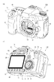
図1(a)、(b)に本発明の電子機器、撮像制御装置、撮像装置の一例としてのデジタルカメラの外観図を示す。図1(a)はデジタルカメラ100の前面斜視図であり、図1(b)はデジタルカメラ100の背面斜視図である。図1において、表示部28は画像や各種情報を表示する、カメラ背面に設けられた表示部である。ファインダー外表示部43は、カメラ上面に設けられた表示部であり、シャッター速度や絞りをはじめとするカメラの様々な設定値が表示される。シャッターボタン61は撮影指示を行うための操作部である。モード切替スイッチ60は各種モードを切り替えるための操作部である。端子カバー40は外部機器との接続ケーブルとデジタルカメラ100とを接続する接続ケーブル等のコネクタ(不図示)を保護するカバーである。
FIGS. 1A and 1B show external views of an electronic apparatus, an imaging control apparatus, and a digital camera as an example of the imaging apparatus according to the present invention. 1A is a front perspective view of the
メイン電子ダイヤル71は操作部70(図2)に含まれる回転操作部材であり、このメイン電子ダイヤル71を回すことで、シャッター速度や絞りなどの設定値の変更等が行える。電源スイッチ72はデジタルカメラ100の電源のON及びOFFを切り替える操作部材である。サブ電子ダイヤル73は操作部70に含まれる回転操作部材であり、選択枠の移動や画像送りなどを行える。十字キー74は操作部70に含まれ、上、下、左、右部分をそれぞれ押し込み可能なキー(4方向キー)である。十字キー74の押した部分に応じた操作が可能である。なお、十字キー74の代わりに、あるいは十字キーに加えて、ポインティングスティックを設けてもよい。SETボタン75は操作部70に含まれ、押しボタンであり、主に選択項目の決定などに用いられる。
The main
LVボタン76は操作部70に含まれ、静止画撮影モードにおいてライブビュー(以下、LV)のONとOFFを切り替えるボタンである。また、LVボタン76は、動画撮影モードにおいては、動画撮影(記録)の開始、停止の指示に用いられる。拡大ボタン77は操作部70に含まれ、撮影モードのライブビュー表示において拡大モードのON、OFF,及び拡大モード中の拡大率の変更を行うための操作ボタンである。また、拡大ボタン77は、再生モードにおいては再生画像を拡大し、拡大率を増加させるための拡大ボタンとして機能する。縮小ボタン78は操作部70に含まれ、拡大された再生画像の拡大率を低減させ、表示された画像を縮小させるためのボタンである。再生ボタン79は操作部70に含まれ、撮影モードと再生モードとを切り替える操作ボタンである。撮影モード中に再生ボタン79を押下することで再生モードに移行し、記録媒体200に記録された画像のうち最新の画像を表示部28に表示させることができる。
The
クイックリターンミラー12は、システム制御部50(図2)から指示されて、不図示のアクチュエータによりアップダウンされる。通信端子10はデジタルカメラ100がレンズ側(着脱可能)と通信を行う為の通信端子である。接眼ファインダー16はフォーカシングスクリーン13(図2)を観察することで、レンズユニット150(図2)を通して得た被写体の光学像の焦点や構図の確認を行うための覗き込み型のファインダー(以下、ファインダー16)である。蓋202は記録媒体200(図2)を格納するためのスロットの蓋である。グリップ部90は、ユーザーがデジタルカメラ100を構えた際に右手で握りやすい形状とした保持部である。
The
Qボタン81は操作部70に含まれる操作ボタンであり、後述するカスタマイズ機能におけるユーザー操作を受け付ける。ゴミ箱ボタン82は操作部70に含まれる操作ボタンであり、画像ファイルの消去や、カスタマイズ可能な設定画面におけるオブジェクトの消去をユーザーが指示するのに用いられる。INFOボタン83は操作部70に含まれる操作ボタンであり、表示部28に表示する画面を切り替えるのに用いられる。MENUボタン84は、表示部28の表示をメニュー画面に遷移させるための操作ボタンである。マルチファンクションボタン85には、デジタルカメラ100の動作状態に応じて様々な機能が割り当てられる。
図2は、本実施形態によるデジタルカメラ100の構成例を示すブロック図である。図2において、レンズユニット150は、交換可能な撮影レンズを搭載するレンズユニットである。レンズ103は通常、複数枚のレンズから構成されるが、ここでは簡略して一枚のレンズのみで示している。通信端子6はレンズユニット150がデジタルカメラ100側と通信を行う為の通信端子であり、通信端子10はデジタルカメラ100がレンズユニット150側と通信を行う為の通信端子である。レンズユニット150は、この通信端子6,10を介してシステム制御部50と通信し、内部のレンズシステム制御回路4によって絞り駆動回路2を介して絞り1の制御を行い、AF駆動回路3を介して、レンズ103の位置を変位させることで焦点を合わせる。
FIG. 2 is a block diagram showing a configuration example of the
AEセンサー17は、レンズユニット150を通した被写体の輝度を測光する。焦点検出部11は、システム制御部50にデフォーカス量情報を出力する。システム制御部50はデフォーカス量情報に基づいてレンズユニット150を制御し、位相差AFを行う。12はクイックリターンミラー(以下、ミラー12)であり、露光、ライブビュー撮影、動画撮影の際にシステム制御部50から指示されて、不図示のアクチュエータによりアップダウンされる。ミラー12は、レンズ103から入射した光束をファインダー16側と撮像部22側とに切替えるためのミラーである。ミラー12は通常時はファインダー16へと光束を導くよう反射させるように配されているが、撮影が行われる場合やライブビュー表示の場合には、撮像部22へと光束を導くように上方に跳ね上がり光束中から待避する(ミラーアップ)。またミラー12はその中央部が光の一部を透過できるようにハーフミラーとなっており、光束の一部を、焦点検出を行うための焦点検出部11に入射するように透過させる。
The
撮影者は、ペンタプリズム14とファインダー16を介して、フォーカシングスクリーン13を観察することで、レンズユニット150を通して得た被写体の光学像の焦点や構図の確認が可能となる。シャッター101は、システム制御部50の制御で撮像部22の露光時間を自由に制御できるフォーカルプレーンシャッターである。撮像部22は光学像を電気信号に変換するCCDやCMOS素子等で構成される撮像素子である。A/D変換器23は、アナログ信号をデジタル信号に変換する。A/D変換器23は、撮像部22から出力されるアナログ信号をデジタル信号に変換するために用いられる。
By observing the focusing
画像処理部24は、A/D変換器23からのデータ、又は、メモリ制御部15からのデータに対し所定の画素補間、縮小といったリサイズ処理や色変換処理を行う。また、画像処理部24では、撮像した画像データを用いて所定の演算処理が行われ、得られた演算結果に基づいてシステム制御部50が露光制御、測距制御を行う。これにより、TTL(スルー・ザ・レンズ)方式のAF(オートフォーカス)処理、AE(自動露出)処理、EF(フラッシュプリ発光)処理が行われる。画像処理部24では更に、撮像した画像データを用いて所定の演算処理を行い、得られた演算結果に基づいてTTL方式のAWB(オートホワイトバランス)処理も行っている。
The
A/D変換器23からの出力データは、画像処理部24及びメモリ制御部15を介して、或いは、メモリ制御部15を介してメモリ32に直接書き込まれる。メモリ32は、撮像部22によって得られA/D変換器23によりデジタルデータに変換された画像データや、表示部28に表示するための画像データを格納する。メモリ32は、所定枚数の静止画像や所定時間の動画像および音声を格納するのに十分な記憶容量を備えている。また、メモリ32は画像表示用のメモリ(ビデオメモリ)を兼ねている。D/A変換器19は、メモリ32に格納されている画像表示用のデータをアナログ信号に変換して表示部28に供給する。こうして、メモリ32に書き込まれた表示用の画像データはD/A変換器19を介して表示部28により表示される。
Output data from the A /
表示部28は、LCD等の表示器上に、D/A変換器19からのアナログ信号に応じた表示を行う。A/D変換器23によって一度A/D変換されメモリ32に蓄積されたデジタル信号をD/A変換器19においてアナログ変換し、表示部28に逐次転送して表示することで、電子ビューファインダとして機能し、スルー画像表示(ライブビュー表示)を行える。
The
ファインダー内液晶表示部41には、ファインダー内表示部駆動回路42を介して、現在オートフォーカスが行われている測距点(フォーカス調整位置)を示す枠(AF枠)や、カメラの設定状態を表すオブジェクトなどが表示される。ファインダー外表示部43には、ファインダー外表示部駆動回路44を介して、シャッター速度や絞りをはじめとするカメラの様々な設定値が表示される。
In the in-finder liquid crystal display unit 41, a frame (AF frame) indicating a distance measuring point (focus adjustment position) where autofocusing is currently performed via the in-finder display
不揮発性メモリ56は、電気的に消去・記録可能なメモリであり、例えばEEPROM等が用いられる。不揮発性メモリ56には、システム制御部50の動作用の定数、プログラム等が記憶される。ここでいう、プログラムとは、本実施形態にて後述する各種フローチャートを実行するためのプログラムのことである。 The non-volatile memory 56 is an electrically erasable / recordable memory, and for example, an EEPROM or the like is used. In the non-volatile memory 56, constants, programs and the like for operation of the system control unit 50 are stored. The program referred to here is a program for executing various flowcharts to be described later in the present embodiment.
システム制御部50は、デジタルカメラ100全体を制御する。前述した不揮発性メモリ56に記録されたプログラムを実行することで、後述する本実施形態の各処理を実現する。52はシステムメモリであり、RAMが用いられる。システムメモリ52には、システム制御部50の動作用の定数、変数、不揮発性メモリ56から読み出したプログラム等を展開する。また、システム制御部50はメモリ32、D/A変換器19、表示部28等を制御することにより表示制御も行う。システムタイマー53は各種制御に用いる時間や、内蔵された時計の時間を計測する計時部である。
The system control unit 50 controls the entire
モード切替スイッチ60、第1シャッタースイッチ62、第2シャッタースイッチ64、操作部70はシステム制御部50に各種の動作指示を入力するための操作手段である。モード切替スイッチ60は、システム制御部50の動作モードを静止画記録モード、動画撮影モード、再生モード等のいずれかに切り替える。静止画記録モードに含まれるモードとして、オート撮影モード、オートシーン判別モード、マニュアルモード、絞り優先モード(Avモード)、シャッター速度優先モード(Tvモード)がある。また、撮影シーン別の撮影設定となる各種シーンモード、プログラムAEモード、カスタムモード等がある。モード切替スイッチ60で、メニューボタンに含まれるこれらのモードのいずれかに直接切り替えられる。あるいは、モード切替スイッチ60でメニューボタンに一旦切り換えた後に、メニューボタンに含まれるこれらのモードのいずれかに、他の操作部材を用いて切り替えるようにしてもよい。同様に、動画撮影モードにも複数のモードが含まれていてもよい。
The
第1シャッタースイッチ62は、デジタルカメラ100に設けられたシャッターボタン61の操作途中、いわゆる半押し(撮影準備指示)でONとなり第1シャッタースイッチ信号SW1を発生する。第1シャッタースイッチ信号SW1により、AF(オートフォーカス)処理、AE(自動露出)処理、AWB(オートホワイトバランス)処理、EF(フラッシュプリ発光)処理等の動作を開始する。第2シャッタースイッチ64は、シャッターボタン61の操作完了、いわゆる全押し(撮影指示)でONとなり、第2シャッタースイッチ信号SW2を発生する。システム制御部50は、第2シャッタースイッチ信号SW2により、撮像部22からの信号読み出しから記録媒体200に画像データを書き込むまでの一連の撮影処理の動作を開始する。
During the operation of the
操作部70の各操作部材は、表示部28に表示される種々の機能オブジェクトを選択操作することなどにより、場面ごとに適宜機能が割り当てられ、各種機能ボタンとして作用する。機能ボタンとしては、例えば終了ボタン、戻るボタン、画像送りボタン、ジャンプボタン、絞込みボタン、属性変更ボタン等がある。例えば、メニューボタンが押されると各種の設定可能なメニュー画面が表示部28に表示される。利用者は、表示部28に表示されたメニュー画面と、上下左右の4方向ボタン(十字キー74)やSETボタン75とを用いて直感的に各種設定を行うことができる。
Each operation member of the
操作部70は、ユーザーからの操作を受け付ける入力部としての各種操作部材である。操作部70には、少なくとも、シャッターボタン61、メイン電子ダイヤル71、電源スイッチ72、サブ電子ダイヤル73、十字キー74、SETボタン75が含まれる。また、LVボタン76、拡大ボタン77、縮小ボタン78、再生ボタン79、Qボタン81、ゴミ箱ボタン82、INFOボタン83、MENUボタン84、マルチファンクションボタン85、が含まれる。
The
電源制御部80は、電池検出回路、DC−DCコンバータ、通電するブロックを切り替えるスイッチ回路等により構成され、電池の装着の有無、電池の種類、電池残量の検出を行う。また、電源制御部80は、その検出結果及びシステム制御部50の指示に基づいてDC−DCコンバータを制御し、必要な電圧を必要な期間、記録媒体200を含む各部へ供給する。
The power supply control unit 80 includes a battery detection circuit, a DC-DC converter, a switch circuit for switching a block to be energized, and the like, and detects the presence or absence of a battery, the type of battery, and the battery remaining amount. Further, the power control unit 80 controls the DC-DC converter based on the detection result and an instruction of the system control unit 50, and supplies necessary voltages to the respective units including the
電源部30は、アルカリ電池やリチウム電池等の一次電池やNiCd電池やNiMH電池、Li電池等の二次電池、ACアダプター等からなる。記録媒体I/F18は、メモリカードやハードディスク等の記録媒体200とのインターフェースである。記録媒体200は、撮影された画像を記録するためのメモリカード等の記録媒体であり、半導体メモリや磁気ディスク等から構成される。
The
通信部54は、無線または有線ケーブルによって接続し、映像信号や音声信号の送受信を行う。通信部54は無線LAN(Local Area Network)やインターネットとも接続可能である。通信部54は撮像部22で撮像した画像(スルー画像を含む)や、記録媒体200に記録された画像を送信可能であり、また、外部機器から画像データやその他の各種情報を受信することができる。
The
姿勢検知部55は重力方向に対するデジタルカメラ100の姿勢を検知する。姿勢検知部55で検知された姿勢に基づいて、撮像部22で撮影された画像が、デジタルカメラ100を横に構えて撮影された画像であるか、縦に構えて撮影された画像なのかを判別可能である。システム制御部50は、姿勢検知部55で検知された姿勢に応じた向き情報を撮像部22で撮像された画像の画像ファイルに付加したり、画像を回転して記録したりすることが可能である。姿勢検知部55としては、加速度センサーやジャイロセンサーなどを用いることができる。
The
次に、以上のような構成を備えた本実施形態のデジタルカメラ100における撮影時の各種設定等を行うための撮影設定画面(以下、設定画面)をカスタマイズするカスタマイズ設定機能およびその操作方法について説明する。また、そのようなカスタマイズ設定機能を用いてカスタマイズされた設定画面を用いて各種設定値の変更を行う際の制御および操作について説明する。
Next, a customization setting function for customizing a shooting setting screen (hereinafter referred to as a setting screen) for performing various settings at the time of shooting in the
カスタマイズ設定機能は、シャッタースピード、露出補正、ホワイトバランス等の、撮影時におけるパラメータの設定や、センサークリーニングなどの所定の機能の実行を指示するための複数の設定項目を一覧表示する設定画面をカスタマイズする機能である。設定画面には、図3により後述するようにそれぞれの設定項目に対応する複数のオブジェクトが表示される。ユーザーは設定画面に表示されたオブジェクトをみることでデジタルカメラ100の設定状態を把握できるとともに、設定画面で選択したオブジェクトに対応する設定項目の設定値を変更することが可能である。したがって、ユーザーは、設定画面により迅速な設定が行える。カスタマイズ設定機能において、ユーザーは、設定画面にオブジェクトとして表示させる設定項目の選択、オブジェクトの表示サイズの選択、オブジェクトの画面上への配置位置の選択をすることが可能である。なお、以降に説明する各フローチャートの処理はシステム制御部50が不揮発性メモリ56に格納されたプログラム、あるいはシステムメモリ52に展開されたプログラムを実行することにより実現される。
The customization setting function customizes the setting screen that displays a list of multiple setting items for instructing settings of parameters at the time of shooting such as shutter speed, exposure correction, white balance, etc., and sensor cleaning etc. Function. On the setting screen, a plurality of objects corresponding to the respective setting items are displayed as described later with reference to FIG. The user can grasp the setting state of the
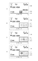
図3(a)〜(c)は、本実施形態のカスタマイズ設定機能によりユーザーによるカスタマイズが可能な設定画面300の一例を示す図である。設定画面300は、後述するINFOボタン83の操作による画面の切り替えにより、表示部28に表示される画面の一つである。図3(a)に示される設定画面300では、F値、シャッタースピード、ISO値、露出補正値などの設定項目のオブジェクトが表示されており、各オブジェクトには、対応する設定項目の現在の設定状態が示されている。たとえば、オブジェクト301aはシャッタースピードの設定であり、シャッタースピードが1/8000秒に設定されていることを示している。各オブジェクトは、後述する配置枠を単位とした大きさ(配置枠の整数倍の大きさ)を有し、配置枠にしたがって配置されている。また、設定画面のオブジェクトのレイアウトはカスタマイズ機能により編集可能である。
FIGS. 3A to 3C are diagrams showing an example of a
図3(b)は、設定画面300を用いたユーザーによる設定操作の一例として、ISO感度を設定する際の操作状態を示している。Qボタン81の押下によりユーザーによる移動操作が可能なカーソル311が表示される。ユーザーは、カーソル311をISO感度の設定項目に対応するオブジェクト301bの位置に移動させることで、メイン電子ダイヤル71やサブ電子ダイヤル73を用いてISO感度の設定値を変更することが可能になる。なお、このときガイダンスエリア302には、カーソル311により現在選択されているオブジェクトに対応する設定項目(この例ではISO感度)を示す表示がなされる。また、カーソル311は、ユーザー操作に応じてオブジェクトの存在する位置を移動し、カーソル311の枠の大きさはオブジェクトの大きさに応じて変化する。このような設定操作の詳細については後述する。また、図3(c)は、図3(a)の状態から、カスタマイズ設定機能による設定画面300のレイアウト編集(詳細は後述)により、ホワイトバランスを設定するためのオブジェクト301cが設定画面300に追加された様子を示している。
FIG. 3B shows an operation state when setting the ISO sensitivity as an example of the setting operation by the user using the
図4(a)は、上述のようなカスタマイズ設定機能による、設定画面の編集を行うレイアウト編集処理において表示される編集画面400の一例を示す図である。後述の手順によりカスタマイズ設定機能を起動することにより、編集画面400が表示部28に表示される。図4(a)に示した編集画面400は、図3(a)に示した設定画面300に対応している。ユーザーは、デジタルカメラ100におけるカスタマイズ設定機能を用いて、追加させたい設定項目を選択し、選択した設定項目について設定画面に表示させるオブジェクトの大きさや表示のさせ方を設定し、配置位置を決定することができる。これにより、ユーザーは、設定画面に所望の設定項目のオブジェクトを表示させることができる。
FIG. 4A is a view showing an example of the
配置枠401は、所定サイズを有し、設定項目に対応したオブジェクトを配置する単位(単位領域)である。配置枠401は、カスタマイズ設定機能による編集画面400の、オブジェクトが配置されていない部分に表示される。配置枠401は画面上に複数並べられており、図4(a)の例では縦4枠横6枠で並んでいる。図4(a)の例では、たとえばシャッタースピードの設定項目としてのオブジェクト301aが、配置枠横2枠×縦1枠分の大きさ(以下、2×1のように記載することもある)で、画面上の複数配置枠のうち1段目中の左から3枠目に配置されている。なお、図3(a)〜(c)に示される設定画面300では、配置枠401は表示されない。また、配置枠の並び方、配置枠の数は上述した構成に限られるものではなく、配置枠の大きさを小さくすればするほど、オブジェクトの配置位置や大きさの自由度が増す。配置枠を1画素のサイズとすることも可能である。
The
カーソル411は、オブジェクトまたは配置枠401を囲む枠表示であり、現在のカーソル位置を示す。カーソル411の大きさは、オブジェクトが配置されていない配置枠401にある場合は配置枠401の一つ分の大きさとなり、オブジェクトが配置されている配置枠401にある場合にはそのオブジェクトの表示サイズに応じて変化する。たとえば、図4(a)ではカーソル位置が1×1の大きさのオブジェクト301dにあり、カーソル411の大きさは配置枠401の一つ分の大きさである。他方、図4(b)では、カーソル位置が2×1の大きさのオブジェクト301bにあり、カーソル411の大きさも2×1(配置枠401の二つ分の大きさ)となっている。また、図4(c)では、カーソル411がオブジェクトの配置されていない配置枠にある様子が示されている。
A
ガイダンスエリア402には、編集画面400における操作ガイドが表示される。操作ガイドは、状態によって操作可能となる操作内容とその操作が割り当てられる操作部材を示すアイコンを1組にした表示を行う。図示の例では、Qボタン81のアイコンとその操作内容(オブジェクトの新規追加)、ゴミ箱ボタン82のアイコンとその操作内容(オブジェクトの削除)が表示されている。
In the
次に、本実施形態のカスタマイズ設定機能の動作について説明する。なお、カスタマイズ設定機能はたとえば以下のような操作により起動される。まず、MENUボタン84の押下に応じて、システム制御部50は、図5(a)に示すようなメニュー画面500を表示部28に表示する。ユーザーが、十字キー74を操作して「クイック設定カスタマイズ」のメニュー項目にカーソル511を合わせてSETボタン75を押下すると、システム制御部50は、カスタマイズ設定機能を起動する。システム制御部50は、カスタマイズ設定機能を起動すると、まず、図5(b)のようなクイック設定カスタマイズのメニュー画面520を表示する。このメニュー画面520において「レイアウト編集開始」のメニュー項目にカーソル511を合わせてSETボタン75が押下されると、カスタマイズ設定機能は、図5(c)のようなガイド画面540の表示を行う。そして、SETボタン75の押下に応じて、図4(a)に示されるような編集画面400を表示し、ユーザーによる設定項目の変更が可能なレイアウト編集処理を開始する。なお、図5(c)に示すガイド画面540の表示は省略してもよい。
Next, the operation of the customization setting function of this embodiment will be described. The customization setting function is activated, for example, by the following operation. First, in response to the depression of the
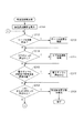
図6は、上述した操作(メニュー画面500における「レイアウト編集開始」の選択)により起動される、カスタマイズ設定機能によるレイアウト編集処理を説明するフローチャートである。レイアウト編集処理を開始すると、システム制御部50は設定画面に表示させるオブジェクトを変更するための編集画面400を表示する(S601)。システム制御部50は、編集画面400の表示を開始するときに既に配置されたオブジェクトが存在していれば、それらを不揮発性メモリ56から読み出して編集画面400を構成する。たとえば、システム制御部50は、図3(a)に示されるような設定画面300が既に構成されていれば、設定画面300を構成するオブジェクトを読み出して編集画面を構成する。この結果、図4(a)に示す編集画面400が表示される。
FIG. 6 is a flowchart illustrating layout editing processing by the customization setting function, which is activated by the above-described operation (selection of “layout editing start” on the menu screen 500). When the layout editing process is started, the system control unit 50 displays an
次に、システム制御部50は、操作部70からカーソル移動指示(たとえば、十字キー74による指示)が発生したか否かを判定する(S602)。カーソル移動指示が発生していた場合、システム制御部50は、カーソルの移動指示により指示された方向にカーソル411を移動する(S603)。上述したように、カーソル411は、オブジェクトが配置されていなければ配置枠401を単位として、オブジェクトが配置されていればそのオブジェクトの大きさを単位として移動し、そのサイズは配置枠の大きさまたはオブジェクトの大きさに従う。
Next, the system control unit 50 determines whether or not a cursor movement instruction (for example, an instruction by the cross key 74) has been generated from the operation unit 70 (S602). If a cursor movement instruction has been issued, the system control unit 50 moves the
また、システム制御部50は、操作部70のゴミ箱ボタン82が押下されたと判断すると(S604)、カーソル411の位置(カーソル位置)にオブジェクトが存在するか否かを判断する(S605)。カーソル位置にオブジェクトが存在していれば、そのオブジェクトの表示を消去する(S606)。たとえば、図4(b)に示されるように、ISOの設定項目であるオブジェクト301bへカーソル411を移動してゴミ箱ボタン82が押下されると、カーソル位置にあるオブジェクト301bが削除され、図4(c)の状態となる。オブジェクトの消去を行った場合は、システム制御部50は、撮影時の設定項目のカスタマイズ設定の画面の項目の更新を不揮発性メモリ56へ記憶する(S606)。
When the system control unit 50 determines that the
また、システム制御部50は、Qボタン81が押下されたと判断すると(S607)、オブジェクトとして追加表示する設定項目を選択するための設定項目選択処理を開始する(S608)。S608における設定項目選択処理については、図7のフローチャートの参照により後述する。
If the system control unit 50 determines that the
また、システム制御部50は、SETボタン75が押下されたと判断すると(S609)、カーソル411の位置にオブジェクトが存在するかどうかを判定する(S610)。カーソル411の位置にオブジェクトが存在しないと判定された場合は(すなわち、カーソル411の位置が空きの配置枠である場合)、設定画面へのオブジェクトの追加を行うための設定項目選択処理(図7)を開始する(S611)。他方、カーソル411の下にオブジェクトが存在する場合、システム制御部50は、オブジェクト配置処理を開始する(S612)。オブジェクト配置処理では、ユーザーは、カーソル411の下にあるオブジェクトを任意の位置に移動し、配置することができる。オブジェクト配置処理については図11のフローチャートにより後述する。
When the system control unit 50 determines that the
例えば、図4(c)に示されるように、オブジェクトの存在しない配置枠にカーソル411が存在した状態でSETボタン75が押下されると、設定項目選択処理が開始される(S609、S610、S611)。また、図4(b)のようにカーソル位置にオブジェクト(この例ではISO感度設定を示すオブジェクト301b)が存在する状態でSETボタン75が押下されると、システム制御部50は、オブジェクト配置処理を開始する(S609、S610、S612)。オブジェクト配置処理の実行により、ユーザーはオブジェクト301bの位置を変更することが可能になる。
For example, as shown in FIG. 4C, when the
また、システム制御部50は、MENUボタン84が押下されたと判定すると(S613)、レイアウト編集処理を終了して図5(b)に示される、レイアウト編集処理に移行するためのメニュー画面511を表示する(S614)。また、レイアウト編集処理の終了操作を検出すると、レイアウト編集処理が終了する(S615)。たとえばシャッターボタン61における第1シャッタースイッチ62がONしたことが検出されると、システム制御部50はレイアウト編集処理を終了し、デジタルカメラ100を撮影動作へ遷移させる。これによって撮影待機状態に移行する。この際、レイアウト編集処理を始める前の撮影待機状態で、後述する撮影機能設定画面(カスタム)を表示していた場合は、再び撮影機能設定画面(カスタム)を表示する(例えば図3(a)の表示)。なお、レイアウト編集処理を終了して撮影待機状態に移行した場合には、レイアウト編集処理を始める前の撮影待機状態でどの画面を表示していたかに関わらず、撮影機能設定画面(カスタム)を表示してもよい。すなわち、後述する図19で説明するINFOボタン83の押下毎に切替表示できる画面のうちどの画面を表示していたかに関わらず、撮影機能設定画面(カスタム)を表示してもよい。このようにすることで、ユーザーはレイアウト編集処理の結果が撮影機能設定画面(カスタム)にどのように反映されたかを確認することができる。
If the system control unit 50 determines that the
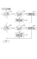
次に、前述のS608、S611において開始する設定項目選択処理について図7のフローチャートを用いて説明する。設定項目選択処理では、設定画面にオブジェクトとして表示させる設定項目の選択、および、その選択された設定項目に対応するオブジェクトの表示スタイルの選択を行うことができる。 Next, the setting item selection process started in the above-described S608 and S611 will be described using the flowchart of FIG. In the setting item selection process, it is possible to select a setting item to be displayed as an object on the setting screen and to select a display style of an object corresponding to the selected setting item.
まず、システム制御部50は、オブジェクトとして表示させる設定項目を選択するための設定項目選択画面を表示部28に表示する(S701)。この画面では、カスタマイズ可能な設定画面にオブジェクトとして新規配置する設定項目をユーザーに選択させることを行う。図9(a)は、本実施形態による設定項目選択画面900の表示例を示す図である。設定項目選択画面900において、ユーザーは十字キー74の操作によりカーソル901を上下に移動し、所望の設定項目を選択することができる。設定項目902(露出補正/AEB)は、カスタマイズ可能な設定画面に既にオブジェクトとして配置されている項目であるため、グレーアウト表示となっており、この画面では選択できない。ただし、1つの設定画面に同一設定項目の複数のオブジェクトを選択配置可能な場合はグレーアウトせず、設定項目選択画面900より選択可能とする。設定項目903(ホワイトバランス)は、対応するオブジェクトを設定画面に新規に配置することが可能な項目である。なお、設定項目902、903において名称表示により設定項目を明示したが、これに限られるものではなく、たとえば、キャラクタを用いたアイコン表現を用いてもよい。
First, the system control unit 50 displays a setting item selection screen for selecting a setting item to be displayed as an object on the display unit 28 (S701). In this screen, the user is allowed to select a setting item to be newly arranged as an object on the customizable setting screen. FIG. 9A is a view showing a display example of the setting
システム制御部50は、操作部70においてカーソル移動指示(たとえば、十字キー74による上下指示の操作)が発生したと判定すると(S702)、指示された方向へカーソル901を移動する(S703)。なお、この際に、移動先の設定項目がグレーアウト表示されている場合(選択不可となっている場合)は、その項目をスキップして、次の選択が可能な項目に移動するようにしてもよい。たとえば、図9(a)の状態において下方向へのカーソル移動指示が発生すると、カーソル901は露出補正/AEBの設定項目902をスキップして記録画質の設定項目へ移動するようにしてもよい。また、システム制御部50は、MENUボタン84が押下されたと判断すると(S704)、ひとつ前の画面に戻る(S705)。ここでは、設定項目選択画面へ遷移する前の画面、すなわち、編集画面(S601)へ遷移する。
When the system control unit 50 determines that the cursor movement instruction (for example, the operation of the up and down instruction by the cross key 74) is generated in the operation unit 70 (S702), the system control unit 50 moves the
また、システム制御部50は、SETボタン75が押下されたと判断すると(S706)、カーソル901のカーソル位置にある設定項目が複数のスタイルを持つか否かを判断する(S707)。複数のスタイルを持たないと判断された場合、システム制御部50は、画面を編集画面400に戻し、カーソル411の位置に当該設定項目に対応するオブジェクトを配置する(S710)。そして、システム制御部50は、そのオブジェクトを設定画面に配置、確定するためのオブジェクト配置処理を開始する(S711)。オブジェクト配置処理については、図11のフローチャートにより後述する。他方、設定項目が複数のスタイルを持つ場合は、システム制御部50は、スタイル選択処理を開始する(S708)。スタイル選択処理については図8のフローチャートにより後述する。また、システム制御部50は、設定項目選択処理の終了操作を検出すると、本処理を終了する(S709)。たとえばシャッターボタン61における第1シャッタースイッチ62がONしたことにより、システム制御部50は設定項目選択処理を終了する。この処理は、前述のS615でYesとなった場合と同様の処理である。
If the system control unit 50 determines that the
次に、上述のS708で実行されるスタイル選択処理について、図8のフローチャートを参照して説明する。システム制御部50は、スタイル選択処理を開始すると、まず、スタイル選択画面を表示する(S801)。図9(b)、図9(c)は、スタイル選択画面の一例を示しており、ここでは設定項目がホワイトバランスの場合のスタイル選択画面920が例示されている。図9(a)の設定項目選択画面900で、ホワイトバランスの設定項目903にカーソル901を移動した状態でSETボタン75が押下されると、ホワイトバランスに関するスタイル選択画面920が表示される。スタイル選択画面において、ユーザーは、カスタマイズ設定画面に配置するオブジェクトの表示サイズや、オブジェクトにおける情報の表示のさせ方(以降、これらを総称してスタイルという)を選択することができる。
Next, style selection processing executed in the above-described S708 will be described with reference to the flowchart in FIG. When starting the style selection process, the system control unit 50 first displays a style selection screen (S801). FIG. 9B and FIG. 9C show an example of the style selection screen, and here, the
スタイル選択画面920において、設定項目名表示921には、スタイルの選択対象となっている設定項目の名称が表示される。カーソル922は、たとえば十字キー74の上下操作により移動し、ユーザーに表示サイズを選択させる。スタイル表示923には、カーソル922によって現在選択されている表示サイズに応じたオブジェクトが表示される。カーソル922により選択されているスタイル(表示サイズ)が図9(b)に示される「1×1」から図9(c)に示されるように「2×1」に変更されると、スタイル表示923に表示されるオブジェクトもこれに応じて変化する。図9(b)、図9(c)から明らかなように、オブジェクトには、表示サイズの相違に応じて異なる情報量が表現されることになる。たとえば、ホワイトバランスを色温度で設定する場合、1×1の表示サイズのオブジェクトでは色温度の値を表示しようとするとその表示サイズが小さくなってしまうので、温度値の表示は行われない。これに対して、図9(c)のように2×1の表示サイズになると、ホワイトバランスの色温度設定値を同時に表示させることが可能になる。また、後述するが、1×1の表示サイズのオブジェクトではオート、プリセット(晴天、曇天、電球等)、色温度指定等のホワイトバランスの種別を設定できるが、色温度の設定値を変更することはできない。これに対し、2×1の表示サイズでは、色温度指定が選択された場合に色温度の設定を行うことが可能となる。ユーザーは、1つの選択項目に関して、オブジェクトの表示サイズとオブジェクトが扱う情報量のバランスを考慮して所望のオブジェクトを選択することができる。
In the
以上のように、システム制御部50は、スタイル選択処理を開始すると、図9(b)、図9(c)に示すようなスタイル選択画面920を表示し、選択されている設定項目に対応するオブジェクトについて選択可能な表示スタイルを提示する。システム制御部50は、十字キー74の上下操作によるカーソルの移動指示が発生したと判定すると(S802)、移動指示の方向にカーソル922を移動する(S803)。なお、スタイル表示923では、提供される情報量をユーザーが把握できるように、その表示サイズのオブジェクトが表示できるすべての情報を見せるようにする。たとえば、図9(c)に示す色温度のスタイル表示923では、設定可能なケルビン値の最大値を表示することにより表示可能な桁数を提示する。また、たとえば図29(b)の、調光補正値のオブジェクト2931をスタイル表示する場合は、外部ストロボの接続の有無にかかわらずアイテム2933を表示し、調光補正値2934はその最大値とともに、+および−の符号を表示する。
As described above, when the style selection process is started, the system control unit 50 displays a
また、システム制御部50は、SETボタン75が押下されたと判断すると(S804)、画面を図4で説明した編集画面に戻し、カーソル411の位置に選択されたオブジェクトを配置する(S805)。そして、カーソル922が現在選択している表示サイズのオブジェクトを設定画面に配置、確定するためのオブジェクト配置処理を開始する(S806)。オブジェクト配置処理については図11のフローチャートにより後述する。また、システム制御部50は、MENUボタン84の押下を検出すると(S807)、一つ前の画面に戻るための画面遷移を行う(S808)。ここでは、スタイル選択画面920へ遷移する前の画面である、設定項目選択画面900(S701)に戻ることになる。また、システム制御部50は、スタイル選択処理の終了操作が発生したと判定すると(S809)スタイル選択処理を終了する。他方、終了操作が発生していないと判定された場合は、処理はS802に戻る。たとえばシャッターボタン61における第1シャッタースイッチ62がONしたことにより、システム制御部50はスタイル選択処理を終了する。この処理は、前述のS615でYesとなった場合と同様の処理である。
If the system control unit 50 determines that the
スタイル選択についてさらに別の設定項目について説明する。図10は設定項目選択画面900においてAFフレーム(図9では不図示)の設定項目(フォーカス項目)が選択された場合に表示されるスタイル選択画面の例を示す図である。設定項目がAFフレーム(フォーカスフレーム、測距枠、フォーカス調整)の場合、対応するオブジェクト(表示アイテム)の表示スタイル(サイズ・面積)は、「1×1」と「3×2」の二通りである。図10(a)において、スタイル選択画面1000の設定項目名表示1001には、スタイルの選択対象となっている「AFフレーム」が示されている。カーソル1002の移動により、ユーザーはAFフレームの表示スタイルとして「1×1」か「3×2」を選択することができる。また、スタイル表示1003には、カーソル1002で選択している表示サイズに応じたオブジェクトが表示されている。図10(a)では、カーソル1002が表示サイズ「1×1」を選択している状態が示されている。
Another setting item of the style selection will be described. FIG. 10 is a view showing an example of a style selection screen displayed when a setting item (focus item) of an AF frame (not shown in FIG. 9) is selected in the setting
図10(b)に示されるように、カーソル1002を表示サイズ「3×2」に移動させると、表示サイズ「3×2」に応じたオブジェクトの例がスタイル表示1003に表示される。表示サイズの相違に応じて、表現される設定値の情報が異なる。すなわち、表示サイズ「1×1」ではAFフレームの測距エリア選択による設定値を示すオブジェクトが、表示サイズ「3×2」ではAFフレームの測距エリア選択および測距点選択による設定値を示すオブジェクトが表示される。
As shown in FIG. 10B, when the
次に、S612,S710、S805で開始、実行されるオブジェクト配置処理について、図11のフローチャートを用いて説明する。オブジェクト配置処理において、ユーザーは、カーソル411のカーソル位置にあるオブジェクトをカーソル411の移動操作により任意の位置に移動し、SETボタン75の押下によりそのカーソル位置にオブジェクトを配置することができる。上述した設定項目選択処理またはスタイル選択処理からオブジェクト配置処理が起動された場合、設定項目選択画面900で選択した設定項目に対応し、かつ、スタイル選択画面920、1000で選択したスタイルのオブジェクトが編集画面400に配置される。また、後述のように、そのオブジェクトはユーザー操作により任意の位置に配置される。
Next, object placement processing started and executed in S612, S710, and S805 will be described using the flowchart of FIG. In the object placement processing, the user can move the object located at the cursor position of the
オブジェクト配置処理が開始すると、システム制御部50は、編集画面400においてカーソル411の位置にあるオブジェクトを保持状態とし(S1101)、保持状態となったオブジェクトの点滅表示を開始する(S1102)。たとえば、図12(a)に示される状態の編集画面400においてSETボタン75が押下されると(S609、S610)、編集画面400においてカーソル位置にあるオブジェクト1201が保持状態となる。本実施形態では、保持状態であることを示すために、図12(b)に示すように、移動可能な方向の表示を有するカーソル1211を表示する。保持されたオブジェクトはオブジェクト配置処理による操作対象のオブジェクトとなる。
When the object arrangement processing starts, the system control unit 50 holds the object at the position of the
また、図4(a)に示される編集画面400においてカーソル411を左下角の配置枠に移動した後、設定項目選択処理によりホワイトバランスに対応する1×1の表示サイズのオブジェクトが選択された場合も、図12(b)に示すような表示となる。すなわち、図9(a)の設定項目選択画面900で「ホワイトバランス」が選択され、図9(b)のスタイル選択画面920で「1×1」のスタイルが選択され、SETボタン75が押下されると、図12(b)に示されるような表示となる。この新たなオブジェクトの表示位置は、設定項目選択処理を開始する直前のカーソル411の位置である。すなわち、設定項目選択画面900で選択された設定項目のオブジェクトは、オブジェクト配置処理の起動時に自動的に操作対象のオブジェクトとなる。
Further, after moving the
また、システム制御部50は、保持状態を示すカーソル1211でオブジェクトを保持している間、保持されているオブジェクトを点滅表示させるとともにガイダンスエリア402の表示内容を、図12(b)に示すように変更する。ガイダンスエリア402には、SETボタン75で配置確定すること(S1112、S1113)、INFOボタン83でスタイル選択処理が開始されオブジェクトのサイズ変更ができること(S1110、S1111)が示されている。なお、カーソル1211はオブジェクトを保持した状態のカーソル枠であり、カーソルがオブジェクトを保持している状態あることを明示するために、移動可能方向への方向指示表示を伴っている。また、オブジェクトの点滅とともにカーソル1211を点滅させてもよい。
In addition, while the system control unit 50 holds the object with the
また、本実施形態では、オブジェクトの表示範囲と少なくとも一部が重なる既存のオブジェクトがあればその表示形態を変更する(S1103)。本実施形態では、オブジェクトをグレースケールで表示するグレー表示に変更する。以上のように保持状態のオブジェクトを点滅表示、重複する既存のオブジェクトをグレー表示することで、カーソル位置に既に配置されているオブジェクトやその設定項目、保持状態のオブジェクトの配置により削除されるオブジェクトをユーザーに明示できる。すなわち、新たに配置されるオブジェクトが点滅表示されるため、消去対象となるオブジェクトは、新たに配置されるオブジェクトが非表示となっている期間にその全体が現われることになる。このような表示によりユーザーは新たに配置されるオブジェクトとそれにより消去されるオブジェクトを直ちに把握することができる。なお、保持状態のオブジェクトと既存のオブジェクトの両方を視認可能にする表示形態は、上述した点滅表示に限られるものではなく、たとえば保持されているオブジェクトを半透明にして表示したり、警告文を表示したりするようにしてもよい。また、削除対象となるオブジェクトを明示する表示形態としてオブジェクトをグレー表示する例を示したが、これに限られるものではなく、たとえば表示輝度を下げるなど、通常の表示状態と区別できるようにすればよい。 In the present embodiment, if there is an existing object at least a part of which overlaps with the display range of the object, the display mode is changed (S1103). In the present embodiment, the object is changed to gray display in gray scale. As described above, by blinking the objects in the holding state and displaying the overlapping existing objects in gray, the objects already arranged at the cursor position, the setting items thereof, and the objects to be deleted by the arrangement of the objects in the holding state are displayed. Explicit to the user. That is, since the newly arranged object is displayed in a blinking manner, the entire object to be deleted appears during a period in which the newly arranged object is not displayed. Such a display allows the user to immediately grasp the newly placed object and the object to be erased thereby. Note that the display form that allows both the holding state object and the existing object to be visible is not limited to the above-described blinking display, and for example, the held object may be displayed semitransparently or a warning statement may be displayed. It may be displayed. In addition, although an example in which an object is displayed in gray as a display form for clearly indicating an object to be deleted is shown, the present invention is not limited thereto. For example, if it is distinguishable from a normal display state Good.
システム制御部50は、十字キー74による上下左右方向への指示を検出すると(S1104)、移動指示の方向へカーソル1211とそれに保持されているオブジェクトを移動する(S1105)。すなわちカーソルへの移動指示は操作対象のオブジェクトの移動指示でもある。オブジェクト配置処理では、カーソルの移動指示に応じて、カーソル1211およびオブジェクトを、既存のオブジェクトの存否にかかわらず配置枠を単位として移動する。たとえば、図12(b)の表示状態において右方向へ移動する指示が検出されると、図13(a)に示すように、一つの配置枠の分だけ右へカーソル1211と保持されているオブジェクト1201が移動する。なお、編集画面におけるカーソルの移動は配置枠を単位とするが、設定画面(例えば、図3の設定画面300)においては、カーソルは画面に配置されているオブジェクトの間を移動する。
When the system control unit 50 detects an instruction in the up, down, left, and right directions with the cross key 74 (S1104), the system control unit 50 moves the
次に、システム制御部50は、移動したカーソル1211のカーソル位置に既に別のオブジェクトが配置されている場合、オブジェクトの表示範囲と少なくとも一部が重なる既存のオブジェクトがあればその表示形態を変更する(S1106)。この処理は、S1103の処理と同様である。上述のように、本実施形態では、システム制御部50は、そのような既存のオブジェクトをグレー表示に変更し、ガイダンスエリア402にその旨を示す警告文を表示する。また、保持状態のオブジェクトの移動により、その全体が保持状態のオブジェクトの表示範囲外に出たオブジェクトについては、その表示形態を、変更された状態(グレー表示)から元の状態に戻す(S1107)。以上のようにカーソル1211とそれに保持されているオブジェクトは点滅表示しており、既に割り当てられていたオブジェクトの表示形態が変更される。そして、保持されているオブジェクトの非表示時には、その下に存在するオブジェクトが見えるようになる。そのため、ユーザーは、移動先において重なったオブジェクトが存在するか否か、存在するのであればその設定項目の内容、新たなオブジェクトの配置により消去されるオブジェクト(設定項目)を直ちに認識することができる。
Next, when another object is already arranged at the cursor position of the moved
たとえば、図13(a)の例では、カーソル1211の移動により、オブジェクト1201の表示範囲に別の設定項目である「ONE SHOT」に対応したオブジェクト1311が配置されている。したがって、既存のオブジェクト1311はグレー表示され、ガイダンスエリア402には、警告文として「下にある項目は削除されます」が表示される。また、保持されているオブジェクト1201は点滅表示しているため、オブジェクト1201が非表示となる期間は、ユーザーは既存のオブジェクト1311の全体を観察することができる。なお、図13(a)の状態からカーソル1211が左に移動すれば、図12(b)のようになり、システム制御部50は、その全体がオブジェクト1201の表示範囲外となったオブジェクト1311の表示をグレー表示から通常の表示に戻す。
For example, in the example of FIG. 13A, an
システム制御部50は、MENUボタン84の押下を検出すると(S1108)、一つ前の画面に戻るための画面遷移を行う(S1109)。たとえば、オブジェクト配置処理が編集画面400から開始されたのであれば(図6のS612)、MENUボタン84の押下に応じて編集画面400の表示に戻る。あるいは、オブジェクト配置画面が設定項目選択画面またはスタイル選択画面(図7のS710、図8のS805)から遷移してきたのであれば、設定項目選択画面900またはスタイル選択画面920,1000に戻ることになる。
When the system control unit 50 detects that the
システム制御部50は、INFOボタン83の押下を検出すると(S1110)、スタイル選択画面920,1000へ画面を遷移し、図8のスタイル選択処理を再開する(S1111)。この場合、スタイル選択処理の対象となる設定項目は、カーソルによって現在保持されているオブジェクトに対応する設定項目である。たとえば、図12(b)の状態でINFOボタン83が押下されると、ホワイトバランスのスタイル選択画面920(図9(b))が表示される。また、システム制御部50は、SETボタン75が押下されたことを検出すると(S1112)、現在のカーソル位置に選択設定項目を配置確定する処理(配置確定処理)を開始する(S1113)。すなわち、SETボタン75の押下は、保持しているオブジェクトの配置を確定するための確定指示である。配置確定処理については、図14を参照して後述する。たとえば、図13(a)の状態でSETボタン75が押下され、配置確定処理が実行されたとする。この場合、システム制御部50は、カーソル1211が保持しているオブジェクト1201の配置を現在のカーソル位置に確定し、カーソルを図13(b)のように方向表示がないカーソル411に戻す。また、新たに配置されたオブジェクト1201と少なくともその一部が重なって配置されていた既存のオブジェクト1311は、画面から削除される。
When the system control unit 50 detects that the
システム制御部50は、オブジェクト配置処理の終了操作を検出すると本処理を終了し(S1114)、終了操作を検出していない場合は、処理はS1104に戻る。たとえばシャッターボタン61における第1シャッタースイッチ62がONしたことにより、システム制御部50はオブジェクト配置処理を終了する。
When the system control unit 50 detects an end operation of the object placement process, the system control unit 50 ends the process (S1114). When the end operation is not detected, the process returns to S1104. For example, when the
次に、図14のフローチャートを参照して、本実施形態による配置確定処理を説明する。配置確定処理では、カーソル1211の現在位置に対応する配置枠に、カーソル1211が現在保持しているオブジェクトを配置し、表示位置を確定する。このとき、上述したように、オブジェクトの配置先の表示範囲に含まれる配置枠に既存配置されているオブジェクトがあれば、新たな設定項目で既存のオブジェクトを上書きし、既存のオブジェクトを削除する。
Next, the placement confirmation process according to the present embodiment will be described with reference to the flowchart of FIG. In the placement confirmation process, the object currently held by the
配置確定処理が開始されると、システム制御部50は、カーソル1211により現在保持しているオブジェクトが使用する表示範囲にある配置枠の一つを選択する(S1401)。図12(b)、図13(a)の例では、カーソル1211が保持しているオブジェクトの表示サイズは1つ分の配置枠(1×1)の大きさであり、そのオブジェクトの表示範囲には1つの配置枠しか存在しない。これに対し、たとえば表示サイズが3×1個の配置枠を使用するオブジェクトの場合は、オブジェクトの表示範囲に3つの配置枠が存在することになる。
When the placement confirmation process is started, the system control unit 50 selects one of the placement frames in the display range used by the object currently held by the cursor 1211 (S1401). In the examples shown in FIGS. 12B and 13A, the display size of the object held by the
次に、システム制御部50は、選択した配置枠が既存のオブジェクトによって使用中か否かを判定するために、その配置枠の項目IDを不揮発性メモリ56から取得する(S1402)。たとえば、図12(b)のようにオブジェクトが配置されている場合、図15(a)に示すように各配置枠には、配置されているオブジェクトの設定項目を識別する項目IDが付される。オブジェクトが配置されていない配置枠には、項目IDとして「項目なし(Un known)」が付されている。図12(b)ではホワイトバランスのオブジェクト1201を保持しているカーソル1211が左下の配置枠にあり、図15(a)ではその表示範囲1501が破線の矩形で示されている。
Next, the system control unit 50 acquires the item ID of the arrangement frame from the non-volatile memory 56 in order to determine whether the selected arrangement frame is being used by the existing object (S1402). For example, when an object is arranged as shown in FIG. 12 (b), each arrangement frame is provided with an item ID for identifying a setting item of the arranged object as shown in FIG. 15 (a). . In the placement frame in which the object is not placed, “Unknown” is attached as the item ID. In FIG. 12B, the
システム制御部50は、選択した配置枠の項目IDが「項目なし」か否かを判定する(S1403)。項目IDが「項目なし」であった場合、システム制御部50は、カーソル枠で保持しているオブジェクト(新たに配置されるオブジェクト)が使用する表示範囲について未処理の配置枠があるか否かを判定する(S1406)。未処理の配置枠があれば、システム制御部50は、次の配置枠を処理対象として選択し(S1407)、処理をS1402に戻す。他方、新たに配置される設定項目が使用する配置枠の全てについて処理を終えた場合、システム制御部50は、現在のカーソル位置に現在保持しているオブジェクトを配置する(S1408)。このとき、システム制御部50は、オブジェクトの表示範囲内となる配置枠にオブジェクトの設定項目(および表示スタイル)を識別する項目IDを付与して不揮発性メモリ56に記録する。そして、システム制御部50は、配置されたオブジェクトの点滅を解除し、項目IDが「項目なし」となっている配置枠に配置されているオブジェクトを削除する。こうして、ユーザーが任意に選択した種別のオブジェクトが、ユーザーが設定したサイズで、ユーザーが選択した位置に配置(位置設定)される。 The system control unit 50 determines whether or not the item ID of the selected placement frame is "no item" (S1403). When the item ID is “no item”, the system control unit 50 determines whether or not there is an unprocessed arrangement frame in the display range used by the object (object to be newly arranged) held by the cursor frame. Is determined (S1406). If there is an unprocessed arrangement frame, the system control unit 50 selects the next arrangement frame as a processing target (S1407), and returns the process to S1402. On the other hand, when the process has been completed for all of the layout frames used by the setting item to be newly arranged, the system control unit 50 arranges the object currently held at the current cursor position (S1408). At this time, the system control unit 50 assigns an item ID for identifying the setting item (and display style) of the object to the arrangement frame within the display range of the object, and records the item ID in the non-volatile memory 56. Then, the system control unit 50 cancels the blinking of the arranged object, and deletes the object arranged in the arrangement frame in which the item ID is “no item”. Thus, the object of the type arbitrarily selected by the user is arranged (positioned) at the position selected by the user with the size set by the user.
図15(a)の例では、新たに配置されるオブジェクトの表示範囲に含まれる配置枠は1つであり、その項目IDは「項目なし」を示している。したがって、図12(a)の状態でSETボタン75が押下されると、直ちに左下の配置枠に表示サイズ1×1のホワイトバランスを示す「WB1」が項目IDとして付与され、オブジェクト1201の配置が確定する。この結果、図3(c)のような設定画面が得られることになる。
In the example of FIG. 15A, the arrangement range included in the display range of the newly arranged object is one, and the item ID indicates “no item”. Therefore, when the
他方、図13(a)のような位置にカーソル枠が移動した状態でSETボタン75が押下された場合、図15(b)に示すように、新たに配置されるオブジェクトの表示範囲1501には、既にAFモードを示す項目IDが付与された配置枠1512が存在する。このように、S1402で取得した項目IDが「項目なし」ではない場合(S1403でNO)、システム制御部50は、編集画面のすべての配置枠からS1402で取得した項目IDが付与されている配置枠を検索する(S1404)。そして、システム制御部50は、検索された配置枠の項目IDを「項目なし」に変更する(S1405)。たとえば、図15(b)の場合、「AF Mode1」という項目IDが取得されるので(S1402)、システム制御部50は、すべての配置枠のなかで項目IDが「Af Mode1」である配置枠を検索する。そして、検索された配置枠の項目IDを「Un known」に変更する。この結果、「Af Mode1」の項目IDが付与されている配置枠1511、1512は、項目IDが「項目なし(Un known)」に変更される。
On the other hand, when the
以上の処理が新たに配置されるオブジェクトの表示範囲内の配置枠の全てについて実行されると、処理はS1406からS1408へ進み、システム制御部50は、現在のカーソル位置に現在保持しているオブジェクトを配置し、項目IDを付与する。図15(b)のような場合、配置枠1511,1512の項目IDがまず「項目なし」に変更され(S1405)、その後、配置枠1511の項目IDにWB1が付与される(S1408)。その結果、図15(c)に示すように配置枠1511,1512に項目IDが付与され、図13(b)に示されるように配置が完了する。なお、項目IDに「項目なし」が付された配置枠はオブジェクトが配置された状態から解放され、オブジェクトの表示は削除される。こうして、新たにオブジェクトが配置される際には、新たに配置されるオブジェクトが使用する配置枠の少なくとも一部を共有することになる既存のオブジェクトはすべて削除されることになる。
When the above processing is executed for all the placement frames in the display range of the newly placed object, the process proceeds from S1406 to S1408, and the system control unit 50 controls the object currently held at the current cursor position. And assign an item ID. In the case of FIG. 15B, the item ID of the
以上、配置処理について新たに配置される設定項目の表示サイズが1×1個の配置枠の大きさである場合を図14のフローチャートに沿って説明した。以下、本実施形態の配置確定処理のさらなる理解のために、表示サイズが4×2個の配置枠を有する設定項目である、エリア/日付時刻表示を配置確定する場合を、図16、図17を参照して説明する。 The case where the display size of the setting item newly arranged for the arrangement processing is the size of the 1 × 1 arrangement frame has been described above with reference to the flowchart of FIG. Hereinafter, in order to further understand the arrangement determination processing of the present embodiment, the case where the arrangement / determination of the area / date time display, which is a setting item having a display size of 4 × 2 arrangement frames, will be described with reference to FIGS. Explain with reference to.
図16は、既に絞り数値とAF動作の項目が配置されていてそこにエリア/日付時刻表示を上書きする際の表示部28における表示例を示している。図16(a)はオブジェクト配置処理の画面において既に配置されているオブジェクトの配置状態を表している。オブジェクト1601はカメラの撮影モード、オブジェクト1602は絞り数値、オブジェクト1603はAF動作の設定項目に対応している。
FIG. 16 shows a display example on the
図16(b)は図16(a)のオブジェクト配置において、新たにエリア/日付時刻表示のオブジェクト1604を配置するために、オブジェクト1604の配置位置を合わせた状態の表示例である。図16(b)では、新たに配置されるオブジェクト1604の表示範囲に、絞り数値のオブジェクト1602とAF動作のオブジェクト1603が重なる。すなわち、既存のオブジェクト1603(AF動作)の表示はその一部がオブジェクト1604と重なり、既存のオブジェクト1602(絞り数値)はそのすべてがオブジェクト1604と重なっている。なお、カーソル1606には、オブジェクト1604を保持していることを示す方向表示が加わっている。
FIG. 16B is a display example of the state where the arrangement position of the
図16(c)は、図16(a)で示した設定項目の配置に、オブジェクト1604(エリア/日付時刻表示)を配置した後の状態を示しており、オブジェクト1604の配置が完了し、カーソル1606が消去された様子を示している。また、オブジェクト1604を配置したことによってオブジェクト1603(AF動作)の表示が消去され、配置枠1607が表示されている。
FIG. 16C shows a state after the object 1604 (area / date and time display) is arranged in the arrangement of the setting items shown in FIG. 16A, and the arrangement of the
図17(a)〜(c)は、各配置枠に配置されているオブジェクトの設定項目を表す項目IDを図16(a)〜(c)に示したオブジェクトの配置状態に対応させた図である。図17(a)は図16(a)の状態における配置枠毎の項目IDを示している。新たに配置されるオブジェクト1604の表示範囲1701は、新たに配置されるオブジェクト1604による上書き範囲を示す。本例では、オブジェクト1604の表示サイズが4×2であり、表示範囲1701には4×2個の配置枠が含まれている。
FIGS. 17A to 17C are diagrams in which item IDs representing setting items of objects arranged in each arrangement frame correspond to the arrangement states of the objects illustrated in FIGS. 16A to 16C. is there. FIG. 17 (a) shows the item ID for each arrangement frame in the state of FIG. 16 (a). The
システム制御部50は、SETボタン75の押下に応じて、表示範囲1701に含まれる配置枠(4×2個の配置枠)の中から一つを選択し(S1401)、その項目IDを取得する(S1401、S1402)。たとえば、配置枠1711が選択されると、その項目IDは「項目なし(Un known)」であるため、直ちに次の配置枠が処理対象に選択される(S1403、S1406、S1407)。
The system control unit 50 selects one of the layout frames (4 × 2 layout frames) included in the
S1401で処理対象として配置枠1712が選択されると、項目IDとして「Av1」が取得される。そのため、編集画面内のすべての配置枠のうち「Av1」の項目IDが付与された配置枠が検索され、検索された配置枠の項目IDが「項目なし」に変更される(S1403、S1404、S1405)。図17(a)の例では、「Av1」の項目IDを有している配置枠1712の項目IDが「項目なし」に変更される。
When the
S1401で処理対象が配置枠1713に選択されると、項目IDとして「Af Mode1」が取得される。したがって、編集画面内のすべての配置枠のうち「Af Mode1」の項目IDが付与された配置枠が検索され、その項目IDが「項目なし」に変更される(S1403、S1404,S1405)。図示の例では、配置枠1713,配置枠1714の項目IDが「項目なし」に変更される。配置枠が「項目なし」に変更されたオブジェクト1602,1603に関しては表示が削除される。
When the processing target is selected in the
こうして、上書きが行われる表示範囲1701内の全ての配置枠について上記処理を終えると(S1406)、図17(b)に示されるように配置枠に項目IDが付された状態となる。上記処理により、配置枠1712〜1714は項目IDが「項目なし」に変更されている。その後、システム制御部50は、表示範囲1701内の全ての配置枠にオブジェクト1604(エリア/日付時刻表示)の項目IDである「Area Date1」を付与して、オブジェクト1604の配置を確定する。そして、システム制御部50は、オブジェクト1604の点滅状態を解除して上書き、削除を完了する(S1408)。
Thus, when the above process is completed for all arrangement frames in the
以上のような処理により、既存のオブジェクト1603の表示残りとなる項目(図17(b))もすべて上書きによって削除対象として削除することが可能になる(図17(c))。すなわち、既に配置されているオブジェクトの大きさと配置位置、追加配置するオブジェクトの大きさと配置位置がユーザーによってそれぞれ任意に設定されても、不要な表示を残さずに追加配置するオブジェクトによる上書き処理を行うことができる。
By the processing as described above, all items (FIG. 17B) remaining in the display of the existing
なお、上記処理では既存のオブジェクトが新たに配置されるオブジェクトで上書きされることにより、既存のオブジェクトが消去されるが、特定のオブジェクトについては上書きを禁止するようにしてもよい。たとえば、シャッタースピードや露出値などを予め上書きが禁止された特定のオブジェクトとしてもよい。或いは、不図示のユーザーインターフェースを用いてユーザーが所望の設定項目について上書き禁止の属性を与えることにより対応するオブジェクトを上書きが禁止された特定のオブジェクトとするようにしてもよい。また、オブジェクトを保持して移動するカーソルは、配置対象のオブジェクトと上書きが禁止されたオブジェクトの表示範囲が重ならないように、上書きが禁止されたオブジェクトが用いている配置枠をスキップして移動するようにしてもよい。これにより、操作対象のオブジェクトが、特定のオブジェクトを上書き、消去するような位置へ移動することが禁止される。或いは、操作対象のオブジェクトと上書きが禁止されたオブジェクトの表示範囲の少なくとも一部が重なる位置に配置対象のオブジェクトが移動した際に、配置確定することができない旨の警告文を表示して、配置確定処理の実行を禁止するようにしてもよい。 In the above process, the existing object is erased by overwriting the existing object with the newly arranged object, but the overwrite may be prohibited for a specific object. For example, the shutter speed or the exposure value may be a specific object whose overwrite is prohibited beforehand. Alternatively, the corresponding object may be set as a specific object whose overwrite is inhibited by giving an attribute of overwrite inhibit to the desired setting item by the user using a user interface (not shown). In addition, the cursor for holding and moving the object moves by skipping the arrangement frame used by the object for which the overwrite is prohibited, so that the display range of the object to be arranged and the object for which the overwrite is prohibited do not overlap. You may do so. This prohibits the operation target object from moving to a position where it overwrites or erases a specific object. Alternatively, when the object to be placed is moved to a position where at least a part of the display range of the object to be operated and the object for which overwriting is prohibited overlap, a warning statement that placement can not be determined is displayed. The execution of the determination process may be prohibited.
次に、INFOボタン83による画面表示の切替において、表示対象とする画面(既存の撮影設定画面やカスタマイズ可能な設定画面300を含む)をユーザーに設定させるための処理について、図18のフローチャートを用いて説明する。本実施形態のデジタルカメラ100では、撮影待機状態においてINFOボタン83が押されると、その押下のたびに表示部28に表示される画面が切り替わる。ユーザーは図19に示す表示選択画面1900を用いて、INFOボタン83の操作により切り替わる画面群に含める画面を選択することができる。
Next, in the process of switching the screen display by the
MENUボタン84の押下に応じて、システム制御部50は、図5(a)に示すようなメニュー画面500を表示部28に表示する。このメニュー画面500において、メニュー項目「[INFO]ボタンで表示する内容」をカーソル511により選択した状態でSETボタン75が押下されると、システム制御部50は、図19に示すような表示選択画面1900を表示する(S1801)。表示選択画面1900により、ユーザーは、INFOボタン83の操作により表示部28に順次に表示する画面を選択することができる。
In response to the depression of the
上述のように、図19に示される表示選択画面1900は、撮影待機状態の時にINFOボタン83の押下ごとに切り替えて表示される画面をユーザーに選択、設定させるための画面である。選択項目1901は、撮影待機状態において表示が可能な画面の一つを示す項目である。撮影待機状態において表示可能な表示画面としては、
・カメラ設定内容画面:カメラの設定内容を表示する画面、
・水準器表示画面:水準器を表示する画面、
・撮影機能設定画面:撮影機能の設定状態の表示、変更ができる撮影設定画面、
・撮影機能設定画面(カスタム):表示される設定項目や表示スタイルをカスタマイズできる撮影設定画面(例えば図3の設定画面300、カスタマイズ画面とも称する)、がある。
As described above, the display selection screen 1900 shown in FIG. 19 is a screen for allowing the user to select and set a screen which is switched and displayed each time the
-Camera setting contents screen: A screen for displaying the camera setting contents,
-Level display screen: a screen displaying a level,
-Shooting function setting screen: Display of shooting function setting status, shooting setting screen where you can change,
Photographing function setting screen (custom): There is a photographing setting screen (for example, the
図19において、チェックボックス1902は、選択項目1901ごとに設けられており、チェックの有無により対応する項目の選択状態、非選択状態を示す。カーソル1903は、十字キー74の上下操作により上下に移動する。SETボタン75の押下により、カーソル1903のカーソル位置にある選択項目1901の選択状態、非選択状態が切り替わる。選択状態の選択項目に対応するチェックボックス1902にはチェックが付される。すなわち、ユーザーは、所望の表示にカーソル1903を移動してSETボタン75を押下することで、対応するチェックボックスにチェックを入れることができる。チェックボックスにチェックが付された選択項目により示される画面は、撮影待機時においてINFOボタン83の押下による表示の切替により表示させることができる。画面例表示1904には、カーソル1903の位置における選択項目に対応する画面の概要が表示される。
In FIG. 19, a
システム制御部50は、十字キー74の上下方向操作によるカーソル移動指示が与えられると(S1802)、カーソル移動指示の方向にカーソル1903を移動する(S1803)。カーソル1903は、カーソル移動指示に応じて、選択項目1901の各々、OKボタン1905、キャンセルボタン1906を移動する。
When the cursor movement instruction is given by the up-down direction operation of the cross key 74 (S1802), the system control unit 50 moves the
システム制御部50は、SETボタン75が押下されたことを検出すると(S1804)、カーソル1903のカーソル位置が選択項目の一つにあるかどうかを判定する(S1805)。カーソル位置が選択項目であった場合には、当該選択項目のチェックボックスにおけるチェックマークの表示状態を更新(未チェックであればチェック済みへ、チェック済みであれば未チェックへ更新)する(S1806)。他方、カーソル1903の位置が選択項目でない場合、システム制御部50は、カーソル位置がOKボタン1905であるか否かを判定する(S1807)。カーソル位置がOKボタン1905にある場合には、システム制御部50は、チェックボックス1902がチェックされている選択項目(すなわちチェック済みとなっている選択項目)を選択された画面として不揮発性メモリ56に記憶する(S1808)。
When detecting that the
また、カーソル1903の位置がキャンセルボタン1906であった場合は(S1809)、システム制御部50は、不揮発性メモリ56に記憶されている内容にしたがってチェックボックスのチェック状態を更新する(S1810)。したがって、ユーザーは、キャンセルボタン1906にカーソルを配置してSETボタン75を押下することで、チェックボックス1902のチェック状態を最後に不揮発性メモリ56に記憶された状態に戻すことができる。
If the position of the
システム制御部50は、たとえば、シャッターボタン61の第1シャッタースイッチ62のオンを検出すると、表示選択画面の終了指示がなされたと判定し(S1811)、表示部28の表示を図5(a)のメニュー画面500に戻し、本処理を終了する。本処理の終了指示が為されていない場合は、処理はS1402に戻る。なお、カーソル位置がOKボタン1905にあるときにSETボタン75が押下されたことにより、チェックボックスのチェック状態を反映して本処理を終了するようにしてもよい。また、カーソル位置がキャンセルボタン1906にあるときにSETボタンが押下されたことにより、チェックボックスのチェック状態を本処理の開始前の状態に戻して本処理を終了するようにしてもよい。
When the system control unit 50 detects that the
次に、撮影待機時における画面の切替と、各画面における動作について図20のフローチャートを参照して説明する。画面の切り替えは、INFOボタン83が押下されるたびに上述の表示選択画面1900(図19)でチェックボックスにチェックが付され、選択された表示画面の間で切り替えていくことによりなされる。
Next, switching of the screen at the time of shooting standby and the operation on each screen will be described with reference to the flowchart in FIG. The switching of the screen is performed by checking the check box on the display selection screen 1900 (FIG. 19) described above each time the
撮影待機状態を開始すると、システム制御部50はINFOボタン83の押下に応じて、不揮発性メモリ56に記憶された、上述の表示選択画面1900で選択された表示画面のいずれかに表示を切り換える(S2001)。本実施形態では、システム制御部50は、撮影待機状態の表示画面の選択肢として表示選択画面1900に表示されたものより選択された表示画面をINFOボタン83の押下によってトグルさせて表示する。表示選択画面1900で選択可能な表示画面には、カメラ設定内容画面、水準器表示画面、撮影設定画面、撮影設定画面(カスタマイズ)がある。もちろんこれらの画面以外の画面がINFOボタン83による切り替え表示の対象として選択可能であってもよい。
When the shooting standby state is started, the system control unit 50 switches the display to any of the display screens stored in the non-volatile memory 56 and selected on the above-described display selection screen 1900 in response to pressing of the INFO button 83 ( S2001). In the present embodiment, the system control unit 50 toggles and displays a display screen selected from those displayed on the display selection screen 1900 as options of the display screen in the imaging standby state by pressing the
システム制御部50は、INFOボタン83の押下に応じて、カメラ設定内容画面を表示すると判断すると(S2001)、カメラ設定内容画面に表示する機器の設定値と画面構成を不揮発性メモリ56から参照して表示画面を構成し表示する(S2002)。この画面は、表示選択画面1900の「カメラ設定の内容」に対応する画面である。その後、システム制御部50は、INFOボタン83が押されたかどうかを判定し(S2003)、INFOボタン83が押されたと判定すると、処理をS2001に戻し、次に表示する画面の判定処理を行う。INFOボタン83が押されていない場合、システム制御部50は、撮影待機状態の終了判定を行い(S2004)、撮影待機状態が継続していれば処理をS2003に戻す。他方、撮影待機状態が終了した場合は、システム制御部50は、本処理を終了し、機器の持つ別の状態である、測光状態、撮影開始状態、MENU表示状態、画面再生状態、電源OFFの状態などのいずれかの状態へ遷移する(S2004)。たとえば、撮影待機状態の終了は、たとえば、第1シャッタースイッチ62のオンにより指示され、デジタルカメラ100は撮影開始状態へ移行する。また、たとえばMENUボタン84のオンにより、デジタルカメラ100は撮影待機状態を終了し、MENU表示状態へ移行する。
When the system control unit 50 determines that the camera setting content screen is to be displayed in response to the depression of the INFO button 83 (S2001), the non-volatile memory 56 refers to the setting values and screen configuration of the device displayed on the camera setting content screen. The display screen is constructed and displayed (S2002). This screen is a screen corresponding to “content of camera setting” on the display selection screen 1900. Thereafter, the system control unit 50 determines whether or not the
システム制御部50は、INFOボタン83の押下に応じて水準器画面を表示すると判断すると(S2001)、表示部28に水準器画面を表示する(S2005)。すなわち、システム制御部50は、機器の水準器の水準データを姿勢検知部55から取得し、不揮発性メモリ56から画面構成のための情報を取得して表示画面を構成し、表示部28に表示する。この画面は、表示選択画面1900の「水準器」に対応する画面である。水準器画面を表示した後、システム制御部50は定期的に水準器データを姿勢検知部55から取得して、水準器表示を更新する(S2006)。また、システム制御部50は、INFOボタン83が押されたと判定すると、処理をS601に戻し、次に表示する画面の判定処理を行う(S2007)。INFOボタン83が押下されていない場合は、システム制御部50は、撮影待機状態の終了判定を行う(S2008)。システム制御部50は、撮影待機状態が継続していれば処理をS2006に戻し、撮影待機状態が終了したと判定した場合は、撮影待機状態を終了して別の状態へ遷移する。なお、S2007、S2008の処理はS2003、S2004と同様である。
When the system control unit 50 determines that the level screen is to be displayed in response to the depression of the INFO button 83 (S2001), the system control unit 50 displays the level screen on the display unit 28 (S2005). That is, the system control unit 50 acquires level data of the level of the device from the
システム制御部50は、INFOボタン83の押下に応じて撮影設定画面を表示すると判断すると(S2001)、撮影設定画面に表示する機器の設定値と画面構成を不揮発性メモリ56から参照して表示画面を構成し、表示部28に表示する(S2009)。この画面は、表示選択画面1900の「撮影機能の設定状態」に対応する画面である。撮影設定画面では、不揮発性メモリ56を参照し機器の撮影時の設定値を表示させる。設定画面の表示処理が完了すると、システム制御部50は、Qボタン81が押下されたか否かを判定する(S2024)。システム制御部50は、Qボタンが押されたと判定した場合「撮影機能の設定状態」に対応する画面を用いた設定値の変更を可能とする設定値変更処理を開始する(S2010)。設定値変更処理では、操作部70への指示に応じて、撮影設定画面表示した設定値を変更し、変更された設定値を不揮発性メモリ56へ保存する(S2010)。設定値変更処理については図21のフローチャートにより後述する。なお、撮影設定画面は、図3に示したようなカスタマイズ可能な設定画面と同様の形態で撮影設定のためのオブジェクトが配置された画面である。但し、撮影設定画面では、表示される設定項目、オブジェクトのサイズ、位置は予め決められており、編集すること(カスタマイズすること)はできない。
When the system control unit 50 determines that the shooting setting screen is to be displayed according to depression of the INFO button 83 (S2001), the display screen is referred to from the nonvolatile memory 56 with reference to the setting values and screen configuration of the device displayed on the shooting setting screen. Are displayed on the display unit 28 (S2009). This screen is a screen corresponding to the “setting state of photographing function” of the display selection screen 1900. In the photographing setting screen, setting values at the time of photographing of the device are displayed by referring to the non-volatile memory 56. When the display process of the setting screen is completed, the system control unit 50 determines whether the
また、システム制御部50は、INFOボタン83が押されたかどうかを判定し(S2011)、INFOボタン83が押されたと判定すると、処理をS2001に戻し、次に表示する画面の判定処理を行う。INFOボタン83が押下されていない場合は、システム制御部50は、撮影待機状態の終了判定を行う(S2012)。撮影待機状態が継続していれば処理をS2010に戻し、撮影待機状態が終了したと判定した場合は、撮影待機状態を終了して別の状態へ遷移する。S2011、S2012の処理はS2003、S2004と同様である。
The system control unit 50 determines whether the
S2001にて撮影設定画面(カスタマイズ)を表示すると判断すると、システム制御部50は、カスタマイズ可能な撮影設定画面の画面構成と機器の設定値を不揮発性メモリ56から取得し、表示画面を構成して表示部28に表示する(S2013)。この画面は、表示選択画面1900の「撮影機能の設定状態(カスタム)」に対応する画面である。ここで表示される画面は、図3で説明したようなカスタマイズ可能な設定画面であるが、以下では、設定画面における操作、処理を説明するために、図22を参照する。図22(a)は、S2013で表示される、カスタマイズ設定機能によりレイアウト編集された設定画面2200の例である。上述したように、カスタマイズ可能な設定画面2200を構成するオブジェクトはユーザーが任意に変更することが可能であり、各設定項目のオブジェクトを表示する際のスタイルもユーザーが選択可能である。
If it is determined that the photographing setting screen (customization) is displayed in S2001, the system control unit 50 acquires the screen configuration of the customizable photographing setting screen and the setting value of the device from the non-volatile memory 56, and configures the display screen. It displays on the display part 28 (S2013). This screen is a screen corresponding to “setting state of photographing function (custom)” of the display selection screen 1900. Although the screen displayed here is the customizable setting screen as described in FIG. 3, in the following, FIG. 22 is referred to in order to explain the operation and processing on the setting screen. FIG. 22A shows an example of the
設定画面の表示処理が完了すると、システム制御部50は、Qボタン81が押下されたか否かを判定する(S2014)。システム制御部50は、Qボタンが押されたと判定した場合、ユーザーによる設定画面2200を用いた設定値の変更を可能とする設定値変更処理を開始する(S2017)。設定値変更処理については図21のフローチャートおよび図22(b)、(c)の参照により後述する。
When the display process of the setting screen is completed, the system control unit 50 determines whether the
S2014でQボタンが押されたことが検出されない場合は、システム制御部50は、INFOボタン83が押されたかどうかを判定し(S2015)、INFOボタン83が押されたと判定すると、処理をS2001に戻し、次に表示する画面の判定処理を行う。INFOボタン83が押下されていない場合は、システム制御部50は、撮影待機状態の終了判定を行う(S2016)。システム制御部50は、撮影待機状態が継続していれば処理をS2014に戻し、撮影待機状態が終了したと判定した場合は、撮影待機状態を終了して別の状態へ遷移する。なお、S2015、S2016の処理はS2003、S2004と同様である。
If it is not detected that the Q button is pressed in S2014, the system control unit 50 determines whether the
次に、S2017における設定値変更処理を説明する。図21は、設定値変更処理を説明するフローチャートである。まず、システム制御部50は、設定画面2200の表示を、設定項目の設定値を変更可能であることを明示する画面(図22(b)の設定変更画面2210)の表示に変更する(S2101)。本実施形態では、設定値を変更可能であることを示す表示として、図22(b)に示されるように、設定変更の対象となる設定項目を指定するためのカーソル2211を表示し、その項目名をガイダンスエリア2212に表示する。なお、ガイダンスエリア2212には、設定項目名に加えてその設定状態を示す表示がなされてもよい。たとえば、図22(b)のガイダンスエリア2212には、設定項目名のホワイトバランスに加えて、設定状態がオートであることを示す表示がなされている。
Next, the setting value change process in S2017 will be described. FIG. 21 is a flowchart illustrating the setting value change process. First, the system control unit 50 changes the display of the
次に、システム制御部50は、カーソル移動指示が発生したか否かを判定する(S2102)。システム制御部50は、カーソル移動指示が発生したと判定すると、画面上のカーソル2211を指示された方向へ移動させる(S2103)。カーソル2211は、上述した各オブジェクトの表示サイズの単位で移動し、オブジェクトの配置されていない配置枠をスキップして移動する。
Next, the system control unit 50 determines whether a cursor movement instruction has been issued (S2102). If the system control unit 50 determines that a cursor movement instruction has been issued, the system control unit 50 moves the
システム制御部50は、SETボタン75が押された指示が発生したか否かを判定し(S2104)、SETボタン75が押されたと判定すると、サブ画面遷移処理を実行する(S2105)。サブ画面では、カーソル2211により選択されているオブジェクトの設定項目について詳細な設定を行うことができる。サブ画面遷移処理については図23のフローチャートにより後述する。
The system control unit 50 determines whether or not an instruction for pressing the
また、システム制御部50は、カーソル位置のオブジェクトに対応する設定項目が操作部70に含まれる電子ダイヤル(メイン電子ダイヤル71、サブ電子ダイヤル73)によって変更可能か否かを判定する(S2106)。電子ダイヤルによる設定変更が可能な設定項目であれば、システム制御部50は、電子ダイヤルの操作に応じて設定値変更を行う電子ダイヤル操作処理を実行する(S2107)。電子ダイヤル操作処理では、カーソル位置のオブジェクトに対応した設定項目、すなわち設定値を変更する対象の設定項目によってその処理内容が異なる。電子ダイヤル操作処理については、図25、図26のフローチャート等により後述する。カーソル位置のオブジェクトに対応する設定項目が電子ダイヤルの操作によって変更できない場合、システム制御部50は、電子ダイヤル操作処理を行わずに処理をS2108に進める。
Further, the system control unit 50 determines whether the setting item corresponding to the object at the cursor position can be changed by the electronic dial (main
次に、システム制御部50は、INFOボタン83またはQボタン81が押されたか否かを判定する(S2108)。INFOボタン83またはQボタン81が押下された場合、システム制御部50は、設定値変更状態を解除して(S2109)、設定値変更処理を終了する。システム制御部50は、設定値変更状態の解除に応じて設定変更画面2210からカーソル2211を消去し、ガイダンスエリア2212の表示を更新して図22(a)のような表示状態に戻す。また、たとえば測光値を表示するオブジェクトについては設定値表示を解除し、測光値を表示させるオブジェクトへ表示更新を行う。S2109でINFOボタンまたはQボタンの押下が検出されなかった場合、処理はS2102に戻る。
Next, the system control unit 50 determines whether the
次に、S2105によるサブ画面遷移処理について図23のフローチャートを用いて説明する。システム制御部50は、図21のS2104においてSETボタン75が押された際のカーソル位置にあるオブジェクトに対応する設定項目について、サブ画面表示を実施せずに直ちに機能を実行するものか否かを判定する(S2301)。直ちに機能を実行する設定項目であると判定した場合には、システム制御部50は、直ちにその機能を実行し(S2307)、サブ画面遷移処理を終了する。このように、サブ画面遷移処理では必ずサブ画面への遷移を発生させるものではなく、設定項目によってはサブ画面の遷移を発生させずに設定項目の処理(機能)を即時に実行させる。なお、サブ画面の表示を経ずに直ちに機能を実行する設定項目としてはセンサークリーニングなどの機能があり、詳細については後述する。
Next, sub-screen transition processing in S2105 will be described using the flowchart in FIG. The system control unit 50 determines whether or not to immediately execute the function without performing the sub screen display for the setting item corresponding to the object at the cursor position when the
S2301において直ちに機能を実行する設定項目ではないと判定された場合、システム制御部50は、カーソル位置にある設定項目について、サブ画面へ遷移するか否かを判定する(S2302)。サブ画面へ遷移するか否かは、たとえば、対象の設定項目について「設定変更が可能な状態であること」や「サブ画面が用意されていること」により判定する。たとえば、絞り優先の自動露出モードが設定されている場合には、設定された絞り値に応じてシャッタースピードが自動的に設定されるため、ユーザー操作によるシャッタースピードの設定変更はできない。この場合、シャッタースピードの設定変更は不可の状態と判定され、サブ画面への遷移はしないと判定される。また、撮影機能を設定するための設定項目には、複数の選択肢から所望の状態を設定したり、数値による設定を行ったりするためのサブ画面が用意されている。したがって、そのような設定項目に関してはサブ画面表示へ遷移すると判定される。SETボタン75の押下時にカーソル2211により選択されているオブジェクトに対応する設定項目についてサブ画面へ遷移すると判定されると、システム制御部50は、カーソル2211により選択されている設定項目のサブ画面を表示する(S2303)。そして、システム制御部50は、このサブ画面に対してなされたユーザーからの設定操作を受け付ける。また、サブ画面への遷移が可能でないと判定された場合は、システム制御部50は、本処理を終了する。
If it is determined in S2301 that the setting item for which the function is not to be executed immediately is determined, the system control unit 50 determines whether or not the setting item at the cursor position is to transition to the sub screen (S2302). Whether or not to transition to the sub screen is determined by, for example, “being able to change the setting” or “being prepared with the sub screen” for the target setting item. For example, when the aperture-priority automatic exposure mode is set, the shutter speed is automatically set according to the set aperture value, and therefore, the shutter speed can not be changed by the user operation. In this case, it is determined that the setting change of the shutter speed is not possible and the transition to the sub screen is not determined. Further, as setting items for setting the photographing function, sub screens for setting a desired state from a plurality of options and setting with numerical values are prepared. Therefore, it is determined that such a setting item transitions to the sub-screen display. When it is determined that the setting item corresponding to the object selected by the
次に、システム制御部50は、S2303で表示したサブ画面において設定値の変更が可能か否かを判定する(S2304)。図24(a)〜(c)により後述するサブ画面では設定値の変更が可能であるが、図31により後述するようなカメラ初期化のサブ画面では、ユーザーは「キャンセル」か「OK(実行)」のいずれかを選択することが可能であり、設定値の変更はできない。表示中のサブ画面において設定値の変更が可能であれば、システム制御部50は、メイン電子ダイヤル71やサブ電子ダイヤル73による設定値の変更を受け付け、設定値を更新する(S2305)。
Next, the system control unit 50 determines whether or not the setting value can be changed on the sub screen displayed in S2303 (S2304). Although it is possible to change the setting value in a sub screen described later with reference to FIGS. 24A to 24C, in the sub screen of the camera initialization described later with reference to FIG. It is possible to select any of the above “), and the setting value can not be changed. If the setting value can be changed on the displayed sub screen, the system control unit 50 receives the change of the setting value by the main
図24(a)はS2303で表示される、設定値の変更が可能なサブ画面2400の一例を示す図である。サブ画面2400では、カーソル位置の設定項目について変更可能な設定値の一覧から所望の設定値を選択及び設定することが可能である。図24(a)は選択された設定項目がホワイトバランスの場合のサブ画面2400である。オート、プリセット(晴天、曇天、電球等)、色温度指定等のホワイトバランスの種別(以下、第1の設定値)はサブ画面2400において一方向に並んで表示されている。システム制御部50は、ユーザーによるサブ電子ダイヤル73の操作に応じてカーソル2401の位置を移動させ、所望の設定値(種別)を選択する。また、図示のように色温度([K])にカーソル2401が配置された場合は、色温度の従属設定値であるケルビン値(このように第1の設定値に従属する設定値を第2の設定という)を表示させる。この状態で、メイン電子ダイヤル71が操作されると、システム制御部50は、色温度の従属設定値であるケルビン値を変更(増減)させる。
FIG. 24A is a view showing an example of the
図24(a)では、カーソルの移動ごとに、また、ケルビン値の変更ごとに、ホワイトバランスの設定変更を不揮発性メモリ56へ記憶するが、これに限られるものではない。カーソル2401の移動やケルビン値の変更操作では変更後の値を不揮発性メモリ56へ記憶させず、サブ画面表示状態でSETボタン75が押下されたと判定した際に、設定値の変更が不揮発性メモリ56へ記憶されるようにしてもよい。この場合、たとえば、図24(b)のようなガイダンス表示2402を行い、SETボタン75の押下に応じて設定変更が不揮発性メモリ56へ記憶されることを明示してもよい。
In FIG. 24A, the setting change of the white balance is stored in the non-volatile memory 56 each time the cursor is moved and each time the Kelvin value is changed, but the present invention is not limited to this. In the movement of the
図24(c)は、AFフレーム選択の設定値の変更を行うためのサブ画面2410の表示例である。AFフレーム選択の設定では、第1の設定値(測距エリア)と第2の設定値(測距点)を設定できる。図24(c)に示されるサブ画面2410の構成では、第1の設定値である測距エリアの選択モードが画面中央付近に一方向に並び、第2の設定値である測距点選択が画面下半分に表示されている構成になっている。AFフレーム選択の第1の設定値である測距エリア選択モードと第2の設定値である測距点選択の内容については、後述する。
FIG. 24C shows a display example of the
システム制御部50は、サブ画面2410の表示中にメイン電子ダイヤル71の操作を検出すると、設定される測距点を示すパターン表示2412を横方向へ移動表示させて、測距点選択の設定値を変更する。また、システム制御部50は、サブ画面2410の表示中にサブ電子ダイヤル73の操作を検出すると、パターン表示2412を縦方向へ移動表示させて、測距点選択の設定値を変更する。また、システム制御部50は、マルチファンクションボタン85への操作を検出すると、カーソル2411を移動させて、測距エリア選択モードの設定値を変更する。すなわち、AFフレーム選択の設定のためのサブ画面では、第1の設定値(測距エリア)を変更するためにマルチファンクションボタン85が用いられ、第2の設定値(測距点)の変更を行うためにメイン電子ダイヤル71とサブ電子ダイヤル73が用いられる。変更された設定値の内容は不揮発性メモリ56へ記憶される。
When the system control unit 50 detects the operation of the main
なお、パターン表示2412の移動と操作部材の関係については、上記説明に限られるものではない。たとえば、メイン電子ダイヤル71によりパターン表示を縦方向へ移動し、サブ電子ダイヤル73によりパターン表示を横方向へ移動するようにしてもよい。また、メイン電子ダイヤル71とサブ電子ダイヤル73のいずれが操作されてもパターン表示が同一方向へ移動するようにしてもよい(たとえば、パターン表示を横方向に移動し、端部に来ると縦方向に一つ移動するようにしてもよい)。さらに、周期的に選択するような特定の方向であってもよい。また、パターン表示2412は、測距エリア選択モードで選択したパターンによって形状が変化するようにしてもよい。また、パターン表示2412は、測距エリア選択モードによって、および/または、表示位置に応じて、その形状が変化してもよい。尚、図24(a)、図24(b)または図24(c)にて示している設定項目は、ホワイトバランスとAFフレーム選択であるがこれらは一例である。サブ画面表示は、各設定項目の設定状態を変更させるにあたり、設定項目ごとに適切な表示および変更操作を提供できるように構成される。
The relationship between the movement of the pattern display 2412 and the operation member is not limited to the above description. For example, the pattern display may be moved in the vertical direction by the main
図23に戻り、システム制御部50は、現在表示しているサブ画面が機能設定(設定値変更)を行う画面でなく、SETボタンの押下に応じて機能を実行させるサブ画面であり、且つ、実行指示が検出されると、その機能を実行する(S2306,S2307)。そして、サブ画面遷移処理を終了する。なお、システム制御部50が、SETボタン75が押されたと判定した際のカーソル位置が「OK」項目である場合には機能を実行し、「キャンセル」項目である場合には機能を実行せずにサブ画面遷移処理を終了するようにしてもよい。
Referring back to FIG. 23, the system control unit 50 is not a screen for performing the function setting (setting value change) currently displayed, but a sub screen for performing a function in response to depression of the SET button, When the execution instruction is detected, the function is executed (S2306, S2307). Then, the sub screen transition process is ended. If the system control unit 50 determines that the cursor position at the time when the
また、システム制御部50は、サブ画面を終了する指示(設定画面に戻る指示)を検出すると(S2308)サブ画面遷移処理を終了する。他方、サブ画面を終了する指示が検出されない場合は、システム制御部50は、処理をS2304に戻す。以上が、S2105におけるサブ画面遷移処理である。 When the system control unit 50 detects an instruction to end the sub screen (instruction to return to the setting screen) (S2308), the system control unit 50 ends the sub screen transition process. On the other hand, when the instruction to end the sub screen is not detected, the system control unit 50 returns the process to S2304. The above is the sub screen transition processing in S2105.
次に、図21のS2107における電子ダイヤル操作処理について、図25〜図28を用いて説明する。電子ダイヤル操作処理では、カーソル2211で指定されているオブジェクトの設定項目や表示スタイルに応じて処理方法が異なる。図25の処理は、電子ダイヤル操作処理の一例として、カーソル2211により選択されているオブジェクトがホワイトバランスの設定項目である場合の処理である。電子ダイヤル操作処理を開始すると、システム制御部50は、メイン電子ダイヤル71への操作が発生したか否かを判定する(S2501)。
Next, the electronic dial operation process in S2107 of FIG. 21 will be described with reference to FIGS. In the electronic dial operation processing, the processing method differs depending on the setting item of the object designated by the
メイン電子ダイヤル71への操作が発生したと判定された場合、システム制御部50は、カーソル位置のオブジェクトの表示状態が第1の表示状態か否かを判定する(S2502)。カーソル位置のオブジェクトが第1の表示状態であれば、システム制御部50は、カーソル位置の設定項目の第1の設定値を更新し、更新された設定値を不揮発性メモリ56へ記憶する(S2504)。他方、カーソル位置の設定項目が第1の表示状態ではないと判定された場合は、システム制御部50は、カーソル位置の設定項目の第2の設定値をメイン電子ダイヤル71の操作に応じて更新し、更新された設定値を不揮発性メモリ56へ記憶する(S2503)。
If it is determined that an operation on the main
ここで、第1の表示状態とは、
・ホワイトバランスの設定項目を1つの(1×1の)配置枠を使用して表示させている場合、もしくは、
・横方向に2つの(2×1の)配置枠を使用して表示し、かつ従属する設定値を持たない第1の設定値が表示されている場合である。ここで、従属する設定値を持たないホワイトバランスの第1の設定値とは、たとえば、「オート」や、「晴天」、「曇天」、「電球」等のプリセット値などである。ホワイトバランスの設定値が「色温度」の場合は、従属する設定値(ケルビン値)が存在するので第1の表示状態ではない。また、表示サイズが1×1の場合、サブ電子ダイヤル73の操作によって「色温度」が選択されても、メイン電子ダイヤル71の操作によるケルビン値の変更はできない。
Here, the first display state is
・ When displaying the white balance setting items using one (1 × 1) layout frame, or
In the case where the first setting value is displayed by using two (2 × 1) layout frames in the horizontal direction and having no dependent setting value. Here, the first setting value of the white balance having no dependent setting value is, for example, a preset value such as “auto”, “fine weather”, “cloudy weather”, “bulb” or the like. When the setting value of the white balance is "color temperature", since the subordinate setting value (Kelvin value) exists, it is not the first display state. When the display size is 1 × 1, even if “color temperature” is selected by the operation of the sub
以上のように、設定項目がホワイトバランスの場合、オブジェクトが2×1の配置枠を使用した表示スタイルで、第1の設定値(色温度)と第2の設定値(ケルビン値)を表示している場合(図22(c))に、第1の表示状態ではないと判定される。すなわち、第2の表示状態であると判定される。ホワイトバランスのオブジェクトが第1の表示状態でない場合、システム制御部50は、メイン電子ダイヤル71への操作に応じて第2の設定値(ケルビン値)を更新し、更新結果を不揮発性メモリ56へ記憶する(S2503)。
As described above, when the setting item is white balance, the object displays the first setting value (color temperature) and the second setting value (Kelvin value) in the display style using the 2 × 1 arrangement frame. In the case (FIG. 22C), it is determined that the display state is not the first display state. That is, it is determined that the display state is the second display state. When the white balance object is not in the first display state, the system control unit 50 updates the second set value (Kelvin value) according to the operation on the main
また、システム制御部50は、サブ電子ダイヤル73への操作を検出すると(S2505)、カーソル位置の設定項目の表示スタイルが第1の表示状態であるか否かに関わらず、その設定項目の第1の設定値を更新する(S2506)。そして、システム制御部50は、更新された設定値を不揮発性メモリ56へ記憶する。以上のように、本実施形態では、第1および第2の設定値を表示しているオブジェクトが設定対象に選択された場合は、第1の設定値をサブ電子ダイヤル73で、第2の設定値をメイン電子ダイヤル71で設定することが可能である。また、第1の設定値しか表示していないオブジェクトが選択された場合は、第1の設定値をサブ電子ダイヤル73とメイン電子ダイヤル71で変更することが可能である。
Further, when the system control unit 50 detects an operation on the sub electronic dial 73 (S2505), regardless of whether the display style of the setting item of the cursor position is in the first display state, the second setting item is selected. The set value of 1 is updated (S2506). Then, the system control unit 50 stores the updated setting value in the non-volatile memory 56. As described above, in the present embodiment, when the object displaying the first and second setting values is selected as the setting target, the second setting is performed using the sub
なお、第1の表示状態と第2の表示状態の分類は上記に限られるものではない。たとえば、表示サイズが1×1の場合に第1の表示状態とし、表示サイズ1×1以外の場合に第2の表示状態としてもよい。この場合、たとえば、2×1の表示サイズのオブジェクトは、その表示内容に関わらず第2の表示状態として扱われる。したがって、たとえばホワイトバランスのプリセット値(色温度以外の設定値)が設定されている場合、対応する2×1の表示サイズのオブジェクトについてメイン電子ダイヤル71により変更される設定値は存在しないことになる。
The classification of the first display state and the second display state is not limited to the above. For example, when the display size is 1 × 1, the first display state may be set, and when the display size is other than 1 × 1, the second display state may be set. In this case, for example, an object of
次に、カーソル位置の設定項目がAFフレーム選択であった場合の、S2108におけるダイヤル操作処理について、図26のフローチャートを用いて説明する。まず、AFフレーム選択における設定値について説明する。AFフレーム選択の設定値には、測距エリア選択と測距点選択の二種類の設定値がある。測距エリア選択では測距エリア(フォーカス調整エリア)のパターンが選択される。測距エリア選択において設定可能な設定値には、スポット1点AF(任意選択)、1点AF(任意選択)、領域拡大AF(任意選択十字)、領域拡大AF(任意選択周囲)、ゾーンAF(ゾーン任意選択)、自動選択AF等がある。 Next, dial operation processing in S2108 when the setting item of the cursor position is AF frame selection will be described using the flowchart of FIG. First, set values in AF frame selection will be described. There are two types of setting values for AF frame selection, ranging area selection and ranging point selection. In the ranging area selection, the pattern of the ranging area (focus adjustment area) is selected. As setting values that can be set in ranging area selection, one spot AF (arbitrary choice), one spot AF (arbitrary choice), area enlargement AF (any choice cross), area enlargement AF (any choice circumference), zone AF (Zone optional selection), automatic selection AF, etc.
1点AF(任意選択)は、測距制御に使用する測距点を一つ選択させ、測距制御を行う。スポット1点AF(任意選択)は、測距制御に使用する測距点を一つ選択させ、選択された測距点のより狭い部分で測距制御を行う。領域拡大AF(任意選択十字)は、測距点を一つ選択させ、選択された測距点と隣接する上下左右の測距点で測距制御を行う。領域拡大AF(任意選択周囲)は、測距点を一つ選択させ、選択された測距点と隣接する周囲の測距点で測距制御を行う。ゾーンAF(ゾーン任意選択)は、測距点を9つの組に分けた測距ゾーンを選択させ、選択された測距ゾーンの測距点で測距制御を行う。自動選択AFは、全ての測距点を使用して測距制御を行う。自動選択AFが選択された場合、測距点選択の処理は行わない。ただし、AIサーボAFの時は、測距制御開始測距点を選択させることを行う。AIサーボAFとは、シャッター101を半押ししている間、測距制御開始測距点で捉えた被写体に対して測距制御を継続して行うAF作動特性である。
In one-point AF (optional), one ranging point used for ranging control is selected, and ranging control is performed. In one spot AF (optional), one ranging point to be used for ranging control is selected, and ranging control is performed in a narrower part of the selected ranging point. In the area enlargement AF (optional cross), one distance measurement point is selected, and distance measurement control is performed at the upper, lower, left, and right distance measurement points adjacent to the selected distance measurement point. In the area enlargement AF (arbitrarily selected area), one distance measurement point is selected, and distance measurement control is performed at a surrounding distance measurement point adjacent to the selected distance measurement point. In zone AF (zone arbitrary selection), ranging zones obtained by dividing the ranging points into nine groups are selected, and ranging control is performed at the ranging points of the selected ranging zone. Automatic selection AF performs ranging control using all ranging points. When the automatic selection AF is selected, the process of selecting a distance measurement point is not performed. However, in the case of AI servo AF, the distance measurement control start distance measurement point is selected. AI servo AF is an AF operation characteristic in which distance measurement control is continuously performed on an object captured at a distance measurement control start distance measurement point while the
測距点選択とは、測距エリア選択で選択したパターンの位置を選択させるモードである。例えば、測距エリアとして1点AFが選択された場合、測距エリアのパターンは測距点1点であるため、測距点選択では測距点1点の位置をユーザーに選択させる。また、測距エリア選択でゾーンAFが選択された場合、測距エリアのパターンは複数の測距点を包含する測距ゾーンであるため、測距点選択では測距ゾーンの位置をユーザーに選択させる。 Distance measurement point selection is a mode for selecting the position of the pattern selected in the distance measurement area selection. For example, when one AF point is selected as the ranging area, since the pattern of the ranging area is one ranging point, the user is made to select the position of one ranging point in the ranging point selection. In addition, when zone AF is selected in ranging area selection, since the pattern of the ranging area is a ranging zone including a plurality of ranging points, in the ranging point selection, the user selects the position of the ranging zone to the user Let
図27(a)〜(d)は、カスタマイズ設定画面において、設定値変更状態にある場合に、カーソル位置の設定項目がAFフレーム選択である場合を示している。このような画面表示の状態において、ユーザーはAFフレーム選択の設定値を更新することができる。図27(a)において、設定画面2700においてカーソル2701により選択されているオブジェクト2702はAFフレーム選択の設定項目に対応しており、測距エリア選択による設定値を表示している。オブジェクト2702は第1の表示状態で表示されており、この状態で、メイン電子ダイヤル71またはサブ電子ダイヤル73を操作することにより、第1の設定値である測距エリアを変更することができる(S2604、S2606)。
FIGS. 27A to 27D show cases where the setting item of the cursor position is AF frame selection when the setting value is changed in the customization setting screen. In such a state of screen display, the user can update the setting value of AF frame selection. In FIG. 27A, the
図27(b)〜(d)は、設定画面2700において、カーソル2711で選択されているオブジェクト2712が第2の表示状態で表示したAFフレーム選択であり、測距点選択の設定値の情報を表示している。図26(b)〜(d)において、パターン表示2713、2714、2715は、測距点選択のパターン表示であり、測距エリア選択で選択した設定値によってその形状が変化している。また、パターン表示は、測距エリアによっては表示位置によって形状が変化することもある。
FIGS. 27B to 27D show AF frame selection displayed in the second display state of the
パターン表示2713は、測距エリア選択の設定値がスポット1点AF、1点AF、AIサーボAFを設定した時の自動選択AFのときのパターン表示である。パターンの形状は測距点1点である。パターン表示2714は、測距エリア選択モードの設定値が領域拡大AF(任意選択周囲)のときのパターン表示である。パターンの形状は測距点1点と隣接する周囲の測距点を含む形状である。領域拡大AF(任意選択十字)の場合は、パターンの形状は測距点1点と隣接する上下左右の測距点を含む形状となる。パターン表示2715は、測距エリア選択による設定値がゾーンAFのときのパターン表示である。図27(d)のパターンの形状は、測距点12点を包含する形状である。
The
図26において、システム制御部50は、メイン電子ダイヤル71の操作を検出すると(S2601)、カーソル位置の設定項目(オブジェクト)の表示状態を判定する(S2602)。カーソル位置のオブジェクトが第1の表示状態であれば、システム制御部50は、カーソル位置のオブジェクトが示す設定項目の第1の設定値を更新し、設定値を不揮発性メモリ56へ記憶する(S2604)。他方、カーソル位置の設定項目が第1の表示状態ではないと判定された場合は、システム制御部50は、カーソル位置のオブジェクトが示す設定項目の第2の設定値を更新し、設定値を不揮発性メモリ56へ記憶する(S2603)。 In FIG. 26, when the system control unit 50 detects an operation of the main electronic dial 71 (S2601), it determines the display state of the setting item (object) of the cursor position (S2602). If the object at the cursor position is in the first display state, the system control unit 50 updates the first setting value of the setting item indicated by the object at the cursor position, and stores the setting value in the non-volatile memory 56 (S2604) ). On the other hand, when it is determined that the setting item of the cursor position is not in the first display state, the system control unit 50 updates the second setting value of the setting item indicated by the object of the cursor position and makes the setting value non-volatile. Are stored in the sex memory 56 (S2603).
また、システム制御部50は、サブ電子ダイヤル73への操作を検出すると(S2605)、カーソル位置の設定項目(オブジェクト)の表示状態を判定する(S2606)。カーソル位置のオブジェクトが第1の表示状態であれば、システム制御部50は、そのオブジェクトが示す設定項目の第1の設定値を更新し、設定値を不揮発性メモリ56へ記憶する(S2608)。他方、カーソル位置の設定項目が第1の表示状態ではないと判定された場合、システム制御部50は、カーソル位置のオブジェクトが示す設定項目の第2の設定値を更新し、設定値を不揮発性メモリ56へ記憶する(S2607)。 When the system control unit 50 detects an operation on the sub electronic dial 73 (S2605), the system control unit 50 determines the display state of the setting item (object) of the cursor position (S2606). If the object at the cursor position is in the first display state, the system control unit 50 updates the first setting value of the setting item indicated by the object, and stores the setting value in the non-volatile memory 56 (S2608). On the other hand, when it is determined that the setting item of the cursor position is not in the first display state, the system control unit 50 updates the second setting value of the setting item indicated by the object of the cursor position, and makes the setting value nonvolatile. It is stored in the memory 56 (S2607).
図26の処理について、カーソル位置の設定項目がAFフレーム選択であった場合について更に説明する。S2602とS2606で第1の表示状態として判定するのは、オブジェクトの表示面積が狭い場合(本例では、1×1の配置枠の大きさの場合)である。S2604、S2608では、システム制御部50は、第1の設定値としての測距エリアを更新し、更新の結果を不揮発性メモリ56へ記憶する。このように、AFフレーム選択に対応するオブジェクトが第1の表示状態であった場合には、メイン電子ダイヤル71またはサブ電子ダイヤル73の操作に応じて第1の設定値の変更(測距エリア選択)が行われる。
The process of FIG. 26 will be further described in the case where the setting item of the cursor position is AF frame selection. The determination as the first display state in S2602 and S2606 is when the display area of the object is narrow (in this example, the size of the 1 × 1 arrangement frame). In S2604 and S2608, the system control unit 50 updates the distance measurement area as the first setting value, and stores the result of the update in the non-volatile memory 56. As described above, when the object corresponding to AF frame selection is in the first display state, the first set value is changed according to the operation of the main
また、オブジェクトが第1の表示状態でない場合とは、オブジェクトの表示面積が大きい場合(本例では、図27(b)〜(d)に示したような3×2の表示スタイルの場合)である。この表示スタイルの場合、システム制御部50は、メイン電子ダイヤル71の操作に応じて測距点の設定値を更新し、測距点の設定値の更新を不揮発性メモリ56へ記憶する(S2603、S2607)。図27(b)、(c)におけるパターン表示2713やパターン表示2714は、メイン電子ダイヤル71の操作に応じて横方向に移動し(S2603)、サブ電子ダイヤル73の操作に応じて縦方向へ移動し(S2607)、第2の設定値(測距点)が更新される。
Further, the case where the object is not in the first display state means that the display area of the object is large (in this example, in the case of the 3 × 2 display style shown in FIGS. 27B to 27D). is there. In the case of this display style, the system control unit 50 updates the setting value of the focusing point according to the operation of the main
また、測距エリア選択モードがゾーンAFである場合(図27(d))は、メイン電子ダイヤル71やサブ電子ダイヤル73の操作に応じてパターン表示2715が各測距ゾーンを周期的に選択するように設定値が更新される。なお、S2603とS2607で説明したパターン表示の移動方向は、上記説明に限らず、同一方向や縦横を入れ替えた方向であってもよい。すなわち、メイン電子ダイヤル71によりパターン表示を縦方向へ移動し、サブ電子ダイヤル73によりパターン表示を横方向へ移動するようにしてもよい。また、メイン電子ダイヤル71とサブ電子ダイヤル73のいずれが操作されてもパターン表示が同一方向へ移動するようにしてもよい(たとえば、パターン表示を横方向に移動し、端部に来ると縦方向に一つ移動するようにしてもよい)。
When the ranging area selection mode is zone AF (FIG. 27D), the pattern display 2715 periodically selects each ranging zone according to the operation of the main
以上のように、AFフレーム選択の場合には、第1の表示状態のオブジェクト(1×1のサイズのオブジェクト)では測距エリアの選択、第2の表示状態のオブジェクト(3×2のサイズのオブジェクト)では測距点の選択が可能となる。すなわち、メイン電子ダイヤル71やサブ電子ダイヤル73による操作対象が、第1の表示状態では第1の設定値、第2の表示状態では第2の設定値というように、表示サイズに応じて設定可能な項目が切り替わる。このようなオブジェクトの導入により、カスタマイズされた設定画面300によるAFフレーム選択の操作性が向上する。
As described above, in the case of AF frame selection, with the object in the first display state (object of 1 × 1 size), selection of the ranging area, the object of the second display state (3 × 2 size) In the object), it is possible to select a distance measurement point. That is, the operation target by the main
さらに、設定項目の表示スタイルとして、数値表示、メーター表示がある場合の設定値の表示方法、およびメイン電子ダイヤル71とサブ電子ダイヤル73による設定方法について、図28のフローチャートおよび図29のオブジェクト表示例を用いて説明する。
Furthermore, as for the display style of the setting item, numerical value display, display method of setting value when there is meter display, and setting method by main
図29(a)は数値表示およびメーター表示がある設定項目の例として、露出補正値およびオートブラケット補正値(以下AEB補正値、単にブラケット値とも称する)のオブジェクトを示す図である。また、図29(b)は、数値表示およびメーター表示がある設定項目の例として、撮影の際に用いるストロボの調光補生値のオブジェクトを示す図である。それぞれのオブジェクトは、上述したようにカスタマイズ可能な設定画面の配置枠に配置され、表示される。 FIG. 29A is a view showing an object of an exposure correction value and an auto bracket correction value (hereinafter also referred to as an AEB correction value, also simply referred to as a bracket value) as an example of setting items with numerical display and meter display. Further, FIG. 29B is a view showing an object of a light emission control value of a strobe used at the time of photographing, as an example of a setting item having a numerical value display and a meter display. Each object is arranged and displayed in the layout frame of the customizable setting screen as described above.
図29(a)において、オブジェクト2901は、露出補正値およびAEB補正値を、1×1(縦1枠および横1枠)の配置枠の大きさで表示するものである。この表示を露出補正値およびAEB補正値の第1の表示状態とする。アイテム2902は露出補正表示であることを示し、オブジェクト2901の領域に常に表示される。アイテム2903はAEB補正値があることを示すオブジェクトであり、AEB補正値が0以外である場合に、AEB補正値が存在することを示すためにオブジェクト2901内に表示される。露出補正値2904は、露出補正値を符号付の数値で示す。
In FIG. 29A, an object 2901 displays an exposure correction value and an AEB correction value in the size of an arrangement frame of 1 × 1 (one vertical frame and one horizontal frame). This display is a first display state of the exposure correction value and the AEB correction value.
オブジェクト2911は、露出補正値およびAEB補正値を、2×1(横21枠×縦1枠)の配置枠の大きさで表示するものである。この表示を露出補正値およびAEB補正値の第2の表示状態とする。アイテム2913はAEB補正値を示す。AEB補正値2915は、AEB補正値を数値で示す。符号はAEB機能の動作を示すものであり、プラスおよびマイナスの同時表示は、露出補正値に対してプラスのAEB補正値およびマイナスの補正値が適用されることを示している。
The
オブジェクト2921は露出補正値およびAEB補正値を、3×1(横3枠×縦1枠)の配置枠の大きさで表示するものである。オブジェクトが3×1の表示サイズになると、補正値およびAEBがメーターを使用して表示される。この表示状態を露出補正値およびAEB補正値の第3の表示状態とする。ドット表示2924は露出補正値を示し、直上のメーター上の数値が設定された露出補正値を示している。ドット表示2925はAEB補正値を示す。メーター上の露出補正値を示すドット表示2924からドット表示2925までの差分がAEB補正値を示す。ドット表示2925の直上のメーター上の数値が、AEB補正を加味した露出補正値を示している。なお、AEB補正値が0であればドット表示2925は表示されない。ドット表示2926はドット表示2925と同じくAEB補正値を示す。ドット表示2926は露出補正値に対してプラスのAEB補正値を適用することを示し、ドット表示2925はマイナスの補正値を適用することを示している。
The
また、図29(b)において、オブジェクト2931は調光補正値を1×1(横1枠×縦1枠)の配置枠の大きさで表示される。この表示を調光補正値の第1の表示状態とする。アイテム2932は調光補正表示であることを示し、オブジェクト2931内に常に表示される。アイテム2933は調光補正値が外部ストロボに対して適応されることを示し、外部ストロボが接続されている場合に表示される。調光補正値2934は、調光補正値を符号付の数値で示している。
Further, in FIG. 29B, the
調光補正値のオブジェクト2941は2×1(横2枠×縦1枠)の配置枠の大きさで表示される。この表示を調光補正値の第2の表示状態とする。オブジェクト2941では、オブジェクト2931の表示よりも調光補正値を大きく表示することができるため、オブジェクト2931の表示よりも視認性に優れている。
The
調光補正値のオブジェクト2951は3×1(横3枠×縦1枠)の配置枠の大きさで表示される。この大きさになると、オブジェクトにおいて調光補正値がメーターを使用して表示される。この表示を調光補正値の第3の表示状態とする。ドット表示2955は調光補正値を示すドット表示であり、ドット表示の直上のメーター上の数値が調光補正値を示している。なお、これらの表示は、撮影情報表示画面にて、撮影時の補正状況表示を行う表示としてもよい。
The
図28のフローチャートは、S2108における電子ダイヤル操作処理について、上述したような数値表示およびメーター表示のオブジェクトがある設定項目の設定方法について説明したものである。図28に示される処理は、カーソル位置の設定項目が露出補正値およびAEB補正値である場合の処理である。 The flowchart of FIG. 28 describes the method of setting the setting item with the objects of the numerical value display and the meter display as described above, regarding the electronic dial operation processing in S2108. The process shown in FIG. 28 is a process when the setting item of the cursor position is the exposure correction value and the AEB correction value.
ダイヤル操作処理を開始すると、システム制御部50は、メイン電子ダイヤル71への操作が発生したか否かを判定する(S2801)。メイン電子ダイヤル71への操作が発生したと判定された場合、システム制御部50は、カーソル位置にあるオブジェクト(この場合露出補正値およびAEB補正値表示)が第1の表示状態であるかどうかを判定する(S2802)。そして、第1の表示状態であれば、システム制御部50は、露出補正値をメイン電子ダイヤル71の操作の量だけ更新し、更新された露出補正値を不揮発性メモリ56へ記憶する(S2803)。また、このとき、システム制御部50は、第1の表示状態のオブジェクト2901の構成要素である露出補正値2904により表される露出補正値の数値を、更新した値に変更する。
When the dial operation process is started, the system control unit 50 determines whether an operation on the main
カーソル位置のオブジェクト(露出補正値およびAEB補正値表示)が第1の表示状態ではない場合、システム制御部50は、それが第2の表示状態かどうかを判定する(S2804)。オブジェクトが第2の表示状態であった場合、システム制御部50は、AEB補正値をメイン電子ダイヤル71の操作量だけ更新し、更新された値を不揮発性メモリ56へ記憶する(S2805)。また、第2の表示状態で表示されているオブジェクト2911の構成要素であるAEB補正値2915により表されるAEB補正値の数値を更新した値に変更する。
If the object at the cursor position (exposure correction value and AEB correction value display) is not in the first display state, the system control unit 50 determines whether it is in the second display state (S2804). If the object is in the second display state, the system control unit 50 updates the AEB correction value by the amount of operation of the main
カーソル位置にあるオブジェクト(露出補正値およびAEB補正値表示)が第2の表示状態でもなかった場合、そのオブジェクトは第3の表示状態であると判定される。この場合、システム制御部50は、AEB補正値をメイン電子ダイヤル71の操作の量だけ更新し、更新された値を不揮発性メモリ56へ記憶する(S2806)。さらに第3の表示状態のオブジェクト2921のドット表示2925とドット表示2926を、現在の露出補正値を基準として、更新したAEB補正値の位置になるように変更する。
If the object at the cursor position (exposure correction value and AEB correction value display) is not in the second display state, it is determined that the object is in the third display state. In this case, the system control unit 50 updates the AEB correction value by the amount of operation of the main
また、システム制御部50は、サブ電子ダイヤル73に操作が発生したことを検出すると(S2807)、カーソル位置のオブジェクト(本例では、露出補正値およびAEB補正値表示)が第1の表示状態であるかどうかを判定する(S2808)。第1の表示状態であれば、システム制御部50は、露出補正値をサブ電子ダイヤル73の操作の量だけ更新し、更新された値を不揮発性メモリ56へ記憶する(S2809)。さらにオブジェクト2901の構成要素である露出補正値2904の数値を更新後の値に変更する。第1の表示状態(オブジェクト2901)では露出補正値が表示され、AEB補正値は表示されないので、メイン電子ダイヤル71、サブ電子ダイヤル73の何れの操作であっても、露出補正値が変更される(S2803、S2809)。
When the system control unit 50 detects that an operation has occurred on the sub electronic dial 73 (S2807), the object at the cursor position (in this example, the exposure correction value and the AEB correction value display) is in the first display state. It is determined whether there is any (S2808). If it is the first display state, the system control unit 50 updates the exposure correction value by the amount of operation of the sub
カーソル位置のオブジェクトが第1の表示状態ではなかった場合、システム制御部50は、オブジェクトが第2の表示状態かどうかを判定する(S2810)。オブジェクトが第2の表示状態であると判定された場合、システム制御部50は、露出補正値をサブ電子ダイヤル73の操作の量だけ更新し、更新された値を不揮発性メモリ56へ記憶する(S2811)。さらに、システム制御部50は、第2の表示状態であるオブジェクト2911の構成要素である露出補正値2904の数値を、更新された値に変更する。
If the object at the cursor position is not in the first display state, the system control unit 50 determines whether the object is in the second display state (S2810). When it is determined that the object is in the second display state, the system control unit 50 updates the exposure correction value by the amount of operation of the sub
カーソル位置の設定項目が第2の表示状態でもなかった場合、その設定項目は第3の表示状態であると判定される。この場合、システム制御部50は、露出補正値をサブ電子ダイヤル73の操作の量だけ更新し、更新された値を不揮発性メモリ56へ記憶する(S2812)。さらに、システム制御部50は、オブジェクト2921の構成要素であるドット表示2924の位置を直上のメーター表示の値が更新した露出補正値と同じ値になるように移動して表示し直す。さらに、AEB補正値の設定が0以外であれば、ドット表示2925とドット表示2926を、更新された露出補正値を基準として配置し直す。なお、カーソル位置の設定項目が図29(b)で示したような調光補正である場合は、図28のフローチャートにおけるすべての設定値変更(露出補正値およびAEB補正値の変更)を、調光補正値の変更とすることで対応できる。なお、オブジェクト2911とオブジェクト2921、オブジェクト2931〜2951はそれぞれ提供される情報量や操作内容が同じであるが、表示サイズにより表示内容の視認性が異なっている。したがってユーザーは、オブジェクトの視認性と設定画面を占有する面積の大きさのバランスを考慮して所望の表示サイズのオブジェクトを選択することができる。
If the setting item of the cursor position is not the second display state, it is determined that the setting item is the third display state. In this case, the system control unit 50 updates the exposure correction value by the amount of operation of the sub
次に、撮影時の設定項目のカスタマイズ設定機能に関する処理を選択し実行する処理について説明する。カスタマイズ設定機能は、図5を用いて上述したように、MENUボタン84の押下によりメニュー画面500を表示させ(図5(a))、「クイック設定カスタマイズ」にカーソル511を移動させてSETボタン75を押下することで起動する。カスタマイズ設定機能が起動するとまず図5(b)に示されるようなメニュー画面520が表示される。メニュー画面530では、
・レイアウト編集開始:カスタマイズ可能な撮影設定画面のためのレイアウト編集処理への画面遷移、
・初期配置の状態に戻す:カスタマイズされた撮影設定画面における設定項目の初期化、
・全項目消去:カスタマイズされた撮影設定画面に配置された設定項目の全消去、
のいずれかの実行を選択することができる。
Next, the process of selecting and executing the process related to the customization setting function of the setting item at the time of shooting will be described. As described above with reference to FIG. 5, the customization setting function causes the
-Layout editing start: Screen transition to layout editing processing for customizable shooting setting screen,
-Return to the initial arrangement state: initialization of setting items on the customized shooting setting screen,
・ All item deletion: All deletion of setting items placed on the customized shooting setting screen,
You can choose to run either.
図5(b)のメニュー画面520において、ユーザーはカーソル511を上下に移動させることで、所望の実行項目を選択し、SETボタン75を押下することで所望の項目を実行させることができる。メニュー項目「レイアウト編集開始」が選択された場合については図6のフローチャート等により上述したとおりである。
On the
メニュー画面520においてメニュー項目「初期配置の状態に戻す」が選択され、SETボタンが押されると、図30(a)に示すような、初期化の開始のための確認画面3010が表示される。以下、初期配置の状態に戻す処理を初期化と称する。OKボタン3011は、カスタマイズ可能な設定画面に配置しているオブジェクト(設定項目)の初期化を実行するためのボタンであり、キャンセルボタン3012は当該初期化を実行せずに処理を終えるためのボタンである。ユーザーは、OKボタン3011を選択してSETボタン75を押下することによりカスタマイズ可能な設定画面の初期化処理を実行させることができる。初期化では、カスタマイズされた設定画面に配置されている全てのオブジェクト(設定項目)が削除され、あらかじめデジタルカメラ100の不揮発性メモリ56に記憶されたオブジェクト配置に従ってカスタマイズ可能な設定画面が設定される。
When the menu item “return to the state of initial arrangement” is selected on the
図30(b)は、メニュー画面510のメニュー項目「全項目消去」を選択した状態でSETボタン75が押下された場合に表示される確認画面3020である。OKボタン3021は、カスタマイズされた撮影設定画面に配置されている設定項目の全消去を実行するためのボタンであり、キャンセルボタン3022は当該全項目消去を実行せずに処理を終えるためのボタンである。ユーザーは、OKボタン3021を選択してSETボタン75を押下することにより、設定画面におけるオブジェクトの全消去を実行させることができる。図30(c)は、全項目消去を実行した後の、カスタマイズ可能な設定画面に対応する編集画面である。全消去が実行されたため、カスタマイズ可能な設定画面にはオブジェクトが配置されておらず、その編集画面は図示のように配置枠のみの表示となる。
FIG. 30B is a
なお、図5(b)のメニュー画面520を表示した際に、INFOボタン83により表示する画面としてカスタマイズ可能な設定画面が表示対象に選択されているか否かで(すなわち、図19で説明した設定内容に応じて)表示内容を変更するようにしてもよい。たとえば、INFOボタン83により表示する画面としてカスタマイズ可能な設定画面が表示対象に選択されていない場合は、メニュー画面520のメニュー項目に「表示選択処理(図18)」への遷移を示すメニュー項目を追加するようにしてもよい。或いは、そのようなメニュー項目に追加して、またはそれに代えてカスタマイズ可能な設定画面がINFOボタン83により表示する画面として設定されていないことを示す注意文を表示するようにしてもよい。これにより、クイック設定カスタマイズ機能を用いて設定画面を編集したにもかかわらず撮影待機状態において設定画面が表示されないといった事態を防止することができる。
In addition, when the
次に、図21のS2105で実行されるサブ画面遷移処理(図23)において、サブ画面への遷移を発生させずに設定項目の処理、機能を即時実行する場合について、図31を参照して説明する。システム制御部50がSETボタンの押下を検出したときの設定画面が図31(a)のような状態であったとする。システム制御部50は、SETボタン75が押されたと判定した際にカーソル位置にある設定項目について、サブ画面表示をせずに直ちに機能を実行するか否かを判定する(S2301)。
Next, in the sub-screen transition process (FIG. 23) executed in S2105 of FIG. 21, the processing of the setting item and the function are immediately executed without generating the transition to the sub-screen, with reference to FIG. explain. It is assumed that the setting screen when the system control unit 50 detects pressing of the SET button is as shown in FIG. 31 (a). When it is determined that the
ここでは、サブ画面表示が必要な機能としてカメラ設定初期化機能を、サブ画面表示が不要な機能としてセンサークリーニング機能を例として用いて説明する。カメラ設定初期化機能とは、撮影機能やメニュー画面で行った設定を初期状態に戻す機能である。カメラ設定初期化機能をメニュー画面から実行する場合は、安全のためにサブ画面3110(図31(b))を表示して、実行の確認を行う。センサークリーニング機能とは、撮像素子(撮像部22)の前面に付いたゴミを取り除く機能である。センサークリーニング機能をメニュー画面から実行する場合には、サブ画面3120(図31(c))を表示して実行の確認を行うが、カスタマイズ可能な設定画面3100からセンサークリーニング機能が選択された場合には、直ちにその機能が実行される。カスタマイズされた設定画面からユーザーが選択した機能について、ユーザーは十分に把握しているので、直ちに実行しても問題は無く、単一の操作で実行した方が操作性もよい。
Here, a camera setting initialization function is described as a function requiring a sub-screen display, and a sensor cleaning function is described as an example as a function not requiring a sub-screen display. The camera setting initialization function is a function to reset settings made on the shooting function or menu screen to the initial state. When the camera setting initialization function is executed from the menu screen, the sub screen 3110 (FIG. 31B) is displayed for the sake of safety, and the execution is confirmed. The sensor cleaning function is a function of removing dust attached to the front of the imaging device (imaging unit 22). When executing the sensor cleaning function from the menu screen, the sub screen 3120 (FIG. 31C) is displayed to confirm the execution, but when the sensor cleaning function is selected from the
S2104でSETボタン75の押下が検出されたときの設定画面が図31(a)に示す状態の場合、カーソル位置にあるオブジェクト3102はセンサークリーニング機能である。この場合、システム制御部50は、カーソル位置にある設定項目が直ちに機能を実行すべき機能であると判断する(S2301)。そして、システム制御部50は、サブ画面3120を表示せずに機能実行画面3140(図31(e))を表示し、直ちにセンサークリーニング機能を実行し(S2307)、本処理を終了する。
When the setting screen when the depression of the
他方、S2104でSETボタン75の押下を検出した時のカーソル位置にある設定項目がカメラ設定初期化(オブジェクト3101)であった場合、システム制御部50は、直ちに機能を実行する設定項目ではないと判断する(S2301)。直ちに機能を実行する設定項目ではないと判断された場合、システム制御部50は、サブ画面への遷移を実行するか否かを判断する(S2302)。サブ画面へ遷移すると判断された場合、システム制御部50は、サブ画面3110(図22(b))を表示し(S2303)、ユーザーに対して処理の実行を確認する。サブ画面3110は設定値の変更を行う画面ではないので、システム制御部50は実行指示が発生したか否かを判定する(S2306)。ここでは、SETボタン75の押下に応じて処理をS2307へ進める。システム制御部50は、SETボタン75が押されたと判定すると(S2306)、カーソル位置がOKボタン3104にあれば機能実行画面3130(図31(d))を表示して、機能(カメラ初期化)を実行する(S2307)。その後、本処理を終了する。一方、サブ画面3110を表示した状態でSETボタン75が押下された場合に、カーソル位置がキャンセルボタン3103にあれば、カメラ初期化処理を実行せずに本移処理を終了する。
On the other hand, if the setting item at the cursor position when the depression of the
尚、サブ画面を表示してから機能を実行する設定項目として、カメラ設定初期化を例示したが、もちろんこれに限定されるものではない。たとえば、実行によりデータが失われる機能(データの消去を伴う機能)、設定が失われる機能(設定の初期化が伴う機能)、処理に一定以上の時間が掛かる機能、消費電流が増加する機能である場合にサブ画面表示が必要な機能とする。これらのサブ画面表示が必要な機能についても、メニュー画面から実行指示操作がなされた場合にはサブ画面(実行確認画面)を表示し、撮影機能設定画面(カスタム)から実行指示操作がなされた場合にはサブ画面を表示しないものとしても良い。また、サブ画面表示をせずに直ちに実行される機能として、センサークリーニングを例示したが、もちろんこれに限定されるものではない。たとえば、上述したサブ画面表示が必要な機能以外の機能を、サブ画面表示による確認処理を行わずに直ちに実行される機能としてよい。 In addition, although camera setting initialization was illustrated as a setting item which performs a function, after displaying a subscreen, of course, it is not limited to this. For example, the function that loses data by execution (function that involves erasing data), the function that loses settings (the function that involves initializing settings), the function that requires more than a certain amount of processing time, and the function that increases current consumption If there is a sub-screen display function. When the execution instruction operation is performed from the menu screen, the sub screen (execution confirmation screen) is displayed for the functions requiring the sub screen display, and the execution instruction operation is performed from the photographing function setting screen (custom). The sub screen may not be displayed. Moreover, although the sensor cleaning was illustrated as a function performed immediately, without performing a subscreen display, of course, it is not limited to this. For example, functions other than the above-described functions requiring the sub-screen display may be performed immediately without performing the confirmation process using the sub-screen display.
また、サブ画面を経て機能を実行するか否かを、図9(b)等に示したようなスタイル選択画面から設定できるようにしてもよい。このようにすれば、ユーザーは、たとえば設定画面においてセンサークリーニングのオブジェクトが選択された状態でSETボタン75が押された場合に、センサークリーニングを直ちに実行するか、サブ画面を経て実行するかを設定できるようになる。
Further, whether or not to execute the function via the sub screen may be set from the style selection screen as shown in FIG. 9B and the like. In this way, for example, when the sensor cleaning object is selected on the setting screen, the user sets whether to execute the sensor cleaning immediately or via the sub screen when the
また、一つの設定項目について複数のオブジェクトを設定画面に表示できる場合には、同じ設定項目であっても配置枠に付与される項目ID情報を異なるようにしてもよい。このようにすることで同じ設定項目のオブジェクトを複数配置できる。 In addition, when a plurality of objects can be displayed on the setting screen for one setting item, the item ID information given to the arrangement frame may be different even if the setting item is the same. By doing this, multiple objects of the same setting item can be arranged.
なお、上記実施形態では、画面に表示された項目の選択等に十字キーやSETボタン等を用いたがこれに限られるものではなく、表示部28にタッチパネルを設けて、タッチ操作により画面上のボタン等に直接的に指示を行えるようにしてもよい。
In the above embodiment, the cross key, the SET button, etc. are used to select items displayed on the screen, etc. However, the present invention is not limited thereto. A touch panel is provided on the
なお、システム制御部50の制御は1つのハードウェアが行ってもよいし、複数のハードウェアが処理を分担することで、装置全体の制御を行ってもよい。また、本発明をその好適な実施形態に基づいて詳述してきたが、本発明はこれら特定の実施形態に限られるものではなく、この発明の要旨を逸脱しない範囲の様々な形態も本発明に含まれる。さらに、上述した各実施形態は本発明の一実施形態を示すものにすぎず、各実施形態を適宜組み合わせることも可能である。 The control of the system control unit 50 may be performed by a single piece of hardware, or a plurality of pieces of hardware may share the processing to control the entire apparatus. Further, although the present invention has been described in detail based on its preferred embodiments, the present invention is not limited to these specific embodiments, and various forms within the scope of the present invention are also included in the present invention. included. Furthermore, each embodiment mentioned above shows only one embodiment of the present invention, and it is also possible to combine each embodiment suitably.
また、上述した実施形態においては、本発明をデジタルカメラに適用した場合を例にして説明したが、これはこの例に限定されず、画面上に表示される設定項目のオブジェクトをカスタマイズできる電子機器であれば適用可能である。すなわち、本発明は、パーソナルコンピュータやPDA、携帯電話端末や携帯型の画像ビューワ、ディスプレイを備えるプリンタ装置、デジタルフォトフレーム、音楽プレーヤー、ゲーム機、電子ブックリーダーなどに適用可能である。 In the embodiment described above, although the present invention is applied to a digital camera as an example, the present invention is not limited to this example, and an electronic apparatus capable of customizing an object of setting items displayed on a screen If it is, it is applicable. That is, the present invention is applicable to personal computers and PDAs, mobile phone terminals and portable image viewers, printer devices equipped with displays, digital photo frames, music players, game machines, electronic book readers and the like.
(その他の実施例)
本発明は、上述の実施形態の1以上の機能を実現するプログラムを、ネットワーク又は記憶媒体を介してシステム又は装置に供給し、そのシステム又は装置のコンピュータにおける1つ以上のプロセッサーがプログラムを読出し実行する処理でも実現可能である。また、1以上の機能を実現する回路(例えば、ASIC)によっても実現可能である。
(Other embodiments)
The present invention supplies a program that implements one or more functions of the above-described embodiments to a system or apparatus via a network or storage medium, and one or more processors in a computer of the system or apparatus read and execute the program. Can also be realized. It can also be implemented by a circuit (eg, an ASIC) that implements one or more functions.
100 デジタルカメラ
28 表示部
61 シャッターボタン
71 メイン電子ダイヤル
73 サブ電子ダイヤル
74 十字キー
75 SETボタン
81 Qボタン
82 ゴミ箱ボタン
83 INFOボタン
84 MENUボタン
85 マルチファンクションボタン
100
Claims (13)
予め定められた項目をメニュー画面に表示し、また、前記設定手段で設定された項目を前記カスタマイズ画面に表示するように制御する表示制御手段と、
前記メニュー画面に表示された、特定の機能を実行するための特定の項目を選択して実行指示操作がなされた場合、該特定の機能の実行を確認するための表示をし、該実行を確認するための表示において実行が指示された場合に前記特定の機能を実行するように制御し、
前記カスタマイズ画面に表示された前記特定の項目を選択して実行指示操作がなされた場合、前記実行を確認するための表示をすることなく前記特定の機能を実行するように制御する制御手段と
を有し、
前記特定の機能は、データの消去を伴う機能、設定の初期化を伴う機能、一定以上の時間がかかる機能、消費電流の増加を伴う機能、撮像素子のクリーニングの機能の少なくとも1つであることを特徴とする電子機器。 Setting means for setting an item selected by the user among a plurality of items as items to be displayed on the customization screen;
A display control unit configured to display a predetermined item on a menu screen and to control the item set by the setting unit to be displayed on the customization screen;
When a specific item for performing a specific function displayed on the menu screen is selected and an execution instruction operation is performed, a display for confirming the execution of the specific function is displayed, and the execution is confirmed Control to execute the specific function when execution is instructed in the display for
A control unit configured to perform control to execute the specific function without displaying for confirming the execution when the execution instruction operation is performed by selecting the specific item displayed on the customization screen; Have
The specific function is at least one of a function involving erasing of data, a function involving initialization of setting, a function requiring more than a certain amount of time, a function involving increase of current consumption, and a function of cleaning the imaging device Electronic equipment characterized by
予め定められた項目をメニュー画面に表示し、また、前記設定ステップで設定された項目を前記カスタマイズ画面に表示するように制御する表示制御ステップと、
前記メニュー画面に表示された、特定の機能を実行するための特定の項目を選択して実行指示操作がなされた場合、該特定の機能の実行を確認するための表示をし、該実行を確認するための表示において実行が指示された場合に前記特定の機能を実行するように制御し、
前記カスタマイズ画面に表示された前記特定の項目を選択して実行指示操作がなされた場合、前記実行を確認するための表示をすることなく前記特定の機能を実行するように制御する制御ステップと
を有し、
前記特定の機能は、データの消去を伴う機能、設定の初期化を伴う機能、一定以上の時間がかかる機能、消費電流の増加を伴う機能、撮像素子のクリーニングの機能の少なくとも1つであることを特徴とする電子機器の制御方法。 A setting step of setting an item selected by the user among a plurality of items as items to be displayed on the customization screen;
A display control step of displaying a predetermined item on the menu screen and controlling to display the item set in the setting step on the customization screen;
When a specific item for performing a specific function displayed on the menu screen is selected and an execution instruction operation is performed, a display for confirming the execution of the specific function is displayed, and the execution is confirmed Control to execute the specific function when execution is instructed in the display for
And a control step of performing control to execute the specific function without displaying for confirming the execution when the execution instruction operation is performed by selecting the specific item displayed on the customization screen. Yes, and
Wherein the particular function, function with the erasure of data, functions with the initialization of settings, functions take some more time, functions with increased current consumption, Ru least 1 Tsudea function of cleaning the image sensor And controlling the electronic device.
Priority Applications (4)
| Application Number | Priority Date | Filing Date | Title |
|---|---|---|---|
| JP2015020637A JP6537287B2 (en) | 2015-02-04 | 2015-02-04 | Electronic device and control method thereof |
| CN201610070018.8A CN105847670B (en) | 2015-02-04 | 2016-02-01 | Electronic equipment, video camera controller and its control method |
| US15/013,670 US10440257B2 (en) | 2015-02-04 | 2016-02-02 | Electronic device, imaging control apparatus and control method thereof |
| US16/547,756 US11102396B2 (en) | 2015-02-04 | 2019-08-22 | Electronic device, imaging control apparatus and control method thereof |
Applications Claiming Priority (1)
| Application Number | Priority Date | Filing Date | Title |
|---|---|---|---|
| JP2015020637A JP6537287B2 (en) | 2015-02-04 | 2015-02-04 | Electronic device and control method thereof |
Publications (3)
| Publication Number | Publication Date |
|---|---|
| JP2016143347A JP2016143347A (en) | 2016-08-08 |
| JP2016143347A5 JP2016143347A5 (en) | 2018-02-15 |
| JP6537287B2 true JP6537287B2 (en) | 2019-07-03 |
Family
ID=56570551
Family Applications (1)
| Application Number | Title | Priority Date | Filing Date |
|---|---|---|---|
| JP2015020637A Active JP6537287B2 (en) | 2015-02-04 | 2015-02-04 | Electronic device and control method thereof |
Country Status (1)
| Country | Link |
|---|---|
| JP (1) | JP6537287B2 (en) |
Families Citing this family (1)
| Publication number | Priority date | Publication date | Assignee | Title |
|---|---|---|---|---|
| JP6759094B2 (en) | 2016-12-28 | 2020-09-23 | キヤノン株式会社 | Electronic devices and their control methods |
Family Cites Families (2)
| Publication number | Priority date | Publication date | Assignee | Title |
|---|---|---|---|---|
| JP2012226591A (en) * | 2011-04-20 | 2012-11-15 | Jvc Kenwood Corp | Guidance display determination apparatus and guidance display determination method |
| JP2015115841A (en) * | 2013-12-12 | 2015-06-22 | 富士ゼロックス株式会社 | Processing apparatus and program |
-
2015
- 2015-02-04 JP JP2015020637A patent/JP6537287B2/en active Active
Also Published As
| Publication number | Publication date |
|---|---|
| JP2016143347A (en) | 2016-08-08 |
Similar Documents
| Publication | Publication Date | Title |
|---|---|---|
| US11102396B2 (en) | Electronic device, imaging control apparatus and control method thereof | |
| JP6525820B2 (en) | Electronic device and control method therefor, imaging apparatus | |
| JP5873390B2 (en) | Display control apparatus, control method therefor, program, and storage medium | |
| KR101966077B1 (en) | Image capturing apparatus and control method thereof | |
| JP5582743B2 (en) | IMAGING DEVICE AND IMAGING DEVICE CONTROL METHOD | |
| JP6143506B2 (en) | Display control apparatus and control method thereof | |
| JP6537287B2 (en) | Electronic device and control method thereof | |
| JP6418969B2 (en) | Electronic device and control method thereof | |
| JP6986918B2 (en) | Electronic devices, control methods, programs, and storage media | |
| JP6571941B2 (en) | Electronic device and control method thereof | |
| JP6562643B2 (en) | Imaging control apparatus and control method thereof | |
| JP6758843B2 (en) | Shooting control device and its control method | |
| JP2016143343A (en) | Electronic device and control method therefor | |
| JP6407017B2 (en) | Display control apparatus and control method thereof | |
| JP7057139B2 (en) | Image pickup device, control method of image pickup device, program and recording medium | |
| JP6759094B2 (en) | Electronic devices and their control methods | |
| JP2016143348A (en) | Electronic device and control method therefor | |
| CN110022436B (en) | Electronic device, control method thereof, and computer-readable medium | |
| JP7293040B2 (en) | ELECTRONIC DEVICE, ELECTRONIC DEVICE CONTROL METHOD, PROGRAM AND STORAGE MEDIUM | |
| JP6971711B2 (en) | Imaging control device and its control method, program and recording medium | |
| JP6918650B2 (en) | Electronic devices, imaging control devices, control methods, programs, and storage media | |
| JP6188361B2 (en) | Electronic device and control method thereof | |
| JP2019191439A (en) | Imaging device | |
| JP2021071577A (en) | Image capturing device and control method therefor | |
| JP2021069005A (en) | Imaging control device, imaging device, control method, program, and recording medium |
Legal Events
| Date | Code | Title | Description |
|---|---|---|---|
| A521 | Request for written amendment filed |
Free format text: JAPANESE INTERMEDIATE CODE: A523 Effective date: 20171228 |
|
| A621 | Written request for application examination |
Free format text: JAPANESE INTERMEDIATE CODE: A621 Effective date: 20171228 |
|
| A977 | Report on retrieval |
Free format text: JAPANESE INTERMEDIATE CODE: A971007 Effective date: 20180907 |
|
| A131 | Notification of reasons for refusal |
Free format text: JAPANESE INTERMEDIATE CODE: A131 Effective date: 20180918 |
|
| A521 | Request for written amendment filed |
Free format text: JAPANESE INTERMEDIATE CODE: A523 Effective date: 20181114 |
|
| A02 | Decision of refusal |
Free format text: JAPANESE INTERMEDIATE CODE: A02 Effective date: 20190312 |
|
| A521 | Request for written amendment filed |
Free format text: JAPANESE INTERMEDIATE CODE: A523 Effective date: 20190408 |
|
| A911 | Transfer to examiner for re-examination before appeal (zenchi) |
Free format text: JAPANESE INTERMEDIATE CODE: A911 Effective date: 20190415 |
|
| TRDD | Decision of grant or rejection written | ||
| A01 | Written decision to grant a patent or to grant a registration (utility model) |
Free format text: JAPANESE INTERMEDIATE CODE: A01 Effective date: 20190507 |
|
| A61 | First payment of annual fees (during grant procedure) |
Free format text: JAPANESE INTERMEDIATE CODE: A61 Effective date: 20190604 |
|
| R151 | Written notification of patent or utility model registration |
Ref document number: 6537287 Country of ref document: JP Free format text: JAPANESE INTERMEDIATE CODE: R151 |