JP6536238B2 - Image reading apparatus and image forming apparatus - Google Patents
Image reading apparatus and image forming apparatus Download PDFInfo
- Publication number
- JP6536238B2 JP6536238B2 JP2015139994A JP2015139994A JP6536238B2 JP 6536238 B2 JP6536238 B2 JP 6536238B2 JP 2015139994 A JP2015139994 A JP 2015139994A JP 2015139994 A JP2015139994 A JP 2015139994A JP 6536238 B2 JP6536238 B2 JP 6536238B2
- Authority
- JP
- Japan
- Prior art keywords
- unit
- image
- reading apparatus
- image reading
- document
- Prior art date
- Legal status (The legal status is an assumption and is not a legal conclusion. Google has not performed a legal analysis and makes no representation as to the accuracy of the status listed.)
- Active
Links
- 238000012935 Averaging Methods 0.000 claims description 35
- 238000012937 correction Methods 0.000 claims description 33
- 238000003705 background correction Methods 0.000 claims description 30
- 238000006243 chemical reaction Methods 0.000 claims description 28
- 229920006395 saturated elastomer Polymers 0.000 claims description 4
- 230000000737 periodic effect Effects 0.000 claims description 3
- 238000010586 diagram Methods 0.000 description 37
- 238000001514 detection method Methods 0.000 description 22
- 230000004313 glare Effects 0.000 description 16
- 238000012545 processing Methods 0.000 description 11
- 230000000052 comparative effect Effects 0.000 description 10
- 230000009467 reduction Effects 0.000 description 7
- 238000012546 transfer Methods 0.000 description 7
- 239000011521 glass Substances 0.000 description 6
- 230000003287 optical effect Effects 0.000 description 6
- 238000009825 accumulation Methods 0.000 description 4
- 239000003086 colorant Substances 0.000 description 4
- 230000000694 effects Effects 0.000 description 4
- 230000003321 amplification Effects 0.000 description 3
- 238000000034 method Methods 0.000 description 3
- 238000003199 nucleic acid amplification method Methods 0.000 description 3
- 230000008859 change Effects 0.000 description 2
- 238000003384 imaging method Methods 0.000 description 2
- 230000008569 process Effects 0.000 description 2
- 230000004044 response Effects 0.000 description 2
- 238000004891 communication Methods 0.000 description 1
- 230000007423 decrease Effects 0.000 description 1
- 230000002093 peripheral effect Effects 0.000 description 1
- 238000013139 quantization Methods 0.000 description 1
- 230000035945 sensitivity Effects 0.000 description 1
Images


Classifications
-
- H—ELECTRICITY
- H04—ELECTRIC COMMUNICATION TECHNIQUE
- H04N—PICTORIAL COMMUNICATION, e.g. TELEVISION
- H04N1/00—Scanning, transmission or reproduction of documents or the like, e.g. facsimile transmission; Details thereof
- H04N1/00681—Detecting the presence, position or size of a sheet or correcting its position before scanning
- H04N1/00684—Object of the detection
- H04N1/00708—Size or dimensions
-
- H—ELECTRICITY
- H04—ELECTRIC COMMUNICATION TECHNIQUE
- H04N—PICTORIAL COMMUNICATION, e.g. TELEVISION
- H04N1/00—Scanning, transmission or reproduction of documents or the like, e.g. facsimile transmission; Details thereof
- H04N1/04—Scanning arrangements, i.e. arrangements for the displacement of active reading or reproducing elements relative to the original or reproducing medium, or vice versa
- H04N1/19—Scanning arrangements, i.e. arrangements for the displacement of active reading or reproducing elements relative to the original or reproducing medium, or vice versa using multi-element arrays
- H04N1/191—Scanning arrangements, i.e. arrangements for the displacement of active reading or reproducing elements relative to the original or reproducing medium, or vice versa using multi-element arrays the array comprising a one-dimensional array, or a combination of one-dimensional arrays, or a substantially one-dimensional array, e.g. an array of staggered elements
- H04N1/192—Simultaneously or substantially simultaneously scanning picture elements on one main scanning line
- H04N1/193—Simultaneously or substantially simultaneously scanning picture elements on one main scanning line using electrically scanned linear arrays, e.g. linear CCD arrays
-
- H—ELECTRICITY
- H04—ELECTRIC COMMUNICATION TECHNIQUE
- H04N—PICTORIAL COMMUNICATION, e.g. TELEVISION
- H04N1/00—Scanning, transmission or reproduction of documents or the like, e.g. facsimile transmission; Details thereof
- H04N1/40—Picture signal circuits
- H04N1/40056—Circuits for driving or energising particular reading heads or original illumination means
-
- H—ELECTRICITY
- H04—ELECTRIC COMMUNICATION TECHNIQUE
- H04N—PICTORIAL COMMUNICATION, e.g. TELEVISION
- H04N1/00—Scanning, transmission or reproduction of documents or the like, e.g. facsimile transmission; Details thereof
- H04N1/40—Picture signal circuits
- H04N1/407—Control or modification of tonal gradation or of extreme levels, e.g. background level
- H04N1/4072—Control or modification of tonal gradation or of extreme levels, e.g. background level dependent on the contents of the original
-
- H—ELECTRICITY
- H04—ELECTRIC COMMUNICATION TECHNIQUE
- H04N—PICTORIAL COMMUNICATION, e.g. TELEVISION
- H04N2201/00—Indexing scheme relating to scanning, transmission or reproduction of documents or the like, and to details thereof
- H04N2201/0077—Types of the still picture apparatus
- H04N2201/0081—Image reader
Landscapes
- Engineering & Computer Science (AREA)
- Multimedia (AREA)
- Signal Processing (AREA)
- Image Input (AREA)
- Facsimile Scanning Arrangements (AREA)
- Facsimile Heads (AREA)
- Facsimile Image Signal Circuits (AREA)
Description
本発明は、画像読取装置及び画像形成装置に関する。 The present invention relates to an image reading apparatus and an image forming apparatus.
画像読取装置には、上部に設けられた圧板を閉めるときに原稿のサイズを判定する機能を備えたものがある。特に、画像読取速度が速い装置では、大きな光量で光源が原稿に光を照射する必要があり、原稿サイズを判定する場合にユーザが眩しさを感じてしまうことがある。ユーザが眩しさを感じることを低減するために、原稿のサイズを判定するときに光源が照射する光量を低減する技術が知られている。 Some image reading apparatuses have a function of determining the size of a document when the pressure plate provided at the top is closed. In particular, in an apparatus having a high image reading speed, the light source needs to irradiate light to the document with a large amount of light, and the user may feel glare when determining the document size. There is known a technique for reducing the amount of light emitted by a light source when determining the size of a document in order to reduce a user's feeling of glare.
また、特許文献1には、画像読取部が待機モードであるとき、画像読取部の通常動作モード時の動作クロックと比べて、読取制御部及びイメージセンサへの動作クロック周波数は維持しながら、イメージセンサへの動作クロックの停止期間であるマスク期間を画像読取部の通常動作モード時より延長するように調整する画像読取装置が開示されている。
In addition, according to
しかしながら、従来は、原稿を高速に読取ることと、原稿サイズを判定する場合にユーザが感じる眩しさを低減することとを両立させることができないという問題があった。 However, conventionally, there has been a problem that it is not possible to simultaneously read an original at high speed and to reduce the glare that a user feels when determining the original size.
本発明は、上記に鑑みてなされたものであって、原稿を高速に読取ることと、原稿サイズを誤って判定することを防止しつつ原稿サイズを判定する場合にユーザが感じる眩しさを低減することとを両立させることができる画像読取装置及び画像形成装置を提供することを目的とする。 The present invention has been made in view of the above, and prevents the user from feeling glare when judging the document size while preventing the document from being read at high speed and the document size being erroneously judged. It is an object of the present invention to provide an image reading apparatus and an image forming apparatus capable of achieving both.
上述した課題を解決し、目的を達成するために、本発明は、光源が原稿に照射した光の反射光をイメージセンサが画素毎に光電変換した結果に応じて、原稿サイズの判定及び原稿の読取りを行う画像読取装置であって、原稿サイズの判定を行う場合、原稿の読取りを行う場合よりも前記光源が照射する光量を低減させるよう制御する制御部と、原稿サイズの判定を行う場合、原稿の読取りを行う場合よりも前記イメージセンサが主走査方向の光電変換を行う周期を拡張させる周期拡張部と、原稿サイズの判定を行う場合、予め定められた複数の前記画素が光電変換した結果を平均化する平均化部と、前記周期拡張部が拡張させた周期で前記平均化部が平均化した結果に応じて原稿サイズの判定を行う判定部と、を有し、前記周期拡張部は、前記イメージセンサに対して予め定められた光量の外乱光が入射しても、前記イメージセンサの光電変換が飽和しないように、光電変換を行う周期を拡張させることを特徴とする。 In order to solve the problems described above and to achieve the object, the present invention determines the size of the original and the original according to the result of photoelectric conversion of the reflected light of the light emitted from the light source to the original for each pixel. An image reading apparatus for reading, when performing determination of a document size, controlling the control unit to reduce the amount of light emitted by the light source as compared to performing reading of a document, and performing determination of the document size A result of the photoelectric conversion of a plurality of predetermined pixels when performing the determination of the document size, and a cycle expansion unit that extends the cycle of performing the photoelectric conversion in the main scanning direction by the image sensor than when reading the document. an averaging unit for averaging the, have a, a determination unit for determining the document size in accordance with a result of the periodic expansion unit the averaging unit at a cycle is expanded is averaged, the periodic extensions ,Previous Even if disturbance light having a predetermined light intensity is incident to the image sensor, said as photoelectric conversion of the image sensor is not saturated, and wherein the expanding the period for performing photoelectric conversion.
本発明によれば、原稿を高速に読取ることと、原稿サイズを誤って判定することを防止しつつ原稿サイズを判定する場合にユーザが感じる眩しさを低減することとを両立させることができるという効果を奏する。 According to the present invention, it is possible to achieve both reading a document at high speed and reducing glare that a user feels when determining the document size while preventing erroneous determination of the document size. Play an effect.
以下に添付図面を参照して、実施形態にかかる画像形成装置を説明する。図1は、実施形態にかかる画像形成装置300の構成例を示す構成図である。画像形成装置300は、給紙部303及び画像形成装置本体304を有し、上部に画像読取装置100及び自動原稿給送装置(ADF)200が搭載されたデジタル複写機である。
An image forming apparatus according to an embodiment will be described below with reference to the accompanying drawings. FIG. 1 is a block diagram showing an example of the arrangement of an
画像形成装置本体304内には、タンデム方式の作像部(画像形成部)305と、給紙部303から搬送路307を介して供給される記録紙を作像部305に搬送するレジストローラ308と、光書き込み装置309と、定着搬送部310と、両面トレイ311とが設けられている。
In the image forming apparatus
作像部305には、Y,M,C,Kの4色のトナーに対応して4本の感光体ドラム312が並設されている。各感光体ドラム312の回りには、帯電器、現像器306、転写器、クリーナ、及び除電器を含む作像要素が配置されている。
In the
また、転写器と感光体ドラム312との間には両者のニップに挟持された状態で駆動ローラと従動ローラとの間に張架された中間転写ベルト313が配置されている。
In addition, an
このように構成されたタンデム方式の画像形成装置300は、Y,M,C,Kの色毎に各色に対応する感光体ドラム312に光書き込みを行い、現像器306で各色のトナー毎に現像し、中間転写ベルト313上に例えばY,M,C,Kの順に1次転写を行う。
The tandem-type
そして、画像形成装置300は、1次転写により4色重畳されたフルカラーの画像を記録紙に2次転写した後、定着して排紙することによりフルカラーの画像を記録紙上に形成する。また、画像形成装置300は、画像読取装置100が読取った画像を記録紙上に形成する。
Then, the
図2は、画像読取装置100の構成例を示す構成図である。画像読取装置100は、デジタル複写機、デジタル複合機、ファクシミリ装置等の画像形成装置に搭載されるスキャナ装置である。また、画像読取装置100は、単体のスキャナ装置であってもよい。そして、画像読取装置100は、光源からの照射光によって被写体(読取対象)である原稿を照明し、その原稿からの反射光をCMOSイメージセンサで受光した信号に処理を行い、原稿の画像データを読み取る。
FIG. 2 is a block diagram showing an example of the arrangement of the
具体的には、画像読取装置100は、図2に示すように、原稿を載置するコンタクトガラス101と、原稿露光用の光源40及び第1反射ミラー103を具備する第1キャリッジ106と、第2反射ミラー104及び第3反射ミラー105を具備する第2キャリッジ107とを有する。また、画像読取装置100は、イメージセンサ(CMOSイメージセンサ)50と、イメージセンサ50に結像するためのレンズユニット108と、読取り光学系等による各種の歪みを補正するためなどに用いる基準白板(白色基準部材)110とを備えている。
Specifically, as shown in FIG. 2, the
そして、画像読取装置100は、原稿の画像面をスキャン(走査)して原稿の画像を読み取るスキャンモード時には、第1キャリッジ106及び第2キャリッジ107により、ステッピングモータによって副走査方向に原稿を走査する。このとき、コンタクトガラス101からイメージセンサ50までの光路長を一定に維持するために、第2キャリッジ107は第1キャリッジ106の1/2の速度で移動する。
Then, in the scan mode in which the
同時に、コンタクトガラス101上にセットされた原稿の下面である画像面が第1キャリッジ106の光源40によって照明(露光)される。すると、その画像面からの反射光像が第1キャリッジ106の第1反射ミラー103、第2キャリッジ107の第2反射ミラー104及び第3反射ミラー105、並びにレンズユニット108経由でイメージセンサ50へ順次送られて結像される。
At the same time, the image surface which is the lower surface of the document set on the
そして、イメージセンサ50の光電変換により信号が出力され、出力された信号はデジタル信号に変換される。このように、原稿の画像が読み取られ、デジタルの画像データが得られる。
Then, a signal is output by photoelectric conversion of the
次に、画像読取装置100が行う原稿サイズの判定(原稿サイズ検知)について説明する。図3は、画像読取装置100における原稿検知位置(スポット)と原稿サイズとの位置関係を示す図である。画像読取装置100は、図3に示したように、定型の原稿サイズに合わせてコンタクトガラス101の下方の複数箇所に原稿検知位置としてスポットSP1〜SP3が設定されている。画像読取装置100は、コンタクトガラス101の左側端部及び奥側端部の原稿基準に合わせて載置された状態の原稿に対し、主走査方向についてSP1〜SP3により有無を検知し、副走査方向については他のスポットにより有無を検知する。
Next, determination of a document size (document size detection) performed by the
画像読取装置100は、原稿の主走査方向に対し、光源40及びイメージセンサ50を利用して、光源40が照射した光の原稿からの反射光にイメージセンサ50内の画素が反応したか否か、すなわち、当該反射光をイメージセンサ50の画素が受光したか否かにより、各スポットSP1〜SP3における原稿の有無を検知する。
The
図4は、イメージセンサ50が原稿サイズの判定のために出力する画像信号例を示す図である。画像読取装置100は、イメージセンサ50内の画素500それぞれが出力する図4に示した画像信号を後述する判定部606が受入れて原稿サイズの判定(原稿サイズ検知)を行う。判定部606は、図4に示した画像信号を受入れた場合、スポットS1、S2が反応有り、スポットS3が反応なしとして、原稿がB4サイズ横置き、又はB5サイズ縦置きであるとして原稿サイズを判定する。
FIG. 4 is a diagram showing an example of an image signal output by the
図5は、比較例の画像読取装置において、原稿サイズ検知時のユーザの眩しさに対して、光源の光量を低減させて対応させた場合の光量と画像信号との関係を示す図である。図6は、比較例の画像読取装置において、イメージセンサが原稿サイズの判定のために出力した画像信号例を示す図である。 FIG. 5 is a view showing the relationship between the light amount and the image signal when the light amount of the light source is reduced to correspond to the glare of the user at the time of the document size detection in the image reading device of the comparative example. FIG. 6 is a view showing an example of an image signal output by the image sensor for determination of the document size in the image reading apparatus of the comparative example.
従来の画像読取装置は、例えば縮小光学系による画像読取を行っており、一般に画素サイズの小さいイメージセンサを使用している。そのため、読取った画像品質を保証するためには、非常に大きな光量が必要となる。また、従来の画像読取装置は、原稿サイズ検知を行うときに、この大きな光量によってユーザが眩しさを感じるという問題がある。従来は、高速画像読取り動作が可能であり、光源の大きな光量を必要とするCMOSイメージセンサを使用した縮小光学系の画像読取装置で特に問題となっていた。 A conventional image reading apparatus, for example, performs image reading by a reduction optical system, and generally uses an image sensor with a small pixel size. Therefore, a very large amount of light is required to guarantee the quality of the read image. Further, the conventional image reading apparatus has a problem that when the document size is detected, the user senses glare due to the large amount of light. Heretofore, the problem has been particularly serious in an image reading apparatus of a reduction optical system using a CMOS image sensor that is capable of high-speed image reading operation and requires a large amount of light from a light source.
ユーザの眩しさを低減するために、従来は、例えば図5に示したように、画像読取時に対して、原稿サイズ検知時に光源の光量を下げていた。しかし、この場合には、CMOSイメージセンサに蓄積される光の総量が減ってしまい、ある程度光量が下げられると、図6に示したように、信号対雑音比(S/N)が悪化してしまい、原稿サイズを誤検知してしまう可能性が高くなる。 In order to reduce the glare of the user, conventionally, for example, as shown in FIG. 5, the light amount of the light source is reduced at the time of document size detection as compared with the image reading time. However, in this case, the total amount of light stored in the CMOS image sensor is reduced, and when the light amount is reduced to some extent, the signal-to-noise ratio (S / N) is degraded as shown in FIG. As a result, the possibility of erroneously detecting the document size is increased.
図7は、実施形態にかかる画像読取装置100が原稿サイズを判定するために有する機能を示すブロック図である。図7に示すように、画像読取装置100は、原稿サイズを判定するための処理を行う処理部60と、この処理部60を構成する各部を制御する制御部62とを有する。
FIG. 7 is a block diagram showing functions that the
例えば、制御部62は、画像読取装置100が原稿サイズの判定を行う場合、原稿の読取りを行う場合よりも光源40が照射する光量を低減させるよう制御する。処理部60は、光源40、イメージセンサ50、周期拡張部602、平均化部604、判定部606、及び補正処理部608を含んで構成される。光源40及びイメージセンサ50は、原稿サイズの判定時(原稿のサイズ検知時)及び原稿の読取り時(画像読取時)のいずれにも用いられる。
For example, when the
周期拡張部602は、画像読取装置100が原稿サイズの判定を行う場合、原稿の読取りを行う場合よりもイメージセンサ50が主走査方向の光電変換を行う周期を拡張させる。また、周期拡張部602は、イメージセンサ50に対して予め定められた光量の外乱光(想定された外乱光の最大光量)が入射しても、イメージセンサ50の光電変換が飽和しないように、イメージセンサ50が光電変換を行う周期を拡張させる。
When the
平均化部604は、画像読取装置100が原稿サイズの判定を行う場合、予め定められた複数の画素500が光電変換した結果を平均化する。ここで、平均化部604は、主走査方向に並ぶ複数の画素500に対して平均化を行ってもよいし、主走査方向及び副走査方向にそれぞれ範囲が設定された領域(パッチ)に対して複数の画素500が光電変換した結果を平均化してもよい。また、平均化部604は、後述する第1補正部610が黒シェーディング補正を行った結果、及び後述する第2補正部612が白シェーディング補正を行った結果に基づいて、複数の画素500が光電変換した結果を平均化する。
When the
判定部606は、周期拡張部602が拡張させた周期で平均化部604が平均化した結果に応じて原稿サイズの判定を行う。補正処理部608は、第1補正部610及び第2補正部612を有する。第1補正部610は、イメージセンサ50の暗時の黒シェーディングデータを用いて黒シェーディング補正を行う。第2補正部612は、光源40が基準白板110に照射した光の反射光をイメージセンサ50が画素毎に光電変換した結果である白シェーディングデータを用いて白シェーディング補正を行う。
The
なお、第1補正部610は、原稿サイズの判定を行う前(例えば直前)に取得された暗時の黒シェーディングデータを用いて黒シェーディング補正を行う。また、第1補正部610は、周期拡張部602が拡張させた周期で取得された暗時の黒シェーディングデータを用いて黒シェーディング補正を行う。また、第2補正部612は、原稿サイズの判定を行う前(例えば直前)に取得された白シェーディングデータを用いて白シェーディング補正を行う。
The
次に、図面を用いて処理部60及び制御部62の動作をさらに詳述する。図8は、周期拡張部602の動作例を示す図である。図8に示すように、画像読取時に対して原稿サイズ検知時に光源40の光量が下げられると、周期拡張部602は、イメージセンサ50が外乱光の蓄積によって飽和しない範囲で主走査方向のライン周期を拡張する。つまり、画像読取装置100は、原稿サイズ検知時の光の蓄積時間を延ばすことにより、イメージセンサ50に蓄積される光の総量を確保し、S/Nを向上させ、原稿サイズの誤検知を防止する。
Next, the operations of the
図9は、平均化部604の動作例を示す図である。図9に示すように、平均化部604は、原稿サイズ検知時にイメージセンサ50が画素毎に読取った複数のデータを平均化することにより、S/Nを向上させる。これにより、画像読取装置100は、原稿サイズ検知時に光源40の光量をさらに低減させることが可能となり、ユーザの眩しさを低減させることができる。平均化部604は、平均化に使用する画素数が多くなるほどS/Nを向上させることができるため、必要なS/Nに応じて平均化に用いる画素数(例えばライン数など)を増加させてもよい。
FIG. 9 is a diagram illustrating an operation example of the averaging
次に、画像読取装置100が周期拡張部602及び平均化部604の両方を備えていることによる効果を、周期拡張部602又は平均化部604のいずれかがない場合と比較することによって説明する。図10は、周期拡張部602のみが動作する場合(平均化部604がない場合)の画像読取装置100の動作を示す図である。図11は、平均化部604のみが動作する場合(周期拡張部602がない場合)の画像読取装置100の動作を示す図である。
Next, the effect of the
図10に示すように、周期拡張部602のみが動作する場合、イメージセンサ50が外乱光の蓄積によって飽和しないように、周期拡張部602がライン周期を拡張させても、光源40の光量に対する外乱光の光量の割合が増えることがある。この場合、ショットノイズの影響が大きくなり、S/Nが不十分となることがある。
As shown in FIG. 10, when only the
また、図11に示すように、平均化部604のみが動作する場合、平均化部604が平均化する画素データの数を増やしてS/Nを改善させても、改善できるS/Nは平均化部604が平均化する画素データの数に応じて限界がある。
Further, as shown in FIG. 11, when only the averaging
つまり、画像読取装置100は、周期拡張部602及び平均化部604の両方を備えていることにより、原稿サイズを誤って判定することを防止しつつ、原稿サイズを判定する場合にユーザが感じる眩しさを低減することができる。
In other words, the
次に、光源40の構成例と、ユーザが感じる眩しさについて説明する。図12は、光源40の構成例を示す図である。光源40は、例えば2つの光源部材400−1,400−2によって構成される。光源部材400−1,400−2は、複数のLEDなどの発光部材(点光源:ブロック)402がそれぞれ主走査方向に配列されている。また、発光部材402は、点灯及び消灯をそれぞれ独立に制御可能にされている。
Next, a configuration example of the
図13は、光源40が照射する光量が大きい場合にユーザが感じる眩しさを概念的に示す図である。イメージセンサ50の画素サイズが小さくされて高速な画像読取が可能にされている場合、イメージセンサ50に対する光量蓄積時間の短さを補えるだけの非常に大きな光量が光源40に必要となる。また、1の光源部材に搭載できる点光源の数に限りがあり、光源部材当たりの光量が制限されてしまう場合、複数の光源部材によって高速な画像読取に必要な光量を得ることがある。
FIG. 13 is a diagram conceptually showing the glare that the user feels when the amount of light emitted by the
また、画像読取装置100は、原稿サイズを正しく判定するために、原稿があるとするスポットと、原稿がないとするスポットとを判別する必要がある。例えば、図13に示すように、画像読取装置100は、コンタクトガラス101の原稿に覆われていない部分に対しても光源40を点灯させる必要がある。原稿サイズ検知時にユーザが眩しさを感じるのは、光源40が原稿に覆われていない部分に対しても発光させてしまい、その光がユーザの目に届いてしまうためである。
Further, in order to correctly determine the document size, the
図14は、光源40が光量を減少させた場合の眩しさの低減を示す図である。なお、図14(a)は、従来の画像読取装置が光源の光量を減少させることなく原稿サイズを検知した場合を示している。図14(b)は、実施形態にかかる画像読取装置100が光源40の光量を減少させて原稿サイズを検知する場合を示している。図14(b)に示したように、画像読取装置100は、ユーザが眩しくなくなるように、光源40の光量を低減させて原稿サイズを検知する。
FIG. 14 is a diagram showing the reduction of the glare when the
図15は、画像読取装置100が光源40を部分点灯させた場合にユーザに届く発光範囲を示す図である。図15に示すように、画像読取装置100は、原稿サイズの検知に必要でない範囲(スポットS1〜S3を含まない範囲など)に対し、光源40を点灯させないように制御部62が制御を行う(部分点灯)。例えば、画像読取装置100は、B4横置きの原稿の主走査方向のサイズ判別には、スポットS1、S2の位置で原稿有り、スポットS3の位置で原稿無しという判定ができればよく、スポットS3よりも外側の領域の情報は不要である。そのため、画像読取装置100は、スポットS3より外側の領域を消灯させることにより、ユーザの目に届く光量を低減させることができる。
FIG. 15 is a view showing a light emission range which reaches the user when the
図16は、図15に示した部分点灯による光量の変化を示す図である。図15に示したように、画像読取装置100が原稿サイズ検知時に主走査方向のサイズ判別に不必要な領域を消灯させる部分点灯を行うと、ユーザの目に届く光量をより低減しながらも、原稿サイズ検知の精度を保つことができる。そして、図16に示したように、全点灯時の光量が大きい場合ほど、同じブロック数の部分点灯時における光量の低減量が大きくなる。
FIG. 16 is a diagram showing a change in light amount due to the partial lighting shown in FIG. As shown in FIG. 15, when the
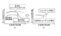
さらに、原稿サイズの判定におけるS/Nを向上させるために、シェーディング補正も有効である。図17は、比較例の画像読取装置が原稿サイズ検知時に行うシェーディング補正を例示する図である。なお、ADC出力データとは、イメージセンサが出力した結果をA/D変換するA/D変換器が出力したデータである。例えば、画像読取装置は、イメージセンサの感度や光源の光量などの不均一性、レンズのCOS4乗則による端部の光量落ち込みなどによる主走査方向の光量むらを、事前にシェーディングデータを取得して、読取画像との比を取ることによって補正する。 Furthermore, shading correction is also effective in order to improve the S / N in the determination of the document size. FIG. 17 is a diagram illustrating shading correction performed by the image reading apparatus of the comparative example at the time of document size detection. The ADC output data is data output from an A / D converter that A / D converts the result output from the image sensor. For example, the image reading apparatus acquires shading data in advance in the light amount unevenness in the main scanning direction due to the unevenness of the sensitivity of the image sensor, the light amount of the light source, etc. , Correct by taking the ratio to the read image.
図17(a)に示した比較例の画像読取装置は、原稿サイズ検知時に光源を全点灯させて取得したシェーディングデータを用いて補正を行っており、部分点灯時とは主走査方向の光量の均一性が異なる。そのため、図17(b)に示したように、比較例の画像読取装置が全点灯時のシェーディングデータを使用してシェーディング補正を行うと、光源の部分点灯の場合に最適なシェーディング補正を行うことができない。特に原稿端部の補正後出力データが落ち込んでしまう。画像読取装置は、原稿サイズを判定する場合、原稿端部のデータによって原稿の有無を判定しているので、端部の補正が正しく行われないと判定の精度が悪化し、原稿サイズの誤検知を招く。 In the image reading apparatus of the comparative example shown in FIG. 17A, correction is performed using shading data acquired by fully turning on the light source at the time of document size detection. The uniformity is different. Therefore, as shown in FIG. 17B, when the image reading apparatus of the comparative example performs shading correction using shading data when all lights are on, it performs optimum shading correction in the case of partial lighting of the light source. I can not In particular, the corrected output data at the end of the document drops. When the image reading apparatus determines the size of the document, the presence or absence of the document is determined based on the data of the document edge. Therefore, the accuracy of the determination is not correct if the edge is not correctly corrected. Cause.
図18は、実施形態にかかる画像読取装置100が光源40を部分点灯させて取得したシェーディングデータを用いて行うシェーディング補正を示す図である。画像読取装置100は、光源40を部分点灯させて画像読取後に基準白板110を読み取ることにより、原稿サイズ検知の動作を遅延させることなく、光源40の部分点灯状態でのシェーディングデータを取得する(図19参照)。画像読取装置100は、光源40の部分点灯によるシェーディングデータによって白シェーディング補正を行うことにより、原稿サイズの判定の精度が改善され、原稿サイズの誤検知を防ぐことができる。
FIG. 18 is a diagram showing shading correction performed by the
図19は、画像読取装置100が原稿サイズを判定する場合の白シェーディングデータの取得位置を示す図である。図19に示すように、画像読取装置100は、原稿サイズを判定する場合、サイズ検知位置A、又はサイズ検知位置Aからホームポジション側(図19では左側)へ第1キャリッジ106が移動するときに原稿の一部を読み取り、原稿のサイズを判定する。そして、画像読取装置100は、シェーディングデータ取得位置Bに第1キャリッジ106が達したときに基準白板110を読取って白シェーディングデータを取得する。
FIG. 19 is a diagram showing the acquisition position of the white shading data when the
よって、画像読取装置100は、原稿サイズの判定用の原稿読み取りとほぼ同タイミングで点灯範囲が同一の白シェーディングデータを取得できるため、精度のよい白シェーディング補正が可能である。また、画像読取装置100は、イメージセンサ50の固定パターンノイズを補正するために、外乱光が入らない基準白板110の下方に第1キャリッジ106が達したときに黒シェーディングデータを取得する。
Therefore, since the
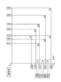
次に、イメージセンサ50についてさらに詳述する。図20は、イメージセンサ50の構成及びその周辺を示す図である。イメージセンサ50は、例えば主走査方向に配列された複数の画素500と、アナログ処理部510、パラレルシリアル変換部(パラ−シリ変換部)520、デジタル増幅部(D_gain)522、LVDS524及びタイミング制御部(TG)530を有するCMOSリニアセンサであり、CPU51の制御に応じて動作する。
Next, the
画素500それぞれは、光電変換を行うフォトダイオード501と、フォトダイオード501が発生させた電荷を転送させる回路等を有する。また、イメージセンサ50は、R,G,Bの色毎にそれぞれ一方向に配列された複数の画素500を備えていてもよい。
Each of the
アナログ処理部510は、複数のPGA(Programmable Gain Amplifier)512、及び複数のA/D変換器514を有し、画素500それぞれが出力するアナログ信号を増幅して、デジタル信号に変換し、パラレルシリアル変換部520に対してそれぞれ出力する。
The
パラレルシリアル変換部520は、アナログ処理部510が出力した各デジタル信号をパラレルシリアル変換し、デジタル増幅部522に対して出力する。デジタル増幅部522は、パラレルシリアル変換部520から入力された信号を増幅させ、LVDS524に対して出力する。LVDS524は、デジタル増幅部522から入力された信号を低電圧差動シリアル信号に変換し、後段に対して出力する。タイミング制御部530は、イメージセンサ50を構成する各部を制御する。
The parallel-
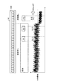
図21は、比較例の画像読取装置が有するイメージセンサにおけるCMOS特有の固定パターンノイズと画像信号のS/Nを示す図である。図21(a)に示すように、イメージセンサは、画素毎にオフセットが異なる固定パターンノイズがある。固定パターンノイズが補正されていない場合、図21(b)に示すように、画像信号にノイズが乗ったままとなり、原稿サイズを判定するための閾値を用いた判定精度が悪化してしまう。 FIG. 21 is a diagram showing fixed pattern noise peculiar to CMOS and S / N of an image signal in an image sensor included in an image reading apparatus of a comparative example. As shown in FIG. 21A, the image sensor has fixed pattern noise in which the offset is different for each pixel. When the fixed pattern noise is not corrected, as shown in FIG. 21B, the noise remains on the image signal, and the determination accuracy using the threshold for determining the document size is deteriorated.
図22は、画像読取装置100が有する第1補正部610の動作例を示す図である。第1補正部610は、CMOSイメージセンサ特有の固定パターンノイズを低減するために、原稿読取前に遮光状態の暗時画像を取得し、画素500毎に黒シェーディングデータ(基準黒レベル)として保持して、画素500毎に画像を読取った画像信号から黒シェーディングデータをそれぞれ減算する黒シェーディング補正を行う。
FIG. 22 is a diagram illustrating an operation example of the
図23は、第1補正部610の黒シェーディング補正による固定パターンノイズの軽減効果を示す図である。画像読取装置100は、第1補正部610が黒シェーディング補正を行うことにより、固定パターンノイズによる画素500毎のオフセット差を補正することができるので、図23に示したように原稿サイズの判定における画像信号のS/Nを改善することができる。
FIG. 23 is a diagram showing the reduction effect of fixed pattern noise by the black shading correction of the
11、51 CPU
40 光源
50 イメージセンサ
60 処理部
62 制御部
100 画像読取装置
110 基準白板
300 画像形成装置
305 作像部(画像形成部)
400−1,400−2 光源部材
402 発光部材(点光源:ブロック)
500 画素
602 周期拡張部
604 平均化部
606 判定部
608 補正処理部
610 第1補正部
612 第2補正部
11, 51 CPU
40
400-1, 400-2
500
Claims (10)
原稿サイズの判定を行う場合、原稿の読取りを行う場合よりも前記光源が照射する光量を低減させるよう制御する制御部と、
原稿サイズの判定を行う場合、原稿の読取りを行う場合よりも前記イメージセンサが主走査方向の光電変換を行う周期を拡張させる周期拡張部と、
原稿サイズの判定を行う場合、予め定められた複数の前記画素が光電変換した結果を平均化する平均化部と、
前記周期拡張部が拡張させた周期で前記平均化部が平均化した結果に応じて原稿サイズの判定を行う判定部と、
を有し、
前記周期拡張部は、
前記イメージセンサに対して予め定められた光量の外乱光が入射しても、前記イメージセンサの光電変換が飽和しないように、光電変換を行う周期を拡張させること
を特徴とする画像読取装置。 An image reading apparatus that performs determination of an original size and reading of an original according to a result of photoelectric conversion of an image sensor photoelectrically converting reflected light of light emitted to the original by a light source.
A control unit that performs control to reduce the amount of light emitted by the light source compared to the case of reading a document when the document size is determined;
When determining the size of a document, a cycle expansion unit that extends the cycle of performing photoelectric conversion in the main scanning direction by the image sensor as compared to when reading a document.
When determining the document size, an averaging unit that averages the results of photoelectric conversion of a plurality of predetermined pixels.
A determination unit that determines a document size according to a result of averaging by the averaging unit in a cycle expanded by the cycle expansion unit;
I have a,
The period expansion unit is
An image reading apparatus characterized by extending a period of performing photoelectric conversion so that photoelectric conversion of the image sensor is not saturated even when disturbance light having a predetermined light amount enters the image sensor .
前記平均化部は、
前記第1補正部が黒シェーディング補正を行った結果に基づいて、複数の前記画素が光電変換した結果を平均化する
を特徴とする請求項1に記載の画像読取装置。 The image sensor further includes a first correction unit that performs black shading correction using black shading data in the dark of the image sensor;
The averaging unit
The image reading apparatus according to claim 1, wherein results of photoelectric conversion of the plurality of pixels are averaged based on a result of performing the black shading correction by the first correction unit.
原稿サイズの判定を行う前に取得された暗時の黒シェーディングデータを用いて黒シェーディング補正を行うこと
を特徴とする請求項2に記載の画像読取装置。 The first correction unit is
3. The image reading apparatus according to claim 2 , wherein black shading correction is performed using black shading data in the dark acquired before determination of the document size.
前記周期拡張部が拡張させた周期で取得された暗時の黒シェーディングデータを用いて黒シェーディング補正を行うこと
を特徴とする請求項2又は3に記載の画像読取装置。 The first correction unit is
The image reading apparatus according to claim 2 or 3, characterized in that a black shading correction using the black shading data of dark that the periodic extensions are acquired at a period is extended.
点灯及び消灯をそれぞれ独立に制御可能にされた複数のブロックに分けられており、
前記制御部は、
原稿サイズの判定を行う場合に、原稿サイズの判定に不要な前記ブロックを消灯させるよう制御すること
を特徴とする請求項1乃至4のいずれか1項に記載の画像読取装置。 The light source is
The lighting and extinguishing are divided into a plurality of independently controlled blocks,
The control unit
The image reading apparatus according to any one of claims 1 to 4 , wherein, when determining the document size, control is performed to turn off the block unnecessary for determining the document size.
前記平均化部は、
前記第2補正部が白シェーディング補正を行った結果に基づいて、複数の前記画素が光電変換した結果を平均化すること
を特徴とする請求項1乃至5のいずれか1項に記載の画像読取装置。 The image sensor further includes a second correction unit that performs white shading correction using white shading data, which is a result of photoelectric conversion of the reflected light of the light emitted from the light source to the white reference member for each pixel.
The averaging unit
The image reading according to any one of claims 1 to 5 , wherein the results of photoelectric conversion of the plurality of pixels are averaged based on the result of the white correction performed by the second correction unit. apparatus.
原稿サイズの判定を行う前に取得された白シェーディングデータを用いて白シェーディング補正を行うこと
を特徴とする請求項6に記載の画像読取装置。 The second correction unit is
7. The image reading apparatus according to claim 6 , wherein white shading correction is performed using white shading data acquired before the determination of the document size.
原稿サイズの判定を行う場合、原稿の読取りを行う場合よりも前記光源が照射する光量を低減させるよう制御する制御部と、A control unit that performs control to reduce the amount of light emitted by the light source compared to the case of reading a document when the document size is determined;
原稿サイズの判定を行う場合、原稿の読取りを行う場合よりも前記イメージセンサが主走査方向の光電変換を行う周期を拡張させる周期拡張部と、When determining the size of a document, a cycle expansion unit that extends the cycle of performing photoelectric conversion in the main scanning direction by the image sensor as compared to when reading a document.
原稿サイズの判定を行う場合、予め定められた複数の前記画素が光電変換した結果を平均化する平均化部と、When determining the document size, an averaging unit that averages the results of photoelectric conversion of a plurality of predetermined pixels.
前記周期拡張部が拡張させた周期で前記平均化部が平均化した結果に応じて原稿サイズの判定を行う判定部と、A determination unit that determines a document size according to a result of averaging by the averaging unit in a cycle expanded by the cycle expansion unit;
を有し、Have
前記イメージセンサの暗時の黒シェーディングデータを用いて黒シェーディング補正を行う第1補正部をさらに有し、The image sensor further includes a first correction unit that performs black shading correction using black shading data in the dark of the image sensor;
前記平均化部は、The averaging unit
前記第1補正部が黒シェーディング補正を行った結果に基づいて、複数の前記画素が光電変換した結果を平均化し、Based on the result of black shading correction performed by the first correction unit, the results of photoelectric conversion of the plurality of pixels are averaged,
前記第1補正部は、The first correction unit is
前記周期拡張部が拡張させた周期で取得された暗時の黒シェーディングデータを用いて黒シェーディング補正を行うことPerforming black shading correction using black shading data in the dark acquired in the cycle expanded by the cycle expansion unit
を特徴とする画像読取装置。An image reading apparatus characterized by
原稿サイズの判定を行う前に取得された暗時の黒シェーディングデータを用いて黒シェーディング補正を行うことPerform black shading correction using black shading data in the dark acquired before determining the document size
を特徴とする請求項8に記載の画像読取装置。The image reading apparatus according to claim 8, characterized in that
前記画像読取装置が読取った画像データに基づく画像を形成する画像形成部と
を有することを特徴とする画像形成装置。 An image reading apparatus according to any one of claims 1 to 9 .
An image forming unit configured to form an image based on image data read by the image reading apparatus.
Priority Applications (2)
| Application Number | Priority Date | Filing Date | Title |
|---|---|---|---|
| JP2015139994A JP6536238B2 (en) | 2015-07-13 | 2015-07-13 | Image reading apparatus and image forming apparatus |
| US15/200,317 US9848097B2 (en) | 2015-07-13 | 2016-07-01 | Image reading device, image reading method, image forming apparatus, and computer-readable recording medium |
Applications Claiming Priority (1)
| Application Number | Priority Date | Filing Date | Title |
|---|---|---|---|
| JP2015139994A JP6536238B2 (en) | 2015-07-13 | 2015-07-13 | Image reading apparatus and image forming apparatus |
Publications (2)
| Publication Number | Publication Date |
|---|---|
| JP2017022614A JP2017022614A (en) | 2017-01-26 |
| JP6536238B2 true JP6536238B2 (en) | 2019-07-03 |
Family
ID=57775243
Family Applications (1)
| Application Number | Title | Priority Date | Filing Date |
|---|---|---|---|
| JP2015139994A Active JP6536238B2 (en) | 2015-07-13 | 2015-07-13 | Image reading apparatus and image forming apparatus |
Country Status (2)
| Country | Link |
|---|---|
| US (1) | US9848097B2 (en) |
| JP (1) | JP6536238B2 (en) |
Families Citing this family (10)
| Publication number | Priority date | Publication date | Assignee | Title |
|---|---|---|---|---|
| JP6699305B2 (en) | 2016-04-07 | 2020-05-27 | 株式会社リコー | Signal processing device, photoelectric conversion element, image reading device, image forming device, and signal processing method |
| JP2018129737A (en) * | 2017-02-10 | 2018-08-16 | 株式会社東芝 | Scanner for turning on light source during closing of pressure plate and detection program of sheet size by scanner |
| JP7115206B2 (en) * | 2018-10-11 | 2022-08-09 | 株式会社リコー | Document size detection device, image reading device, image forming device, and document size detection method |
| JP7183682B2 (en) | 2018-10-12 | 2022-12-06 | 株式会社リコー | Reading device, image reading device, image forming device, and reading method |
| JP7131287B2 (en) * | 2018-10-15 | 2022-09-06 | 株式会社リコー | Document size detection device, image reading device, image forming device, and document size detection method |
| JP7196644B2 (en) | 2019-01-30 | 2022-12-27 | 株式会社リコー | TILT DETECTION DEVICE, READING DEVICE, IMAGE PROCESSING DEVICE, AND TILT DETECTION METHOD |
| JP7131415B2 (en) | 2019-01-31 | 2022-09-06 | 株式会社リコー | TILT DETECTION DEVICE, READING DEVICE, IMAGE PROCESSING DEVICE, AND TILT DETECTION METHOD |
| JP7211238B2 (en) | 2019-04-16 | 2023-01-24 | 株式会社リコー | Edge detection device, tilt correction device, reading device, image processing device, and edge detection method |
| JP7287227B2 (en) | 2019-09-30 | 2023-06-06 | 株式会社リコー | Signal correction device, image reading device, image processing device, signal correction method and program |
| JP2022018303A (en) | 2020-07-15 | 2022-01-27 | 株式会社リコー | Information processing system, image forming apparatus, and method |
Family Cites Families (21)
| Publication number | Priority date | Publication date | Assignee | Title |
|---|---|---|---|---|
| JP3550589B2 (en) * | 1994-05-16 | 2004-08-04 | 株式会社ニコン | Image reading device |
| JP3453197B2 (en) | 1994-08-29 | 2003-10-06 | 株式会社リコー | Document size detector |
| JP2924751B2 (en) * | 1996-01-08 | 1999-07-26 | 富士ゼロックス株式会社 | Image reading device |
| US6952290B2 (en) * | 2000-03-30 | 2005-10-04 | Canon Kabushiki Kaisha | Sensing of original size |
| JP2002135534A (en) | 2000-10-20 | 2002-05-10 | Kyocera Mita Corp | Image reader and image forming device provided with the image reader |
| US6788438B2 (en) | 2000-04-27 | 2004-09-07 | Kyocera Mita Corporation | Image reading device and image forming apparatus comprising the same |
| JP4157832B2 (en) * | 2003-11-20 | 2008-10-01 | 株式会社リコー | Document size detection method, document reading apparatus, and image forming apparatus |
| JP3922379B2 (en) * | 2004-07-02 | 2007-05-30 | コニカミノルタビジネステクノロジーズ株式会社 | Image reading device |
| JP4721735B2 (en) * | 2005-03-15 | 2011-07-13 | 株式会社リコー | Document reading apparatus, image processing apparatus, image forming apparatus, and copying apparatus |
| JP4792926B2 (en) * | 2005-11-08 | 2011-10-12 | ブラザー工業株式会社 | Image reading device |
| JP4948360B2 (en) * | 2007-10-29 | 2012-06-06 | 株式会社リコー | Image reading apparatus and image forming apparatus |
| JP2009118129A (en) * | 2007-11-06 | 2009-05-28 | Murata Mach Ltd | Image reading apparatus |
| JP5473355B2 (en) * | 2008-03-18 | 2014-04-16 | キヤノン株式会社 | Document reader |
| JP2010041427A (en) | 2008-08-05 | 2010-02-18 | Ricoh Co Ltd | Image scanner, image forming apparatus, control method, control program, and recording medium |
| JP5316260B2 (en) * | 2009-02-27 | 2013-10-16 | 株式会社リコー | Document reading apparatus and size determination method |
| US8467110B2 (en) * | 2009-05-21 | 2013-06-18 | Kyocera Document Solutions Inc. | Image reading apparatus, image forming apparatus, and image reading method |
| JP5087590B2 (en) | 2009-05-22 | 2012-12-05 | 京セラドキュメントソリューションズ株式会社 | Image reading apparatus and image forming apparatus |
| JP5651566B2 (en) * | 2011-10-07 | 2015-01-14 | 京セラドキュメントソリューションズ株式会社 | Image reading apparatus and image forming apparatus |
| JP5974702B2 (en) * | 2012-07-19 | 2016-08-23 | 富士ゼロックス株式会社 | Image reading apparatus, image forming apparatus, and program |
| JP2014138301A (en) * | 2013-01-17 | 2014-07-28 | Ricoh Co Ltd | Document reading method, document reader, and image formation device |
| JP6012695B2 (en) * | 2014-11-25 | 2016-10-25 | 京セラドキュメントソリューションズ株式会社 | Image reading apparatus and image forming apparatus |
-
2015
- 2015-07-13 JP JP2015139994A patent/JP6536238B2/en active Active
-
2016
- 2016-07-01 US US15/200,317 patent/US9848097B2/en active Active
Also Published As
| Publication number | Publication date |
|---|---|
| US20170019547A1 (en) | 2017-01-19 |
| JP2017022614A (en) | 2017-01-26 |
| US9848097B2 (en) | 2017-12-19 |
Similar Documents
| Publication | Publication Date | Title |
|---|---|---|
| JP6536238B2 (en) | Image reading apparatus and image forming apparatus | |
| JP6383143B2 (en) | Imaging device, image reading apparatus, image forming apparatus, and imaging method | |
| US10182177B2 (en) | Signal processing device, image scanning device, image forming apparatus, and method of controlling the same | |
| JP7115206B2 (en) | Document size detection device, image reading device, image forming device, and document size detection method | |
| US10582092B2 (en) | Image reading apparatus with correction for sub-scanning color shifts, image forming apparatus, image reading method, and computer readable non-transitory storage medium | |
| JP7351124B2 (en) | Image processing device, image processing method and program | |
| JP7131287B2 (en) | Document size detection device, image reading device, image forming device, and document size detection method | |
| JP2007306078A (en) | Image reading apparatus and image reading method | |
| US6324375B1 (en) | Image forming apparatus for adjusting image forming condition and image forming condition adjusting method | |
| JP7400480B2 (en) | Image reading device and image reading method | |
| US9413919B2 (en) | Image reading device, image forming apparatus, and image reading method | |
| JP7043852B2 (en) | Position detectors, image forming devices, and methods | |
| JP7415585B2 (en) | Image processing device, reading device, image forming device, and image processing method | |
| JP6303504B2 (en) | Photoelectric conversion element, image reading apparatus, and image forming apparatus | |
| JP6477283B2 (en) | Photoelectric conversion element, image reading apparatus, image forming apparatus, and photoelectric conversion element control method | |
| JP2021093717A (en) | Image data processing apparatus, image reading device, image forming apparatus, and image data processing method | |
| JP6737365B2 (en) | Image sensor, image reading device, image forming device, and image reading method | |
| JP2014060631A (en) | Image reading device, image forming apparatus, and black level correction method | |
| JP2021022885A (en) | Reading device, image forming apparatus, and correction method | |
| JP6493500B2 (en) | Image sensor, image reading apparatus, image forming apparatus, and image reading method | |
| JP2021118537A (en) | Gain adjustment device, signal processing apparatus, imaging apparatus, image reading device, image forming apparatus, and gain adjustment method | |
| JP6610017B2 (en) | Image reading apparatus, image forming apparatus, and document size detection method | |
| JP6880936B2 (en) | Image reader, image forming device, and control method | |
| JP4401265B2 (en) | Image reading apparatus and image forming apparatus | |
| JP2023042893A (en) | Image processing apparatus, reading system, image formation system and feature amount detection method |
Legal Events
| Date | Code | Title | Description |
|---|---|---|---|
| A621 | Written request for application examination |
Free format text: JAPANESE INTERMEDIATE CODE: A621 Effective date: 20180214 |
|
| A977 | Report on retrieval |
Free format text: JAPANESE INTERMEDIATE CODE: A971007 Effective date: 20181015 |
|
| A131 | Notification of reasons for refusal |
Free format text: JAPANESE INTERMEDIATE CODE: A131 Effective date: 20181113 |
|
| A521 | Request for written amendment filed |
Free format text: JAPANESE INTERMEDIATE CODE: A523 Effective date: 20181227 |
|
| TRDD | Decision of grant or rejection written | ||
| A01 | Written decision to grant a patent or to grant a registration (utility model) |
Free format text: JAPANESE INTERMEDIATE CODE: A01 Effective date: 20190507 |
|
| A61 | First payment of annual fees (during grant procedure) |
Free format text: JAPANESE INTERMEDIATE CODE: A61 Effective date: 20190520 |
|
| R151 | Written notification of patent or utility model registration |
Ref document number: 6536238 Country of ref document: JP Free format text: JAPANESE INTERMEDIATE CODE: R151 |