JP6529671B2 - Locking prevention nut and fastening method - Google Patents
Locking prevention nut and fastening method Download PDFInfo
- Publication number
- JP6529671B2 JP6529671B2 JP2018520288A JP2018520288A JP6529671B2 JP 6529671 B2 JP6529671 B2 JP 6529671B2 JP 2018520288 A JP2018520288 A JP 2018520288A JP 2018520288 A JP2018520288 A JP 2018520288A JP 6529671 B2 JP6529671 B2 JP 6529671B2
- Authority
- JP
- Japan
- Prior art keywords
- hole
- thread
- loosening prevention
- diameter
- prevention nut
- Prior art date
- Legal status (The legal status is an assumption and is not a legal conclusion. Google has not performed a legal analysis and makes no representation as to the accuracy of the status listed.)
- Active
Links
- 230000002265 prevention Effects 0.000 title claims description 80
- 238000000034 method Methods 0.000 title claims description 13
- 230000013011 mating Effects 0.000 claims description 21
- 238000009751 slip forming Methods 0.000 claims description 4
- 230000007423 decrease Effects 0.000 claims description 3
- 230000002093 peripheral effect Effects 0.000 description 8
- 230000000694 effects Effects 0.000 description 2
- RKTYLMNFRDHKIL-UHFFFAOYSA-N copper;5,10,15,20-tetraphenylporphyrin-22,24-diide Chemical compound [Cu+2].C1=CC(C(=C2C=CC([N-]2)=C(C=2C=CC=CC=2)C=2C=CC(N=2)=C(C=2C=CC=CC=2)C2=CC=C3[N-]2)C=2C=CC=CC=2)=NC1=C3C1=CC=CC=C1 RKTYLMNFRDHKIL-UHFFFAOYSA-N 0.000 description 1
Images


Classifications
-
- F—MECHANICAL ENGINEERING; LIGHTING; HEATING; WEAPONS; BLASTING
- F16—ENGINEERING ELEMENTS AND UNITS; GENERAL MEASURES FOR PRODUCING AND MAINTAINING EFFECTIVE FUNCTIONING OF MACHINES OR INSTALLATIONS; THERMAL INSULATION IN GENERAL
- F16B—DEVICES FOR FASTENING OR SECURING CONSTRUCTIONAL ELEMENTS OR MACHINE PARTS TOGETHER, e.g. NAILS, BOLTS, CIRCLIPS, CLAMPS, CLIPS OR WEDGES; JOINTS OR JOINTING
- F16B39/00—Locking of screws, bolts or nuts
- F16B39/22—Locking of screws, bolts or nuts in which the locking takes place during screwing down or tightening
- F16B39/28—Locking of screws, bolts or nuts in which the locking takes place during screwing down or tightening by special members on, or shape of, the nut or bolt
- F16B39/30—Locking exclusively by special shape of the screw-thread
Landscapes
- Engineering & Computer Science (AREA)
- General Engineering & Computer Science (AREA)
- Mechanical Engineering (AREA)
- Bolts, Nuts, And Washers (AREA)
- Dowels (AREA)
Description
本発明は、ボルトなどの相手部材に締め付けられ、振動などで生じる戻り回転による緩みが防止される緩み防止ナットおよび締結方法に関する。 BACKGROUND OF THE INVENTION Field of the Invention The present invention relates to a loosening prevention nut and a fastening method, which are tightened on a mating member such as a bolt and prevented from loosening due to return rotation caused by vibration or the like.
従来、種々の建築部材あるいは機械部品を固定するために、締結部品としてボルトおよびナットが用いられる。締結部品として用いられるボルトおよびナットは、被締結部品の振動あるいは回転による滑りを起因としてナットが戻り方向に回転することがある。このため、ナットに戻り回転による緩みが発生し、締結効果の低下が問題となる。 Conventionally, bolts and nuts are used as fasteners to secure various building components or machine parts. In bolts and nuts used as fastening parts, the nuts may rotate in the return direction due to slippage due to vibration or rotation of the parts to be fastened. As a result, the nut returns and loosens due to rotation, which causes a problem of reduction in the fastening effect.
この戻り回転による緩みを防止するため、種々のボルトおよびナットの構造が提案されている(特許文献1、2参照)。 In order to prevent the looseness due to the return rotation, various bolt and nut structures have been proposed (see Patent Documents 1 and 2).
たとえば、特許文献1に記載の技術では、ナットをボルトに締め付ける際にナットの座面に形成した突起の先端がボルトの雄ネジ部へ食いつく。そして、雄ネジ部に食いついた突起が潰れて、ボルトの雄ネジ部へ巻き込まれる摩擦力の上昇で緩み止め効果が高められている。 For example, in the technique described in Patent Document 1, when the nut is tightened to a bolt, the tip of a projection formed on the bearing surface of the nut bites into the male screw portion of the bolt. And the protrusion which bited in the external thread part is crushed, and the locking effect is heightened by the rise of the frictional force taken in by the external thread part of a bolt.
また、特許文献2に記載の技術では、ナットの雌ネジ部の一部がボルトの雄ネジ部の破壊部により破壊される。これにより、ボルトにねじ込まれたナットが緩まない構造となっている。 Further, in the technique described in Patent Document 2, a part of the female screw part of the nut is broken by the broken part of the male screw part of the bolt. Thus, the nut screwed into the bolt does not come loose.
特許文献1に記載の技術では、ナットの一部が変形し、螺合するボルトに対する摩擦力の向上に寄与することで緩み防止を図っている。しかし、飽くまでも摩擦力の向上が手法として用いられている。このため、被締結部材が振動を受けることによるまたは被締結部材が回転するなどをした場合に、締結部の滑りを起因とした戻り回転による緩みが防止できない。 In the technique described in Patent Document 1, a part of the nut is deformed to contribute to the improvement of the frictional force with respect to the bolt to be screwed, thereby preventing the loosening. However, the improvement of the frictional force is used as a method until it gets tired. For this reason, when a to-be-fastened member receives a vibration, or when a to-be-fastened member rotates etc., the loosening by the return rotation which made the slip of a fastening part a cause can not be prevented.
特許文献2に記載の技術では、ボルトの雄ネジ部に破壊部を有し、ナットの雌ネジ部の一部を破壊することにより緩みを防止する。しかし、ボルトが雄ネジ部を有するナットの緩みを改善し得る構造ではない。 In the technique described in Patent Document 2, the external thread portion of the bolt has a breaking portion, and loosening is prevented by breaking a portion of the internal thread portion of the nut. However, the bolt is not a structure that can improve the loosening of a nut having an external thread.
本発明は、上記課題を解決するためのものであり、より強固にナットの戻り回転による緩みを防止する緩み防止ナットおよび締結方法を提供することを目的とする。 The present invention is intended to solve the above-mentioned problems, and it is an object of the present invention to provide a loosening preventing nut and a fastening method which more securely prevent loosening due to return rotation of the nut.
本発明に係る緩み防止ナットは、一方の端面に開口した開口部から連続し、相手部材の雄ネジ部に螺合する雌ネジ部と、他方の端面に開口した開口部から連続し、前記相手部材の雄ネジ部の雄ネジ外径よりも小径であり、かつ、雄ネジ谷径より大径である孔部と、を備え、前記相手部材に対して前記雌ネジ部側から取り付けられ、螺合される前記相手部材に対して締め付け回転する際に、前記相手部材の雄ネジ部のネジ山を前記孔部で塑性変形させるものである。 The loosening prevention nut according to the present invention is continuous from the opening opened at one end face, and is continuous from the female screw portion screwed with the external thread of the mating member and the opening opened at the other end face, A hole having a diameter smaller than the external diameter of the external thread of the external thread of the member and larger than the diameter of the external thread valley, and attached from the side of the internal thread to the mating member The screw thread of the male screw portion of the mating member is plastically deformed at the hole portion when it is tightened and rotated with respect to the mating member to be engaged .
本発明に係る締結方法は、一方の端面に開口した開口部から連続し、相手部材の雄ネジ部に螺合する雌ネジ部と、他方の端面に開口した開口部から連続し、前記相手部材の雄ネジ部の雄ネジ外径よりも小径であり、かつ、雄ネジ谷径より大径である孔部と、を備えた緩み防止ナットを、前記相手部材に対して前記雌ネジ部側から取り付け、螺合される前記相手部材に対して締め付け回転する際に、前記相手部材の雄ネジ部のネジ山を前記孔部で塑性変形させるものである。 In the fastening method according to the present invention, the mating member is continuous from the opening opened at one end face, and is continuous from the female screw portion screwed to the male screw portion of the mating member and the opening opened at the other end face And a hole having a diameter smaller than the external diameter of the external thread of the external thread and a diameter larger than the diameter of the external thread from the side of the internal thread relative to the counter member. The screw thread of the male screw portion of the mating member is plastically deformed at the hole when the screw is tightened and rotated with respect to the mating member to be attached and screwed.
本発明に係る緩み防止ナットおよび締結方法によれば、雌ネジ部と、孔部と、を備えた緩み防止ナットを、相手部材に対して雌ネジ部側から取り付け、螺合される相手部材に対して締め付け回転する際に、相手部材の雄ネジ部のネジ山を孔部で塑性変形させる。塑性変形した雄ネジ部は、緩み防止ナットの雌ネジ部に螺合しない。このため、緩み防止ナットは、塑性変形した雄ネジ部の後退方向に戻り回転しない。したがって、緩み防止ナットは、戻り回転による緩みがより強固に防止できる。 According to the loosening prevention nut and the fastening method of the present invention, the loosening prevention nut having the female screw portion and the hole portion is attached to the mating member from the female screw portion side, and is screwed onto the mating member At the time of tightening and rotating, the thread of the male screw of the mating member is plastically deformed at the hole. The plastically deformed external thread does not screw into the internal thread of the loosening prevention nut. For this reason, the loosening prevention nut does not rotate back in the backward direction of the plastically deformed external thread. Therefore, the loosening prevention nut can prevent the loosening due to the return rotation more firmly.
以下、図面に基づいて本発明の実施の形態について説明する。
なお、各図において、同一の符号を付したものは、同一のまたはこれに相当するものであり、これは明細書の全文において共通している。
さらに、明細書全文に示されている構成要素の形態は、あくまで例示であってこれらの記載に限定されるものではない。Hereinafter, embodiments of the present invention will be described based on the drawings.
In the drawings, the same reference numerals denote the same or corresponding parts, which are common to the whole text of the specification.
Furthermore, the form of the component shown in the specification full text is an illustration to the last, and is not limited to these descriptions.
実施の形態1.
本発明の実施の形態1に係る緩み防止ナット100について説明する。
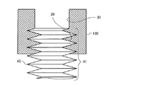
図1は、本発明の実施の形態1に係る緩み防止ナット100を示す断面図である。図2は、本発明の実施の形態1に係る緩み防止ナット100がボルト40に締め付けられる状態を示す図である。
図1に示す緩み防止ナット100は、雌ネジ部20と、孔部30と、を備えている。
緩み防止ナット100は、6角、8角あるいは4角などの一般的な外形形状である。Embodiment 1
A
FIG. 1 is a cross-sectional view showing a
The
The
図2に示すように、雌ネジ部20は、相手部材であるボルト40に取り付けられる側の一方の端面21に開口した開口部から連続し、ボルト40の雄ネジ部41に螺合する。雌ネジ部20には、所定のリード角およびピッチに従ったひっかかり高さのネジ山22が形成されている。
As shown in FIG. 2, the
孔部30は、ボルト40に取り付けられる側とは反対側の他方の端面31に開口した開口部から連続している。孔部30の孔径は、ボルト40の雄ネジ部41の雄ネジ外径42よりも小径であり、かつ、雄ネジ谷径43より大径である。
具体的には、孔部30は、ボルト40の雄ネジ部41のネジ山44を塑性変形させてボルト40の雄ネジ部41のネジ溝45が埋まり、外周面46となるボルト40の雄ネジ部41を雌ネジ部20の内径23よりも大径に構成する孔径である。
孔部30の孔径は、同一の中心線で軸方向に延びる同一な孔径寸法である。The
Specifically, the
The hole diameter of the
雌ネジ部20と孔部30とは、軸方向に延びる中心線が一致している。また、雌ネジ部20と孔部30とは、緩み防止ナット100の内部で直接的に連続して形成されている。
The
以上のような構成の緩み防止ナット100は、締め付け回転方向とは反対方向である後退方向に、雌ネジ部20に連続して孔部30を有する。孔部30は、緩み防止ナット100が締め付け回転方向に回転させられると、ボルト40の雄ネジ部41のネジ山44を潰して緩み防止ナット100の雌ネジ部20と螺合しない形に塑性変形させる。
緩み防止ナット100は、雌ネジ部20に連続して孔部30を有する。このため、緩み防止ナット100がユーザーによって冶具を用いて締め付け回転方向に回転させられるときに、孔部30がボルト40の雄ネジ部41のネジ山44を塑性変形させるために大きな力が必要である。しかし、ユーザーが大きな力でボルト40の雄ネジ部41のネジ山44を塑性変形させると、ボルト40の雄ネジ部41の塑性変形された箇所は、再度の変形がし難い。The
The
図3は、本発明の実施の形態1に係る緩み防止ナットの雌ネジ部がボルトの雄ネジ部に螺合する状態を示す図である。図4は、本発明の実施の形態1に係る緩み防止ナットの孔部がボルトの雄ネジ部を塑性変形させる状態を示す図である。 FIG. 3 is a view showing a state in which the female screw portion of the loosening prevention nut according to the first embodiment of the present invention is screwed to the male screw portion of the bolt. FIG. 4 is a view showing a state in which the hole portion of the loosening prevention nut according to the first embodiment of the present invention plastically deforms the male screw portion of the bolt.
まず、図2に示すように、被締結部材50の取付孔51を挿通して上向きに突出した雄ネジ部41を有するボルト40に対して、緩み防止ナット100の一方の端面21に開口した雌ネジ部20が螺合される。
First, as shown in FIG. 2, a female member opened at one
次に、緩み防止ナット100がユーザーによって冶具を用いて締め付け回転方向に回転させられ、被締結部材50側に進行する。図3に示すように、緩み防止ナット100がボルト40に螺合させられて行くと、緩み防止ナット100の孔部30がボルト40の雄ネジ部41の先端に接触する。
Next, the
緩み防止ナット100が更に締め付けられると、緩み防止ナット100の孔部30は塑性変形せずに締め付け回転方向に進もうとする。このとき、緩み防止ナット100の孔部30の孔径は、螺合されるボルト40の雄ネジ部41の雄ネジ外径42よりも小径である。このため、図4に示すように、孔部30は、ボルト40の雄ネジ部41のネジ山44をネジ溝45に埋め込む形で塑性変形させる。塑性変形したボルト40の雄ネジ部41の外周面46の外径は、緩み防止ナット100の孔部30の孔径とほぼ一致する。
When the
図5は、本発明の実施の形態1に係るボルト40の雄ネジ部41を示す一部展開図である。図6は、本発明の実施の形態1に係るボルト40の雄ネジ部41が塑性変形した境界47を示す一部展開図である。
FIG. 5 is a partially developed view showing the
図5に示すように、塑性変形前は、ボルト40の雄ネジ部41のネジ山44とネジ溝45とが緩み防止ナット100の雌ネジ部20に螺合できるように明確に分かれている。
As shown in FIG. 5, before plastic deformation, the
一方、図6に示すように、緩み防止ナット100が締め付け回転方向に進行し、孔部30がボルト40の雄ネジ部41のネジ山44を塑性変形させると、ボルト40の雄ネジ部41のネジ山44とネジ溝45とがほぼ一定の径寸法の外周面46になる。つまり、図4に示す図示矢印のように、緩み防止ナット100の孔部30が通過して塑性変形したボルト40の雄ネジ部41のネジ溝45は、塑性変形したネジ山44に埋められる。このため、緩み防止ナット100の雌ネジ部20は、塑性変形したボルト40の雄ネジ部41とは螺合できなくなる。
On the other hand, as shown in FIG. 6, when the
このように、緩み防止ナット100が締め付けられた後では、緩み防止ナット100の雌ネジ部20とボルト40の塑性変形された部位である外周面46は噛み合わない。このため、緩み防止ナット100は、ボルト40の締め付け回転方向とは反対方向へ戻り回転することができない。つまり、被締結部材50が振動を受けることによる、または回転するなどをした場合の締結部の滑りを受ける場合にも緩み防止ナット100は、戻り回転による緩みを起こさない。
Thus, after the
また、ボルト40の塑性変形された外周面46が戻り回転による緩み方向に変形しようとしても、ボルト40の塑性変形された部分がその境界47の箇所から連続している。そのため、緩み防止ナット100の戻り回転による緩みは、ボルト40の連続する塑性変形された外周面46によって強固に阻止される。あるいは、境界47から外周面46の一部が変形しても、外周面46がその部分から連続する。これにより、緩み防止ナット100の戻り回転による緩みは、最小限に制限される。したがって、緩み防止ナット100の戻り回転による緩みが悪化することが防止できる。
Further, even if the plastically deformed outer
実施の形態1によれば、緩み防止ナット100は、一方の端面21に開口した開口部から連続し、ボルト40の雄ネジ部41に螺合する雌ネジ部20を備えている。緩み防止ナット100は、他方の端面31に開口した開口部から連続し、ボルト40の雄ネジ部41の雄ネジ外径42よりも小径な孔部30を備えている。
この構成によれば、雌ネジ部20と、孔部30と、を備えた緩み防止ナット100を、ボルト40に対して雌ネジ部20側から取り付け、螺合されるボルト40に対して締め付け回転する際に、ボルト40の雄ネジ部41のネジ山44を孔部30で塑性変形させる。塑性変形した雄ネジ部41は、緩み防止ナット100の雌ネジ部20に螺合しない。このため、緩み防止ナット100は、塑性変形した雄ネジ部41の後退方向に戻り回転しない。したがって、緩み防止ナット100は、戻り回転による緩みがより強固に防止できる。According to the first embodiment, the loosening
According to this configuration, the loosening
雌ネジ部20と孔部30とは、中心線が一致している。
この構成によれば、緩み防止ナット100が螺合されるボルト40に対して締め付け回転する際に、ボルト40の雄ネジ部41のネジ山44を孔部30で塑性変形させることができる。The centerline of the
According to this configuration, when the
雌ネジ部20と孔部30とは、連続して形成されている。
この構成によれば、緩み防止ナット100がユーザーによって冶具を用いて締め付け回転方向に回転させられるときにボルト40の雄ネジ部41が孔部30に入っていくのに大きな力が必要である。しかし、ユーザーが大きな力でボルト40の雄ネジ部41のネジ山44を塑性変形させると、塑性変形された箇所は、再度の変形がし難い。したがって、緩み防止ナット100は、戻り回転による緩みがより強固に防止できる。The
According to this configuration, a large force is required for the
緩み防止ナット100は、ボルト40に対して雌ネジ部20側から取り付けられ、螺合されるボルト40に対して締め付け回転する際に、ボルト40の雄ネジ部41のネジ山44を孔部30で塑性変形させる。
この構成によれば、塑性変形した雄ネジ部41は、緩み防止ナット100の雌ネジ部20に螺合しない。このため、緩み防止ナット100は、塑性変形した雄ネジ部41の後退方向に戻り回転しない。したがって、緩み防止ナット100は、戻り回転による緩みがより強固に防止できる。The loosening
According to this configuration, the plastically deformed
孔部30は、ボルト40の雄ネジ部41のネジ山44を塑性変形させてボルト40の雄ネジ部41のネジ溝45が埋まり、ボルト40の雄ネジ部41を雌ネジ部20の内径23よりも大径に構成する孔径である。
この構成によれば、塑性変形した雄ネジ部41は、緩み防止ナット100の雌ネジ部20に螺合しない外周面46となった外径寸法に変形する。In the
According to this configuration, the plastically deformed
緩み防止ナット100は、一方の端面21に開口した開口部から連続し、ボルト40の雄ネジ部41に螺合する雌ネジ部20を備えている。緩み防止ナット100は、他方の端面31に開口した開口部から連続し、ボルト40の雄ネジ部41の雄ネジ外径42よりも小径な孔部30を備えている。締結方法は、緩み防止ナット100を、ボルト40に対して雌ネジ部20側から取り付ける。締結方法は、螺合されるボルト40に対して締め付け回転する際に、ボルト40の雄ネジ部41のネジ山44を孔部30で塑性変形させる。
この構成によれば、緩み防止ナット100は、ボルト40と螺合する雌ネジ部20を有する。このため、緩み防止ナット100は、緩み防止ナット100がボルト40に締め付けられる際に、締め付け回転方向である進行方向に回転できる。また、緩み防止ナット100は、雌ネジ部20に連続して孔部30を有する。そして、螺合されるボルト40に対して締め付け回転する際に、ボルト40の雄ネジ部41のネジ山44を孔部30で塑性変形させていく。そのため、ボルト40が緩み防止ナット100の雌ネジ部20と螺合しない形に塑性変形されている。よって、緩み防止ナット100は、戻り回転方向である後退方向に回転することができない。
特に、締結した建築部品の振動あるいは機械部品の回転を起因とする戻り回転しようとする力は、ボルト40の雄ネジ部41のネジ山44を孔部30で塑性変形させる力よりも弱い。このため、緩み防止ナット100は、戻り回転してボルト40の雄ネジ部41の外周面46を再度変形させることもない。したがって、緩み防止ナット100は、締結した建築部品の振動あるいは機械部品の回転を起因とする戻り回転による緩みがより強固に防止できる。The loosening
According to this configuration, the loosening
In particular, the force to return and rotate due to the vibration of the fastened building component or the rotation of the mechanical component is weaker than the force that plastically deforms the
実施の形態2.
図7は、本発明の実施の形態2に係る緩み防止ナット200を示す断面図である。実施の形態2では、実施の形態1と異なる点を中心に説明する。Second Embodiment
FIG. 7 is a cross-sectional view showing a
図7に示す緩み防止ナット200は、雌ネジ部20と、テーパ部60と、孔部30と、を備えている。
雌ネジ部20とテーパ部60と孔部30とは、軸方向に延びる中心線が一致している。
また、雌ネジ部20と孔部30とは、テーパ部60を介して連続して形成されている。The loosening
The
In addition, the
テーパ部60は、雌ネジ部20から孔部30に向かって径が小さくなる円すい台形状の内周面を有している。
なお、雌ネジ部20および孔部30は、実施の形態1と同様な構成である。The tapered
The
以上のような構成の緩み防止ナット200は、締め付け回転方向とは反対方向である後退方向に、雌ネジ部20に連続してテーパ部60を有している。緩み防止ナット100は、テーパ部60の最小孔径に連続して同一の孔径で軸方向に延びる孔部30を有する。テーパ部60は、緩み防止ナット100が締め付け回転方向に回転させられると、ボルト40の雄ネジ部41のネジ山44を緩み防止ナット100の雌ネジ部20と螺合しない形に徐々に潰して塑性変形させる。そして、最後に孔部30がボルト40の雄ネジ部41のネジ山44を孔部30の孔径まで塑性変形させる。
このため、緩み防止ナット200がユーザーによって冶具を用いて締め付け回転方向に回転させられるときの力が実施の形態1の緩み防止ナット100を回転させる場合よりも小さくて済む。The loosening
For this reason, the force when the
実施の形態2によれば、雌ネジ部20と孔部30とは、雌ネジ部20から孔部30に向かって径が小さくなるテーパ部60を介して連続して形成されている。
この構成によれば、テーパ部60を通過する際に、ボルト40の雄ネジ部41のネジ山44は、縮径する塑性変形を徐々に行う。このため、緩み防止ナット200がユーザーによって冶具を用いて締め付け回転方向に回転させられるときの力が小さくて済む。According to the second embodiment, the
According to this configuration, when passing through the tapered
20 雌ネジ部、21 端面、22 ネジ山、23 内径、30 孔部、31 端面、40 ボルト、41 雄ネジ部、42 雄ネジ外径、43 雄ネジ谷径、44 ネジ山、45 ネジ溝、46 外周面、47 境界、50 被締結部材、51 取付孔、60 テーパ部、100 緩み防止ナット、200 緩み防止ナット。 20 female screw part, 21 end face, 22 thread, 23 inner diameter, 30 hole part, 31 end face, 40 bolt, 41 male screw part, 42 male screw outer diameter, 43 male thread valley diameter, 44 thread, 45 thread groove, 46 outer circumferential surface, 47 boundary, 50 to-be-fastened member, 51 mounting hole, 60 taper portion, 100 loose lock nut, 200 loose lock nut.
Claims (6)
他方の端面に開口した開口部から連続し、前記相手部材の雄ネジ部の雄ネジ外径よりも小径であり、かつ、雄ネジ谷径より大径である孔部と、
を備え、
前記相手部材に対して前記雌ネジ部側から取り付けられ、螺合される前記相手部材に対して締め付け回転する際に、前記相手部材の雄ネジ部のネジ山を前記孔部で塑性変形させる緩み防止ナット。 A female screw portion which is continuous from the opening portion opened to one end face and which is screwed to the male screw portion of the mating member;
A hole which is continuous with an opening at the other end face and which has a diameter smaller than the external diameter of the external thread of the external thread of the mating member and which is larger than the diameter of the external thread valley;
Equipped with
A looseness which plastically deforms a screw thread of an external thread portion of the mating member when it is attached to the mating member from the female screw side and tightened and rotated with respect to the mating member to be screwed together Prevent nut.
Applications Claiming Priority (1)
| Application Number | Priority Date | Filing Date | Title |
|---|---|---|---|
| PCT/JP2016/066263 WO2017208401A1 (en) | 2016-06-01 | 2016-06-01 | Locking nut and fastening method |
Publications (2)
| Publication Number | Publication Date |
|---|---|
| JPWO2017208401A1 JPWO2017208401A1 (en) | 2018-12-20 |
| JP6529671B2 true JP6529671B2 (en) | 2019-06-12 |
Family
ID=60479240
Family Applications (1)
| Application Number | Title | Priority Date | Filing Date |
|---|---|---|---|
| JP2018520288A Active JP6529671B2 (en) | 2016-06-01 | 2016-06-01 | Locking prevention nut and fastening method |
Country Status (3)
| Country | Link |
|---|---|
| JP (1) | JP6529671B2 (en) |
| CN (1) | CN207064445U (en) |
| WO (1) | WO2017208401A1 (en) |
Families Citing this family (1)
| Publication number | Priority date | Publication date | Assignee | Title |
|---|---|---|---|---|
| JP7269841B2 (en) * | 2019-09-03 | 2023-05-09 | 株式会社竹中工務店 | Screw fixing method |
Family Cites Families (9)
| Publication number | Priority date | Publication date | Assignee | Title |
|---|---|---|---|---|
| JPS469138Y1 (en) * | 1967-07-25 | 1971-04-01 | ||
| JPS5923117A (en) * | 1982-07-30 | 1984-02-06 | 株式会社佐賀鉄工所 | Locking nut |
| JPS6286409U (en) * | 1985-11-19 | 1987-06-02 | ||
| JPH01166813U (en) * | 1988-04-28 | 1989-11-22 | ||
| JPH01166814U (en) * | 1988-04-30 | 1989-11-22 | ||
| JP3053251U (en) * | 1998-04-15 | 1998-10-23 | 株式会社 エクシオ | Glasses nut |
| JP2003166519A (en) * | 2001-12-03 | 2003-06-13 | Maruzen Byora:Kk | Plastic locking nut |
| WO2012166552A1 (en) * | 2011-06-02 | 2012-12-06 | A. Raymond Et Cie | Fasteners manufactured by three-dimensional printing |
| WO2015000317A1 (en) * | 2013-07-03 | 2015-01-08 | Xu Songlin | Anti-loosening cylindrical threaded part |
-
2016
- 2016-06-01 WO PCT/JP2016/066263 patent/WO2017208401A1/en active Application Filing
- 2016-06-01 JP JP2018520288A patent/JP6529671B2/en active Active
- 2016-06-01 CN CN201690000313.XU patent/CN207064445U/en active Active
Also Published As
| Publication number | Publication date |
|---|---|
| JPWO2017208401A1 (en) | 2018-12-20 |
| WO2017208401A1 (en) | 2017-12-07 |
| CN207064445U (en) | 2018-03-02 |
Similar Documents
| Publication | Publication Date | Title |
|---|---|---|
| EP3587842B1 (en) | Fastening structure | |
| JP6437313B2 (en) | Locking special double nut | |
| JP4276775B2 (en) | Screw member | |
| JPWO2012102401A1 (en) | Female thread structure | |
| US4067371A (en) | Mechanically locking fastener | |
| KR20160003315A (en) | Anti-loosening threaded part | |
| JP6757101B2 (en) | Loosening prevention fastening structure | |
| JP2013543962A (en) | Detent screw | |
| JP2015203492A (en) | Lock nut | |
| JP2018040376A (en) | Fastener | |
| JP6529671B2 (en) | Locking prevention nut and fastening method | |
| KR20150137910A (en) | Anti-loose bolt and nut | |
| JP2017141853A (en) | Method for manufacturing fastener comprising bolt and nut | |
| JP6427022B2 (en) | Locking nut | |
| JP2015145722A (en) | locking nut | |
| US20140314515A1 (en) | Threaded Component Locking Mechanism | |
| JP2012172780A (en) | Locking device for fastener | |
| JP4837963B2 (en) | Screw locking structure | |
| JP2006194291A (en) | Locking washer, failure detection device for oil lifter and fastening method | |
| JP2006022924A (en) | Loosening stopping screw | |
| JP3167659U (en) | Casing connection structure | |
| JP3194633U (en) | bolt | |
| JP2015227721A (en) | Looseness prevention structure for bolt and nut | |
| JP3232253U (en) | Grip nut | |
| JP6651244B2 (en) | Locking bolt set |
Legal Events
| Date | Code | Title | Description |
|---|---|---|---|
| A521 | Request for written amendment filed |
Free format text: JAPANESE INTERMEDIATE CODE: A523 Effective date: 20180827 |
|
| A621 | Written request for application examination |
Free format text: JAPANESE INTERMEDIATE CODE: A621 Effective date: 20180827 |
|
| TRDD | Decision of grant or rejection written | ||
| A01 | Written decision to grant a patent or to grant a registration (utility model) |
Free format text: JAPANESE INTERMEDIATE CODE: A01 Effective date: 20190416 |
|
| A61 | First payment of annual fees (during grant procedure) |
Free format text: JAPANESE INTERMEDIATE CODE: A61 Effective date: 20190514 |
|
| R150 | Certificate of patent or registration of utility model |
Ref document number: 6529671 Country of ref document: JP Free format text: JAPANESE INTERMEDIATE CODE: R150 |
|
| R250 | Receipt of annual fees |
Free format text: JAPANESE INTERMEDIATE CODE: R250 |
|
| R250 | Receipt of annual fees |
Free format text: JAPANESE INTERMEDIATE CODE: R250 |