JP6529332B2 - Electronic device and control method thereof - Google Patents

Electronic device and control method thereof Download PDF

Info

Publication number
JP6529332B2
JP6529332B2 JP2015098487A JP2015098487A JP6529332B2 JP 6529332 B2 JP6529332 B2 JP 6529332B2 JP 2015098487 A JP2015098487 A JP 2015098487A JP 2015098487 A JP2015098487 A JP 2015098487A JP 6529332 B2 JP6529332 B2 JP 6529332B2
Authority
JP
Japan
Prior art keywords
touch
area
inclination
electronic device
threshold
Prior art date
Legal status (The legal status is an assumption and is not a legal conclusion. Google has not performed a legal analysis and makes no representation as to the accuracy of the status listed.)
Expired - Fee Related
Application number
JP2015098487A
Other languages
Japanese (ja)
Other versions
JP2016212805A5 (en
JP2016212805A (en
Inventor
昭太郎 柳井
昭太郎 柳井
Current Assignee (The listed assignees may be inaccurate. Google has not performed a legal analysis and makes no representation or warranty as to the accuracy of the list.)
Canon Inc
Original Assignee
Canon Inc
Priority date (The priority date is an assumption and is not a legal conclusion. Google has not performed a legal analysis and makes no representation as to the accuracy of the date listed.)
Filing date
Publication date
Application filed by Canon Inc filed Critical Canon Inc
Priority to JP2015098487A priority Critical patent/JP6529332B2/en
Priority to US15/151,920 priority patent/US10108257B2/en
Publication of JP2016212805A publication Critical patent/JP2016212805A/en
Publication of JP2016212805A5 publication Critical patent/JP2016212805A5/ja
Application granted granted Critical
Publication of JP6529332B2 publication Critical patent/JP6529332B2/en
Expired - Fee Related legal-status Critical Current
Anticipated expiration legal-status Critical

Links

Images

Classifications

    • GPHYSICS
    • G06COMPUTING; CALCULATING OR COUNTING
    • G06FELECTRIC DIGITAL DATA PROCESSING
    • G06F3/00Input arrangements for transferring data to be processed into a form capable of being handled by the computer; Output arrangements for transferring data from processing unit to output unit, e.g. interface arrangements
    • G06F3/01Input arrangements or combined input and output arrangements for interaction between user and computer
    • G06F3/011Arrangements for interaction with the human body, e.g. for user immersion in virtual reality
    • GPHYSICS
    • G06COMPUTING; CALCULATING OR COUNTING
    • G06FELECTRIC DIGITAL DATA PROCESSING
    • G06F3/00Input arrangements for transferring data to be processed into a form capable of being handled by the computer; Output arrangements for transferring data from processing unit to output unit, e.g. interface arrangements
    • G06F3/002Specific input/output arrangements not covered by G06F3/01 - G06F3/16
    • G06F3/005Input arrangements through a video camera
    • GPHYSICS
    • G06COMPUTING; CALCULATING OR COUNTING
    • G06FELECTRIC DIGITAL DATA PROCESSING
    • G06F3/00Input arrangements for transferring data to be processed into a form capable of being handled by the computer; Output arrangements for transferring data from processing unit to output unit, e.g. interface arrangements
    • G06F3/01Input arrangements or combined input and output arrangements for interaction between user and computer
    • G06F3/03Arrangements for converting the position or the displacement of a member into a coded form
    • G06F3/041Digitisers, e.g. for touch screens or touch pads, characterised by the transducing means
    • G06F3/0416Control or interface arrangements specially adapted for digitisers
    • G06F3/0418Control or interface arrangements specially adapted for digitisers for error correction or compensation, e.g. based on parallax, calibration or alignment
    • GPHYSICS
    • G06COMPUTING; CALCULATING OR COUNTING
    • G06FELECTRIC DIGITAL DATA PROCESSING
    • G06F3/00Input arrangements for transferring data to be processed into a form capable of being handled by the computer; Output arrangements for transferring data from processing unit to output unit, e.g. interface arrangements
    • G06F3/01Input arrangements or combined input and output arrangements for interaction between user and computer
    • G06F3/03Arrangements for converting the position or the displacement of a member into a coded form
    • G06F3/041Digitisers, e.g. for touch screens or touch pads, characterised by the transducing means
    • G06F3/044Digitisers, e.g. for touch screens or touch pads, characterised by the transducing means by capacitive means
    • G06F3/0443Digitisers, e.g. for touch screens or touch pads, characterised by the transducing means by capacitive means using a single layer of sensing electrodes
    • GPHYSICS
    • G06COMPUTING; CALCULATING OR COUNTING
    • G06FELECTRIC DIGITAL DATA PROCESSING
    • G06F3/00Input arrangements for transferring data to be processed into a form capable of being handled by the computer; Output arrangements for transferring data from processing unit to output unit, e.g. interface arrangements
    • G06F3/01Input arrangements or combined input and output arrangements for interaction between user and computer
    • G06F3/03Arrangements for converting the position or the displacement of a member into a coded form
    • G06F3/041Digitisers, e.g. for touch screens or touch pads, characterised by the transducing means
    • G06F3/044Digitisers, e.g. for touch screens or touch pads, characterised by the transducing means by capacitive means
    • G06F3/0446Digitisers, e.g. for touch screens or touch pads, characterised by the transducing means by capacitive means using a grid-like structure of electrodes in at least two directions, e.g. using row and column electrodes
    • GPHYSICS
    • G06COMPUTING; CALCULATING OR COUNTING
    • G06FELECTRIC DIGITAL DATA PROCESSING
    • G06F3/00Input arrangements for transferring data to be processed into a form capable of being handled by the computer; Output arrangements for transferring data from processing unit to output unit, e.g. interface arrangements
    • G06F3/01Input arrangements or combined input and output arrangements for interaction between user and computer
    • G06F3/048Interaction techniques based on graphical user interfaces [GUI]
    • G06F3/0484Interaction techniques based on graphical user interfaces [GUI] for the control of specific functions or operations, e.g. selecting or manipulating an object, an image or a displayed text element, setting a parameter value or selecting a range
    • G06F3/04842Selection of displayed objects or displayed text elements
    • GPHYSICS
    • G06COMPUTING; CALCULATING OR COUNTING
    • G06FELECTRIC DIGITAL DATA PROCESSING
    • G06F3/00Input arrangements for transferring data to be processed into a form capable of being handled by the computer; Output arrangements for transferring data from processing unit to output unit, e.g. interface arrangements
    • G06F3/01Input arrangements or combined input and output arrangements for interaction between user and computer
    • G06F3/048Interaction techniques based on graphical user interfaces [GUI]
    • G06F3/0487Interaction techniques based on graphical user interfaces [GUI] using specific features provided by the input device, e.g. functions controlled by the rotation of a mouse with dual sensing arrangements, or of the nature of the input device, e.g. tap gestures based on pressure sensed by a digitiser
    • G06F3/0488Interaction techniques based on graphical user interfaces [GUI] using specific features provided by the input device, e.g. functions controlled by the rotation of a mouse with dual sensing arrangements, or of the nature of the input device, e.g. tap gestures based on pressure sensed by a digitiser using a touch-screen or digitiser, e.g. input of commands through traced gestures
    • G06F3/04883Interaction techniques based on graphical user interfaces [GUI] using specific features provided by the input device, e.g. functions controlled by the rotation of a mouse with dual sensing arrangements, or of the nature of the input device, e.g. tap gestures based on pressure sensed by a digitiser using a touch-screen or digitiser, e.g. input of commands through traced gestures for inputting data by handwriting, e.g. gesture or text
    • HELECTRICITY
    • H04ELECTRIC COMMUNICATION TECHNIQUE
    • H04NPICTORIAL COMMUNICATION, e.g. TELEVISION
    • H04N23/00Cameras or camera modules comprising electronic image sensors; Control thereof
    • H04N23/60Control of cameras or camera modules
    • HELECTRICITY
    • H04ELECTRIC COMMUNICATION TECHNIQUE
    • H04NPICTORIAL COMMUNICATION, e.g. TELEVISION
    • H04N23/00Cameras or camera modules comprising electronic image sensors; Control thereof
    • H04N23/60Control of cameras or camera modules
    • H04N23/62Control of parameters via user interfaces
    • HELECTRICITY
    • H04ELECTRIC COMMUNICATION TECHNIQUE
    • H04NPICTORIAL COMMUNICATION, e.g. TELEVISION
    • H04N23/00Cameras or camera modules comprising electronic image sensors; Control thereof
    • H04N23/60Control of cameras or camera modules
    • H04N23/68Control of cameras or camera modules for stable pick-up of the scene, e.g. compensating for camera body vibrations
    • H04N23/681Motion detection
    • H04N23/6811Motion detection based on the image signal
    • GPHYSICS
    • G06COMPUTING; CALCULATING OR COUNTING
    • G06FELECTRIC DIGITAL DATA PROCESSING
    • G06F1/00Details not covered by groups G06F3/00 - G06F13/00 and G06F21/00
    • G06F1/16Constructional details or arrangements
    • G06F1/1613Constructional details or arrangements for portable computers
    • G06F1/163Wearable computers, e.g. on a belt
    • GPHYSICS
    • G06COMPUTING; CALCULATING OR COUNTING
    • G06FELECTRIC DIGITAL DATA PROCESSING
    • G06F2200/00Indexing scheme relating to G06F1/04 - G06F1/32
    • G06F2200/16Indexing scheme relating to G06F1/16 - G06F1/18
    • G06F2200/163Indexing scheme relating to constructional details of the computer
    • G06F2200/1637Sensing arrangement for detection of housing movement or orientation, e.g. for controlling scrolling or cursor movement on the display of an handheld computer

Landscapes

  • Engineering & Computer Science (AREA)
  • Theoretical Computer Science (AREA)
  • General Engineering & Computer Science (AREA)
  • Human Computer Interaction (AREA)
  • Physics & Mathematics (AREA)
  • General Physics & Mathematics (AREA)
  • Multimedia (AREA)
  • Signal Processing (AREA)
  • Studio Devices (AREA)
  • User Interface Of Digital Computer (AREA)
  • Details Of Cameras Including Film Mechanisms (AREA)
  • Camera Bodies And Camera Details Or Accessories (AREA)

Description

本発明は、タッチ操作を検出する電子機器及びその制御方法に関し、特にユーザの意図しないタッチによる誤動作を減らすことができる制御技術に関する。   The present invention relates to an electronic device for detecting a touch operation and a control method thereof, and more particularly to a control technique capable of reducing a malfunction due to an unintended touch of a user.

タッチ操作を検出するタッチパネルを有する装置においては、ユーザの意図しないタッチであっても、そのタッチ操作を検出したことに応じて、意図しない機能が実行されてしまうことがある。ユーザの意図しないタッチによる操作の誤動作を防止する方法として、広い接触面積のタッチ操作(面接触)に応じては機能を実行しないようにするものがある。特許文献1には、タッチパネル中で所定以上の面積へのタッチ操作入力を検出した場合には、その入力を無効とすることが記載されている。また、特許文献2には、ユーザが装置を把持した際に、意図せずタッチしやすいタッチパネルの左右端部の所定の領域を対象エリアとして、対象エリアにおけるタッチ面積が閾値以上であれば、タッチパネル全体へのタッチ操作を無効とすることが開示されている。   In an apparatus having a touch panel that detects a touch operation, even if the touch is not intended by the user, an unintended function may be executed in response to the detection of the touch operation. As a method of preventing a malfunction of an operation due to a touch unintended by the user, there is a method of not executing a function in response to a touch operation (surface contact) with a wide contact area. Patent Document 1 describes that when a touch operation input to a predetermined area or more is detected in the touch panel, the input is invalidated. Further, according to Patent Document 2, when a user grips the device, a predetermined area on the left and right ends of the touch panel which is easy to touch unintentionally is a target area, and the touch area in the target area is equal to or greater than the threshold. It is disclosed to invalidate the touch operation to the whole.

特開2011−2891号公報JP, 2011-2891, A 特開2014−203183号公報JP, 2014-203183, A

ユーザの意図しないタッチが行われる場合の一例として、ユーザがデジタルカメラ等の装置を首や肩からぶら下げて持ち歩く場合がある。装置のタッチパネルの面がユーザに対して傾いている場合に、ユーザが装置を首や肩からぶら下げて歩くと、タッチパネル全体ではなく一部の領域に面接触しやすい。また、ユーザがタッチ操作を行っている際には装置を傾けていることが多い。特許文献1のように、タッチパネル全体を判定の対象の領域とすると、意図的なタッチ面積の大きいタッチ操作が行われた場合に、ユーザの意図した操作にも関わらず、面接触として検出してしまう可能性がある。一方で、ユーザが装置を首や肩からぶら下げて歩く際に、タッチパネルの面がユーザに対して平行である場合には、タッチパネルの中央領域が面接触しやすい。特許文献2のように、筐体を把持したときに接触しやすいタッチパネルの端領域を、面接触を検出するための領域とすると、ユーザの意図しないタッチであってもタッチパネルの中央領域に接触した意図しないタッチを面接触として検出できない可能性がある。   As an example of a case where a user's unintended touch is performed, the user may carry a device such as a digital camera by hanging it from the neck or shoulder. When the surface of the touch panel of the device is inclined with respect to the user, if the user hangs the device from the neck or shoulder and walks, it is likely to touch the partial surface of the touch panel instead of the entire touch panel. In addition, when the user is performing a touch operation, the device is often tilted. Assuming that the entire touch panel is the area to be determined as in Patent Document 1, when a touch operation with a large intentional touch area is performed, surface contact is detected regardless of the operation intended by the user. There is a possibility of On the other hand, when the user hangs the apparatus from the neck or shoulder and walks, if the surface of the touch panel is parallel to the user, the central region of the touch panel is likely to be in surface contact. As in Patent Document 2, assuming that the end region of the touch panel which is easy to touch when holding the housing is a region for detecting surface contact, even if the touch is not intended by the user, the center region of the touch panel is touched. Unintended touch may not be detected as surface contact.

本発明は、上記の課題に鑑み、ユーザの意図しないタッチによる誤動作を減らすことができる電子機器の提供を目的とする。   An object of the present invention is to provide an electronic device capable of reducing a malfunction due to a touch not intended by a user in view of the above-mentioned problems.

上記目的を達成するために、本発明の電子機器は、電子機器の重力方向の傾きを検出する姿勢検出手段と、タッチパネルへのタッチを検出するタッチ検出手段と、タッチ検出手段により検出したタッチに応じて、当該タッチに応じた機能を実行する機能実行手段と、タッチ検出手段により検出したタッチについて対象領域内のタッチ面積を算出し、対象領域内のタッチ面積が閾値以上であった場合にはタッチに応じた機能を実行せず、対象領域内のタッチ面積が閾値より小さかった場合には機能実行手段によりタッチに応じた機能を実行するように制御する制御手段と、を有し、制御手段は、姿勢検出手段によって検出された電子機器の重力方向の傾きに応じて、タッチ面積を算出するための対象領域を異ならせるように制御することを特徴とする。 In order to achieve the above object, the electronic device according to the present invention includes an attitude detection unit that detects an inclination of the electronic device in the direction of gravity, a touch detection unit that detects a touch on the touch panel, and a touch detected by the touch detection unit. Accordingly, the touch area in the target area is calculated for the function execution unit that executes the function according to the touch and the touch detected by the touch detection unit, and the touch area in the target area is equal to or greater than the threshold. Control means for performing control to execute a function according to the touch by the function execution means when the touch area in the target area is smaller than the threshold without executing the function according to the touch; Is characterized in that the target area for calculating the touch area is controlled to be different according to the inclination of the electronic device detected by the attitude detection means in the direction of gravity. To.

本発明によれば、ユーザの意図しないタッチによる誤動作を減らすことができる。   According to the present invention, it is possible to reduce malfunction due to a touch not intended by the user.

本実施形態の構成を適用可能な装置の一例としてのデジタルカメラの外観図An external view of a digital camera as an example of an apparatus to which the configuration of the present embodiment can be applied 本実施形態の構成を適用可能な装置の一例としてのデジタルカメラの構成例を示すブロック図A block diagram showing a configuration example of a digital camera as an example of an apparatus to which the configuration of the present embodiment can be applied 本実施形態のタッチ検出の処理を示すフローチャートFlow chart showing processing of touch detection of the present embodiment 本実施形態のタッチ検出に関する領域を示す図The figure which shows the field regarding touch detection of this execution form 本実施形態のタッチ検出に関する領域を示す図The figure which shows the field regarding touch detection of this execution form 本実施形態のタッチ検出に関する領域を示す図The figure which shows the field regarding touch detection of this execution form タッチ操作機能実行処理を示すフローチャートFlow chart showing touch operation function execution processing タッチ検出に関する装置の向きと領域を示す図Diagram showing device orientation and area for touch detection

以下、図面を参照して本発明の好適な実施形態を説明する。   Hereinafter, preferred embodiments of the present invention will be described with reference to the drawings.

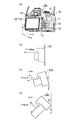
図1(a)〜(d)に本発明の撮像装置の一例としてのデジタルカメラ100の外観図を示す。図1(a)はデジタルカメラ100の背面斜視図(表示部28、タッチパネル70aのある側から見た図)、図1(b)〜図1(d)は横向きから見た外観図であり、背面の横側である側面側から見た外観図を示している。図1において、表示部28は画像や各種情報を表示する表示部であり、表示部28に重畳するようにタッチ操作を検出可能なタッチパネル70aがある。シャッターボタン61は撮影指示を行うための操作部である。電源スイッチ72はデジタルカメラ100の電源のON及びOFFを切り替える操作部材である。十字キー74の押した部分に応じた操作が可能である。SETボタン75は操作部70に含まれ、押しボタンであり、主に選択項目の決定などに用いられる。切替ボタン77は、タッチパネル70aへのタッチ操作を有効とするか、無効とするかを切り替える押しボタンである。ストラップ部76は紐等のストラップをつけるための部分(ストラップを装着可能な部分)であり、ストラップを首や肩に掛けてデジタルカメラ100を持ち運ぶとユーザは撮影機会を逃さずにすぐに撮影を行うことができる。また、デジタルカメラ100の方向軸であるX軸、Y軸、Z軸を図1(a)に示すように設定する。X軸とY軸は、タッチパネル70a及び表示部28の面と平行な方向であり、X軸は横方向、Y軸は縦方向の軸である。Z軸はタッチパネル70a及び表示部28の面と垂直な方向である。タッチパネル70a及び表示部28の面と重力方向が平行であり、図1(a)に示すZ軸が重力方向に対して垂直な方向にある場合を基準(z=0)とする。デジタルカメラ100が基準の状態から傾いた際のZ軸の水平方向(重力方向と垂直な方向)へ角度であり、表示部28(タッチパネル70a)の面の重力方向に対する角度を傾きとする。つまり、表示部28の面が重力方向と平行な場合は傾きz=0となり、重力方向にデジタルカメラ100が傾くほど傾きを示すzの値が大きくなる。図1(b)はデジタルカメラ100の傾きz=0の時、(c)は傾きz=αの時、(d)は傾きz=β(>α)の時を示しており、図1(b)の傾きz=0の時を基準として傾きが求められる。なお、デジタルカメラ100の傾きは後述する姿勢検知部55(姿勢検出)等によって検出可能である。ユーザがデジタルカメラ100にストラップをかけて持ち歩くと、ユーザの体や持ち物等に接触したことによりユーザの意図しないタッチであったとしてもタッチ検出され、対応する機能が実行されてしまう可能性がある。このようにデジタルカメラ100のタッチパネル70aをタッチ操作受付可能な状態で、ユーザ側に向けて持ち歩くと、ユーザが意図していなくてもタッチパネル70aにユーザの体やものが接触し、タッチ操作として検出される可能性がある。例えば、図1(b)のような状態で持ち歩くと、タッチパネル70aの面はユーザの体等に平行に接触しやすいため、タッチパネル70aの全面へのタッチ操作が検出されやすい。図1(c)や(d)のような状態で持ち歩くと、タッチパネル70aの面のうち下半分が上半分よりもユーザの体に近くなるため接触しやすく、また傾きの角度が大きいほどタッチパネル70aの下部分の領域(重力方向側)が接触しやすくなる。   FIGS. 1A to 1D show external views of a digital camera 100 as an example of an imaging device of the present invention. FIG. 1A is a rear perspective view of the digital camera 100 (a view from the side with the display unit 28 and the touch panel 70a), and FIGS. 1B to 1D are external views as viewed from the side, The external view seen from the side side which is a side by the side of the back is shown. In FIG. 1, a display unit 28 is a display unit that displays an image and various information, and includes a touch panel 70 a that can detect a touch operation so as to be superimposed on the display unit 28. A shutter button 61 is an operation unit for giving a photographing instruction. The power switch 72 is an operation member that switches power on and off of the digital camera 100. An operation according to the pressed portion of the cross key 74 is possible. The SET button 75 is included in the operation unit 70, is a push button, and is mainly used to determine selection items. The switching button 77 is a push button that switches whether the touch operation on the touch panel 70a is enabled or disabled. The strap portion 76 is a portion for attaching a strap or the like (a portion to which the strap can be attached), and when the digital camera 100 is carried by putting the strap on the neck and shoulders, the user immediately takes a picture without missing a photographing opportunity. It can be carried out. Further, X axis, Y axis, and Z axis which are directional axes of the digital camera 100 are set as shown in FIG. The X axis and the Y axis are directions parallel to the surfaces of the touch panel 70a and the display unit 28, the X axis is a horizontal direction, and the Y axis is a vertical axis. The Z axis is a direction perpendicular to the surfaces of the touch panel 70 a and the display unit 28. The case where the direction of gravity is parallel to the surfaces of the touch panel 70a and the display unit 28, and the Z axis shown in FIG. 1A is in the direction perpendicular to the direction of gravity is taken as a reference (z = 0). When the digital camera 100 is inclined from the reference state, an angle is in the horizontal direction (direction perpendicular to the direction of gravity) of the Z axis, and the angle with respect to the direction of gravity of the surface of the display unit 28 (touch panel 70a) is the inclination. That is, when the surface of the display unit 28 is parallel to the direction of gravity, the inclination z = 0, and the value of z indicating the inclination increases as the digital camera 100 inclines in the direction of gravity. 1B shows the case of the digital camera 100 when the inclination z = 0, FIG. 1C shows the case of the inclination z = α, and FIG. 1D shows the case of the inclination z = β (> α). The inclination is determined based on the inclination z of b). Note that the tilt of the digital camera 100 can be detected by a posture detection unit 55 (posture detection) or the like described later. When the user carries the strap around the digital camera 100, the touch may be detected even if the touch is not intended by the user due to contact with the user's body or belongings, and the corresponding function may be executed. . As described above, when the touch panel 70a of the digital camera 100 can be accepted for touch operation and carried around toward the user, the touch panel 70a touches the touch panel 70a even if the user does not intend it, and is detected as the touch operation There is a possibility. For example, when carried in the state as shown in FIG. 1B, the surface of the touch panel 70a is likely to be in parallel contact with the user's body or the like, so that the touch operation on the entire surface of the touch panel 70a is likely to be detected. When carried in the state as shown in FIG. 1 (c) or (d), the lower half of the surface of the touch panel 70a is closer to the user's body than the upper half, so it is easier to touch. Region of the lower part (gravity direction side) becomes easy to touch.

図2は、本実施形態によるデジタルカメラ100の構成例を示すブロック図である。図2(a)は装着されたレンズユニット150とデジタルカメラ100全体、(b)はタッチパネル70aの構成例を示すブロック図である。   FIG. 2 is a block diagram showing a configuration example of the digital camera 100 according to the present embodiment. FIG. 2A is a block diagram showing an example of the configuration of the lens unit 150 and the entire digital camera 100 mounted, and FIG. 2B is a configuration of the touch panel 70a.

レンズユニット150は、交換可能な撮影レンズを搭載するレンズユニットである。レンズユニット150は、レンズの大きさや枚数に応じてその重さや大きさが異なり、またズームを伸ばしたり縮めたりすることで長さが変わる。   The lens unit 150 is a lens unit on which an interchangeable imaging lens is mounted. The lens unit 150 varies in weight and size depending on the size and number of lenses, and changes in length by extending or contracting the zoom.

レンズ103は通常、複数枚のレンズから構成されるが、ここでは簡略して一枚のレンズのみで示している。通信端子6はレンズユニット150がデジタルカメラ100側と通信を行う為の通信端子であり、通信端子10はデジタルカメラ100がレンズユニット150側と通信を行う為の通信端子である。このように通信端子6、10を介してレンズ情報をデジタルカメラ100側に伝えることができる。また、レンズユニット150は、この通信端子6,10を介してシステム制御部50と通信し、内部のレンズシステム制御回路4によってレンズ103の位置を変位させることで焦点を合わせる。このレンズ位置の変位に応じてレンズユニット150の長さは変わる。   The lens 103 is usually composed of a plurality of lenses, but here, in a simplified manner, only one lens is shown. The communication terminal 6 is a communication terminal for the lens unit 150 to communicate with the digital camera 100 side, and the communication terminal 10 is a communication terminal for the digital camera 100 to communicate with the lens unit 150 side. As described above, lens information can be transmitted to the digital camera 100 via the communication terminals 6 and 10. Further, the lens unit 150 communicates with the system control unit 50 via the communication terminals 6 and 10, and the lens system control circuit 4 inside the lens unit 150 shifts the position of the lens 103 to focus. The length of the lens unit 150 changes according to the displacement of the lens position.

メモリ32は、デジタルデータに変換された画像データや、表示部28に表示するための画像データを格納する。また、所定枚数の静止画像や所定時間の動画像および音声を格納するのに十分な記憶容量を備えている。   The memory 32 stores image data converted into digital data and image data to be displayed on the display unit 28. In addition, it has a sufficient storage capacity for storing a predetermined number of still images and moving images and sounds for a predetermined time.

表示部28は画像を表示するための背面モニタであり、デジタルカメラ100の背面に設けられている。画像を表示するディスプレイであれば液晶方式に限らず、有機ELなど他の方式のディスプレイであってもよい。   The display unit 28 is a back monitor for displaying an image, and is provided on the back of the digital camera 100. If it is a display which displays an image, it will not be a liquid crystal system, and may be a display of other systems, such as organic EL.

不揮発性メモリ56は、電気的に消去・記録可能なメモリであり、例えばEEPROM等が用いられる。不揮発性メモリ56には、システム制御部50の動作用の定数、プログラム等が記憶される。ここでいう、プログラムとは、本実施形態にて後述する各種フローチャートを実行するためのプログラムのことである。   The non-volatile memory 56 is an electrically erasable / recordable memory, and for example, an EEPROM or the like is used. In the non-volatile memory 56, constants, programs and the like for operation of the system control unit 50 are stored. The program referred to here is a program for executing various flowcharts to be described later in the present embodiment.

システム制御部50は、デジタルカメラ100全体を制御する。前述した不揮発性メモリ56に記録されたプログラムを実行することで、後述する本実施形態の各処理を実現する。   The system control unit 50 controls the entire digital camera 100. By executing the program stored in the non-volatile memory 56 described above, each process of the present embodiment described later is realized.

システムメモリ52には、システム制御部50の動作用の定数、変数、不揮発性メモリ56から読み出したプログラム等を展開し、RAM等が用いられる。また、システム制御部はメモリ32、表示部28等を制御することにより表示制御も行う。   In the system memory 52, constants and variables for operation of the system control unit 50, programs etc. read out from the non-volatile memory 56 are expanded, and a RAM etc. is used. The system control unit also performs display control by controlling the memory 32, the display unit 28, and the like.

システムタイマー53は各種制御に用いる時間や、内蔵された時計の時間を計測する計時部である。   A system timer 53 is a clock unit that measures time used for various controls and time of a built-in clock.

第1シャッタースイッチ62、第2シャッタースイッチ64、操作部70はシステム制御部50に各種の動作指示を入力するための操作手段である。   The first shutter switch 62, the second shutter switch 64, and the operation unit 70 are operation means for inputting various operation instructions to the system control unit 50.

姿勢検知部55は重力方向に対するデジタルカメラ100の姿勢(傾き)を検知する。姿勢検知部55で検知された姿勢に基づいて、撮像部22で撮影された画像が、デジタルカメラ100を横に構えて撮影された画像であるか、縦に構えて撮影された画像なのかを判別可能である。システム制御部50は、姿勢検知部55で検知された姿勢に応じた向き情報を撮像部で撮像された画像の画像ファイルに付加したり、画像を回転して記録することが可能である。姿勢検知部55としては、加速度センサやジャイロセンサーなどを用いることができる。また、後述するように検知された傾きに応じて、システム制御部50は、タッチパネル70aでのタッチ検出の閾値や条件等についても設定することができる。   The posture detection unit 55 detects the posture (inclination) of the digital camera 100 with respect to the direction of gravity. Based on the posture detected by the posture detection unit 55, whether the image photographed by the imaging unit 22 is an image photographed by holding the digital camera 100 horizontally or an image photographed by holding the digital camera 100 vertically It can be determined. The system control unit 50 can add orientation information according to the posture detected by the posture detection unit 55 to an image file of an image captured by the imaging unit, or can rotate and record the image. As the posture detection unit 55, an acceleration sensor, a gyro sensor, or the like can be used. Further, according to the inclination detected as described later, the system control unit 50 can also set a threshold, a condition, and the like of touch detection on the touch panel 70a.

第1シャッタースイッチ62は、デジタルカメラ100に設けられたシャッターボタン61の操作途中、いわゆる半押し(撮影準備指示)でONとなり第1シャッタースイッチ信号SW1を発生する。第2シャッタースイッチ64は、シャッターボタン61の操作完了、いわゆる全押し(撮影指示)でONとなり、第2シャッタースイッチ信号SW2を発生する。システム制御部50は、第2シャッタースイッチ信号SW2により、撮像部からの信号読み出しから記録媒体200に画像データを書き込むまでの一連の撮影処理の動作を開始する。操作部70の各操作部材は、表示部28に表示される種々の機能アイコンを選択操作することなどにより、場面ごとに適宜機能が割り当てられ、各種機能ボタンとして作用する。機能ボタンとしては、例えば終了ボタン、戻るボタン、画像送りボタン、ジャンプボタン、絞込みボタン、属性変更ボタン等がある。例えば、メニューボタンが押されると各種の設定可能なメニュー画面が表示部28に表示される。利用者は、表示部28に表示されたメニュー画面と、上下左右の4方向ボタンである十字きー74やSETボタンとを用いて直感的に各種設定を行うことができる。   During the operation of the shutter button 61 provided to the digital camera 100, the first shutter switch 62 is turned on by a so-called half depression (shooting preparation instruction) and generates a first shutter switch signal SW1. The second shutter switch 64 is turned on by completion of the operation of the shutter button 61, that is, full-press (shooting instruction), and generates a second shutter switch signal SW2. The system control unit 50 starts a series of photographing processing operations from the signal reading from the imaging unit to the writing of the image data to the recording medium 200 by the second shutter switch signal SW2. Each operation member of the operation unit 70 is appropriately assigned a function for each scene by selecting and operating various function icons displayed on the display unit 28, and functions as various function buttons. The function buttons include, for example, an end button, a back button, an image feed button, a jump button, a narrowing button, and an attribute change button. For example, when the menu button is pressed, various settable menu screens are displayed on the display unit 28. The user can intuitively perform various settings using the menu screen displayed on the display unit 28 and the cross key 74 and the SET button which are four-way buttons up, down, left, and right.

操作部70は、ユーザからの操作を受け付ける入力部としての各種操作部材である。操作部70には、少なくとも以下のシャッターボタン61、電源スイッチ72、十字キー74、SETボタン75、切替ボタン77、タッチパネル70aの操作部が含まれる。   The operation unit 70 is various operation members as an input unit that receives an operation from a user. The operation unit 70 includes at least the following operation units of the shutter button 61, the power switch 72, the cross key 74, the SET button 75, the switching button 77, and the touch panel 70a.

電源制御部80は、電池検出回路、DC−DCコンバータ、通電するブロックを切り替えるスイッチ回路等により構成され、電池の装着の有無、電池の種類、電池残量の検出を行う。また、電源制御部80は、その検出結果及びシステム制御部50の指示に基づいてDC−DCコンバータを制御し、必要な電圧を必要な期間、記録媒体200を含む各部へ供給する。   The power supply control unit 80 includes a battery detection circuit, a DC-DC converter, a switch circuit for switching a block to be energized, and the like, and detects the presence or absence of a battery, the type of battery, and the battery remaining amount. Further, the power control unit 80 controls the DC-DC converter based on the detection result and an instruction of the system control unit 50, and supplies necessary voltages to the respective units including the recording medium 200 for a necessary period.

電源部30は、アルカリ電池やリチウム電池等の一次電池やNiCd電池やNiMH電池、Li電池等の二次電池、ACアダプター等からなる。   The power supply unit 30 includes a primary battery such as an alkaline battery or a lithium battery, a secondary battery such as a NiCd battery, a NiMH battery, or a Li battery, an AC adapter, or the like.

記録媒体I/F18は、メモリカードやハードディスク等の記録媒体200とのインターフェースである。記録媒体200は、撮影された画像を記録するためのメモリカード等の記録媒体であり、半導体メモリや磁気ディスク等から構成される。   The recording medium I / F 18 is an interface with the recording medium 200 such as a memory card or a hard disk. The recording medium 200 is a recording medium such as a memory card for recording a photographed image, and is formed of a semiconductor memory, a magnetic disk, or the like.

上述したようにデジタルカメラ100は、操作部70の一つとして、表示部28に対する接触を検知可能なタッチパネル70aを有する。タッチパネルと表示部28とは一体的に構成することができる。例えば、タッチパネルを光の透過率が表示部28の表示を妨げないように構成し、表示部28の表示面の上層に取り付ける。そして、タッチパネルにおける入力座標と、表示部28上の表示座標とを対応付ける。これにより、恰もユーザが表示部28上に表示された画面を直接的に操作可能であるかのようなGUI(グラフィカルユーザーインターフェース)を構成することができる。システム制御部50はタッチパネルへの以下の操作、あるいは状態を検出できる。   As described above, the digital camera 100 includes, as one of the operation units 70, the touch panel 70a capable of detecting a touch on the display unit 28. The touch panel and the display unit 28 can be integrally configured. For example, the touch panel is configured such that the light transmittance does not interfere with the display of the display unit 28, and the touch panel is attached to the upper layer of the display surface of the display unit 28. Then, the input coordinates on the touch panel are associated with the display coordinates on the display unit 28. As a result, it is possible to configure a GUI (Graphical User Interface) as if the user can directly operate the screen displayed on the display unit 28. The system control unit 50 can detect the following operation or state on the touch panel.

・タッチパネルにタッチしていなかった指やペンが新たにタッチパネルにタッチしたこと。すなわち、タッチの開始(以下、タッチダウン(Touch−Down)と称する)。
・タッチパネルを指やペンでタッチしている状態であること(以下、タッチオン(Touch−On)と称する)。
・タッチパネルを指やペンでタッチしたまま移動していること(以下、タッチムーブ(Touch−Move)と称する)。
・タッチパネルへタッチしていた指やペンを離したこと。すなわち、タッチの終了(以下、タッチアップ(Touch−Up)と称する)。
・タッチパネルに何もタッチしていない状態(以下、タッチオフ(Touch−Off)と称する)。
・ A finger or pen that did not touch the touch panel newly touched the touch panel. That is, the start of touch (hereinafter referred to as touch-down).
The touch panel is in a state of being touched with a finger or a pen (hereinafter referred to as touch-on).
-Moving while touching the touch panel with a finger or a pen (hereinafter, referred to as Touch-Move).
-Release the finger or pen that was touching the touch panel. That is, the end of the touch (hereinafter referred to as touch-up).
A state in which nothing is touched on the touch panel (hereinafter referred to as touch-off).

タッチダウンが検出されると、同時にタッチオンであることも検出される。タッチダウンの後、タッチアップが検出されない限りは、通常はタッチオンが検出され続ける。タッチムーブが検出されるのもタッチオンが検出されている状態である。タッチオンが検出されていても、タッチ位置が移動していなければタッチムーブは検出されない。タッチしていた全ての指やペンがタッチアップしたことが検出された後は、タッチオフとなる。   When touch down is detected, touch on is also detected at the same time. After touch down, touch on normally continues to be detected unless touch up is detected. The touch move is also detected in the state where the touch on is detected. Even if the touch on is detected, if the touch position is not moved, the touch move is not detected. After it is detected that all the fingers and pens that have been touched touch up, the touch is off.

これらの操作・状態や、タッチパネル上に指やペンがタッチしている位置座標は内部バスを通じてシステム制御部50に通知され、システム制御部50は通知された情報に基づいてタッチパネル上にどのような操作が行なわれたかを判定する。タッチパネルは、抵抗膜方式や静電容量方式、表面弾性波方式、赤外線方式、電磁誘導方式、画像認識方式、光センサ方式等、様々な方式のタッチパネルのうちいずれの方式のものを用いても良い。方式によって、タッチパネルに対する接触があったことでタッチがあったと検出する方式や、タッチパネルに対する指やペンの接近があったことでタッチがあったと検出する方式ものがあるが、いずれの方式でもよい。   The system control unit 50 is notified of these operations / states and position coordinates where a finger or pen is touching on the touch panel through the internal bus, and the system control unit 50 determines what kind of on the touch panel based on the notified information. Determine if the operation has been performed. The touch panel may be any of various touch panels such as resistive film type, capacitive type, surface acoustic wave type, infrared type, electromagnetic induction type, image recognition type, optical sensor type, etc. . Depending on the method, there is a method of detecting that there is a touch when there is a touch on the touch panel, and a method of detecting that there is a touch when there is a finger or pen approaching the touch panel, any method may be used.

次に、図2(b)のタッチパネル70aのブロック図により、タッチパネル70aの構成について説明する。   Next, the configuration of the touch panel 70a will be described with reference to the block diagram of the touch panel 70a of FIG. 2B.

タッチパネルの制御回路21は、外部クロック入力或いは内部発振回路を源振として、クロック信号を生成するためのPLL(Phase Locked Loop)回路を内蔵している。PLL回路により、1スキャンの周期或いは1サブスキャンの周期を変更することが可能である。   The control circuit 21 of the touch panel incorporates a PLL (Phase Locked Loop) circuit for generating a clock signal using an external clock input or an internal oscillation circuit as a source oscillation. The PLL circuit can change the cycle of one scan or the cycle of one subscan.

走査線駆動回路11及び検出信号処理回路12は、制御回路21により供給されるクロック信号により駆動される。制御回路21は検出信号処理回路12により出力された各電極の検出信号値が、任意のタッチ判定の閾値を超えているか否かを検出し、超えていればタッチ検出フラグをつけて、データをセンサメモリ13に順次転送する。1フレームのスキャンが完了すると、センサメモリ13に格納された1フレームの検出データから、タッチ検出領域のグルーピング、及びタッチ位置の重心演算を行い、タッチ検出数と、タッチ検出座標を算出する。1フレームのスキャンには、2ms(ミリ秒)等の所定時間かけて行われるので、スキャンの時間内(所定時間内)に検出されたタッチ点の総計(合計)がタッチ面積となる。   The scanning line drive circuit 11 and the detection signal processing circuit 12 are driven by a clock signal supplied by the control circuit 21. The control circuit 21 detects whether or not the detection signal value of each electrode output by the detection signal processing circuit 12 exceeds an arbitrary touch determination threshold value, and if it exceeds the touch detection flag, the data is The data is sequentially transferred to the sensor memory 13. When scanning of one frame is completed, grouping of touch detection areas and centroid calculation of touch positions are performed from detection data of one frame stored in the sensor memory 13 to calculate the number of touch detections and touch detection coordinates. Since scanning of one frame is performed over a predetermined time such as 2 ms (milliseconds), the total (total) of touch points detected within the scanning time (within the predetermined time) is the touch area.

また、1フレームのスキャンで、予め設定されたタッチパネル面上の所定の領域内でタッチ検出された交点数(センサ交点数)が所定数以上あった場合は、所定以上の面積を持った面での接触(面接触)と判定することが可能である。面接触の検出を行う領域や、面接触と判定するための交点数の条件はタッチパネルの制御回路21がシステム制御部50からの指令により、任意に変更することが可能である。   In addition, if the number of intersections (the number of sensor intersections) detected by touch in a predetermined area on the touch panel surface set in advance for one frame scan is more than a predetermined number, a surface with a predetermined area or more It can be determined that the contact (surface contact) of The control circuit 21 of the touch panel can arbitrarily change the area for detecting the surface contact and the condition of the number of intersection points for determining the surface contact according to a command from the system control unit 50.

タッチパネル70aは、静電容量方式のタッチパネルであり、列配列された複数の列電極と、行配列された複数の行電極が直交した電極を形成する。この直交する電極の行電極を走査線とし、列電極を読出線として使用する。行電極は、表示部28のコモン駆動信号VCOMを印加するための電極と共通となっている。このコモン駆動信号VCOMは、不図示の画素電極に印加される画素電圧とともに各画素の表示電圧を決定する。このため、行電極部は表示部28のTFT基板上に形成されている。一方で、列電極部は、表示部28の不図示のカラーフィルタガラス基板板上に形成される。図2(b)に示すように、本実施形態では、行電極はY0〜Y8の9つ、列電極はX0〜X12の13つずつ並んでいるものとして、Y軸方向の範囲をY0〜Y8、X軸方向の範囲をX0〜X12としてタッチパネル70aの範囲を説明する。   The touch panel 70a is a capacitive touch panel, and forms an electrode in which a plurality of column electrodes arranged in a row and a plurality of row electrodes arranged in a row are orthogonal to each other. The row electrodes of the orthogonal electrodes are used as scanning lines, and the column electrodes are used as reading lines. The row electrode is common to the electrode for applying the common drive signal VCOM of the display unit 28. The common drive signal VCOM determines the display voltage of each pixel together with the pixel voltage applied to the pixel electrode (not shown). For this reason, the row electrode portion is formed on the TFT substrate of the display portion 28. On the other hand, the column electrode portion is formed on a color filter glass substrate plate (not shown) of the display portion 28. As shown in FIG. 2B, in the present embodiment, it is assumed that the row electrodes are arranged in nine rows of Y0 to Y8 and the column electrodes are arranged in thirteen rows of X0 to X12, and the range in the Y axis direction is Y0 to Y8. The range of the touch panel 70a will be described by setting the range in the X axis direction as X0 to X12.

図2(b)の右側にはタッチパネル70aの電極の交点部Aの拡大図を示す。行電極15は定電流回路17に接続され、列電極14は所定の電位に固定される。定電流回路17により微弱な電流が流されると、列電極14及び行電極15間に発生する相互容量16に電荷が蓄積される。1交点当たり複数回の蓄積を実施するサブスキャンを行い、積分回路20にて積分を行う。1交点の測定(1スキャン)の結果は、A/Dコンバータ19によりデジタル信号に変換される。この検出信号値の変化量を静電容量変化量Cとして測定することでタッチ検出の有無を判定することが可能である。なお、本実施形態では静電容量によってタッチ操作およびタッチ面積を検出する方法を用いて説明するが、静電容量方式に限らず他の方式であっても本実施形態は有効である。   The enlarged view of the intersection part A of the electrode of the touch panel 70a is shown on the right side of FIG. 2 (b). The row electrode 15 is connected to a constant current circuit 17, and the column electrode 14 is fixed at a predetermined potential. When a weak current is caused to flow by the constant current circuit 17, charges are accumulated in the mutual capacitance 16 generated between the column electrode 14 and the row electrode 15. A sub-scan is performed to carry out a plurality of accumulations per intersection, and integration is performed in the integration circuit 20. The result of measurement of one intersection (one scan) is converted by the A / D converter 19 into a digital signal. By measuring the amount of change in the detection signal value as the amount of change in capacitance C, it is possible to determine the presence or absence of touch detection. Although the present embodiment will be described using a method of detecting a touch operation and a touch area by electrostatic capacitance, the present embodiment is effective even if it is not the electrostatic capacitance method but another method.

次に図3を用いて本実施形態におけるタッチ検出の処理のフローについて説明する。この処理は、不揮発性メモリ56に記録されたプログラムをシステムメモリ52に展開してシステム制御部50が実行することで実現する。   Next, the flow of touch detection processing according to the present embodiment will be described with reference to FIG. This processing is realized by expanding the program recorded in the non-volatile memory 56 in the system memory 52 and executing the program by the system control unit 50.

S301では、システム制御部50は、タッチ機能がONになっているか否かを判定する。タッチ機能は、タッチパネル70aへのタッチ操作を検出した場合にそのタッチ操作に応じた処理を行うことが有効になっているか、またはタッチパネル70aへのタッチ操作を検出可能になっているかといったタッチ操作を受け付ける機能を示す。タッチ機能のON、OFFはメニュー画面においても設定する(切替える)ことができる。タッチ機能がONになっていると判定した場合は、S302へ進み、そうでない場合は、S320へ進む。なお、メニュー画面において設定されたタッチ機能の状態、もしくはS319で設定されるタッチ機能OFFの状態は不揮発性メモリ56に記憶される。S301では、設定された設定を読みだすことで、タッチ機能がONの状態かOFFの状態であるかを判定するものとする。   In S301, the system control unit 50 determines whether the touch function is ON. In the touch function, when a touch operation on the touch panel 70a is detected, it is effective to perform processing according to the touch operation or it is possible to detect whether the touch operation on the touch panel 70a is detectable. Indicates the function to be accepted. The touch function ON / OFF can be set (switched) also on the menu screen. If it is determined that the touch function is turned on, the process proceeds to step S302. If not, the process proceeds to step S320. The state of the touch function set on the menu screen or the state of the touch function OFF set in step S319 is stored in the non-volatile memory 56. In S301, it is determined whether the touch function is in the ON state or in the OFF state by reading out the set settings.

S302では、システム制御部50は、デジタルカメラ100の姿勢情報(傾き情報)を取得する。デジタルカメラ100の姿勢は、姿勢検知部55によって検知された傾きの値より取得するものとする。   In S302, the system control unit 50 acquires posture information (tilt information) of the digital camera 100. The attitude of the digital camera 100 is acquired from the value of the inclination detected by the attitude detection unit 55.

S303では、システム制御部50は、S302で取得した姿勢の情報からデジタルカメラ100の傾き(表示部28の重力方向に対する傾き)がどの範囲の傾きに含まれるか否かを判定する。本実施形態では傾きの範囲は、0≦z<α、α≦z<β、β≦zのうちどの傾きの範囲に含まれる傾きであったかを判定する。取得した傾きzが、0≦z<αであると判定された場合は、S304へ進み、α≦z<βであると判定された場合はS306へ進む、β≦zであると判定された場合はS308へ進む。   In step S303, the system control unit 50 determines from which range of inclination the inclination of the digital camera 100 (inclination of the display unit 28 with respect to the gravity direction) is included, from the information on the posture acquired in step S302. In the present embodiment, it is determined in which inclination range the inclination range is included: 0 ≦ z <α, α ≦ z <β, and β ≦ z. If it is determined that the acquired inclination z is 0 ≦ z <α, the process proceeds to S304. If it is determined that α ≦ z <β, the process proceeds to S306, it is determined that β ≦ z. In the case, the process proceeds to S308.

S304、S306、S308では、面接触判定条件のうち、タッチ判定されたタッチ面積を算出するタッチパネル70aの範囲を設定する。このタッチ面積を算出するタッチパネル70aの範囲を対象領域と称するものとする。ここで、面接触とは、タッチパネル70aにおいてタッチ判定されたタッチ面積が閾値以上のタッチを指す。面接触が検出された場合には、ユーザが意図してタッチ操作を行うような細かなタッチ操作ではなく、ユーザの意図しないタッチであるとして、そのタッチを検出した際に検出されたタッチ操作を無効とする。つまり、閾値以上の面積のタッチが検出された場合に行われたタッチ操作は無効となる。   In S304, S306, and S308, of the surface contact determination conditions, the range of the touch panel 70a for calculating the touch area subjected to the touch determination is set. The range of the touch panel 70a for calculating the touch area is referred to as a target area. Here, the surface contact indicates a touch in which the touch area determined to be touch on the touch panel 70a is equal to or larger than a threshold. When surface contact is detected, the touch operation detected when the touch is detected is determined not to be a fine touch operation intended by the user for intentional touch operation, but to be an unintended touch of the user. Disable. That is, the touch operation performed when the touch of the area more than the threshold is detected is invalidated.

S304では、システム制御部50は、対象領域をタッチパネル70aのY軸座標のY1〜Y7の範囲に設定する。Y1〜Y7の範囲は、タッチパネル70aの中央領域を含むような範囲である。なお、X軸座標の範囲については、傾きによらずに一定の範囲(X0〜X12)であるとするが、傾きに応じてX軸方向の対象領域の範囲を変更してもよい。対象領域の範囲については、図4〜図6を用いて後述する。   In S304, the system control unit 50 sets the target area in the range of Y1 to Y7 of the Y-axis coordinate of the touch panel 70a. The range of Y1 to Y7 is a range that includes the central region of the touch panel 70a. Although the range of the X-axis coordinate is a constant range (X0 to X12) regardless of the inclination, the range of the target region in the X-axis direction may be changed according to the inclination. The range of the target area will be described later with reference to FIGS. 4 to 6.

S305では、システム制御部50は、算出されたタッチ面積に対応するタッチが面接触であったか否かを判定するための閾値を面積閾値Aに設定する。閾値の大きさについては、図4〜図6を用いて後述する。   In S305, the system control unit 50 sets an area threshold A as a threshold for determining whether the touch corresponding to the calculated touch area is a surface contact. The magnitude of the threshold will be described later with reference to FIGS. 4 to 6.

S306では、システム制御部50は、対象領域をタッチパネル70aのY軸座標のY5〜Y8の範囲に設定する。Y5〜Y8の範囲は、タッチパネル70aの中央領域よりも少し下の下半分の領域(図5(a)の予測領域501に示す領域)の範囲である。   In S306, the system control unit 50 sets the target area in the range of Y5 to Y8 of the Y-axis coordinate of the touch panel 70a. The range of Y5 to Y8 is a range of a lower half area slightly lower than the central area of the touch panel 70a (an area shown in the prediction area 501 of FIG. 5A).

S307では、システム制御部50は、閾値を面積閾値Bに設定する。   In S307, the system control unit 50 sets the threshold to the area threshold B.

S308では、システム制御部50は、対象領域をタッチパネル70aのY軸座標のY7〜Y8の範囲に設定する。Y7〜Y8の範囲は、タッチパネル70aのタッチパネル70aの下辺または下端に沿った領域であり、下半分の領域よりもさらに下の領域である下領域(図6(a)の予測領域601に示す領域)の範囲である。   In S308, the system control unit 50 sets the target area in the range of Y7 to Y8 of the Y-axis coordinate of the touch panel 70a. The range from Y7 to Y8 is a region along the lower side or lower end of the touch panel 70a of the touch panel 70a, and is a region further below the lower half region (a region shown in the prediction region 601 of the lower region (FIG. 6A) In the range of

S309では、システム制御部50は、閾値を面積閾値Cに設定する。なお、閾値の大きさをデジタルカメラ100の傾きに応じて変化させない場合には、S305、S307、S309のように処理を分けて閾値の設定を行わなくてもよい。   In S309, the system control unit 50 sets the threshold to the area threshold C. When the size of the threshold is not changed according to the inclination of the digital camera 100, it is not necessary to divide the process and set the threshold as in S305, S307, and S309.

S310では、システム制御部50は、最新のS302でデジタルカメラ100の姿勢情報を取得した時から、デジタルカメラ100の姿勢に変化があったか否かを判定する。デジタルカメラ100の姿勢に変化があったと判定した場合には、S302に戻り、そうでない場合にはS311へ進む。   In S310, the system control unit 50 determines whether the attitude of the digital camera 100 has changed since the attitude information of the digital camera 100 was acquired in the latest S302. If it is determined that there is a change in the attitude of the digital camera 100, the process returns to step S302; otherwise, the process proceeds to step S311.

S311では、システム制御部50は、タッチダウン(タッチ操作)があったか否かの判定をタッチパネル70aの全面を対象として判定する。すなわち、タッチパネル70aの全面の何れかの位置にタッチダウンがあったか否かを判定する。上述したようなA/Dコンバータ19によりデジタル信号に変換された値によって検出される静電容量変化量Cの値が、Ctより大きい場合には、その交点へのタッチ操作があったと判定し、そうでない場合にはその交点へのタッチ操作がなかったと判定する。タッチパネル70aのいずれかの交点においてタッチ操作があったと判定した場合には、S312へ進み、そうでない場合は、S310に戻る。   In S311, the system control unit 50 determines the determination as to whether or not there is a touch-down (touch operation) on the entire surface of the touch panel 70a. That is, it is determined whether or not there is touch down at any position on the entire surface of touch panel 70a. When the value of the capacitance change amount C detected by the value converted into the digital signal by the A / D converter 19 as described above is larger than Ct, it is determined that the touch operation to the intersection is performed, If not, it is determined that there has been no touch operation on the intersection. If it is determined that a touch operation has been made at any of the intersections of the touch panel 70a, the process proceeds to S312, and if not, the process returns to S310.

S312では、システム制御部50は、S304、S306、S308のいずれかで設定された対象領域においてタッチ判定されたタッチのタッチ面積を算出する。検出された静電容量変化量Cの値が、Cm(<Ct)より大きかった場合には、その交点へのタッチが行われたとしてタッチ判定する。タッチ判定された交点の総計によりタッチ面積が算出される。所定時間内に検出されたタッチ操作の検出を行うため、スワイプやフリック等のタッチムーブ操作を行った場合には、タッチオン等の操作を行った場合よりもタッチ面積が大きく検出される。そのため、面接触の検出のためのタッチ面積の閾値を小さくすると意図的に行ったタッチムーブ操作までもが無効な操作として検出されてしまいユーザの操作性が低減する可能性がある。   In S312, the system control unit 50 calculates the touch area of the touch determined in the target area set in any of S304, S306, and S308. If the value of the detected capacitance change amount C is larger than Cm (<Ct), it is determined that the touch to the intersection point has been performed, and the touch is performed. The touch area is calculated by the total of the intersections determined to be touch. In order to detect a touch operation detected within a predetermined time, when a touch move operation such as swipe or flick is performed, a touch area is detected larger than when a touch on operation is performed. Therefore, if the threshold of the touch area for detecting the surface contact is reduced, even the intentionally performed touch move operation may be detected as an invalid operation, and the operability of the user may be reduced.

また、タッチ判定(タッチ面積に含まれる交点の検出)のための閾値Cmを、タッチ操作を検出する閾値Ctより小さく設定すると、ユーザの体や手の平等でユーザが意図せずにタッチパネル70aに接触したような弱いタッチをより検出しやすくなる。また、タッチ操作を検出するための閾値Ctをタッチ判定のための閾値Cmよりも大きくするとユーザの指等でユーザが意図して行ったとされるタッチを検出しやすくなる。すなわち、S311の判定においてユーザが意図して行ったタッチ操作以外の弱いタッチを排除しやすくなる。   In addition, if the threshold Cm for touch determination (detection of an intersection included in the touch area) is set smaller than the threshold Ct for detecting a touch operation, the touch of the touch panel 70a without intention by the user is equal to the user's body or hand. It becomes easier to detect such weak touch. If the threshold Ct for detecting a touch operation is larger than the threshold Cm for touch determination, it is easy to detect a touch intended by the user as intended by the user's finger or the like. That is, weak touch other than the touch operation intended by the user in the determination of S311 can be easily eliminated.

S313では、システム制御部50は、S312で算出されたタッチ面積が、S304、S306、S308のいずれかで設定された閾値以上であったか否かを判定する。タッチ面積が閾値以上であった場合には、S314へ進み、そうでない場合は、S317へ進む。また、対象領域以外の領域において行われたタッチは、S313で判定されるタッチ面積には含まれない。よって、対象領域内でのタッチ面積が閾値未満であれば、対象領域以外の領域において面積の大きい(タッチ面積が閾値以上となる)タッチ操作が行われたとしても判定はNoになる。つまり、対象領域以外の領域へのタッチの面積は、S313で判定されるタッチ面積に含まれず、対象領域以外の領域へ意図して行ったタッチ操作のタッチ面積が大きかったとしても有効な操作となる。   In step S313, the system control unit 50 determines whether the touch area calculated in step S312 is equal to or greater than the threshold set in any of steps S304, S306, and S308. If the touch area is equal to or larger than the threshold value, the process advances to step S314; otherwise, the process advances to step S317. In addition, the touch performed in the area other than the target area is not included in the touch area determined in S313. Therefore, if the touch area in the target area is less than the threshold, the determination is No even if the touch operation with a large area (the touch area is equal to or larger than the threshold) is performed in the area other than the target area. That is, the area of the touch to the area other than the target area is not included in the touch area determined in S313, and the effective operation is performed even if the touch area of the touch operation intentionally performed to the area other than the target area is large. Become.

S314では、システム制御部50は、S311において検出されたタッチ操作を無効として、さらに面接触回数nに1を足し、n=n+1とする。また、タッチ操作が無効であることをシステムメモリ52に記憶する。タッチ操作が無効である場合には、タッチ操作が行われてもそのタッチ操作に対応する機能を実行しない、もしくはタッチ操作を検知しないようにする。面接触回数nは所定時間Tαに面接触検知された回数が所定回数N以上になったことを検出するためのカウントであり、n≧Nになったことに応じてタッチ機能がOFFになる。   In S314, the system control unit 50 invalidates the touch operation detected in S311, adds 1 to the number of surface contact n, and sets n = n + 1. Also, the system memory 52 stores that the touch operation is invalid. When the touch operation is invalid, even if the touch operation is performed, the function corresponding to the touch operation is not performed or the touch operation is not detected. The surface contact number n is a count for detecting that the number of surface contact detections in the predetermined time Tα is equal to or more than the predetermined number N, and the touch function is turned off in response to n ≧ N.

S315では、システム制御部50は、面接触計測時間TがTα以上経過したか否かを判定する。面接触計測時間Tは、面接触が10秒や20秒といった所定時間(Tα)内に3回〜5回といった所定回数以上行われたか否かを検出するために計測する時間であり、システムタイマー53により計測される。面接触計測時間TがT≧Tα、もしくはT=0であると判定された場合には、S316へ進み、そうでない場合は、S318へ進む。   In S315, the system control unit 50 determines whether the surface contact measurement time T has passed Tα or more. The surface contact measurement time T is a time measured to detect whether surface contact has been performed a predetermined number of times such as three or five times within a predetermined time (Tα) such as 10 seconds or 20 seconds, and a system timer 53 is measured. If it is determined that the surface contact measurement time T satisfies T ≧ Tα or T = 0, the process proceeds to S316, and if not, the process proceeds to S318.

S316では、システム制御部50は、面接触計測時間Tの計測を開始する。S315において判定された面接触計測時間TがTα以上、または0であると判定されたので再び時間の計測を行う。ただし、T≧Tαであると判定された場合にはT=0にリセットしてから計測をする。   In S316, the system control unit 50 starts measurement of the surface contact measurement time T. Since the surface contact measurement time T determined in S315 is determined to be Tα or more or 0, the time measurement is performed again. However, if it is determined that T ≧ Tα, measurement is performed after resetting to T = 0.

S317では、システム制御部50は、S311において検出されたタッチ操作を有効とする。また、タッチ操作が有効であることをシステムメモリ52に記憶する。タッチ操作が有効である場合には、行われたタッチ操作に対応する機能を実行する。タッチ操作に対応する機能の例としては、後述するタッチ操作されたタッチ点に表示されているアイテムの示す項目の選択や、画像等のアイテム上へのタッチムーブによるページの切替等がある。なお、対象領域へのタッチ面積が閾値未満であっても対応する機能がなければタッチに応じて機能の実行はしない。   In S317, the system control unit 50 validates the touch operation detected in S311. Further, the fact that the touch operation is effective is stored in the system memory 52. If the touch operation is valid, the function corresponding to the performed touch operation is executed. Examples of the function corresponding to the touch operation include selection of an item indicated by an item displayed at a touch operation touch point described later, switching of a page by touch move on an item such as an image, and the like. Even if the touch area to the target area is less than the threshold, if there is no corresponding function, the function is not executed according to the touch.

S318では、システム制御部50は、最新のS314においてカウントされた面接触回数nがn≧Nになったか否かを判定する。面接触回数n≧Nになったと判定した場合は、S319へ進み、そうでない場合は、S302に進む。   In S318, the system control unit 50 determines whether the surface contact count n counted in the latest S314 has reached n ≧ N. If it is determined that the number of surface contact n ≧ N, the process proceeds to S319, and if not, the process proceeds to S302.

S319では、システム制御部50は、タッチ機能をOFFにし、面接触回数n=0にする。   In S319, the system control unit 50 turns off the touch function and sets the number of surface contact n = 0.

S320では、システム制御部50は、タッチ機能をONに切替える操作があったか否かを判定する。タッチ機能をOFFからONに切替える操作は、切替ボタン77の押下、またはメニュー画面においても設定することができる。タッチ機能をONに切替える操作があったと判定した場合は、S321のタッチ操作機能実行処理に進み、そうでない場合は、処理を終了する。S321のタッチ操作機能実行処理については図7において詳細を説明する。   In S320, the system control unit 50 determines whether an operation to switch the touch function to ON has been made. The operation of switching the touch function from OFF to ON can also be set on the depression of the switching button 77 or on the menu screen. If it is determined that an operation to switch the touch function to ON has been made, the process proceeds to the touch operation function execution process of S321, and if not, the process ends. Details of the touch operation function execution process of S321 will be described with reference to FIG.

次に、図4〜図6を用いて、図3のS304、S306、S308において説明したデジタルカメラ100の面接触判定条件である対象領域と閾値の設定について詳細を説明する。   Next, setting of the target area and the threshold which are the surface contact determination conditions of the digital camera 100 described in S304, S306, and S308 of FIG. 3 will be described in detail with reference to FIGS.

図4(a)、図5(a)、図6(a)を用いて、デジタルカメラ100の傾きとタッチパネル70aの接触面について説明する。図4(b)〜(c)、図5(b)〜(c)、図6(b)〜(c)を用いて、対象領域をデジタルカメラ100の傾きに応じて設定する場合について説明する。次に、図4(b)、図5(b)、図6(b)を用いて、面接触判定をするための閾値をデジタルカメラ100の傾きに応じて設定する場合について説明する。最後に、閾値が傾きによらずに一定である際に、図4(c)、図5(c)、図6(c)を用いて、対象領域の大きさを変える場合について、図4(d)、図5(d)、図6(d)を用いて一定の大きさの対象領域の位置を傾きに応じて変える場合について説明する。図4(a)〜(d)は前述のS304、S305の処理を説明する図、図5(a)〜(d)は前述のS306、S307の処理を説明する図、図6(a)〜(d)は前述のS308、S309の処理を説明する図である。   The tilt of the digital camera 100 and the contact surface of the touch panel 70a will be described with reference to FIGS. 4 (a), 5 (a), and 6 (a). The case where the target area is set according to the tilt of the digital camera 100 will be described with reference to FIGS. 4 (b) to 4 (c), 5 (b) to 5 (c), and 6 (b) to 6 (c). . Next, with reference to FIGS. 4B, 5B, and 6B, the case of setting the threshold for surface contact determination in accordance with the tilt of the digital camera 100 will be described. Finally, in the case where the size of the target area is changed by using FIG. 4C, FIG. 5C, and FIG. d) The case where the position of the target area of a fixed size is changed according to the inclination will be described with reference to FIGS. 5 (d) and 6 (d). 4 (a) to 4 (d) illustrate the process of S304 and S305 described above, FIGS. 5 (a) to 5 (d) illustrate the process of S306 and S307 described above, and FIGS. (D) is a figure explaining the process of above-mentioned S308 and S309.

[デジタルカメラ100の傾きとタッチパネル70aの接触面について]
図4(a)、図5(a)、図6(a)は、ユーザUがデジタルカメラ100をつけたストラップ408を首からかけた場合のデジタルカメラ100の姿勢と、姿勢(傾き)毎にユーザUの体等が接触しやすい予測領域を示した図である。図4(a)、図5(a)、図6(a)の左側はユーザUとデジタルカメラ100の傾きを示しており、タッチパネル70aがユーザUの体にタッチされやすい領域を示している。さらに、タッチされやすい領域を予測領域として図4(a)、図5(a)、図6(a)の右側に示すタッチパネル70aにその詳細の領域を示している。
[Inclination of Digital Camera 100 and Contact Surface of Touch Panel 70a]
FIGS. 4A, 5A, and 6A show the posture of the digital camera 100 and the posture (tilt) of the digital camera 100 when the user U wears the strap 408 with the digital camera 100 attached from the neck. It is the figure which showed the prediction area | region which a user's U body etc. touch easily. The left side of FIG. 4A, FIG. 5A, and FIG. 6A indicates the inclination of the user U and the digital camera 100, and shows an area where the touch panel 70a is likely to be touched by the user U's body. Further, the area of the touch panel 70a shown on the right side of FIG. 4A, FIG. 5A, and FIG.

図4(a)、図5(a)、図6(a)の表示部28には項目表示画面400が表示されており、項目表示画面400に表示される各表示アイテムへのタッチ操作を受け付けたことに応じて各表示アイテムの示す項目の設定変更が可能になる。   An item display screen 400 is displayed on the display unit 28 of FIGS. 4A, 5A, and 6A, and a touch operation on each display item displayed on the item display screen 400 is received. It is possible to change the setting of the item indicated by each display item in accordance with the event.

図4(a)は、デジタルカメラ100の傾きがz=0(平行)の場合を示しており、傾きz=0の場合には予測領域401に示すようなタッチパネル70a(表示部28)の全体へのユーザUの意図しないタッチ(面接触)がされやすい。   FIG. 4A shows the case where the inclination of the digital camera 100 is z = 0 (parallel), and when the inclination z = 0, the entire touch panel 70 a (display unit 28) as shown in the prediction area 401 is shown. Unintended touch (surface contact) of the user U is likely to occur.

図5(a)は、デジタルカメラ100の傾きがz=αの場合を示しており、傾きz=αの場合には予測領域501に示すようなタッチパネル70aの下半分の領域がユーザUの意図しないタッチがされやすい。   FIG. 5A shows the case where the inclination of the digital camera 100 is z = α, and in the case of the inclination z = α, the area of the lower half of the touch panel 70 a as shown in the prediction area 501 is the intention of the user U Not easy to touch.

図6(a)は、デジタルカメラ100の傾きがz=β(>α)の場合を示しており、傾きz=βの場合には予測領域601に示すようなタッチパネル70aの領域がユーザUの意図しないタッチがされやすい。傾きz=βの時は(傾きが大きいほど)、傾きz=αの時よりもさらに下の下端に沿うような領域(4分の1くらいの領域)がユーザUの意図しない接触がされやすい。   FIG. 6A shows the case where the inclination of the digital camera 100 is z = β (> α), and in the case of the inclination z = β, the area of the touch panel 70 a as shown in the prediction area 601 corresponds to the user U Unintended touch is easy. When slope z = β (the larger the slope), a region (about a quarter of the area) along the lower end lower than when slope z = α is likely to be touched by user U unintentionally .

このように、図4(a)、図5(a)、図6(a)で示したように、デジタルカメラ100の傾きに応じてタッチパネル70aへの意図しない接触が行われると予測される領域(予測領域)の位置が異なる。   Thus, as shown in FIG. 4A, FIG. 5A, and FIG. 6A, an area where it is predicted that unintended contact with the touch panel 70a is performed according to the inclination of the digital camera 100. The position of (the prediction area) is different.

つまり、表示部28のある背面からみてタッチパネル70aの左上をX軸、Y軸の原点と設定した場合に、傾き(表示部28の面の重力方向に対する傾き)が大きいほど、タッチパネル70aのX軸、Y軸平面のうち、Y軸の下方向の領域が接触されやすくなる。また、デジタルカメラ100の傾きz=0の場合にはタッチパネル70aの中央領域が予測領域となるが、傾きが大きくなるほどY軸の下方向の狭い領域が接触されやすくなり、予測領域の大きさも小さくなる。   That is, when the upper left of the touch panel 70a is set as the X axis and the origin of the Y axis as viewed from the rear side of the display portion 28, the X axis of the touch panel 70a increases as the inclination (inclination of the surface of the display portion 28 with respect to the gravity direction) increases. Of the Y-axis planes, the lower region of the Y-axis is likely to be in contact. Further, in the case of the inclination z = 0 of the digital camera 100, the central area of the touch panel 70a is the prediction area, but the larger the inclination, the easier the narrow area in the lower direction of the Y axis is touched, and the size of the prediction area becomes smaller. Become.

[対象領域をデジタルカメラ100の傾きに応じて設定する場合について]
図4(b)〜(c)、図5(b)〜(c)、図6(b)〜(c)は表示部28に重畳して設けられているタッチパネル70aに、面接触を判定するためにタッチ面積を検出する対象領域と、面接触か否かを判定する閾値の大きさの例を示したものである。
[When setting the target area according to the tilt of the digital camera 100]
4 (b) to (c), 5 (b) to (c), and 6 (b) to (c) determine surface contact with the touch panel 70a provided so as to overlap the display unit 28. 7 shows an example of a target area for detecting a touch area, and a threshold value for determining whether or not a surface contact is made.

図4(b)〜(c)の対象領域402に示すように傾きz=0の場合にはタッチパネル70aのほぼ全面の面接触されやすい領域であり、予測領域401と重なる領域を、面接触を検知する対象領域402とする。予測領域401は、タッチパネル70aのY軸座標においてY1〜Y7の範囲にあるため、対象領域402もY軸座標のY1〜Y7の範囲に含まれるように設定される。   As shown in the target area 402 in FIGS. 4B to 4C, in the case of the inclination z = 0, the area is likely to be in surface contact with almost the entire surface of the touch panel 70a. The target area 402 is to be detected. Since the prediction area 401 is in the range of Y1 to Y7 on the Y axis coordinate of the touch panel 70a, the target area 402 is also set to be included in the range of Y1 to Y7 of the Y axis coordinate.

図5(b)〜(c)の対象領域502に示すように傾きz=αの場合にはタッチパネル70aの下半分の領域であり、予測領域501と重なる領域を、面接触を検知する対象領域502とする。予測領域501は、タッチパネル70aのY軸座標においてY5〜Y8の範囲にあるため、対象領域502もY軸座標のY5〜Y8の範囲に含まれるように設定される。   As shown in the target area 502 in FIGS. 5B to 5C, in the case of the inclination z = α, the area is the lower half of the touch panel 70a, and the area overlapping the prediction area 501 is the target area for detecting surface contact It is assumed that 502. Since the prediction area 501 is in the range of Y5 to Y8 on the Y axis coordinate of the touch panel 70a, the target area 502 is also set to be included in the range of Y5 to Y8 of the Y axis coordinate.

傾きz=βの場合にはタッチパネル70aの下4分の1の領域であり、図6(a)の予測領域601と重なる領域を、図6(b)〜(c)に示すように面接触を検知する対象領域602とする。予測領域601は、タッチパネル70aのY軸座標においてY7〜Y8の範囲にあるため、対象領域602もY軸座標のY7〜Y8の範囲に含まれるように設定される。   In the case of the inclination z = β, the area is the lower quarter area of the touch panel 70a, and the area overlapping the prediction area 601 in FIG. 6A is surface contact as shown in FIGS. 6B to 6C. As a target area 602 for detecting Since the prediction area 601 is in the range of Y7 to Y8 on the Y axis coordinate of the touch panel 70a, the target area 602 is also set to be included in the range of Y7 to Y8 of the Y axis coordinate.

傾きz=βの場合に、図4の対象領域402のようなタッチパネル70aの中央領域を対象としてタッチ面積の算出をすると、面接触をしているにも関わらず面接触を検出できない可能性が高くなる。傾きz=βの場合には、上述したように予測領域601への面接触(ユーザの意図しないタッチ)がされた場合のタッチ操作がユーザの意図しないタッチ操作である可能性が高い。予測領域601へ面接触がされている場合に、対象領域402のような中央領域を対象としてタッチ面積を算出しても、算出されるタッチ面積が実際にタッチパネル70aにタッチされている面積よりも小さくなり、結果的に面接触として検出されない可能性が高い。意図しないタッチ面積の大きなタッチが行われているにも関わらず面接触として検出されないと、意図しないタッチによって項目の設定変更や撮影等が行われてしまう可能性がある。よって、傾きz=βの場合の予測領域601に応じた領域に対象領域を設定すると、傾きz=βの場合に面接触される領域への面接触を検出できる可能性が高くなる。さらに、面接触を検出できる可能性が高くなるので、ユーザの意図しない機能が実行されてしまう可能性が低減する。   When the touch area is calculated for the central area of the touch panel 70a as in the target area 402 of FIG. 4 when the inclination z = β, there is a possibility that the surface contact can not be detected despite the surface contact. Get higher. In the case of inclination z = β, there is a high possibility that the touch operation when the surface contact (unintended touch of the user) is made to the prediction area 601 as described above is the touch operation not intended by the user. When surface contact is made to the prediction area 601, even if the touch area is calculated for the central area such as the target area 402, the calculated touch area is more than the area actually touched by the touch panel 70a. It is likely to be smaller and consequently not detected as a surface contact. If it is not detected as a surface contact even though a touch with a large unintended touch area is performed, there is a possibility that the setting change of an item or photographing may be performed by the unintended touch. Therefore, when the target area is set to the area according to the prediction area 601 in the case of the inclination z = β, the possibility of detecting the surface contact to the area brought into surface contact in the case of the inclination z = β becomes high. Furthermore, since the possibility of detecting surface contact is increased, the possibility that an unintended function of the user is performed is reduced.

また、傾きz=0の場合に対象領域602のようなタッチパネル70aの下4分の1くらいの領域を対象としてタッチ面積を算出した場合にも、予測領域401のような中央領域へ面接触されているのに、算出されるタッチ面積が実際のタッチ面積よりも小さくなる。よって、面接触しているにも関わらず面接触として検出されない可能性が高くなる。よって、傾きz=0の場合には、予測領域401に応じた領域に対象領域を設定すると、傾きz=0の場合に面接触される領域への面接触を検出できる可能性が高くなる。   Also, when the touch area is calculated for an area around the lower quarter of the touch panel 70a such as the target area 602 in the case of the inclination z = 0, the central area such as the prediction area 401 is in surface contact Although the calculated touch area is smaller than the actual touch area. Therefore, there is a high possibility that the surface contact is not detected as the surface contact despite the surface contact. Therefore, if the target area is set to the area according to the prediction area 401 in the case of the inclination z = 0, there is a high possibility that the surface contact to the area which is in surface contact can be detected in the case of the inclination z = 0.

一方で、タッチパネル70aの全体を対象領域として設定した場合には、面接触でないのにも関わらず面接触であると誤って判定される可能性がある。図4(a)、図5(a)、図6(a)に示す項目表示画面400には、表示部28(タッチパネル70a)の全体に表示アイテムが表示されており、タッチパネル70aほぼ全面でタッチ操作を受けつける。また、デジタルカメラ100のタッチパネル70aへの操作をユーザが行う場合には、ユーザはデジタルカメラ100を垂直にして持つよりも、少し傾けて表示部28を見やすい状態にして操作することが多い。このようにユーザがデジタルカメラ100を例えば傾きz=αにして、項目表示画面400上での操作をした場合に、タッチパネル70aの上半分の領域へのタッチムーブ等の操作をするとタッチ面積が大きく算出される。算出されたタッチ面積が設定された閾値よりも大きい場合には、ユーザの意図的な操作であるにも関わらず、面接触であると判定されタッチ操作が無効になってしまう。上述したように閾値を大きく設定しておけば、タッチムーブ等の操作を有効な操作として判定する可能性が高くなるが、ユーザの意図しないタッチがされた場合に面接触が判定されにくくなってしまう。つまり、タッチパネル70aの全体を対象領域として設定した場合には、ユーザの意図したタッチ操作をユーザの意図しないタッチ操作であると判定してしまう可能性が高くなる。よって、傾きz=αのようにデジタルカメラ100を傾けたような場合には、予測領域501に応じた領域を対象領域として設定した方が、ユーザの意図したタッチ操作が行われたにも関わらず、面接触であると判定してしまう可能性が低減される。   On the other hand, when the entire touch panel 70a is set as the target region, there is a possibility that the surface contact may be erroneously determined despite the non-surface contact. In the item display screen 400 shown in FIGS. 4A, 5A, and 6A, display items are displayed on the entire display unit 28 (touch panel 70a), and the touch panel 70a is almost entirely touched. Accept the operation. When the user performs an operation on the touch panel 70a of the digital camera 100, the user often tilts the digital camera 100 a little more than holding it vertically, and operates the display unit 28 in an easily viewable state. As described above, when the user operates the digital camera 100 with, for example, the inclination z = α on the item display screen 400, if the user performs an operation such as touch move on the upper half of the touch panel 70a, the touch area is large. It is calculated. If the calculated touch area is larger than the set threshold, the touch operation is determined to be surface contact and invalidated despite the intentional operation of the user. As described above, setting a large threshold increases the possibility of determining an operation such as touch move as an effective operation, but makes it difficult to determine surface contact when a touch not intended by the user is made. I will. That is, when the entire touch panel 70a is set as the target area, there is a high possibility that the touch operation intended by the user is determined as the touch operation not intended by the user. Therefore, in the case where the digital camera 100 is inclined as in the case of inclination z = α, setting the area according to the prediction area 501 as the target area is in spite of the fact that the touch operation intended by the user is performed. As a result, the possibility of judging as surface contact is reduced.

よって、デジタルカメラ100の傾きz=0の場合は予測領域401に重なる領域を、傾きz=αの場合には予測領域501に重なる領域を対象領域として設定した方が、ユーザUの意図しないタッチをより正確に判定することができるようになる。また、ユーザの意図しないタッチを面接触として正確に判定(検出)することで、ユーザの意図しない機能が実行されてしまう可能性が低減される。   Therefore, in the case where the area overlapping with the prediction area 401 in the case of inclination z = 0 of the digital camera 100 is set as the target area in the case of the area overlapping the prediction area 501 in the case of inclination z = α, the touch that the user U does not intend Can be determined more accurately. In addition, by accurately determining (detecting) a touch not intended by the user as surface contact, the possibility that a function not intended by the user is performed is reduced.

なお、図6(a)のデジタルカメラ100の傾きz=β(>α)の場合には、ユーザの意図しないタッチが行われる可能性の高い領域は予測領域601で示される。傾きz=βの場合には、傾きz=αの時よりもさらにタッチパネル70aの下部の小さい領域を対象領域602とすることで面接触をより正確に検出できるようになる。   In the case where the inclination z of the digital camera 100 in FIG. 6A is z = β (> α), an area in which a touch not intended by the user is likely to be performed is indicated by the prediction area 601. In the case of the inclination z = β, surface contact can be detected more accurately by setting the smaller area in the lower part of the touch panel 70a as the target area 602 more than the case of the inclination z = α.

また、タッチパネル70aのうち項目表示画面400のように、予測領域に含まれない領域を対象領域に含めないように設定すると、対象領域以外の領域へのタッチムーブ操作等が面接触であると判定されにくくなり操作性が向上する。また、ユーザが実際にデジタルカメラ100を持って操作を行う際には、デジタルカメラ100の傾きはz=0で地面に垂直に持つよりも表示部28が見やすいように傾けている可能性が高い。よって、傾きが大きくなるほど、意図しないタッチ操作がされる予測領域には含まれない領域を対象領域には含めない方がタッチムーブ等の所定時間内に所定距離以上のタッチ位置が移動するタッチ面積の大きなタッチ操作の操作性が向上する。例えば、傾きz=0の場合の対象領域に含まれる所定領域への所定のタッチムーブ操作が受け付けられなくても、実際にユーザが操作を行う可能性のより高い傾きz=αの場合には同じ所定領域への所定のタッチムーブが受け付けられる。   If an area not included in the predicted area is set not to be included in the target area as in the item display screen 400 of the touch panel 70a, it is determined that the touch move operation to the area other than the target area is a surface contact. It becomes difficult to be done and operability improves. In addition, when the user actually operates the digital camera 100, the inclination of the digital camera 100 is more likely to be easier to see than the display unit 28 with z = 0 and perpendicular to the ground. . Therefore, as the inclination becomes larger, the touch area in which the touch position more than a predetermined distance moves within a predetermined time such as a touch move is not included in the target area when the area not included in the predicted area where an unintended touch operation is performed The operability of large touch operations is improved. For example, even if a predetermined touch move operation to a predetermined area included in the target area in the case of inclination z = 0 is not accepted, in the case of inclination z = α, which is higher than the possibility of the user actually performing the operation. A predetermined touch move to the same predetermined area is accepted.

以上説明したように、デジタルカメラ100の傾きに応じて、面接触を検出する対象領域の位置を設定することで面接触をより正確に検出することができる。また、対象領域の大きさを予測領域に応じて設定することでも面接触をより正確に検出し、さらにタッチ操作の操作性を向上させることができる。   As described above, surface contact can be detected more accurately by setting the position of the target region for detecting surface contact according to the tilt of the digital camera 100. Also, by setting the size of the target area according to the prediction area, surface contact can be detected more accurately, and the operability of the touch operation can be further improved.

[面接触判定をするための閾値をデジタルカメラ100の傾きに応じて設定する場合について]
図4(b)、図5(b)、図6(b)の閾値面積は、傾き毎の予測領域の大きさに応じて閾値を設定した場合の閾値の大きさを示したものである。本実施形態では、各閾値の大きさを各予測領域の大きさの半分の大きさとして説明するが、半分の大きさでなくてもデジタルカメラ100の傾きや予測領域の大きさに応じて変更してよい。また、閾値面積404、504、604は閾値の大きさを示すためのものであり、示されている位置や形は一例である。
[When the threshold for determining surface contact is set according to the tilt of the digital camera 100]
The threshold areas in FIG. 4B, FIG. 5B, and FIG. 6B show the size of the threshold when the threshold is set according to the size of the prediction area for each inclination. In the present embodiment, the size of each threshold is described as half the size of each prediction area, but the size may be changed according to the inclination of the digital camera 100 or the size of the prediction area even if the size is not half. You may Also, the threshold areas 404, 504, and 604 are for indicating the size of the threshold, and the illustrated position or shape is an example.

図4〜図6の予測領域は面接触される可能性の高い領域の範囲を示しているが、面接触がされる際のタッチ面積の大きさも傾きが大きいほど小さくなる(予測領域の大きさが小さいほど、ユーザの意図しないタッチのタッチ面積も小さくなる)可能性が高い。このように、ユーザの意図しないタッチ(面接触)がされる場合のタッチ面積の大きさもデジタルカメラ100の傾きに応じた大きさになる可能性が高くなる。   Although the prediction area in FIGS. 4 to 6 shows the range of the area in which the surface contact is likely to occur, the size of the touch area when the surface is in contact also decreases as the inclination increases (the size of the prediction area Is smaller, the touch area of the user's unintended touch is also smaller. As described above, the size of the touch area when a touch (a surface contact) unintended by the user is also likely to be the size according to the tilt of the digital camera 100.

例えば、図4のようにデジタルカメラ100がz=0の傾きである場合にはユーザの意図しないタッチは予測領域401に示すような範囲へ行われる可能性が高い。予測領域の大きさに応じて閾値を設定すると、傾きz=αの場合の面接触を検出するための閾値(予測領域501の半分)の大きさに応じて閾値を設定するよりも、図4の傾きz=0の場合には閾値がより大きな値(予測領域401の半分)に設定される。閾値が大きく設定されるほど、ユーザの意図しないタッチが面接触として検出される可能性が低減する。よって、図4の場合には、傾きz=αの場合の予測領域の大きさに応じた閾値に設定されるよりも、傾きz=0の場合の予測領域の大きさに応じた閾値に設定した方が、ユーザの意図したタッチ操作までもが面接触として検出される可能性が低くなる。また、図5のようにデジタルカメラ100がz=αの傾きの場合に、傾きz=0の予測領域に応じた閾値に設定するよりも、傾きz=αの予測領域に応じた閾値に設定した方が、閾値が小さくなる。よって、傾きz=αのように傾きがあり、傾きz=0の場合よりも面接触される場合のタッチ面積が小さいと予測される場合には、予測領域に応じて閾値を設定することにより、ユーザの意図しないタッチ操作を面接触として検出できる可能性が高くなる。   For example, when the digital camera 100 has an inclination of z = 0 as shown in FIG. 4, the user's unintended touch is likely to be performed to a range as shown in the prediction area 401. If a threshold is set according to the size of the prediction area, the threshold is set according to the size of the threshold (half of the prediction area 501) for detecting surface contact in the case of inclination z = α, as shown in FIG. In the case of the slope z of 0, the threshold is set to a larger value (half of the prediction area 401). As the threshold value is set larger, the possibility that a user's unintended touch is detected as surface contact is reduced. Therefore, in the case of FIG. 4, it is set to the threshold according to the size of the prediction area in the case of inclination z = 0 rather than the threshold according to the size of the prediction area in the case of inclination z = α. In this case, even the user's intended touch operation is less likely to be detected as surface contact. Further, when the digital camera 100 has a slope of z = α as shown in FIG. 5, it is set to a threshold according to the prediction area of slope z = α rather than being set to the threshold according to the prediction area of slope z = 0. If you do, the threshold will be smaller. Therefore, when it is predicted that there is a slope such as slope z = α and the touch area in the case of surface contact is smaller than in the case of slope z = 0, by setting the threshold according to the prediction area There is a high possibility that the user's unintended touch operation can be detected as surface contact.

また、図5のようにデジタルカメラ100がz=αの傾きである場合には、例えば傾きz=0の予測領域401に応じた(予測領域401の半分)の大きさよりも、予測領域501に応じた(予測領域501の半分)大きさの方が設定される閾値は小さくなる。よって、z=αの傾きの場合に予測領域501の大きさに応じて閾値を設定した方が、ユーザの意図したタッチムーブ等のタッチ操作を面接触として検出してしまう可能性が低減し、操作性が向上する。   When the digital camera 100 has a slope of z = α as shown in FIG. 5, for example, the size of the prediction area 501 is smaller than the size of (half of the prediction area 401) according to the prediction area 401 of the slope z = 0. The corresponding threshold (half of the predicted area 501) is smaller. Therefore, when the threshold is set according to the size of the prediction area 501 in the case of inclination of z = α, the possibility of detecting a touch operation such as a touch move intended by the user as a surface contact is reduced. Operability improves.

同様に図6の場合にも予測領域601に応じて閾値を設定した方が、ユーザの意図したタッチ操作を面接触として検出してしまう可能性が低減し、操作性が向上する。   Similarly, in the case of FIG. 6, setting the threshold according to the prediction area 601 reduces the possibility of detecting a touch operation intended by the user as surface contact, and operability improves.

このように予測領域の大きさに応じて閾値の大きさを設定すると、デジタルカメラ100の傾きに関わらずユーザの意図しないタッチを面接触としてより正確に検出し、ユーザの意図しない機能が実行される可能性を低減することができる。   When the threshold size is set according to the size of the prediction area in this manner, the user's unintended touch is more accurately detected as surface contact regardless of the tilt of the digital camera 100, and the user's unintended function is executed. Can be reduced.

[対象領域の大きさを変える場合について]
図4(c)〜(d)、図5(c)〜(d)、図6(c)〜(d)は、図4(b)、図5(b)、図6(b)とは異なり、設定される閾値が(一定閾値面積405に示すように)一定である。
[When changing the size of the target area]
4 (c) to 4 (d), 5 (c) to 5 (d) and 6 (c) to 6 (d) are the same as FIGS. 4 (b), 5 (b) and 6 (b). Differently, the set threshold is constant (as shown in the constant threshold area 405).

図4(c)、図5(c)、図6(c)はデジタルカメラ100の傾きによらずに閾値が一定に設定された場合の対象領域を示すものである。図4(b)、図5(b)、図6(b)では、閾値を予測領域の大きさに応じて設定することを説明したが、閾値が一定であっても、上述したように傾きに応じて対象領域が設定されると、より正確にユーザの意図しないタッチを面接触として検出できるようになる。   FIG. 4C, FIG. 5C, and FIG. 6C show the target area when the threshold is set to be constant regardless of the tilt of the digital camera 100. Although FIG. 4 (b), FIG. 5 (b), and FIG. 6 (b) demonstrated setting a threshold according to the size of a prediction area, even if a threshold is constant, it inclines as mentioned above When the target area is set in accordance with, it is possible to more accurately detect the user's unintended touch as a surface contact.

[一定の大きさの対象領域の位置を傾きに応じて変える場合について]
図4(d)、図5(d)、図6(d)は一定閾値面積406に示すように、傾きに関わらず閾値の大きさと一定対象領域403に示すように対象領域の大きさが一定であるが、傾きに応じて対象領域が設定される位置が異なる場合を示している。なお、本実施形態においてX軸方向の対象領域の範囲については傾きに関わらず一定であるため、Y軸方向の範囲の位置の設定について説明するが、X軸方向の範囲もデジタルカメラ100の傾きに応じて設定してもよい。
[When the position of the target area of a certain size is changed according to the inclination]
As shown in FIG. 4 (d), FIG. 5 (d) and FIG. 6 (d), the constant threshold area 406 indicates that the size of the target area is constant as indicated by the threshold size and the constant target area 403 regardless of the inclination. However, the case where the position where the target area is set is different according to the inclination is shown. In the present embodiment, since the range of the target region in the X-axis direction is constant regardless of the inclination, the setting of the position of the range in the Y-axis direction will be described. You may set according to.

図4(d)のようにデジタルカメラ100の傾きz=0の場合には、一定対象領域403は、予測領域401のY軸方向の範囲Y1〜Y7に含まれ、さらにY1〜Y7の範囲のY軸方向、または表示部28のY軸方向の真ん中に位置するY3〜Y5の範囲の位置に設定される。一定対象領域403は、予測領域401の中でもさらにユーザの意図しないタッチがされやすいと予測される位置である。図5(d)のようにデジタルカメラ100の傾きz=αの場合には、一定対象領域503は、予測領域501のY軸方向の範囲Y5〜Y8に含まれるY5〜Y7の範囲の位置に設定される。一定対象領域503のY軸方向の範囲の大きさと、一定対象領域403のY軸方向の範囲は、設定されている位置は異なるが大きさは同じである。図6(d)のようにデジタルカメラ100の傾きz=βの場合には、一定対象領域603は、予測領域601のY軸方向の範囲Y6〜Y8に含まれる範囲であるY6〜Y8の範囲の位置に設定される。図6(d)のように、予測領域601よりも一定対象領域の大きさが小さいような場合には、予測領域の範囲をより多く含むように対象領域の位置を設定すればよい。また、一定対象領域の形は、必ずしもX軸方向の範囲は常にX0〜X12でなくてもよく、例えば図5(d)の場合にはY軸方向の範囲がY6〜Y7ではX3〜X9の範囲、Y7〜Y8ではX3〜X9の範囲に設定してもよい。   As shown in FIG. 4D, when the inclination z of the digital camera 100 is 0, the constant target area 403 is included in the range Y1 to Y7 in the Y axis direction of the prediction area 401, and further in the range of Y1 to Y7. It is set to a position in the range of Y3 to Y5 located in the middle of the Y axis direction or the Y axis direction of the display unit 28. The constant target area 403 is a position at which it is predicted that the user's unintended touch is more likely to be made in the prediction area 401. As shown in FIG. 5D, in the case of inclination z = α of the digital camera 100, the constant target area 503 is positioned at a range of Y5 to Y7 included in the range Y5 to Y8 in the Y axis direction of the prediction area 501. It is set. The size of the range of the constant target area 503 in the Y-axis direction and the range of the constant target area 403 in the Y-axis direction are the same in size although the set position is different. As shown in FIG. 6D, in the case of inclination z = β of the digital camera 100, the constant target area 603 is a range of Y6 to Y8 which is a range included in the range Y6 to Y8 in the Y axis direction of the prediction area 601. Is set to the position of. When the size of the constant target area is smaller than that of the prediction area 601 as shown in FIG. 6D, the position of the target area may be set so as to include more ranges of the prediction area. Also, the shape of the constant target area does not necessarily have to be always X0 to X12 in the range in the X axis direction. For example, in the case of FIG. 5D, the range in the Y axis direction is X3 to X9 when Y6 to Y7. In the range Y7 to Y8, the range of X3 to X9 may be set.

図5のデジタルカメラ100の傾きz=αの場合に、傾きz=0の場合の一定対象領域403のように対象領域を設定すると、より面接触されやすいとされるタッチパネル70aの下部分(予測領域501)へのタッチがタッチ面積に含まれない。そのため、面接触を検出しにくくなる可能性がある。一方、一定対象領域503に示すように、予測領域501に重なるような位置に対象領域を設定すると、傾きz=αの際にユーザの意図しないタッチがされやすい領域へのタッチがタッチ面積に含まれるため面接触をより検知しやすくなる。図6のデジタルカメラ100の傾きz=βの場合にも、一定対象領域603に示すように、予測領域601に重なるような位置に対象領域を設定すると、ユーザの意図しないタッチを面接触として検知しやすくなる。   In the case of inclination z = α of the digital camera 100 in FIG. 5, when the target area is set as in the constant target area 403 in the case of inclination z = 0, the lower portion of the touch panel 70 a is considered to be more easily in surface contact The touch on the area 501) is not included in the touch area. Therefore, it may be difficult to detect surface contact. On the other hand, as shown in the constant target area 503, when the target area is set to a position overlapping the prediction area 501, the touch area includes a touch on an area where the user's unintended touch is likely to occur when the inclination z = α. This makes it easier to detect surface contact. Even when the inclination z of the digital camera 100 in FIG. 6 is z = β, as shown in the constant target area 603, if the target area is set to a position overlapping the prediction area 601, a touch not intended by the user is detected as a surface contact. It becomes easy to do.

このように、予測領域の位置に応じた位置に対象領域を設定すると、ユーザの意図しないタッチをより正確に検出しやすくなる。   As described above, when the target area is set to a position according to the position of the prediction area, it is possible to more accurately detect an unintended touch of the user.

以上、図4〜図6で説明したようにタッチ面積を算出するための対象領域を予測領域(範囲)に応じた位置に設定することで、ユーザの意図しないタッチ(面接触)をより正確に検出できる。また、予測領域の大きさに応じて対象領域を設定しても、面接触をより正確に検出することができ、さらにタッチムーブ等のタッチ操作の操作性が向上する。   As described above, by setting the target area for calculating the touch area to the position according to the prediction area (range) as described in FIGS. 4 to 6, the touch (surface contact) unintended by the user can be made more accurately. It can be detected. Further, even if the target area is set according to the size of the prediction area, the surface contact can be detected more accurately, and the operability of the touch operation such as the touch move can be further improved.

次に図7を用いてタッチ操作機能実行処理について説明する。この処理は、図3のS321のタッチ操作機能実行処理の詳細である。また、この処理は不揮発性メモリ56に記録されたプログラムをシステムメモリ52に展開してシステム制御部50が実行することで実現する。   Next, touch operation function execution processing will be described using FIG. 7. This process is a detail of the touch operation function execution process of S321 in FIG. Further, this processing is realized by expanding the program stored in the non-volatile memory 56 in the system memory 52 and executing the program by the system control unit 50.

S701では、システム制御部50は、タッチ操作が有効であるか否かを判定する。図3のS314またはS317でシステムメモリ52に記憶したタッチ操作の情報より、タッチ操作無効またはタッチ操作有効であることを判定する。タッチ操作が有効であると判定した場合はS702へ進み、そうでない場合は、図3のS302へ戻る。   In step S701, the system control unit 50 determines whether the touch operation is valid. From the touch operation information stored in the system memory 52 in S314 or S317 of FIG. 3, it is determined that the touch operation is invalid or the touch operation is valid. If it is determined that the touch operation is valid, the process advances to step S702; otherwise, the process returns to step S302 in FIG.

S702では、システム制御部50は、図3のS311で検出されたタッチ操作がタッチオンであったか否かを判定する。タッチオンであったと判定した場合は、S703へ進み、そうでない場合は、S706へ進む。   In step S702, the system control unit 50 determines whether the touch operation detected in step S311 in FIG. 3 is touch on. If it is determined that the touch is on, the process proceeds to step S703. If not, the process proceeds to step S706.

S703では、システム制御部50は、項目表示画面での項目上へのタッチオンであったか否かを判定する。項目上へのタッチオンであると判定された場合は、S704へ進み、そうでない場合は、S711へ進む。   In step S703, the system control unit 50 determines whether the touch on the item in the item display screen has been performed. If it is determined that the touch on the item is on, the process advances to step S704; otherwise, the process advances to step S711.

S704では、システム制御部50は、タッチパネル70aからタッチアップされたか否かを判定する。タッチアップされたと判定した場合は、S705へ進み、そうでない場合は、S702へ戻る。   In S704, the system control unit 50 determines whether the touch-up has been performed from the touch panel 70a. If it is determined that the touch-up has been performed, the process advances to step S705; otherwise, the process returns to step S702.

S705では、システム制御部50は、S703においてタッチオンした項目(対応項目)を選択する。項目表示画面においては、項目が選択されると、選択された項目の設定値の変更を受け付ける画面に遷移し、ユーザは項目の設定値を変更することができる。   In S705, the system control unit 50 selects an item (correspondence item) that has been touched on in S703. In the item display screen, when an item is selected, the screen changes to a screen for receiving a change in setting value of the selected item, and the user can change the setting value of the item.

S706では、システム制御部50は、図3のS311で検出されたタッチ操作がタッチムーブであったか否かを判定する。タッチムーブであったと判定した場合は、S707へ進み、そうでない場合は、S711へ進む。   In S706, the system control unit 50 determines whether the touch operation detected in S311 of FIG. 3 is a touch move. If it is determined that the touch move has been made, the process proceeds to step S707. If not, the process proceeds to step S711.

S707では、システム制御部50は、タッチムーブ対応機能が有るか否かを判定する。項目選択画面において、選択された項目の設定値を変更する画面(下位層の画面)においては、タッチムーブ操作に応じて項目に設定する設定値を変更することができる。   In S707, the system control unit 50 determines whether there is a touch move support function. In the item selection screen, in the screen for changing the setting value of the selected item (the screen of the lower layer), the setting value to be set to the item can be changed according to the touch move operation.

S708では、システム制御部50は、上述したようにタッチムーブ操作に応じて設定値を変更する。タッチムーブ操作の方向と距離に応じて、設定可能な設定値の範囲で設定値は変更可能である。   In S708, the system control unit 50 changes the setting value according to the touch move operation as described above. The set values can be changed within the range of settable set values according to the direction and distance of the touch move operation.

S709では、システム制御部50は、タッチパネル70aからタッチアップされたか否かを判定する。タッチアップされたと判定した場合は、S710へ進み、そうでない場合は、S706へ戻る。   In S709, the system control unit 50 determines whether the touch-up has been performed from the touch panel 70a. If it is determined that the touch-up has been performed, the process proceeds to step S710. If not, the process returns to step S706.

S710では、システム制御部50は、S709においてタッチアップした際の設定値に決定(設定)する。   In S710, the system control unit 50 determines (sets) the setting value at the time of the touch-up in S709.

S711では、システム制御部50は、機能を実行せずに、図3のS302へ進む。このようにタッチ操作が行われても、行われたタッチ操作に対応する機能がなければ機能を実行しない。   In step S711, the system control unit 50 proceeds to step S302 in FIG. 3 without executing the function. As described above, even if the touch operation is performed, the function is not performed unless there is a function corresponding to the performed touch operation.

以上、説明した実施形態によればデジタルカメラ100(タッチパネル70a)の傾きに応じて面接触を判定する対象領域を設定することで、ユーザの意図したタッチ操作ではない面接触をより正確に判定することができる。さらに、設定された対象領域において、閾値以上のタッチ面積のタッチを検出した際のタッチ操作は無効とし、タッチ操作に応じた機能を実行しないようにするので、ユーザの意図しない機能が実行される可能性が低くなる。また、対象領域内でのタッチ面積が閾値未満であれば、設定された対象領域以外の領域へのタッチ面積が閾値以上であっても閾値未満であっても、行われたタッチ操作に応じた機能は実行される。つまり、ユーザの意図しないタッチが行われ易い領域(対象領域)とそうでない領域とで、閾値以上のタッチ面積のタッチが行われた場合のタッチに応じた機能を実行するか否かが変わる。よって、ユーザの意図しないタッチに応じては機能を実行しにくいが、ユーザの意図したタッチに応じて機能を実行しやすくする。また、検出されたタッチがユーザの意図しないタッチであったか否かを判定するための閾値を予測領域に応じて設定すると、デジタルカメラ100の傾きに応じた面接触をより正確に検出でき、特に傾きがより大きい時にはタッチムーブ等の操作性も向上する。   As described above, according to the embodiment described above, by setting a target area for determining surface contact according to the inclination of the digital camera 100 (touch panel 70a), surface contact that is not a touch operation intended by the user can be determined more accurately. be able to. Furthermore, in the set target area, the touch operation at the time of detecting the touch area having the threshold value or more is invalidated, and the function corresponding to the touch operation is not performed, so that the function not intended by the user is performed. Less likely. In addition, if the touch area in the target area is less than the threshold, whether the touch area to the area other than the set target area is equal to or larger than the threshold or less than the threshold, it corresponds to the touch operation performed The function is performed. That is, whether or not to execute the function according to the touch when the touch area of the threshold value or more is performed changes depending on the area (target area) where the touch not intended by the user is likely to be performed and the area where it is not. Therefore, although it is difficult to execute the function in response to the user's unintended touch, it is easy to execute the function in response to the user's intended touch. In addition, if a threshold value for determining whether the detected touch is an unintended touch by the user is set according to the prediction area, surface contact according to the tilt of the digital camera 100 can be detected more accurately, and in particular, the tilt When is larger, the operability such as touch move is also improved.

なお、タッチ操作が無効とされた場合には、検出したタッチ操作を全て無効として図7の処理に進まなくてもよい。また、面接触として検出されたタッチが行われた前後のタッチも無効としてもよい。   When the touch operation is invalidated, all the detected touch operations may be invalidated and the process of FIG. 7 may not proceed. Moreover, the touch before and after the touch detected as surface contact may be invalidated.

なお、上述した実施形態においては姿勢検知部55によって検知された傾きに応じて対象領域を設定するものとして説明したが、これに限らず以下のようにしてもよい。つまり、デジタルカメラ100に装着されるレンズユニット150やレンズ103の重さや長さに応じて、対象領域を設定してもよい。この場合には、予めレンズ情報と対応する対象領域を記憶しておき、装着されたレンズのレンズ情報を取得して対応する対象領域に設定する。また、レンズ103の長さの状態に応じて対象領域を変更するようにしてもよい。つまり、重いレンズほど、レンズの長さが長いほど表示部28の下方向に位置するように対象領域が設定される。   Although the target area is set according to the inclination detected by the posture detection unit 55 in the above-described embodiment, the present invention is not limited to this and may be as follows. That is, the target area may be set according to the weight and the length of the lens unit 150 and the lens 103 mounted on the digital camera 100. In this case, the target area corresponding to the lens information is stored in advance, and lens information of the mounted lens is acquired and set to the corresponding target area. Further, the target area may be changed according to the state of the length of the lens 103. That is, the target area is set such that the heavier the lens, the longer the lens length, and the lower the display unit 28 is located.

また、予測領域はデジタルカメラ100の傾きに応じて変わることを説明したが、ユーザの保持の仕方や状態によって異なる可能性があるので、ユーザ特有の傾きに応じた面接触しやすい領域を設定するようにしてもよい。   In addition, although it has been described that the prediction area changes in accordance with the tilt of the digital camera 100, the area may be different depending on the method and state of holding by the user. You may do so.

なお、本実施形態では表示部28の表示方向が重力方向と反対方向に向くほど傾きが大きくなり、対象領域がタッチパネル70aの重力方向側の領域になることを説明したが、表示部28の表示方向が重力方向に向く場合について適用してもよい。つまり、表示部28の表示方向が重力方向に向くほど対象領域がタッチパネル70aの重力方向とは反対側の領域になるようにしてもよい。つまり、ストラップ部76がデジタルカメラ100の重心より重力方向の反対側にあり、デジタルカメラ100が重力によって傾くと、対象領域はタッチパネル70aの重力方向になる。また、タッチパネル70aの端部のうち、デジタルカメラ100が傾いた時に重心方向と垂直な方向における重心の位置からの距離が傾く前後で、大きくなった方のタッチパネル70aの端部の方に対象領域を設定すればよい。   In this embodiment, the inclination is increased as the display direction of the display unit 28 is directed to the opposite direction to the gravity direction, and the target area is the area on the touch panel 70 a in the gravity direction. It may be applied to the case where the direction is in the direction of gravity. That is, as the display direction of the display unit 28 is directed to the direction of gravity, the target region may be the region on the opposite side to the direction of gravity of the touch panel 70a. That is, when the strap unit 76 is on the opposite side of the gravity center of the digital camera 100 and the digital camera 100 is inclined by gravity, the target area is in the gravity direction of the touch panel 70a. Further, among the end portions of the touch panel 70a, when the digital camera 100 is inclined, the distance from the position of the center of gravity in the direction perpendicular to the center of gravity direction is the target region toward the end portion of the touch panel 70a Should be set.

なお、本実施形態ではデジタルカメラ100(およびタッチパネル70a)傾きをZ軸方向の傾きによって検出することについて説明したが、X軸方向やY軸方向の傾きをデジタルカメラ100の傾きとしてもよい。X軸やY軸の基準の方向の傾きの大きさに応じて、対象領域や閾値を設定するようにしてもよい。図8はデジタルカメラ100が図4(a)の状態からX軸、Y軸平面において90度回転した場合を示している。例えば、図8(a)のようにタッチパネル70aの向きも90度回転した場合には、ユーザからみると図8(b)に示すような向きにタッチパネル70aが回転する。デジタルカメラ100を保持するユーザに対してタッチパネル70aの向きが回転したため、予測領域801のような領域がユーザの意図しないタッチがされやすい領域となる。また、傾きz´=0の場合には、予測領域は図8(c)に示す、表示部28のY´軸方向の中央の領域である予測領域802のような領域になる。また、デジタルカメラ100が回転しても、図8(a)に示す重力方向に対する表示部28の面の角度でデジタルカメラ100の傾きを検出する。また、この場合、図8(c)に示すように、デジタルカメラ100の傾きに応じて対象領域を設ける位置を図4〜6の場合のようにタッチパネル70aのY軸方向に沿って変えるのではなく、X軸方向に沿って変更する。   In the present embodiment, the inclination of the digital camera 100 (and the touch panel 70a) is detected by the inclination in the Z axis direction. However, the inclination in the X axis direction or the Y axis direction may be the inclination of the digital camera 100. The target area or the threshold may be set according to the magnitude of the inclination in the reference direction of the X axis or the Y axis. FIG. 8 shows the case where the digital camera 100 is rotated 90 degrees in the X-axis and Y-axis planes from the state of FIG. 4A. For example, when the direction of the touch panel 70a is also rotated 90 degrees as shown in FIG. 8A, the touch panel 70a rotates in the direction as shown in FIG. 8B when viewed from the user. Since the direction of the touch panel 70a is rotated with respect to the user holding the digital camera 100, an area such as the prediction area 801 becomes an area where a touch not intended by the user is likely to be made. Further, in the case of the inclination z ′ = 0, the prediction area is an area such as a prediction area 802 shown in FIG. 8C, which is the center area of the display unit 28 in the Y ′ axis direction. Further, even if the digital camera 100 rotates, the tilt of the digital camera 100 is detected by the angle of the surface of the display unit 28 with respect to the gravity direction shown in FIG. 8A. Further, in this case, as shown in FIG. 8C, according to the tilt of the digital camera 100, the position where the target area is provided is changed along the Y axis direction of the touch panel 70a as in the case of FIGS. Instead, change along the X-axis direction.

また、本実施形態では、ユーザからのタッチ操作を検出したことに応じてタッチ面積を算出することを説明したが、タッチ面積を一定時間ごとに算出して、タッチ面積が閾値以上になった場合にはタッチ面積を算出した際のタッチ操作を無効としてもよい。もしくは、タッチ面積が閾値以上になった際の前後の所定期間内に行われたタッチ操作を無効とするようにしてもよい。   Further, in the present embodiment, it has been described that the touch area is calculated according to the detection of the touch operation from the user, but when the touch area is calculated at predetermined time intervals and the touch area becomes equal to or more than the threshold In this case, the touch operation at the time of calculating the touch area may be invalidated. Alternatively, touch operations performed within a predetermined period before and after the touch area becomes equal to or larger than the threshold may be invalidated.

なお、本実施形態では、デジタルカメラ100の傾きがz=α、βの場合の予測領域をタッチパネル70aの半分の領域や4分の1の領域として説明したが、予測領域の大きさは一例である。デジタルカメラ100の傾きやユーザがデジタルカメラ100を保持する角度や向きに応じて予測領域の大きさや形は変わるので、傾きや予測領域に応じて対象領域を設定すればよい。   In the present embodiment, the prediction area when the inclination of the digital camera 100 is z = α and β is described as a half area or a quarter area of the touch panel 70a, but the size of the prediction area is an example. is there. The size and shape of the prediction area change according to the inclination of the digital camera 100 and the angle and direction in which the user holds the digital camera 100. Therefore, the target area may be set according to the inclination and the prediction area.

なお、デジタルカメラの制御は1つのハードウェアが行ってもよいし、複数のハードウェアが処理を分担することで、装置全体の制御を行ってもよい。   The control of the digital camera may be performed by one hardware, or a plurality of hardware may share the processing to control the entire apparatus.

また、本発明をその好適な実施形態に基づいて詳述してきたが、本発明はこれら特定の実施形態に限られるものではなく、この発明の要旨を逸脱しない範囲の様々な形態も本発明に含まれる。さらに、上述した各実施形態は本発明の一実施形態を示すものにすぎず、各実施形態を適宜組み合わせることも可能である。   Further, although the present invention has been described in detail based on its preferred embodiments, the present invention is not limited to these specific embodiments, and various forms within the scope of the present invention are also included in the present invention. included. Furthermore, each embodiment mentioned above shows only one embodiment of the present invention, and it is also possible to combine each embodiment suitably.

また、上述した実施形態においては、本発明をデジタルカメラに適用した場合を例にして説明したが、これはこの例に限定されず、タッチ操作を検出可能な電子機器であれば適用可能である。すなわち、本発明は携帯電話端末や携帯型の画像ビューワ、デジタルフォトフレーム、音楽プレーヤー、ゲーム機、電子ブックリーダーなどに適用可能である。   In the embodiment described above, although the present invention is applied to a digital camera as an example, the present invention is not limited to this example, and any electronic device capable of detecting a touch operation is applicable. . That is, the present invention is applicable to a mobile phone terminal, a portable image viewer, a digital photo frame, a music player, a game machine, an e-book reader, and the like.

(他の実施形態)
本発明は、以下の処理を実行することによっても実現される。即ち、上述した実施形態の機能を実現するソフトウェア(プログラム)をネットワーク又は各種記録媒体を介してシステム或いは装置に供給し、そのシステム或いは装置のコンピュータ(又はCPUやMPU等)がプログラムコードを読み出して実行する処理である。この場合、そのプログラム、及び該プログラムを記憶した記録媒体は本発明を構成することになる。
(Other embodiments)
The present invention is also realized by performing the following processing. That is, software (program) for realizing the functions of the above-described embodiment is supplied to a system or apparatus via a network or various recording media, and a computer (or CPU, MPU or the like) of the system or apparatus reads out the program code It is a process to execute. In this case, the program and the recording medium storing the program constitute the present invention.

Claims (16)

電子機器の重力方向の傾きを検出する姿勢検出手段と、
タッチパネルへのタッチを検出するタッチ検出手段と、前記タッチ検出手段により検出したタッチに応じて、当該タッチに応じた機能を実行する機能実行手段と、
前記タッチ検出手段により検出したタッチについて対象領域内のタッチ面積を算出し、前記対象領域内のタッチ面積が閾値以上であった場合には前記タッチに応じた機能を実行せず、前記対象領域内のタッチ面積が前記閾値より小さかった場合には前記機能実行手段により前記タッチに応じた機能を実行するように制御する制御手段と、を有し、
前記制御手段は、前記姿勢検出手段によって検出された前記電子機器の重力方向の傾きに応じて、タッチ面積を算出するための前記対象領域を異ならせるように制御することを特徴とする電子機器。
Posture detection means for detecting the inclination of the electronic device in the direction of gravity ;
A touch detection unit that detects a touch on the touch panel; and a function execution unit that executes a function according to the touch according to the touch detected by the touch detection unit;
The touch area in the target area is calculated for the touch detected by the touch detection unit, and when the touch area in the target area is equal to or greater than a threshold, the function corresponding to the touch is not performed, and the target area is Control means for performing control according to the touch according to the touch when the touch area of the touch screen is smaller than the threshold value;
The control means, in accordance with the gravity direction of the slope of the electronic apparatus detected by the posture detecting means and the control to Turkey so as to vary the target region to calculate a touch area electron machine.
前記制御手段は、前記姿勢検出手段によって検出された前記電子機器の重力方向の傾きに応じて、前記対象領域を変更すると共に、前記閾値を変更することを特徴とする請求項1に記載の電子機器。The electronic device according to claim 1, wherein the control means changes the target area and changes the threshold value in accordance with the inclination of the electronic device detected by the posture detection means in the direction of gravity. machine. 前記制御手段は、前記姿勢検出手段によって検出された前記電子機器の重力方向の傾きに応じて、前記対象領域の大きさ及び位置を変更することを特徴とする請求項1または2に記載の電子機器。3. The electronic according to claim 1, wherein the control means changes the size and the position of the target area in accordance with the inclination of the electronic device detected by the attitude detection means in the direction of gravity. machine. 前記制御手段は、前記姿勢検出手段によって前記電子機器の重力方向の傾きが第1の傾きよりも小さいことが検出された場合には、前記タッチパネルのうち第一の領域を前記対象領域とし、前記姿勢検出手段によって前記電子機器の重力方向の傾きが前記第1の傾きよりも大きいことが検出された場合、または、前記姿勢検出手段によって前記電子機器の重力方向の傾きが前記第1の傾きよりも大きい第2の傾きよりも大きいことが検出された場合には、前記タッチパネルのうち前記第一の領域とは異なる第二の領域を前記対象領域とするように制御することを特徴とする請求項1に記載の電子機器。 Wherein, the slope of the gravity direction of the electronic device by said posture detecting means when it is detected smaller than the first slope, the first region of the touch panel and the target area, wherein When it is detected by the posture detection means that the inclination in the gravity direction of the electronic device is larger than the first inclination , or the inclination in the gravity direction of the electronic device is larger than the first inclination by the posture detection means the case where it is large than large second inclination is detected, claims and controlling so that a second region different from the first region of the touch panel and the target area Item 1. The electronic device according to item 1. 前記第一の領域は、前記第二の領域よりも大きいことを特徴とする請求項4に記載の電子機器。The electronic device according to claim 4, wherein the first area is larger than the second area. 前記第二の領域は、前記第一の領域よりも前記タッチパネルの下端側に配置される領域であることを特徴とする請求項4または5に記載の電子機器。The electronic device according to claim 4, wherein the second area is an area disposed closer to the lower end of the touch panel than the first area. 前記第一の領域は、前記タッチパネルの中央の領域を含む領域であり、The first area is an area including a central area of the touch panel,
前記第二の領域は、前記タッチパネルの中央の領域よりも下の領域であることを特徴とする請求項4ないし6のいずれか1項に記載の電子機器。The electronic device according to any one of claims 4 to 6, wherein the second area is an area below a central area of the touch panel.
前記制御手段は、前記姿勢検出手段によって前記電子機器の重力方向の傾きが前記第1の傾きよりも小さいことが検出された場合には、前記タッチパネルのうち前記第一の領域を前記対象領域とすると共に前記閾値を第1の閾値に設定し、前記姿勢検出手段によって前記電子機器の重力方向の傾きが前記第1の傾きよりも大きいことが検出された場合、または、前記姿勢検出手段によって前記電子機器の重力方向の傾きが前記第2の傾きよりも大きいことが検出された場合には、前記タッチパネルのうち前記第二の領域を前記対象領域とすると共に前記閾値を第2の閾値に設定するように制御することを特徴とする請求項4ないし7のいずれか1項に記載の電子機器。The control means is configured to set the first area of the touch panel to the target area when the attitude detection means detects that the inclination in the gravity direction of the electronic device is smaller than the first inclination. When the threshold is set to a first threshold and the attitude detecting unit detects that the inclination in the direction of gravity of the electronic device is larger than the first inclination, or the attitude detecting unit When it is detected that the inclination in the gravity direction of the electronic device is larger than the second inclination, the second area of the touch panel is set as the target area and the threshold is set as the second threshold. The electronic device according to any one of claims 4 to 7, wherein control is performed as follows. 前記第1の閾値は前記第2の閾値よりも大きいことを特徴とする請求項8に記載の電子機器。The electronic device according to claim 8, wherein the first threshold is larger than the second threshold. 前記制御手段は、所定回数以上、前記対象領域へのタッチ面積が前記閾値以上であることが検出されたことに応じて、タッチ面積の大きさに関わらず、前記タッチパネルへのタッチ操作に応じた機能を実行しないように前記機能実行手段を制御することを特徴とする請求項1乃至9の何れか1項に記載の電子機器。   The control means responds to the touch operation on the touch panel regardless of the size of the touch area in response to detection that the touch area to the target area is the threshold or more a predetermined number of times or more. The electronic apparatus according to any one of claims 1 to 9, wherein the function execution unit is controlled not to execute a function. 前記タッチ面積は、所定時間内に前記対象領域へタッチされるタッチ面積の合計であることを特徴とする請求項1乃至10の何れか1項に記載の電子機器。   The electronic device according to any one of claims 1 to 10, wherein the touch area is a total of touch areas touched to the target area within a predetermined time. 前記タッチパネルは、静電容量方式であることを特徴とする請求項1乃至11の何れか1項に記載の電子機器。   The electronic device according to any one of claims 1 to 11, wherein the touch panel is a capacitive type. 前記電子機器は、撮像を有するデジタルカメラであることを特徴とする請求項1乃至12の何れか1項に記載の電子機器。 The electronic device according to any one of claims 1 to 12, wherein the electronic device is a digital camera having an imaging unit . 電子機器の重力方向の傾きを検出する姿勢検出ステップと、
タッチパネルへのタッチを検出するタッチ検出ステップと、
前記タッチ検出ステップで検出したタッチに応じて、当該タッチに応じた機能を実行するように制御する制御ステップであって、前記タッチ検出ステップで検出したタッチについて対象領域内のタッチ面積を算出し、前記対象領域内のタッチ面積が閾値以上であった場合には前記タッチに応じた機能を実行せず、前記対象領域内のタッチ面積が前記閾値より小さかった場合には前記タッチに応じた機能を実行するように制御する制御ステップと、を有し、
前記姿勢検出ステップにおいて検出された前記電子機器の重力方向の傾きに応じて、前記制御ステップにおいてタッチ面積を算出するための前記対象領域を異なる領域に変更することを特徴とする電子機器の制御方法。
An attitude detection step of detecting an inclination of the electronic device in a gravity direction ;
A touch detection step of detecting a touch on the touch panel;
A control step of performing control according to a touch detected in the touch detection step to execute a function according to the touch, wherein a touch area in a target area is calculated for the touch detected in the touch detection step, The function according to the touch is not executed when the touch area in the target area is equal to or greater than the threshold, and the function according to the touch is performed when the touch area in the target area is smaller than the threshold. Controlling steps to be performed;
A control method of an electronic device, wherein the target area for calculating a touch area in the control step is changed to a different area according to the inclination of the electronic device detected in the posture detection step in the direction of gravity. .
コンピュータを、請求項1乃至13のいずれか1項に記載された電子機器の各手段として機能させるためのプログラム。 A program for a computer to function as each unit of the electronic apparatus according to any one of claims 1 to 13. コンピュータを、請求項1乃至13のいずれか1項に記載された電子機器の各手段として機能させるためのプログラムを格納したコンピュータが読み取り可能な記録媒体。 A computer readable recording medium storing a program for causing a computer to function as each means of the electronic device according to any one of claims 1 to 13 .
JP2015098487A 2015-05-13 2015-05-13 Electronic device and control method thereof Expired - Fee Related JP6529332B2 (en)

Priority Applications (2)

Application Number Priority Date Filing Date Title
JP2015098487A JP6529332B2 (en) 2015-05-13 2015-05-13 Electronic device and control method thereof
US15/151,920 US10108257B2 (en) 2015-05-13 2016-05-11 Electronic device, control method thereof, and storage medium

Applications Claiming Priority (1)

Application Number Priority Date Filing Date Title
JP2015098487A JP6529332B2 (en) 2015-05-13 2015-05-13 Electronic device and control method thereof

Publications (3)

Publication Number Publication Date
JP2016212805A JP2016212805A (en) 2016-12-15
JP2016212805A5 JP2016212805A5 (en) 2018-06-21
JP6529332B2 true JP6529332B2 (en) 2019-06-12

Family

ID=57277023

Family Applications (1)

Application Number Title Priority Date Filing Date
JP2015098487A Expired - Fee Related JP6529332B2 (en) 2015-05-13 2015-05-13 Electronic device and control method thereof

Country Status (2)

Country Link
US (1) US10108257B2 (en)
JP (1) JP6529332B2 (en)

Families Citing this family (5)

* Cited by examiner, † Cited by third party
Publication number Priority date Publication date Assignee Title
JP6529332B2 (en) * 2015-05-13 2019-06-12 キヤノン株式会社 Electronic device and control method thereof
CN109634450A (en) * 2017-10-09 2019-04-16 华为技术有限公司 False-touch prevention detection method, device and terminal
JP7071234B2 (en) * 2018-06-29 2022-05-18 キヤノン株式会社 Electronics
JP7492349B2 (en) 2020-03-10 2024-05-29 キヤノン株式会社 Imaging device, control method thereof, program, and storage medium
US20220214725A1 (en) * 2021-01-04 2022-07-07 Microsoft Technology Licensing, Llc Posture probabilities for hinged touch display

Family Cites Families (18)

* Cited by examiner, † Cited by third party
Publication number Priority date Publication date Assignee Title
JP2602358Y2 (en) * 1993-12-15 2000-01-11 旭光学工業株式会社 camera
JP4377343B2 (en) * 2005-01-31 2009-12-02 株式会社東海理化電機製作所 Touch operation input device
JP2009086601A (en) * 2007-10-03 2009-04-23 Canon Inc Camera
JP2010268336A (en) * 2009-05-18 2010-11-25 Panasonic Corp Information terminal with touch panel
JP2011002891A (en) 2009-06-16 2011-01-06 Jvc Kenwood Holdings Inc Information terminal device, input limiting method, and program
JP2011028635A (en) * 2009-07-28 2011-02-10 Sony Corp Display control apparatus, display control method and computer program
JP5621422B2 (en) * 2010-09-07 2014-11-12 ソニー株式会社 Information processing apparatus, program, and control method
JP5329681B2 (en) * 2012-01-06 2013-10-30 シャープ株式会社 Touch panel system and electronic device
JP5966665B2 (en) * 2012-06-26 2016-08-10 ソニー株式会社 Information processing apparatus, information processing method, and recording medium
JP2014035562A (en) * 2012-08-07 2014-02-24 Sony Corp Information processing apparatus, information processing method, and computer program
US9886192B2 (en) * 2013-03-29 2018-02-06 Rakuten, Inc. Terminal device, control method for terminal device, program, and information storage medium
JP5983503B2 (en) * 2013-04-03 2016-08-31 カシオ計算機株式会社 Information processing apparatus and program
TW201443763A (en) * 2013-05-14 2014-11-16 Acer Inc Mistouch identification method and device using the same
JP2015026194A (en) * 2013-07-25 2015-02-05 シャープ株式会社 Portable information terminal device
WO2015029632A1 (en) * 2013-09-02 2015-03-05 ソニー株式会社 Information processing device, information processing method, and program
US20160004380A1 (en) * 2014-07-07 2016-01-07 Samsung Electronics Co., Ltd. Method of performing a touch action in a touch sensitive device
JP6415344B2 (en) * 2015-02-04 2018-10-31 キヤノン株式会社 Electronic device and control method thereof
JP6529332B2 (en) * 2015-05-13 2019-06-12 キヤノン株式会社 Electronic device and control method thereof

Also Published As

Publication number Publication date
US20160334867A1 (en) 2016-11-17
US10108257B2 (en) 2018-10-23
JP2016212805A (en) 2016-12-15

Similar Documents

Publication Publication Date Title
JP6529332B2 (en) Electronic device and control method thereof
RU2643661C2 (en) Electronic apparatus and control method thereof
US8466934B2 (en) Touchscreen interface
JP5434997B2 (en) Image display device
EP2169625B1 (en) Storage medium storing image processing program for implementing controlled image display according to input coordinate, information processing device and method for image processing
JP5620947B2 (en) Electronic device, control method therefor, program, and storage medium
US20140317499A1 (en) Apparatus and method for controlling locking and unlocking of portable terminal
JP2014127089A (en) Electronic equipment and control method thereof
TW201101126A (en) Information processing device, information processing method, and program
CN106796484B (en) Display device and control method thereof
CN112099618A (en) Electronic device, control method of electronic device, and storage medium
JP4686708B2 (en) Pointing system and pointing method
JP6701033B2 (en) Electronic device and control method thereof
KR20100136289A (en) A display controlling method for a mobile terminal
JP2020005208A (en) Electronic apparatus, method of controlling electronic apparatus, program, and storage medium
CN103927089A (en) Method and device for controlling interactive user interface objects
JP7383552B2 (en) Electronic equipment and its control method
JP6104338B2 (en) Electronic device, control method therefor, program, and storage medium
JP2019096182A (en) Electronic device, display method, and program
US11010000B2 (en) Electronic equipment having a touch operating member that can be operated while viewing display monitors
JP7069887B2 (en) Display control method for mobile terminal devices and mobile terminal devices
JP7035662B2 (en) Display control method for mobile terminal devices and mobile terminal devices
JP2020161869A (en) Electronic apparatus, control method, and program
JP2020004279A (en) Electronic device, control method, program and storage medium of electronic device
JP2017224325A (en) Electronic apparatus and control method of the same

Legal Events

Date Code Title Description
A521 Request for written amendment filed

Free format text: JAPANESE INTERMEDIATE CODE: A523

Effective date: 20180507

A621 Written request for application examination

Free format text: JAPANESE INTERMEDIATE CODE: A621

Effective date: 20180507

A977 Report on retrieval

Free format text: JAPANESE INTERMEDIATE CODE: A971007

Effective date: 20190115

A131 Notification of reasons for refusal

Free format text: JAPANESE INTERMEDIATE CODE: A131

Effective date: 20190122

A521 Request for written amendment filed

Free format text: JAPANESE INTERMEDIATE CODE: A523

Effective date: 20190322

TRDD Decision of grant or rejection written
A01 Written decision to grant a patent or to grant a registration (utility model)

Free format text: JAPANESE INTERMEDIATE CODE: A01

Effective date: 20190416

A61 First payment of annual fees (during grant procedure)

Free format text: JAPANESE INTERMEDIATE CODE: A61

Effective date: 20190514

R151 Written notification of patent or utility model registration

Ref document number: 6529332

Country of ref document: JP

Free format text: JAPANESE INTERMEDIATE CODE: R151

LAPS Cancellation because of no payment of annual fees