JP6528708B2 - Vehicle control device - Google Patents
Vehicle control device Download PDFInfo
- Publication number
- JP6528708B2 JP6528708B2 JP2016055751A JP2016055751A JP6528708B2 JP 6528708 B2 JP6528708 B2 JP 6528708B2 JP 2016055751 A JP2016055751 A JP 2016055751A JP 2016055751 A JP2016055751 A JP 2016055751A JP 6528708 B2 JP6528708 B2 JP 6528708B2
- Authority
- JP
- Japan
- Prior art keywords
- value
- acceleration
- traveling
- vehicle
- calculation unit
- Prior art date
- Legal status (The legal status is an assumption and is not a legal conclusion. Google has not performed a legal analysis and makes no representation as to the accuracy of the status listed.)
- Expired - Fee Related
Links
- 230000001133 acceleration Effects 0.000 claims description 186
- 230000008859 change Effects 0.000 claims description 12
- 239000000446 fuel Substances 0.000 claims description 10
- 238000002347 injection Methods 0.000 claims description 10
- 239000007924 injection Substances 0.000 claims description 10
- 238000000034 method Methods 0.000 description 12
- 230000036461 convulsion Effects 0.000 description 10
- 230000008569 process Effects 0.000 description 10
- 238000001514 detection method Methods 0.000 description 7
- 238000010586 diagram Methods 0.000 description 7
- 230000004048 modification Effects 0.000 description 5
- 238000012986 modification Methods 0.000 description 5
- 230000005540 biological transmission Effects 0.000 description 4
- 238000007562 laser obscuration time method Methods 0.000 description 3
- 238000005096 rolling process Methods 0.000 description 3
- 230000001052 transient effect Effects 0.000 description 2
- 230000002411 adverse Effects 0.000 description 1
- 230000032683 aging Effects 0.000 description 1
- 230000007423 decrease Effects 0.000 description 1
- 230000006866 deterioration Effects 0.000 description 1
- 230000000694 effects Effects 0.000 description 1
- 230000004044 response Effects 0.000 description 1
- 238000006467 substitution reaction Methods 0.000 description 1
- 230000007704 transition Effects 0.000 description 1
Images


Classifications
-
- B—PERFORMING OPERATIONS; TRANSPORTING
- B60—VEHICLES IN GENERAL
- B60W—CONJOINT CONTROL OF VEHICLE SUB-UNITS OF DIFFERENT TYPE OR DIFFERENT FUNCTION; CONTROL SYSTEMS SPECIALLY ADAPTED FOR HYBRID VEHICLES; ROAD VEHICLE DRIVE CONTROL SYSTEMS FOR PURPOSES NOT RELATED TO THE CONTROL OF A PARTICULAR SUB-UNIT
- B60W30/00—Purposes of road vehicle drive control systems not related to the control of a particular sub-unit, e.g. of systems using conjoint control of vehicle sub-units
- B60W30/14—Adaptive cruise control
- B60W30/143—Speed control
-
- B—PERFORMING OPERATIONS; TRANSPORTING
- B60—VEHICLES IN GENERAL
- B60T—VEHICLE BRAKE CONTROL SYSTEMS OR PARTS THEREOF; BRAKE CONTROL SYSTEMS OR PARTS THEREOF, IN GENERAL; ARRANGEMENT OF BRAKING ELEMENTS ON VEHICLES IN GENERAL; PORTABLE DEVICES FOR PREVENTING UNWANTED MOVEMENT OF VEHICLES; VEHICLE MODIFICATIONS TO FACILITATE COOLING OF BRAKES
- B60T7/00—Brake-action initiating means
- B60T7/12—Brake-action initiating means for automatic initiation; for initiation not subject to will of driver or passenger
-
- B—PERFORMING OPERATIONS; TRANSPORTING
- B60—VEHICLES IN GENERAL
- B60T—VEHICLE BRAKE CONTROL SYSTEMS OR PARTS THEREOF; BRAKE CONTROL SYSTEMS OR PARTS THEREOF, IN GENERAL; ARRANGEMENT OF BRAKING ELEMENTS ON VEHICLES IN GENERAL; PORTABLE DEVICES FOR PREVENTING UNWANTED MOVEMENT OF VEHICLES; VEHICLE MODIFICATIONS TO FACILITATE COOLING OF BRAKES
- B60T8/00—Arrangements for adjusting wheel-braking force to meet varying vehicular or ground-surface conditions, e.g. limiting or varying distribution of braking force
- B60T8/17—Using electrical or electronic regulation means to control braking
- B60T8/172—Determining control parameters used in the regulation, e.g. by calculations involving measured or detected parameters
-
- B—PERFORMING OPERATIONS; TRANSPORTING
- B60—VEHICLES IN GENERAL
- B60W—CONJOINT CONTROL OF VEHICLE SUB-UNITS OF DIFFERENT TYPE OR DIFFERENT FUNCTION; CONTROL SYSTEMS SPECIALLY ADAPTED FOR HYBRID VEHICLES; ROAD VEHICLE DRIVE CONTROL SYSTEMS FOR PURPOSES NOT RELATED TO THE CONTROL OF A PARTICULAR SUB-UNIT
- B60W10/00—Conjoint control of vehicle sub-units of different type or different function
- B60W10/04—Conjoint control of vehicle sub-units of different type or different function including control of propulsion units
-
- B—PERFORMING OPERATIONS; TRANSPORTING
- B60—VEHICLES IN GENERAL
- B60W—CONJOINT CONTROL OF VEHICLE SUB-UNITS OF DIFFERENT TYPE OR DIFFERENT FUNCTION; CONTROL SYSTEMS SPECIALLY ADAPTED FOR HYBRID VEHICLES; ROAD VEHICLE DRIVE CONTROL SYSTEMS FOR PURPOSES NOT RELATED TO THE CONTROL OF A PARTICULAR SUB-UNIT
- B60W10/00—Conjoint control of vehicle sub-units of different type or different function
- B60W10/18—Conjoint control of vehicle sub-units of different type or different function including control of braking systems
-
- B—PERFORMING OPERATIONS; TRANSPORTING
- B60—VEHICLES IN GENERAL
- B60W—CONJOINT CONTROL OF VEHICLE SUB-UNITS OF DIFFERENT TYPE OR DIFFERENT FUNCTION; CONTROL SYSTEMS SPECIALLY ADAPTED FOR HYBRID VEHICLES; ROAD VEHICLE DRIVE CONTROL SYSTEMS FOR PURPOSES NOT RELATED TO THE CONTROL OF A PARTICULAR SUB-UNIT
- B60W30/00—Purposes of road vehicle drive control systems not related to the control of a particular sub-unit, e.g. of systems using conjoint control of vehicle sub-units
- B60W30/14—Adaptive cruise control
- B60W30/16—Control of distance between vehicles, e.g. keeping a distance to preceding vehicle
-
- B—PERFORMING OPERATIONS; TRANSPORTING
- B60—VEHICLES IN GENERAL
- B60W—CONJOINT CONTROL OF VEHICLE SUB-UNITS OF DIFFERENT TYPE OR DIFFERENT FUNCTION; CONTROL SYSTEMS SPECIALLY ADAPTED FOR HYBRID VEHICLES; ROAD VEHICLE DRIVE CONTROL SYSTEMS FOR PURPOSES NOT RELATED TO THE CONTROL OF A PARTICULAR SUB-UNIT
- B60W50/00—Details of control systems for road vehicle drive control not related to the control of a particular sub-unit, e.g. process diagnostic or vehicle driver interfaces
- B60W50/04—Monitoring the functioning of the control system
-
- B—PERFORMING OPERATIONS; TRANSPORTING
- B60—VEHICLES IN GENERAL
- B60W—CONJOINT CONTROL OF VEHICLE SUB-UNITS OF DIFFERENT TYPE OR DIFFERENT FUNCTION; CONTROL SYSTEMS SPECIALLY ADAPTED FOR HYBRID VEHICLES; ROAD VEHICLE DRIVE CONTROL SYSTEMS FOR PURPOSES NOT RELATED TO THE CONTROL OF A PARTICULAR SUB-UNIT
- B60W2520/00—Input parameters relating to overall vehicle dynamics
- B60W2520/10—Longitudinal speed
- B60W2520/105—Longitudinal acceleration
-
- B—PERFORMING OPERATIONS; TRANSPORTING
- B60—VEHICLES IN GENERAL
- B60W—CONJOINT CONTROL OF VEHICLE SUB-UNITS OF DIFFERENT TYPE OR DIFFERENT FUNCTION; CONTROL SYSTEMS SPECIALLY ADAPTED FOR HYBRID VEHICLES; ROAD VEHICLE DRIVE CONTROL SYSTEMS FOR PURPOSES NOT RELATED TO THE CONTROL OF A PARTICULAR SUB-UNIT
- B60W2540/00—Input parameters relating to occupants
- B60W2540/10—Accelerator pedal position
-
- B—PERFORMING OPERATIONS; TRANSPORTING
- B60—VEHICLES IN GENERAL
- B60W—CONJOINT CONTROL OF VEHICLE SUB-UNITS OF DIFFERENT TYPE OR DIFFERENT FUNCTION; CONTROL SYSTEMS SPECIALLY ADAPTED FOR HYBRID VEHICLES; ROAD VEHICLE DRIVE CONTROL SYSTEMS FOR PURPOSES NOT RELATED TO THE CONTROL OF A PARTICULAR SUB-UNIT
- B60W2540/00—Input parameters relating to occupants
- B60W2540/12—Brake pedal position
-
- B—PERFORMING OPERATIONS; TRANSPORTING
- B60—VEHICLES IN GENERAL
- B60W—CONJOINT CONTROL OF VEHICLE SUB-UNITS OF DIFFERENT TYPE OR DIFFERENT FUNCTION; CONTROL SYSTEMS SPECIALLY ADAPTED FOR HYBRID VEHICLES; ROAD VEHICLE DRIVE CONTROL SYSTEMS FOR PURPOSES NOT RELATED TO THE CONTROL OF A PARTICULAR SUB-UNIT
- B60W2720/00—Output or target parameters relating to overall vehicle dynamics
- B60W2720/10—Longitudinal speed
- B60W2720/106—Longitudinal acceleration
Landscapes
- Engineering & Computer Science (AREA)
- Transportation (AREA)
- Mechanical Engineering (AREA)
- Automation & Control Theory (AREA)
- Chemical & Material Sciences (AREA)
- Combustion & Propulsion (AREA)
- Human Computer Interaction (AREA)
- Control Of Driving Devices And Active Controlling Of Vehicle (AREA)
- Regulating Braking Force (AREA)
- Combined Controls Of Internal Combustion Engines (AREA)
Description
本発明は、車両の制御装置に関する。 The present invention relates to a control device of a vehicle.
従来、路面の勾配などに応じて車両に加わる走行抵抗を示す走行抵抗値をセンサの検出値に基づいて算出し、算出した走行抵抗値を考慮しながら、クルーズコントロールなどの車両の自動制御を行う技術が知られている。 Conventionally, a traveling resistance value indicating a traveling resistance applied to the vehicle according to the gradient of the road surface is calculated based on the detection value of the sensor, and automatic control of the vehicle such as cruise control is performed while considering the calculated traveling resistance value. Technology is known.
上記のような技術では、経年劣化などによってセンサの検出値の信頼度が低下し、検出値に基づいて算出される走行抵抗値が誤差を含むことがある。そこで、たとえば、車両がドライバの運転操作に従って走行する通常制御から自動制御への移行時に、誤差を含む走行抵抗値に基づいた自動制御が行われるのを抑制することが望まれている。 In the above-described techniques, the reliability of the detection value of the sensor may be reduced due to aging or the like, and the traveling resistance value calculated based on the detection value may include an error. Therefore, for example, when transitioning from the normal control in which the vehicle travels in accordance with the driving operation of the driver to the automatic control, it is desired to suppress the automatic control based on the traveling resistance value including the error.
本発明による車両の制御装置は、たとえば、ペダルストロークとエンジンにおける燃料噴射量とのうち少なくとも一方に基づいて算出される、走行中の車両の駆動装置の出力を示す駆動出力値に基づいて駆動出力相当加速度値を取得する駆動出力値取得部と、走行中の車両に加わる走行抵抗を示す走行抵抗値に基づいて走行抵抗相当加速度値を取得する走行抵抗値取得部と、走行中の車両の前後方向の加速度を示す加速度値を取得する加速度値取得部と、ドライバの運転操作によらずに車両の前後方向の加速または減速を制御する自動制御による第1の走行モードにおいて、車両の前後方向の加速度合いを示す要求値と走行抵抗値とに基づいて、駆動装置および制動装置の少なくとも一方を制御する操作量を算出する操作量算出部と、ドライバの運転操作に基づく第2の走行モードにおいて車両の走行状態が安定状態となっている場合における、駆動出力相当加速度値および加速度値の差分と、走行抵抗相当加速度値との差分に基づいて、走行抵抗の誤差に対応する補正値を算出する補正値算出部と、少なくとも第2の走行モードが第1の走行モードに切り替わった当初に、走行抵抗値を補正値で補正する走行抵抗値補正部と、を備える。これにより、第2の走行モードから第1の走行モードへの移行時に、誤差を含む走行抵抗値に基づいた自動制御が行われるのを抑制することができる。また、駆動出力値(駆動出力相当加速度値)および加速度値の差分によって得られる走行抵抗値(走行抵抗相当加速度値)の真値と考えられる値に基づいて走行抵抗値の誤差を算出し、補正値を算出することができる。 The control device for a vehicle according to the present invention is, for example, a drive output value based on a drive output value indicating an output of a drive device for a traveling vehicle , which is calculated based on at least one of a pedal stroke and a fuel injection amount in an engine. a drive output value acquiring unit corresponding to obtain the acceleration values, the running resistance value acquisition unit for acquiring running resistance equivalent acceleration value based on the running resistance value that indicates the running resistance applied to the vehicle during traveling, the front and rear of the vehicle during traveling In a first traveling mode by an acceleration value acquiring unit for acquiring an acceleration value indicating an acceleration in a direction and an automatic control for controlling acceleration or deceleration in the front-rear direction of the vehicle regardless of the driver's driving operation, An operation amount calculation unit that calculates an operation amount for controlling at least one of the drive device and the braking device based on the required value indicating the acceleration balance and the traveling resistance value; In a case where the running state of the vehicle in the second travel mode based on the driving operation is in a stable state, and the difference of the driving output corresponding acceleration values and the acceleration values, based on the difference between running resistance equivalent acceleration value, the running A correction value calculation unit that calculates a correction value corresponding to a resistance error; and a traveling resistance value correction unit that corrects the traveling resistance value with the correction value at least when the second traveling mode is switched to the first traveling mode; And. Thus, it is possible to suppress automatic control based on the traveling resistance value including an error at the time of transition from the second traveling mode to the first traveling mode. Also, the error of the running resistance value is calculated based on the value considered as the true value of the running resistance value (running resistance equivalent acceleration value) obtained by the difference between the drive output value (drive output equivalent acceleration value) and the acceleration value The value can be calculated.
また、上記した車両の制御装置において、たとえば、安定状態は、所定時間内における加速度値の変化が第1の範囲内にある状態を含む。これにより、車両の加速度の変化がある程度安定した状態で補正値を算出することができる。 In the control apparatus for a vehicle described above, for example, steady state includes a state in which the change in acceleration value in a predetermined time period is within the first range. Thus, the correction value can be calculated in a state in which the change in acceleration of the vehicle is stable to a certain extent.
また、上記した車両の制御装置において、たとえば、安定状態は、所定時間内における駆動出力値の変化が第2の範囲内にある状態を含む。これにより、車両の駆動出力値の変化がある程度安定した状態で補正値を算出することができる。 In the control apparatus for a vehicle described above, for example, steady state includes a state in which the change in the drive output values in a predetermined time period is within a second range. Thereby, the correction value can be calculated in a state where the change of the drive output value of the vehicle is stable to some extent.
また、上記した車両の制御装置において、たとえば、補正値算出部は、安定状態が継続する場合、補正値を更新する。これにより、最新の補正値により、走行抵抗値を補正することができる。 Further, in the control device for a vehicle described above, for example, the correction value calculation unit updates the correction value when the stable state continues. Thus, the traveling resistance value can be corrected with the latest correction value.
以下、本発明の実施形態を図面に基づいて説明する。以下に記載する実施形態の構成、ならびに当該構成によってもたらされる作用および結果(効果)は、あくまで一例であって、以下の記載内容に限られるものではない。 Hereinafter, embodiments of the present invention will be described based on the drawings. The configurations of the embodiments described below, and the operations and results (effects) provided by the configurations are merely examples, and the present invention is not limited to the following description.
まず、実施形態による前後加速度制御装置3の構成について説明する。前後加速度制御装置3は、「車両の制御装置」の一例である。
First, the configuration of the longitudinal
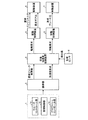
図1は、実施形態による前後加速度制御装置3を備えた車両制御システムの全体構成を示した例示的なブロック図である。この車両制御システムは、ドライバの運転操作によらない自動制御で走行するクルーズコントロールモードと、ドライバの運転操作に従って走行する通常走行モードとの、2種類の制御モードで走行可能な車両に搭載される。なお、クルーズコントロールモードは、「第1の走行モード」の一例であり、通常走行モードは、「第2の走行モード」の一例である。
FIG. 1 is an exemplary block diagram showing an overall configuration of a vehicle control system provided with a longitudinal
図1に示すように、車両制御システムは、加速度要求部1と、調停器2と、前後加速度制御装置3と、駆動制御装置4と、制動制御装置5と、駆動装置6と、制動装置7と、各種センサ8とを備える。
As shown in FIG. 1, the vehicle control system includes an
加速度要求部1は、クルーズコントロールモードで車両が走行する場合に、走行中の車両の状態に応じた加速度の要求値を出力する。具体的に、加速度要求部1は、クルーズコントロールモードを実現するアプリケーションとして、クルーズコントロール部1aと、車間制御部1bと、プリクラッシュコントロール部1cとを備える。クルーズコントロール部1aは、車両の走行速度(以下、車速と記載する)を所定の値に制御するための要求値を出力する。車間制御部1bは、先行車両との車間距離を所定範囲内に制御するための要求値を出力する。プリクラッシュコントロール部1cは、先行車両との衝突を回避するための要求値を出力する。
When the vehicle travels in the cruise control mode, the
調停器2は、加速度要求部1から入力される要求値が示す加速度を調停し、一制御周期内での要求値の変化量、つまり車両の前後方向の加速度の微分値であるジャークを、加速度要求部1の各アプリケーションからの加速度要求として出力する。また、調停器2は、走行中の車両の状態に応じて設定されるジャークの制限値を演算し、演算結果を、要求ジャーク制限値として出力する。
The
前後加速度制御装置3は、調停器2から入力される加速度要求および要求ジャーク制限値と、各種センサ8から入力される検出値とに基づいて、駆動要求および制動要求を算出する。ここで、各種センサ8は、エンジンの回転数(車速に比例する)を検出するセンサや、車両に発生している加速度を検出する加速度センサ、ドライバの運転操作量(ペダルストローク)を検出するストロークセンサなど、車両の制御に必要な情報を検出可能な複数のセンサにより構成される。これにより、前後加速度制御装置3には、検出値として、車速に関するデータや、車両に加わっている加速度に関するデータ、ドライバの運転操作量(ペダルストローク)に関するデータ、エンジンにおける燃料噴射量に関するデータなどが入力される。
The longitudinal
駆動制御装置4は、車両を駆動するための駆動装置6を制御する。たとえば、駆動制御装置4は、駆動装置6の一例としてのパワートレインを制御するパワートレインECU(Electronic Control Unit)により構成される。駆動制御装置4は、前後加速度制御装置3から入力される駆動要求に応じて、エンジンのトルク要求値(要求エンジントルク)と、自動変速装置のギア比の要求値(要求ギア比)とを算出し、算出結果を駆動装置6に出力する。
The drive control device 4 controls a
制動制御装置5は、車両を制動するための制動装置7を制御するブレーキECUにより構成される。制動制御装置5は、前後加速度制御装置3から入力される制動要求に応じて、ブレーキアクチュエータが発生させるホイールシリンダ圧の要求値(要求ブレーキ圧)を算出し、算出結果を制動装置7に出力する。
The
図2は、実施形態による前後加速度制御装置3の内部構成を示した例示的なブロック図である。図2に示すように、前後加速度制御装置3は、ジャーク制御部3aと、操作量算出部3bと、実加速度値算出部3cと、走行抵抗値算出部3dと、駆動出力値算出部3eと、補正値算出部3fと、減算器3gとを備える。なお、実加速度値算出部3c、走行抵抗値算出部3d、および駆動出力値算出部3eは、それぞれ、「加速度値取得部」、「走行抵抗値取得部」、および「駆動出力値取得部」の一例である。また、減算器3gは、「走行抵抗値補正部」の一例である。さらに、前後加速度制御装置3は、分配器3hと、駆動フィードフォワード(以下、FFと記載する)制御部3iと、駆動フィードバック(以下、FBと記載する)制御部3jと、制動FF制御部3kと、制動FB制御部3lと、加算器3mと、加算器3nとを備える。
FIG. 2 is an exemplary block diagram showing an internal configuration of the longitudinal
ジャーク制御部3aは、調停器2から入力される要求ジャーク制限値に基づき加速度の変化量を制限しながら、調停器2から入力される加速度要求に対応する加速度を算出し、算出結果を、操作量算出部3bに対する要求値として出力する。
The
操作量算出部3bは、ジャーク制御部3aから入力される要求値と、減算器3gから入力される走行抵抗値(補正後の走行抵抗値、詳細は後述する)とに基づいて、駆動制御装置4および制動制御装置5に対する制御指令に対応する操作量を算出する。具体的に、操作量算出部3bは、加算器3oと、目標加速度算出部3pとを備える。加算器3oは、ジャーク制御部3aから入力される要求値と、減算器3gから入力される走行抵抗値とを加算する。目標加速度算出部3pは、加算器3oによる加算結果に基づいて、車両に発生させるべき目標加速度を算出し、算出結果を操作量として出力する。
The operation
実加速度値算出部3cは、走行中の車両の前後方向の加速度を示す加速度値を取得する。具体的に、実加速度値算出部3cは、実車速の検出値に基づいて、車両に実際に発生している加速度の値(以下、実加速度値と記載する)を算出する。なお、実加速度は、実車速の時間微分に対応する。 The actual acceleration value calculation unit 3c acquires an acceleration value that indicates the acceleration in the front-rear direction of the traveling vehicle. Specifically, the actual acceleration value calculation unit 3c calculates the value of the acceleration actually generated in the vehicle (hereinafter referred to as the actual acceleration value) based on the detected value of the actual vehicle speed. The actual acceleration corresponds to the time derivative of the actual vehicle speed.
走行抵抗値算出部3dは、走行中の車両に加わる走行抵抗を示す走行抵抗値を取得する。具体的に、走行抵抗値算出部3dは、実車速の検出値と、加速度センサの検出値(加速度センサ値)と、実加速度値とに基づいて、走行抵抗値を算出(推定)する。ここで、走行抵抗とは、車両の走行を妨げる方向に働く力(加速度)の合計に対応し、たとえば、路面の勾配に応じて車両に加わる加速度(勾配抵抗)や、タイヤに発生する転がり抵抗、車体に加わる空気抵抗などを含む。なお、実施形態では、実車速の検出値、加速度センサ値、および実加速度値の3種類の検出値のみならず、これら以外の他の検出値をも考慮して走行抵抗値を算出してもよい。ここで、走行抵抗値は、“力”であるため、加速度の要求値や実加速度などの“加速度”との比較や加減演算を行うためには、“加速度”に対応した値に変換する必要がある。そのため、走行抵抗算出部3dは、算出した走行抵抗値に基づいて、走行抵抗値を加速度に変換した値である走行抵抗相当加速度値を算出する。走行抵抗相当加速度値は、たとえば、走行抵抗値を所定の車両質量で除算したり、あるいは、走行抵抗値を、タイヤなどの走行に伴って回転する部分の慣性モーメントを所定の車両質量に加えた値で除算したりすることで、算出できる。 The traveling resistance value calculation unit 3d acquires a traveling resistance value indicating a traveling resistance applied to a vehicle in motion. Specifically, the traveling resistance value calculation unit 3d calculates (estimates) the traveling resistance value based on the detected value of the actual vehicle speed, the detected value of the acceleration sensor (acceleration sensor value), and the actual acceleration value. Here, the running resistance corresponds to the total force (acceleration) acting in the direction that hinders the running of the vehicle. For example, the acceleration (gradient resistance) applied to the vehicle according to the gradient of the road surface or the rolling resistance generated on the tire , Including air resistance applied to the vehicle body. In the embodiment, the running resistance value may be calculated taking into consideration not only the detected values of the actual vehicle speed, the acceleration sensor value, and the actual acceleration value, but also other detected values other than these. Good. Here, since the traveling resistance value is "force", it is necessary to convert it to a value corresponding to "acceleration" in order to perform comparison with the "acceleration" such as the required value of acceleration or actual acceleration etc. There is. Therefore, the running resistance calculation unit 3d calculates, based on the calculated running resistance value, a running resistance equivalent acceleration value which is a value obtained by converting the running resistance value into an acceleration. The running resistance equivalent acceleration value is obtained by, for example, dividing the running resistance value by a predetermined vehicle mass or adding the moment of inertia of a portion rotating with the running of a tire or the like to a predetermined vehicle mass. It can be calculated by dividing by a value.
駆動出力値算出部3eは、走行中の車両の駆動装置6の出力を示す駆動出力値を取得する。具体的に、駆動出力値算出部3eは、ペダルストロークの検出値と、燃料噴射量の検出値とに基づいて、駆動出力値を算出する。なお、実施形態では、ペダルストローク(および/または燃料噴射量)と駆動出力値との対応関係を記憶するマップなどを用いて、ペダルストローク(および/または燃料噴射量)の検出値に応じて駆動出力値を決定してもよい。ここで、上記の走行抵抗値と同様、駆動出力値は、“力”であるため、要求加速度や実加速度などの“加速度”との比較や加減演算を行うためには、“加速度”に対応した値に変換する必要がある。そのため、駆動出力算出部3eは、算出した駆動出力値に基づいて、駆動出力値を加速度に変換した値である駆動出力相当加速度値を算出する。駆動出力相当加速度値は、たとえば、駆動出力値を所定の車両質量で除算したり、あるいは、駆動出力値を、タイヤなどの走行に伴って回転する部分の慣性モーメントを所定の車両質量に加えた値で除算したりすることで、算出できる。
The drive output
ところで、一般に、加速度センサなどによる検出値の信頼度は、経年劣化や温度条件などに応じて変化する。したがって、検出値を用いた演算結果は、常に現実の値と一致するとは限らない。たとえば、実施形態による走行抵抗値算出部3dは、上記のように、加速度センサ値を含む3種類の検出値に基づいて走行抵抗値を算出しているため、検出値の信頼度が低下すると、走行抵抗値算出部3dが算出する走行抵抗値が誤差を含むことがある。しかしながら、走行抵抗値が誤差を含んでいると、たとえば通常走行モードからクルーズコントロールモードへの移行時において、操作量算出部3bによる操作量の算出に悪影響が及ぶ可能性がある。
By the way, in general, the reliability of the detection value by the acceleration sensor or the like changes according to the aged deterioration, the temperature condition and the like. Therefore, the calculation result using the detected value does not always coincide with the actual value. For example, since the traveling resistance value calculation unit 3d according to the embodiment calculates the traveling resistance value based on the three types of detected values including the acceleration sensor value as described above, when the reliability of the detected values decreases, The running resistance value calculated by the running resistance value calculation unit 3d may include an error. However, if the traveling resistance value includes an error, for example, at the time of transition from the normal traveling mode to the cruise control mode, the calculation of the operation amount by the operation
図3は、実施形態において走行抵抗値が誤差を含むことの影響を説明するための例示図である。図3の縦軸の次元は、加速度の次元である。 FIG. 3 is an exemplary view for explaining the influence of the running resistance value including an error in the embodiment. The dimension of the vertical axis in FIG. 3 is the dimension of acceleration.
図3の左側のダイアグラムは、通常走行モードにおいて、駆動出力相当加速度値がX1であるにも関わらず、実加速度値がX1より小さいX2となっている例を示している。この例では、車両に走行抵抗が加わっていることによって、実加速度値が駆動出力相当加速度値よりも小さくなっているものと考えられる。したがって、図3の左側のダイアグラムでは、X1とX2との差分であるY1が、実際に発生している走行抵抗に対応する加速度値と考えられる。 The diagram on the left side of FIG. 3 shows an example in which the actual acceleration value is X2 smaller than X1 although the drive output equivalent acceleration value is X1 in the normal running mode. In this example, it is considered that the actual acceleration value is smaller than the drive output equivalent acceleration value due to the travel resistance being added to the vehicle. Therefore, in the diagram on the left side of FIG. 3, Y1 which is the difference between X1 and X2 is considered to be an acceleration value corresponding to the actually generated traveling resistance.
ここで、車両の制御モードが通常走行モードからクルーズコントロールモードに切り替わる場合を考える。この場合、車両に発生する加速度が制御モードの切り替えの前後で急激に変化するのを抑制するため、車両に加わる走行抵抗を考慮に入れながら、実加速度値を維持する必要がある。したがって、クルーズコントロールモードにおいて車両に要求される加速度は、基本的には、実加速度値算出部3cにより算出される実加速度値と、走行抵抗値算出部3dにより算出される走行抵抗相当加速度値との合計値となる。 Here, it is assumed that the control mode of the vehicle is switched from the normal travel mode to the cruise control mode. In this case, it is necessary to maintain the actual acceleration value while taking into consideration the running resistance applied to the vehicle, in order to suppress the rapid change of the acceleration generated in the vehicle before and after the switching of the control mode. Therefore, basically, the acceleration required of the vehicle in the cruise control mode is the actual acceleration value calculated by the actual acceleration value calculation unit 3c and the traveling resistance equivalent acceleration value calculated by the traveling resistance value calculation unit 3d. It becomes the total value of
上述したように、走行抵抗値算出部3dにより算出される走行抵抗値は、加速度センサ値などの検出値に基づく値であるため、誤差を含むことがある。したがって、クルーズコントロールモードでは、通常走行モードにおいて実際に発生している走行抵抗値(具体的には、実加速度値と駆動出力値との差分に相当する抵抗値)とは異なる走行抵抗値が算出されることがある。 As described above, the traveling resistance value calculated by the traveling resistance value calculation unit 3d is a value based on a detected value such as an acceleration sensor value, and thus may include an error. Therefore, in the cruise control mode, a running resistance value different from the running resistance value actually generated in the normal running mode (specifically, the resistance value corresponding to the difference between the actual acceleration value and the drive output value) is calculated. There is something to be done.
図3の右側のダイアグラムは、クルーズコントロールモードにおいて算出される走行抵抗値を加速度の値に変換した走行抵抗相当加速度値Y2が、通常走行モードにおいて発生している走行抵抗値による加速度値Y1よりも大きい例を示している。この例では、走行抵抗相当加速度値Y2と実加速度X2とを加算した目標加速度X3が、実加速度X2と実際に発生している走行抵抗に対応する加速度値Y1とを加えた加速度X1よりも大きくなっている。したがって、車両に発生する加速度が制御モードの切り替えの前後で急激に変化するのを抑制するためには、走行抵抗値算出部3dにより算出される走行抵抗値を、Y2とY1との差分Y3(走行抵抗値の誤差による加速度)に基づいて補正することが望まれる。 In the diagram on the right side of FIG. 3, the traveling resistance equivalent acceleration value Y2 obtained by converting the traveling resistance value calculated in the cruise control mode into the acceleration value is higher than the acceleration value Y1 due to the traveling resistance value generated in the normal traveling mode. It shows a big example. In this example, the target acceleration X3 obtained by adding the running resistance equivalent acceleration value Y2 and the actual acceleration X2 is larger than the acceleration X1 obtained by adding the actual acceleration X2 and the acceleration value Y1 corresponding to the running resistance actually generated. It has become. Therefore, in order to suppress that the acceleration generated in the vehicle changes rapidly before and after the switching of the control mode, the running resistance value calculated by the running resistance value calculation unit 3d is the difference Y3 between Y2 and Y1 ( It is desirable to correct based on the acceleration) due to the error of the running resistance value.
ここで、検出値に基づいて算出される走行抵抗相当加速度値Y2は、通常走行モードにおいても算出可能である。したがって、実施形態では、通常走行モードにおいて実際に発生している走行抵抗に対応する加速度値Y1および走行抵抗相当加速度Y2をそれぞれ異なる手法で算出するとともに、当該実際に発生している走行抵抗に対応する加速度値Y1および走行抵抗相当加速度Y2の差分Y3を補正値として予め算出しておくことで、クルーズコントロールモードに移行した後に検出値に基づいて算出される走行抵抗値を補正することが望まれる。 Here, the traveling resistance equivalent acceleration value Y2 calculated based on the detected value can be calculated also in the normal traveling mode. Therefore, in the embodiment, the acceleration value Y1 and the traveling resistance equivalent acceleration Y2 corresponding to the traveling resistance actually generated in the normal traveling mode are calculated by different methods, and the corresponding traveling resistance actually generated is handled. It is desirable to correct the traveling resistance value calculated based on the detected value after shifting to the cruise control mode by calculating in advance the difference Y3 between the acceleration value Y1 and the traveling resistance equivalent acceleration Y2 as the correction value. .
そこで、図2に戻り、実施形態では、走行抵抗値の誤差を補正するため、以下のような構成が設けられている。 Therefore, referring back to FIG. 2, in the embodiment, the following configuration is provided in order to correct the error of the traveling resistance value.
補正値算出部3fは、実加速度値算出部3c、走行抵抗値算出部3d、および駆動出力値算出部3eからそれぞれ得られる実加速度値、走行抵抗相当加速度値、および駆動出力相当加速度値に基づいて、走行抵抗値算出部3dにより算出された走行抵抗値の誤差に対応する補正値を算出する。具体的に、補正値算出部3fは、駆動出力相当加速度値および実加速度値の差分と、走行抵抗相当加速度値との差分に基づいて、補正値を算出する。補正値の算出は、通常走行モードにおいて行われる。
The correction
なお、一般に、クルーズコントロールモードは、通常走行モードから移行する形で実行される。したがって、実施形態では、補正値は、車両の制御モードが通常走行モードからクルーズコントロールモードに切り替わった際、既に算出済みとなっている。補正値算出部3fは、少なくとも通常走行モードからクルーズコントロールモードに切り替わった当初に、予め算出しておいた補正値を減算器3gに出力する。そして、減算器3gは、走行抵抗値算出部3dから入力される走行抵抗相当加速度値から、補正値算出部3fから入力される補正値を減算し、減算結果を操作量算出部3bに出力する。このように、実施形態では、少なくとも通常走行モードからクルーズコントロールモードに切り替わった当初に、減算器3gによって、走行抵抗値算出部3dにより算出された走行抵抗相当加速度値が補正される。
Generally, the cruise control mode is executed in the form of transition from the normal driving mode. Therefore, in the embodiment, the correction value is already calculated when the control mode of the vehicle is switched from the normal travel mode to the cruise control mode. The correction
ここで、補正値をより正確に算出するためには、車両の走行状態がある程度安定した状態(以下、安定状態と記載する)であることが望ましい。つまり、実施形態では、補正値の算出が、たとえば所定時間内における加速度値や駆動出力値の変化がある一定の範囲内にある状態で実行されることが望ましい。 Here, in order to calculate the correction value more accurately, it is desirable that the traveling state of the vehicle be stable to a certain extent (hereinafter referred to as the stable state). That is, in the embodiment, it is desirable that the calculation of the correction value is performed, for example, in a state where changes in the acceleration value and the drive output value within a predetermined time are within a certain range.
そこで、実施形態では、補正値算出部3fは、車両の制御モードが通常走行モードであり、かつ、車両の走行状態が安定状態であるという条件が満たされた状態である場合に、実加速度値、走行抵抗値、および駆動出力値を取得し、取得した実加速度値、走行抵抗値、および駆動出力値に基づいて、補正値を算出する。
Therefore, in the embodiment, when the control
図4は、実施形態による前後加速度制御装置において補正値が算出される条件を説明するための例示図である。図4の例では、区間A1およびA3において、駆動出力値および実加速度値が一定値となっている一方、区間A2において、駆動出力値および実加速度値が変動している。すなわち、図4の例では、区間A1およびA3が、安定状態に該当し、区間A2が、安定状態とは異なるいわゆる過渡状態に該当する。したがって、図4の例では、区間A1およびA3において、補正値の算出が行われる一方、区間A2においては、補正値の算出が行われない。 FIG. 4 is an exemplary view for explaining a condition under which the correction value is calculated in the longitudinal acceleration control device according to the embodiment. In the example of FIG. 4, while the drive output value and the actual acceleration value are constant values in the sections A1 and A3, the drive output value and the actual acceleration value fluctuate in the section A2. That is, in the example of FIG. 4, the sections A1 and A3 correspond to the stable state, and the section A2 corresponds to the so-called transient state different from the stable state. Therefore, in the example of FIG. 4, while calculation of the correction value is performed in the sections A1 and A3, calculation of the correction value is not performed in the section A2.
なお、安定状態は、所定時間内における実加速度値および駆動出力値の変化がある一定の範囲内にある状態に限らない。たとえば、所定時間内におけるペダルストロークや燃料噴射量の変化がある一定の範囲内にある状態も、安定状態に該当するとして判断してもよい。さらに、自動変速装置のギア比が切り替え中の状態でないか否かを、安定状態に該当すると判断するための判断基準の一つとして考慮してもよい。 Note that the stable state is not limited to a state in which changes in the actual acceleration value and the drive output value within a predetermined time are within a certain range. For example, a state in which a change in the pedal stroke or the fuel injection amount within a predetermined time is within a certain range may also be determined as falling under the stable state. Furthermore, whether or not the gear ratio of the automatic transmission is not in the process of switching may be taken into consideration as one of the determination criteria for determining that it is in the stable state.
図5は、実施形態による前後加速度制御装置において補正値が算出される条件を図4とは異なる観点で説明するための例示図である。図5の例では、区間A12およびA14において、ペダルストロークが一定値となっている一方、区間A13およびA15において、ペダルストロークが変動している。したがって、図5の例では、区間A12およびA14が、安定状態に該当し、区間A13およびA15が、過渡状態に該当する。なお、図5の例では、区間A11も、ペダルストロークが一定値となっている区間を含んでいる。しかしながら、区間A11においては、自動変速装置のギア比が切り替え中となっているので、区間A11は、安定状態には該当しない。 FIG. 5 is an exemplary view for explaining a condition under which the correction value is calculated in the longitudinal acceleration control device according to the embodiment from a viewpoint different from FIG. 4. In the example of FIG. 5, while the pedal stroke has a constant value in sections A12 and A14, the pedal stroke varies in sections A13 and A15. Therefore, in the example of FIG. 5, sections A12 and A14 correspond to the stable state, and sections A13 and A15 correspond to the transient state. In the example of FIG. 5, the section A11 also includes a section in which the pedal stroke has a constant value. However, in the section A11, the gear ratio of the automatic transmission is being switched, so the section A11 does not correspond to the stable state.
ここで、実施形態では、補正値算出部3fは、車両の走行状態が安定状態であるという所定の条件が満たされた状態が継続する場合、補正値を更新する。つまり、補正値算出部3fは、車両の制御モードが通常走行モードであり、かつ、車両の走行状態が安定状態である間、補正値を繰り返し算出し、最新の補正値により、過去の補正値を更新する。
Here, in the embodiment, the correction
図2に戻り、分配器3hは、操作量算出部3bから入力される操作量を、駆動FF制御部3i、駆動FB制御部3j、制動FF制御部3k、および制動FB制御部3lに分配して出力する。
Returning to FIG. 2, the distributor 3h distributes the operation amount input from the operation
駆動FF制御部3iは、分配器3hからの入力に応じたFF指令値を出力する。また、駆動FB制御部3jは、分配器3hからの入力と、実加速度値算出部3cからの入力とに応じたFB指令値を出力する。そして、加算器3mは、駆動FF制御部3iおよび駆動FB制御部3jからの入力を加算し、加算結果を、駆動制御装置4に対する駆動要求として出力する。
The drive
制動FF制御部3kは、分配器3hからの入力に応じたFF指令値を出力する。また、制動FB制御部3lは、分配器3hからの入力と、実加速度値算出部3cからの入力とに応じたFB指令値を出力する。そして、加算器3nは、制動FF制御部3kおよび制動FB制御部3lからの入力を加算し、加算結果を、制動制御装置5に対する制動要求として出力する。
The braking
次に、実施形態による前後加速度制御装置3の制御動作について説明する。
Next, the control operation of the longitudinal
図6は、実施形態による前後加速度制御装置3が通常走行モードにおいて実行する処理を示した例示的なフローチャートである。この図6の処理フローは、たとえば、通常走行モードにおいて繰り返し実行される。
FIG. 6 is an exemplary flowchart showing processing executed by the longitudinal
図6の処理フローでは、まず、S1において、実加速度値算出部3c、走行抵抗値算出部3d、および駆動出力値算出部3eは、各種センサ8からの検出値の入力を受け付ける。実加速度値算出部3cには、実車速の検出値が入力され、走行抵抗値算出部3dは、実車速の検出値および加速度センサ値が入力され、駆動出力値算出部3eは、ペダルストロークおよび燃料噴射量の検出値が入力される。なお、走行抵抗値算出部3dには、実車速を示すセンサ値に基づいて実加速度値算出部3cによって算出される実加速度値も入力される。
In the process flow of FIG. 6, first, in S1, the actual acceleration value calculation unit 3c, the traveling resistance value calculation unit 3d, and the drive output
S2において、走行抵抗値算出部3dは、実車速の検出値と、実加速度値と、加速度センサ値とに基づいて、走行抵抗値を算出する。具体的に、走行抵抗値算出部3dは、上記の各種入力値に基づいて推定される勾配抵抗や転がり抵抗や空気抵抗などを合算し、走行抵抗値(および走行抵抗相当加速度値)を算出する。 In S2, the traveling resistance value calculation unit 3d calculates the traveling resistance value based on the detected value of the actual vehicle speed, the actual acceleration value, and the acceleration sensor value. Specifically, the running resistance value calculation unit 3d calculates the running resistance value (and the running resistance equivalent acceleration value) by summing up the gradient resistance, the rolling resistance, the air resistance, etc. estimated based on the various input values described above. .
S3において、駆動出力値算出部3eは、ペダルストロークの検出値と、燃料噴射量の検出値とに基づいて、駆動出力値(および駆動出力相当加速度値)を算出する。
In S3, the drive output
S4において、補正値算出部3fは、駆動出力相当加速度値と、走行抵抗値相当加速度と、実加速度値とに基づいて、補正値を算出する。具体的に、補正値算出部3fは、駆動出力相当加速度値および実加速度値の差分(走行抵抗相当加速度値の真値と考えられる値)と、走行抵抗相当加速度値(検出値に基づいて算出される値)との差分をとって、補正値を算出する。
In S4, the correction
S5において、補正値算出部3fは、安定状態が継続中か否かを判断する。具体的に、補正値算出部3fは、所定時間内における実加速度値および駆動出力値の変化がある一定の範囲内にあるか否かや、所定時間内におけるペダルストローク(または燃料噴射量)の変化がある一定の範囲内にあるか否か、などを判断する。なお、このとき、自動変速装置のギア比が切り替え中の状態でないか否かも、判断基準の一つとして考慮されてよい。
In S5, the correction
S5において、安定状態が継続中であると判断された場合、S6に処理が進む。そして、S6において、補正値算出部3fは、自身が記憶する補正値を、直近のS4で算出された最新の補正値に更新する。そして、処理が終了する。
If it is determined in S5 that the stable state is continuing, the process proceeds to S6. Then, in S6, the correction
一方、S5において、安定状態が継続中でないと判断された場合、S6のような処理は実行されず、そのまま処理が終了する。つまり、S5において、安定状態が継続中でないと判断された場合、補正値算出部3fは、自身が記憶する補正値を、最新の補正値としてそのまま記憶し、処理が終了する。
On the other hand, if it is determined in S5 that the stable state is not continuing, the process as in S6 is not performed, and the process ends. That is, when it is determined in S5 that the stable state is not continuing, the correction
図7は、実施形態による前後加速度制御装置3がクルーズコントロールモードにおいて実行する処理を示した例示的なフローチャートである。この図7の処理フローは、たとえば、車両の制御モードが通常走行モードからクルーズコントロールモードに切り替わった当初に実行される。
FIG. 7 is an exemplary flowchart showing processing executed by the longitudinal
図7の処理フローでは、まず、S11において、実加速度値算出部3cおよび走行抵抗値算出部3dは、各種センサ8からの検出値の入力を受け付ける。実加速度値算出部3cには、実車速の検出値が入力され、走行抵抗値算出部3dは、実車速の検出値および加速度センサ値が入力される。なお、走行抵抗値算出部3dには、実車速を示すセンサ値に基づいて実加速度値算出部3cによって算出される実加速度値も入力される。 In the process flow of FIG. 7, first, in S11, the actual acceleration value calculation unit 3c and the traveling resistance value calculation unit 3d receive input of detection values from the various sensors 8. The detected value of the actual vehicle speed is input to the actual acceleration value calculating unit 3c, and the detected value of the actual vehicle speed and the acceleration sensor value are input to the traveling resistance value calculating unit 3d. The actual acceleration value calculated by the actual acceleration value calculating unit 3c is also input to the running resistance value calculating unit 3d based on the sensor value indicating the actual vehicle speed.
S12において、走行抵抗値算出部3dは、上記の各種入力値に基づいて推定される勾配抵抗や転がり抵抗や空気抵抗などを合算し、走行抵抗値(および走行抵抗相当加速度値)を算出する。 In S12, the traveling resistance value calculation unit 3d calculates the traveling resistance value (and the traveling resistance equivalent acceleration value) by adding up the gradient resistance, the rolling resistance, the air resistance and the like estimated based on the various input values described above.
S13において、減算器3gは、補正値算出部3fから入力される補正値に基づき、走行抵抗値算出部3dから入力される走行抵抗値を補正する。具体的に、減算器3gは、走行抵抗値から補正値を減算し、減算結果を操作量算出部3bに出力する。
In S13, the
S14において、操作量算出部3bは、ジャーク制御部3aから入力される要求値と、減算器3gから入力される(補正後の)走行抵抗値とに基づき、車両に発生させるべき目標加速度を算出する。具体的に、操作量算出部3bの加算器3oは、要求値と走行抵抗相当加速度値とを加算し、加算結果を出力する。そして、操作量算出部3bの目標加速度算出部3pは、加算器3oからの入力に基づき、操作量を算出する。
In S14, the manipulated
S15において、分配器3hは、操作量算出部3bから入力される目標加速度を、駆動FF制御部3i、駆動FB制御部3j、制動FF制御部3k、および制動FB制御部3lに分配して出力する。
In S15, the distributor 3h distributes and outputs the target acceleration input from the operation
S16において、前後加速度制御装置3は、駆動制御装置4に対する駆動要求、および制動制御装置5に対する制動要求を出力する。具体的に、加算器3mは、駆動FF制御部3iからのFF指令値および駆動FB制御部3jからFB指令値に基づく駆動要求を出力し、加算器3nは、制動FF制御部3kからのFF指令値および制動FB制御部3lからのFB指令値に基づく制動要求を出力する。そして、処理が終了する。
In S16, the longitudinal
以上説明したように、実施形態による前後加速度制御装置3は、通常走行モードにおいて所定の条件が満たされた状態で得られた駆動出力相当加速度値、走行抵抗相当加速度値、および実加速度値から、走行抵抗の誤差に対応する補正値を算出する補正値算出部3fと、少なくとも通常走行モードがクルーズコントロールモードに切り替わった当初に、走行抵抗相当加速度値を補正値で補正する減算器3gと、を備える。これにより、通常走行モードからクルーズコントロールモードへの移行時に、誤差を含む走行抵抗値に基づいた自動制御が行われるのを抑制することができる。
As described above, in the longitudinal
また、実施形態による補正値算出部3fは、駆動出力相当加速度値および実加速度値の差分と、走行抵抗相当加速度値との差分に基づいて、補正値を算出する。これにより、駆動出力値および実加速度値の差分によって得られる走行抵抗値の真値と考えられる値に基づいて走行抵抗値の誤差を算出し、補正値を算出することができる。
Further, the correction
また、実施形態において、補正値を算出するための所定の条件は、所定時間内における実加速度値の変化がある一定の範囲内(第1の範囲内)にあることを含む。これにより、車両の走行状態がある程度安定した状態で補正値を算出することができる。 In the embodiment, the predetermined condition for calculating the correction value includes that the change of the actual acceleration value within the predetermined time is within a certain range (within the first range). Thereby, the correction value can be calculated in a state where the traveling state of the vehicle is stable to some extent.
同様に、実施形態において、補正値を算出するための所定の条件は、所定時間内における駆動出力値の変化がある一定の範囲内(第2の範囲内)にあることを含む。これにより、車両の走行状態がある程度安定した状態で補正値を算出することができる。 Similarly, in the embodiment, the predetermined condition for calculating the correction value includes that the change of the drive output value within a predetermined time is within a certain range (within the second range). Thereby, the correction value can be calculated in a state where the traveling state of the vehicle is stable to some extent.
また、実施形態による補正値算出部3fは、上記の所定の条件が満たされた状態が継続する場合、補正値を更新する。これにより、最新の補正値により、走行抵抗値を補正することができる。
In addition, the correction
以上、本発明の実施形態および変形例を説明したが、上述した実施形態および変形例はあくまで一例であって、発明の範囲を限定することは意図していない。上述した実施形態および変形例は、様々な形態で実施されることが可能であり、発明の要旨を逸脱しない範囲で、種々の省略、置き換え、変更を行うことができる。また、上述した実施形態および変形例は、発明の範囲や要旨に含まれるとともに、特許請求の範囲に記載された発明とその均等の範囲に含まれる。 As mentioned above, although embodiment and the modification of this invention were described, the embodiment and the modification which were mentioned above are an example to the last, and it is not intending limiting the range of invention. The embodiments and modifications described above can be implemented in various forms, and various omissions, substitutions, and modifications can be made without departing from the scope of the invention. Moreover, while being included in the range and summary of invention, the embodiment and modification which were mentioned above are included in the invention described in the claim, and its equivalent range.
3…前後加速度制御装置(車両の制御装置)、3b…操作量算出部、3c…実加速度値算出部(加速度値取得部)、3d…走行抵抗値算出部(走行抵抗値取得部)、3e…駆動出力値算出部(駆動出力値取得部)、3f…補正値算出部、3g…減算器(走行抵抗値補正部)、6…駆動装置、7…制動装置。 3 ... longitudinal acceleration control device (vehicle control device), 3b ... operation amount calculation unit, 3c ... actual acceleration value calculation unit (acceleration value acquisition unit), 3d ... traveling resistance value calculation unit (travel resistance value acquisition unit), 3e ... Drive output value calculation unit (drive output value acquisition unit), 3f ... Correction value calculation unit, 3g ... Subtractor (travel resistance value correction unit), 6 ... Drive device, 7 ... Braking device.
Claims (4)
前記走行中の車両に加わる走行抵抗を示す走行抵抗値に基づいて走行抵抗相当加速度値を取得する走行抵抗値取得部と、
前記走行中の車両の前後方向の加速度を示す加速度値を取得する加速度値取得部と、
ドライバの運転操作によらずに前記車両の前後方向の加速または減速を制御する自動制御による第1の走行モードにおいて、前記車両の前後方向の加速度合いを示す要求値と前記走行抵抗値とに基づいて、前記駆動装置および制動装置の少なくとも一方を制御する操作量を算出する操作量算出部と、
前記ドライバの運転操作に基づく第2の走行モードにおいて前記車両の走行状態が安定状態となっている場合における、前記駆動出力相当加速度値および前記加速度値の差分と、前記走行抵抗相当加速度値との差分に基づいて、前記走行抵抗の誤差に対応する補正値を算出する補正値算出部と、
少なくとも前記第2の走行モードが前記第1の走行モードに切り替わった当初に、前記走行抵抗値を前記補正値で補正する走行抵抗値補正部と、を備える、車両の制御装置。 Drive output value acquisition unit for acquiring a drive output equivalent acceleration value based on a drive output value indicating an output of a drive device of a traveling vehicle , which is calculated based on at least one of a pedal stroke and a fuel injection amount in an engine When,
A traveling resistance value acquiring unit that acquires a traveling resistance equivalent acceleration value based on a traveling resistance value indicating a traveling resistance applied to the vehicle while traveling;
An acceleration value acquisition unit that acquires an acceleration value that indicates an acceleration in the front-rear direction of the traveling vehicle;
In a first travel mode by automatic control that controls acceleration or deceleration in the front-rear direction of the vehicle regardless of the driving operation of the driver, based on the required value indicating the acceleration in the front-rear direction of the vehicle and the travel resistance value An operation amount calculation unit that calculates an operation amount for controlling at least one of the drive device and the braking device;
Between the driving output equivalent acceleration value and the difference between the acceleration value and the running resistance equivalent acceleration value when the traveling state of the vehicle is in a stable state in the second traveling mode based on the driving operation of the driver A correction value calculation unit that calculates a correction value corresponding to the error of the running resistance based on the difference ;
A control device for a vehicle, comprising: a traveling resistance value correction unit that corrects the traveling resistance value with the correction value at least when the second traveling mode is switched to the first traveling mode.
Priority Applications (5)
| Application Number | Priority Date | Filing Date | Title |
|---|---|---|---|
| JP2016055751A JP6528708B2 (en) | 2016-03-18 | 2016-03-18 | Vehicle control device |
| DE112017001405.0T DE112017001405T5 (en) | 2016-03-18 | 2017-03-15 | Control device for a vehicle |
| CN201780017642.4A CN109070899A (en) | 2016-03-18 | 2017-03-15 | The control device of vehicle |
| PCT/JP2017/010344 WO2017159716A1 (en) | 2016-03-18 | 2017-03-15 | Control device for vehicle |
| US16/084,003 US20200290609A1 (en) | 2016-03-18 | 2017-03-15 | Control device for vehicle |
Applications Claiming Priority (1)
| Application Number | Priority Date | Filing Date | Title |
|---|---|---|---|
| JP2016055751A JP6528708B2 (en) | 2016-03-18 | 2016-03-18 | Vehicle control device |
Publications (2)
| Publication Number | Publication Date |
|---|---|
| JP2017170928A JP2017170928A (en) | 2017-09-28 |
| JP6528708B2 true JP6528708B2 (en) | 2019-06-12 |
Family
ID=59850273
Family Applications (1)
| Application Number | Title | Priority Date | Filing Date |
|---|---|---|---|
| JP2016055751A Expired - Fee Related JP6528708B2 (en) | 2016-03-18 | 2016-03-18 | Vehicle control device |
Country Status (5)
| Country | Link |
|---|---|
| US (1) | US20200290609A1 (en) |
| JP (1) | JP6528708B2 (en) |
| CN (1) | CN109070899A (en) |
| DE (1) | DE112017001405T5 (en) |
| WO (1) | WO2017159716A1 (en) |
Families Citing this family (1)
| Publication number | Priority date | Publication date | Assignee | Title |
|---|---|---|---|---|
| JP6628818B2 (en) * | 2018-01-15 | 2020-01-15 | 本田技研工業株式会社 | Vehicle travel control device |
Family Cites Families (8)
| Publication number | Priority date | Publication date | Assignee | Title |
|---|---|---|---|---|
| JPH04362425A (en) * | 1991-06-06 | 1992-12-15 | Nissan Motor Co Ltd | Constant-speed running device for vehicle |
| JP3092444B2 (en) * | 1994-05-06 | 2000-09-25 | 日産自動車株式会社 | Constant-speed cruise control device for vehicles |
| JP2006297993A (en) * | 2005-04-15 | 2006-11-02 | Toyota Motor Corp | Driving force controller |
| JP5663969B2 (en) * | 2009-06-30 | 2015-02-04 | 株式会社アドヴィックス | Longitudinal acceleration control device |
| JP5927054B2 (en) * | 2012-06-11 | 2016-05-25 | 日立オートモティブシステムズ株式会社 | Vehicle travel control device |
| DE102012014809A1 (en) * | 2012-07-26 | 2014-01-30 | Volkswagen Ag | Method and device for detecting a curb crossing |
| US9403535B2 (en) * | 2012-09-19 | 2016-08-02 | Nissan Motor Co., Ltd. | Vehicle control device and vehicle control method |
| US20160016581A1 (en) * | 2013-03-04 | 2016-01-21 | Toyota Jidosha Kabushiki Kaisha | Travel motion control device for vehicle |
-
2016
- 2016-03-18 JP JP2016055751A patent/JP6528708B2/en not_active Expired - Fee Related
-
2017
- 2017-03-15 WO PCT/JP2017/010344 patent/WO2017159716A1/en active Application Filing
- 2017-03-15 DE DE112017001405.0T patent/DE112017001405T5/en not_active Withdrawn
- 2017-03-15 CN CN201780017642.4A patent/CN109070899A/en active Pending
- 2017-03-15 US US16/084,003 patent/US20200290609A1/en not_active Abandoned
Also Published As
| Publication number | Publication date |
|---|---|
| US20200290609A1 (en) | 2020-09-17 |
| WO2017159716A1 (en) | 2017-09-21 |
| JP2017170928A (en) | 2017-09-28 |
| CN109070899A (en) | 2018-12-21 |
| DE112017001405T5 (en) | 2018-11-29 |
Similar Documents
| Publication | Publication Date | Title |
|---|---|---|
| JP5471811B2 (en) | Braking control device | |
| JP5152003B2 (en) | Longitudinal acceleration control device | |
| US8340860B2 (en) | Acceleration detection device, acceleration detection method, and neutral control device employing same | |
| KR100618335B1 (en) | Vehicle speed control system | |
| EP3072768B1 (en) | Vehicle speed limit apparatus | |
| JP5625515B2 (en) | Vehicle braking / driving control device | |
| JP5663969B2 (en) | Longitudinal acceleration control device | |
| EP3072767B1 (en) | Vehicle speed limit apparatus | |
| JP2009025081A (en) | Road surface gradient estimation apparatus | |
| JPWO2018230341A1 (en) | Vehicle control device | |
| JP4424387B2 (en) | Travel control device | |
| JP6528708B2 (en) | Vehicle control device | |
| US7681962B2 (en) | Method for estimating master cylinder pressure during brake apply | |
| JP2014118065A (en) | Electronic control brake system and break control method | |
| EP3321142B1 (en) | Control device for straddled vehicle, and straddled vehicle | |
| US10086669B2 (en) | Stabilizer control device | |
| JP6245076B2 (en) | Output correction device for vehicle acceleration sensor | |
| JP6969264B2 (en) | Vehicle electronics | |
| JP5521943B2 (en) | Vehicle total weight estimation device | |
| WO2020039751A1 (en) | Display control device, display control program, and computer-readable non-transitory storage medium | |
| JP6641715B2 (en) | Road gradient estimation device and road gradient estimation method | |
| JP2008162564A (en) | Traveling controller for vehicle and traveling control method for vehicle | |
| JP2016094112A (en) | Vehicular travel controller | |
| JP6136870B2 (en) | Vehicle control device | |
| EP3321141B1 (en) | Control device for straddled vehicle, and straddled vehicle |
Legal Events
| Date | Code | Title | Description |
|---|---|---|---|
| A621 | Written request for application examination |
Free format text: JAPANESE INTERMEDIATE CODE: A621 Effective date: 20180206 |
|
| A131 | Notification of reasons for refusal |
Free format text: JAPANESE INTERMEDIATE CODE: A131 Effective date: 20181127 |
|
| A521 | Request for written amendment filed |
Free format text: JAPANESE INTERMEDIATE CODE: A523 Effective date: 20190124 |
|
| TRDD | Decision of grant or rejection written | ||
| A01 | Written decision to grant a patent or to grant a registration (utility model) |
Free format text: JAPANESE INTERMEDIATE CODE: A01 Effective date: 20190416 |
|
| A61 | First payment of annual fees (during grant procedure) |
Free format text: JAPANESE INTERMEDIATE CODE: A61 Effective date: 20190429 |
|
| R150 | Certificate of patent or registration of utility model |
Ref document number: 6528708 Country of ref document: JP Free format text: JAPANESE INTERMEDIATE CODE: R150 |
|
| LAPS | Cancellation because of no payment of annual fees |