JP6527178B2 - Vision sensor calibration device, method and program - Google Patents
Vision sensor calibration device, method and program Download PDFInfo
- Publication number
- JP6527178B2 JP6527178B2 JP2017003664A JP2017003664A JP6527178B2 JP 6527178 B2 JP6527178 B2 JP 6527178B2 JP 2017003664 A JP2017003664 A JP 2017003664A JP 2017003664 A JP2017003664 A JP 2017003664A JP 6527178 B2 JP6527178 B2 JP 6527178B2
- Authority
- JP
- Japan
- Prior art keywords
- camera
- parameter
- target mark
- image data
- robot
- Prior art date
- Legal status (The legal status is an assumption and is not a legal conclusion. Google has not performed a legal analysis and makes no representation as to the accuracy of the status listed.)
- Active
Links
Images


Classifications
-
- B—PERFORMING OPERATIONS; TRANSPORTING
- B25—HAND TOOLS; PORTABLE POWER-DRIVEN TOOLS; MANIPULATORS
- B25J—MANIPULATORS; CHAMBERS PROVIDED WITH MANIPULATION DEVICES
- B25J19/00—Accessories fitted to manipulators, e.g. for monitoring, for viewing; Safety devices combined with or specially adapted for use in connection with manipulators
- B25J19/02—Sensing devices
- B25J19/021—Optical sensing devices
- B25J19/023—Optical sensing devices including video camera means
-
- B—PERFORMING OPERATIONS; TRANSPORTING
- B25—HAND TOOLS; PORTABLE POWER-DRIVEN TOOLS; MANIPULATORS
- B25J—MANIPULATORS; CHAMBERS PROVIDED WITH MANIPULATION DEVICES
- B25J19/00—Accessories fitted to manipulators, e.g. for monitoring, for viewing; Safety devices combined with or specially adapted for use in connection with manipulators
- B25J19/02—Sensing devices
- B25J19/04—Viewing devices
-
- B—PERFORMING OPERATIONS; TRANSPORTING
- B25—HAND TOOLS; PORTABLE POWER-DRIVEN TOOLS; MANIPULATORS
- B25J—MANIPULATORS; CHAMBERS PROVIDED WITH MANIPULATION DEVICES
- B25J9/00—Programme-controlled manipulators
- B25J9/16—Programme controls
- B25J9/1628—Programme controls characterised by the control loop
- B25J9/163—Programme controls characterised by the control loop learning, adaptive, model based, rule based expert control
-
- B—PERFORMING OPERATIONS; TRANSPORTING
- B25—HAND TOOLS; PORTABLE POWER-DRIVEN TOOLS; MANIPULATORS
- B25J—MANIPULATORS; CHAMBERS PROVIDED WITH MANIPULATION DEVICES
- B25J9/00—Programme-controlled manipulators
- B25J9/16—Programme controls
- B25J9/1628—Programme controls characterised by the control loop
- B25J9/1653—Programme controls characterised by the control loop parameters identification, estimation, stiffness, accuracy, error analysis
-
- B—PERFORMING OPERATIONS; TRANSPORTING
- B25—HAND TOOLS; PORTABLE POWER-DRIVEN TOOLS; MANIPULATORS
- B25J—MANIPULATORS; CHAMBERS PROVIDED WITH MANIPULATION DEVICES
- B25J9/00—Programme-controlled manipulators
- B25J9/16—Programme controls
- B25J9/1656—Programme controls characterised by programming, planning systems for manipulators
- B25J9/1671—Programme controls characterised by programming, planning systems for manipulators characterised by simulation, either to verify existing program or to create and verify new program, CAD/CAM oriented, graphic oriented programming systems
-
- B—PERFORMING OPERATIONS; TRANSPORTING
- B25—HAND TOOLS; PORTABLE POWER-DRIVEN TOOLS; MANIPULATORS
- B25J—MANIPULATORS; CHAMBERS PROVIDED WITH MANIPULATION DEVICES
- B25J9/00—Programme-controlled manipulators
- B25J9/16—Programme controls
- B25J9/1694—Programme controls characterised by use of sensors other than normal servo-feedback from position, speed or acceleration sensors, perception control, multi-sensor controlled systems, sensor fusion
- B25J9/1697—Vision controlled systems
-
- G—PHYSICS
- G06—COMPUTING; CALCULATING OR COUNTING
- G06T—IMAGE DATA PROCESSING OR GENERATION, IN GENERAL
- G06T7/00—Image analysis
- G06T7/80—Analysis of captured images to determine intrinsic or extrinsic camera parameters, i.e. camera calibration
- G06T7/85—Stereo camera calibration
-
- B—PERFORMING OPERATIONS; TRANSPORTING
- B25—HAND TOOLS; PORTABLE POWER-DRIVEN TOOLS; MANIPULATORS
- B25J—MANIPULATORS; CHAMBERS PROVIDED WITH MANIPULATION DEVICES
- B25J9/00—Programme-controlled manipulators
- B25J9/16—Programme controls
- B25J9/1679—Programme controls characterised by the tasks executed
- B25J9/1692—Calibration of manipulator
-
- G—PHYSICS
- G06—COMPUTING; CALCULATING OR COUNTING
- G06T—IMAGE DATA PROCESSING OR GENERATION, IN GENERAL
- G06T2207/00—Indexing scheme for image analysis or image enhancement
- G06T2207/10—Image acquisition modality
- G06T2207/10004—Still image; Photographic image
- G06T2207/10012—Stereo images
-
- G—PHYSICS
- G06—COMPUTING; CALCULATING OR COUNTING
- G06T—IMAGE DATA PROCESSING OR GENERATION, IN GENERAL
- G06T2207/00—Indexing scheme for image analysis or image enhancement
- G06T2207/30—Subject of image; Context of image processing
- G06T2207/30204—Marker
Landscapes
- Engineering & Computer Science (AREA)
- Robotics (AREA)
- Mechanical Engineering (AREA)
- Computer Vision & Pattern Recognition (AREA)
- Physics & Mathematics (AREA)
- General Physics & Mathematics (AREA)
- Theoretical Computer Science (AREA)
- Multimedia (AREA)
- Manipulator (AREA)
- Length Measuring Devices By Optical Means (AREA)
- Image Analysis (AREA)
Description
本発明は、視覚センサのキャリブレーションに関し、特に複数のカメラを備えるステレオカメラを使用したキャリブレーション時においてターゲットマークを検出するキャリブレーション装置、方法、及びプログラムに関する。 The present invention relates to calibration of a visual sensor, and more particularly to a calibration apparatus, method, and program for detecting a target mark at the time of calibration using a stereo camera having a plurality of cameras.
ロボットシステムではロボットに視覚機能を持たせ、その視覚機能によって対象物の位置を認識させて、ワークのハンドリングや加工などの作業が行われている。その視覚機能はロボットのハンド付近に取り付けられた視覚センサやロボットの周辺に設置された視覚センサが対象物を撮像することによって実現される。このようなロボットシステムにおいては、ロボットから見た対象物の位置を取得するには、画像上の対象物の位置を、ロボットから見た対象物の位置に変換するためのキャリブレーションデータが必要になる。 In a robot system, a robot has a visual function, and the visual function recognizes the position of an object, and works such as handling and processing of a work are performed. The visual function is realized by imaging an object with a visual sensor attached near the hand of the robot or a visual sensor installed around the robot. In such a robot system, in order to obtain the position of the object viewed from the robot, calibration data for converting the position of the object on the image to the position of the object viewed from the robot is required. Become.
従来、キャリブレーションデータを求める方法は様々なものがある。例えば、特許文献1では、格子状のパターンをロボットのアーム先端に取り付け、固定設置された視覚センサで計測する方法(「方法A」という)が提案されている。また、特許文献2では、予めロボットの手先座標系において位置姿勢が求まっているターゲットマークをアーム先端にとりつけ、そのターゲットマークを視覚センサで撮像した画像内での位置を複数箇所で求めることによりキャリブレーションする方法(「方法B」という)が提案されている。
Conventionally, there are various methods for obtaining calibration data. For example, Patent Document 1 proposes a method (referred to as “method A”) in which a grid pattern is attached to the end of an arm of a robot and measurement is performed using a fixedly installed visual sensor. Further, in
方法Aでキャリブレーションする場合には、予めキャリブレーションに使用するパターンを用意する必要がある。カメラの視野が用意したパターンに対して広過ぎる場合や狭過ぎる場合には、精度良くキャリブレーションできないという問題がある。
それに対して、方法Bでキャリブレーションをする場合には、方法Aと比べて、より広い視野をキャリブレーションしたり、より狭い視野をキャリブレーションしたりすることが可能となり、キャリブレーションの自由度をより向上させることができるというメリットがある。
なお、3次元的な計測をする際には、例えば、特許文献3に記載されているように、視覚センサとしてステレオカメラを使うことがある。ステレオカメラには対象物のテクスチャを使って対応点のマッチングを行うパッシブステレオ方式や対象物に投影したパターンを使って対応点のマッチングを行うアクティブステレオ方式がある。いずれの場合でも、ステレオカメラを構成する2つ以上のカメラをキャリブレーションすることが必要となる。
When calibration is performed by method A, it is necessary to prepare in advance a pattern to be used for calibration. If the field of view of the camera is too wide or too narrow relative to the prepared pattern, there is a problem that calibration can not be performed accurately.
On the other hand, when calibration is performed by the method B, it is possible to calibrate a wider field of view or a narrower field of view as compared with the method A, and the degree of freedom of calibration can be obtained. There is a merit that it can be improved more.
Note that when performing three-dimensional measurement, for example, as described in Patent Document 3, a stereo camera may be used as a visual sensor. The stereo camera includes a passive stereo method in which matching of corresponding points is performed using a texture of an object, and an active stereo method in which matching of corresponding points is performed using a pattern projected on the object. In any case, it is necessary to calibrate two or more cameras constituting a stereo camera.
このようなステレオカメラのように複数のカメラをキャリブレーションするときには、それぞれのカメラを独立してキャリブレーションすることが必要となる。しかしながら、複数のカメラはそれぞれ離れた場所に取り付けられていることから、カメラに映るターゲットマークの形状はそれぞれ異なる歪みかたをする。例えば、複数のカメラがそれぞれ異なる傾きで取り付けられている場合には、カメラに映るターゲットマークの形状はそれぞれ異なる歪み方をする。 When calibrating a plurality of cameras as in such a stereo camera, it is necessary to calibrate each camera independently. However, since the plurality of cameras are mounted at remote locations, the shapes of the target marks shown in the cameras are distorted differently. For example, when a plurality of cameras are attached at different inclinations, the shapes of the target marks shown on the cameras are distorted differently.
複数のカメラに映るターゲットマークの形状がそれぞれ異なる歪みをしている場合、一つのカメラで作成したモデルパターンを別のカメラに対して用いることはできないことが多い。このため、カメラに映るターゲットマークの形状がそれぞれ異なる歪みをしている場合において、複数のカメラ毎にモデルパターンを作成するとともに、ターゲットマークを検出できるように、例えば、露光時間、画像中のキャリブレーションする範囲、ターゲットマークの形状モデル、検出パラメータ等のターゲットマークを検出するためのパラメータ設定を複数のカメラ毎に行う必要がある。
しかしながら、キャリブレーション時に複数のカメラ毎にモデルパターンを作成するとともに、検出するためのパラメータの設定を行うことは、オペレータの操作性に大きな影響を与え、余計な時間を要し、効率を落としてしまう。このため、複数のカメラをキャリブレーションするときにおいても、キャリブレーション時に行うパラメータ設定をカメラ毎に重複して行わずに済むことが望まれる。
In the case where the shapes of target marks seen by a plurality of cameras are different from one another, it is often impossible to use a model pattern created by one camera for another camera. For this reason, when the shapes of the target marks shown in the cameras are different from one another, for example, the exposure time, calibration in the image can be made so that the target marks can be detected while creating a model pattern for each of the plurality of cameras. It is necessary to set parameters for detecting a target mark such as a target mark range, a shape model of a target mark, detection parameters and the like for each of a plurality of cameras.
However, creating a model pattern for each of a plurality of cameras at the time of calibration and setting parameters for detection greatly affect the operability of the operator, which requires extra time and lowers efficiency. I will. For this reason, even when calibrating a plurality of cameras, it is desirable that parameter setting performed at the time of calibration is not redundantly performed for each camera.
この点、特許文献2に記載のキャリブレーションは、単一のカメラをキャリブレーションするに過ぎず、ステレオカメラのような複数のカメラをキャリブレーションするものではない。また、特許文献3に記載のキャリブレーションは、基礎行列算出用治具としてのチェッカーボードをロボットのアーム先端に取り付け、それをステレオカメラで撮像することで、キャリブレーションするものであり、ターゲットマークをアーム先端にとりつけ、そのターゲットマークをステレオカメラで撮像した画像内での位置を複数箇所で求めることによりキャリブレーションするものではない。
In this regard, the calibration described in
本発明は、複数のカメラを備えるステレオカメラのキャリブレーション時において、モデルパターンの作成及びターゲットマークを検出するためのパラメータ設定をカメラ毎に重複して行わずに済むことを可能とする、キャリブレーション装置、方法、及びプログラムを提供する。 The present invention makes it possible to avoid creating redundant model patterns and setting parameters for detecting target marks for each camera when calibrating a stereo camera having a plurality of cameras. An apparatus, method, and program are provided.
(1) 本発明に係るキャリブレーション装置(例えば、後述の「視覚センサ制御装置1」)は、ステレオカメラの備える第1のカメラの画像座標系における位置情報と、前記ステレオカメラの備える第2のカメラの画像座標系における位置情報の少なくとも一方とロボットのロボット座標系における位置情報と、を対応づけるキャリブレーション装置であって、ロボットに取り付けられたターゲットマークのモデルパターンを生成するモデルパターン生成部(例えば、後述の「モデルパターン生成部101」)と、前記モデルパターンに基づいて、前記第1のカメラにより撮像される画像データから前記ターゲットマークを検出するための第1パラメータを設定する第1パラメータ設定部(例えば、後述の「第1パラメータ設定部102」)と、前記モデルパターンに基づいて、前記第2のカメラにより撮像される画像データから前記ターゲットマークを検出するための第2パラメータを前記第1パラメータ設定部により設定された前記第1パラメータに基づいて設定する第2パラメータ設定部(例えば、後述の「第2パラメータ設定部104」)と、前記ロボットにより移動させられる前記ロボットに取り付けられたターゲットマークを、複数の移動先で前記第1のカメラ及び前記第2のカメラにより撮像する撮像制御部(例えば、後述の「撮像制御部100」)と、前記第1パラメータに含まれる前記第1パラメータの値を用いて、前記第1のカメラにより撮像される画像データから前記ターゲットマークを検出し、検出された前記ターゲットマークの前記第1のカメラの画像座標系における座標位置を計測する第1検出部(例えば、後述の「第1検出部103」)と、前記第2パラメータに含まれる前記第2パラメータの値を用いて、前記第2のカメラにより撮像される画像データから前記ターゲットマークを検出し、検出された前記ターゲットマークの前記第2のカメラの画像座標系での座標位置を計測する第2検出部(例えば、後述の「第2検出部105」)と、前記第1検出部により計測された前記ターゲットマークの前記第1のカメラの画像座標系における座標位置と、前記第2検出部により計測された前記ターゲットマークの前記第2のカメラの画像座標系における座標位置と、前記第1のカメラ及び前記第2のカメラにより撮像される時の前記ターゲットマークの前記ロボット座標系における座標位置と、に基づいて前記第1のカメラ及び前記第2のカメラのキャリブレーションを行うキャリブレーション部(例えば、後述の「キャリブレーション部106」)と、を備える。
(1) A calibration device according to the present invention (for example, “vision sensor control device 1” described later) includes position information in an image coordinate system of a first camera provided in a stereo camera, and a second information provided in the stereo camera. A calibration apparatus for correlating at least one of positional information in an image coordinate system of a camera with positional information in a robot coordinate system of a robot, which is a model pattern generation unit for generating a model pattern of a target mark attached to the robot For example, a first parameter for setting a first parameter for detecting the target mark from image data captured by the first camera based on a model
(2)(1)に記載のキャリブレーション装置において、前記ターゲットマークは、前記ロボットのアーム先端に取り付けられ、前記ロボットの手先座標系における3次元での位置及び姿勢が予め求められるように構成してもよい。 (2) In the calibration device described in (1), the target mark is attached to a tip of an arm of the robot, and a position and an attitude in three dimensions in a hand coordinate system of the robot are obtained in advance. May be
(3) (1)又は(2)に記載のキャリブレーション装置において、前記第1パラメータ及び前記第2パラメータは、単一の数値、オンオフ値、又は範囲を有するパラメータを含むように構成してもよい。 (3) In the calibration device described in (1) or (2), the first parameter and the second parameter may be configured to include a parameter having a single numerical value, an on-off value, or a range. Good.
(4)(1)乃至(3)の何れかに記載のキャリブレーション装置において、前記第2パラメータ設定部により初期設定される前記第2パラメータは、前記第1パラメータ設定部により設定される前記第1パラメータで前記第1のカメラにより撮像される画像データから検出できる前記ターゲットマークは全て、前記第2のカメラにより撮像される画像から検出できるように設定されるように構成してもよい。 (4) In the calibration device according to any one of (1) to (3), the second parameter initially set by the second parameter setting unit is the second parameter set by the first parameter setting unit. All the target marks that can be detected from image data captured by the first camera with one parameter may be configured to be detected from an image captured by the second camera.
(5)(4)に記載のキャリブレーション装置において、前記第2パラメータ設定部は、前記第1パラメータが所定の範囲を有する場合には、第2パラメータの範囲として、前記第2のカメラにより撮像される画像データから前記ターゲットマークを検出することができたときに用いた前記第2パラメータの値を中心として、前記第1パラメータにおける中心値からの偏差の大きさの範囲に設定するように構成してもよい。 (5) In the calibration device described in (4), when the first parameter has a predetermined range, the second parameter setting unit captures an image by the second camera as a range of the second parameter. Configured to set the range of the magnitude of deviation from the center value in the first parameter centering on the value of the second parameter used when the target mark can be detected from the image data to be You may
(6)(1)乃至(5)の何れかに記載のキャリブレーション装置において、前記第1パラメータ及び前記第2パラメータは、それぞれ、前記ターゲットマークのモデルパターン、サイズ、及び変形に関するパラメータを含むように構成してもよい。 (6) In the calibration apparatus according to any one of (1) to (5), each of the first parameter and the second parameter includes a parameter related to a model pattern, a size, and a deformation of the target mark. You may configure it.
(7)(4)乃至(6)の何れかに記載のキャリブレーション装置において、前記第1パラメータ及び前記第2パラメータは、それぞれ前記ターゲットマークのモデルパターンに適用されるパラメータであって、前記第1検出部は、前記第1のカメラにより撮像される画像データから、前記第1パラメータを適用したモデルパターンによりターゲットマークを検出し、前記第2検出部は、前記第2のカメラにより撮像される画像データから、前記第2パラメータを適用したモデルパターンによりターゲットマークを検出するように構成してもよい。 (7) In the calibration apparatus according to any one of (4) to (6), each of the first parameter and the second parameter is a parameter applied to a model pattern of the target mark, and A detection unit detects a target mark from the image data captured by the first camera according to a model pattern to which the first parameter is applied, and the second detection unit is imaged by the second camera The target mark may be detected from the image data by the model pattern to which the second parameter is applied.
(8)(1)乃至(6)の何れかに記載のキャリブレーション装置において、前記第1パラメータ及び前記第2パラメータは、それぞれ前記第1のカメラによる撮像される画像データ及び前記第1のカメラによる撮像される画像データに適用されるパラメータであって、前記第1検出部は、前記第1のカメラにより撮像される画像データに前記第1パラメータを適用した画像データから、前記ターゲットマークを検出し、前記第2検出部は、前記第2のカメラにより撮像される画像データに前記第2パラメータを適用した画像データから、前記ターゲットマークを検出するように構成してもよい。 (8) In the calibration device according to any one of (1) to (6), the first parameter and the second parameter are respectively image data captured by the first camera and the first camera The first detection unit detects the target mark from image data obtained by applying the first parameter to image data captured by the first camera. The second detection unit may be configured to detect the target mark from image data in which the second parameter is applied to image data captured by the second camera.
(9)本発明に係るキャリブレーション方法(例えば、後述の「視覚センサ制御方法」)は、ステレオカメラの備える第1のカメラの画像座標系における位置情報と、前記ステレオカメラの備える第2のカメラの画像座標系における位置情報と、ロボットのロボット座標系における位置情報と、を対応づけるキャリブレーション装置(後述の「視覚センサ制御装置」)によるキャリブレーション方法であって、前記キャリブレーション装置により、ロボットに取り付けられたターゲットマークのモデルパターンを生成するモデルパターン生成ステップと、前記モデルパターンに基づいて、前記第1のカメラにより撮像される画像データから前記ターゲットマークを検出するための第1パラメータを設定する第1パラメータ設定ステップと、前記モデルパターンに基づいて、前記第2のカメラにより撮像される画像データから前記ターゲットマークを検出するための第2パラメータを前記第1パラメータ設定ステップにより設定された前記第1パラメータに基づいて設定する第2パラメータ設定ステップと、前記ロボットにより移動させられる前記ロボットに取り付けられたターゲットマークを、複数の移動先で前記第1のカメラ及び前記第2のカメラにより撮像する撮像制御ステップと、前記第1パラメータに含まれる前記第1パラメータの値を用いて、前記第1のカメラにより撮像される画像データから前記ターゲットマークを検出し、検出された前記ターゲットマークの前記第1のカメラの画像座標系における座標位置を計測する第1検出ステップと、前記第2パラメータに含まれる前記第2パラメータの値を用いて、前記第2のカメラにより撮像される画像データから前記ターゲットマークを検出し、検出された前記ターゲットマークの前記第2のカメラの画像座標系における座標位置を計測する第2検出ステップと、前記第1検出ステップにより計測された前記ターゲットマークの前記第1のカメラの画像座標系における座標位置と、前記第2検出ステップにより計測された前記ターゲットマークの前記第2のカメラの画像座標系における座標位置と、前記第1のカメラ及び前記第2のカメラにより撮像される時の前記ターゲットマークの前記ロボット座標系における座標位置と、に基づいて前記第1のカメラ及び前記第2のカメラのキャリブレーションを行うキャリブレーションステップと、を備える。 (9) A calibration method according to the present invention (for example, a “vision sensor control method” described later) includes position information of an image coordinate system of a first camera provided in a stereo camera, and a second camera provided in the stereo camera A calibration method using a calibration device ("visual sensor control device" described later) for correlating position information in the image coordinate system of the image with position information in the robot coordinate system of the robot, the robot using the calibration device Setting a first parameter for detecting the target mark from image data captured by the first camera based on the model pattern generation step of generating a model pattern of the target mark attached to the First parameter setting step and A second parameter for detecting the target mark from image data captured by the second camera based on a model pattern is set based on the first parameter set in the first parameter setting step. A second parameter setting step, an imaging control step of imaging a target mark attached to the robot moved by the robot by the first camera and the second camera at a plurality of destinations, and the first parameter Coordinates of the detected target mark in the image coordinate system of the first camera by detecting the target mark from the image data captured by the first camera using the value of the first parameter included in Including a first detection step of measuring the position and the second parameter; The coordinate position of the detected target mark in the image coordinate system of the second camera is detected using the value of the second parameter to detect the target mark from the image data captured by the second camera. The second detection step of measuring, the coordinate position of the target mark measured by the first detection step in the image coordinate system of the first camera, and the second position of the target mark measured by the second detection step The first camera based on the coordinate position in the image coordinate system of the two cameras and the coordinate position in the robot coordinate system of the target mark when imaged by the first camera and the second camera And a calibration step of calibrating the second camera.
(10)本発明に係るプログラム(例えば、後述の「プログラム」)は、ロボットに取り付けられたターゲットマークのモデルパターンを生成するモデルパターン生成ステップと、前記モデルパターンに基づいて、第1のカメラにより撮像される画像データから前記ターゲットマークを検出するための第1パラメータを設定する第1パラメータ設定ステップと、前記モデルパターンに基づいて、第2のカメラにより撮像される画像データから前記ターゲットマークを検出するための第2パラメータを前記第1パラメータ設定ステップにより設定された前記第1パラメータに基づいて設定する第2パラメータ設定ステップと、前記ロボットにより移動させられる前記ロボットに取り付けられた前記ターゲットマークを、複数の移動先で前記第1のカメラ及び前記第2のカメラにより撮像する撮像制御ステップと、前記第1パラメータに含まれる前記第1パラメータの値を用いて、前記第1のカメラにより撮像される画像データから前記ターゲットマークを検出し、検出された前記ターゲットマークの前記第1のカメラの画像座標系における座標位置を計測する第1検出ステップと、前記第2パラメータに含まれる前記第2パラメータの値を用いて、前記第2のカメラにより撮像される画像データから前記ターゲットマークを検出し、検出された前記ターゲットマークの前記第2のカメラの画像座標系における座標位置を計測する第2検出ステップと、前記第1検出ステップにより計測された前記ターゲットマークの前記第1のカメラの画像座標系における座標位置と、前記第2検出ステップにより計測された前記ターゲットマークの前記第2のカメラの画像座標系における座標位置と、前記第1のカメラ及び前記第2のカメラにより撮像される時の前記ターゲットマークの前記ロボット座標系における座標位置と、に基づいて前記第1のカメラ及び前記第2のカメラのキャリブレーションを行うキャリブレーションステップと、をコンピュータに実行させる。 (10) A program according to the present invention (for example, a “program” described later) comprises a model pattern generation step of generating a model pattern of a target mark attached to a robot, and a first camera based on the model pattern. A first parameter setting step of setting a first parameter for detecting the target mark from image data to be imaged; and detecting the target mark from image data to be imaged by a second camera based on the model pattern A second parameter setting step of setting a second parameter for setting based on the first parameter set by the first parameter setting step; and the target mark attached to the robot moved by the robot, The first at multiple destinations The target mark is detected from the image data captured by the first camera using the imaging control step of capturing by the camera and the second camera, and the value of the first parameter included in the first parameter. A second detection step of measuring a coordinate position of the detected target mark in the image coordinate system of the first camera, and using a value of the second parameter included in the second parameter; A second detection step of detecting the target mark from image data captured by a camera and measuring a coordinate position of the detected target mark in the image coordinate system of the second camera; and measuring by the first detection step Coordinate position of the target mark in the image coordinate system of the first camera, and the second detection mark Coordinate position of the target mark measured by the second camera in the image coordinate system of the second camera, and the robot coordinate system of the target mark when imaged by the first camera and the second camera The computer is caused to execute a calibration step of calibrating the first camera and the second camera based on the coordinate position.
本発明によれば、複数のカメラを備えるステレオカメラのキャリブレーション時において、モデルパターンの作成及びターゲットマークを検出するためのパラメータ設定をカメラ毎に重複して行わずに済むことを可能とする、キャリブレーション装置、方法、及びプログラムを提供することができる。 According to the present invention, at the time of calibration of a stereo camera having a plurality of cameras, it is possible to avoid creating a model pattern and setting parameters for detecting a target mark redundantly for each camera. Calibration devices, methods, and programs can be provided.
以下、本発明の実施形態の一例について説明する。
本実施形態では、キャリブレーション装置として、視覚センサ制御装置を例示する。
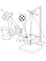
図1は、視覚センサのキャリブレーションに関し、特に複数のカメラを備えるステレオカメラを使用したキャリブレーションを実施するためのロボットシステム1000の全体の構成図である。
図1に示すように、ロボットシステム1000は、2台のカメラ(第1のカメラ21及び第2のカメラ22)を備えるステレオカメラ2と、ステレオカメラ2により撮像される画像データを画像処理して3次元計測を行う視覚センサ制御装置1と、先端部にターゲットマーク5が取り付けられたアーム41を有するロボット4と、ロボット4を制御するロボット制御装置3と、を備える。ステレオカメラを構成するカメラは2台に限らず、2台以上であればよい。また、ステレオカメラを構成するそれぞれのカメラは単一のカメラとしても使用できることは言うまでもない。
Hereinafter, an example of the embodiment of the present invention will be described.
In this embodiment, a visual sensor control device is illustrated as a calibration device.
FIG. 1 is a general block diagram of a
As shown in FIG. 1, the
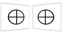
図2A及び図2Bは、ステレオカメラ2の配置状態を示す図である。ステレオカメラ2は、架台(図示せず)に固定される。第1のカメラ21及び第2のカメラ22は、図2Aに示すように平行に配置してもよい。また、図2Bに示すように、第1のカメラ21及び第2のカメラ22をそれぞれ傾けて配置してもよい。
なお、第1のカメラ21及び第2のカメラ22をそれぞれ傾けて配置することで、第1のカメラ21及び第2のカメラ22を平行に配置する場合に比較して、第1のカメラ21による撮像領域と第2のカメラ22による撮像領域との重なり領域を大きくとることが可能となる。すなわち、ステレオカメラ2による3次元計測の可能な領域を、第1のカメラ21及び第2のカメラ22を平行に配置する場合に比較して、大きくとることができる。
逆に、第1のカメラ21及び第2のカメラ22をそれぞれ傾けて配置することで、第1のカメラ21及び第2のカメラ22を平行に配置する場合に比較して、第1のカメラ21により撮像される対象物(ターゲットマーク5)と第2のカメラ22により撮像される対象物(ターゲットマーク5)の画像上の歪みの差が大きくなる。
なお、第1のカメラ21及び第2のカメラ22の視野範囲、レンズ等を同じ構成にすることが望ましい。そうすることで、ターゲットマーク5の見え方が同じようになることが期待できる。
FIGS. 2A and 2B are diagrams showing the arrangement of the
Note that by arranging the
On the contrary, by arranging the
In addition, it is desirable to make the visual field range of the
図3は、ターゲットマーク5の一例を示す図である。ターゲットマーク5は、この例に限定されない。ターゲットマーク5は任意の形状のものを使用できる。ただし、モデルパターンとして使用するターゲットマーク5の特徴が2次元平面上にあるようにすることが望ましい。
ターゲットマーク5として、例えば、紙やシールに印刷したものをロボット4のアームの先端に貼り付けるようにしてもよい。
アーム41の先端部分に取り付けられたターゲットマーク5について、ターゲットマーク5の3次元位置を計測する点が予め指定され、ロボット4の手先座標系における3次元での位置及び姿勢が予め求められているものとする。
図4にターゲットマーク5の3次元位置を計測する点Pの一例を示す。図4に示すように、ターゲットマーク5の3次元位置を計測する点Pを明示的に指定しない場合には、ターゲットマーク5の中心点を計測するようにしてもよい。
FIG. 3 is a view showing an example of the
As the
For the
FIG. 4 shows an example of a point P at which the three-dimensional position of the
図5A及び図5Bに複数のカメラにより撮像される対象物の画像上の歪みについて一例を示す。図5Aは、撮像される対象物の画像がそれぞれ、逆方向に歪んでいる例を示している。図5Bは、撮像される対象物の画像のサイズが異なるため、ターゲットマーク5が画像上で異なるサイズで映っている例を示している。 FIGS. 5A and 5B show an example of distortion on an image of an object captured by a plurality of cameras. FIG. 5A shows an example in which the images of the objects to be imaged are distorted in opposite directions. FIG. 5B shows an example in which the target marks 5 appear in different sizes on the image because the size of the image of the object to be imaged is different.
ロボット制御装置3はロボット座標系におけるアーム41の先端の座標位置を現在位置として認識する。したがって、ロボット座標系におけるアーム41の先端の座標位置と、ターゲットマーク5のロボット4の手先座標系における既知の3次元での位置及び姿勢と、に基づいてロボット制御装置3は、アーム41を駆動制御した時のターゲットマーク5のロボット座標系における座標位置を常に認識することができる。
ロボット制御装置3は、全体を統括制御するためのCPU(図示せず)を備え、外部機器インタフェース(図示せず)を介して、視覚センサ制御装置1が接続され、視覚センサ制御装置1にターゲットマーク5のロボット座標系における座標位置を送信したり、視覚センサ制御装置1における画像処理(例えば、ターゲットマーク5の検出処理等)によって得られた画像処理結果等を受信する。
The robot control device 3 recognizes the coordinate position of the tip of the
The robot control device 3 includes a CPU (not shown) for overall control of the whole, and the visual sensor control device 1 is connected via an external device interface (not shown), and the visual sensor control device 1 is targeted The coordinate position of the
ロボット制御装置3は、キャリブレーション実行時に、予め設定されたキャリブレーションする範囲(「キャリブレーション範囲」という)内でアーム41の先端に取り付けられたターゲットマーク5を移動させるようにアーム41を駆動制御する。この際、アーム41が設定されたキャリブレーション範囲を万遍なく移動することが望ましい。例えば、図6A又は図6Bに示す軌道をターゲットマーク5が移動するように制御してもよい。
The robot control device 3 drives and controls the
ここで、キャリブレーション範囲とは、アーム41の先端部分に取り付けられたターゲットマーク5をキャリブレーション時に移動させる空間であって、第1のカメラ21又は第2のカメラ22の少なくともいずれかのカメラの撮像範囲内(画角内)に、移動させたターゲットマーク5が撮像される、当該ターゲットマーク5の移動範囲を指す。図6Cにキャリブレーション範囲の一例を示す。
キャリブレーション範囲は、例えば、当該空間内の平面上に矩形で指定することができる。キャリブレーション範囲を矩形で指定する場合には、当該矩形の4隅のロボット座標系での座標位置を計測すればよい。また、アーム41の先端部分に取り付けられたターゲットマーク5が移動する空間上に障害物等が存在する場合には、当該障害物を避けるように、複数の線分により構成される閉じた図形によりキャリブレーション範囲を指定してもよい。
Here, the calibration range is a space for moving the
The calibration range can be specified, for example, as a rectangle on a plane in the space. When the calibration range is designated by a rectangle, the coordinate position in the robot coordinate system of the four corners of the rectangle may be measured. Also, when an obstacle or the like is present in the space in which the
また、ロボット制御装置3は、ロボット4のアーム41の先端に取り付けられたターゲットマーク5のロボット座標系における座標位置を計測する。すなわち、ターゲットマーク5の移動先のロボット座標系での座標位置を計測することができる。
Further, the robot control device 3 measures the coordinate position of the
視覚センサ制御装置1には、第1のカメラ21及び第2のカメラ22を備えるステレオカメラ2が接続されており、第1のカメラ21及び第2のカメラ22によりターゲットマーク5を撮像し、第1のカメラ21及び第2のカメラ22のキャリブレーションを行う。このように、本実施例においては、視覚センサ制御装置1がキャリブレーション装置の機能を果たす。
A
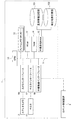
図7は、視覚センサ制御装置1の機能構成を示す機能ブロック図である。
視覚センサ制御装置1は、図7に示すように、全体を統括制御するためのCPU(中央演算処理装置)10を備えている。CPU10にはバス11を介して、複数のフレームメモリ12、ROM(読み出し専用メモリ)13、RAM(ランダムアクセスメモリ)14、不揮発性RAM15が接続されている。また、バス11には、カメラインタフェース16を介してステレオカメラ2(第1のカメラ21及び第2のカメラ22)が接続されると共に、モニタインタフェース17を介してモニタ19が接続されている。さらに、CPU10には、バス11を介して外部機器インタフェース18が接続されている。
FIG. 7 is a functional block diagram showing a functional configuration of the visual sensor control device 1.
As shown in FIG. 7, the visual sensor control device 1 includes a CPU (central processing unit) 10 for overall control of the whole. A plurality of
ROM13には、視覚センサ制御装置1で行われる様々な処理のためのプログラムが格納される。また、一般にRAMへのアクセスはROMへのアクセスよりも高速であることから、CPU10は、ROM13に格納されたプログラムを予めRAM14上に展開しておき、RAM14からプログラムを読み込んで実行してもよい。また、RAM14には、プログラムの実行時に必要な一時待避データが格納される。
不揮発性RAM15は、磁気記憶装置、フラッシュメモリ、MRAM、FRAM(登録商標)、EEPROM、又はバッテリでバックアップされるSRAM若しくはDRAM等であり、視覚センサ制御装置1の電源がオフされても記憶状態が保持される不揮発性メモリとして構成される。不揮発性RAM15には、プログラム実行時に必要な設定などが記憶される。
フレームメモリ12には画像データが格納される。
The
The
The
[モデルパターンについて]
不揮発性RAM15は、基準情報記憶部151と、検出結果記憶部152と、を備える。
基準情報記憶部151は、対象物(ターゲットマーク5)を表す基準情報(「モデルパターン」又は「テンプレート」ともいう)を記憶する。基準情報としては、例えば対象物(ターゲットマーク5)のエッジ点からなる集合(「エッジ点群」ともいう)を採用してもよい。エッジ点とは、画像上での輝度変化が大きな点である。
例えば、対象物(ターゲットマーク5)に公知のSobelフィルタをかけてエッジ画像へ変換し、エッジ画像中から予め定められた閾値以上の強度を有する画素(エッジ点)を抽出し、エッジ点群とすることができる。このように、検出すべき対象物(ターゲットマーク5)を含む画像から抽出したエッジ点群をモデルパターンとして基準情報記憶部221に記憶しておく。
なお、モデルパターンはエッジ点に限定されない。例えば、公知のSIFTのような特徴点を使用してもよい。また、対象物(ターゲットマーク5)の輪郭線に合うように線分、矩形、円などの幾何図形を配置することでモデルパターンを生成してもよい。その場合、輪郭線を構成する幾何図形上に適当な間隔で特徴点を設ければよい。または、モデルパターンは、ターゲットマーク5を撮像した画像からモデルパターン指定領域の箇所を切り抜いたテンプレート画像でもよい。
また、前述したように、アーム41の先端に取り付けられたターゲットマーク5の3次元位置を計測する点Pが予め指定され、ロボット4の手先座標系における3次元での位置及び姿勢を予め求められているものとする。
このように生成されたモデルパターンを基準情報記憶部151に予め記憶することを、「モデルパターンを教示する」ともいう。
モデルパターンの教示については後述する。
[About model pattern]
The
The reference
For example, a known Sobel filter is applied to an object (target mark 5) to convert it into an edge image, and a pixel (edge point) having an intensity equal to or more than a predetermined threshold is extracted from the edge image. can do. As described above, the edge point group extracted from the image including the target object (target mark 5) to be detected is stored in the reference information storage unit 221 as a model pattern.
The model pattern is not limited to edge points. For example, known SIFT-like feature points may be used. Alternatively, the model pattern may be generated by arranging geometric figures such as line segments, rectangles, and circles so as to fit the outline of the object (target mark 5). In that case, feature points may be provided at appropriate intervals on the geometric figure that constitutes the outline. Alternatively, the model pattern may be a template image obtained by cutting out a part of a model pattern designation area from an image obtained by imaging the
Also, as described above, the point P at which the three-dimensional position of the
Storing the model pattern generated in this manner in the reference
The teaching of the model pattern will be described later.
検出結果記憶部152は、ターゲットマーク5を設定されたキャリブレーションする範囲を移動させた場合、それぞれの移動先において、教示されたモデルパターンを使用して第1のカメラ21及び第2のカメラ22により撮像される画像データからターゲットマーク5を検出した結果を記憶する。
When the detection
第1のカメラ21及び第2のカメラ22は、それぞれCPU10からの指令に従って、対象物を撮像して画像を取得し、取得した画像に関する信号を出力する。カメラインタフェース16は、CPU10からの指令に従って第1のカメラ21及び第2のカメラ22に対して露光のタイミングを制御するための同期信号を発生する機能や、第1のカメラ21及び第2のカメラ22から受信した信号を増幅する機能を有している。このような第1のカメラ21及び第2のカメラ22やカメラインタフェース16は市販される一般的なものであり、特に限定されるものではない。
The
第1のカメラ21及び第2のカメラ22から取り込まれた画像に関する信号は、カメラインタフェース16においてA/D変換され、バス11を介してディジタル画像データとしてフレームメモリ12に一時的に格納される。視覚センサ制御装置1では、フレームメモリ12、ROM13、RAM14及び不揮発性RAM15に格納されているデータを用いてCPU10が画像処理を行い、画像処理の結果データが再度フレームメモリ12に格納される。CPU10は、指令により、フレームメモリ12に格納されているデータをモニタインタフェース17に転送してモニタ19上に表示させ、オペレータなどがデータの内容を確認することを可能にさせるようにしてもよい。
Signals relating to images taken from the
外部機器インタフェース18は様々な外部機器に接続される。例えば、外部機器インタフェース18にはロボット制御装置3が接続され、ロボット制御装置3からターゲットマーク5のロボット座標系における座標位置を受けたり、画像処理によって得られた位置情報データ等をロボット制御装置3に供給する。また、外部機器インタフェース18には、オペレータのための入力装置(図示せず)としてキーボードやマウスなどを接続してもよい。
The
次に、CPU10の有する機能を各処理部の観点から説明する。なお、各処理ステップ(方法)の観点に基づく説明は、「部」を「ステップ」に置き換えることで説明できるため、省略する。
図8は、視覚センサ制御装置1におけるCPU10の機能構成を示すブロック図である。
CPU10は、撮像制御部100と、モデルパターン生成部101と、第1パラメータ設定部102と、第1検出部103と、第2パラメータ設定部104と、第2検出部105と、キャリブレーション部106と、を備える。
これらの各機能部は、ROM13に格納されたシステムプログラムをCPU10が実行することにより実現される。
Next, the functions of the
FIG. 8 is a block diagram showing a functional configuration of the
The
Each of these functional units is realized by the
[撮像制御部100]
撮像制御部100は、ロボット4によりキャリブレーションする範囲内を移動させられるロボット4のアーム41の先端に取り付けられたターゲットマーク5を第1のカメラ及び第2のカメラにより撮像する。特に、キャリブレーション時にはターゲットマーク5を複数の移動先の位置で撮像する。ここで複数の移動先の個数としては、キャリブレーションができるだけの最小個数より大きな個数(例えば、20以上)とすることが望ましい。そうすることで、キャリブレーションの精度を高めることが可能となる。
[Imaging control unit 100]
The
[モデルパターン生成部101]
モデルパターン生成部101は、例えば第1のカメラ21により、モデルパターンを生成する。
図9にモデルパターンの一例を示す。また、図10にモデルパターンを生成するフローチャートを示す。モデルパターン生成部101は、図9に示すようなモデルパターンを生成する。図10を参照しながら、モデルパターン生成部101の機能を説明する。
[Model pattern generation unit 101]
The model
An example of a model pattern is shown in FIG. Further, FIG. 10 shows a flowchart for generating a model pattern. The model
ステップS1において、モデルパターン生成部101は、第1のカメラ21の視野内に配置されたターゲットマーク5を第1のカメラ21により撮像する制御を行う。なお、このときの第1のカメラ21とターゲットマーク5の位置関係は、ターゲットマーク5を検出するときと同じになるようにして行うことが望ましい。
In step S <b> 1, the model
ステップS2において、モデルパターン生成部101は、ターゲットマーク5を撮像した画像において、ターゲットマーク5が写った領域を矩形、円形等によりモデルパターン指定領域として設定するとともに、モデルパターン指定領域内にモデルパターン座標系を定義する。なお、モデルパターン生成部101は、オペレータにより指示された領域をモデルパターン指定領域として設定してもよい。また、モデルパターン生成部101が、画像における輝度勾配の大きい個所をターゲットマーク5の像の輪郭として算出して、当該ターゲットマーク5の像の輪郭を内部に含むように、モデルパターン指定領域を設定してもよい。
In
ステップS3において、モデルパターン生成部101は、モデルパターン指定領域内でエッジ点を特徴点として抽出し、エッジ点の位置、輝度勾配の方向、輝度勾配の大きさなどの物理量を求め、モデルパターン指定領域内に定義されたモデルパターン座標系で表現される値に変換する。
また、モデルパターン生成部101は、オペレータにより指示された点を、ターゲットマーク5の3次元位置を計測する点Pとして設定し、基準情報記憶部151に記憶する。なお、モデルパターン生成部101は、例えば、モデルパターンの中心点を、ターゲットマーク5の3次元位置を計測する点Pとして設定してもよい。
なお、前述したように、モデルパターンはエッジ点に限定されない。例えば、公知のSIFTのような特徴点を使用してもよい。また、対象物(ターゲットマーク5)の輪郭線に合うように線分、矩形、円などの幾何図形を配置することでモデルパターンを生成してもよい。その場合、輪郭線を構成する幾何図形上に適当な間隔で特徴点を設ければよい。または、モデルパターンは、ターゲットマーク5を撮像した画像からモデルパターン指定領域の箇所を切り抜いたテンプレート画像でもよい。
In step S3, the model
Further, the model
As described above, the model pattern is not limited to edge points. For example, known SIFT-like feature points may be used. Alternatively, the model pattern may be generated by arranging geometric figures such as line segments, rectangles, and circles so as to fit the outline of the object (target mark 5). In that case, feature points may be provided at appropriate intervals on the geometric figure that constitutes the outline. Alternatively, the model pattern may be a template image obtained by cutting out a part of a model pattern designation area from an image obtained by imaging the
ステップS4において、モデルパターン生成部101は、生成したモデルパターンを基準情報記憶部151に記憶する。
以上のように、モデルパターンは、一方のカメラ(第1のカメラ21)により撮像される画像を使って生成される。第2のカメラ22に対するモデルパターンとしては、第1のカメラにより撮像される画像を使って生成されたモデルパターンを流用する。
In step S4, the model
As described above, the model pattern is generated using an image captured by one camera (first camera 21). As a model pattern for the
次に、基準情報記憶部151に記憶されたモデルパターンを使用して、第1のカメラ21により撮像される画像データからターゲットマーク5を検出する際の問題点について説明する。
Next, problems in detecting the
キャリブレーション時において、第1のカメラ21によるターゲットマーク5の画像の撮影環境がそれぞれ異なることが想定される。撮影環境の違いとしては、例えば、移動先の位置の違いより第1のカメラ21とターゲットマーク5の相対位置関係が変わる。このため、第1のカメラ21によるアーム41の先端部分に取り付けられたターゲットマーク5の撮像される画像は、キャリブレーションする範囲内におけるターゲットマーク5の移動先によって、モデルパターン生成部101により生成されたモデルパターンとはその大きさが異なったり、明るさが異なったり、回転やひずみの生じたアピアランスの相違するものになることがある。このため、モデルパターンと完全に一致するものを検出しようとした場合、第1のカメラ21により撮像される画像データから対象物(ターゲットマーク5)を検出することができないという状況が発生しうる。
At the time of calibration, it is assumed that the shooting environments of the image of the
[第1パラメータ設定部102]
このような状況においても、第1のカメラ21により撮像される画像データから、キャリブレーションする範囲内におけるターゲットマーク5の移動先に関わらず、モデルパターンを検出することができるように、第1パラメータ設定部102は、第1のカメラ21により撮像される画像データからターゲットマーク5のモデルパターンを検出するための第1パラメータを設定する。
より具体的には、第1パラメータ設定部102により設定される第1パラメータは、検出アルゴリズムに依存するものであり、例えば、モデルに対するサイズ、回転、歪み、検出する位置の範囲、角度の範囲等の所定の範囲を有するように構成したり、単一の数値やオンオフ値で構成したりすることができる。なお、第1パラメータは、ここで例示したものに限らない。
そうすることで、ターゲットマーク5の移動先に関わらず、モデルパターンを検出することができるように、後述の第1検出部103は、撮像データから、単一の数値やオンオフ値又は所定の範囲内のパラメータの値でモデルパターンと一致するものを検出できるように構成する。そうすることで、適切なパラメータの値を適用することにより、撮像データからモデルパターンを検出することができる。
第1パラメータは、第1のカメラ21により撮像される画像データに適用されるパラメータとしてもよい。この場合、第1検出部103は、第1のカメラ21により撮像される画像データに第1パラメータを適用した画像データから、ターゲットマーク5のモデルパターンを検出するように構成される。例えば、画像データにガウシアンフィルタを掛けて平滑化した画像データからモデルパターンを検出できる。
また、第1パラメータは、ターゲットマーク5のモデルパターンに適用されるパラメータとしてもよい。この場合、第1検出部103は、第1のカメラ21により撮像される画像データから、第1パラメータを適用したモデルパターンによりターゲットマーク5を検出するように構成される。
[First parameter setting unit 102]
Even in such a situation, the first parameter is set so that the model pattern can be detected from the image data captured by the
More specifically, the first parameter set by the first
By doing so, regardless of the movement destination of the
The first parameter may be a parameter applied to image data captured by the
Further, the first parameter may be a parameter applied to the model pattern of the
第1パラメータ設定部102が設定する第1パラメータの一つとして、例えば、射影変換、アフィン変換、相似変換等の変換行列をモデルパターンに適用してもよい。
例えば、第1パラメータの値を単一の数値で構成した場合には、単一の変換行列を選択し、第1パラメータの値を所定の範囲を有するように構成した場合には、所定の範囲の変換行列を選択可能とするようにすることができる。具体的には、所定の範囲を有するように第1パラメータを構成したときには、例えば、射影変換行列の場合、1つの射影変換行列に基づいて、当該射影変換行列のそれぞれの要素との偏差が所定の閾値以下になるような射影変換行列をパラメータの範囲に含むように構成してもよいし、回転の場合には、1つの回転角度に基づいて、回転角度の範囲を設定してもよい。また、相似変換についても同様に、1つの相似比に基づいて、相似比の範囲を設定してもよい。
こうすることで、例えば、ターゲットマーク5の移動先が異なることによるターゲットマーク5のアピアランスの相違にロバストな検出を可能とすることができる。
なお、露光時間についても、例えば、第1のカメラ21とターゲットマーク5の置かれる平面との角度、照明との関係等により、パラメータの値を設定することが望ましい。
As one of the first parameters set by the first
For example, when the value of the first parameter is configured by a single numerical value, a single transformation matrix is selected, and when the value of the first parameter is configured to have a predetermined range, the predetermined range is selected. The transformation matrix of can be made selectable. Specifically, when the first parameter is configured to have a predetermined range, for example, in the case of a projective transformation matrix, the deviation from each element of the projective transformation matrix is predetermined based on one projective transformation matrix A projective transformation matrix that is equal to or less than the threshold of may be included in the range of parameters, or in the case of rotation, the range of rotation angles may be set based on one rotation angle. Similarly, the range of similarity ratios may be set based on one similarity ratio for similarity conversion as well.
By doing this, for example, it is possible to make a robust detection against the difference in the appearance of the
Also for the exposure time, it is desirable to set the value of the parameter based on, for example, the angle between the
[第1検出部103]
第1検出部103は、第1のカメラ21により撮像される画像データからターゲットマーク5を検出し、検出されたターゲットマーク5の第1のカメラ21の画像座標系における座標位置を計測する。
具体的には、第1検出部103は、単一の数値、オンオフ値又は第1パラメータの所定の範囲からパラメータを選択する。なお、パラメータを所定の範囲から選択する際には、例えば、パラメータ範囲の値のなかで中心となる値を最初に選択してもよい。その後、例えば、中心の値から、プラスマイナスの方にそれぞれ、ずらしながら、次のパラメータを選択するようにしてもよい。
[First detection unit 103]
The
Specifically, the
第1検出部103は、前述したように第1パラメータが第1のカメラ21による撮像される画像データに適用されるパラメータの場合、単一の数値、オンオフ値又はパラメータの所定の範囲からパラメータを選択した後に、第1のカメラ21により撮像される画像データからターゲットマーク5を検出することができるように、当該パラメータにより、画像データを変換する。そうすることで、第1検出部103は、公知の検出手法により、変換後の画像データからターゲットマーク5を検出することができる。
In the case where the first parameter is a parameter applied to image data captured by the
具体的には、第1検出部103は、第1パラメータを適用した画像データから、教示されたモデルパターンの特徴点を抽出したのと同じ方法で特徴点を抽出し、特徴点とモデルパターンを構成する特徴点との間で公知のマッチングを行うことで、ターゲットマーク5を検出する。
Specifically, the
また、逆に、第1検出部103は、ターゲットマーク5のモデルパターンを当該パラメータにより変換するようにしてもよい。この場合、第1検出部103は、前述した公知の検出手法により、撮像データから変換後のモデルパターンと一致するターゲットマーク5を検出することができる。
具体的には、第1検出部103は、第1のカメラ21によって撮像される画像データから、教示されたモデルパターンの特徴点を抽出したのと同じ方法で特徴点を抽出し、特徴点と当該パラメータを適用したモデルパターンの特徴点との間で公知のマッチングを行うことで、ターゲットマーク5を検出する。
第1検出部103は、検出されたターゲットマーク5の第1のカメラ21の画像座標系における座標位置を計測する。
Also, conversely, the
Specifically, the
The
[第2パラメータ設定部104]
次に、第1のカメラ21により生成されたターゲットマーク5のモデルパターンを使用して、第2のカメラ22により撮像される画像データから当該モデルパターンを検出するための第2パラメータを設定する第2パラメータ設定部104について説明する。
第2パラメータ設定部104は、第2のカメラ22による撮像される画像データからターゲットマーク5のモデルパターンを検出するための第2パラメータを第1パラメータ設定部102により設定された第1パラメータに基づいて設定する。
より具体的には、第2パラメータ設定部104は、第2パラメータの値を初期設定する際に第1パラメータをそのまま使用する。
または、第2パラメータの値を初期設定する際に、例えば、第2パラメータを所定の範囲とする場合には、第2パラメータ設定部104は、第1パラメータの範囲と同一の範囲を設定したり、第2パラメータの範囲が、第1パラメータ設定部102により設定される第1パラメータの所定の範囲を含む広い範囲として設定することができる。このような場合には、後述する第2検出部105により、ある第2パラメータの値を適用することで、第2のカメラ22により撮像される画像データからターゲットマーク5のモデルパターンを検出することができた場合、第2パラメータ設定部104は、当該第2パラメータを中心として、第1パラメータの所定の範囲における中心値からの偏差に基づいて、第2パラメータの値の範囲を設定し直すことができる。
例えば、第1のカメラ21に対して第1パラメータにより、サイズの範囲を0.9から1.1に設定していた場合、中心値は1.0であって、第1パラメータの所定の範囲における中心値からの偏差は0.1となる。
他方、第2のカメラ22の対象物(ターゲットマーク5)について、第2のカメラ22において第2パラメータにおけるサイズを0.95とすることで対象物(ターゲットマーク5)を最初に検出することができた場合、第2パラメータの中心値を0.95とし、第1パラメータの偏差を第2パラメータに指定する。すなわち、第2パラメータの値の範囲は、中心値を0.95とする範囲[0.85〜1.05]に設定する。
このように、第2パラメータの値の範囲を初期設定時の範囲を見直すことが可能となり、第2のカメラ22の撮像データからのモデルパターンの検出をより効率的に実施することが可能となる。
[Second parameter setting unit 104]
Next, using a model pattern of the
The second
More specifically, the second
Alternatively, when initially setting the value of the second parameter, for example, in the case where the second parameter is set as the predetermined range, the second
For example, when the size range is set to 0.9 to 1.1 by the first parameter with respect to the
On the other hand, for the object of the second camera 22 (target mark 5), the object (target mark 5) may be detected first by setting the size in the second parameter to 0.95 in the
Thus, it is possible to review the range of the value of the second parameter at the time of initial setting, and it is possible to more efficiently detect the model pattern from the imaging data of the
[第2検出部105]
第2検出部105は、第2のカメラ22により撮像される画像データからターゲットマークのモデルパターンを検出し、検出されたターゲットマーク5の第2のカメラ22の画像座標系における座標位置を計測する。
なお、第2検出部105の検出処理については、前述した第1検出部103の検出処理の説明において、第1のカメラ21、第1パラメータ設定部102及び第1パラメータをそれぞれ、第2のカメラ22、第2パラメータ設定部104、及び第2パラメータに読み替えることで説明できるため、省略する。
[Second detection unit 105]
The
In the detection process of the
[キャリブレーション部106]
キャリブレーション部106は、ロボット制御装置3により移動させられた、ロボット4のアーム41の先端に取り付けられたターゲットマーク5の複数の移動先における、第1のカメラ21により撮像される画像データ中のターゲットマーク5の第1のカメラ21の画像座標系における座標位置と、第2のカメラ22により撮像される画像データ中のターゲットマーク5の第2のカメラ22の画像座標系における座標位置と、第1のカメラ21又は第2のカメラ22により撮像される時のターゲットマーク5のロボット座標系における座標位置と、を検出結果記憶部152に記憶する。
キャリブレーション部106は、検出結果記憶部152に記憶された、ターゲットマーク5の第1のカメラ21の画像座標系における座標位置と、ターゲットマーク5の第2のカメラ22の画像座標系における座標位置と、第1のカメラ21及び第2のカメラ22により撮像される時のターゲットマーク5のロボット座標系における座標位置と、に基づいて第1のカメラ21及び第2のカメラ22のキャリブレーションを行う。第1のカメラ21と第2のカメラ22は個別にキャリブレーションできることは言うまでもない。
[Calibration unit 106]
The
The
図11は、本実施形態に係る第1のカメラ21及び第2のカメラ22を備えるステレオカメラ2のキャリブレーション処理における視覚センサ制御装置1(CPU10)の処理を示すフローチャートである。なお、キャリブレーションする範囲は予め設定されているものとする。
FIG. 11 is a flowchart showing processing of the visual sensor control device 1 (CPU 10) in the calibration processing of the
ステップS11において、CPU10(モデルパターン生成部101)は、オペレータの操作により、第1のカメラ21によりモデルパターンを生成する。
In step S11, the CPU 10 (model pattern generation unit 101) generates a model pattern by the
ステップS12において、CPU10(第1パラメータ設定部102)は、オペレータの指定により、第1のカメラ21に対する第1パラメータを設定する。
In step S12, the CPU 10 (first parameter setting unit 102) sets a first parameter for the
ステップS13において、CPU10(第2パラメータ設定部104)は、第2のカメラ22による撮像される画像データからターゲットマーク5のモデルパターンを検出するための第2パラメータを第1パラメータ設定部102により設定された第1パラメータに基づいて設定する。
In step S13, the CPU 10 (the second parameter setting unit 104) sets the second parameter for detecting the model pattern of the
ステップS14において、CPU10(キャリブレーション部106)は、計測回数をカウントするための計測カウンタに1を設定する。 In step S14, the CPU 10 (calibration unit 106) sets 1 in the measurement counter for counting the number of times of measurement.
ステップS15において、CPU10(キャリブレーション部106)は、ロボット制御装置3により計測されたターゲットマーク5のロボット座標系における3次元座標位置を取得する。
In step S <b> 15, the CPU 10 (calibration unit 106) acquires a three-dimensional coordinate position of the
ステップS16において、CPU10(第1検出部103)は、第1のカメラ21により撮像される画像データから、ターゲットマーク5を検出し、検出されたターゲットマーク5の第1のカメラ21の画像座標系における座標位置を計測する。
In step S16, the CPU 10 (first detection unit 103) detects the
ステップS17において、CPU10(第2検出部105)は、第2のカメラ22により撮像される画像データから、ターゲットマーク5を検出し、検出されたターゲットマーク5の第2のカメラ22の画像座標系における座標位置を計測する。
In step S17, the CPU 10 (the second detection unit 105) detects the
ステップS18において、CPU10(キャリブレーション部106)は、現在位置におけるターゲットマーク5のロボット座標系における3次元座標位置、第1のカメラ21の画像座標系における座標位置、及び第2のカメラ22の画像座標系における座標位置を関係付ける。
In step S18, the CPU 10 (calibration unit 106) determines the three-dimensional coordinate position of the
ステップS19において、CPU10(キャリブレーション部106)は、計測回数をカウントするための計測カウンタに1を加算する。 In step S19, the CPU 10 (calibration unit 106) adds 1 to the measurement counter for counting the number of times of measurement.
ステップS20において、計測カウンタが所定の値を超えない場合(No)、ステップS21に移る。計測カウンタが所定の値を超える場合(Yes)、ステップS22に移る。 In step S20, when the measurement counter does not exceed the predetermined value (No) , the process proceeds to step S21. If the measurement counter exceeds the predetermined value (Yes), the process proceeds to step S22 .
ステップS21において、ロボット制御装置3は、ロボット4のアーム41の先端に取り付けられたターゲットマーク5を、予め設定されたキャリブレーションする範囲内の第1のカメラ21又は第2のカメラ22から計測できる場所に移動する。その後、ステップS15に移る。
In step S21, the robot control device 3 can measure the
ステップS22において、CPU10(キャリブレーション部106)は、ステップ18において記憶された、ターゲットマーク5のロボット座標系における3次元座標位置、第1のカメラ21の画像座標系における座標位置及び第2のカメラ22の画像座標系における座標位置の関係に基づいて、第1のカメラ21と第2のカメラ22のキャリブレーションを実行する。
In step S22, the CPU 10 (calibration unit 106) stores the three-dimensional coordinate position of the
なお、本処理フローは一例であり、これに限定されない。 The present processing flow is an example, and the present invention is not limited to this.
本実施形態によれば、視覚センサ制御装置1は、ロボット4により移動させられるロボット4に取り付けられたターゲットマーク5を、複数の移動先で第1のカメラ21及び第2のカメラ22により撮像する撮像制御部100と、第1のカメラ21による撮像される画像データからターゲットマーク5のモデルパターンを検出するための第1パラメータを設定する第1パラメータ設定部102と、第2のカメラ22による撮像される画像データからターゲットマーク5のモデルパターンを検出するための第2パラメータを第1パラメータ設定部102により設定された第1パラメータに基づいて設定する第2パラメータ設定部104と、を備える。
これにより、ステレオカメラ2のような複数のカメラをキャリブレーションする際に、例えば、第1のカメラ21に対してのみ、第1パラメータを設定し、第2のカメラ22に対しては、第2パラメータ設定部104により、第1パラメータに基づいて第2パラメータが設定されるため、複数のカメラ毎にモデルパターンの作成及びターゲットマークを検出するためのパラメータ設定を行わずに済むことができ、効率が向上する。
According to the present embodiment, the visual sensor control device 1 images the
Thus, when calibrating a plurality of cameras such as the
ターゲットマーク5は、ロボット4のアーム先端に取り付けられ、ロボット4の手先座標系における3次元での位置及び姿勢が予め求められる。
これにより、種々のターゲットマーク5を検出することができる。
The
Thereby,
第1パラメータ及び第2パラメータは、単一の数値、オンオフ値、又は範囲を有するパラメータを含む。
これにより、種々のターゲットマーク5を検出することができる。
The first parameter and the second parameter include parameters having a single numerical value, an on-off value, or a range.
Thereby,
第2パラメータ設定部104により初期設定される第2パラメータは、第1パラメータ設定部102により設定される第1パラメータで第1のカメラ21により撮像される画像データから検出できるターゲットマークは全て、第2のカメラ22により撮像される画像から検出できるように設定される。
これにより、種々のターゲットマーク5を検出することができる。
The second parameter is initialized by the second
Thereby,
第2パラメータ設定部104は、第1パラメータが所定の範囲を有する場合には、第2パラメータの範囲として、第2のカメラ22により撮像される画像データからターゲットマーク5を検出することができたときに用いた当該第2パラメータの値を中心として、当該第1パラメータの所定の範囲における中心値からの偏差の大きさの範囲に設定する。
これにより、第2のカメラ22により撮像される画像データからロボット4に取り付けられたターゲットマーク5を検出する処理を効率化することができる。
When the first parameter has a predetermined range, the second
As a result, the process of detecting the
また、第1パラメータ及び第2パラメータは、それぞれ、ターゲットマーク5のモデルパターン、サイズ、及び変形に関するパラメータを含む。
これにより、第2のカメラ22により撮像される画像データからロボット4に取り付けられたターゲットマーク5を検出する処理を効率化することができる。
In addition, the first parameter and the second parameter respectively include parameters related to the model pattern, the size, and the deformation of the
As a result, the process of detecting the
また、第1パラメータ及び第2パラメータは、それぞれターゲットマーク5のモデルパターンに適用されるパラメータとすることができる。
また、第1パラメータ及び第2パラメータは、それぞれ第1のカメラ21による撮像される画像データ及び第1のカメラ21による撮像される画像データに適用されるパラメータとすることができる。
これにより、種々のターゲットマーク5を検出することができる。
Also, the first parameter and the second parameter can be parameters to be applied to the model pattern of the
The first parameter and the second parameter may be parameters applied to image data captured by the
Thereby,
本実施形態におけるキャリブレーション方法は、ロボット4により移動させられるロボット4に取り付けられたターゲットマーク5を、複数の移動先で第1のカメラ21及び第2のカメラ22により撮像する撮像制御ステップと、第1のカメラ21による撮像される画像データからターゲットマーク5のモデルパターンを検出するための第1パラメータを設定する第1パラメータ設定ステップと、第2のカメラ22による撮像される画像データからターゲットマーク5のモデルパターンを検出するための第2パラメータを第1パラメータ設定ステップにより設定された第1パラメータに基づいて設定する第2パラメータ設定ステップと、を備える。
これにより、視覚センサ制御装置1と同様の効果を奏する。
The calibration method in the present embodiment includes an imaging control step of imaging the
Thereby, the same effect as the visual sensor control device 1 is obtained.
本実施形態におけるプログラムはロボット4により移動させるロボット4に取り付けられたターゲットマーク5を、複数の移動先で第1のカメラ21及び第2のカメラ22により撮像する撮像制御ステップと、第1のカメラ21により撮像される画像データからターゲットマーク5を検出するための第1パラメータを設定する第1パラメータ設定ステップと、第2のカメラ22により撮像される画像データからターゲットマーク5を検出するための第2パラメータを第1パラメータ設定ステップにより設定された第1パラメータに基づいて設定する第2パラメータ設定ステップをコンピュータに実行させる。
これにより、視覚センサ制御装置1と同様の効果を奏する。
The program according to the present embodiment includes an imaging control step of imaging the
Thereby, the same effect as the visual sensor control device 1 is obtained.
以上、本発明の実施形態について説明したが、本発明は前述した実施形態に限るものではない。また、本実施形態に記載された効果は、本発明から生じる最も好適な効果を列挙したに過ぎず、本発明による効果は、本実施形態に記載されたものに限定されるものではない。
本実施形態においては、キャリブレーション装置として、視覚センサ制御装置1を適用したが、これに限定されない。視覚センサ制御装置1とロボット制御装置3とを一体とする制御装置として、キャリブレーション装置としてもよい。また、キャリブレーション装置として、情報処理装置(コンピュータ)全般を指すことができる。キャリブレーション装置には、例えば、サーバ、PC、各種制御装置などを適用してもよい。
As mentioned above, although embodiment of this invention was described, this invention is not limited to embodiment mentioned above. Further, the effects described in the present embodiment only list the most preferable effects arising from the present invention, and the effects according to the present invention are not limited to those described in the present embodiment.
In this embodiment, although vision sensor control device 1 was applied as a calibration device, it is not limited to this. A calibration device may be used as a control device in which the visual sensor control device 1 and the robot control device 3 are integrated. In addition, the information processing apparatus (computer) can be generally referred to as a calibration apparatus. For example, a server, a PC, various control devices, etc. may be applied to the calibration device.
視覚センサ制御装置1によるキャリブレーション方法は、ソフトウェアにより実現される。ソフトウェアによって実現される場合には、このソフトウェアを構成するプログラムが、コンピュータ(視覚センサ制御装置1)にインストールされる。また、これらのプログラムは、リムーバブルメディアに記録されてユーザに配布されてもよいし、ネットワークを介してユーザのコンピュータにダウンロードされることにより配布されてもよい。 The calibration method by the visual sensor control device 1 is realized by software. When implemented by software, a program configuring this software is installed in a computer (vision sensor control device 1). Also, these programs may be recorded on removable media and distributed to users, or may be distributed by being downloaded to a user's computer via a network.
1000 ロボットシステム
1 視覚センサ制御装置
10 CPU
100 撮像制御部
101 モデルパターン生成部
102 第1パラメータ設定部
103 第1検出部
104 第2パラメータ設定部
105 第2検出部
106 キャリブレーション部
11 バス
12 フレームメモリ
13 ROM
14 RAM
15 不揮発性RAM
151 基準情報記憶部
152 検出結果記憶部
16 カメラインタフェース
17 モニタインタフェース
18 外部機器インタフェース
19 モニタ
2 ステレオカメラ
21 第1のカメラ
22 第2のカメラ
3 ロボット制御装置
4 ロボット
41 アーム
5 ターゲットマーク
1000 Robot System 1
100
14 RAM
15 Nonvolatile RAM
151 Reference
Claims (10)
ロボットに取り付けられたターゲットマークのモデルパターンを生成するモデルパターン生成部と、
前記モデルパターンに基づいて、前記第1のカメラにより撮像される画像データから前記ターゲットマークを検出するための第1パラメータを設定する第1パラメータ設定部と、
前記モデルパターンに基づいて、前記第2のカメラにより撮像される画像データから前記ターゲットマークを検出するための第2パラメータを前記第1パラメータ設定部により設定された前記第1パラメータに基づいて設定する第2パラメータ設定部と、
前記ロボットにより移動させられる前記ロボットに取り付けられたターゲットマークを、複数の移動先で前記第1のカメラ及び前記第2のカメラにより撮像する撮像制御部と、
前記第1パラメータの値を用いて、前記第1のカメラにより撮像される画像データから前記ターゲットマークを検出し、検出された前記ターゲットマークの前記第1のカメラの画像座標系における座標位置を計測する第1検出部と、
前記第2パラメータの値を用いて、前記第2のカメラにより撮像される画像データから前記ターゲットマークを検出し、検出された前記ターゲットマークの前記第2のカメラの画像座標系での座標位置を計測する第2検出部と、
前記第1検出部により計測された前記ターゲットマークの前記第1のカメラの画像座標系における座標位置と、前記第2検出部により計測された前記ターゲットマークの前記第2のカメラの画像座標系における座標位置と、前記第1のカメラ及び前記第2のカメラにより撮像される時の前記ターゲットマークの前記ロボット座標系における座標位置と、に基づいて前記第1のカメラ及び前記第2のカメラのキャリブレーションを行うキャリブレーション部と、
を備えるキャリブレーション装置。 At least one of position information in an image coordinate system of a first camera included in the stereo camera and position information in an image coordinate system of a second camera included in the stereo camera is associated with position information in a robot coordinate system of the robot A calibration device,
A model pattern generation unit that generates a model pattern of a target mark attached to a robot;
A first parameter setting unit configured to set a first parameter for detecting the target mark from image data captured by the first camera based on the model pattern;
A second parameter for detecting the target mark from the image data captured by the second camera is set based on the model pattern based on the first parameter set by the first parameter setting unit. A second parameter setting unit,
An imaging control unit configured to capture an image of a target mark attached to the robot, which is moved by the robot, with a plurality of moving destinations by the first camera and the second camera;
The target mark is detected from the image data captured by the first camera using the value of the first parameter, and the coordinate position of the detected target mark in the image coordinate system of the first camera is measured. A first detection unit to
The target mark is detected from the image data captured by the second camera using the value of the second parameter, and the coordinate position of the detected target mark in the image coordinate system of the second camera is calculated. A second detection unit to measure;
The coordinate position in the image coordinate system of the first camera of the target mark measured by the first detection unit and the image coordinate system of the second camera of the target mark measured by the second detection unit Calibration of the first camera and the second camera based on the coordinate position and the coordinate position of the target mark in the robot coordinate system when imaged by the first camera and the second camera Calibration unit to perform the
A calibration device comprising:
前記第1検出部は、
前記第1のカメラにより撮像される画像データから、前記第1パラメータを適用したモデルパターンによりターゲットマークを検出し、
前記第2検出部は、
前記第2のカメラにより撮像される画像データから、前記第2パラメータを適用したモデルパターンによりターゲットマークを検出する、請求項4乃至請求項6の何れか1項に記載のキャリブレーション装置。 The first parameter and the second parameter are parameters applied to a model pattern of the target mark, respectively.
The first detection unit is
A target mark is detected from the image data captured by the first camera by a model pattern to which the first parameter is applied,
The second detection unit is
The calibration apparatus according to any one of claims 4 to 6, wherein a target mark is detected from image data captured by the second camera based on a model pattern to which the second parameter is applied.
前記第1検出部は、
前記第1のカメラによる撮像される画像データに前記第1パラメータを適用した画像データから、前記ターゲットマークを検出し、
前記第2検出部は、
前記第2のカメラによる撮像される画像データに前記第2パラメータを適用した画像データから、前記ターゲットマークを検出する、請求項1乃至請求項6の何れか1項に記載のキャリブレーション装置。 The first parameter and the second parameter are parameters applied to image data captured by the first camera and image data captured by the second camera, respectively.
The first detection unit is
Detecting the target mark from image data in which the first parameter is applied to image data captured by the first camera;
The second detection unit is
The calibration apparatus according to any one of claims 1 to 6, wherein the target mark is detected from image data in which the second parameter is applied to image data captured by the second camera.
前記キャリブレーション装置により、
ロボットに取り付けられたターゲットマークのモデルパターンを生成するモデルパターン生成ステップと、
前記モデルパターンに基づいて、前記第1のカメラにより撮像される画像データから前記ターゲットマークを検出するための第1パラメータを設定する第1パラメータ設定ステップと、
前記モデルパターンに基づいて、前記第2のカメラにより撮像される画像データから前記ターゲットマークを検出するための第2パラメータを前記第1パラメータ設定ステップにより設定された前記第1パラメータに基づいて設定する第2パラメータ設定ステップと、
前記ロボットにより移動させられる前記ロボットに取り付けられたターゲットマークを、複数の移動先で前記第1のカメラ及び前記第2のカメラにより撮像する撮像制御ステップと、
前記第1パラメータの値を用いて、前記第1のカメラにより撮像される画像データから前記ターゲットマークを検出し、検出された前記ターゲットマークの前記第1のカメラの画像座標系における座標位置を計測する第1検出ステップと、
前記第2パラメータの値を用いて、前記第2のカメラにより撮像される画像データから前記ターゲットマークを検出し、検出された前記ターゲットマークの前記第2のカメラの画像座標系における座標位置を計測する第2検出ステップと、
前記第1検出ステップにより計測された前記ターゲットマークの前記第1のカメラの画像座標系における座標位置と、前記第2検出ステップにより計測された前記ターゲットマークの前記第2のカメラの画像座標系における座標位置と、前記第1のカメラ及び前記第2のカメラにより撮像される時の前記ターゲットマークの前記ロボット座標系における座標位置と、に基づいて前記第1のカメラ及び前記第2のカメラのキャリブレーションを行うキャリブレーションステップと、
を備えるキャリブレーション方法。 Calibration that associates positional information in the image coordinate system of the first camera with which the stereo camera is provided with positional information in the image coordinate system of the second camera with the stereo camera with positional information in the robot coordinate system of the robot The calibration method by the device,
The calibration device
A model pattern generation step of generating a model pattern of a target mark attached to a robot;
A first parameter setting step of setting a first parameter for detecting the target mark from image data captured by the first camera based on the model pattern;
A second parameter for detecting the target mark from the image data captured by the second camera is set based on the model pattern, based on the first parameter set in the first parameter setting step. A second parameter setting step,
An imaging control step of imaging a target mark attached to the robot moved by the robot with a plurality of moving destinations by the first camera and the second camera;
The target mark is detected from the image data captured by the first camera using the value of the first parameter, and the coordinate position of the detected target mark in the image coordinate system of the first camera is measured. A first detection step to
The target mark is detected from the image data captured by the second camera using the value of the second parameter, and the coordinate position of the detected target mark in the image coordinate system of the second camera is measured. A second detection step to
The coordinate position in the image coordinate system of the first camera of the target mark measured in the first detection step, and in the image coordinate system of the second camera of the target mark measured in the second detection step Calibration of the first camera and the second camera based on the coordinate position and the coordinate position of the target mark in the robot coordinate system when imaged by the first camera and the second camera Calibration steps to perform the
A calibration method comprising:
前記モデルパターンに基づいて、第1のカメラにより撮像される画像データから前記ターゲットマークを検出するための第1パラメータを設定する第1パラメータ設定ステップと、
前記モデルパターンに基づいて、第2のカメラにより撮像される画像データから前記ターゲットマークを検出するための第2パラメータを前記第1パラメータ設定ステップにより設定された前記第1パラメータに基づいて設定する第2パラメータ設定ステップと、
前記ロボットにより移動させられる前記ロボットに取り付けられたターゲットマークを、複数の移動先で前記第1のカメラ及び前記第2のカメラにより撮像する撮像制御ステップと、
前記第1パラメータの値を用いて、前記第1のカメラにより撮像される画像データから前記ターゲットマークを検出し、検出された前記ターゲットマークの前記第1のカメラの画像座標系における座標位置を計測する第1検出ステップと、
前記第2パラメータの値を用いて、前記第2のカメラにより撮像される画像データから前記ターゲットマークを検出し、検出された前記ターゲットマークの前記第2のカメラの画像座標系における座標位置を計測する第2検出ステップと、
前記第1検出ステップにより計測された前記ターゲットマークの前記第1のカメラの画像座標系における座標位置と、前記第2検出ステップにより計測された前記ターゲットマークの前記第2のカメラの画像座標系における座標位置と、前記第1のカメラ及び前記第2のカメラにより撮像される時の前記ターゲットマークのロボット座標系における座標位置と、に基づいて前記第1のカメラ及び前記第2のカメラのキャリブレーションを行うキャリブレーションステップと、をコンピュータに実行させるためのプログラム。 A model pattern generation step of generating a model pattern of a target mark attached to a robot;
A first parameter setting step of setting a first parameter for detecting the target mark from image data captured by a first camera based on the model pattern;
A second parameter for detecting the target mark from image data captured by a second camera based on the model pattern is set based on the first parameter set in the first parameter setting step. 2 parameter setting step,
An imaging control step of imaging a target mark attached to the robot moved by the robot with a plurality of moving destinations by the first camera and the second camera;
The target mark is detected from the image data captured by the first camera using the value of the first parameter, and the coordinate position of the detected target mark in the image coordinate system of the first camera is measured. A first detection step to
The target mark is detected from the image data captured by the second camera using the value of the second parameter, and the coordinate position of the detected target mark in the image coordinate system of the second camera is measured. A second detection step to
The coordinate position in the image coordinate system of the first camera of the target mark measured in the first detection step, and in the image coordinate system of the second camera of the target mark measured in the second detection step Calibration of the first camera and the second camera based on the coordinate position and the coordinate position in the robot coordinate system of the target mark when imaged by the first camera and the second camera A program for making a computer execute a calibration step.
Priority Applications (4)
| Application Number | Priority Date | Filing Date | Title |
|---|---|---|---|
| JP2017003664A JP6527178B2 (en) | 2017-01-12 | 2017-01-12 | Vision sensor calibration device, method and program |
| US15/861,851 US10434654B2 (en) | 2017-01-12 | 2018-01-04 | Calibration device, calibration method, and computer readable medium for visual sensor |
| DE102018200155.3A DE102018200155B4 (en) | 2017-01-12 | 2018-01-08 | Calibration device, calibration method and program for a visual sensor |
| CN201810023848.4A CN108297096B (en) | 2017-01-12 | 2018-01-10 | Calibration device, calibration method, and computer-readable medium |
Applications Claiming Priority (1)
| Application Number | Priority Date | Filing Date | Title |
|---|---|---|---|
| JP2017003664A JP6527178B2 (en) | 2017-01-12 | 2017-01-12 | Vision sensor calibration device, method and program |
Publications (2)
| Publication Number | Publication Date |
|---|---|
| JP2018111165A JP2018111165A (en) | 2018-07-19 |
| JP6527178B2 true JP6527178B2 (en) | 2019-06-05 |
Family
ID=62782207
Family Applications (1)
| Application Number | Title | Priority Date | Filing Date |
|---|---|---|---|
| JP2017003664A Active JP6527178B2 (en) | 2017-01-12 | 2017-01-12 | Vision sensor calibration device, method and program |
Country Status (4)
| Country | Link |
|---|---|
| US (1) | US10434654B2 (en) |
| JP (1) | JP6527178B2 (en) |
| CN (1) | CN108297096B (en) |
| DE (1) | DE102018200155B4 (en) |
Families Citing this family (28)
| Publication number | Priority date | Publication date | Assignee | Title |
|---|---|---|---|---|
| JP6812095B2 (en) * | 2015-10-22 | 2021-01-13 | キヤノン株式会社 | Control methods, programs, recording media, robotic devices, and manufacturing methods for articles |
| CN110463182B (en) | 2017-03-31 | 2021-07-13 | 松下知识产权经营株式会社 | Imaging system and correction method |
| JP7203356B2 (en) * | 2017-03-31 | 2023-01-13 | パナソニックIpマネジメント株式会社 | Imaging system |
| JP6886620B2 (en) * | 2017-08-09 | 2021-06-16 | オムロン株式会社 | Calibration method, calibration system and program |
| JP7062911B2 (en) * | 2017-10-11 | 2022-05-09 | セイコーエプソン株式会社 | Robot system |
| WO2019225681A1 (en) * | 2018-05-23 | 2019-11-28 | パナソニックIpマネジメント株式会社 | Calibration device and calibration method |
| US20210215811A1 (en) * | 2018-07-06 | 2021-07-15 | Brain Corporation | Systems, methods and apparatuses for calibrating sensors mounted on a device |
| WO2020024909A1 (en) * | 2018-08-02 | 2020-02-06 | 广东虚拟现实科技有限公司 | Positioning and tracking method, terminal device, and computer readable storage medium |
| US11065768B2 (en) * | 2018-11-01 | 2021-07-20 | TE Connectivity Services Gmbh | Automatic calibration for camera-robot system with tool offsets |
| JP6863954B2 (en) * | 2018-11-14 | 2021-04-21 | ファナック株式会社 | Camera calibration device and camera calibration method |
| TWI677413B (en) | 2018-11-20 | 2019-11-21 | 財團法人工業技術研究院 | Calibration method and device for robotic arm system |
| CN109615662A (en) * | 2018-12-04 | 2019-04-12 | 中冶赛迪工程技术股份有限公司 | A kind of coordinate system scaling method, system, computer readable storage medium and equipment |
| TWI672206B (en) * | 2018-12-19 | 2019-09-21 | 財團法人工業技術研究院 | Method and apparatus of non-contact tool center point calibration for a mechanical arm, and a mechanical arm system with said calibration function |
| CN109262659B (en) * | 2018-12-20 | 2019-04-02 | 中国铁建重工集团有限公司 | A kind of zero adjustment method and apparatus of joint of mechanical arm sensor |
| KR102577448B1 (en) * | 2019-01-22 | 2023-09-12 | 삼성전자 주식회사 | Hand eye calibration method and system |
| WO2020157875A1 (en) * | 2019-01-30 | 2020-08-06 | 株式会社Fuji | Work coordinate generation device |
| DE102019107964B3 (en) | 2019-03-28 | 2020-08-06 | Franka Emika Gmbh | Projection device for a robot manipulator |
| JP7007324B2 (en) * | 2019-04-25 | 2022-01-24 | ファナック株式会社 | Image processing equipment, image processing methods, and robot systems |
| EP3738725B1 (en) | 2019-05-15 | 2022-02-16 | Omron Corporation | Measurement system, measurement device, measurement method, and measurement program |
| WO2020235541A1 (en) * | 2019-05-20 | 2020-11-26 | 国立大学法人東京大学 | Image interface device, image manipulation device, manipulation-object manipulation device, manipulation-object manipulation system, manipulation-object presentation method, and manipulation-object presentation program |
| CN110378898B (en) * | 2019-07-26 | 2021-07-16 | 金瓜子科技发展(北京)有限公司 | Beacon positioning method, device, storage medium and equipment |
| EP4092377A1 (en) * | 2020-01-14 | 2022-11-23 | Kyocera Corporation | Image processing device, imaging device, information processing device, detection device, roadside device, image processing method, and calibration method |
| CN111546328B (en) * | 2020-04-02 | 2022-06-24 | 天津大学 | Hand-eye calibration method based on three-dimensional vision measurement |
| CN112720470B (en) * | 2020-12-18 | 2022-05-13 | 南京中科煜宸激光技术有限公司 | Mechanical arm TCP manual rapid calibration device and method for additive machining |
| CN112710662A (en) * | 2020-12-25 | 2021-04-27 | 深圳中科飞测科技股份有限公司 | Generation method and device, generation system and storage medium |
| WO2023102647A1 (en) * | 2021-12-06 | 2023-06-15 | University Of Manitoba | Method for automated 3d part localization and adjustment of robot end-effectors |
| CN114734444B (en) * | 2022-04-27 | 2023-06-27 | 博众精工科技股份有限公司 | Target positioning method and device, electronic equipment and storage medium |
| DE102022003666A1 (en) | 2022-10-05 | 2023-01-26 | Mercedes-Benz Group AG | Method and device for calibrating tools of a robot in a production process |
Family Cites Families (34)
| Publication number | Priority date | Publication date | Assignee | Title |
|---|---|---|---|---|
| JP2690603B2 (en) * | 1990-05-30 | 1997-12-10 | ファナック株式会社 | Vision sensor calibration method |
| US5951475A (en) * | 1997-09-25 | 1999-09-14 | International Business Machines Corporation | Methods and apparatus for registering CT-scan data to multiple fluoroscopic images |
| JP4501239B2 (en) | 2000-07-13 | 2010-07-14 | ソニー株式会社 | Camera calibration apparatus and method, and storage medium |
| JP2002172575A (en) | 2000-12-07 | 2002-06-18 | Fanuc Ltd | Teaching device |
| DE10345743A1 (en) * | 2003-10-01 | 2005-05-04 | Kuka Roboter Gmbh | Method and device for determining the position and orientation of an image receiving device |
| US7693325B2 (en) * | 2004-01-14 | 2010-04-06 | Hexagon Metrology, Inc. | Transprojection of geometry data |
| DE102004024378B4 (en) | 2004-05-17 | 2009-05-20 | Kuka Roboter Gmbh | Method for robot-assisted measurement of objects |
| DE102004026814A1 (en) | 2004-06-02 | 2005-12-29 | Kuka Roboter Gmbh | Method and device for improving the positioning accuracy of a handling device |
| JP4267005B2 (en) * | 2006-07-03 | 2009-05-27 | ファナック株式会社 | Measuring apparatus and calibration method |
| US20090118864A1 (en) * | 2007-11-01 | 2009-05-07 | Bryce Eldridge | Method and system for finding a tool center point for a robot using an external camera |
| EP2075096A1 (en) | 2007-12-27 | 2009-07-01 | Leica Geosystems AG | Method and system for extremely precise positioning of at least one object in the end position of a space |
| US8229595B2 (en) * | 2008-06-19 | 2012-07-24 | Seelinger Michael J | Method and system for providing autonomous control of a platform |
| US8265376B2 (en) * | 2008-07-21 | 2012-09-11 | Cognitens Ltd. | Method and system for providing a digital model of an object |
| US8422777B2 (en) * | 2008-10-14 | 2013-04-16 | Joshua Victor Aller | Target and method of detecting, identifying, and determining 3-D pose of the target |
| US9734419B1 (en) * | 2008-12-30 | 2017-08-15 | Cognex Corporation | System and method for validating camera calibration in a vision system |
| JP5365218B2 (en) * | 2009-01-28 | 2013-12-11 | 富士電機株式会社 | Robot vision system and automatic calibration method |
| JP5245938B2 (en) * | 2009-03-12 | 2013-07-24 | オムロン株式会社 | 3D recognition result display method and 3D visual sensor |
| US9179106B2 (en) * | 2009-12-28 | 2015-11-03 | Canon Kabushiki Kaisha | Measurement system, image correction method, and computer program |
| WO2011134083A1 (en) * | 2010-04-28 | 2011-11-03 | Ryerson University | System and methods for intraoperative guidance feedback |
| WO2012037085A1 (en) * | 2010-09-16 | 2012-03-22 | Siemens Corporation | Active lighting for stereo reconstruction of edges |
| US9188973B2 (en) * | 2011-07-08 | 2015-11-17 | Restoration Robotics, Inc. | Calibration and transformation of a camera system's coordinate system |
| JP5806606B2 (en) * | 2011-12-01 | 2015-11-10 | キヤノン株式会社 | Information processing apparatus and information processing method |
| US9258550B1 (en) * | 2012-04-08 | 2016-02-09 | Sr2 Group, Llc | System and method for adaptively conformed imaging of work pieces having disparate configuration |
| JP5928114B2 (en) * | 2012-04-12 | 2016-06-01 | セイコーエプソン株式会社 | Robot system, robot system calibration method, robot |
| JP6021533B2 (en) * | 2012-09-03 | 2016-11-09 | キヤノン株式会社 | Information processing system, apparatus, method, and program |
| US9043146B2 (en) * | 2013-06-19 | 2015-05-26 | The Boeing Company | Systems and methods for tracking location of movable target object |
| JP6335460B2 (en) * | 2013-09-26 | 2018-05-30 | キヤノン株式会社 | Robot system control apparatus, command value generation method, and robot system control method |
| JP6511715B2 (en) * | 2013-10-31 | 2019-05-15 | セイコーエプソン株式会社 | Robot control device, robot system, and robot |
| JP2015174191A (en) * | 2014-03-17 | 2015-10-05 | 株式会社安川電機 | Robot system, calibration method of robot system and position correction method of robot system |
| CN111616666A (en) * | 2014-03-19 | 2020-09-04 | 直观外科手术操作公司 | Medical devices, systems, and methods using eye gaze tracking |
| WO2015151098A2 (en) * | 2014-04-02 | 2015-10-08 | M.S.T. Medical Surgery Technologies Ltd. | An articulated structured light based-laparoscope |
| US10335116B2 (en) * | 2014-04-17 | 2019-07-02 | The Johns Hopkins University | Robot assisted ultrasound system |
| DE102015104582A1 (en) * | 2015-03-26 | 2016-09-29 | Pi4_Robotics Gmbh | Method for calibrating a robot at a work area and system for carrying out the method |
| US11070793B2 (en) * | 2015-07-31 | 2021-07-20 | Cognex Corporation | Machine vision system calibration |
-
2017
- 2017-01-12 JP JP2017003664A patent/JP6527178B2/en active Active
-
2018
- 2018-01-04 US US15/861,851 patent/US10434654B2/en active Active
- 2018-01-08 DE DE102018200155.3A patent/DE102018200155B4/en active Active
- 2018-01-10 CN CN201810023848.4A patent/CN108297096B/en active Active
Also Published As
| Publication number | Publication date |
|---|---|
| JP2018111165A (en) | 2018-07-19 |
| US20180194007A1 (en) | 2018-07-12 |
| DE102018200155B4 (en) | 2020-08-06 |
| CN108297096A (en) | 2018-07-20 |
| US10434654B2 (en) | 2019-10-08 |
| CN108297096B (en) | 2020-02-07 |
| DE102018200155A1 (en) | 2018-08-16 |
Similar Documents
| Publication | Publication Date | Title |
|---|---|---|
| JP6527178B2 (en) | Vision sensor calibration device, method and program | |
| JP6396516B2 (en) | Visual sensor calibration apparatus, method and program | |
| JP5949242B2 (en) | Robot system, robot, robot control apparatus, robot control method, and robot control program | |
| JP5928114B2 (en) | Robot system, robot system calibration method, robot | |
| JP5815761B2 (en) | Visual sensor data creation system and detection simulation system | |
| US9118823B2 (en) | Image generation apparatus, image generation method and storage medium for generating a target image based on a difference between a grip-state image and a non-grip-state image | |
| EP3421930B1 (en) | Three-dimensional shape data and texture information generation system, photographing control program, and three-dimensional shape data and texture information generation method | |
| US9135519B2 (en) | Pattern matching method and pattern matching apparatus | |
| JP6885856B2 (en) | Robot system and calibration method | |
| JP7250489B2 (en) | Image processing device, its control method, and program | |
| JP2020047049A (en) | Image processing device and image processing method | |
| JPWO2018043524A1 (en) | Robot system, robot system control apparatus, and robot system control method | |
| JP2001148025A (en) | Device and method for detecting position, and device and method for detecting plane posture | |
| JP6410411B2 (en) | Pattern matching apparatus and pattern matching method | |
| US20210042576A1 (en) | Image processing system | |
| JP7112528B2 (en) | Work coordinate creation device | |
| JP6596530B2 (en) | Method and apparatus | |
| WO2019176450A1 (en) | Information processing device, information processing method, and program | |
| JP2019036072A (en) | Image processing method, image processing system and manufacturing method | |
| WO2022249295A1 (en) | Robot simulation device | |
| JP2023011319A (en) | Adjustment support system and method for supporting adjustment | |
| TW202241660A (en) | Program generation device and robot control device |
Legal Events
| Date | Code | Title | Description |
|---|---|---|---|
| A975 | Report on accelerated examination |
Free format text: JAPANESE INTERMEDIATE CODE: A971005 Effective date: 20180425 |
|
| A977 | Report on retrieval |
Free format text: JAPANESE INTERMEDIATE CODE: A971007 Effective date: 20180706 |
|
| A131 | Notification of reasons for refusal |
Free format text: JAPANESE INTERMEDIATE CODE: A131 Effective date: 20180807 |
|
| A131 | Notification of reasons for refusal |
Free format text: JAPANESE INTERMEDIATE CODE: A131 Effective date: 20181204 |
|
| A521 | Request for written amendment filed |
Free format text: JAPANESE INTERMEDIATE CODE: A523 Effective date: 20190111 |
|
| TRDD | Decision of grant or rejection written | ||
| A01 | Written decision to grant a patent or to grant a registration (utility model) |
Free format text: JAPANESE INTERMEDIATE CODE: A01 Effective date: 20190409 |
|
| A61 | First payment of annual fees (during grant procedure) |
Free format text: JAPANESE INTERMEDIATE CODE: A61 Effective date: 20190509 |
|
| R150 | Certificate of patent or registration of utility model |
Ref document number: 6527178 Country of ref document: JP Free format text: JAPANESE INTERMEDIATE CODE: R150 |