JP6525890B2 - System and method for determining vital sign information of a subject - Google Patents
System and method for determining vital sign information of a subject Download PDFInfo
- Publication number
- JP6525890B2 JP6525890B2 JP2015555844A JP2015555844A JP6525890B2 JP 6525890 B2 JP6525890 B2 JP 6525890B2 JP 2015555844 A JP2015555844 A JP 2015555844A JP 2015555844 A JP2015555844 A JP 2015555844A JP 6525890 B2 JP6525890 B2 JP 6525890B2
- Authority
- JP
- Japan
- Prior art keywords
- marker
- image sensor
- light
- marker area
- carrier element
- Prior art date
- Legal status (The legal status is an assumption and is not a legal conclusion. Google has not performed a legal analysis and makes no representation as to the accuracy of the status listed.)
- Expired - Fee Related
Links
- 238000000034 method Methods 0.000 title claims description 21
- 239000003550 marker Substances 0.000 claims description 185
- 238000001514 detection method Methods 0.000 claims description 59
- 230000005855 radiation Effects 0.000 claims description 45
- 230000003287 optical effect Effects 0.000 claims description 30
- 238000004458 analytical method Methods 0.000 claims description 21
- 239000008280 blood Substances 0.000 description 23
- 210000004369 blood Anatomy 0.000 description 23
- QVGXLLKOCUKJST-UHFFFAOYSA-N atomic oxygen Chemical compound [O] QVGXLLKOCUKJST-UHFFFAOYSA-N 0.000 description 22
- 229910052760 oxygen Inorganic materials 0.000 description 22
- 239000001301 oxygen Substances 0.000 description 22
- 238000013186 photoplethysmography Methods 0.000 description 18
- 238000005259 measurement Methods 0.000 description 17
- 238000012545 processing Methods 0.000 description 14
- 230000003595 spectral effect Effects 0.000 description 10
- 238000010521 absorption reaction Methods 0.000 description 7
- 230000005540 biological transmission Effects 0.000 description 7
- 238000004590 computer program Methods 0.000 description 5
- 238000012544 monitoring process Methods 0.000 description 5
- 239000000126 substance Substances 0.000 description 5
- 210000004204 blood vessel Anatomy 0.000 description 4
- 230000010412 perfusion Effects 0.000 description 4
- 230000001419 dependent effect Effects 0.000 description 3
- 238000009795 derivation Methods 0.000 description 3
- 230000031700 light absorption Effects 0.000 description 3
- 230000033001 locomotion Effects 0.000 description 3
- 230000036387 respiratory rate Effects 0.000 description 3
- 230000004044 response Effects 0.000 description 3
- WQZGKKKJIJFFOK-GASJEMHNSA-N Glucose Natural products OC[C@H]1OC(O)[C@H](O)[C@@H](O)[C@@H]1O WQZGKKKJIJFFOK-GASJEMHNSA-N 0.000 description 2
- 102000001554 Hemoglobins Human genes 0.000 description 2
- 108010054147 Hemoglobins Proteins 0.000 description 2
- 239000000853 adhesive Substances 0.000 description 2
- 230000001070 adhesive effect Effects 0.000 description 2
- 238000010009 beating Methods 0.000 description 2
- 230000008901 benefit Effects 0.000 description 2
- 230000036772 blood pressure Effects 0.000 description 2
- 230000000694 effects Effects 0.000 description 2
- 230000005670 electromagnetic radiation Effects 0.000 description 2
- 238000005516 engineering process Methods 0.000 description 2
- 230000007613 environmental effect Effects 0.000 description 2
- 230000006870 function Effects 0.000 description 2
- 239000008103 glucose Substances 0.000 description 2
- 238000003384 imaging method Methods 0.000 description 2
- 230000003993 interaction Effects 0.000 description 2
- 230000000541 pulsatile effect Effects 0.000 description 2
- 238000002106 pulse oximetry Methods 0.000 description 2
- 230000009467 reduction Effects 0.000 description 2
- 238000000926 separation method Methods 0.000 description 2
- 238000001228 spectrum Methods 0.000 description 2
- 208000018262 Peripheral vascular disease Diseases 0.000 description 1
- 240000006365 Vitis vinifera Species 0.000 description 1
- 238000013459 approach Methods 0.000 description 1
- 238000003491 array Methods 0.000 description 1
- 230000037424 autonomic function Effects 0.000 description 1
- 230000008081 blood perfusion Effects 0.000 description 1
- 230000036760 body temperature Effects 0.000 description 1
- 238000011088 calibration curve Methods 0.000 description 1
- 230000000747 cardiac effect Effects 0.000 description 1
- 230000008859 change Effects 0.000 description 1
- 238000004891 communication Methods 0.000 description 1
- 210000000624 ear auricle Anatomy 0.000 description 1
- 230000002526 effect on cardiovascular system Effects 0.000 description 1
- 210000001061 forehead Anatomy 0.000 description 1
- 239000011521 glass Substances 0.000 description 1
- 230000036541 health Effects 0.000 description 1
- 238000005286 illumination Methods 0.000 description 1
- 238000000691 measurement method Methods 0.000 description 1
- 239000000203 mixture Substances 0.000 description 1
- 238000006213 oxygenation reaction Methods 0.000 description 1
- 230000035790 physiological processes and functions Effects 0.000 description 1
- 230000010349 pulsation Effects 0.000 description 1
- 230000029058 respiratory gaseous exchange Effects 0.000 description 1
- 229920006395 saturated elastomer Polymers 0.000 description 1
- 239000004065 semiconductor Substances 0.000 description 1
- 230000035945 sensitivity Effects 0.000 description 1
- 230000002123 temporal effect Effects 0.000 description 1
- 238000002834 transmittance Methods 0.000 description 1
- 230000002792 vascular Effects 0.000 description 1
- 210000001835 viscera Anatomy 0.000 description 1
Images


Classifications
-
- A—HUMAN NECESSITIES
- A61—MEDICAL OR VETERINARY SCIENCE; HYGIENE
- A61B—DIAGNOSIS; SURGERY; IDENTIFICATION
- A61B5/00—Measuring for diagnostic purposes; Identification of persons
- A61B5/0002—Remote monitoring of patients using telemetry, e.g. transmission of vital signals via a communication network
- A61B5/0004—Remote monitoring of patients using telemetry, e.g. transmission of vital signals via a communication network characterised by the type of physiological signal transmitted
-
- A—HUMAN NECESSITIES
- A61—MEDICAL OR VETERINARY SCIENCE; HYGIENE
- A61B—DIAGNOSIS; SURGERY; IDENTIFICATION
- A61B5/00—Measuring for diagnostic purposes; Identification of persons
- A61B5/0059—Measuring for diagnostic purposes; Identification of persons using light, e.g. diagnosis by transillumination, diascopy, fluorescence
- A61B5/0077—Devices for viewing the surface of the body, e.g. camera, magnifying lens
-
- A—HUMAN NECESSITIES
- A61—MEDICAL OR VETERINARY SCIENCE; HYGIENE
- A61B—DIAGNOSIS; SURGERY; IDENTIFICATION
- A61B5/00—Measuring for diagnostic purposes; Identification of persons
- A61B5/0059—Measuring for diagnostic purposes; Identification of persons using light, e.g. diagnosis by transillumination, diascopy, fluorescence
- A61B5/0082—Measuring for diagnostic purposes; Identification of persons using light, e.g. diagnosis by transillumination, diascopy, fluorescence adapted for particular medical purposes
-
- A—HUMAN NECESSITIES
- A61—MEDICAL OR VETERINARY SCIENCE; HYGIENE
- A61B—DIAGNOSIS; SURGERY; IDENTIFICATION
- A61B5/00—Measuring for diagnostic purposes; Identification of persons
- A61B5/02—Detecting, measuring or recording pulse, heart rate, blood pressure or blood flow; Combined pulse/heart-rate/blood pressure determination; Evaluating a cardiovascular condition not otherwise provided for, e.g. using combinations of techniques provided for in this group with electrocardiography or electroauscultation; Heart catheters for measuring blood pressure
- A61B5/0205—Simultaneously evaluating both cardiovascular conditions and different types of body conditions, e.g. heart and respiratory condition
- A61B5/02055—Simultaneously evaluating both cardiovascular condition and temperature
-
- A—HUMAN NECESSITIES
- A61—MEDICAL OR VETERINARY SCIENCE; HYGIENE
- A61B—DIAGNOSIS; SURGERY; IDENTIFICATION
- A61B5/00—Measuring for diagnostic purposes; Identification of persons
- A61B5/02—Detecting, measuring or recording pulse, heart rate, blood pressure or blood flow; Combined pulse/heart-rate/blood pressure determination; Evaluating a cardiovascular condition not otherwise provided for, e.g. using combinations of techniques provided for in this group with electrocardiography or electroauscultation; Heart catheters for measuring blood pressure
- A61B5/026—Measuring blood flow
- A61B5/0261—Measuring blood flow using optical means, e.g. infrared light
-
- A—HUMAN NECESSITIES
- A61—MEDICAL OR VETERINARY SCIENCE; HYGIENE
- A61B—DIAGNOSIS; SURGERY; IDENTIFICATION
- A61B5/00—Measuring for diagnostic purposes; Identification of persons
- A61B5/145—Measuring characteristics of blood in vivo, e.g. gas concentration, pH value; Measuring characteristics of body fluids or tissues, e.g. interstitial fluid, cerebral tissue
- A61B5/1455—Measuring characteristics of blood in vivo, e.g. gas concentration, pH value; Measuring characteristics of body fluids or tissues, e.g. interstitial fluid, cerebral tissue using optical sensors, e.g. spectral photometrical oximeters
- A61B5/14551—Measuring characteristics of blood in vivo, e.g. gas concentration, pH value; Measuring characteristics of body fluids or tissues, e.g. interstitial fluid, cerebral tissue using optical sensors, e.g. spectral photometrical oximeters for measuring blood gases
- A61B5/14552—Details of sensors specially adapted therefor
-
- A—HUMAN NECESSITIES
- A61—MEDICAL OR VETERINARY SCIENCE; HYGIENE
- A61B—DIAGNOSIS; SURGERY; IDENTIFICATION
- A61B5/00—Measuring for diagnostic purposes; Identification of persons
- A61B5/68—Arrangements of detecting, measuring or recording means, e.g. sensors, in relation to patient
- A61B5/6801—Arrangements of detecting, measuring or recording means, e.g. sensors, in relation to patient specially adapted to be attached to or worn on the body surface
- A61B5/684—Indicating the position of the sensor on the body
- A61B5/6842—Indicating the position of the sensor on the body by marking the skin
-
- A—HUMAN NECESSITIES
- A61—MEDICAL OR VETERINARY SCIENCE; HYGIENE
- A61B—DIAGNOSIS; SURGERY; IDENTIFICATION
- A61B5/00—Measuring for diagnostic purposes; Identification of persons
- A61B5/68—Arrangements of detecting, measuring or recording means, e.g. sensors, in relation to patient
- A61B5/6887—Arrangements of detecting, measuring or recording means, e.g. sensors, in relation to patient mounted on external non-worn devices, e.g. non-medical devices
- A61B5/6898—Portable consumer electronic devices, e.g. music players, telephones, tablet computers
-
- A—HUMAN NECESSITIES
- A61—MEDICAL OR VETERINARY SCIENCE; HYGIENE
- A61B—DIAGNOSIS; SURGERY; IDENTIFICATION
- A61B5/00—Measuring for diagnostic purposes; Identification of persons
- A61B5/72—Signal processing specially adapted for physiological signals or for diagnostic purposes
- A61B5/7271—Specific aspects of physiological measurement analysis
- A61B5/7278—Artificial waveform generation or derivation, e.g. synthesising signals from measured signals
-
- A—HUMAN NECESSITIES
- A61—MEDICAL OR VETERINARY SCIENCE; HYGIENE
- A61B—DIAGNOSIS; SURGERY; IDENTIFICATION
- A61B90/00—Instruments, implements or accessories specially adapted for surgery or diagnosis and not covered by any of the groups A61B1/00 - A61B50/00, e.g. for luxation treatment or for protecting wound edges
- A61B90/39—Markers, e.g. radio-opaque or breast lesions markers
- A61B2090/3937—Visible markers
- A61B2090/3945—Active visible markers, e.g. light emitting diodes
-
- A—HUMAN NECESSITIES
- A61—MEDICAL OR VETERINARY SCIENCE; HYGIENE
- A61B—DIAGNOSIS; SURGERY; IDENTIFICATION
- A61B2560/00—Constructional details of operational features of apparatus; Accessories for medical measuring apparatus
- A61B2560/04—Constructional details of apparatus
- A61B2560/0406—Constructional details of apparatus specially shaped apparatus housings
- A61B2560/0412—Low-profile patch shaped housings
-
- A—HUMAN NECESSITIES
- A61—MEDICAL OR VETERINARY SCIENCE; HYGIENE
- A61B—DIAGNOSIS; SURGERY; IDENTIFICATION
- A61B2562/00—Details of sensors; Constructional details of sensor housings or probes; Accessories for sensors
- A61B2562/02—Details of sensors specially adapted for in-vivo measurements
- A61B2562/0233—Special features of optical sensors or probes classified in A61B5/00
-
- A—HUMAN NECESSITIES
- A61—MEDICAL OR VETERINARY SCIENCE; HYGIENE
- A61B—DIAGNOSIS; SURGERY; IDENTIFICATION
- A61B2562/00—Details of sensors; Constructional details of sensor housings or probes; Accessories for sensors
- A61B2562/08—Sensors provided with means for identification, e.g. barcodes or memory chips
-
- A—HUMAN NECESSITIES
- A61—MEDICAL OR VETERINARY SCIENCE; HYGIENE
- A61B—DIAGNOSIS; SURGERY; IDENTIFICATION
- A61B5/00—Measuring for diagnostic purposes; Identification of persons
- A61B5/0002—Remote monitoring of patients using telemetry, e.g. transmission of vital signals via a communication network
- A61B5/0015—Remote monitoring of patients using telemetry, e.g. transmission of vital signals via a communication network characterised by features of the telemetry system
- A61B5/0024—Remote monitoring of patients using telemetry, e.g. transmission of vital signals via a communication network characterised by features of the telemetry system for multiple sensor units attached to the patient, e.g. using a body or personal area network
-
- A—HUMAN NECESSITIES
- A61—MEDICAL OR VETERINARY SCIENCE; HYGIENE
- A61B—DIAGNOSIS; SURGERY; IDENTIFICATION
- A61B5/00—Measuring for diagnostic purposes; Identification of persons
- A61B5/02—Detecting, measuring or recording pulse, heart rate, blood pressure or blood flow; Combined pulse/heart-rate/blood pressure determination; Evaluating a cardiovascular condition not otherwise provided for, e.g. using combinations of techniques provided for in this group with electrocardiography or electroauscultation; Heart catheters for measuring blood pressure
- A61B5/024—Detecting, measuring or recording pulse rate or heart rate
- A61B5/02416—Detecting, measuring or recording pulse rate or heart rate using photoplethysmograph signals, e.g. generated by infrared radiation
-
- A—HUMAN NECESSITIES
- A61—MEDICAL OR VETERINARY SCIENCE; HYGIENE
- A61B—DIAGNOSIS; SURGERY; IDENTIFICATION
- A61B5/00—Measuring for diagnostic purposes; Identification of persons
- A61B5/68—Arrangements of detecting, measuring or recording means, e.g. sensors, in relation to patient
- A61B5/6801—Arrangements of detecting, measuring or recording means, e.g. sensors, in relation to patient specially adapted to be attached to or worn on the body surface
- A61B5/683—Means for maintaining contact with the body
- A61B5/6832—Means for maintaining contact with the body using adhesives
- A61B5/6833—Adhesive patches
Landscapes
- Health & Medical Sciences (AREA)
- Life Sciences & Earth Sciences (AREA)
- Engineering & Computer Science (AREA)
- Physics & Mathematics (AREA)
- Surgery (AREA)
- Heart & Thoracic Surgery (AREA)
- Pathology (AREA)
- Biomedical Technology (AREA)
- Medical Informatics (AREA)
- Molecular Biology (AREA)
- Animal Behavior & Ethology (AREA)
- General Health & Medical Sciences (AREA)
- Public Health (AREA)
- Veterinary Medicine (AREA)
- Biophysics (AREA)
- Physiology (AREA)
- Cardiology (AREA)
- Spectroscopy & Molecular Physics (AREA)
- Optics & Photonics (AREA)
- Multimedia (AREA)
- Hematology (AREA)
- Nuclear Medicine, Radiotherapy & Molecular Imaging (AREA)
- Oral & Maxillofacial Surgery (AREA)
- Computer Networks & Wireless Communication (AREA)
- Artificial Intelligence (AREA)
- Computer Vision & Pattern Recognition (AREA)
- Psychiatry (AREA)
- Signal Processing (AREA)
- Pulmonology (AREA)
- Measurement Of The Respiration, Hearing Ability, Form, And Blood Characteristics Of Living Organisms (AREA)
- Measuring Pulse, Heart Rate, Blood Pressure Or Blood Flow (AREA)
- Camera Bodies And Camera Details Or Accessories (AREA)
- Measuring And Recording Apparatus For Diagnosis (AREA)
Description
本発明は、対象者のバイタルサイン情報を決定するシステム及び方法に関する。特に、本発明は、観察される対象者のバイタルサインをリモートで決定するのに使用することができる、光学測定アプローチに関する。このコンテキストにおいて、光学測定は、フォトプレスチモグラフィ(PPG:photo-plethysmography)、より具体的にはパルスオキシメトリを指すことがある。 The present invention relates to a system and method for determining vital sign information of a subject. In particular, the invention relates to an optical measurement approach that can be used to remotely determine the vital signs of the observed subject. In this context, optical measurement may refer to photoplethysmography (PPG), more specifically pulse oximetry.
ヒトのバイタルサイン、例えば心拍数(HR)、呼吸数(RR)、血中酸素飽和度は、ヒトの現在の状態のインジケータとして、そして重大な医療的事象の強力な予測材料として機能する。このため、バイタルサインは、入院患者及び外来患者の治療の設定で、自宅において、あるいは更に健康、レジャー及びフィットネスの設定で広範囲にモニタされる。 Human vital signs such as heart rate (HR), respiratory rate (RR), blood oxygen saturation, serve as indicators of the current status of humans and as a powerful predictor of serious medical events. Because of this, vital signs are extensively monitored at home, or even at health, leisure and fitness settings, in the setting of inpatient and outpatient treatment.
バイタルサインを測定する1つの方法は、プレスチモグラフィである。プレスチモグラフィは一般的に、内臓又は身体部分の容積変化の測定を指し、特に、心拍毎に心血管の脈波が対象者の身体を通して伝わることに起因する、容積変化の検出を指す。 One method of measuring vital signs is plethysmography. Prestommography generally refers to the measurement of volume changes in the viscera or body parts, and in particular to the detection of volume changes due to the propagation of cardiovascular pulse waves through the subject's body with each heartbeat.
フォトプレスチモグラフィ(PPG)は、関心対象のエリア又は容積の光反射又は光透過の時間的な変化(time-variant change)を評価する光学測定技術である。PPGは、血液が光を吸収するため、これに対応して心拍毎の血液容積の変化が透過又は反射に影響する、という原理に基づく。心拍数に関する情報に加えて、PPG波形は、呼吸等の更なる生理現象に起因する情報を備えることができる。異なる波長(典型的には、赤及び赤外)で透過率及び/又は反射率を評価することにより、血中酸素飽和度を決定することができる。 Photoplethysmography (PPG) is an optical measurement technique that assesses the time-variant change of light reflection or light transmission in an area or volume of interest. PPG is based on the principle that blood absorbs light so that changes in blood volume from heart to heart affect transmission or reflection. In addition to information regarding heart rate, PPG waveforms can comprise information resulting from additional physiological events such as respiration. Blood oxygen saturation can be determined by evaluating transmission and / or reflectance at different wavelengths (typically red and infrared).
対象者の心拍数及び酸素飽和度を測定する従来のパルスオキシメータは、対象者の皮膚へ、例えば指先や耳たぶ又は額へ取り付けられる。したがって、これらは、「接触(contact)」PPGデバイスと呼ばれる。典型的なパルスオキシメータは、光源として赤色LED及び赤外LEDを備え、患者の組織を通して透過される光を検出するための1つのフォトダイオードを備える。市販のパルスオキシメータは、赤色波長での測定と赤外波長での測定との間を素早く切り替え、これにより、2つの異なる波長で組織の同じエリア又は同じ容積の透過率を測定する。これは、時分割多重化と呼ばれる。各波長における経時的な透過率は、赤色波長及び赤外波長のPPG波形を与える。例示のフォトプレスチモグラフデバイスは、特許文献1に開示されている。 Conventional pulse oximeters that measure a subject's heart rate and oxygen saturation are attached to the subject's skin, for example, a fingertip, an earlobe or forehead. Thus, they are called "contact" PPG devices. A typical pulse oximeter comprises red and infrared LEDs as light sources, and one photodiode for detecting light transmitted through the patient's tissue. Commercial pulse oximeters switch quickly between measurements at red wavelengths and measurements at infrared wavelengths, thereby measuring the transmission of the same area or volume of tissue at two different wavelengths. This is called time division multiplexing. The temporal transmittance at each wavelength gives a PPG waveform of red wavelength and infrared wavelength. An exemplary photopress thymograph device is disclosed in US Pat.
接触PPGは、基本的に非侵襲性の技術と見なされるが、接触PPG測定は、パルスオキシメータが対象者に直接取り付けられ、全てのケーブルが移動の自由を制限するので、しばしば不快なものとして体感される。 While contact PPG is considered essentially a non-invasive technique, contact PPG measurements are often offensive as pulse oximeters are attached directly to the subject and all cables limit freedom of movement You can feel it.
最近では、非影響測定(unobtrusive measure)のために、非接触リモートPPGデバイスが導入されてきている。リモートPPGは、関心対象の対象者からリモートに配置される、光源又は一般的な放射線源を用いる。同様に、例えばカメラや写真検出器等の検出器も、関心対象の患者からリモートに配置することができる。したがって、リモートのフォトプレスチモグラフィシステム及びデバイスは、目立たないものと考えられ、医療上のものだけでなく非医療的な日常的な適用により適している。 Recently, noncontact remote PPG devices have been introduced for unobtrusive measure. Remote PPG uses a light source or common radiation source, which is remotely located from the subject of interest. Similarly, detectors such as, for example, cameras and photo detectors can also be located remotely from the patient of interest. Thus, remote photoplethysmographic systems and devices are considered unobtrusive and are more suitable for medical as well as non-medical routine applications.
非特許文献1は、異なる波長でのプレスチモグラフィ信号の測定に基づく、組織内の動脈血中酸素飽和度の非接触撮像のためのリモートシステムを開示している。このシステムは、モノクロのCMOSカメラと、3つの異なる波長のLEDを用いる光源とを備える。カメラは、対象者の3つの動画を順次取得する。各動画の間、対象者は異なる波長の光源により照射される。脈拍数は、単一の波長の1つの動画から決定することができるが、酸素飽和度の決定には、異なる波長の少なくとも2つの動画が必要とされる。測定は、一度に1つの波長のみを使用して暗い部屋で行われる。患者は、異なる波長での後続の測定の間に動くことは許可されない。更なる問題は、暗闇での測定は、目立たない医療的及び非医療的な適用には実践的でないことである。
Non-Patent
特許文献2は、光変調ユニットと光学検出ユニットと、信号処理ユニットとを備える、対象者の生理学的データを測定するためのデバイスを開示している。ロックイン技術に基づくフーリエ変換を使用して、生理学的信号を検出する。異なる光学波長における寄与を分離する基礎となる原理は、寄与の異なる光学波長を検出前に異なる搬送周波数で、変調することによるスペクトルの分離である。
非特許文献2は、動きアーチファクトクトの低減を伴うリモートのフォトプレスチモグラフィのためのフォトプレスチモグラフデバイスを開示している。Non-Patent
本発明の目的は、対象者のバイタルサインを、目立たないように、かつ経済的に決定するための改善されたシステム及び方法を提供することである。環境光の条件下での動作のためのシステム及び方法を提供することは有利であろう。更に有利なことには、このシステム及び方法は、心拍数と酸素飽和度の並列測定、潜在的にはリアルタイム測定を可能にする。 An object of the present invention is to provide an improved system and method for determining the vital signs of a subject inconspicuously and economically. It would be advantageous to provide systems and methods for operation under ambient light conditions. Even more advantageously, the system and method allow parallel, potentially real-time measurement of heart rate and oxygen saturation.
本発明の第1の態様では、対象者のバイタルサイン情報を決定するためのシステムが提示され、このシステムは、
− 検出ユニットへの貼り付け(適用)のためのマーカーであって、第1の波長の光を透過するように構成される第1のマーカーエリアと、第2の波長の光を透過するように構成される第2のマーカーエリアとを備える、マーカーと、
− マーカーの第1のマーカーエリアから及び第2のマーカーエリアから受け取られる放射線を検出する、検出ユニットであって、当該検出ユニットは、レンズと画像センサとを備えるカメラであり、第1のマーカーエリアを通して透過される光が、画像センサの第1の部分に当たり、第2のマーカーエリアを通して透過される光が、画像センサの第2の部分に当たり、画像センサが、少なくとも2つの色信号を生成し、各色信号が前記画像センサの対応する部分から得られる、検出ユニットと、
− 第1のマーカーエリアから及び第2のマーカーエリアからの検出された放射線から、対象者のバイタルサイン情報を決定する、分析ユニットと、
を備える。
In a first aspect of the invention, a system for determining vital sign information of a subject is presented, the system comprising:
-A marker for affixation (application) to a detection unit, wherein a first marker area configured to transmit light of a first wavelength, and light of a second wavelength are transmitted A marker comprising a second marker area configured;
A detection unit for detecting the radiation received from the first marker area and from the second marker area of the marker , said detection unit being a camera comprising a lens and an image sensor, the first marker area The light transmitted through the light strikes a first portion of the image sensor, the light transmitted through the second marker area strikes a second portion of the image sensor, and the image sensor generates at least two color signals, A detection unit, wherein each color signal is obtained from a corresponding part of the image sensor ;
An analysis unit for determining vital sign information of the subject from the detected radiation from the first marker area and from the second marker area;
Equipped with
本発明の更なる態様では、上記のシステムにおいて使用するためのマーカーが提示され、当該マーカーは、第1の波長の光を透過するように構成される第1のマーカーエリアと、第2の波長の光を透過するように構成される第2のマーカーエリアとを備え、当該マーカーは、検出ユニットへの貼り付けのために適合され、検出ユニットはモバイルフォン内に含まれるカメラによって形成される。 In a further aspect of the invention, a marker for use in the above system is presented, said marker comprising a first marker area configured to transmit light of a first wavelength, and a second wavelength and a second marker area configured to transmit light of the marker is adapted for attachment to the detection unit, the detection unit Ru is formed by a camera included in the mobile phone.
本発明の更なる態様では、上記のシステムにおいて使用するためのデバイスが提示され、当該デバイスは、検出ユニットであって、該検出ユニットに貼り付けられるマーカーのうち、第1の波長の光を透過するように構成される第1のマーカーエリアと、第2の波長の光を透過するように構成される第2のマーカーエリアとから受け取られる放射線を検出する、検出ユニットであって、当該検出ユニットは、レンズと画像センサとを備えるカメラであり、第1のマーカーエリアを通して透過される光が、画像センサの第1の部分に当たり、第2のマーカーエリアを通して透過される光が、画像センサの第2の部分に当たり、画像センサが、少なくとも2つの色信号を生成し、各色信号が前記画像センサの対応する部分から得られる、検出ユニットと、第1のマーカーエリアから及び第2のマーカーエリアからの検出された放射線から、対象者のバイタルサイン情報を決定する、分析ユニットとを備える。
In a further aspect of the invention, a device for use in the above system is presented, wherein the device is a detection unit, which transmits light of a first wavelength of the markers affixed to the detection unit. A detection unit for detecting radiation received from a first marker area configured to transmit and a second marker area configured to transmit light of a second wavelength , said detection unit Is a camera comprising a lens and an image sensor, wherein light transmitted through the first marker area strikes the first portion of the image sensor and light transmitted through the second marker area is the first of the image sensor In
本発明の更なる態様では、対象者のバイタルサイン情報を決定する方法が提示され、当該方法は、
− 第1のマーカーエリア及び第2のマーカーエリアから受け取られる放射線を検出するための検出ユニットに貼り付けられるマーカーのうち、第1の波長の光を透過するように構成される第1のマーカーエリアと、第2の波長の光を透過するように構成される第2のマーカーエリアとから受け取られる放射線を検出するステップにおいて、
検出ユニットは、レンズと画像センサとを備えるカメラであり、第1のマーカーエリアを通して透過される光が画像センサの第1の部分に当たり、第2のマーカーエリアを通して透過される光が画像センサの第2の部分に当たり、画像センサが少なくとも2つの色信号を生成し、各色信号が画像センサの対応する部分から得られる、検出するステップと、
− 第1のマーカーエリアから及び第2のマーカーエリアからの検出された放射線から、対象者のバイタルサイン情報を決定するステップと、
を備える。実施形態においては、当該方法は、マーカーを検出ユニットに貼り付けるステップを更に備える。
In a further aspect of the present invention, a method of determining vital sign information of a subject is presented, said method comprising
A first marker area of the markers attached to the detection unit for detecting radiation received from the first marker area and the second marker area , the first marker area being configured to transmit light of a first wavelength Detecting radiation received from a second marker area configured to transmit light of a second wavelength ,
The detection unit is a camera comprising a lens and an image sensor, wherein light transmitted through the first marker area strikes a first portion of the image sensor and light transmitted through the second marker area is a second of the image sensor In
Determining vital sign information of the subject from the detected radiation from the first marker area and from the second marker area;
Equipped with In an embodiment, the method further comprises the step of affixing the marker to the detection unit.
本発明の更に別の態様では、コンピュータプログラムが提供され、当該コンピュータプログラムはコンピュータ又はプロセッサにおいて実行されると、該コンピュータ又はプロセッサに、提案される方法のステップを実行させるプログラムコード手段を備える。さらに、プロセッサによって実行されると、本明細書において開示される方法のステップを実行させるコンピュータプログラム製品等を格納する、非一時的なコンピュータ読取可能記録媒体が提示される。 In yet another aspect of the invention, a computer program is provided, comprising computer program code means which, when executed on a computer or processor, cause the computer or processor to carry out the steps of the proposed method. In addition, a non-transitory computer readable recording medium is presented, which, when executed by a processor, stores a computer program product or the like that causes the steps of the method disclosed herein to be performed.
本発明の好適な実施形態は、従属請求項において定められる。特許請求に係るマーカー、デバイス、方法、コンピュータプログラム及び媒体は、特許請求に係るシステム及び従属請求項において定義されるものと同様及び/又は同一の好適な実施形態を有することを理解されたい。 Preferred embodiments of the invention are defined in the dependent claims. It is to be understood that the claimed markers, devices, methods, computer programs and media have similar and / or identical preferred embodiments as those defined in the claimed systems and dependent claims.
本発明の文脈で使用されるとき、「バイタルサイン」という用語は、対象者の生理的パラメータ及び導出パラメータ(derivative parameter)を指す。特に、「バイタルサイン」という用語は、心拍数(HR)(脈拍数と呼ばれることもある)、心拍数の変動(脈拍数の変動)、拍動の強さ、かん流、かん流のインジケータ、かん流の変動、トラウベ・へーリング・マイヤー波(Traube Hering Mayer waves)、呼吸数、体温、血圧、酸素飽和度やグルコースレベルといった血液及び/又は組織内の物質の濃度を備える。 As used in the context of the present invention, the term "vital signature" refers to the subject's physiological and derivative parameters. In particular, the term "vital sign" refers to heart rate (HR) (sometimes referred to as pulse rate), heart rate variability (pulse rate variability), pulsation strength, perfusion, an indicator of perfusion, It comprises the concentration of substances in the blood and / or tissues such as perfusion fluctuations, Traube Hering Mayer waves, respiratory rate, body temperature, blood pressure, oxygen saturation and glucose levels.
本発明の文脈で使用されるとき、「バイタルサイン情報」という用語は、上記のように定義されるような、1つ以上の測定されたバイタルサインを備える。さらに、「バイタルサイン情報」という用語は、波形トレースに対応する生理的パラメータを参照するデータ又は後続の分析に役立つ可能性がある経時的な生理的パラメータを参照するデータを備える。 As used in the context of the present invention, the term "vital signature information" comprises one or more measured vital signs as defined above. In addition, the term "vital signature information" comprises data referencing physiological parameters corresponding to waveform traces or data referencing physiological parameters over time that may be useful for subsequent analysis.
本発明は、組織の同じエリア又は同じ容積を異なる波長で後に測定する代わりに、バイタルサイン情報を、並行又は同時に測定される異なる2つの波長の光を透過するように構成される、少なくとも2つのマーカーエリアを有するマーカーを用いて決定することができる、という考えに基づいている。言い換えると、発明者は、2つの波長で透過可能であり、かつ単一の画像センサの正面に取り付けられるマーカーを用いる異なる波長でのフォトプレスチモグラフィ測定から、バイタルサイン情報を決定することが可能であることを見つけた。環境光の条件下で測定を行うことができ、先行技術において提案されるような異なる波長での逐次的な狭帯域の照明を必要としないことに利点がある。 The present invention is configured to transmit at least two light of two different wavelengths, which are measured in parallel or simultaneously, vital signs information instead of measuring the same area or volume of tissue later at different wavelengths. It is based on the idea that it can be determined using a marker having a marker area. In other words, the inventor can determine vital sign information from photoplethysmographic measurements at different wavelengths using markers that are transmissive at two wavelengths and attached to the front of a single image sensor I found it to be. It is advantageous to be able to make measurements under ambient light conditions and not require sequential narrow band illumination at different wavelengths as proposed in the prior art.
本発明の態様によると、第1の波長の光を透過するように構成される第1のマーカーエリアと、第2の波長の光を透過するように構成される第2のマーカーエリアとを備えるマーカーが提案される。第1のマーカーエリア及び第2のマーカーエリアは、したがって、バイタルサイン情報を決定するために、異なる波長の光を透過する空間的に別個のエリアを定義する。各マーカーエリアが、異なる波長の光を透過するように構成されるので、2つの異なる波長の光の比較に基づいて、物質の濃度を決定することができる。第1及び第2のマーカーエリアを有するマーカーの使用は、単一の検出ユニットが、低いシステムコストのために役立つ、必要な情報を全て取得することができるという利点を有する。 According to an aspect of the invention, there is provided a first marker area configured to transmit light of a first wavelength and a second marker area configured to transmit light of a second wavelength. A marker is proposed. The first marker area and the second marker area thus define spatially distinct areas which transmit light of different wavelengths in order to determine vital sign information. Since each marker area is configured to transmit light of different wavelengths, the concentration of the substance can be determined based on a comparison of the light of two different wavelengths. The use of a marker having a first and a second marker area has the advantage that a single detection unit can obtain all the necessary information, which is useful for low system costs.
任意選択として、マーカーは、第1のマーカーエリアと第2のマーカーエリアとを分離する更なるマーカーエリアを備え、この更なるマーカーエリアは、更なる波長の光をブロックするように構成される。関心対象の波長は、赤外波長及び紫外波長を含め、電磁気放射線の非可視の波長も備える。 Optionally, the marker comprises a further marker area separating the first marker area and the second marker area, which further marker area is configured to block light of a further wavelength. The wavelengths of interest also comprise non-visible wavelengths of electromagnetic radiation, including infrared and ultraviolet wavelengths.
本明細書で使用されるとき、「波長」という用語は、波長の帯域又は波長の一部も指す。限られたスペクトル幅を有するスペクトル範囲として理解されよう。例えば光学フィルタについて、波長という用語は、フィルタの通過帯域(pass band)を指す。したがって、波長という用語は、1つの単一波長に限定されず、例えば中心波長の周囲の数ナノメータ又は数十ナノメータという波長範囲にも使用される。さらに、フィルタの文脈では、波長という用語は、1つの同じフィルタ素子の複数の不連続なスペクトル範囲を指す可能性もある。 As used herein, the term "wavelength" also refers to a band of wavelengths or a portion of wavelengths. It will be understood as a spectral range having a limited spectral width. For example, for optical filters, the term wavelength refers to the pass band of the filter. Thus, the term wavelength is not limited to one single wavelength, but is also used for example in the wavelength range of a few nanometers or tens of nanometers around the central wavelength. Furthermore, in the context of a filter, the term wavelength may also refer to a plurality of discrete spectral ranges of one and the same filter element.
本明細書で使用されるとき、「検出ユニット」という用語は、電磁気放射線を検出するデバイスを指す。これは、第1のマーカーエリアから及び第2のマーカーエリアから受け取った放射線を検出するように構成される。好適な実施形態では、検出ユニットは、CCDやCMOS画像センサといった、光感知ピクセルアレイを備える画像センサを有するカメラである。検出ユニットの出力は放射線データと呼ばれる。例えば放射線データは、経時的な一連の画像、従ってビデオストリームである。カメラは、モノクロカメラであっても、カラーカメラであってもよい。カラーカメラのRGBセンサは、赤、緑及び青のカラーチャネル用のフィルタを有するカラーフィルタアレイを備える。RGBカラーカメラを使用するとき、システムの全体的なフィルタ特性は、マーカーエリアの透過特性と、カメラのカラーチャネルのフィルタ特性との双方を含む。実施形態においては、検出ユニットは、モバイルフォン内に含まれるカメラによって形成される。 As used herein, the term "detection unit" refers to a device that detects electromagnetic radiation. It is configured to detect radiation received from the first marker area and from the second marker area. In a preferred embodiment, the detection unit is a camera with an image sensor comprising a light sensitive pixel array, such as a CCD or CMOS image sensor. The output of the detection unit is called radiation data. For example, the radiation data is a series of images over time, thus a video stream. The camera may be a monochrome camera or a color camera. The RGB sensor of the color camera comprises a color filter array with filters for the red, green and blue color channels. When using an RGB color camera, the overall filter characteristics of the system include both the transmission characteristics of the marker area and the filter characteristics of the color channel of the camera. In an embodiment, the detection unit is formed by a camera contained in the mobile phone.
第1又は第2のマーカーエリアから受け取られる放射線は、典型的に2つのコンポーネントを備える。第1に、受け取った放射線は、皮膚の表面で反射された光、すなわち、組織内に入り込まず、組織内の光吸収に関する情報を持たない光を備える。第2に、受け取った放射線は、皮膚内に入り込み、そして組織の内部から反射される光を備える。受け取った放射線のこの第2の部分は、組織内における光の時間変化する吸収及び/又は透過に起因する、時間変化する強度(time-variant intensity)を有する。生体組織に対する光の相互作用は複雑であり、(多重)散乱、後方散乱、吸収、透過及び(乱)反射の光学的処理を含む。この文脈において使用されるとき、「反射」という用語は、スペクトル反射に限定されるよう解釈されるべきではなく、組織に対する光の相互作用の上記のタイプ及びその任意の組合せを含む。 The radiation received from the first or second marker area typically comprises two components. First, the radiation received comprises light reflected at the surface of the skin, i.e. light which does not enter the tissue and has no information on light absorption in the tissue. Second, the received radiation comprises light that penetrates into the skin and is reflected from the interior of the tissue. This second portion of the received radiation has a time-variant intensity due to the time-varying absorption and / or transmission of light in the tissue. The interaction of light with living tissue is complex and involves optical processing of (multiple) scattering, backscattering, absorption, transmission and (diffuse) reflection. As used in this context, the term "reflection" should not be construed as limited to spectral reflection, but includes the above-described types of light interaction with tissue and any combination thereof.
任意選択により、システムは更に、個々の波長での十分な光が利用可能であることを確実にするために、上記の第1の波長及び/又は第2の波長での光の放射のための光源を備える。さらに、任意選択により、システムは、検出ユニットを最適な動作ポイントで動作させることができるように、特に例えばノイズあるいは飽和効果が測定を妨げないように、光パワーを制御する制御ユニットを備える。しかしながら、好適な実施形態では、システムは環境光のみを使用する。 Optionally, the system further for emitting light at the first and / or second wavelength mentioned above to ensure that sufficient light at the individual wavelength is available. It has a light source. Furthermore, optionally, the system comprises a control unit that controls the optical power, in particular so that eg noise or saturation effects do not interfere with the measurement, so that the detection unit can be operated at an optimum operating point. However, in the preferred embodiment, the system uses only ambient light.
分析ユニットは、第1のマーカーエリア及び第2のマーカーエリアからの検出された放射線から、対象者のバイタルサイン情報を決定するように構成される。分析ユニットは、検出ユニットから放射線データを受け取る。対象者の心拍数を決定するためには、単一のマーカーエリアから、あるいはマーカーエリアの外側の素肌からも受け取られる、時間変化する放射線を評価すれば十分である。しかしながら、物質の濃度を決定するためには、例えば血中酸素飽和度やグルコースレベルを決定するためには、上述のように、異なる波長の放射線の分析が必要とされる。分析ユニットは、2つの空間的に別個のマーカーエリアからの時間変化する信号を評価し、これにより、2つの異なる波長を並行に評価する。例えば第1のマーカーエリアから受け取った光は、検出ユニットの一部である画像センサの第1のピクセル群の上に落ち、第2のマーカーエリアからの光は、画像センサの第2のピクセル群の上に落ちる。より良好な信号対ノイズ比のために、1つのグループの複数ピクセルの信号を組み合わせることができる。 The analysis unit is configured to determine vital sign information of the subject from the detected radiation from the first marker area and the second marker area. The analysis unit receives radiation data from the detection unit. To determine the subject's heart rate, it is sufficient to evaluate the time-varying radiation received from a single marker area or even from bare skin outside the marker area. However, in order to determine the concentration of substances, for example to determine blood oxygen saturation or glucose levels, analysis of radiation of different wavelengths is required, as described above. The analysis unit evaluates time-varying signals from two spatially distinct marker areas, thereby evaluating two different wavelengths in parallel. For example, the light received from the first marker area falls on the first group of pixels of the image sensor which is part of the detection unit and the light from the second marker area is associated with the second group of pixels of the image sensor Falls on top of The signals of multiple pixels of one group can be combined for better signal to noise ratio.
更なる実施形態において、本発明に係るシステムは、マーカーを担持するためのキャリア素子(carrier element)を更に備える。キャリア素子は少なくとも、第1のマーカーエリアに適合する第1の領域と、第2のマーカーエリアに適合する第2の領域とを特徴とする。一般に、キャリア素子は、マーカーに機械的な支持を提供し、かつ、検出ユニットの画像センサが第1及び第2の波長の光を受け取るよう、ねじ山や接着剤若しくはクランプにより検出ユニットに取り付けることができる素子、と考えることができる。 In a further embodiment, the system according to the invention further comprises a carrier element for carrying the marker. The carrier element is characterized by at least a first area that fits in the first marker area and a second area that fits in the second marker area. In general, the carrier element provides mechanical support to the marker and is attached to the detection unit by means of threads or adhesive or clamps so that the image sensor of the detection unit receives light of the first and second wavelengths. It can be considered as an element that can
更に別の実施形態において、第1のマーカーエリア及び/又は第2のマーカーエリアは、キャリア素子に取り付けられる光学フィルタプレートを備える。光学フィルタプレートは、確実に所望の波長又は波長の帯域の光のみが透過されるようにする。フィルタプレートのタイプには、吸収フィルタ並びに誘電フィルタが含まれる。有利には、キャリア素子は2つの開口を備え、2つの光学フィルタプレートがこれらの開口内に配置される。各開口は、ウィンドウ又は光学ウィンドウとも呼ばれる。光学ウィンドウの外側では、キャリア素子は光をブロックするか減衰させる。 In yet another embodiment, the first marker area and / or the second marker area comprises an optical filter plate attached to the carrier element. The optical filter plate ensures that only light of the desired wavelength or band of wavelengths is transmitted. Types of filter plates include absorption filters as well as dielectric filters. Advantageously, the carrier element comprises two openings, and two optical filter plates are arranged in these openings. Each aperture is also called a window or an optical window. Outside the optical window, the carrier element blocks or attenuates the light.
本発明のこれら及び他の態様は、後述の実施形態から明らかになり、これらの実施形態との関連で解明されるであろう。図面は次の通りである。
図1は、対象者100のバイタルサイン情報7を決定するためのシステム1を示している。システム1は、基本的なコンポーネントとして、対象者100の皮膚への貼り付け(application)のためのマーカー10’と、検出ユニット2と、分析ユニット6とを備える。この例において、対象者のバイタルサイン情報を決定するためのシステムは、対象者100がベッド103に横たわるという臨床設定において用いられる。マーカー10’は更に、第1の波長の光を透過するように構成される第1のマーカーエリア11’と、第2の波長の光を透過するように構成される第2のマーカーエリア12’とを備える。検出ユニット2は、マーカー10’の第1のマーカーエリア11’及び第2のマーカーエリア12’から受け取った放射線を検出するよう適合される。この例において、検出ユニット2はオプションの画像処理ユニット4に接続される。検出ユニット2は、検出された放射線を表す放射線データ3を、ビデオストリームの形式で画像処理ユニット4に提供する。画像処理ユニット4は、放射線データ3内の第1のマーカーエリア11と第2のマーカーエリア12を識別する。画像処理ユニット4は続いて分析ユニット6に接続される。画像処理ユニット4は、事前処理された放射線データ5を分析ユニット6に提供する。事前処理された放射線データ5は、この例では、放射線データ3のビデオストリームの画像のどの領域が、第1のマーカーエリア11及び第2のマーカーエリア12を示すかに関する情報を備える。分析ユニット6が、続いて、第1のマーカーエリア11及び第2のマーカーエリア12における時間変化する強度から、対象者のバイタルサイン情報7を決定する。この例において、バイタルサイン情報は心拍数と血中酸素飽和度を備える。
FIG. 1 shows a
発明者の見識によると、マーカーは、患者の皮膚102によって反射される光が、第1及び第2のマーカーエリアを通過した後、検出ユニット内に含まれる画像センサによって受け取られるように、検出ユニット2に貼り付けられてもよい。好ましくは、第1及び第2のマーカーエリアを有するマーカーは、第1のピクセル群が第1のマーカーエリアによってフィルタされた反射光を受け取り、第2のピクセル群が第2のマーカーエリアによってフィルタされた反射光を受け取るように、画像センサの近くに配置される。 According to the inventor's insight, the marker is a detection unit such that light reflected by the skin 102 of the patient is received by the image sensor contained in the detection unit after passing through the first and second marker areas It may be pasted to 2. Preferably, the marker having the first and second marker areas is such that the first group of pixels receives the reflected light filtered by the first marker area and the second group of pixels is filtered by the second marker area It is located near the image sensor to receive the reflected light.
本発明は、2つ以上の光学フィルタを有するマーカーを、(図1に示されるような)皮膚から、生物の(バイタルサインとも呼ばれる)生体測定信号を生成するカメラ2へ移す、というアイディアに基づく。従来のカメラでは主に可視光(何らかの赤外光を含む)が、例えばRGBセンサやモノクロセンサのような画像センサによって感知されるが、本発明によると、対応する1組の所定の波長について、入射する可視光を透過する1組のフィルタを使用し、これにより、画像センサの複数のピクセル群が、その1組の所定の波長のうちの1つの所定の波長を受け取ることが提案される。言い換えると、カメラのスペクトル特性は、第1の波長(例えば660nm)の光のみが第1の光学フィルタを通過して画像センサの第1の部分に当たり、第2の光学フィルタを通過する第2の波長(例えば990nm)の光が画像センサの第2の部分に当たるように、入射する可視光をブロックするマーカーをカメラの光学経路に配置することにより、変調される。画像センサは、少なくとも2つの異なる色信号を生成し、この各色信号は、画像センサの対応する部分から得られる。これらの色信号は、受け取った反射光から生体測定信号を抽出するように更に処理される。この結果として、生体測定信号の検出、例えばSpO2のモニタリングに適した、高価ではなく、むしろ単純なカメラが得られる。
The invention is based on the idea of transferring a marker with two or more optical filters from the skin (as shown in FIG. 1) to the
図2は、本発明に従って、対象者100のバイタルサイン情報7を決定するシステム1の例示の実施形態を示しており、この実施形態では、マーカーが、患者の皮膚から移動されて、検出ユニットの受信端部に貼り付けられている。システム1は、基本的なコンポーネントとして、検出ユニット2への貼り付けのためのマーカー10と、検出ユニット2と、分析ユニット6とを備える。この例において、対象者のバイタルサイン情報を決定するためのシステムは、対象者100がベッド103に横たわるという臨床設定において用いられる。マーカー10は更に、第1の波長の光を透過するように構成される第1のマーカーエリア11と、第2の波長の光を透過するように構成される第2のマーカーエリア12とを備える。検出ユニット2は、マーカー10の第1のマーカーエリア11及び第2のマーカーエリア12から受け取った放射線を検出するよう適合される。この例において、検出ユニット2はオプションの画像処理ユニット4に接続される。検出ユニット2は、検出された放射線を表す放射線データ3を、ビデオストリームの形式で画像処理ユニット4に提供する。画像処理ユニット4は、放射線データ3内の第1のピクセル群及び第2のピクセル群から取得されるデータを識別する。画像処理ユニット4は続いて分析ユニット6に接続される。画像処理ユニット4は、事前処理された放射線データ5を分析ユニット6に提供する。事前処理された放射線データ5は、この例では、放射線データ3のビデオストリームの画像のどのピクセル群が、第1のピクセル群及び第2のピクセル群を示すかに関する情報を備える。分析ユニット6は、続いて、第1のマーカーエリア11を通過する反射光から得られる第1のピクセル群と、第2のマーカーエリア12を通過する反射光から得られる第2のピクセル群とにおける時間変化する強度から、対象者のバイタルサイン情報7を決定する。この例において、バイタルサイン情報は心拍数と血中酸素飽和度を備える。
FIG. 2 shows an exemplary embodiment of a
第1のマーカーエリア11及び第2のマーカーエリア12を識別する画像処理ユニット4を、分析ユニット6内の組み込むこともできる。あるいは、放射線データ3は分析ユニット6に直接提供される。
An image processing unit 4 identifying the
図示される例では、マーカー10は、検出ユニットの画像センサによって受け取られる光が、第1及び第2のマーカーエリアを通過するように、検出ユニット2に直接貼り付けられる。
In the illustrated example, the
このシーンは、太陽光7aや人工光源7bといった放射線源によって照らされる。放射線源7a、7bは、対象者100に向けて直接又は間接的に放射線8a、8bを放射する。加えて、あるいは代替として、システム1は、対象者100に向けて光8cを放射するオプションのシステム光源7cも備えることができる。システム光源7cの使用は、環境光源7a、7bが十分な光を提供しない場合、あるいは環境光源7a、7bのスペクトルが第1の波長及び第2の波長において十分な電力を提供しない場合に特に有利である。
This scene is illuminated by radiation sources such as sunlight 7a and artificial light source 7b. The radiation sources 7a and 7b emit radiation 8a and 8b directly or indirectly toward the subject 100. Additionally or alternatively, the
オプションの制御ユニット9は、検出ユニット2の感度を制御し、かつ/又はシステム光源7cの電力を制御するように適合される。検出ユニット2として使用される検出器又は画像センサの動的な範囲は限られているので、観察されるシーンにおける光の状況に従って、シャッターと電子的オフセットを調整する必要があることがある。システム光源7cは、検出ユニット2の画像センサの最適動作ポイントを設定する制御ループの一部であってよい。このコンテキストにおいて、最適とは、少なくとも検出器又は第1及び/若しくは第2のマーカーエリアに対応する画像センサエリアについて、信号のクリッピングを必要としない出力信号、画像センサの個々の検出器が飽和していないこと、そして良好な信号対雑音比であることを指す。
The optional control unit 9 is adapted to control the sensitivity of the
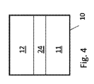
図3、図4及び図5は、本発明に係るシステム1による対象者のバイタルサイン情報の決定を図示している。図3は、光源21、検出ユニット22及びマーカーを示し、マーカーは、正面からは図4に、側面からは図5に詳細に示されており、第1のマーカーエリア11と第2のマーカーエリア12とを有している。マーカーは、検出ユニット22に、例えばレンズ13の正面に貼り付けられる。検出ユニットは、レンズと、図5に示される画像センサ14とを備える。組織は、血管105を備える。
Figures 3, 4 and 5 illustrate the determination of the vital sign information of the subject by the
この実施形態において、光源21は、少なくとも第1の波長λ1及び第2の波長λ2の光を放射する。第1のマーカーエリア11は、第1の波長の光を透過するように構成され、この第1の波長は、光源21の第1の波長に対応する。第2のマーカーエリア12は、第2の波長の光を透過するように構成され、この第2の波長は、光源21の第2の波長に対応する。図3は、第1の波長の光線Aと第2の波長の光線Dをスケッチしている。第1のマーカーエリア11は、第1の波長の光を透過するように構成されるので、光線Aは、対象者100の皮膚104に入り込む。光の一部は皮膚104内に吸収されるが、光の一部は、組織で反射されるか散乱されて、検出ユニットに到達する。吸収及び/又は反射特性は時間変化し、その血管105による組織104の時間変化するかん流を表す。
In this embodiment, the light source 21 emits at least a first wavelength lambda 1 and the second wavelength lambda 2 of light. The
検出ユニット22は、受信光学、例えば受信レンズ13と、画像センサ14を形成するフォト検出器又はピクセルのアレイ25とを備える。第1のマーカーエリア11から受け取った光は、第1のピクセル群又はピクセルアレイ26上に画像化される。これに対応して、第2のマーカーエリア12から受け取った光は、第2のピクセル群27上に画像化される。マーカーは更に、第3のマーカーエリア24を有してもよい。図4及び図5を参照されたい。第3のマーカーエリア24は、画像センサ14が感知する全ての波長をブロックするか減衰させる。ピクセルアレイ25は更に、第1及び第2のピクセル群を分離する第3のピクセル群23を備える。
The
組織内104の光の吸収は時間変化するので、検出ユニット22の画像センサに影響を与える光の強度も時間変化する。ピクセル26のエリアにおいて時間変化する強度は、曲線28によって示される。ピクセル群27に影響を与える時間変化する強度は、曲線29によって示される。
As the absorption of light in the tissue 104 changes with time, the intensity of light affecting the image sensor of the
第1のマーカーエリア11は、第1の波長の光のみを透過するように構成されるので、第2の波長の光は第1のマーカーエリア11を通過せず、第2のピクセル群又はピクセルアレイに画像化されない。同様に、第2のマーカーエリア12は、第2の波長の光のみを透過するように構成されるので、第1の波長の光は第2のマーカーエリア12を通過せず、第1のピクセル群又はピクセルアレイに画像化されない。それでもなお、マーカー10とレンズ13との間の距離に起因して、第1の波長の光の一部が第2のピクセル群27に到達する可能性があり、そして第2の波長の光の一部が第1のピクセル群26に到達する可能性があるので、結果として一部が混合することがある。そのような混合を防ぐために、第1のマーカーエリア11と第2のマーカーエリア12は、第1及び第2の波長をブロックする第3のマーカーエリア24によって相互から分離される。さらに、第1のピクセル群が、好ましくは、第3のピクセル群23によって第2のピクセル群から分離される。曲線28によって示される強度の変調は、第1の波長での組織104内の時間変化する反応に起因する。曲線29によって示される強度の変調は、第2の波長での組織104内の時間変化する反応に起因する。
Since the
対象者の心拍数を、曲線28又は曲線29の一方における時間変化する強度から直接決定することができる。しかしながら、フォトプレスチモグラフィにより血中酸素飽和度を決定するためには、以下で例示として説明されるように、少なくとも2つの波長が必要とされる。
The subject's heart rate can be determined directly from the time-varying intensity of one of
接触パルスオキシメータは、典型的に、赤(R)及び赤外(IR)(あるいはより正確には、多くの場合は赤外近くの)光を、関心対象の対象者の維管束組織を通して透過する。それぞれの光の部分(R/IR)を、交互に(高速切り替えにより)透過し、検出することができる。それぞれのスペクトル部分が、酸素化ヘモグロビン(HbO2)及び還元ヘモグロビン(Hb)によって別々に吸収されるとすると、血中酸素飽和度を等しく処理することができる。酸素飽和度(SO2)予測アルゴリズムは、赤色部分及び赤外部分に関連する信号比を使用することができる。さらに、このアルゴリズムは、非パルス(非拍動)信号コンポーネントを考慮することができる。典型的に、PPG信号は、図5に概略的に図示されるように、DCコンポーネントと、比較的小さな拍動のACコンポーネントとを備える。さらに、SO2予測は、一般に、処理された値に適用される、経験的に導出される較正係数を必要とする。典型的に、較正係数(又は較正曲線)は、侵襲的な血中酸素飽和度測定を要する基準測定に対して決定される。PPGデバイスは基本的に、血中酸素飽和度値へ転換されなければならない、(スペクトルの)信号部分の比を検出するので、較正係数が必要とされる。上記の比は、典型的にはHbO2とHbの比を含む。本発明を限定するようには意図されないが、例えば血中酸素飽和度予測は、以下の一般式に基づくことができる。 Contact pulse oximeters typically transmit red (R) and infrared (IR) (or more accurately, often near infrared) light through the vascular tissue of a subject of interest Do. Each portion of light (R / IR) can be alternately transmitted (with fast switching) and detected. Assuming that each spectral portion is absorbed separately by oxygenated hemoglobin (HbO 2 ) and reduced hemoglobin (Hb), blood oxygen saturation can be treated equally. An oxygen saturation (SO 2 ) prediction algorithm can use signal ratios associated with the red and infrared portions. Furthermore, the algorithm can consider non-pulsed (non-beating) signal components. Typically, the PPG signal comprises a DC component and a relatively small beating AC component, as schematically illustrated in FIG. Furthermore, SO 2 prediction is generally applied to the processed values, and requires a calibration factor that is empirically derived. Typically, a calibration factor (or calibration curve) is determined relative to a reference measurement that requires invasive blood oxygen saturation measurement. Since the PPG device basically detects the ratio of the (spectral) signal part that has to be converted to blood oxygen saturation value, a calibration factor is required. The above ratios typically include the ratio of HbO 2 to Hb. Although not intended to limit the present invention, for example, blood oxygen saturation prediction can be based on the following general formula:

一般的に、測定された強度曲線28、29は特徴信号として、かなりの程度一定の(considerably constant)(DC)部分と、このDC部分を重ね合せる交流(alternating)(AC)部分とを含むように考えられる。信号処理手段を適用して、AC部分を抽出し、更には外乱(disturbance)を補償することができる。例えば特徴信号のAC部分は、対象者100の血管の活動、特に心拍数を非常に良く示すことができる優位周波数を備えることができる。また、特徴信号、特にAC部分は、更なるバイタルパラメータを示すことができる。これに関連して、動脈血中酸素飽和度の検出は重要な利用分野である。上記のように、基本的に、動脈血中酸素飽和度を表す値は、別個のスペクトル部分における特徴信号のAC部分の挙動を考慮して計算され得る。言い換えると、動脈血中酸素飽和度の程度は、血管における異なる放射線吸収に反映され得る。さらに、酸素化の程度に起因する吸収における差異も、異なるスぺクトル部分にわたって著しく変わるという事実を使用することができる。さらに、信号のDC部分も血中酸素飽和度の検出に用いることができる。典型的に、DCコンポーネントは、組織、静脈血及び非拍動動脈血の全体的な光吸収を表す。対照的に、ACコンポーネントは、拍動動脈血の吸収を表し得る。したがって、動脈血中酸素飽和度(SaO2)の決定は、 Generally, the measured intensity curves 28 and 29 include, as feature signals, a fairly constant (DC) part and an alternating (AC) part that overlaps the DC part. It is thought. Signal processing means can be applied to extract the AC part and also to compensate for the disturbance. For example, the AC portion of the feature signal can comprise a dominant frequency that can very well indicate the activity of the subject's 100 blood vessels, in particular the heart rate. Also, the feature signal, in particular the AC part, can indicate additional vital parameters. In this context, detection of arterial blood oxygen saturation is an important application. As mentioned above, basically, values representing arterial blood oxygen saturation can be calculated taking into account the behavior of the AC part of the feature signal in separate spectral parts. In other words, the degree of arterial blood oxygen saturation may be reflected in the different radiation absorption in the blood vessels. Furthermore, it is possible to use the fact that differences in absorption due to the degree of oxygenation also vary significantly across different spectral moieties. Additionally, the DC portion of the signal can also be used to detect blood oxygen saturation. Typically, DC components represent the overall light absorption of tissue, venous blood and non-pulsatile arterial blood. In contrast, the AC component may represent pulsatile arterial blood absorption. Therefore, the determination of arterial blood oxygen saturation (SaO 2 )
式(2)及び式(3)は主として例示の目的で提示されていることを理解されたい。これらの式は、本開示の範囲を限定するものとして解釈されるべきではない。実際、当業者は、更に適切なSaO2導出モデルを決定及び確立し得る。検出される物質に応じて、代替的な波長の組合せ、例えば緑と赤の組合せを使用することができる。SaO2の測定について詳細に説明してきたが、これは、血液及び/又は組織内の物質の濃度を測定するという一般的な概念についての例として理解されよう。 It should be understood that equations (2) and (3) are presented primarily for illustrative purposes. These formulas should not be construed as limiting the scope of the present disclosure. In fact, one skilled in the art can determine and establish more appropriate SaO 2 derivation models. Depending on the substance to be detected, alternative wavelength combinations can be used, for example a combination of green and red. Although the measurement of SaO 2 has been described in detail, this may be understood as an example of the general concept of measuring the concentration of substances in blood and / or tissues.
マーカーは任意のジオメトリを有してよく、またマーカーエリアが異なる形状を有してもよい。図6は、本発明に従って対象者のバイタルサイン情報を決定するシステム1で使用するためのマーカーのより詳細な実施形態を示す。マーカー10は、各マーカーエリアが異なる波長で光を透過するように構成されるマーカーエリア11、12と、キャリア素子31によって形成される(画像センサによって検出可能な波長のための)不透明のマーカーエリア24を特徴としている。キャリア素子31は、その素子を有するマーカー10を担持し、機械的安定性を提供する。この実施形態において、キャリア素子31は更に、マーカー10を検出ユニットに取り付けるのを可能にする、ねじ山、クランプ、ストラップ又は接着剤といった取付け手段を備える。キャリア素子は、光を透過せず、マーカーエリア11、12の位置における開口又はウィンドウを特徴付ける部材から作成される。
The markers may have any geometry and the marker areas may have different shapes. FIG. 6 shows a more detailed embodiment of a marker for use in the
ウィンドウ11、12のそれぞれに、光学フィルタプレート56、57が配置され、ここで、フィルタプレート56は第1の波長の光を透過するように構成され、フィルタプレート57は第2の波長の光を透過するように構成される。例えば第1のマーカーエリア11は赤外光を透過するように構成され、第2のマーカーエリア12は赤色光を透過するように構成される。図6に示されるマーカー10の実施形態の第1及び第2のマーカーエリア11、12の光学ウィンドウは、予測される信号強度に応じて最適化される。例えば第1の要求波長、例えば緑の信号は、第2の要求波長、例えば赤の信号より強い。したがって、双方の波長において同様の信号強度を達成するよう、第2のマーカーエリア12の全体が第1のマーカーエリア11の全体に対して増大される。
An
図7は、上述のマーカー30が取り付けられたモバイルフォン又はスマートフォン101を備える、対象者のバイタルサイン情報を決定するためのシステムの更なる実施形態を示す。モバイルフォン101は、マーカーの第1のマーカーエリア及び第2のマーカーエリアから受け取った放射線を検出するための検出ユニット22を備える。検出ユニット22は、レンズと画像センサチップとを備える。モバイルフォンは更に、第1のマーカーエリア及び第2のマーカーエリアからの検出された放射線から対象者のバイタルサイン情報を決定するための分析ユニットを含む、プロセッサを備える。更なる実施形態では、対象者のバイタルサイン情報を決定するシステムは、眼鏡に含まれる。
FIG. 7 shows a further embodiment of a system for determining vital sign information of a subject comprising a mobile phone or
図8は、対象者のバイタルサイン情報を決定するための方法を図示しており、この方法は:
− 第1のフィルタエリア及び第2のフィルタエリアから受け取った放射線を検出するための検出ユニットに貼り付けられるマーカーのうち、第1の波長の光を透過するように構成される第1のマーカーエリアと、第2の波長の光を透過するように構成される第2のマーカーエリアとから受け取った放射線を検出する、第1のステップS1と;
− 第1のマーカーエリア及び第2のマーカーエリアからの検出された放射線から、対象者のバイタルサイン情報を決定する、第2のステップS2と;
を含む。本方法は、プログラムコードで実装されてよい。プログラムコードは、モバイルフォン101内に含まれるプロセッサにおいて実行されると、該プロセッサに、第1のマーカーエリア及び第2のマーカーエリアからの検出された放射線から、対象者のバイタルサイン情報を決定する分析ユニットの機能を実行させることになる。本方法の更なる実施形態では、第1のステップに先行して、ステップS0において、マーカーが検出ユニットに貼り付けられる。
FIG. 8 illustrates a method for determining vital sign information of a subject, the method comprising:
A first marker area of the markers affixed to the detection unit for detecting radiation received from the first filter area and the second filter area, the first marker area being arranged to transmit light of a first wavelength Detecting radiation received from a second marker area configured to transmit light of a second wavelength; and S1.
-Determining the vital sign information of the subject from the detected radiation from the first marker area and the second marker area, a second step S2;
including. The method may be implemented in program code. The program code, when executed on a processor included in the
例として、本発明を、例えば目立たないリモートの患者モニタリング、一般的な監視(general surveillance)、セキュリティモニタリング及びフィットネス装置のような、いわゆるライフスタイル環境等といった、ヘルスケアの分野に適用することができる。適用法には、酸素飽和度(パルスオキシメトリ)のモニタリング、心拍数、血圧、心拍出量、血液かん流の変化、自律機能の評価及び末梢血管疾患の検出が含まれる。 By way of example, the invention can be applied to the field of healthcare, for example so-called lifestyle environments such as unobtrusive remote patient monitoring, general surveillance, security monitoring and fitness equipment etc. . Methods of application include monitoring of oxygen saturation (pulse oximetry), heart rate, blood pressure, cardiac output, changes in blood perfusion, assessment of autonomic function and detection of peripheral vascular disease.
本発明を図面及び前述の説明において詳細に図示し、説明してきたが、このような図及び説明は、具体例又は例示として解釈されるべきであって制限的なものではなく、本発明は、開示される実施形態に限定されない。特許請求に係る発明を実施する際に、図面、本開示及び添付の請求項の教示から、開示される実施形態に対する他の変形が当業者により理解され、達成される可能性がある。 While the invention has been illustrated and described in detail in the drawings and foregoing description, such illustration and description are to be interpreted as illustrative or exemplary and not restrictive, and the present invention is not intended to be limited. It is not limited to the disclosed embodiments. Other variations to the disclosed embodiments can be understood and effected by those skilled in the art in practicing the claimed invention, from the teachings of the drawings, the disclosure and the appended claims.
特許請求の範囲において、「備える(comprising)」という用語は、他の要素又はステップを排除せず、不定冠詞「ある、1つの(a, an)」は複数を排除しない。単一の要素又は他のユニットが特許請求の範囲に記載される幾つかのアイテムの機能を満たすことがある。特定の手段が相互に異なる従属項に記載されているという単なる事実は、これらの手段の組合せを有意に用いることができないことを示すものではない。 In the claims, the term "comprising" does not exclude other elements or steps, and the indefinite article "a, an" does not exclude a plurality. A single element or other unit may fulfill the function of several items recited in the claims. The mere fact that certain measures are recited in mutually different dependent claims does not indicate that a combination of these measures can not be used to advantage.
コンピュータプログラムは、他のハードウェアとともに又は他のハードウェアの一部として光記憶媒体や半導体媒体のような、適切な非一時的媒体上に格納/分散させてよいが、インターネットや他の有線若しくは無線の電話通信システムといった他の形式で分散させてもよい。 The computer program may be stored / distributed on a suitable non-transitory medium, such as an optical storage medium or a semiconductor medium, as well as other hardware or as part of other hardware, but the Internet or other wired or wired It may be distributed in other forms such as a wireless telephone communication system.
特許請求項における参照符号は、範囲を限定するものとして解釈されるべきではない。 Any reference signs in the claims should not be construed as limiting the scope.
Claims (9)
レンズと画像センサとを備え、モバイルフォンに含まれるカメラと、
前記カメラへの取付けのためにキャリア素子によって担持されるマーカーであって、第1の波長の光を透過するように構成される第1マーカーエリアと、第2の波長の光を透過するように構成される第2マーカーエリアを含み、前記第1及び第2マーカーエリアはそれぞれ、第1及び第2光学フィルタプレートを備え、該第1及び第2光学フィルタプレートは前記キャリア素子に取り付けられる、マーカーと、
前記マーカーを担持し、前記カメラに取り付けられるキャリア素子であって、該キャリア素子は、前記第1マーカーエリアを通して透過される光が前記画像センサの第1の部分に当たり、前記第2マーカーエリアを通して透過される光が前記画像センサの第2の部分に当たるように前記カメラに取り付けられ、前記画像センサは少なくとも、前記画像センサの前記第1の部分から得られる第1色信号と、前記画像センサの前記第2の部分から得られる第2色信号とを生成する、キャリア素子と、
前記画像センサによって生成された前記第1及び第2色信号から、前記対象者の前記バイタルサイン情報を決定する、分析ユニットと、
を備える、システム。 A system for determining vital sign information of a subject:
A camera with a lens and an image sensor, included in a mobile phone,
A marker carried by the carrier element for attachment to the camera, the first marker area being configured to transmit light of a first wavelength, and to transmit light of a second wavelength A marker comprising a second marker area configured, the first and second marker areas respectively comprising a first and a second optical filter plate, the first and the second optical filter plate being attached to the carrier element, a marker When,
A carrier element carrying the marker and attached to the camera, wherein the light transmitted through the first marker area strikes a first portion of the image sensor and transmitted through the second marker area Light is applied to the camera such that a second portion of the image sensor strikes, the image sensor being at least a first color signal obtained from the first portion of the image sensor; A carrier element generating a second color signal obtained from the second part;
An analysis unit for determining the vital sign information of the subject from the first and second color signals generated by the image sensor;
A system comprising:
請求項1に記載のシステム。 The carrier element further comprises attachment means, preferably a screw thread or clamp, for attaching the carrier element to the camera.
The system of claim 1.
請求項1に記載のシステム。 The first and second marker areas are separated from one another by a third marker area configured to block light.
The system of claim 1.
第1の波長の光を透過するように構成され、第1光学フィルタプレートを備える第1マーカーエリアと、
第2の波長の光を透過するように構成され、第2光学フィルタプレートを備える第2マーカーエリアと、
を備え、当該マーカーはキャリア素子によって担持され、前記第1及び第2光学フィルタプレートが前記キャリア素子に取り付けられ、前記キャリア素子は、前記第1マーカーエリアを通して透過される光が前記カメラの画像センサの第1の部分に当たり、前記第2マーカーエリアを通して透過される光が前記画像センサの第2の部分に当たるように、前記カメラに取り付けられる、マーカー。 A marker for use in a system used with a mobile phone including a camera to determine vital sign information of a subject, comprising:
A first marker area configured to transmit light of a first wavelength and comprising a first optical filter plate;
A second marker area configured to transmit light of a second wavelength and comprising a second optical filter plate;
The marker is carried by the carrier element, the first and second optical filter plates are attached to the carrier element, and the carrier element is an image sensor of the camera for light transmitted through the first marker area A marker attached to the camera such that light transmitted through the second marker area strikes a second portion of the image sensor.
請求項4に記載のマーカー。 The first and second marker areas are separated from one another by a third marker area configured to block light.
A marker according to claim 4.
請求項4に記載のマーカー。 The carrier element further comprises a thread or clamp to allow attachment of the carrier element to a detection unit.
A marker according to claim 4.
レンズと画像センサとを備え、キャリア素子を介してマーカーが取り付けられるカメラであって、前記マーカーは、第1の波長の光を透過するように構成される第1マーカーエリアと、第2の波長の光を透過するように構成される第2マーカーエリアを有し、前記第1及び第2マーカーエリアはそれぞれ、第1及び第2光学フィルタプレートを備え、該第1及び第2光学フィルタプレートは前記キャリア素子に取り付けられ、前記キャリア素子は前記第1マーカーエリアを通して透過される光が前記画像センサの第1の部分に当たり、前記第2マーカーエリアを通して透過される光が前記画像センサの第2の部分に当たるように、前記カメラに取り付けられ、前記画像センサは、前記画像センサの前記第1の部分から得られる第1色信号と、前記画像センサの前記第2の部分から得られる第2色信号とを生成する、カメラと、
前記画像センサによって生成された前記第1及び第2色信号から、前記対象者の前記バイタルサイン情報を決定する、分析ユニットと、
を備える、デバイス。 A device for use in a system for determining vital sign information of a subject, comprising:
A camera comprising a lens and an image sensor, wherein a marker is attached via a carrier element, the marker comprising a first marker area configured to transmit light of a first wavelength, and a second wavelength A second marker area configured to transmit light of the first and second marker areas, the first and second marker areas respectively comprising first and second optical filter plates, the first and second optical filter plates comprising The carrier element is attached to the carrier element and the carrier element strikes a first portion of the image sensor as light transmitted through the first marker area and light as transmitted through the second marker area as a second of the image sensor Attached to the camera to hit a portion, and the image sensor is configured to receive a first color signal obtained from the first portion of the image sensor; It generates the second color signal obtained from the second portion of the serial image sensor, a camera,
An analysis unit for determining the vital sign information of the subject from the first and second color signals generated by the image sensor;
A device comprising:
請求項7に記載のデバイス。 The device comprises a mobile phone,
A device according to claim 7.
モバイルフォン内に含まれるカメラであって、キャリア素子を介してマーカーが取り付けられるカメラによって、前記マーカーのうち、第1の波長の光を透過するように構成される第1マーカーエリアと、第2の波長の光を透過するように構成される第2マーカーエリアとから受け取られる放射線を検出するステップであって、前記第1及び第2マーカーエリアはそれぞれ、第1及び第2光学フィルタプレートを備え、該第1及び第2光学フィルタプレートは前記キャリア素子に取り付けられ、前記カメラは、レンズと画像センサとを備え、前記キャリア素子は、前記第1マーカーエリアを通して透過される光が前記画像センサの第1の部分に当たり、前記第2マーカーエリアを通して透過される光が前記画像センサの第2の部分に当たるように、前記カメラに取り付けられるステップと、
前記画像センサによって、前記画像センサの前記第1の部分から得られる第1色信号と、前記画像センサの前記第2の部分から得られる第2色信号とを生成するステップと、
前記画像センサによって生成された前記第1及び第2色信号から、前記対象者の前記バイタルサイン情報を決定するステップと、
を備える、方法。 In a method of determining vital sign information of a subject,
A camera included in the mobile phone, a first marker area of the markers configured to transmit light of a first wavelength by the camera to which the marker is attached via the carrier element; Detecting radiation received from a second marker area configured to transmit light of a second wavelength, the first and second marker areas respectively comprising first and second optical filter plates The first and second optical filter plates are attached to the carrier element, the camera comprises a lens and an image sensor, and the carrier element is configured to receive light transmitted through the first marker area of the image sensor. The first part is hit, and the light transmitted through the second marker area hits the second part of the image sensor. In a step attached to the camera,
Generating, by the image sensor, a first color signal obtained from the first portion of the image sensor and a second color signal obtained from the second portion of the image sensor;
Determining the vital sign information of the subject from the first and second color signals generated by the image sensor;
A method comprising.
Applications Claiming Priority (5)
| Application Number | Priority Date | Filing Date | Title |
|---|---|---|---|
| US201361760683P | 2013-02-05 | 2013-02-05 | |
| EP13154017.1A EP2762066A1 (en) | 2013-02-05 | 2013-02-05 | System and method for determining vital sign information of a subject |
| EP13154017.1 | 2013-02-05 | ||
| US61/760,683 | 2013-02-05 | ||
| PCT/IB2014/058781 WO2014122577A1 (en) | 2013-02-05 | 2014-02-04 | System and method for determining vital sign information of a subject |
Publications (2)
| Publication Number | Publication Date |
|---|---|
| JP2016511659A JP2016511659A (en) | 2016-04-21 |
| JP6525890B2 true JP6525890B2 (en) | 2019-06-05 |
Family
ID=47630213
Family Applications (2)
| Application Number | Title | Priority Date | Filing Date |
|---|---|---|---|
| JP2015555747A Expired - Fee Related JP6388604B2 (en) | 2013-02-05 | 2014-02-04 | System and method for determining vital sign information of a subject |
| JP2015555844A Expired - Fee Related JP6525890B2 (en) | 2013-02-05 | 2014-02-04 | System and method for determining vital sign information of a subject |
Family Applications Before (1)
| Application Number | Title | Priority Date | Filing Date |
|---|---|---|---|
| JP2015555747A Expired - Fee Related JP6388604B2 (en) | 2013-02-05 | 2014-02-04 | System and method for determining vital sign information of a subject |
Country Status (10)
| Country | Link |
|---|---|
| US (2) | US10660524B2 (en) |
| EP (3) | EP2762066A1 (en) |
| JP (2) | JP6388604B2 (en) |
| CN (2) | CN104981200B (en) |
| BR (1) | BR112015018351A2 (en) |
| CA (1) | CA2899988A1 (en) |
| MX (1) | MX2015009946A (en) |
| RU (1) | RU2688445C2 (en) |
| WO (2) | WO2014122577A1 (en) |
| ZA (1) | ZA201506510B (en) |
Families Citing this family (29)
| Publication number | Priority date | Publication date | Assignee | Title |
|---|---|---|---|---|
| WO2013186696A1 (en) | 2012-06-12 | 2013-12-19 | Koninklijke Philips N.V. | System for camera-based vital sign measurement |
| WO2015062969A1 (en) | 2013-11-01 | 2015-05-07 | Koninklijke Philips N.V. | System and method for determining vital sign information of a subject |
| CN105266759A (en) * | 2014-05-26 | 2016-01-27 | 义明科技股份有限公司 | Physiological signal detection device |
| WO2016057633A1 (en) | 2014-10-08 | 2016-04-14 | Revealix, Inc. | Automated systems and methods for skin assessment and early detection of a latent pathogenic bio-signal anomaly |
| US10242278B2 (en) | 2014-12-01 | 2019-03-26 | Koninklijke Philips N.V. | Device and method for skin detection |
| WO2016111696A1 (en) * | 2015-01-09 | 2016-07-14 | Lifeq Global Limited | A ppg-based physiological sensing system with a spatio-temporal sampling approach towards identifying and removing motion artifacts from optical signals |
| CN112932416A (en) | 2015-06-04 | 2021-06-11 | 松下知识产权经营株式会社 | Biological information detection device and biological information detection method |
| US11154203B2 (en) | 2015-06-14 | 2021-10-26 | Facense Ltd. | Detecting fever from images and temperatures |
| US11103139B2 (en) | 2015-06-14 | 2021-08-31 | Facense Ltd. | Detecting fever from video images and a baseline |
| JP6625219B2 (en) * | 2015-12-21 | 2019-12-25 | コーニンクレッカ フィリップス エヌ ヴェKoninklijke Philips N.V. | Device, method and computer program product for continuous monitoring of vital signs |
| WO2017139895A1 (en) * | 2016-02-17 | 2017-08-24 | Nuralogix Corporation | System and method for detecting physiological state |
| WO2017152098A1 (en) * | 2016-03-03 | 2017-09-08 | Board Of Trustees Of Michigan State University | Method and apparatus for cuff-less blood pressure measurement |
| US10398324B2 (en) | 2016-03-03 | 2019-09-03 | Board Of Trustees Of Michigan State University | Method and apparatus for cuff-less blood pressure measurement in a mobile device |
| JP2017176267A (en) * | 2016-03-28 | 2017-10-05 | 富士ゼロックス株式会社 | Biological information measurement device and light-emitting device |
| US10335045B2 (en) | 2016-06-24 | 2019-07-02 | Universita Degli Studi Di Trento | Self-adaptive matrix completion for heart rate estimation from face videos under realistic conditions |
| US20190175030A1 (en) * | 2016-08-09 | 2019-06-13 | Koninklijke Philips N.V. | Device, system and method for monitoring of peripheral arterial perfusion of a subject |
| WO2018047040A1 (en) * | 2016-09-08 | 2018-03-15 | Presens Precision Sensing Gmbh | Method for calibrated optical measurement and system therefor |
| CN108125673B (en) * | 2016-12-01 | 2023-03-14 | 松下知识产权经营株式会社 | Biological information detection device |
| CN111433589B (en) * | 2017-09-21 | 2023-02-24 | 维塔生物科技公司 | Imaging method and system and computer readable medium |
| CN117731393A (en) * | 2017-09-22 | 2024-03-22 | 直观外科手术操作公司 | Enhancing visible differences between different tissues in computer-assisted teleoperated surgery |
| US11471083B2 (en) | 2017-10-24 | 2022-10-18 | Nuralogix Corporation | System and method for camera-based stress determination |
| US10646145B2 (en) * | 2018-02-09 | 2020-05-12 | General Electric Company | Reflective SpO2 measurement system and method |
| CN108852307B (en) * | 2018-05-24 | 2020-11-24 | 重庆理工大学 | Non-contact non-invasive arteriosclerosis detection device |
| CN112770668A (en) | 2018-07-16 | 2021-05-07 | 布鲁恩医疗创新有限责任公司 | Perfusion and oxygenation measurements |
| EP3613337A1 (en) * | 2018-08-22 | 2020-02-26 | Nokia Technologies Oy | An apparatus, method and computer program for determining a biometric parameter |
| US11681886B2 (en) * | 2018-09-06 | 2023-06-20 | John P. Peeters | Genomic and environmental blockchain sensors |
| US11779222B2 (en) * | 2019-07-10 | 2023-10-10 | Compal Electronics, Inc. | Method of and imaging system for clinical sign detection |
| CN112617746B (en) * | 2019-10-09 | 2024-04-09 | 钜怡智慧股份有限公司 | Non-contact physiological signal detection device |
| TWI772689B (en) * | 2019-10-09 | 2022-08-01 | 鉅怡智慧股份有限公司 | Non-contact physiological signal measuring device |
Family Cites Families (45)
| Publication number | Priority date | Publication date | Assignee | Title |
|---|---|---|---|---|
| US5441048A (en) * | 1988-09-08 | 1995-08-15 | Sudor Partners | Method and apparatus for determination of chemical species in perspiration |
| GB9011887D0 (en) * | 1990-05-26 | 1990-07-18 | Le Fit Ltd | Pulse responsive device |
| US5267563A (en) * | 1991-06-28 | 1993-12-07 | Nellcor Incorporated | Oximeter sensor with perfusion enhancing |
| US5544649A (en) | 1992-03-25 | 1996-08-13 | Cardiomedix, Inc. | Ambulatory patient health monitoring techniques utilizing interactive visual communication |
| JPH06285048A (en) | 1993-03-19 | 1994-10-11 | Nellcor Inc | Oxygen analyzer with perfusion enhancing means |
| JP3547968B2 (en) * | 1998-01-19 | 2004-07-28 | 株式会社日本自動車部品総合研究所 | Pulse waveform detector |
| US6352517B1 (en) | 1998-06-02 | 2002-03-05 | Stephen Thomas Flock | Optical monitor of anatomical movement and uses thereof |
| US6980679B2 (en) * | 1998-10-23 | 2005-12-27 | Varian Medical System Technologies, Inc. | Method and system for monitoring breathing activity of a subject |
| US20050027182A1 (en) | 2001-12-27 | 2005-02-03 | Uzair Siddiqui | System for monitoring physiological characteristics |
| JP2004187980A (en) | 2002-12-12 | 2004-07-08 | Fuji Photo Film Co Ltd | Medical image processor and medical image processing method |
| EP1670356A1 (en) * | 2003-09-03 | 2006-06-21 | Life Patch International, Inc. | Personal diagnostic devices and related methods |
| CN101366632A (en) * | 2004-08-03 | 2009-02-18 | 武汉一海数字工程有限公司 | Mammary tissue blood oxygen function imaging system |
| DE102005036410A1 (en) * | 2005-07-29 | 2007-02-01 | Biocam Gmbh | Method for determining the oxygen partial pressure distribution in at least one tissue surface section, in particular skin tissue surface section |
| US7499739B2 (en) * | 2005-10-27 | 2009-03-03 | Smiths Medical Pm, Inc. | Single use pulse oximeter |
| US20070142715A1 (en) * | 2005-12-20 | 2007-06-21 | Triage Wireless, Inc. | Chest strap for measuring vital signs |
| AU2007272297A1 (en) * | 2006-07-11 | 2008-01-17 | Paul Nigel Brockwell | Indicator system for determining analyte concentration |
| US20100056887A1 (en) * | 2006-11-27 | 2010-03-04 | Pioneer Corporation | Emission sensor device and bioinformation detecting method |
| US7434724B2 (en) * | 2006-12-22 | 2008-10-14 | Welch Allyn, Inc. | Dynamic barcode for displaying medical data |
| JP2008167853A (en) | 2007-01-10 | 2008-07-24 | Fujifilm Corp | Test sheet, object diagnostic apparatus and method, and program |
| US20080317628A1 (en) * | 2007-06-19 | 2008-12-25 | Fujifilm Corporation | Check sheet |
| JP5061353B2 (en) | 2007-06-19 | 2012-10-31 | 富士フイルム株式会社 | Inspection sheet |
| US8106344B2 (en) | 2008-02-18 | 2012-01-31 | Panasonic Corporation | Compound eye camera module |
| US20090226071A1 (en) * | 2008-03-06 | 2009-09-10 | Motorola, Inc. | Method and Apparatus to Facilitate Using Visible Light Images to Determine a Heart Rate |
| US8384916B2 (en) * | 2008-07-24 | 2013-02-26 | Massachusetts Institute Of Technology | Dynamic three-dimensional imaging of ear canals |
| US10729357B2 (en) | 2010-04-22 | 2020-08-04 | Leaf Healthcare, Inc. | Systems and methods for generating and/or adjusting a repositioning schedule for a person |
| US20100268094A1 (en) * | 2009-04-15 | 2010-10-21 | Oceanit Laboratories Inc. | Consumer electronic camera photoplethysmograph |
| WO2011007271A1 (en) | 2009-07-15 | 2011-01-20 | Koninklijke Philips Electronics N.V. | Method for automatic setting time varying parameter alert and alarm limits |
| US8670812B2 (en) * | 2009-07-23 | 2014-03-11 | Covidien Lp | Physiological sensor having a waist |
| FR2949658B1 (en) * | 2009-09-07 | 2012-07-27 | Salim Mimouni | OPTICAL PLETHYSMOGRAPHIC SIGNAL CAPTURE DEVICE USING MATRIX IMAGER |
| WO2011042851A1 (en) * | 2009-10-06 | 2011-04-14 | Koninklijke Philips Electronics N.V. | Method and system for carrying out photoplethysmography |
| US8666116B2 (en) * | 2009-10-06 | 2014-03-04 | Koninklijke Philips N.V. | Method and system for obtaining a first signal for analysis to characterize at least one periodic component thereof |
| JP2011147469A (en) | 2010-01-19 | 2011-08-04 | Rohm Co Ltd | Biological information acquisition device |
| JP5446915B2 (en) * | 2010-01-21 | 2014-03-19 | セイコーエプソン株式会社 | Biological information detector and biological information measuring device |
| US8602988B2 (en) * | 2010-02-02 | 2013-12-10 | Recovery Science and Technology, LLC | Recovery determination methods and recovery determination apparatuses |
| EP2544583B1 (en) * | 2010-03-08 | 2016-03-02 | Bruce Adams | System, method and article for normalization and enhancement of tissue images |
| US8761853B2 (en) * | 2011-01-20 | 2014-06-24 | Nitto Denko Corporation | Devices and methods for non-invasive optical physiological measurements |
| CA2825331A1 (en) * | 2011-01-21 | 2012-07-26 | Worcester Polytechnic Institute | Physiological parameter monitoring with a mobile communication device |
| US8718748B2 (en) | 2011-03-29 | 2014-05-06 | Kaliber Imaging Inc. | System and methods for monitoring and assessing mobility |
| DE102011017064A1 (en) * | 2011-04-14 | 2012-10-18 | Ingo Flore | Diagnostic measuring device with integrated spectrometer |
| CN103476330B (en) * | 2011-04-21 | 2016-07-13 | 皇家飞利浦有限公司 | The equipment of life sign measurement and method for people |
| US10521900B2 (en) | 2011-09-02 | 2019-12-31 | Koninklijke Philips N.V. | Camera for generating a biometrical signal of a living being |
| US20130267854A1 (en) * | 2012-04-09 | 2013-10-10 | Jami Johnson | Optical Monitoring and Computing Devices and Methods of Use |
| US20130303921A1 (en) * | 2012-05-11 | 2013-11-14 | Hong Kong Applied Science and Technology Research Institute Company Limited | System and Method for Measurement of Physiological Data with Light Modulation |
| WO2013186696A1 (en) * | 2012-06-12 | 2013-12-19 | Koninklijke Philips N.V. | System for camera-based vital sign measurement |
| CN107003560B (en) | 2014-11-28 | 2020-07-07 | 堺显示器制品株式会社 | Backlight device and liquid crystal display device |
-
2013
- 2013-02-05 EP EP13154017.1A patent/EP2762066A1/en not_active Withdrawn
-
2014
- 2014-01-28 US US14/165,642 patent/US10660524B2/en active Active
- 2014-02-04 JP JP2015555747A patent/JP6388604B2/en not_active Expired - Fee Related
- 2014-02-04 BR BR112015018351A patent/BR112015018351A2/en not_active IP Right Cessation
- 2014-02-04 WO PCT/IB2014/058781 patent/WO2014122577A1/en active Application Filing
- 2014-02-04 JP JP2015555844A patent/JP6525890B2/en not_active Expired - Fee Related
- 2014-02-04 EP EP14704928.2A patent/EP2953530A1/en not_active Withdrawn
- 2014-02-04 MX MX2015009946A patent/MX2015009946A/en unknown
- 2014-02-04 WO PCT/EP2014/052143 patent/WO2014122126A1/en active Application Filing
- 2014-02-04 EP EP14702292.5A patent/EP2953529A1/en not_active Withdrawn
- 2014-02-04 CN CN201480007177.2A patent/CN104981200B/en not_active Expired - Fee Related
- 2014-02-04 US US14/764,588 patent/US9980650B2/en not_active Expired - Fee Related
- 2014-02-04 CN CN201480007187.6A patent/CN104968259B/en not_active Expired - Fee Related
- 2014-02-04 CA CA2899988A patent/CA2899988A1/en not_active Abandoned
- 2014-02-04 RU RU2015137775A patent/RU2688445C2/en not_active IP Right Cessation
-
2015
- 2015-09-04 ZA ZA2015/06510A patent/ZA201506510B/en unknown
Also Published As
| Publication number | Publication date |
|---|---|
| EP2953530A1 (en) | 2015-12-16 |
| EP2762066A1 (en) | 2014-08-06 |
| WO2014122126A1 (en) | 2014-08-14 |
| US10660524B2 (en) | 2020-05-26 |
| RU2015137775A (en) | 2017-03-13 |
| US20150366455A1 (en) | 2015-12-24 |
| MX2015009946A (en) | 2015-09-29 |
| US9980650B2 (en) | 2018-05-29 |
| WO2014122577A1 (en) | 2014-08-14 |
| CN104981200B (en) | 2018-10-16 |
| ZA201506510B (en) | 2017-08-30 |
| RU2688445C2 (en) | 2019-05-21 |
| CA2899988A1 (en) | 2014-08-14 |
| CN104968259A (en) | 2015-10-07 |
| JP2016508777A (en) | 2016-03-24 |
| EP2953529A1 (en) | 2015-12-16 |
| US20140221847A1 (en) | 2014-08-07 |
| BR112015018351A2 (en) | 2017-07-18 |
| JP2016511659A (en) | 2016-04-21 |
| JP6388604B2 (en) | 2018-09-12 |
| CN104981200A (en) | 2015-10-14 |
| CN104968259B (en) | 2018-07-13 |
Similar Documents
| Publication | Publication Date | Title |
|---|---|---|
| JP6525890B2 (en) | System and method for determining vital sign information of a subject | |
| US9999355B2 (en) | Device, system and method for determining vital signs of a subject based on reflected and transmitted light | |
| JP6654700B2 (en) | Apparatus, system, and operation method for determining vital sign information of a subject | |
| US11147456B2 (en) | Marker with light emitting area for use in determining vital sign information | |
| US20190200871A1 (en) | System and method for vital signs detection | |
| EP3104767B1 (en) | Device, system and method for determining vital signs of a subject based on reflected and transmitted light | |
| JP7304899B2 (en) | Systems and methods for determining at least one vital sign of a subject | |
| US11712185B2 (en) | Device, system and method for extracting physiological information indicative of at least one vital sign of a subject | |
| US20220047221A1 (en) | System and method for determining at least one vital sign of a subject | |
| JP7399112B2 (en) | Systems and methods for determining at least one vital sign of a subject | |
| JP6682605B2 (en) | Device and method for determining a vital sign of an object based on reflected and transmitted light |
Legal Events
| Date | Code | Title | Description |
|---|---|---|---|
| A621 | Written request for application examination |
Free format text: JAPANESE INTERMEDIATE CODE: A621 Effective date: 20170201 |
|
| A977 | Report on retrieval |
Free format text: JAPANESE INTERMEDIATE CODE: A971007 Effective date: 20171115 |
|
| A131 | Notification of reasons for refusal |
Free format text: JAPANESE INTERMEDIATE CODE: A131 Effective date: 20180109 |
|
| A521 | Request for written amendment filed |
Free format text: JAPANESE INTERMEDIATE CODE: A523 Effective date: 20180403 |
|
| A02 | Decision of refusal |
Free format text: JAPANESE INTERMEDIATE CODE: A02 Effective date: 20180911 |
|
| A521 | Request for written amendment filed |
Free format text: JAPANESE INTERMEDIATE CODE: A523 Effective date: 20190108 |
|
| A911 | Transfer to examiner for re-examination before appeal (zenchi) |
Free format text: JAPANESE INTERMEDIATE CODE: A911 Effective date: 20190117 |
|
| TRDD | Decision of grant or rejection written | ||
| A01 | Written decision to grant a patent or to grant a registration (utility model) |
Free format text: JAPANESE INTERMEDIATE CODE: A01 Effective date: 20190409 |
|
| A61 | First payment of annual fees (during grant procedure) |
Free format text: JAPANESE INTERMEDIATE CODE: A61 Effective date: 20190507 |
|
| R150 | Certificate of patent or registration of utility model |
Ref document number: 6525890 Country of ref document: JP Free format text: JAPANESE INTERMEDIATE CODE: R150 |
|
| LAPS | Cancellation because of no payment of annual fees |