JP6525233B2 - 2-axis hinge and terminal device using the 2-axis hinge - Google Patents

2-axis hinge and terminal device using the 2-axis hinge Download PDF

Info

Publication number
JP6525233B2
JP6525233B2 JP2013247542A JP2013247542A JP6525233B2 JP 6525233 B2 JP6525233 B2 JP 6525233B2 JP 2013247542 A JP2013247542 A JP 2013247542A JP 2013247542 A JP2013247542 A JP 2013247542A JP 6525233 B2 JP6525233 B2 JP 6525233B2
Authority
JP
Japan
Prior art keywords
hinge shaft
housing
hinge
cam
stopper
Prior art date
Legal status (The legal status is an assumption and is not a legal conclusion. Google has not performed a legal analysis and makes no representation as to the accuracy of the status listed.)
Active
Application number
JP2013247542A
Other languages
Japanese (ja)
Other versions
JP2015105693A (en
JP2015105693A5 (en
Inventor
英樹 本杉
英樹 本杉
Current Assignee (The listed assignees may be inaccurate. Google has not performed a legal analysis and makes no representation or warranty as to the accuracy of the list.)
Naturaleza One Co Ltd
Original Assignee
Naturaleza One Co Ltd
Priority date (The priority date is an assumption and is not a legal conclusion. Google has not performed a legal analysis and makes no representation as to the accuracy of the date listed.)
Filing date
Publication date
Application filed by Naturaleza One Co Ltd filed Critical Naturaleza One Co Ltd
Priority to JP2013247542A priority Critical patent/JP6525233B2/en
Priority to CN201410710296.6A priority patent/CN104675845B/en
Priority to TW103141471A priority patent/TW201521556A/en
Publication of JP2015105693A publication Critical patent/JP2015105693A/en
Publication of JP2015105693A5 publication Critical patent/JP2015105693A5/ja
Application granted granted Critical
Publication of JP6525233B2 publication Critical patent/JP6525233B2/en
Active legal-status Critical Current
Anticipated expiration legal-status Critical

Links

Images

Classifications

    • GPHYSICS
    • G06COMPUTING; CALCULATING OR COUNTING
    • G06FELECTRIC DIGITAL DATA PROCESSING
    • G06F1/00Details not covered by groups G06F3/00 - G06F13/00 and G06F21/00
    • G06F1/16Constructional details or arrangements
    • G06F1/1613Constructional details or arrangements for portable computers
    • G06F1/1633Constructional details or arrangements of portable computers not specific to the type of enclosures covered by groups G06F1/1615 - G06F1/1626
    • G06F1/1675Miscellaneous details related to the relative movement between the different enclosures or enclosure parts
    • G06F1/1681Details related solely to hinges

Landscapes

  • Engineering & Computer Science (AREA)
  • Computer Hardware Design (AREA)
  • Theoretical Computer Science (AREA)
  • Human Computer Interaction (AREA)
  • Physics & Mathematics (AREA)
  • General Engineering & Computer Science (AREA)
  • General Physics & Mathematics (AREA)
  • Telephone Set Structure (AREA)
  • Pivots And Pivotal Connections (AREA)

Description

本発明は、ノートパソコンやモバイルパソコン、PDAなどの端末機器に用いて好適な2軸ヒンジに関する。   The present invention relates to a two-axis hinge suitable for use in terminal devices such as notebook computers, mobile computers, and PDAs.

キーボード部を設けた第1筐体とディスプレイ部を設けた第2筐体を有する、ノートパソコンやモバイルパソコン、PDAなどの端末機器においては、第1筐体と第2筐体を上下方向へ開閉可能に連結する1軸からなる1軸ヒンジと、第1筐体と第2筐体を上下方向へ90度開いた後、水平方向へ第2筐体を第1筐体に対して回転できるようにするための2軸から成る2軸ヒンジとがある。本発明はこの2軸ヒンジに関する。   In a terminal device such as a notebook computer, a mobile personal computer, or a PDA having a first housing provided with a keyboard unit and a second housing provided with a display unit, the first housing and the second housing are opened and closed vertically. In order to be able to rotate the second housing in the horizontal direction with respect to the first housing after opening the first housing and the second housing 90 degrees in the vertical direction, and the uniaxial hinge consisting of one axis which enables the connection. And a two-axis two-axis hinge. The present invention relates to this biaxial hinge.

従来、このような構成の2軸ヒンジとして、下記特許文献1に記載されたものが公知である。この特許文献1に記載の2軸ヒンジは、第1の部材(第1筐体)に取り付けたシャフトと、第2の部材(第2筐体)に取り付けたシャフトを、連結アームで連結すると共に各シャフトにフリクショントルク発生手段を設け、さらにリンクアームを設けたものであるが、第1の部材と第2の部材を180度以上開くことができるようには構成されていず、また第1の部材と第2の部材を規則性を持って開閉できるようには構成されていない。   Conventionally, as a biaxial hinge of such a configuration, one described in Patent Document 1 below is known. The two-axis hinge described in Patent Document 1 connects a shaft attached to a first member (first housing) and a shaft attached to a second member (second housing) by a connecting arm. Although a friction torque generating means is provided on each shaft and a link arm is further provided, the first member and the second member are not configured to be opened 180 degrees or more, and the first It is not configured to be able to open and close the member and the second member with regularity.

特開2009−063039号公報JP, 2009-063039, A

近年、ノートパソコンなどの端末機器に求められるニーズは多様化し、それ合わせて端末機器の持つ機能も多様化している。そんな中で、例えばノートパソコンとして使用できる以外に同時にタブレットとしても用いることのできるようにするために、端末機器を構成する第1筐体と第2筐体をヒンジを介して0度の閉成状態から360度まで一方の筐体の開閉操作時には他方の筐体の開閉操作を規制できるように、また、開閉操作の順番を第1筐体か第2筐体のいずれか一方に規制できるように、所定の規則性を持って開閉することができるように成したヒンジが求められている。 In recent years, needs to be sought to the terminal device such as a laptop and diversification, it is also diversified functions of the terminal equipment accordingly. In such a case, for example, in order to be able to be used as a tablet at the same time as being usable as a notebook computer, the first case and the second case constituting the terminal device are closed at 0 degrees via a hinge. In order to be able to regulate the opening and closing operation of the other casing from the state to 360 degrees from the state, and to restrict the order of the opening and closing manipulation to either the first casing or the second casing There is a need for a hinge that can be opened and closed with a predetermined regularity.

そこで、本願出願人は、先の特許出願(特願2012−123093)で、第1筐体と第2筐体を上下方向へ180度ずつ合計で360度開くことができるように構成した2軸ヒンジを提案した。この発明はこれはこれで有用性を持っていることに違いはないが、その後、さらに小刻みに開閉角度調節をすることができるように成したものが求められることになった。   Therefore, in the previous patent application (Japanese Patent Application No. 2012-123093), the applicant of the present invention is configured such that the first housing and the second housing can be opened 360 degrees in total by 180 degrees in the vertical direction. I proposed a hinge. Although the present invention has no difference in its usefulness at this time, it has subsequently been sought to be able to adjust the opening and closing angle more gradually.

そこで本発明の目的は、とくにノートパソコンのような端末機器の第1筐体と第2筐体を0度から360度にわたって交互に規則性を持って小刻みに開閉でき、任意の開閉角度で安定停止状態で保持できる2軸ヒンジを提供せんとするにある。   Therefore, the object of the present invention is to open and close the first housing and the second housing of a terminal device such as a notebook personal computer with regularity alternately from 0 degrees to 360 degrees, and stabilize at any opening angle. An object of the present invention is to provide a two-axis hinge that can be held in a stopped state.

上記した目的を達成するために請求項1に記載の2軸ヒンジは、第1筐体と第2筐体を相対的に開閉させる2軸ヒンジであって、前記第1筐体側へ取り付けられる第1ヒンジシャフトと、前記第2筐体側へ取り付けられる第2ヒンジシャフトとを少なくとも第1連結部材と第2連結部材で平行状態に連結して互いに回転可能に設け、前記第1ヒンジシャフトと前記第2ヒンジシャフトとの間に当該第1ヒンジシャフトと当該第2ヒンジシャフトを選択的に回転させる第1選択的回転規制手段と第2選択的回転規制手段を設け、前記第1選択的回転規制手段を、前記第2連結部材と前記第1ヒンジシャフト及び前記第2ヒンジシャフトを回転可能に挿通させたスライドガイド部材との間に、上下方向へスライド可能に設けたところの下部と上部に第1カム凸部と第2カム凸部を有するロック部材と、このロック部材を挟んで前記第1ヒンジシャフトと前記第2ヒンジシャフトをそれぞれ挿通係合させ互いにそれぞれ第1Aカム凹部及び第1Bカム凹部と第2Aカム凹部及び第2Bカム凹部を有する第1Aロックカム部材及び第1Bロックカム部材とを有するものとし、前記第2選択的回転規制手段を、前記第1ヒンジシャフト及び前記第2ヒンジシャフトにそれぞれ回転を拘束されて取り付けられた第2Aロックカム部材及び第2Bロックカム部材と、これらの第2Aロックカム部材及び第2Bロックカム部材の間に回転可能に設けられ、その回転角度によって前記第2Aロックカム部材及び第2Bロックカム部材と係合する移動ストッパーと、前記第1ヒンジシャフトと第2ヒンジシャフトに回転可能に取り付けられ前記移動ストッパーと係合させられると共に、第1A弾性手段と第1B弾性手段によって前記第2Aロックカム部材と前記第2Bロックカム部材に圧接させられる第1ストッパーレバー及び第2ストッパーレバーとを有するものとすることにより、前記第1選択的回転規制手段と前記第2選択的回転規制手段により、前記第1筐体と前記第2筐体を交互に順序だって開閉することができるように成して、閉成状態の0度から全開成状態の360度までの間を開閉できるように成した構成を有することを特徴とする。 In order to achieve the above-mentioned object, a biaxial hinge according to claim 1 is a biaxial hinge for opening and closing a first housing and a second housing relative to each other, and is attached to the first housing side. A first hinge shaft and a second hinge shaft attached to the second housing side are connected in parallel by at least a first connection member and a second connection member, and are rotatably provided to each other; the first selective rotation restricting means and the second selective rotation restricting means for selectively rotating the first hinge shaft and the second hinge shaft between the second hinge shaft is provided, the first selective rotation restricting means A lower portion and an upper portion provided slidably in the vertical direction between the second connection member and a slide guide member rotatably inserting the first hinge shaft and the second hinge shaft A lock member having a first cam convex portion and a second cam convex portion, and the first hinge shaft and the second hinge shaft are respectively inserted and engaged with the lock member interposed therebetween, and the first A cam concave portion and the first B cam respectively. It has a first A lock cam member and a first B lock cam member having a recess, a second A cam recess and a second B cam recess, and the second selective rotation restricting means comprises the first hinge shaft and the second hinge shaft. It is rotatably provided between the second A lock cam member and the second B lock cam member mounted with their rotation restricted, and the second A lock cam member and the second B lock cam member, and the second A lock cam member and the second A lock cam member A movable stopper engaged with the second B lock cam member, the first hinge shaft and the second hinge A first stopper lever and a second stopper which are rotatably attached to the shaft and engaged with the movable stopper, and are brought into pressure contact with the second A lock cam member and the second B lock cam member by the first A elastic means and the first B elastic means. by as having a lever, by the first selective rotation restricting means and said second selective rotation restricting means, the first housing and the second housing can be opened and closed alternately Datte order Thus, it is characterized in that it is configured to be able to open and close between 0 degree in the closed state and 360 degrees in the fully open state.

また、請求項2に記載の2軸ヒンジは、前記第1選択的回転規制手段及び前記第2選択的回転規制手段に加えて前記第1ヒンジシャフト及び前記第2ヒンジシャフトにそれぞれフリクショントルク発生手段を設け、この各フリクショントルク発生手段により、前記第1筐体と前記第2筐体の開閉操作時にフリクショントルクを発生させることを特徴とする。 According to a second aspect of the present invention, in addition to the first selective rotation restricting means and the second selective rotation restricting means, friction torque generating means are respectively provided to the first hinge shaft and the second hinge shaft. The friction torque is generated at the time of the opening and closing operation of the first housing and the second housing by the friction torque generating means.

また、請求項3に記載の2軸ヒンジは、前記第1選択的回転規制手段と前記第2選択的回転規制手段に加えて前記第1ヒンジシャフト及び前記第2ヒンジシャフトにそれぞれ吸い込み手段を設け、この各吸い込み手段により、前記第1筐体と前記第2筐体の閉成状態の0度から全開成状態の360度までの間の所定の開閉角度から前記第1筐体と前記第2筐体を自動的に開閉できるように成した構成を有することを特徴とする。 According to a third aspect of the invention, the first hinge shaft and the second hinge shaft are provided with suction means in addition to the first selective rotation restricting means and the second selective rotation restricting means. The respective suction means make the first housing and the second housing open from a predetermined opening angle between 0 degrees in the closed state of the first housing and the second housing to 360 degrees in the fully open state. It is characterized in that it has a configuration capable of automatically opening and closing the case.

その際に、請求項4に係る2軸ヒンジは、前記第1選択的回転規制手段と前記第2選択的回転規制手段に加えて前記第1ヒンジシャフト及び前記第2ヒンジシャフトにそれぞれストッパー手段を設け、この各ストッパー手段により、前記第1筐体と前記第2筐体の相対的開閉角度を所定の開成角度に規制することを特徴とする。 At that time, in addition to the first selective rotation restricting means and the second selective rotation restricting means, the biaxial hinge according to a fourth aspect of the present invention has a stopper means respectively for the first hinge shaft and the second hinge shaft. The present invention is characterized in that the relative opening / closing angle of the first housing and the second housing is restricted to a predetermined opening angle by the respective stopper means.

請求項5に係る発明はさらに、前記第1ヒンジシャフト及び前記第2ヒンジシャフトにそれぞれフリクショントルク発生手段と、それぞれ吸い込み手段と、それぞれストッパー手段とが設けられ、前記各フリクショントルク発生手段により、前記第1筐体と前記第2筐体の開閉操作時にフリクショントルクを発生させ、前記各吸い込み手段により、前記第1筐体と前記第2筐体の閉成状態の0度から全開成状態の360度までの間の所定の開閉角度から前記第1筐体と前記第2筐体を自動的に開閉できるように成した構成を有し、前記各ストッパー手段により、前記第1筐体と前記第2筐体の相対的開閉角度を所定の開成角度に規制することを特徴とする。 According to a fifth aspect of the present invention, friction torque generating means, suction means and stopper means are respectively provided on the first hinge shaft and the second hinge shaft, and the friction torque generating means is provided with the friction torque generating means. Friction torque is generated at the time of opening and closing operation of the first case and the second case, and the suction means perform 360 degrees in the fully open state from 0 degree of the closed state of the first case and the second case. The first housing and the second housing can be automatically opened and closed from a predetermined opening angle between the first housing and the second housing by the respective stopper means. The second embodiment is characterized in that the relative open / close angle of the housings is restricted to a predetermined open angle.

請求項6に係る2軸ヒンジはさらに、前記フリクショントルク発生手段は、前記第1連結部材と前記第1ヒンジシャフト及び前記第2ヒンジシャフトを回転可能に挿通させて設けたフリクションプレートとの間に、前記第1ヒンジシャフトと前記第2ヒンジシャフトに回転を拘束されて設けた第1Aフリクションワッシャー部及び第1Bフリクションワッシャー部と、前記フリクションプレートと前記第2選択的回転規制手段の間に、前記第1ヒンジシャフトと前記第2ヒンジシャフトに回転を拘束されて設けた第2Aフリクションワッシャー部及び第2Bフリクションワッシャー部とを有することを特徴とする。 In the biaxial hinge according to claim 6, further, the friction torque generating means is provided between the first connecting member and a friction plate rotatably inserted through the first hinge shaft and the second hinge shaft. A first A friction washer part and a first B friction washer part provided to be restricted in rotation by the first hinge shaft and the second hinge shaft, and between the friction plate and the second selective rotation restricting means, It is characterized by having a first A hinge shaft and a second A friction washer part and a second B friction washer part which are provided to be restricted in rotation by the second hinge shaft.

さらに、請求項7に係る2軸ヒンジはさらに、前記吸い込み手段は、前記第1ヒンジシャフト及び前記第2ヒンジシャフトをそれぞれ回転可能に挿通させて設けたスライドガイド部材と、このスライドガイド部材の前記第1ヒンジシャフト及び前記第2ヒンジシャフトに対応させて設けた第1A湾曲カム凹部及び第1B湾曲カム凹部と第2A湾曲カム凹部及び第2B湾曲カム凹部と、前記第1A湾曲カム凹部及び第1B湾曲カム凹部と前記第2A湾曲カム凹部及び第2B湾曲カム凹部にそれぞれ対向させて設けた第1A湾曲カム凸部及び第1B湾曲カム凸部と第2A湾曲カム凸部及び第2B湾曲カム凸部を有し、前記第1ヒンジシャフト及び前記第2ヒンジシャフトにそれぞれ軸方向に移動可能であるが回転を拘束されて設けた第1カムフォロアー及び第2カムフォロワーと、前記第1ヒンジシャフトと前記第2ヒンジシャフトに前記第1カムフォロアー及び前記第2カムフォロワーに対応させて設けた第2A弾性手段及び第2B弾性手段とを有することを特徴とする。 Further, in the two-axis hinge according to claim 7, the suction means further includes a slide guide member rotatably inserted through the first hinge shaft and the second hinge shaft, and the slide guide member The first A curved cam recess and the first B curved cam recess, the second A curved cam recess and the second B curved cam recess provided corresponding to the first hinge shaft and the second hinge shaft, and the first A curved cam recess and the first B The first A curved cam convex portion and the first B curved cam convex portion, the second A curved cam convex portion, and the second B curved cam convex portion respectively provided to face the curved cam concave portion and the second A curved cam concave portion and the second B curved cam concave portion A first cam shaft axially movable on the first hinge shaft and the second hinge shaft but restricted in rotation. Having a earth and a second cam follower, and a second 2A resilient means and the 2B elastic means provided in correspondence with the first cam follower and the second cam follower in the said first hinge shaft second hinge shaft It is characterized by

さらに、請求項8に係る2軸ヒンジは、前記ストッパー手段は、前記第1Aロックカム部材及び前記第1Bロックカム部材のそれぞれの外周に設けた第1ストッパー片及び第2ストッパー片と、前記スライドガイド部材に設けた第1ストッパー部と第2ストッパー部とを有することを特徴とする。 Further, in the biaxial hinge according to an eighth aspect, the stopper means is provided with a first stopper piece and a second stopper piece provided on outer circumferences of the first A lock cam member and the first B lock cam member, and the slide guide member It has the 1st stopper part and the 2nd stopper part which were provided in.

そして、請求項9に係る端末機器は、前記請求項1〜8に各記載の2軸ヒンジを用いたことを特徴とする。 The terminal device according to claim 9, characterized by using the two-axis hinge of each according to the claims 1-8.

本発明は以上のように構成したので、請求項1発明によれば、第1選択的回転規制手段と第2選択的回転規制手段によって、第1ヒンジシャフトと第2ヒンジシャフトを交互に回転させることにより、第1筐体と第2筐体を0度から360度の範囲にわたって交互に規則的に選択開閉させることができるものである。   Since the present invention is configured as described above, according to the first aspect of the present invention, the first hinge shaft and the second hinge shaft are alternately rotated by the first selective rotation restricting means and the second selective rotation restricting means. Thus, the first housing and the second housing can be alternately selected and opened regularly over the range of 0 degrees to 360 degrees.

また、請求項2発明によれば、第1選択的回転規制手段と第2選択的回転規制手段によって、第1ヒンジシャフトと第2ヒンジシャフトを交互に回転させることにより、第1筐体と第2筐体を0度から360度の範囲にわたって交互に規則的に選択開閉させることができた上で、フリクショントルク発生手段によって、回転トルクが制御され、開閉時の操作感覚をしっくりとしたものにし、さらに任意の開閉角度において、第1筐体と第2筐体を停止保持させることができるものである。   According to the second aspect of the present invention, the first casing and the second hinge shaft are alternately rotated by the first selective rotation restricting means and the second selective rotation restricting means. The two cases can be selectively opened and closed regularly alternately from 0 degrees to 360 degrees, and the rotational torque is controlled by the friction torque generating means, and the operation sense at the time of opening and closing is made perfect. Furthermore, the first housing and the second housing can be stopped and held at any opening and closing angle.

また、請求項3発明によれば、選第1選択的回転規制手段と第2選択的回転規制手段によって、第1ヒンジシャフトと第2ヒンジシャフトを交互に回転させることにより、第1筐体と第2筐体を0度から360度の範囲にわたって交互に規則的に選択開閉させることができた上で、吸い込み手段によって、所定の開閉角度において自動的に開閉方向へ回転付勢させて、停止させるクリック操作感覚を操作者に与えることができるものである。   According to the third aspect of the invention, by alternately rotating the first hinge shaft and the second hinge shaft by the first selective rotation restricting means and the second selective rotation restricting means, the first housing and The second housing can be selectively opened and closed regularly and alternately over the range of 0 degree to 360 degrees, and the suction means is automatically urged to open and close in the opening and closing direction at a predetermined opening angle, and then stopped. It is possible to give the operator a sense of click operation.

さらに、請求項4発明によれば、第1選択的回転規制手段と第2選択的回転規制手段によって、第1ヒンジシャフトと第2ヒンジシャフトを交互に規則的に選択して回転させることにより、第1筐体と第2筐体を0度から360度の範囲にわたって交互に開閉させることができた上で、第1選択的回転規制手段は、前記第2連結部材とスライドガイド部材の間で、前記第1ヒンジシャフトと前記第2ヒンジシャフトの間に上下方向へスライド可能に設けた上部と下部に第1カム凸部及び第2カム凸部を有するロック部材と、このロック部材を挟んで前記第1ヒンジシャフトと前記第2ヒンジシャフトをそれぞれ挿通係合させ互いにそれぞれ第1Aカム凹部及び第1Bカム凹部と第2Aカム凹部及び第2Bカム凹部を有する第1Aロックカム部材及び第1Bロックカム部材とによって、第1ヒンジシャフトと第2ヒンジシャフトの回転を制御することができるものである。 Furthermore, according to the fourth aspect of the invention, the first hinge shaft and the second hinge shaft are alternately and regularly selected and rotated by the first selective rotation restricting means and the second selective rotation restricting means. The first selective rotation restricting means is operable to open and close the first housing and the second housing alternately over a range of 0 degrees to 360 degrees, and the first selective rotation restricting means is provided between the second connection member and the slide guide member. A lock member having a first cam convex portion and a second cam convex portion at upper and lower portions slidably provided in the vertical direction between the first hinge shaft and the second hinge shaft; The first A lock cam portion having the first A cam recess, the first B cam recess, the second A cam recess, and the second B cam recess, with the first hinge shaft and the second hinge shaft inserted and engaged with each other. And depending on a first 1B locking cam member, it is capable of controlling the rotation of the first hinge shaft and the second hinge shaft.

さらに、請求項5発明によれば、第1選択的回転規制手段と第2選択的回転規制手段によって、第1ヒンジシャフトと第2ヒンジシャフトを交互に回転させることにより、第1筐体と第2筐体を0度から360度の範囲にわたって交互に規則性を持って選択開閉させることができた上で、第2選択的回転規制手段は、前記第1ヒンジシャフト及び前記第2ヒンジシャフトにそれぞれ回転を拘束されて取り付けられた第2Aロックカム部材及び第2Bロックカム部材と、この第2Aロックカム部材及び第2Bロックカム部材の間に回転可能に設けられ、その回転角度によって前記第2Aロックカム部材及び第2Bロックカム部材と係合する移動ストッパーと、前記第1ヒンジシャフトと第2ヒンジシャフトに回転可能に取り付けられ前記移動ストッパーと係合させられると共に、第2A弾性手段と第2B弾性手段によって前記第2Aロックカム部材と前記第2Bロックカム部材に圧接させられる第1ストッパーレバー及び第2ストッパーレバーとによって、第1選択的回転制御手段と協働することにより、第1ヒンジシャフトと第2ヒンジシャフトの回転を制御することができるものである。   Furthermore, according to the fifth aspect of the present invention, the first casing and the second hinge shaft are alternately rotated by the first selective rotation restricting means and the second selective rotation restricting means. The second selective rotation restricting means comprises the first hinge shaft and the second hinge shaft, wherein the second housing can be selectively opened and closed alternately with regularity over the range of 0 degree to 360 degrees. It is rotatably provided between the second A lock cam member and the second B lock cam member and the second A lock cam member and the second B lock cam member, each of which is rotationally restrained and attached, and the second A lock cam member and the second A lock cam member A movable stopper engaged with the 2B lock cam member, and rotatably mounted on the first hinge shaft and the second hinge shaft A first selective rotation by a first stopper lever and a second stopper lever engaged with the cutter and brought into pressure contact with the second A lock cam member and the second B lock cam member by the second A elastic means and the second B elastic means By cooperating with the control means, the rotation of the first hinge shaft and the second hinge shaft can be controlled.

さらに、請求項6のように構成すると、フリクショントルク発生手段によって、第1ヒンジシャフトと第2ヒンジシャフトの回転時にフリクショントルクが発生するので、第1筐体と第2筐体のそれぞれの開閉操作時に、任意の開閉角度において安定的に停止保持させることができるものである。   According to the sixth aspect of the invention, since the friction torque is generated when the first hinge shaft and the second hinge shaft rotate by the friction torque generating means, the opening and closing operations of the first housing and the second housing are performed. Sometimes, it can be stably stopped and held at any opening and closing angle.

さらに、請求項7のように構成すると、吸い込み手段によって、第1ヒンジシャフトと第2ヒンジシャフトのどちらが第1筐体と第2筐体の開閉操作に伴って回転しても、その閉成位置と開成位置において第1ヒンジシャフトと第2ヒンジシャフトと共に弾性手段により、第1A湾曲カム凹部及び第1B湾曲カム凹部と第2A湾曲カム凹部及び第2B湾曲カム凹部に第1A湾曲カム凸部及び第1B湾曲カム凸部と第2A湾曲カム凸部及び第2B湾曲カム凸部が落ち込むので、第1筐体と第2筐体の所定の開閉角度に至る直前に第1筐体と第2筐体が吸い込まれるように閉じられ、クリック操作感覚を持って所定の開閉角度の確認ができるものである。   According to the seventh aspect of the present invention, even if any of the first hinge shaft and the second hinge shaft is rotated by the suction means in connection with the opening and closing operation of the first housing and the second housing, the closed position thereof. The first A curved cam convex portion and the first B curved cam concave portion, the first B curved cam concave portion, the second A curved cam concave portion, and the second B curved cam concave portion by the elastic means together with the first hinge shaft and the second hinge shaft in the open position. Since the 1B curved cam convex portion, the 2A A curved cam convex portion, and the 2B curved cam convex portion are dropped, the first housing and the second housing immediately before reaching the predetermined opening angle of the first housing and the second housing Is closed so as to be sucked, and it is possible to confirm a predetermined opening / closing angle with a click operation feeling.

さらに、請求項8のように構成すると、ストッパー手段により、第1筐体と第2筐体が所定の開閉角度において、安定的に停止保持されるものである。   According to the eighth aspect, the first housing and the second housing can be stably stopped and held at the predetermined opening / closing angle by the stopper means.

そして、請求項9のように構成すると、第1筐体と第2筐体を交互に規則性を持って所定角度ずつ合計で最大360度開閉できる端末機器を提供できるものである。   Then, when configured as in claim 9, it is possible to provide a terminal device capable of alternately opening and closing the first housing and the second housing with a regularity and a predetermined angle by a maximum of 360 degrees in total.

本発明に係る2軸ヒンジを取り付けた、例えば端末機器の1例であるノートパソコンを示し、(a)は第2筐体を第1筐体に対して開いた状態を前方から見た斜視図であり、(b)は第1筐体と第2筐体を閉じた状態を後方から見た斜視図である。The notebook computer which is an example of a terminal device which attached the biaxial hinge which concerns on this invention, for example is shown, (a) is the perspective view which looked at the state which opened the 2nd case with respect to the 1st case from the front (B) is the perspective view which looked at the state which closed the 1st housing | casing and the 2nd housing | casing from the back. 本発明に係る2軸ヒンジの斜視図である。It is a perspective view of a biaxial hinge concerning the present invention. 本発明に係る2軸ヒンジの正面図である。It is a front view of a biaxial hinge concerning the present invention. 本発明に係る2軸ヒンジの分解斜視図である。It is an exploded perspective view of a biaxial hinge concerning the present invention. 本発明に係る2軸ヒンジの第2Aロックカム部材を示し、(a)はその平面図、(b)はその側面図、(c)は(b)のA−A線断面図である。The 2nd A lock cam member of the biaxial hinge which concerns on this invention is shown, (a) is the top view, (b) is the side view, (c) is the sectional view on the AA line of (b). 本発明に係る2軸ヒンジの第2Bロックカム部材を示し、(a)はその平面図、(b)はその側面図、(c)は(b)のB−B線断面図である。The 2B lock cam member of the biaxial hinge which concerns on this invention is shown, (a) is the top view, (b) is the side view, (c) is a BB sectional view taken on the line of (b). 本発明に係る2軸ヒンジの移動ストッパーの斜視図である。It is a perspective view of a moving stopper of a biaxial hinge concerning the present invention. 本発明に係る2軸ヒンジの第1及び第2ストッパーレバーを示し、(a)はその平面図、(b)はその斜視図である。The 1st and 2nd stopper lever of the biaxial hinge which concerns on this invention is shown, (a) is the top view, (b) is the perspective view. 本発明に係る2軸ヒンジの第1A及び第1B弾性手段の斜視図である。It is a perspective view of the 1A and 1B elastic means of a biaxial hinge concerning the present invention. 本発明に係る2軸ヒンジの第1及び第2スペーサー部材の斜視図である。It is a perspective view of the 1st and 2nd spacer member of the biaxial hinge concerning the present invention. 本発明に係る2軸ヒンジのスライドガイド部材の斜視図である。It is a perspective view of a slide guide member of a biaxial hinge concerning the present invention. 本発明に係る2軸ヒンジの第1A及び第1Bロックカム部材の斜視図である。It is a perspective view of the 1A and 1 B lock cam member of a biaxial hinge concerning the present invention. 本発明に係る2軸ヒンジのロック部材を示し、(a)はその一側面図、(b)はその斜視図である。The lock member of the biaxial hinge which concerns on this invention is shown, (a) is the one side view, (b) is the perspective view. 本発明に係る2軸ヒンジの第2連結部材を示し、(a)はその一側面図、(b)はその斜視図である。The 2nd connection member of the biaxial hinge which concerns on this invention is shown, (a) is the one side view, (b) is the perspective view. 本発明に係る2軸ヒンジの上側の第1カムフォロワーを示し、(a)はその側面図、(b)はその斜視図である。The upper 1st cam follower of the biaxial hinge which concerns on this invention is shown, (a) is the side view, (b) is the perspective view. 本発明に係る2軸ヒンジの下側の第2カムフォロワーを示し、(a)はその側面図、(b)はその斜視図である。The 2nd cam follower below the biaxial hinge which concerns on this invention is shown, (a) is the side view, (b) is the perspective view. 本発明に係る2軸ヒンジのヒンジケースを示し、(a)はその側面図、(b)は(a)のC−C線断面図である。The hinge case of the biaxial hinge which concerns on this invention is shown, (a) is the side view, (b) is the CC sectional view taken on the line of (a). 本発明に係る2軸ヒンジの動作開始前の状態、つまり第2筐体の第1筐体に対する閉成状態の角度0度の状態を説明するためのもので、(a)は第1選択的回転規制手段の状態を示し、(b)は第2選択的回転規制手段の状態を示し、(c)は(b)の一部拡大図である。The state before the operation start of the two-axis hinge according to the present invention, that is, for explaining the state of the angle of 0 degree of the closed state with respect to the first case of the second case, (a) is a first selective The state of a rotation control means is shown, (b) shows the state of a 2nd selective rotation control means, (c) is a partially expanded view of (b). 本発明に係る2軸ヒンジの動作中の状態、つまり第2筐体の第1筐体に対する閉成状態の角度0度から90度に至るまでの動作途中の状態を説明するためのもので、(a)は第1選択的回転規制手段の状態を示し、(b)は第2選択的回転規制手段の状態を示し、(c)は(b)の部分の一部拡大図である。The purpose of this description is to explain the operating state of the two-axis hinge according to the present invention, that is, the operating state from the 0 degree angle to the 90 degree angle of the closed state of the second case with respect to the first case, (A) shows the state of a 1st selective rotation control means, (b) shows the state of a 2nd selective rotation control means, (c) is the elements on larger scale of the part of (b). 本発明に係る2軸ヒンジの動作中の状態、つまり第2筐体の第1筐体に対する開成角度90度の状態を説明するためのもので、(a)は第1選択的回転規制手段の状態を示し、(b)は第2選択的回転規制手段の状態を示し、(c)は(b)の部分の一部拡大図である。The operation state of the two-axis hinge according to the present invention, that is, the state of an opening angle of 90 degrees with respect to the first case of the second case is described, and (a) is a first selective rotation restricting means. A state is shown, (b) shows the state of a 2nd selective rotation control means, (c) is the elements on larger scale of the part of (b). 本発明に係る2軸ヒンジの動作中の状態、つまり第2筐体の第1筐体に対する開成角度90度から180度に至るまでの動作途中の状態を説明するためのもので、(a)は第1選択的回転規制手段の状態を示し、(b)は第2選択的回転規制手段の状態を示している。This is to explain the operating state of the two-axis hinge according to the present invention, that is, the operating state of the second housing from the opening angle of 90 degrees to 180 degrees with respect to the first housing, (a) Shows the state of the first selective rotation restricting means, and (b) shows the state of the second selective rotation restricting means. 本発明に係る2軸ヒンジの動作中の状態、つまり第2筐体の第1筐体に対する開成角度180度の状態を説明するためのもので、図21のものを90度反時計方向へ回転させて表示した。その中で(a)は第1選択的回転規制手段の状態を示し、(b)は第2選択的回転規制手段の状態を示し、(c)は(b)の部分の一部拡大図である。This is for explaining the operating state of the two-axis hinge according to the present invention, that is, the opening angle of 180 degrees with respect to the first housing of the second housing, and the one in FIG. 21 is rotated 90 degrees counterclockwise. I displayed it. Among them, (a) shows the state of the first selective rotation restricting means, (b) shows the state of the second selective rotation restricting means, (c) is a partially enlarged view of the portion of (b) is there. 本発明に係る2軸ヒンジの動作中の状態、つまり第2筐体の第1筐体に対する開成角度180度から270度に至るまでの動作途中の状態を説明するためのもので、(a)は第1選択的回転規制手段の状態を示し、(b)は第2選択的回転規制手段の状態を示している。This is to explain the operating state of the two-axis hinge according to the present invention, that is, the operating state of the second housing from 180 degrees to 270 degrees relative to the first housing, (a) Shows the state of the first selective rotation restricting means, and (b) shows the state of the second selective rotation restricting means. 本発明に係る2軸ヒンジの動作中の状態、つまり第2筐体の第1筐体に対する開成角度270度の状態を説明するためのもので、(a)は第1選択的回転規制手段の状態を示し、(b)は第2選択的回転規制手段の状態を示している。The operation state of the two-axis hinge according to the present invention, that is, the state of an opening angle of 270 degrees with respect to the first case of the second case is described, and (a) is a first selective rotation restricting means. The state is shown, and (b) shows the state of the second selective rotation restricting means. 本発明に係る2軸ヒンジの動作中の状態、つまり第2筐体の第1筐体に対する開成角度270度から360度に至るまでの動作途中の状態を説明するためのもので、(a)は第1選択的回転規制手段の状態を示し、(b)は第2選択的回転規制手段の状態を示している。This is to explain the operating state of the two-axis hinge according to the present invention, that is, the operating state from the opening angle of the second housing to the first housing from 270 degrees to 360 degrees, (a) Shows the state of the first selective rotation restricting means, and (b) shows the state of the second selective rotation restricting means. 本発明に係る2軸ヒンジの動作中の状態、つまり第2筐体の第1筐体に対する開成角度360度の状態を説明するためのもので、図24のものを90度回転させて表示した。その中で(a)は第1選択的回転規制手段の状態を示し、(b)は第2選択的回転規制手段の状態を示している。It is for explaining the state during operation of the two-axis hinge according to the present invention, that is, the state of the opening angle of 360 degrees with respect to the first case of the second case, and the one shown in FIG. . Among them, (a) shows the state of the first selective rotation restricting means, and (b) shows the state of the second selective rotation restricting means.

以下に本発明係る2軸ヒンジを端末機器の1例であるノートパソコンに用いた場合の実施例について図面に基づいて説明するが、本発明に係る2軸ヒンジを用いるものはノートパソコンに限定されず、互いに上下方向へ180度以上の範囲で開閉可能に連結される第1筐体と第2筐体を有するモバイルパソコン、PDA等の端末機器、その他のものにも用いることができるものである。   An embodiment in the case where the two-axis hinge according to the present invention is used for a notebook computer which is an example of a terminal device will be described based on the drawings, but those using the two-axis hinge according to the present invention are limited to a notebook computer Also, it can be used as a mobile personal computer having a first housing and a second housing that are connected so as to be able to open and close in the vertical direction in the range of 180 degrees or more, terminal equipment such as PDA, and other things. .

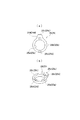
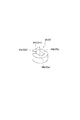
図1(a)、(b)は、本発明に係る2軸ヒンジを用いた端末機器の1例としてのノートパソコン1を示す。このノートパソコン1は、キーボード部2aを設けた第1筐体2と、ディスプレイ部3aを設けた第2筐体3の各後部の左右個所を、本発明に係る一対の2軸ヒンジ4と5で開閉可能に連結されている。   FIGS. 1A and 1B show a notebook computer 1 as an example of a terminal device using a biaxial hinge according to the present invention. The notebook computer 1 has a pair of biaxial hinges 4 and 5 according to the present invention on the left and right portions of the rear of the first housing 2 provided with the keyboard portion 2a and the second housing 3 provided with the display portion 3a. It is connected so that it can be opened and closed.

2軸ヒンジ4と5の構成は、両者共に同じ構成であるので、その一方の指示記号4のもののみを説明し、他方の指示記号5で示したものの説明は省略する。勿論、動作に支障がない場合には、指示記号5で示したヒンジの構造を別なものとしても良い。   The constructions of the biaxial hinges 4 and 5 are the same as each other, so only one of the indication symbols 4 will be described, and the explanation of the one indicated by the other indication symbol 5 will be omitted. Of course, in the case where there is no problem in the operation, the structure of the hinge indicated by the reference symbol 5 may be different.

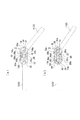
図2〜図17は、本発明に係る2軸ヒンジ4の一実施例を示す。とくに図2〜図4において、指示記号10と12で示したものは、第1ヒンジシャフトと第2ヒンジシャフトである。このうち第1ヒンジシャフト10からその構成を説明すると、とくに図4に示したように、その一端部側から断面扁平形状を呈し、その表面に取付孔10b、10b、10bを設けた取付板部10aと、この取付板部10aに続いて設けられた第1円形軸部10cと、この第1円形軸部10cに続いて設けられた第2円形軸部10dと、この第2円形軸部10dに続いて設けられた当該第2円形軸部10dよりやや小径の断面略楕円形状を呈した第1変形軸部10eと、この第1変形軸部10eに続いて設けられたところの当該第1変形軸部10eよりもさらに小径の同じく断面略楕円形状を呈して成る第2変形軸部10fと、この第2変形軸部10fに続いて設けられた雄ネジ部10gから構成されている。   2 to 17 show an embodiment of a biaxial hinge 4 according to the present invention. In particular, in FIGS. 2 to 4, those indicated by reference signs 10 and 12 are a first hinge shaft and a second hinge shaft. Among them, the first hinge shaft 10 will be described in particular. As shown in FIG. 4, the mounting plate portion has a flat shape in cross section from one end side and mounting holes 10b, 10b and 10b formed on the surface thereof. 10a, a first circular shaft portion 10c provided following the mounting plate portion 10a, a second circular shaft portion 10d provided subsequent to the first circular shaft portion 10c, and the second circular shaft portion 10d And a first deformation shaft portion 10e having a substantially elliptical cross-section with a diameter slightly smaller than that of the second circular shaft portion 10d, and a first deformation shaft portion 10e provided subsequently to the first deformation shaft portion 10e. A second deformation shaft portion 10f having a smaller diameter than that of the deformation shaft portion 10e and having a substantially elliptical cross section and a male screw portion 10g provided subsequent to the second deformation shaft portion 10f.

取付板部10aには、第1取付プレート11が取り付けられており、この第1取付プレート11の取付板部10aへの取付方法は、第1ヒンジシャフト10の取付孔10b、10b、10bと第1取付プレート11の取付孔(図示せず)を通したフランジ部付の取付ピン10h、10h、10hの各端部をかしめることによってなされている。そして、第1取付プレート11は、当該第1取付プレート11に設けた取付孔11b、11b・・(一部を図示)を介して、図示してない取付ネジを用いて第1筐体2の上面側へ取り付けられる構成である。尚、取付ピン10h、10h、10hはこれを取付ネジとしてもよい。   The first attachment plate 11 is attached to the attachment plate portion 10a. The attachment method of the first attachment plate 11 to the attachment plate portion 10a is the attachment holes 10b, 10b and 10b of the first hinge shaft 10 and the first attachment plate 10a. (1) It is made by caulking the end portions of the mounting pins 10h, 10h and 10h with the flange portion through the mounting holes (not shown) of the mounting plate 11. The first mounting plate 11 is mounted on the first housing 2 by means of mounting screws (not shown) via mounting holes 11b, 11b... (Partially shown) provided in the first mounting plate 11. It is a structure attached to the upper surface side. The mounting pins 10h, 10h and 10h may be used as mounting screws.

次に、指示記号12で示したものは、第1ヒンジシャフト10に対して上下方向へ平行に配置される第2ヒンジシャフトであり、この第2ヒンジシャフト12は、とくに図4に示したように、その一端部側から断面扁平形状を呈し、その表面に取付孔12b、12b、12bを設けた取付板部12aと、この取付板部12aに続いて設けられた第1円形軸部12cと、この第1円形軸部12cに続いて設けられた第2円形軸部12dと、この第2円形軸部12dに続いて設けられた当該第2円形軸部12dよりやや小径の断面略楕円形状を呈した第1変形軸部12eと、この第1変形軸部12eに続いて設けられたところの当該第1変形軸部12eよりもさらに小径の同じく断面略楕円形状を呈して成る第2変形軸部12fと、この第2変形軸部12fに続いて設けられた雄ネジ部12gから構成されている。   Next, what is indicated by a reference symbol 12 is a second hinge shaft disposed in parallel in the vertical direction with respect to the first hinge shaft 10, and this second hinge shaft 12 is particularly shown in FIG. A mounting plate 12a having a flat shape in cross section from one end side thereof and mounting holes 12b, 12b and 12b formed on the surface thereof, and a first circular shaft 12c provided following the mounting plate 12a A second circular shaft portion 12d provided following the first circular shaft portion 12c, and a cross-sectional substantially elliptical shape slightly smaller in diameter than the second circular shaft portion 12d provided subsequent to the second circular shaft portion 12d A second deformation shaft portion 12e having a shape similar to that of the first deformation shaft portion 12e having a diameter smaller than that of the first deformation shaft portion 12e provided next to the first deformation shaft portion 12e; Shaft 12f and this second deformation Following section 12f and a male screw portion 12g provided.

取付板部12aには、第2取付プレート13が取り付けられており、この第2取付プレート13の取付板部12aへの取付方法は、第2ヒンジシャフト12の取付孔12b、10b、12bと第2取付プレート13の取付孔13a、13a、13aを通したフランジ部付の取付ピン12h、12h、12hの各端部をかしめることによってなされている。そして、第2取付プレート13は、当該第2取付プレート13に設けた取付孔13b、13b・・を介して、図示してない取付ネジを用いて第2筐体3の下面側へ取り付けられる構成である。尚、取付ピン12h、12h、12hはこれを取付ネジとしてもよい。 The second attachment plate 13 is attached to the attachment plate portion 12a. The attachment method of the second attachment plate 13 to the attachment plate portion 12a is the attachment holes 12b, 10b and 12b of the second hinge shaft 12, and 2 is done by caulking the end portions of the mounting pins 12h, 12h, 12h with the flanges through the mounting holes 13a, 13a, 13a of the mounting plate 13. The second mounting plate 13 is mounted on the lower surface side of the second housing 3 using mounting screws (not shown) via the mounting holes 13b, 13b, ... provided in the second mounting plate 13. It is. The mounting pins 12h, 12h and 12h may be used as mounting screws.

そして、図2と図3に示したように、第1ヒンジシャフト10と第2ヒンジシャフト12は、その各第2円形軸部10d、12dを、第1連結部材14の上下位置に設けた各第1A軸受孔14a及び第1B軸受孔14bと、後述するフリクショントルク発生手段15のフリクションプレート16の上下位置に設けた一対の第2A軸受孔16a及び第2B軸受孔16bと、第1選択的回転規制手段22のスライドガイド部材21の上下位置に設けた一対の第3A軸受孔21d及び第3B軸受孔21eと、吸い込み手段46の第2連結部材37の上下位置に設けた一対の第4A軸受孔37d及び第4B軸受孔37eへ軸受されることにより、互いに平行、かつ回転自在に配置されている。そして、第1ヒンジシャフト10と第2ヒンジシャフト12は、第1取付プレート11と第2取付プレート13を第1筐体2と第2筐体3へ取り付けることにより、第1取付プレート11と第2取付プレート13を第1筐体2と第2筐体3の閉成状態において軸方向に対して垂直にかつ平行に配置される構成である。   As shown in FIGS. 2 and 3, the first hinge shaft 10 and the second hinge shaft 12 have their respective second circular shaft portions 10d, 12d provided at the upper and lower positions of the first connecting member 14. First selective bearing rotation 14a and first B bearing hole 14b, a pair of second A bearing hole 16a and second B bearing hole 16b provided at the upper and lower positions of friction plate 16 of friction torque generating means 15 described later, and first selective rotation A pair of third A bearing holes 21d and a third B bearing hole 21e provided at upper and lower positions of the slide guide member 21 of the restricting means 22, and a pair of fourth A bearing holes provided at upper and lower positions of the second connecting member 37 of the suction means 46 The bearings 37d and the 4B bearing holes 37e are disposed parallel to each other and rotatably. Then, the first hinge shaft 10 and the second hinge shaft 12 attach the first mounting plate 11 and the second mounting plate 13 to the first housing 2 and the second housing 3 to thereby form the first mounting plate 11 and the second hinge shaft 12. (2) The mounting plate 13 is arranged vertically and parallel to the axial direction in the closed state of the first housing 2 and the second housing 3.

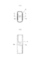
次に、図1〜図4と図17に指示記号6で示したものはヒンジケースであり、このヒンジケース6の中に第1ヒンジシャフト10と第2ヒンジシャフト12に取り付けた第1連結部材14から先の部分が収容されている。   Next, what is indicated by the reference symbol 6 in FIG. 1 to FIG. 4 and FIG. 17 is a hinge case, and a first connecting member attached to the first hinge shaft 10 and the second hinge shaft 12 in the hinge case 6 The part from 14 is accommodated.

このヒンジケース6は、とくに図2と図17に示したように、断面長孔形状を示した筒状のものであり、その内部に第1ヒンジシャフト10と第2ヒンジシャフト12に装備したフリクショントルク発生手段15、第2選択的回転規制手段23、第1選択的回転規制手段22、ストッパー手段47、及び吸い込み手段46が収容され、とくに図17に示したように、ヒンジケース6内に設けた挿通孔6bを有する隔壁6aを、第1選択的回転規制手段22の第2連結部材37の中央部に設けた突出部37gの雌ネジ孔37fに取付ネジ7で取り付けられる構成である。そして、このヒンジケース6は、とくに図2に示したように、第1筐体2と第2筐体3に設けた収容凹部2bと3b内に収容されている。また、もう一方のヒンジケース8も同じ構成である。   The hinge case 6 is a cylindrical one having a cross-sectionally elongated hole shape as shown in FIGS. 2 and 17 in particular, and the friction provided on the first hinge shaft 10 and the second hinge shaft 12 in the inside thereof. The torque generating means 15, the second selective rotation restricting means 23, the first selective rotation restricting means 22, the stopper means 47, and the suction means 46 are accommodated, and are provided in the hinge case 6 as particularly shown in FIG. The partition wall 6a having the insertion hole 6b is attached to the female screw hole 37f of the projecting portion 37g provided at the center of the second connection member 37 of the first selective rotation restricting means 22 by the mounting screw 7. The hinge case 6 is housed in the housing recesses 2b and 3b provided in the first housing 2 and the second housing 3 as particularly shown in FIG. Also, the other hinge case 8 has the same configuration.

次に、第1選択的回転規制手段22について説明する。この第1選択的回転規制手段22は、とくに図4に示したように、第1ヒンジシャフト10側の下部側の第1A選択的回転規制手段22aと上部側の第1B選択的回転規制手段22bとから成るが、上下対称になる以外は構成が同じであるので、ここではまとめて説明する。この第1選択的回転規制手段22は第2連結部材37と、ロック部材36と、スライドガイド部材21と、一対の第1Aロックカム部材34及び第1Bロックカム部材35とから構成されている。第2連結部材37は上部と下部の略円盤形状を呈した第1軸受部37a及び第2軸受部37bと、この第1及び第2軸受部37a、37b間をつなぐ連結部37cとを有する側面略瓢箪形状のもので、第1軸受部37a及び第2軸受部37bには、それぞれ断面円形状の第4A軸受孔37d及び第4B軸受孔37eが設けられ、この第1軸受孔4A及び第4B軸受孔37eに第1ヒンジシャフト10と第2ヒンジシャフト12のそれぞれの第2変形軸部10f、12fを挿通させて回転自在に軸受する構成である。第2連結部材37には、雌ネジ孔37fを設けた突出部37gが設けられ、この突出部37gは、上述したように取付ネジ7によって、ヒンジケース6の隔壁6aへ取り付けられる構成である。 Next, the first selective rotation restricting means 22 will be described. The first selective rotation restricting means 22 is, as particularly shown in FIG. 4, the first A selective rotation restricting means 22a on the lower side of the first hinge shaft 10 and the first B selective rotation restricting means 22b on the upper side. However, since the configuration is the same except that they are vertically symmetrical , they are collectively described here. The first selective rotation restricting means 22 comprises a second connection member 37, a lock member 36, a slide guide member 21, and a pair of first A lock cam members 34 and first B lock cam members 35. The second connecting member 37 has a side surface including a first bearing portion 37a and a second bearing portion 37b having a substantially disc shape in the upper and lower portions, and a connecting portion 37c connecting the first and second bearing portions 37a and 37b. The first bearing portion 37a and the second bearing portion 37b are substantially wedge-shaped, and are respectively provided with a fourth A bearing hole 37d and a fourth B bearing hole 37e having a circular cross section. The first bearing holes 4A and 4B are provided. The second deformed shaft portions 10f and 12f of the first hinge shaft 10 and the second hinge shaft 12 are inserted into the bearing holes 37e and rotatably supported. The second connecting member 37 is provided with a projection 37g provided with a female screw hole 37f, and the projection 37g is attached to the partition 6a of the hinge case 6 by the attachment screw 7 as described above.

ロック部材36は、とくに図13の(a)、(b)に示したように、その中央部の左右に、第1カム凸部36aと第2カム凸部36bを有し、この第1カム凸部36aと第2カム凸部36bを挟んで第1ガイド溝36cと第2ガイド溝36dが設けられている。そして、第2連結部材37の連結部37cは、ロック部材36の第1ガイド溝36c内に嵌入され、ロック部材36の上下方向のスライド動作をガイドしている。   The lock member 36 has a first cam convex portion 36a and a second cam convex portion 36b on the left and right of its central portion, as particularly shown in (a) and (b) of FIG. A first guide groove 36c and a second guide groove 36d are provided on both sides of the convex portion 36a and the second cam convex portion 36b. The connecting portion 37 c of the second connecting member 37 is fitted in the first guide groove 36 c of the lock member 36 to guide the sliding movement of the lock member 36 in the vertical direction.

スライドガイド部材21は、とくに図11に示したように、上部と下部に略円盤形状を呈した第1軸受部21aと第2軸受部21bと、この第1軸受部21a及び第2軸受部21b間をつなぐ連結部21cを有する瓢箪形状のもので、第1軸受部21aと第2軸受部21bには、第3A軸受孔21d及び第3B軸受孔21eが設けられ、これらの第3A軸受孔21dと第3B軸受孔21eに第1ヒンジシャフト10と第2ヒンジシャフト12の第1変形軸部10eと12eが挿通されて回転可能に軸受される構成である。連結部21cは、ロック部材36のもう一方の第2ガイド溝36d内に嵌入され、ロック部材36の上下方向のスライド動作をガイドしている。このスライドガイド部材21の第1軸受部21aと第2軸受部21bの外周部には、第1ストッパー部21fと第2ストッパー部21gが軸方向に突出して設けられている。   The slide guide member 21 is, as particularly shown in FIG. 11, a first bearing portion 21a and a second bearing portion 21b having a substantially disc shape at the upper and lower portions, and the first bearing portion 21a and the second bearing portion 21b. The first bearing portion 21a and the second bearing portion 21b are provided with a third A bearing hole 21d and a third B bearing hole 21e, and these third A bearing holes 21d are provided. The first hinge shaft 10 and the first deformation shafts 10e and 12e of the second hinge shaft 12 are inserted into the third bearing hole 21e and rotatably supported. The connecting portion 21 c is fitted into the other second guide groove 36 d of the lock member 36 and guides the sliding movement of the lock member 36 in the vertical direction. A first stopper portion 21f and a second stopper portion 21g are provided on the outer peripheral portion of the first bearing portion 21a and the second bearing portion 21b of the slide guide member 21 so as to project in the axial direction.

次に、第1Aロックカム部材34と第1Bロックカム部材35は上下一対のもので、下側第1Aロックカム部材34と上側の第1Bロックカム部材35には、それぞれ変形挿通孔34a、35aが設けられ、この変形挿通孔34a、35aへ第1ヒンジシャフト10と第2ヒンジシャフト12の各第1変形軸部10e、12eが挿通係合されることにより、この第1Aロックカム部材34と第1Bロックカム部材35は、第1ヒンジシャフト10と第2ヒンジシャフト12の第1変形軸部10eと第1変形軸部12eにそれぞれ回転を拘束されて取り付けられている。この第1Aロックカム部材34と第1Bロックカム部材35は、左右対称の同じ形状のものであり、とくに図12に示したように、それぞれ外周に90度間隔で軸方向両端部に達する第1Aカム凹部34b及び第2Aカム凹部34cと第1Bカム凹部35b及び第2Bカム凹部35cが設けられていると共に、組み立てた際にスライドガイド部材21側に位置する側には、その回転角度によって、スライドガイド部材21に設けた第1ストッパー部21fと第2ストッパー部21gに当接する第1ストッパー片34dと第2ストッパー片35dが設けられている。そして、その第1Aロックカム部材34と第1Bロックカム部材35は、第2連結部材37とスライドガイド部材21の間に軸方向に挟まれると共に、ロック部材36を挟んでその上部側と下部側に位置しており、それぞれの第1Aカム凹部34b及び第2Aカム凹部34cと第1Bカム凹部35bと第2Bカム凹部35cは、ロック部材36の第1カム凸部36aと第2カム凸部36bとに、その回転角度により対向して嵌合する構成である。 Next, the first 1A locking cam member 34 is first 1B locking cam member 35 intended vertical pair, on the lower side of the 1A locking cam member 34 and the upper first 1B locking cam member 35, respectively deformed insertion holes 34a, 35a are provided The first A lock cam member 34 and the first B lock cam member are engaged by inserting and engaging the first hinge shafts 10 and the first hinge shafts 12 of the first hinge shaft 12 to the hinge insertion holes 34a, 35a. The reference numeral 35 is attached to the first hinge shaft 10 and the first deformation shaft 10 e and the first deformation shaft 12 e of the second hinge shaft 12 while being restricted in rotation. The first A lock cam member 34 and the first B lock cam member 35 have the same shape in the left-right symmetry, and particularly, as shown in FIG. The slide guide member 34b is provided with a second A cam recess 34c, a first B cam recess 35b and a second B cam recess 35c, and a side located on the slide guide member 21 side when assembled, depending on its rotation angle. A first stopper piece 34d and a second stopper piece 35d which abut on the first stopper portion 21f and the second stopper portion 21g provided on the surface 21 are provided. The first A lock cam member 34 and the first B lock cam member 35 are axially sandwiched between the second connection member 37 and the slide guide member 21 and positioned on the upper side and the lower side with the lock member 36 interposed therebetween. The first A cam recess 34b, the second A cam recess 34c, the first B cam recess 35b, and the second B cam recess 35c correspond to the first cam protrusion 36a and the second cam protrusion 36b of the lock member 36, respectively. And are configured to be opposed and fitted by the rotation angle.

次に、第2選択的回転規制手段23は、とくに図2〜図4に示したように、第1ヒンジシャフト10側に設けられた下部側の第2A選択的回転規制手段23aと、第2ヒンジシャフト12側に設けられた上部側の第2B選択的回転規制手段23bとから成り、それぞれ第2Aフリクションワッシャー部19及び第2Bフリクションワッシャー部20に隣接している。この下部側の第2A選択的回転規制手段23aと上部側の第2B選択的回転規制手段23bは、それぞれ構成が上下対称となる点を除けばその構成は同じであるので、ここでは一緒に説明する。第2選択的回転規制手段23は、第1ヒンジシャフト10と第2ヒンジシャフト12の各第1変形軸部10e、12eに、その中心部軸方向に設けた変形挿通孔24c、25cを挿通係合させて設けた一対の第2Aロックカム部材24及び第2Bロックカム部材25と、この各第2Aロックカム部材24と第2Bロックカム部材25の間に位置してフリクションプレート16の中央部に設けた雌ネジ孔16cへストッパーホルダー27を介して回転可能に取り付けられた移動ストッパー26と、それぞれ筒部32b、33bと挿通孔32a、33aとフランジ部32c、33cを有し、挿通孔32a、33aに挿通させた第1変形軸部10e、12eに取り付けられた第1スペーサー部材32及び第2スペーサー部材33と、この各第1スペーサー部材32及び第2スペーサー部材33の各筒部32b、33bを、その挿通孔30a、31aに挿通させてフランジ部32c、33c側に設けたそれぞれ皿バネから成る第1A弾性手段30及び第1B弾性手段31と、この第1A及び第1B弾性手段30、31に接し、その各挿通孔28a、29aに筒部32b、33bを挿通させつつ第2Aロックカム部材24と第2Bロックカム部材25の間に設けられた第1ストッパーレバー28及び第2ストッパーレバー29とで構成されている。   Next, as shown in FIGS. 2 to 4 in particular, the second selective rotation restricting means 23 is provided with the second A selective rotation restricting means 23a on the lower side provided on the side of the first hinge shaft 10, and It is composed of an upper second B selective rotation restricting means 23b provided on the hinge shaft 12 side, and is adjacent to the second A friction washer part 19 and the second B friction washer part 20, respectively. The second A selective rotation restricting means 23a on the lower side and the second B selective rotation restricting means 23b on the upper side have the same structure except that the structure is vertically symmetrical, so that they will be described together here. Do. The second selective rotation restricting means 23 inserts the deformation insertion holes 24c, 25c provided in the axial direction of the central portion in the first deformation shaft portions 10e, 12e of the first hinge shaft 10 and the second hinge shaft 12, respectively. A pair of second A lock cam member 24 and second B lock cam member 25 provided in combination, and a female screw provided in the central portion of the friction plate 16 between the second A lock cam member 24 and the second B lock cam member 25 The movable stopper 26 rotatably attached to the hole 16c via the stopper holder 27, the cylindrical portions 32b and 33b, the insertion holes 32a and 33a, and the flange portions 32c and 33c, respectively, and the insertion holes 32a and 33a are inserted. A first spacer member 32 and a second spacer member 33 attached to the first deformed shaft portions 10e and 12e; The first A elastic means 30 and the first B made of disc springs provided on the flanges 32c and 33c side by inserting the cylindrical parts 32b and 33b of the bearing member 32 and the second spacer member 33 into the insertion holes 30a and 31a. Between the second A lock cam member 24 and the second B lock cam member 25 while making contact with the elastic means 31 and the first A and first B elastic means 30, 31 and inserting the cylindrical parts 32b, 33b into the respective insertion holes 28a, 29a. It is comprised by the provided 1st stopper lever 28 and the 2nd stopper lever 29. As shown in FIG.

第2Aロックカム部材24と第2Bロックカム部材25は、とくに図5と図6に示したように、それぞれその各一側面部24a、25a側の外周部に溝部a〜溝部dと溝部e〜溝部hが設けられるとともに、その他側面部24b、25bの側には複数の係止部i〜係止部mと係止部n〜係止部sが設けられており、溝部a〜溝部dと溝部e〜溝部hの位置は、第1ヒンジシャフト10側のものと第2ヒンジシャフト12側のものとでは同じであるが、係止部i〜係止部mと係止部n〜係止部sの形状は、若干異なっている。このように係止部i〜mと係止部n〜rの形が異なっているのは、後述するように、第1筐体2と第2筐体3の開閉方向により、第1ヒンジシャフト10と第2ヒンジシャフト12の回転方向が異なることになるからである。   The second A lock cam member 24 and the second B lock cam member 25 are, as particularly shown in FIGS. 5 and 6, groove a to groove d and groove e to groove h on the outer peripheral portion on the side surface 24a, 25a side respectively Are provided, and a plurality of locking portions i to m and locking portions n to s are provided on the side of the other side surface portions 24b and 25b, and the grooves a to d and the grooves e are provided. The position of the groove h is the same on the first hinge shaft 10 side and the second hinge shaft 12 side, but the locking portion i to the locking portion m and the locking portion n to the locking portion s The shape of is slightly different. The reason why the shapes of the locking portions i to m and the locking portions n to r are different from each other is the first hinge shaft according to the opening / closing direction of the first housing 2 and the second housing 3 as described later. This is because the rotational directions of the second hinge shaft 12 and the second hinge shaft 12 are different.

移動ストッパー26は、とくに図7に示したように、その中心部軸方向に挿通孔26aを設けた筒状部26bと、この筒状部26bの外周から180度間隔で外側へ突設させた一対の係合片26c、26cと、この各係合片26c、26cより軸方向へ突設した円弧状を呈した一対の係止片26d、26dとで構成され、その挿通孔26aへ挿通させたフランジ部27a付きのストッパーホルダー27の軸部27bを中心にして軸回りに回転可能である。係合片26c、26cには、第1係合部26c1、第2係合部26c2、第3係合部26c3、及び第4係合部26c4が設けられている。   As shown in FIG. 7 in particular, the movable stopper 26 is protruded outward at an interval of 180 degrees from the outer periphery of the cylindrical portion 26b provided with the insertion hole 26a in the axial direction of the central portion thereof. A pair of engaging pieces 26c, 26c and a pair of engaging pieces 26d, 26d having a circular arc shape protruding in the axial direction from the engaging pieces 26c, 26c are inserted into the insertion holes 26a. It is rotatable about an axis around a shaft portion 27b of the stopper holder 27 with the flange portion 27a. A first engagement portion 26c1, a second engagement portion 26c2, a third engagement portion 26c3, and a fourth engagement portion 26c4 are provided on the engagement pieces 26c, 26c.

一対の第1ストッパーレバー28と第2ストッパーレバー29は、同じ形状のもので、とくに図8の(a)、(b)に示したように、それぞれ挿通孔28a、29aを設けたリング状の各本体部28b、29bから外方向へ押圧片28c、29cを突設させると共に、本体部28b、29bには180度間隔で一対の突起部28d、28d・29d、29dが設けられており、それぞれの挿通孔28a、29aに第1及び第2スペーサー部材32、33の筒部32b、33bを挿通させる構成である。   The pair of first stopper levers 28 and the second stopper lever 29 have the same shape, and in particular, as shown in (a) and (b) of FIG. 8, a ring shape provided with insertion holes 28a and 29a respectively. While pressing pieces 28c and 29c are protruded outward from the respective main body portions 28b and 29b, a pair of protruding portions 28d, 28d and 29d and 29d are provided on the main body portions 28b and 29b at intervals of 180 degrees, respectively. The cylindrical portions 32b and 33b of the first and second spacer members 32 and 33 are inserted into the insertion holes 28a and 29a.

一対の第1スペーサー部材32及び第2スペーサー部材33は、とくに図10に示したように、同じ形状であり、それぞれ挿通孔32a、33aを設けた筒部32b、33bと、筒部32b、33bに設けたフランジ部32c、33cとを設けたもので、第1ヒンジシャフト10と第2ヒンジシャフト12の各第1変形軸部10e、12eを挿通孔32a、33aに挿通させている。   The pair of first spacer members 32 and the second spacer members 33 have the same shape, as particularly shown in FIG. 10, and have cylindrical portions 32b and 33b provided with insertion holes 32a and 33a, and cylindrical portions 32b and 33b, respectively. The flange portions 32c and 33c provided on the upper and lower sides of the first hinge shaft 10 and the second hinge shaft 12 are inserted into the insertion holes 32a and 33a, respectively.

一対の第1A弾性手段30と第1B弾性手段31は、とくに図9に示したように、高さの低い切頭円錐形状を呈したもので、それぞれの挿通孔30a、31aに第1及び第2スペーサ―部材32、33の筒部32b、33bを挿通させ、第1ストッパーレバー28と第2ストッパーレバー29の各本体部28b、29bと第1スペーサー部材32及び第2スペーサー部材33の各フランジ部32c、33cとの間に弾設される構成であり、それぞれが当接する第1ストッパーレバー28及び第2ストッパーレバー29に第2Aロックカム部材24と第2Bロックカム部材25の各面部との間で、フリクショントルクが発生するものである。   The pair of first A elastic means 30 and the first B elastic means 31 have a frusto-conical shape with a low height, as shown particularly in FIG. The cylinder portions 32b and 33b of the spacer members 32 and 33 are inserted, and the body portions 28b and 29b of the first stopper lever 28 and the second stopper lever 29 and the flanges of the first spacer member 32 and the second spacer member 33 The first stopper lever 28 and the second stopper lever 29 are in contact with each other between the second A lock cam member 24 and the second B lock cam member 25. , Friction torque is generated.

次に、第1ヒンジシャフト10と第2ヒンジシャフト12の回転時にフリクショントルクを発生させるフリクショントルク発生手段15について説明する。このフリクショントルク発生手段15は、第1ヒンジシャフト10側の第1フリクション発生手段15aと、第2ヒンジシャフト12側の第2フリクション発生手段15bとから成り、それぞれ第1ヒンジシャフト10と第2ヒンジシャフト12の各第1変形軸部10e、12eをその第2A軸受孔16a及び第2B軸受孔16bに軸受させている片面略瓢箪形状を呈したフリクションプレート16と、このフリクションプレート16の一側面側と第1連結部材14との間に、それぞれ中心部軸方向に設け、各変形挿通孔17e及び変形挿通孔18eに、各第1変形軸部10e、12eを挿通係合させて設けた、実施例ではそれぞれ3枚ずつのフリクションワッシャー17a、17b、17cと18a、18b、18cから成る第1Aフリクションワッシャー部17及び第1Bフリクションワッシャー部18と、フリクションプレート16の他側面側と後述する第2選択的回転規制手段23の第2Aロックカム部材24と第2Bロックカム部材25の各一側面との間に、それぞれ中心部軸方向に設けた変形挿通孔19a、20aに各第1変形軸部10e、12eを挿通させて設けた、実施例では1枚のフリクションワッシャーから成る第2Aフリクションワッシャー部19及び第2Bフリクションワッシャー部20と、第1Aフリクションワッシャー部17及び第1Bフリクションワッシャー部18をフリクションプレート16へ圧接するための後述する吸い込み手段46の第2A弾性手段40及び第2B弾性手段41とで構成されている。尚、図4において、指示記号17d、18d、19b、20bで示されたものは、潤滑用のオイル溜部である。   Next, friction torque generating means 15 for generating friction torque when the first hinge shaft 10 and the second hinge shaft 12 rotate will be described. The friction torque generating means 15 comprises a first friction generating means 15a on the first hinge shaft 10 side and a second friction generating means 15b on the second hinge shaft 12 side, and the first hinge shaft 10 and the second hinge respectively. A friction plate 16 having a single-sided, substantially wedge shape, in which the first deformation shaft portions 10e and 12e of the shaft 12 are supported by the second A bearing hole 16a and the second B bearing hole 16b, and one side of the friction plate 16 Between the first connection member 14 and in the central axial direction, and the first deformation shaft portions 10e and 12e are inserted into and engaged with the deformation insertion holes 17e and the deformation insertion holes 18e, respectively. In the example, a first A-flick comprising three friction washers 17a, 17b, 17c and 18a, 18b, 18c, respectively. Between the second A lock cam member 24 and the second B lock cam member 25 of the second selective rotation restricting means 23 to be described later and the second side of the friction plate 16 and the second side of the friction plate 16 In the embodiment, the second A friction washer portion 19 and the first friction shaft portion 19 are formed by inserting the first deformation shaft portions 10e and 12e into the deformation insertion holes 19a and 20a provided in the central axial direction, respectively. A second B elastic means 40 and a second B elastic means 41 of suction means 46 described later for pressing the second B friction washer part 20 and the first A friction washer part 17 and the first B friction washer part 18 into pressure contact with the friction plate 16 It is done. In FIG. 4, those indicated by reference symbols 17d, 18d, 19b and 20b are oil reservoirs for lubrication.

次に、吸い込み手段46は、下側の第1ヒンジシャフト10側の第1吸い込み手段46aと、上側の第2ヒンジシャフト12側の第2吸い込み手段46bとから成るが、構成が同じであるので、ここではまとめて説明する。第1吸い込み手段46aと第2吸い込み手段46bは、第2連結部材37の各第1及び第2軸受部37a、37bの側面部の外側と内側に設けた大小の第1A湾曲カム凹部37h及び第1B湾曲カム凹部37iと第2A湾曲カム凹部37j及び第2B湾曲カム凹部37kと、その各変形挿通孔38a、39aを第1ヒンジシャフト10と第2ヒンジシャフト12の第2変形軸部10f、12fを挿通係合させると共に、その側面の外側と内側に設けた大小の第1A湾曲カム凸部38b及び第1B湾曲カム凸部38cと第2A湾曲カム凸部39b及び第2B湾曲カム凸部39cを、第2連結部材37の各第1及び第2軸受部37a、37bの側面部の外側と内側に設けた大小の第1A湾曲カム凹部37h及び第1B湾曲カム凹部37iと第2A湾曲カム凹部37j及び第2B湾曲カム凹部37kと対向させて設けられた第1カムフォロワー38及び第2カムフォロワー39と、この第1カムフォロワー38及び第2カムフォロワー39に接してその中心部軸方向に設けた各挿通孔40a、41aへ第1ヒンジシャフト10と第2ヒンジシャフト12の各第2変形軸部10f、12fを挿通させて設けた複数の皿バネ40bと41bから成る第2A弾性手段40及び第2B弾性手段41と、この第2A弾性手段40と第2B弾性手段41に接してその中心部軸方向に設けた変形挿通孔42a、43aに第1ヒンジシャフト10と第2ヒンジシャフト12の第2変形軸部10fと第2変形軸部12fを挿通係合させて設けた第1押えワッシャー42と第2押えワッシャー43と、第1ヒンジシャフト10と第2ヒンジシャフト12の各第2変形軸部10f、12fの自由端部側に設けた雄ネジ部10gと雄ネジ部12gに捻子着させた第1締付ナット44と第2締付ナット45とで構成されている。   Next, although the suction means 46 comprises the first suction means 46a on the lower first hinge shaft 10 side and the second suction means 46b on the upper second hinge shaft 12 side, the construction is the same. Here, we will explain together. The first suction means 46a and the second suction means 46b are provided on the outer and inner sides of the side portions of the first and second bearing portions 37a and 37b of the second connection member 37, respectively. The 1B curved cam concave portion 37i, the second A curved cam concave portion 37j, the second B curved cam concave portion 37k, and the respective deformation insertion holes 38a and 39a thereof are used as the second deformation shaft portions 10f and 12f of the first hinge shaft 10 and the second hinge shaft 12, respectively. And the first A curved cam convex portion 38b and the first B curved cam convex portion 38c, and the second A curved cam convex portion 39b and the second B curved cam convex portion 39c provided on the outer side and the inner side of the side surface thereof. The first and second curved cam recesses 37h and the first B curved cam recesses 37i and the second A provided on the outside and the inside of the side surfaces of the first and second bearings 37a and 37b of the second connecting member 37. A first cam follower 38 and a second cam follower 39 provided opposite to the curved cam recess 37j and the second B curved cam recess 37k, and a central axis in contact with the first cam follower 38 and the second cam follower 39 Second A-elasticity composed of a plurality of disc springs 40b and 41b provided by inserting the second hinged shafts 10f and 12f of the first hinge shaft 10 and the second hinge shaft 12 into the insertion holes 40a and 41a provided in the same direction. Means 40 and the second B elastic means 41, and the first hinge shaft 10 and the second hinge shaft in the deformation insertion holes 42a and 43a provided in the central axial direction in contact with the second A elastic means 40 and the second B elastic means 41 A first pressing washer 42 and a second pressing washer 43, which are provided by inserting and engaging the second deformation shaft portion 10f and the second deformation shaft portion 12f; Male screw 10g provided on the free end side of each of the second deformation shaft 10f and 12f of the shaft 10 and the second hinge shaft 12, and a first tightening nut 44 and a second screw fixed to the male screw 12g. It consists of an attached nut 45.

そして、ストッパー手段47も、第1ヒンジシャフト10側の第1ストッパー手段47aと、第2ヒンジシャフト12側の第2ストッパー手段47bとから成るが、両者は構成が同じなので、ここではまとめて説明する。この第1ストッパー手段47aと第2ストッパー手段47bは、第1Aロックカム部材34及び第1Bロックカム部材35に設けた第1ストッパー片34d及び第2ストッパー片35dと、スライドガイド部材21の第1軸受部21a及び第2軸受部21bに設けた第1ストッパー部21f及び第2ストッパー部21gとで構成されており、第1筐体2と第2筐体3の閉成状態の位置(0度)と全開成状態(180度)の位置を規制するものである。   And although the stopper means 47 also consists of the 1st stopper means 47a by the side of the 1st hinge shaft 10, and the 2nd stopper means 47b by the side of the 2nd hinge shaft 12, since both configurations are the same, they are collectively explained here. Do. The first stopper means 47a and the second stopper means 47b comprise a first stopper piece 34d and a second stopper piece 35d provided on the first A lock cam member 34 and the first B lock cam member 35, and a first bearing portion of the slide guide member 21. 21a and a second stopper portion 21g provided on the second bearing portion 21b, and the position (0 degree) of the closed state of the first housing 2 and the second housing 3 It regulates the position in the fully open state (180 degrees).

次に、上記した本発明に係る2軸ヒンジ4の動作について以下に説明する。まず、本発明に係る2軸ヒンジ4は、端末機器の1例であるノートパソコン1を構成する第1筐体2と第2筐体3を相対的に開閉させる2軸ヒンジである。その特徴は、第1筐体2側へ取り付けられる第1ヒンジシャフト10と、第2筐体3側へ取り付けられる第2ヒンジシャフト12とを少なくとも第1連結部材14と第2連結部材37とで平行状態に連結して互いに回転可能に設けたもので、第1筐体2と第2筐体3を相対的に開閉させると、第1選択的回転規制手段22と第2選択的回転規制手段23が順次交互に動作し、所定の順序で開閉され、第1筐体2と第2筐体3を相対的に0度から360度の範囲に渡って開閉させる点にある。しかしながら、その開閉順序は、下記実施例のものに限定されない。 Next, the operation of the biaxial hinge 4 according to the present invention described above will be described below. First, the biaxial hinge 4 according to the present invention is a biaxial hinge that relatively opens and closes the first housing 2 and the second housing 3 that constitute the notebook computer 1 that is an example of the terminal device. The feature is that the first hinge shaft 10 attached to the first housing 2 side and the second hinge shaft 12 attached to the second housing 3 are at least the first connecting member 14 and the second connecting member 37. The first selective rotation restricting means 22 and the second selective rotation restricting means are connected to each other in a parallel state and provided rotatably relative to each other, when the first housing 2 and the second housing 3 are opened and closed relative to each other. 23 sequentially operate alternately and open and close in a predetermined order, and open and close the first casing 2 and the second casing 3 over a range of 0 degrees to 360 degrees relative to each other. However, the order of opening and closing is not limited to that of the following embodiment.

即ち、実施例のものは、まず、ノートパソコン1の第1筐体2と第2筐体3の閉成状態の開閉角度0度の時から90度までの開閉時には、図18〜図20に示したように、第1選択的回転規制手段22によって、第1ヒンジシャフト10の時計方向の回転が可能となって、第2ヒンジシャフト12の回転は阻止されるので、第2筐体3に対して第1筐体2が開閉される。90度から180度までの開閉時には、図21と図22に示したように、第1選択的回転規制手段22によって、今度は第1ヒンジシャフト10と第2ヒンジシャフト12はともに回転可能となるが、第2選択的回転規制手段23によって、第1ヒンジシャフト10のさらなる時計方向の回転が阻止されるので、第2ヒンジシャフト12の反時計方向の回転が可能になることから、第1筐体2に対して第2筐体3を開くことが可能となり、この第2筐体3が第1筐体2に対して両者の開成角度が180度になるまで開かれる。 That is, first, when the first case 2 and the second case 3 of the notebook computer 1 are opened or closed from 0 degrees to 90 degrees in the closed state of the notebook computer 1 , FIGS. As shown, since the first selective rotation restricting means 22 enables the clockwise rotation of the first hinge shaft 10 and prevents the rotation of the second hinge shaft 12, the second housing 3 is provided. In contrast, the first case 2 is opened and closed. At the time of opening and closing from 90 degrees to 180 degrees, as shown in FIGS. 21 and 22, the first hinge shaft 10 and the second hinge shaft 12 can be rotated together by the first selective rotation restricting means 22 this time. However, since the second selective rotation restricting means 23 prevents further clockwise rotation of the first hinge shaft 10, the counterclockwise rotation of the second hinge shaft 12 is enabled, so that the first housing It is possible to open the second housing 3 with respect to the body 2 and the second housing 3 is opened with respect to the first housing 2 until the opening angle between the two is 180 degrees.

この180度から270度までの開閉時には、図23と図24に示したように、第1選択的回転規制手段22により、第1ヒンジシャフト10と第2ヒンジシャフト12は、共に回転可能になるが、第2選択的回転規制手段23により、第2ヒンジシャフト12の反時計方向の回転が規制される結果、今度は第1ヒンジシャフト10の時計方向の回転が可能となり、第1筐体2は第2筐体3に対して、両者の開成角度が270度になるまで開かれることになる。   At the time of opening and closing from 180 degrees to 270 degrees, as shown in FIGS. 23 and 24, the first hinge shaft 10 and the second hinge shaft 12 can be rotated together by the first selective rotation restricting means 22. However, as a result of the counterclockwise rotation of the second hinge shaft 12 being restricted by the second selective rotation restricting means 23, the clockwise rotation of the first hinge shaft 10 becomes possible this time, and the first housing 2 Is opened with respect to the second housing 3 until the opening angle of the both is 270 degrees.

この270度まで開かれると、図25と図26に示したように、第1選択的回転規制手段22により、第1ヒンジシャフト10と第2ヒンジシャフト12はともに回転可能であるが、第2選択的回転規制手段23により、第1ヒンジシャフト10の時計方向の回転が規制される結果、今度は第2ヒンジシャフト12の反時計方向の回転が可能となり、第2筐体3第1筐体2に対して360度になるまで開かれることになる。そして、360度まで開かれると、図26に示したように、第1選択的回転規制手段22によって、第1ヒンジシャフト10の回転は規制され、第2選択的回転規制手段23によって、今度は閉成方向に向かって第2ヒンジシャフト12の時計方向の回転が許容されることになる。 When it is opened to 270 degrees, as shown in FIGS. 25 and 26, the first hinge shaft 10 and the second hinge shaft 12 can rotate together by the first selective rotation restricting means 22, but As a result of the clockwise rotation of the first hinge shaft 10 being restricted by the selective rotation restricting means 23, the counterclockwise rotation of the second hinge shaft 12 becomes possible this time, and the second housing 3 becomes the first housing. It will be opened up to 360 degrees to the body 2 . Then, when the hinge shaft is opened up to 360 degrees, as shown in FIG. 26, the rotation of the first hinge shaft 10 is restricted by the first selective rotation restricting means 22, and the second selective rotation restricting means 23 in turn Clockwise rotation of the second hinge shaft 12 is permitted in the closing direction.

以下にさらに詳しく説明するが、本発明に係る2軸ヒンジ4にあっては、第2選択的回転規制手段23の動作が複雑なので、この動作を先に説明する。この第2選択的回転規制手段23の移動ストッパー26の回転によって、第1ヒンジシャフト10と第2ヒンジシャフト12の回転を規制したり許容したりするが、この移動ストッパー26を回転させるのは、第1及び第2ストッパーレバー28、29である。それぞれ第1A弾性手段30と第1B弾性手段31によって、第2Aロックカム部材24と第2Bロックカム部材25の各一側面部24a、25aの側にそれぞれ圧接されている。したがって、第1及び第2ストッパーレバー28、29は、第2Aロックカム部材24と第2Bロックカム部材25が回転する際には、フリクショントルクによって共に回転する構成となっている。第1及び第2ストッパーレバー28、29は、上述したように、それぞれ一対の突起部28d、28d・29d、29dが180度間隔で設けられている。図5と図6の各(a)に示したように、第2Aロックカム部材24側の各溝部a〜dと第2Bロックカム部材25側の各溝部e〜hについては、第1筐体2と第2筐体3が閉じられた閉成状態の時には、第1ストッパーレバー28に設けた突起部28d、28dは、第2Aロックカム部材24の溝部aとcの中に落ち込んでおり、第2ストッパーレバー29に設けた突起部29d、29dは、第2Bロックカム部材25の溝部eとgの中に落ち込んでいる。他方、移動ストッパー26の係合片26c、26cのうち第1係合部26c1は、第2Aロックカム部材24の係止部iと係合し、第4係合部26c4は、第2Bロックカム部材25の係止部nと係合している。したがって、図5と図6の各(b)の各係止部iとnの形状から解るように、第2選択的回転規制手段23においても、第2Aロックカム部材24は、時計方向の回転を許容され、第2Bロックカム部材25は、反時計方向の回転を規制されている。   As described in more detail below, in the case of the biaxial hinge 4 according to the present invention, the operation of the second selective rotation restricting means 23 is complicated, so this operation will be described first. The rotation of the movable stopper 26 of the second selective rotation restricting means 23 restricts or allows the rotation of the first hinge shaft 10 and the second hinge shaft 12, but the movable stopper 26 is rotated as follows: The first and second stopper levers 28 and 29 are provided. The first A elastic means 30 and the first B elastic means 31 press-contact the side surfaces 24 a and 25 a of the second A lock cam member 24 and the second B lock cam member 25. Accordingly, when the second A lock cam member 24 and the second B lock cam member 25 rotate, the first and second stopper levers 28 and 29 rotate together by the friction torque. As described above, the first and second stopper levers 28, 29 are provided with a pair of protrusions 28d, 28d, 29d, 29d at an interval of 180 degrees. As shown in FIGS. 5 and 6 (a), the grooves a to d on the second A lock cam member 24 and the grooves e to h in the second B lock cam member 25 correspond to the first housing 2 and In the closed state where the second housing 3 is closed, the protrusions 28d, 28d provided on the first stopper lever 28 fall into the grooves a and c of the second A lock cam member 24, and the second stopper The protrusions 29 d, 29 d provided on the lever 29 are depressed into the grooves e and g of the second B lock cam member 25. On the other hand, the first engagement portion 26c1 of the engagement pieces 26c and 26c of the moving stopper 26 engages with the engagement portion i of the second A lock cam member 24, and the fourth engagement portion 26c4 is a second B lock cam member 25. Engaging with the locking part n of Therefore, as can be understood from the shapes of the locking portions i and n in (b) of FIGS. 5 and 6, also in the second selective rotation restricting means 23, the second A lock cam member 24 rotates clockwise. The second B lock cam member 25 is restricted from rotating in the counterclockwise direction.

第2Aロックカム部材24は、第1筐体2の第2筐体3に対する0度から90度と180度から270度の開成時にその回転を許容されるが、第1ストッパーレバー28の突起部28d、28dは、90度の時は溝部b、dの中に落ち込み、270度でc、aの中に落ち込むことになる。尚、閉成時にはその逆となる。 The second A lock cam member 24 is allowed to rotate at the time of opening from 0 ° to 90 °, 180 ° to 270 ° with respect to the second housing 3 of the first housing 2, but the projection 28 d of the first stopper lever 28 , 28d fall into the grooves b and d at 90 degrees and fall into c and a at 270 degrees . At the time of closure, the opposite is true.

他方、第2Bロックカム部材25は、第2筐体3の第1筐体2に対する90度から180度と270度から360度の開成時にその回転を許容され、第2ストッパーレバー29の突起部29d、29dは、180度の時は溝部f、hの中に落ち込み360度の時は溝部g、eの中に落ち込むことになる。尚、閉成時はその逆となる。 On the other hand, the second B lock cam member 25 is allowed to rotate at the time of opening from 90 degrees to 180 degrees, 270 degrees to 360 degrees with respect to the first housing 2 of the second housing 3, and the projection 29 d of the second stopper lever 29 , 29d fall into the grooves f, h at 180 degrees and fall into the grooves g, e at 360 degrees. At the time of closure, the opposite is true.

上記いずれの場合でも、第1及び第2ストッパーレバー28、29の各突起部28d、28dと29d、29dは、第2Aロックカム部材24と第2Bロックカム部材25の各溝部a〜dとe〜hから、第2Aロックカム部材24と第2Bロックカム部材25の回転に伴ってその各一側面部24aと25aに乗り上げた際にフリクショントルクが発生し、この摩擦力により、移動ストッパー26の各係止片26d、26dを押して回転させるものである。   In any of the above cases, the protrusions 28d, 28d and 29d, 29d of the first and second stopper levers 28, 29 are grooves a to d and e to h of the second A lock cam member 24 and the second B lock cam member 25. From this, friction torque is generated when the second A lock cam member 24 and the second B lock cam member 25 rotate on the respective side surface portions 24a and 25a, and the frictional force causes the locking pieces of the moving stopper 26 to be engaged. 26d and 26d are pushed and rotated.

これに対し、移動ストッパー26の係合片26c、26cの第1係合部26c1〜第4係合部26c4は、第1筐体2と第2筐体3の開成時において、第2Aロックカム部材24の時計方向の回転と、第2Bロックカム部材25の反時計方向の回転が規制されるときは、その回転が規制される係止部(指示記号は後述)と係合することになる。尚、閉成時はその逆となる。   On the other hand, the first engagement portion 26c1 to the fourth engagement portion 26c4 of the engagement pieces 26c and 26c of the movable stopper 26 are the second A lock cam members when the first case 2 and the second case 3 are opened. When the clockwise rotation of 24 and the counterclockwise rotation of the second B lock cam member 25 are restricted, it engages with a locking portion (designated symbol will be described later) whose rotation is restricted. At the time of closure, the opposite is true.

第1筐体2と第2筐体3の開閉動作をさらに詳しく説明すると、まず、第1筐体2と第2筐体3が閉じられた図1に示した閉成状態においては、図18の(a)に示したように、第1選択的回転規制手段22のロック部材36の第1カム凸部36aは、第1Aロックカム部材34の外周面と当接しており、第2カム凸部36bは第1Bロックカム部材35の第1Bカム凹部35bと係合している。したがって、この閉成状態においては、回転できるのは第1Aロックカム部材34を取り付けた第1ヒンジシャフト10の側であって、第2ヒンジシャフト12の側は回転できないことから、第2筐体3に対して第1筐体2が第1ヒンジシャフト10と共に時計方向へ回転して開かれることになる。この状態時の第2選択的回転規制手段23の移動ストッパー26の係合片26c、26cの第1係合部26c1は、上述したように、第2Aロックカム部材24側の係止部iと係合しているが、その係合方向は図面から明らかなように、第2Aロックカム部材24の時計方向の回転を規制するものではなく、これを許容するものであるので、第1ヒンジシャフト10の回転に支障を生じさせない。他方、第2ヒンジシャフト12側の第2Bロックカム部材25の係止部nに対しては、移動ストッパー26の係合片26cの第4係合部26c4が係合し、第2Bロックカム部材25の反時計方向の回転を規制する側に係止されていることから、この第2選択的回転規制手段23によっても、第2ヒンジシャフト12は、反時計方向の回転を規制されており、この第2ヒンジシャフト12は0度から90度に向けては回転しない。   The opening and closing operations of the first housing 2 and the second housing 3 will be described in more detail. First, in the closed state shown in FIG. 1 in which the first housing 2 and the second housing 3 are closed, FIG. As shown in (a), the first cam convex portion 36a of the lock member 36 of the first selective rotation restricting means 22 is in contact with the outer peripheral surface of the first A lock cam member 34, and the second cam convex portion 36 b is engaged with the first B cam recess 35 b of the first B lock cam member 35. Therefore, in the closed state, it is the side of the first hinge shaft 10 to which the first A lock cam member 34 is attached that can be rotated and the side of the second hinge shaft 12 can not be rotated. On the other hand, the first housing 2 is rotated clockwise with the first hinge shaft 10 to be opened. The first engaging portions 26c1 of the engaging pieces 26c and 26c of the movable stopper 26 of the second selective rotation restricting means 23 in this state are engaged with the engaging portions i on the second A lock cam member 24 as described above. However, as the engagement direction does not restrict the clockwise rotation of the second A lock cam member 24 but allows this, as shown in the drawing, the engagement direction of the first hinge shaft 10 Do not disturb the rotation. On the other hand, the fourth engaging portion 26c4 of the engaging piece 26c of the moving stopper 26 is engaged with the locking portion n of the second B lock cam member 25 on the second hinge shaft 12 side. Since the second selective rotation restricting means 23 also locks the second hinge shaft 12 in the counterclockwise direction, the second hinge shaft 12 is restricted in the counterclockwise direction because it is locked to the side that restricts the counterclockwise rotation. The two hinge shafts 12 do not rotate from 0 degrees to 90 degrees.

このようにして、第1ヒンジシャフト10の時計方向の回転がなされ、第1筐体2が第2筐体3に対して開かれて行く途中の状態が第19図に示してある。図面によれば、第1筐体2は、第2筐体3に対して第1ヒンジシャフト10を支点に回転して開かれて行くが、この際に、第2選択的回転制御手段23の移動ストッパー26は、第1及び第2ストッパーレバー28、29の押圧片28c、29cによって押される結果、反時計方向へ回転して行くことが解る。   Thus, the clockwise rotation of the first hinge shaft 10 is performed, and the state in which the first housing 2 is being opened relative to the second housing 3 is shown in FIG. According to the drawing, the first housing 2 is opened with respect to the second housing 3 with the first hinge shaft 10 as a fulcrum, and at this time, the first housing 2 is made of the second selective rotation control means 23. As a result of the movement stopper 26 being pushed by the pressing pieces 28c and 29c of the first and second stopper levers 28 and 29, it can be understood that the movement stopper 26 rotates in the counterclockwise direction.

次に、第1筐体2が第2筐体3に対し、90度まで開かれた状態は、図20に示してある。図面によれば、この状態において、第1選択的回転制御手段22のロック部材36の第1カム凸部36aは、第1Aロックカム部材34の第2Aカム凹部34cと対向し、第2カム凸部36bが第1Bロックカム部材35の第1Bカム凹部35bと対向している。   Next, a state in which the first housing 2 is opened up to 90 degrees with respect to the second housing 3 is shown in FIG. According to the drawing, in this state, the first cam convex portion 36a of the lock member 36 of the first selective rotation control means 22 faces the second A cam concave portion 34c of the first A lock cam member 34, and the second cam convex portion 36 b is opposed to the first B cam concave portion 35 b of the first B lock cam member 35.

したがって、第1筐体2が引き続き開かれるように見えるが、第2選択的回転規制手段23の移動ストッパー26が上述したように反時計方向に回転し、図20の(c)に示したように、その係合片26c、26cの第1係合部26c1と第3係合部26c3が係止部kとoと係合し、第1ヒンジシャフト10のそれ以上の回転を規制することになることから、第1筐体2は回転することができなくなる。これに対して、第2筐体3は第2選択的回転規制手段23の移動ストッパー26の係合片26cの第3係合部26c3が第1Bロックカム部材35の係止部oと係合しているが、その反時計方向の回転方向は規制されていないので、第2ヒンジシャフト12が90度以上に回転することを許容されることになる。したがって、第1筐体2と第2筐体3が90度開かれた以降は、第2筐体3が第1筐体2に対して開かれることになる。一方、第2筐体3に対して90度まで開かれた第1筐体2は、これを閉じ方向へ回転させることはできるので、第1筐体2を第2筐体3に対して閉じることができる。   Therefore, although it seems that the first housing 2 continues to be opened, the moving stopper 26 of the second selective rotation restricting means 23 rotates counterclockwise as described above, as shown in FIG. 20C. The first engaging portion 26c1 and the third engaging portion 26c3 of the engaging pieces 26c, 26c engage with the locking portions k and o to restrict further rotation of the first hinge shaft 10. As a result, the first housing 2 can not rotate. On the other hand, in the second housing 3, the third engaging portion 26 c 3 of the engaging piece 26 c of the movable stopper 26 of the second selective rotation restricting means 23 engages with the engaging portion o of the first B lock cam member 35. However, since the counterclockwise direction of rotation is not restricted, the second hinge shaft 12 is allowed to rotate 90 degrees or more. Therefore, after the first housing 2 and the second housing 3 are opened 90 degrees, the second housing 3 is opened relative to the first housing 2. On the other hand, since the first housing 2 opened up to 90 degrees with respect to the second housing 3 can be rotated in the closing direction, the first housing 2 is closed to the second housing 3 be able to.

次に、第2筐体3が第1筐体2に対して90度から180度の方向へ開かれて行く途中の状態は、図21に示されている。図面によれば、移動ストッパー26が第1及び第2ストッパーレバー28、29によって今度は時計方向へ回転して行くのが解る。   Next, the state in the middle of the second housing 3 being opened in the direction of 90 degrees to 180 degrees with respect to the first housing 2 is shown in FIG. According to the drawing, it can be seen that the moving stopper 26 is now rotated clockwise by the first and second stopper levers 28 and 29.

第2筐体3が第1筐体2に対して180度まで開かれた状態は、図22に示されている。図面によれば、第1選択的回転規制手段22のロック部材36の第1カム凸部36aと第2カム凸部36bは、第1Aロックカム部材34と第1Bロックカム部材35のそれぞれ第2Aカム凹部34c及び第2Bカム凹部35cと対向することになり、第1ヒンジシャフト10と第2ヒンジシャフト12はどちらも回転可能に見える。しかしながら、第2選択的回転規制手段23の移動ストッパー26が、図22の(c)に示したように、第1及び第2ストッパーレバー28、29によって時計方向に回転させられ、その係合片26c、26cの第1係合部26c1と第4係合部26c4が第2Aロックカム部材24と第2Bロックカム部材25の係止部jとqと係合することになるため、その係合方向により、第2筐体3の反時計方向の回転は規制される。その結果、今度は第1筐体2の第2筐体3に対する270度に向けての時計方向の回転が可能となる。   The state in which the second housing 3 is opened up to 180 degrees with respect to the first housing 2 is shown in FIG. According to the drawing, the first cam convex portion 36a and the second cam convex portion 36b of the lock member 36 of the first selective rotation restricting means 22 are respectively the second A cam concave portions of the first A lock cam member 34 and the first B lock cam member 35. The first hinge shaft 10 and the second hinge shaft 12 appear to be rotatable, as opposed to the 34c and the second B cam recess 35c. However, the moving stopper 26 of the second selective rotation restricting means 23 is rotated clockwise by the first and second stopper levers 28 and 29 as shown in FIG. The first engaging portion 26c1 and the fourth engaging portion 26c4 of 26c and 26c engage with the locking portions j and q of the second A lock cam member 24 and the second B lock cam member 25. The counterclockwise rotation of the second housing 3 is restricted. As a result, clockwise rotation of the first housing 2 relative to the second housing 3 to 270 degrees is possible this time.

次に、第1筐体2が第2筐体3に対して270度まで開かれる途中の状態は、図23に示されている。図面によれば、第2選択的回転規制手段23の移動ストッパー26は、今度は第1及び第2ストッパーレバー28、29により、反時計方向へ回転して行く。   Next, a state in which the first housing 2 is opened to 270 degrees with respect to the second housing 3 is shown in FIG. According to the drawing, the movable stopper 26 of the second selective rotation restricting means 23 is rotated in the counterclockwise direction by the first and second stopper levers 28 and 29 this time.

第1筐体2が第2筐体3に対して開かれて行き、270度まで開かれると、図24に示したように、第1選択的回転規制手段22のロック部材36の第1カム凸部36aと第2カム凸部36bは、それぞれ第1Aロックカム部材34と第1Bロックカム部材35のそれぞれの第1Aカム凹部34b及び第2Bカム凹部35cと対向することになるが、第2選択的回転規制手段23の移動ストッパー26がその係合片26c、26cの第2係合部26c2と第3係合部26c3を第2Aロックカム部材24と第2Bロックカム部材25の係止部lとsとに係合させ、第1ヒンジシャフト10の側の時計方向の回転を規制することから、第2ヒンジシャフト12の反時計方向の回転が可能となり、第2筐体3が第1筐体2に対して回転することにより、第2筐体3は第1筐体2に対し360度の方向へ回転が可能となる。   When the first housing 2 is opened relative to the second housing 3 and is opened up to 270 degrees, as shown in FIG. 24, the first cam of the lock member 36 of the first selective rotation restricting means 22 Although the convex portion 36a and the second cam convex portion 36b face the first A cam concave portion 34b and the second B cam concave portion 35c of the first A lock cam member 34 and the first B lock cam member 35, respectively, the second selective The moving stopper 26 of the rotation restricting means 23 is the second engaging portion 26c2 and the third engaging portion 26c3 of the engaging pieces 26c and 26c, and the engaging portions l and s of the second A lock cam member 24 and the second B lock cam member 25 , And restricting clockwise rotation on the side of the first hinge shaft 10, so that counterclockwise rotation of the second hinge shaft 12 becomes possible, and the second housing 3 becomes the first housing 2 Against rotating Ri, the second housing 3 can rotate in the direction of 360 degrees relative to the first housing 2.

この270度から360度に向けての回転途中の状態は図25に示してあり、第2選択的回転規制手段23の移動ストッパー26は、今度は第1及び第2ストッパーレバー28、29に押されて時計方向へ回転して行く。   The state in the middle of the rotation from 270 degrees to 360 degrees is shown in FIG. 25 and the moving stopper 26 of the second selective rotation restricting means 23 pushes the first and second stopper levers 28 and 29 this time. Being turned clockwise.

第2筐体3が第1筐体2に対して360度まで開かれた状態においては、図26に示したように、第1選択的回転規制手段22のロック部材36の第1カム凸部36aが第1Aロックカム部材34の第1Aカム凹部34bと嵌合しており、第2選択的回転規制手段23の移動ストッパー26の係合片26c、26cの第1係合部26c1と第4係合部26c4が、係止部lとsに係合する結果、第1ヒンジシャフト10の反時計方向の回転が阻止され、第2ヒンジシャフト12の今度は時計方向の回転が許容されることになり、第1筐体2は回転を阻止された状態となり、第2筐体3が時計方向への回転を許容される。従って、360度まで開かれた第1筐体2と第2筐体3は、先ほどとは逆の動きによって、第2ヒンジシャフト12の時計方向の回転、第1ヒンジシャフト10の反時計方向の回転、第2ヒンジシャフト12の時計方向の回転、第1ヒンジシャフト10の時計方向の回転というように回転して、順次元位置に戻って行き、第1筐体2と第2筐体3が閉成状態のときには、第1選択的回転規制手段22と第2選択的回転規制手段23は、図18に示した状態となる。   In the state where the second housing 3 is opened up to 360 degrees with respect to the first housing 2, as shown in FIG. 26, the first cam convex portion of the lock member 36 of the first selective rotation restricting means 22 36a is engaged with the first A cam recess 34b of the first A lock cam member 34, and the first engagement portion 26c1 of the engagement piece 26c, 26c of the movement stopper 26 of the second selective rotation restricting means 23 is engaged with the fourth engagement portion 26c1. As a result of the engagement portion 26c4 engaging with the locking portions l and s, the counterclockwise rotation of the first hinge shaft 10 is blocked, and the clockwise rotation of the second hinge shaft 12 is permitted this time. As a result, the first housing 2 is blocked from rotating, and the second housing 3 is allowed to rotate clockwise. Therefore, the first housing 2 and the second housing 3 opened up to 360 degrees are rotated in the clockwise direction of the second hinge shaft 12 and the counterclockwise direction of the first hinge shaft 10 by the reverse movement. Rotation, clockwise rotation of the second hinge shaft 12, and clockwise rotation of the first hinge shaft 10, sequentially returning to the original position, and the first housing 2 and the second housing 3 In the closed state, the first selective rotation restricting means 22 and the second selective rotation restricting means 23 are in the state shown in FIG.

以上の第1筐体2と第2筐体3の相対的回転動作中において、フリクショントルク発生手段15の第1フリクショントルク発生手段15aと第2フリクショントルク発生手段15bは、第1ヒンジシャフト10と第2ヒンジシャフト12の交互の回転動作時にそれぞれ動作し、フリクションプレート16と第1Aフリクションワッシャー部17及び第1Bフリクションワッシャー部18と第2Aフリクションワッシャー部19及び第2Bフリクションワッシャー部20との間にフリクショントルクを発生させ、第1筐体2と第2筐体3の開閉動作時の任意の角度における安定停止作用を行うことができるものである。   During the relative rotation operation of the first housing 2 and the second housing 3 described above, the first friction torque generating means 15a and the second friction torque generating means 15b of the friction torque generating means 15 It operates when the second hinge shaft 12 rotates alternately and operates between the friction plate 16 and the first A friction washer 17 and the first B friction washer 18 and the second A friction washer 19 and the second B friction washer 20. A friction torque can be generated to perform a stable stop operation at an arbitrary angle when the first housing 2 and the second housing 3 are opened and closed.

また、ストッパー手段47は、第1筐体2と第2筐体3の180度と360度の開成時に第1Aロックカム部材34と第1Bロックカム部材35の各第1ストッパー片34dと第2ストッパー片35dが、スライドガイド部材21の第1ストッパー部21fと第2ストッパー部21gに当接することにより、第1筐体2と第2筐体3の開成状態を安定的に保持させることができるものである。   In addition, the stopper means 47 is a first stopper piece 34d and a second stopper piece of the first A lock cam member 34 and the first B lock cam member 35 when the first housing 2 and the second housing 3 are opened 180 degrees and 360 degrees. By bringing 35d into contact with the first stopper portion 21f and the second stopper portion 21g of the slide guide member 21, the open state of the first housing 2 and the second housing 3 can be stably held. is there.

さらに、吸い込み手段46は、第1筐体2と第2筐体3の0度と180度の開閉角度の少し手前から、第1カムフォロワー38の第1A湾曲カム凸部38b及び第1B湾曲カム凸部38cと第2カムフォロワー39の第2A湾曲カム凸部39b及び第2B湾曲カム凸部39cが、第2連結部材37の第1A湾曲カム凹部37h及び第1B湾曲カム凹部37iと第2A湾曲カム凹部37j及び第2B湾曲カム凹部37kに落ち込むことにより、吸い込み機能を発揮し、第2筐体3を第1筐体2に対して自動的に開成方向と閉成方向へ回転付勢させるものである。   Further, the suction means 46 is provided from the first A curved cam convex portion 38 b and the first B curved cam of the first cam follower 38 from slightly before the opening angle of the first housing 2 and the second housing 3 at 0 degrees and 180 degrees. The convex portion 38c, the second A curved cam convex portion 39b and the second B curved cam convex portion 39c of the second cam follower 39, the first A curved cam concave portion 37h of the second connecting member 37 and the first B curved cam concave portion 37i and the second A curved By falling into the cam recess 37j and the second B-curved cam recess 37k, the suction function is exerted, and the second housing 3 is automatically rotationally biased relative to the first housing 2 in the opening direction and the closing direction. It is.

よって、以上の説明から明らかなように、本願発明に係る2軸ヒンジ4は、第1筐体2と第2筐体3をそれぞれ第1ヒンジシャフト10と第2ヒンジシャフト12を介して交互に180度ずつ回転させて合計で360度の開閉操作を可能としたものであるが、その開閉角度にとくに限定はない。   Therefore, as is apparent from the above description, the biaxial hinge 4 according to the present invention alternates the first housing 2 and the second housing 3 via the first hinge shaft 10 and the second hinge shaft 12, respectively. Although the opening and closing operation can be performed in total by 360 degrees by rotating each by 180 degrees, the opening and closing angle is not particularly limited.

そして、ノートパソコンをそれ本来の用い方で用いることができた上で、第1筐体2を第2筐体3に対して同一方向に折り曲げて、略L時形状にしたり、山形状にしたり、重ね合わせて平板状としたりして、第2筐体3を操作者側に向けてタブレットとして種々多様な用い方をすることができるものである。   The first case 2 can be bent in the same direction with respect to the second case 3 so that the notebook computer can be used in its original usage, and can be formed into a substantially L-time shape or a mountain shape. The second housing 3 can be used in various ways as a tablet by directing the second housing 3 to the operator side.

以上の説明から明らかなように、本発明は以上説明したもの以外に、例えば、第2A及び第2B弾性手段40、41をフリクショントルク発生手段15と吸い込み手段46の両手段に作用せしめることが可能となったので、効率の良いものとなっており、かつ、ロック部材36と第1Aロックカム部材34と第1Bロックカム部材35をその外形を用いたり、吸い込み手段46の第1カムフォロワー38と第2カムフォロワーカム39の形状を任意に変えることが容易となって、カム特性の設計が容易となったため、第2筐体3の第1筐体2に対する開成角度を特定の角度においてふらつきの生じないようにしたり、特定の開成角度において吸い込み機能をもたせることもできるものである。   As apparent from the above description, the present invention can, for example, make the second A and second B elastic means 40, 41 act on both the friction torque generating means 15 and the suction means 46 in addition to those described above. Therefore, the lock member 36, the first A lock cam member 34 and the first B lock cam member 35 can be used efficiently, and the first cam follower 38 and the second cam follower of the suction means 46 can be used. Arbitrary changes in the shape of the cam follower cam 39 make it easy to design the cam characteristics, so that the opening angle of the second housing 3 with respect to the first housing 2 does not fluctuate at a specific angle. It is also possible to have a suction function at a specific opening angle.

尚、その他の実施例としては、第2連結部材37に設ける各第1A湾曲カム凹部37h及び第1B湾曲カム凹部37iと第2A湾曲カム凹部37j及び第2B湾曲カム凹部37kと、第1カムフォロアー38や第2カムフォロアー39に設ける第1A湾曲カム凸部38b及び第1B湾曲カム凸部38cと第2A湾曲カム凸部39b及び第2B湾曲カム凸部39cは、これらを第2連結部材37と第1A及び第1Bロックカム部材34、35の軸心部から外周へ放射状に設けたカム凸部とカム凹部に変えることは可能である。また、皿バネから成る第2A及び第2B弾性手段40、41は、これをスプリングワッシャー、圧縮コイルスプリング、弾性を備えたゴムを始とする合成樹脂製のものなどに代えることができ、第1及び第2締付ナット44、45は、第1ヒンジシャフト10と第2ヒンジシャフト12の端部をかしめることによって代えることが可能である。さらに、第1Aロックカム部材34と第1Bロックカム部材35に設けた各第1Aカム凹部34bと第2Aカム凹部34c及び第1Bカム凹部35bと第2Bカム凹部35cの設置位置を変えることにより、第1筐体2と第2筐体3の閉成時から、第2筐体3を第1筐体2より先に開閉することができるように構成することも可能である。また、ヒンジケース6や8は、これがなくともとくに2軸ヒンジ4、5の機能に支障は生じないが、このヒンジケース6や8があると、2軸ヒンジ4や5をノートパソコン1へ取り付けた際に第1及び第2選択的回転規制手段22、23や、フリクショントルク発生手段15、吸い込み手段46、ストッパー手段47等が外部へ露出することがないので、外観上すっきりとしたものになるという利点がある。 As other embodiments, each first A curved cam concave portion 37h and first B curved cam concave portion 37i, second A curved cam concave portion 37j and second B curved cam concave portion 37k provided in the second connecting member 37, and a first cam follower The first A curved cam convex portion 38b and the first B curved cam convex portion 38c, and the second A curved cam convex portion 39b and the second B curved cam convex portion 39c provided on the second cam follower 39 and the second cam follower 39 It is possible to change to the cam convex part and cam concave part provided radially from the axial center part of the 1A and 1 B lock cam members 34 and 35 to the outer periphery. Also, the 2A and the 2B elastic means 40, 41 consist of disc springs, which spring washer, helical compression spring, can be replaced by such as those made of synthetic resin for the rubber having elasticity and beginning to, the The first and second tightening nuts 44 and 45 can be replaced by caulking the ends of the first hinge shaft 10 and the second hinge shaft 12. Furthermore, the first A cam recess 34b and the second A cam recess 34c, and the first B cam recess 35b and the second B cam recess 35c provided on the first A lock cam member 34 and the first B lock cam member 35 are changed in position. It is also possible to configure so that the second housing 3 can be opened and closed earlier than the first housing 2 when the housing 2 and the second housing 3 are closed. In addition, the hinge cases 6 and 8 do not cause any trouble especially in the function of the two-axis hinges 4 and 5 without this, but if the hinge cases 6 and 8 are present, the two-axis hinges 4 and 5 are attached to the notebook computer 1 In this case, the first and second selective rotation restricting means 22, 23, friction torque generating means 15, suction means 46, stopper means 47, etc. are not exposed to the outside, so the appearance becomes clear. It has the advantage of

本発明は以上のように構成したので、とくにノートパソコンのような端末機器やその他のもので、第1筐体と第2筐体を所定の順序に従って交互に開き、相対的に360度の範囲で開閉させる場合の2軸ヒンジとして好適に用いられるものであるが、とくにノートパソコンを同時にタブレットとしても用いるものに用いて好適である。   Since the present invention is configured as described above, the first housing and the second housing are alternately opened according to a predetermined sequence, and the range is relatively 360 degrees, particularly in a terminal device such as a notebook personal computer and the like. The hinge is preferably used as a two-axis hinge in the case of opening and closing at the time of opening and closing. However, it is particularly preferable to use a notebook computer as a tablet at the same time.

1 ノートパソコン
2 第1筐体
3 第2筐体
4 2軸ヒンジ
5 2軸ヒンジ
10 第1ヒンジシャフト
12 第2ヒンジシャフト
14 第1連結部材
15 フリクショントルク発生手段
16 フリクションプレート
17 第1Aフリクションワッシャー部
18 第1Bフリクションワッシャー部
19 第2Aフリクションワッシャー部
20 第2Bフリクションワッシャー部
21 スライドガイド部材
21f 第1ストッパー部
21g 第2ストッパー部
22 第1選択的回転規制手段
23 第2選択的回転規制手段
24 第2Aロックカム部材
25 第2Bロックカム部材
26 移動ストッパー
28 第1ストッパーレバー
29 第2ストッパーレバー
30 第1A弾性手段
31 第1B弾性手段
34 第1Aロックカム部材
34b 第1Aカム凹部
34c 第2Aカム凹部
34d 第1ストッパー片
35 第1Bロックカム部材
35b 第1Bカム凹部
35c 第2Bカム凹部
35d 第2ストッパー片
36 ロック部材
36a 第1カム凸部
36b 第2カム凸部
37 第2連結部材
37h 第1A湾曲カム凹部
37i 第1B湾曲カム凹部
37j 第2A湾曲カム凹部
37k 第2B湾曲カム凹部
38 第1カムフォロワー
38b 第1A湾曲カム凸部
38c 第1B湾曲カム凸部
39 第2カムフォロワー
39b 第2A湾曲カム凸部
39c 第2B湾曲カム凸部
40 第2A弾性手段
41 第2B弾性手段
46 吸い込み手段
47 ストッパー手段
DESCRIPTION OF SYMBOLS 1 notebook computer 2 first housing 3 second housing 4 two-axis hinge 5 two-axis hinge 10 first hinge shaft 12 second hinge shaft 14 first connecting member 15 friction torque generating means 16 friction plate 17 first A friction washer part 18 first B friction washer portion 19 second A friction washer portion 20 second B friction washer portion 21 slide guide member 21 f first stopper portion 21 g second stopper portion 22 first selective rotation restricting means 23 second selective rotation restricting means 24 first 2A lock cam member 25 second B lock cam member 26 moving stopper 28 first stopper lever 29 second stopper lever 30 first A elastic means 31 first B elastic means 34 first A lock cam member 34 b first A cam concave 34 c 2A cam recess 34d first stopper piece 35 first B lock cam member 35b first B cam recess 35c second B cam recess 35d second stopper piece 36 lock member 36a first cam protrusion 36b second cam protrusion 37 second connecting member 37h 1A curved cam recessed portion 37i 1st B curved cam recessed portion 37j 2nd A curved cam recessed portion 37k 2nd B curved cam recessed portion 38 1st cam follower 38b 1st A curved cam convex portion 38c 1st b curved cam convex portion 39 2nd cam follower 39b 2nd A curved Cam convex portion 39c Second B curved cam convex portion 40 Second A elastic means 41 Second B elastic means 46 Suction means 47 Stopper means

Claims (9)

第1筐体と第2筐体を相対的に開閉させる2軸ヒンジであって、前記第1筐体側へ取り付けられる第1ヒンジシャフトと、前記第2筐体側へ取り付けられる第2ヒンジシャフトとを少なくとも第1連結部材と第2連結部材で平行状態に連結して互いに回転可能に設け、前記第1ヒンジシャフトと前記第2ヒンジシャフトとの間に当該第1ヒンジシャフトと当該第2ヒンジシャフトを選択的に回転させる第1選択的回転規制手段と第2選択的回転規制手段を設け、前記第1選択的回転規制手段を、前記第2連結部材と前記第1ヒンジシャフト及び前記第2ヒンジシャフトを回転可能に挿通させたスライドガイド部材との間に、上下方向へスライド可能に設けたところの下部と上部に第1カム凸部と第2カム凸部を有するロック部材と、このロック部材を挟んで前記第1ヒンジシャフトと前記第2ヒンジシャフトをそれぞれ挿通係合させ互いにそれぞれ第1Aカム凹部及び第1Bカム凹部と第2Aカム凹部及び第2Bカム凹部を有する第1Aロックカム部材及び第1Bロックカム部材とを有するものとし、前記第2選択的回転規制手段を、前記第1ヒンジシャフト及び前記第2ヒンジシャフトにそれぞれ回転を拘束されて取り付けられた第2Aロックカム部材及び第2Bロックカム部材と、これらの第2Aロックカム部材及び第2Bロックカム部材の間に回転可能に設けられ、その回転角度によって前記第2Aロックカム部材及び第2Bロックカム部材と係合する移動ストッパーと、前記第1ヒンジシャフトと第2ヒンジシャフトに回転可能に取り付けられ前記移動ストッパーと係合させられると共に、第1A弾性手段と第1B弾性手段によって前記第2Aロックカム部材と前記第2Bロックカム部材に圧接させられる第1ストッパーレバー及び第2ストッパーレバーとを有するものとすることにより、前記第1選択的回転規制手段と前記第2選択的回転規制手段により、前記第1筐体と前記第2筐体を交互に順序だって開閉することができるように成して、閉成状態の0度から全開成状態の360度までの間を開閉できるように成した構成を有することを特徴とする、2軸ヒンジ。 A two-axis hinge for relatively opening and closing a first housing and a second housing, the first hinge shaft attached to the first housing side, and the second hinge shaft attached to the second housing side The first hinge shaft and the second hinge shaft are provided between the first hinge shaft and the second hinge shaft such that the first hinge shaft and the second hinge shaft are rotatably connected to each other in a parallel state by at least a first connection member and a second connection member. First selective rotation restricting means and second selective rotation restricting means for selectively rotating are provided, and the first selective rotation restricting means comprises the second connecting member, the first hinge shaft, and the second hinge shaft. A lock member having a first cam convex portion and a second cam convex portion at a lower portion and an upper portion provided slidably in the vertical direction between the slide guide members through which The first A lock cam member and the first A lock cam member having the first A cam recess, the first B cam recess, the second A cam recess, and the second B cam recess, respectively, by inserting and engaging the first hinge shaft and the second hinge shaft with the members interposed therebetween And a second A lock cam member and a second B lock cam member attached to the first hinge shaft and the second hinge shaft with their rotation restricted, respectively. A movable stopper rotatably provided between the second A lock cam member and the second B lock cam member, and engaged with the second A lock cam member and the second B lock cam member according to the rotation angle, the first hinge shaft, and the first hinge shaft 2 rotatably mounted on the hinge shaft and engaged with the moving stopper Together is, by those having a first 1A resilient means and the first stopper lever and a second stopper lever which is brought into pressure contact with the first 2B locking cam member and the second 2A locking cam member by a 1B elastic means, the first selection manner by the rotation restriction means and said second selective rotation restricting means, the first housing and the second housing form so that it can be opened and closed alternately Datte order fully open from 0 degrees closed state A two-axis hinge characterized in that it has a configuration adapted to be able to open and close between 360 degrees in a state of formation. 前記第1選択的回転規制手段及び前記第2選択的回転規制手段に加えて前記第1ヒンジシャフト及び前記第2ヒンジシャフトにそれぞれフリクショントルク発生手段を設け、この各フリクショントルク発生手段により、前記第1筐体と前記第2筐体の開閉操作時にフリクショントルクを発生させることを特徴とする、請求項1に記載の2軸ヒンジ。 In addition to the first selective rotation restricting means and the second selective rotation restricting means, friction torque generating means are respectively provided on the first hinge shaft and the second hinge shaft, and each of the friction torque generating means The biaxial hinge according to claim 1, characterized in that friction torque is generated at the time of opening and closing operation of one case and the second case. 前記第1選択的回転規制手段と前記第2選択的回転規制手段に加えて前記第1ヒンジシャフト及び前記第2ヒンジシャフトにそれぞれ吸い込み手段を設け、この各吸い込み手段により、前記第1筐体と前記第2筐体の閉成状態の0度から全開成状態の360度までの間の所定の開閉角度から前記第1筐体と前記第2筐体を自動的に開閉できるように成した構成を有することを特徴とする、請求項1に記載の2軸ヒンジ。 In addition to the first selective rotation restricting means and the second selective rotation restricting means, suction means are respectively provided to the first hinge shaft and the second hinge shaft, and each suction means is provided with the first housing and The first housing and the second housing can be automatically opened and closed from a predetermined opening angle between 0 degrees in the closed state of the second housing and 360 degrees in the fully open state. The biaxial hinge according to claim 1, characterized in that: 前記第1選択的回転規制手段と前記第2選択的回転規制手段に加えて前記第1ヒンジシャフト及び前記第2ヒンジシャフトにそれぞれストッパー手段を設け、この各ストッパー手段により、前記第1筐体と前記第2筐体の相対的開閉角度を所定の開成角度に規制することを特徴とする、請求項1に記載の2軸ヒンジ。 In addition to the first selective rotation restricting means and the second selective rotation restricting means, the first hinge shaft and the second hinge shaft are respectively provided with stopper means, and the respective stopper means make it possible to The biaxial hinge according to claim 1, wherein the relative open / close angle of the second housing is restricted to a predetermined open angle. 前記第1ヒンジシャフト及び前記第2ヒンジシャフトにそれぞれフリクショントルク発生手段と、それぞれ吸い込み手段と、それぞれストッパー手段とが設けられ、前記各フリクショントルク発生手段により、前記第1筐体と前記第2筐体の開閉操作時にフリクショントルクを発生させ、前記各吸い込み手段により、前記第1筐体と前記第2筐体の閉成状態の0度から全開成状態の360度までの間の所定の開閉角度から前記第1筐体と前記第2筐体を自動的に開閉できるように成した構成を有し、前記各ストッパー手段により、前記第1筐体と前記第2筐体の相対的開閉角度を所定の開成角度に規制することを特徴とする、請求項1に記載の2軸ヒンジ。

The first hinge shaft and the second hinge shaft are respectively provided with friction torque generating means, suction means, and stopper means, respectively, and the friction torque generating means causes the first housing and the second housing to be provided. A friction torque is generated at the time of opening and closing operation of the body, and a predetermined opening and closing angle between 0 degree of the closed state of the first case and the second case and 360 degree of the fully open state is generated by each suction means The first casing and the second casing can be automatically opened and closed, and the relative opening and closing angle of the first casing and the second casing can be determined by the respective stopper means. The biaxial hinge according to claim 1, wherein the hinge is restricted to a predetermined opening angle .

前記フリクショントルク発生手段は、前記第1連結部材と前記第1ヒンジシャフト及び前記第2ヒンジシャフトを回転可能に挿通させて設けたフリクションプレートとの間に、前記第1ヒンジシャフトと前記第2ヒンジシャフトに回転を拘束されて設けた第1Aフリクションワッシャー部及び第1Bフリクションワッシャー部と、前記フリクションプレートと前記第2選択的回転規制手段の間に、前記第1ヒンジシャフトと前記第2ヒンジシャフトに回転を拘束されて設けた第2Aフリクションワッシャー部及び第2Bフリクションワッシャー部とを有することを特徴とする、請求項2に記載の2軸ヒンジ。   The friction torque generating means is configured to connect the first hinge shaft and the second hinge between the first connection member and a friction plate rotatably provided through the first hinge shaft and the second hinge shaft. The first hinge shaft and the second hinge shaft are provided between a first A friction washer portion and a first B friction washer portion provided with rotation restricted by the shaft, and between the friction plate and the second selective rotation restricting means. The biaxial hinge according to claim 2, characterized in that it has a second A friction washer part and a second B friction washer part provided with rotation restriction. 前記吸い込み手段は、前記第1ヒンジシャフト及び前記第2ヒンジシャフトをそれぞれ回転可能に挿通させて設けたスライドガイド部材と、このスライドガイド部材の前記第1ヒンジシャフト及び前記第2ヒンジシャフトに対応させて設けた第1A湾曲カム凹部及び第1B湾曲カム凹部と第2A湾曲カム凹部及び第2B湾曲カム凹部と、前記第1A湾曲カム凹部及び第1B湾曲カム凹部と前記第2A湾曲カム凹部及び第2B湾曲カム凹部にそれぞれ対向させて設けた第1A湾曲カム凸部及び第1B湾曲カム凸部と第2A湾曲カム凸部及び第2B湾曲カム凸部を有し、前記第1ヒンジシャフト及び前記第2ヒンジシャフトにそれぞれ軸方向に移動可能であるが回転を拘束されて設けた第1カムフォロアー及び第2カムフォロワーと、前記第1ヒンジシャフトと前記第2ヒンジシャフトに前記第1カムフォロアー及び前記第2カムフォロワーに対応させて設けた第2A弾性手段及び第2B弾性手段とを有することを特徴とする、請求項3に記載の2軸ヒンジ。   The suction means corresponds to a slide guide member provided by rotatably inserting the first hinge shaft and the second hinge shaft, and the first hinge shaft and the second hinge shaft of the slide guide member. The first A curved cam concave and the first B curved cam concave, the second A curved cam concave and the second B curved cam concave, the first A curved cam concave and the first B curved cam concave, and the second A curved cam concave and the second B It has a first A curved cam convex portion and a first B curved cam convex portion, a second A curved cam convex portion and a second B curved cam convex portion respectively provided to be opposed to the curved cam concave portion, and the first hinge shaft and the second A first cam follower and a second cam follower, each axially movable on the hinge shaft but restricted in rotation, and the first jaw 4. The apparatus according to claim 3, further comprising second A elastic means and second B elastic means provided on the first shaft and the second hinge shaft in correspondence with the first cam follower and the second cam follower. Axis hinge. 前記ストッパー手段は、前記第1Aロックカム部材及び前記第1Bロックカム部材のそれぞれの外周に設けた第1ストッパー片及び第2ストッパー片と、前記スライドガイド部材に設けた第1ストッパー部と第2ストッパー部とを有することを特徴とする、請求項4に記載の2軸ヒンジ。 The stopper means includes a first stopper piece and a second stopper piece provided on the outer peripheries of the first A lock cam member and the first B lock cam member, and a first stopper portion and a second stopper portion provided on the slide guide member. The biaxial hinge according to claim 4 , characterized in that: 前記請求項1〜8に各記載の2軸ヒンジを用いたことを特徴とする、端末機器。   A terminal device characterized in that the biaxial hinge according to each of claims 1 to 8 is used.
JP2013247542A 2013-11-29 2013-11-29 2-axis hinge and terminal device using the 2-axis hinge Active JP6525233B2 (en)

Priority Applications (3)

Application Number Priority Date Filing Date Title
JP2013247542A JP6525233B2 (en) 2013-11-29 2013-11-29 2-axis hinge and terminal device using the 2-axis hinge
CN201410710296.6A CN104675845B (en) 2013-11-29 2014-11-28 The terminal machine of this biaxial hinge of biaxial hinge and application
TW103141471A TW201521556A (en) 2013-11-29 2014-11-28 Two-shaft hinge and terminal apparatus using the same

Applications Claiming Priority (1)

Application Number Priority Date Filing Date Title
JP2013247542A JP6525233B2 (en) 2013-11-29 2013-11-29 2-axis hinge and terminal device using the 2-axis hinge

Publications (3)

Publication Number Publication Date
JP2015105693A JP2015105693A (en) 2015-06-08
JP2015105693A5 JP2015105693A5 (en) 2017-03-02
JP6525233B2 true JP6525233B2 (en) 2019-06-05

Family

ID=53311300

Family Applications (1)

Application Number Title Priority Date Filing Date
JP2013247542A Active JP6525233B2 (en) 2013-11-29 2013-11-29 2-axis hinge and terminal device using the 2-axis hinge

Country Status (3)

Country Link
JP (1) JP6525233B2 (en)
CN (1) CN104675845B (en)
TW (1) TW201521556A (en)

Families Citing this family (5)

* Cited by examiner, † Cited by third party
Publication number Priority date Publication date Assignee Title
CN105202010A (en) 2014-06-12 2015-12-30 加藤电机(香港)有限公司 Biaxial hinge and terminal machine adopting same
KR102388747B1 (en) * 2016-01-05 2022-04-21 삼성전자주식회사 Hinge Module and case, and electronic device including the same
TWI727294B (en) * 2018-04-13 2021-05-11 仁寶電腦工業股份有限公司 Hinge module and electronic device
US11797061B2 (en) 2018-12-28 2023-10-24 Mitsubishi Steel Mfg. Co., Ltd. Parallel biaxial hinge with rotation order regulating structure
CN110085129A (en) * 2019-05-27 2019-08-02 武汉华星光电半导体显示技术有限公司 Collapsible display device

Family Cites Families (11)

* Cited by examiner, † Cited by third party
Publication number Priority date Publication date Assignee Title
DE19822861C2 (en) * 1998-05-22 2001-05-17 Sipra Patent Beteiligung Circuit board for a circular knitting machine and a suitable selection device
JP4440189B2 (en) * 2005-09-01 2010-03-24 三菱製鋼株式会社 Biaxial hinge device
JP2007107592A (en) * 2005-10-12 2007-04-26 Strawberry Corporation Hinge device and electronic apparatus using hinge device
JP5112121B2 (en) * 2008-03-13 2013-01-09 加藤電機株式会社 Biaxial hinge device and electronic equipment
JP2010065801A (en) * 2008-09-12 2010-03-25 Kato Electrical Mach Co Ltd Opening and closing device, and portable information terminal provided with the opening and closing device
JP5535039B2 (en) * 2010-11-02 2014-07-02 加藤電機株式会社 Biaxial hinge of electronic equipment
CN202188011U (en) * 2011-07-29 2012-04-11 广达电脑股份有限公司 Double-shaft-type hinge structure and electronic device adopting same
US9201464B2 (en) * 2011-11-28 2015-12-01 Lenovo (Beijing) Co., Ltd. Terminal apparatus
CN103148087B (en) * 2012-01-11 2015-11-25 联想(北京)有限公司 Hinge means and the folding apparatus with hinge means
CN202468692U (en) * 2012-03-14 2012-10-03 连鋐科技股份有限公司 Short-wheelbase double-shaft type pivot with limiting function
CN202628777U (en) * 2012-06-08 2012-12-26 兆利科技工业股份有限公司 Pulley lock type dual-shaft hinge device

Also Published As

Publication number Publication date
CN104675845A (en) 2015-06-03
CN104675845B (en) 2017-08-22
JP2015105693A (en) 2015-06-08
TW201521556A (en) 2015-06-01

Similar Documents

Publication Publication Date Title
JP6324931B2 (en) Biaxial hinge and terminal device using the biaxial hinge
JP6525233B2 (en) 2-axis hinge and terminal device using the 2-axis hinge
JP5704613B2 (en) 2-axis hinge
JP6590135B2 (en) Biaxial hinge and electronic device using the biaxial hinge
JP6338176B2 (en) Biaxial hinge and terminal device using the biaxial hinge
JP6355233B2 (en) Biaxial hinge and terminal device using the biaxial hinge
JP5892573B2 (en) Biaxial hinge and terminal device using the biaxial hinge
US7055217B2 (en) Hinge device
US9009919B1 (en) Steady opening and closing double-axis hinge
JP2015105693A5 (en)
TWI588374B (en) Two-shaft hinge and terminal apparatus using the same
JP2015155708A5 (en)
JP5892566B2 (en) Biaxial hinge and terminal device using the biaxial hinge
JP2015064105A5 (en)
JP6388301B2 (en) Hinge device and information terminal
JP2004360441A (en) Hinge structure
TWI491810B (en) Electronic device and tilt hinge thereof
JP6957318B2 (en) Stand automatic switchgear and terminal equipment using this switchgear
TWI448626B (en) Two-axles hinge of electronic apparatus
JP6719427B2 (en) Hinge and electronic equipment
JP6978873B2 (en) Stand automatic switchgear of terminal equipment and terminal equipment using this switchgear
JP2016037979A (en) Tilt hinge and notebook personal computer using the same
JP2008256178A (en) Tilt hinge and electronic equipment
JP5313802B2 (en) Opening / closing device for portable device and portable device using this opening / closing device

Legal Events

Date Code Title Description
A521 Request for written amendment filed

Free format text: JAPANESE INTERMEDIATE CODE: A523

Effective date: 20161128

A621 Written request for application examination

Free format text: JAPANESE INTERMEDIATE CODE: A621

Effective date: 20161128

A977 Report on retrieval

Free format text: JAPANESE INTERMEDIATE CODE: A971007

Effective date: 20170823

A131 Notification of reasons for refusal

Free format text: JAPANESE INTERMEDIATE CODE: A131

Effective date: 20171010

A521 Request for written amendment filed

Free format text: JAPANESE INTERMEDIATE CODE: A523

Effective date: 20171211

A131 Notification of reasons for refusal

Free format text: JAPANESE INTERMEDIATE CODE: A131

Effective date: 20180522

A521 Request for written amendment filed

Free format text: JAPANESE INTERMEDIATE CODE: A523

Effective date: 20180723

A131 Notification of reasons for refusal

Free format text: JAPANESE INTERMEDIATE CODE: A131

Effective date: 20190108

A521 Request for written amendment filed

Free format text: JAPANESE INTERMEDIATE CODE: A523

Effective date: 20190311

TRDD Decision of grant or rejection written
A01 Written decision to grant a patent or to grant a registration (utility model)

Free format text: JAPANESE INTERMEDIATE CODE: A01

Effective date: 20190409

A61 First payment of annual fees (during grant procedure)

Free format text: JAPANESE INTERMEDIATE CODE: A61

Effective date: 20190425

R150 Certificate of patent or registration of utility model

Ref document number: 6525233

Country of ref document: JP

Free format text: JAPANESE INTERMEDIATE CODE: R150

R250 Receipt of annual fees

Free format text: JAPANESE INTERMEDIATE CODE: R250

R250 Receipt of annual fees

Free format text: JAPANESE INTERMEDIATE CODE: R250