JP6522306B2 - Substrate processing apparatus and substrate processing method - Google Patents
Substrate processing apparatus and substrate processing method Download PDFInfo
- Publication number
- JP6522306B2 JP6522306B2 JP2014202300A JP2014202300A JP6522306B2 JP 6522306 B2 JP6522306 B2 JP 6522306B2 JP 2014202300 A JP2014202300 A JP 2014202300A JP 2014202300 A JP2014202300 A JP 2014202300A JP 6522306 B2 JP6522306 B2 JP 6522306B2
- Authority
- JP
- Japan
- Prior art keywords
- particles
- resin
- target surface
- particle
- removal target
- Prior art date
- Legal status (The legal status is an assumption and is not a legal conclusion. Google has not performed a legal analysis and makes no representation as to the accuracy of the status listed.)
- Active
Links
Images


Landscapes
- Cleaning In General (AREA)
- Shaping Of Tube Ends By Bending Or Straightening (AREA)
- Exposure Of Semiconductors, Excluding Electron Or Ion Beam Exposure (AREA)
- Cleaning Or Drying Semiconductors (AREA)
Description
本発明の実施形態は、基板処理装置及び基板処理方法に関する。 Embodiments of the present invention relate to a substrate processing apparatus and a substrate processing method.
例えば、半導体素子における微細パターンの形成を行うに当たって、被転写基板上に光硬化性樹脂を塗布し、当該光硬化性樹脂にテンプレート(原版)を直接押しつけて硬化させた上で、テンプレートを光硬化性樹脂から離すという、ナノインプリント技術が知られている。当該技術においては、テンプレートにゴミ(パーティクル)が付着した状態で上述した当該光硬化性樹脂にテンプレートを直接押しつける工程を行うと、当該光硬化性樹脂からテンプレートを離す際に、テンプレートにパーティクルが残留することになり、パターン欠陥が発生することになる。 For example, when forming a fine pattern in a semiconductor element, a photocurable resin is applied onto a substrate to be transferred, and the template (original plate) is directly pressed against the photocurable resin to be cured, and then the template is photocured. Nanoimprint technology is known, that is, separating from the polymer resin. In this technique, when the step of directly pressing the template on the photocurable resin is performed with dust (particles) attached to the template, particles are left on the template when the template is released from the photocurable resin. As a result, pattern defects will occur.
そこで以下の特許文献1においては、密着性部材を用いてパーティクルを除去する工程をナノインプリント技術内に含めることによってパターン欠陥の発生を回避する技術が開示されている。 Therefore, Patent Document 1 below discloses a technique for avoiding the occurrence of pattern defects by including the step of removing particles using an adhesive member in the nanoimprint technique.
しかしながら、上記特許文献1において開示されている発明では、次の点について配慮がなされていない。 However, in the invention disclosed in Patent Document 1, the following points are not taken into consideration.
すなわち、確かにテンプレートに付着するパーティクルを密着性部材を用いて除去する工程が示されているが、この除去工程においては、テンプレート全面をその対象としている。また、密着性部材を用いずとも、例えば、液体等を使用した洗浄を用いてパーティクルを除去することも考えられる。これらのような方法は、パーティクルがテンプレートのあちらこちらに多数存在している場合には有効な手段である。 That is, although the process of removing the particles adhering to the template using the adhesive member is shown, the entire surface of the template is the target in this removal process. In addition, it is also conceivable to remove particles using, for example, washing using a liquid or the like without using an adhesive member. Methods such as these are effective means when there are many particles around the template.
一方で、例えば、テンプレートのごく一部の領域のみ、或いは、パーティクルの個数が非常に少ない場合のように、パーティクルが必ずしもテンプレートの全面、或いは、広い範囲に存在するものではない場合もある。このような状態の場合にまでテンプレートの全面を対象としてパーティクルを除去する処理を行うのは、全ての処理工程に掛かる時間、或いは、コストの面を勘案しても適切ではないと考えられる。むしろこのような場合には、個別にパーティクルを除去する方法も考えられる。 On the other hand, there may be a case where particles do not necessarily exist on the entire surface or a wide range of the template, as in the case where only a small part of the template or the number of particles is very small. It is considered that performing the process of removing particles targeting the entire surface of the template until such a state is not appropriate even in view of the time required for all the processing steps or the cost. Rather, in such a case, it is also conceivable to remove particles individually.
本発明は上記課題を解決するためになされたものであり、本発明の目的は、パーティクル除去対象表面に存在するパーティクルを、当該表面全面の洗浄により除去する必要性が低い場合に、個別に効率よく、かつ、簡易確実に除去することができる基板処理装置及び基板処理方法を提供することにある。 The present invention has been made to solve the above problems, and an object of the present invention is to individually perform efficiency when it is less necessary to remove particles present on the particle removal target surface by cleaning the entire surface. It is an object of the present invention to provide a substrate processing apparatus and a substrate processing method that can be removed easily and reliably.
実施形態に係る基板処理装置は、パーティクルが存在する、パーティクル除去対象表面に対して、前記パーティクルを絡め取る樹脂を、前記パーティクルに対して予め設定された塗布範囲に塗布する塗布部と、塗布された前記樹脂を硬化させる硬化部と、硬化した前記樹脂を前記パーティクル除去対象表面から除去することで前記パーティクルを除去する除去部と、を備え、前記除去部は、ローラであり、前記ローラを回転させることによって、前記パーティクルを含む硬化した前記樹脂を前記ローラの回転表面に接触させて前記パーティクル除去対象表面から除去する。
The substrate processing apparatus according to the embodiment, the particles are present, with respect to particle removal target surface, the resin taking entwined said particles, and a coating unit for coating the fabric to a preset application range with respect to the particles, coating comprising a curing unit for curing the resin, which is a removing unit that divided the particle cured the resin by removing from the particle removal target surface, and the removal portion is a roller, the roller Is rotated to bring the cured resin containing the particles into contact with the rotating surface of the roller for removal from the particle removal target surface.
実施形態に係る基板処理装置は、パーティクルが存在する、パーティクル除去対象表面に対して、前記パーティクルを絡め取る樹脂を、前記パーティクルに対して予め設定された塗布範囲に塗布する塗布部と、塗布された前記樹脂を硬化させるとともに、硬化した前記樹脂を前記パーティクル除去対象表面から除去することで前記パーティクルを除去するローラと、を備える。
The substrate processing apparatus according to the embodiment, the particles are present, with respect to particle removal target surface, the resin taking entwined said particles, and a coating unit for coating the fabric to a preset application range with respect to the particles, coating with curing the has been said resin, and a roller which divided the particles by removing the cured the resin from the particle removal target surface.
実施形態に係る基板処理方法は、パーティクルが存在する、パーティクル除去対象表面に対して、塗布部が、前記パーティクルを絡め取る樹脂を、前記パーティクルに対して予め設定された塗布範囲に塗布する工程と、硬化部が、塗布された前記樹脂を硬化させる工程と、除去部が、硬化した前記樹脂を前記パーティクル除去対象表面から除去することで前記パーティクルを除去する工程と、を備え、前記除去部は、ローラであり、硬化した前記樹脂を前記パーティクル除去対象表面から除去する工程において、前記ローラを回転させることによって、前記パーティクルを含む硬化した前記樹脂を前記ローラの回転表面に接触させて前記パーティクル除去対象表面から除去する。
The substrate processing method according to the embodiment, the particles are present, with respect to particle removal target surface, comprising the steps of applying section, applying a resin to take entwined the particle, the pre-set application range with respect to the particle curing unit, comprising curing the coated the resin, removal portion, and removing the particles and cured the resin by removing from the particle removal target surface, wherein the removal unit A roller, and in the step of removing the cured resin from the particle removal target surface, the cured resin containing the particles is brought into contact with the rotating surface of the roller by rotating the roller to remove the particles Remove from target surface .
実施形態に係る基板処理方法は、パーティクルが存在する、パーティクル除去対象表面に対して、塗布部が、前記パーティクルを絡め取る樹脂を、前記パーティクルに対して予め設定された塗布範囲に塗布する工程と、塗布された前記樹脂を硬化させるとともに、ローラが、硬化した前記樹脂を前記パーティクル除去対象表面から除去することで前記パーティクルを除去する工程と、を備える。
In the substrate processing method according to the embodiment, the applying unit applies a resin, which is to entangle the particles, on the particle removal target surface on which particles are present, in a predetermined application range with respect to the particles. comprises with curing the coated the resin, roller, comprising the steps of dividing removed by the particles by removing the cured the resin from the particle removal target surface.
本発明によれば、パーティクル除去対象表面に存在するパーティクルを、当該表面全面の洗浄により除去する必要性が低い場合に、個別に効率よく、かつ、簡易確実に除去することができる基板処理装置及び基板処理方法を提供することができる。 According to the present invention, it is possible to individually and efficiently and simply and reliably remove particles present on the particle removal target surface when there is a low need to remove the particles by cleaning the entire surface. A substrate processing method can be provided.
以下、本発明の実施の形態について図面を参照して詳細に説明する。 Hereinafter, embodiments of the present invention will be described in detail with reference to the drawings.
(第1の実施の形態)
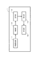
図1は、第1の実施の形態に係る基板処理装置1の全体構成を示すブロック図である。基板処理装置1は、情報取得部11と、判断部12と、塗布部13と、硬化部14と、除去部15とから構成される。
First Embodiment
FIG. 1 is a block diagram showing the overall configuration of a substrate processing apparatus 1 according to the first embodiment. The substrate processing apparatus 1 includes an
なお、図1に示す基板処理装置1においては、本願発明における実施形態を説明するために必要な構成のみを抜き出して示している。従って例えば、パーティクル除去対象表面を備える基板は、ベルトコンベアや搬送ロボット等の搬送装置によって搬送される。当該搬送装置については基板処理装置1に備えられているものの、図1においてはその図示を省略している。また例えば、各部の働きを制御する制御部も設けられているが同様に図示していない。 In addition, in the substrate processing apparatus 1 shown in FIG. 1, only the structure required in order to describe embodiment in this invention is extracted and shown. Therefore, for example, the substrate provided with the particle removal target surface is transported by a transport device such as a belt conveyor or a transport robot. Although the said transfer apparatus is equipped with the substrate processing apparatus 1, the illustration is abbreviate | omitted in FIG. For example, although the control part which controls the operation of each part is also provided, it is not illustrated similarly.
基板処理装置1に関して図1に示す上記各部の詳細な機能、働きについては、以下において基板処理方法を説明する際に適宜併せて説明する。また、基板処理方法については、その方法ごとに説明を行う。 The detailed functions and functions of the above-described units shown in FIG. 1 with respect to the substrate processing apparatus 1 will be described as appropriate in the following description of the substrate processing method. The substrate processing method will be described for each of the methods.
まず、パーティクルのパーティクル除去対象表面からの除去の流れについて、その基本となる基板処理方法について説明する。図2は、実施の形態に係るパーティクルの除去の流れを示すフローチャートである。そしてここでは、基本となる基板処理方法として特にステップST1ないしステップST11までの流れを説明する。また説明に当たっては、適宜図3、及び図4ないし図8を利用する。 First, the flow of removal of particles from the particle removal target surface will be described with reference to the substrate processing method as a basis. FIG. 2 is a flowchart showing the flow of particle removal according to the embodiment. Here, the flow from step ST1 to step ST11 will be particularly described as the basic substrate processing method. Also, in the description, FIGS. 3 and 4 to 8 will be used as appropriate.
図3は、実施の形態に係るパーティクル除去対象表面に存在するパーティクルを示す模式図である。図3に示すように、パーティクルPは、パーティクル除去対象表面B1に付着している。このようなパーティクルPがパーティクル除去対象表面B1に付着していると、上述したように、例えば、パターン欠陥の発生等、今後の基板処理に様々な不都合を招来することになるため、除去する必要がある。 FIG. 3 is a schematic view showing particles present on the particle removal target surface according to the embodiment. As shown in FIG. 3, the particle P adheres to the particle removal target surface B1. If such particles P are attached to the particle removal target surface B1, as described above, for example, the occurrence of pattern defects and the like will cause various inconveniences in the future substrate processing, so it is necessary to remove There is.
なおここでの「パーティクルP」としては、例えば、基板に付着したレジスト、接着剤残渣等の有機物や、基板上に形成されていた膜の一部が該当する。 Here, as the “particles P”, for example, a resist attached to the substrate, an organic substance such as an adhesive residue, or a part of the film formed on the substrate corresponds.
また、ここでは、パーティクル除去対象表面B1の全面を洗浄等することによってパーティクルPを除去するのではなく、個々のパーティクルPを個別に除去することによって、最終的にパーティクル除去対象表面B1からパーティクルPの存在をなくすこととしている。 Furthermore, here, instead of removing the particles P by cleaning the entire surface of the particle removal target surface B1, the individual particles P are individually removed, and finally the particles P are removed from the particle removal target surface B1. It is decided to eliminate the existence of
ところで、「パーティクル除去対象表面」とは、いわゆる基板の表面のことである。またここでの「基板」としては、例えば、ウェーハ、マスク用基板、或いは、液晶基板といった様々な基板が考えられ、特に限定するものではない。そこで以下においては、パーティクルPが存在する板状の被処理物を便宜上適宜「基板B」とし、その表面を「パーティクル除去対象表面B1」と表わす。また、当該「パーティクル除去対象表面B1」は平らな状態であっても、何らかのパターンが形成されていても良く、その別は問わない。 By the way, the "particle removal target surface" is a so-called surface of a substrate. Further, as the “substrate” here, various substrates such as a wafer, a substrate for a mask, or a liquid crystal substrate can be considered, and it is not particularly limited. Therefore, in the following, a plate-shaped object to be treated in which particles P are present is referred to as “substrate B” for convenience, and the surface thereof is referred to as “particle removal target surface B1”. In addition, the “particle removal target surface B1” may be flat or may have a pattern formed thereon, and it does not matter.
図3では、基板Bを上方から俯瞰して見た状態を示しており、パーティクル除去対象表面B1上に3つのパーティクルPが存在している。このように、本発明の実施の形態においては、個々のパーティクルPを個別に除去することが可能な場合を挙げてパーティクルの除去の流れを説明するものである。 FIG. 3 shows a state in which the substrate B is viewed from above, and three particles P are present on the particle removal target surface B1. As described above, in the embodiment of the present invention, the flow of particle removal will be described by giving a case where individual particles P can be removed individually.
なお、図3においては、パーティクル除去対象表面B1に3つのパーティクルPが描かれているが、当然のことながら、基板Bの全面を何らかの方法で洗浄することによりパーティクルPの除去を行う必要がない状態であれば、パーティクルPの数については問わない。 Although three particles P are drawn on the particle removal target surface B1 in FIG. 3, it is needless to say that it is not necessary to remove the particles P by cleaning the entire surface of the substrate B by any method. As long as it is in the state, the number of particles P does not matter.
次に、図3に示すような、パーティクル除去対象表面B1上のパーティクルPを除去する流れについて、図2に示すフローチャートを用いて説明する。まず、基板処理装置1においては、パーティクルPの除去を行うに当たって、基板B上、すなわち、パーティクル除去対象表面B1のいずれの位置に除去の対象となるパーティクルPが存在しているか、その位置情報を取得する(ST1)。 Next, the flow for removing the particles P on the particle removal target surface B1 as shown in FIG. 3 will be described using the flowchart shown in FIG. First, in the substrate processing apparatus 1, when the particles P are to be removed, position information on the position on the substrate B, that is, on which position of the particle removal target surface B1 the particles P to be removed exist is provided. Acquire (ST1).
除去対象となるパーティクルPの位置情報は、例えば、基板処理装置1の外に設けられたカメラ等を利用した画像処理によって把握することができる。また位置情報の把握は、図1において図示しない、例えば位置把握装置によって行われる。従って、パーティクルPの位置情報については、除去処理を行うために基板処理装置1に基板Bが搬送されてくる際に併せて位置把握装置から基板処理装置1へと送信されてくる。 The position information of the particles P to be removed can be grasped, for example, by image processing using a camera or the like provided outside the substrate processing apparatus 1. Further, grasping of the position information is performed by, for example, a position grasping device not shown in FIG. Therefore, the position information of the particles P is transmitted from the position grasping device to the substrate processing apparatus 1 when the substrate B is transported to the substrate processing apparatus 1 for the removal processing.
このように本発明の実施の形態においては、基板処理装置1以外の装置においてパーティクルPの位置情報の把握を行うこととしているが、例えば、基板処理装置1自体がその機構を備えていても構わない。 As described above, in the embodiment of the present invention, the apparatus other than the substrate processing apparatus 1 determines the position information of the particles P. However, for example, the substrate processing apparatus 1 itself may have the mechanism. Absent.
基板処理装置1においては、情報取得部11において、送信されてきた除去の対象となるパーティクルPの位置情報を把握する。本発明の実施の形態においては、基板Bの全面を洗浄することでパーティクルPの除去を行う場合と異なって、個々のパーティクルPを個別に除去することから、除去の対象となるパーティクルPの位置情報の把握は非常に重要である。
In the substrate processing apparatus 1, the
情報取得部11において取得された、除去の対象となるパーティクルPの位置情報は、判断部12へと送られる。判断部12では、パーティクル除去対象表面B1に所定の面積以上の領域に固まってパーティクルPが存在しているか否か確認する(ST2)。
The position information of the particle P to be removed, which is acquired by the
例えば、図3に示すように、パーティクル除去対象表面B1上にそれぞれ別個にパーティクルPが存在している場合には、個別に除去することが可能であり、効率的である。 For example, as shown in FIG. 3, when the particles P exist separately on the particle removal target surface B1, they can be removed individually and are efficient.
一方、図示しないが、例えば、パーティクル除去対象表面B1上において線状にパーティクルPが存在している場合、或いは、ある領域にまとまりをもって存在している場合も考えられる。例えば、マスク基板に、接着剤によってベリクルを接着していた場合は、ベリクルの枠に沿ってマスク基板表面に線状の接着剤の跡(残渣)が残る。この場合は、基板Bの全面を洗浄するまでもないが、できるだけまとめてパーティクルPを除去できれば、例えば、タクトタイムの短縮に資することになる。 On the other hand, although not shown, it is also conceivable that, for example, the particles P are present linearly on the particle removal target surface B1 or are present in a certain area in a lump. For example, if the mask substrate is bonded with a pellicle by an adhesive, linear adhesive traces (residues) remain on the surface of the mask substrate along the frame of the velicle. In this case, although it is not necessary to clean the entire surface of the substrate B, if the particles P can be removed as collectively as possible, for example, it will contribute to shortening the tact time.
そこで、ここでは判断部12が、個々のパーティクルPを個別に除去するか、或いは、まとめて除去可能であるかを、パーティクルPのまとまり具合を基に判断する。すなわち、パーティクル除去対象表面B1上のパーティクルPの分布を基に判断する。なお、パーティクルPをまとめて除去する方法については、後述する。
Therefore, here, the
判断部12が情報取得部11からのパーティクルPの位置情報を基に判断した結果、パーティクルPはパーティクル除去対象表面B1上にてまとまりなくばらばらな状態で存在していると判断した場合には(ST2のNO)、パーティクルPを個別に除去することとする(ST3)。
As a result of judging by the
そこで判断部12は、パーティクルPの個別除去に向けて、さらに情報取得部11から除去の対象となるパーティクルPに関する情報や、パーティクル除去対象表面B1に関する情報を取得し、確認する(ST4)。ここで、パーティクルPに関する情報とは、例えば、パーティクルPの大きさ、形状、材質等である。また、パーティクル除去対象表面B1に関する情報とは、パーティクル除去対象表面B1の状態や基板Bの材質等の情報である。これらの情報は、どのような樹脂を使用してパーティクルPを絡め取っていくのかを判断する上で必要な情報である。
Therefore, the
判断部12がこれらの情報を基に、どのようにパーティクルPの除去処理を行うかを判断する。この判断は、例えば、図1の基板処理装置1の全体構成には示されていない記憶部に記憶されている、例えば、パーティクルPや基板Bの材質に適した樹脂のリストが記憶部に予め記憶されており、当該リストを基に行われても良い。或いは、基板処理装置1の操作者に問い合わせを行い、操作者の指示に基づいて判断しても良い。
Based on these pieces of information, the
この判断の中に、除去補完物の利用の有無に関する判断(ST5)も含まれる。ここで「除去補完物」とは、パーティクルPの除去処理を行う際に除去を容易、かつ、確実に行うために利用する物であり、例えば樹脂Rとの接着性が高い塩化ビニールの板や、樹脂Rとの接着性が高い材料を表面に塗布した金属板である。 This determination includes the determination (ST5) as to whether or not the removal complement is used. Here, the “removal complement” is a substance used to easily and reliably remove the particles P when removing the particles P. For example, a plate of polyvinyl chloride having high adhesiveness with the resin R or the like And a metal plate having a surface coated with a material having high adhesion to the resin R.
すなわち、後述するように、パーティクルPの除去に当たっては、パーティクルPに樹脂Rを塗布して硬化させ、硬化したパーティクルPを含む樹脂Rを除去部が除去することになる。但し、除去部15が硬化した樹脂を把持する機構をもって構成されている場合、例えば、塗布した樹脂Rがパーティクル除去対象表面B1上にて薄く広がった状態で硬化してしまうと、当該樹脂Rを把持することが困難となる。
That is, as described later, when removing the particles P, the resin R is applied to the particles P and cured, and the removing portion removes the resin R including the cured particles P. However, if the removing
このような場合に、除去補完物を利用すれば、樹脂Rを硬化させたときに、パーティクルPと除去補完物が硬化した樹脂Rと一体化する。この後、除去部15が当該除去補完物を把持することで、結果的に樹脂R及びパーティクルPを把持、除去することが可能となる。そこで判断部12は、当該除去補完物を利用するか否かの判断を行う。なお、除去補完物を利用したパーティクルPの除去の方法については、後述する。
In such a case, when the removal complement is used, when the resin R is cured, the particle P and the removal supplement are integrated with the cured resin R. Thereafter, the
判断部12が判断した結果、除去補完物が不要である場合には(ST5のNO)、パーティクルPを除去する際に用いる樹脂Rを選択する(ST6)とともに、除去の対象となるパーティクルPの情報に基づいて、樹脂Rの塗布量、塗布範囲を確認する(ST7)。
As a result of the judgment by the
なお、樹脂Rが予め選択されている場合は、ステップST6を省略し、塗布量、塗布範囲を確認すれば良い。 When the resin R is selected in advance, step ST6 may be omitted, and the amount of application and the range of application may be confirmed.
図4ないし図8は、実施の形態に係るパーティクルPの除去の流れを示す工程図である。図4以下の工程図においては、パーティクル除去対象表面B1が上向きとなるように基板Bを水平に示している。従って、このように示されるパーティクル除去対象表面B1上のパーティクルPに対して、その上方から樹脂Rが塗布されて除去されることになる。 4 to 8 are process diagrams showing the flow of removal of the particles P according to the embodiment. In the process drawings of FIG. 4 and the following figures, the substrate B is shown horizontally so that the particle removal target surface B1 is directed upward. Therefore, the resin R is applied and removed from above the particles P on the particle removal target surface B1 shown in this way.
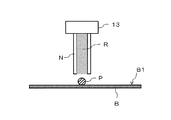
図4においては、パーティクルPの上方に樹脂Rを塗布する塗布部13が示されている。塗布部13としては、例えば、インクジェットの吐出機構を利用することができる。塗布部13を構成するノズルNは、パーティクルPの位置情報に基づき、パーティクルPを挟んでパーティクル除去対象表面B1に対向する位置に配置される。ノズルN内には、パーティクルPに対して塗布する樹脂Rが充填されており、基板処理装置1の指示に基づき、樹脂RがパーティクルPに向けて塗布される(ST8)。
In FIG. 4, the
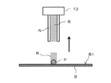
図5は、パーティクルPに対して樹脂Rが塗布された状態を示している。併せて図5においては、塗布された樹脂Rに対して横方向からの矢印が示されている。これは、硬化部14による、パーティクルPを包み込むように塗布された樹脂Rを硬化させる処理を示したものである。
FIG. 5 shows a state in which the resin R is applied to the particles P. In addition, in FIG. 5, an arrow from the lateral direction to the applied resin R is shown. This shows a process of curing the resin R applied so as to wrap the particles P by the curing
樹脂Rとしては、例えば、紫外線を照射することによって硬化する紫外線硬化樹脂を選択することや、或いは、加熱することで硬化する熱硬化性樹脂を選択することも可能である。上述したように、除去の対象となるパーティクルPと当該パーティクルPが存在するパーティクル除去対象表面B1の性質に合わせて樹脂Rが選択される。 As the resin R, for example, it is possible to select an ultraviolet curable resin which is cured by irradiating ultraviolet light, or to select a thermosetting resin which is cured by heating. As described above, the resin R is selected in accordance with the properties of the particle P to be removed and the particle removal target surface B1 in which the particle P is present.
従って、もし紫外線硬化樹脂が樹脂Rとして選択された場合には、図5において示される矢印は光源から照射される紫外線を表わす。また、樹脂Rとして熱硬化性樹脂が選択された場合には、図5に示す矢印は熱源から照射される熱を表わす。 Thus, if an ultraviolet curable resin is selected as resin R, the arrows shown in FIG. 5 represent the ultraviolet light emitted from the light source. Also, when a thermosetting resin is selected as the resin R, the arrows shown in FIG. 5 represent the heat radiated from the heat source.
このように、パーティクルPに対して塗布された樹脂Rに対して、選択された樹脂Rの性質に合わせた硬化部14が選択され、樹脂Rが硬化される(ST9)。樹脂Rは、パーティクルPを絡めるように塗布されていることから、硬化部14による硬化の工程を経ることによって、パーティクルPごと樹脂Rが硬化する。
As described above, with respect to the resin R applied to the particles P, the cured
図6は、硬化した樹脂R及びパーティクルPを示すものである。塗布部13はパーティクルPに対する樹脂Rの塗布処理を終了し、硬化処理も終了した後、図6に示される矢印の向きに、すなわち、上方に移動する。これは、次の工程である除去部15による樹脂R及びパーティクルPの除去が円滑に行われるようにするために、対象となるパーティクルPの上方から退くものである。
FIG. 6 shows the cured resin R and the particles P. The
なお、ここでは、硬化部14による樹脂Rの硬化処理が終了してから塗布部13が移動を開始しているが、硬化部14による硬化処理と同時に塗布部13が移動するように制御されても良い。
Here, the
また、樹脂Rは既に硬化部14による硬化の工程が終了したことから、パーティクル除去対象表面B1上にパーティクルPを含めて存在している。特に図6においては、硬化した樹脂Rが柱体の形で示されているが、硬化後の樹脂Rの形状はこの示されている形状に限られるものではない。また、塗布部13を構成するノズルNは、硬化部14による硬化の工程中にノズルN内の樹脂Rが硬化してしまうことを避けるために、ノズルNは、例えば、紫外線を透過しない金属等の材質で形成されている。
Further, since the resin R has already been cured by the curing
図7は、除去部15がパーティクルPを除去するために、硬化した樹脂Rを把持している状態を示している(ST10)。除去部15は、硬化された樹脂Rを除去することによって、樹脂Rに絡まって同様に硬化しているパーティクルPを除去するものである。
FIG. 7 shows a state in which the removing
除去部15は、ここでは、硬化した樹脂R(パーティクルP)を把持し、持ち上げるクレーンとして構成されている。また除去部15の構成については、説明の都合上、図7に示すようなクレーンを例に挙げているが、例えば、樹脂Rを把持する機構については、図7に示されている機構に限定されるものではない。例えば、「把持」とは掴む機構に限られず、除去部15は、そのパーティクルPに対向する面に、減圧部に接続された孔を有し、空気を吸引することによって樹脂R(パーティクルP)を吸引保持する機構も考えられる。
Here, the removing
すなわち、除去部15によって個々のパーティクルPを個別に除去し易くするために、パーティクルPを樹脂Rにて硬化させているとも言いうる。このように樹脂Rを利用してパーティクルPを硬化することで、パーティクルPのみを何の処理も行わず個別に除去するよりも容易に、かつ、確実に除去することができる。
That is, it can be said that the particles P are cured with the resin R in order to facilitate removal of the individual particles P individually by the removing
図8は、除去部15が把持した樹脂RをパーティクルPごと、矢印に示すように上方に持ち上げた状態を示している。除去部15が樹脂RとパーティクルPとをまとめて引き上げて、廃棄場所とされる位置まで移動し、樹脂Rを離間することによって、パーティクル除去対象表面B1上のパーティクルPが廃棄される。除去部15が樹脂Rを離間する機構は、例えば、除去部15はパーティクルPに対向する面に、加圧部に接続された孔を有し、空気を放出することによって樹脂R(パーティクルP)を離間する機構が考えられる。
FIG. 8 shows a state in which the resin R held by the removing
以上で、1つのパーティクルPの除去が終了したことになる(ST11)。 Thus, the removal of one particle P is completed (ST11).
但し、上述したパーティクルPの除去の工程は、パーティクル除去対象表面B1上に除去の対象となるパーティクルPが存在する限り繰り返し行われる。 However, the process of removing the particles P described above is repeated as long as the particles P to be removed are present on the particle removal target surface B1.
判断部12は、除去部15がパーティクルPを樹脂Rごと廃棄した後、パーティクルPの位置情報を基に、さらにパーティクル除去対象表面B1上に除去すべきパーティクルPが存在するか否か確認する(ST12)。その結果、パーティクルPが存在する場合には(ST12のYES)、ステップST4に戻って、再度上述した処理工程を繰り返してパーティクルPを除去する。一方、判断の結果、パーティクルPがパーティクル除去対象表面B1上に存在しないことが確認された場合には(ST12のNO)、パーティクルPの除去工程は完了する。
After the
以上でパーティクル除去対象表面B1上のパーティクルPを除去するための基本的な流れを説明した。次に、上述した、除去補完物Eを利用したパーティクルPの除去の方法について、図2に示すフローチャート及び適宜図9ないし図13を利用して説明する。図9ないし図13は、第1の実施の形態に係るパーティクルPの除去の別の流れを示す工程図である。 The basic flow for removing the particles P on the particle removal target surface B1 has been described above. Next, the method of removing the particles P using the removal complement E described above will be described using the flowchart shown in FIG. 2 and, as appropriate, FIG. 9 to FIG. FIG. 9 to FIG. 13 are process diagrams showing another flow of removal of the particles P according to the first embodiment.
図2のフローチャートに示すように、除去補完物Eの利用が必要であるか否か、判断部12が判断した結果、パーティクルPの状態やパーティクル除去対象表面B1の状態から除去補完物Eの利用が必要となった場合には(ST5のYES)、まず、除去補完物Eの利用を前提とした樹脂Rの選択が行われる(ST21)。また、併せて樹脂Rの塗布量、塗布の範囲も確認される(ST22)。
As shown in the flowchart of FIG. 2, as a result of the
ここで、以下説明する除去補完物Eを利用したパーティクルPの除去の処理を行うに当たっては、判断部12は、硬化後の樹脂Rに対してパーティクル除去対象表面B1の方が除去補完物Eよりも剥がれやすい性質を備える樹脂Rを選択する必要がある。
Here, when performing processing for removing particles P using removal complement E, which will be described below, the
なぜならば、樹脂Rのパーティクル除去対象表面B1に対する密着性の方が除去補完物Eに対する密着性よりも高いと、後述するように、樹脂Rを硬化させた後に除去補完物Eごと樹脂R及びパーティクルPをパーティクル除去対象表面B1から引き上げる際に、パーティクル除去対象表面B1から樹脂Rが剥がれず、結果としてパーティクルPの除去を行うことができなくなってしまうからである。 This is because if the adhesion of the resin R to the particle removal target surface B1 is higher than the adhesion to the removal complement E, the removal complement E together with the resin R and particles after curing the resin R as described later When P is pulled up from the particle removal target surface B1, the resin R does not peel off from the particle removal target surface B1, and as a result, the particle P can not be removed.
従って、上述したような性質を持つ樹脂Rを選択することによって、除去の際のパーティクル除去対象表面B1に対するダメージの抑制と樹脂R及びパーティクルPの剥離性を両立させることができる。 Therefore, by selecting the resin R having the above-described properties, it is possible to achieve both suppression of damage to the particle removal target surface B1 at the time of removal and releasability of the resin R and the particles P.
その上で、図9に示すように、除去部15が除去補完物Eを移動させてパーティクルPの上方からパーティクル除去対象表面B1に向けてパーティクルPにかぶせるように載置する(ST23)。上述したように、除去補完物Eの役割は、樹脂Rで硬化させても除去することが困難と思われるパーティクルPをより確実に除去するために介助を行うことにある。ここでは、パーティクルPを除去する際に、硬化された樹脂R及びパーティクルPを直接除去部15が除去するのではなく、除去部15が除去補完物Eを把持することでパーティクルPの除去を容易にするものである。
Then, as shown in FIG. 9, the
なお、ここでは除去補完物Eとして、板状の物を用いているが、除去補完物Eとしての役割を果たすことが可能である限り、その形状は板状に限定されない。また、パーティクルP上への除去補完物Eの載置は、ここでは樹脂Rが塗布される前であるが、除去補完物Eの載置のタイミングは、例えば、樹脂Rの塗布後、硬化前であっても良い。 In addition, although the plate-like thing is used as the removal complement E here, as long as it is possible to play a role as the removal supplement E, the shape is not limited to plate shape. Also, the placement of the removal complement E on the particle P is here before the resin R is applied, but the timing of placement of the removal complement E is, for example, after the application of the resin R and before curing It may be
図10は、載置された除去補完物Eとパーティクル除去対象表面B1との間に樹脂Rを塗布する処理を示している。すなわち、樹脂Rが塗布部13のノズルNからパーティクルPが存在する除去補完物Eとパーティクル除去対象表面B1との間に塗布される(ST24)。設定された塗布量が塗布されたら、次に、塗布された樹脂Rに対して硬化部14が紫外線を照射等して樹脂Rの硬化の処理を行う(ST25)。図11では、硬化部14による硬化の処理が矢印によって示されている。
FIG. 10 shows a process of applying the resin R between the placed removal complement E and the particle removal target surface B1. That is, the resin R is applied from the nozzle N of the
当該樹脂Rの硬化が完了すると、次に、図12に示すように除去部15が除去補完物Eを把持する(ST26)。その上で、把持された除去補完物Eを除去部15が上方に引き上げることで、併せて樹脂R及びパーティクルPもパーティクル除去対象表面B1から上方に向けて除去されることになる(ST27)。この状態を示したのが図13である。上方に引き上げられた、除去補完物E、樹脂R及びパーティクルPは、除去部15によって予め定められた領域へと運ばれ廃棄される。これによって、基板B(パーティクル除去対象表面B1)上のパーティクルPが除去されることになる。
When the curing of the resin R is completed, the removing
その上で、除去部15がパーティクルPを樹脂Rごと廃棄した後、判断部12が、パーティクルPの位置情報を基に、さらにパーティクル除去対象表面B1上に除去すべきパーティクルPが存在するか否か確認する(ST12)のは、上述した通りである。
Then, after the removing
次に、ディスペンサFを使用したパーティクルPの除去の流れについて説明する。図14、図15は、第1の実施の形態に係るディスペンサFを使用したパーティクルPの除去の流れを示すフローチャートである。また、図16ないし図18は、第1の実施の形態に係るディスペンサFを使用したパーティクルPの除去の流れを示す工程図である。 Next, the flow of removal of particles P using the dispenser F will be described. 14 and 15 are flowcharts showing the flow of removal of particles P using the dispenser F according to the first embodiment. 16 to 18 are process diagrams showing the flow of removal of particles P using the dispenser F according to the first embodiment.
まず、樹脂RをパーティクルPに対して塗布する塗布部13Aに、ディスペンサFを装着する(ST31)。ここで「ディスペンサF」とは、上述したノズルNと同様、樹脂RをパーティクルPに対して塗布する役割を果たす部材である。そのため、ディスペンサFはその一端部が、パーティクルPに対して樹脂Rを塗布するべく塗布部13Aに装着される。なお、塗布部13AへのディスペンサFの装着方法については、既知の技術を利用することができる。
First, the dispenser F is attached to the
一方、当該ディスペンサFは、塗布部13Aとの間の装着関係を解消し、塗布部13Aから一端部を切り離すことによって、ディスペンサFを除去することができる。すなわち、塗布部13AとディスペンサFとは、脱着可能に接続される。
On the other hand, the dispenser F can remove the dispenser F by releasing the mounting relationship with the
塗布部13AとディスペンサFとは、このように脱着可能とされているので、例えば、ディスペンサFがパーティクルP及び樹脂Rをパーティクル除去対象表面B2からまとめて引き上げることができれば、その後、ディスペンサFを塗布部13Aから切り離してディスペンサFごとパーティクルPを除去(廃棄)することができる。このような処理が可能となれば、ディスペンサFを、例えば、使い捨てとすることも可能となる。
Since the
そのためには、パーティクルPに対して塗布した樹脂Rを硬化させる際、ディスペンサF内に保持されている樹脂Rまでも併せて硬化させることができれば、ディスペンサFごとパーティクルP及びパーティクルPに絡む樹脂Rを引き上げることが可能となる。 For that purpose, when curing the resin R applied to the particles P, it is possible to also cure the resin R held in the dispenser F together, the dispenser R together with the particles P and the resin R entangled in the particles P It is possible to pull up
そこで、本発明の実施の形態においては、パーティクルPに絡む樹脂Rを硬化させる際、ディスペンサF内に保持されている樹脂Rまでも併せて硬化させることとしている。そのために、ディスペンサFは、硬化部14が行う硬化処理において使用される、例えば、紫外線を透過する材質で形成されている。
Therefore, in the embodiment of the present invention, when the resin R entangled in the particles P is cured, the resin R held in the dispenser F is also cured. For this purpose, the dispenser F is formed of, for example, a material that transmits ultraviolet light, which is used in the curing process performed by the curing
上述した塗布部13におけるノズルNは、硬化部14が行う硬化処理によって内部に保持する樹脂Rまでもが硬化しないように、例えば、金属といった紫外線を透過しない材質で形成されていた。一方、ここでのディスペンサFは、パーティクルPに対して樹脂Rを塗布するだけではなく、硬化処理において、パーティクルPに絡む樹脂Rのみならず、ディスペンサF内に保持する樹脂Rをも硬化させる必要があることから、紫外線を透過する材質でディスペンサFを形成する。
The nozzle N in the
なお、樹脂Rが熱硬化性樹脂である場合には、熱伝導に優れる材質を採用することで、上述したように、硬化処理において、パーティクルPに絡む樹脂Rのみならず、ディスペンサF内に保持する樹脂Rをも硬化させることが可能となる。 In the case where the resin R is a thermosetting resin, by adopting a material excellent in heat conduction, as described above, in the curing process, the resin R is held not only in the resin P but also in the dispenser F. It is possible to cure the resin R to be cured.
上述したように、ディスペンサFの一端部は、塗布部13Aに装着が可能な形状とされている。一方、ディスペンサFの他端部は、吐出口が形成され、当該吐出口からパーティクルPに向けて樹脂Rが吐出される。また、この他端部には、当該吐出口の外部にパーティクル除去対象表面B2に対して対向する面F1が設けられている。
As described above, one end of the dispenser F is shaped to be attachable to the
このような面F1が設けられているのは、ディスペンサFを利用したパーティクルPの除去処理においては、ディスペンサF内の樹脂Rをも硬化させてパーティクルPに絡む樹脂Rごと引き上げて除去することになるためである。従って、ディスペンサFからパーティクルPに向けて塗布された樹脂Rが硬化される際に、パーティクルPからディスペンサFの内部までに存在することになる当該樹脂Rが硬化によって一体化することになる。このような状態になるからこそ、ディスペンサFを引き上げることで、パーティクルP及び樹脂Rが一体的に引き上げられることになる。 Such surface F1 is provided because, in the removal process of the particles P using the dispenser F, the resin R in the dispenser F is also cured and pulled up and removed together with the resin R entangled in the particles P. In order to Therefore, when the resin R applied from the dispenser F toward the particles P is cured, the resin R which is to be present from the particles P to the inside of the dispenser F is integrated by curing. Only in such a state, by pulling up the dispenser F, the particles P and the resin R can be pulled up integrally.
従って、ディスペンサFの引き上げに伴って、パーティクルP及び樹脂Rを一体的に引き上げるためには、硬化された樹脂Rについて相応の強度が求められることになる。この場合に、上述したように、ディスペンサFの他端部において、吐出口の外部にパーティクル除去対象表面B2に対して対向する面F1が設けられると、当該面F1に対する樹脂Rの接触面積が大きくなり、硬化した際に、より一体的に引き上げるための強度が増すことになる。そのため、当該面F1を他端部である吐出口の外部に形成するとともに、パーティクルPに対する樹脂Rの塗布を行う際には、当該面F1に対して樹脂Rが接触するだけの十分な量を塗布することとしている。 Therefore, in order to pull up the particles P and the resin R integrally as the dispenser F is pulled up, a corresponding strength is required for the cured resin R. In this case, as described above, when the surface F1 facing the particle removal target surface B2 is provided outside the discharge port at the other end of the dispenser F, the contact area of the resin R with the surface F1 is large. When cured, the strength for pulling up more integrally will be increased. Therefore, when the surface F1 is formed outside the discharge port, which is the other end, and the resin R is applied to the particles P, a sufficient amount of resin R to be in contact with the surface F1 It is supposed to apply.
なお、この面F1の形状については、吐出口の外部であれば、例えば、吐出口の全周にわたって設けられていても良い。また、全周にわたって設けられる際に、パーティクル除去対象表面B2への対向面の形状が、円形、多角形等、どのような形状であっても構わない。 The shape of the surface F1 may be provided, for example, over the entire circumference of the discharge port as long as it is outside the discharge port. In addition, when provided over the entire circumference, the shape of the surface facing the particle removal target surface B2 may be any shape such as a circle or a polygon.
ディスペンサFを使用したパーティクルPの除去の流れについては、塗布部13AにディスペンサFを装着した後、実際にパーティクルPに対して樹脂Rを塗布するための準備に入る。
Regarding the flow of removal of the particles P using the dispenser F, after the dispenser F is attached to the
すなわち、これまで説明した通り、基板処理装置1においてパーティクル除去対象表面B2のいずれの位置に除去の対象となるパーティクルPが存在しているか、その位置情報を把握する(ST32)。 That is, as described above, in the substrate processing apparatus 1, the position information is grasped at which position of the particle removal target surface B2 the particle P to be removed exists (ST32).
情報取得部11において取得された、除去の対象となるパーティクルPの位置情報は、判断部12へと送られる。判断部12では、パーティクル除去対象表面B2に所定の面積以上の領域に固まってパーティクルPが存在しているか否か確認する(ST33)。なお、パーティクルPをまとめて除去する方法については、後述する。
The position information of the particle P to be removed, which is acquired by the
判断部12が情報取得部11からのパーティクルPの位置情報を基に判断した結果、パーティクルPはパーティクル除去対象表面B2上にてまとまりなくばらばらな状態で存在していると判断した場合には(ST33のNO)、パーティクルPを個別に除去することとする(ST34)。
As a result of the determination by the
判断部12は、さらに、情報取得部11から除去の対象となるパーティクルPに関する情報や、パーティクル除去対象表面B2に関する情報を取得し、確認する(ST35)。判断部12は、これらパーティクルPに関する情報、パーティクル除去対象表面B2に関する情報の情報を基に、どのようにパーティクルPの除去処理を行うかを判断する。
The
その上で判断部12はさらに、パーティクルPを除去する際に用いる樹脂Rを選択する(ST36)とともに、除去の対象となるパーティクルPの情報に基づいて、樹脂Rの塗布量、塗布範囲を確認する(ST37)。
Then, the
基板処理装置1は、上述した各確認が完了したら、ディスペンサFを介して除去の対象となるパーティクルPに対して樹脂Rを塗布する(ST38)。 When the above-described respective confirmations are completed, the substrate processing apparatus 1 applies the resin R to the particles P to be removed through the dispenser F (ST38).
図16は、実施の形態に係るディスペンサFを使用したパーティクルPの除去の流れを示す工程図である。当該図16では、パーティクルPに対して樹脂Rを塗布する直前の状態が示されている。すなわち、塗布部13AにディスペンサFが装着されているとともに、当該ディスペンサFの内部には、樹脂Rが保持されている。一方、ディスペンサF及び樹脂Rの直下には、除去の対象となるパーティクルPが存在している。
FIG. 16 is a process diagram showing a flow of removal of particles P using the dispenser F according to the embodiment. In the said FIG. 16, the state in front of apply | coating resin R with respect to the particle P is shown. That is, the dispenser F is attached to the
図16ないし図18においては、これまで説明のために利用してきた工程図とは異なり、基板Bのパーティクル除去対象表面B2上にパターンが形成されている。そして、このパターンによって形作られる凹部に除去すべきパーティクルPが存在している。なお、ここで説明するディスペンサFを使用したパーティクルPの除去の流れにおいても、これまで利用してきた工程図に示されている、平坦なパーティクル除去対象表面B1上にパーティクルPが存在していても良い。 In FIGS. 16 to 18, a pattern is formed on the particle removal target surface B2 of the substrate B, unlike the process drawings used for the description so far. And the particle P which should be removed exists in the recessed part formed by this pattern. Also in the flow of removal of particles P using the dispenser F described here, even if the particles P are present on the flat particle removal target surface B1 shown in the process chart used so far, good.
図17では、上述したステップST38の状態、すなわち、パーティクルPに対して樹脂RがディスペンサFを介して塗布された状態が示されている。ディスペンサFの他端部の吐出口から樹脂Rが吐出される。 FIG. 17 shows the state of step ST38 described above, that is, the state in which the resin R is applied to the particles P via the dispenser F. The resin R is discharged from the discharge port at the other end of the dispenser F.
ここでは、パターン内に存在するパーティクルPに対して十分に樹脂Rが絡み、パターン内が樹脂Rで充填されている。また、パターン内から上方、ディスペンサFの内部に保持されている樹脂Rまで樹脂Rが連続するように、パターンを形成する溝の上、及び、面F1に接触するように樹脂Rが塗布されている。 Here, the resin R is sufficiently entangled with the particles P present in the pattern, and the inside of the pattern is filled with the resin R. In addition, the resin R is applied so that the resin R is continuous from the inside of the pattern to the resin R held inside the dispenser F so as to be in contact with the upper surface of the groove forming the pattern and the surface F1. There is.
このような状態の下、硬化部14が当該樹脂Rに対して例えば、紫外線を照射する。ディスペンサFは、上述したように、例えば、紫外線を透過する性質を持つ材質で形成されていることから、照射された紫外線がパーティクルPに絡む樹脂Rはもちろんのこと、ディスペンサFの内部に保持されている樹脂Rについても硬化させる。
Under such a condition, the curing
すなわち、図17に示されているように、パターンの溝の内部に存在するパーティクルPに絡む樹脂Rから、その上方、パターンを形成する溝の上部とディスペンサFの他端部に形成されている面F1との間、さらにその上の、樹脂Rが吐出されるディスペンサFの他端部から塗布部13Aに装着されている一端部までのディスペンサFの内部に保持されている樹脂Rまでが、紫外線の照射を受けて一体的に硬化する。
That is, as shown in FIG. 17, the resin R is formed on the upper portion of the groove forming the pattern and the other end of the dispenser F from the resin R entangled with the particles P present inside the groove of the pattern Between the surface F1 and the resin R held in the dispenser F from the other end of the dispenser F from which the resin R is discharged to the end thereof mounted on the
このように面F1に接触する樹脂Rも硬化するため、この状態から図18に示すように、塗布部13Aを上方に引き上げると、硬化した樹脂Rも一体的に上方へと引き上げられる(図15のST40)。パターンの溝の内部にも樹脂Rが充填されて硬化しているので、溝の内部に存在したパーティクルPも硬化された樹脂Rに絡め取られて上方へと引き上げられることになる。
Since the resin R in contact with the surface F1 is also cured in this manner, as shown in FIG. 18, when the
なお、このように特にパーティクル除去対象表面B2にパターンが形成されており、その凹部に除去の対象となるパーティクルPが存在する場合、当該凹部を樹脂Rで満たしてしまうと、今度は樹脂Rを硬化させた後の引き上げが困難となる場合が考えられる。すなわち、パーティクルPを含む凹部からディスペンサFの内部までに存在する樹脂Rが硬化することで一体的に引き上げることが可能となるが、樹脂Rが塗布されて凹部を満たしてしまうと、硬化させた場合に当該凹部の表面と樹脂Rとの密着性が高くなりすぎてしまい、硬化した樹脂Rを引き上げるのに大きな力が必要となってしまう。 When the pattern is formed on the particle removal target surface B2 in this way and the particles P to be removed are present in the recess, if the recess is filled with the resin R, then the resin R is removed. In some cases, it may be difficult to pull up after curing. That is, although it becomes possible to pull up integrally by hardening resin R which exists from the recessed part containing particle P to the inside of dispenser F, when resin R is applied and the recessed part is filled, it was hardened. In this case, the adhesion between the surface of the recess and the resin R becomes too high, and a large force is required to pull up the cured resin R.
このような場合に無理矢理引き上げると、例えば、引き上げの途中で硬化した樹脂Rが損壊しパーティクルPを引き上げることができなくなってしまったり、或いは、樹脂Rと凹部との高い密着性により引き上げに伴ってパターンまでもが引っ張られてしまうことも考えられなくはない。このような状況はパターン欠陥を招来しかねない。 In such a case, if it is forcedly pulled up, for example, the cured resin R may be broken in the middle of pulling up and the particle P can not be pulled up, or the high adhesion between the resin R and the recess causes the pulling up. It can not be imagined that even the pattern may be pulled. Such a situation can lead to pattern defects.
そこで、例えば、ここで説明しているように、パーティクル除去対象表面B2にパターンが形成されておりその凹部にパーティクルPが存在するような場合には、塗布後硬化させた場合に、塗布時の体積よりも硬化時の体積が減少する性質を備える樹脂Rを選択し使用すると、上述したような弊害を回避し得る。 Therefore, for example, as described herein, in the case where a pattern is formed on the particle removal target surface B2 and particles P are present in the concave portion, when applied and cured, the time of application is By selecting and using a resin R having a property that the volume at the time of curing decreases rather than the volume, the above-mentioned adverse effects can be avoided.
これまでの説明により、パーティクル除去対象表面B2からパーティクルPが除去されることになる。その上で、パーティクル除去対象表面B2から引き上げたパーティクルPを廃棄するべく、塗布部13Aは硬化した樹脂R(パーティクルP)を含むディスペンサFごと移動する(ST41)。ディスペンサFの一端部は、塗布部13Aに着脱可能に装着されていることから、塗布部13AがパーティクルPを廃棄する場所まで移動した後、ディスペンサFを塗布部13Aから切り離す。
As described above, the particle P is removed from the particle removal target surface B2. Then, in order to discard the particles P pulled up from the particle removal target surface B2, the
ディスペンサFを塗布部13Aから切り離すことに関して、ディスペンサFは塗布部13Aに対して、例えば、ネジ式によって装着されている。そのためこのようにディスペンサFが塗布部13に装着されている場合、ディスペンサFを図示しない脱着機構、または、手動でねじることで、塗布部13Aから切り離すことができる。
The dispenser F is attached to the
このような構成を採用することで、ディスペンサF及びパーティクルPを含んで硬化している樹脂Rをまとめて廃棄することができる。これでパーティクル除去対象表面B2からパーティクルPを除去することができる。 By adopting such a configuration, it is possible to collectively discard the cured resin R including the dispenser F and the particles P. Thus, the particles P can be removed from the particle removal target surface B2.
このようにディスペンサFは、硬化された樹脂Rごと塗布部13Aから切り離されて廃棄されるが、当該ディスペンサFから樹脂Rを取り除くことで再利用が可能である。そこで、基板処理装置1は、切り離されたディスペンサFを再利用するか否かを確認する(ST43)。
Thus, the dispenser F is separated from the
ディスペンサFを再利用する場合には(ST43のYES)、例えばディスペンサFを切り離し廃棄した場所で、或いは、別の場所にて洗浄を行って、樹脂R及びパーティクルPをディスペンサFから取り除く(ST44)。洗浄されたディスペンサFは、保管場所にて保管される(ST45)。ステップST31にて説明したように、ディスペンサFを用いたパーティクルPの除去処理が行われる際に、事前に塗布部13Aに装着されることになることから、改めて塗布部13Aに装着されるまで保管される。
When the dispenser F is to be reused (YES in ST43), for example, the resin R and the particles P are removed from the dispenser F by washing at a place where the dispenser F is separated and discarded or at another place (ST44) . The cleaned dispenser F is stored at the storage location (ST45). As described in step ST31, when the removal process of the particles P using the dispenser F is performed, the particles are attached to the
一方、ディスペンサFの再利用が行われない場合には(ST43のNO)、ディスペンサFはパーティクルP及び樹脂Rと一体化した状態で廃棄となる。 On the other hand, when the dispenser F is not reused (NO in ST43), the dispenser F is discarded in a state of being integrated with the particles P and the resin R.
その上で、判断部12は、未だパーティクル除去対象表面B2上に除去しなければならないパーティクルPが存在するか否か確認する(ST46)。パーティクルPが存在する場合には(ST46のYES)、再度ステップST35に戻って除去の対象となるパーティクルP等の情報を確認する。なお、ここではこのステップに戻ることとしているが、例えば、ディスペンサFを再度塗布部13Aに装着するステップまで戻って、改めてそこからパーティクルPの除去処理を開始しても良い。
Then, the
確認の結果、パーティクルPが存在しない場合には(ST46のNO)、これでディスペンサFを使用したパーティクルPの除去処理は終了する。 As a result of the confirmation, when the particle P does not exist (NO in ST46), the removal process of the particle P using the dispenser F is finished.
以上の構成、及び工程を採用することで、パーティクル除去対象表面に存在するパーティクルを、当該表面全面の洗浄により除去する必要性が低い場合に、個別に効率よく、かつ、簡易確実に除去することができる基板処理装置及び基板処理方法を提供することができる。 By adopting the above-described configuration and process, it is possible to remove the particles present on the particle removal target surface individually, efficiently and simply and reliably when it is less necessary to remove the particles by cleaning the entire surface. A substrate processing apparatus and a substrate processing method capable of
(第2の実施の形態)
次に本発明における第2の実施の形態について説明する。なお、第2の実施の形態において、上述の第1の実施の形態において説明した構成要素と同一の構成要素には同一の符号を付し、同一の構成要素の説明は重複するので省略する。
Second Embodiment
Next, a second embodiment of the present invention will be described. In the second embodiment, the same components as those described in the first embodiment are denoted by the same reference numerals, and the description of the same components will be omitted.
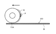
これまで説明した第1の実施の形態においては、パーティクルPを硬化させた樹脂Rとともに、除去部15を用いてパーティクル除去対象表面B1,B2から引き上げることでパーティクルPを除去していた。第2の実施の形態においては、除去部15Aとしてローラを採用し、当該ローラ(以下、適宜「ローラ15A」と表わす)を用いてパーティクルPを含む硬化された樹脂Rを除去する。
In the first embodiment described above, the particles P are removed by pulling up from the particle removal target surfaces B1 and B2 using the removing
図19は、第2の実施の形態に係る基板処理装置1Aの全体構成を示すブロック図である。基板処理装置1Aでは、除去部15Aとして、ローラ15Aを採用している。また、図20は、第2の実施の形態に係るローラ15Aを使用したパーティクルPの除去の流れを示すフローチャートである。以下、ローラ15Aを使用したパーティクルPの除去の方法について、適宜図21ないし図26も利用しつつ説明する。
FIG. 19 is a block diagram showing the overall configuration of a substrate processing apparatus 1A according to the second embodiment. In the substrate processing apparatus 1A, the
まず、前提として、基板処理装置1Aの情報取得部11は、パーティクル除去対象表面B3上において特定される、除去の対象となるパーティクルPの位置情報を把握する(図2のST1)。その上で、判断部12が、当該パーティクルPが所定の面積以上の領域に固まって存在しているか否かを判断する(ST2)。これは、例えば、パーティクル除去対象表面B3上において線状にパーティクルPが存在している場合、或いは、ある領域にまとまりをもって存在している場合に、できるだけまとめてパーティクルPを除去できれば、より効率的である、との考えに基づく。
First, as a premise, the
そこで、判断部12による判断が、個々のパーティクルPを個別に除去する場合(ST2のNO)については第1の実施の形態において説明した。第2の実施の形態においてはパーティクルPをまとめて除去する場合について説明する。
Therefore, the case where the determination by the
判断部12が、例えば、パーティクルPがある領域に固まって存在していると判断した場合には(ST2のYES)、パーティクルPをローラ15Aを使用して除去する(ST51)。
If the
そのため、判断部12はさらに、情報取得部11から除去の対象となるパーティクルPに関する情報や、パーティクル除去対象表面B3に関する情報を取得し、確認する(ST52)。判断部12は、これらパーティクルPに関する情報、パーティクル除去対象表面B3に関する情報の情報を基に、どのようにパーティクルPの除去処理を行うかを判断する。その上で判断部12はさらに、パーティクルPを除去する際に用いる樹脂Rを選択する(ST53)とともに、除去の対象となるパーティクルPの情報に基づいて、樹脂Rの塗布量、塗布範囲を確認する(ST54)。
Therefore, the
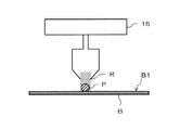
図21は、このように樹脂Rを塗布する前の確認を完了させた状態を示している。すなわち、塗布部13を除去対象とするパーティクルPの上方に移動させる。この状態で塗布部13のノズルN内には、塗布する樹脂Rが充填されている。また、ローラ15AもパーティクルPに対して樹脂Rが塗布され、硬化された後に当該パーティクルPを含む樹脂Rを除去するべく、用意されている。なお、ローラ15Aは、パーティクル除去対象表面B3に対して密着させると、例えば、パーティクル除去対象表面B3にパターンが形成されていた場合に当該パターンを壊してしまうことになる。そのため、ローラ15Aはパーティクル除去対象表面B3から数μm〜数100μm離間した状態にある。
FIG. 21 shows a state in which the confirmation before applying the resin R is completed. That is, the
次に図22に示すように、塗布部13のノズルNから樹脂RがパーティクルPに向けて吐出される(ST55)。そして、図23に示されているように、塗布部13がパーティクルPに向けて樹脂Rを塗布した後、塗布部13は、上方へと移動する。併せてローラ15Aも樹脂Rに向けて矢印の方向に移動を開始する(ST56)。
Next, as shown in FIG. 22, the resin R is discharged from the nozzle N of the
塗布された樹脂Rに対しては、例えば、硬化部14から紫外線が照射され、硬化される(ST57、図24参照)。この間もローラ15Aは、図24に示す矢印の方向に移動し、硬化した樹脂Rに向けて移動を続けている。
The applied resin R is, for example, irradiated with ultraviolet light from the curing
なお、硬化部14として紫外線照射を用いる場合、ローラ15Aは、紫外線が透過できるように、例えば、石英等の透過性の高い材料で形成される。よって、硬化部14は、ローラ15Aに遮られることなく、樹脂Rに紫外線を照射し続けることができる。
In addition, when using an ultraviolet irradiation as the hardening
ローラ15Aがこのまま矢印の方向に移動すると、パーティクルPを含んで硬化した樹脂Rと接触する。ここで塗布された樹脂Rは、パーティクル除去対象表面B3よりもローラ15Aの回転表面により密着する性質を備えている。または、ローラ15Aの表面に樹脂Rとの密着性が高い材料を予め塗布しておいても良い。
When the
そのため、ローラ15Aがパーティクル除去対象表面B3上を回転した場合、硬化した樹脂Rは、ローラ15Aの回転表面に密着する(ST58)。そのため図25に示すように、ローラ15Aが回転しつつ移動することで樹脂Rが回転表面に密着し、パーティクル除去対象表面B3から剥がれるように除去される。樹脂Rは、除去対象となるパーティクルPも絡めて硬化していることから、ローラ15Aの回転に伴ってその回転表面に密着する樹脂Rに従って、パーティクルPもパーティクル除去対象表面B3から剥がれる。
Therefore, when the
さらにローラ15Aが回転を続けることによって、図26に示すように、パーティクル除去対象表面B3上に存在していたパーティクルP及び樹脂Rは完全にパーティクル除去対象表面B3から剥がれてローラ15Aの表面に密着する。このようにして、パーティクルP及び樹脂Rがパーティクル除去対象表面B3から除去される(ST59)。
Further, as the
なお、このままではパーティクル除去対象表面B3からはパーティクルPが除去されるが、ローラ15Aには樹脂R及びパーティクルPが密着した状態である。そこで、ローラ15Aの表面に付着している樹脂R及びパーティクルPを図示しない洗浄機構において洗浄し、除去する(ST60)。
Although the particles P are removed from the particle removal target surface B3 as it is, the resin R and the particles P are in close contact with the
その上で、基板処理装置1Aの判断部12は、パーティクル除去対象表面B3上に未だ除去の対象となるパーティクルPが存在するか否かを確認し(ST61)、存在する場合には、再度ステップST52に戻って、パーティクルPの除去処理が行われる。
Then, the
一方、除去の対象となるパーティクルPはなく、パーティクル除去対象表面B3から全てのパーティクルPが除去され、パーティクルPの存在が確認できないと判断された場合には(ST61のNO)、ここでパーティクルPの除去処理は完了する。 On the other hand, there is no particle P to be removed, and all particles P are removed from the particle removal target surface B3, and it is determined that the presence of the particles P can not be confirmed (NO in ST61). Removal process is complete.
なお、ローラがパーティクル除去対象表面B3上を回転した場合において、硬化した樹脂Rをローラの回転表面に密着させる、または、除去する方法として、さらに以下の方法も採用することができる。 When the roller rotates on the particle removal target surface B3, the following method can also be adopted as a method for bringing the cured resin R into close contact with or removing the rotating surface of the roller.
図27、及び図28は、第2の実施の形態に係るローラ15Bを使用した別のパーティクルPの除去の流れを示す工程図である。ローラ15Bは、その表面にローラ15Bの回転中心まで貫通する孔21が設けられている。この孔21の数は、単数、或いは、複数であっても良い。また、孔21は、ローラ15Bの回転中心からその表面に向けてテーパ状となるように形成されていても良い。図27、或いは、図28では、説明の便宜上、孔21はテーパ状に形成されている。
FIGS. 27 and 28 are process diagrams showing the flow of removal of another particle P using the
さらに孔21は、ローラ15Bの回転中心に設けられている減圧部22、或いは、加圧部23に接続されている。
Furthermore, the
図27に示すように、ローラ15Bが矢印方向に回転してパーティクル除去対象表面B3上に存在するパーティクルPを除去する場合には、減圧部22が作動し、ローラ15Bの表面に設けられている孔21を介して空気を吸引することで、パーティクルPを絡めて硬化している樹脂Rをローラ15Bの表面に吸着させる(ST58)。このようにして、パーティクルP及び樹脂Rがパーティクル除去対象表面B3から除去される(ST59)。
As shown in FIG. 27, when the
なお、減圧部22における吸引の力については、樹脂Rとパーティクル除去対象表面B3との密着度合いによって適宜変更することができる。 The suction force in the pressure reducing section 22 can be appropriately changed according to the degree of adhesion between the resin R and the particle removal target surface B3.
また、樹脂Rをパーティクル除去対象表面B3から剥がしても減圧部22が空気を吸引し続けることによって、たとえ樹脂Rがローラ15Bの表面から剥がれそうになったとしても、樹脂Rをローラ15Bの表面に吸着した状態のままとすることができる。
Further, even if the resin R is peeled off the particle removal target surface B3, the decompression unit 22 continues to suck the air, so that even if the resin R is likely to be peeled off from the surface of the
その後、樹脂Rがパーティクル除去対象表面B3から完全に剥がれた後、図28に示すように、今度は加圧部23を動作させることによって、孔21を介して空気がローラ15Bの表面から放出される。ローラ15Bの表面には、パーティクル除去対象表面B3から剥がされたパーティクルPを含む樹脂Rが吸着されているが、加圧部23によって加圧された空気が孔21から放出されることによって、ローラ15Bから樹脂Rが剥がされ、除去されることになる(ST60)。
Thereafter, after the resin R completely separates from the particle removal target surface B3, as shown in FIG. 28, air is released from the surface of the
なおここでは、ローラ15Bの回転中心に減圧部22と加圧部23とを設けて、樹脂Rの吸引と引き剥がしを行うことを例に挙げて説明したが、一方のみを設けることも可能である。例えば、加圧部23のみを設けることもできる。この場合、樹脂Rをパーティクル除去対象表面B3に密着させる際には、樹脂R自身の吸着力を利用してローラ15Bの表面に密着させ、当該樹脂Rを剥がす際には、加圧部23を用いてローラ15Bから樹脂Rを除去することも考えられる。
Here, the pressure reducing portion 22 and the pressure portion 23 are provided at the rotation center of the
以上の構成、及び工程を採用することで、パーティクル除去対象表面に存在するパーティクルを、当該表面全面の洗浄により除去する必要性が低い場合に、個別に効率よく、かつ、簡易確実に除去することができる基板処理装置及び基板処理方法を提供することができる。 By adopting the above-described configuration and process, it is possible to remove the particles present on the particle removal target surface individually, efficiently and simply and reliably when it is less necessary to remove the particles by cleaning the entire surface. A substrate processing apparatus and a substrate processing method capable of
特にパーティクル除去対象表面に複数のパーティクルがある領域に固まって存在している場合に、これらのパーティクルを1つずつ個別に除去するのではなく、ローラを使用してある領域に存在するパーティクルをまとめて除去することが可能となる。従って、効率よく、また確実にパーティクルを除去することが可能となる。 In particular, in the case where a plurality of particles are present in a solid area on the particle removal target surface, these particles are not individually removed one by one, but the particles present in a certain area using rollers are summarized Can be removed. Therefore, it is possible to remove the particles efficiently and reliably.
なお、第2の実施の形態においては、ローラはパーティクルを含む硬化した樹脂を除去する、除去部の一態様として説明をした。但し、ローラは、樹脂(パーティクル)を除去する機能のみならず、例えば、樹脂を硬化する硬化部の機能を兼ね備えていても良い。例えば、ローラが回転する方向に向けて事前にローラから紫外線を照射することで、ローラに樹脂が密着してパーティクル共々除去される前に、樹脂を硬化させることができる。 In the second embodiment, the roller is described as one mode of the removing unit for removing the cured resin containing particles. However, the roller may have not only the function of removing the resin (particles) but also, for example, the function of a curing unit that cures the resin. For example, by irradiating ultraviolet light from the roller in the direction in which the roller rotates, the resin can be cured before the resin adheres to the roller and the particles are removed together.
或いは、ローラ内に加熱部を設けておき、ローラが樹脂と接触した場合、加熱されているローラが当該樹脂上を回転移動することで樹脂を硬化させるとともに、除去する構成としても良い。 Alternatively, a heating unit may be provided in the roller, and when the roller contacts the resin, the heated roller may rotate and move on the resin to harden and remove the resin.
ローラをこのように構成することで、硬化部を独立して設ける必要がなくなる。従って、基板処理装置の装置構成が簡略化され、設置コスト等を低減することが可能となる。また樹脂を硬化させた直後に除去することが可能となるため、処理時間の短縮化にも寄与する。 By configuring the roller in this manner, it is not necessary to provide the curing portion independently. Therefore, the apparatus configuration of the substrate processing apparatus can be simplified, and the installation cost and the like can be reduced. Moreover, since it becomes possible to remove immediately after hardening resin, it contributes also to shortening of processing time.
本発明の実施形態を説明したが、この実施形態は、例として提示したものであり、発明の範囲を限定することを意図していない。この実施形態は、その他の様々な形態で実施されることが可能であり、発明の要旨を逸脱しない範囲で、種々の省略、置き換え、変更を行うことができる。この実施形態やその変形は、発明の範囲や要旨に含まれると共に、特許請求の範囲に記載された発明とその均等の範囲に含まれる。 Although the embodiments of the present invention have been described, this embodiment is presented as an example and is not intended to limit the scope of the invention. This embodiment can be implemented in other various forms, and various omissions, replacements, and changes can be made without departing from the scope of the invention. This embodiment and its modifications are included in the scope and the gist of the invention, and are included in the invention described in the claims and the equivalents thereof.
例えば、パーティクルPに関する情報、パーティクル除去対象表面B1に関する情報を取得し、確認するステップ(図2のST4)、および情報取得部11は、予めこれらの情報が判明しているならば、省略することができる。その場合、パーティクルPの除去処理に使用する樹脂の種類や硬化部も予め決定したものを使用することができる。
For example, the step of acquiring and confirming the information on the particle P and the information on the particle removal target surface B1 (ST4 in FIG. 2) and the
また、例えば、除去補完物の要否を予め決定しておくこともできる。その場合、除去補完物を必要かどうか確認するステップ(図2のST5)を省略し、予め決定した判断に基づいてST6のステップ、またはST21のステップに進むことができる。 Also, for example, the necessity of the removal complement may be determined in advance. In that case, the step (ST5 in FIG. 2) for confirming whether or not the removal complement is necessary can be omitted, and the process can proceed to step ST6 or step ST21 based on a predetermined determination.
また、例えば、パーティクルPが所定の位置において所定の面積以上の領域に固まって存在していることが予め分かっていれば、図2のST2のステップを省略して、除去部としてローラ15Aを採用してもよい。この場合、判断部12を省略することができる。
In addition, for example, if it is known in advance that particles P are present in a predetermined area at a predetermined area or more, step ST2 in FIG. 2 is omitted, and
また、例えば、ディスペンサを再利用するか否かは処理開始前に予め決定しておくこともできる。その場合、図15のST43のステップで判断を分岐することなく、予め決定した判断に基づいてディスペンサの再利用または廃棄を行うことができる。 Also, for example, whether to reuse the dispenser can be determined in advance before the start of the process. In that case, the dispenser can be reused or discarded based on the predetermined determination without branching the determination in the step of ST43 of FIG.
また、例えば、図21では塗布部13を除去対象とするパーティクルPの上方に移動させる例を示したが、塗布部13を水平方向に移動させながら、樹脂を塗布するようにしてもよい。その場合、塗布部13が水平方向に移動しながらパーティクルの存在する領域に、連続的にあるいは間欠的に樹脂Rの塗布を行う。硬化部14は樹脂Rの塗布を開始した後に、上述した実施例に示した硬化を行うことによって樹脂Rを硬化させる。その後、ローラ15Aを回転させることによって樹脂を除去することができる。この場合、硬化部14、ローラ15Aは塗布部13の移動と、相対速度を制御しながら移動させることができる。
For example, although the example which moves the
1,1A 基板処理装置
11 情報取得部
12 判断部
13 塗布部
14 硬化部
15 除去部
15A ローラ
B 基板
B1〜B3 パーティクル除去対象表面
P パーティクル
R 樹脂
1, 1A
Claims (10)
塗布された前記樹脂を硬化させる硬化部と、
硬化した前記樹脂を前記パーティクル除去対象表面から除去することで前記パーティクルを除去する除去部と、を備え、
前記除去部は、ローラであり、前記ローラを回転させることによって、前記パーティクルを含む硬化した前記樹脂を前記ローラの回転表面に接触させて前記パーティクル除去対象表面から除去することを特徴とする基板処理装置。 Particles are present, with respect to particle removal target surface, the resin taking entwined said particles, and a coating unit for coating the fabric to a preset application range with respect to the particles,
A curing unit that cures the applied resin;
The cured the resin and a removal unit that divided the particles by removing from the particle removal target surface,
The removing unit is a roller, and by rotating the roller, the cured resin containing the particles is brought into contact with the rotating surface of the roller and removed from the particle removal target surface. apparatus.
塗布された前記樹脂を硬化させるとともに、硬化した前記樹脂を前記パーティクル除去対象表面から除去することで前記パーティクルを除去するローラと、
を備えることを特徴とする基板処理装置。 Particles are present, with respect to particle removal target surface, the resin taking entwined said particles, and a coating unit for coating the fabric to a preset application range with respect to the particles,
With curing the coated the resin, and a roller which divided the Particle cured the resin by removing from the particle removal target surface,
A substrate processing apparatus comprising:
硬化部が、塗布された前記樹脂を硬化させる工程と、
除去部が、硬化した前記樹脂を前記パーティクル除去対象表面から除去することで前記パーティクルを除去する工程と、を備え、
前記除去部は、ローラであり、硬化した前記樹脂を前記パーティクル除去対象表面から除去する工程において、前記ローラを回転させることによって、前記パーティクルを含む硬化した前記樹脂を前記ローラの回転表面に接触させて前記パーティクル除去対象表面から除去することを特徴とする基板処理方法。 Particles are present, a step with respect to particle removal target surface, coating portions, applying a resin to take entwined the particle, the pre-set application range with respect to the particles,
A curing unit curing the applied resin;
And removing the particles by removing the cured resin from the particle removal target surface .
The removing unit is a roller, and in the step of removing the cured resin from the particle removal target surface, the cured resin containing the particles is brought into contact with the rotating surface of the roller by rotating the roller. And removing the particles from the particle removal target surface .
塗布された前記樹脂を硬化させるとともに、ローラが、硬化した前記樹脂を前記パーティクル除去対象表面から除去することで前記パーティクルを除去する工程と、
を備えることを特徴とする基板処理方法。 Applying a resin that entangles the particles on a surface on which particles are to be removed, wherein the particles are present, in a predetermined application range for the particles;
With curing the coated the resin, a step of rollers, dividing removed by the particles of the cured the resin by removing from the particle removal target surface,
A substrate processing method comprising:
Priority Applications (1)
| Application Number | Priority Date | Filing Date | Title |
|---|---|---|---|
| JP2014202300A JP6522306B2 (en) | 2014-09-30 | 2014-09-30 | Substrate processing apparatus and substrate processing method |
Applications Claiming Priority (1)
| Application Number | Priority Date | Filing Date | Title |
|---|---|---|---|
| JP2014202300A JP6522306B2 (en) | 2014-09-30 | 2014-09-30 | Substrate processing apparatus and substrate processing method |
Publications (3)
| Publication Number | Publication Date |
|---|---|
| JP2016072517A JP2016072517A (en) | 2016-05-09 |
| JP2016072517A5 JP2016072517A5 (en) | 2017-11-09 |
| JP6522306B2 true JP6522306B2 (en) | 2019-05-29 |
Family
ID=55867438
Family Applications (1)
| Application Number | Title | Priority Date | Filing Date |
|---|---|---|---|
| JP2014202300A Active JP6522306B2 (en) | 2014-09-30 | 2014-09-30 | Substrate processing apparatus and substrate processing method |
Country Status (1)
| Country | Link |
|---|---|
| JP (1) | JP6522306B2 (en) |
Families Citing this family (5)
| Publication number | Priority date | Publication date | Assignee | Title |
|---|---|---|---|---|
| US10384238B2 (en) | 2007-09-17 | 2019-08-20 | Rave Llc | Debris removal in high aspect structures |
| US10330581B2 (en) | 2007-09-17 | 2019-06-25 | Rave Llc | Debris removal from high aspect structures |
| JP7053587B2 (en) | 2016-09-27 | 2022-04-12 | イラミーナ インコーポレーテッド | Imprint board |
| JP7175620B2 (en) * | 2018-03-30 | 2022-11-21 | キヤノン株式会社 | Molding apparatus for molding composition on substrate using mold, molding method, and article manufacturing method |
| DE102018206278A1 (en) | 2018-04-24 | 2019-10-24 | Carl Zeiss Smt Gmbh | Method and apparatus for removing a particle from a photolithographic mask |
Family Cites Families (9)
| Publication number | Priority date | Publication date | Assignee | Title |
|---|---|---|---|---|
| JPS6023024A (en) * | 1983-07-20 | 1985-02-05 | Atake Ind:Kk | Preparation of disposal tip for liquid injector etc. |
| JPS61242389A (en) * | 1985-04-19 | 1986-10-28 | Hitachi Ltd | Method for removing foreign matter of electromagnetic storage device |
| JPS61245536A (en) * | 1985-04-24 | 1986-10-31 | Hitachi Ltd | Manufacture of electronic element |
| JPS63124531A (en) * | 1986-11-14 | 1988-05-28 | Hitachi Ltd | Method of cleaning smooth surface |
| JP2000228439A (en) * | 1999-02-05 | 2000-08-15 | Advantest Corp | Method of removing particles on stage and cleaning plate |
| JP2005084582A (en) * | 2003-09-11 | 2005-03-31 | Sii Nanotechnology Inc | Method for removing particle from photomask |
| JP2006326716A (en) * | 2005-05-24 | 2006-12-07 | Sony Corp | Pinchers, pinching device, and pinching method |
| JP2009265176A (en) * | 2008-04-22 | 2009-11-12 | Toshiba Corp | Foreign matter removing method, foreign matter removing device, and method of manufacturing semiconductor device |
| JP6045787B2 (en) * | 2011-12-05 | 2016-12-14 | Ntn株式会社 | Foreign matter removing apparatus and foreign matter removing method |
-
2014
- 2014-09-30 JP JP2014202300A patent/JP6522306B2/en active Active
Also Published As
| Publication number | Publication date |
|---|---|
| JP2016072517A (en) | 2016-05-09 |
Similar Documents
| Publication | Publication Date | Title |
|---|---|---|
| JP6522306B2 (en) | Substrate processing apparatus and substrate processing method | |
| TWI687301B (en) | Imprinting method and imprinting device | |
| JP5877102B2 (en) | Printing method and printing apparatus | |
| WO2008088638A3 (en) | Elevator and method for tilting solid image build platform for reducing air entrainment and for build release | |
| TWI456680B (en) | Method and apparatus for debonding a submounted substrate | |
| RU2012140050A (en) | METHOD FOR MAKING A BOARD | |
| TWI608899B (en) | Plate-like grinding method | |
| JP2013074126A (en) | Substrate processing apparatus and substrate processing method | |
| JP2002172626A (en) | Peeling method and peeling device for lens sheet | |
| JP2011040476A (en) | Device and method for applying energy | |
| KR101798925B1 (en) | A 3-dimensional forming method | |
| JP5091654B2 (en) | Chuck table mechanism | |
| JP2019531205A (en) | Laminate printing tape manufacturing method and apparatus for implementing the same | |
| JP2009126114A (en) | Manufacturing process of printing apparatus and mask printed circuit board | |
| JP2015115526A (en) | Molding method of chuck table | |
| JP2013145784A (en) | Resin adhering method | |
| JP2006032815A (en) | Method and apparatus for sticking wafer on supporting substrate | |
| JP5803549B2 (en) | Semiconductor device manufacturing method and semiconductor device manufacturing apparatus | |
| JP2016030318A (en) | Film processing method and film processing device | |
| JP6401988B2 (en) | Processing apparatus and wafer processing method | |
| JP2015216234A (en) | Etching method | |
| TW200930192A (en) | Sheet releasing device and sheet printing system using the same | |
| JP5868702B2 (en) | Laminating equipment | |
| JP4983718B2 (en) | Component mounting method and component mounting line | |
| CN114368146A (en) | Application unit |
Legal Events
| Date | Code | Title | Description |
|---|---|---|---|
| A521 | Written amendment |
Free format text: JAPANESE INTERMEDIATE CODE: A523 Effective date: 20171002 |
|
| A621 | Written request for application examination |
Free format text: JAPANESE INTERMEDIATE CODE: A621 Effective date: 20171002 |
|
| A977 | Report on retrieval |
Free format text: JAPANESE INTERMEDIATE CODE: A971007 Effective date: 20180622 |
|
| A131 | Notification of reasons for refusal |
Free format text: JAPANESE INTERMEDIATE CODE: A131 Effective date: 20180703 |
|
| A601 | Written request for extension of time |
Free format text: JAPANESE INTERMEDIATE CODE: A601 Effective date: 20180903 |
|
| A521 | Written amendment |
Free format text: JAPANESE INTERMEDIATE CODE: A523 Effective date: 20181101 |
|
| TRDD | Decision of grant or rejection written | ||
| A01 | Written decision to grant a patent or to grant a registration (utility model) |
Free format text: JAPANESE INTERMEDIATE CODE: A01 Effective date: 20190326 |
|
| A61 | First payment of annual fees (during grant procedure) |
Free format text: JAPANESE INTERMEDIATE CODE: A61 Effective date: 20190424 |
|
| R150 | Certificate of patent or registration of utility model |
Ref document number: 6522306 Country of ref document: JP Free format text: JAPANESE INTERMEDIATE CODE: R150 |