JP6522055B2 - Load-bearing face of timber structure and load-bearing surface of wooden frame construction method using it - Google Patents
Load-bearing face of timber structure and load-bearing surface of wooden frame construction method using it Download PDFInfo
- Publication number
- JP6522055B2 JP6522055B2 JP2017134420A JP2017134420A JP6522055B2 JP 6522055 B2 JP6522055 B2 JP 6522055B2 JP 2017134420 A JP2017134420 A JP 2017134420A JP 2017134420 A JP2017134420 A JP 2017134420A JP 6522055 B2 JP6522055 B2 JP 6522055B2
- Authority
- JP
- Japan
- Prior art keywords
- load
- wood
- bearing
- shaft
- wooden
- Prior art date
- Legal status (The legal status is an assumption and is not a legal conclusion. Google has not performed a legal analysis and makes no representation as to the accuracy of the status listed.)
- Active
Links
Images


Landscapes
- Load-Bearing And Curtain Walls (AREA)
- Panels For Use In Building Construction (AREA)
Description
本願発明は、木造軸組構法に用いる耐力面材と耐力面構造に関し、特に、構造用軸組材である木軸(柱又は間柱)と同様の木軸材を用いて形成した耐力面材と、これを用いた耐力面構造に関する。 The present invention relates to a load-bearing surface material and a load-bearing surface structure used in a wooden frame construction method , and in particular, a load-bearing surface material formed using a wooden shaft similar to a wooden shaft (column or stud) which is a structural shaft component. , The bearing surface structure using this.
木造軸組構法の耐力面の構築において、特に、耐力壁面の構築の場合、土台に所定間隔で柱を立設固定し、この柱間に筋交いを取り付けて壁の耐力を確保している。そして、この柱間に断熱材や防音材を充填させて後、合板やサイディングなどの面材を取り付ける工法を採っているのが一般的である。 In the construction of the bearing surface of the wooden frame construction method , in particular, in the case of construction of a bearing wall, columns are erected and fixed at a predetermined interval on the foundation, and braces are attached between the columns to secure the bearing strength of the wall. And it is common to adopt the construction method which attaches facing materials, such as plywood and siding, after filling a heat insulation material and a soundproofing material between these pillars.
近年、これに変わるものとして、柱間に構造用面材を取り付け、筋交いと断熱材充填を省略して工法の簡易化と工期の短縮化を図った種々構成のものが開示されている。 In recent years, as an alternative to this, various constructions have been disclosed in which structural facings are attached between columns and bracing and insulation filling are omitted to simplify the construction method and shorten the construction period.
その一例となる特許文献1(発明の名称「木造建築」)には、柱材と同じ角寸法の角材の複数本を側面に形成した溝条と突条で嵌合させると共に、これらの角材を横方向に貫通させた金属線材(ボルト)を金属ナットで緊締してパネルを形成し、このパネルを構成する角材を立てた状態(垂直方向)にして柱間に取り付ける木造建築の耐力面構造が開示されていた。 In the patent document 1 (name of invention "wooden construction") which becomes the example, while making the slot and the ridge which formed in the side a plurality of square bars of the same angle size as a pillar, these square bars are A metal wire rod (bolt) penetrated in the lateral direction is tightened with a metal nut to form a panel, and the load-bearing surface structure of the wooden building attached between the pillars is in a standing state (vertical direction) It was disclosed.
その他、耐力面構造又は耐力壁として機能する耐力面材に関する従来技術としては、特許文献2(発明の名称「木造軸組工法における面材耐力壁パネル」)、及び特許文献3(発明の名称「建築用パネルとそれを使用した建築構造」)が開示されている。 In addition, as a prior art regarding the bearing surface material which functions as a bearing surface structure or bearing wall, patent document 2 (name of invention "surface material bearing wall panel in wooden frame construction method"), and patent document 3 (name of invention " Architectural panels and architectural structures using them are disclosed.
特許文献2の開示発明は、含水率15%以下まで機械乾燥させた80mm以上200mm以下の小角材の木口を接着接合し、長さ1000mm以上1200mm以下の長尺角材を形成し、さらにこの長尺小角材の側面を相互に接着剤にて接着して、幅を900mm以上1200mm以下の面材耐力壁パネルとするものである。
The disclosed invention of
また特許文献3の開示発明は、建築用パネルにおいて、2本並べた芯持ちの棒材の溝に変形防止材を跨がせて配置し、この配置の繰り返しにより数本の棒材を並べ、並べた棒材を棒材連結具で貫通してパネル状に連結して形成しているものである。2本の棒材の溝には隙間防止材をも跨がせて配置している。
In the disclosed invention of
しかしながら、特許文献1で開示された発明のパネルは、耐力面材(又は耐力壁)としては建築基準にあった壁耐力を十分に満たすものではなかった。すなわち、ボルト通し孔方向(ボルト軸方向)に繰り返し力が加わった場合(例えば、耐力壁の評価試験のような上部横方向の力が加わる場合)、ボルトやナットは金属であるためにパネル側の木製角材とは強度差があるため、角材側の座面にへこみが生じることとなり、ボルトとナットの締結状態が緩むことがあったからである。この緩みは適宜に増し締めしなければ拡大することになり、ひいては耐力面材としての強さの維持が困難になっていた。加えて、ボルトとナットによる締結は、長期経年による応力緩和やクリープが発生して締結力の低下が問題となっていた。 However, the panel of the invention disclosed by patent document 1 did not fully satisfy the wall resistance which met building standard as a load-bearing face material (or load-bearing wall). That is, when a force is repeatedly applied in the bolt through hole direction (bolt axis direction) (for example, when an upper lateral force such as an evaluation test of a load-bearing wall is applied), the bolt and nut are metal and thus the panel side This is because there is a difference in strength from that of the lumber of lumber, so that dents may occur in the bearing surface on the lumber side, and the fastening state of the bolt and the nut may be loosened. This loosening would be expanded if not properly tightened, which in turn made it difficult to maintain the strength as a load bearing surface material. In addition, in the case of fastening using a bolt and a nut, stress relaxation and creep occur over a long period of time, and a decrease in fastening force has been a problem.
また、引用文献2の面材耐力壁パネルは、複数種類の小角材を接着剤で所定長さに接合して長尺小角材を形成し、この長尺材の側面側どうしを複数接合して成るものである。このため、小角材から長尺小角材、長尺小角材から面材耐力壁パネルの形成時に大量の接着剤と接着工程が必要となり、量産効率が極めて悪いものであった。また、大量の接着材を使う環境は、環境保全の観点から高コストになるばかりでなく、ハウスシック症候群等の健康被害の発生が否定できないものであった。
Further, in the face material load-bearing wall panel of
引用文献3の建築用パネルにおいても、ボルトとナットの締結構造である点で引用文献1のパネルと変わりなく、木材側の座面にへこみが生じることにより、締結状態が緩むことが想定されるものであった。同様に、長期経年による締結力の低下も問題であった。
Even in the construction panel of
そこで、本願発明は、上記実情に鑑み発明されたものであり、簡易な構造でありながら強度が向上するだけでなく、長期経年による耐力低下を回避すると共に、複数の面材幅に迅速に対応できる耐力面材を提供するものである。さらに、これを用いて構築する木造軸組構法の耐力面構造を提供するものである。 Therefore, the present invention has been invented in view of the above situation, and not only the strength is improved while having a simple structure, but also the reduction in yield strength due to long-term aging is avoided, and the widths of a plurality of face materials are promptly dealt with. It is possible to provide a bearing material that can be Furthermore, it provides a load-bearing surface structure of the wooden framework method constructed using this.
本願発明にかかる木軸材構成の耐力面材(以下、「本面材」と称する。)は、以下の構成を特徴としている。 The load-bearing face material (hereinafter referred to as "the present face material") of the wooden shaft material construction according to the present invention is characterized by the following constitution.
すなわち、同一横断面形の角柱木軸材の3以上の複数本を土台に立設させて、それぞれ側面当接させて面一状にして固定一体化した耐力面材であって、該固定一体化が、前記木軸材ごとに、前記木軸材の1本又は2本を貫通し得る長さを有する2種類の複数本の木材用ビスを、同方向側に当接した1本又は2本の木軸材に向けて、かつかく適宜の間隔をもってねじ込み締結して成り、上記各ねじ込み箇所には、当該箇所にねじ込む木材用ビス長とほぼ同じ長さでかつ小径で直線状の下穴を、予め開孔して成ることを特徴としている。なお、上記木材用ビスは、木材用雄ネジに変更しても良い。 That is, it is a load-bearing surface material in which a plurality of three or more pieces of prismatic wood shaft members having the same cross-sectional shape are erected on a base and brought into side contact with each other to be flush with each other. One or two of two or more plural wood screws having a length that can penetrate one or two of the wood shaft members in the same direction side. Screws are screwed into the wooden stems of this book at appropriate intervals, and each screwing point has approximately the same length as a wood screw length screwed into the point, and a small diameter straight pilot hole Are characterized in that they are pre-opened. The wood screw may be changed to a wood male screw.
また、木材用ビスのねじ込み方向は、木軸材の長さ方向に対して直角方向、斜め方向、又はこれらの組合せを採用したことを特徴としている。 Further, the screwing direction of the wood screw is characterized by adopting a direction perpendicular to the lengthwise direction of the wood shaft, an oblique direction, or a combination thereof.
上記角柱木軸材の側面当接においては、側面に形成した凹条又は凸条の適合によるものであることを特徴としている。凹条及び凸条は、側面の一部又は全面に渡って形成しても良い。 The side contact of the above-mentioned prismatic timber is characterized by the matching of the concave or convex formed on the side. The concave and convex lines may be formed over part or the entire side surface.
また、前記凹凸条の当接適合が、角柱木軸材の面取り成形に適合する凹条成形によるものでも良い。具体的には、一方の角柱木軸材を面取り成形して側面全体を凸条形とし、他方の適合側は上記面取り部に適合する凹条を側面全体に成形するものである。 In addition, the abutting fit of the concavo-convex streaks may be formed by concave streaks adapted to chamfering of a square column wood shaft material. Specifically, one of the prismatic wood shaft member chamfered forming the entire side and convex shape, the other fit side is intended to mold the entire side surface of the concave conforming to the chamfer.
次に、本面材を用いた木造軸組構法の耐力面構造(以下、「本構造」と称する。)は、上記構成の耐力面材を、木造軸組構法の軸組材の間に取り付けて耐力壁面としたことを特徴としている。ここで、木造軸組構法の軸組材としては、例えば、通し柱や間柱、土台、及び桁や胴差し等を示し、これらから成る軸組材に取り付け固定する。その場合、木軸材を、縦方向にして土台に立設させて木造軸組の柱間又は間柱間に取付け固定すれば、耐力壁面を構成する耐力面構造となる。他にも、耐力面材を取り付ける部位が、土台、大引きであれば床面を構成する耐力面構造となり、桁、梁であれば天井面を構成する耐力面構造となる。 Next, the load-bearing surface structure (hereinafter referred to as "the present structure") of the wooden frame construction method using this face material is such that the load-bearing surface material of the above configuration is attached between the timber members of the wooden construction method. It is characterized by being a bearing wall . Here, as a shaft assembly material of the wooden frame construction method, for example, a through pillar, a stud, a base, a girder, a girder, etc. are shown, and they are attached and fixed to the shaft assembly made of these . In that case, if a wooden shaft material is made to stand vertically on a foundation and attached and fixed between columns or studs of a wooden frame, it becomes a bearing surface structure which constitutes a bearing wall. In addition, the part to which the load bearing surface material is attached is a load bearing surface structure that forms a floor surface if it is a base or a large pull, and a load bearing surface structure that forms a ceiling surface if it is a girder or a beam.
また、本面材を構成する角柱木軸材の断面形を、取付け固定する部位の軸組材の木軸と同一横断面形としても良い。この場合、本面材と軸組材間には凹凸面が生じず、美観を確保できると共に余計な引っ掛かりもないため安全面も向上する。 Further, the cross-sectional shape of the square pillar- shaped wood shaft material constituting the face material may be the same cross-sectional shape as the wood shaft of the shaft assembly material of the part to be fixed . In this case, there is no uneven surface between the face material and the shaft assembly, and the appearance can be secured and, at the same time, the safety is improved because there is no excessive catching.
本面材は上記構成を採用することにより、複数の角柱木軸材間に跨るようにねじ込み締結させた複数の木材用ビスによって木軸材の連結状態を高めることができる。本面材は、所定の外力が繰り返し作用しても複数箇所に配設した各木材用ビスが、隣接する角柱木軸材どうしと個別的に結着しているため、面材の耐力低下を招くことはない。また、長期経年の作用によって生じる応力緩和やクリープは、各木材用ビス限りのものであって、かつその方向性が区々であるため、面材としての耐力を安定的に維持することができる。 By adopting the above construction, the face material can enhance the connection state of the wood shaft by the plurality of wood screws screwed and fastened so as to extend between the plurality of prismatic wood shafts. In this face material, even if a predetermined external force is repeatedly applied, the wood screws arranged at a plurality of locations are individually bonded to the adjacent prismatic wood shaft members, so the yield strength of the face material decreases. There is no cause for it. In addition, since stress relaxation and creep caused by the action of long-term aging are the same as for each wood screw and their directionality is different, it is possible to stably maintain the proof stress as a facing material. .
また、木材用ビスのねじ込み方向を直角方向だけでなく斜め方向にして組み合わせた場合は、面材へ作用する外力を木材用ビスのねじ込み方向に適宜に分散することができるため、耐力面材をより強固に構築することかできる。 In addition, when the screw direction of wood screws is combined not only in the perpendicular direction but also in the oblique direction, the external force acting on the surface material can be appropriately dispersed in the screw direction of the wood screws. You can build more robustly.
さらに、角柱木軸材の側面当接を、凹条又は凸条の適合としているため、木軸材どうしの当接時や木材用ビスのねじ込み締結による位置ズレが抑制され、面材の面を一にした安定品質の耐力面材を形成することができる。 Furthermore, since the side contact of the prismatic wood shaft is adapted to the concave or convex line, the positional deviation due to the wood shaft contact or the screw fastening of the wood screw is suppressed, and the surface of the face material is It is possible to form a load-bearing surface material of uniform quality.
次に、本面材を用いた本構造は、木造軸組構法の軸組材を構成する木軸と同様の木軸材を用いて構成しているため、筋交いや断熱材や防音材や保温材等を省略することができ、
充填作業等の別作業をすることなく大工作業のみで構築できるため、作業効率と工期の短縮を図ることできる。特に、内装施工に関しては、木材の肌が表面に表れるので、これをそのまま内装仕上げとすることができ、材料削減や工期短縮、引いてはコスト削減にも資する。
Next, since this structure using this face material is constructed using the same wooden shaft as that of the wooden shaft that constitutes the shaft member of the wooden frame construction method , it is possible to create bracing, heat insulation, sound insulation and heat retention. Materials can be omitted,
Since construction can be performed only by carpenter work without separate work such as filling work, work efficiency and construction period can be shortened. In particular, with regard to interior construction, since the surface of wood appears on the surface, this can be used as the interior finish as it is, which also contributes to material reduction, construction period shortening, and cost reduction.
また、軸組材を構成する木軸と同一横断面形(同一寸法角)の角柱木軸材を用いて耐力面材を形成した場合は、壁面や床面や天井面の内装面の工事を省略することができる。これにより、当該工事費の削減が図れるだけでなく、内装及び外装の美観向上にも寄与する。 In addition, when a load-bearing surface material is formed using a square column wood shaft with the same cross-sectional shape (same dimension angle) as the wood shaft that makes up the shaft assembly, work on the interior surface of the wall surface, floor surface or ceiling surface is required. It can be omitted. As a result, not only the cost of the construction can be reduced, but also the appearance of the interior and exterior can be improved.
さらに、本願発明は、壁面構築においては本面材を構成する木軸材を縦方向にして立設させているため、地震による影響が大きい横揺れへの抵抗力をより高めることでき、木造軸組構法としては強度がより向上した耐力壁を構築することができる。この耐力壁の強度向上によって耐力壁数を減少できるために設計自由度が増すことになり、例えば、住宅に大きな開口部を設けることが可能となる。加えて、接着剤を使用しないため、ハウスシック症候群のおそれもなく、住環境にやさしいものである。 Furthermore, in the present invention, since the wooden shaft members constituting the main surface material are erected in the vertical direction in the wall surface construction, the resistance to the lateral movement, which is greatly affected by the earthquake, can be further enhanced. As a construction method, it is possible to construct a bearing wall with further improved strength. The improvement of the strength of the bearing walls can reduce the number of bearing walls, thereby increasing the degree of freedom in design. For example, it becomes possible to provide a large opening in a house. In addition, since no adhesive is used, there is no fear of house sick syndrome and it is friendly to the living environment.
以下に、実施例に係る本面材、及びこれを用いた本構造の最良の実施例を図面に基づき詳細に説明する。 Hereinafter, the present embodiment according to the present invention and the best embodiment of the present structure using the same will be described in detail based on the drawings.
図1の図符号1は、本面材2を耐力壁面(以下、「壁面」と略称する。)として用いた本構造である。本構造1は、基礎91の上面に載置した土台92に所定の離隔距離で2本の柱93を立設し、柱間の上部には桁94を跨ぐように配設して木造軸組構法の軸組材9を成し、この軸組材内に本面材2を固定して構成している。
The reference numeral 1 in FIG. 1 shows the present structure in which the
なお、本面材2は、実施例のように壁面に限定するものでなく、取り付ける木造軸組構法の軸組材9によっては、壁面の他、床面や天井面として構成するようにしても良い。
In addition, this
ここで、本面材2は、上述のように軸組材間に取り付けるものであり、土台92、桁94、柱93に複数の専用の2種類の固定ビス6a、6bを用いて固定している。柱用に長めの固定ビス6bを用い、これを水平横方向から柱93を突き通して本面材2の木場面にねじ込み締結している。土台用には短めの固定ビス6aを用い、本面材2から斜めに突き通し先端の一部を土台92にねじ込み締結している。桁用にも短めの固定ビス6aを用い、これを桁94から斜めに突き通し先端の一部を本面材2にねじ込み締結している。なお、上記固定ビス6a、6bは、後述する木材用ビス5aと同じ長尺状の木材用ビスである。また、本面材2と土台92と接合部分は、ホゾとホゾ穴の係合としても良い(図示省略)。
Here, the
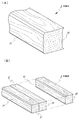
次に、本面材2の詳細について説明する。本面材2は、同一横断面形及び同一長さの複数の角柱木軸材(以下、「木軸材」と略称する。)3、3、3、・・・から構成している。
Next, the details of the facing
この木軸材3は、対向側面の一方側の全長に渡って凸条31を形成すると共に、他方側の対向面側には凹条32を形成している。凸条31は、長手側の両方の稜線部を面取り成形して全体で凸条31を成し、凹条32はこの凸条31に適合するように稜線部の両端を残して全体を削った形状にしている。
This
本面材2は、上記構成の複数の木軸材3の側面を接合させ、面状を成すように並設して構成している。この側面当接時には、側面の形成した上記凹条32と凸条31とを適合させている。そして、この並設状態の木軸材3に対し、少なくとも2本の木軸材3に跨る長さの木材用ビス5aを複数箇所へねじ込み、この木材用ビス5aと各木軸材3とを結着させて一体化している。
The
ここで、本実施例の木材用ビス5aは、そのネジ部51がその全長に渡って複数の木軸材3と深く結着している。
Here, the
この木材用ビス5aをねじ込む木軸材3の高さ位置は、その側面の高さ寸法のほぼ中央とする一方、ねじ込み方向は木軸材3の長さ方向に対して直角方向と斜め方向を組み合わせている。また、木材用ビス5aの長さは、上述のように2本の木軸材3に跨る長さの他、3本の木軸材3に跨る合計2種類の寸法を設定している。ここで、2本の木軸材3に跨る長さの木材用ビスは短めの木材用ビス5aと、3本の木軸材3に跨る長さの木材用ビスは長めの木材用ビス5bと、称して用いる。
The height position of the
本面材2における複数の木材用ビス5a、5bのねじ込み締結態様は、中央に直角方向のねじ込む方向のグループ、その両側に中央に向かう斜め方向のねじ込む方向のグループ、その外側に直角方向のねじ込む方向のグループ、となるようにしている。
A plurality of
そして、上記構成の本面材2を、木軸材3が縦方向となるように土台92に立設させた状態で柱93の間に取付けて本構造1を構築している。この軸組材9への取付けにおいては、上述のように、横側は柱93の外側から本面材2に向かって直角方向に複数の固定ビス6bをねじ込み締結し、下側は本面材2から土台92に向かって斜め方向に複数の固定ビス6aをねじ込み締結し、上側は桁94から本面材2に向かって斜め方向に複数の固定ビス6aをねじ込み締結している。
And this
また、本面材2の左右に位置する柱93については、木軸材3と当接状態を強固にすると共に隙間を生じさせないために、長さ方向に隣接する木軸材3と適合する凹条又は凸条を片側の側面にのみ形成している。
Moreover, about the
上記構成の本面材2の形成は、以下のようにして行っている。
まず、2本の木軸材3を互いの凹条32と凸条31が適合するように並設して配置する。並設後には、木軸材3を固定して凸条側の側面から下穴4を長さ方向に対して直角方向に開孔する。下穴4の開孔位置は、木軸材3の側面の高さ寸法のほぼ中央であり、長さ方向に所定間隔を確保する。また、下穴4の開孔深さに関しては、少なくとも2本の木軸材3に跨る長さとする。この場合、2本の木軸材3を貫通しても良く、又は一部の下穴4については斜め方向に開孔しても良い(図示省略)。
Formation of this
First, the two
下穴4の開孔後には、各下穴位置に下穴径よりも若干拡径した木材用ビス5aをそれぞれねじ込む。この木材用ビス5aは、そのねじ込み締結によってネジ部51が木軸材3と強固に結着する。木材用ビス5aの長さは下穴深さとほぼ同じとしている。
After opening the pilot hole 4, a
次に、一体化した2本の木軸材3、3の凸条側に新たな木軸材3を配置し、新たな木軸材3の凹条32を一体化した木軸材3の凸条31に適合させて側面どうしを当接させる。この状態で、木材用ビス5aをねじ込みした位置と異なる位置に複数の下穴4を開孔する。所定数の下穴4の開孔の終了後には、この下穴4に木材用ビス5aをねじ込んでいく。なお、一部の下穴深さについては、適宜に3本の木軸材3に跨るように設定しても良く、これにねじ込む木材用ビス5bは当然に長く設定している。
Next, a new
必要な木材用ビス5a、5bのねじ込み後は、新たな木軸材3の追加、ねじ込み後の木材用ビス5a、5bに干渉しない位置への下穴4の開孔、この下穴4に対して適宜の木材用ビス5a、5bのねじ込みを繰り返し、所定本数の木軸材3から成る本面材2の形成が完了する。
After screwing in the
上記実施例の本面材2については、木軸材3を縦方向に立設させると共に、木材用ビス5a、5bのねじ込み締結態様を変えた耐力壁7、8を構築した。そして、耐力壁7、8において「耐力壁及びその倍率性能評価試験」を行ったところ良好な結果を得ている。
With respect to the
なお、「耐力壁及びその倍率性能評価試験」の詳細については、「木造耐力壁及びその倍率の試験・評価業務方法書/http://www.jtccm.or.jp/Portals/0/resources/library/jtccm/seino/siryo/houhousho/jikugumikabe.pdf、又は木造の耐力壁及びその倍率性能試験・評価業務方法書/http://www.cbl.or.jp/standard/kseino/11/file/01.pdf」等に準拠するものであるため、本明細書での詳細な説明は省略する。 In addition, about the details of "bearing wall and its magnification performance evaluation test", examination, evaluation procedure manual / http://www.jtccm.or.jp/Portals/0/resources/ of wooden bearing wall and the magnification. library / jtccm / seino / siryo / houhousho / jikugumikabe.pdf, or wooden load-bearing wall and its magnification / performance test / evaluation procedure / http://www.cbl.or.jp/standard/kseino/11/file/ Since the document conforms to "01. pdf" etc., the detailed description in the present specification is omitted.
まず、図5に示す耐力壁7については、1辺105mm、長さ2515mmの木軸材の8本から成り、これを所定の基礎91、土台92、柱93、桁94から成る軸組材9に2種類の長さの固定ビス6a、6bで取付けている。
First, the load-bearing wall 7 shown in FIG. 5 is composed of eight wooden stems of 105 mm long and 2515 mm long, and this is a framework 9 comprising a
本面材2にねじ込む木材用ビス5a、5bの寸法としては、直径6.5mm、短めが全長200mm、長めが全長260mmとしている。ねじ込む位置としては、木軸材間の一体化用として短めの木材用ビス5aが6本、長めの木材用ビス5bが29本であり、これを木軸材3の長さ方向に対して直角及び斜め方向の組み合わせとしている。そして、この耐力壁7の壁倍率としては、3.08の結果を得た。
The dimensions of the wood screws 5a and 5b to be screwed into the
なお、軸組材9への固定については、木材用ビス5aと直径が同じであるが、これよりも全長が短めの固定ビス6aと、長めの木材用ビス5bと直径も全長も同じ長めの固定ビス6bの2種類を用いている。土台92及び桁94への固定には短めの固定ビス6aの16本をもって行い、柱93への固定には長めの固定ビス6bの16本をもって行っている。なお、長めの固定ビス6bについては、一部を斜め方向へのねじ込み締結としている。
In addition, about fixation to the shaft assembly material 9, although the diameter is the same as the
次に、図6に示す耐力壁8については、上記同様の8本の木軸材3の構成である点と、取付け対象の軸組材9を同じとしている。一方で、木軸間3の一体化用としては、全てが短めの木材用ビス5aを直角方向へねじ込み締結した合計49本で行っている。また、柱93への取付けについては、長めの固定ビス6bを直角方向へねじ込み締結した合計16本で行っている。この耐力壁8の壁倍率としては、2.18の結果を得た。
Next, about the bearing wall 8 shown in FIG. 6, the point which is the structure of the same eight
1 本構造
2 本面材
3 木軸材
31 凸条
32 凹条
4 下穴
5a 木材用ビス(短め)
5b 木材用ビス(長め)
51 ネジ部
6a 固定ビス(短め)
6b 固定ビス(長め)
7 耐力壁
8 耐力壁
9 軸組材
91 基礎
92 土台
93 柱
94 桁
Reference Signs List 1
5b wood screw (long)
51
6b Fixed screw (long)
7 load bearing wall 8 load bearing wall 9
Claims (7)
該固定一体化が、前記木軸材ごとに、前記木軸材の1本又は2本を貫通し得る長さを有する2種類の複数本の木材用ビスを、同方向側に当接した1本又は2本の木軸材に向けて、かつ適宜の間隔をもってねじ込み締結して成り、
上記各ねじ込み箇所には、当該箇所にねじ込む木材用ビス長とほぼ同じ長さでかつ小径で直線状の下穴を、予め開孔して成ることを特徴とする木軸材構成の耐力面材。 A load-bearing face material in which a plurality of three or more pieces of prismatic wood shaft members having the same cross-sectional shape are erected on a base and brought into side contact with each other to be flush and fixed.
A plurality of two or more wood screws having a length capable of penetrating one or two of the wood shaft members in the fixed and integrated manner abutted in the same direction on each of the wood shaft members 1 toward this or two trees shaft material, and made by screwing fastening with an appropriate interval,
A load-bearing face material of wooden shaft construction characterized in that a straight preliminary hole of a length and a small diameter which is approximately the same length and small diameter as a wood screw screwed into the above-mentioned screwing point is formed in each of the above screwed points. .
木軸材の長さ方向に対して直角方向、斜め方向、又はこれらの組合せであることを特徴
とする請求項1記載の木軸材構成の耐力面材。 The screwing direction of the wood screw is
2. A load-bearing face material according to claim 1, wherein the direction is perpendicular to the longitudinal direction of the wood shaft, oblique direction, or a combination thereof.
側面に形成した凹条又は凸条の適合によるものであることを特徴とする請求項1又は2
記載の木軸材構成の耐力面材。 The side contact of square timber axis material,
The method according to claim 1 or 2, characterized by the matching of the concave or convex formed on the side surface.
Load-bearing face material of the wood shaft composition described.
り付けて耐力壁面としたことを特徴とする木造軸組構法の耐力面構造。 A load-bearing surface structure of a wooden frame construction method characterized in that the load-bearing face material of the wooden shaft construction according to claim 1, 2 or 3 is attached between the frame members of the wooden frame construction method to make a load-bearing wall surface. .
耐力面材を取り付け固定する部位の軸組材の柱又は間柱と同一横断面形であることを特徴とする請求項4記載の木造軸組構法の耐力面構造。 The cross-sectional shape of the square column wood shaft material that makes up the load bearing surface material is
The load-bearing surface structure of the wooden framework method according to claim 4, which has the same cross-sectional shape as that of a column or a stud of a shaft member at a portion where the load-bearing surface member is attached and fixed.
壁面であることを特徴とする請求項4又は5記載の木造軸組構法の耐力面構造。 The part where the load bearing surface is attached is
The load-bearing surface structure of the wooden framework method according to claim 4 or 5, characterized in that it is a wall surface.
前記耐力面材を構成する角柱木軸材を、縦方向にして土台に立設させて木造軸組の柱間又は間柱間に取り付け固定したことを特徴とする木造軸組構法の耐力面構造。 In the case of constructing the bearing surface structure of claim 4 as a bearing wall,
A load-bearing surface structure of a wooden framework construction characterized in that a square column-shaped timber constituting the load-bearing surface is vertically installed on a foundation in a vertical direction and is fixed between columns or studs of a wooden framework.
Priority Applications (1)
| Application Number | Priority Date | Filing Date | Title |
|---|---|---|---|
| JP2017134420A JP6522055B2 (en) | 2017-07-10 | 2017-07-10 | Load-bearing face of timber structure and load-bearing surface of wooden frame construction method using it |
Applications Claiming Priority (1)
| Application Number | Priority Date | Filing Date | Title |
|---|---|---|---|
| JP2017134420A JP6522055B2 (en) | 2017-07-10 | 2017-07-10 | Load-bearing face of timber structure and load-bearing surface of wooden frame construction method using it |
Publications (2)
| Publication Number | Publication Date |
|---|---|
| JP2019015127A JP2019015127A (en) | 2019-01-31 |
| JP6522055B2 true JP6522055B2 (en) | 2019-05-29 |
Family
ID=65357467
Family Applications (1)
| Application Number | Title | Priority Date | Filing Date |
|---|---|---|---|
| JP2017134420A Active JP6522055B2 (en) | 2017-07-10 | 2017-07-10 | Load-bearing face of timber structure and load-bearing surface of wooden frame construction method using it |
Country Status (1)
| Country | Link |
|---|---|
| JP (1) | JP6522055B2 (en) |
Family Cites Families (4)
| Publication number | Priority date | Publication date | Assignee | Title |
|---|---|---|---|---|
| JPH076335U (en) * | 1993-06-30 | 1995-01-31 | 松代 昌久 | Unit type woodwork building materials |
| JP3896264B2 (en) * | 2001-08-29 | 2007-03-22 | 隆重 篠原 | Wood board connection panel |
| JP2003306994A (en) * | 2002-02-18 | 2003-10-31 | Daiken Kagaku:Kk | Building panel |
| JP2007046335A (en) * | 2005-08-10 | 2007-02-22 | Takahashi Shinkichi Kenchiku Kenkyusho:Kk | Framework wall structure |
-
2017
- 2017-07-10 JP JP2017134420A patent/JP6522055B2/en active Active
Also Published As
| Publication number | Publication date |
|---|---|
| JP2019015127A (en) | 2019-01-31 |
Similar Documents
| Publication | Publication Date | Title |
|---|---|---|
| JP6872280B2 (en) | Assembled limit reinforced wood steel rough surface sleeve composite node | |
| JP5953075B2 (en) | Wood | |
| JP6503318B2 (en) | Connected structure | |
| JP6682400B2 (en) | Structural structure of wooden building Joint structure of frame | |
| US11391043B2 (en) | Modular system and kit for the dry building of structures for constructions, as well as a building method thereof | |
| JP5920748B1 (en) | Wooden building structure | |
| JP2016037797A (en) | Column-beam joining structure | |
| JP4948934B2 (en) | Material fastener | |
| JP6427120B2 (en) | Bonding structure of wooden frame | |
| JP5649553B2 (en) | Connected structure | |
| JP6522055B2 (en) | Load-bearing face of timber structure and load-bearing surface of wooden frame construction method using it | |
| JP7220049B2 (en) | CLT junction structure | |
| JP2014005694A (en) | Coach screw and connector using the same | |
| WO2010098254A1 (en) | Building unit structural member and floor structure utilizing said unit structural member | |
| JP3209111U (en) | Vertical frame material and steel house | |
| JP2016070022A (en) | Connecting structure | |
| JP7062463B2 (en) | Connection structure | |
| JP6667273B2 (en) | Mounting structure of tension rod | |
| JP5415464B2 (en) | Connected structure | |
| JP6163508B2 (en) | Log house | |
| JP2016020076A (en) | Prestress introduced accumulation plate | |
| JP6808196B2 (en) | Connected structure | |
| JP5933806B2 (en) | Joint structure of column and horizontal member in wooden frame | |
| JP2014214497A (en) | Wooden beam joint structure and wooden beam joint method | |
| JP3895696B2 (en) | Building connection panels and building structures |
Legal Events
| Date | Code | Title | Description |
|---|---|---|---|
| A02 | Decision of refusal |
Free format text: JAPANESE INTERMEDIATE CODE: A02 Effective date: 20180117 |
|
| A521 | Request for written amendment filed |
Free format text: JAPANESE INTERMEDIATE CODE: A523 Effective date: 20190212 |
|
| A521 | Request for written amendment filed |
Free format text: JAPANESE INTERMEDIATE CODE: A523 Effective date: 20190315 |
|
| A61 | First payment of annual fees (during grant procedure) |
Free format text: JAPANESE INTERMEDIATE CODE: A61 Effective date: 20190423 |
|
| R150 | Certificate of patent or registration of utility model |
Ref document number: 6522055 Country of ref document: JP Free format text: JAPANESE INTERMEDIATE CODE: R150 |
|
| R250 | Receipt of annual fees |
Free format text: JAPANESE INTERMEDIATE CODE: R250 |