[1.パチンコ機の全体構造]
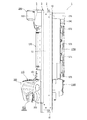
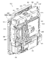
以下、図面を参照して本発明の好適な実施形態について、図面を参照して説明する。まず、図1乃至図7を参照して実施形態に係るパチンコ機の全体について説明する。図1は実施形態に係るパチンコ機の外枠に対して本体枠を開放し、本体枠に対して扉枠を開放した状態を示す斜視図であり、図2はパチンコ機の正面図であり、図3はパチンコ機の側面図であり、図4はパチンコ機の平面図であり、図5はパチンコ機の背面図であり、図6はパチンコ機を構成する外枠、本体枠、遊技盤、扉枠の後方から見た分解斜視図であり、図7はパチンコ機を構成する外枠、本体枠、遊技盤、扉枠の前方から見た分解斜視図である。
[1. Overall structure of pachinko machine]
Hereinafter, preferred embodiments of the present invention will be described with reference to the drawings. First, the entire pachinko machine according to the embodiment will be described with reference to FIGS. 1 to 7. FIG. 1 is a perspective view showing a state in which a main frame is opened to an outer frame of a pachinko machine according to the embodiment and a door frame is opened to the main frame, and FIG. 2 is a front view of the pachinko machine 3 is a side view of the pachinko machine, FIG. 4 is a plan view of the pachinko machine, FIG. 5 is a rear view of the pachinko machine, and FIG. 6 is an outer frame constituting the pachinko machine, a main frame, a game board, FIG. 7 is an exploded perspective view seen from the rear of the door frame, and FIG. 7 is an exploded perspective view seen from the front of the outer frame, the main body frame, the game board, and the door frame constituting the pachinko machine.
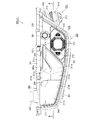
図1乃至図7において、本実施形態に係るパチンコ機1は、遊技ホールの島(図示しない)に設置される外枠2と、外枠2に開閉自在に軸支され且つ遊技盤4を装着し得る本体枠3と、本体枠3に開閉自在に軸支され且つ遊技盤4に形成されて球が打ち込まれる遊技領域605を遊技者が視認し得る遊技窓101とその遊技窓101の下方に配置され且つ遊技の結果によって払出される球を貯留する貯留皿としての皿ユニット300とを備えた扉枠5と、を備えて構成されている。
In FIG. 1 to FIG. 7, the pachinko machine 1 according to the present embodiment has an outer frame 2 installed on an island (not shown) of the game hall and an open / close pivotal support on the outer frame 2 and mounting the game board 4 The game window 101 in which the player can visually recognize the main body frame 3 which can be made, and the game area 605 which is pivotally supported by the main body frame 3 so as to be openable and closable and is formed on the game board 4 and into which a ball is struck And a door frame 5 provided with a tray unit 300 as a storage tray which is disposed and stores balls to be paid out as a result of the game.
外枠2には、その下方前方に装飾カバー板15を補強するカバー補強金具14が固着されている。また、本体枠3には、上記したように遊技盤4が着脱自在に装着し得る他に、その裏面下部に打球発射装置650と、遊技盤4を除く扉枠5や本体枠3に設けられる電気的部品を制御するための各種の制御基板や電源基板1136等が一纏めに設けられている基板ユニット1100が取付けられ、本体枠3の後面開口580(図6を参照)を覆うカバー体1250が着脱自在に設けられている。更に、扉枠5には、上記した皿ユニット300の他に、遊技窓101を閉塞するようにガラスユニット450と、ハンドル装置400とが設けられている。そして、本実施形態の特徴は、扉枠5に設けられる皿ユニット300が1つであり、しかも、従来は本体枠3に設けられていたハンドル装置400が扉枠5に設けられ、また、扉枠5と本体枠3とが正面から見て略同じ方形の大きさであるため、正面から本体枠3が視認できなくした点である。以下、パチンコ機1を構成する部材について詳細に説明する。
A cover reinforcing bracket 14 for reinforcing the decorative cover plate 15 is fixed to the lower front of the outer frame 2. In addition to the game board 4 being detachably attachable to the main body frame 3 as described above, it is provided on the bottom of the back surface with a ball striking device 650 and the door frame 5 excluding the game board 4 and the main body frame 3 A substrate unit 1100 is attached to which various control substrates for controlling electrical parts, a power supply substrate 1136 and the like are provided together, and a cover 1250 covering a rear opening 580 (see FIG. 6) of the main body frame 3 is provided. It is provided detachably. Furthermore, in addition to the plate unit 300 described above, the door frame 5 is provided with a glass unit 450 and a handle device 400 so as to close the game window 101. And, the feature of this embodiment is that there is one plate unit 300 provided in the door frame 5, and furthermore, the handle device 400 conventionally provided in the main body frame 3 is provided in the door frame 5, and the door Since the frame 5 and the body frame 3 have substantially the same rectangular size when viewed from the front, the body frame 3 can not be viewed from the front. Hereinafter, members constituting the pachinko machine 1 will be described in detail.
[1−1.外枠]
外枠2について、主として図8乃至図12を参照して説明する。図8は、外枠2の正面斜視図であり、図9は、同外枠2の正面から見た分解斜視図であり、図10は、同外枠2の正面図であり、図11は、同外枠2の背面図であり、図12は、図10のB−B断面図(A)と図12(A)のC−C断面図(B)、D−D断面図(C)、E−E断面図(D)である。また、図13は本体枠の上軸支金具と外枠の上支持金具との脱着構造を説明するための斜視図であり、図14は外枠の上支持金具の裏面に設けられるロック部材の取付状態を示す分解斜視図(A)と下方から見た斜視図(B)である。更に、図15は軸支ピンとロック部材との関係を説明するための上支持金具部分の裏面図であり、図16はロック部材の作用を説明するための上支持金具部分の裏面図である。
[1-1. Outer frame]
The outer frame 2 will be described mainly with reference to FIGS. 8 to 12. 8 is a front perspective view of the outer frame 2, FIG. 9 is an exploded perspective view seen from the front of the outer frame 2, FIG. 10 is a front view of the outer frame 2, and FIG. 12 is a cross-sectional view taken along the line B-B in FIG. 10 (A), a cross-sectional view taken along the line C-C in FIG. 12 (A) (B), a cross-sectional view taken along the line D-D (C) , E-E cross-sectional view (D). FIG. 13 is a perspective view for explaining the attachment / detachment structure of the upper shaft support bracket of the main body frame and the upper support bracket of the outer frame, and FIG. 14 is a lock member provided on the back surface of the upper support bracket of the outer frame. They are the disassembled perspective view (A) which shows an attachment state, and the perspective view (B) seen from the downward direction. Further, FIG. 15 is a back view of the upper support fitting portion for explaining the relationship between the pivot pin and the lock member, and FIG. 16 is a back view of the upper support fitting portion for explaining the operation of the lock member.
図8及び図9において、本実施形態に係る外枠2は、横方向へ延びる上下の上枠板10及び下枠板11と、縦(上下)方向へ延びる左右の側枠板12,13とを、夫々の端部を連結するための連結部材19で連結することによって方形状に組み付けられるものである。具体的には、連結部材19は、中央と左右とに段差のある表彰台状に形成され、突出した中央の部分が上枠板10及び下枠板11の両端部中央に形成された係合切欠部20に嵌合され、一段下がった左右の部分の平面に上枠板10の裏面と下枠板11の上面とが当接し且つ一段下がった左右の部分の一側面に側枠板12,13の内側面が当接するようになっている。
In FIGS. 8 and 9, the outer frame 2 according to the present embodiment includes upper and lower upper and lower frame plates 10 and 11 extending in the horizontal direction, and left and right side frame plates 12 and 13 extending in the vertical (vertical) direction. Are assembled in a square shape by connecting them with connecting members 19 for connecting the respective end portions. Specifically, the connecting member 19 is formed in a podium shape having a level difference between the center and the left and right, and an engagement notch in which a protruding center portion is formed at the center of both ends of the upper frame plate 10 and the lower frame plate 11 The side frame plates 12 and 13 are fitted on the side surface of the left and right portions of which the back surface of the upper frame plate 10 and the upper surface of the lower frame plate 11 are in contact with the flat surface of the left and right portions. The inner surface of the is in contact.
そして、その状態で、上枠板10の係合切欠部20の両側方及び下枠板11の係合切欠部20の両側方に夫々形成される挿通穴21と連結部材19の一段下がった左右の部分の平面に形成される複数(図示の場合2個)の連結穴22(図9の上枠板10と側枠板12とを連結する連結部材19に表示するが、他の連結部材19にも存在する)とを一致させて上方又は下方から複数(図示の場合2本)の連結ビス23で止着し、更に、側枠板12,13の上下端部分に穿設される複数(図示の場合2個)の取付穴24と連結部材19の一段下がった左右の部分の側面に形成される複数(図示の場合3個)の連結穴25とを一致させて側方外側から複数(図示の場合3本)の連結ビス26,27で止着することにより、上下の上枠板10及び下枠板11と左右の側枠板12,13とが強固に連結固定される。ただし、3本の連結ビス26,27のうち、1本の連結ビス27は、側枠板12,13と連結部材19とを連結するものではなく、上枠板10及び下枠板11と連結部材19とを側方から直接連結するものである。
Then, in this state, the insertion hole 21 and the connecting member 19 which are formed in the both sides of the engagement notch 20 of the upper frame plate 10 and the both sides of the engagement notch 20 of the lower frame 11 respectively are one step lower (Two in the case of illustration) connection holes 22 (the upper frame plate 10 and the side frame plate 12 of FIG. (In the illustrated case) and is fastened with a plurality of (two in the illustrated case) connection screws 23 from the upper or lower side, and further, a plurality (two or more) In the illustrated case, two (two in the figure) mounting holes 24 and a plurality (three in the case of the figure) of connecting holes 25 formed on the side surfaces of the left and right portions of the connecting member 19 are made coincident with each other. In the illustrated case, the upper and lower upper frame plates 10 and the lower frame are fixed by fastening them with the three connection screws 26 and 27). 11 and the left and right side frame plates 12 and 13 is firmly coupled and fixed. However, among the three connection screws 26 and 27, one connection screw 27 does not connect the side frame plates 12 and 13 to the connection member 19, but connects the upper frame plate 10 and the lower frame plate 11. It directly connects with the member 19 from the side.
外枠2を構成する上枠板10と下枠板11、及び側枠板12,13のうち、上枠板10と下枠板11とは従来と同じ木製であり、側枠板12,13は、軽量金属、例えば、アルミニュウム合金の押出し成型板により構成されている。上枠板10及び下枠板11を従来と同じ木製で構成した理由は、パチンコ機1を遊技場に列設される島に設置する場合に、島の垂直面に対し所定の角度をつけて固定する作業を行う必要があるが、そのような作業は上枠板10及び下枠板11と島とに釘を打ち付けて行われるため、釘を打ち易くするためである。一方、側枠板12,13をアルミニュウム合金の押出し成型板により構成した理由は、従来の木製に比べ強度を維持しつつ肉厚を薄く形成することができるため、側枠板12,13の内側に隣接する本体枠3の側面壁540〜543(図69を参照)の正面から見たときの左右幅を広くすることができる。このため左右方向の寸法の大きな遊技盤4を本体枠3に装着することができることになり、結果的に遊技盤4の遊技領域605を大きく形成することができるからである。
Of the upper frame plate 10 and the lower frame plate 11 and the side frame plates 12 and 13 constituting the outer frame 2, the upper frame plate 10 and the lower frame plate 11 are made of the same wooden as in the prior art, and the side frame plates 12 and 13 Is made of an extruded sheet of lightweight metal such as aluminum alloy. The reason why upper frame plate 10 and lower frame plate 11 are made of the same wooden as in the prior art is that when pachinko machine 1 is installed on an island in a row in a game arcade, a predetermined angle is given to the vertical surface of the island. Although it is necessary to carry out a fixing operation, such an operation is performed by striking a nail on the upper frame plate 10 and the lower frame plate 11 and the island, so that the nail is easy to strike. On the other hand, the reason why the side frame plates 12 and 13 are formed of an aluminum alloy extruded plate is that the thickness can be formed thinner while maintaining the strength compared to the conventional wood, so the inner side of the side frame plates 12 and 13 When viewed from the front of the side walls 540 to 543 (see FIG. 69) of the main body frame 3 adjacent to each other, the lateral width can be widened. Therefore, the game board 4 having a large dimension in the left-right direction can be attached to the main frame 3, and as a result, the game area 605 of the game board 4 can be formed large.
なお、側枠板12,13をアルミニュウム合金の平板で構成すると、充分な剛性が確保できないため、図12(C)に示すように、側枠板12(側枠板13も全く同じ構造である。)の後方部分内側にリブによって後方が開放した空間部28(側枠板13の空間部28は図11に表示)を形成して後方部分の肉厚h1が厚くなるように引き抜き成型されている。もちろん、この肉厚h1は、従来の木製の肉厚と同等若しくは若干薄い寸法となっている。
If the side frame plates 12 and 13 are formed of aluminum alloy flat plates, sufficient rigidity can not be secured. Therefore, as shown in FIG. 12C, the side frame plates 12 (the side frame plates 13 have the same structure as well. A space 28 (the space 28 of the side frame plate 13 is shown in FIG. 11) opened rearward by a rib on the inner side of the rear part of T.) is drawn out and formed to increase the thickness h1 of the rear part There is. Of course, this thickness h1 has a size equal to or slightly smaller than that of the conventional wood.
また、図12(B),(D)に示すように、側枠板12の空間部28の前方には、連結部材19の一段下がった左右の部分の一方の部分が嵌め込まれる溝部29(側枠板13の溝部29は図8に表示)が形成されている。側枠板12の溝部29から前端部までは、図12(B)〜(D)に示すように、その内側面が連結部材19の一段下がった左右の部分の他方の部分が当接する平板状をなすものであるが、その平板部に材料軽減のための浅い凹部が形成されている。更に、溝部29が形成される反対側の面(外側面)には、図8及び図12(B)に示すように、上支持金具45の垂下片部53が挿入される凹部30(側枠板13の凹部30は図9に表示)が形成されている。
Further, as shown in FIGS. 12B and 12D, in the front of the space portion 28 of the side frame plate 12, one of the left and right portions of the connecting member 19 which is one step lower than the groove portion 29 (the side The groove 29 of the frame plate 13 is formed as shown in FIG. From the groove portion 29 to the front end portion of the side frame plate 12, as shown in FIGS. 12B to 12D, the inner side surface thereof is a flat plate in which the other portion of the left and right portions one step lower However, the flat portion has a shallow recess for material reduction. Furthermore, as shown in FIGS. 8 and 12B, a recess 30 (a side frame in which the hanging piece 53 of the upper support fitting 45 is inserted into the opposite surface (outside surface) where the groove 29 is formed. The recess 30 of the plate 13 is formed as shown in FIG.
そして、上記のように形成される軸支側の側枠板12には、連結部材19を取付けるための構成以外に、その上部に上支持金具45の垂下片部53を側枠板12の外側に止着ビス32で止着するための取付穴31が穿設されると共に、その下部に下支持金具66の垂直当接片72に形成される取付穴69と一致させて止着ビス34で止着するための取付穴33が穿設されている。また、取付穴33の下部であって側枠板12の前方部分に側枠板12とカバー補強金具14とを止着ビス36で止着するための取付穴35が形成されている。
Further, in the side frame plate 12 on the pivotal support side formed as described above, the drooping piece portion 53 of the upper support fitting 45 is provided on the upper side of the side frame plate 12 in addition to the configuration for attaching the connecting member 19. The mounting holes 31 for fixing with the fixing screws 32 are formed at the same time and are made to coincide with the mounting holes 69 formed in the vertical contact pieces 72 of the lower support fitting 66 at the lower part thereof. An attachment hole 33 for fastening is formed. A mounting hole 35 for fixing the side frame plate 12 and the cover reinforcing fitting 14 with a fixing screw 36 is formed in the front portion of the side frame plate 12 below the mounting hole 33.
一方、開放側の側枠部13には、連結部材19を取付けるための構成以外に、その上部に閉鎖用突起38を取付ネジ39で取付けるための取付穴37が穿設され、その下部に閉鎖用突起41を取付ネジ42で取付けるための取付穴40が穿設されると共に、さらに最下方に側枠板13とカバー補強金具14とを止着ビス44で止着するための取付穴43が形成されている。
On the other hand, in the side frame portion 13 on the open side, in addition to the configuration for attaching the connection member 19, an attachment hole 37 for attaching the closing projection 38 with the attachment screw 39 is drilled in the upper portion. The mounting hole 40 for mounting the projection 41 with the mounting screw 42 is drilled, and the mounting hole 43 for fixing the side frame plate 13 and the cover reinforcing bracket 14 at the lowermost position with the fixing screw 44 is further provided. It is formed.
なお、この閉鎖用突起38,41は、外枠2に対して本体枠3を閉じる際に、本体枠3の開放側辺に沿って取付けられる錠装置1000のフック部1054,1065(図121を参照)と係合するものであり、後に詳述するように錠装置1000のシリンダ錠1010に鍵を差し込んで一方に回動することにより、フック部1054,1065と閉鎖用突起38,41との係合が外れて本体枠3を外枠2に対して開放することができるものである。
Note that when the main body frame 3 is closed with respect to the outer frame 2, the closing projections 38 and 41 are hook portions 1054 and 1065 (see FIG. 121) of the lock device 1000 attached along the open side of the main body frame 3. And lock the cylinder lock 1010 of the lock device 1000 and pivot it to one side, as will be described in detail later. The engagement can be released to open the main body frame 3 to the outer frame 2.
また、下枠板11と左右の側枠板12,13の下部前面に固定されるカバー補強金具14は、閉止時においてその上面に本体枠3が載置されるものであり、カバー補強金具14の表面及び側面は、装飾カバー板15によって被覆されている。なお、外枠2の装飾カバー板15の開放側の上面には、本体枠3の閉止時に本体枠3をスムーズに案内するための案内板18が交換可能に装着されている。
In addition, the cover reinforcement fitting 14 fixed to the lower front surface of the lower frame plate 11 and the lower side frame plates 12 and 13 is such that the main body frame 3 is placed on the upper surface at the time of closing. The surface and sides of the cover are covered with a decorative cover plate 15. A guide plate 18 for smoothly guiding the main body frame 3 when the main body frame 3 is closed is replaceably mounted on the open upper surface of the decorative cover plate 15 of the outer frame 2.
ところで、本体枠3を開閉自在に軸支する構造として、上枠板10と側枠板12とを連結する機能も兼用する上支持金具45とカバー補強金具14の一側上面に沿って取付けられる下支持金具66とが設けられている。上支持金具45には、前方に突出している支持突出片46に支持突出片46の側方から先端中央部に向かって屈曲して形成された支持鉤穴47が形成されており、この支持鉤穴47に本体枠3の後述する上軸支金具503の軸支ピン504(図71を参照)が着脱自在に係合されるようになっている。
By the way, it is attached along one side upper surface of upper support fitting 45 and cover reinforcement fitting 14 which also has a function of connecting upper frame plate 10 and side frame plate 12 as a structure for pivotally supporting body frame 3 so as to open and close freely. A lower support fitting 66 is provided. The upper support fitting 45 is formed with a support hook 47 which is formed by being bent toward the center of the tip from the side of the support projection 46 in the support projection 46 projecting forward. An axial support pin 504 (see FIG. 71) of an upper axial support bracket 503 of the main body frame 3 described later is detachably engaged with the hole 47.
また、下支持金具66も前方に突出した形状に形成されているが、この突出した部分に上向きに支持突起68が突設され、この支持突起68に本体枠3の後述する枠支持板506(図72を参照)に形成される支持穴が挿入される。したがって、外枠2に本体枠3を支持するためには、下支持金具66の支持突起68に本体枠3の枠支持板506に形成される支持穴を係合させた後、本体枠3の上軸支金具503の軸支ピン504を支持鉤穴47に掛け止めることにより簡単に開閉自在に軸支することができる。
Further, the lower support fitting 66 is also formed in a shape projecting forward, but a support projection 68 is projected upward from this projecting portion, and a frame support plate 506 (described later) of the main body frame 3 The support hole formed in FIG. 72) is inserted. Therefore, in order to support the main frame 3 on the outer frame 2, after engaging the support holes formed in the frame support plate 506 of the main frame 3 with the support protrusions 68 of the lower support bracket 66, By pivotally supporting the support pin 504 of the upper shaft support 503 in the support hole 47, the shaft can be supported in a freely open / close manner.
また、上支持金具45は、上枠板10の軸支側の上面及び前面に凹状に形成される取付段部49に装着されるものであるが、その装着に際し、上支持金具45に形成される複数(図示の場合2個)の取付穴48と取付段部49に穿設される複数(図示の場合2個)の取付穴50とを一致させて取付ビス51を上方から差し込み、上枠板10の裏面から押し当てられる挟持板52に止着することにより上支持金具45が上枠板10に堅固に固定される。
The upper support fitting 45 is mounted on the mounting step 49 formed concavely on the upper surface and the front surface of the upper frame plate 10 on the support side. The mounting screw 51 is inserted from the top by aligning the mounting holes 48 (two in the case of illustration) and the mounting holes 50 (two in the case of illustration) formed in the mounting step 49 with one another. The upper support fitting 45 is firmly fixed to the upper frame plate 10 by fixing to the holding plate 52 pressed from the back surface of the plate 10.
また、上支持金具45の外側側方には、側枠板12の外側に当接する垂下片部53があり、その垂下片部53にも取付穴が穿設され、この取付穴と取付穴31とを止着ビス32で止着することにより、上支持金具45と側枠板12とを固定すると共に、上枠板10と側枠板12とを上支持金具45を介して連結している。
Further, on the outer side of the upper support fitting 45, there is a hanging piece portion 53 that abuts the outside of the side frame plate 12, and in the hanging piece portion 53, a mounting hole is bored. The upper support fitting 45 and the side frame plate 12 are fixed and the upper frame plate 10 and the side frame plate 12 are connected via the upper support fitting 45 by fixing them with the fixing screw 32. .
一方、下支持金具66は、前述したように側枠板12の取付穴33と垂直当接片72の取付穴69とを一致させた状態で止着ビス34で止着し、さらに、下支持金具66の水平面の中程に穿設される取付穴70に取付ネジ71を差し込むことにより、装飾カバー板15を介してカバー補強金具14の上面に止着されるものである。
On the other hand, the lower support fitting 66 is fixed by the fixing screw 34 in a state in which the mounting hole 33 of the side frame plate 12 and the mounting hole 69 of the vertical contact piece 72 are aligned as described above. The mounting screw 71 is inserted into the mounting hole 70 drilled in the middle of the horizontal surface of the metal fitting 66 so that it is fixed to the upper surface of the cover reinforcing metal fitting 14 via the decorative cover plate 15.
上記のように構成される外枠2において、その構成部材である上枠板10と下枠板11と側枠板12,13とを連結部材19で連結することにより、連結部材19が側枠板12,13の内面に密着して止着されると共に連結部材19と上枠板10及び下枠板11が係合した状態で止着されるので、その組み付け強度が高く頑丈な方形状の枠組みとすることができる。上記した連結部材19と上枠板10及び下枠板11との係合状態に加え、連結部材19の側枠板12,13への取付けに際し、溝部29に連結部材19の一段下がった左右の部分の一方の部分が嵌め込まれる構造であるため、連結部材19の側枠板12,13への取付けが強固となり、これによっても方形状の枠組みの強度を向上することができると共にその位置決めを正確に行うことができる。
In the outer frame 2 configured as described above, the connecting member 19 is a side frame by connecting the upper frame plate 10, the lower frame plate 11, and the side frame plates 12 and 13 which are the constituent members with the connecting member 19. Since it is fixed in close contact with the inner surfaces of the plates 12 and 13 and fixed in a state in which the connecting member 19 and the upper frame plate 10 and the lower frame plate 11 are engaged, the assembly strength is high and the square shape is robust It can be a framework. In addition to the engagement between the connecting member 19 and the upper frame plate 10 and the lower frame plate 11 described above, the left and right of the connecting member 19 are lowered in the groove 29 when the connecting member 19 is attached to the side frame plates 12 and 13. Because one part of the part is fitted in, the attachment of the connecting member 19 to the side frame plates 12 and 13 becomes strong, which can also improve the strength of the rectangular frame and accurately position it. Can be done.
また、連結部材19によって上枠板10、下枠板11、側枠板12,13を連結した後、上支持金具45を所定の位置に取付けたときに、図10及び図11に示すように、各枠板10,11,12,13の外側面(外周面)から外側に突出する部材は存在しないので、パチンコ機1を図示しないパチンコ島台に設置する際に、隣接する装置(例えば、隣接する玉貸器)と密着して取付けることができる。また、下支持金具66を取付けたときにも、カバー補強金具14の上面と下支持金具66の上面とが略同一平面となるようになっている。
Also, after the upper frame plate 10, the lower frame plate 11, and the side frame plates 12 and 13 are connected by the connecting member 19, the upper support fitting 45 is mounted at a predetermined position as shown in FIGS. Since there is no member projecting outward from the outer surface (peripheral surface) of each frame plate 10, 11, 12, 13, when installing the pachinko machine 1 on a pachinko island stand (not shown), adjacent devices (for example, It can be attached in close contact with the adjacent ball lender. Also, when the lower support fitting 66 is attached, the upper surface of the cover reinforcing fitting 14 and the upper surface of the lower support fitting 66 are substantially flush with each other.
ところで、本体枠3を開閉自在に軸支するための上支持金具45の裏面には、図14に示すようにロック部材80が回動自在に軸支されている。より詳細に説明すると、図14(A)に示すように、上支持金具45の支持突出片46は、先端部が円弧状の平板として形成されると共に支持突出片46の外側縁に沿って直角に折り曲げられた垂下壁46aが形成される。この垂下壁46aにより、上支持金具45の支持突出片46の強度を向上させることができると共に、正面から見たときに次に説明するロック部材80が視認できないようにして外観を良くし、更に、次に説明するロック部材80の弾性片80cの先端当接部が当接する部位として利用したりロック部材80が支持突出片46から外側に飛び出さないように停止部として利用したりしている。また、支持突出片46に形成される支持鉤穴47は、垂下壁46aが形成されない反対側の側方から内側にやや向ってさらに先端中央部に向かって傾斜状となるように屈曲して形成されている。そして、支持鉤穴47の傾斜状穴部の溝寸法は、軸支ピン504の直径よりもやや大きな寸法に形成されている。
By the way, as shown in FIG. 14, a lock member 80 is rotatably pivotally supported on the back surface of the upper support fitting 45 for pivotally supporting the main body frame 3 in an openable / closable manner. More specifically, as shown in FIG. 14A, the support projection 46 of the upper support fitting 45 is formed as an arc-shaped flat plate at its tip and is perpendicular to the outer edge of the support projection 46. The hanging wall 46a is formed to be bent into two. The hanging wall 46a can improve the strength of the support protruding piece 46 of the upper support fitting 45, and can improve the appearance by making the lock member 80 described below invisible when viewed from the front, and further improving the appearance. Then, it is used as a portion to which the tip contact portion of the elastic piece 80c of the lock member 80 described below abuts, or as a stop portion so that the lock member 80 does not protrude outward from the support projection piece 46. . Further, the support wedging hole 47 formed in the support projecting piece 46 is formed by being bent so as to be further inclined toward the center of the tip slightly from the opposite side where the hanging wall 46a is not formed toward the inner side It is done. The groove size of the inclined hole portion of the support wedge hole 47 is formed to be slightly larger than the diameter of the pivot pin 504.
また、上記した垂下壁46aは、支持鉤穴47の前方の入口端部から支持突出片46及び上支持金具45の外側縁に沿って直角に折り曲げられて形成されていると共に、支持鉤穴47の前方の入口端部の部分で内側に向って折り曲げられて停止垂下部47aとなっている。また、支持突出片46の略中央に取付穴46bが穿設され、取付穴46bにロック部材80がリベット81によって回転自在に軸支されている。ロック部材80は、合成樹脂によって成型されるものであり、ストッパー部80aと操作部80bとがL字状に形成され、また操作部80bと反対側に円弧状の弾性片80cが一体的に延設されている。そして、ストッパー部80aと操作部80bとがなすL字状の基部にリベット81が挿通される取付穴80dが形成されている。しかして、ロック部材80がリベット81によって取付穴46bに取付けられて支持突出片46の裏面に回転自在に固定した状態においては、図14(B)に示すように、弾性片80cの先端当接部が垂下壁46aの内側面と当接しており、ストッパー部80aが支持鉤穴47の傾斜状穴部を閉塞するようになっている。また、このときストッパー部80aの先端部分は、支持鉤穴47の傾斜状穴部の先頭空間部分を閉塞した状態となっていない。即ち、通常の状態で支持鉤穴47の先頭空間部分には、本体枠3の上軸支金具503の軸支ピン504が挿入される空間が形成されている。
Further, the hanging wall 46a described above is formed by being bent at a right angle along the outer edges of the support protruding piece 46 and the upper support fitting 45 from the front inlet end of the support hole 47 and the support hole 47. Is bent inward at the front end of the inlet end portion to form a stop drooping portion 47a. Further, a mounting hole 46b is formed substantially at the center of the support protruding piece 46, and the lock member 80 is rotatably supported by the rivet 81 in the mounting hole 46b. The lock member 80 is molded of synthetic resin, the stopper portion 80a and the operation portion 80b are formed in an L shape, and the arc-shaped elastic piece 80c is integrally extended on the opposite side of the operation portion 80b. It is set up. Further, an attachment hole 80d through which the rivet 81 is inserted is formed in an L-shaped base formed by the stopper portion 80a and the operation portion 80b. Thus, in the state where the lock member 80 is attached to the attachment hole 46b by the rivet 81 and rotatably fixed to the back surface of the support projection 46, as shown in FIG. 14B, the tip contact of the elastic piece 80c The part is in contact with the inner side surface of the hanging wall 46a, and the stopper part 80a closes the inclined hole part of the support hole 47. Further, at this time, the tip end portion of the stopper portion 80 a does not close the head space portion of the inclined hole portion of the support wedge hole 47. That is, in the normal state, a space into which the pivot support pin 504 of the upper pivot support bracket 503 of the main body frame 3 is inserted is formed in the head space portion of the support hook hole 47.
ところで、軸支ピン504が支持鉤穴47の傾斜状穴部の先端空間部分に挿入されてストッパー部80aの先端側方が入口端部の停止垂下部47aに対向している状態(この状態ではストッパー部80aの先端側方と停止垂下部47aとの間に僅かな隙間があり当接した状態となっていない)である通常の軸支状態においては、屈曲して形成される支持鉤穴47の傾斜状穴部の先端空間部分に位置する軸支ピン504とストッパー部80aの先端面80eとの夫々の中心が斜め方向にずれて対向した状態となっている。そして、この通常の軸支状態においては、重量のある本体枠3を軸支している軸支ピン504が支持鉤穴47の先端部分に当接した状態となっているので、軸支ピン504からストッパー部80aの先端面80eへの負荷がほとんどかかっていないため、ロック部材80の弾性片80cに対し負荷がかかっていない状態となっている。また、図15(A)に示すように、ストッパー部80aの先端面80eが操作部80bを操作して回動したときにロック部材80がスムーズに回動するように円弧状に形成されている。図示の場合、この円弧状先端面80eの円弧中心は、リベット81の中心(ロック部材80の回転中心)である。
By the way, the state in which the support pin 504 is inserted into the end space portion of the inclined hole portion of the support hole 47 and the end side of the stopper portion 80a faces the stop drooping portion 47a of the inlet end (in this state In the usual axially supported state where there is a slight gap between the front end side of the stopper portion 80a and the stop drooping portion 47a), the support weir 47 formed by bending The respective centers of the pivotal support pin 504 located in the end space portion of the inclined hole portion and the end surface 80e of the stopper portion 80a are in a state of being shifted in the diagonal direction and facing each other. And, in this normal support state, the support pin 504 supporting the heavy main body frame 3 is in a state of being in contact with the front end portion of the support hook hole 47. Since the load on the tip end surface 80e of the stopper portion 80a is hardly applied, the load is not applied to the elastic piece 80c of the lock member 80. Further, as shown in FIG. 15A, the distal end surface 80e of the stopper portion 80a is formed in an arc shape so that the lock member 80 is smoothly rotated when the operation portion 80b is operated and rotated. . In the illustrated case, the arc center of the arc tip surface 80e is the center of the rivet 81 (the rotation center of the lock member 80).
このため、軸支ピン504が支持鉤穴47の傾斜状穴部の傾斜に沿って抜ける方向に作用力Fがかかって円弧状の先端面80eに当接したとき、その作用力Fを、軸支ピン504と円弧状の先端面80eとの当接部分に作用する分力F1(円弧状先端面80eの円弧の法線方向)と、軸支ピン504と支持鉤穴47の傾斜状穴部の一側内面との当接部分に作用する分力F2と、に分けたときに、分力F1の方向がリベット81の中心(ロック部材80の回転中心)を向くため、ロック部材80のストッパー部80aの先端部が支持突出片46から外れる方向(図示の時計方向)に回転させるモーメントが働かず、軸支ピン504がロック部材80のストッパー部80aの先端部と支持鉤穴47の傾斜状穴部の一側内面との間に挟持された状態を保持する。このため、通常の軸支状態でもあるいは軸支ピン504の作用力がロック部材80にかかった状態でも、ロック部材80の弾性片80cに常時負荷がかからず、合成樹脂で一体形成される弾性片80cのクリープによる塑性変形を防止し、長期間に亘って軸支ピン504の支持鉤穴47からの脱落を防止することができる。なお、仮に無理な力がかかってロック部材80のストッパー部80aの先端部が支持突出片46から外れる方向(図示の時計方向)に回転させられても、ストッパー部80aの先端部の一側方が停止垂下部47aに当接してそれ以上外れる方向に回転しないので、ロック部材80が支持突出片46の外側にはみ出ることはない。
For this reason, when the acting force F is applied in the direction in which the pivotal support pin 504 comes out along the inclination of the inclined hole of the support eyelet 47 and abuts on the arc-shaped tip surface 80e, the acting force F is A component force F1 (a normal direction of the arc of the arc-shaped end surface 80e) acting on the contact portion between the support pin 504 and the arc-shaped end surface 80e, and an inclined hole portion of the shaft support pin 504 and the support hook 47 Since the direction of the component force F1 faces the center of the rivet 81 (the center of rotation of the lock member 80) when divided into the component force F2 acting on the contact portion with the one side inner surface, the stopper of the lock member 80 Since the moment for rotating the tip of the portion 80a in the direction (clockwise direction in the drawing) freed from the support protrusion 46 does not work, the pivot pin 504 has an inclined shape of the tip of the stopper 80a of the lock member 80 and the support hook 47 State of being held between one side inner surface of the hole To hold. Therefore, even in the normal shaft support state or in the state where the acting force of the shaft support pin 504 is applied to the lock member 80, no load is always applied to the elastic piece 80c of the lock member 80, and the elastic integrally formed of synthetic resin It is possible to prevent plastic deformation due to creep of the piece 80c, and to prevent the support pin 504 from coming off from the support hole 47 for a long period of time. Even if the distal end of the stopper 80a of the lock member 80 is rotated in a direction (clockwise direction in the figure) that is released from the support projecting piece 46 by applying an excessive force, one side of the distal end of the stopper 80a Does not rotate in the direction in which it abuts on the stop hanging portion 47 a and thus does not rotate further, the locking member 80 does not protrude outside the support protrusion 46.
また、図15(A)に示す実施形態においては、ストッパー部80aの円弧状先端面80eの円弧中心がリベット81の中心(ロック部材80の回転中心)であることにより、軸支ピン504に対し支持鉤穴47の傾斜状穴部の傾斜に沿って抜ける方向の作用力Fがかかってもロック部材80に回転モーメントが生じないものについて説明したが、図15(B)に示すように、ストッパー部80aの円弧状先端面80fの曲率半径をさらに小さくし、且つロック部材80のリベット81による軸支位置を支持突出片46の内側にした場合に、軸支ピン504が支持鉤穴47の傾斜状穴部の傾斜に沿って抜ける方向に作用力Fがかかって円弧状の先端面80fに当接したとき、その作用力Fを、軸支ピン504と円弧状の先端面80fとの当接部分に作用する分力F1(円弧状先端面80fの円弧の法線方向)と、軸支ピン504と支持鉤穴47の傾斜状穴部の一側内面との当接部分に作用する分力F2と、に分けた場合において、分力F1によって回転モーメントが働いてロック部材80を図示の矢印方向(時計回転方向)に回転させるが、ロック部材80が回転してもストッパー部80aの先端一側方が停止垂下部47aに当接するだけであるため、ロック部材80が支持突出片46の外側にはみ出ることもないし、ロック部材80の弾性片80cに対しても負荷がかかることもない。
Further, in the embodiment shown in FIG. 15A, the center of the arc of the arc-shaped end surface 80e of the stopper portion 80a is the center of the rivet 81 (the rotation center of the lock member 80). Although there has been described the case where no rotational moment is generated in the lock member 80 even when the acting force F in the direction of coming off along the inclination of the inclined hole portion of the support weir 47 is applied, as shown in FIG. When the radius of curvature of the arcuate tip end face 80f of the portion 80a is further reduced, and the pivoting position of the locking member 80 by the rivet 81 is on the inside of the support projecting piece 46, the pivoting pin 504 inclines the support hook 47 When an acting force F is applied in a direction to come out along the inclination of the hole portion and abuts on the arc-shaped end face 80f, the acting force F is brought into contact with the pivot pin 504 and the arc-shaped end face 80f The component force F1 (the normal direction of the arc of the arcuate tip surface 80f) acting on the part, and the component acting on the contact portion between the pivot pin 504 and one side inner surface of the inclined hole of the support rod hole 47 In the case of dividing into F2, the rotational moment works by the component force F1 to rotate the lock member 80 in the direction of the arrow shown in the figure (clockwise direction), but even if the lock member 80 rotates, one end of the stopper portion 80a Since only the sides abut the stop drooping portion 47a, the lock member 80 does not protrude outside the support protrusion 46 and no load is applied to the elastic piece 80c of the lock member 80.
つまり、図15(A)及び図15(B)に示す実施形態から理解することができる点は、軸支ピン504が支持鉤穴47の傾斜状穴部の傾斜に沿って抜ける方向に作用力Fがかかって先端面80e,80fに当接したとき、その作用力Fの軸支ピン504と先端面80e,80fとの当接部分に作用する分力F1によってロック部材80を回転させる回転モーメントが生じない位置若しくはロック部材80をその先端部が支持突出片46の外側に向って回転させる回転モーメントが生ずる位置にロック部材80の回転中心(リベット81により固定される軸)を位置させることにより、常時ロック部材80の弾性片80cに対しても負荷がかかることはないし、ロック部材80が回転してもストッパー部80aの先端一側方が停止垂下部47aに当接するだけであるため、ロック部材80が支持突出片46の外側にはみ出ることもない。なお、ストッパー部80aの先端面の形状が円弧状でなくても、上記した分力F1の作用により回転モーメントが生じない位置又はロック部材80をその先端部が支持突出片46の外側に向って回転させる回転モーメントが生ずる位置にロック部材80の回転中心(リベット81により固定される軸)を位置させることにより、常時ロック部材80の弾性片80cに対しても負荷がかかることはないし、ロック部材80が回転してもストッパー部80aの先端一側方が停止垂下部47aに当接するだけであるため、ロック部材80が支持突出片46の外側にはみ出ることもないという点を本出願人は確認している。
That is, the point which can be understood from the embodiment shown in FIGS. 15A and 15B is that the acting force in the direction in which the pivotal support pin 504 is pulled out along the slope of the inclined hole portion of the support hook hole 47. A rotational moment for rotating the lock member 80 by the component force F1 acting on the contact portion between the support pin 504 of the action force F and the end faces 80e and 80f when F is applied and abuts on the end faces 80e and 80f. By positioning the rotation center of the lock member 80 (the axis fixed by the rivet 81) at a position where no rotation occurs or a rotational moment causing the tip of the lock member 80 to rotate to the outside of the support protrusion 46 Also, no load is always applied to the elastic piece 80c of the lock member 80, and even if the lock member 80 rotates, one side of the tip end of the stopper portion 80a stops and the hanging portion 47 Since only abuts against the lock member 80 nor protrudes to the outside of the support protruding piece 46. In addition, even if the shape of the tip end surface of the stopper portion 80a is not arc-shaped, the tip of the lock member 80 is directed to the outside of the support projecting piece 46 at a position where the rotational moment is not generated by the action of the component force F1. By placing the rotation center of the lock member 80 (the shaft fixed by the rivet 81) at the position where the rotational moment to be rotated is generated, no load is always applied to the elastic piece 80c of the lock member 80. The applicant confirms that the locking member 80 does not protrude outside the support projecting piece 46 because only one end of the stopper portion 80a abuts on the stop hanging portion 47a even when 80 rotates. doing.
上記のように構成されるロック部材80の作用について図16を参照して説明する。外枠2に本体枠3を開閉自在に軸支する前提として、本体枠3の枠支持板506(図71を参照)に形成される支持穴(図示しない)に下支持金具66の支持突起68が挿通されていることが必要である。そのような前提において、図16(A)に示すように、本体枠3の上軸支金具503の軸支ピン504をロック部材80のストッパー部80aの側面に当接させて押し込むことにより、図16(B)に示すように、ロック部材80が弾性片80cを変形させながら反時計方向に回動させるので、軸支ピン504を支持鉤穴47に挿入することができる。そして、軸支ピン504が支持鉤穴47の傾斜状穴部の先頭空間部分に到達すると、図16(C)に示すように、軸支ピン504とストッパー部80aの先端側面とが当接しなくなるためロック部材80が弾性片80cの弾性力に付勢されて時計方向に回動し、ロック部材80のストッパー部80aが再度通常の状態に戻って支持鉤穴47の入口部分を閉塞すると同時に、ストッパー部80aの先端部分が軸支ピン504と対向して軸支ピン504が支持鉤穴47から抜け落ちないようになっている。そして、この状態は、図16(D)に示すように、本体枠3が完全に閉じられた状態でもあるいは本体枠3の通常の開閉動作中も保持される。次いで、軸支ピン504を支持鉤穴47から取り外すためには、図16(E)に示すように、指を支持突出片46の裏面に差し入れてロック部材80の操作部80bを反時計方向に回動することにより、ロック部材80が弾性片80cの弾性力に抗して回動し、ストッパー部80aの先端部分が支持鉤穴47から退避した状態となるため、軸支ピン504を支持鉤穴47から取り出すことができる。その後、本体枠3を持ち上げて、枠支持板506に形成される支持穴と下支持金具66の支持突起68との係合を解除することにより、本体枠3を外枠2から取り外すことができる。
The operation of the lock member 80 configured as described above will be described with reference to FIG. As a premise of pivotally supporting the main frame 3 to the outer frame 2 so as to be able to open and close, the support projections 68 of the lower support fitting 66 in the support holes (not shown) formed in the frame support plate 506 (see FIG. 71) Needs to be inserted. Under such a premise, as shown in FIG. 16A, the shaft support pin 504 of the upper shaft support bracket 503 of the main body frame 3 is pressed into contact with the side surface of the stopper portion 80a of the lock member 80. As shown in FIG. 16 (B), since the lock member 80 rotates in the counterclockwise direction while deforming the elastic piece 80c, the pivot pin 504 can be inserted into the support hook hole 47. Then, when the pivotal support pin 504 reaches the head space portion of the inclined hole portion of the support wedging hole 47, as shown in FIG. 16C, the pivotal support pin 504 and the tip side surface of the stopper portion 80a do not abut Therefore, the lock member 80 is urged by the elastic force of the elastic piece 80c to rotate clockwise, and the stopper portion 80a of the lock member 80 returns to the normal state again to close the inlet portion of the support weir 47 at the same time. The distal end portion of the stopper portion 80 a faces the pivot pin 504 so that the pivot pin 504 does not fall out of the support hook hole 47. Then, as shown in FIG. 16 (D), this state is held even when the main body frame 3 is completely closed or during the normal opening / closing operation of the main body frame 3. Next, in order to remove the pivot pin 504 from the support hook hole 47, as shown in FIG. 16E, a finger is inserted into the back surface of the support projection 46 so that the operation portion 80b of the lock member 80 is turned counterclockwise. By rotating, the lock member 80 is rotated against the elastic force of the elastic piece 80c, and the tip end portion of the stopper portion 80a is retracted from the support hook hole 47, so that the support pin 504 is supported. It can be removed from the hole 47. After that, the main body frame 3 can be removed from the outer frame 2 by lifting the main body frame 3 and releasing the engagement between the support holes formed in the frame support plate 506 and the support projections 68 of the lower support fitting 66. .
上記したように、第二実施形態に係る外枠2の上支持金具45に設けられるロック部材80は、ストッパー部80aと操作部80bと弾性片80cとが合成樹脂によって一体的に形成されているので、上支持金具45の裏面に極めて簡単に取付けることができると共に、極めて簡単な構造であるため故障も少なく且つ製造コストの低減を計ることができる。また、軸支ピン504が支持鉤穴47の傾斜状穴部の傾斜に沿って抜ける方向に作用力Fがかかって先端面80e,80fに当接したとき、その作用力Fの軸支ピン504と先端面80e,80fとの当接部分に作用する分力F1によってロック部材80を回転させる回転モーメントが生じない位置若しくはロック部材80をその先端部が支持突出片46の外側に向って回転させる回転モーメントが生ずる位置にロック部材80の回転中心(リベット81により固定される軸)を位置させることにより、常時ロック部材80の弾性片80cに対しても負荷がかかることはなく、合成樹脂で一体形成される弾性片80cのクリープによる塑性変形を防止し、長期間に亘って軸支ピン504の支持鉤穴47からの脱落を防止することができると共に、ロック部材80が回転してもストッパー部80aの先端一側方が停止垂下部47aに当接するだけであるため、ロック部材80が支持突出片46の外側にはみ出ることもない。
As described above, in the lock member 80 provided on the upper support fitting 45 of the outer frame 2 according to the second embodiment, the stopper portion 80a, the operation portion 80b and the elastic piece 80c are integrally formed of synthetic resin. Therefore, the upper support fitting 45 can be mounted very easily on the back surface, and since it has an extremely simple structure, it is possible to reduce the number of failures and reduce the manufacturing cost. In addition, when the acting force F is applied in the direction in which the pivotal support pin 504 is pulled out along the inclination of the inclined hole portion of the support wedge hole 47 and abuts on the tip faces 80e and 80f, the pivotal support pin 504 of the operative force F. The tip of the lock member 80 is rotated toward the outside of the support projection 46 at a position where the rotational moment for rotating the lock member 80 is not generated by the component force F1 acting on the contact portion between the tip and the tip faces 80e and 80f. By placing the rotation center of the lock member 80 (the shaft fixed by the rivet 81) at the position where the rotation moment occurs, no load is always applied to the elastic piece 80c of the lock member 80, and it is integrally made of synthetic resin. It is possible to prevent plastic deformation due to creep of the formed elastic piece 80c and to prevent the support pin 504 from coming off from the support hole 47 for a long period of time. Since the locking member 80 is only towards the distal end on one side of the stopper portion 80a also rotates and abuts against the stop drooping portion 47a, the lock member 80 nor protrudes to the outside of the support protruding piece 46.
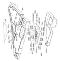
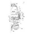
[1−2.扉枠の全体構成]
次に、上記した本体枠3の前面側に開閉自在に設けられる扉枠5について、図17乃至図22を参照して説明する。図17は、扉枠の正面図であり、図18は、扉枠の背面図である。また、図19は、扉枠を右前方から見た斜視図であり、図20は、扉枠を左前方から見た斜視図である。図21は、扉枠の正面から見た分解斜視図であり、図22は、扉枠の背面から見た分解斜視図である。
[1-2. Overall configuration of the door frame]
Next, the door frame 5 provided openably and closably on the front side of the main body frame 3 described above will be described with reference to FIGS. FIG. 17 is a front view of the door frame, and FIG. 18 is a rear view of the door frame. FIG. 19 is a perspective view of the door frame viewed from the front right, and FIG. 20 is a perspective view of the door frame viewed from the left front. FIG. 21 is an exploded perspective view seen from the front of the door frame, and FIG. 22 is an exploded perspective view seen from the back of the door frame.
図17、図18、図21及び図22に示すように、扉枠5は、外形が縦長の矩形状に形成され内周形状が縦長の多角形状とされた遊技窓101を有する扉枠ベースユニット100と、扉枠ベースユニット100の前面で遊技窓101の上部に取付けられる横長のトップランプ電飾ユニット200と、扉枠ベースユニット100の前面で遊技窓101の下部に取付けられる皿ユニット300と、扉枠ベースユニット100の後側に遊技窓101を閉鎖するように取付けられるガラスユニット450と、ガラスユニット450の後側下部を被覆するように扉枠ベースユニット100の後側に取付けられる防犯カバー470とを備えている。この扉枠5における扉枠ベースユニット100には、詳細な説明は後述するが、遊技窓101の左右両側にサイドスピーカ電飾ユニット120を備えており、このサイドスピーカ電飾ユニット120、トップランプ電飾ユニット200、及び皿ユニット300によって、遊技窓101の外周が囲まれた形態となっている。また、扉枠5には、皿ユニット300の正面視左側(開放側)に遊技球の打込操作をするためのハンドル装置400が備えられている。
As shown in FIG. 17, FIG. 18, FIG. 21 and FIG. 22, the door frame 5 is a door frame base unit having a game window 101 whose outer shape is formed in a vertically long rectangular shape and whose inner periphery is in a vertically long polygonal shape. 100, a horizontally long top lamp illumination unit 200 attached to the top of the game window 101 at the front of the door frame base unit 100, and a dish unit 300 attached to the bottom of the game window 101 at the front of the door frame base unit 100; A glass unit 450 attached to the rear side of the door frame base unit 100 to close the game window 101, and a security cover 470 attached to the rear side of the door frame base unit 100 to cover the rear lower portion of the glass unit 450 And have. Although the door frame base unit 100 in the door frame 5 will be described in detail later, the left and right sides of the game window 101 are provided with side speaker electronic decoration units 120. The outer periphery of the game window 101 is surrounded by the decoration unit 200 and the plate unit 300. Further, the door frame 5 is provided with a handle device 400 on the left side (open side) of the plate unit 300 in a front view, for performing a game ball hitting operation.
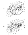
[1−2A.扉枠ベースユニット]
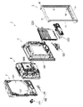
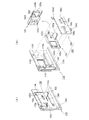
続いて、扉枠5における扉枠ベースユニット100について、主に図23乃至図31を参照して説明する。図23(A)は扉枠ベースユニットの正面斜視図であり、(B)は扉枠ベースユニットの背面斜視図である。図24は、扉枠ベースユニットを分解して前から見た分解斜視図であり、図25は、扉枠ベースユニットを分解して後ろから見た分解斜視図である。また、図26は、扉枠ベースユニットにおけるサイドスピーカ電飾ユニットの左ユニットを分解して前から見た分解斜視図であり、図27は、図26を後ろから見た分解斜視図である。図28は、扉枠ベースユニットにおけるサイドスピーカ電飾ユニットの右ユニットを分解して前から見た分解斜視図であり、図29は、図28を後ろから見た分解斜視図である。更に、図30は、扉枠ベースユニットにおける球送りユニットを分解して示す分解斜視図である。また、図31(A)は扉枠ベースユニットにおけるジョイントユニットの部分を拡大して示す斜視図であり、(B)はジョイントユニットを分解して示す分解斜視図である。
1-2A. Door frame base unit]
Subsequently, the door frame base unit 100 in the door frame 5 will be described mainly with reference to FIG. 23 to FIG. FIG. 23 (A) is a front perspective view of the door frame base unit, and (B) is a rear perspective view of the door frame base unit. FIG. 24 is an exploded perspective view of the door frame base unit as viewed from the front, and FIG. 25 is an exploded perspective view of the door frame base unit as viewed from the rear. FIG. 26 is an exploded perspective view of the left unit of the side speaker illumination unit in the door frame base unit, as viewed from the front, and FIG. 27 is an exploded perspective view of FIG. FIG. 28 is an exploded perspective view of the right unit of the side speaker illumination unit in the door frame base unit, as viewed from the front, and FIG. 29 is an exploded perspective view of FIG. 28 as viewed from the rear. Further, FIG. 30 is an exploded perspective view showing the ball feeding unit in the door frame base unit. FIG. 31 (A) is an enlarged perspective view showing a part of the joint unit in the door frame base unit, and FIG. 31 (B) is an exploded perspective view showing the joint unit in an exploded manner.
図示するように、扉枠ベースユニット100は、外形が縦長の矩形状に形成されると共に、前後方向に貫通し内周が縦長で多角形状に形成された遊技窓101を有した扉枠ベース本体110と、扉枠ベース本体110の前側で遊技窓101の左右両側に固定されるサイドスピーカ電飾ユニット120と、扉枠ベース本体110の後側に固定される金属製で枠状の補強板金140と、補強板金140の後側に固定される横長の装着台160と、装着台160に固定され皿ユニット300から供給される遊技球を一つずつ打球発射装置650へ送る球送りユニット170と、扉枠ベース本体110の後側で補強板金140及び装着台160を介して固定される球送りユニット170の略下側に配置され、ハンドル装置400における操作ハンドル部410の回転操作を打球発射装置650へ伝達させるジョイントユニット180とを主に備えている。
As illustrated, the door frame base unit 100 is a door frame base main body having a game window 101 whose outer shape is formed in a vertically long rectangular shape and which is penetrated in the front-rear direction and whose inner periphery is formed in a vertically long and polygonal shape. 110, a side speaker electronic decoration unit 120 fixed to the left and right sides of the game window 101 on the front side of the door frame base body 110, and a metal frame 140 made of metal fixed to the rear side of the door frame base body 110. And a ball feeding unit 170 for feeding the game balls fixed to the mounting base 160 and supplied from the tray unit 300 to the ball striking device 650 one by one, fixed to the rear side of the reinforcing sheet metal 140, and The operation handle in the handle device 400 is disposed substantially below the ball feed unit 170 fixed on the rear side of the door frame base main body 110 via the reinforcing sheet metal 140 and the mounting table 160. And a joint unit 180 to transmit the rotation operation 410 to hitting the firing device 650 mainly includes.
また、扉枠ベースユニット100は、扉枠ベース本体110の前側で遊技窓101の左下側に固定される左下装飾基板190と、扉枠ベース本体110における皿ユニット300の球抜き経路393と対応する位置に形成された球抜き経路開口112を閉鎖する球抜き経路カバー191と、扉枠ベース本体110の後側で遊技窓101よりも下側に固定される扉装飾駆動基板192と、扉装飾駆動基板192を後方から覆う扉装飾駆動基板カバー193と、扉枠ベース本体110の後側でジョイントユニット180の直上に固定されるハンドル中継端子板194と、遊技窓101の下側で扉枠ベース本体110の後側に形成され左下装飾基板190やハンドル中継端子板194からの配線等を収容可能な配線収容溝110bを後側から閉鎖する配線カバー195と、遊技窓101の左右上部に夫々配置され扉枠ベース本体110の後側に回動可能に軸支される止めレバー196とを備えている。
In addition, the door frame base unit 100 corresponds to the lower left decoration substrate 190 fixed to the lower left side of the game window 101 on the front side of the door frame base main body 110 and the ball removing path 393 of the pan unit 300 in the door frame base main body 110. A ball removal path cover 191 for closing the ball removal path opening 112 formed in the position, a door decoration drive substrate 192 fixed on the rear side of the door frame base body 110 below the game window 101, and a door decoration drive A door decoration drive substrate cover 193 covering the substrate 192 from the rear, a handle relay terminal board 194 fixed immediately above the joint unit 180 on the rear side of the door frame base body 110, and a door frame base body on the lower side of the game window 101 The wiring housing groove 110b formed on the rear side of the housing 110 and capable of containing the wiring from the lower left decorative substrate 190 and the handle relay terminal plate 194 is closed from the rear side. The wiring cover 195, and a stop lever 196 which is pivotally supported on the rear side of the respective arranged door frame base body 110 in the upper left and right of the game window 101.
本例の扉枠ベースユニット100は、合成樹脂からなる矩形状の扉枠ベース本体110の後側に、金属板金をリベット等で組立てた補強板金140が固定されることで、全体の剛性が高められていると共に、トップランプ電飾ユニット200や皿ユニット300等を充分に支持することができる強度を有している。
In the door frame base unit 100 of this example, the overall rigidity is enhanced by fixing a reinforcing sheet metal 140 composed of metal sheet metal by rivets or the like on the rear side of the rectangular door frame base main body 110 made of synthetic resin. It has the strength which can fully support top lamp electric decoration unit 200, dish unit 300 grade, etc. while being carried out.
また、扉枠ベースユニット100における左下装飾基板190は、その前面に複数のLED190aが実装されており、後述する皿ユニット300の左端部を発光装飾させることができるようになっている。一方、扉装飾駆動基板192は、扉枠5に設けられる電飾部品や電気部品(各基板等に実装されたLEDやランプ、スピーカ121,391、ハンドル装置400の操作ハンドル部410内に設けられるスイッチ、貸球ユニット301、操作ボタンユニット370等)からの配線が集約して接続され、その扉装飾駆動基板192からの配線が本体枠3の裏面に取付けられる基板ユニット1100に組み込まれる扉中継基板1102等を介しての賞球払出制御基板1186や遊技盤4に取付けられる主制御基板ボックス624の主制御基板4100(図193を参照)に接続されている。
In addition, a plurality of LEDs 190a are mounted on the front surface of the lower left decorative substrate 190 in the door frame base unit 100 so that the left end portion of the plate unit 300 described later can be lighted and decorated. On the other hand, the door decoration drive board 192 is provided in the electric decoration parts and electric parts (LEDs and lamps mounted on each board etc., the speakers 121 and 391, the operation handle portion 410 of the handle device 400) provided in the door frame 5. A door relay board in which wiring from the switch, ball unit 301, operation button unit 370, etc. is collected and connected, and wiring from the door decoration drive board 192 is mounted on the back surface of the main frame 3 It is connected to a winning ball payout control board 1186 via a 1102 etc. and a main control board 4100 (see FIG. 193) of a main control board box 624 attached to the game board 4.
[1−2A−1.扉枠ベース本体]
まず、扉枠ベースユニット100における扉枠ベース本体110は、図24及び図25等に示すように、合成樹脂によって縦長の額縁状に形成されており、前後方向に貫通し内形が縦長で多角形状の遊技窓101が全体的に上方へオフセットするような形態で形成されている。この扉枠ベース本体110は、遊技窓101によって形成される上辺、及び左右の側辺の幅が、後述する補強板金140の上側補強板金141、軸支側補強板金142、及び開放側補強板金143の幅と略同じ幅とされており、正面視における扉枠ベース本体の大きさに対して、遊技窓101が可及的に大きく形成されている。従って、扉枠5の後側に配置される遊技盤4のより広い範囲を遊技者側から視認できるようになっており、従来のパチンコ機よりも広い遊技領域を容易に形成することができるようになっている。
[1-2A-1. Door frame base body]
First, the door frame base main body 110 in the door frame base unit 100 is formed of a synthetic resin in a vertically elongated frame shape as shown in FIG. 24 and FIG. 25 etc. The game window 101 of a shape is formed in the form which offsets upwards generally. The door frame base main body 110 has an upper side formed by the game window 101 and a width of the left and right side sides, the upper reinforcing sheet metal 141 of the reinforcing sheet metal 140, the axially supporting reinforcing sheet metal 142, and the open side reinforcing sheet metal 143 The game window 101 is formed as large as possible with respect to the size of the door frame base main body in a front view. Therefore, a wider range of the game board 4 disposed behind the door frame 5 can be viewed from the player side, and a game area wider than conventional pachinko machines can be easily formed. It has become.
また、扉枠ベース本体110における遊技窓101よりも下方には、軸支側(正面視で左側)の上部に皿ユニット300の賞球連絡樋343が貫通する賞球通過口111と、賞球通過口111の下方で皿ユニット300における球抜き経路393と対応する位置に形成された球抜き経路開口112と、開放側(正面視で右側)の上部に球送りユニット170を装着するための球送り開口113と、球送り開口113のさらに開放側寄りに後述するシリンダ錠1010が挿通する錠穴114と、球送り開口113の下側でハンドル装置400のカム416が挿通可能なカム挿入開口115とが、扉枠ベース本体110を貫通するように夫々形成されている。
In addition, below the gaming window 101 in the door frame base main body 110, the prize ball passing hole 111 through which the prize ball communication ball 343 of the dish unit 300 penetrates on the upper part of the pivoting side (left side in front view) A ball extraction path opening 112 formed at a position corresponding to the ball extraction path 393 in the pan unit 300 below the passage opening 111 and a ball feed unit 170 for mounting the ball feed unit 170 on the open side (right side in front view) The feed opening 113, a lock hole 114 through which a cylinder lock 1010 described later is inserted near the opening side of the ball feed opening 113, and a cam insertion opening 115 through which the cam 416 of the handle device 400 can be inserted below the ball feed opening 113. Are respectively formed so as to penetrate the door frame base main body 110.
更に、扉枠ベース本体110には、遊技窓101の下端の左右両側に詳細は後述するが防犯カバー470の装着弾性片473を装着するための装着開口部116と、装着開口部116の夫々左右外側に配置され後述するサイドスピーカ電飾ユニット120における左右下側のサイドスピーカ121の後端を逃がすためのスピーカ用開口117とが、貫通するように夫々形成されている。
Furthermore, although the details will be described later on the left and right sides of the lower end of the game window 101, the mounting opening 116 for mounting the mounting elastic piece 473 of the crime prevention cover 470 and the left and right mounting opening 116 respectively. A speaker opening 117 for escaping the rear ends of the side speakers 121 disposed on the outer side and below the left and right lower sides of the side speaker illumination unit 120 described later is respectively formed to penetrate.
また、扉枠ベース本体110の後側には、遊技窓101の内周に略沿って前側へ凹みガラスユニット450の前面外周縁が当接可能なガラスユニット支持段部110aと、遊技窓101の下側で下側補強板金144の前面と略対応する位置に前側へ凹んで形成され配線を収容可能な配線収容溝110bと、カム挿入開口115が開口し前側へ向かって凹みジョイントユニット180を取付けるためのジョイントユニット装着凹部110cとを備えている。
Further, on the rear side of the door frame base main body 110, the front side peripheral edge of the glass unit 450 is indented to the front side along the inner periphery of the game window 101 and the front outer periphery of the glass unit 450 can contact; A wire receiving groove 110b which is formed on the lower side and formed on the front side at a position substantially corresponding to the front surface of the lower reinforcing sheet metal 144 and can receive a wire, and the cam insertion opening 115 opens to attach the concave joint unit 180 toward the front And a joint unit mounting recess 110c.
更に、扉枠ベース本体110の後側には、その下辺から後方へ所定量突出する扉枠突片110d,110eが形成されており、これら扉枠突片110d,110eが、後述する本体枠3の係合溝584,585内に挿入されることで、扉枠5が本体枠3に対して位置決め係止されるようになっている。なお、扉枠突片110dの後方への突出量は、扉枠突片110eの突出量よりも大きくなるように形成されている。
Furthermore, on the rear side of the door frame base main body 110, door frame protrusions 110d and 110e are formed to project backward from the lower side by a predetermined amount, and these door frame protrusions 110d and 110e are the main frame 3 described later. The door frame 5 is positioned and locked with respect to the main body frame 3 by being inserted into the engagement grooves 584 and 585 of the above. The amount of protrusion of the door frame protrusion 110 d to the rear is formed to be larger than the amount of protrusion of the door frame protrusion 110 e.
また、扉枠ベース本体110には、図示するように、その前面上部に、トップランプ電飾ユニット200を固定するための前方へ突出した複数の取付ボス110hが備えられていると共に、その後面に、止めレバー196を回転可能に軸支するための止めレバー取付部110iが備えられている。また、その他に、扉枠ベース本体110には、サイドスピーカ電飾ユニット120、補強板金140、装着台160、皿ユニット300等を固定するための取付ボスや、取付穴が適宜位置に多数形成されている。
Further, as shown in the figure, the door frame base main body 110 is provided with a plurality of mounting bosses 110 h projecting forward for fixing the top lamp illumination unit 200 on the front upper portion thereof and on the rear surface thereof. A stop lever mounting portion 110i for rotatably supporting the stop lever 196 is provided. In addition, in the door frame base main body 110, a large number of mounting bosses for fixing the side speaker illumination unit 120, the reinforcing sheet metal 140, the mounting base 160, the plate unit 300, etc., and a large number of mounting holes are formed. ing.
[1−2A−2.サイドスピーカ電飾ユニット]
続いて、扉枠ベースユニット100におけるサイドスピーカ電飾ユニット120は、扉枠5の前面で遊技窓101の左右両側を電飾(発光装飾)すると共に、遊技窓101の四隅に配置された四つのサイドスピーカ121によって所定の音楽や効果音等を遊技者に対して発することができるものであり、遊技窓の101の軸支側(正面視で左側)に配置される左サイドスピーカ電飾ユニット120Lと、遊技窓101の開放側(正面視で右側)に配置される右サイドスピーカ電飾ユニット120Rとを備えている。このサイドスピーカ電飾ユニット120は、左右のユニット夫々に、縦長の電飾部122と、電飾部122の上下に夫々配置されサイドスピーカ121を有する音響部130とを備え、略左右が対称の構成となっている。
[1-2A-2. Side speaker illumination unit]
Subsequently, the side speaker illumination unit 120 in the door frame base unit 100 illuminates the left and right sides of the game window 101 on the front face of the door frame 5 (light emission decoration) and is disposed at four corners of the game window 101. The left side speaker illumination unit 120L which can emit predetermined music, sound effects, etc. to the player by the side speaker 121, and is arranged on the axis support side (left side in front view) of the gaming window 101. And the right side speaker illumination unit 120R disposed on the open side (right side in front view) of the game window 101. The side speaker illumination unit 120 includes, in each of the left and right units, a vertically long illumination portion 122 and an acoustic portion 130 disposed on the top and bottom of the illumination portion 122 and having a side speaker 121, and the left and right are symmetrical. It is a structure.
詳述すると、サイドスピーカ電飾ユニット120の電飾部122は、図26乃至図29に分解して示すように、縦長の半円柱状で透明なサイド電飾レンズ123と、サイド電飾レンズ123の後側に配置されサイド電飾レンズ123と共に円柱を構成する透明なサイド電飾リフレクタ124と、サイド電飾リフレクタ124の後側に配置されるサイド電飾ベース125と、サイド電飾ベース125の後側に固定されるサイド装飾基板126と、サイド電飾レンズ123及びサイド電飾リフレクタ124の上端及び下端を夫々前側から包み込むように形成されサイド電飾ベース125に取付けられることでサイド電飾レンズ123及びサイド電飾リフレクタ124を支持するサイド電飾フラッシュカバー127と、サイド電飾フラッシュカバー127のフラッシュ開口127aを後側から閉鎖する透光性を有したフラッシュレンズ128と、フラッシュレンズ128の後側に配置されサイド電飾ベース125の前面に支持されるフラッシュ基板129とを備えている。
Specifically, as shown in an exploded manner in FIGS. 26 to 29, the illumination portion 122 of the side speaker illumination unit 120 includes a longitudinally long semi-cylindrical transparent side illumination lens 123 and a side illumination lens 123. Of the transparent side illumination reflector 124 which is disposed on the rear side of the vehicle and which forms a cylinder with the side illumination lens 123, the side illumination decoration base 125 disposed on the rear side of the side illumination reflector 124, and The side decoration lens 126 is formed so as to wrap the upper end and the lower end of the side decoration substrate 126 fixed to the rear side, the side illumination lens 123 and the side illumination reflector 124 from the front side respectively and attached to the side illumination base 125 Side illumination flash cover 127 supporting the 123 and the side illumination reflector 124, and the side illumination flash cover The flash lens 128 has a light-transmitting property to close the flash opening 127a of the lens 27 from the rear side, and the flash substrate 129 disposed on the rear side of the flash lens 128 and supported on the front of the side illumination base 125 .
このサイドスピーカ電飾ユニット120の電飾部122は、サイド電飾基板126の前面に、上下方向に所定間隔で様々な色に発光可能な複数のカラーLED126aと、複数のLED126aの上下に高輝度の白色LED126bとが夫々実装されている。また、サイド電飾リフレクタ124及びサイド電飾ベース125におけるサイド電飾基板126のLED126a,126bと対応する位置には、夫々前後方向に貫通する開口部124a,125aが形成されており、サイド装飾基板126に実装されたLED126a,126bからの光が、サイド電飾ベース125の開口部125a、及びサイド電飾リフレクタ124の開口部124aを通して前方へ照射することができるようになっている。
The electric decoration part 122 of the side speaker electric decoration unit 120 has a plurality of color LEDs 126a capable of emitting various colors at predetermined intervals in the vertical direction on the front surface of the side electric decoration board 126, and high brightness above and below the plurality of LEDs 126a The white LEDs 126b are mounted respectively. In addition, openings 124a and 125a penetrating in the front and rear direction are formed at positions corresponding to the LEDs 126a and 126b of the side electric decoration substrate 126 in the side electric decoration reflector 124 and the side electric decoration base 125, respectively. The light from the LEDs 126 a and 126 b mounted on the light source 126 can be emitted forward through the opening 125 a of the side illumination base 125 and the opening 124 a of the side illumination reflector 124.
また、電飾部122では、サイド電飾レンズ123とサイド電飾リフレクタ124の透明な円柱内の内側に、サイド電飾レンズ123の内周全体とサイド電飾リフレクタ124の内周の一部にかかるように断面略U字状のサイドレンズシート123aが配置されている。このサイドレンズシート123aは、透過光や反射光を、パール状或いは彩光状に見せる公知の光学シートにより形成されおり、遊技者側から見ると、このサイドレンズシート123aによって、サイド電飾レンズ123及びサイド電飾リフレクタ124により形成された透明な円柱(パイプ)内に、あたかも蛍光管(蛍光灯)が配置されたような外観を呈することができるようになっている。
In the electric decoration part 122, inside the transparent cylinder of the side electric decoration lens 123 and the side electric decoration reflector 124, the entire inner circumference of the side electric decoration lens 123 and a part of the inner circumference of the side electric decoration reflector 124 As described above, the side lens sheet 123a having a substantially U-shaped cross section is disposed. The side lens sheet 123a is formed of a known optical sheet that makes transmitted light or reflected light appear pearly or colorful, and when viewed from the player side, the side illumination lens 123 is formed by the side lens sheet 123a. And in the transparent cylinder (pipe) formed of the side illumination reflector 124, it can be made to take on the appearance as if a fluorescent tube (fluorescent lamp) was arrange | positioned.
更に、電飾部122では、サイド電飾リフレクタ124に、サイド装飾基板126の複数のLED126aと対応して形成された複数の開口部124aを、上下方向に三つのグループに分割する分割壁124bを備えており、この分割壁124bによって所定のLED126aからの光が他のグループへ進入するのを抑制するようにしている。つまり、分割壁124bによって、サイド電飾レンズ123及びサイド電飾リフレクタ124によって形成される蛍光管を上中下の三つに明確に分割することができるようになっている。従って、サイド装飾基板126に実装された複数のLED126aを適宜発光させることで、蛍光管を全体的あるいは部分的に発光させたり、上中下の各部分毎に様々な色に発光させたりすることができるようになっている。
Furthermore, in the electric decoration part 122, the dividing wall 124b which divides the several opening part 124a formed corresponding to several LED126a of the side decoration board | substrate 126 in the side electric decoration reflector 124 into three groups in an up-down direction The dividing wall 124b is provided to prevent the light from a predetermined LED 126a from entering another group. That is, by the dividing wall 124b, the fluorescent tube formed by the side illumination lens 123 and the side illumination reflector 124 can be clearly divided into three, that is, the upper middle, the lower and the lower one. Therefore, by causing the plurality of LEDs 126a mounted on the side decoration substrate 126 to emit light appropriately, the fluorescent tube is caused to emit light entirely or partially, or light is emitted in various colors for each of the upper, middle, and lower portions. It is possible to
また、サイド電飾リフレクタ124には、サイド装飾基板126における上下のLED126bと対応した位置に、前側から凹んだレンズ凹部124cが形成されており、このレンズ凹部124cに前側から半円形状のサブレンズ122a(図28及び図29を参照)が挿入されるようになっている。本例の電飾部122は、このサブレンズ122a及びLED126bにより、LED126aを発光させる前に、LED126bのみを強く発光させることで、サイド電飾レンズ123及びサイド電飾リフレクタ124によって形成される蛍光管をあたかも本物の蛍光灯のように、両端のみが光ってから点灯するような発光演出をすることができるようになっている。
Further, in the side illumination reflector 124, a lens recess 124c recessed from the front side is formed at a position corresponding to the upper and lower LEDs 126b in the side decoration substrate 126, and a semicircular sub lens from the front side is formed in the lens recess 124c. 122a (see FIG. 28 and FIG. 29) is inserted. The electric decoration part 122 of this example is a fluorescent tube formed by the side electric decoration lens 123 and the side electric decoration reflector 124 by making only the LED 126 b emit light strongly before making the LED 126 a emit light by the sub lens 122 a and the LED 126 b. As if it were a real fluorescent lamp, it is possible to produce a light-emitting effect in which only both ends light up and then light up.
更に、電飾部122は、サイド電飾フラッシュカバー127の後側に支持されるフラッシュ基板129の前面に強い光を発光可能なフラッシュライト129a(例えば、超高輝度白色LED等)が取付けられており、このフラッシュライト129aを発光させることで、閃光(フラッシュ)を遊技者側へ照射させることができるようになっている。
Furthermore, in the electric decoration part 122, a flash light 129a (for example, super high brightness white LED etc.) capable of emitting strong light is attached to the front surface of the flash substrate 129 supported on the rear side of the side electric decoration flash cover 127 By making the flash light 129a emit light, it is possible to emit a flash to the player side.
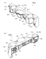
サイドスピーカ電飾ユニット120の音響部130は、最前部に配置され略円形のスピーカ開口131aを有したスピーカ飾り131と、スピーカ飾り131のスピーカ開口131aを後側から閉鎖するパンチングメタルからなる略円盤状のスピーカカバー132と、スピーカカバー132の後側に配置されスピーカ飾り131と協働してスピーカカバーを狭持し円形のスピーカ前支持口133aを有した飾りスペーサ133と、飾りスペーサ133のスピーカ前支持口133aを後側から閉鎖するように配置されるサイドスピーカ121と、サイドスピーカ121の外周に後側から嵌合するスピーカ嵌合口134aを有した裏押え部材134とを主に備えている。
The sound unit 130 of the side speaker illumination unit 120 is a substantially disc made of a speaker ornament 131 disposed at the foremost portion and having a substantially circular speaker opening 131a, and a punching metal closing the speaker opening 131a of the speaker ornament 131 from the rear side. Speaker cover 132, a decorative spacer 133 disposed on the rear side of the speaker cover 132, in cooperation with the speaker decoration 131 to sandwich the speaker cover and having a circular speaker front support opening 133a, and a speaker of the decoration spacer 133 Mainly provided with a side speaker 121 arranged to close the front support port 133a from the rear side, and a back pressing member 134 having a speaker fitting opening 134a fitted to the outer periphery of the side speaker 121 from the rear side .
この音響部130は、図示するように、スピーカ飾り131や飾りスペーサ133、及び裏押え部材134の形状が、取付けられる位置に応じて異なる形状とされている。具体的には、図26及び図27に示すように、正面視で左上の音響部130では、スピーカ飾り131が円筒状に形成された上で左側から外方へ延び出す装飾部131bを有し、飾りスペーサ133がスピーカ飾り131内へ挿入可能な円筒状とされると共に、裏押え部材134にはスピーカ飾り131の装飾部131bと組になる裏押え装飾部134bが形成されている。なお、左上の音響部130には、裏押え部材134の裏押え装飾部134bの上部に配置され補強板金140における上軸支部146の軸ピン145よりも下側を覆うヒンジカバー135を更に備えている。また、正面視で左下の音響部130では、スピーカ飾り131が装飾部131bを有した板状に形成されると共に、飾りスペーサ133がスピーカ飾り131の装飾部131bと組になるスペーサ装飾部133bを有した板状に形成され、裏押え部材134がリング状に形成されている。
As shown in the figure, in the sound unit 130, the shapes of the speaker decoration 131, the decoration spacer 133, and the back pressing member 134 are different depending on the mounting position. Specifically, as shown in FIGS. 26 and 27, the sound unit 130 at the upper left in the front view has the speaker decoration 131 formed in a cylindrical shape, and has a decoration portion 131b extending outward from the left side The decorative spacer 133 is formed in a cylindrical shape that can be inserted into the speaker decoration 131, and the back pressing member 134 is formed with a back pressing decoration part 134b to be combined with the decoration part 131b of the speaker decoration 131. The upper left acoustic portion 130 further includes a hinge cover 135 disposed above the back pressing decorative portion 134 b of the back pressing member 134 and covering the lower side than the shaft pin 145 of the upper shaft support portion 146 of the reinforcing sheet metal 140 There is. Moreover, in the acoustic unit 130 at the lower left in a front view, the speaker decoration 131 is formed in a plate shape having the decoration part 131 b, and the spacer decoration part 133 b in which the decoration spacer 133 is paired with the decoration part 131 b of the speaker decoration 131 The back holding member 134 is formed in a ring shape.
一方、図28及び図29に示すように、正面視で右上の音響部130では、スピーカ飾り131が円筒状に形成されると共に、飾りスペーサ133と裏押え部材134とがスピーカ飾り131内へ挿入可能な円筒状に形成されている。また、正面視で右下の音響部130では、スピーカ飾り131が円環状に形成された上で、飾りスペーサ133がスピーカ飾り131の後面と当接するスペーサ装飾部133bを有した平板状に形成されると共に、裏押え部材134がリング状に形成されている。なお、右下の音響部130では、裏押え部材134の更に後側に、裏押え部材134を前側から挿通固定可能な貫通する裏押え部材固定口136aを有した飾りベース136を更に備えている。
On the other hand, as shown in FIG. 28 and FIG. 29, in the acoustic section 130 at the upper right in front view, the speaker decoration 131 is formed in a cylindrical shape, and the decoration spacer 133 and the back pressing member 134 are inserted into the speaker decoration 131 It is formed in a possible cylindrical shape. Further, in the acoustic unit 130 at the lower right in front view, the speaker decoration 131 is formed in an annular shape, and the decoration spacer 133 is formed in a flat plate shape having a spacer decoration portion 133b that contacts the rear surface of the speaker decoration 131 The back holding member 134 is formed in a ring shape. The sound unit 130 at the lower right is further provided with a decorative base 136 on the further rear side of the back pressing member 134, having a back pressing member fixing port 136a through which the back pressing member 134 can be inserted and fixed from the front. .
本例のサイドスピーカ電飾ユニット120における四つのサイドスピーカ121は、図示するように、遊技窓101の上下左右の四隅に配置されており、蓋然的に、遊技する遊技者の頭部に対しても上下左右の位置に配置されるようになっているので、各サイドスピーカ121に対して独立した音響信号(例えば、2chステレオ信号、4chステレオ信号、後述する下部スピーカ391を加えた2.1chサラウンド信号或いは4.1chサラウンド信号、等)を送ることで、従来よりも臨場感のある音響効果(音響演出)を提示することができるようになっている。なお、本例のサイドスピーカ121は、主に中音域から高音域を担当し、下部スピーカ391は、低音域を担当するものとなっている。
The four side speakers 121 in the side speaker illumination unit 120 of the present example are disposed at the four corners of the game window 101, as shown in the figure, and for the head of the player who is likely to play the game Are arranged at the top, bottom, left, and right positions, so 2.1ch surround sound signals (for example, 2ch stereo signal, 4ch stereo signal, and a lower speaker 391 described later added to each side speaker 121 are added) By sending a signal or a 4.1 ch surround signal, etc., it is possible to present a more realistic sound effect (sound effect) than ever before. In addition, the side speaker 121 of this example mainly takes charge of a mid range to a high range, and the lower speaker 391 takes charge of a low range.
[1−2A−3.補強板金]
次に、扉枠ベースユニット100における補強板金140は、主に図24及び図25に示すように、扉枠ベース本体110の上辺部裏面に沿って取付けられる上側補強板金141と、扉枠ベース本体110の軸支側辺部裏面に沿って取付けられる軸支側補強板金142と、扉枠ベース本体110の開放側辺部裏面に沿って取付けられる開放側補強板金143と、扉枠ベース本体110の遊技窓101の下辺裏面に沿って取付けられる下側補強板金144と、が相互にビス等で締着されて方形状に形成されている。
[1-2A-3. Reinforcing sheet metal]
Next, as shown mainly in FIGS. 24 and 25, the reinforcing sheet metal 140 in the door frame base unit 100 is an upper reinforcing sheet metal 141 attached along the upper side back surface of the door frame base main body 110; A pivot support side reinforcing sheet metal 142 mounted along the back surface of the support side 110 of the support side, an open side reinforcement sheet metal 143 mounted along the back side of the open side end portion of the door frame base main body 110, and the door frame base main body 110 A lower reinforcing metal plate 144 attached along the lower side back surface of the game window 101 is mutually tightened with a screw or the like to form a square shape.
この補強板金140は、図24に示すように、軸支側補強板金142の上下端部に、その上面に上下方向に摺動自在に設けられる軸ピン145を有する上軸支部146と、その下面に軸ピン147(図18を参照)を有する下軸支部148と、が一体的に形成されている。そして、上下の軸ピン145,147が本体枠3の軸支側上下に形成される上軸支金具503及び下軸支金具509に軸支されることにより、扉枠5が本体枠3に対して開閉自在に設けられるものである。
As shown in FIG. 24, the reinforcing sheet metal 140 has an upper shaft supporting portion 146 having a shaft pin 145 slidably provided in the upper and lower directions on the upper surface and the lower surface thereof at the upper and lower end portions of the shaft supporting side reinforcing sheet metal 142 And a lower shaft support portion 148 having a shaft pin 147 (see FIG. 18). The upper and lower shaft pins 145 and 147 are pivotally supported by the upper shaft support bracket 503 and the lower shaft support bracket 509 formed on the upper and lower shaft support sides of the main body frame 3, whereby the door frame 5 is mounted to the main body frame 3. It is provided to be openable and closable.
また、補強板金140の下側補強板金144は、所定幅を有して扉枠ベース本体110の横幅寸法と略同じ長さに形成され、その長辺の両端縁のうち下方長辺端縁が後方に向って折曲した下折曲突片149となっており(図25を参照)、上方長辺端縁の両側部が後方に向って折曲した上折曲突片150となっているものの、その両側部の上折曲突片150に挟まれる部分が垂直方向に延設される垂直折曲突片151となっている。下折曲突片149の突出量はあまり大きくなく、この下折曲突片149が溝部や凹部と係合して凹凸係合をなすものではなく、強度を高めるために形成されているのに対し、両側部の上折曲突片150の突出量は下折曲突片149の突出量よりもやや大きく下方からの不正具の侵入を多少防止するが、むしろ、本実施形態における下側補強板金144の構成で最も特徴的な構成は、垂直折曲突片151である。
Further, the lower reinforcing sheet metal 144 of the reinforcing sheet metal 140 has a predetermined width and is formed to have substantially the same length as the lateral width dimension of the door frame base main body 110, and the lower long side end edges It is a lower bent piece 149 which is bent backward (see FIG. 25), and an upper bent piece 150 which is bent backward at both sides of the upper long side edge is formed. However, a portion sandwiched by the upper bending projections 150 on both sides thereof is a vertical bending projection 151 extended in the vertical direction. Although the amount of protrusion of the lower bent protrusion 149 is not very large, and the lower bent protrusion 149 is not engaged with the groove portion or the recessed portion to form the concavo-convex engagement, and is formed to enhance the strength. On the other hand, although the amount of protrusion of the upper bending protrusions 150 on both sides is slightly larger than the amount of protrusion of the lower bending protrusions 149, the intrusion of the incorrect tool from the lower part is somewhat prevented, but rather the lower reinforcement in this embodiment. The most characteristic configuration of the configuration of the sheet metal 144 is the vertical bending projection 151.
この垂直折曲突片151は、その上端縁形状が後述するガラスユニット450のユニット枠451の下端形状に合致するように凹状に形成され、ガラスユニット450を扉枠5の裏面側に固定したときに、垂直折曲突片151の上端片がガラスユニット450のユニット枠451における幅方向(前後方向)の略中央の外周に沿って形成される係合溝451cに係合するようになっている。なお、下側補強板金144には、扉枠ベース本体110に形成された賞球通過口111の底面を除く外周を保護する賞球通過口被覆部152が形成されている。
The vertically bent projecting piece 151 is formed in a concave shape so that the upper end edge shape matches the lower end shape of the unit frame 451 of the glass unit 450 described later, and when the glass unit 450 is fixed to the back surface side of the door frame 5 The upper end piece of the vertically bent projecting piece 151 is engaged with an engagement groove 451 c formed along the outer periphery of the unit frame 451 of the glass unit 450 in the substantially central portion in the width direction (front-back direction) . In the lower reinforcing sheet metal 144, a prize ball passage port covering portion 152 is formed which protects the outer periphery of the bottom surface of the prize ball passage hole 111 formed in the door frame base main body 110.
また、補強板金140の開放側補強板金143には、上側補強板金141と下側補強板金144との間の長辺の両側に、後方へ向かって屈曲された開放側外折曲突片153及び開放側内折曲突片154が夫々形成されており、開放側外折曲突片153よりも開放側内折曲突片154の方が後方へ長く延び出したように形成されている。また、上側補強板金141には、その長辺の両側に後方へ向かって屈曲された屈曲突片155,156が夫々形成されている。更に、軸支側補強板金142には、その長辺の外側端に後方へ延び出した軸支側L字状折曲突片157が形成されている。また、開放側補強板金143の後側下部には、後述する錠装置1000の扉枠用フック部1041と当接するフックカバー158が取付けられている。
In addition, the open side reinforcing sheet metal 143 of the reinforcing sheet metal 140 includes an open side outer bending projection 153 bent toward the rear on both sides of the long side between the upper reinforcing sheet metal 141 and the lower reinforcing sheet metal 144 and The open side inner bent pieces 154 are respectively formed, and the open side inner bent pieces 154 are formed to extend rearward more than the open side outer bent pieces 153. Further, on the upper reinforcing sheet metal 141, bent projecting pieces 155 and 156 which are bent backward on both sides of the long side are respectively formed. Furthermore, a bearing side L-shaped bent projecting piece 157 is formed on the bearing side reinforcing sheet metal 142 so as to extend rearward at the outer end of the long side thereof. In addition, a hook cover 158 that is in contact with a door frame hook portion 1041 of the lock device 1000, which will be described later, is attached to the rear lower portion of the open side reinforcing sheet metal 143.
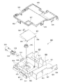
[1−2A−4.装着台・球送りユニット]
次に、扉枠ベースユニット100における装着台160及び球送りユニット170について説明する。まず、装着台160は、図18、図24、及び図25に示すように、扉枠ベースユニット100の板部裏面の上半分を覆うように取付けられ、防犯カバー470と同様に透明な合成樹脂によって前方が開放した横長直方体状に形成されている。この装着台160は、発射レール515から発射された球をスムーズに遊技盤4に導くために、扉枠5を閉めたときに装着台160の後面と本体枠3の板部511とによって発射レール515を挟持するように形成されており、装着台160の後面に球飛送誘導面161が形成されている。ところで、本実施形態に係る装着台160には、その軸支側上部に下側補強板金144に形成される賞球通過口被覆部152の後方突出部を貫通させる賞球通過口用開口162が形成されており、その開放側下部に球送りユニット170を取付ける球送りユニット取付凹部163が形成されている。この球送りユニット取付凹部163から斜め方向の領域が球飛送誘導面161となっている。
[1-2A-4. Mounting stand, ball feed unit]
Next, the mounting base 160 and the ball feeding unit 170 in the door frame base unit 100 will be described. First, the mounting table 160 is attached to cover the upper half of the rear surface of the plate portion of the door frame base unit 100 as shown in FIGS. 18, 24 and 25, and is transparent synthetic resin like the crime prevention cover 470. It is formed in the shape of a long rectangular parallelepiped whose front is open. In order to smoothly guide the balls fired from the firing rail 515 to the game board 4, the mounting platform 160 fires by the rear surface of the mounting platform 160 and the plate portion 511 of the main body frame 3 when the door frame 5 is closed. A ball flight guiding surface 161 is formed on the rear surface of the mounting table 160. By the way, in the mounting table 160 according to the present embodiment, an opening 162 for the prize ball passage opening through which the rearward projecting portion of the prize ball passage hole covering portion 152 formed on the lower reinforcing sheet metal 144 is penetrated It is formed, and a ball feed unit mounting recess 163 for attaching the ball feed unit 170 is formed at the lower side on the open side. An area in an oblique direction from the ball feeding unit mounting recess 163 is a ball flight guiding surface 161.
また、装着台160の中程下部には、後述する球抜き経路カバー191、扉装飾駆動基板192及び扉装飾駆動基板カバー193を取り外す際に指を入れることができる蓋用切欠き164が形成されていると共に、装着台160の上辺の一部には、垂直に立設される立壁165が形成されている。この立壁165は、図18に示すように、防犯カバー470を取付けたときに、防犯カバー470の前面と当接して防犯カバー470の下部が前方に移動しないように規制するためのものである。
Further, in the middle lower part of the mounting table 160, a cover notch 164 for inserting a finger when removing the ball removal path cover 191, the door decoration drive board 192 and the door decoration drive board cover 193 described later is formed. In addition, on a part of the upper side of the mounting table 160, a standing wall 165 which is vertically provided is formed. As shown in FIG. 18, when the security cover 470 is attached, the standing wall 165 abuts against the front surface of the security cover 470 to restrict the lower part of the security cover 470 from moving forward.
更に、この装着台160には、上述した球飛送誘導面161の下方から賞球通過口用開口162にかけて斜め状に後方へ向かって突設された防犯突片166を備えている。この防犯突片166は、前述したように、本体枠3の板部511に形成される防犯空間586との間で、扉枠5と本体枠3との下側辺部における内側の突条及び係合部を構成するものである。
Further, the mounting table 160 is provided with a security projection 166 which is provided obliquely rearward from the lower side of the above-mentioned ball flight guiding surface 161 to the opening for the ball passing hole 162. As described above, the crime prevention projection 166 and the crime prevention space 586 formed in the plate portion 511 of the main body frame 3 are provided with the inner ridges at the lower side portions of the door frame 5 and the main body frame 3 and It constitutes an engaging portion.
一方、球送りユニット170は、図30に示すように、球送りユニット取付凹部163に固定される箱状の本体部171と、本体部171の支持軸171aに回動可能に軸支された球送り部材172と、球送り部材172の球受部を上方へ回動させると共に回転可能に球送り部材172に軸支された錘173とを備えている。この球送りユニット170は、球送り部材172が後述する打球発射装置650の打球槌687の往復動差に対応して揺動することで、皿ユニット300の第三傾斜面311cの流下端にある球を、本体部171に形成された打球供給口171bを通して発射レール515の発射位置に1個ずつ供給するものである。
On the other hand, as shown in FIG. 30, the ball feeding unit 170 has a box-shaped main body 171 fixed to the ball feeding unit mounting recess 163 and a ball pivotally supported by a support shaft 171a of the main body 171. A feed member 172, and a weight 173 pivotally supported by the ball feed member 172 while rotating the ball receiving portion of the ball feed member 172 upward are provided. The ball feed unit 170 is located at the lower end of the third inclined surface 311 c of the pan unit 300 by swinging the ball feed member 172 in correspondence with the reciprocation differential of the hitting ball 687 of the hitting and firing device 650 described later. The balls are supplied one by one to the launch position of the launch rail 515 through the strike delivery port 171 b formed in the main body 171.
なお、図中の符号174は、Eリングであり、本体部171の支持軸171aから球送り部材172が抜けるのを防止したり、球送り部材172から錘173が抜けるのを防止したりするものである。
In the figure, reference numeral 174 denotes an E ring, which prevents the ball feeding member 172 from coming off from the support shaft 171a of the main body 171, and prevents the weight 173 from coming off from the ball feeding member 172. It is.
[1−2A−5.ジョイントユニット]
続いて、扉枠ベースユニット100におけるジョイントユニット180について説明する。ジョイントユニット180は、図31に示すように、扉枠ベース本体110のジョイントユニット装着凹部110cの内部に収納されて横方向にスライド可能なスライド体182と、スライド体182が収納された状態でジョイントユニット装着凹部110cの前面を被覆するカバー体184とから構成されている。
[1-2A-5. Joint unit]
Subsequently, the joint unit 180 in the door frame base unit 100 will be described. As shown in FIG. 31, the joint unit 180 is housed in the joint unit mounting recess 110c of the door frame base main body 110 and can slide in the lateral direction in the state where the slide body 182 and the slide body 182 are accommodated. It is comprised from the cover body 184 which covers the front surface of the unit mounting recessed part 110c.
扉枠ベース本体110のジョイントユニット装着凹部110cは、前面が開放した直方体の箱状に形成され、その後面にカム挿入開口115が開設されている。また、ジョイントユニット装着凹部110cの一つの略対角線状に位置する隅部には、ジョイントユニット180のカバー体184を固定するための一対の取付穴110fが形成されている。更に、ジョイントユニット装着凹部110cの内側面の上辺及び底辺には、スライド体182の上下辺の外側面と当接してスライド体182がスムーズに移動できるようにするための円弧状の当接凸部110g(図31(B)では下辺の当接凸部110gだけを図示し、上辺の当接凸部110gは図示省略されている。)が突設されている。
The joint unit mounting recess 110c of the door frame base main body 110 is formed in a rectangular box shape whose front face is open, and a cam insertion opening 115 is opened on the rear face. Further, a pair of attachment holes 110 f for fixing the cover body 184 of the joint unit 180 is formed at one substantially diagonal corner of the joint unit attachment recess 110 c. Furthermore, on the upper and lower sides of the inner surface of the joint unit mounting recess 110c, arc-shaped contact protrusions for contacting the outer surfaces of the upper and lower sides of the slide body 182 to allow the slide body 182 to move smoothly. In FIG. 31 (B), only the contact convex portion 110g on the lower side is shown, and the contact convex portion 110g on the upper side is not shown.
一方、ジョイントユニット180のスライド体182は、ジョイントユニット装着凹部110cとカバー体184とによって形成される空間内に左右方向に移動可能に収納されるように、ジョイントユニット装着凹部110cよりも小さな後面が開放した直方体の箱状に形成され、その後面壁には、後方へ所定量突出し略水平方向に並んで配置された二つの案内突起182aと、背面視で右側の案内突起182aの下側に配置され後方へ突出する板状のスライド突片183と、二つの案内突起182aの間でスライド突片183よりも背面視で左側に後述するハンドル装置400の配線通し筒部428が貫通するように穿設された矩形状の筒部材貫通開口182bとを備えている。このスライド体182のスライド突片183は、スライド時の進行方向(背面視で右方向)が斜めにカットされた傾斜辺183aとなっている。また、スライド体182の前面壁には、ハンドル装置400における回転軸415の先端部に固定されるカム416が収納されるカム係合凹部182cがリブによってコ字形状に形成されている。そして、カム係合凹部182cを形成するリブの一部の垂直部分がカム係合凹部182c内に突出するように円弧状のリブとして形成され、その部分がカム416と当接するカム当接部182dとなっている。
On the other hand, the slide body 182 of the joint unit 180 has a rear surface smaller than the joint unit attachment recess 110 c so as to be accommodated movably in the left and right direction in the space formed by the joint unit attachment recess 110 c and the cover member 184. It is formed in an open rectangular box shape, and is disposed on the rear surface wall below the two guide projections 182a which project rearward by a predetermined amount and are arranged in a substantially horizontal direction and the guide projections 182a on the right side in rear view A plate-like slide protrusion 183 protruding rearward and a wire through cylinder portion 428 of a handle device 400 described later are pierced on the left side in a rear view with respect to the slide protrusion 183 between the two guide protrusions 182a. And a rectangular cylinder member through opening 182b. The slide projecting piece 183 of the slide body 182 has an inclined side 183 a which is obliquely cut in the traveling direction (right direction in rear view) at the time of sliding. Further, on the front wall of the slide body 182, a cam engaging concave portion 182c in which a cam 416 fixed to the tip end portion of the rotating shaft 415 in the handle device 400 is accommodated is formed in a U shape by a rib. And, a cam contact portion 182d is formed as an arc-shaped rib so that a portion of the vertical part of the rib forming the cam engagement recess 182c protrudes into the cam engagement recess 182c and the portion abuts against the cam 416 It has become.
また、ジョイントユニット180のカバー体184は、前面が開放した直方体の箱状に形成され、その前面にスライド体182の前面に突設される円筒ボス状の案内突起182aが挿入されてスライド体182の移動を案内する横長穴状の2つの案内横穴194aと、スライド体182の前面に突設されるスライド突片183が挿通される挿通横穴184bと、操作ハンドル部410の後握り部材413の後端に取付けられてカム挿入開口115から挿入される配線通し筒部428の後端部が臨む配線開口184cと、ジョイントユニット装着凹部110cの取付穴110fと対応する位置から外方へ突出するように形成された取付穴184dとを備えている。この取付穴184dを介してジョイントユニット装着凹部110cの取付穴110fへ所定のビス(図示しない)を止着することで、カバー体184をジョイントユニット装着凹部110cに取付けることができるようになっている。
Further, the cover body 184 of the joint unit 180 is formed in a rectangular box shape whose front face is open, and a cylindrical boss-like guide projection 182a which is provided on the front face of the slide body 182 is inserted in the front face thereof. Of the two horizontal guide holes 194a for guiding the movement of the slide, the insertion horizontal hole 184b through which the slide projection 183 provided on the front surface of the slide body 182 is inserted, and the rear of the rear grip member 413 of the operation handle portion 410. It projects outward from the position corresponding to the wiring opening 184c which the rear end of the wiring through cylinder 428 attached to the end and inserted from the cam insertion opening 115 faces and the mounting hole 110f of the joint unit mounting recess 110c. And a formed mounting hole 184d. The cover body 184 can be attached to the joint unit attachment recess 110c by fixing a predetermined screw (not shown) to the attachment hole 110f of the joint unit attachment recess 110c through the attachment hole 184d. .
ジョイントユニット180のスライド体182とカバー体184とをジョイントユニット装着凹部110cに組み付けるには、ジョイントユニット装着凹部110cにスライド体182を収納し、その状態でカバー体184を前方から被覆する。被覆する際には、案内突起182aが案内横穴194aに、スライド突片183が挿通横穴184bに、夫々挿通するようにする。そして、被覆した後には、取付穴184dを介して取付穴110fにビスで螺着することにより、スライド体182を内部に収納した状態となってジョイントユニット180の組み付けが終了する。
In order to assemble the slide body 182 and the cover body 184 of the joint unit 180 into the joint unit attachment recess 110c, the slide body 182 is accommodated in the joint unit attachment recess 110c, and the cover body 184 is covered from the front in that state. At the time of coating, the guide projection 182a is inserted into the guide lateral hole 194a, and the slide protrusion 183 is inserted into the insertion lateral hole 184b. After coating, the slide body 182 is housed inside by screwing the mounting hole 110 f with a screw via the mounting hole 184 d, and the assembly of the joint unit 180 is completed.
[1−2B.トップランプ電飾ユニット]
次に、扉枠5におけるトップランプ電飾ユニット200について、主に図32乃至図39を参照して説明する。図32(A)はトップランプ電飾ユニットの正面斜視図であり、(B)はトップランプ電飾ユニットの背面斜視図であり、図33はトップランプ電飾ユニットを斜め前下から示す斜視図である。図34(A)はトップランプ電飾ユニットを主な構成毎に分解して前から示す分解斜視図であり、(B)は(A)を後から示す分解斜視図である。また、図35はトップランプ電飾ユニットにおけるトップランプリフレクタユニットを分解してトップランプベースと共に前から示す分解斜視図であり、図36は図35を後から示す分解斜視図である。更に、図37はトップランプ電飾ユニットにおける左回転灯を分解して示す分解斜視図であり、図38はトップランプ電飾ユニットにおける右回転灯を分解して示す分解斜視図であり、また、図39はトップランプ電飾ユニットにおける中央回転灯を分解して示す分解斜視図である。
[1-2 B. Top lamp lighting unit]
Next, the top lamp illumination unit 200 in the door frame 5 will be described mainly with reference to FIG. 32 to FIG. 32 (A) is a front perspective view of the top lamp illumination unit, FIG. 32 (B) is a rear perspective view of the top lamp illumination unit, and FIG. 33 is a perspective view showing the top lamp illumination unit from diagonally front and bottom It is. FIG. 34 (A) is an exploded perspective view showing the top lamp illumination unit disassembled for each main configuration and shown from the front, and FIG. 34 (B) is an exploded perspective view showing (A) later. FIG. 35 is an exploded perspective view showing the top lamp reflector unit in the top lamp illumination unit disassembled and shown together with the top lamp base, and FIG. 36 is an exploded perspective view showing FIG. Furthermore, FIG. 37 is an exploded perspective view showing the left rotating lamp in the top lamp illumination unit disassembled, and FIG. 38 is an exploded perspective view showing the right rotating lamp in the top lamp illumination unit disassembled, FIG. 39 is an exploded perspective view showing the central rotation lamp in the top lamp illumination unit.
本実施形態の扉枠5におけるトップランプ電飾ユニット200は、図33にも示すように、左右方向に並んだ三つの回転灯244,264,284(所謂、パトライト(登録商標))を備えており、それら回転灯244,264,284の大きさは正面視で左側から順に大きなものが配置されている。このトップランプ電飾ユニット200は、横長で箱状のトップランプベース210と、トップランプベース210の前面に固定されると共にトップランプベース210を挟んで扉枠べースユニット100の前面上部に固定されるトップランプリフレクタユニット220と、トップランプリフレクタユニット220の前面に取付けられる左回転灯ユニット240、右回転灯ユニット260、及び中央回転灯ユニット280と、左回転灯ユニット240、右回転灯ユニット260、及び中央回転灯ユニット280の前面を夫々覆いトップランプリフレクタユニット220に取付けられる回転灯カバー201,202,203と、トップランプリフレクタユニットの略中央下面を覆うリフレクタインナ204と、を主に備えている(図34を参照)。
The top lamp illumination unit 200 in the door frame 5 of the present embodiment is provided with three rotary lights 244, 264, 284 (so-called Patlite (registered trademark)) aligned in the left-right direction, as also shown in FIG. The sizes of these rotary lights 244, 264, 284 are arranged in order from the left in front view. The top lamp illumination unit 200 is fixed to the front of the box-like top lamp base 210 and to the front of the top lamp base 210 and is fixed to the top front of the door frame base unit 100 with the top lamp base 210 in between. Top lamp reflector unit 220, left turn light unit 240 attached to the front of top lamp reflector unit 220, right turn light unit 260, center turn light unit 280, left turn light unit 240, right turn light unit 260, Mainly provided with rotary lamp covers 201, 202 and 203 attached to the top lamp reflector unit 220 respectively covering the front of the central rotary lamp unit 280, and a reflector inner 204 covering the lower surface of the top lamp reflector unit approximately at the center ( See Figure 34)
また、トップランプ電飾ユニット200には、トップランプベース210の前側右に固定されるトップランプ電源基板205と、トップランプベース210の後側に固定される二つのトップランプ装飾駆動基板206とを更に備えている。このトップランプ電源基板205は、トップランプ電飾ユニット200内の各基板224,226,231やLED244a,266a,231a、各回転灯ユニット240,260,280のモータ245,265,285や各基板248,268,288,296のLED、後述するガラスユニット450のLED453a等へ電源基板1136(後述する)からの電源を中継して供給するためのものである。また、トップランプ装飾駆動基板206は、トップランプリフレクタユニット220内のLEDや、中央回転灯ユニット280内のLED、及び各回転灯ユニット240,260,280のモータ245,265,285等の発光や駆動を、後述する周辺基板4010(周辺制御基板4140、図193を参照)からの制御信号に基いて駆動させるためのものである。
The top lamp illumination unit 200 further includes a top lamp power supply substrate 205 fixed to the front right of the top lamp base 210, and two top lamp decoration driving substrates 206 fixed to the rear side of the top lamp base 210. It is further equipped. The top lamp power supply substrate 205 includes the substrates 224, 226 and 231 and the LEDs 244a, 266a and 231a in the top lamp illumination unit 200, the motors 245, 265 and 285 of the rotary light units 240, 260 and 280, and the substrates 248. , 268, 288, and 296, and an LED 453a of a glass unit 450, which will be described later, is relayed to supply power from a power supply substrate 1136 (described later). In addition, the top lamp decoration drive substrate 206 emits light from the LEDs in the top lamp reflector unit 220, the LEDs in the central rotary lamp unit 280, the motors 245, 265, 285 of the respective rotary lamp units 240, 260, 280, etc. Driving is performed based on a control signal from a peripheral substrate 4010 (peripheral control substrate 4140, see FIG. 193) described later.
[1−2B−1.トップランプベース]
次に、トップランプ電飾ユニット200におけるトップランプベース210は、図35及び図36に示すように、上面及び左右側面が扉枠ベースユニット100の上辺及び左右側辺と略沿った形状とされると共に、下面が扉枠ベースユニット100の遊技窓101と略沿った形状とされ、横長で前後方向の中間で仕切られたような箱状に形成されている。このトップランプベース210は、その外周沿った位置に、後側から扉枠ベース本体110の取付ボス110hが挿通されると共に、前側からトップランプリフレクタユニット220から後方へ突出する取付ボス221iの後端が嵌合して夫々を位置決めし、所定のビスが挿通可能な挿通孔を有した略筒状の取付ボス部211を複数備えている。この取付ボス部211に対して、後方から扉枠ベースユニット100の取付ボス110hの先端を挿入すると共に、前方からトップランプリフレクタユニット220の取付ボス221iの後端を挿入し、扉枠ベースユニット100の後側から所定のビスをトップランプリフレクタユニット220の取付ボス221iへ止着することで、トップランプベース210(トップランプ電飾ユニット200)が扉枠ベースユニット100に取付固定されるようになっている。
[1-2 B-1. Top lamp base]
Next, as shown in FIGS. 35 and 36, the top lamp base 210 in the top lamp illumination unit 200 has a shape in which the upper surface and the left and right sides substantially follow the upper side and the left and right sides of the door frame base unit 100. At the same time, the lower surface is shaped substantially along the game window 101 of the door frame base unit 100, and is formed in a box shape which is horizontally long and partitioned at the middle in the front-rear direction. The mounting boss 110h of the door frame base main body 110 is inserted from the rear side at a position along the outer periphery of the top lamp base 210, and the rear end of the mounting boss 221i protrudes rearward from the top lamp reflector unit 220 from the front side. A plurality of substantially cylindrical mounting bosses 211 each having an insertion hole through which a predetermined screw can be inserted. The tip of the mounting boss 110 h of the door frame base unit 100 is inserted from the rear into the mounting boss portion 211, and the rear end of the mounting boss 221 i of the top lamp reflector unit 220 is inserted from the front. Is fixed to the mounting boss 221i of the top lamp reflector unit 220 from the rear side of the upper lamp reflector unit 220, the top lamp base 210 (top lamp illumination unit 200) is mounted and fixed to the door frame base unit 100. ing.
また、トップランプベース210には、トップランプリフレクタユニット220から後方へ突出する固定ボス221jの後端が嵌合し所定のビスが通過可能な挿通孔を有した複数の固定ボス部212が備えられている。この固定ボス部212を介して後側からトップランプリフレクタユニット220の固定ボス221jへ所定のビスを止着することで、トップランプベース210とトップランプリフレクタユニット220とを互いに組付けることができるようになっている。
In addition, the top lamp base 210 is provided with a plurality of fixed bosses 212 having an insertion hole through which a predetermined screw can pass while the rear end of the fixed boss 221j protruding rearward from the top lamp reflector unit 220 is engaged. ing. By fixing a predetermined screw to the fixing boss 221 j of the top lamp reflector unit 220 from the rear side via the fixing boss portion 212, the top lamp base 210 and the top lamp reflector unit 220 can be assembled to each other It has become.
更に、トップランプベース210には、正面視で右側端部付近に、トップランプ電源基板205の接続コネクタ205aが挿通可能なコネクタ開口部213を備えており、このコネクタ開口部213を介してコネクタ205aがトップランプベース210の後側から臨むようになっている。また、トップランプベース210の後側の左右には、夫々基板取付部214が備えられており、この基板取付部214にトップランプ装飾駆動基板206が取付けられるようになっている。
Furthermore, the top lamp base 210 is provided with a connector opening 213 through which the connection connector 205a of the top lamp power supply substrate 205 can be inserted in the vicinity of the right end in front view. Is viewed from the rear side of the top lamp base 210. Further, on the left and right of the rear side of the top lamp base 210, substrate mounting portions 214 are respectively provided, and to the substrate mounting portion 214, the top lamp decoration driving substrate 206 is mounted.
[1−2B−2.トップランプリフレクタユニット]
続いて、トップランプ電飾ユニット200におけるトップランプリフレクタユニット220について説明する。本実施形態のトップランプリフレクタユニット220は、図35及び図36にも示すように、トップランプベース210を前方から被覆可能とされ後側が開放された箱状のリフレクタベース221を備えている。このリフレクタベース221は、前面に三つの回転灯244,264,284が並んで取付けられる、中央の回転灯284と左右の回転灯244,264との間が、前方へ大きく突出する筒状の円筒部221aと、円筒部221aから下方へ垂下すると共に下方へ向かうに従って後方へ傾斜する傾斜部221bとによって仕切られている。このリフレクタベース221は、円筒部221aには略円形の開口部が形成されていると共に、傾斜部221bには上下方向に三つ並んだ矩形状の開口部が形成されている(図33を参照)。また、リフレクタベース210には、左右両端に前方へ突出する縦長の膨出部221eを備えており、この膨出部221eの前面に縦長に開口する矩形状のスリット221fが形成されている。このリフレクタベース211は、図示するように、二つの円筒部221a及び傾斜部221bと、二つの膨出部221eによって、三つの回転灯244,264,284の取付位置が後方へ凹んだような形状となっている。
[1-2 B-2. Top lamp reflector unit]
Subsequently, the top lamp reflector unit 220 in the top lamp illumination unit 200 will be described. As shown in FIGS. 35 and 36, the top lamp reflector unit 220 of this embodiment includes a box-shaped reflector base 221 which can cover the top lamp base 210 from the front and is open at the rear side. The reflector base 221 is a cylindrical cylinder in which three rotary lamps 244, 264, 284 are mounted side by side on the front surface, and a large space is projected forward between the central rotary lamp 284 and the left and right rotary lamps 244, 264. It is partitioned by a portion 221a and an inclined portion 221b which descends downward from the cylindrical portion 221a and inclines rearward as it goes downward. In the reflector base 221, a substantially circular opening is formed in the cylindrical portion 221a, and in the inclined portion 221b, three rectangular openings aligned in the vertical direction are formed (see FIG. 33). ). Further, the reflector base 210 is provided with vertically elongated bulging portions 221e that project forward at the left and right ends, and a rectangular slit 221f is formed at the front surface of the bulging portion 221e to be vertically elongated. As illustrated, the reflector base 211 is shaped such that the mounting positions of the three rotary lamps 244, 264, 284 are recessed rearward by the two cylindrical parts 221a and the inclined parts 221b and the two bulging parts 221e. It has become.
また、リフレクタベース221は、二つの円筒部221a及び傾斜部221bとの間(中央の回転灯284が配置される位置)が、後方へ凹んだ緩やかな湾曲面形状とされていると共に、二つの円筒部221a及び傾斜部221bとの間に、左右方向略中央を挟んだ左右に正面視で略台形状に貫通するレンズ開口部221gが形成されている。更に、リフレクタベース221には、各回転灯244,264,284を備えた各回転灯ユニット240,260,280の回転灯ユニットベース241,261,281の前端が後側から通過可能な回転灯取付口221hが形成されている。また、リフレクタベース221には、トップランプベース210の取付ボス部211と嵌合する後方へ突出した複数の取付ボス221iと、トップランプベース210の固定ボス部212と嵌合し後方へ突出した複数の固定ボス221jとを備えている。なお、詳細な図示は省略するが、リフレクタベース221には、トップランプベース210を介さずに、扉枠ベースユニット100へ直接取付けられる取付ボス221kも備えられている。
Further, the reflector base 221 has a gently curved surface shape in which the space between the two cylindrical portions 221a and the inclined portion 221b (the position where the central rotation lamp 284 is disposed) is recessed rearward, and Between the cylindrical portion 221a and the inclined portion 221b, a lens opening 221g penetrating substantially trapezoidal in a front view is formed on the left and right across the approximate center in the left-right direction. Further, the reflector base 221 is provided with a rotary lamp mounting so that the front ends of the rotary lamp unit bases 241, 261, 281 of the rotary lamp units 240, 260, 280 provided with the rotary lamps 244, 264, 284 can pass from the rear side. A mouth 221 h is formed. In addition, the reflector base 221 includes a plurality of mounting bosses 221i that project rearward and which engage with the mounting bosses 211 of the top lamp base 210 and a plurality of bosses that engage with the fixed bosses 212 of the top lamp base 210 and project backwards. And a fixed boss 221j. Although not shown in detail, the reflector base 221 is also provided with a mounting boss 221k directly attached to the door frame base unit 100 without the top lamp base 210.
ところで、トップランプリフレクタユニット220は、リフレクタベース221の他に、リフレクタベース221の後側で左右方向略中央に固定される一対のトップインナレンズ222と、トップインナレンズ222の後側でリフレクタベース221のレンズ開口部221gと対応した位置に配置される一対のレンズシート223と、レンズシート223の後側に配置され前面に複数のカラーLED224aが実装された一対のリフレクタ装飾基板224と、リフレクタベース210における円筒部221a内に後側から挿入され開口部221cを閉鎖する透明な丸レンズ225と、丸レンズ225及びトップインナレンズ222を挟んでリフレクタベース210の円筒部221a及び傾斜部221bの後側に配置され前面にLED226aが実装された一対の仕切装飾基板226とを備えている。
The top lamp reflector unit 220 includes, in addition to the reflector base 221, a pair of top inner lenses 222 fixed to a substantially central position in the left-right direction on the rear side of the reflector base 221 and a reflector base 221 on the rear side of the top inner lenses 222. A pair of lens sheet 223 disposed at a position corresponding to the lens opening 221g, a pair of reflector decorative substrates 224 disposed on the rear side of the lens sheet 223 and having a plurality of color LEDs 224a mounted on the front, a reflector base 210 The transparent round lens 225 inserted from the rear side into the cylindrical portion 221a in the rear to close the opening 221c, and the rear side of the cylindrical portion 221a and the inclined portion 221b of the reflector base 210 with the round lens 225 and the top inner lens 222 interposed therebetween. LED226a placed on the front Mounted and a pair of partition decorative substrate 226.
このトップインナレンズ222は、透明な樹脂により形成されており、リフレクタベース221のレンズ開口部221gを閉鎖する略台形で湾曲面状の湾曲レンズ部222aと、リフレクタベース221における傾斜部221bの三つの開口部221dを閉鎖する仕切レンズ部222bと、丸レンズ225の後端と当接する丸レンズ支持部222cとを備えている。なお、湾曲レンズ部222aの上下辺には鋸状の拡散レンズ部222dが形成されており、湾曲レンズ部222aとは異なる態様で発光することができると共に、発光していない時でも前側からの光を乱反射させることができるようになっている。
The top inner lens 222 is formed of a transparent resin, and has three curved lens portions 222a, which are substantially trapezoidal and curved and closes the lens opening 221g of the reflector base 221, and three inclined portions 221b of the reflector base 221. It comprises a divided lens portion 222 b for closing the opening 221 d and a round lens support portion 222 c in contact with the rear end of the round lens 225. In addition, while the diffused lens part 222d of the shape of a saw is formed in the upper and lower sides of the curved lens part 222a, while being able to emit light in the aspect different from the curved lens part 222a, the light from the front side Can be diffusely reflected.
また、トップインナレンズ222には、拡散レンズ部222dの後側から後方へ板状に突出する突出片222eと、上下の突出片に挟まれ湾曲レンズ部222aの後側にレンズシート223を支持する支持凹部222fとが形成されている。なお、図示するように、リフレクタ装飾基板224では複数のLED224aが、トップインナレンズ222の突出片222eと対応した位置に列設されていると共に、トップインナレンズ222の湾曲面レンズ部222aと対応した位置にも分散配置されている。これにより、トップインナレンズ222の湾曲レンズ部222aと拡散レンズ部222dとでは、夫々異なる態様で発光させることができるようになっている。
In the top inner lens 222, a projection piece 222e which protrudes in a plate shape from the rear side to the rear side of the diffusion lens portion 222d and an upper and lower projection pieces support the lens sheet 223 on the rear side of the curved lens portion 222a. A support recess 222f is formed. As illustrated, in the reflector decorative substrate 224, a plurality of LEDs 224a are arranged in a row corresponding to the projecting pieces 222e of the top inner lens 222, and correspond to the curved surface lens portion 222a of the top inner lens 222. The positions are also distributed. Thus, the curved lens portion 222a of the top inner lens 222 and the diffusion lens portion 222d can emit light in different modes.
なお、レンズシート223は、リフレクタ装飾基板224に実装されたLED224aからの透過光や、他の光源等からの反射光を、パール状或いは彩光状に見せる公知の光学シートとされている。また、仕切装飾基板226に実装されたLED226aは、超高輝度LEDとされており、強い閃光を発することができるようになっている。
The lens sheet 223 is a known optical sheet that shows transmitted light from the LED 224 a mounted on the reflector decorative substrate 224 or reflected light from other light sources and the like in a pearl shape or a colorful shape. Also, the LED 226a mounted on the partition decoration substrate 226 is an ultra-high brightness LED, and can emit strong flash light.
更に、トップランプリフレクタユニット220には、リフレクタベース221の左右の膨出部221eに形成された縦長のスリット221fを閉鎖するトップサイドレンズ227と、トップサイドレンズ227の上端を前側から固定するトップサイドレンズ押え228と、トップサイドレンズ227及びリフレクタベース221の後側に配置されるレンズシート229と、リフレクタベース221の後側に固定されることでレンズシート229を狭持するトップサイド基板ベース230と、トップサイド基板ベース230に固定されレンズシート229を介して前方のトップサイドレンズ227へ光を照射可能なカラーLED231aが前面に実装されたトップサイド基板231とを更に備えている。
Furthermore, in the top lamp reflector unit 220, the top side lens 227 closing the vertically long slits 221f formed in the left and right bulging portions 221e of the reflector base 221, and the top side fixing the upper end of the top side lens 227 from the front side A lens holder 228, a lens sheet 229 disposed on the rear side of the top side lens 227 and the reflector base 221, and a top side substrate base 230 which is fixed on the rear side of the reflector base 221 to hold the lens sheet 229 And a top side substrate 231 on the front surface of which is mounted a color LED 231a fixed to the top side substrate base 230 and capable of irradiating light to the top side lens 227 on the front side via the lens sheet 229.
このトップサイドレンズ221は、透明な樹脂により平面視でく字状に形成されると共に、上下の端部に夫々係止片227a,227bが形成されており、下端の係止片227bをリフレクタベース221におけるスリット221fの下端と係止させた上で、上端の係止片227aをトップサイドレンズ押え228により押えることで、リフレクタベース221に取付けられるようになっている。また、トップサイドレンズ221の後側に配されるレンズシート229は、上記のレンズシート223と同様の光学シートで形成されていると共に、図示するように、湾曲状に形成されており、リフレクタベース221に取付けられることで、トップサイドレンズ227の後側に、あたかも円柱状の蛍光管が配置されているような外観を呈することができるようになっている。
The top side lens 221 is formed of a transparent resin in a V shape in plan view, and locking pieces 227a and 227b are formed at the upper and lower ends respectively, and the locking piece 227b at the lower end is a reflector base After being locked with the lower end of the slit 221 f at 221, the locking piece 227 a at the upper end is attached to the reflector base 221 by pressing it with the top side lens presser 228. Further, the lens sheet 229 disposed on the rear side of the top side lens 221 is formed of an optical sheet similar to the above-mentioned lens sheet 223, and is also formed in a curved shape as shown in FIG. By being attached to 221, it is possible to take on the appearance that a cylindrical fluorescent tube is disposed behind the top side lens 227.
また、トップサイド基板ベース230は、図示するように、縦長の矩形枠状に形成され、その枠内を通して後側に固定されるトップサイド基板231のLED231aからの光が、レンズシート229及びトップサイドレンズ227を介して前面へ光を照射することができるようになっている。
Further, as shown in the figure, the top side substrate base 230 is formed in a vertically long rectangular frame shape, and the light from the LED 231 a of the top side substrate 231 fixed to the rear side through the inside of the frame is the lens sheet 229 and the top side. Light can be emitted to the front surface through the lens 227.
[1−2B−3.回転灯ユニット]
次に、トップランプ電飾ユニット200における三つの回転灯ユニット240,260,280について説明する。まず、左回転灯ユニット240は、図37に示すように、上下方向に貫通する円形状の開口241aを有し、その開口241aがリフレクタベース221の回転灯取付口221hから前側へ突出した位置となるようにリフレクタベース221の後側に固定される回転灯ユニットベース241と、回転灯ユニットベース241の開口241aと同軸上に配置され回転灯ユニットベース241の上面に固定される略円環状の回転部ベース242と、回転部ベース242と同軸上に配置され回転部ベース242の上面に摺動回転可能に載置される回転灯ベースギア243と、回転灯ベースギア243から垂下するようにその下面に固定される回転灯244と、回転灯ベースギア243の軸線と略平行でリフレクタベース221の回転灯取付口221hよりも後側の軸線上に配置され回転軸245aが回転灯ユニットベース241の上面から上方へ突出するように回転灯ユニットベース241の下面に固定される左回転灯モータ245と、左回転灯モータ245の回転軸245aに固定され回転灯ベースギア243と噛合する伝達ギア246と、回転灯ベースギア243の全体及び伝達ギア246の一部を上方から覆うと共に回転灯ベースギア243を回転部ベース242と協働して軸支し、回転灯ユニットベース241に固定される回転部ホルダ247と、回転灯ベースギア243と同軸上で回転部ホルダ247の下面に固定され、下方の回転灯244へ向かって発光可能な高輝度カラーLED(図示は省略)を有した左回転灯基板248と、を備えている。
[1-2 B-3. Rotating light unit]
Next, three rotary light units 240, 260, 280 in the top lamp illumination unit 200 will be described. First, as shown in FIG. 37, the left rotation lamp unit 240 has a circular opening 241 a penetrating in the vertical direction, and the position where the opening 241 a protrudes to the front side from the rotation lamp attachment opening 221 h of the reflector base 221 The rotary lamp unit base 241 fixed to the rear side of the reflector base 221 and the substantially annular rotation arranged coaxially with the opening 241 a of the rotary lamp unit base 241 and fixed to the upper surface of the rotary lamp unit base 241. A rotary lamp base gear 243 coaxially disposed with the rotary unit base 242 and slidably mounted on the upper surface of the rotary unit base 242 and its lower surface so as to hang from the rotary lamp base gear 243 And the rotary lamp attachment opening 221 of the reflector base 221 substantially parallel to the axis of the rotary lamp base gear 243. Left rotation light motor 245 and left rotation light motor which are arranged on the rear side of the axis and fixed to the lower surface of rotation light unit base 241 so that rotation shaft 245a protrudes upward from the upper surface of rotation light unit base 241 A transmission gear 246 fixed to the rotary shaft 245a of the H.245 and engaged with the rotary lamp base gear 243, covering the whole of the rotary lamp base gear 243 and a part of the transmission gear 246 from above and rotating the rotary lamp base gear 243 , And is fixed to the lower surface of the rotating part holder 247 coaxially with the rotating part holder 247 coaxially with the rotating lamp base gear 243 and heading toward the lower rotating lamp 244. And a left-turning lamp substrate 248 having a high-brightness color LED (not shown) capable of emitting light.
また、左回転灯ユニット240は、回転部ホルダ247を上方から覆う回転灯ユニットカバー249と、回転灯244の回転位置を検出する左回転位置検出センサ250と、左回転位置検出センサ250が実装された左回転位置検出基板251と、を更に備えている。
The left rotation light unit 240 has a rotation light unit cover 249 covering the rotation part holder 247 from above, a left rotation position detection sensor 250 for detecting the rotation position of the rotation light 244, and a left rotation position detection sensor 250. And a left rotational position detection substrate 251.
この左回転灯ユニット240の回転灯ユニットベース241は、その上面に開口241aの内周に略沿って形成された取付段部241bと、開口241aよりも後側の位置で下方へ向かって垂下しリフレクタベース211の後側に取付けられる取付部241cと、開口241aの後側に配置され左回転灯モータ245を固定するモータ固定部241dとを備えており、この取付段部241b内に上方から回転部ベース242が嵌合するようになっている。また、回転部ベース242には、回転灯ユニットベース241の開口241aと同軸上で小径の軸支口242aと、回転灯ベースギア243の外周よりも外側となる上面の所定位置に左回転位置検出基板251の下端を支持する基板支持部242bと、基板支持部242bよりも後方に配置され左回転灯基板248及び左回転位置検出基板251に接続される配線を係止する配線係止部242cとを備えている。
The rotary lamp unit base 241 of the left rotary lamp unit 240 descends downward at a position on the upper side of the opening 241a and a mounting step 241b formed substantially along the inner periphery of the opening 241a. It has an attachment portion 241c attached to the rear side of the reflector base 211, and a motor fixing portion 241d disposed on the rear side of the opening 241a and fixing the left rotary light motor 245, and rotates from above in the attachment step 241b. The part base 242 is fitted. In addition, the rotational portion base 242 detects the left rotational position at a predetermined position on the shaft support port 242 a having a small diameter coaxially with the opening 241 a of the rotary lamp unit base 241 and the outer surface of the rotary lamp base gear 243 outside the outer periphery. A substrate support portion 242b supporting the lower end of the substrate 251, and a wire locking portion 242c disposed behind the substrate support portion 242b and locking a wire connected to the left rotary lamp substrate 248 and the left rotation position detection substrate 251; Is equipped.
また、回転灯ベースギア243は、外径が回転部ベース242の軸支口242aよりも大径の円環状の平歯車とされ、下面から下方へ向かって延び回転部ベース242の軸支口242a内に挿通可能な円筒状のギア軸筒(図示は省略)と、ギア軸筒よりも小径で上下方向に貫通する軸支穴243aと、下面の外周から半径方向外方へ突出した回転位置検出片243bとを備えている。この回転灯ベースギア243の軸筒の外径は、回転部ベース242の軸支口242aの内径よりも若干小径とされており、軸支口242a内へ挿入されることで、回転灯ベースギア243が軸支口242aと略同軸上に回転することができるようになっている。また、左回転灯ユニット240では、回転灯ベースギア243の回転位置検出片243bを、左回転位置検出センサ250で検出することで、回転灯244の回転位置を検出することができるようになっている。
The rotary lamp base gear 243 is an annular spur gear having an outer diameter larger than the shaft support port 242 a of the rotary unit base 242, and extends downward from the lower surface to the shaft support port 242 a of the rotary unit base 242. A cylindrical gear barrel (not shown) that can be inserted inside, an axial support hole 243a that is vertically smaller and smaller than the gear barrel, and rotational position detection that protrudes radially outward from the outer periphery of the lower surface And a piece 243b. The outer diameter of the barrel of the rotary lamp base gear 243 is slightly smaller than the inner diameter of the pivot support 242a of the rotary portion base 242, and the rotary lamp base gear is inserted by being inserted into the pivot support 242a. The shaft 243 can rotate substantially coaxially with the shaft support 242a. Further, in the left rotation lamp unit 240, by detecting the rotation position detection piece 243b of the rotation lamp base gear 243 by the left rotation position detection sensor 250, the rotation position of the rotation lamp 244 can be detected. There is.
更に、回転部ホルダ247は、図示は省略するが、回転部ベース242の軸支口242aと同軸上となる位置に下方へ突出し回転灯ベースギア243の軸支穴243a内へ挿通可能な円筒状のホルダ軸筒が形成されている。このホルダ軸筒の外径は、回転灯ベースギア243の軸支穴243aよりも若干小径とされており、ホルダ軸筒を回転灯ベースギア243の軸支穴243aへ挿入することで、回転灯ベースギア243をホルダ軸筒と略同軸上に回転させることができるようになっている。つまり、本例の左回転灯ユニット240では、回転部ベース242の軸支口242a、回転灯ベースギア243のギア軸筒及び軸支穴243a、回転部ホルダ247のホルダ軸筒によって、回転灯ベースギア243が回転可能に軸支されている。なお、回転部ホルダ247のホルダ軸筒の下端に、左回転灯基板248が固定されるようになっている。また、回転部ホルダ247には、図示は省略するが、その下面の回転部ベース242の基板支持部242bと対応する位置に、左回転位置検出基板251の上端を支持する基板支持部が形成されており、左回転位置検出基板251が回転部ベース242と回転部ホルダ247とで狭持固定されるようになっている。
Furthermore, although not shown, the rotary unit holder 247 has a cylindrical shape that protrudes downward to a position coaxial with the pivot support opening 242a of the rotary unit base 242 and can be inserted into the pivot support hole 243a of the rotary light base gear 243. The holder barrel of is formed. The outside diameter of the holder barrel is slightly smaller than the shaft support hole 243a of the rotary lamp base gear 243. By inserting the holder barrel into the shaft support hole 243a of the rotary lamp base gear 243, the rotary lamp The base gear 243 can be rotated substantially coaxially with the holder barrel. That is, in the left rotation lamp unit 240 of this example, the rotation lamp base is formed by the shaft support port 242a of the rotation portion base 242, the gear shaft cylinder of the rotation lamp base gear 243 and the shaft support hole 243a, and the holder shaft cylinder of the rotation portion holder 247. A gear 243 is rotatably supported. The left rotation lamp substrate 248 is fixed to the lower end of the holder barrel of the rotation portion holder 247. Further, although not shown, a substrate support portion for supporting the upper end of the left rotation position detection substrate 251 is formed on the lower surface of the rotation portion holder 247 at a position corresponding to the substrate support portion 242b of the rotation portion base 242 thereof. The left rotation position detection substrate 251 is held and fixed by the rotating portion base 242 and the rotating portion holder 247.
また、左回転灯ユニット240の回転灯244は、図示するように、回転灯ベースギア243の下側に配置される透明な円盤状の回転灯レンズ252と、回転灯レンズ252の下側に配置され回転灯ベースギア243の下面に固定されるリフレクタ253と、リフレクタ253を覆うリフレクタカバー254とで構成されている。この回転灯244のリフレクタ253は、表面に金属光沢を有したメッキ処理が施されており、円盤状のベース部253aと、ベース部253aの中央に穿設された開口部253bと、ベース部253aの下面から下方へ垂下する湾曲状の反射部253cと、ベース部253aの上面から上方へ延びだし上端が回転灯ベースギア243と当接可能な複数の取付ボス253dと、を備えている。
Further, as shown in the figure, the rotary lamp 244 of the left rotary lamp unit 240 is arranged below the transparent disk-shaped rotary lamp lens 252 disposed below the rotary lamp base gear 243, and below the rotary lamp lens 252. The reflector 253 is fixed to the lower surface of the rotary lamp base gear 243, and the reflector cover 254 covers the reflector 253. The reflector 253 of the rotary lamp 244 is plated on the surface with metallic luster, and has a disk-like base portion 253a, an opening 253b bored in the center of the base portion 253a, and a base portion 253a. And a plurality of mounting bosses 253d which extend upward from the upper surface of the base portion 253a and whose upper end can be in contact with the rotary lamp base gear 243.
この回転灯244は、リフレクタ253の開口部253bから回転灯レンズ252の下面が臨むようになっていると共に、回転灯レンズ252にはリフレクタ253の取付ボス253dを挿通可能な挿通孔252aが形成されており、挿通孔252aに取付ボス253dを挿通させた上で、取付ボス253dを回転灯ベースギア243へ固定することで、回転灯レンズ252が回転灯ベースギア243とリフレクタ253との間に狭持固定されるようになっている。また、回転灯244のリフレクタカバー254は、平面視で略正八角形状とされ、上方が開放された箱状となっていると共に、リフレクタ253における反射部253cの内面側と対向する側面に開口部254aが形成されている。
In the rotary lamp 244, the lower surface of the rotary lamp lens 252 faces from the opening 253b of the reflector 253, and the rotary lamp lens 252 is formed with an insertion hole 252a through which the mounting boss 253d of the reflector 253 can be inserted. By inserting the mounting boss 253d into the insertion hole 252a and fixing the mounting boss 253d to the rotary lamp base gear 243, the rotary lamp lens 252 is narrowed between the rotary lamp base gear 243 and the reflector 253. It is supposed to be held fixed. Further, the reflector cover 254 of the rotary lamp 244 has a substantially regular octagonal shape in a plan view, has a box shape with an open upper side, and an opening on a side surface facing the inner surface side of the reflecting portion 253 c in the reflector 253 254a is formed.
続いて、右回転灯ユニット260は、図38に示すように、上下方向に貫通する円形状の開口261aを有し、その開口261aがリフレクタベース221の左側の回転灯取付口221hから前側へ突出した位置となるようにリフレクタベース221の後側に固定される回転灯ユニットベース261と、回転灯ユニットベース261の開口261aと同軸上に配置され回転灯ユニットベース261の上面に固定される略円環状の回転部ベース262と、回転部ベース262と同軸上に配置され回転部ベース262の上面に摺動回転可能に載置される回転灯ベースギア263と、回転灯ベースギア263から垂下するようにその下面に固定される回転灯264と、回転灯ベースギア263の軸線と略平行でリフレクタベース221の回転灯取付口221hよりも後側の軸線上に配置され回転軸265aが回転灯ユニットベース261の上面から上方へ突出するように回転灯ユニットベース261の下面に固定される右回転灯モータ265と、右回転灯モータ265の回転軸265aに固定され回転灯ベースギア263と噛合する伝達ギア266と、回転灯ベースギア263の全体及び伝達ギア266の一部を上方から覆うと共に回転灯ベースギア263を回転部ベース262と協働して軸支し、回転灯ユニットベース261に固定される回転部ホルダ267と、回転灯ベースギア263と同軸上で回転部ホルダ267の下面に固定され、下方の回転灯264へ向かって発光可能な高輝度カラーLED(図示は省略)を有した右回転灯基板268と、を備えている。
Subsequently, as shown in FIG. 38, the right rotation lamp unit 260 has a circular opening 261a penetrating in the vertical direction, and the opening 261a protrudes to the front side from the rotation lamp attachment opening 221h on the left side of the reflector base 221 The rotary lamp unit base 261 fixed to the rear side of the reflector base 221 so as to be at the same position, and the substantially circle disposed coaxially with the opening 261 a of the rotary lamp unit base 261 and fixed to the upper surface of the rotary lamp unit base 261 An annular rotary unit base 262, a rotary lamp base gear 263 coaxially disposed with the rotary unit base 262 and slidably mounted on the upper surface of the rotary unit base 262, and hanging from the rotary lamp base gear 263 The rotary lamp 264 fixed to the lower surface thereof and the rotary lamp mounting of the reflector base 221 substantially parallel to the axis of the rotary lamp base gear 263 A right rotation light motor 265 disposed on an axis line on the rear side of 221 h and fixed to the lower surface of the rotation light unit base 261 such that the rotation shaft 265 a protrudes upward from the upper surface of the rotation light unit base 261; A transmission gear 266 fixed to the rotation shaft 265 a of the motor 265 and engaged with the rotary light base gear 263, covering the whole rotary light base gear 263 and a part of the transmission gear 266 from above and rotating the rotary light base gear 263 The rotary unit holder 267, which is pivotally supported in cooperation with 262 and fixed to the rotary lamp unit base 261, is fixed to the lower surface of the rotary unit holder 267 coaxially with the rotary lamp base gear 263 and is directed to the lower rotary lamp 264 And a right-turning light substrate 268 having a high-brightness color LED (not shown) capable of emitting toward the light.
また、右回転灯ユニット260は、回転部ホルダ267を上方から覆う回転灯ユニットカバー269と、回転灯264の回転位置を検出する右回転位置検出センサ270と、右回転位置検出センサ270が実装された右回転位置検出基板271と、を更に備えている。
In addition, the right rotation light unit 260 includes a rotation light unit cover 269 that covers the rotation unit holder 267 from above, a right rotation position detection sensor 270 that detects the rotation position of the rotation light 264, and a right rotation position detection sensor 270. And a right rotation position detection substrate 271.
この右回転灯ユニット260の回転灯ユニットベース261は、その上面に開口261aの内周に略沿って形成された取付段部261bと、開口261aよりも後側の位置で下方へ向かって垂下しリフレクタベース211の後側に取付けられる取付部261cと、開口261aの後側に配置され右回転灯モータ265を固定するモータ固定部261dとを備えており、この取付段部261b内に上方から回転部ベース262が嵌合するようになっている。また、回転部ベース262には、回転灯ユニットベース261の開口261aと同軸上で小径の軸支口262aと、回転灯ベースギア263の外周よりも外側となる上面の所定位置に右回転位置検出基板271の下端を支持する基板支持部262bと、基板支持部262bよりも後方に配置され右回転灯基板268及び右回転位置検出基板271に接続される配線を係止する配線係止部262cとを備えている。
The rotary lamp unit base 261 of the right rotary lamp unit 260 has a mounting stepped portion 261b formed substantially along the inner periphery of the opening 261a in the upper surface thereof, and descends downward at a position rearward of the opening 261a. A mounting portion 261c attached to the rear side of the reflector base 211 and a motor fixing portion 261d disposed on the rear side of the opening 261a and fixing the right rotation light motor 265 are provided, and the mounting step portion 261b rotates from above The part base 262 is fitted. In addition, the rotation portion base 262 detects the right rotation position at a predetermined position on the shaft support port 262a coaxially with the opening 261a of the rotary lamp unit base 261 and having a small diameter on the outer surface of the rotary lamp base gear 263 A substrate support portion 262b supporting the lower end of the substrate 271; and a wire locking portion 262c disposed behind the substrate support portion 262b and locking a wire connected to the right rotary lamp substrate 268 and the right rotation position detection substrate 271; Is equipped.
また、回転灯ベースギア263は、外径が回転部ベース262の軸支口262aよりも大径の円環状の平歯車とされ、下面から下方へ向かって延び回転部ベース262の軸支口262a内に挿通可能な円筒状のギア軸筒(図示は省略)と、ギア軸筒よりも小径で上下方向に貫通する軸支穴263aと、下面の外周から半径方向外方へ突出した回転位置検出片263bとを備えている。この回転灯ベースギア263の軸筒の外径は、回転部ベース262の軸支口262aの内径よりも若干小径とされており、軸支口262a内へ挿入されることで、回転灯ベースギア263が軸支口262aと略同軸上に回転することができるようになっている。また、右回転灯ユニット260では、回転灯ベースギア263の回転位置検出片263bを、右回転位置検出センサ270で検出することで、回転灯264の回転位置を検出することができるようになっている。
The rotary lamp base gear 263 is an annular spur gear having an outer diameter larger than the shaft support port 262a of the rotary unit base 262, and extends downward from the lower surface to the shaft support port 262a of the rotary unit base 262. A cylindrical gear barrel (not shown) that can be inserted inside, an axial support hole 263a that is smaller in diameter than the gear barrel and penetrates vertically, and rotational position detection that protrudes radially outward from the outer periphery of the lower surface And 263b. The outer diameter of the barrel of the rotary lamp base gear 263 is slightly smaller than the inner diameter of the axial support port 262a of the rotary portion base 262, and the rotary lamp base gear is inserted by being inserted into the axial support port 262a. H. 263 can be rotated substantially coaxially with the shaft support 262a. Further, in the right rotation lamp unit 260, the rotation position of the rotation lamp 264 can be detected by detecting the rotation position detection piece 263b of the rotation lamp base gear 263 by the right rotation position detection sensor 270. There is.
更に、回転部ホルダ267は、図示は省略するが、回転部ベース262の軸支口262aと同軸上となる位置に下方へ突出し回転灯ベースギア263の軸支穴263a内へ挿通可能な円筒状のホルダ軸筒が形成されている。このホルダ軸筒の外径は、回転灯ベースギア263の軸支穴263aよりも若干小径とされており、ホルダ軸筒を回転灯ベースギア263の軸支穴263aへ挿入することで、回転灯ベースギア263をホルダ軸筒と略同軸上に回転させることができるようになっている。つまり、本例の右回転灯ユニット260では、回転部ベース262の軸支口262a、回転灯ベースギア263のギア軸筒及び軸支穴263a、回転部ホルダ267のホルダ軸筒によって、回転灯ベースギア263が回転可能に軸支されている。なお、回転部ホルダ267のホルダ軸筒の下端に、右回転灯基板268が固定されるようになっている。また、回転部ホルダ267には、図示は省略するが、その下面の回転部ベース262の基板支持部262bと対応する位置に、右回転位置検出基板271の上端を支持する基板支持部が形成されており、右回転位置検出基板271が回転部ベース262と回転部ホルダ267とで狭持固定されるようになっている。
Furthermore, although not shown, the rotary unit holder 267 has a cylindrical shape that protrudes downward to a position coaxial with the pivot support port 262a of the rotary unit base 262 and can be inserted into the pivot support hole 263a of the rotary lamp base gear 263. The holder barrel of is formed. The outer diameter of the holder barrel is slightly smaller than the bearing hole 263a of the rotary lamp base gear 263. By inserting the holder barrel into the bearing hole 263a of the rotary lamp base gear 263, the rotary lamp can be turned. The base gear 263 can be rotated substantially coaxially with the holder barrel. That is, in the right rotation lamp unit 260 of this example, the rotation lamp base is formed by the shaft support port 262a of the rotation portion base 262, the gear shaft cylinder of the rotation lamp base gear 263 and the shaft support hole 263a, and the holder shaft cylinder of the rotation portion holder 267. A gear 263 is rotatably supported. The right rotation lamp base 268 is fixed to the lower end of the holder barrel of the rotation portion holder 267. Further, although not shown, the rotary unit holder 267 is provided with a substrate support unit for supporting the upper end of the right rotational position detection substrate 271 at a position corresponding to the substrate support unit 262b of the rotary unit base 262 on the lower surface thereof. The right rotation position detection substrate 271 is nipped and fixed by the rotating portion base 262 and the rotating portion holder 267.
また、右回転灯ユニット260の回転灯264は、図示するように、左回転灯ユニット240の回転灯244よりも全体的に大きく、回転灯ベースギア263の下側に配置される透明な円盤状の回転灯レンズ272と、回転灯レンズ272の下側に配置され回転灯ベースギア263の下面に固定されるリフレクタ273と、リフレクタ273を覆うリフレクタカバー274とで構成されている。この回転灯264のリフレクタ273は、表面に金属光沢を有したメッキ処理が施されており、円盤状のベース部273aと、ベース部273aの中央に穿設された開口部273bと、ベース部273aの下面から下方へ垂下する湾曲状の反射部273cと、ベース部273aの上面から上方へ延びだし上端が回転灯ベースギア263と当接可能な複数の取付ボス273dと、を備えている。
Further, as shown in the figure, the rotary lamp 264 of the right rotary lamp unit 260 is generally larger than the rotary lamp 244 of the left rotary lamp unit 240, and is a transparent disc-like member disposed below the rotary lamp base gear 263. The rotary lamp lens 272, the reflector 273 disposed under the rotary lamp lens 272 and fixed to the lower surface of the rotary lamp base gear 263, and the reflector cover 274 covering the reflector 273. The reflector 273 of the rotary lamp 264 is plated on the surface with metallic luster, and has a disk-like base 273a, an opening 273b bored in the center of the base 273a, and a base 273a. And a plurality of mounting bosses 273d which can extend upward from the upper surface of the base portion 273a and whose upper end can be in contact with the rotary lamp base gear 263.
この回転灯264は、リフレクタ273の開口部273bから回転灯レンズ272の下面が臨むようになっていると共に、回転灯レンズ272にはリフレクタ273の取付ボス273dを挿通可能な挿通孔272aが形成されており、挿通孔272aに取付ボス273dを挿通させた上で、取付ボス273dを回転灯ベースギア263へ固定することで、回転灯レンズ272が回転灯ベースギア263とリフレクタ273との間に狭持固定されるようになっている。また、回転灯264のリフレクタカバー274は、平面視で略正八角形状とされ、上方が開放された箱状となっていると共に、リフレクタ273における反射部273cの内面側と対向する側面に開口部274aが形成されている。
In the rotary lamp 264, the lower surface of the rotary lamp lens 272 faces from the opening 273b of the reflector 273, and the rotary lamp lens 272 is formed with an insertion hole 272a through which the mounting boss 273d of the reflector 273 can be inserted. By inserting the mounting boss 273d into the insertion hole 272a and fixing the mounting boss 273d to the rotary lamp base gear 263, the rotary lamp lens 272 is narrowed between the rotary lamp base gear 263 and the reflector 273. It is supposed to be held fixed. In addition, the reflector cover 274 of the rotary lamp 264 has a substantially regular octagonal shape in a plan view, has a box shape with an open upper side, and an opening on a side surface facing the inner surface side of the reflecting portion 273c in the reflector 273 274a is formed.
次に、中央回転灯ユニット280は、図39に示すように、上下方向に貫通する円形状の開口281aを有し、その開口281aがリフレクタベース221の左右方向中央の回転灯取付口221hから前側へ突出した位置となるようにリフレクタベース221の後側に固定される回転灯ユニットベース281と、回転灯ユニットベース281の開口281aと同軸上に配置され回転灯ユニットベース281の上面に固定される略円環状の回転部ベース282と、回転部ベース282と同軸上に配置され回転部ベース282の上面に摺動回転可能に載置される回転灯ベースギア283と、回転灯ベースギア283から垂下するようにその下面に固定される回転灯284と、回転灯ベースギア283の軸線と略平行でリフレクタベース221の回転灯取付口221hよりも後側の軸線上に配置され回転軸285aが回転灯ユニットベース281の上面から上方へ突出するように回転灯ユニットベース281の下面に固定される中央回転灯モータ285と、中央回転灯モータ285の回転軸285aに固定され回転灯ベースギア283と噛合する伝達ギア286と、回転灯ベースギア283の全体及び伝達ギア286の一部を上方から覆うと共に回転灯ベースギア283を回転部ベース282と協働して軸支し、回転灯ユニットベース281に固定される回転部ホルダ287と、回転灯ベースギア283と同軸上で回転部ホルダ287の下面に固定され、下方の回転灯284へ向かって発光可能な高輝度カラーLED(図示は省略)を有した中央回転灯基板288と、を備えている。
Next, as shown in FIG. 39, the central rotary lamp unit 280 has a circular opening 281a penetrating in the vertical direction, and the opening 281a is the front side from the rotary lamp attachment opening 221h at the center in the horizontal direction of the reflector base 221. The rotary lamp unit base 281 fixed to the rear side of the reflector base 221 so as to be projected to the same position and coaxially with the opening 281 a of the rotary lamp unit base 281 is fixed to the upper surface of the rotary lamp unit base 281 A substantially circular annular rotary unit base 282, a rotary lamp base gear 283 coaxially disposed with the rotary unit base 282 and slidably mounted on the upper surface of the rotary unit base 282 and suspended from the rotary lamp base gear 283 And the rotation of the reflector base 221 substantially parallel to the axis of the rotation lamp base gear 283. A central rotary lamp motor 285 disposed on an axis line on the rear side of the lamp attachment opening 221h and fixed to the lower surface of the rotary lamp unit base 281 so that the rotary shaft 285a protrudes upward from the upper surface of the rotary lamp unit base 281; A transmission gear 286 fixed to the rotation shaft 285 a of the central rotation light motor 285 and engaged with the rotation light base gear 283, covering the entire rotation light base gear 283 and a part of the transmission gear 286 from above and The rotary unit holder 287 is supported in cooperation with the rotary unit base 282 and fixed to the lower surface of the rotary unit holder 287 coaxially with the rotary unit holder 287 and the rotary lamp base gear 283 fixed to the rotary light unit base 281. And a central rotary lamp substrate 288 having a high-brightness color LED (not shown) capable of emitting light toward the lamp 284.
また、中央回転灯ユニット280は、回転部ホルダ287を上方から覆う回転灯ユニットカバー289と、回転灯284の回転位置を検出する中央回転位置検出センサ290と、中央回転位置検出センサ290が実装された中央回転位置検出基板291と、を更に備えている。
In addition, the central rotary light unit 280 includes a rotary light unit cover 289 covering the rotary unit holder 287 from above, a central rotational position detection sensor 290 for detecting the rotational position of the rotary light 284 and a central rotational position detection sensor 290 And a central rotational position detection substrate 291.
この中央回転灯ユニット280の回転灯ユニットベース281は、その上面に開口281aの内周に略沿って形成された取付段部281bと、開口281aよりも後側の位置で下方へ向かって垂下しリフレクタベース211の後側に取付けられる取付部281cと、開口281aの後側に配置され中央回転灯モータ285を固定するモータ固定部281dとを備えており、この取付段部281b内に上方から回転部ベース282が嵌合するようになっている。また、回転部ベース282には、回転灯ユニットベース281の開口281aと同軸上で小径の軸支口282aと、回転灯ベースギア283の外周よりも外側となる上面の所定位置に中央回転位置検出基板291の下端を支持する基板支持部282bと、基板支持部282bよりも後方に配置され中央回転灯基板288及び中央回転位置検出基板291に接続される配線を係止する配線係止部282cとを備えている。
The rotary lamp unit base 281 of the central rotary lamp unit 280 has a mounting stepped portion 281b formed substantially along the inner periphery of the opening 281a in the upper surface thereof, and descends downward at a position rearward of the opening 281a. A mounting portion 281c attached to the rear side of the reflector base 211 and a motor fixing portion 281d disposed on the rear side of the opening 281a and fixing the central rotary light motor 285 are provided. The part base 282 is fitted. Further, the rotational portion base 282 detects a central rotational position at a predetermined position of an axial support port 282 a having a small diameter coaxially with the opening 281 a of the rotary lamp unit base 281 and an outer surface of the rotary lamp base gear 283 outside the outer periphery. A substrate support portion 282b supporting the lower end of the substrate 291; a wire locking portion 282c disposed behind the substrate support portion 282b and locking a wire connected to the central rotary lamp substrate 288 and the central rotational position detection substrate 291; Is equipped.
また、回転灯ベースギア283は、外径が回転部ベース282の軸支口282aよりも大径の円環状の平歯車とされ、下面から下方へ向かって延び回転部ベース282の軸支口282a内に挿通可能な円筒状のギア軸筒(図示は省略)と、ギア軸筒よりも小径で上下方向に貫通する軸支穴283aと、下面の外周から半径方向外方へ突出した回転位置検出片283bとを備えている。この回転灯ベースギア283の軸筒の外径は、回転部ベース282の軸支口282aの内径よりも若干小径とされており、軸支口282a内へ挿入されることで、回転灯ベースギア283が軸支口282aと略同軸上に回転することができるようになっている。また、中央回転灯ユニット280では、回転灯ベースギア283の回転位置検出片283bを、中央回転位置検出センサ290で検出することで、回転灯284の回転位置を検出することができるようになっている。
The rotary lamp base gear 283 is an annular spur gear whose outer diameter is larger than the shaft support port 282 a of the rotary unit base 282, extends downward from the lower surface, and is a shaft support port 282 a of the rotary unit base 282. A cylindrical gear barrel (not shown) that can be inserted inside, an axial support hole 283a that is smaller in diameter than the gear barrel and penetrates vertically, and a rotational position detection that protrudes radially outward from the outer periphery of the lower surface And 283b. The outer diameter of the barrel of the rotary lamp base gear 283 is slightly smaller than the inner diameter of the axial support port 282a of the rotary portion base 282, and the rotary lamp base gear is inserted by being inserted into the axial support port 282a. 283 can be rotated substantially coaxially with the shaft support 282a. Further, in the central rotary light unit 280, the rotational position of the rotary light 284 can be detected by detecting the rotational position detection piece 283b of the rotary light base gear 283 by the central rotational position detection sensor 290. There is.
更に、回転部ホルダ287は、図示は省略するが、回転部ベース282の軸支口282aと同軸上となる位置に下方へ突出し回転灯ベースギア283の軸支穴283a内へ挿通可能な円筒状のホルダ軸筒が形成されている。このホルダ軸筒の外径は、回転灯ベースギア283の軸支穴283aよりも若干小径とされており、ホルダ軸筒を回転灯ベースギア283の軸支穴283aへ挿入することで、回転灯ベースギア283をホルダ軸筒と略同軸上に回転させることができるようになっている。つまり、本例の中央回転灯ユニット280では、回転部ベース282の軸支口282a、回転灯ベースギア283のギア軸筒及び軸支穴283a、回転部ホルダ287のホルダ軸筒によって、回転灯ベースギア283が回転可能に軸支されている。なお、回転部ホルダ287のホルダ軸筒の下端に、中央回転灯基板288が固定されるようになっている。また、回転部ホルダ287には、図示は省略するが、その下面の回転部ベース282の基板支持部282bと対応する位置に、中央回転位置検出基板291の上端を支持する基板支持部が形成されており、中央回転位置検出基板291が回転部ベース282と回転部ホルダ287とで狭持固定されるようになっている。
Furthermore, although not shown, the rotary unit holder 287 has a cylindrical shape that protrudes downward to a position coaxial with the axial support port 282 a of the rotary unit base 282 and can be inserted into the axial support hole 283 a of the rotary lamp base gear 283. The holder barrel of is formed. The outer diameter of the holder barrel is slightly smaller than the bearing hole 283a of the rotary lamp base gear 283. By inserting the holder barrel into the bearing hole 283a of the rotary lamp base gear 283, the rotary lamp The base gear 283 can be rotated substantially coaxially with the holder barrel. That is, in the central rotary lamp unit 280 of this example, the rotary lamp base is formed by the shaft support port 282 a of the rotary portion base 282, the gear shaft cylinder of the rotary light base gear 283 and the shaft support hole 283 a, and the holder shaft cylinder of the rotary unit holder 287. A gear 283 is rotatably supported. The central rotary lamp substrate 288 is fixed to the lower end of the holder barrel of the rotary unit holder 287. Further, although not shown, the rotary unit holder 287 is provided with a substrate support unit for supporting the upper end of the central rotational position detection substrate 291 at a position corresponding to the substrate support unit 282b of the rotary unit base 282 on the lower surface thereof. The central rotational position detection substrate 291 is nipped and fixed by the rotating portion base 282 and the rotating portion holder 287.
また、中央回転体ユニット280の回転灯294は、図示するように、その大きさが左回転灯ユニット240の回転灯244と、右回転灯ユニット260の回転灯264との中間の大きさとされ、回転灯ベースギア283の下側に配置される透明な円盤状の回転灯レンズ292と、回転灯レンズ292の下側に配置され回転灯ベースギア283の下面に固定されるリフレクタ293と、リフレクタ293を覆うリフレクタカバー294とで構成されている。この回転灯284のリフレクタ293は、表面に金属光沢を有したメッキ処理が施されており、円盤状のベース部293aと、ベース部293aの中央に穿設された開口部293bと、ベース部293aの下面から下方へ垂下する湾曲状の反射部293cと、ベース部293aの上面から上方へ延びだし上端が回転灯ベースギア283と当接可能な複数の取付ボス293dと、を備えている。
Further, as shown in the figure, the size of the rotary light 294 of the central rotary unit 280 is set to an intermediate size between the rotary light 244 of the left rotary light unit 240 and the rotary light 264 of the right rotary light unit 260, A transparent disk-shaped rotary lamp lens 292 disposed below the rotary lamp base gear 283, a reflector 293 disposed below the rotary lamp lens 292 and fixed to the lower surface of the rotary lamp base gear 283, a reflector 293 And a reflector cover 294 covering the The reflector 293 of the rotary lamp 284 is plated with a metallic luster on its surface, and has a disk-like base portion 293a, an opening 293b bored in the center of the base portion 293a, and a base portion 293a. And a plurality of mounting bosses 293d that extend upward from the upper surface of the base portion 293a and whose upper end can be in contact with the rotary lamp base gear 283.
この回転灯284は、リフレクタ293の開口部293bから回転灯レンズ292の下面が臨むようになっていると共に、回転灯レンズ292にはリフレクタ293の取付ボス293dを挿通可能な挿通孔292aが形成されており、挿通孔292aに取付ボス293dを挿通させた上で、取付ボス293dを回転灯ベースギア283へ固定することで、回転灯レンズ292が回転灯ベースギア283とリフレクタ293との間に狭持固定されるようになっている。また、回転灯284のリフレクタカバー294は、平面視で略正八角形状とされ、上方が開放された箱状となっていると共に、リフレクタ293における反射部293cの内面側と対向する側面に開口部294aが形成されている。
The rotary lamp 284 is configured such that the lower surface of the rotary lamp lens 292 faces from the opening 293 b of the reflector 293, and the rotary lamp lens 292 is formed with an insertion hole 292 a through which the mounting boss 293 d of the reflector 293 can be inserted. By inserting the mounting boss 293 d into the insertion hole 292 a and fixing the mounting boss 293 d to the rotary lamp base gear 283, the rotary lamp lens 292 is narrow between the rotary lamp base gear 283 and the reflector 293. It is supposed to be held fixed. The reflector cover 294 of the rotary lamp 284 has a substantially regular octagonal shape in a plan view, has a box shape with an open upper side, and an opening on the side surface facing the inner surface side of the reflecting portion 293c in the reflector 293 294a is formed.
ところで、本実施形態の中央回転灯ユニット280は、図示するように、回転部ホルダ287と回転灯ユニットカバー289との間に、回転灯ユニットカバー289の前側の三つの側面に形成された複数の切欠き部289a内へ後側から挿入される複数の突出部295aを有したカバーレンズ295と、カバーレンズ295の後側に配置され表面に複数のカラーLED296aが実装されたカバー装飾基板296とを更に備えている。これらカバーレンズ295及びカバー装飾基板296は、回転部ホルダ287の前端に形成された溝状のレンズ支持部287a及び基板支持部287bに夫々下端が支持されると共に、回転灯ユニットカバー289に形成された図示しない溝状のレンズ支持部及び基板支持部に夫々上端が支持されることで取付けられるようになっている。本例では、カバー装飾基板296のLEDを発光させることで、中央回転灯ユニット280の回転灯ユニットカバー289の前端を発光装飾させることができるようになっている。
By the way, as shown in the figure, the central rotary lamp unit 280 of the present embodiment is provided with a plurality of front side three side surfaces of the rotary lamp unit cover 289 between the rotary unit holder 287 and the rotary lamp unit cover 289. A cover lens 295 having a plurality of protrusions 295a inserted from the rear side into the notch 289a, and a cover decoration substrate 296 disposed on the rear side of the cover lens 295 and having a plurality of color LEDs 296a mounted on the surface It is further equipped. The lower end of the cover lens 295 and the cover decoration substrate 296 are respectively supported by the grooved lens support portion 287 a and the substrate support portion 287 b formed at the front end of the rotation portion holder 287. The upper end is supported by the grooved lens support portion and the substrate support portion (not shown). In this example, by emitting the LED of the cover decoration substrate 296, the front end of the rotary light unit cover 289 of the central rotary light unit 280 can be lighted and decorated.
[1−2C.皿ユニット]
次に、扉枠5における皿ユニット300について、主に図40乃至図63を参照して説明する。図40は皿ユニットの正面斜視図であり、図41は皿ユニットの背面斜視図であり、図42は皿ユニットの平面図である。図43は、図42におけるA−A断面図である。図44は皿ユニットの皿奥板を取外した状態で示す背面図であり、図45は皿ユニットの皿奥板及び貸球ユニットを取外した状態で後から示す斜視図である。また、図46は皿ユニットを主な構成部品毎に分解して前から示す分解斜視図であり、図47は図46を後ろから示す分解斜視図である。また、図48は皿ユニットにおける皿ユニット本体を分解して前から示す分解斜視図であり、図49は図48を後ろから示す分解斜視図である。更に、図50は皿ユニットにおける第一球抜き機構を示す背面図であり、図51は皿ユニットにおける第二球抜き機構を後から示す斜視図である。また、図52は皿ユニットにおける操作ボタンユニットを分解して示す分解斜視図であり、図53は皿ユニットにおける操作ボタンユニットの操作ボタンユニット基板を取外した状態の底面図であり、図54は皿ユニットにおける操作ボタンユニットのメインボタンを下から示す底面斜視図であり、図55は皿ユニットにおける操作ボタンユニットのメインボタンを分解して示す分解斜視図である。
[1-2 C. Dish unit]
Next, the plate unit 300 in the door frame 5 will be described mainly with reference to FIG. 40 to FIG. 40 is a front perspective view of the pan unit, FIG. 41 is a rear perspective view of the pan unit, and FIG. 42 is a plan view of the pan unit. FIG. 43 is a cross-sectional view taken along the line AA in FIG. FIG. 44 is a rear view showing the disc back plate of the pan unit removed, and FIG. 45 is a rear perspective view showing the disc back plate of the pan unit and the ball holding unit removed. Further, FIG. 46 is an exploded perspective view showing the pan unit divided into main component parts from the front, and FIG. 47 is an exploded perspective view showing FIG. 46 from the rear. FIG. 48 is an exploded perspective view showing the dish unit main body in the dish unit from the front, and FIG. 49 is an exploded perspective view showing FIG. 48 from the back. Furthermore, FIG. 50 is a rear view showing the first ball removing mechanism in the pan unit, and FIG. 51 is a perspective view showing the second ball extracting mechanism in the pan unit from behind. FIG. 52 is an exploded perspective view showing the operation button unit in the pan unit, and FIG. 53 is a bottom view of the pan unit with the operation button unit substrate of the operation button unit removed. FIG. FIG. 55 is a bottom perspective view showing the main button of the operation button unit in the unit from below, and FIG. 55 is an exploded perspective view showing the main button of the operation button unit in the pan unit in an exploded manner.
また、図56は扉枠に取付けられたハンドル装置の断面図であり、図57はハンドル装置を構成する操作ハンドル部とジョイントユニットとの関係を示す斜視図であり、図58はハンドル装置における操作ハンドル部の分解斜視図である。更に、図59は操作ハンドル部とジョイントユニットの動作を説明するための動作図であり、図60はハンドル装置と本体枠に設けられる打球発射装置との関係を示す斜視図であり、図61はハンドル装置と打球発射装置とを連結する状態を説明するための断面図である。更に、図62(A)は皿ユニット内での遊技球の流れを示す説明図であり、(B)は皿ユニット内での第二球抜き口と遊技球の流れとの関係を示す説明図である。また、図63は、皿ユニットにおける横長の球流入口と貯留皿との関係を示す説明図である。
56 is a cross-sectional view of the handle device attached to the door frame, FIG. 57 is a perspective view showing the relationship between the operation handle portion and the joint unit constituting the handle device, and FIG. 58 is an operation in the handle device It is a disassembled perspective view of a handle part. Furthermore, FIG. 59 is an operation diagram for explaining the operation of the operation handle portion and the joint unit, and FIG. 60 is a perspective view showing the relationship between the handle device and the hitting and launching device provided on the main body frame. It is sectional drawing for demonstrating the state which connects a handle | steering-wheel apparatus and a striking-ballistic launch apparatus. Further, FIG. 62A is an explanatory view showing the flow of gaming balls in the dish unit, and FIG. 62B is an explanatory view showing the relationship between the second ball outlet and the flow of gaming balls in the dish unit. It is. Further, FIG. 63 is an explanatory view showing a relationship between a laterally long ball inlet and a storage pan in the pan unit.
本実施形態の扉枠5における皿ユニット300は、後述する賞球ユニット800から払出され遊技球を貯留することができると共に、貯留した遊技球を球送りユニット170を介して後述する打球発射装置650へ供給することができるものである。この皿ユニット300は、図46及び図47にも示すように、上方及び後方が開放され所定量の遊技球を貯留可能な貯留皿311を有した皿体310と、皿体310の前面を覆う皿ユニット本体320と、皿ユニット本体320及び皿体310の後面を覆う板状の皿奥板340と、皿体310の貯留皿311に貯留された遊技球を全て排出可能な第一球抜き機構350と、皿体310の貯留皿に貯留された遊技球の一部残して排出可能な第二球抜き機構360と、パチンコ機1に隣接して設置された図示しない球貸し機(CRユニットとも称す)を作動させる貸球ユニット301と、皿体310の上面に固定され遊技状態(遊技状況)によって遊技者が操作可能な操作ボタンユニット370と、皿体310の下側で皿ユニット本体320と皿奥板340との間に配置され扉枠ベースユニット100におけるサイドスピーカ電飾ユニット120のサイドスピーカ121よりも大型の下部スピーカ391を有した下部スピーカユニット390と、皿ユニット本体320の正面視右下隅に配置されるハンドルベース303と、ハンドルベース303に支持され遊技球の打込操作をするためのハンドル装置400とを主に備えている。なお、符号302は、後述する皿ユニット本体320における皿電飾基板336と接続される電気配線を覆う配線カバーである。また、図示するように、皿奥板340の正面視で左側には、皿ユニット本体320の左端を発光装飾させる左下装飾基板190が配置されている。
The dish unit 300 in the door frame 5 of the present embodiment can be paid out from a winning ball unit 800 described later and can store gaming balls, and a hit ball launching device 650 described later via the ball feeding unit 170 the stored gaming balls. Can be supplied to As shown in FIGS. 46 and 47, the plate unit 300 is open at the top and the back and covers the plate 310 having a storage plate 311 capable of storing a predetermined amount of gaming balls, and covers the front of the plate 310. A first ball removing mechanism capable of discharging all of the game balls stored in the storage plate 311 of the plate unit main body 320, the plate unit main body 320, and the plate back plate 340 covering the rear surface of the plate 310 350, a second ball removing mechanism 360 capable of discharging a part of the game balls stored in the storage plate of the tray 310 and discharging it, and a ball lending machine (CR unit not shown) installed adjacent to the pachinko machine 1 And an operation button unit 370 fixed to the upper surface of the dish 310 and operable by the player according to the gaming state (playing situation), and the dish unit main body 320 below the dish 310. dish A lower speaker unit 390 having a lower speaker 391 disposed between the plate 340 and the lower speaker 391 larger than the side speakers 121 of the side speaker illumination unit 120 in the door frame base unit 100, and a lower right corner of the plate unit main body 320 in a front view It mainly includes a handle base 303 disposed, and a handle device 400 supported by the handle base 303 for performing a game ball driving operation. Reference numeral 302 denotes a wiring cover which covers electric wiring connected to the dish electric decoration board 336 in the dish unit main body 320 described later. Further, as shown in the drawing, on the left side in a front view of the back plate 340, a lower left decorative substrate 190 for emitting and decorating the left end of the plate unit main body 320 is disposed.
この皿ユニット300における貸球ユニット301は、図示するように、左右方向の略中央で皿奥板340の上辺に固定されており、貸球ボタン301aと、貸球ボタン301aの横に配置された返却ボタン301bと、貸球ボタン301aと返却ボタン301bとの間に配置され球貸し機に現金やプリペイドカードの残数を表示する貸出残表示器(図示せず)と、を備えている。この貸球ユニット301は、パチンコ機1に隣接して設けられた球貸し機に対して現金やプリペイドカードを投入した上で、貸球ボタン301aを押すと、所定数の遊技球を皿ユニット300の貯留皿311内へ貸出す(払出す)ことができると共に、返却ボタン301bを押すと貸出された分の残りを引いた上で投入した現金の残金やプリペイドカードが返却されるようになっている。
The ball unit 301 in the plate unit 300 is fixed to the upper side of the plate back plate 340 substantially at the center in the left-right direction as shown in the figure, and is arranged beside the ball button 301a and the ball button 301a. A return button 301b and a loan remaining indicator (not shown) disposed between the rental ball button 301a and the return button 301b and displaying the number of remaining cash and prepaid cards on the ball lending machine are provided. In this ball lending unit 301, after inserting cash or a prepaid card into a ball lending machine provided adjacent to the pachinko machine 1, and pressing the ball lending button 301a, a predetermined number of gaming balls can be put into the bowl unit 300 Can be borrowed (dispensed) into the storage tray 311, and when the return button 301b is pressed, the remaining amount of the loaned amount is subtracted and the cash remainder or prepaid card inserted is returned There is.
また、皿ユニット300における操作ボタンユニット370のメインボタン371及び二つのサブボタン372は、遊技盤4に設けられる液晶表示装置1400等で行われる遊技内容(遊技演出)に遊技者が参加する際に操作するものである。
The main button 371 and the two sub buttons 372 of the operation button unit 370 in the plate unit 300 are used when the player participates in the game content (game effect) performed by the liquid crystal display device 1400 or the like provided on the game board 4. It is an operation.
[1−2C−1.皿体]
まず、皿ユニット300における皿体310は、図示するように、平面視で左端から全体の略2/3を占め上方及び後方に開放された所定深さの貯留皿311と、貯留皿311内の底部の所定位置に配置され上下方向に貫通する第二球抜き口312と、貯留皿312の右端から貯留皿311と連続し第三傾斜面311cの下流側に配置されると共に遊技球が流通可能とされ遊技球を第二球抜き口312の略直下まで誘導可能な第一球抜き経路313(図44及び図47を参照)と、貯留皿311の右側で略菱形状に上方へ開放し操作ボタンユニット370を装着可能な操作ボタンユニット装着凹部314と、操作ボタンユニット装着凹部314の後側で略円形状に開口し第一球抜き機構350の第一球抜きボタン351が装着される第一球抜きボタン装着口315と、第一球抜きボタン装着口315の略直下に配置され第一球抜き機構350を支持する第一球抜き機構支持部316と、を主に備えている。
[1-2C-1. Dish]
First, as shown in the drawing, the tray 310 in the tray unit 300 has a storage tray 311 of a predetermined depth which is approximately 2/3 of the whole from the left end in a plan view and is opened upward and backward, and in the storage tray 311. A second ball outlet 312 disposed at a predetermined position in the bottom and penetrating in the vertical direction, continuing from the right end of the storage tray 312 to the storage tray 311 and being disposed downstream of the third inclined surface 311 c The first ball pulling path 313 (see FIG. 44 and FIG. 47) capable of guiding the game ball to almost directly below the second ball pulling opening 312 and the upper right side of the storage plate 311 in a substantially rhombic shape The operation button unit mounting recess 314 to which the button unit 370 can be attached, and the first ball releasing button 351 of the first ball removing mechanism 350 is opened in a substantially circular shape on the rear side of the operation button unit mounting recess 314 Ball withdrawal A button mounting port 315, a first ball vent mechanism supporting portion 316 for supporting the first ball vent mechanism 350 is disposed substantially directly below the first ball vent button mounting port 315 is mainly provided with.
この皿体310における貯留皿311は、皿奥板340の球流入口341の前面に配置され平面視で右側及び前側へ向かって低くなる第一傾斜面311aと、第一傾斜面311aの右側端部の後部と連続し右側及び後側へ向かって低くなる第二傾斜面311bと、第二傾斜面311bの右側端部と連続し奥皿板340の球供給口342へ向かって低くなる第三傾斜面311cと、第一傾斜面311aの右側端部の前部及び第二傾斜面311bの前側端部と連続し右側及び第二傾斜面311bへ向かって低くなる第四傾斜面311dと、第四傾斜面311dの右側端部と連続し第四傾斜面311dへ向かって低くなる第五傾斜面311eと、を備えている(図42及び図43等を参照)。
The storage dish 311 in the dish 310 is disposed on the front of the ball inlet 341 of the back plate 340, and has a first inclined surface 311a which is lowered toward the right and front in plan view, and the right end of the first inclined surface 311a. A second inclined surface 311b which is continuous with the rear of the head and lowers toward the right and the rear, and a right end of the second inclined surface 311b is continuous toward the ball supply port 342 of the back plate 340 An inclined surface 311c, a fourth inclined surface 311d which is continuous with a front portion of the right end of the first inclined surface 311a and a front end of the second inclined surface 311b and which is lowered toward the right and the second inclined surface 311b; And a fifth inclined surface 311e which is continuous with the right end of the four inclined surfaces 311d and which becomes lower toward the fourth inclined surface 311d (see FIGS. 42 and 43 and the like).
また、貯留皿311には、第五傾斜面311eの後側端部から上方へ立上り遊技球が越境不能とされた仕切壁311fと、仕切壁311fと第三傾斜面311cとの間に配置され第三傾斜面311cへ向かって低くなる第六傾斜面311gとを更に備えている。なお、第二球抜き口312は、第一傾斜面311aと第二傾斜面311bとの間に配置されている。また、第二球抜き口312は、通常は第二球抜き機構360の第二球抜きシャッター364により閉鎖された状態となっている。
In addition, the storage plate 311 is disposed between the partition wall 311f and the third inclined surface 311c, with the partition wall 311f rising upward from the rear end of the fifth inclined surface 311e and incapable of crossing the gaming ball. And a sixth inclined surface 311g which is lowered toward the third inclined surface 311c. The second ball outlet 312 is disposed between the first inclined surface 311 a and the second inclined surface 311 b. Also, the second ball outlet 312 is normally in a closed state by the second ball extracting shutter 364 of the second ball removing mechanism 360.
本実施形態の貯留皿311では、図示するように平面視で、第一傾斜面311aは、貯留皿311の大きさの略半分を占める大きさの四角形状(台形状)とされていると共に、第二傾斜面311bは、左右方向の長さが貯留皿311の長さの約1/4で前後方向の奥行きが第三傾斜面311cへ向かって狭くなるような変五角形状とされ、更に、第三傾斜面311cは、前後方向の奥行きが遊技球の外径よりも若干大きい横長の区形状とされている。また、第四傾斜面311dは、左右方向の長さが第二傾斜面311bと略同じ長さで第二傾斜面311bへ向かうに従って長さが短くなる四角形状(台形状)とされている。更に、第五傾斜面311eは、その後側端部が左端部から右方向へ第三傾斜面311cと略平行に所定距離延びた上で後方の第三傾斜面311cへ向かって斜めに延びた後に仕切壁311fを挟んで第三傾斜面311cに沿って延びると共に、前側端部(右側端部)が後側端部の右端部へ向かって右方向へ向かうに従って後方へ向かうように延び、全体として逆へ字状に形成されており、仕切壁311fが第五傾斜面311eの後側端部に沿って形成されている。
In the storage tray 311 of the present embodiment, the first inclined surface 311a has a quadrangular shape (trapezoidal shape) that occupies approximately half of the size of the storage tray 311 in plan view as illustrated. The second inclined surface 311 b has a pentagonal shape such that the length in the left-right direction is about 1⁄4 of the length of the storage tray 311 and the depth in the front-rear direction becomes narrower toward the third inclined surface 311 c The third inclined surface 311 c has a horizontally long zoning shape in which the depth in the front-rear direction is slightly larger than the outer diameter of the gaming ball. In addition, the fourth inclined surface 311 d has a quadrangular shape (trapezoidal shape) whose length in the left-right direction is substantially the same as the length of the second inclined surface 311 b and decreases in length toward the second inclined surface 311 b. Furthermore, the fifth inclined surface 311 e extends from the left end to a right direction from the left end by a predetermined distance substantially in parallel with the third inclined surface 311 c and then extends obliquely toward the rear third inclined surface 311 c The partition wall 311f extends along the third inclined surface 311c with the front end (right end) extending rearward toward the right end of the rear end, as a whole, as a whole. It is formed in reverse character shape, and the partition wall 311f is formed along the rear side end of the fifth inclined surface 311e.
また、この貯留皿311は、図示するように、第一傾斜面311aの左側端部と前側端部、第四傾斜面311dの前側端部、及び第五傾斜面の前側端部(右側端部)から上方へ立上る外周壁311hを備えており、この外周壁311hにより貯留皿311が皿体310の上面から下方へ所定量凹んだ形態となっている。また、貯留皿311の外周壁311hは、第一傾斜面311a、第四傾斜面311d、及び第五傾斜面311eの前側端部では右方向へ向かうに従って前方へ向かうような緩い円弧状に形成されており、球流入口341から第一傾斜面311a上へ流入した遊技球が、外周壁311hにおける球流入口341と対向する位置と当接すると、第五傾斜面311eの方向へ反射して第五傾斜面311d上へ流通するようになっている。また、第五傾斜面311eは、球流入口341から貯留皿311内へ流入してきた遊技球が登坂可能な緩斜面とされており、第五傾斜面311eの右端部まで登坂した後に、その向きを変えて第四傾斜面311dの方向(左方向)へ流下するようになっている。つまり、本例の貯留皿311は、球流入口341から流入した遊技球を、一旦第五傾斜面311eへ迂回させてから球供給口342への供給路となる第三傾斜面311cへ流入させるようになっている。
Further, as shown in the figure, the storage tray 311 includes the left end and the front end of the first inclined surface 311 a, the front end of the fourth inclined surface 311 d, and the front end of the fifth inclined surface (right end The storage tray 311 is recessed downward by a predetermined amount from the upper surface of the tray 310 by the outer peripheral wall 311h. Further, the outer peripheral wall 311h of the storage tray 311 is formed in a loose arc shape that is directed forward as it goes to the right at the front end of the first inclined surface 311a, the fourth inclined surface 311d, and the fifth inclined surface 311e. When the gaming ball that has flowed from the ball inlet 341 onto the first inclined surface 311a abuts against the position facing the ball inlet 341 on the outer peripheral wall 311h, it is reflected in the direction of the fifth inclined surface 311e. It distributes on five inclined surfaces 311d. In addition, the fifth inclined surface 311e is a gentle slope where the gaming balls having flowed into the storage plate 311 from the ball inlet 341 can be climbed up, and the direction thereof is after climbing to the right end of the fifth inclined surface 311e. To change in the direction (left direction) of the fourth inclined surface 311d. In other words, the storage tray 311 of this example allows the gaming ball, which has flowed in from the ball inlet 341, to once divert to the fifth inclined surface 311e and then flows to the third inclined surface 311c serving as a supply path to the ball supply port 342. It is supposed to be.
また、貯留皿311における第六傾斜面311gは、他の傾斜面311a〜311eと比較して傾斜角度が急になっており、その下流側となる第三傾斜面311c上で複数の遊技球を球供給口342へ向かって左右方向へ一列に整列させ易くすることができるようになっている。なお、第三傾斜面311cには、ステンレス製のレール体304が装着されるようになっており、流通する遊技球による耐摩耗性を向上させるようにしていると共に、遊技球に帯電した静電気を除去することができるようになっている。
In addition, the sixth inclined surface 311g of the storage tray 311 has a steep inclination angle as compared with the other inclined surfaces 311a to 311e, and a plurality of gaming balls are arranged on the third inclined surface 311c on the downstream side. The ball supply port 342 can be easily aligned in a line in the left-right direction. A stainless steel rail body 304 is attached to the third inclined surface 311c to improve the wear resistance of the circulating game balls, and to charge the static electricity charged on the game balls. It can be removed.
更に、貯留皿311の第三傾斜面311cは、図44及び図47に示すように、その右側端部が、斜め右下へ潜り込んだ上で下方へ垂下し後側が開放された溝状に形成されていると共に第一球抜き経路313と連続するように形成されており、第一球抜き経路313と連続することで左右方向に対して折り返すような流路が形成されている。この第三傾斜面311cと第一球抜き経路313との境界部分は、第一球抜き機構350の第一球抜きスライド356により流路が閉鎖されるようになっており、この第一球抜きスライド356に臨むように皿奥板340の球供給口342が開口している。これにより、第三傾斜面311cを流下してきた遊技球が、第一球抜きスライド356により流下を遮られることで、球供給口342側へと流通するようになっている。
Furthermore, as shown in FIGS. 44 and 47, the third inclined surface 311c of the storage tray 311 is formed in a groove shape in which the right end portion descends downward and descends downward to the rear right side. It is formed so as to be continuous with the first ball removal path 313, and by being continuous with the first ball removal path 313, a flow path that is folded back in the left-right direction is formed. At the boundary between the third inclined surface 311 c and the first ball removal path 313, the flow path is closed by the first ball removal slide 356 of the first ball removal mechanism 350. The ball supply port 342 of the back plate 340 is opened so as to face the slide 356. As a result, the gaming balls having flowed down the third inclined surface 311 c are distributed to the ball supply port 342 by blocking the flow down by the first ball removal slide 356.
なお、皿体310における第一球抜き機構支持部316には、第三傾斜面311cと第一球抜き経路313との境界部分の横(正面視で右側、図44では左側)に第一球抜きスライド356が左右方向へスライド可能に挿入配置されるスライド溝316a、スライド溝316aを挟んで第三傾斜面311cと第一球抜き経路313との境界部分の反対側には後述する第一球抜きバネ357の下端部を係止する鉤部316bとが形成されている。
In the first ball pulling mechanism support portion 316 of the disc body 310, the first ball is placed on the side of the boundary between the third inclined surface 311c and the first ball pulling path 313 (right side in front view, left side in FIG. 44). A slide groove 316a in which the extraction slide 356 is slidably inserted in the left-right direction, and a first ball to be described later on the opposite side of the boundary between the third inclined surface 311c and the first ball extraction path 313 with the slide groove 316a interposed therebetween. A flange portion 316 b for locking the lower end portion of the extraction spring 357 is formed.
[1−2C−2.皿ユニット本体]
次に、皿ユニット300における皿ユニット本体320は、図48及び図49に示すように、皿ユニット300の前面を構成し皿体310と下部スピーカユニット390の前面を被覆し上方及び後方が開放された箱状の本体部321を備えている。この本体部321は、正面視で左側の約3/4が前方へ膨出したような形態となっており、この膨出した部分の内側(後側)に下部スピーカユニット390が収容されるようになっている。また、本体部321には、その膨出した部分の前面の中央右寄りで下部スピーカユニット390の下部スピーカ391と対応する位置に貫通するように形成されたスピーカ用開口321aと、スピーカ用開口321aの左側に形成されたダミー開口321bと、ダミー開口321bの左側に形成された第二球抜きボタン用開口321cとが夫々貫通するように形成されている。更に、本体部321には、右下隅部にハンドルベース303を取付けるための楕円形状のハンドルベース取付口321dと、ハンドルベース取付口321dの上側に配置され後述するシリンダ錠1010が臨む錠用開口321eと、ハンドルベース取付口dの左側で前側へ膨出した部分の右側面に開口する区形状のダクト用開口321fと、左右方向の略中央下部に開口する区形状の球排出口321gと、を備えている。
[1-2C-2. Dish unit body]
Next, as shown in FIGS. 48 and 49, the plate unit main body 320 in the plate unit 300 constitutes the front surface of the plate unit 300, covers the front surface of the plate body 310 and the lower speaker unit 390, and is opened upward and backward. A box-shaped main body portion 321 is provided. The main body portion 321 is configured such that about 3/4 of the left side in a front view bulges forward, and the lower speaker unit 390 is housed inside (rear side) of the bulged portion It has become. Further, the main body portion 321 has a speaker opening 321a formed so as to penetrate to a position corresponding to the lower speaker 391 of the lower speaker unit 390 at the center right of the front surface of the bulging portion, and a speaker opening 321a. A dummy opening 321b formed on the left side and a second ball release button opening 321c formed on the left side of the dummy opening 321b are formed to penetrate therethrough. Furthermore, in the main body portion 321, an oval handle base attachment port 321d for attaching the handle base 303 to the lower right corner, and a lock opening 321e disposed above the handle base attachment port 321d and facing a cylinder lock 1010 described later. And a duct-shaped duct opening 321f that opens on the right side surface of a portion bulging forward on the left side of the handle base attachment port d, and a compartment-shaped ball discharge port 321g that opens to a lower portion substantially in the left-right direction. Have.
また、皿ユニット300における皿ユニット本体320には、本体部321のスピーカ用開口321aとダミー開口321bとを前側から覆う前面裏板322と、前面裏板322のスピーカ用開口322aを通して本体部321のスピーカ用開口321aと対応する前面に配置されパンチングメタルからなり四隅が切り落とされた板状の右カバー323と、右カバー323の前面の略中央に配置され右カバー323よりも小型で表面に金属光沢のメッキ処理が施された板状の右飾りベース324と、右飾りベース324の前面の略中央に配置され右飾りベース324よりも小型で板状の右飾り325と、前面裏板322における本体部321のダミー開口321bと対応する前面に配置されパンチングメタルからなり四隅が切落とされた板状の左カバー326と、左カバー326の前面の略中央に配置され左カバー326よりも小型で表面に金属光沢のメッキ処理が施された板状の左飾りベース327と、左飾りベース327の前面の略中央に配置され左飾りベース327よりも小型で板状の左飾り328と、本体部321のスピーカ用開口321a、ダミー開口321b、及び第二球抜きボタン用開口321cの周縁を装飾する枠状の前面本体329と、を主に備えている。この皿ユニット本体320における前面裏板322には、本体部321のスピーカ用開口321aへ臨むように貫通する複数の透孔322aが形成されており、これら透孔322a及び右飾りベース323のパンチング孔(図示は省略)を介して下部スピーカ391からの音を外部へ良好に伝達させることができるようになっている。
In the plate unit main body 320 of the plate unit 300, the front back plate 322 which covers the speaker opening 321a and the dummy opening 321b of the main body 321 from the front side, and the speaker opening 322a of the front back plate 322 A plate-like right cover 323 arranged on the front corresponding to the speaker opening 321a and made of punching metal and cut off at four corners, and arranged substantially in the center of the front of the right cover 323 smaller than the right cover 323 and having a metallic luster on the surface Of the plate-shaped right ornament base 324 which has been plated, the right ornament 325 which is disposed approximately at the center of the front of the right ornament base 324 and is smaller than the right ornament base 324 and the main body of the front back plate 322 A plate-shaped plate which is disposed on the front surface corresponding to the dummy opening 321b of the portion 321 and which is made of punching metal and whose four corners are cut off The left cover 326 and a plate-like left decoration base 327 which is disposed approximately at the center of the front of the left cover 326 and smaller in size than the left cover 326 and plated with metallic luster, and the front of the left decoration base 327 A frame shape which is disposed substantially at the center and which is smaller than the left decoration base 327 and has a plate-like left decoration 328 and the periphery of the speaker opening 321a, the dummy opening 321b and the second ball release button opening 321c of the main body 321 And a front main body 329 of the A plurality of through holes 322a penetrating to the speaker opening 321a of the main body 321 are formed in the front back plate 322 of the plate unit main body 320, and the through holes 322a and the punching holes of the right decoration base 323 are formed. The sound from the lower speaker 391 can be favorably transmitted to the outside through (not shown).
また、本例の皿ユニット本体320は、左下装飾基板190の前側で本体部321の左端に固定される本体左飾りベース330と、本体左飾りベース330の前面に固定され表面に金属光沢のメッキ処理が施された本体左飾り331と、を更に備えている。この本体左飾りベース330は、透光性を有しており、本体左飾りベース330の後側に配置される左下装飾基板190のLED190aによって発光装飾させることができるようになっている。
Further, the plate unit main body 320 of this example is fixed to the front left of the main body 321 with the main left decoration base 330 fixed on the front side of the lower left decorative substrate 190 and the front of the main left decoration base 330 and plated with metallic luster It further has a main body left decoration 331 subjected to processing. The main body left decoration base 330 has translucency, and can emit light and decoration by the LED 190 a of the lower left decoration substrate 190 disposed on the rear side of the main body left decoration base 330.
更に、皿ユニット本体320は、本体部321のダクト用開口321fを覆うパンチングメタルからなる板状のダクト用カバーと、ダクト用カバーが表面から臨むようなダクト用切欠き部333aが形成され、本体部321における前側へ膨出した部分の右側面全体を覆うと共に表面に金属光沢のメッキ処理を施した本体右飾り333と、を更に備えている。
Furthermore, the plate unit main body 320 is formed with a plate-like duct cover made of punching metal that covers the duct opening 321f of the main body 321, and a duct notch 333a where the duct cover faces from the surface; It further includes a main body right decoration 333 which covers the entire right side surface of the portion bulging forward in the portion 321 and is plated with a metallic luster on the surface.
また、皿ユニット本体320は、本体部321の上縁に沿って配置され上下方向に貫通する横長のスリット334aを複数有し、表面に金属光沢のメッキ処理が施された本体上飾り334と、本体上飾り334の下側で本体部321内に配置され、本体上飾り334のスリット334a内へ挿入される導光部335aを有した上飾りレンズ335と、上飾りレンズ335の下側に配置され上面に複数のカラーLED336aが実装された皿電飾基板336と、を備えている。この皿電飾基板336のLED336aを適宜発光させることで、上飾りレンズ335を介して本体上飾り334、つまり、皿ユニット本体320の上縁を発光装飾させることができるようになっている。
Further, the pan unit main body 320 has a plurality of horizontally long slits 334a disposed along the upper edge of the main body portion 321 and penetrating in the vertical direction, and a main body decoration 334 having a metallic luster plated surface. An upper decoration lens 335 having a light guiding part 335a disposed in the main body part 321 below the main body decoration 334 and inserted into the slit 334a of the main body decoration 334, and arranged under the upper decoration lens 335 And a dished electric decoration board 336 on which a plurality of color LEDs 336a are mounted. By appropriately emitting the LED 336a of the dish electric decoration board 336, the decoration on the main body decoration 334, that is, the upper edge of the dish unit main body 320 can be lighted and decorated through the upper decoration lens 335.
[1−2C−3.皿奥板]
続いて、皿ユニット300における皿奥板340は、図46及び図47等に示すように、全体が横長の板状に形成され、正面視で左上隅部に配置され横長の区形状で前後方向に貫通する球流入口341と、球流入口341よりも右下方向へ所定距離はなれて配置され遊技球が通過可能な区形状で貫通する球供給口342と、球流入口341と連通し後方へ延出する角筒状の賞球連絡樋343と、を主に備えている。この皿奥板340の球流入口341は、図43等に示すように、皿体310の貯留皿311内へ向かって開口すると共に、左右方向の長さが貯留皿311の第一傾斜面311aの長さと略同じ長さとされている。また、球供給口342は、貯留皿311における第三傾斜面331cの右端で第一球抜き機構350の第一球抜きスライド356と対応した位置に配置されている。また、賞球連絡樋343は、球流入口341に対して正面視で左端に偏った位置に配置されていると共に、左右方向の長さが球流入口341の長さに対して約半分の長さとされ、後端が扉枠ベース本体110の賞球通過口111を貫通して後述する満タンユニット900における前方誘導通路920の流下端(前端)の出口921と連通するようになっている。
[1-2C-3. Back plate]
Subsequently, as shown in FIGS. 46 and 47, etc., the back plate 340 of the plate unit 300 is entirely formed in a horizontally long plate shape, disposed in the upper left corner in a front view and having a horizontally long segment shape in the front-rear direction The ball inlet 341 penetrating through, the ball supply port 342 arranged at a predetermined distance away from the ball inlet 341 in the lower right direction and through which gaming balls can pass, and the rear in communication with the ball inlet 341 Mainly equipped with a square cylinder-shaped award ball contact 343 extending to the end. The ball inlet 341 of the back plate 340 is opened toward the inside of the storage plate 311 of the plate 310 as shown in FIG. 43 and the like, and the length in the left-right direction is the first inclined surface 311 a of the storage plate 311 The length is approximately the same as the length of the Further, the ball supply port 342 is disposed at the right end of the third inclined surface 331 c of the storage tray 311 at a position corresponding to the first ball removal slide 356 of the first ball removal mechanism 350. In addition, the prize ball contact 343 is disposed at a position biased to the left end in front view with respect to the ball inlet 341, and the length in the left-right direction is about half of the length of the ball inlet 341. It has a length, and the rear end penetrates the prize ball passage port 111 of the door frame base main body 110 to communicate with the outlet 921 of the lower end (front end) of the flow lower end (front end) of the front guiding passage 920 in the full tank unit 900 described later. .
また、皿奥板340は、賞球連絡樋343の前端が球流入口341に対して後方へ所定量控えた位置に配置されており、球流入口341と賞球連絡樋343との間に、球流入口341の左右方向全長に亘って延び遊技球が流通可能な棚部344を更に有している。この棚部344により賞球連絡樋343を流通してきた遊技球を、貯留皿311の第二球抜き口312よりも下流側へ流入させることができるようになっている。
Further, the back plate 340 is disposed at a position where the front end of the winning ball communication ball 343 is reserved a predetermined amount rearward with respect to the ball inlet 341, and between the ball flow hole 341 and the winning ball communication ball 343. Further, the ball inlet 341 further includes a shelf 344 which extends along the entire length in the left-right direction of the ball inlet 341 and through which gaming balls can flow. The game ball having circulated the prize ball communication box 343 can be made to flow into the downstream side of the second ball outlet 312 of the storage tray 311 by the shelf portion 344.
更に、奥皿板340は、後述する下部スピーカユニット390の球抜き経路393と対応し略L字状に貫通した球抜き経路用開口345と、球抜き経路用開口345の正面視左上で球流入口341(皿体310における第二球抜き口312)の下側に配置され、後述する第二球抜き機構360のラッチユニット366の後端が挿通される区形状に貫通したラッチ用開口346と、正面視で右上隅部に配置され略区形状に貫通する配線挿通口347と、球流入口341と配線挿通口346との間で奥皿板340の上辺に配置され貸球ユニット301を取付けるための貸球ユニット取付部348と、を備えている。
Furthermore, the back plate 340 corresponds to the ball removal path 393 of the lower speaker unit 390 described later, and the ball flow path opening 345 penetrating in a substantially L shape and the ball flow at the upper left of the ball removal path opening 345 in front view And a latch opening 346 disposed below the inlet 341 (the second ball outlet 312 in the dish 310) and through which the rear end of the latch unit 366 of the second ball outlet mechanism 360 described later is inserted. Between the ball insertion port 347 disposed in the upper right corner and penetrating in a substantially sectioned shape in a front view and the ball inlet 341 and the wiring insertion port 346, the ball unit 301 is disposed on the upper side of the back plate 340 And a ball unit mounting portion 348 for the game.
[1−2C−4.第一球抜き機構]
次に、皿ユニット300における第一球抜き機構350は、図44、図45及び図50等に示すように、遊技者が押圧操作する第一球抜きボタン351と、第一球抜きボタン351を上下方向へスライド可能に支持すると共に皿体310の第一球抜きボタン装着口315に対して下側から挿入される第一球抜きボタンベース352と、第一球抜きボタンベース352の上部に皿体310を挟んで第一球抜きボタン351が上方へ突出するように固定される第一球抜きボタン装飾体353と、第一球抜きボタン装飾体353と第一球抜きボタンベース352とで支持された第一球抜きボタン351の下端の正面視で右側(図50では左側)となる皿体311の第一球抜き機構支持部316の位置に支持される回動軸354と、回動軸354に回動可能に軸支され一端側が第一球抜きボタン351の下端部と当接すると共に他端側が下方へ延出した逆L字状の第一球抜きクランク355と、第一球抜きクランク355の他端側の下端と当接可能とされると共に皿体311の第一球抜き機構支持部316に略左右方向へスライド可能に支持され、皿体310の第三傾斜面311cと第一球抜き経路313との境界部分を閉鎖可能な第一球抜きスライド356と、第一球抜きクランク355が所定方向へ回動するように付勢する第一球抜きバネ357と、を備えている。
[1-2C-4. First ball removal mechanism]
Next, as shown in FIG. 44, FIG. 45, FIG. 50, etc., the first ball removing mechanism 350 in the plate unit 300 includes a first ball removing button 351 pressed by the player and a first ball removing button 351. A first ball release button base 352 slidably supported in the vertical direction and inserted from below to the first ball removal button mounting port 315 of the bowl 310, and a plate on the top of the first ball removal button base 352 Supported by the first ball release button decoration 353 to which the first ball release button 351 is fixed so as to protrude upward with the body 310 interposed, the first ball release button decoration 353 and the first ball release button base 352 Shaft 354 supported at the position of the first ball drawing mechanism support portion 316 of the disc body 311 which is the right side (left side in FIG. 50) in a front view of the lower end of the first ball drawing button 351 354 times Inverted L-shaped first ball-extracting crank 355 in which one end is brought into contact with the lower end of the first ball-extracting button 351 and the other end extends downward, and the other end of the first ball-extracted crank 355 The first lower end of the plate body 311 is slidably supported substantially in the left-right direction by the first lower end mechanism support portion 316 of the disc body 311 and the third inclined surface 311 c of the disc body 310 and the first open path 313 And a first ball removing spring 357 for urging the first ball removing crank 355 to rotate in a predetermined direction.
この第一球抜き機構350の第一球抜きスライド356は、皿体310における第一球抜き機構支持部316のスライド溝316a内に挿入配置されることで左右方向へスライドすることができるようになっていると共に、その状態で、第一球抜きクランク355が回動することで第一球抜きクランク355の他端側の下端によって左右方向へスライドさせられるようになっている。この第一球抜きスライド356は、左右方向へスライドすることで先端部が皿体310の第三傾斜面311cと第一球抜き経路313との境界部分の流路内に対して進退することができるようになっており、境界部分へ前進して流路を閉鎖すると第三傾斜面311cを流通してきた遊技球を球供給口342へ供給することができ、境界部分から後退して流路を開放すると第三傾斜面311cを流通してきた遊技球を第一球抜き経路313側へ供給(排出)することができるようになっている。
The first ball removal slide 356 of the first ball removal mechanism 350 can be slid in the left-right direction by being inserted into the slide groove 316 a of the first ball removal mechanism support portion 316 in the disc body 310. In this state, by rotating the first ball removing crank 355, the lower end on the other end side of the first ball removing crank 355 is slid in the left-right direction. When the first ball removing slide 356 slides in the left-right direction, the tip end portion advances and retracts into the flow path at the boundary portion between the third inclined surface 311 c of the dish 310 and the first ball removing path 313. The game ball having flowed through the third inclined surface 311c can be supplied to the ball supply port 342 by advancing to the boundary part and closing the flow path, and the flow path is set back from the boundary part. When opened, the game balls distributed in the third inclined surface 311 c can be supplied (discharged) to the first ball removal path 313 side.
また、第一球抜きクランク355には、回動軸354を挟んで第一球抜きボタン351の下端部と当接する一端側とは反対側に第一球抜きバネ357の上端部を係止する鉤部355aが形成されている。この第一球抜きバネ357は、その上端部を第一球抜きクランク355の鉤部355aに係止すると共に、下端部を皿体310における第一球抜き機構支持部316の鉤部316bに係止することで、第一球抜きクランク355を、第一球抜きスライド356が第三傾斜面311cと第一球抜き経路313との境界部分を閉鎖する位置、及び第一球抜きボタン351が最も上昇した位置となる方向へ回動するように付勢することができるようになっている。
Further, the upper end portion of the first ball release spring 357 is engaged with the first ball release crank 355 on the opposite side to the one end side contacting the lower end portion of the first ball release button 351 with the pivot shaft 354 interposed therebetween. A ridge portion 355a is formed. The first ball release spring 357 has its upper end locked to the flange 355a of the first ball release crank 355 and its lower end engaged with the flange 316b of the first ball release mechanism support 316 in the disc body 310. By stopping the first ball removing crank 355, the position at which the first ball removing slide 356 closes the boundary between the third inclined surface 311c and the first ball removing path 313, and the first ball removing button 351 is the most It can be biased to turn in the direction of the raised position.
この第一球抜き機構350は、遊技者によって第一球抜きボタン351が押圧されると、第一球抜きボタン351の下端部と当接する当接ピン355bを介して、第一球抜きクランク355が第一球抜きバネ357の付勢力に抗してその一端側が下方へ移動する方向へ回動すると共に、その他端側が第三傾斜面311cと第一球抜き経路313との境界部分から遠ざかる方向へ移動する。そして、第一球抜きスライド356が第一球抜きクランク355の下端と共に第三傾斜面311cと第一球抜き経路313との境界部分から遠ざかる方向へと移動し、第一球抜きスライド356の先端が境界部分の流路内から後退して第三傾斜面311cと第一球抜き経路313とが連通した状態となり、第三傾斜面311cつまり貯留皿311内の全ての遊技球を、第一球抜き経路313を介して外部へ排出することができるようになっている。
In this first ball removing mechanism 350, when the player presses the first ball removing button 351, the first ball removing crank 355 is in contact with the lower end portion of the first ball removing button 351 via the contact pin 355b. Rotates against the biasing force of the first ball release spring 357 so that one end moves downward, and the other end moves away from the boundary between the third inclined surface 311 c and the first ball removal path 313. Move to Then, the first ball removing slide 356 moves along with the lower end of the first ball removing crank 355 in a direction away from the boundary between the third inclined surface 311 c and the first ball removing path 313, and the tip of the first ball removing slide 356 The third inclined surface 311 c and the first ball pulling path 313 communicate with each other by retreating from within the flow path of the boundary portion, and all gaming balls in the third inclined surface 311 c, ie, the storage plate 311, are It can discharge | emit outside via the removal path 313.
なお、第一球抜きボタン351の押圧を解除すると、第一球抜きバネ357の付勢力により第一球抜きクランク355が回動して、第一球抜きボタン351が上昇すると共に、第一球抜きスライド356の先端が第三傾斜面311cと第一球抜き経路313との境界部分の流路内へ前進してその流路を閉鎖し、第三傾斜面311c上(貯留皿311内)の遊技球を、球供給口342を介して打球発射装置650へ供給することができるようになっている。
When the pressing of the first ball removing button 351 is released, the first ball removing crank 355 is rotated by the biasing force of the first ball removing spring 357, and the first ball removing button 351 is raised, and the first ball is released. The tip of the extraction slide 356 advances into the flow path of the boundary portion between the third inclined surface 311 c and the first ball extraction path 313 to close the flow path, and on the third inclined surface 311 c (in the storage tray 311). The game balls can be supplied to the ball striking device 650 via the ball supply port 342.
[1−2C−5.第二球抜き機構]
続いて、皿ユニット300における第二球抜き機構360は、図51等に示すように、皿ユニット本体320における本体部321の第二球抜きボタン用開口321cから前方へ向かって突出する第二球抜きボタン361と、第二球抜きボタン361が先端に嵌合固定され後述する下部スピーカユニット390によって前後方向へスライド可能に支持された第二球抜きスライド362と、第二球抜きスライド362の前後方向の移動を伝達し下部スピーカユニット390により左右方向へ延びる軸回りに回動可能に軸支された棒状の第二球抜きクランク363と、第二球抜きクランク363の回動により皿体310における第二球抜き口312を閉鎖する閉位置と第二球抜き口312を開放する開位置との間で上下方向へ延びる軸周りに回動可能とされた第二球抜きシャッター364と、第二球抜きシャッター364を第二球抜き口312が閉鎖される閉位置へ付勢する第二球抜きバネ365と、第二球抜きバネ365の付勢力に抗して第二球抜きシャッター364を開位置へ保持可能なラッチユニット366と、第二球抜きシャッター364の下面を摺動可能に支持すると共に第二球抜き口312と対応した開口部367aを有し、皿体310の下側に固定される第二球抜きベース367と、第二球抜きスライド362の後端を摺動可能に保持すると共にラッチユニット366を支持し、後述する下部スピーカユニット390のスピーカボックス392と協同して第二球抜きクランク363を回動可能に軸支する第二球抜き機構支持体368(図44及び図47を参照)と、を備えている。
[1-2C-5. Second ball removal mechanism]
Subsequently, as shown in FIG. 51 and the like, the second ball removing mechanism 360 in the plate unit 300 is a second ball projecting forward from the second ball removing button opening 321c of the main body portion 321 in the plate unit main body 320. A second ball removal slide 362 supported by a lower speaker unit 390 (described later) slidably supported by a lower speaker unit 390 described later, and a front and rear of the second ball removal slide 362. Rod-shaped second ball removing crank 363 which is pivotally supported about the shaft extending in the left and right direction by the lower speaker unit 390 by the lower speaker unit 390 and the disc body 310 by the rotation of the second ball removing crank 363 Pivoting about an axis extending vertically between a closed position closing the second ball outlet 312 and an open position opening the second ball outlet 312 A second ball release spring 364 for urging the second ball release shutter 364 to a closed position where the second ball release opening 312 is closed, and a second ball release spring 365 A latch unit 366 capable of holding the second ball release shutter 364 in the open position against the biasing force and an opening corresponding to the second ball removal opening 312 while slidably supporting the lower surface of the second ball release shutter 364 A second ball-scissoring base 367 having a portion 367a and fixed to the lower side of the tray 310, slidably holding the rear end of the second ball-sliding slide 362, and supporting the latch unit 366, which will be described later. A second ball removing mechanism support 368 (see FIGS. 44 and 47) rotatably supporting the second ball removing crank 363 in cooperation with the speaker box 392 of the lower speaker unit 390; To have.
この第二球抜き機構360の第二球抜きスライド362には、その後端部に上方へ開放され第二球抜きクランク363の下端部が挿入される伝達溝362aと、後端部から後方へ突出しラッチユニット366の係合爪366aと係合可能な係合突起362bとを備えている。また、第二球抜きクランク363は、略上下方向へ延びた棒状の部材とされ、その下端部が第二球抜きスライド362の伝達溝362a内へ上方から挿入されると共に、上下方向の略中間部分で下部スピーカユニット390のスピーカボックス392により回動可能に軸支されている。而して、第二球抜きスライド362が前後方向へスライドすると、その伝達溝362aのスライドに伴って第二球抜きクランク363の下端部が移動し、第二球抜きクランク363が回動すると共に、第二球抜きクランク363の上端部が下端部とは反対方向へ移動するようになっている。
The second ball removing slide 362 of the second ball removing mechanism 360 has a transmission groove 362a which is opened upward at the rear end and into which the lower end of the second ball removing crank 363 is inserted, and protrudes backward from the rear end An engagement protrusion 362 b engageable with the engagement claw 366 a of the latch unit 366 is provided. The second ball removing crank 363 is a rod-like member extending substantially in the vertical direction, and the lower end portion thereof is inserted from above into the transmission groove 362 a of the second ball removing slide 362 and substantially in the middle in the vertical direction. The portion is pivotally supported by the speaker box 392 of the lower speaker unit 390. When the second ball removing slide 362 slides in the front-rear direction, the lower end portion of the second ball removing crank 363 moves along with the slide of the transmission groove 362 a, and the second ball removing crank 363 rotates. The upper end portion of the second ball removing crank 363 is moved in the opposite direction to the lower end portion.
また、第二球抜きシャッター364は、図示するように、第二球抜きスライド362よりも上方に配置され、皿体310の第二球抜き口312及び第二球抜きベース367の開口部367aを閉鎖可能な平面視略半円形状(D字状)で板状の閉鎖部364aと、閉鎖部364aから左右方向の一方(正面視で左方向、図51では右方向)へ延びる棒状の棹部364bとを備えており、全体として略P字状に形成されている。また、この第二球抜きシャッター364は、棹部364bの先端が皿体310と第二球抜きベース367とによって上下方向へ延びる軸周りに回動可能に軸支されていると共に、棹部364bの後側で左右方向の略中間部分に、第二球抜きクランク363の上端部が当接するようになっている。更に、第二球抜きシャッター364における棹部364bの後側基端部分に第二球抜きバネ365の前端部が係止されるようになっている。なお、図示は省略するが、第二球抜きバネ365の後端部は、皿体310の下面から下方へ垂下する係止ボスに係止されるようになっており、第二球抜きバネ365により、第二球抜きシャッター364の閉鎖部364aが第二球抜き口312を閉鎖する閉位置(図51に示す位置)となるように付勢されている。
In addition, the second ball removing shutter 364 is disposed above the second ball removing slide 362 as shown, and the second ball removing port 312 of the disc body 310 and the opening 367 a of the second ball removing base 367 are A substantially semicircular (D-shaped) planar viewable closeable plate-shaped closing portion 364a and a rod-shaped buttock extending from the closing portion 364a to one side in the left-right direction (left direction in front view, right direction in FIG. 51) And 364b, and is formed in a substantially P shape as a whole. In addition, while the tip of the collar portion 364b is pivotally supported around the axis extending in the vertical direction by the disc body 310 and the second ball drain base 367, the second ball lift shutter 364 is rotatably supported by the collar portion 364b. An upper end portion of the second ball removing crank 363 abuts on a substantially middle portion in the left-right direction on the rear side of the second ball removal crank. Further, the front end portion of the second ball release spring 365 is engaged with the rear base end portion of the collar portion 364 b of the second ball release shutter 364. Although the illustration is omitted, the rear end portion of the second ball release spring 365 is locked to the locking boss which is suspended downward from the lower surface of the disc body 310. Thus, the closing portion 364a of the second ball removal shutter 364 is biased to be in the closed position (the position shown in FIG. 51) for closing the second ball removal opening 312.
また、第二球抜き機構360の第二球抜きベース367は、開口部367aと第二球抜きシャッター364を軸支する位置との間に、第二球抜きクランク363の上端部が通過可能な前後方向へ延びるスリット367bを備えており、このスリット367bを介して第二球抜きベース367の下側で軸支された第二球抜きクランク363の上端部が、第二球抜きベース367の上面に配置された第二球抜きシャッター364の棹部364bと当接することができるようになっている。なお、第二球抜きベース367は、図示するように、浅い皿状に形成されており、皿体310とで第二球抜きシャッター364を収容する収容空間を形成することができるようになっている。また、第二球抜きシャッター364を収容する収容空間の高さは、遊技球の外径よりも小さく低い高さとされており、第二球抜きシャッター364が回動して第二球抜き口312が開状態となっても、皿体310と第二球抜きベース367との間に遊技球が進入しないようになっている。
In addition, the second ball removing base 367 of the second ball removing mechanism 360 can pass the upper end portion of the second ball removing crank 363 between the opening 367 a and the position at which the second ball removing shutter 364 is pivotally supported. The upper end portion of the second ball removing crank 363 axially supported on the lower side of the second ball removing base 367 through the slit 367 b is provided with a slit 367 b extending in the front-rear direction, the upper surface of the second ball removing base 367 It can come in contact with the collar portion 364b of the second ball release shutter 364 disposed at the In addition, the second ball removing base 367 is formed in a shallow plate shape as shown in the figure, and can be formed with the plate body 310 so as to form a storage space for storing the second ball removing shutter 364. There is. Further, the height of the accommodation space for accommodating the second ball release shutter 364 is smaller and lower than the outer diameter of the gaming ball, and the second ball release shutter 364 is pivoted to make the second ball release opening 312 The game ball is prevented from entering between the plate body 310 and the second ball removal base 367 even when the is in the open state.
本実施形態の第二球抜き機構360は、遊技者が皿ユニット本体320の前面から前方へ突出する第二球抜きボタン361を押すと、第二球抜きスライド362が後方へスライドすると共に、第二球抜きスライド362の伝達溝362aに案内されて第二球抜きクランク363の下端部が後方へと移動するように第二球抜きクランク363が回動する。そして、第二球抜きクランク363が回動することでその上端部が下端部とは反対方向の前方へ移動することとなり、第二球抜きクランク363の上端部と当接する第二球抜きシャッター364が、第二球抜きバネ365の付勢力に抗して棹部364bの先端を中心として閉鎖部364aが前方へ移動するように回動する。このようにして閉鎖部364aが前方へ移動して皿体310の第二球抜き口312及び第二球抜きベース367の開口部367aが開放されると、貯留皿311における第二球抜き口312よりも上流側に貯留された遊技球が第二球抜き口312を通って皿ユニット300の下方外部へ排出されることとなる。
In the second ball removing mechanism 360 of this embodiment, when the player presses the second ball removing button 361 projecting forward from the front surface of the dish unit main body 320, the second ball removing slide 362 slides backward, and The second ball removing crank 363 is rotated such that the lower end portion of the second ball removing crank 363 is moved rearward while being guided by the transmission groove 362 a of the double ball removing slide 362. Then, by rotating the second ball removing crank 363, the upper end moves forward in the direction opposite to the lower end, and the second ball removing shutter 364 abuts on the upper end of the second ball removing crank 363. However, against the biasing force of the second ball removing spring 365, the closing portion 364a is pivoted to move forward about the tip of the collar portion 364b. Thus, when the closing portion 364a moves forward and the second ball outlet 312 of the disc 310 and the opening 367a of the second ball outlet base 367 are opened, the second ball outlet 312 in the storage tray 311 is opened. The gaming ball stored on the upstream side of the tray unit 300 is discharged to the lower outside of the dish unit 300 through the second ball opening 312.
なお、本例の第二球抜き機構360には、ラッチユニット366を備えており、第二球抜きボタン361を押して第二球抜きスライド362の後端の係合突起362bがラッチユニット366における一対の係合爪366aの間に当接すると、一対の係合爪366aが係合突起362bを挟むように閉じて係合し、第二球抜きバネ365の付勢力に抗して第二球抜きボタン361が押された状態、つまり、第二球抜きシャッター364の閉鎖部364aにより第二球抜き口312が開いた(開放され)位置に保持することができるようになっている。この状態で、第二球抜きボタン361を押すと、ラッチユニット366の一対の係合爪366aが開いて、係合突起362bとの係合が解除され、第二球抜きバネ365の付勢力により第二球抜きシャッター364の閉鎖部364aが第二球抜き口312を閉鎖する位置へと復帰できるようになっている。
The second ball removing mechanism 360 of the present embodiment is provided with a latch unit 366, and the second ball removing button 361 is pushed to engage the engaging projections 362b at the rear end of the second ball removing slide 362 with the latch unit 366 as a pair. When it abuts between the engaging claws 366a, the pair of engaging claws 366a close and engage so as to sandwich the engaging projection 362b, and the second ball removing spring 365 resists the biasing force of the second ball removing spring A state in which the button 361 is pressed, that is, the second ball outlet 312 can be held in an open (opened) position by the closing portion 364a of the second ball outlet shutter 364. In this state, when the second ball release button 361 is pressed, the pair of engagement claws 366a of the latch unit 366 is opened, and the engagement with the engagement protrusion 362b is released, and the biasing force of the second ball release spring 365 The closing portion 364a of the second ball removal shutter 364 can be returned to the position for closing the second ball removal opening 312.
[1−2C−6.操作ボタンユニット]
次に、皿ユニット300における操作ボタンユニット370は、図52乃至図55等に示すように、皿ユニット300における皿体310の操作ボタン装着凹部314に対して上方から装着固定されるものであり、平面視で正方形の四隅を切落とした八角形状のメインボタン371と、メインボタン371の左右両側に夫々対称に配置され平面視でホームベース形状の左サブボタン372L及び右サブボタン372Rからなる一対のサブボタン372と、メインボタン371とサブボタン372を上下方向へ摺動可能に保持すると共に皿体310の操作ボタン装着凹部314内へ挿入される操作ボタンユニットベース373と、操作ボタンユニットベース373の上面を装飾する板状の操作ボタンユニット装飾部材374と、操作ボタンユニットベース373の下側に固定され操作ボタンユニット370を発光装飾させるカラーLED375aが上面に複数実装された操作ボタンユニット基板375と、を備えている。
[1-2C-6. Operation button unit]
Next, the operation button unit 370 in the plate unit 300 is mounted and fixed from above to the operation button mounting recess 314 of the plate 310 in the plate unit 300 as shown in FIGS. A pair of an octagonal main button 371 with four corners cut off in a plan view and a left subbutton 372L and a right subbutton 372R in a plan view disposed symmetrically on the left and right sides of the main button 371, respectively. The sub button 372, the operation button unit base 373 which holds the main button 371 and the sub button 372 slidably in the vertical direction and is inserted into the operation button mounting recess 314 of the plate 310, and Plate-like operation button unit decoration member 374 for decorating the upper surface, and operation button unit Color LED375a which is fixed to the lower light emission decorated the operation button unit 370 Tobesu 373 is provided with an operation button unit substrate 375 in which a plurality mounted on an upper surface, a.
また、操作ボタンユニット370には、メインボタン371の操作を検出するメインボタンセンサ376と、左サブボタン372Lの操作を検出する左サブボタンセンサ377Lと、右サブボタン372Rの操作を検出する右サブボタンセンサ377Rと、を更に備えている。これらメインボタンセンサ376、左サブボタンセンサ377L及び右サブボタンセンサ377Lは、夫々発光部と受光部とを備えたフォトセンサとされており、操作ボタンユニット基板375の所定位置に夫々固定されている。
Further, the operation button unit 370 includes a main button sensor 376 for detecting the operation of the main button 371, a left sub button sensor 377L for detecting the operation of the left sub button 372L, and a right sub for detecting the operation of the right sub button 372R. And a button sensor 377R. The main button sensor 376, the left sub-button sensor 377L, and the right sub-button sensor 377L are each a photo sensor having a light emitting unit and a light receiving unit, and are fixed at predetermined positions on the operation button unit substrate 375. .
この操作ボタンユニット370における操作ボタンユニットベース373には、図示するように、平面視で略菱形形状とされ、メインボタン371を上方から収容可能なメインボタン収容凹部373aと、メインボタン収容部373aの内周面に形成されメインボタン371を上下方向へ案内するために上方が開放された上下方向へ延びる複数の案内溝373bと、メインボタン収容凹部373aの底面に形成された略円形状の開口部373cと、メインボタン収容凹部373aの外周に沿って所定幅で開口し下側に配置された操作ボタンユニット基板375のLED375aからの光を上面側へ導く複数の導光用開口部373dと、サブボタン372を上方から収容可能な一対のサブボタン収容凹部373eと、長軸の対角線上隅部に形成されたネジ挿通孔373fと、操作ボタンユニットベース373の上面を形成する板状の天板部373gと、天板部373gの外周に沿って下面から下方へ外周を囲うように垂下する板状の側壁部373hと、を主に備えている。
The operation button unit base 373 in the operation button unit 370 has a main button receiving recess 373a which has a substantially rhombic shape in plan view and can receive the main button 371 from above, and a main button receiving portion 373a. A plurality of guide grooves 373b formed on the inner peripheral surface and extending in the vertical direction, the upper part of which is opened to guide the main button 371 in the vertical direction, and a substantially circular opening formed on the bottom of the main button recess 373a. 373c, a plurality of light guide openings 373d for guiding light from the LED 375a of the operation button unit substrate 375 which is opened with a predetermined width along the outer periphery of the main button housing recess 373a and which is disposed below, The button 372 is formed at a diagonal corner of the major axis with a pair of sub-button receiving recesses 373e that can receive the button 372 from above. Plate-like top plate portion 373g forming the upper surface of the operation button unit base 373, and plate-like drooping so as to surround the outer periphery from the lower surface along the outer periphery of the top plate portion 373g A side wall portion 373 h is mainly provided.
この操作ボタンユニットベース373は、天板部373gと側壁部373hとにより、下面が開放された箱状に形成されており、この天板部373gの所定位置に、メインボタン収容凹部373a、複数(ここでは、八個)の導光用開口部373d、二つのサブボタン収容凹部373e、及び二つのネジ挿通孔373fが夫々開口している。また、操作ボタンユニットベース373は、メインボタン収容凹部373aは、案内溝373bが形成されていないところの厚さが肉厚に形成されており、内壁面と底面の強度・剛性が高められていると共に、メインボタン収容凹部373aの外周に形成された各導光用開口部373dが、夫々上下方向に長い筒状に形成されており、これら筒状の導光用開口部373dの外周壁によってもメインボタン収容凹部373aが補強されている(図53を参照)。
The operation button unit base 373 is formed in a box shape whose lower surface is opened by the top plate portion 373g and the side wall portion 373h, and a plurality of main button accommodation concave portions 373a are formed at predetermined positions of the top plate portion 373g. Here, eight light guide openings 373d, two sub button accommodation recesses 373e, and two screw insertion holes 373f are opened. Further, in the operation button unit base 373, the main button housing recess portion 373a is formed thick in a portion where the guide groove 373b is not formed, and the strength and rigidity of the inner wall surface and the bottom surface are enhanced. At the same time, the respective light guide openings 373d formed on the outer periphery of the main button housing recess 373a are formed in a cylindrical shape which is long in the vertical direction, respectively, even by the outer peripheral wall of these cylindrical light guide openings 373d. The main button receiving recess 373a is reinforced (see FIG. 53).
また、メインボタン371は、図54及び図55に示すように、メインボタン371の上面を形成し透光性を有したメインボタンレンズ371aと、メインボタンレンズ371aを支持し上下が開放された筒状のメインボタンベース371bと、メインボタンベース371bの下側に配置される振動体371cと、振動体371cを包み込むと共にメインボタンベース371bの下側に取付ビス371dを介して固定される振動体ホルダ371eと、を備えている。なお、図示は省略するが、メインボタン371には、上端がメインボタンベース371aの下側側面に当接すると共に、下端が操作ボタンユニットベース373におけるメインボタン収容凹部373aの底面と当接し、メインボタン371が上昇するように付勢するメインボタンバネを備えている。
In addition, as shown in FIGS. 54 and 55, the main button 371 forms an upper surface of the main button 371 and supports the main button lens 371a having translucency, and the main button lens 371a, and a cylinder whose upper and lower sides are opened. -Shaped main button base 371b, a vibrating body 371c disposed below the main button base 371b, and a vibrating body holder which wraps around the vibrating body 371c and is fixed to the lower side of the main button base 371b via a mounting screw 371d And 371e. Although not shown, the upper end of the main button 371 abuts on the lower side surface of the main button base 371a, and the lower end abuts on the bottom surface of the main button recess 373a of the operation button unit base 373 The main button spring 371 is biased to move upward.
このメインボタン371におけるメインボタンレンズ371aは、平面視が八角形状で下面が開放された箱状に形成され、表面側が滑らかな形状とされているのに対して、裏面側には複数の小レンズ部が形成されており、操作ボタンユニット基板375のLED375aからの光を広く拡散させて、メインボタン370の表面全体が略均一に発光装飾させることができるようになっている。
The main button lens 371a of the main button 371 is formed in a box shape whose plan view is octagonal and the lower surface is open, and the front surface side is smooth, while a plurality of small lenses are provided on the back surface side. A portion is formed so that the light from the LED 375a of the operation button unit substrate 375 can be widely diffused, and the entire surface of the main button 370 can be illuminated and decorated substantially uniformly.
また、メインボタンベース371bは、図示するように、上端側の外形がメインボタンレンズ371と同様の八角形状とされているのに対して、上下方向の略中間部から下端側が下方へ窄まる円錐形状とされており、下端部が操作ユニットボタンベース373におけるメインボタン収容凹部373aの底面に形成された開口部373cから下方へ延出して操作ボタンユニット基板375の中央に配置されたLED375a群の直上に位置することができるようになっている。また、メインボタンベース371bには、対向する二辺から下方へ延出するメイン係止爪371fと、操作ボタンユニットベース373の案内溝373b内へ挿入される上下方向に延びた複数の案内凸条371gと、を備えている。このメインボタンベース371bのメイン係止爪371fが、操作ボタンユニットベース373におけるメインボタン収容凹部373a内の係止部(図示は省略する)に係止されることで、メインボタン371がメインボタンバネの付勢力によりメインボタン収容凹部373aから抜け出るのを防止することができるようになっている。
In addition, the main button base 371b has an outer shape on the upper end side of the octagonal shape similar to that of the main button lens 371 as shown in the figure, but a conical shape in which the lower end side narrows downward from the substantially middle part in the vertical direction. The lower end portion of the operation button base 373 extends downward from the opening 373c formed in the bottom of the main button receiving recess 373a and directly above the LED 375a group disposed at the center of the operation button unit substrate 375. It can be located in The main button base 371b includes main locking claws 371f extending downward from two opposing sides, and a plurality of vertically extending guide ribs inserted into the guide grooves 373b of the operation button unit base 373. It has 371g. When the main locking claw 371 f of the main button base 371 b is locked to a locking portion (not shown) in the main button receiving recess 373 a of the operation button unit base 373, the main button 371 is a main button spring. It is possible to prevent the main button receiving recess 373a from coming out by the biasing force of the key.
更に、メインボタンベース371bは、一方のメイン係止爪371fの内側に、振動体ホルダ371e及び取付ビス371dを介して振動体371cを取付けられるようになっていると共に、振動体371cを取付ける部位の内側に、メインボタンセンサ376によって検出される検出片371h(図54を参照)が形成されている。
Furthermore, the main button base 371b is configured to be able to attach the vibrating body 371c to the inside of one main locking claw 371f via the vibrating body holder 371e and the mounting screw 371d, and at the portion where the vibrating body 371c is attached. Inside, a detection piece 371h (see FIG. 54) detected by the main button sensor 376 is formed.
本例のメインボタン371は、メインボタンバネの付勢力に抗してメインボタン371を下方へ押すと、メインボタンベース371bの検出片371hがメインボタンセンサ376の発光部と受光部との間に進入してその操作がメインボタンセンサ376により検出されるようになっている。また、メインボタン371は、メインボタンセンサ376により操作が検出されると、振動体371cが作動するようになっており、振動体371cの作動によってメインボタン371が振動することで、遊技者に対してメインボタン371の操作が受付けられていることを認識させることができると共に、メインボタン371の振動により遊技者を驚かせることができるようになっている。なお、操作ボタンユニット基板375には、実装されたLED375aからの光によってメインボタンセンサ376が誤作動するのを防止するための遮光板375bが取付けられている。
When the main button 371 in this example is pressed downward against the biasing force of the main button spring, the detection piece 371h of the main button base 371b is between the light emitting portion and the light receiving portion of the main button sensor 376. The operation is detected by the main button sensor 376. Further, when the main button 371 detects an operation by the main button sensor 376, the vibrating body 371c is operated, and the main button 371 is vibrated by the operation of the vibrating body 371c. As well as being able to recognize that the operation of the main button 371 is accepted, it is possible to surprise the player by the vibration of the main button 371. A light shielding plate 375b is attached to the operation button unit substrate 375 for preventing the main button sensor 376 from malfunctioning due to the light from the mounted LED 375a.
また、操作ボタンユニット370のサブボタン372は、平面視が略二等辺直角三角形状で透光性を有したサブボタンレンズ372aと、サブボタンレンズ372aを平面視がホームベース状の上面に支持し操作ボタンユニットベース373におけるサブボタン収容凹部373e内へ上方から収容されるサブボタンベース372bと、サブボタンベース372bとサブボタン収容凹部373eの底面との間でサブボタンレンズ372aの下方に配置されサブボタンベース372bを上昇させる方向へ付勢するサブボタンバネ372cと、を備えている。このサブボタン372のサブボタンベース372aには、サブボタンバネ372cを挟んた前後に下方へ垂下するサブ係止爪372dと、ホームベース状の長辺から下方へ垂下する板状の案内壁部372eと、案内壁部372eの下端から更に下方へ延出する検出片372fと、を備えている。
Further, the sub button 372 of the operation button unit 370 supports the sub button lens 372 a having a substantially isosceles right-angled triangle shape in plan view and the light transmitting property, and the sub button lens 372 a on the upper surface of home base shape in plan view. A sub-button base 372 b accommodated in the sub-button accommodation recess 373 e of the operation button unit base 373 and disposed below the sub-button lens 372 a between the sub-button base 372 b and the bottom surface of the sub-button accommodation recess 373 e And a sub-button spring 372c that biases the button base 372b in a direction to raise it. The sub-button base 372a of the sub-button 372 has sub-locking claws 372d hanging downward from the back and forth across the sub-button spring 372c, and a plate-like guide wall 372e hanging downward from the long side of the home base shape. And a detection piece 372f extending further downward from the lower end of the guide wall 372e.
このサブボタン372は、サブ係止爪372dが、操作ボタンユニットベース373におけるサブボタン収容凹部373e内の係止部(図示は省略する)に係止されるようになっており、サブ係止爪372dが係止部に係止されることで、サブボタン372がサブボタンバネ372cの付勢力によりサブボタン収容凹部373eから抜け出るのを防止することができるようになっている。また、サブボタン372は、サブボタンバネ372cの付勢力に抗して下方へ押されると、サブボタンベース372bの検出片372fがサブボタンセンサ377の発光部と受光部との間に進入してサブボタン372の操作がサブボタンセンサ377により検出されるようになっている。
In the sub button 372, the sub locking claw 372d is locked to a locking portion (not shown) in the sub button accommodation recess 373e of the operation button unit base 373. By locking 372 d to the locking portion, it is possible to prevent the sub button 372 from coming out of the sub button accommodation recess 373 e by the biasing force of the sub button spring 372 c. Further, when the sub button 372 is pushed downward against the biasing force of the sub button spring 372 c, the detection piece 372 f of the sub button base 372 b enters between the light emitting portion and the light receiving portion of the sub button sensor 377 An operation of the sub button 372 is detected by the sub button sensor 377.
更に、操作ボタンユニット370の操作ボタンユニット装飾部材374は、図示するように、平面視形状が略菱形で板状に形成されており、メインボタン371のメインボタンレンズ371a及び二つのサブボタン372のサブボタンレンズ372aが通過可能な開口部374aが形成されていると共に、操作ボタンユニットベース373の導光用開口部373dと対応する位置に透光性を有した装飾部材レンズ374bが備えられている。また、長軸の対角線上隅部には、図示しない取付ビスが上方から挿通可能な取付孔374cが穿設されており、この取付孔374c及び操作ボタンユニットベース373のネジ挿通孔373fを介して所定の取付ビスにより操作ボタンユニット370が皿体310へ取付固定されるようになっている。なお、本例では、操作ボタンユニット装飾部材374の上面には、二つの取付孔374cを隠すネジ隠し378が貼付けられるようになっている。
Further, as shown in the figure, the operation button unit decoration member 374 of the operation button unit 370 is formed in a plate shape having a substantially rhombic plan view shape, and the main button lens 371 a of the main button 371 and two sub buttons 372 An opening 374a through which the sub button lens 372 can pass is formed, and a translucent decorative member lens 374b is provided at a position corresponding to the light guide opening 373d of the operation button unit base 373. . A mounting hole 374c through which a mounting screw (not shown) can be inserted from above is formed at a diagonal corner of the long axis, and the mounting hole 374c and the screw insertion hole 373f of the operation button unit base 373 are formed. The operation button unit 370 is attached and fixed to the plate 310 by a predetermined attachment screw. In the present example, a screw concealment 378 that hides the two attachment holes 374c is attached to the upper surface of the operation button unit decoration member 374.
本実施形態の操作ボタンユニット370は、上述したように、操作ボタンユニットベース373が、メインボタン収容凹部373a、導光用開口部373d、及び側壁部373hによって三重の筒状に形成されており、強度及び剛性が高められているので、メインボタン371等を叩いたりして強く操作されても、操作ボタンユニット370が破損し難くなっている。また、操作ボタンユニット370は、皿体310の操作ボタン装着凹部314に対して上方から装着固定されるようになっており、万が一、操作ボタンユニット370が破損したり不具合が発生したりした場合でも、皿体310の上方から簡単に着脱して交換することができるようになっている。更に、操作ボタンユニット370は、皿体310を介してその下側が後述する下部スピーカユニット390のスピーカボックス392に支持(載置)されているので、メインボタン371等からの耐衝撃性や耐荷重性が更に高められており、操作ボタンユニット370のみならず皿ユニット300全体が破損し難くなっている。
As described above, in the operation button unit 370 of the present embodiment, the operation button unit base 373 is formed in a triple cylindrical shape by the main button housing recess 373a, the light guide opening 373d, and the side wall 373h. Since the strength and the rigidity are enhanced, the operation button unit 370 is less likely to be broken even if the main button 371 or the like is hit and operated strongly. Further, the operation button unit 370 is mounted and fixed from above to the operation button mounting recess 314 of the plate body 310, and even if the operation button unit 370 is damaged or a failure occurs. , Can be easily removed and replaced from the upper side of the plate body 310. Furthermore, since the lower part of the operation button unit 370 is supported (placed) by the speaker box 392 of the lower speaker unit 390 described later via the plate body 310, impact resistance and load resistance from the main button 371 etc. The property is further enhanced, and not only the operation button unit 370 but also the entire plate unit 300 is less likely to be damaged.
[1−2C−7.下部スピーカユニット]
続いて、皿ユニット300における下部スピーカユニット390は、図46及び図47に示すように、扉枠ベースユニット100におけるサイドスピーカ電飾ユニット120のサイドスピーカ121よりも大径の下部スピーカ391と、下部スピーカ391を正面視における前面右寄りの位置で、皿ユニット本体320における本体部321のスピーカ用開口321aの後側となる位置に保持する箱状のスピーカボックス392と、を主に備えている。本実施形態の下部スピーカユニット390は、スピーカボックス392の内部空間が開放口392aを通して外部へ開放されたバスレフ型スピーカとされており、下部スピーカ391のスピーカ径に対してより重低音を発することができるようになっている。
[1-2C-7. Lower speaker unit]
Subsequently, as shown in FIGS. 46 and 47, the lower speaker unit 390 in the dish unit 300 has a lower speaker 391 having a diameter larger than that of the side speakers 121 of the side speaker illumination unit 120 in the door frame base unit 100; A box-like speaker box 392 is mainly provided, which holds the speaker 391 at a position on the front right side in front view and on the rear side of the speaker opening 321a of the main body 321 of the dish unit main body 320. The lower speaker unit 390 of this embodiment is a bass reflex type speaker in which the internal space of the speaker box 392 is opened to the outside through the opening 392a, and it is possible to emit more deep bass to the diameter of the lower speaker 391 It can be done.
このスピーカボックス392の開放口392aは、皿ユニット本体320における本体部321のダクト用開口321fに臨む位置に形成されており、下部スピーカ391の振動によりスピーカボックス392内を出入りする空気の流れが、ダクト用開口321fを介して出入りするようになっている。また、下部スピーカ391の駆動(振動)によりダクト用開口321fを介して出入りする空気の流れは、ハンドル装置400における操作ハンドル部410の握り部材412,413を通るように形成されており、操作ハンドル部410を操作する遊技者の手に下部スピーカ391からの空気の流れ(風)を当てることができ、遊技者に対してこれまでにない感触を与えて、楽しませることができるようになっている。なお、下部スピーカ391に対して、人間の可聴帯域よりも低い周波数の音響信号を送ることで、ダクト用開口321fから風だけを遊技者に当てることができ、メインボタン371の振動体371cと合わせて、これまでの遊技機にない触感演出を楽しませることができるようになっている。
The opening 392a of the speaker box 392 is formed at a position facing the duct opening 321f of the main body portion 321 in the plate unit main body 320, and the flow of air flowing in and out of the speaker box 392 by the vibration of the lower speaker 391 is It comes in and out through the duct opening 321f. In addition, the flow of air entering and exiting through the duct opening 321f by the drive (vibration) of the lower speaker 391 is formed to pass through the grip members 412 and 413 of the operation handle portion 410 in the handle device 400. The player can operate the unit 410 so that the flow of air (wind) from the lower speaker 391 can be applied to the player's hand, so that the player can feel and feel unprecedented. There is. By sending an acoustic signal with a frequency lower than the human audible band to the lower speaker 391, only the wind can be applied to the player from the duct opening 321 f, and is matched with the vibrating body 371 c of the main button 371. This makes it possible to enjoy tactile effects that are not found in conventional gaming machines.
また、スピーカボックス392には、その後面に、皿体310の第一球抜き経路313及び第二球抜き口312の下流に配置され、第一球抜き経路313及び第二球抜き口312を流通してきた遊技球を、スピーカボックス392の左右方向略中央の下部に誘導する球抜き経路393を備えている。この球抜き経路393は、後方が開放された略L字状に形成されており、皿ユニット300における奥皿板340の球抜き経路用開口345を介して扉枠ベースユニット100における扉枠ベース本体110の球抜き経路用開口111を閉鎖する球抜き経路カバー191によって後側が閉鎖されるようになっている。また、球抜き経路393を流通した遊技球は、皿ユニット本体320における本体部321の球排出口321gから、皿ユニット300の下方へ排出されるようになっている。
Further, the speaker box 392 is disposed downstream of the first ball extraction path 313 and the second ball extraction port 312 of the dish 310 on the rear surface thereof, and flows through the first ball extraction path 313 and the second ball extraction port 312 A ball removal path 393 is provided for guiding the played game ball to the lower part of the substantially center of the speaker box 392 in the left-right direction. The ball removal path 393 is formed in a substantially L shape whose rear is opened, and the door frame base main body in the door frame base unit 100 through the ball removal path opening 345 of the back plate 340 in the plate unit 300 The back side is closed by a ball removal path cover 191 which closes the ball removal path opening 111 of 110. In addition, the game balls distributed in the ball releasing path 393 are discharged downward from the dish unit 300 from the ball discharge port 321g of the main body portion 321 in the dish unit main body 320.
更に、スピーカボックス392には、正面視で左側上部に第二球抜き機構360の第二球抜きスライド362の前端を前後方向へ摺動可能に保持する第二球抜きスライド保持孔394と、第二球抜きスライド保持孔394の後側に配置され第二球抜き機構360の第二球抜き機構支持体368を支持する第二球抜き機構支持部395と、を備えている。これら、第二球抜きスライド保持孔394及び第二球抜き機構支持部395によって、第二球抜き機構360を所定位置に支持することができるようになっている。
Further, the speaker box 392 includes a second ball slide holding hole 394 for slidably holding the front end of the second ball slide 362 of the second ball pulling mechanism 360 in the upper left side in a front view, And a second ball pulling mechanism support portion 395 disposed on the rear side of the double ball pulling slide holding hole 394 and supporting a second ball pulling mechanism support 368 of the second ball pulling mechanism 360. The second ball removing mechanism 360 can be supported at a predetermined position by the second ball removing slide holding hole 394 and the second ball removing mechanism support portion 395.
[1−2C−8.ハンドル装置]
次に、皿ユニット300におけるハンドル装置400は、図56乃至図58等に示すように、扉枠5の開放側下部前面に設けられる操作ハンドル部410と、操作ハンドル部410に対応する扉枠5の裏面に組み付けられて操作ハンドル部410の回動操作に応じて回転する回転軸415と連携され且つ回転軸415の回転運動をスライド運動に変化させるジョイントユニット180と、から構成されている。
[1-2C-8. Handle device]
Next, as shown in FIGS. 56 to 58 and the like, the handle device 400 in the pan unit 300 includes an operation handle portion 410 provided on the lower surface of the open side of the door frame 5, and a door frame 5 corresponding to the operation handle portion 410. The joint unit 180 is assembled with the back surface of the joint member 180 and cooperates with a rotary shaft 415 that rotates in response to the turning operation of the operation handle portion 410, and changes the rotary motion of the rotary shaft 415 into a sliding motion.
まず、操作ハンドル部410は、扉枠5における皿ユニット300の皿ユニット本体320における本体部321のハンドルベース取付口321dから前方へ突出するように取付けられる円筒状のハンドルベース303のハンドル支持筒部303aに挿入固定される。このハンドル支持筒部303aは、パチンコ機1の上方から見た平面視で外側(右側)に向くように傾斜して形成されているため、ハンドル支持筒部303aに挿入固定される操作ハンドル部410も平面視で外側に傾斜(換言するならば、パチンコ機1の前面垂直面に直交する線に対してその先端部がパチンコ機1の外側に向かうように傾斜している。)して扉枠5に取付固定されることになる。このように、操作ハンドル部410を平面視で外側に向けて傾斜させることにより、遊技者が操作ハンドル部410を握り易く、回動動作に違和感がなく回動操作が行いやすいという利点がある。そして、本実施形態においては、後述するように、操作ハンドル部410を傾斜設置しても、操作ハンドル部410の回転軸415の回転運動がスムーズに伝達されて打球発射装置650の弾発力を調整することができる構造が採用されている。なお、操作ハンドル部410のハンドル支持筒部303aへの挿入後、ハンドル支持筒部303aと操作ハンドル部410(正確には、後握り部材413)とをビス等で連結して操作ハンドル部410がハンドル支持筒部303aから引き抜きできないようになっている。
First, the operation handle portion 410 is mounted on the handlebar support cylinder portion of the cylindrical handle base 303 so as to project forward from the handle base attachment port 321d of the main body portion 321 of the plate unit main body 320 of the plate unit 300 in the door frame 5. It is inserted and fixed to 303a. The handle support cylindrical portion 303 a is formed so as to be inclined toward the outside (right side) in a plan view as viewed from the top of the pachinko machine 1, and hence the operation handle portion 410 inserted and fixed to the handle support cylindrical portion 303 a. Also in a plan view, the door frame is inclined outward (in other words, the tip is inclined toward the outside of the pachinko machine 1 with respect to a line perpendicular to the front vertical surface of the pachinko machine 1) to open the door frame It will be attached and fixed to 5. As described above, by inclining the operation handle portion 410 outward in plan view, the player can easily grasp the operation handle portion 410, and there is an advantage that the user can easily perform the turning operation without feeling uncomfortable in the turning operation. In the present embodiment, as described later, even if the operation handle portion 410 is installed at an angle, the rotational movement of the rotation shaft 415 of the operation handle portion 410 is smoothly transmitted, and the resilient force of the bat firing device 650 is A structure that can be adjusted is adopted. In addition, after the operation handle portion 410 is inserted into the handle support cylindrical portion 303a, the operation handle portion 410 is formed by connecting the handle support cylindrical portion 303a and the operation handle portion 410 (more precisely, the rear grip member 413) with a screw or the like. It can not be pulled out from the handle support cylindrical portion 303a.
また、操作ハンドル部410は、図58に示すように、前握り部材412と、後握り部材413と、前握り部材412と後握り部材413との間で回動自在に軸支される回動操作部材414と、回動操作部材414にその一端部が固定される直線円柱状の回転軸415と、回転軸415の他端部に固定されるカム416と、から構成されている。後握り部材413は、ハンドル支持筒部303aに嵌合される小径部と小径部の前方の大径部とが一体的に形成され、その中心に回転軸415が貫通される軸貫通穴418が形成されている。回転軸415が軸貫通穴418に挿通される際には、軸受ブッシュ417が軸貫通穴418の後端に嵌めこまれ、その軸受ブッシュ417に回転軸415が挿通される。一方、軸受ブッシュ417を介して軸貫通穴418に貫通された回転軸415は、後握り部材413の前面側に固定される固定軸受部材423の軸受穴424を貫通して回動操作部材414の中心に形成される軸嵌合穴426に嵌合される。
Further, as shown in FIG. 58, the operation handle portion 410 is pivotally supported between the front grip member 412, the rear grip member 413, the front grip member 412, and the rear grip member 413. An operation member 414, a linear cylindrical rotation shaft 415 whose one end is fixed to the rotation operation member 414, and a cam 416 which is fixed to the other end of the rotation shaft 415. In the rear grip member 413, a small diameter portion fitted to the handle support cylindrical portion 303a and a large diameter portion at the front of the small diameter portion are integrally formed, and an axial through hole 418 through which the rotation shaft 415 penetrates It is formed. When the rotating shaft 415 is inserted into the shaft through hole 418, the bearing bush 417 is fitted into the rear end of the shaft through hole 418, and the rotating shaft 415 is inserted into the bearing bush 417. On the other hand, the rotary shaft 415 penetrated to the shaft through hole 418 through the bearing bush 417 penetrates the bearing hole 424 of the fixed bearing member 423 fixed to the front side of the rear grip member 413 and The shaft fitting hole 426 formed at the center is fitted.
また、後握り部材413の前面側には、タッチセンサ420、発射停止スイッチ422を固定するための突起や取付穴(共に図示しない)が設けられると共に、単発ボタン421が揺動自在に支持される揺動ピン(図示しない)が形成され、それらの突起や取付穴及び揺動ピンにタッチセンサ420、発射停止スイッチ422及び単発ボタン421が取付けられている。そして、それらが取付けられた状態でタッチセンサ420や発射停止スイッチ422からの配線が纏められて後握り部材413の軸貫通穴418の側方に形成される配線通し穴419を有した配線通し筒部428及び配線開口184c(図31を参照)から扉枠5の裏面に導き出され、ハンドル中継端子板194(図24及び図25を参照)に接続されるようになっている。このハンドル中継端子板194からの配線は、上述した下補強板36に沿って取付けられており、後述する払出制御基板1186に電気的に接続されるようになっている。また、固定軸受部材423と回動操作部材414との間には、付勢スプリング425が回転軸415に周設されるように設けられ、この付勢スプリング425が回動操作部材414を常に元の位置に復帰させるようになっている。更に、回動操作部材414の軸嵌合穴426の外側にはスイッチ接触凸部427が突設され、回動操作部材414が付勢スプリング425の付勢力により元位置にある場合に、スイッチ接触凸部427が発射停止スイッチ422のアクチュエータに接触して発射停止スイッチ422をOFFとし、回動操作部材414が遊技者によって回動操作されるとスイッチ接触凸部427が発射停止スイッチ422のアクチュエータと離れてONとする。また、発射停止スイッチ422がONとなっている状態で単発ボタン421が揺動可能になるので、単発ボタン421を押圧することにより、発射停止スイッチ422のアクチュエータをOFF操作することができるようになっている。
Further, on the front side of the rear grip member 413, a protrusion for fixing the touch sensor 420 and the firing stop switch 422 and a mounting hole (both not shown) are provided, and the single-shot button 421 is swingably supported. A swing pin (not shown) is formed, and the touch sensor 420, the firing stop switch 422 and the one-shot button 421 are attached to the protrusions, the mounting holes and the swing pin. Then, in the state where they are attached, a wiring through cylinder having a wiring through hole 419 formed on the side of the axial through hole 418 of the rear grip member 413 by collecting the wiring from the touch sensor 420 and the firing stop switch 422. It derives from the portion 428 and the wiring opening 184c (see FIG. 31) to the back surface of the door frame 5, and is connected to the handle relay terminal board 194 (see FIGS. 24 and 25). The wiring from the handle relay terminal plate 194 is attached along the lower reinforcing plate 36 described above, and is electrically connected to a payout control board 1186 described later. Further, between the fixed bearing member 423 and the rotation operation member 414, a biasing spring 425 is provided so as to be provided around the rotation shaft 415, and this biasing spring 425 always always rotates the rotation operation member 414. It is made to return to the position of. Furthermore, the switch contact convex portion 427 is provided to protrude on the outside of the shaft fitting hole 426 of the rotation operation member 414, and when the rotation operation member 414 is in the original position by the biasing force of the biasing spring 425, the switch contact The convex portion 427 contacts the actuator of the firing stop switch 422 to turn off the firing stop switch 422, and when the turning operation member 414 is turned by the player, the switch contact protrusion 427 is the actuator of the firing stop switch 422 Let go away and turn it on. In addition, since the single-shot button 421 can be swung with the firing stop switch 422 ON, pressing the single-shot button 421 enables the actuator of the firing stop switch 422 to be turned OFF. ing.
なお、回動操作部材414の外周表面には、導電性のメッキが施されており、遊技者が回動操作部材414に接触することによりタッチセンサ420が接触を検出するようになっている。そして、遊技者が回動操作部材414を回動して発射停止スイッチ422がONとなり且つタッチセンサ420が接触を検出しているときに打球発射装置650の後述する発射モータ695(図91を参照)が回転駆動されるようになっている。
Conductive plating is applied to the outer peripheral surface of the rotation operation member 414, and when the player contacts the rotation operation member 414, the touch sensor 420 detects the contact. Then, when the player turns the rotation operation member 414 so that the firing stop switch 422 is turned on and the touch sensor 420 detects a touch, the shooting motor 695 (see FIG. 91) of the bat firing device 650 described later. ) Is rotationally driven.
また、回転軸415の先端に固定されるカム416は、勾玉状に形成され、回転軸415の回転にしたがって後述するジョイントユニット180のスライド体182(図31及び図59を参照)のカム当接部182dを押圧して一方向にスライドさせるようになっている。そして、本実施形態においては、この回転軸415の先端に固定されるカム416とジョイントユニット180のスライド体182との連携構造によって前述したような操作ハンドル部410の平面視での傾斜状取付けが可能となっている。
Further, the cam 416 fixed to the tip of the rotating shaft 415 is formed in a ball shape, and is brought into contact with the cam of a slide body 182 (see FIGS. 31 and 59) of the joint unit 180 described later as the rotating shaft 415 rotates. The portion 182 d is pressed to slide in one direction. And in this embodiment, the inclined attachment in plan view of the operation handle portion 410 as described above is achieved by the cooperative structure of the cam 416 fixed to the tip of the rotation shaft 415 and the slide body 182 of the joint unit 180. It is possible.
上述したように、操作ハンドル部410を扉枠5の前面側からハンドルベース303のハンドル支持筒部303aに挿通支持し、ジョイントユニット180を扉枠5の裏面側からジョイントユニット装着凹部110cに取付けることにより、図56に示すように、回転軸415の先端部に固定されるカム416がスライド体182のカム係合凹部182cに収納されるようになっている。この場合、操作ハンドル部410が平面視で傾斜状に取付けられることにより、カム416も扉枠5の垂直面に対して傾斜状となっているが、カム係合凹部182cが前後方向に所定の空間幅を有しているので、傾斜したカム416の全体をカム係合凹部182cの空間内に収納できるようになっている。また、その収納状態は、図59(A)に示すように、カム416の回転中心がカム当接部182dの側方に位置し、勾玉状のカム416の先端がカム係合凹部182cの下方空間内に位置するようになっている。
As described above, the operation handle portion 410 is inserted and supported from the front side of the door frame 5 to the handle support cylindrical portion 303 a of the handle base 303, and the joint unit 180 is attached to the joint unit mounting recess 110 c from the back side of the door frame 5. Thus, as shown in FIG. 56, the cam 416 fixed to the tip of the rotating shaft 415 is accommodated in the cam engaging recess 182c of the slide body 182. In this case, the cam 416 is also inclined with respect to the vertical surface of the door frame 5 by attaching the operation handle portion 410 in an inclined manner in plan view, but the cam engagement concave portion 182c is predetermined in the front-rear direction. Because of the space width, the entire inclined cam 416 can be accommodated in the space of the cam engagement recess 182c. In the storage state, as shown in FIG. 59A, the rotation center of the cam 416 is located on the side of the cam contact portion 182d, and the tip of the cam-like cam 416 is below the cam engagement recess 182c. It is supposed to be located in space.
上述した状態で操作ハンドル部410の回動操作部材414を遊技者が回動操作すると、回転軸415が回動し、それにつれてカム416も回転するので、図59(B)に示すように、カム係合凹部182cのカム当接部182dとカム416の一側外形面(回転前方の外形面)との当接によってスライド体182が一方向(図59の場合には、図示の右側方向)にスライド移動する。つまり、回転軸415の回転運動がスライド体182のスライド運動に変換される。このため、図59(A)に示す初期状態(回動前)におけるカム416の回転中心とスライド体182のスライド突片183の進行方向の端辺との距離S1が、カム416の最大限の回転によって距離S1よりも大きな距離S2となる。つまり、スライド体182のスライド突片183が「S2−S1」の距離だけスライドすることになる。そして、ジョイントユニット180のスライド突片183のスライド移動が、図57、図60、図61に示すように、打球発射装置650のスライド部材710に伝達されて打球発射装置650の付勢バネ684(図91を参照)の張力を調節し、もって打球槌687の付勢力の強弱を調整して遊技者の望む打球の弾発力を得ることができる。なお、ハンドル装置400と打球発射装置650との関係については、打球発射装置650についての説明の後で詳細に説明する。
When the player rotates the rotation operation member 414 of the operation handle portion 410 in the above-described state, the rotation shaft 415 rotates and the cam 416 rotates accordingly, as shown in FIG. 59 (B), The slide body 182 is in one direction (right side direction in the case of FIG. 59) by the contact between the cam contact portion 182d of the cam engagement recess 182c and one outer surface of the cam 416 (the outer surface of the rotation front). Slide to That is, the rotational movement of the rotation shaft 415 is converted to the sliding movement of the slide body 182. Therefore, in the initial state (before rotation) shown in FIG. 59A, the distance S1 between the rotation center of the cam 416 and the end side of the slide projecting piece 183 of the slide body 182 in the advancing direction The rotation results in a distance S2 larger than the distance S1. That is, the slide protrusion 183 of the slide body 182 slides by the distance of "S2-S1". Then, the slide movement of the slide projection 183 of the joint unit 180 is transmitted to the slide member 710 of the ball striking device 650, as shown in FIGS. 57, 60, 61, and the biasing spring 684 of the ball striking device 650. By adjusting the tension of FIG. 91), the strength of the biasing force of the hitting ball 687 can be adjusted to obtain the resilience of the player's desired batting ball. The relationship between the handle device 400 and the striking device 650 will be described in detail after the description of the striking device 650.
なお、操作ハンドル部410の内部から配線通し穴419、配線通し筒部428及び配線開口184cを通って扉枠5の裏面に導出された配線は、扉枠5の裏面下辺に沿って軸支側に引き回され、その後、本体枠3の裏面側に取付けられる基板ユニット1100に集約して取付けられる払出制御基板1186の操作ハンドル用端子1194(図132を参照)に接続されるようになっている。
The wire drawn from the inside of the operation handle portion 410 to the back surface of the door frame 5 through the wiring through hole 419, the wiring through cylinder portion 428 and the wiring opening 184c is axially supported along the lower surface of the back surface of the door frame 5. And is then connected to the operation handle terminal 1194 (see FIG. 132) of the dispensing control substrate 1186 that is collectively attached to the substrate unit 1100 attached to the back surface side of the main body frame 3. .
[1−2C−9.皿ユニットの作用効果]
続いて、本実施形態の皿ユニット300の貯留皿311内における遊技球の流れについて図62及び図63を主に参照して説明する。本例では、後述する賞球ユニット800から払出された遊技球が、満タンユニット900、奥皿板340の賞球連絡樋343を介して球流入口341から貯留皿311内へ流入するようになっており、球流入口341から流入した遊技球が、初めに第一傾斜面311aへと流入するようになっている。この第一傾斜面311aは、前側及び正面視右側が低くなるように形成されており、球流入口341から第一傾斜面311aへ流入した遊技球は、第一傾斜面311aの傾斜に沿って貯留皿311の前側外周を囲う外周壁311hの球流入口341と略対向する位置と当接することとなる。外周壁311hのこの位置は、球流入口341が形成された皿裏板340の面に対して曲線状に傾斜しており、外周壁311hに当接した遊技球は、正面視で右方向へ反射するようになっている。
[1-2C-9. Operation effect of dish unit]
Subsequently, the flow of the gaming balls in the storage tray 311 of the tray unit 300 of the present embodiment will be described with reference mainly to FIGS. 62 and 63. In this example, the game balls paid out from the prize ball unit 800 described later flow into the storage tray 311 from the ball inlet 341 through the full ball unit 900 and the prize ball contact 343 of the back plate 340. The gaming balls having flowed in from the ball inlet 341 first flow into the first inclined surface 311a. The first inclined surface 311a is formed so that the front side and the right side in front view are lower, and the gaming balls having flowed into the first inclined surface 311a from the ball inlet 341 are along the inclination of the first inclined surface 311a. It comes in contact with a position substantially opposite to the ball inlet 341 of the outer peripheral wall 311 h surrounding the front outer periphery of the storage tray 311. This position of the outer peripheral wall 311h is inclined in a curved shape with respect to the surface of the plate back plate 340 on which the ball inlet 341 is formed, and the gaming ball in contact with the outer peripheral wall 311h It is designed to reflect.
そして、球流入口341から貯留皿311内へ流入して外周壁311hで右方向へ反射した遊技球は、第四傾斜面311dを越えて第五傾斜面311eへと進入する。この第五傾斜面311eは、正面視で左側、つまり、第四傾斜面311d側が低くなると共に、その傾斜角度が第一傾斜面311aから進入してきた遊技球が登坂可能な緩い斜度とされており、第四傾斜面311dを越えて第一傾斜面311aから進入してきた遊技球が、第五傾斜面311eを上りながら第五傾斜面311eの上部(平面視で右側端部)へと流通することとなる。また、この第五傾斜面311eは、前側から右側端部を巡って後側までが外周壁311hと仕切壁311fとによって仕切られており、第五傾斜面311eへ進入した遊技球は、その周りを囲う外周壁311h及び仕切壁311fに略沿うように第五傾斜面311e内を巡って第五傾斜面311eの左側に配置された第四傾斜面311d側へ戻るようになっている。
Then, the gaming ball, which flows into the storage tray 311 from the ball inlet 341 and is reflected to the right by the outer peripheral wall 311h, passes the fourth inclined surface 311d and enters the fifth inclined surface 311e. The fifth inclined surface 311e is lower on the left side in the front view, that is, on the fourth inclined surface 311d side, and the inclination angle of the fifth inclined surface 311e is such that the gaming ball entering from the first inclined surface 311a can be uphill. The game ball entering from the first inclined surface 311a beyond the fourth inclined surface 311d circulates to the upper part (right end in plan view) of the fifth inclined surface 311e while going up the fifth inclined surface 311e. It will be. Further, the fifth inclined surface 311e is divided by the outer peripheral wall 311h and the partition wall 311f from the front side to the rear side around the right end, and the gaming ball entering the fifth inclined surface 311e is around it The fifth inclined surface 311e is returned to the fourth inclined surface 311d side disposed on the left side of the fifth inclined surface 311e so as to substantially follow the outer peripheral wall 311h and the partition wall 311f surrounding the.
第五傾斜面311eから第四傾斜面311dへ進入した遊技球は、第四傾斜面311dの傾斜に従って第四傾斜面311dの後側にある第二傾斜面311bへと流通し、更に、第二傾斜面311bから右側の第三傾斜面311cへと進入して、第三傾斜面311cの下流端に配置された皿裏板340の球供給口342から球発射装置650へと供給されるようになっている。つまり、球供給口341から貯留皿311内へ流入した遊技球は、第一傾斜面311aから第二傾斜面311bを介して直接第三傾斜面311cへ向わずに、第一傾斜面311aから第四傾斜面311dを介して第五傾斜面311eへ一旦進入した上で、第四傾斜面311e及び第二傾斜面311bを介して第三傾斜面311cへ至るようになっており、球流入口341から流入した遊技球を迂回させることができるようになっている。
The gaming ball having entered the fourth inclined surface 311d from the fifth inclined surface 311e circulates to the second inclined surface 311b on the rear side of the fourth inclined surface 311d according to the inclination of the fourth inclined surface 311d. It enters from the inclined surface 311 b to the right third inclined surface 311 c and is supplied to the ball launcher 650 from the ball supply port 342 of the plate back plate 340 disposed at the downstream end of the third inclined surface 311 c. It has become. That is, the gaming balls having flowed into the storage plate 311 from the ball supply port 341 do not directly go from the first inclined surface 311a to the third inclined surface 311c via the second inclined surface 311b, but from the first inclined surface 311a Once entering the fifth inclined surface 311e through the fourth inclined surface 311d, the ball is led to the third inclined surface 311c through the fourth inclined surface 311e and the second inclined surface 311b. It is possible to divert the game ball which has flowed in from 341.
これにより、貯留皿311の全体を有効に使って複数の遊技球を貯留することができ、従来のパチンコ機のように貯留の少ない状態で貯留され遊技球が球流入口341を塞いでしまうことで、満タンユニット900の満タンスイッチ916が作動して、遊技球の払出しが停止してしまったり、球発射装置650での遊技球の発射動作が停止してしまったりして遊技が中断してしまうのを良好に防止することができるようになっている。
As a result, a plurality of game balls can be stored by effectively using the entire storage tray 311, and the game balls stored in a state of little storage like the conventional pachinko machine may block the ball inlet 341 In the game, the game is interrupted because the full tank switch 916 of the full tank unit 900 is activated to stop the payout of the game ball or the game ball launch operation on the ball launcher 650 is stopped. Can be well prevented.
ところで、本例の皿ユニット300の貯留皿311に多くの遊技球が貯留されることで球流入口341が貯留された遊技球によって閉鎖されて、皿裏板340の賞球連絡樋343と賞球ユニット800との間に配置された満タンユニット900内で遊技球が滞留すると、満タンユニット900の満タンスイッチ916が作動して、賞球ユニット800からの遊技球の払出しを停止したり、球発射装置650での遊技球の発射動作を停止したりするようになっており、特に球発射装置650の発射動作が停止されると遊技を中断せざる負えなくなるので、遊技者は、貯留皿311に貯留された遊技球が適宜の量となったら第一球抜きボタン351や第二球抜きボタン361を操作して、貯留皿311から遊技球を皿ユニット300の下方に配置した容器(例えば、ドル箱)へ排出する必要がある。なお、本例では、満タンスイッチ916が作動すると、貯留皿311内が満タンである旨を遊技者に案内してから球発射装置650の発射動作を停止させるようになっている。
By the way, many gaming balls are stored in the storage tray 311 of the tray unit 300 of this example, and the ball inlet 341 is closed by the gaming balls stored, and the prize ball communication ball 343 of the plate back plate 340 and the prize When the gaming balls stay in the full tank unit 900 disposed between the ball unit 800, the full tank switch 916 of the full tank unit 900 operates to stop the payout of the gaming balls from the winning ball unit 800 or Since the player can stop the game ball firing operation on the ball launcher 650, and the game can not but be stopped when the ball launcher 650's firing operation is stopped, the player holds When the game balls stored in the plate 311 become an appropriate amount, the first ball release button 351 and the second ball release button 361 are operated to arrange the game balls from the storage plate 311 below the plate unit 300 Containers (for example, dollar box) needs to be discharged to. In the present embodiment, when the full tank switch 916 is activated, the player is informed that the inside of the storage tray 311 is full, and then the firing operation of the ball firing device 650 is stopped.
この貯留皿311内から遊技球を排出するには、皿ユニット300の上面に配置された第一球抜きボタン351を操作する(押す)と、第一球抜き機構350の第一球抜きスライド356がスライドして、第三傾斜面311cの下流端と第一球抜き経路313との間の閉鎖を解除し、第三傾斜面311cの遊技球を第一球抜き経路313へと流下させ、球抜き経路393を介して球排出口321gから皿ユニット300の下方へと排出することができるようになっている。この第一球抜きボタン351の操作により、貯留皿311における最も低い位置となる第三傾斜面311cの下流端から遊技球を抜くことができるので、貯留皿311内から全ての遊技球を排出することができるようになっている。しかしながら、第一球抜きボタン351の操作による球抜きでは、第三傾斜面311cにおいて遊技球が一列に整列されるので、球抜きに時間がかかる問題がある。
In order to discharge the game balls from the inside of the storage tray 311, the first ball removal slide 356 of the first ball removal mechanism 350 is operated by operating (pressing) the first ball removal button 351 disposed on the upper surface of the plate unit 300. Slide to release the closing between the downstream end of the third inclined surface 311 c and the first ball releasing path 313, and allow the gaming ball of the third inclined surface 311 c to flow down to the first ball extracting path 313, It can discharge | emit from the ball | bowl discharge port 321g to the downward direction of the dish unit 300 via the extraction | drawer path | pass 393. By operating the first ball release button 351, the gaming balls can be removed from the downstream end of the third inclined surface 311c at the lowest position in the storage tray 311, so that all gaming balls are discharged from the storage tray 311. It can be done. However, in the ball removal by the operation of the first ball removal button 351, since the gaming balls are aligned in a line on the third inclined surface 311c, there is a problem that it takes time for the ball removal.
そこで、皿ユニット300の前面左側に配置された第二球抜きボタン361を操作する(押す)と、第二球抜き機構360の第二球抜きシャッター364が移動して貯留皿311内の第二球抜き口312が開放され、貯留皿311内における第二球抜き口312よりも上流側の遊技球が第二球抜き口312を通り、球抜き経路393を介して球排出口321gから皿ユニット300の下方へと排出することができるようになっている(図62(B)を参照)。この第二球抜き口312は、図示するように、遊技球の外径よりも数倍大きい開口とされており、一度に多くの遊技球を素早く排出することができるようになっている。従って、第一球抜きボタン351と第二球抜きボタン361の二つのボタンの存在により、遊技者に対して球抜きにかける時間の長短を選択させることができるようになっている。また、遊技中に大当りとなった場合に皿ユニット300に大量の球が払出されることになり、これを放置して遊技を継続すると皿ユニット300の上流側に設けられる満タンスイッチ916(図111を参照)の機能が作動して払出動作が停止されたり弾発動作が停止されて大当り中であるにもかかわらず遊技球の打球動作が停止して遊技が継続できなくなったりする虞れがあり、このような場合に、第二球抜きボタン361の操作を行うことにより、皿ユニット300に貯留されつつある球を球抜すると同時に発射位置への球の供給を維持して大当り中の遊技を継続することができるようになっている。
Then, when the second ball removing button 361 disposed on the front left side of the plate unit 300 is operated (pressed), the second ball removing shutter 364 of the second ball removing mechanism 360 is moved and the second in the storage plate 311 is moved. The ball outlet 312 is opened, and the gaming ball on the upstream side of the second ball outlet 312 in the storage tray 311 passes through the second ball outlet 312, and the ball unit from the ball outlet 321g via the ball outlet path 393 It is possible to discharge below 300 (see FIG. 62 (B)). The second ball outlet 312 is an opening several times larger than the outer diameter of the gaming ball, as shown in the figure, so that many gaming balls can be quickly discharged at one time. Therefore, the presence of the two buttons of the first ball release button 351 and the second ball release button 361 allows the player to select the length of time for which the ball is to be released. Also, when a big hit occurs during the game, a large amount of balls will be paid out to the plate unit 300, and if this is left to continue the game, the full tank switch 916 provided on the upstream side of the plate unit 300 (see FIG. Although the payout operation is stopped due to the function of 111) being stopped or the bullet action is stopped and there is a big hit, there is a possibility that the hitting action of the game ball is stopped and the game can not be continued In such a case, by operating the second ball release button 361, the ball being stored in the dish unit 300 is removed and the supply of the balls to the launch position is maintained, and the game during the big hit is maintained. It is possible to continue.
また、本例の皿ユニット300では、第二球抜きボタン361を操作すると、第二球抜き機構360のラッチユニット366により、第二球抜きシャッター364が開位置で保持され、第二球抜き口312が開いたままの状態とすることができるようになっている。この状態で第二球抜き口312よりも上流側の遊技球が排出されて、第一傾斜面311a上の遊技球が殆どなくなると、球流入口341から流入する遊技球は、上述したように、外周壁311hで反射して第五傾斜面311eの方向へ流通しようとし、第四傾斜面311dや第五傾斜面311e、及び第二球抜き口312よりも下流側の第二傾斜面311bや第三傾斜面311c上に遊技球が供給されるようになっている。従って、球発射装置650の発射動作により第三傾斜面311c上の遊技球が消費されても、球流入口341から貯留皿311内へ遊技球が流入して来る限り、第二傾斜面311b、第四傾斜面311d、及び第五傾斜面311eを介して第三傾斜面311cへ遊技球が供給されると共に、遊技球の発射動作を停止させて流入してきた遊技球が多くなれば第二球抜き口312から輩出されることとなるので、第二球抜き口312を開放したままでも、常に貯留皿311内に一定量の遊技球を確保して、遊技を継続させることができるようになっている。つまり、大当り遊技中等の遊技球の払出しが連続するような状態でも、貯留皿311内の遊技球の量を気にすることなく遊技を続けることができるようになっている。
Further, in the dish unit 300 of this example, when the second ball removing button 361 is operated, the second ball removing shutter 364 is held at the open position by the latch unit 366 of the second ball removing mechanism 360, and the second ball removing port A state 312 can be kept open. In this state, when the game balls on the upstream side of the second ball outlet 312 are discharged and the game balls on the first inclined surface 311 a are almost gone, the game balls flowing from the ball inlet 341 are as described above. And the second inclined surface 311b on the downstream side of the fourth inclined surface 311d, the fifth inclined surface 311e, and the second ball outlet 312 while reflecting on the outer peripheral wall 311h and circulating in the direction of the fifth inclined surface 311e. A game ball is supplied on the third inclined surface 311c. Therefore, even if the game ball on the third inclined surface 311 c is consumed by the firing operation of the ball launcher 650, the second inclined surface 311 b, as long as the game ball flows from the ball inlet 341 into the storage tray 311, The gaming ball is supplied to the third sloping surface 311 c via the fourth sloping surface 311 d and the fifth sloping surface 311 e, and the firing operation of the gaming ball is stopped to increase the number of gaming balls that have flowed in to the third sloping surface 311 c. Since it will be produced from the outlet 312, it is possible to always secure a certain amount of gaming balls in the storage tray 311 and continue the game even with the second ball outlet 312 open. ing. That is, even in a state in which the game balls are continuously paid out during the big hit game etc., the game can be continued without worrying about the amount of the game balls in the storage tray 311.
本例の皿ユニット300では、皿体310の貯留皿311は、図63等に示すように、その底面が第一傾斜面311a、第二傾斜面311b、第三傾斜面311cが連続して正面視で右方向(球供給口342)へ向うに従って低くなるようになっているのに対して、皿奥板340の球流入口341は、略水平に左右方向へ長く延びた矩形状とされているので、蓋然的に、貯留皿311の底面と球流入口341の底辺との間に段差が形成されるようになっていると共に、その段差が正面視右方向へ向うほど大きくなるようになっている。この貯留皿311の底面と球流入口341の底辺との間の段差は、球流入口341の左端では殆ど段差がない状態となっており、球流入口341の右端では遊技球の外径よりも若干高い段差となっている。これにより、賞球連絡樋343を介して前後方向へ略真直ぐに流入してきた遊技球は、主に段差の少ない球流入口341の中央寄りも左側の部分を通って貯留皿311内へ流入することとなるので、段差の少ない分、球流入口341から貯留皿311へ落下する遊技球の位置エネルギー(落下エネルギー)も小さく、貯留皿311へ与える負荷を軽減させて貯留皿311が破損するのを防止することができるようになっている。
In the plate unit 300 of this example, as shown in FIG. 63 and the like, the storage plate 311 of the plate 310 has a bottom surface continuous with the first inclined surface 311a, the second inclined surface 311b, and the third inclined surface 311c. While it becomes lower toward the right direction (the ball supply port 342) when viewed visually, the ball inlet 341 of the back plate 340 is a rectangular shape extending substantially horizontally in the left-right direction Therefore, a step is supposed to be formed between the bottom of the reservoir plate 311 and the bottom of the ball inlet 341, and the step becomes larger as it goes to the right in front view. ing. The difference in level between the bottom of the storage plate 311 and the bottom of the ball inlet 341 is almost uniform at the left end of the ball inlet 341, and the outer diameter of the gaming ball at the right end of the ball inlet 341 There is also a slightly higher step. As a result, the gaming balls having flowed substantially straight in the front-rear direction via the winning ball communication rod 343 flow into the storage tray 311 mainly through the left portion of the ball inlet 341 with few steps. As the difference in level is small, the potential energy (falling energy) of the gaming ball falling from the ball inlet 341 to the storage tray 311 is also small, and the load applied to the storage tray 311 is reduced and the storage tray 311 is broken. Can be prevented.
ところで、貯留皿311内での遊技球の貯留量が多くなって第一傾斜面311a上にも多くの遊技球が貯留されるようになると、賞球連絡樋343を介して球流入口341から貯留皿311内へ流入する遊技球が、貯留皿311内に貯留された遊技球を横から押すような形となり、各遊技球に横方向の力が作用することで遊技球同士が押し合った状態となる。その状態で、球供給口342を介して貯留皿311(第三傾斜面311c)内の遊技球が消費されると、第三傾斜面311cの上流付近(第二傾斜面311b)で遊技球の流路の幅が狭くなると、遊技球同士が押し合って遊技球の流動性が低下し球詰りが発生する場合があるが、本例では、上述したように、球流入口341が左右方向へ延びた矩形状とされているので、賞球連絡樋343からの遊技球が棚部344を通って第二傾斜面311bへ直接流入し、第三傾斜面311cへ遊技球を供給することができるようになっている(図62(B)を参照)。
By the way, when the storage amount of gaming balls in the storage tray 311 increases and many gaming balls are stored also on the first inclined surface 311 a, the ball entrance 341 from the ball inlet 341 The game balls flowing into the storage plate 311 are shaped so as to push the game balls stored in the storage plate 311 from the side, and the forces in the lateral direction acted on the respective game balls pushed the game balls together. It becomes a state. In this state, when the gaming balls in the storage tray 311 (third inclined surface 311c) are consumed via the ball supply port 342, the gaming balls are arranged in the vicinity of the upstream of the third inclined surface 311c (second inclined surface 311b). When the width of the flow path is narrowed, the gaming balls are pushed against each other to reduce the fluidity of the gaming balls and clogging may occur. However, in this example, as described above, the ball inlet 341 is in the left-right direction Since it is made into the extended rectangular shape, the game ball from prize ball contact 343 can flow directly into the 2nd slope 311b through shelf part 344, and can supply a game sphere to the 3rd slope 311c. (See FIG. 62 (B)).
また、球流入口341の左右方向中央よりも右側の部分は、球流入口341の下辺が貯留皿311の底面に対して遊技球の外径よりも高くなっているので、棚部344を介して貯留皿311内へ流入する遊技球が、貯留皿311内に貯留された遊技球の上側に流入することとなり、遊技球同士が横方向へ押し合うのを抑制して遊技球の流動性が低下すのを防止することができると共に、上から流入する遊技球により下側の遊技球(特に皿奥板340の前面と当接した遊技球)は横方向への移動が促され、自然と球詰りを解消させることができるようになっている(図63を参照)。
In addition, since the lower side of the ball inlet 341 is higher than the outer diameter of the gaming ball with respect to the bottom surface of the storage tray 311 at the right side of the center of the ball inlet 341 in the lateral direction, The game balls flowing into the storage tray 311 flow into the upper side of the game balls stored in the storage tray 311, and it is suppressed that the game balls push each other in the lateral direction, and the fluidity of the game balls is It is possible to prevent the lowering, and the game balls flowing in from the top (especially the game balls in contact with the front of the back plate 340) are urged to move in the lateral direction, naturally It is possible to eliminate clogging of the ball (see FIG. 63).
このように、本例の貯留皿300は、貯留皿311内に貯留された遊技球の量が多くなっても、賞球ユニット800から払出された遊技球を、横長の球流入口341の棚部344を介して貯留皿311内に貯留された遊技球の上側へ流入させるようにしているので、貯留皿311内で遊技球の球詰りが発生するのを良好に防止することができ、貯留皿311内の遊技球を気にすることなく遊技を継続させて遊技者の興趣が低下するのを抑制することができるようになっている。
Thus, even if the amount of gaming balls stored in the storage tray 311 increases, the storage tray 300 of this example has the gaming balls paid out from the winning ball unit 800 as a shelf of the ball inlet 341 of the horizontally long. Since the game balls are made to flow to the upper side of the gaming balls stored in the storage tray 311 via the portion 344, clogging of the gaming balls in the storage tray 311 can be favorably prevented from occurring. It is possible to suppress the decrease in the interest of the player by continuing the game without worrying about the game balls in the tray 311.
[1−2D.ガラスユニット]
次に、扉枠5におけるガラスユニット450について、主に図64乃至図66を参照して説明する。図64はガラスユニットの正面斜視図であり、図65はガラスユニットを分解して前から示す分解斜視図であり、図66は図65を後から示す分解斜視図である。このガラスユニット450は、図示するように、遊技窓101よりも大きな開口を有し合成樹脂で成型した環状で縦長八角形状のユニット枠451と、ユニット枠451の開口の前後端を夫々閉鎖する二枚の透明なガラス板452と、二枚のガラス板452の間でユニット枠451の内周に添って配置される帯状のガラス装飾基板453と、を備えている。
[1-2 D. Glass unit]
Next, the glass unit 450 in the door frame 5 will be described mainly with reference to FIG. 64 to FIG. 64 is a front perspective view of the glass unit, FIG. 65 is an exploded perspective view showing the glass unit disassembled and shown from the front, and FIG. 66 is an exploded perspective view showing FIG. 65 from the rear. As shown in the figure, the glass unit 450 has an opening larger than the game window 101, and is formed of a synthetic resin, and has an annular octagonal unit frame 451 and two front and rear ends of the opening of the unit frame 451. A transparent glass plate 452 and a strip-shaped glass decorative substrate 453 disposed along the inner periphery of the unit frame 451 between the two glass plates 452 are provided.
このガラスユニット450におけるユニット枠451は、後方側が開放されガラス装飾基板453が挿入される基板挿入溝451aと、基板挿入溝451aからユニット枠451の内周側へ向って開口する複数の開口部451bと、ユニット枠451の前後方向略中央の外周に形成された係止溝451cと、正面視で左側上端より左方向へ突出する端子板支持部451dと、上下方向中央に対して上寄りの外周位置から左右方向へ夫々突出する止め片451eと、下辺の両端から左右方向外方へ夫々突出する係止突起451fと、を備えている。
The unit frame 451 in the glass unit 450 has a substrate insertion groove 451a open on the rear side and into which the glass decorative substrate 453 is inserted, and a plurality of openings 451b opening from the substrate insertion groove 451a toward the inner periphery of the unit frame 451 A locking groove 451c formed on the outer periphery of the unit frame 451 in the approximate center in the front-rear direction, a terminal plate support 451d projecting leftward from the upper end on the left in front view, and an outer periphery closer to the center in the vertical direction It has a stop piece 451e which respectively protrudes in the left and right direction from the position, and a locking projection 451f which respectively protrudes outward in the left and right direction from both ends of the lower side.
また、ガラスユニット450におけるガラス装飾基板453は、帯状で可撓性を有しており、表面側(ユニット枠451の内面側)にユニット枠451の開口部451bと対応する位置に複数のカラーLED453aが実装されており、ガラス装飾基板453をユニット枠451の基板挿入溝451a内へ挿入すると、LED453aが開口部451bを介してユニット枠451の内面側へ臨むようになっている。
In addition, the glass decoration substrate 453 in the glass unit 450 is strip-shaped and flexible, and has a plurality of color LEDs 453a at positions corresponding to the openings 451b of the unit frame 451 on the surface side (the inner surface side of the unit frame 451). When the glass decorative substrate 453 is inserted into the substrate insertion groove 451a of the unit frame 451, the LED 453a faces the inner surface side of the unit frame 451 through the opening 451b.
更に、ガラスユニット450は、ガラス装飾基板と接続されユニット枠451の端子板支持部451dに支持されるガラス装飾中継端子板454と、ガラス装飾中継端子板454にガラス装飾基板453の端部を固定する基板押え455と、ガラス装飾中継端子板454を支持したユニット枠451の端子板支持部451dを覆う端子板ホルダ456と、を更に備えている。
Further, the glass unit 450 is connected to the glass decoration substrate and fixed to the glass decoration relay terminal plate 454 supported by the terminal plate support 451 d of the unit frame 451 and the end portion of the glass decoration substrate 453 to the glass decoration relay terminal plate 454 And a terminal plate holder 456 covering the terminal plate support 451 d of the unit frame 451 supporting the glass decorative relay terminal plate 454.
このガラスユニット450は、ユニット枠451の基板挿入溝451a内にガラス装飾基板453が挿入された状態で、ユニット枠451の前後にガラス板452が夫々接着固定されている。そして、このガラスユニット450は、ユニット枠451の外周下辺に形成された係合溝451cが補強板金140の垂直折曲突片151と係合すると共に、ユニット枠451の外周縁と止め片451e及び係止突起451fとが扉枠ベース本体110のガラスユニット支持段部110a内に後側から嵌合された上で、止めレバー196により扉枠5に対して脱着可能に取付けられるようになっている。
In the glass unit 450, with the glass decorative substrate 453 inserted in the substrate insertion groove 451a of the unit frame 451, the glass plate 452 is adhesively fixed on the front and back of the unit frame 451. Then, in the glass unit 450, the engagement groove 451c formed on the outer peripheral lower side of the unit frame 451 engages with the vertical bending projection 151 of the reinforcing sheet metal 140, and the outer peripheral edge of the unit frame 451 and the stopper 451e and The locking projection 451 f is fitted from the rear side into the glass unit support stepped portion 110 a of the door frame base main body 110, and then can be detachably attached to the door frame 5 by the locking lever 196. .
また、ガラスユニット450は、ガラス装飾基板453のLED453aを適宜発光させることで、二つのガラス板452の間を発光装飾させることができるようになっており、これまでのパチンコ機とは異なる雰囲気(ムードのある)の遊技窓101を有したパチンコ機1とすることができるようになっている。
In addition, the glass unit 450 can emit light and decorate between the two glass plates 452 by appropriately emitting the LED 453 a of the glass decoration substrate 453, and an atmosphere different from that of the conventional pachinko machine ( The pachinko machine 1 can be configured to have the gaming window 101 of the mood).
[1−2E.防犯カバー]
続いて、扉枠5における防犯カバー470について、主に図21及び図22を参照して説明する。この防犯カバー470は、上記したガラスユニット450の下部裏面を被覆して遊技盤4への不正具の侵入を防ぐ防犯機能が付与されたものであり、図示するように、透明な合成樹脂によって左右の補強板金142,143の間のガラスユニット450の下方部を覆うような平板状に形成され、その上辺部が遊技盤4の内レール603の下方円弧面に沿った円弧状の当接凹部471として形成されていると共に、その当接凹部471に沿って後方に向って防犯後突片474が突設されている。また、防犯カバー470を取付けた状態で軸支側裏面には、防犯後端部突片475が斜め状に突設形成されている。一方、防犯カバー470の前面には、防犯カバー470を取付けた状態でガラスユニット450におけるユニット枠451の下方形状に沿った防犯前突片472が突設されると共に、下部両端にU字状に形成される装着弾性片473が前方に向けて突設形成されている。
[1-2 E. Security cover]
Then, the crime prevention cover 470 in the door frame 5 is mainly demonstrated with reference to FIG.21 and FIG.22. The crime prevention cover 470 is provided with a crime prevention function that covers the lower back surface of the glass unit 450 described above to prevent intrusion of the illegal tool into the game board 4, and as shown in the drawing, the left and right are made of transparent synthetic resin. Is formed in a flat plate shape to cover the lower part of the glass unit 450 between the reinforcing sheet metals 142 and 143, and the upper side is an arc-shaped abutting recess 471 along the lower arc surface of the inner rail 603 of the game board 4 And a rear projection 474 is provided to project rearward along the contact recess 471. Further, in the state where the crime prevention cover 470 is attached, a crime prevention rear end projection piece 475 is formed so as to be inclined and formed on the back surface on the shaft support side. On the other hand, on the front surface of the crime prevention cover 470, the crime prevention front projection 472 along the lower shape of the unit frame 451 in the glass unit 450 with the crime prevention cover 470 attached is provided in a protruding manner. A mounting elastic piece 473 to be formed is formed to project forward.
上記のように構成される防犯カバー470は、装着弾性片473を扉枠ベースユニット100に形成される装着開口部116に装着することにより、扉枠5の裏面側に着脱自在に取付けられる。そして、取付けた状態では、図示は省略するが、防犯前突片472がガラスユニット450のユニット枠451の後方下片面と対面するようになっている。また、防犯前突片472の前端は、垂直折曲突片151と当接している。また、防犯後突片474及び防犯後端部突片475は、後方へ突出した状態となっているが、扉枠5を閉じたときに、防犯後突片474の軸支側の半分は、遊技盤4に固定される内レール603の下側面に侵入して対面した状態となるが、防犯後突片474の開放側の半分は、前構成部材601の内レール603に形成されたレール防犯溝607に挿入された状態となり、また、防犯後端部突片475は、本体枠3の軸支側に形成される防犯突起608の上面に沿って重合状の位置となる(図76を参照)。
The security cover 470 configured as described above is detachably attached to the back surface side of the door frame 5 by attaching the attachment elastic piece 473 to the attachment opening 116 formed in the door frame base unit 100. And in the attached state, although illustration is abbreviate | omitted, the front protrusion 472 for crime prevention faces the lower back single side of the unit frame 451 of the glass unit 450. As shown in FIG. Further, the front end of the security front projection piece 472 is in contact with the vertical bending projection piece 151. In addition, although the post-crime projecting piece 474 and the crime prevention rear end projecting piece 475 are in a state of projecting backward, when the door frame 5 is closed, the half of the pivotally supported side of the post-crime projecting piece 474 is Although the lower side of the inner rail 603 fixed to the game board 4 is in a state of facing and facing, the half on the open side of the projecting piece 474 is the rail crime formed on the inner rail 603 of the front component 601 It will be in the state where it is inserted in the groove 607, and the security rear end projection 475 will be in a polymeric position along the upper surface of the security projection 608 formed on the pivoting side of the main body frame 3 (see FIG. 76) ).
而して、防犯カバー470を取付けて扉枠5を閉じた状態においては、前述した扉枠突片110dと係合溝584,585とによる防犯構造、及び後述する防犯突片166と防犯空間586とによる防犯構造に加えて、ガラスユニット450の下方から不正具を侵入させようとしても、防犯前突片472とユニット枠451との重合により、防犯カバー470の前面下方方向からの不正具の侵入が防止され、防犯後突片474と前構成部材601を構成する内レール603との重合により、防犯カバー470の後面下方方向からの不正具の侵入が防止される。特に、扉枠5の軸支側の斜め下方からの不正具の侵入に対しては、防犯突起608と防犯後端部突片475との重合構造によって外レール602への不正具の侵入が阻止され、さらに内レール603と防犯後突片474との重合構造によって遊技盤4の遊技領域605への不正具の侵入を阻止することができるようになっている。
Thus, in the state where the crime prevention cover 470 is attached and the door frame 5 is closed, the crime prevention structure by the door frame protrusion 110 d and the engagement grooves 584 and 585 described above, and the crime prevention protrusion 166 and crime prevention space 586 described later. In addition to the crime prevention structure by and, even if it is attempted to invade an illegal tool from below the glass unit 450, the intrusion of the illegal tool from the lower front side of the crime prevention cover 470 due to the superposition of the projection for preventing crime 472 and the unit frame 451. Is prevented, and the superposition of the projection 474 after the crime prevention and the inner rail 603 constituting the front component 601 prevents the entry of the unauthorized tool from the lower side of the rear surface of the crime prevention cover 470. In particular, against the intrusion of the illegal tool from the obliquely lower side of the pivoting side of the door frame 5, the overlapping structure of the security projection 608 and the security rear end projecting piece 475 prevents the intrusion of the incorrect tool into the outer rail 602. In addition, the overlapping structure of the inner rail 603 and the post-security protrusion 474 makes it possible to prevent the entry of unauthorized tools into the game area 605 of the game board 4.
また、同様に、扉枠5の開放側の斜め下方からの不正具の侵入に対しては、前述した開放側補強板金143の二重の折曲突片153,154による防犯構造に加えて、レール防犯溝607と防犯後突片474との凹凸係合によりさらに遊技盤4の遊技領域605への不正具の侵入を阻止することができる。なお、防犯カバー470の裏面側の防犯後突片474と防犯後端部突片475との間の垂直面は、扉枠5を閉じた状態で外レール602と内レール603とで形成される打球の誘導通路の前面下方部分を覆うものであるため、誘導通路部分を飛送若しくは逆送する打球のガラス板452への衝突を防止する機能も有している。
Similarly, in addition to the crime prevention structure by the double bent projecting pieces 153 and 154 of the above-mentioned open side reinforcing sheet metal 143 against the intrusion of the improper tool from the diagonally lower side of the open side of the door frame 5, The concavo-convex engagement of the rail crime prevention groove 607 and the post-security projection piece 474 can further prevent the entry of unauthorized tools into the game area 605 of the game board 4. In addition, the vertical surface between the crime prevention protrusion 474 and the crime prevention rear end protrusion 475 on the back side of the crime prevention cover 470 is formed by the outer rail 602 and the inner rail 603 with the door frame 5 closed. Since it covers the front lower portion of the guiding passage of the hitting ball, it also has a function of preventing the striking of the hitting passage against the glass plate 452 which flies or reverses the guiding passage portion.
[1−3.本体枠]
次に、パチンコ機1における本体枠3について、図67乃至図75を参照して説明する。図67は、部品を取付ける前の本体枠主体500の正面図であり、図68は、部品を取付ける前の本体枠主体500の背面図であり、図69は、部品を取付ける前の本体枠主体500の側面図であり、図70は、部品を取付ける前の本体枠主体500の背面から見た斜視図であり、図71は、部品を取付けた本体枠3の前方から見た斜視図であり、図72は、部品を取付けた本体枠3を外枠2に軸支した状態を前方から見た斜視図であり、図73は、部品を取付けた本体枠3の背面図であり、図74は、部品を取付けた本体枠3の背面から見た斜視図であり、図75は、パチンコ機1の中程(主制御基板ボックス624部分)の水平線で切断したパチンコ機の断面平面図である。
[1-3. Body frame]
Next, the main body frame 3 in the pachinko machine 1 will be described with reference to FIGS. FIG. 67 is a front view of the main body frame main body 500 before attaching a component, FIG. 68 is a rear view of the main body frame main body 500 before attaching a component, and FIG. 69 is a main body frame main body before attaching a component 70 is a side view of 500, FIG. 70 is a perspective view seen from the back of the main body frame main body 500 before the parts are attached, and FIG. 71 is a perspective view of the main body frame 3 with the parts attached FIG. 72 is a perspective view of the main frame 3 mounted with parts pivotally supported on the outer frame 2 as viewed from the front, and FIG. 73 is a rear view of the main frame 3 with parts mounted, FIG. And FIG. 75 is a cross-sectional plan view of the pachinko machine cut along a horizontal line in the middle of the pachinko machine 1 (main control board box 624 portion), as viewed from the back of the main body frame 3 with parts attached. .
本実施形態の本体枠3は、遊技盤4が前面側から着脱自在に装着し得ると共に、打球発射装置650と、賞球を払い出すための賞球タンク720とタンクレール部材740と球通路ユニット770と賞球ユニット800(本発明の払出ユニットに相当)と満タンユニット900と、外枠2に対する本体枠3の施錠及び本体枠3に対する扉枠5の施錠を行う錠装置1000と、遊技盤4を除く扉枠5や本体枠3に設けられる電気的部品を制御するための各種の制御基板や電源基板1136等が一纏めに設けられている基板ユニット1100と、後面開口580を覆うカバー体1250と、等の各種の部品が装着される本体枠主体500を備えている。
In the main unit frame 3 of the present embodiment, the game board 4 can be detachably mounted from the front side, and a hit ball launch device 650, a prize ball tank 720 for paying out a prize ball, a tank rail member 740 and a ball passage unit 770, a prize ball unit 800 (corresponding to the dispensing unit of the present invention), a full tank unit 900, a lock device 1000 for locking the main frame 3 to the outer frame 2 and locking the door frame 5 to the main frame 3, A substrate unit 1100 including various control boards for controlling the electric components provided on the door frame 5 and the body frame 3 except 4 and a power supply board 1136 and the like, and a cover 1250 covering the rear opening 580 , And the like are provided with a main body frame main body 500 to which various parts such as.
まず、上記した各種の部品が装着される本体枠主体500及び各種の部品が装着された本体枠3について説明する。図67において、本体枠主体500の一側上下には、本体枠3を外枠2に開閉軸支するための上軸支金具503及び下軸支金具509(共に図71を参照)を取付けるための軸支金具取付段部501,502が形成され、この軸支金具取付段部501,502に上軸支金具503及び下軸支金具509を取付けた状態では、本体枠主体500の上辺及び側辺が上軸支金具503の上辺及び側辺と略同一平面状となり、本体枠主体500の下辺及び側辺が下軸支金具509の下辺及び側辺と略同一平面状となっている(図73を参照)。ここで、上軸支金具503と下軸支金具509について図71と図73を参照して説明する。上軸支金具503は、本体枠主体500の裏面に取付部を有すると共にその上端辺が前方に突出し、その前方に突出した上面に軸支ピン504が立設固定され、その軸支ピン504の側方に扉軸支穴505が穿設されている。
First, the main body frame main body 500 on which the various components described above are mounted and the main body frame 3 on which the various components are mounted will be described. In FIG. 67, upper and lower support brackets 503 and 509 (both shown in FIG. 71) for supporting the main frame 3 on the outer frame 2 at the upper and lower sides on one side of the main frame main body 500 are attached. When the upper shaft support bracket 503 and the lower shaft support bracket 509 are attached to the shaft support bracket mounting steps 501, 502, the upper side and the side of the main body frame main body 500 are formed. The side is substantially coplanar with the upper side and the side of the upper shaft support 503, and the lower side and the side of the main frame main body 500 are substantially coplanar with the lower side and the side of the lower shaft support 509 (see FIG. See 73). Here, the upper shaft support 503 and the lower shaft support 509 will be described with reference to FIGS. 71 and 73. FIG. The upper shaft support bracket 503 has a mounting portion on the back surface of the main body frame main body 500, and the upper end side thereof protrudes forward, and the shaft support pin 504 is erected and fixed on the upper surface protruding forward. A door shaft support hole 505 is drilled on the side.
一方、下軸支金具509は、本体枠主体500の裏面に取付部を有すると共にその下端辺及びやや上部に2つの支持板506,507が一体的に突設されている。下方に位置する支持板506は、本体枠3を外枠2の下支持金具66に支持するための枠支持板506を構成するものであり、上方に位置する支持板507は、扉枠5の下軸支部148を本体枠3に支持するための扉支持板507を構成するものである。このため、枠支持板506に外枠2の下支持金具66の支持突起68を挿入するための軸支穴(図示しない)が形成され、扉支持板507に扉枠5の下軸支部148に突設される軸ピン147を挿入するための軸支穴508が穿設されている。
On the other hand, the lower shaft support fitting 509 has an attachment portion on the back surface of the main body frame main body 500, and two support plates 506 and 507 are integrally protruded on the lower end side and a slightly upper portion thereof. The lower support plate 506 constitutes a frame support plate 506 for supporting the main body frame 3 to the lower support bracket 66 of the outer frame 2, and the upper support plate 507 is a part of the door frame 5. A door support plate 507 for supporting the lower shaft support portion 148 to the main body frame 3 is configured. Therefore, a shaft support hole (not shown) for inserting the support projection 68 of the lower support bracket 66 of the outer frame 2 is formed in the frame support plate 506, and the lower shaft support portion 148 of the door frame 5 is formed in the door support plate 507. An axial support hole 508 for inserting the projecting axial pin 147 is bored.
ところで、本体枠主体500は、正面から見た場合に、長方形状に形成され、その上部の約3/4が遊技盤4を設置するための遊技盤設置凹部510(図71を参照)となっており、その遊技盤設置凹部510の下方のやや奥まった領域が板部511となっている。また、遊技盤設置凹部510を囲む前面側の前面上辺部及び前面開放側辺部は、扉枠5の裏面と対面するように所定幅を有して形成されており、前面上辺部には、横方向に平行状に突設される突起によって上部防犯二重溝581が形成され、正面から見て右側の前面開放側辺部には、外側に側部防犯溝582が形成されると共に内側に後端が第一側面壁540に接続される傾斜面となっている内壁によって形成される防犯凹部583が形成され、正面から見て左側の前面軸支側辺部は、前面上辺部や前面開放側辺部と異なり扉枠5の裏面と対面する所定幅を有するように形成されていないが、本体枠主体500の前面軸支側辺部が前面上辺部や前面開放側面部に比べて前方への突出量が多い軸支辺部587(図110を参照)となっている。
By the way, the main body frame main body 500 is formed in a rectangular shape when viewed from the front, and about 3/4 of the upper part thereof becomes a game board installation recessed portion 510 (see FIG. 71) for installing the game board 4 An area slightly recessed below the gaming board installation concave portion 510 is a plate portion 511. Further, the front upper side and the front open side surrounding the game board installation recess 510 are formed to have a predetermined width so as to face the back of the door frame 5, and the front upper side is The upper crime prevention double groove 581 is formed by the projection projecting in parallel in the lateral direction, and the side crime prevention groove 582 is formed on the outside on the front open side of the right side when viewed from the front. A security recess 583 is formed by an inner wall which is an inclined surface whose rear end is connected to the first side wall 540, and the front side support side of the left side viewed from the front is the front upper side or the front open Unlike the side part, it is not formed to have a predetermined width facing the back surface of the door frame 5, but the front side supporting side part of the main body frame main body 500 is forward compared to the front upper side part and the front open side part. The shaft support 587 (see FIG. 110) has a large amount of protrusion.
より詳細に説明すると、前面上辺部に形成される上部防犯二重溝581は、扉枠5の上辺部裏面に取付固定される上側補強板金141の両長辺端を後方に向って折曲される折曲突片155,156が夫々挿入されるようになっているものである。また、前面開放側辺部に形成される側部防犯溝582及び防犯凹部583は、扉枠5の開放部裏面に取付固定される開放側補強板金143の両長辺端を後方に向って折曲される開放側外折曲突片153及び開放側内折曲突片154が夫々挿入されるようになっているものである。更に、前面軸支側辺部の軸支辺部587には、扉枠5の軸支側裏面に取付固定される軸支側補強板金142の軸支側L字状折曲突片157の先端部が当接するようになっている。
More specifically, the upper crime prevention double groove 581 formed in the front upper side is bent toward the rear on both long side ends of the upper reinforcing sheet metal 141 attached and fixed to the upper side back of the door frame 5 The bent pieces 155 and 156 to be inserted are respectively inserted. Further, the side crime prevention groove 582 and the crime prevention recess 583 formed on the front open side are folded backward at both long side ends of the open side reinforcing sheet metal 143 attached and fixed to the back of the open portion of the door frame 5. The open side outer bending projection piece 153 and the open side inner bending projection piece 154 to be bent are respectively inserted. Furthermore, the front end L-shaped bent protrusion piece 157 of the axially supporting reinforcing sheet metal 142 attached and fixed to the back side of the door frame 5 is mounted on the back support side 587 of the front side support side. The parts are in contact.
そして、上記した構造によって扉枠5と本体枠3との当接面の隙間からピアノ線等の不正具を挿入する不正行為を防止することができ、特に、最も不正行為が行われやすい開放側辺部や次いで不正行為が行われやすい上辺部における不正行為の防止をはかることができる構造となっている。もちろん、軸支側における軸支側補強板金142と軸支側L字状折曲突片157との当接による不正行為の防止も充分に機能するが、多くの場合、軸支側は、頑丈な支持金具45,66と軸支金具503,509とで本体枠3と扉枠5とが連結されているため、上辺部及び開放側辺部に比べて本体枠3と扉枠5との間に隙間が作り難い。このため、本実施形態においては、二重の防犯構造ではなく、一重の防犯構造としている。これらの点については、後に詳述する。
And, with the above-mentioned structure, it is possible to prevent an illegal act of inserting an illegal tool such as a piano wire from the gap between the contact surfaces of the door frame 5 and the main body frame 3. It has a structure that can prevent cheating on the side and the upper side where cheating is likely to occur next. Of course, prevention of cheating due to the contact between the support side reinforcing sheet metal 142 on the support side and the support L-shaped bent piece 157 works well, but in most cases the support side is Between the main frame 3 and the door frame 5 as compared with the upper side and the open side, since the main frame 3 and the door frame 5 are connected by the support brackets 45, 66 and the pivot brackets 503, 509. It is difficult to make a gap in For this reason, in this embodiment, not a double crime prevention structure but a single crime prevention structure is used. These points will be described in detail later.
また、遊技盤設置凹部510を囲む前面側の前面上辺部、前面開放側辺部、及び前面軸支側辺部には、上記した構成以外に前面開放側辺部の上部、中間部、下部に本体枠3の開放側裏面に取付けられる後述する錠装置1000に設けられる扉用フック部1041(図121を参照)を貫通させて前方に飛び出させるための扉用フック穴549が開設されており、また、前面軸支側辺部の内側面に遊技盤4に形成される位置決め凹部611と係合するための盤位置決め突起576(図70及び図71等を参照)が設けられている。更に、図67に示すように、開放側の平面部分と遊技盤設置凹部510との境目の上下に遊技盤4に設けられる遊技盤止め具614の端部が係合される盤止め具挿入穴578が形成されている。
In addition, the front upper side, the front open side, and the front shaft support side surrounding the game board installation recess 510 have upper, middle, lower portions of the front open side other than the above-described configuration. A door hook hole 549 is made to penetrate through a door hook portion 1041 (see FIG. 121) provided in a lock device 1000 described later attached to the open side back surface of the main body frame 3 and popped forward, In addition, a panel positioning projection 576 (see FIG. 70, FIG. 71, etc.) for engaging with a positioning recess 611 formed in the game board 4 is provided on the inner side surface of the front shaft support side. Furthermore, as shown in FIG. 67, a board stopper insertion hole in which the end of the game board stopper 614 provided on the game board 4 is engaged above and below the boundary between the open plane and the game board installation recess 510. 578 is formed.
次に、板部511の構成について図67乃至図72を参照して説明する。板部511の上面は、遊技盤4を載置するための遊技盤載置部512となっており、その遊技盤載置部512の略中央に遊技盤4を載置したときに、遊技盤4に形成されるアウト口606(図76を参照)の下面を支持する通路支持突起513が突設されている。また、図67に示すように、板部511の前面の中央部から開放側の端部に向かってレール取付ボス514が所定間隔を置いて突設され、このレール取付ボス514に発射レール515(図71を参照)がビス止め固定されている。また、発射レール515の先端位置に対応する板部511の前面には、レール接続部材516が突設され、遊技盤設置凹部510に遊技盤4が設置されたときに、遊技盤4の内レール603の下流端である接続通路部609(図76を参照)と隣接するようになっている。
Next, the configuration of the plate portion 511 will be described with reference to FIGS. The upper surface of the plate portion 511 is a game board placement unit 512 for placing the game board 4, and when the game board 4 is placed approximately at the center of the game board placement unit 512, the game board A passage support protrusion 513 is provided to support the lower surface of the out port 606 (see FIG. 76) formed in the fourth direction. Further, as shown in FIG. 67, the rail mounting bosses 514 are projected at predetermined intervals from the center portion of the front surface of the plate portion 511 toward the end portion on the open side. 71) is screwed in place. In addition, a rail connecting member 516 is provided in a projecting manner on the front surface of the plate portion 511 corresponding to the tip position of the firing rail 515, and when the game board 4 is installed in the game board installation recess 510, the inner rail of the game board 4 It is adjacent to the connection passage 609 (see FIG. 76) which is the downstream end of the line 603.
また、レール接続部材516の側方位置(発射レール515と反対側の位置)には、遊技盤4の下部を固定するための楕円形状の遊技盤固定具519(図71を参照)の上端部を取付けるための固定具取付ボス517が突設され、その斜め下方にストッパー518が突設されている。即ち、遊技盤固定具519は、固定具取付ボス517を中心にして回転自在に設けられ、遊技盤載置部512に遊技盤4が載置された状態で時計方向に回動して遊技盤固定具519を遊技盤4の前面に押圧して遊技盤4を固定するものである。また、遊技盤を取り外す場合には、遊技盤固定具519を反時計方向に回して取り外すことにより、簡単に行うことができる。この場合、遊技盤固定具519はストッパー518により反時計方向の余分な回転ができないようになっている。
In addition, the upper end portion of the game board fixture 519 (see FIG. 71) of an oval shape for fixing the lower part of the game board 4 to the side position of the rail connection member 516 (the position opposite to the firing rail 515). A fixing tool mounting boss 517 for mounting is protruded, and a stopper 518 is protruded obliquely downward. That is, the game board fixture 519 is rotatably provided centering on the fixture mounting boss 517, and is rotated clockwise in a state where the game board 4 is placed on the game board placement unit 512 and the game board is mounted. The fixing tool 519 is pressed to the front of the game board 4 to fix the game board 4. In addition, when removing the game board, it can be easily performed by rotating the game board fixing tool 519 in the counterclockwise direction and removing it. In this case, the game board fixture 519 can not be rotated in the counterclockwise direction by the stopper 518.
また、板部511の開放側下部は、手前側に膨出状に突設された(裏面から見れば凹状となっている)直方体状の発射装置取付部520が形成されており、この発射装置取付部520に本体枠主体500の裏面から打球発射装置650が固定されている。この点については、後に詳述する。上記した発射装置取付部520の前面壁部分には、前述したジョイントユニット180のスライド突片183と連携されるスライド部材710(図95を参照)が収納されるハンドル連結窓522が形成され、そのハンドル連結窓522の隣接する位置に打球槌687の軸受689(図91を参照)の端面が臨む軸用穴523が開設されている。また、発射装置取付部520の上壁部分には、打球発射装置650の打球槌687が上方に突出するための槌貫通開口521が切欠形成され、その槌貫通開口521の斜め上方の板部511の前面に錠装置1000のシリンダ錠1010が貫通するシリンダ錠貫通穴526が開設されている。
In addition, the lower side of the open side of the plate portion 511 is provided with a cuboid propelling device attachment portion 520 which is provided in a bulging shape on the front side (which is concave when viewed from the back side). A ball hitting and launching apparatus 650 is fixed to the mounting part 520 from the back surface of the main body frame main body 500. This point will be described in detail later. A handle connection window 522 is formed in the front wall portion of the above-mentioned launcher attachment portion 520, in which a slide member 710 (see FIG. 95) that cooperates with the slide projection 183 of the joint unit 180 described above is accommodated. At the adjacent position of the handle connection window 522, a shaft hole 523 is opened in which the end face of the bearing 689 (see FIG. 91) of the hitting ball 687 faces. Further, in the upper wall portion of the launcher attachment portion 520, a weir through opening 521 for projecting the striking rod 687 of the striking launcher 650 upward is cut out, and a plate portion 511 obliquely above the weir penetrating opening 521 The cylinder lock through hole 526 through which the cylinder lock 1010 of the lock device 1000 penetrates is formed in the front of the.
一方、板部511の裏面には、図68に示すように、軸支側の上部から板部511の中央部分に向けて延設された後下方に向かう球抜排出通路524が形成されている。この球抜排出通路524は、後述する球抜接続通路880(図71を参照)から排出される球をパチンコ機1の下方から島の内部に排出するためのものである。また、上述した発射装置取付部520の上方には、円柱状の案内突起525が後方に向かって突設され、この案内突起525に後述する基板ユニット1100の案内孔1212(図128を参照)が差し込まれて基板ユニット1100の取付けを容易にしている。また、基板ユニット1100をビスで取付けるための取付穴部527が板部511の左右上下に形成され、この取付穴部527に基板ユニット1100の取付片1122を対応させてビスで止着する。また、発射装置取付部520の凹状の内部には、打球発射装置650を取付けるための発射装置取付ボス529が後方に向かって突設され、更に、開放側の最下端部には、図70に示すように、本体枠3を外枠2に対して閉じる際に、装飾カバー板15の上面に当接しながら本体枠3の閉止動作を案内するために先端が先細状で縦長形状の案内突片528が後方に向かって突設されている。
On the other hand, on the back surface of the plate portion 511, as shown in FIG. 68, a ball extraction passage 524 extending downward from the upper portion on the support side toward the central portion of the plate portion 511 is formed. . The ball removal and discharge passage 524 is for discharging a ball discharged from a ball removal and connection passage 880 (see FIG. 71) described later from the lower side of the pachinko machine 1 into the inside of the island. In addition, a cylindrical guide protrusion 525 is provided to project rearward above the above-described launcher attachment portion 520, and a guide hole 1212 (see FIG. 128) of the substrate unit 1100 described later is formed in the guide protrusion 525. It is inserted to facilitate the mounting of the substrate unit 1100. Further, mounting holes 527 for mounting the substrate unit 1100 with screws are formed on the left and right and upper and lower sides of the plate portion 511, and the mounting pieces 1122 of the substrate unit 1100 correspond to the mounting holes 527 and fixed with screws. In addition, a projecting device mounting boss 529 for attaching the ball hitting and projecting device 650 is projected rearward in the concave inside of the projecting device mounting portion 520, and further, in the lower end on the open side, as shown in FIG. As shown, when the main body frame 3 is closed with respect to the outer frame 2, the guide protuberance piece having a tapered distal end for guiding the closing operation of the main body frame 3 while contacting the upper surface of the decorative cover plate 15. 528 is projected toward the rear.
板部511には、以上説明した構成以外に、図70に示すように、軸支側の端部上面に球抜排出通路524の上流端の開口である球抜接続開口530が形成されている。この球抜接続開口530に球抜接続通路880の下流端が接続されるようになっている。また、球抜接続開口530に隣接する部分は、後に詳述する満タンユニット900(図71を参照)を載置するための満タンユニット載置部531が板部511と直交するように水平状に形成され、その満タンユニット載置部531の前方部分に満タンユニット900の係合片924(図111を参照)と係合するユニット係合溝532が形成されている。更に、図71に示すように、満タンユニット載置部531の前方の板部511の前面には、扉枠5の開放時に満タンユニット900の出口921から排出される賞球を堰き止める出口開閉装置579が設けられている。
In the plate portion 511, in addition to the above-described configuration, as shown in FIG. 70, a ball connection opening 530 which is an opening of the upstream end of the ball extraction and discharge passage 524 is formed on the upper surface of the end portion on the support side. . The downstream end of the ball connection passage 880 is connected to the ball connection opening 530. Further, the portion adjacent to the ball removal connection opening 530 is horizontal so that the full tank mounting portion 531 for mounting the full tank unit 900 (see FIG. 71) described in detail later will be orthogonal to the plate portion 511. A unit engaging groove 532 is formed on the front of the full unit mounting portion 531 and engages with the engaging piece 924 (see FIG. 111) of the full unit 900. Furthermore, as shown in FIG. 71, on the front surface of the plate portion 511 in front of the full unit mounting portion 531, an outlet for blocking the prize balls discharged from the outlet 921 of the full unit 900 when the door frame 5 is opened. A switching device 579 is provided.
この出口開閉装置579については、詳細に説明しないが、扉枠5が閉じているときには、扉枠5の裏面に当接するレバーによって開閉板が下降した状態となっているが、扉板5が開放されるとレバーへの当接がなくなるため開閉板が上昇して出口921を閉塞するものである。このため、扉枠5の開放時においても満タンユニット900内に貯留された賞球が出口921から零れ落ちることがない。また、図71に示すように、板部511の上端辺にそって形成される遊技盤載置部512であって発射レール515の発射部の上方に対応する位置に上下方向に貫通する締結穴533を形成し、その締結穴533の前方部分に締結バンド619を掛け止めるための締結連杆534が差し渡されている。この締結連杆534は、本体枠3からの遊技盤4の取り外しを防止するための機構である。
Although this outlet opening and closing device 579 will not be described in detail, when the door frame 5 is closed, the opening and closing plate is lowered by the lever abutting on the back surface of the door frame 5, but the door plate 5 is opened. Then, since the contact with the lever is lost, the opening and closing plate is raised to close the outlet 921. For this reason, even when the door frame 5 is opened, the winning balls stored in the full tank unit 900 do not fall from the outlet 921. Further, as shown in FIG. 71, a fastening hole is vertically formed at a position corresponding to the upper side of the launch portion of the launch rail 515, which is the game board placement portion 512 formed along the upper edge of the plate portion 511 A fastening link 534 for forming a fastening band 619 in the front part of the fastening hole 533 is formed. The fastening link 534 is a mechanism for preventing removal of the game board 4 from the main body frame 3.
次に、遊技盤設置凹部510の構成について説明する。遊技盤設置凹部510は、軸支側の内側面及び上記した上辺部及び開放側の鍔面部から後方へ周設される第一側面壁540と、第一側面壁540から後方に周設される第二側面壁541と、第二側面壁541から後方に周設される第三側面壁542と、第三側面壁542から後方に周設される第四側面壁543、とにより、本体枠3の左右側辺及び上辺の後方部分が囲まれた凹状に形成されているものである。
Next, the configuration of the game board installation recess 510 will be described. The game board installation concave portion 510 is provided on the first side wall 540 provided on the back side from the inner side face on the pivotal support side and the above-mentioned upper side portion and the open side side face surface, and on the rear side from the first side wall 540 The main body frame 3 is constituted by the second side wall 541, the third side wall 542 provided on the rear side from the second side wall 541, and the fourth side wall 543 provided on the rear side from the third side wall 542. The left and right sides and the rear part of the upper side are formed in a concave shape that is enclosed.
なお、第一側面壁540〜第四側面壁543は、背面から見て上辺及び右辺(軸支側の辺)が段差をもって後方に真っ直ぐに延長されるように形成されるのに対し、左辺(開放側の辺)が第一側面壁540から第四側面壁543に向かうにしたがって内側に傾斜する段差状(図75を参照)に形成される。これは、左辺(開放側の辺)の第一側面壁540から第四側面壁543までを後方に真っ直ぐ形成したときに、本体枠3を開放する際に、第四側面壁543の最後端部が外枠2の側枠板13の内面と当接してスムーズに開放できない場合があるため、開放側の第一側壁面540から第四側面壁543までが内側傾斜状とすることによりスムーズに開放することができるようにしたものである。
Note that the first side wall 540 to the fourth side wall 543 are formed so that the upper side and the right side (side of the pivot support side) are straightly extended rearwardly with a step when viewed from the rear side. The open side is formed in a step shape (see FIG. 75) which inclines inward as it goes from the first side wall 540 to the fourth side wall 543. This is the rearmost end of the fourth side wall 543 when the main body frame 3 is opened when the first side wall 540 to the fourth side wall 543 is formed straight backward on the left side (open side). May come in contact with the inner surface of the side frame plate 13 of the outer frame 2 and may not open smoothly, so the first side wall surface 540 to the fourth side wall 543 on the open side It is something that can be done.
また、それと同時に開放側の第一側面壁540に沿って錠装置1000が取付けられるが、その取付けを第一側面壁540の後端辺に設けられる錠取付穴547(図117を参照)を利用して行うため、その錠取付穴547を形成するためにも開放側の第一側面壁540から第四側面壁543を傾斜段差状に形成したものである。更に、第一側面壁540〜第四側面壁543の段差の寸法も、第一側面壁540と第二側面壁541との段差は、後述する遊技盤4の裏面の周辺と当接する必要があるため、ある程度大きな段差をもって形成されるが、それ以外の段差は、極めて小さな段差となっている。もちろん、第二側面壁541〜第四側面壁543までは段差を形成することなく連続的に形成してもよい。
Also, at the same time, the lock device 1000 is attached along the open side first side wall 540, but using the lock attachment hole 547 (see FIG. 117) provided in the rear end side of the first side wall 540 In order to form the lock mounting hole 547, the first side wall 540 on the open side and the fourth side wall 543 are formed in the shape of inclined steps. Furthermore, also in the dimension of the step of the first side wall 540 to the fourth side wall 543, the step between the first side wall 540 and the second side wall 541 needs to abut the periphery of the back surface of the game board 4 described later. Therefore, although it is formed with a certain large step, the other steps are extremely small steps. Of course, the second side wall 541 to the fourth side wall 543 may be formed continuously without forming a step.
そして、上記した側面壁540〜543は、図69に示すように、夫々奥行き幅寸法d1,d2,d3,d4を有するように形成され、本実施形態の場合、d1+d2+d3+d4=約135mmとなっている。特に、第一側面壁540の幅寸法d1は、遊技盤4の厚みに相当し、残りの第二側面壁541と第三側面壁542と第四側面壁543とによって形成される空間に遊技盤4に設けられる各種の遊技装置の後方突出部分が収納されるようになっている。
The side walls 540 to 543 described above are formed to have depth widths d1, d2, d3 and d4, respectively, as shown in FIG. . In particular, the width dimension d1 of the first side wall 540 corresponds to the thickness of the game board 4 and in the space formed by the remaining second side wall 541, the third side wall 542 and the fourth side wall 543 Rear projecting portions of various game devices provided in 4 are accommodated.
つまり、第一側面壁540は、遊技盤4の厚さと略同じ奥行寸法を有する前側面壁を構成し、第二側面壁541〜第四側面壁543は、遊技盤4の周辺部裏面と当接する段差部を有して第一側面壁540から後方に向かって略第一側面壁540と平行状に延設され且つ遊技盤4に設けられる遊技装置の後方突出部を収納する後側面壁を構成するものである。特に、本実施形態の場合には、図4に示すように、第二側面壁541〜第四側面壁543のすべての部位の後方への突出量が、本体枠3の裏面側上部に固定される賞球タンク720の球を貯留する貯留部728の後面壁722と略同じ位置となるように形成されている。
That is, the first side wall 540 constitutes a front side wall having a depth dimension substantially the same as the thickness of the game board 4, and the second side wall 541 to the fourth side wall 543 are in contact with the peripheral back surface of the game board 4. A rear side wall for accommodating a rear projection of the gaming apparatus provided parallel to the first side wall 540 and extending parallel to the first side wall 540 rearwardly from the first side wall 540 with a step portion contacting the rear side wall; It is what constitutes. In particular, in the case of the present embodiment, as shown in FIG. 4, the amounts of backward projection of all the parts of the second side wall 541 to the fourth side wall 543 are fixed to the upper surface on the back side of the main body frame 3. It is formed to be substantially at the same position as the rear wall 722 of the reservoir portion 728 for storing the balls of the prize ball tank 720.
これにより、遊技盤4の周辺部に対応する位置まで第二側面壁541と第三側面壁542と第四側面壁543とによって形成される空間の大きさが確保されているので、例えば、遊技盤4の略全域を液晶表示画面が占めるような遊技装置が取付けられている場合においても、そのような遊技装置の後方突出部分を楽に収納することができるものである。
Thus, the size of the space formed by the second side wall 541, the third side wall 542, and the fourth side wall 543 is secured to the position corresponding to the peripheral portion of the game board 4, for example, the game Even in the case where a game apparatus in which the liquid crystal display screen occupies substantially the entire area of the board 4 is attached, the rearward projecting portion of such a game apparatus can be accommodated easily.
また、図68及び図70に示すように、第四側面壁543の後端辺からは背面から見てその左辺(開放側)、上辺及び右辺(軸支側)に、開放側後面壁544、上後面壁545及び後面壁としての軸支側後面壁546が夫々パチンコ機の正面と平行となるように内側に向かって突設されている。軸支側後面壁546は、その前面が平板状(図67を参照)となっており、その後面に球払出機構を構成する後述の球通路ユニット770と賞球ユニット800とが着脱自在に取付けられるようになっている。従って、軸支側後面壁546の内側への突出幅寸法は、球通路ユニット770と賞球ユニット800とを取付ける幅があれば充分である。
Also, as shown in FIGS. 68 and 70, the rear side wall 544 is open side on the left side (open side), the upper side and the right side (pivot side) of the rear end side of the fourth side wall 543 An upper rear surface wall 545 and an axially supported rear surface wall 546 as a rear surface wall are provided so as to project inward so as to be parallel to the front surface of the pachinko machine. The front surface of the axially supported rear surface wall 546 is flat (see FIG. 67), and a ball passage unit 770 and a prize ball unit 800, which constitute a ball discharging mechanism, are detachably attached to the rear surface. It is supposed to be Therefore, it is sufficient for the inward projecting width dimension of the axially supported rear face wall 546 to have a width for attaching the ball passage unit 770 and the winning ball unit 800.
また、上後面壁545は、その前面が平板状(図67を参照)となっており、その後面に後述するタンクレール部材740が取付けられるため、その下端辺が傾斜状に形成されている。従って、上後面壁545の内側への突出幅は、傾斜状に取付けられるタンクレール部材740の高さ幅寸法があれば充分である。更に、開放側後面壁544には、その前面が平板状(図67を参照)となっており、その後面に後述するカバー体1250を軸支するカバー体支持筒部575が形成されている。したがって、開放側後面壁544の内側への突出幅寸法は、カバー体支持筒部575を形成する幅寸法があれば充分である。
Further, the upper rear surface wall 545 has a flat front surface (see FIG. 67), and a tank rail member 740 to be described later is attached to the rear surface, so the lower end side is formed in an inclined shape. Therefore, the width of the upper rear wall 545 to the inside is sufficient if it has the height width of the tank rail member 740 attached in an inclined manner. Further, the open side rear surface wall 544 has a flat front surface (see FIG. 67), and a rear surface supporting cylindrical support 575 for supporting a cover 1250 described later. Therefore, it is sufficient for the inward protrusion width dimension of the open side rear surface wall 544 to have a width dimension that forms the cover body support cylindrical portion 575.
上述したように、第四側面壁543の後端辺から内側に向かって突設される開放側後面壁544、上後面壁545及び軸支側後面壁546の前面が平板状に形成され、この平板状部分が遊技盤4の周辺部に対応するものであるため、上記したように、遊技盤4の周辺部に対応する位置まで第二側面壁541と第三側面壁542と第四側面壁543とによって形成される空間の大きさが確保されているので、例えば、遊技盤4の略全域を液晶表示画面が占めるような遊技装置が取付けられている場合においても、そのような遊技装置の後方突出部分を楽に収納することができるものである。なお、開放側後面壁544、上後面壁545及び軸支側後面壁546の内側は、後面開口580となっており、この後面開口580が後述するカバー体1250によって開閉自在に閉塞されるようになっている。
As described above, the front surfaces of the open side rear surface wall 544, the upper rear surface wall 545, and the pivotally supported rear surface wall 546 protruding inward from the rear end side of the fourth side wall 543 are formed in a flat plate shape. Since the flat portion corresponds to the peripheral portion of the game board 4, as described above, the second side wall 541, the third side wall 542, and the fourth side wall to the position corresponding to the peripheral portion of the game board 4 Since the size of the space formed by 543 is secured, for example, even when a game apparatus is attached in which the liquid crystal display screen occupies substantially the entire area of the game board 4, such a game apparatus The rear projecting portion can be stored easily. The inner side of the open side rear surface wall 544, the upper rear surface wall 545, and the pivotal support rear surface wall 546 is a rear surface opening 580, and the rear surface opening 580 is openably closed by a cover 1250 described later. It has become.
次に、遊技盤設置凹部510の更に詳細な構成について説明すると、前述したように、開放側の平面部分には、錠装置1000の扉枠用フック部1041が貫通する扉用フック穴549が上中下の3箇所開設されているが、その上下の扉用フック穴549のさらに上中下に錠装置1000の後述する係止突起1004が係合される錠係止穴548(図68を参照)が形成されている。また、開放側の第一側面壁540に沿って錠装置1000が取付けられるが、その取付けをビスで行うための錠取付穴547(図68を参照)が第一側面壁540の後端部の上部と中程に形成されている。なお、錠装置1000のビスによる取付けは、上部と中程だけではなく、後述する錠取付片1008に形成されるビス止め部1003とシリンダ錠貫通穴526の上方近傍に形成される錠取付穴547とを対応させてビスで止着することにより、錠装置1000の下方も取付けられるようになっている。
Next, a more detailed configuration of the game board installation recess 510 will be described. As described above, the door hook hole 549 through which the door frame hook portion 1041 of the lock device 1000 penetrates on the flat portion on the open side. Locking holes 548 (in FIG. 68) in which three middle lower positions are opened, and locking projections 1004 of the locking device 1000 described later are engaged with the upper, middle, and lower portions of the upper and lower door hook holes 549. ) Is formed. Also, the lock device 1000 is attached along the first side wall 540 on the open side, but a lock attachment hole 547 (see FIG. 68) for screwing the attachment is at the rear end of the first side wall 540. It is formed in the upper and middle. In addition, the attachment by the screw of the lock device 1000 is not only the upper part and the middle, but also the screw attachment portion 1003 formed on the lock attachment piece 1008 to be described later and the lock attachment hole 547 formed in the upper vicinity And the lower part of the lock device 1000 can also be attached.
また、図70に示すように、第一側面壁540の上辺前方の左右には、本体枠3を外枠2に対して閉止する際に、外枠2の上枠板10の内周面と当接する案内円弧突起552が突設され、第一側面壁540の後端辺中央に後述する賞球タンク720の切欠部729と連通する逃げ凹部551が形成され、第一側面壁540と第二側面壁541と接続する垂直面にタンク取付溝550が形成されている。そして、このタンク取付溝550に賞球タンク720の取付鍔部733を取付けたときには、図74に示すように、賞球タンク720の切欠部729が逃げ凹部551と連通して賞球タンク720内に貯留された球の球圧が増加したときに圧抜きして球詰まりが発生しないように機能する。また、賞球タンク720を本体枠3に取付けたときには、平面視で賞球タンク720の正面側から見て奥側の後面壁722と第四側面壁543の後端辺が略一致(図4を参照)するようになっている。なお、上記した案内円弧突起552は、本体枠3の上辺を外枠2の上枠板10の内周面と当接させることにより、本体枠3を持ち上げて本体枠3の下辺と装飾カバー板15との間に隙間を形成し、その隙間から不正器具を挿入するような不正行為を防止するためのものである。
Further, as shown in FIG. 70, when the main body frame 3 is closed to the outer frame 2 on the left and right of the upper front of the first side wall 540, the inner peripheral surface of the upper frame plate 10 of the outer frame 2 and A guide arc projection 552 to be in contact is provided in a protruding manner, and a relief recess 551 communicating with a notch 729 of the prize ball tank 720 described later is formed at the center of the rear end side of the first side wall 540. A tank mounting groove 550 is formed in a vertical surface connected to the side wall 541. When the attachment collar 733 of the award ball tank 720 is attached to the tank attachment groove 550, the notch 729 of the award ball tank 720 communicates with the relief recess 551 as shown in FIG. When the ball pressure of the ball stored in is increased, it functions so that it does not depress and ball clogging occurs. Further, when the award ball tank 720 is attached to the main body frame 3, the rear end wall of the rear side wall 722 on the back side and the fourth side wall 543 substantially match when viewed from the front side of the award ball tank 720 in plan view (FIG. 4) See). The above-mentioned guide arc projection 552 lifts the main frame 3 by bringing the upper side of the main frame 3 into contact with the inner peripheral surface of the upper frame plate 10 of the outer frame 2, and the lower side of the main frame 3 and the decorative cover plate A clearance is formed between them and 15 to prevent fraudulent acts such as inserting an unauthorized device from the clearance.
また、前述した上後面壁545には、タンクレール部材740を取付けるためのレール係止溝553が後面開口580の開口縁に沿って形成されており、また、第四側面壁543と上後面壁545の屈曲部にレール係止溝554が形成されている。そして、これらレール係止溝553,554にタンクレール部材740の係止突片749,750(図99を参照)を係止させることにより、タンクレール部材740を本体枠3に取付けることができる。また、タンクレール部材740を取付けたときの下流側に対応する上後面壁545の上部には、レール掛止弾性片555が形成され、レール係止溝553,554にタンクレール部材740の係止突片749,750を係止させて、タンクレール部材740を本体枠3に取付けたときに、その係止状態が外れないようにレール掛止弾性片555がタンクレール部材740の下流側上端の上から当接するようになっている。
Further, a rail locking groove 553 for attaching the tank rail member 740 is formed on the upper rear surface wall 545 described above along the opening edge of the rear surface opening 580, and the fourth side wall 543 and the upper rear wall A rail locking groove 554 is formed in a bent portion 545. The tank rail member 740 can be attached to the main body frame 3 by locking the locking projections 749, 750 (see FIG. 99) of the tank rail member 740 in these rail locking grooves 553, 554. Further, a rail hooking elastic piece 555 is formed on the upper portion of the upper rear surface wall 545 corresponding to the downstream side when the tank rail member 740 is attached, and the tank rail member 740 is locked in the rail locking grooves 553, 554. When the tank rail member 740 is attached to the main body frame 3 by locking the projecting pieces 749 and 750, the rail hooking elastic piece 555 is at the downstream upper end of the tank rail member 740 so that the locked state is not released. It comes in contact from above.
このタンクレール部材740を取り外すときには、レール掛止弾性片555を後方へ押圧しておいてからレール係止溝553,554と係止突片749,750との係止状態を解除すべくタンクレール部材740を上方に持ち上げればよい。また、レール掛止弾性片555の側方に逃げ穴556が穿設され、レール掛止弾性片555の下方にアース線接続具557(図110等を参照)形成されている。逃げ穴556は、タンクレール部材740に設けられる整列歯車747の軸ピン748の端部を逃がすために穿設されるものであり、また、アース線接続具557は、タンクレール部材740の内部に貼着される金属製の導電板(図示しない)に接触していると共に、電源基板1136に設けられるアース用コネクタに接続される配線が接続されるものである。
When removing the tank rail member 740, the rail hook elastic piece 555 is pushed backward, and then the tank rail member is released to release the locked state of the rail locking grooves 553, 554 and the locking projections 749, 750. The member 740 may be lifted upward. Further, a relief hole 556 is bored on the side of the rail hooking elastic piece 555, and an earth wire connector 557 (see FIG. 110 etc.) is formed below the rail hooking elastic piece 555. The relief hole 556 is drilled to release the end of the shaft pin 748 of the alignment gear 747 provided in the tank rail member 740, and the ground wire connector 557 is formed inside the tank rail member 740. While being in contact with a metal conductive plate (not shown) to be attached, a wire connected to a grounding connector provided on the power supply substrate 1136 is connected.
また、軸支側後面壁546には、図68及び図70に示すように、軸支側後面壁546の左右両端に垂直状の立壁560を立設し、その立壁560の間に球通路ユニット770と賞球ユニット800とが取付けられる。また、左右の立壁560の間の最上流部から中流部よりやや上方まで賞球案内突起561が屈曲状に突設されている。この賞球案内突起561は、軸支側後面壁546にその突出高さが下流側に向かって徐々に低くなるように後方に向かって突設され、後述する球通路ユニット770を取付けたときに、球通路ユニット770の球落下通路772(図104を参照)に対応するもので、賞球を一列状に誘導するものである。また、賞球案内突起561の左右には、球通路ユニット770をビスで止着するための通路ユニット取付ボス562、及び位置決めするための位置決めピン574が突設されると共に、後述する球切れスイッチ778(図104を参照)に対面するスイッチ対応突起563が突設されている。通路ユニット取付ボス562及び位置決めピン574については、後に詳述する。
Further, as shown in FIG. 68 and FIG. 70, vertical standing walls 560 are erected on the left and right ends of the pivoting side rear face wall 546, and the ball passage unit is interposed between the standing walls 560. 770 and the award ball unit 800 are attached. In addition, a prize ball guiding protrusion 561 is provided in a bent shape so as to extend slightly from the uppermost stream portion between the left and right standing walls 560 to a position slightly above the midstream portion. When the ball passage unit 770 described later is attached, the award ball guide projection 561 is projected backward on the pivotally supported rear surface wall 546 so that the projecting height thereof gradually decreases toward the downstream side. , And corresponds to the ball drop passage 772 (see FIG. 104) of the ball passage unit 770, and guides the winning balls in a row. In addition, a passage unit mounting boss 562 for fixing the ball passage unit 770 with a screw and a positioning pin 574 for positioning are protruded on the left and right of the award ball guiding projection 561 and a ball cutting switch described later A switch corresponding protrusion 563 is provided to face 778 (see FIG. 104). The passage unit attachment boss 562 and the positioning pin 574 will be described in detail later.
更に、左右の立壁560の中流部から下流部にかけて賞球ユニット800の係合部としての鉤状係合部824(図106を参照)と係合する係止部としての係合突片565と、賞球ユニット800のボタン挿通係合穴821(図106を参照)と係合するロック用弾性爪564と、が形成されると共に、賞球ユニット800のスプロケット807の回転軸808(図106を参照)の端部が受入れられる逃げ穴566が形成されている。また、軸支側後面壁546の下方には、払出モータ用逃げ開口部572が形成されており、この払出モータ用逃げ開口部572に賞球ユニット800の駆動モータとしての払出モータ815が臨むようになっている(図71を参照)。そして、賞球ユニット800は、軸支側後面壁546の裏面最下端に形成される係止溝573のその下端を係止して係合突片565及びロック用弾性爪564によって軸支側後面壁546に着脱自在に取付けられるようになっている。この着脱自在の構成については、後に詳述する。
Furthermore, an engagement protrusion 565 as a locking portion which engages with a hook-like engagement portion 824 (see FIG. 106) as an engagement portion of the award ball unit 800 from the midstream portion to the downstream portion of the left and right standing walls 560. , And a lock elastic claw 564 engaged with the button insertion engagement hole 821 (see FIG. 106) of the prize ball unit 800, and the rotation shaft 808 (FIG. 106) of the sprocket 807 of the prize ball unit 800. A relief hole 566 is formed in which the end of the reference is received. Further, a relief motor relief opening 572 is formed below the pivotally supported rear surface wall 546 so that the payout motor 815 as a drive motor of the winning ball unit 800 faces the relief motor relief opening 572. (See FIG. 71). The prize ball unit 800 locks the lower end of the locking groove 573 formed on the lowermost end of the back surface wall 546 on the back side, and is supported by the engagement projection 565 and the elastic claw 564 for locking on the back side. It is designed to be removably attached to the face wall 546. The detachable configuration will be described in detail later.
また、軸支側後面壁546の開放側の端部には、そのカバー体1250の開放側の端辺が入り込むカバー体当接溝567が形成されていると共に、カバー体当接溝567の下方に施錠壁569が突設されている。カバー体当接溝567には、カバー体1250の止め穴1253(図74及び図139を参照)に対応する止め穴568が形成されており、これら止め穴1253,568とを一致させて図示しないビスで止着することにより、カバー体1250によって本体枠3の後面開口580を閉塞固定することができるようになっている。また、施錠壁569には、平面視U字状の施錠用突出鉤片570が突設され、本体枠3に対してカバー体1250を閉じた状態で施錠用突出鉤片570をカバー体1250に形成される貫通穴1254(図74を参照)を貫通させ、例えば、南京錠等の錠を施錠用突出鉤片570に掛け止めることにより、南京錠の鍵を有する責任者しかカバー体1250を開放することができないようにすることができる。
Further, a cover contact groove 567 into which the open end of the cover 1250 is formed is formed at the open end of the axially supported rear face wall 546, and the lower end of the cover contact groove 567 is formed. A locking wall 569 is provided in a protruding manner. The cover body contact groove 567 is formed with a stop hole 568 corresponding to the stop hole 1253 (see FIGS. 74 and 139) of the cover body 1250. The rear opening 580 of the main body frame 3 can be closed and fixed by the cover 1250 by fastening with a screw. Further, a U-shaped locking protrusion 570 is projected from the locking wall 569, and the locking protrusion 570 is attached to the cover 1250 with the cover 1250 closed with respect to the main frame 3. By opening the formed through hole 1254 (see FIG. 74) and locking a lock such as a padlock to the locking projection 570, only the person in charge having the key of the padlock opens the cover body 1250. You can make it impossible.
以上、遊技盤設置凹部510及び板部511とからなる本体枠主体500の構成について説明してきたが、上記に説明した以外に、板部511の最下端辺部に、扉枠5を閉じたときに、扉枠ベース本体110の下辺を後方に向けて折曲した扉枠突片110d,110e(図25を参照)が挿入される係合溝584,585(図67を参照)が形成されている。係合溝584は、前述した発射装置取付部520の下方に形成される溝であり、係合溝585は、係合溝584の一端から軸支側に向って形成される溝である。なお、係合溝585に対応する扉枠突片110dは、係合溝584に対応する扉枠突片110eの突出量よりも大きくなるように後方に向って突設されている。ただし、開放端下部には、突出量の多い扉枠突片110dが僅かに形成されている。そして、上記した扉枠突片110d,110eと係合溝584,585とが扉枠5と本体枠3との下側辺部における外側の突条及び係合部を構成するものである。
As mentioned above, although the structure of the main body frame main body 500 which consists of the game board installation recessed part 510 and the board part 511 has been demonstrated, when the door frame 5 is closed to the lowest end side part of the board part 511 other than having demonstrated above. In addition, engaging grooves 584 and 585 (see FIG. 67) are formed in which the door frame projecting pieces 110d and 110e (see FIG. 25) bent with the lower side of the door frame base main body 110 directed backward are inserted. There is. The engagement groove 584 is a groove formed below the above-described launcher attachment portion 520, and the engagement groove 585 is a groove formed from one end of the engagement groove 584 toward the pivotal support side. The door frame protrusion 110 d corresponding to the engagement groove 585 is provided so as to project rearward so as to be larger than the protrusion amount of the door frame protrusion 110 e corresponding to the engagement groove 584. However, at the lower part of the open end, a door frame protrusion 110d having a large amount of protrusion is slightly formed. The above-described door frame protrusions 110d and 110e and the engagement grooves 584 and 585 form an outer protrusion and an engagement portion at the lower side of the door frame 5 and the main body frame 3.
上記のように板部511には、発射レール515や出口開閉装置579が設けられ且つレール接続部材516や発射装置取付部520が突設形成されているが、発射装置取付部520及び発射レール515の板部511における配置位置が開放側に偏り、しかもそれらが板部511の表面よりも突出して形成されている。このため、扉枠5を閉じた状態において、発射装置取付部520及び発射レール515が配置される板部511の略中央部から開放側にいたる領域は、扉枠5の裏面と発射装置取付部520及び発射レール515の前面とが密着した状態となるため、前述した扉枠突片110dと係合溝585との隙間を上手にすり抜けてきたピアノ線等の不正具を扉枠5の裏面と発射装置取付部520及び発射レール515の前面との間をさらに上手にすり抜けさせて遊技盤4の表面側若しくは遊技盤4の裏面側に到達させることは極めて困難である。
As described above, the plate portion 511 is provided with the firing rail 515 and the outlet opening / closing device 579, and the rail connection member 516 and the firing device mounting portion 520 are formed to protrude, but the firing device mounting portion 520 and the firing rail 515 The arrangement positions of the plate portion 511 are deviated to the open side, and further, they are formed so as to protrude from the surface of the plate portion 511. Therefore, in a state where the door frame 5 is closed, the area from the substantially central portion of the plate portion 511 where the launcher attachment portion 520 and the launch rail 515 are disposed to the open side is the back surface of the door frame 5 and the launcher attachment portion Since 520 and the front surface of the firing rail 515 are in close contact with each other, the incorrect material such as the piano wire which has slipped through the gap between the door frame protrusion 110d and the engaging groove 585 as described above It is extremely difficult to further slip through the space between the launcher attachment portion 520 and the front surface of the launch rail 515 to reach the front side of the game board 4 or the back side of the game board 4.
一方、発射装置取付部520及び発射レール515が配置されない板部511の略中央部から軸支側にいたる領域は、板部511の表面に突出した部分がないため、扉枠5を閉じた状態において、扉枠5の裏面と板部511の前面との間に空間586が生じてしまう。このため、前述した扉枠突片110dと係合溝584との隙間を上手にすり抜けてきたピアノ線等の不正具が扉枠5の裏面と板部511の前面との間の空間586を簡単にすり抜けてしまうことができるため、この空間586を不正具が上方に向ってすり抜けないように、扉枠5の裏面下部に取付けられる装着台160には、扉枠5を閉じた状態で空間586に侵入する防犯突片166が形成されている。この防犯突片166は、板部511の略中程から軸支側端部までいたるように装着台160に形成されている。したがって、発射レール515及び遊技盤4に取付けられる外レール602の下方空間は、装着台160に突設される防犯突片166を受入れる防犯空間586を構成している。そして、この防犯突片166と防犯空間586とが扉枠5と本体枠3との下側辺部における内側の突条及び係合部を構成するものである。
On the other hand, the door frame 5 is closed because there is no portion projecting from the surface of the plate portion 511 in the region from the substantially central portion of the plate portion 511 where the launcher attachment portion 520 and the firing rail 515 are not disposed The space 586 is generated between the back surface of the door frame 5 and the front surface of the plate portion 511. For this reason, an incorrect tool such as a piano wire which has slipped through the gap between the door frame protrusion 110d and the engagement groove 584 described above easily simplifies the space 586 between the back surface of the door frame 5 and the front surface of the plate portion 511. Since the mounting table 160 attached to the lower portion of the back surface of the door frame 5 does not allow the incorrect tool to pass upward through the space 586, the space 586 is closed with the door frame 5 closed. The crime prevention protrusion 166 which intrudes into is formed. The crime prevention projection 166 is formed on the mounting base 160 so as to extend from approximately the middle of the plate portion 511 to the end portion on the pivoting side. Therefore, the space below the outer rail 602 attached to the launch rail 515 and the game board 4 constitutes a crime prevention space 586 that receives the crime prevention projection piece 166 provided to the mounting stand 160 in a projecting manner. Then, the crime prevention projection 166 and the crime prevention space 586 constitute an inner protrusion and an engagement portion at the lower side of the door frame 5 and the body frame 3.
本体枠3は、上記したように、遊技盤4、打球発射装置650、賞球タンク720、タンクレール部材740、球通路ユニット770、賞球ユニット800、満タンユニット900、錠装置1000、基板ユニット1100及びカバー体1250が取付けられるが、以下、これらを順次説明する。
As described above, the main unit frame 3 has the game board 4, the hit ball launcher 650, the prize ball tank 720, the tank rail member 740, the ball passage unit 770, the prize ball unit 800, the full tank unit 900, the lock device 1000, the substrate unit A cover 1100 and a cover 1250 are attached, which will be sequentially described below.
[1−3A.遊技盤の概略構成]
遊技盤4の概略構成について図76乃至図89を参照して説明する。図76は、遊技盤4の正面から見た斜視図であり、図77は、遊技盤4の正面図であり、図78は、遊技盤4の背面図であり、図79は、遊技盤4の平面図であり、図80は、遊技盤4に形成される取り外し防止機構部分の拡大斜視図であり、図81は、遊技盤4の取り外し防止機構に対する本体枠側の構造を示す本体枠3の部分斜視図である。また、図82は、遊技盤における前構成部材、遊技パネル、及びパネルホルダを組立てた状態で縦方向に切断して示す断面図であり、図83は、遊技盤を主に構成する前構成部材、遊技パネル、及びパネルホルダ等を分解して斜め前から見た分解斜視図であり、図84は、図83を斜め後から見た分解斜視図である。更に、図85は、盤用基板ホルダに主制御基板ボックスを固定した状態で斜め後から示す斜視図である。図86は、図85を盤用基板ホルダ、ドロワホルダ、及び主制御基板ボックスに分解して斜め後から示す分解斜視図である。また、図87は遊技盤における機能表示ユニットの分解斜視図の概略図である。更に、図88は機能表示シールの概略図であり、図89は遊技窓を介して遊技盤の機能表示シールを見た部分図である。
[1-3A. Schematic configuration of the game board]
The schematic configuration of the game board 4 will be described with reference to FIGS. 76 to 89. FIG. 76 is a perspective view seen from the front of the game board 4, FIG. 77 is a front view of the game board 4, FIG. 78 is a rear view of the game board 4, and FIG. 79 is a game board 4 80 is a magnified perspective view of the removal prevention mechanism portion formed on the game board 4, and FIG. 81 is a main body frame 3 showing a structure on the main body frame side with respect to the removal prevention mechanism of the game board 4 FIG. FIG. 82 is a cross-sectional view of the front component in the game board, the game panel, and the panel holder, cut in the longitudinal direction in an assembled state, and FIG. 83 is a front component mainly constituting the game board. FIG. 84 is an exploded perspective view of FIG. 83 as viewed obliquely from the rear, with the game panel, the panel holder, and the like disassembled and viewed obliquely from the front. Furthermore, FIG. 85 is a perspective view showing the main control board box fixed to the board substrate holder, as viewed obliquely from behind. FIG. 86 is an exploded perspective view showing FIG. 85 disassembled into a board substrate holder, a drawer holder, and a main control board box and viewed obliquely from behind. FIG. 87 is a schematic view of a disassembled perspective view of the function display unit in the game board. Further, FIG. 88 is a schematic view of the function display sticker, and FIG. 89 is a partial view of the function display sticker of the game board viewed through the game window.
本実施形態の遊技盤4は、図示するように、透明板状の遊技パネル600と、遊技パネル600を保持し外形が略正方形状のパネルホルダ630と、パネルホルダ630を介して遊技パネル600の前面に取付けられる前構成部材601と、前構成部材601に固定される機能表示ユニット640と、から構成されており、遊技パネル600により遊技領域605の後端が区画形成されるようになっている。
As shown in the figure, the gaming board 4 of the present embodiment includes a transparent plate-shaped gaming panel 600, a panel holder 630 that holds the gaming panel 600 and has a substantially square outer shape, and the gaming panel 600 via the panel holder 630. It comprises a front component 601 attached to the front and a function display unit 640 fixed to the front component 601, and the rear end of the game area 605 is sectioned by the game panel 600. .
遊技パネル600の表面には、遊技領域605に各種の遊技装置や多数の障害釘(いずれも図示省略)が植立されている。そして、それらの遊技装置や障害釘が設けられた後に前構成部材601がパネルホルダ630の前面に取付けられるが、その前構成部材601は、遊技領域605の外周を囲むように内部が円形の空洞状に形成され且つ外形がパネルホルダ630の外形に沿った形状に形成されており、その下辺中程から上辺の中心を過ぎた斜め上方までの円弧面が外レール602として形成され、その外レール602の終端に設けられる衝止部620の下部位置から上辺の衝止部620の対称の逆流防止部材604が設けられる位置までが内レール603として形成されている。外レール602は、その始端部に発射レール515の延長状に設けられたレール接続部材516に連接する接続通路部609が斜め状に形成されており、その接続通路部609に隣接してファール口610が形成されている。また、ファール口610の上流端から衝止部620までの外レール602には、金属製のレールが密着して取付けられている。
On the surface of the game panel 600, various game devices and a large number of obstacle nails (all not shown) are planted in the game area 605. Then, the front component 601 is attached to the front of the panel holder 630 after the game apparatus and the obstacle nail are provided, but the front component 601 has a circular hollow inside so as to surround the outer periphery of the game area 605 And the outer shape is formed along the outer shape of the panel holder 630, and the arc surface from the middle of the lower side to the diagonally upper side passing the center of the upper side is formed as the outer rail 602, the outer rail An inner rail 603 is formed from the lower position of the stopper 620 provided at the end of the end portion 602 to the position where the symmetrical backflow preventing member 604 of the stopper 620 on the upper side is provided. The outer rail 602 is obliquely formed with a connecting passage portion 609 which is connected to a rail connecting member 516 which is provided at the beginning end portion of the firing rail 515 as an extension of the firing rail 515 and adjacent to the connecting passage portion 609 610 is formed. A metal rail is closely attached to the outer rail 602 from the upstream end of the far port 610 to the stopper 620.
なお、衝止部620は、勢いよく外レール602を滑走してきた打球が衝突したときに、その衝突した打球を遊技領域605の内側に反発させるようにゴムや合成樹脂の弾性体が設けられるものであり、逆流防止部材604は、一端発射されて遊技領域605の内側に取り入れられた打球が再度外レール602に逆流しないように防止するものである。更に、外レール602の下部一側には、金属製のレールの一部に沿うように防犯突起608が突設されている。この防犯突起608は、扉枠5が閉じられた状態で前述したように防犯カバー470に突設される防犯後端部突片475と上下方向に重複して本体枠3と扉枠5の軸支側の隙間の中程よりやや下方から挿入されるピアノ線等の不正具の侵入を防止するものである。
In addition, when the hitting ball which vigorously slides the outer rail 602 collides, the stopper 620 is provided with an elastic body of rubber or synthetic resin so as to repel the hitting ball to the inside of the game area 605. The backflow prevention member 604 prevents the batted ball that has been fired at one end and taken into the game area 605 from flowing back to the outer rail 602 again. Further, a crime prevention projection 608 is provided on one side of the lower part of the outer rail 602 so as to extend along a part of the metal rail. The crime prevention projection 608 overlaps in the vertical direction with the crime prevention rear end projection 475 projected on the crime prevention cover 470 as described above in the state where the door frame 5 is closed, and the shaft of the main body frame 3 and the door frame 5 It is intended to prevent the entry of unauthorized equipment such as a piano wire inserted from slightly below the middle of the gap on the support side.
また、内レール603の下部中央には、アウト口606が設けられ、そのアウト口606から逆流防止部材604までの内レール603と外レール602との間は、発射された打球が遊技領域605まで誘導される誘導通路を構成するものであるが、遊技領域605に到達せずに外レール602を逆流した打球はファール口610に取り込まれて後述する満タンユニット900のファール球入口923に導かれて再度皿ユニット300に排出されるようになっている。なお、遊技領域605は、実質的に内レール603によって囲まれる領域である。また、内レール603のアウト口606から衝止部620に向かう途中の前構成部材601には、レール防犯溝607が形成されている。このレール防犯溝607は、扉枠5が閉じられた状態で前述したように防犯カバー470に突設される防犯後突片474の一部が侵入するように溝状に形成されており、このレール防犯溝607と防犯後突片474との凹凸係合により、上下方向に重複して本体枠3と扉枠5における開放側の隙間の中程よりやや下方から挿入されるピアノ線等の不正具の侵入を最終的に防止するものである。
In the middle of the lower part of the inner rail 603, an out port 606 is provided, and between the inner rail 603 and the outer rail 602 from the out port 606 to the backflow preventing member 604, the shot hit is up to the game area 605 A hitting ball which constitutes an induced guiding path but is returned to the outer rail 602 without reaching the game area 605 is taken into the far port 610 and guided to the far ball entrance 923 of the full tank unit 900 described later. The tray unit 300 is again discharged into the tray unit 300. The game area 605 is an area substantially surrounded by the inner rail 603. Further, a rail crime prevention groove 607 is formed in the front component member 601 on the way from the out port 606 of the inner rail 603 to the blocking portion 620. The rail crime prevention groove 607 is formed in a groove shape so that a part of the crime prevention protrusion 474 which is provided on the crime prevention cover 470 as described above in a state in which the door frame 5 is closed enters. Improper engagement of the piano wire inserted from slightly below the middle of the gap on the open side of the body frame 3 and the door frame 5 overlapping in the vertical direction due to the concavo-convex engagement of the rail crime prevention groove 607 and the crime prevention post 474 Finally, it prevents the entry of tools.
ところで、遊技盤4の一側には、本体枠3に形成される盤位置決め突起576に嵌合する位置決め凹部611が形成され、遊技盤4の他側には、本体枠3に形成される盤止め具挿入穴578に挿入される遊技盤止め具614が設けられている。遊技盤止め具614は、押し込み固定したときにその端部が盤止め具挿入穴578に挿入されるようになっている。而して、遊技盤4を本体枠3に固定するためには、本体枠3の前面側から位置決め凹部611が盤位置決め突起576に嵌合するように斜め方向から差し込んだ後、遊技盤4の全体を本体枠3の第一側面壁540に押し込み、その状態でフリーな状態となっている遊技盤止め具614を押し込み固定してその端部を盤止め具挿入穴578に挿入して固定する。その後、遊技盤固定具519を回動して遊技盤4の下部前面を固定する。これによって遊技盤4を本体枠3に簡単に装着することができる。遊技盤4を取り外すには、上記の手順と逆の手順で取り外せばよい。
By the way, on one side of the game board 4, a positioning recess 611 fitted to the board positioning projection 576 formed on the main body frame 3 is formed, and on the other side of the game board 4, the board formed on the main body frame 3 A game board stopper 614 inserted into the stopper insertion hole 578 is provided. The game board stopper 614 is configured such that the end thereof is inserted into the board stopper insertion hole 578 when the game board stopper 614 is pressed and fixed. In order to fix the game board 4 to the main body frame 3, the positioning recess 611 is inserted obliquely from the front side of the main body frame 3 so as to be fitted to the board positioning projection 576. The whole is pushed into the first side wall 540 of the main frame 3, and the game board stopper 614 which is free in that state is pushed in and fixed, and its end is inserted into the board stopper insertion hole 578 and fixed . Thereafter, the game board fixture 519 is rotated to fix the lower front of the game board 4. As a result, the game board 4 can be easily attached to the main unit frame 3. In order to remove the game board 4, it may be removed in the reverse procedure of the above procedure.
また、本実施形態における遊技盤4は、遊技盤4の本体枠3からの不正な取り外しを極めて簡単に防止する構成を有している。即ち、図76及び図80に示すように、遊技盤4の下方の通路用切欠部613と反対側の下端部に遊技盤4の前後に貫通する取付用切欠部616を形成し(正確には、前構成部材601に取付用切欠部616が形成されている。)、その取付用切欠部616の下部に水平方向に締結バー617を掛け渡し固定する。締結バー617には、その略中央に締結バンド619を掛け止めるための帯溝状の締結部618が形成されている。一方、本体枠3に設けられる取り外し防止機構としては、前述したように、本体枠3下方の板部511の上端辺にそって形成される遊技盤載置部512であって発射レール515の発射部の上方に対応する位置に上下方向に貫通する締結穴533を形成し、その締結穴533の前方部分に締結バンド619を掛け止めるための締結連杆534が差し渡されている(図81を参照)。
Moreover, the game board 4 in this embodiment has a structure which prevents the unauthorized removal from the main body frame 3 of the game board 4 very easily. That is, as shown in FIG. 76 and FIG. 80, at the lower end opposite to the passage notch portion 613 below the game board 4, an attachment notch 616 penetrating the front and back of the game board 4 is formed A mounting notch 616 is formed in the front component member 601.) A fastening bar 617 is horizontally fixed in the lower part of the mounting notch 616 in a horizontal direction. In the fastening bar 617, a band groove-like fastening portion 618 is formed substantially at the center of the fastening bar 617. On the other hand, as the detachment preventing mechanism provided on the main body frame 3, as described above, it is the game board placing portion 512 formed along the upper end side of the plate portion 511 below the main body frame 3. A fastening hole 534 penetrating in the vertical direction is formed at a position corresponding to the upper side of the part, and a fastening link 534 for hooking the fastening band 619 to the front portion of the fastening hole 533 is extended (FIG. reference).
上記のように構成される遊技盤4を本体枠3の遊技盤設置凹部510に収納配置したときには、図80に示すように、締結バー617が遊技盤載置部512に当接して載置した状態になると共に、締結部618と締結連杆534とが一致した状態となる。そして、その状態で締結部618と締結連杆534との一致している部分に対して、締結バー617の上方から一般的に市販されている締結バンド619の先端を取付用切欠部616に差し込んで下方に向けて締結穴533に差し込み前方に導き、その先端を締結バンド619の締結具部分に係合させる。そして、締結バンド619の締結具より前方に飛び出した不必要な先端部分を切断しておく。このようにすれば、締結バンド619を切断しない限り、遊技盤止め具614と遊技盤固定具519等の固定を解除しても、遊技盤4を本体枠3から取り外すことができない。締結バンド619を切断すれば、遊技盤4を本体枠3から取り外すことはできるものの、例えば、締結バンド619をパチンコ店独特のものを使用することにより、異なる締結バンドが締結されていれば、遊技盤4を取り外して何らかの不正行為を行われたことが容易に理解することができるものである。このように極めて簡単な取り外し防止機構により遊技盤4の本体枠3からの不正な取り外しを防止することができる。
When the game board 4 configured as described above is housed and arranged in the game board installation recessed portion 510 of the main body frame 3, the fastening bar 617 is placed in contact with the game board mounting portion 512 as shown in FIG. While being in the state, the fastening portion 618 and the fastening link 534 are in the same state. Then, with respect to the portion where the fastening portion 618 and the fastening rod 534 are in agreement, the tip of the fastening band 619 generally marketed from above the fastening bar 617 is inserted into the mounting notch portion 616 And lead downward into the fastening hole 533 and lead it forward so that its tip is engaged with the fastener portion of the fastening band 619. Then, an unnecessary tip portion protruding forward from the fastener of the fastening band 619 is cut off. In this way, as long as the fastening band 619 is not cut, the game board 4 can not be removed from the main body frame 3 even if the fixing of the game board fastener 614 and the game board fixture 519 etc. is released. Although the game board 4 can be removed from the main frame 3 by cutting the fastening band 619, for example, if different fastening bands are fastened by using the fastening band 619 unique to a pachinko parlor, the game It can be easily understood that the panel 4 has been removed and any fraud has been performed. Such an extremely simple removal prevention mechanism can prevent unauthorized removal of the game board 4 from the main frame 3.
また、遊技盤4の外形形状は、その上部左右に切欠部612が形成され、また、ファール口610の側方斜め下に後述する満タンユニット900の前方誘導通路920部分の一部が挿入される通路用切欠部613が形成されている。また、前構成部材601の下方左右には、証明確認用の証紙を貼付する証紙貼付部615が設けられている。更に、前構成部材601における下方右の証紙貼付部615の上側には、機能表示シール649が貼付けられている。
In addition, the outer shape of the game board 4 is formed with notches 612 on the upper left and right sides, and a part of the front guiding passage 920 of the full tank unit 900 described later is inserted obliquely below the side of the far port 610. A passage notch 613 is formed. In addition, on the lower left and right of the front component 601, there is provided a sticker sheet sticking section 615 for sticking a certificate sheet for proof confirmation. Further, a function indication seal 649 is attached to the upper side of the lower right sticker sheet attaching portion 615 in the front component member 601.
一方、遊技盤4の裏面には、遊技領域605に設けられる各種の遊技装置(例えば、一般入賞口2104、始動口2101,2102、大入賞口2103等、図148等を参照)に入賞した球を下流側に整列して誘導することができる裏箱621の裏面に遊技領域605の略中央に配置される表示装置としての液晶表示装置1400(図6等を参照)の表示を制御する液晶制御基板4150及び周辺制御基板4140が収納される周辺基板ボックス622が取付けられている。
On the other hand, on the back surface of the game board 4, balls played in various game devices provided in the game area 605 (for example, general winning opening 2104, starting opening 2101, 2102, large winning opening 2103 etc., see FIG. 148 etc.) Control for controlling the display of a liquid crystal display device 1400 (see FIG. 6 and the like) as a display device disposed substantially at the center of the game area 605 on the back surface of the back box 621 that can align and guide to the downstream side. A peripheral substrate box 622 in which the substrate 4150 and the peripheral control substrate 4140 are housed is attached.
更に、遊技盤4の裏面には、裏箱621の下方に盤用基板ホルダ623が固定されている。この盤用基板ホルダ623は、その前方に裏箱621によって整列誘導された入賞球を集めるように空間部(この空間部は、前後方向の幅が裏箱621の幅よりも比較的広いものとして形成されている。)が形成され、その空間部の底面に落下口629(図75を参照)が形成されている。この落下口629は、アウト口606の後面部分で合流して後述する基板ユニット1100に形成されるアウト球通路1119(図128を参照)に連通するものである。
Further, on the back surface of the game board 4, a board substrate holder 623 for board is fixed below the back box 621. The board substrate holder 623 has a space (a width in the front-rear direction is relatively wider than the width of the back box 621 so that the winning balls aligned and guided by the back box 621 are collected in front of the board substrate holder 623. Is formed, and a drop opening 629 (see FIG. 75) is formed on the bottom of the space. The drop port 629 merges at a rear surface portion of the out port 606 and communicates with an out ball passage 1119 (see FIG. 128) formed in a substrate unit 1100 described later.
また、盤用基板ホルダ623には、その裏面に遊技動作を制御する主制御基板4100を収納する主制御基板ボックス624と、後述する基板ユニット1100に設けられる払出制御基板1186や電源基板1136等と接続するための中継端子板625と、が取付けられている。中継端子板625には、遊技盤4を本体枠3に装着するだけで自動的に基板ユニット1100に設けられているドロワコネクタ1200,1202と接続されるドロワコネクタ626,627が備えられている。
The board substrate holder 623 also has a main control board box 624 containing a main control board 4100 for controlling the game operation on its back side, a payout control board 1186 and a power board 1136 provided on the board unit 1100 described later. A relay terminal plate 625 for connection is attached. The relay terminal board 625 is provided with drawer connectors 626 and 627 which are automatically connected to the drawer connectors 1200 and 1202 provided on the substrate unit 1100 simply by attaching the game board 4 to the main body frame 3.
更に、盤用基板ホルダ623には、ドロワコネクタ626,627の間から中継端子板625を貫通するように後方に向かって突出する接合案内突起628が形成されている。この接合案内突起628は、後に詳述するように遊技盤4を本体枠3に装着する作業を行ったときに、基板ユニット1100側に設けられるドロワコネクタ1200,1202と遊技盤4側に設けられるドロワコネクタ626,627とが自然に接続されるように基板ユニット1100の枠用基板ホルダ1101に形成される接合案内孔1213に挿入される(図128を参照)ものである。なお、これらドロワコネクタの接続については、後に詳述する。
Further, the board substrate holder 623 for a panel is formed with a bonding guide protrusion 628 which protrudes rearward from the space between the drawer connectors 626 and 627 so as to penetrate the relay terminal plate 625. The bonding guide projections 628 are provided on the drawer connectors 1200 and 1202 provided on the substrate unit 1100 side and the game board 4 side when the game board 4 is attached to the main body frame 3 as described in detail later. The drawer connectors 626 and 627 are inserted into the bonding guide holes 1213 formed in the frame substrate holder 1101 of the substrate unit 1100 so as to be connected naturally (see FIG. 128). The connection of these drawer connectors will be described in detail later.
[1−3A−1.前構成部材・遊技パネル・パネルホルダ・パネル裏板]
続いて、本実施形態の遊技盤4における遊技パネル600の保持構造について、主に図82乃至図84を参照して詳細に説明する。この遊技盤4は、図示するように、遊技領域605と対応する大きさの透明な合成樹脂からなる板状の遊技パネル600と、遊技パネル600を前方から着脱可能に保持する合成樹脂からなる枠状のパネルホルダ630と、パネルホルダ630の前側に配置され遊技領域605の外周を区画形成すると共に遊技領域605内に遊技球を案内する案内する外レール602及び内レール603を備えた前構成部材601と、パネルホルダ630の後面側で下端から所定高さまでの所定範囲内に配置される板状のパネル裏板635とを主に備えている。
[1-3A-1. Front component, game panel, panel holder, panel back plate]
Subsequently, the holding structure of the gaming panel 600 in the gaming board 4 of the present embodiment will be described in detail mainly with reference to FIGS. 82 to 84. As shown in the figure, the gaming board 4 is a frame made of a plate-like game panel 600 made of a transparent synthetic resin of a size corresponding to the game area 605, and a synthetic resin for holding the game panel 600 detachably from the front. Panel holder 630, and a front component provided with an outer rail 602 and an inner rail 603 disposed on the front side of the panel holder 630 to partition and form the outer periphery of the game area 605 and guide the game balls into the game area 605 601 and a plate-like panel back plate 635 disposed within a predetermined range from the lower end to a predetermined height on the rear surface side of the panel holder 630.
この前構成部材601は、図示するように、その後面側に、後方へ突出する複数の位置決めボス601a及び位置決め突起601bが備えられている。これら位置決めボス601a及び位置決め突起601bは、詳細は後述するが、後側に配置されるパネルホルダ630や盤用基板ホルダ623、及び遊技パネル600と位置決めできるようになっている。
As shown, the front component 601 is provided with a plurality of positioning bosses 601 a and positioning projections 601 b that project rearward on the rear surface side. The positioning bosses 601a and the positioning projections 601b can be positioned with the panel holder 630, the board substrate holder 623, and the game panel 600 which are disposed on the rear side, which will be described in detail later.
遊技盤4における遊技パネル600は、その外形が遊技領域605よりも若干大きい多角形状とされており、アクリル樹脂、ポリカーボネイト樹脂、ポリアリレート樹脂、メタクリル樹脂等の透明な合成樹脂板により形成されている。なお、遊技パネル600の板厚は、パネルホルダ630よりも薄く、図示しない障害釘を植設しても十分に保持可能な必要最低限の厚さ(8〜10mm)とされている。
The outer shape of the game panel 600 in the game board 4 is a polygonal shape slightly larger than the game area 605, and is formed of a transparent synthetic resin plate such as acrylic resin, polycarbonate resin, polyarylate resin, methacrylic resin, etc. . The thickness of the game panel 600 is thinner than that of the panel holder 630, and is set to a minimum necessary thickness (8 to 10 mm) which can be sufficiently held even if a fault nail (not shown) is planted.
この遊技パネル600には、外周近傍に配置され前後方向に貫通する丸孔からなる複数の嵌合孔600aと、左下部の外周近傍に配置され前後方向に貫通し上下方向に延びる長孔600bが夫々備えられている。これら嵌合孔600a及び長孔600bは、遊技領域605よりも外側に配置されており、パネルホルダ630との位置決めを行うものである。また、遊技パネル600には、その上辺の両端と下辺の両端に、前側が窪んだ段状の係合段部600cが夫々備えられている。この係合段部600cは、遊技パネル600の板厚の略半分を切欠いた形態とされると共に、嵌合孔600a及び長孔600bと同様に、遊技領域605よりも外側に配置されており、遊技パネル600をパネルホルダ630へ係合固定するためのものである。
In this game panel 600, there are a plurality of fitting holes 600a arranged in the vicinity of the outer periphery and made up of circular holes penetrating in the front-rear direction, and a long hole 600b arranged in the vicinity of the outer periphery of the lower left part and penetrating in the front-rear direction Each one is provided. The fitting holes 600 a and the long holes 600 b are disposed outside the game area 605 and are positioned with the panel holder 630. Further, the game panel 600 is provided with stepped engagement steps 600c which are recessed on the front side at both ends of the upper side and both ends of the lower side. The engagement step 600c is formed by cutting out approximately half of the thickness of the game panel 600, and is disposed outside the game area 605, similarly to the fitting hole 600a and the long hole 600b, It is for engaging and fixing the game panel 600 to the panel holder 630.
また、遊技パネル600には、所定位置に内レール固定孔600dが複数備えられている。この内レール固定孔600dに内レール603の後側から突出する位置決め突起601bを嵌合固定させることで、内レール603を所定の位置に固定することができるようになっている。
In addition, the gaming panel 600 is provided with a plurality of inner rail fixing holes 600d at predetermined positions. The inner rail 603 can be fixed at a predetermined position by fitting and fixing a positioning projection 601b projecting from the rear side of the inner rail 603 to the inner rail fixing hole 600d.
更に、遊技パネル600には、センター役物2400及びアタッカユニット2100(図148等を参照)等が備えられるように内形が所定形状で前後方向に貫通する開口部600eが複数形成されていると共に、それらを固定するための固定孔が適宜位置に形成されている。なお、これら開口部600eは、遊技パネル600の上下左右方向の外周に対して貫通しないような形状となっており、遊技パネル600の外周が繋がっているので、開口部600eによって遊技パネル600の強度が低下するのを抑制するようになっている。
Furthermore, in the game panel 600, a plurality of openings 600e having a predetermined inner shape and penetrating in the front-rear direction are formed so as to be provided with a center character 2400, an attacker unit 2100 (see FIG. 148 etc.) and the like. Fixing holes for fixing them are formed at appropriate positions. These openings 600e are shaped so as not to penetrate the outer periphery in the vertical and horizontal directions of the game panel 600, and since the outer periphery of the game panel 600 is connected, the strength of the game panel 600 is obtained by the openings 600e. To prevent the
遊技盤4におけるパネルホルダ630は、遊技パネル600を包含する大きさで外形が略四角形状とされ、第一の実施形態の遊技盤4における遊技パネル600の厚さと略同じ厚さ(本例では、約20mm)とされた熱可塑性合成樹脂からなるものである。このパネルホルダ630には、遊技パネル600を着脱可能に保持し前面側から後方側に向かって凹んだ保持段部630aと、保持段部630aの内側において略遊技領域605と同等の大きさで前後方向に貫通する貫通口630bとを主に備えている。
The panel holder 630 in the game board 4 has a size including the game panel 600 and has a substantially rectangular outer shape, and has a thickness substantially the same as the thickness of the game panel 600 in the game board 4 of the first embodiment (in this example And about 20 mm). In the panel holder 630, a holding stepped portion 630a detachably holding the game panel 600 and recessed from the front side toward the rear side, and the back and forth in approximately the same size as the game area 605 inside the holding stepped portion 630a. It mainly includes a through hole 630b penetrating in the direction.
パネルホルダ630の保持段部630aは、前面からの深さが遊技パネル600の厚さと略同じ深さとされており、保持段部630a内に保持された遊技パネル600の前面がパネルホルダ630の前面と略同一面となるようになっている。また、この保持段部630aは、その前側内周面が、遊技パネル600の外周面に対して所定量のクリアランスC(図82を参照)が形成される大きさとされている。このクリアランスCにより、温度変化や経時変化により相対的に遊技パネル600が伸縮しても、その伸縮を吸収できるようになっている。なお、クリアランスC内にゴム等の弾性部材を詰めても良い。
The holding step portion 630a of the panel holder 630 has a depth from the front surface substantially the same as the thickness of the game panel 600, and the front surface of the game panel 600 held in the holding step portion 630a is the front surface of the panel holder 630. It becomes almost the same plane as. Further, the front inner peripheral surface of the holding step portion 630a has a size such that a predetermined amount of clearance C (see FIG. 82) is formed with respect to the outer peripheral surface of the gaming panel 600. By this clearance C, even if the game panel 600 is relatively expanded or contracted due to a temperature change or a temporal change, the expansion or contraction can be absorbed. The clearance C may be filled with an elastic member such as rubber.
また、パネルホルダ630には、保持段部630aに保持される遊技パネル600に形成された嵌合孔600a及び長孔600bと対応する位置に配置され、保持段部630aの前面から前方に向かって延び、遊技パネル600の嵌合孔600a及び長孔600bに嵌合及び挿通可能な複数の突出ピン630cを備えている。これらの突出ピン630cを遊技パネル600の嵌合孔600a及び長孔600bに嵌合及び挿通することで、パネルホルダ630と遊技パネル600とを互いに位置決めすることができるようになっている。
Further, the panel holder 630 is disposed at a position corresponding to the fitting hole 600a and the long hole 600b formed in the game panel 600 held by the holding step portion 630a, from the front of the holding step portion 630a toward the front. It has a plurality of projecting pins 630c which can be extended and fitted and inserted into the fitting hole 600a and the long hole 600b of the game panel 600. By fitting and inserting these projecting pins 630 c into the fitting holes 600 a and the long holes 600 b of the game panel 600, the panel holder 630 and the game panel 600 can be positioned relative to each other.
更に、パネルホルダ630には、遊技パネル600の係合段部600cと対応する位置に、係合段部600cと係合する係合爪630d及び係合片630eを供えている。詳述すると、図82に示すように、係合爪630dは、パネルホルダ630の上側の保持段部630aに配置されており、遊技パネル600における上側の係合段部600cと対応し、保持段部630aの前面から前方に向かって突出し係合段部600cと弾性係合するようになっている。この係合爪630dは、その先端がパネルホルダ630の前面から突出しない大きさとされている。一方、係合片630eは、パネルホルダ630の下側の保持段部630aに配置され、遊技パネル600における下側の係合段部600cと対応し、保持段部630aの前面との間に遊技パネル600の係合段部600cが挿入可能な大きさの所定の隙間を形成した状態で、パネルホルダ630の前面に沿って上側(中心側)に向かって所定量延びる形態とされている。これら係合爪630d及び係合片630eに遊技パネル600の係合段部600cを係合させることで、遊技パネル600がパネルホルダ630に対して着脱可能に保持されるようになっている。
Further, the panel holder 630 is provided with an engagement claw 630d and an engagement piece 630e which are engaged with the engagement step 600c at a position corresponding to the engagement step 600c of the game panel 600. More specifically, as shown in FIG. 82, the engaging claw 630d is disposed on the upper holding step 630a of the panel holder 630, corresponds to the upper engaging step 600c in the gaming panel 600, and is held. It projects forward from the front surface of the portion 630a and is resiliently engaged with the engagement step 600c. The engagement claw 630 d is sized such that its tip does not protrude from the front surface of the panel holder 630. On the other hand, the engaging piece 630e is disposed on the lower holding step 630a of the panel holder 630, corresponds to the lower engaging step 600c in the game panel 600, and is played between the front of the holding step 630a. In a state where a predetermined gap having a size capable of being inserted is formed, the engagement step portion 600c of the panel 600 is configured to extend along the front surface of the panel holder 630 toward the upper side (center side) by a predetermined amount. The game panel 600 is detachably held on the panel holder 630 by engaging the engagement step portion 600c of the game panel 600 with the engagement claws 630d and the engagement piece 630e.
また、パネルホルダ630には、前構成部材601に備えられた位置決めボス601aを挿通可能な前後方向に貫通するボス挿通孔630fを備えており、このボス挿通孔630fに前構成部材601の位置決めボス601aを挿通することで、パネルホルダ630と前構成部材601とが互いに位置決めされるようになっている。
Further, the panel holder 630 is provided with a boss insertion hole 630f penetrating in the front-rear direction through which the positioning boss 601a provided on the front component member 601 can be inserted. In this boss insertion hole 630f, the positioning boss of the front component member 601 The panel holder 630 and the front component 601 are positioned relative to each other by inserting 601 a.
このパネルホルダ630には、図82及び図84に示すように、その後面側に、上下方向の中央やや下方より下側と外周縁を残すように前側に所定量窪んだ形態の取付支持部630gが備えられている。この取付支持部630gにより、パネルホルダ630の後面は、下端より所定高さまでの所定範囲より上側で、後面側外周部が後方に突出したような状態で窪んだ形態となると共に、その窪み量(深さ)が、取付支持部630gに取付固定される裏ユニット2000における裏箱621のフランジ状の固定部621a(図78を参照)を収容できる深さ(本例では、約2.5mmとされており、1〜3mmの間とすることが望ましい)とされている。この取付支持部630gに所定の部材を取付固定することで、その固定部621aがパネルホルダ630よりも後側に突出するのを防止することができ、パネルホルダ630すなわち遊技盤4をパチンコ機1の遊技盤設置凹部510内に確実に設置装着できるようになっている。
In the panel holder 630, as shown in FIG. 82 and FIG. 84, a mounting support portion 630g having a form in which a predetermined amount is recessed in the front side so as to leave the lower side slightly lower than the center slightly below in the vertical direction Is equipped. With this mounting support portion 630g, the rear surface of the panel holder 630 is recessed above the predetermined range from the lower end above the predetermined range from the lower end to the rear peripheral side protruding backward, and the amount of depression ( Depth) is about 2.5 mm (in this example) which can accommodate the flange-like fixing portion 621a (see FIG. 78) of the back box 621 in the back unit 2000 attached and fixed to the mounting support portion 630g. And preferably between 1 and 3 mm). By attaching and fixing a predetermined member to the attachment support portion 630g, it is possible to prevent the fixing portion 621a from projecting rearward beyond the panel holder 630, and the panel holder 630, that is, the game board 4 can be pachinko machine 1 It can be installed and installed reliably in the game board installation recess 510 of
また、パネルホルダ630の後面側には、下端より所定高さまでの所定範囲内で取付支持部630gが形成された位置より下側に形成され、前側に向かって窪み、パネル裏板635を収容可能な収容凹部630hと、この収容凹部630h内に前後方向に貫通するように配置されパネル裏板635に形成された係止爪635cを係止可能な係止部630iとを更に備えている。この収容凹部630hは、パネル裏板635の係止爪635cを係止部630iに係止させることでパネル裏板635を着脱可能に収容すると共に、収容されたパネル裏板635の後面が、パネルホルダ630の後面と略同一面となるように形成されている。
Further, on the rear surface side of the panel holder 630, it is formed on the lower side of the position where the mounting support portion 630g is formed within a predetermined range from the lower end to a predetermined height, and recessed toward the front side to accommodate the panel back plate 635 An accommodation recess 630h is further provided, and an engagement portion 630i which is disposed so as to penetrate in the accommodation recess 630h in the front-rear direction and can engage an engagement claw 635c formed on the panel back plate 635. The housing recess 630h releasably accommodates the panel back plate 635 by locking the locking claw 635c of the panel back plate 635 to the locking portion 630i, and the rear surface of the accommodated panel back plate 635 is a panel It is formed to be substantially flush with the rear surface of the holder 630.
更に、パネルホルダ630には、図82及び図84に示すように、後面側の取付支持部630g内及び収容凹部630hよりも上側に配置され所定のビスを螺合可能な複数の取付孔630jが所定配列で配置されている。また、パネルホルダ630には、取付孔630jと対応するように配置される複数の位置決め孔630kが備えられている。この位置決め孔630kは、取付孔630jを用いて取付固定される部材に形成された位置決め突起(例えば、裏箱621における前面のフランジ状に形成された固定部621aから前方へ突出する位置決め突起(図示は省略する))が挿入されるものである。なお、本例では、位置決め孔630kは、背面視略矩形状(角孔状)の止り孔とされている。
Furthermore, as shown in FIG. 82 and FIG. 84, the panel holder 630 has a plurality of mounting holes 630j which are disposed in the mounting support portion 630g on the rear surface side and above the housing recess 630h and into which predetermined screws can be screwed. It is arranged in a predetermined arrangement. Further, the panel holder 630 is provided with a plurality of positioning holes 630k arranged to correspond to the mounting holes 630j. The positioning hole 630k is a positioning protrusion formed on a member to be attached and fixed using the mounting hole 630j (for example, a positioning protrusion (shown in the figure, projecting forward from a fixing portion 621a formed in a flange shape on the front surface of the back box 621). Is omitted)) is inserted. In the present example, the positioning hole 630k is a blind hole having a substantially rectangular shape (square hole shape) in a rear view.
なお、取付孔630jに対して、その孔の内径が大径のものと小径のものとを混在させるようにして、取付固定する所定の部材の大きさや重量等に応じて、適宜径の取付孔630jを用いるようにしても良い。
An attachment hole of an appropriate diameter according to the size, weight, etc. of a predetermined member to be attached and fixed so that the inner diameter of the hole is a mixture of a large diameter and a small diameter with respect to the attachment hole 630j. 630 j may be used.
更に、パネルホルダ630には、少なくとも下端から所定高さまでの所定範囲では後面側に開口する複数の肉抜き部630lが形成されており、肉抜き部630lによりパネルホルダ630の重量が軽減されるようになっている。図83に示すように、収容凹部630hの前側、つまり、パネルホルダ630の前面側の下端から所定高さまでの所定範囲内には、これらの肉抜き部630lが形成されておらず、その範囲内では、パネルホルダ630の前面が略平らな面となるようになっているので、その前面に配置される前構成部材601の接続通路部609の後面が略平らな面となり、打球発射装置650から発射された遊技球が、滑らかに案内されるようになっている。また、このパネルホルダ630は、図示するように、肉抜き部630lが形成されることで、取付孔630j等がボス状に形成されると共に、それらを支持したりパネルホルダ630の強度を維持したりするために、格子状のリブが形成された状態となっている。
Furthermore, the panel holder 630 is formed with a plurality of lightening portions 630l that open to the rear side in at least a predetermined range from the lower end to a predetermined height, and the weight of the panel holder 630 is reduced by the lightening portions 630l. It has become. As shown in FIG. 83, these lightening portions 630l are not formed in a predetermined range from the lower end on the front side of the panel holder 630 to the front side of the housing recess 630h, that is, within the range In the above, since the front surface of the panel holder 630 is a substantially flat surface, the rear surface of the connection passage portion 609 of the front component 601 disposed on the front surface is a substantially flat surface. The launched game balls are smoothly guided. In addition, as illustrated, the panel holder 630 is formed with a lightening portion 630 l so that the mounting holes 630 j and the like are formed in a boss shape, and they are supported and the strength of the panel holder 630 is maintained. The grid-like ribs are formed for the purpose of
なお、このパネルホルダ630には、障害釘植設装置(図示しない)や、組立治具等の位置決め手段に対応した位置決め部630mが形成されており、障害釘植設装置に遊技パネル600を保持した状態でセットできるようになっている。また、パネルホルダ630の下部には、前構成部材601のアウト口606と連通する開口630nと、前構成部材601のファール口610と連通する連通孔630oとが更に備えられている。
The panel holder 630 is provided with a positioning portion 630m corresponding to positioning means such as an obstacle nail planting device (not shown) and an assembly jig, and the game panel 600 is held by the obstacle nail planting device. It is possible to set in the state of In the lower part of the panel holder 630, an opening 630n communicating with the out port 606 of the front component 601 and a communication hole 630o communicating with the far port 610 of the front component 601 are further provided.
次に、パネル裏板635は、パネルホルダ630の後面側で下端から所定高さまでの所定範囲内の肉抜き部630lを覆うように配置されると共に、パネルホルダ630の収容凹部630hに後面同士が略同一面となるように収容可能とされ、平面状の後面に所定配列で配置され所定のビスを螺合可能な複数のビス孔635aと、ビス孔635aと対応するように配置される複数の位置決め孔635bと、パネルホルダ630の係止部630iに係止可能な係止爪635cと、前面側から貫通しないように陥没する減量用の凹陥部635dとを備えている。
Next, the panel back plate 635 is disposed on the rear surface side of the panel holder 630 so as to cover the lightening portion 630l within a predetermined range from the lower end to the predetermined height, and the rear surface of the housing recess 630h of the panel holder 630 A plurality of screw holes 635a which can be accommodated so as to be substantially flush with each other and which are arranged in a predetermined arrangement on the planar rear surface and which can screw predetermined screws can be arranged to correspond to the screw holes 635a. A positioning hole 635b, a locking claw 635c that can be locked to the locking portion 630i of the panel holder 630, and a weight loss recess 635d that is recessed so as not to penetrate from the front side are provided.
なお、このパネル裏板635におけるビス孔635a及び位置決め孔635bは、パネルホルダ630における取付孔630j及び位置決め孔630kと略同じ構成とされている。また、このパネル裏板635もパネルホルダ630と同様に、凹陥部635dにより、ビス孔635a及び位置決め孔635b等が形成された部分がボス状に形成されると共に、それらを支持したりパネル裏板635の強度を維持したりするために、格子状のリブが形成された状態となっている。更に、パネル裏板635には、パネルホルダ630の開口630n、連通孔630o、及びボス挿通孔630fと対応した位置に前後方向に貫通する開口635eが備えられている。
The screw holes 635a and the positioning holes 635b in the panel back plate 635 have substantially the same configuration as the mounting holes 630j and the positioning holes 630k in the panel holder 630. Further, in the panel back plate 635 as well as the panel holder 630, the portion where the screw holes 635a and the positioning holes 635b and the like are formed is formed into a boss shape by the recessed portion 635d and supports them or the panel back plate In order to maintain the strength of 635, grid-like ribs are formed. Furthermore, the panel back plate 635 is provided with an opening 635e penetrating in the front-rear direction at a position corresponding to the opening 630n of the panel holder 630, the communication hole 630o, and the boss insertion hole 630f.
このパネル裏板635は、パネルホルダ630の収容凹部630hに収容させると共に、パネル裏板635の係止爪635cをパネルホルダ630の係止部630iに係止させることで、パネルホルダ630と一体となり、その状態では、パネル裏板635の後面が、パネルホルダ630の後面と略同一面となる。このようにパネルホルダ630とパネル裏板635とを一体化することで、パネルホルダ630の後面側には、貫通口630bの外周側で略全周に亘って所定配列で取付孔630j、ビス孔635a等からなる取付孔と、位置決め孔630k及び635bが配置されることとなり、それら取付孔の存在により、所定の部材を任意の位置に取付固定できるようになっている。
The panel back plate 635 is integrated with the panel holder 630 by being accommodated in the accommodation recess 630 h of the panel holder 630 and by locking the locking claw 635 c of the panel back plate 635 to the locking portion 630 i of the panel holder 630. In that state, the rear surface of the panel back plate 635 is substantially flush with the rear surface of the panel holder 630. By integrating the panel holder 630 and the panel back plate 635 in this manner, the mounting holes 630j and screw holes are arranged in a predetermined array on the entire outer periphery of the through hole 630b on the rear surface side of the panel holder 630. Mounting holes such as 635a and the like and positioning holes 630k and 635b are disposed, and by the presence of these mounting holes, a predetermined member can be mounted and fixed at an arbitrary position.
上述したように、本例における遊技パネル600の保持構造によると、前方からパネルホルダ630の保持段部630a内へ遊技パネル600を嵌合挿入して、係合爪630d及び係合片630eと、係合段部600cとを係合させることで、パネルホルダ630に遊技パネル600を保持させることができると共に、遊技パネル600とパネルホルダ630の前面側が略面一となるようになっており、従来より用いられている障害釘植設装置を改造等しなくても遊技パネル600をパネルホルダ630に保持した状態で従前の障害釘植設装置にセットすることが可能となり、障害釘の植設にかかるコストが増加するのを抑制することができるようになっている。
As described above, according to the holding structure of the game panel 600 in the present example, the game panel 600 is fitted and inserted into the holding step portion 630 a of the panel holder 630 from the front, and the engaging claw 630 d and the engaging piece 630 e By engaging the engagement step 600c, the game panel 600 can be held by the panel holder 630, and the front side of the game panel 600 and the front surface of the panel holder 630 become substantially flush with each other. It becomes possible to set in the conventional obstacle nail planting device in the state where the game panel 600 is held in the panel holder 630 without remodeling the obstacle nail planting device used more It is possible to suppress such cost increase.
また、遊技領域605を有した遊技盤4を、遊技パネル600、パネルホルダ630、及び前構成部材601に分割するようにしているので、パチンコ機1の機種によって障害釘や入賞口等の位置が変化する遊技パネル600を交換パーツとすると共に、パネルホルダ630及び前構成部材601を共通パーツとすることができ、パネルホルダ630や前構成部材601等をリサイクル可能とすることができると共に遊技パネル600のみを交換するだけで種々の機種に対応可能な遊技盤4を備えたパチンコ機1とすることができるようになっている。
In addition, since the game board 4 having the game area 605 is divided into the game panel 600, the panel holder 630, and the front component 601, the position of the obstacle nail, the winning opening, etc. varies The changing game panel 600 can be used as a replacement part, and the panel holder 630 and the front component 601 can be used as a common part, and the panel holder 630, the front component 601, etc. can be made recyclable. The pachinko machine 1 equipped with the game board 4 capable of supporting various types of machines can be realized only by exchanging only one.
更に、パネルホルダ630に予め複数の取付孔630jが所定配列で備えられているので、機種に応じてパネルホルダ630の後面側に取付固定される裏ユニット2000や盤用基板ホルダ623等の種々の所定の部材の取付固定位置が異なる位置となっていても、各種部材の固定部を取付孔630jの位置と対応させるように設計することで、パネルホルダ630を機種に依存しないパチンコ機1の共通パーツとすることができるようになっている。
Furthermore, since a plurality of mounting holes 630j are provided in advance in the panel holder 630 in a predetermined arrangement, various types of back unit 2000, board substrate holder 623 for a panel, etc., which are attached and fixed to the rear side of the panel holder 630 The panel holder 630 is common to the pachinko machine 1 independent of the model by designing the fixing portions of the various members to correspond to the positions of the mounting holes 630j even if the mounting and fixing positions of predetermined members are different. It can be made into parts.
なお、本実施形態では、遊技領域605の後端を区画する遊技パネル600として、パネルホルダ630に保持したものを示したが、パネルホルダ630を廃止し、パネルホルダ630と略同じ外形形状でベニア板等の木製合板により形成した遊技パネル(従来の遊技パネル)としても良い。
In the present embodiment, as the game panel 600 for partitioning the rear end of the game area 605, the one held by the panel holder 630 is shown, but the panel holder 630 is eliminated and the veneer having substantially the same outer shape as the panel holder 630 It is good also as a game panel (conventional game panel) formed with wooden plywood, such as a board.
[1−3A−2.盤用基板ホルダ]
続いて、遊技盤4における盤用基板ホルダ623の詳細な構成について、主に図85及び図86を参考にして説明する。この盤用基板ホルダ623は、遊技パネル600又はパネルホルダ630の後側に取付固定されるものであり、図示するように、前方及び上方が開放された箱状とされ、その底部が左右方向の略中央で前側に向かって低くなるように傾斜しており、遊技パネル600の後側に排出された遊技球を受け取った上で、左右方向の略中央から下方へ排出することができるようになっている。この盤用基板ホルダ623の後面には、主制御基板ボックス624を取付けるための主制御基板ボックス取付部623aが形成されていると共に、主制御基板ボックス取付部623aの横(背面視で右側)に主制御基板ボックス624に備えられた封止部624aと対応する被封止部623bが形成されている。また、盤用基板ホルダ623の後面には、中継端子板625及びドロワコネクタ626,627を支持するドロワホルダ636が固定されている。
[1-3A-2. Board holder for board]
Subsequently, the detailed configuration of the board substrate holder 623 in the game board 4 will be described mainly with reference to FIG. 85 and FIG. The board substrate holder 623 for a panel is attached and fixed to the rear side of the game panel 600 or the panel holder 630, and as shown in the figure, it is in the form of a box whose front and top are open It is inclined so that it becomes lower toward the front side in the approximate center, and after receiving the game balls discharged to the rear side of the game panel 600, it can be discharged downward from the approximate center in the horizontal direction ing. A main control board box mounting portion 623a for mounting a main control board box 624 is formed on the rear surface of the board holder 623 for the panel, and on the side (right side in rear view) of the main control board box mounting portion 623a. A sealed portion 623 b corresponding to the sealing portion 624 a provided in the main control substrate box 624 is formed. In addition, a drawer holder 636 for supporting the relay terminal plate 625 and the drawer connectors 626 and 627 is fixed to the rear surface of the board substrate holder 623 for panel.
本例の主制御基板ボックス624は、盤用基板ホルダ623の後面の主制御基板ボックス取付部623aに支持されると共に、主制御基板ボックス624の封止部624aが主制御基板ボックス取付部623aの横の被封止部623bへ封止されるようになっている。そして、この状態で主制御基板ボックス624を盤用基板ホルダ623から取り外す場合、主制御基板ボックス取付部623aの被封止部623bに開封痕が残るようになっており、主制御基板ボックス624が不正に取り外されたか否かが目視で判るようになっている。
The main control board box 624 in this example is supported by the main control board box attachment portion 623a on the rear surface of the board substrate holder 623, and the sealing portion 624a of the main control board box 624 is the main control board box attachment portion 623a. It seals to the side sealed part 623b. When the main control board box 624 is removed from the board holder 623 for panel in this state, an opening mark is left on the sealed portion 623b of the main control board box attachment portion 623a. It is possible to visually determine whether or not it has been removed illegally.
[1−3A−3.機能表示ユニット]
まず、本実施形態のパチンコ機1における機能表示ユニットは、図87に示すように、機能表示基板640a、カバー部材640bを備えている。この機能表示基板640aは、図示するように、セグメント表示器SEG1,SEG2、LED1〜LED12を備えおり、セグメント表示器SEG1には第一特別図柄表示器641が割り当てられ、セグメントSEG2には第二特別図柄表示器642が割り当てられている。セグメント表示器SEG1,SEG2は、英数字及び図形等を表示することができるようになっており、これらの英数字及び図形等を特別図柄として表示することによって、後述するアタッカユニット2100の第一始動口2101に遊技球が入賞すると、セグメント表示器SEG1が所定の特別図柄を変動表示し、第二始動口2102に遊技球が入賞すると、セグメント表示器SEG2が所定の特別図柄を変動表示するようになっている。
[1-3A-3. Function Display Unit]
First, as shown in FIG. 87, the function display unit in the pachinko machine 1 of the present embodiment includes a function display substrate 640a and a cover member 640b. As shown in the figure, this function display board 640a includes segment displays SEG1 and SEG2, and LED1 to LED12. The first special symbol display 641 is assigned to the segment display SEG1, and the second special to the segment SEG2. A symbol display 642 is assigned. The segment indicators SEG1 and SEG2 can display alphanumeric characters and figures etc., and by displaying these alphanumeric characters and figures etc as a special symbol, the first start of the attacker unit 2100 described later will be described. When the game ball wins in the mouth 2101, the segment display SEG1 changes and displays a predetermined special symbol, and when the game ball wins in the second starting opening 2102, the segment display SEG2 changes and displays a predetermined special symbol. It has become.
また、LED1には第一特別図柄記憶ランプ643a、LED2には第一特別図柄記憶ランプ643bが夫々割り当てられ、LED3には第二特別図柄記憶ランプ644a、LED4には第二特別図柄記憶ランプ644bが夫々割り当てられている。第一始動口2101へ入賞した遊技球は、特別図柄の変動表示で使用されないときには、入賞した遊技球の球数を保留数として第一特別図柄記憶表示器643が点灯又は点滅するようになっている。具体的には、保留球(始動記憶)が1球のときには第一特別図柄記憶ランプ643aが点灯して第一特別図柄記憶ランプ643bが消灯し、保留球が2球のときには第一特別図柄記憶表示器643がともに点灯し、保留球が3球のときには第一特別図柄記憶ランプ643aが点滅して第一特別図柄記憶ランプ643bが点灯し、保留球が4球のときには第一特別図柄記憶表示器643がともに点滅する。一方、第二始動口2102へ入賞した遊技球は、特別図柄の変動表示で使用されないときには、入賞した遊技球の球数を保留数として第二特別図柄記憶表示器644が点灯又は点滅するようになっている。具体的には、保留球(始動記憶)が1球のときには第二特別図柄記憶ランプ644aが点灯して第二特別図柄記憶ランプ644bが消灯し、保留球が2球のときには第二特別図柄記憶表示器644がともに点灯し、保留球が3球のときには第二特別図柄記憶ランプ644aが点滅して第二特別図柄記憶ランプ644bが点灯し、保留球が4球のときには第二特別図柄記憶表示器644がともに点滅する。
In addition, the first special symbol memory lamp 643a is assigned to LED1, the first special symbol memory lamp 643b is assigned to LED2, the second special symbol memory lamp 644a is for LED3, and the second special symbol memory lamp 644b is for LED4. Each is assigned. When the game ball that has won the first starting opening 2101 is not used in the variation display of the special symbol, the first special symbol memory display 643 lights up or blinks with the number of balls of the game ball won as the hold number. There is. Specifically, when the holding ball (starting memory) is one ball, the first special symbol memory lamp 643a lights up and the first special symbol memory lamp 643b is extinguished, and when the holding ball is two balls, the first special symbol memory The indicator 643 lights together, and the first special symbol memory lamp 643a flashes and the first special symbol memory lamp 643b lights when the holding ball is three balls, and the first special symbol memory display when the holding ball is four balls The devices 643 both blink. On the other hand, when the game ball which has won the second starting opening 2102 is not used in the variation display of the special symbol, the second special symbol memory display 644 lights up or blinks with the number of balls of the game ball which wins as the hold number. It has become. Specifically, when the holding ball (starting memory) is one ball, the second special symbol memory lamp 644a is turned on and the second special symbol memory lamp 644b is extinguished, and when the holding ball is two balls, the second special symbol memory is The indicator 644 lights together, the second special symbol memory lamp 644a blinks when the holding ball is 3 balls, the second special symbol memory lamp 644b lights, and the second special symbol memory display when the holding balls are 4 balls Both the lamps 644 blink.
更に、LED5には普通図柄表示器645が割り当てられている。LED5は赤色/緑色/橙色を点灯することができるLEDであり、これらの赤色/緑色/橙色を組み合わせて点灯することもできるようになっている。LED5は、その点灯する色を普通図柄として表示することによって、後述するゲート2302を遊技球が通過すると、所定の普通図柄が変動表示するようになっている。
Furthermore, a normal symbol display 645 is assigned to the LED 5. The LED 5 is an LED that can turn on red / green / orange, and can also be turned on in combination of these red / green / orange. When the game ball passes through a gate 2302, which will be described later, the LED 5 displays a predetermined normal symbol in a variable manner by displaying the lighted color as a normal symbol.
また、LED6〜LED9には普通図柄記憶表示器646が夫々割り当てられている。ゲート2201を通過した遊技球は、普通図柄の変動表示で使用されないとき(普通図柄表示器645にて普通図柄の変動表示を実行しているとき及び可動片2105を開閉動作させているときにゲート2302を通過したことにより即座に普通図柄の変動表示に使用されない遊技球)には、通過した遊技球の球数を保留数として普通図柄記憶表示器646が点灯するようになっている。具体的には、保留球が1球のときには普通図柄記憶ランプ646aが点灯して普通図柄記憶ランプ646b〜646dが消灯し、保留球が2球のときには普通図柄記憶ランプ646a,646bが点灯して普通図柄記憶ランプ646c,646dが消灯し、保留球が3球のときには普通図柄記憶ランプ646a〜646cが点灯して普通図柄記憶ランプ646bが消灯し、保留球が4球のときには普通図柄記憶表示器646がすべて点灯する。
Also, a symbol storage indicator 646 is assigned to each of the LEDs 6 to 9 respectively. When the game ball which has passed the gate 2201 is not used in the variable display of the normal symbol (when the variable display of the normal symbol is being executed by the normal symbol display 645 and when the movable piece 2105 is opened and closed) The normal symbol storage indicator 646 lights up with the number of balls of the passing game ball as the hold number for the game ball not immediately used for the variable display of the normal symbol immediately after passing 2302. Specifically, when the holding ball is one ball, the normal symbol memory lamp 646a is turned on and the normal symbol memory lamps 646b to 646d are extinguished, and when the holding ball is two balls, the normal symbol memory lamps 646a and 646b are turned on. Normal symbol memory lamps 646c and 646d are extinguished, and when the holding balls are three balls, normal symbol memory lamps 646a to 646c are lit and normal symbol memory lamps 646b are extinguished, and when the holding balls are four spheres, normal symbol memory display All 646 lights up.
また、LED10には遊技状態表示器647が割り当てられている。LED10は赤色/緑色/橙色を点灯することができるLEDであり、これらの赤色/緑色/橙色を組合せて点灯することもできるようになっている。LED10は、その点灯する色を遊技状態として表示することによって、遊技状態が確率変動又は小当りが生じている旨を報知するようになっている。
Also, a game state indicator 647 is assigned to the LED 10. The LED 10 is an LED that can turn on red / green / orange, and can also be turned on in combination of these red / green / orange. The LED 10 is configured to notify that the game state is in probability fluctuation or a small hit by displaying the lighted color as the game state.
更に、LED11には2ラウンド表示ランプ648a、LED12には15ラウンド表示ランプ648bが夫々割り当てられている。上述したように、2ラウンド表示ランプ648aは大入賞口2103が閉鎖状態から開放状態となる回数(ラウンド)が2回である旨を点灯して報知するようになっており、一方、15ラウンド表示ランプ648bはラウンドが15回である旨を点灯して報知するようになっている。
Furthermore, a 2-round indicator lamp 648 a is assigned to the LED 11 and a 15-round indicator lamp 648 b is assigned to the LED 12. As described above, the two-round display lamp 648a lights up to notify that the number of times the big winning opening 2103 is opened from the closed state (round) is two times, while displaying the fifteenth round The lamp 648b lights to notify that the round is 15 times.
このように、機能表示基板640aに実装された、セグメント表示器SEG1,SEG2、LED1〜LED12は、第一特別図柄表示器641、第二特別図柄表示器642、第一特別図柄記憶表示器643、第二特別図柄記憶表示器644、普通図柄表示器645、普通図柄記憶表示器646、遊技状態表示器647、ラウンド表示器648が夫々割り当てられており、各種機能表示を行う、セグメント表示器SEG1,SEG2、LED1〜LED12、つまり第一特別図柄表示器641、第二特別図柄表示器642、第一特別図柄記憶表示器643、第二特別図柄記憶表示器644、普通図柄表示器645、普通図柄記憶表示器646、遊技状態表示器647、ラウンド表示器648が機能表示基板640aに集約された構成になっている。
Thus, the segment displays SEG1 and SEG2, and the LEDs 1 to 12 mounted on the function display substrate 640a are the first special symbol display 641, the second special symbol display 642, the first special symbol storage display 643, A second special symbol memory indicator 644, an ordinary symbol indicator 645, an ordinary symbol memory indicator 646, a game state indicator 647, and a round indicator 648 are respectively assigned to display various functions, segment indicator SEG1, SEG2, LED1 to LED12, that is, the first special symbol display 641, the second special symbol display 642, the first special symbol memory indicator 643, the second special symbol memory indicator 644, the ordinary symbol indicator 645, the ordinary symbol memory The display 646, the game state display 647, and the round display 648 are integrated on the function display board 640a. That.
また、第一特別図柄表示器641及び第二特別図柄表示器642は、大当たり遊技状態を特別図柄として夫々変動表示するため、第一特別図柄記憶表示器643、第二特別図柄記憶表示器644、普通図柄表示器645、普通図柄記憶表示器646、遊技状態表示器647、ラウンド表示器648と区別して、それらに割り当てられるLED1〜LED12と異なるセグメント表示器SEG1,SEG2を用いて、英数字及び図形等を特別図柄として変動表示している。
In addition, the first special symbol display 641 and the second special symbol display 642, the first special symbol memory display 643, the second special symbol memory display 644, in order to variably display the jackpot gaming state as a special symbol, respectively, Alphanumeric characters and figures are displayed using the segment indicators SEG1 and SEG2 different from the normal symbol indicator 645, the ordinary symbol memory indicator 646, the game status indicator 647 and the round indicator 648, and different from the LED1 to LED12 assigned thereto Etc. are displayed as a special symbol.
なお、普通図柄記憶表示器646に割り当てられるLED6〜LED9の数と、ラウンド表示器648に割り当てられるLED11,LED12の数と、の和が固定値6となっている。
The sum of the number of LEDs 6 to 9 assigned to the normal symbol storage indicator 646 and the number of LEDs 11 and LEDs 12 assigned to the round indicator 648 is a fixed value 6.
ところで、機能表示基板640aは、カバー部材640bに図示しないネジで固定され、カバー部材640bが遊技盤4の前構成部材601の裏面から図示しないネジで取付けられるようになっている。前構成部材601には、機能表示基板640aのセグメントSEG1,SEG2に対応する位置にセグメント表示器用開口601cが形成されており、これらのセグメント表示器SEG1,SEG2が表示する内容を視認できるようになっている。
The function display substrate 640a is fixed to the cover member 640b with a screw (not shown), and the cover member 640b is attached from the back of the front component 601 of the game board 4 with a screw (not shown). In the front component member 601, segment display openings 601c are formed at positions corresponding to the segments SEG1 and SEG2 of the function display substrate 640a, and the contents displayed by these segment displays SEG1 and SEG2 can be visually recognized. ing.
また、前構成部材601には、図87にも示すように、機能表示基板640aのLED1〜LED12に対応する位置にLED用挿通孔601dが夫々設けられており、カバー部材640bを前構成部材601の裏面に取付ける際に、LED1〜LED12が遊技盤4と干渉しないようになっている。これらのLED用挿通孔601dは、LED1〜LED12の点灯又は点滅した光が隣接するLEDの点灯又は点滅した光と誤認されないように円筒状に形成されている。なお、セグメント表示器SEG1,SEG2が表示する内容、LED1〜LED12が点灯又は点滅して表示する内容は、後述する機能表示シール649に印刷されている。前構成部材601には、機能表示シール649を貼り付ける機能表示シール貼付部601eが形成されている。なお、機能表示シール貼付部601eには凹部601fが形成されている。この凹部601fにマイナスドライバ等の工具を挿入して貼り付けた機能表示シール649を剥がし易くしている。ここで、機能表示シール649を剥がし易くするために機能表示シール649に突出部を設けることも考えられるが、扉枠5を本体枠3から開閉する際に、その突出部が何らかの原因によって引っ張られて機能表示シール649が機能表示シール貼付部601eから剥がれるおそれがある。そこで本実施形態では、機能表示シール貼付部601eに凹部601fを形成することによって、扉枠5を本体枠3から開閉する際に、機能表示シール649が機能表示シール貼付部601eから剥がれないようにしている。
Further, as shown in FIG. 87, in the front component member 601, the LED insertion holes 601d are provided at positions corresponding to the LEDs 1 to 12 of the function display substrate 640a, and the cover member 640b is a front component member 601. The LED 1 to the LED 12 do not interfere with the game board 4 when mounted on the back surface of the disc. The LED insertion holes 601 d are formed in a cylindrical shape so that lights lit or blinked of the LEDs 1 to 12 are not mistaken as lights lit or blinked of the adjacent LEDs. The contents displayed by the segment displays SEG1 and SEG2 and the contents displayed by lighting or blinking the LEDs 1 to 12 are printed on a function display sticker 649 described later. The front component member 601 is provided with a function display sticker attaching part 601 e for attaching the function display sticker 649. In addition, the recessed part 601f is formed in the function display seal sticking part 601e. A tool such as a minus driver is inserted into the recess 601f to make it easy to peel off the function display seal 649 pasted. Here, it is conceivable to provide a projection on the function display seal 649 in order to make it easy to peel off the function display seal 649, but when opening and closing the door frame 5 from the main body frame 3, the projection is pulled for some reason As a result, the function display sticker 649 may be peeled off from the function display sticker sticking part 601e. So, in this embodiment, when opening and closing the door frame 5 from the main body frame 3 by forming the recessed part 601f in the function display seal sticking part 601e, the function display seal 649 is prevented from peeling off from the function display seal sticking part 601e. ing.
[1−3A−4.機能表示シール]
次に、遊技機4における機能表示シール649は、図88に示すように、その表面に機能表示ごとにグループGrp1〜Grp3にグループ化等されて印刷されており、遊技盤4の非遊技領域である前構成部材601に形成された機能表示シール貼付部601eに貼り付けられている。
[1-3A-4. Function Display Sticker]
Next, as shown in FIG. 88, the function display stickers 649 in the gaming machine 4 are printed by grouping them into groups Grp1 to Grp3 every function display on the surface thereof, and in the non-play area of the game board 4 It is stuck on a function indication seal sticking section 601e formed on a certain front component member 601.
グループGrp1は、図88に示すように、第一特別図柄表示器641、第一特別図柄記憶表示器643から構成されており、これらの第一特別図柄表示器641、第一特別図柄記憶表示器643を視認できる実線SL1で囲まれた状態で区画されて機能表示シール649に印刷されている。実線SL1で囲まれた領域は、第一特別図柄表示器641による表示や第一特別図柄記憶表示器643による点灯又は点滅を視認できるように、第一特別図柄表示器641、第一特別図柄記憶表示器643と対応する位置が透明となっている。グループGrp1では、第一始動口2101への遊技球の入賞による特別図柄の変動表示に関する各種情報を表示する。例えば、第一始動口2101へ始動入賞すると、第一特別図柄表示器641が所定の特別図柄を変動表示したり、入賞した遊技球の球数を保留数として第一特別図柄記憶表示器643が点灯又は点滅したりする。このように、第一特別図柄表示器641、第一特別図柄記憶表示器643を1つのグループGrp1にグループ化することによって、これらの第一特別図柄表示器641、第一特別図柄記憶表示器643が第一始動口2101への遊技球の入賞による特別図柄の変動表示に関する各種情報を示していることを遊技者に伝えることができる。これにより、遊技者は、実線SL1で囲まれた状態で区画されて機能表示シール649に印刷されたグループGrp1を目視することによって第一始動口2101への遊技球の始動入賞による特別図柄の変動表示に関する各種情報を容易に確認することができる。
As shown in FIG. 88, the group Grp1 is composed of a first special symbol display 641 and a first special symbol memory display 643, and these first special symbol display 641 and first special symbol memory display It is divided in a state surrounded by a solid line SL1 which can visually recognize 643 and is printed on the function display seal 649. The first special symbol display 641, the first special symbol memory so that the area surrounded by the solid line SL1 can be visually recognized as the display by the first special symbol display 641 or the lighting or blinking by the first special symbol memory display 643. The position corresponding to the display 643 is transparent. In the group Grp1, various types of information related to the variable display of the special symbol by the winning of the game ball to the first starting opening 2101 are displayed. For example, when the first start opening 2101 is start-up winning, the first special symbol display 641 changes and displays a predetermined special symbol, or the first special symbol memory display 643 takes the number of balls of the winning game balls as the hold number. It lights up or blinks. Thus, by grouping the first special symbol display 641 and the first special symbol memory display 643 into one group Grp1, the first special symbol display 641 and the first special symbol memory display 643 can be obtained. It is possible to convey to the player that is indicating various information related to the variation display of the special symbol by the winning of the game ball to the first starting opening 2101. Thereby, the player changes the special symbol by the start winning of the game ball to the first starting opening 2101 by visually observing the group Grp1 which is divided in a state surrounded by the solid line SL1 and printed on the function display sticker 649. Various information on the display can be easily confirmed.
一方、グループGrp2は、図88に示すように、第二特別図柄表示器642、第二特別図柄記憶表示器644から構成されており、これらの第二特別図柄表示器642、第二特別図柄記憶表示器644を視認できる実線SL2で囲まれた状態で区画されて機能表示シール649に印刷されている。実線SL2で囲まれた領域は、第二特別図柄表示器642による表示や第二特別図柄記憶表示器644による点灯又は点滅を視認できるように、第二特別図柄表示器642、第二特別図柄記憶表示器644と対応する位置が透明となっている。このグループGrp2では、第二始動口2102への遊技球の入賞による特別図柄の変動表示に関する各種情報を表示する。例えば、第二始動口2102へ遊技球が始動入賞すると、第二特別図柄表示器642が所定の特別図柄を変動表示したり、入賞した遊技球の球数を保留数として第二特別図柄記憶表示器644が点灯又は点滅したりする。このように、第二特別図柄表示器642、第二特別図柄記憶表示器644を1つのグループGrp2にグループ化することによって、これらの第二特別図柄表示器642、第二特別図柄記憶表示器644が第二始動口2102への遊技球の入賞による特別図柄の変動表示に関する各種情報を示していることを遊技者に伝えることができる。これにより、遊技者は、実線SL2で囲まれた状態で区画されて機能表示シール649に印刷されたグループGrp2を目視することによって第二始動口2102への遊技球の入賞による特別図柄の変動表示に関する各種情報を容易に確認することができる。
On the other hand, as shown in FIG. 88, the group Grp2 is composed of a second special symbol display 642 and a second special symbol memory indicator 644. These second special symbol indicator 642 and second special symbol memory It is divided in a state surrounded by a solid line SL2 which makes the display 644 visible and is printed on the function display seal 649. The second special symbol display 642, second special symbol memory so that the area surrounded by the solid line SL2 can be visually recognized as display by the second special symbol display 642 or lighting or blinking by the second special symbol memory display 644. The position corresponding to the display 644 is transparent. In this group Grp2, various types of information regarding the display of the variation of the special symbol by the winning of the game ball to the second starting opening 2102 are displayed. For example, when the game ball wins the start to the second start opening 2102, the second special symbol display 642 changes and displays a predetermined special symbol, or the second special symbol memory display with the number of balls of the winning game ball as the hold number The lamp 644 lights up or blinks. Thus, by grouping the second special symbol display 642 and the second special symbol memory indicator 644 into one group Grp2, these second special symbol indicator 642 and the second special symbol memory indicator 644 It is possible to convey to the player that is indicating various information related to the variable display of the special symbol by the winning of the game ball to the second starting opening 2102. As a result, the player changes the display of the special symbol by winning a game ball to the second starting opening 2102 by visually observing the group Grp2 which is partitioned in a state surrounded by the solid line SL2 and printed on the function display sticker 649. It is possible to easily confirm various information on
また、グループGrp3は、図88に示すように、普通図柄表示器645、普通図柄記憶表示器646から構成されており、これらの普通図柄表示器645、普通図柄記憶表示器646を視認できる実線SL3で囲まれた状態で区画されて機能表示シール649に印刷されている。実線SL3で囲まれた領域は、普通図柄表示器645による点灯や普通図柄記憶表示器646による点灯を視認できるように、普通図柄表示器645、普通図柄記憶表示器646と対応する位置が透明となっている。普通図柄表示器645は、上述したように、可動片2105の開閉の有無を所定の普通図柄として変動表示し、可動片2105が閉状態から開状態となると、遊技球が第二始動口2102へ入賞し易くなる。このため、普通図柄表示器645には、第一特別図柄表示器641、第一特別図柄記憶表示器643、第二特別図柄表示器642、第二特別図柄記憶表示器644、普通図柄記憶表示器646、遊技状態表示器647、ラウンド表示器648と見分けが付くように星印が印刷されている。このグループGrp3では、ゲート2302に関する各種情報を表示することもできるようになっている。例えば、ゲート2302を遊技球が通過すると、普通図柄表示器645が所定の普通図柄を変動表示したり、通過した遊技球の球数を保留数として普通図柄記憶表示器646が点灯したりする。このように、普通図柄表示器645、普通図柄記憶表示器646を1つのグループGrp3にグループ化することによって、これらの普通図柄表示器645、普通図柄記憶表示器646が普通図柄の変動表示に関する各種情報を示していることを遊技者に伝えることができる。これにより、遊技者は、実線SL3で囲まれた状態で区画されて機能表示シール649に印刷されたグループGrp3を目視することによって普通図柄の変動表示に関する各種情報を容易に確認することができる。
Further, as shown in FIG. 88, the group Grp3 is composed of an ordinary symbol display 645 and an ordinary symbol storage indicator 646, and a solid line SL3 for visualizing the ordinary symbol indicator 645 and the ordinary symbol storage indicator 646. And is printed on the function display sticker 649. The area surrounded by the solid line SL3 has a transparent position corresponding to the normal symbol display 645 and the normal symbol storage indicator 646 so that lighting by the normal symbol indicator 645 and lighting by the normal symbol storage indicator 646 can be visually recognized. It has become. As described above, the normal symbol display 645 variably displays the presence / absence of opening / closing of the movable piece 2105 as a predetermined normal symbol, and when the movable piece 2105 is changed from the closed state to the open state, the gaming ball goes to the second starting opening 2102 It becomes easy to win a prize. Therefore, the normal symbol display 645 includes the first special symbol display 641, the first special symbol memory display 643, the second special symbol display 642, the second special symbol memory display 644, and the ordinary symbol memory display Stars are printed to distinguish them from the game state indicator 647 and the round indicator 648. In the group Grp3, various information on the gate 2302 can also be displayed. For example, when the game ball passes through the gate 2302, the normal symbol display 645 variably displays a predetermined normal symbol, or the normal symbol storage display 646 lights up with the number of balls of the passed game ball as the hold number. In this manner, by grouping the normal symbol display 645 and the normal symbol storage indicator 646 into one group Grp3, various types of the normal symbol indicator 645 and the ordinary symbol storage indicator 646 related to the variation display of the normal symbol are displayed. The player can be informed that information is being shown. As a result, the player can easily confirm various information related to the fluctuation display of the normal symbol by visually observing the group Grp3 which is partitioned in the state surrounded by the solid line SL3 and printed on the function display sticker 649.
更に、遊技状態表示器647、ラウンド表示器648と対応する位置には、図88に示すように、遊技状態表示器647、ラウンド表示器648が視認できる実線SL4〜SL6で夫々囲まれた状態で区画されて印刷されている。実線SL4〜SL6で囲まれた領域は、遊技状態表示器647、ラウンド表示器648による点灯を視認できるように、遊技状態表示器647、ラウンド表示器648と対応する位置が透明となっている。ラウンド表示器648には、ラウンドの最大回数を理解し易いように、2ラウンド表示ランプ648aと対応する位置にはラウンドの最大回数である値2が印刷され、15ラウンド表示ランプ648bと対応する位置にはラウンドの最大回数である値15が印刷されている。上述したように、遊技状態表示器647は点灯する色を遊技状態として表示することによって遊技状態が確率変動又は小当りが生じている旨を報知し、2ラウンド表示ランプ648aは大入賞口2103が閉鎖状態から開放状態となる回数(ラウンド)が2回である旨を点灯して報知し、15ラウンド表示ランプ648bはラウンドが15回である旨を点灯して報知する。これにより、遊技者は、実線SL4で囲まれた状態で区画されて機能表示シール649に印刷された遊技状態表示器647を目視することによって遊技状態を容易に確認することができ、実線SL5で囲まれた状態で区画されて機能表示シール649に印刷された2ラウンド表示ランプ648aを目視することによってラウンドの最大回数が2回であるか否かを容易に確認することができ、実線SL6で囲まれた状態で区画されて機能表示シール649に印刷された15ラウンド表示ランプ648bを目視することによってラウンドの最大回数が15回であるか否かを容易に確認することができる。
Furthermore, as shown in FIG. 88, in a state surrounded by solid lines SL4 to SL6 in which the gaming state indicator 647 and the round indicator 648 can be visually recognized at positions corresponding to the gaming state indicator 647 and the round indicator 648, respectively. It is divided and printed. In the area surrounded by the solid lines SL4 to SL6, the positions corresponding to the game state indicator 647 and the round indicator 648 are transparent so that lighting by the game state indicator 647 and the round indicator 648 can be visually recognized. In order to make it easy to understand the maximum number of rounds on the round indicator 648, the value 2 which is the maximum number of rounds is printed at the position corresponding to the 2 round display lamp 648a, and the position corresponding to the 15 round display lamp 648b The value 15 is printed, which is the maximum number of rounds. As described above, the gaming state indicator 647 indicates that the gaming state is a probability fluctuation or a small hit by displaying the color to be lit as the gaming state, and the 2-round display lamp 648 a has a special winning opening 2103. The indication that the number of times (round) from the closed state to the open state (round) is 2 is turned on and notified, and the 15-round display lamp 648b is turned on and informed that the round is 15 times. As a result, the player can easily check the gaming state by visually observing the gaming state indicator 647 which is partitioned in the state surrounded by the solid line SL4 and printed on the function display sticker 649, as indicated by the solid line SL5. It can be easily confirmed whether the maximum number of rounds is 2 times or not by visually observing the 2-round indication lamp 648a which is partitioned in the enclosed state and printed on the function indication sticker 649. By visually observing the fifteen-round indicator lamp 648b which is partitioned in the enclosed state and printed on the function indicator sticker 649, it can be easily confirmed whether the maximum number of rounds is fifteen or not.
なお、本実施形態では、上述したように、グループGrp1〜グループGrp3は実線SL1〜SL6で囲まれた状態で区画されて機能表示シール649に印刷されており、遊技状態表示器647、ラウンド表示器648と対応する位置は遊技状態表示器647、ラウンド表示器648が視認できる実線SL4〜SL6で夫々囲まれた状態で区画されて印刷されている。
In the present embodiment, as described above, the group Grp1 to the group Grp3 are partitioned in a state surrounded by solid lines SL1 to SL6 and printed on the function display sticker 649, and the gaming state indicator 647, the round indicator The position corresponding to 648 is divided and printed in a state of being surrounded by solid lines SL4 to SL6 which the game state indicator 647 and the round indicator 648 can visually recognize.
このように、機能表示シール649は、図87に示した機能表示基板640aに集約して実装された、セグメント表示器SEG1,SEG2、LED1〜LED12の機能がグループGrp1〜Grp3等のようにグループ化されてその内容が印刷されており、区画されている。また普通図柄表示器645等には星印が印刷されており、セグメント表示器SEG1,SEG2、LED1〜LED12が表示する内容が、機能表示シール649に集約して印刷されても、それらの意味を容易に理解することができるようになっている。
Thus, in the function display seal 649, the functions of the segment displays SEG1, SEG2, LED1 to LED12, which are collectively mounted on the function display substrate 640a shown in FIG. 87, are grouped as in the groups Grp1 to Grp3, etc. The content is printed and partitioned. In addition, even if a star is printed on the normal symbol display 645, etc. and the contents displayed by the segment displays SEG1, SEG2 and LED1 to LED12 are collectively printed on the function display sticker 649, their meanings are It is easy to understand.
このような機能と印刷された内容との対応関係が、図88に示すように、シール管理番号649aとして機能表示シール649に印刷されている。このシール管理番号649aは、図88及び図89に示すように、扉枠5を本体枠3に閉じた際に、遊技窓101を介して遊技窓101から視認し難い位置に印刷されており、遊技者に必要ではない情報を伝えないようになっている。また、機能表示シール貼付部601eに設けた凹部601fも、図88及び図89に示すように、扉枠5を本体枠3に閉じた際に、遊技窓101を介して視認し難い位置に形成されており、凹部601fを遊技者に視認し難くしている。
The correspondence between the function and the printed content is printed on the function display sticker 649 as a seal management number 649a, as shown in FIG. As shown in FIGS. 88 and 89, the seal management number 649a is printed at a position where it is difficult to visually recognize from the game window 101 via the game window 101 when the door frame 5 is closed to the main body frame 3. It is designed not to convey information that is not necessary to the player. Further, as shown in FIGS. 88 and 89, the recess 601f provided in the function display sticker attaching portion 601e is also formed at a position where it is difficult to visually recognize through the game window 101 when the door frame 5 is closed to the main body frame 3. This makes it difficult for the player to visually recognize the recess 601f.
また、シール管理番号649aは、パチンコ機1を製造するメーカの作業者が、パチンコ機1を組立る際に、誤って別仕様の機能表示シールを取付ける作業ミスを防止するためのものである。また、シール管理番号649aは機能表示シール649の在庫管理にも用いられており、グループGrp1〜グループGrp3等の態様がシール管理番号649aに紐付けされて管理されている。これにより、シール管理番号649aを調べると、シール管理番号649aに対応する機能表示シール649の在庫が分かるようになっている。
Further, the seal management number 649a is for preventing an operation error in which a worker of a manufacturer who manufactures the pachinko machine 1 erroneously attaches a function indication seal of another specification when assembling the pachinko machine 1. The seal management number 649a is also used for inventory management of the function display sticker 649, and the modes such as the group Grp1 to the group Grp3 are linked to the seal management number 649a and managed. Thus, when the seal management number 649a is checked, the stock of the function display stickers 649 corresponding to the seal management number 649a can be known.
ここで、近年のパチンコ機は、そのライフサイクルの短縮化にともないパチンコ機の開発期間も短くなってきている。このため、本実施形態では、例えば、大入賞口が閉鎖状態から開放状態となる回数(ラウンド)が2回、15回である旨を点灯して報知する2ラウンド表示ランプ、15ラウンド表示ランプに加えて、ラウンド数が5回、8回である旨を点灯して報知する5ラウンド表示ランプや8ラウンド表示ランプを追加する場合、始動口の数を2つから1つに減らす場合等によるパチンコ機1の仕様変更には、共通の機能表示基板640aを使用することで対応することができるようになっている。このようなパチンコ機1の仕様変更にともない機能表示シールに印刷する内容も変更するため、上述した、セグメント表示器SEG1,SEG2、LED1〜LED12の機能と、機能表示シールに印刷された内容と、の対応関係を、シール管理番号として機能表示シールに印刷している。これにより、例えばパチンコ機1の製造元では、ラインの作業者が遊技盤4に機能表示シール649を貼り付ける前に、パチンコ機1の仕様と機能表示シール649とが対応しているか否かを、シール管理番号649aを目視することによって確認することができ、パチンコ機1の仕様に対応しない機能表示シール649が貼り付けられるのを防止することができる。なお、機能表示シール649はシールであり、接着剤などを機能表示シール649の裏面等に塗る作業工程がなく、生産性の向上に寄与している。
Here, recent pachinko machines have been shortened in their development period as their life cycles have been shortened. For this reason, in the present embodiment, for example, a 2-round display lamp and a 15-round display lamp are displayed to notify that the number of times the big winning opening is opened from the closed state (round) is 2 times and 15 times. In addition, in the case of adding a 5-round indicator lamp or an 8-round indicator lamp to notify that the number of rounds is 5 times and 8 times, pachinko by reducing the number of starting openings from two to one etc. The specification change of the machine 1 can be coped with by using the common function display substrate 640a. In order to change the contents to be printed on the function display sticker with the specification change of the pachinko machine 1 as described above, the functions of the segment indicators SEG1 and SEG2 and LED1 to LED12 described above and the contents printed on the function display seal The correspondence relationship of is printed on the function indication seal as a seal management number. Thus, for example, at the manufacturer of the pachinko machine 1, before the worker of the line affixes the function display seal 649 to the game board 4, whether the specification of the pachinko machine 1 corresponds to the function display seal 649 or not It can confirm by visually observing seal management number 649a, and it can prevent that the function display seal 649 which does not correspond to the specification of the pachinko machine 1 is stuck. The function display seal 649 is a seal, and there is no work process for applying an adhesive or the like to the back surface of the function display seal 649, which contributes to the improvement of productivity.
[1−3B.打球発射装置]
次に、打球発射装置650について図90乃至図95を参照して説明する。図90は、打球発射装置650の全体の斜視図(A),発射モータ部分を取り外した状態の斜視図(B)であり、図91は、打球発射装置650の分解斜視図であり、図92は、打球発射装置650と発射レール515との関係を示す正面図(A),発射モータ部分の斜視図(B)であり、図93は、操作ハンドル部410を操作していない状態における打球発射装置650と発射レール515との関係を示す背面図であり、図94は、操作ハンドル部410を操作している状態における打球発射装置650と発射レール515との関係を示す背面図であり、図95は、打球発射装置650に設けられるスライド部材710の平面図(A),正面図(B),正面から見た斜視図(C),正面図(B)のA−A断面図(D)である。
[1-3 B. Ball hitting launcher]
Next, the hitting and launching apparatus 650 will be described with reference to FIGS. 90 to 95. FIG. 90 is a perspective view (A) of the entire hitting and launching apparatus 650 and a perspective view (B) of a state in which the firing motor portion is removed, and FIG. 91 is an exploded perspective view of the hitting and launching apparatus 650. FIG. 93 is a front view (A) showing the relationship between the ball hitting and launching device 650 and the firing rail 515, and a perspective view (B) of the firing motor portion. FIG. 93 is a ball hitting and firing in the state where the operation handle portion 410 is not operated. FIG. 94 is a rear view showing the relationship between the device 650 and the launch rail 515, and FIG. 94 is a rear view showing the relationship between the ball striking launcher 650 and the launch rail 515 in a state where the operation handle portion 410 is operated. 95 is a plan view (A), a front view (B), a perspective view (C) seen from the front, and an AA sectional view (D) of the front view (B) of the slide member 710 provided in the hitting and firing apparatus 650 It is.
打球発射装置650は、発射ベース枠651に打球槌687を回動自在に軸支すると共に、その打球槌687に往復回動を付与する発射モータ695を発射ベース枠651に取付け、さらに打球槌687に復帰する付勢力を付与する付勢バネ684の付勢力を調節するスライド杆677及びスライド部材710が発射ベース枠651に設けられることにより構成される。
The hitting and launching apparatus 650 pivotally supports the hitting bowl 687 rotatably on the firing base frame 651, and mounts on the firing base frame 651 a firing motor 695 for giving a reciprocating rotation to the hitting bowl 687. The projection base frame 651 is provided with a slide rod 677 and a slide member 710 for adjusting the biasing force of the biasing spring 684 for applying a biasing force to return to the above.
より詳細に説明すると、図91に示すように、発射ベース枠651は、合成樹脂によって横長な長方形状に成型されるものであり、その略中心に打球槌687の軸受689が嵌合される軸受筒652が形成され、その上部及び側方に打球槌687の発射原点位置を規制するゴムストッパー部材653,654が取付け固定されている。即ち、ゴムストッパー部材653,654は、打球槌687が付勢バネ684の付勢力により発射原点位置に戻ったときに打球槌687の衝撃を受け止めるものである。また、発射ベース枠651の後方(発射レール515の下方に対応する部位の反対側)の上方に横長細溝状のスライド案内孔655が形成され、そのスライド案内孔655の下方にスライド部材収納空間656が形成されている。
More specifically, as shown in FIG. 91, the firing base frame 651 is formed of a synthetic resin into a horizontally long rectangular shape, and the bearing 689 of the hitting ball 687 is fitted substantially at the center thereof A cylinder 652 is formed, and rubber stopper members 653 and 654 for restricting the firing origin position of the hitting ball 687 are attached and fixed on the upper side and the side thereof. That is, the rubber stopper members 653 and 654 receive the impact of the hitting ball 687 when the hitting ball 687 returns to the firing origin position by the biasing force of the biasing spring 684. Also, a slide guide hole 655 in the form of a long narrow groove is formed above the rear of the firing base frame 651 (opposite the part corresponding to the lower side of the firing rail 515), and the slide member storage space is below the slide guide hole 655. 656 is formed.
このスライド案内孔655は、後述するスライド杆677の後端上部に突設される案内係止片678が挿入されてスライド杆677のスライド移動を案内するものであり、スライド部材収納空間656には、スライド部材710が左右方向に移動可能に収納されるものである。なお、スライド杆677の前方部分のスライド案内は、スライド杆677の前方に形成される案内長孔680に止めネジ682によって発射ベース枠651に形成される止め穴662に止着される案内ブッシュ681を貫通させることにより行われる。また、スライド部材収納空間656の底面には、図92に示すように、長方形状の連結開口664が形成されている。
The slide guide hole 655 is for guiding a slide movement of the slide rod 677 by inserting a guide locking piece 678 protruding on the rear end upper portion of the slide rod 677 described later. The slide member 710 is accommodated so as to be movable in the left-right direction. The slide guide of the front portion of the slide rod 677 is a guide bush 681 fixed to a lock hole 662 formed on the firing base frame 651 by a set screw 682 in a guide long hole 680 formed on the front of the slide rod 677 By penetrating the Further, as shown in FIG. 92, a rectangular connection opening 664 is formed on the bottom surface of the slide member storage space 656.
また、発射ベース枠651の上辺の前方部分には、発射ベース枠651の本体に対して庇部が形成されており、軸受筒652の上方の庇部に作動片用開口657が穿設されている。この作動片用開口657には、扉枠5の皿ユニット300の下流側の打球供給口171b(図18を参照)に臨んで設けられている球送り部材172(図18を参照)の錘173と当接する作動片658が作動片用開口657の開口縁の後方上部に突設されている取付部660に止めピン659によって揺動自在に設けられるものである。作動片658は、「て」字状に形成され、その上辺の後端部が止めピン659によって軸支され、その軸支部から下方の円弧部に打球槌687と一体的に回動するベース板690に突設される作動片当接部693と当接し、打球槌687の往復動作に連動して上辺部が球送り部材172を揺動させ、球送り部材172の揺動動作により打球供給口171bから流出する打球を1個ずつ発射レール515の発射位置に供給するようになっている。
In the front part of the upper side of the firing base frame 651, a flange is formed with respect to the main body of the firing base frame 651, and an operation piece opening 657 is formed in the flange above the bearing cylinder 652. There is. The weight 173 of the ball feed member 172 (see FIG. 18) provided facing the striking ball supply port 171b (see FIG. 18) on the downstream side of the plate unit 300 of the door frame 5 in the operation piece opening 657. The actuating piece 658 which abuts on the mounting portion 660 which is provided on the rear upper part of the opening edge of the actuating piece opening 657 is pivotably provided by a locking pin 659. The actuating piece 658 is formed in a "字" shape, and the base plate of the rear end of the upper side thereof is pivotally supported by the stop pin 659 and pivots integrally with the hitting ball 687 in the arc portion below from the pivotal support portion. The upper side portion swings the ball feed member 172 in conjunction with the reciprocation of the hitting ball 687 while in contact with the actuating piece contact portion 693 protruding from the 690, and the swinging motion of the ball feed member 172 strikes the ball supply port. The hitting balls flowing out of 171 b are supplied one by one to the launching position of the launching rail 515.
更に、発射ベース枠651には、発射モータ695を内蔵するモータカバー694を止着するためのモータ取付ボス661が後方下部に2箇所と前方上部に1箇所の合計3箇所に突設されていると共に、スライド部材収納空間656の下部後方にスライド杆677をスライドさせるためにスライド部材710と連結される揺動片672の下端の軸穴673が挿入される揺動片用ボス663が突設されている。
Furthermore, motor mounting bosses 661 for fixing a motor cover 694 incorporating the firing motor 695 to the firing base frame 651 are projected at a total of three locations, two at the lower rear and one at the upper front. And a boss 663 for a rocking piece into which the shaft hole 673 of the lower end of the rocking piece 672 connected with the slide member 710 is slid to slide the slide rod 677 rearward of the lower portion of the slide member storage space 656. ing.
上記した発射ベース枠651には、打球発射装置650の剛性を高めるために金属プレート665が略密着するように取付けられている。このため、金属プレート665には、軸受筒652、下方のゴムストッパー部材653、スライド案内孔655、案内ブッシュ681、及び揺動片用ボス663に夫々対応する貫通孔666,667,668,669,671が形成されていると共に、スライド部材710の連結凸部712が貫通する横長楕円状の貫通孔670も貫通されている。上記のように構成される金属プレート665は、スライド部材710をスライド部材収納空間656に収納した後、夫々の貫通孔666〜671がそれに対応する部材652,653,655,681,712,663を貫通あるいは一致させるように発射ベース枠651に密着させてビス止めすることにより発射ベース枠651に固定されるものである。
A metal plate 665 is attached to the above-described launch base frame 651 so that the metal plate 665 is in close contact with the shot base launcher 650 in order to increase the rigidity thereof. Therefore, through holes 666, 667, 668, 669, corresponding to the bearing cylinder 652, the lower rubber stopper member 653, the slide guide hole 655, the guide bush 681, and the rocking piece boss 663 in the metal plate 665. 671 is formed, and a laterally elongated elliptical through hole 670 through which the connection convex portion 712 of the slide member 710 passes is also penetrated. After the metal plate 665 configured as described above stores the slide member 710 in the slide member storage space 656, the through holes 666 to 671 correspond to the members 652, 653, 655, 681, 712, 663 corresponding thereto. It is fixed to the firing base frame 651 by closely fitting and screwing the firing base frame 651 in a penetrating or matching manner.
金属プレート665が取付けられた発射ベース枠651の揺動片用ボス663の先端部分が貫通孔671から頭を出しているが、その頭の部分に揺動片672の軸穴673が挿通されて、揺動片672が下端を中心にして揺動自在に軸支される。揺動片672は、図91に示すように、縦長杆状に形成され、その下端に軸穴673が形成され、その中程にスライド部材710の連結凸部712が挿入されるやや縦長穴形状の連結穴674が形成されている。そして、その連結穴674より上方の前方面がスライド杆677の一端(後端)と当接する当接部675となっている。しかして、揺動片672を揺動片用ボス663に挿通し、且つ貫通孔670から頭を出しているスライド部材710の連結凸部712に連結穴674を挿入してワッシャ付きピン676を連結凸部712に止着することにより、揺動片672が発射ベース枠651に取付けられる。そして、取付けられた揺動片672は、スライド部材710のスライドに伴って下端を中心にしてその上方部分が揺動するようになっている。
The tip end portion of the rocking piece boss 663 of the firing base frame 651 to which the metal plate 665 is attached has a head extending from the through hole 671. The shaft hole 673 of the rocking piece 672 is inserted through the head portion. The swinging piece 672 is swingably supported around the lower end. As shown in FIG. 91, the swinging piece 672 is formed in the shape of a vertically long wedge, the shaft hole 673 is formed at the lower end thereof, and the slightly long hole shape in which the connecting convex portion 712 of the slide member 710 is inserted in the middle Connection holes 674 are formed. The front surface above the connection hole 674 is an abutting portion 675 which abuts on one end (rear end) of the slide rod 677. Then, the rocking piece 672 is inserted into the rocking piece boss 663, and the connecting hole 674 is inserted into the connecting convex portion 712 of the slide member 710 protruding from the through hole 670 to connect the pin 676 with a washer The swinging piece 672 is attached to the firing base frame 651 by being fixed to the convex portion 712. The mounted swinging piece 672 is configured such that the upper portion thereof swings around the lower end as the slide member 710 slides.
また、金属プレート665の上部前面には、横長杆状のスライド杆677が左右方向にスライド可能に取付けられる。即ち、スライド杆677の後方上部に突設されるL字状の案内係止片678を金属プレート665の貫通孔668に貫通係合させ、スライド杆677の前方に形成される案内長孔680に止めネジ682を有する案内ブッシュ681を貫通させて止めネジ682を止め穴662に止着する。上記した案内係止片678と貫通孔668、及び案内長孔680と案内ブッシュ681とにより、スライド杆677が金属プレート665を介して発射ベース枠651にスライド可能に装着される。また、スライド杆677には、その一端(後端)に上述した揺動片672の当接部675と当接する被当接部679が形成され、その他端(前端)に付勢バネ684の一端の係止輪685を掛け止めるためのバネ係止部683が突設されている。
Also, on the upper front surface of the metal plate 665, a horizontally elongated slide rod 677 is slidably mounted in the left-right direction. That is, an L-shaped guide locking piece 678 protruding from the rear upper portion of the slide rod 677 is engaged with the through hole 668 of the metal plate 665 and the guide long hole 680 formed in front of the slide rod 677 The guide bush 681 having the set screw 682 is penetrated to fix the set screw 682 in the set hole 662. The slide rod 677 is slidably mounted on the firing base frame 651 via the metal plate 665 by the guide locking piece 678 and the through hole 668, and the guide long hole 680 and the guide bush 681. The slide rod 677 is provided at one end (rear end) thereof with an abutted portion 679 which abuts on the abutment portion 675 of the swinging piece 672 described above, and the other end (front end) is one end of the biasing spring 684 A spring locking portion 683 is provided in a protruding manner for locking the locking wheel 685.
金属プレート665が取付けられた発射ベース枠651の軸受筒652が貫通孔666から突出しているが、その軸受筒652には、打球槌687の軸受689が抜け落ちないように嵌合されている。軸受689の軸には、打球槌687の下端部が固着されると共に同時にベース板690が固着される。ベース板690には、その前方裏面側に作動片658と当接する作動片当接部693が突設され、その前方前面に付勢バネ684の他端の係止輪686を掛け止めるためのバネ係止部692が突設され、さらにその後方前面に発射モータ695のモータカム697と係脱するモータ当接突片691が突設されている。打球槌687の上端には、合成樹脂製の槌先688が固着されており、この槌先688が発射レール515の下端部とその上方に固着される発射位置ストッパー702とによって形成される発射位置に突入するように臨んでいる。
Although the bearing cylinder 652 of the firing base frame 651 to which the metal plate 665 is attached protrudes from the through hole 666, the bearing 689 of the hitting ball 687 is fitted to the bearing cylinder 652 so as not to come off. The lower end portion of the ball striking rod 687 is fixed to the shaft of the bearing 689 and at the same time the base plate 690 is fixed. The base plate 690 is provided with a working piece abutting portion 693 which abuts on the working piece 658 on the front and back side, and a spring for holding the locking ring 686 at the other end of the biasing spring 684 on its front side. A locking portion 692 is provided in a protruding manner, and a motor contact protrusion 691 which is engaged with and disengaged from the motor cam 697 of the firing motor 695 is provided in a protruding manner on the front side in the rear. At the upper end of the striking ball stick 687, a synthetic resin bite 688 is fixed, and the firing position is formed by the lower end of the firing rail 515 and the firing position stopper 702 fixed above it. I am about to rush into
一方、発射ベース枠651の前述したモータ取付ボス661には、モータカバー694に収納された発射モータ695が取付けられる。より具体的には、図92(B)に示すように、モータカバー694は、内部に発射モータ695を収納するように形成された円筒部と、円筒部の前方に拡大してモータ取付ボス661に取付けるための取付固定穴699が形成される取付部と、が一体的に形成され、円筒部の内部に収納される発射モータ695のモータ軸696の先端に逆回転防止カム698とモータカム697とが固定されている。
On the other hand, on the above-described motor mounting boss 661 of the firing base frame 651, the shooting motor 695 housed in the motor cover 694 is attached. More specifically, as shown in FIG. 92 (B), the motor cover 694 has a cylindrical portion formed so as to accommodate the firing motor 695 inside, and the motor mounting boss 661 enlarged in front of the cylindrical portion. And a mounting portion in which a mounting fixing hole 699 for mounting is formed integrally with the reverse rotation preventing cam 698 and the motor cam 697 at the tip of the motor shaft 696 of the firing motor 695 formed integrally inside the cylindrical portion. Is fixed.
この逆回転防止カム698の外周には、多数の逆歯が形成されており、ストッパー片取付ボス701に揺動自在に固定されるストッパー片700(図93を参照)と係合して発射モータ695の逆方向の回転を防止している。これは、モータカム697が逆方向に回転してモータカム697とモータ当接突片691とが噛合って打球発射装置650が駆動できなくなる故障が発生しないように防止するためである。また、モータカム697は、勾玉状に形成されており、発射モータ695の回転に伴いモータ当接突片691と係脱しながら打球槌687を往復動作させる。なお、モータカバー694をモータ取付ボス661に取付けたときには、図90(A)に示すように、打球発射装置650の主たる構成が後面から見て被覆されたような状態となっている。
A large number of reverse teeth are formed on the outer periphery of the reverse rotation preventing cam 698, and it engages with a stopper piece 700 (see FIG. 93) which is pivotably fixed to the stopper piece mounting boss 701 to be a firing motor The reverse rotation of 695 is prevented. This is to prevent the occurrence of a failure in which the ball striking device 650 can not be driven due to the motor cam 697 rotating in the reverse direction and the motor cam 697 and the motor contact protrusion 691 meshing with each other. Further, the motor cam 697 is formed in a ball-like shape, and reciprocates the hitting ball 687 while engaging and disengaging with the motor contact protrusion 691 as the firing motor 695 rotates. When the motor cover 694 is attached to the motor attachment boss 661, as shown in FIG. 90 (A), the main structure of the ball hitting and launching apparatus 650 is covered as seen from the rear surface.
ところで、前述したスライド部材収納空間656に収納されてスライド移動するスライド部材710は、図95に示すように、後方が開放した直方体状に形成され、その前面に楕円形状の楕円凸部711が突設され、更に、楕円凸部711の後方位置に円形状の連結凸部712が突設されている。また、上面及び下面には、スライド部材収納空間656内をスライドし易いように断面円弧状のスライド用当接突部713がその両端に突設されている。一方、直方体状に形成されるスライド部材710の空間は、扉枠5の裏面下部に設けられるジョイントユニット180のスライド突片183が挿入される挿入空間714となっている。
By the way, as shown in FIG. 95, the slide member 710 which is stored in the slide member storage space 656 and slides as described above is formed in a rectangular shape whose rear is open, and an elliptical convex portion 711 having an oval shape is protruded on the front surface thereof. In addition, a circular connection protrusion 712 is provided at the rear of the elliptical protrusion 711. Further, on the upper surface and the lower surface, slide contact projections 713 having a circular arc shape in cross section are provided so as to project at both ends so as to slide in the slide member storage space 656 easily. On the other hand, the space of the slide member 710 formed in a rectangular shape is an insertion space 714 into which the slide protrusion 183 of the joint unit 180 provided on the lower surface of the back surface of the door frame 5 is inserted.
そして、この挿入空間714は、スライド方向前方の側壁手前側に第一傾斜面715が形成されると共に、その第一傾斜面715のやや後方寄りに上面及び下面の内側から内部に向かって突設され且つ相互の先端間に所定の間隔が形成される挟持片716が形成されている。挟持片716の手前側にも奥に向かって側方視でハ字状に傾斜する第二傾斜面717も形成されている。しかして、スライド突片183が挿入空間714に挿入された状態では、図95(B)に示すように、スライド突片183の傾斜辺183a側の一端辺がスライド方向前方の側壁に当接した状態で且つ上下の挟持片716の間に挿入された状態となっている。なお、スライド部材710の挿入空間714の側方に空間部718が形成されているが、この空間部718は、特に機能を奏しているわけではない。
The insertion space 714 has a first inclined surface 715 formed on the near side of the side wall on the front side in the sliding direction, and protrudes slightly inward from the upper surface and the lower surface of the first inclined surface 715 A sandwiching piece 716 is formed, which has a predetermined distance between its tips. A second inclined surface 717 is also formed on the front side of the sandwiching piece 716 to be inclined in a V-shape in a side view toward the back. Thus, in the state where the slide projection 183 is inserted into the insertion space 714, as shown in FIG. 95 (B), one end side of the slide projection 183 on the inclined side 183a abuts the side wall in the slide direction front. In the state, it is in a state of being inserted between the upper and lower holding pieces 716. Although the space 718 is formed on the side of the insertion space 714 of the slide member 710, the space 718 does not particularly function.
而して、上記のように構成されるスライド部材710は、スライド部材収納空間656に収納された状態で、図92(A)に示すように、スライド部材収納空間656の底面に形成される楕円形状の連結開口664に挿入空間714が臨むように形成されていると共に、スライド部材710がスライド部材収納空間656の一方の空間内壁に当接した状態(図92(A)では左の空間内壁に当接しているように図示されているが、通常の状態では右の空間内壁に当接した状態となっている。)となっている。
In the state where slide member 710 configured as described above is stored in slide member storage space 656, as shown in FIG. 92A, an ellipse formed on the bottom surface of slide member storage space 656. While the insertion space 714 is formed to face the connection opening 664 of a shape, the slide member 710 is in contact with one space inner wall of the slide member storage space 656 (in FIG. It is illustrated as being in contact, but in the normal state it is in a state of being in contact with the inner wall of the right space.
そこで、まず、スライド部材710と打球発射装置650の付勢バネ684の強弱を調整する関係について説明すると、スライド部材710がスライド部材収納空間656の内部の初期位置(図92(A)において右の空間内壁に当接した位置)にあるときには、図93に示すように、スライド部材710の連結凸部712に連結された揺動片672が略垂直状態となっている。このため、揺動片672と当接しているスライド杆677も付勢バネ684の付勢力により一方向(図93において左側方向)に付勢された状態で揺動片672の当接部675とスライド杆677の被当接部679とが当接した状態となっている。この状態では、付勢バネ684が張力されていないので、打球槌687が発射モータ695の回転に従動して往復回動しても、打球槌687の復帰力も弱く、発射位置にある打球が弾発されても遊技盤4の遊技領域605に到達することはない。
First, the relationship between the strength of the slide member 710 and the biasing spring 684 of the hitting and firing apparatus 650 will be described. The slide member 710 is at the initial position inside the slide member storage space 656 (FIG. 92A). When in the position abutted against the inner wall of the space), as shown in FIG. 93, the swinging piece 672 connected to the connecting convex portion 712 of the slide member 710 is in a substantially vertical state. Therefore, the slide rod 677 in contact with the swinging piece 672 is also urged in one direction (left direction in FIG. 93) by the biasing force of the biasing spring 684 and the contact portion 675 of the swinging piece 672 The abutted portion 679 of the slide rod 677 abuts. In this state, since the biasing spring 684 is not tensioned, the return force of the hitting ball 687 is weak even if the hitting ball 687 is reciprocated by the rotation of the firing motor 695, and the hitting ball in the firing position is elastic. Even if it is emitted, it does not reach the game area 605 of the game board 4.
一方、スライド部材収納空間656の内部をスライド部材710が初期位置から他方方向に移動したとき(図92(A)において左の空間内壁方向に向かって移動したとき)、図94に示すように、揺動片672が下端の軸穴673を軸として揺動して傾動するため、当接部675と被当接部679との当接によりスライド杆677が他方向(図94において右側方向)に向かってスライド移動する。すると、スライド杆677のバネ係止部683に係止されている付勢バネ684も張力されて伸びた状態となる。この状態では、付勢バネ684が張力されているので、打球槌687が発射モータ695の回転に従動して往復回動したときの打球槌687の復帰力が強くなり、発射位置にある打球が強く弾発されて遊技盤4の遊技領域605に到達する。そして、この打球の弾発力の強弱は、スライド部材710のスライド部材収納空間656内でのスライド量に応じて調整することができる。
On the other hand, when the slide member 710 moves in the other direction from the initial position in the slide member storage space 656 (when it moves in the direction of the left space inner wall in FIG. 92A), as shown in FIG. Since the swinging piece 672 swings and tilts about the lower shaft hole 673, the contact between the contact portion 675 and the abutted portion 679 causes the slide rod 677 to move in the other direction (rightward in FIG. 94). Slide towards. Then, the biasing spring 684 locked to the spring locking portion 683 of the slide rod 677 is also tensioned and extended. In this state, since the biasing spring 684 is tensioned, the return force of the hitting ball 687 becomes stronger when the hitting ball 687 is reciprocated and rotated following the rotation of the firing motor 695, and the hitting ball in the firing position is It is strongly bombarded to reach the game area 605 of the game board 4. The strength of the resilience of the ball can be adjusted according to the amount of sliding of the slide member 710 in the slide member storage space 656.
上記したように、スライド部材710を移動させることにより、打球発射装置650による弾発力を調整することができるが、このスライド部材710の移動は、前述したハンドル装置400の操作ハンドル部410の回動操作部材414の回動操作に応じて移動するジョイントユニット180のスライド体182の移動と連動するようになっている。この点について図60等を参照して説明する。
As described above, by moving the slide member 710, it is possible to adjust the elastic force by the hitting and firing device 650. It is interlocked with the movement of the slide body 182 of the joint unit 180 which moves in response to the turning operation of the movement operation member 414. This point will be described with reference to FIG.
前述したように、ハンドル装置400の操作ハンドル部410の回動操作部材414を回転させることにより、回転軸415の先端に固着される勾玉状のカム416も回転するため、ジョイントユニット180のスライド体182がジョイントユニット装着凹部110cの内部を一方向に向かってスライド移動する。このため、スライド体182の前面に突設されるスライド突片183も同じ方向にスライド移動することになる。スライド体182のスライド突片183は、扉枠5を本体枠3に対して閉じた状態では、本体枠5の発射装置取付部520に形成される連結開口664を貫通してスライド部材710の挿入空間714に挿入されるようになっている。この場合の挿入状態は、前述したようにスライド突片183の傾斜辺183a側の一端辺がスライド方向前方の側壁に当接した状態で且つ上下の挟持片716の間に挿入された状態である。したがって、スライド突片183が一方向に向かってスライド移動すると、スライド部材710も同一方向に向かってスライド移動することになる。このとき、前述したように、スライド部材710のスライド移動に伴ってスライド杆677もスライド移動するので、付勢バネ684の付勢力を調整することができる。つまり、ハンドル装置400の回動操作部材414を回動操作することにより、打球発射装置650の打球の弾発力を調整することができるものである。
As described above, by rotating the pivoting operation member 414 of the operation handle portion 410 of the handle device 400, the cam 416 in the form of a fixed ball fixed to the tip of the rotation shaft 415 also rotates. 182 slides in the interior of the joint unit mounting recess 110c in one direction. For this reason, the slide protrusion 183 provided on the front surface of the slide body 182 also slides in the same direction. In a state where the door frame 5 is closed with respect to the main body frame 3, the slide protrusion 183 of the slide body 182 penetrates the connection opening 664 formed in the discharge device attachment portion 520 of the main body frame 5 to insert the slide member 710. It is to be inserted into the space 714. The insertion state in this case is a state in which one end side of the inclined side 183 a of the slide protrusion 183 is in contact with the side wall in the slide direction front and is inserted between the upper and lower sandwiching pieces 716 as described above. . Therefore, when the slide projection 183 slides in one direction, the slide member 710 also slides in the same direction. At this time, as described above, since the slide rod 677 also slides along with the slide movement of the slide member 710, the biasing force of the biasing spring 684 can be adjusted. That is, by rotating the rotation operation member 414 of the handle device 400, the resilience of the hitting ball of the hitting and firing device 650 can be adjusted.
ところで、本実施形態においては、ハンドル装置400が扉枠5に設けられ、打球発射装置650が本体枠3に設けられているので、扉枠5を開閉する毎にハンドル装置400のスライド突片183と打球発射装置650のスライド部材710とが連携したり離れたりすることになる。しかし、本実施形態においては、上述したように、本体枠3に対して扉枠5を閉じることにより、スライド突片183がスライド部材710の挿入空間714に自動的に挿入されてハンドル装置400と打球発射装置650とが連携され、逆に、本体枠3に対して扉枠5を開放することにより、スライド突片183が挿入空間714から離れてハンドル装置400と打球発射装置650とを分離することができるので、極めて簡単に扉枠5の開閉に伴ってハンドル装置400と打球発射装置650との連携・分離を行うことができる。特に、スライド突片183が挿入空間714に挿入される際には、スライド突片183の位置が上下方向に多少ずれていても、挿入空間714内に突設される挟持片716の第二傾斜面717によってスライド突片183がスムーズに挟持位置に挿入されるようになっている。
By the way, in the present embodiment, since the handle device 400 is provided on the door frame 5 and the ball striking and firing device 650 is provided on the main body frame 3, the slide protrusion 183 of the handle device 400 is opened each time the door frame 5 is opened and closed. And the slide member 710 of the hit and fired device 650 cooperate with or separate from each other. However, in the present embodiment, as described above, by closing the door frame 5 with respect to the main body frame 3, the slide protrusion 183 is automatically inserted into the insertion space 714 of the slide member 710 and the handle device 400 The slide projection 183 separates from the insertion space 714 and separates the handle device 400 and the hitting and firing device 650 by opening the door frame 5 to the body frame 3 in cooperation with the hitting and firing device 650. As the door frame 5 is opened and closed, cooperation and separation between the handle unit 400 and the ball striking and firing unit 650 can be performed extremely easily. In particular, when the slide projection 183 is inserted into the insertion space 714, even if the position of the slide projection 183 is slightly shifted in the vertical direction, the second inclination of the sandwiching piece 716 provided in the insertion space 714 is provided. The surface 717 allows the slide projection 183 to be smoothly inserted into the nipping position.
また、時として、操作ハンドル部410の回動操作部材414に遊技者が詰め物を詰めてある程度回動した位置で固定している場合があるが、遊技場の店員がその詰め物を知らずに扉枠5を開閉する場合がある。このような場合でも、扉枠5を開放する場合には、単にスライド突片183が挿入空間714から離れるだけであるので問題はないが、扉枠5を閉める場合に、スライド突片183の位置が多少一方向にずれた状態となっているものの、スライド突片183の傾斜辺183aとスライド部材710の第一傾斜面715との協働作用により、扉枠5の閉止動作に伴ってスライド部材710を一方向に移動させながら最終的にスライド突片183とスライド部材710とが係合するようになっている。つまり、本実施形態においては、操作ハンドル部410の回動操作部材414がどのような回動位置で固定されていても、操作ハンドル装置400と打球発射装置650との連携を行うことができるものである。
Also, sometimes the player stuffs a stuffing into the pivoting operation member 414 of the operation handle portion 410 and fixes it at a position where it is pivoted to a certain extent, but the clerk of the game arcade does not know the stuff and the door frame May open and close 5 Even in such a case, when the door frame 5 is opened, there is no problem since the slide projection 183 is merely separated from the insertion space 714, but when the door frame 5 is closed, the position of the slide projection 183 The slide member is accompanied by the closing operation of the door frame 5 by the cooperative action of the inclined side 183a of the slide protrusion 183 and the first inclined surface 715 of the slide member Finally, the slide protrusion 183 and the slide member 710 are engaged while moving the 710 in one direction. That is, in the present embodiment, even if the rotation operation member 414 of the operation handle portion 410 is fixed at any rotation position, cooperation between the operation handle device 400 and the ball striking and launching device 650 can be performed. It is.
[1−3C.賞球タンク]
次に、本体枠3の裏面上部に取付けられる賞球タンク720について、主として図96を参照して説明する。図96は、賞球タンク720の斜視図(A)、平面図(B)、側面図(C)である。賞球タンク720は、前述したように、本体枠3の裏面上部に形成されるタンク取付溝550(図70を参照)に着脱自在に取付けられるものである。しかして、賞球タンク720は、長方形状の箱状に形成され、パチンコ機1の正面側から見て、その前面壁721に切欠部729が形成され、その底面が上流側壁724から下流側壁723に向かって傾斜する第一傾斜底面726と前面壁721から次に説明する排出口730に向かって傾斜する第二傾斜底面727とによって貯留部728が形成されている。
[1-3C. Prize ball tank]
Next, the prize ball tank 720 attached to the upper rear surface of the main body frame 3 will be described mainly with reference to FIG. FIG. 96 is a perspective view (A), a plan view (B) and a side view (C) of the award ball tank 720. FIG. As described above, the award ball tank 720 is detachably attached to the tank attachment groove 550 (see FIG. 70) formed in the upper portion of the back surface of the main body frame 3. Thus, the award ball tank 720 is formed in a rectangular box shape, and when viewed from the front side of the pachinko machine 1, the notch portion 729 is formed in the front wall 721, and the bottom thereof is the downstream side wall 723 from the upstream side wall 724. The reservoir portion 728 is formed of a first sloped bottom surface 726 sloped toward the and a second sloped bottom surface 727 sloped from the front wall 721 toward the discharge port 730 described next.
また、その第二傾斜底面727の傾斜下端に排出口730が形成されるが、この排出口730は、パチンコ機1の正面側から見て賞球タンク720の後面壁722よりも外側に突出するように下流側壁723と後面壁722とをコ字状に連結する排出口突出壁725に囲まれるように形成されている。また、賞球タンク720の前面壁721の両端外側には、タンク取付溝550と係合する取付鍔部733が形成されていると共に、賞球タンク720の底面の裏面側に本体枠3の第四側面壁543に載置当接する載置当接片731,732が突設され、さらに、賞球タンク720の上流側の後面壁722の下部に後述する球ならし部材744を取付けるための球ならし取付軸735が突設されている。また、排出口730を除く賞球タンク720の後面壁722及び上流側壁724には、球の跳ね飛びを防止するための溢れ防止部材734が着脱自在に取付けられるようになっている。
Further, a discharge port 730 is formed at the lower end of the slope of the second sloped bottom surface 727, and the discharge port 730 protrudes outside the rear wall 722 of the award ball tank 720 when viewed from the front side of the pachinko machine 1. It is formed to be surrounded by the outlet projecting wall 725 connecting the downstream side wall 723 and the rear wall 722 in a U-shape. In addition, mounting flanges 733 engaged with the tank mounting grooves 550 are formed on both ends outside of the front wall 721 of the prize ball tank 720, and the bottom of the prize ball tank 720 has the bottom face of the main body frame 3. Mounting contact pieces 731 and 732 protruding from the four side wall 543 are provided in a protruding manner, and a ball aligning member 744 described later is attached to the lower part of the rear wall 722 on the upstream side of the winning ball tank 720 A leveling mounting shaft 735 is provided in a protruding manner. Further, an overflow prevention member 734 for preventing the ball from jumping is detachably attached to the rear wall 722 and the upstream side wall 724 of the award ball tank 720 except the discharge port 730.
上記のように構成される賞球タンク720においては、本体枠3のタンク取付溝550に対して取付鍔部733を上方から差し込むように取付け、載置当接片731,732を本体枠3の第四側面壁543に当接させる。これによって、賞球タンク720が本体枠3の裏面側上部に載置して取付けられるが、この取付けられた状態においては、図74に示すように、前面壁721の切欠部729を介して貯留部728と本体枠3の裏面に形成された逃げ凹部551とが連通し、また、図4に示すように、排出口730が次に説明するタンクレール部材740の上流端部に臨むようになっている。したがって、賞球タンク720において、球を貯留する貯留部728(第一傾斜底面726及び第二傾斜底面727に対応する貯留空間部分)の前後方向の幅は、本体枠3の第二側面壁541〜第四側面壁543までの前後方向の幅と略同じとなるように形成されると共に、それらの側面壁541〜543までの上部に載置されるようになっている。
In the prize ball tank 720 configured as described above, the mounting collar 733 is attached to the tank mounting groove 550 of the main body frame 3 so as to be inserted from above, and the mounting contact pieces 731 and 732 are mounted on the main body frame 3. The fourth side wall 543 is abutted. Thus, the prize ball tank 720 is mounted on and attached to the upper surface of the back surface of the main body frame 3. In this mounted state, as shown in FIG. 74, storage is performed via the notch 729 of the front wall 721. The portion 728 and the relief recess 551 formed on the back surface of the main body frame 3 communicate with each other, and as shown in FIG. 4, the discharge port 730 faces the upstream end of the tank rail member 740 described next. ing. Therefore, in the award ball tank 720, the width in the front-rear direction of the storage portion 728 (the storage space portion corresponding to the first inclined bottom surface 726 and the second inclined bottom surface 727) storing balls is the second side wall 541 of the main body frame 3. While being formed to be substantially the same as the width in the front-rear direction to the fourth side wall 543, the fourth side wall 543 is placed on the upper side of the side walls 541 to 543.
また、前述したように、本体枠3の第一側面壁540〜第四側面壁543は、遊技盤4の周辺部の後方突出空間を覆うように深く形成されているので、その側面壁541〜543の上部に載置される賞球タンク720の貯留部の深さは、従来の貯留タンクにくらべて浅く形成されているものの、賞球が貯留されて重量が増加しても賞球タンク720の全体を本体枠3の側面壁542〜543で支持しているので、傾斜底面726,727が変形することなく貯留された球をスムーズに排出口730に導くことができる。また、排出口730が賞球タンク720の後面壁722から外側に外れた位置に設けられているため、貯留部728に貯留された球の流れが第二傾斜底面727から外側に向かって流れるように構成されている。このため、従来のように傾斜底面の一部に開口を設けて排出口としていた賞球タンクに比べて、排出口近傍の貯留部に球詰まり解消のための球崩し突部を突出形成することなく球詰まりが発生し難い構造とすることができる。
Further, as described above, since the first side wall 540 to the fourth side wall 543 of the main body frame 3 are formed deep so as to cover the rearward projecting space of the peripheral portion of the game board 4, the side wall 541 to Although the depth of the storage portion of the prize ball tank 720 placed on the upper portion of the 543 is formed shallower than that of the conventional reservoir tank, the prize ball tank 720 is formed even if the prize balls are stored and the weight increases. Since the whole is supported by the side walls 542 to 543 of the main body frame 3, the balls stored can be smoothly led to the discharge port 730 without any deformation of the inclined bottom surfaces 726 and 727. In addition, since the discharge port 730 is provided at a position outside the rear wall 722 of the award ball tank 720, the flow of the balls stored in the storage portion 728 flows outward from the second inclined bottom surface 727. Is configured. For this reason, as compared with the prize ball tank in which the opening is provided in a part of the inclined bottom as in the prior art and used as the discharge port, the ball breaking protrusion for elimination of the ball clogging is formed in the reservoir near the discharge port. Therefore, it is possible to make it difficult for ball clogging to occur.
そして、本実施形態においては、前述したように、遊技装置の後方突出部を収納する後側面壁541〜543の上部外側に賞球タンク720の貯留部が載置された状態で、しかも、賞球タンク720の排出口730が貯留部の後面壁722よりも外側に突出して設けられているため、タンクレール部材740が賞球タンク720の貯留部の外側(パチンコ機1の正面から見て奥側)に位置して、タンクレール部材740と賞球タンク720の貯留部728とが上下方向に重複しない位置となっているので、遊技盤4の裏面に設けられる遊技装置の後方突出部を収納する後側面壁541〜543の上辺を本体枠3の上辺に近い位置で後方に向って突出させることができ、これにより、遊技装置の後方突出部が遊技盤4の上辺部で突出していても後側面壁541〜543の内部に楽に収納することができる。
In the present embodiment, as described above, the storage portion of the prize ball tank 720 is placed on the upper outer side of the rear side walls 541 to 543 accommodating the rear projection of the gaming apparatus, and the prize Since the discharge port 730 of the ball tank 720 is provided so as to project outward beyond the rear wall 722 of the storage section, the tank rail member 740 is located outside the storage section of the prize ball tank 720 (when viewed from the front of the pachinko machine 1 Side, and the tank rail member 740 and the storage portion 728 of the prize ball tank 720 do not overlap in the vertical direction, so the rear projection of the gaming apparatus provided on the back of the game board 4 is accommodated. The upper sides of the rear side walls 541 to 543 can be projected backward at a position close to the upper side of the main body frame 3, whereby the rear projection of the gaming apparatus is projected at the upper side of the game board 4 It can be comfortably accommodated in the interior of the side walls 541 to 543.
更に、賞球タンク720の貯留部728が遊技装置の後方突出部を収納する後側面壁541〜543の上部外側に載置されているか否かに関係なく、排出口730が賞球タンク720の後面壁722から外側に外れた位置に設けられているという構成だけで従来の賞球タンクにはない独特の効果を奏するものである。これについて図97を参考にして説明する。図97は、従来の賞球タンク(A),(B)と本実施形態に係る賞球タンク(C)との排出口部分における球の圧力状態を示す平面図である。図において、通常時、賞球タンク720に貯留される球は、賞球タンク720の貯留部に貯留されて滞留した状態となっている。この場合、従来の賞球タンクのように貯留部の傾斜底面の一部を開口して排出口730Aを形成している場合、例えば、図97(A)に示すように、球崩し突部736Aと反対側に排出口730Aが形成された賞球タンクや、図97(B)に示すように、球崩し突部736Bに隣接して排出口730Bが形成されている場合には、排出口730A,730Bの部分では、貯留された球の圧力とその圧力に基く賞球タンクの側壁からの反作用により、常に排出口730A,730B部分に四方から球圧がかかった状態となっている。
Furthermore, regardless of whether the storage portion 728 of the prize ball tank 720 is placed on the upper outer side of the rear side walls 541 to 543 accommodating the rear projection of the gaming apparatus, the discharge port 730 is of the prize ball tank 720. The configuration provided outside the rear wall 722 provides a unique effect that the conventional prize ball tank does not have. This will be described with reference to FIG. FIG. 97 is a plan view showing the pressure state of the balls at the discharge port portion of the conventional prize ball tanks (A) and (B) and the prize ball tank (C) according to the present embodiment. In the drawing, at normal times, the balls stored in the winning ball tank 720 are stored in the storage portion of the winning ball tank 720 and are in a stagnant state. In this case, when a part of the inclined bottom of the storage portion is opened to form the discharge port 730A as in the conventional prize ball tank, for example, as shown in FIG. When the discharge port 730B is formed adjacent to the ball breaking protrusion 736B, as shown in FIG. 97 (B), the discharge ball 730A is formed with the discharge port 730A formed on the opposite side. In the portion 730B, the pressure of the stored ball and the reaction from the side wall of the prize ball tank based on the pressure always cause the ball pressure to be applied to the discharge port 730A, 730B from four directions.
このため、たまたま球の重合具合によって球同士の圧力が釣り合い、下流側の球が流れ出ても、排出口730A,730B部分で球噛み状態が発生し球詰まりが発生することがあった。これに対し、本実施形態に係る賞球タンク720では、排出口730が賞球タンク720の後面壁722から外側に外れた位置に設けられているので、図97(C)に示すように、排出口730部分における貯留された球の圧力は、貯留部から排出口730方向に向かう作用力とその反作用だけの二方向からの圧力であり、従来のように四方から圧力を受けるわけではない。このため、下流側の球が流れ出ても、排出口730部分における球噛み状態が発生し難く、球詰まりが発生しないという優れた効果を奏することができる。
For this reason, even if the pressure of the balls is balanced depending on the degree of polymerization of the balls, even if the ball on the downstream side flows out, the ball biting state may occur at the discharge ports 730A and 730B and ball clogging may occur. On the other hand, in the prize ball tank 720 according to the present embodiment, the discharge port 730 is provided at a position outside the rear wall 722 of the prize ball tank 720, as shown in FIG. The pressure of the stored sphere at the outlet 730 is a pressure from two directions, ie, an acting force from the reservoir toward the outlet 730 and its reaction, and it does not receive pressure from all directions as in the prior art. For this reason, even if the ball on the downstream side flows out, it is difficult for the ball biting state in the discharge port 730 to occur, and it is possible to achieve an excellent effect that no ball clogging occurs.
[1−3D.タンクレール部材]
続いて、上記した賞球タンク720の下方に配置されるタンクレール部材740について主として図98乃至図100を参照して説明する。図98は、賞球タンク720、タンクレール部材740、球通路ユニット770、賞球ユニット800、及び満タンユニット900の関係を示すパチンコ機1の背面側から見た斜視図であり、図99は、賞球タンク720、タンクレール部材740、球通路ユニット770、賞球ユニット800、及び満タンユニット900の関係を示すパチンコ機1の正面側から見た斜視図であり、図100は、タンクレール部材740の下流部と球通路ユニット770の上流部との関係を示す断面図(A)と平面図(B)である。
[1-3D. Tank rail member]
Subsequently, the tank rail member 740 disposed below the above-described award ball tank 720 will be described mainly with reference to FIGS. 98 to 100. FIG. 98 is a perspective view seen from the back side of the pachinko machine 1 showing the relationship between the prize ball tank 720, the tank rail member 740, the ball passage unit 770, the prize ball unit 800, and the full tank unit 900. FIG. 100 is a perspective view seen from the front side of the pachinko machine 1 showing the relationship between a prize ball tank 720, a tank rail member 740, a ball passage unit 770, a prize ball unit 800, and a full tank unit 900. FIG. They are sectional drawing (A) and a top view (B) which show the relationship between the downstream part of the member 740, and the upstream part of the ball | bowl passage unit 770. FIG.
タンクレール部材740は、前述したように、本体枠3の上後面壁545のレール係止溝553,554(図70を参照)に着脱自在に取付けられるものである。そのため、タンクレール部材740には、その後面側の側面の左右辺及び下辺にレール係止溝553に上から差し込まれる複数の係止突片749が突設されると共に、その後面側側面の上辺中央にレール係止溝554に上から掛け止められる鉤状の係止突片750が突設されている。しかして、タンクレール部材740は、上面が開放した傾斜樋状に形成され、その上流端上面が賞球タンク720の排出口730に臨み、その下流端下面が後に詳述する球通路ユニット770に臨んでいる。また、タンクレール部材740の内部は、図4に示すように仕切壁741によって球が2列に整列して流下する通路742となっている。
As described above, the tank rail member 740 is detachably attached to the rail locking grooves 553 and 554 (see FIG. 70) of the upper rear surface wall 545 of the main body frame 3. Therefore, on the tank rail member 740, a plurality of locking projections 749 to be inserted from above into the rail locking groove 553 are protruded at the left and right sides and the lower side of the side surface on the rear surface side. At the center, a hook-shaped locking projection 750 which is latched from above on the rail locking groove 554 is provided in a protruding manner. Then, the tank rail member 740 is formed in an inclined bowl shape whose upper surface is open, the upstream end upper surface of which faces the discharge port 730 of the prize ball tank 720, and the downstream end lower surface thereof is in the ball passage unit 770 described later in detail. I am facing. Further, as shown in FIG. 4, the inside of the tank rail member 740 is a passage 742 through which the balls flow in two rows by dividing walls 741.
なお、通路742の底面は、細溝が切り欠けられており、通路742を球と一緒に転動する異物がその細溝から下方に落下するようになっている。また、通路742の側壁には、静電気を除去するための金属板(図示しない)が貼付されており、この金属板の下流端が前述したアース線接続具557(図68を参照)に接続されている。このため、タンクレール部材740を流下する球に帯電していた静電気が金属板からアース線接続具557を介して電源基板1136のアース用コネクタを経て外部にアースされるようになっている。
A fine groove is cut off at the bottom of the passage 742 so that foreign matter rolling along the passage 742 with the ball drops downward from the fine groove. Also, a metal plate (not shown) for removing static electricity is attached to the side wall of the passage 742 and the downstream end of the metal plate is connected to the ground wire connector 557 (see FIG. 68) described above. ing. Therefore, the static electricity charged on the ball flowing down the tank rail member 740 is grounded from the metal plate via the grounding wire connector 557 and the grounding connector of the power supply substrate 1136 to the outside.
また、タンクレール部材740の中流域のやや下流側に重錘を有する卵形状の球ならし部材744が揺動自在に設けられている。この球ならし部材744は、前述した賞球タンク720の球ならし取付軸735に揺動自在に軸支されるものであり、タンクレール部材740における2列の夫々の通路742内に向かって垂下され、各通路742を流下する球が上下方向に複数段で流下してきたときに1段となるように整流するものである。また、球ならし部材744の設置位置より下流側のタンクレール部材740の上面が球押え板745によって被覆されている。この球押え板745は、球ならし部材744によって1段とならなかった球を強制的に1段とするように傾斜円弧状に形成されるものである。
In addition, an egg-shaped ball leveling member 744 having a weight is provided swingably on the slightly downstream side of the middle region of the tank rail member 740. The ball straightening member 744 is pivotally supported by the ball straightening attachment shaft 735 of the above-mentioned winning ball tank 720, and is directed toward the inside of the two rows of passages 742 in the tank rail member 740. The balls are suspended, and the balls flowing down the respective passages 742 rectify so as to become one stage when flowing down in a plurality of stages in the vertical direction. Further, the upper surface of the tank rail member 740 downstream of the installation position of the ball straightening member 744 is covered by a ball holding plate 745. The ball holding plate 745 is formed in a slanted arc shape so that the ball which has not been made into one step by the ball aligning member 744 is forcibly made into one step.
更に、タンクレール部材740の下流端部には、夫々の通路742に臨んで一対の整列歯車747が軸ピン748によって回転自在に軸支されている。この整列歯車747は、外周に複数の歯が形成され、一対の整列歯車747における歯のピッチが半ピッチずつ、ずれるようにして軸ピン748に固定されている。このため、タンクレール部材740の各通路742を流下してきた球の上部が整列歯車747の歯と噛合いながら下流側に流下するときに2列の通路742の球が交互に1つずつ送られることになる。この場合、図100に示すように、各通路742を流れてきた球は、整列歯車747と噛合いながら2列の通路742の下部に形成される傾斜面743に沿って中央方向に誘導され、その誘導中に次に説明する球通路ユニット770の球落下通路772の上端入口773に2列の通路742からの球を交互に一列状にして落下するようになっている。なお、整列歯車747は、その上面を円弧状の歯車カバー746によって被覆されている。
Further, at the downstream end of the tank rail member 740, a pair of aligning gears 747 are rotatably supported by shaft pins 748 facing the respective passages 742. The alignment gear 747 has a plurality of teeth formed on its outer periphery, and is fixed to the shaft pin 748 such that the pitch of the teeth in the pair of alignment gears 747 is shifted by half a pitch. Therefore, when the upper portions of the balls flowing down the respective passages 742 of the tank rail member 740 flow downstream while meshing with the teeth of the alignment gear 747, the balls of the two rows of the passages 742 are alternately sent one by one. It will be. In this case, as shown in FIG. 100, the balls having flowed through the respective passages 742 are guided centrally along the inclined surface 743 formed at the lower part of the two rows of the passages 742 while meshing with the alignment gear 747, During the guidance, the balls from the two rows of passages 742 are alternately dropped in a line at the upper end inlet 773 of the ball drop passage 772 of the ball passage unit 770 described next. The alignment gear 747 is covered with an arc-shaped gear cover 746 at its upper surface.
[1−3E.球通路ユニット]
次に、上記したタンクレール部材740から一列状に落下される球を賞球ユニット800に導くための球通路ユニット770について、主に図101乃至図105を参照して説明する。図101は、本体枠3と球通路ユニット770及び賞球ユニット800との関係を示す分解斜視図であり、図102は、球通路ユニット770及び賞球ユニット800との関係を示す背面図であり、図103は、球通路ユニット770の背面から見た斜視図であり、図104は、球通路ユニット770の正面図であり、図105は、球通路ユニット770と賞球ユニット800との連結構造を説明するための側面図である。なお、図102及び図103において、賞球ユニット800部分は、ギアカバー866、アルミ放熱板841、ユニットサブ板825が削除され、ユニットベース体801に形成された球通路部分をわかりやすく描いたものである。ただし、ギア等については、球通路との関係を理解し易くするため、一点鎖線で示してある。
[1-3 E. Ball passage unit]
Next, a ball passage unit 770 for guiding the balls dropped from the tank rail member 740 in a row from the tank rail member 740 to the winning ball unit 800 will be described mainly with reference to FIGS. FIG. 101 is an exploded perspective view showing the relationship between the main body frame 3 and the ball passage unit 770 and the winning ball unit 800, and FIG. 102 is a rear view showing the relationship between the ball passage unit 770 and the winning ball unit 800. 103 is a perspective view of the ball passage unit 770 as viewed from the back, FIG. 104 is a front view of the ball passage unit 770, and FIG. 105 is a connection structure of the ball passage unit 770 and the award ball unit 800. It is a side view for explaining. In FIG. 102 and FIG. 103, the gear ball 866, the aluminum heat dissipating plate 841, and the unit sub plate 825 are removed from the prize ball unit 800, and the ball passage portion formed in the unit base body 801 is drawn in an easy-to-understand manner. It is. However, gears and the like are indicated by alternate long and short dashed lines in order to facilitate understanding of the relationship with the ball passage.
本例の球通路ユニット770は、略長方形状の板材の裏面(背面から見える面を表面という。)に屈曲した一対の屈曲通路壁771によって球落下通路772が形成されている。この球落下通路772は、図100(A)に示すように、その上流が前後方向(背面から見て奥行方向)に屈曲する前後屈曲通路部772aと、前後屈曲通路部772aに連通して左右方向(背面から見て左右方向)に屈曲する左右屈曲通路部772bと、左右屈曲通路部772bに連通して略垂直状となっている垂直通路部772cとからなっている。
In the ball passage unit 770 of this example, a ball drop passage 772 is formed by a pair of bent passage walls 771 bent on the back surface (a surface seen from the back surface is called the surface) of a substantially rectangular plate. As shown in FIG. 100 (A), the ball drop passage 772 communicates with the front and rear bending passage portion 772a whose upstream is bent in the front and rear direction (the depth direction when viewed from the back) and the front and rear bending passage portion 772a. It comprises a left and right bent passage portion 772b bent in a direction (left and right as viewed from the back) and a vertical passage portion 772c communicating with the left and right bent passage portion 772b and substantially vertical.
この前後屈曲通路部772aは、図100(A)に示すように、上述したタンクレール部材740から落下する上端入口773の位置が前述したように2列の通路742の略中央であるため、本体枠3の上後面壁545及び軸支側後面壁546の表面から背面側に離れた位置となっているので、前後屈曲通路部772aと軸支側後面壁546に突設される賞球案内突起561とによって球落下通路772を軸支側後面壁546の表面に近い位置とするように前後方向に屈曲するものである。また、左右屈曲通路部772bは、図104に示すように、タンクレール部材740から前後屈曲通路部772aを落下してきた球の勢いを弱めるために球通路ユニット770の略横幅一杯にコ字状に屈曲して形成されるものである。
As shown in FIG. 100 (A), since the position of the upper end inlet 773 which falls from the tank rail member 740 mentioned above is the approximate center of the two rows of the passages 742 as shown in FIG. Since the back side of the upper rear surface wall 545 of the frame 3 and the rear surface wall 546 on the support side is away from the front surface, the prize ball guide projections provided on the front and rear bent passage portion 772 a and the rear support wall s The ball drop passage 772 is bent in the front-rear direction so as to be close to the surface of the pivoting side rear face wall 546. In addition, as shown in FIG. 104, the left and right bending passage portion 772b is formed in a U-shape so as to fill the substantially horizontal width of the ball passage unit 770 in order to weaken the force of the ball which has dropped from the tank rail member 740. It is formed by bending.
更に、垂直通路部772cも略垂直状に形成されているものの若干緩やかに湾曲して形成され、その垂直通路部772cを構成する一方の屈曲通路壁771に切欠部775が形成され、その切欠部775に上端が支軸777によって軸支される球切れ検出片776が揺動自在に取付けられている。この球切れ検出片776の側方には、球切れスイッチ778が取付けられ、球切れスイッチ778のアクチュエータ779が球切れ検出片776に当接している。球切れ検出片776及び球切れスイッチ778によって垂直通路部772cでの球切れを検出する球切れ検出機構が構成されている。
Furthermore, although the vertical passage portion 772c is also formed in a substantially vertical shape, it is slightly gently curved, and a notch portion 775 is formed in one bending passage wall 771 constituting the vertical passage portion 772c, and the notch portion A broken ball detection piece 776 whose upper end is pivotally supported by a support shaft 777 is attached pivotably at 775. A ball breakage switch 778 is attached to the side of the ball breakage detection piece 776, and an actuator 779 of the ball breakage switch 778 is in contact with the ball breakage detection piece 776. The broken ball detection unit 776 and the broken ball switch 778 constitute a broken ball detection mechanism for detecting broken balls in the vertical passage portion 772c.
しかして、垂直通路部772cに球が存在しているときには、垂直通路部772cに存在する球によって球切れ検出片776が押圧されてアクチュエータ779を押して球切れスイッチ778をONとするが、垂直通路部772cに球詰まりや球欠乏により球が存在しなくなると球切れ検出片776が垂直通路部772c内に向かって揺動するので、アクチュエータ779が球切れスイッチ778をOFFとする。球切れスイッチ778がOFFになると、後述する賞球ユニット800の払出モータ815の回転が停止して賞球の払出が停止されるようになっている。
Thus, when a ball is present in the vertical passage portion 772c, the ball breakage detection piece 776 is pressed by the ball present in the vertical passage portion 772c and pushes the actuator 779 to turn on the ball breakage switch 778. Since the broken ball detection piece 776 swings toward the inside of the vertical passage portion 772c when the ball disappears in the portion 772c due to the ball clogging or the ball shortage, the actuator 779 turns the ball broken switch 778 OFF. When the out-of-ball switch 778 is turned off, the rotation of the payout motor 815 of the prize ball unit 800 described later is stopped and the payout of the prize balls is stopped.
なお、切欠部775の下端部には、球切れ検出片776の通路部と反対側への過剰な揺動を防止するためにストッパー突起780が形成されており、また、球通路ユニット770の球切れ検出片776に対応する垂直通路部772cに球詰まり用挿入溝781が形成されている。この球詰まり用挿入溝781は、球詰まり等で球切れ検出片776の揺動動作が行われ難い場合に、球通路ユニット770の後面側からピンを差し込んで球切れ検出片776部分の球詰まりの解消を図るために設けられるものである。更に、球切れ検出片776に対面する他方の屈曲通路壁771は、若干球切れ検出片776側に向かって膨出状に形成されている。これは、垂直通路部772cに球が存在しているときに確実に球切れ検出片776を押圧して球切れスイッチ778をONにするためである。
A stopper projection 780 is formed at the lower end of the notch 775 in order to prevent excessive swinging of the broken ball detection piece 776 to the opposite side of the passage, and the ball passage unit 770 is provided with a ball. A ball clogging insertion groove 781 is formed in the vertical passage portion 772c corresponding to the cut detection piece 776. The ball clogged insertion groove 781 is inserted into a pin from the rear surface side of the ball passage unit 770 when it is difficult for the ball crush detection piece 776 to swing due to a ball clog or the like, and the ball clog c To eliminate the problem of Furthermore, the other bending passage wall 771 facing the broken ball detection piece 776 is formed to bulge slightly toward the broken ball detection piece 776 side. This is for reliably pressing the broken ball detection piece 776 to turn on the broken ball switch 778 when a ball is present in the vertical passage portion 772c.
また、球通路ユニット770には、上記した球落下通路772を避けた位置に止め穴782と位置決めボス783とが形成されている。位置決めボス783は、本体枠3の軸支側後面壁546に形成される位置決めピン574に係合されるものであり、止め穴782は、同様に軸支側後面壁546に形成される通路ユニット取付ボス562に対応するものである。しかして、球通路ユニット770を本体枠3に取付けるには、図101に示すように、位置決めボス783を位置決めピン574に係合させながら通路ユニット取付ボス562と止め穴782とを一致させ、その状態で止め穴782からビス784を螺着することにより行うことができる。更に、球通路ユニット770には、その一側中程にカバー体1250の係合片と係合するカバー体係合溝785が形成されていると共に、下部に賞球ユニット800と連結するための連結蓋部材786が回動自在に設けられている。
Further, in the ball passage unit 770, a stop hole 782 and a positioning boss 783 are formed at a position avoiding the ball drop passage 772 described above. The positioning boss 783 is engaged with the positioning pin 574 formed on the pivotally supported rear surface wall 546 of the main body frame 3, and the stop hole 782 is a passage unit similarly formed on the pivotally supported rear surface wall 546 It corresponds to the mounting boss 562. Thus, in order to attach the ball passage unit 770 to the main body frame 3, as shown in FIG. 101, the passage unit mounting boss 562 and the locking hole 782 are made to coincide with each other while engaging the positioning boss 783 with the positioning pin 574 This can be done by screwing the screw 784 from the locking hole 782 in the state. Further, the ball passage unit 770 is formed with a cover body engaging groove 785 engaging with the engaging piece of the cover body 1250 in the middle of one side thereof, and for connecting with the prize ball unit 800 at the lower part. A connecting lid member 786 is rotatably provided.
連結蓋部材786は、図103に示すように、長方形状の板材の裏面に円弧状に突設される一対の通路壁790を突設することにより構成されており、球通路ユニット770の下部表面の左右両端部に突設される軸支部としての支持突片787に、連結蓋部材786の両端部から延びる支持片788の先端に突設される回転軸部としての突起軸789を嵌合することにより回動自在に軸支されるものである。また、連結蓋部材786は、閉じることにより球通路ユニット770の下方に延長されて通路壁790によって形成される通路と球落下通路772の下流端部とが連通した状態(図105(B)に示す状態)と、開放することにより通路壁790によって形成される通路と球落下通路772の下流端部とが連通しない状態(図105(A)に示す状態)と、に回動し得るが、開放した状態から閉じた状態に移行する際に、連結蓋部材786の支持片788を案内する案内突起791が球通路ユニット770の後面下端部に突設されている。
As shown in FIG. 103, the connection lid member 786 is configured by projecting a pair of passage walls 790 projecting like an arc on the back surface of a rectangular plate material, and the lower surface of the ball passage unit 770 is formed. The projection shaft 789 as a rotation shaft portion which is provided to project from the end of the support piece 788 extending from the both ends of the connection lid member 786 is fitted to the support projection 787 as the shaft support portion which is provided to project from the left and right ends Thus, it is pivotally supported pivotally. Further, the connecting lid member 786 is extended downward of the ball passage unit 770 by closing, and the passage formed by the passage wall 790 is in communication with the downstream end of the ball falling passage 772 (FIG. 105B). The state shown) and the state where the passage formed by the passage wall 790 does not communicate with the downstream end of the ball drop passage 772 (the state shown in FIG. 105A) can be turned by opening. At the time of transition from the open state to the closed state, a guide projection 791 for guiding the support piece 788 of the connection lid member 786 is provided to project from the lower end portion of the rear surface of the ball passage unit 770.
而して、球通路ユニット770を本体枠3の軸支側後面壁546に固定した状態で、しかも、後述するように賞球ユニット800を同じく軸支側後面壁546に装着した状態(図105(A)に示す状態)で、連結蓋部材786を閉じて賞球ユニット800に設けられる係止弾性爪820によってその後面を係止することにより、球通路ユニット770の球落下通路772と賞球ユニット800の屈曲通路803とを通路壁790にて連通して、球通路ユニット770の球落下通路772を落下する球を賞球ユニット800の屈曲通路803に導くことができるものである。このように球通路ユニット770に回動自在な連結蓋部材786を設けた理由は、後述するように賞球ユニット800を本体枠3に対して着脱自在に装着し易くすることと、その着脱自在に装着したことに起因して球通路ユニット770と賞球ユニット800との間に形成される空間が球のスムーズな落下を阻害しないようにするためである。
In a state where the ball passage unit 770 is fixed to the pivotally supported rear wall 546 of the main body frame 3 and a state in which the prize ball unit 800 is also mounted to the pivotally rear wall 546 as described later (FIG. 105) In the state shown in (A)), the connecting lid member 786 is closed, and the ball dropping passage 772 of the ball passage unit 770 and the winning ball are locked by locking the rear surface with the locking elastic claw 820 provided on the winning ball unit 800. A passage wall 790 communicates with the bending passage 803 of the unit 800 so that the ball falling in the ball falling passage 772 of the ball passage unit 770 can be guided to the bending passage 803 of the winning ball unit 800. The reason for providing the pivoting connection lid member 786 to the ball passage unit 770 in this way is that the prize ball unit 800 can be easily attached to and detached from the main body frame 3 as described later The space formed between the ball passage unit 770 and the winning ball unit 800 due to the attachment to the ball does not inhibit the smooth falling of the ball.
また、球通路ユニット770に突設される一対の屈曲通路壁771の間に本体枠3の軸支側後面壁546にその突出高さが下流側に向かって徐々に低くなるように突設される賞球案内突起561を挿入することで、球落下通路772の上端入口773がタンクレール部材740の2列の通路742の略中央下部に位置するように、球落下通路772の上流部を背面からみて前後方向に屈曲する前後屈曲通路部772aとして形成する。これにより、一対の整列歯車747によって2列で流下する球を交互に1個ずつ賞球ユニット800側に送り出す構成において、球落下通路772を通して球を1個ずつスムーズに賞球ユニット800に送り出すことができる。また、この構成によれば、複数の部材の組立体から球落下通路772を構成する必要がないため、球落下通路772を構成する部品点数を削減することができると共に、球落下通路772の組み付け作業性を向上することができる。
Further, between the pair of bent passage walls 771 provided in the ball passage unit 770, the pivotally supported rear surface wall 546 of the main body frame 3 is provided so as to be gradually lowered toward the downstream side. By inserting the prize ball guiding projection 561, the upstream portion of the ball dropping passage 772 is back-faced so that the upper end inlet 773 of the ball dropping passage 772 is located approximately at the lower center of the two rows of passages 742 of the tank rail member 740. It is formed as a front and rear bent passage portion 772a bent in the front and rear direction as seen from the figure. Thus, in a configuration in which the balls flowing downward in two rows are alternately sent one by one to the award ball unit 800 side by the pair of alignment gears 747, the balls are smoothly sent one by one to the award ball unit 800 through the ball drop passage 772 Can. Further, according to this configuration, since it is not necessary to form the ball drop passage 772 from an assembly of a plurality of members, the number of parts constituting the ball drop passage 772 can be reduced and the ball drop passage 772 is assembled. Workability can be improved.
また、タンクレール部材740から前後屈曲通路部772aを落下してきた球は、左右屈曲通路部772bを通過することでその勢いを弱め、その後、垂直通路部772cを通って賞球ユニット800に送られる。また、勢いが弱められた状態で球が送り込まれる垂直通路部772cには、球切れを検出するための球切れ検出機構(球切れ検出片776及び球切れスイッチ778)が設けられる。これにより、球落下通路772での球切れ、言い換えれば賞球ユニット800に供給する球が切れたこと(球切れ)を確実に検出することができる。
Also, the ball falling from the tank rail member 740 through the front and rear bending passage portion 772a weakens its momentum by passing through the left and right bending passage portion 772b, and then is sent to the winning ball unit 800 through the vertical passage portion 772c. . Further, a ball breakage detecting mechanism (ball breakage detecting piece 776 and ball breakage switch 778) for detecting a ball breakage is provided in the vertical passage portion 772c into which the ball is fed in a state where the force is weakened. In this way, it is possible to reliably detect that the ball in the ball drop passage 772 has broken, in other words, that the ball supplied to the prize ball unit 800 has broken (ball breakage).
[1−3F.賞球ユニット]
次に、上記した球通路ユニット770の下流側に配置される賞球ユニット800について、主に図106乃至図109を参照して説明する。図106は、賞球ユニット800の背面側から見た分解斜視図であり、図107は、払出モータ815と払出部材としてのスプロケット807との関係を説明するための背面図であり、図108は、賞球ユニット800の通路と駆動関係を説明するための背面図であり、図109は、図108のA−A断面図である。
[1-3F. Prize ball unit]
Next, the prize ball unit 800 disposed on the downstream side of the above-mentioned ball passage unit 770 will be described mainly with reference to FIG. 106 to FIG. FIG. 106 is an exploded perspective view of the winning ball unit 800 as viewed from the back side, and FIG. 107 is a rear view for explaining the relationship between the dispensing motor 815 and the sprocket 807 as a dispensing member. FIG. 109 is a rear view for illustrating the passage and driving relationship of the prize ball unit 800, and FIG. 109 is a cross-sectional view taken along the line AA of FIG.
図106において、賞球ユニット800は、一対の屈曲通路壁802によって球通路を構成する屈曲通路803、賞球通路810、及び球抜通路811が形成されるユニットベース体801と、ユニットベース体801の後面を覆うユニットサブ板825と、ユニットサブ板825の上部表面(後面側)に取付けられる賞球ユニット内中継端子板830と、ユニットサブ板825の略中央表面領域(後面側領域)に設けられるギア群843,844,847及び検出円盤850(回転伝達部材)を被覆するギアカバー866とから構成されている。以下、これらの構成を順次説明する。
In FIG. 106, the prize ball unit 800 includes a unit base body 801 having a bending passage 803 forming a ball passage by a pair of bending passage walls 802, a prize ball passage 810, and a ball extraction passage 811; The unit sub plate 825 covering the rear surface of the unit sub board 825, the relay terminal plate 830 within the prize ball unit attached to the upper surface (rear surface side) of the unit sub plate 825, and the substantially central surface area (rear surface side region) And a gear cover 866 covering the detection disc 850 (rotational transmission member). Hereinafter, these configurations will be sequentially described.
ユニットベース体801は、略長方形状の板状(この板部分を「底面」という場合がある。)に形成され、その板状のユニットサブ板825側に向かって突設される一対の屈曲通路壁802によって屈曲通路803が形成されている。屈曲通路壁802は、ユニットベース体801の上部中央から下流側の略中程まで球の直径よりもやや大きな間隔で突設されるが、その中程から下流側に大きく左右に分かれて中程から下流端までユニットベース体801の両端辺の側壁を兼ねている。また、中程の屈曲通路壁802が大きく左右に分かれた部分は、球送り回転体としてのスプロケット807が配置される振分空間805を構成し、その振分空間805の下部からユニットベース体801の下流端までに左右に分かれた屈曲通路壁802の対をなすように通路区画壁809が突設形成されている。
The unit base body 801 is formed in a substantially rectangular plate shape (this plate portion may be referred to as a “bottom surface”), and a pair of bent passages protruding toward the plate unit sub plate 825 side. The wall 802 forms a bending passage 803. The bending passage wall 802 is protruded at a slightly larger distance than the diameter of the sphere from the upper center to the middle of the upper side of the unit base body 801, but the middle to the middle The side walls of both ends of the unit base body 801 also function from the lower end to the downstream end. Further, a portion where the middle bending passage wall 802 is largely divided into right and left constitutes a distribution space 805 in which a sprocket 807 as a ball feeding rotary body is disposed, and from the lower part of the distribution space 805, the unit base body 801 A passage section wall 809 is formed so as to form a pair of bent passage walls 802 which are divided into right and left by the downstream end of the.
つまり、中程から下流側の左右の屈曲通路壁802と通路区画壁809とによって振分空間805から左右に2つの通路が構成されることなり、一方の通路が賞球通路810を構成し、他方の通路が球抜通路811を構成している。なお、通路区画壁809も左右に大きく分かれており、その分かれた通路区画壁809の内側に払出モータ815を収納するモータ収納空間814が形成されている。即ち、払出モータ815は、球通路(屈曲通路803、賞球通路810、球抜通路811)を避けた位置であって、その球通路の奥行き幅寸法内に形成されるモータ収納空間814に収納固定される。なお、屈曲通路803は、通路803内に停留する球のスプロケット807への圧力を弱めるために蛇行状に形成されて振分空間805に到達しているが、その振分空間805の上流側の底面に楕円形状の開口804が形成されている。この開口804は、屈曲通路803内に入った小さなゴミ等を貯留するもので、賞球ユニット800を本体枠3から取り外したときに溜まったゴミ等を取り出すことができるようになっている。
That is, two passages are formed on the left and right from the distribution space 805 by the left and right bent passage walls 802 and the passage section walls 809 from the middle to the downstream side, and one of the passages constitutes the prize ball passage 810, The other passage constitutes a ball removal passage 811. The passage partition wall 809 is also largely divided to the left and right, and a motor storage space 814 for storing the dispensing motor 815 is formed inside the divided passage partition wall 809. That is, the payout motor 815 is housed in a motor housing space 814 formed at a position avoiding the ball passage (the bending passage 803, the award ball passage 810, the ball extraction passage 811) and within the depth width dimension of the ball passage. It is fixed. The bending passage 803 is formed in a serpentine shape so as to reduce pressure on the sprocket 807 of the ball staying in the passage 803 and reaches the distribution space 805, but the upstream side of the distribution space 805. An elliptical opening 804 is formed on the bottom surface. The opening 804 is for storing small dust and the like that has entered the inside of the bending passage 803, so that dust and the like accumulated when the prize ball unit 800 is removed from the main body frame 3 can be taken out.
また、上記した振分空間805には、外周に球が嵌り合う複数(図示の場合は、3つ)の凹部が形成された払出部材としてのスプロケット807が回転自在に配置されるが、このスプロケット807が固定される回転軸808の他端を軸支する軸受筒806が振分空間805の底面に形成されている。また、振分空間805の底部を構成する通路区画壁809の上端部は、スプロケット807の回転円弧に沿った凹円弧状に形成され、その一方に形成される賞球通路810の上流部には、計数スイッチ812が着脱自在に装着されている。
Further, in the distribution space 805 described above, a sprocket 807 as a dispensing member having a plurality of (three in the illustrated case) recesses in which balls are fitted on the outer periphery is rotatably disposed. A bearing sleeve 806 for supporting the other end of the rotating shaft 808 to which the 807 is fixed is formed on the bottom surface of the distribution space 805. Further, the upper end portion of the passage partition wall 809 constituting the bottom portion of the distribution space 805 is formed in a concave arc shape along the rotation arc of the sprocket 807, and the upstream portion of the prize ball passage 810 formed on one side is formed. , And the counting switch 812 is detachably mounted.
この計数スイッチ812は、先端部に球が通過する円形状の通過穴が形成された直方体状の磁気センサからなり、その後端部の形状と合致するスイッチ嵌合凹部865を屈曲通路壁802で形成することにより、簡単に着脱自在に取付けられるものである。なお、計数スイッチ812からの配線(図示しない)は、後述する賞球ユニット内中継端子板830に接続されるようになっている。更に、賞球通路810を構成する屈曲通路壁802の下流側には、ユニットサブ板825と一体的に形成される通路蓋板部859に形成される係止部860と係合する係止爪813が複数形成されている。ただし、複数の係止爪813のうち、通路蓋板部859の下端の一方の係止部860と係合する係止爪813は、通路区画壁809側に形成されている。
The counting switch 812 is formed of a rectangular magnetic sensor in which a circular passage hole through which a ball passes is formed at the tip, and a switch fitting recess 865 conforming to the shape of the rear end is formed by the bent passage wall 802 By doing this, it can be easily and removably attached. A wire (not shown) from the counting switch 812 is connected to a relay terminal board 830 in a prize ball unit described later. Further, on the downstream side of the curved passage wall 802 constituting the award ball passage 810, a locking claw engaged with the locking portion 860 formed on the passage cover plate portion 859 integrally formed with the unit sub plate 825. A plurality 813 is formed. However, among the plurality of locking claws 813, the locking claw 813 engaged with one locking portion 860 on the lower end of the passage lid plate portion 859 is formed on the passage partition wall 809 side.
また、ユニットベース体801の下方であって賞球通路810と球抜通路811との間には、払出モータ815を収納する円形状のモータ収納空間814が形成されるが、このモータ収納空間814の内部に払出モータ815の円筒状本体が収納されるようになっている。ただし、払出モータ815は、その前面に形成される一対の取付片816によってユニットサブ板825の下方に取付けられるアルミ放熱板841の裏面側にビス817で固着されるようになっている。そして、払出モータ815がユニットサブ板825のアルミ放熱板841に取付けられた状態で、払出モータ815のモータ軸818は、アルミ放熱板841に穿設された軸挿通穴842を貫通して第一ギア843が固着されるようになっている。
Further, a circular motor storage space 814 for storing the dispensing motor 815 is formed below the unit base body 801 and between the prize ball passage 810 and the ball removal passage 811. This motor storage space 814 is formed. The cylindrical main body of the dispensing motor 815 is accommodated in the inside of the housing. However, the payout motor 815 is fixed by a screw 817 to the back surface side of the aluminum heat dissipating plate 841 attached below the unit sub plate 825 by the pair of mounting pieces 816 formed on the front surface. Then, with the discharge motor 815 attached to the aluminum heat dissipation plate 841 of the unit sub plate 825, the motor shaft 818 of the discharge motor 815 penetrates the shaft insertion hole 842 drilled in the aluminum heat dissipation plate 841 and The gear 843 is fixed.
また、ユニットサブ板825及びアルミ放熱板841でユニットベース体801の後面側を被覆することにより、上記した屈曲通路803、賞球通路810、及び球抜通路811が形成される奥行幅方向の空間内に払出モータ815の円筒状本体部分も収納配置されることになる。そして、払出モータ815を収納するモータ収納空間814と前述したスプロケット807が配置される振分空間805とが、上下方向の極めて近い位置関係に形成されているため、ユニットベース体801の上下方向の長さを短くすることができ、結果的に賞球ユニット800のコンパクト化を図ることができる。
Further, by covering the rear surface side of the unit base body 801 with the unit sub plate 825 and the aluminum heat dissipation plate 841, a space in the depth width direction in which the above-mentioned bent passage 803, award ball passage 810, and ball release passage 811 are formed. The cylindrical main body portion of the dispensing motor 815 is also accommodated and disposed therein. Since the motor storage space 814 for storing the dispensing motor 815 and the distribution space 805 in which the above-described sprocket 807 is arranged are formed in an extremely close positional relationship in the vertical direction, the unit base body 801 in the vertical direction The length can be shortened, and as a result, the ball unit 800 can be made compact.
更に、ユニットベース体801には、上記した球抜通路811の最下端に球抜きされた球を賞球ユニット800の裏面側に誘導する誘導突片819が突設され、この誘導突片819に誘導された球が後述する球抜接続通路880に誘導されて最終的にパチンコ機1の外部(島台の下方に設けられる回収樋)に放出されるようになっている。また、ユニットベース体801の上部には、前述した球通路ユニット770の連結蓋部材786を係止する係止弾性爪820が突設されると共に、賞球ユニット800を本体枠3の軸支側後面壁546に着脱自在に取付けるためのボタン挿通係合穴821及び鉤状係合部824と、ユニットベース体801とユニットサブ板825を挟持した状態でギアカバー866とを連結するための取付ボス823が設けられている。
Further, a guiding protrusion 819 for guiding the ball extracted at the lowermost end of the above-described ball extracting passage 811 to the back surface side of the winning ball unit 800 is projected on the unit base body 801. The induced ball is guided to a ball connection passage 880 to be described later and is finally released to the outside of the pachinko machine 1 (a collection weir provided below the island platform). Further, on the upper part of the unit base body 801, a locking elastic claw 820 for locking the connection lid member 786 of the ball passage unit 770 mentioned above is provided in a protruding manner, A mounting boss for connecting the button insertion engagement hole 821 and the hook-like engagement portion 824 for detachably attaching to the rear wall 546 and the gear cover 866 in a state in which the unit base body 801 and the unit sub plate 825 are held. 823 is provided.
このボタン挿通係合穴821には、ユニットベース体801の上部一側に設けられて棒状の着脱ボタン822が奥行幅方向に摺動自在に取付けられるものであり、後述するように、その前方先端が本体枠3の軸支側後面壁546に形成されるロック用弾性爪564に対応している。また、ボタン挿通係合穴821の後端面は、図101に示すように、ロック用弾性爪564の先端部が入り込むように凹状となっている。また、鉤状係合部824は、本体枠3の軸支側後面壁546に形成される係合突片565と係合するもので、賞球ユニット800を軸支側後面壁546に押し当てて下方に押下げることにより、鉤状係合部824と係合突片565とが係合するものである。そして、その係合状態においてロック用弾性爪564とボタン挿通係合穴821とが係合するので、賞球ユニット800の上方向の移動ができないようになっている。
A rod-like detachable button 822 is provided slidably on the upper side of the unit base body 801 in the button insertion engagement hole 821 so as to be slidable in the depth width direction, and as described later, its front end Corresponds to the locking elastic claw 564 formed on the pivotally supporting rear wall 546 of the main body frame 3. Further, as shown in FIG. 101, the rear end surface of the button insertion engagement hole 821 is concave so that the tip end portion of the locking elastic claw 564 is inserted. Further, the hook-like engagement portion 824 engages with the engagement protrusion 565 formed on the pivotally supporting rear surface wall 546 of the main body frame 3 and presses the prize ball unit 800 against the pivotally support rear surface wall 546 The hook-shaped engagement portion 824 and the engagement projection 565 engage with each other by pressing downward. Then, since the locking elastic claw 564 and the button insertion engagement hole 821 are engaged in the engaged state, the upward movement of the winning ball unit 800 can not be performed.
なお、鉤状係合部824は、ユニットベース体801の上部左右に形成されている。また、ユニットサブ板825を挟持した状態でユニットベース体801とギアカバー866とを連結するための取付ボス823は、後面側に向かって長く突設され、ユニットサブ板825に穿設される貫通穴858を貫通した後、ギアカバー866の取付穴867に対応させ、そのギアカバー866の表面からネジ868を螺着することにより、ユニットサブ板825を挟持した状態でユニットベース体801とギアカバー866とを連結している。
The hook-shaped engaging portion 824 is formed on the upper left and right of the unit base body 801. In addition, a mounting boss 823 for connecting the unit base body 801 and the gear cover 866 in a state in which the unit sub plate 825 is held is a long protrusion toward the rear surface side, and a through hole formed in the unit sub plate 825 After passing through the hole 858, the unit base body 801 and the gear cover are held in a state in which the unit sub plate 825 is held by screwing a screw 868 from the surface of the gear cover 866 corresponding to the mounting hole 867 of the gear cover 866. It is connected with 866.
上記したユニットベース体801を被覆するユニットサブ板825の構成について説明すると、ユニットサブ板825は、ユニットベース体801の屈曲通路803部分と振分空間805部分と賞球通路810部分とを覆う合成樹脂製の板材に払出モータ815が取付けられると共に球抜通路811の下流部分とを覆うアルミ放熱板841を取付けることにより構成されている。そして、ユニットサブ板825の合成樹脂板部の表側(後面側)には、賞球ユニット内中継端子板830を取付けるための中継基板領域826が上部に形成され、その下方に複数のギア843,844,847や検出円盤850が取付けられるギア領域840が形成されている。
The configuration of unit sub plate 825 covering unit base body 801 described above will be described. The unit sub plate 825 is a composite that covers bending passage 803 portion of unit base body 801, distribution space 805 portion, and award ball passage 810 portion. It is configured by attaching an aluminum heat dissipating plate 841 to which a dispensing motor 815 is attached to a resin plate member and which covers the downstream portion of the ball removal passage 811. Then, on the front side (rear side) of the synthetic resin plate portion of the unit sub plate 825, a relay substrate region 826 for attaching the in-a prize ball unit relay terminal plate 830 is formed in the upper part, A gear area 840 is formed in which 844, 847 and a detection disc 850 are attached.
この中継基板領域826は、略正方形状に形成され、その正方形状に沿って賞球ユニット内中継端子板830を載置する載置リブ827が突設され、その一側垂直辺の上下に後述する基板カバー835の係合突起836と係合する係合溝部828が形成され、その他側垂直辺の中央に基板カバー835の係止突部837と係合する係止爪部829が形成されている。また、中継基板領域826には、着脱ボタン822が挿通されるボタン挿通穴834と賞球ユニット内中継端子板830をビス(図示しない)で止着するための取付ボス部832が形成されている。
The relay substrate area 826 is formed in a substantially square shape, and mounting ribs 827 for mounting the relay terminal plate 830 in the prize ball unit are protruded along the square shape, and the upper and lower sides of one vertical side thereof will be described later. An engaging groove 828 to be engaged with the engaging projection 836 of the substrate cover 835 is formed, and a locking claw 829 to be engaged with the locking projection 837 of the substrate cover 835 is formed at the center of the other vertical side. There is. Further, in the relay substrate area 826, a button insertion hole 834 through which the mounting / dismounting button 822 is inserted and a mounting boss portion 832 for fixing the in-prism-ball unit relay terminal plate 830 with a screw (not shown) are formed. .
上記した中継基板領域826に取付けられる賞球ユニット内中継端子板830は、賞球ユニット800に設けられる上述した計数スイッチ812、払出モータ815、及び後述する回転角スイッチ855からの配線と、後述する払出制御基板1186(図71及び図126を参照)からの配線とを中継するもので、そのために複数のコネクタが設けられると共に、着脱ボタン822が挿通されるボタン挿通穴833と取付ボス部832に対応する取付穴831とが穿設されている。しかして、賞球ユニット内中継端子板830を中継基板領域826の載置リブ827に載置した状態で取付穴831と取付ボス部832とを合致させて図示しないビスで止着することにより賞球ユニット内中継端子板830をユニットサブ板825の表面(後面)に止着することができる。
The inter-prize-ball unit relay terminal plate 830 attached to the above-described relay substrate area 826 will be described later, including the counting switch 812 provided on the prize-ball unit 800, the payout motor 815, and the rotation angle switch 855 described later. For relaying the wiring from the payout control board 1186 (see FIGS. 71 and 126), a plurality of connectors are provided for that purpose, and the button insertion hole 833 and the mounting boss portion 832 through which the mounting and demounting button 822 is inserted. Corresponding mounting holes 831 are drilled. Thus, the mounting hole 831 and the mounting boss portion 832 are aligned with each other and fixed with screws (not shown) in a state where the inter-prism ball unit relay terminal plate 830 is placed on the mounting rib 827 of the relay substrate area 826 The ball unit internal relay terminal plate 830 can be fixed to the surface (rear surface) of the unit sub plate 825.
また、上記のように取付けられる賞球ユニット内中継端子板830は、基板カバー835によって被覆される。基板カバー835は、略正方形状の前面側が開放したボックス状に形成され、その一側垂直辺の上下基部に係合突起836と他側垂直辺の略中央側面に係止突部837が形成されている。また、基板カバー835の正方形状の垂直面には、ボタン開口838と接続開口部839とが形成されている。しかして、基板カバー835の係合突起836を中継基板領域826の係合溝部828に差し込んで係合した後、係止突部837と係止爪部829とを係合させることにより、簡単に基板カバー835で賞球ユニット内中継端子板830を被覆することができる。逆に、取り外す場合には、係止爪部829を弾性変形させて係止突部837との係合を解除すると共に基板カバー835を斜め手前側に引いて係合突起836と係合溝部828との係合を解除することができる。なお、基板カバー835を被覆した状態では、ボタン挿通係合穴821に係合されている着脱ボタン822の頭部がボタン挿通穴833,834を挿通してボタン開口838から外部に僅かに臨んでいる。また、賞球ユニット内中継端子板830に接続された配線は、接続開口部839から外部に引き出されるようになっている。
Also, the inter-prize-ball unit relay terminal plate 830 attached as described above is covered by the substrate cover 835. The substrate cover 835 is formed in a box shape having a substantially square front side open, and a locking projection 837 is formed on the upper and lower bases of one side vertical side of the base cover 835 and a substantially central side of the other side vertical side. ing. In addition, a button opening 838 and a connection opening 839 are formed on the square vertical surface of the substrate cover 835. Thus, after the engagement projections 836 of the substrate cover 835 are inserted into and engaged with the engagement grooves 828 of the relay substrate area 826, the engagement projections 837 and the engagement claws 829 are easily engaged. The base member cover 835 can cover the in-ball unit inner relay terminal plate 830. Conversely, in the case of removal, the locking claw portion 829 is elastically deformed to release the engagement with the locking projection 837 and the substrate cover 835 is pulled diagonally to the front side to engage the engagement protrusion 836 and the engagement groove portion 828. It can be disengaged from the In the state where the substrate cover 835 is covered, the head of the detachable button 822 engaged with the button insertion engagement hole 821 is inserted through the button insertion holes 833 and 834 and slightly faces the outside from the button opening 838 There is. Further, the wiring connected to the in-prism ball unit relay terminal plate 830 is drawn out from the connection opening 839.
次に、ユニットサブ板825に形成されるギア領域840に設けられるギア843,844,847、及び検出円盤850について説明する。前述したように、払出モータ815のモータ軸818の先端は、ユニットサブ板825のアルミ放熱板841に穿設される軸挿通穴842を貫通してユニットサブ板825の表面(後面側)に突出しており、その突出した部分に第一ギア843(駆動ギア)が固着されている。第一ギア843の上方には、第一ギア843と噛合する第二ギア844(回転伝達ギア)がギアカバー866の裏面(前面側)に一端が圧入され且つアルミ放熱板841に穿設される軸穴846に他端が支持される軸845に回転自在に設けられ、その第二ギア844の上方には、第二ギア844と噛合する第三ギア847(回転伝達ギア)がユニットサブ板825に形成される軸穴849に圧入された軸848に回転自在に設けられている。更に、第三ギア847の上方には、第三ギア847と噛合するギア部852(従動ギア)を有する検出円盤850がスプロケット807を軸支する回転軸808に回転自在に設けられている。
Next, the gears 843, 844 and 847 provided in the gear area 840 formed on the unit sub plate 825 and the detection disc 850 will be described. As described above, the tip of the motor shaft 818 of the dispensing motor 815 penetrates the shaft insertion hole 842 drilled in the aluminum heat dissipating plate 841 of the unit sub plate 825 and protrudes to the surface (rear surface side) of the unit sub plate 825 The first gear 843 (drive gear) is fixed to the protruding portion. A second gear 844 (rotational transmission gear) meshing with the first gear 843 is pressed into one end of the rear surface (front side) of the gear cover 866 above the first gear 843 and is drilled in the aluminum heat dissipating plate 841. A third gear 847 (rotational transmission gear), which is rotatably provided on a shaft 845 whose other end is supported in the shaft hole 846 and whose second gear 844 is meshed with the second gear 844, is a unit sub plate 825. The shaft 848 which is press-fitted into the shaft hole 849 formed in the housing is rotatably provided. Further, above the third gear 847, a detection disk 850 having a gear portion 852 (following gear) meshing with the third gear 847 is rotatably provided on a rotating shaft 808 for supporting the sprocket 807.
なお、図109に示すように、モータ軸818の先端部がギアカバー866に形成される受穴に遊嵌されている。また、回転軸808は、その一端がユニットベース体801に形成される軸受筒806に圧入されて支持され、その他端がギアカバー866に形成される軸受穴に支持されるものであるが、ギア領域840の中央よりやや下方に形成された軸貫通穴864を貫通して振分空間805においてスプロケット807を回転自在に軸支し、ユニットサブ板825とギアカバー866とによって形成される空間において検出円盤850を回転自在に軸支している。ただし、図109に示すように、スプロケット807の後端部が検出円盤850の中心前面部と係合した状態となっているので、スプロケット807と検出円盤850とは、回転軸808を中心として一体的に回転するようになっている。したがって、払出モータ815が回転駆動すると、その回転が第一ギア843、第二ギア844、第三ギア847、検出円盤850のギア部852を介してスプロケット807を回転するように伝達される。
As shown in FIG. 109, the tip of motor shaft 818 is loosely fitted in the receiving hole formed in gear cover 866. The rotating shaft 808 is supported by being pressed into and supported by a bearing sleeve 806 formed at the unit base body 801 at one end, and supported at a bearing hole formed at the gear cover 866 at the other end. Sprocket 807 is rotatably supported in distribution space 805 through axial through hole 864 formed slightly below the center of region 840 and detected in the space formed by unit sub plate 825 and gear cover 866. A disk 850 is rotatably supported. However, as shown in FIG. 109, since the rear end of the sprocket 807 is engaged with the center front surface of the detection disc 850, the sprocket 807 and the detection disc 850 are integrated around the rotation shaft 808. It is supposed to rotate Therefore, when the dispensing motor 815 is driven to rotate, the rotation is transmitted to rotate the sprocket 807 via the first gear 843, the second gear 844, the third gear 847, and the gear portion 852 of the detection disc 850.
この検出円盤850の外周は、ギア部852の円よりも一回り大きく形成されており、そのギア部852よりも外側に突出している外周部分には、スプロケット807の凹部と同じ数(図示の場合には、3個)の検出切欠851が形成されている。この検出切欠851は、ユニットサブ板825の表面に形成される基板取付部857に挟持支持されるセンサ基板854に設けられる投受光方式の回転角スイッチ855(回転位置検出手段)によって検出されるものである。そして、回転角スイッチ855は、払出動作時において所定のインターバル時間内に検出切欠851の検出個数を検出することにより、スプロケット807が正常に回転しているか否かを監視するためのものである。仮に、回転角スイッチ855により、異常回転が検出されたとき(多くは、スプロケット807による球噛み状態)には、スプロケット807を所定回数正逆回転させて異常状態(例えば、球噛み状態)を解消するものである。なお、実際に払いだされた球の個数は、前述した賞球通路810に設けられる計数スイッチ812によって検出して計数のために使用している。なお、図109に示すように、センサ基板854の他端辺もギアカバー866に形成される基板取付部に挟持されるようになっている。
The outer periphery of the detection disk 850 is formed a size larger than the circle of the gear portion 852, and the outer peripheral portion projecting outward from the gear portion 852 has the same number as the concave portion of the sprocket 807 (in the case shown , Three detection notches 851 are formed. The detection notch 851 is detected by a light emission / reception type rotation angle switch 855 (rotational position detection means) provided on a sensor substrate 854 sandwiched and supported by a substrate attachment portion 857 formed on the surface of the unit sub plate 825 It is. The rotation angle switch 855 is used to monitor whether or not the sprocket 807 is rotating normally by detecting the number of detection notches 851 detected within a predetermined interval time during the dispensing operation. Temporarily, when abnormal rotation is detected by the rotation angle switch 855 (mostly in the ball biting state by the sprocket 807), the sprocket 807 is rotated forward and reverse a predetermined number of times to eliminate the abnormal state (for example, ball biting state) It is The number of balls actually paid out is detected by the counting switch 812 provided in the above-mentioned winning ball passage 810 and used for counting. In addition, as shown in FIG. 109, the other end side of the sensor substrate 854 is also held by the substrate attachment portion formed on the gear cover 866.
上述したように、ギア領域840に設けられる複数のギアのうち、第二ギア844だけがギアカバー866側に圧入される回転軸845に回転自在に設けられているところ、ギア領域840を覆うギアカバー866には、ユニットベース体801に突設されてユニットサブ板825の貫通穴858を貫通する取付ボス823の先端部に対応する位置に穿設される取付穴867が形成されている。そして、ギアカバー866側に設けられる第二ギア844の歯とユニットサブ板825側に設けられる第一ギア843及び第三ギア847の歯とを噛合せながら、取付穴867と取付ボス823とを一致させた状態でギアカバー866の後面からネジ868で螺着することにより、ユニットサブ板825を挟持する状態でユニットベース体801とギアカバー866とが一体的に固定される。また、ギアカバー866の一側側面には、賞球ユニット内中継端子板830に接続される配線(例えば、賞球ユニット内中継端子板830と後述する払出制御基板1186とを接続する配線等)を掛け留めて纏める配線処理片869が突設されている。
As described above, among the plurality of gears provided in the gear area 840, only the second gear 844 is rotatably provided on the rotating shaft 845 pressed into the gear cover 866 side. The cover 866 is provided with a mounting hole 867 formed at a position corresponding to the tip of the mounting boss 823 protruding from the unit base body 801 and penetrating the through hole 858 of the unit sub plate 825. Then, while meshing the teeth of the second gear 844 provided on the gear cover 866 side with the teeth of the first gear 843 and the third gear 847 provided on the unit sub plate 825 side, the mounting hole 867 and the mounting boss 823 are By screwing with a screw 868 from the rear surface of the gear cover 866 in a matched state, the unit base body 801 and the gear cover 866 are integrally fixed in a state in which the unit sub plate 825 is held. Also, on one side of gear cover 866, a wire connected to relay terminal plate 830 in a prize ball unit (for example, a wire connecting a relay terminal plate 830 in a prize ball unit and a payout control board 1186 described later) A wire processing piece 869 is provided protrudingly for holding and putting together.
以上、賞球ユニット800の構成について説明してきたが、ユニットベース体801とユニットサブ板825と賞球ユニット内中継端子板830と基板カバー835とギアカバー866とを組み付けた状態においては、図109に示すように、払い出すべき球が導かれる屈曲通路803の下方位置に払出モータ815の円筒状の本体部分が収納されるように位置する。また、ユニットベース体801には、球通路(屈曲通路803、賞球通路810、球抜通路811)内に配置されたスプロケット807と、球通路を避けた位置であって球通路の奥行き幅寸法内に形成されるモータ収納空間814に収納された払出モータ815と、を設け、ユニットサブ板825には、その非閉塞面側に沿って払出モータ815のモータ軸818の回転をスプロケット807の回転軸808に伝達する回転伝達部材(第一ギア843、第二,3ギア844,847、及び検出円盤850のギア部852)を設け、しかも、払出モータ815と屈曲通路803の振分空間805に配置される払出部材としてのスプロケット807とをユニットサブ板825の後面のギア領域840に設けられる複数のギア843,844,847,850(852)によって回転駆動するように連結した構造となっている。即ち、ユニットベース体801とユニットサブ板825との間に形成される球通路(屈曲通路803、賞球通路810、球抜通路811)の奥行き幅内にスプロケット807と払出モータ815とを収納し、しかも、スプロケット807と払出モータ815とを連結する回転伝達部材(第一ギア843、第二,3ギア844,847、及び検出円盤850のギア部852)をユニットサブ板825の非閉塞面側の所定幅内に沿って設けたので、球通路の外側に払出モータやスプロケットの一部を配置したものに比べて、賞球ユニット800を薄型化することができる。
The configuration of the prize ball unit 800 has been described above, but in the state where the unit base body 801, the unit sub plate 825, the inter-prize ball unit relay terminal plate 830, the substrate cover 835 and the gear cover 866 are assembled, FIG. As shown in FIG. 5, the cylindrical main body portion of the dispensing motor 815 is positioned at a lower position of the bending passage 803 where the ball to be dispensed is guided. Further, in the unit base body 801, the sprocket 807 disposed in the ball passage (the bending passage 803, the award ball passage 810, the ball extraction passage 811) and the ball width of the ball passage at a position avoiding the ball passage. A payout motor 815 housed in a motor housing space 814 formed therein is provided, and the unit sub plate 825 rotates the motor shaft 818 of the payout motor 815 along the non-closing surface side to rotate the sprocket 807 A rotation transmitting member (the first gear 843, the second and third gears 844 and 847, and the gear portion 852 of the detection disc 850) transmitting to the shaft 808 is provided, and in the distribution space 805 of the dispensing motor 815 and the bending passage 803. A plurality of gears 843, 844, 84 provided in the gear area 840 on the rear surface of the unit sub plate 825, and a sprocket 807 as a dispensing member to be disposed. It has become a consolidated structure to be driven to rotate by 850 (852). That is, the sprocket 807 and the payout motor 815 are accommodated within the depth width of the ball passage (the bending passage 803, the prize ball passage 810, the ball extraction passage 811) formed between the unit base body 801 and the unit sub plate 825. In addition, the rotation transmission member (the first gear 843, the second and third gears 844 and 847, and the gear portion 852 of the detection disk 850) for connecting the sprocket 807 and the payout motor 815 to the non-blocked surface side of the unit sub plate 825 The prize ball unit 800 can be thinner than in the case where a part of the dispensing motor or the sprocket is disposed outside the ball passage.
また、このような賞球ユニット800は、賞球ユニット800内の球通路(屈曲通路803、賞球通路810、球抜通路811)が一条の通路形状で形成されることにより、より一層の薄型化が図られている。即ち、従来のように、払出モータ815を賞球ユニットの前面側又は後面側又は側方側に突出させるものと異なり、本体枠3の軸支側後面壁546の後面側に取付けたときに、賞球ユニット800のいずれの部分もさらに後方に向かって突出することがない構造とすることができる。なお、図109において、払出モータ815の前端部分がユニットベース体801の後面よりも僅かに突出して構成されているが、この突出部分は、図71に示すように、軸支側後面壁546の下方の払出モータ用逃げ開口部572から本体枠3の前方部分に臨むようになっているため、結果的にその突出寸法から軸支側後面壁546の板厚寸法を差し引いた寸法だけ突出する程度となり、軸支側後面壁546よりも前方に向かう突出量は僅かなものとなっている。また、このような構成をとることにより、本実施形態では、賞球ユニット800が取付けられる本体枠3の軸支側後面壁546と遊技盤4の裏面との間に、遊技盤4に設けられる遊技装置の後方突出部分を収納する収納空間を奥行き幅方向で大きくとることができる。
In addition, such a prize ball unit 800 is further reduced in thickness by forming the ball passages (the flex passage 803, the prize ball passage 810, the ball withdrawal passage 811) in the prize ball unit 800 in the form of a single passage. Is being promoted. That is, unlike the conventional case where the payout motor 815 is protruded to the front side, the rear side or the side of the winning ball unit, when attached to the rear side of the pivoting rear side wall 546 of the main body frame 3 Any part of the prize ball unit 800 can be configured not to protrude further rearward. In FIG. 109, the front end portion of the dispensing motor 815 slightly protrudes from the rear surface of the unit base body 801. This protruding portion is, as shown in FIG. Since the front portion of the main body frame 3 is faced from the lower portion for the discharge motor relief opening 572, the projection amount is a degree obtained by subtracting the plate thickness dimension of the axially supported rear surface wall 546 from the protrusion dimension as a result Thus, the amount of protrusion toward the front side relative to the pivotally supported rear face wall 546 is slight. Further, by adopting such a configuration, in the present embodiment, the gaming board 4 is provided between the pivotally supporting rear wall 546 of the main body frame 3 to which the winning ball unit 800 is attached and the back surface of the game board 4. The storage space for storing the rearward projecting portion of the gaming apparatus can be made large in the depth and width directions.
更に、上記のように構成される賞球ユニット800を本体枠3の軸支側後面壁546に取付けるためには、図101に示すように、鉤状係合部824と係合突片565とを対応させて位置合わせした後、賞球ユニット800の下端を係止溝573に掛け止め且つ鉤状係合部824と係合突片565とを係合させるために賞球ユニット800を軸支側後面壁546に密着させたまま下方に押下げる。このとき、賞球ユニット800の下端部と係止溝573とが係合し且つ鉤状係合部824と係合突片565とが係合しているので、取付自体は完了しているが、賞球ユニット800を上方に移動させることにより簡単に上記の夫々の係合状態が解除されてしまうため、これを防止するために、ロック用弾性爪564がボタン挿通係合穴821に係合するようになっている。
Furthermore, in order to attach the prize ball unit 800 configured as described above to the pivotally supporting rear wall 546 of the main body frame 3, as shown in FIG. The lower end of the winning ball unit 800 is hooked to the locking groove 573 and the winning ball unit 800 is pivotally supported to engage the hook-shaped engaging portion 824 and the engaging projection 565. It is pushed down while being in close contact with the side rear surface wall 546. At this time, since the lower end portion of the winning ball unit 800 and the locking groove 573 are engaged, and the hook-shaped engaging portion 824 and the engaging projection 565 are engaged, the mounting itself is completed. The lock elastic claws 564 are engaged with the button insertion engagement holes 821 in order to prevent the respective engaged states from being easily released by moving the prize ball unit 800 upward. It is supposed to
つまり、ロック用弾性爪564とボタン挿通係合穴821とが係合することにより、取付状態で賞球ユニット800の上方への移動を防止している。このように、賞球ユニット800を取付けた後に、球通路ユニット770の連結蓋部材786を前述したように回動して係止弾性爪820で係止することにより、球通路ユニット770の球落下通路772下流端と賞球ユニット800の屈曲通路803の上流端とを一対の通路壁790によって構成される通路を介して連通化することができる。また、賞球ユニット800を取付けた状態では、賞球通路810の下流端と後に詳述する満タンユニット900の賞球入口927とが接続され、球抜通路811の下流端が球抜接続通路880の上流端と接続される。
That is, by the engagement of the locking elastic claws 564 with the button insertion engagement holes 821, the upward movement of the winning ball unit 800 in the mounted state is prevented. In this manner, after the winning ball unit 800 is attached, the connecting lid member 786 of the ball passage unit 770 is rotated as described above and locked by the locking elastic claw 820, thereby causing the ball fall of the ball passage unit 770. The downstream end of the passage 772 and the upstream end of the curved passage 803 of the winning ball unit 800 can be communicated via the passage formed by the pair of passage walls 790. Further, when the prize ball unit 800 is attached, the downstream end of the prize ball passage 810 and the prize ball inlet 927 of the full unit 900 described later are connected, and the downstream end of the ball withdrawal passage 811 is the ball withdrawal connection passage. It is connected with the upstream end of 880.
一方、賞球ユニット800を取り外すときは、係止弾性爪820による係合を解除して連結蓋部材786を手前側に回動し、その後、着脱ボタン822を押圧してロック用弾性爪564を前面側に移動させてロック用弾性爪564とボタン挿通係合穴821との係合を解除させ、その後着脱ボタン822を押圧したままの状態で賞球ユニット800を上方に引き上げて賞球ユニット800の下端部と係止溝573との係合及び鉤状係合部824と係合突片565との係合を解除して賞球ユニット800を手前側に引き出すことにより、賞球ユニット800を簡単に取り外すことができる。
On the other hand, when the prize ball unit 800 is removed, the engagement by the locking elastic claws 820 is released and the connection lid member 786 is pivoted to the front side, and then the mounting / dismounting button 822 is pressed to lock the elastic claws 564 for locking. The ball is moved to the front side to release the engagement between the locking elastic claw 564 and the button insertion engagement hole 821, and then the prize ball unit 800 is pulled up with the attaching / detaching button 822 kept pressed, to thereby obtain the prize ball unit 800. By releasing the engagement of the lower end portion of the hook with the locking groove 573 and the engagement of the hook-like engagement portion 824 and the engagement projection 565 and pulling out the prize ball unit 800 to the front side, the prize ball unit 800 is It can be easily removed.
[1−3G.満タンユニット]
続いて、上記した賞球ユニット800の下流側に配置される満タンユニット900について、主として図110乃至図116を参照して説明する。図110は、賞球ユニット800と満タンユニット900との関係を示す斜視図であり、図111は、満タンユニット900の斜視図であり、図112は、満タンユニット900の正面から見た分解斜視図であり、図113は、満タンユニット900の背面から見た分解斜視図であり、図114は、満タンユニット900とファール口610との関係を示す一部破断斜視図であり、図115は、満タンユニット900に設けられる底面揺動板907部分で切断した横断面図であり、図116は、満タンユニット900とファール口610との関係を示す断面図である。
[1-3 G. Full tank unit]
Subsequently, the full tank unit 900 disposed on the downstream side of the above-described winning ball unit 800 will be described mainly with reference to FIGS. 110 to 116. FIG. 110 is a perspective view showing the relationship between the winning ball unit 800 and the full tank unit 900, FIG. 111 is a perspective view of the full tank unit 900, and FIG. 112 is a front view of the full tank unit 900. FIG. 113 is an exploded perspective view of the full tank unit 900 as viewed from the back, and FIG. 114 is a partially cutaway perspective view showing the relationship between the full tank unit 900 and the far port 610, FIG. 115 is a cross-sectional view cut at the bottom swinging plate 907 portion provided in the full tank unit 900, and FIG. 116 is a cross-sectional view showing the relationship between the full tank unit 900 and the far port 610.
満タンユニット900は、前述したように本体枠3の満タンユニット載置部531に載置固定されるものであり、図112に示すように、上面が開放したボックス状に形成されるボックス主体901と、ボックス主体901の上面を覆う蓋体926とから構成されている。ボックス主体901は、賞球通路810の下流端から流入した球が内部をジグザグ状に誘導されて出口921から排出されるようになっている。このため、その上流部に蓋体926に形成される賞球入口927から流入した球を一端から他端に向かって側方に誘導する側方誘導通路902が形成されている。側方誘導通路902における賞球入口927の直下の一端部には、球を側方に向かって誘導するように凹円弧状に形成される側方誘導受部903が設けられ、側方誘導通路902の他端内面に側方誘導通路902を流れてきた球の衝撃を受け止めて球を下流側に誘導する緩衝部材904が設けられている。
The filling unit 900 is mounted and fixed on the filling unit mounting portion 531 of the main body frame 3 as described above, and as shown in FIG. A cover 926 covers the upper surface of the box main body 901. The box main body 901 is designed such that the balls flowing in from the downstream end of the winning ball passage 810 are guided in a zigzag manner and discharged from the outlet 921. For this reason, a lateral guiding passage 902 is formed at the upstream portion thereof for guiding the balls flowing from the prize ball inlet 927 formed in the lid 926 laterally from one end to the other end. A lateral induction receiving portion 903 formed in a concave arc shape to guide the ball laterally is provided at one end immediately below the prize ball inlet 927 in the lateral induction passage 902, and the lateral induction passage is A shock absorbing member 904 is provided on the inner surface of the other end of the nozzle 902 for receiving the impact of the ball flowing through the side guide passage 902 and guiding the ball downstream.
また、側方誘導通路902の他端内面に設けられる緩衝部材904に衝突した球は、向きを下流側に変えた後、側方誘導通路902の球の流れと逆方向に流れるように誘導される逆側方誘導通路905が形成されている。逆側方誘導通路905を流れた球は、その後、前方に向かって形成される前方誘導通路920に導かれて前方誘導通路920の流下端に形成される出口921から前述した皿ユニット300の賞球連絡樋343に導かれる。
Also, the ball that collides with the buffer member 904 provided on the inner surface of the other end of the side guide passage 902 is induced to flow in the direction opposite to the flow of the ball in the side guide passage 902 after changing its direction to the downstream side. A reverse side induction passage 905 is formed. The balls having flowed through the reverse side guide passage 905 are then led to the front guide passage 920 formed toward the front, and the prize of the dish unit 300 described above from the outlet 921 formed at the lower end of the front guide passage 920. You will be led to the ball contact 343.
ところで、逆側方誘導通路905の上流側の底面には、その底面の全域に亘って開口する底面開口906が形成され、その底面開口906を底面揺動板907が揺動自在に閉塞している。底面開口906は、上面が開放された略正方形の凹状に形成され、その内部の正面から見て前後方向の側壁に一対の軸支突起911が突設されている。また、底面開口906の凹状の底面にバネ913の下端を位置決めするための円形状のバネ載置凹部912が形成されている。一方、底面開口906を閉塞する底面揺動板907は、略正方形状に形成され、その裏面下流側に正面から見て軸支突起911に嵌合することにより軸支される半円形状の軸受部908が突設形成されている。
A bottom surface opening 906 is formed on the upstream bottom surface of the reverse side induction passage 905, and the bottom surface rocking plate 907 swingably closes the bottom surface opening 906. There is. The bottom surface opening 906 is formed in a substantially square concave shape whose upper surface is opened, and a pair of pivotally supporting projections 911 project from the side wall in the front-rear direction when viewed from the front of the inside. In addition, a circular spring placement recess 912 for positioning the lower end of the spring 913 is formed on the concave bottom of the bottom opening 906. On the other hand, a bottom rocking plate 907 closing the bottom opening 906 is formed in a substantially square shape, and a semicircular bearing supported by being fitted to the pivoting protrusion 911 when viewed from the front on the back side downstream side A portion 908 is formed to project.
また、底面揺動板907の裏面中央には、図115に示すように、バネ913の上端が係止されるバネ係止突起910が下方に向かって突設されている。したがって、底面揺動板907は、バネ913の付勢力によりその上流側が常に上方へ揺動された方向に付勢されている。そして、バネ913は、通常の賞球の払出個数(例えば、15個)が一度に底面揺動板907上に載置したときでも底面揺動板907が下方に揺動せず、賞球の払出個数以上の所定個数の球が底面揺動板907上に載置したときに下方に揺動するようなバネ係数を有するバネ部材によって形成されている。更に、底面揺動板907の上流側に検出突片909が前方に向かって突出されている。この検出突片909は、底面揺動板907の軸受部908を軸支突起911に嵌合軸支したときに、連通孔929を貫通して次に説明するスイッチ収納空間914に位置するようになっている。
Further, as shown in FIG. 115, a spring engagement projection 910 with which the upper end of the spring 913 is engaged is provided to project downward at the center of the back surface of the bottom surface swinging plate 907. Therefore, the bottom swinging plate 907 is biased by the biasing force of the spring 913 such that the upstream side is always swung upward. In the spring 913, the bottom swinging plate 907 does not swing downward even when the number of paid out prize balls (for example, 15 pieces) is placed on the bottom swinging plate 907 at one time. A predetermined number of balls equal to or more than the number of dispensed pieces are formed by a spring member having a spring coefficient that swings downward when placed on the bottom surface swinging plate 907. Further, on the upstream side of the bottom swinging plate 907, a detection protrusion 909 is projected forward. The detection projection 909 penetrates the communication hole 929 and is positioned in the switch housing space 914 which will be described next, when the bearing portion 908 of the bottom surface rocking plate 907 is rotatably supported on the shaft support projection 911. It has become.
また、逆側方誘導通路905の上流端部の側壁の外側には、満タンスイッチ916を収納するためのスイッチ収納空間914が一体的に形成されている。スイッチ収納空間914に満タンスイッチ916を取付けるために、スイッチ収納空間914の上部であって逆側方誘導通路905の上流端部の側壁の外側面にスイッチ取付部918が形成され、そのスイッチ取付部918に満タンスイッチ916を保持するスイッチホルダ915の取付片917がネジ919によって止着されている。満タンスイッチ916は、投光器と受光器とからなるスイッチとして構成され、その受光器と投光器との間を検出突片909が上下に揺動することによりON・OFFを検出するものである。
A switch storage space 914 for storing a full tank switch 916 is integrally formed outside the side wall of the upstream end of the reverse side guide passage 905. In order to mount the full switch 916 in the switch storage space 914, a switch mounting portion 918 is formed on the outer surface of the side wall of the switch storage space 914 at the upper end of the reverse side induction passage 905. A mounting piece 917 of the switch holder 915 for holding the full switch 916 is fixed to the portion 918 by a screw 919. The full tank switch 916 is configured as a switch including a light projector and a light receiver, and detects ON / OFF when the detection protrusion 909 swings up and down between the light receiver and the light projector.
更に、逆側方誘導通路905の下流側の一側方にファール球通路922が形成されている。ファール球通路922は、その上流側のファール球入口923が図114に示すように、前述したファール口610に連通し、その下流側が前方誘導通路920の上流側に連通するように屈曲して形成されている。このため、ファール口610に取り入れられたファール球は、ファール球入口923から屈曲したファール球通路922を通って前方誘導通路920に導かれ、さらに出口921及び賞球連絡樋343を通って皿ユニット300に戻される。
Furthermore, a far ball passage 922 is formed on one side downstream of the reverse side guide passage 905. As shown in FIG. 114, the far ball passage 922 is formed by bending so that the far ball inlet 923 on the upstream side communicates with the above-described far port 610 and the downstream side communicates with the upstream side of the front guiding passage 920. It is done. For this reason, the farball taken into the far mouth 610 is guided to the front guidance passage 920 through the farball passage 922 which is bent from the farball inlet 923, and further through the outlet 921 and the prize ball contact 343 as a dish unit. It is returned to 300.
また、ボックス主体901には、出口921の両側方とファール球入口923の一側方に満タンユニット載置部531に形成されるユニット係合溝532に係合される係合片924が突設されると共に、蓋体926に形成される掛止片928と係合する掛止突起925が形成されている。この掛止突起925は、ボックス主体901の左右後方の側壁上部に適宜形成されている。
Further, in the box main body 901, an engagement piece 924 which is engaged with a unit engagement groove 532 formed in the full unit mounting portion 531 on both sides of the outlet 921 and one side of the foul ball inlet 923 A hooking projection 925 is formed which engages with a hooking piece 928 formed on the lid 926. The hooking projections 925 are appropriately formed on upper left and right rear side walls of the box main body 901.
一方、蓋体926は、ボックス主体901の側方誘導通路902、逆側方誘導通路905、前方誘導通路920、及びファール球通路922の上面を覆うような板形状に形成され、側方誘導通路902に上流端に対応する位置に正方形状の賞球入口927が開口されている。また、蓋体926の周囲には、ボックス主体901の掛止突起925と係合するための掛止片928が下方に向かって突設されている。
On the other hand, the lid 926 is formed in a plate shape to cover the upper surfaces of the side induction passage 902, the reverse side induction passage 905, the front induction passage 920, and the far ball passage 922 of the box main body 901. A square prize ball inlet 927 is opened at a position corresponding to the upstream end 902. Further, around the lid 926, a hooking piece 928 for engaging with the hooking projection 925 of the box main body 901 is protruded downward.
上記のように構成される満タンユニット900においては、図110に示すように、賞球ユニット800の賞球通路810から払出された球が賞球入口927から側方誘導通路902の上流側に入って側方誘導受部903によって側方に向かって誘導されて緩衝部材904に衝突する。緩衝部材904に衝突した球は、そのまま下流側に向かって逆側方誘導通路905を側方誘導通路902の誘導方向と逆方向に誘導されて前方誘導通路920に導かれ、前方誘導通路920の出口921から賞球連絡樋343を通って皿ユニット300に導かれる。また、ファール球入口923から入ったファール球も屈曲したファール球通路922によって球の勢いを弱められて前方誘導通路920に合流し、前方誘導通路920の出口921から賞球連絡樋343を通って皿ユニット300に導かれる。
In the full tank unit 900 configured as described above, as shown in FIG. 110, the balls paid out from the winning ball passage 810 of the winning ball unit 800 are on the upstream side of the side guidance passage 902 from the winning ball inlet 927. It is guided laterally by the side guide receiving portion 903 and collides with the buffer member 904. The ball that has collided with the buffer member 904 is guided downstream as it is in the reverse lateral guiding passage 905 in the opposite direction to the guiding direction of the side guiding passage 902 and is guided to the front guiding passage 920. From the exit 921, it is led to the dish unit 300 through the prize ball communication rod 343. Further, the ball of the far ball entering from the far ball inlet 923 is also weakened by the bent far ball passage 922 and joins the forward guiding passage 920, and from the exit 921 of the forward guiding passage 920 through the prize ball connection 343 It is led to the dish unit 300.
そして、通常時、満タンユニット900内を球が自然に流れているときには、側方誘導通路902から逆側方誘導通路905に球が移動する際に、底面揺動板907に落下するが、通常の賞球の払出個数程度では、バネ913の弾発力が強いので、底面揺動板907が揺動することがなく、図115の実線で示すように、検出突片909が投受光方式の満タンスイッチ916の投光器と受光器との間に入ってスイッチが導通しない状態(OFF)となっている。これに対し、皿ユニット300に賞球が貯留されて満タンユニット900内にも球が充満してきたときには、前方誘導通路920及び逆側方誘導通路905の上流側の全域に形成される底面揺動板907上に貯留された球の圧力により底面揺動板907がバネ913の付勢力に抗して下方に揺動し、図115の二点鎖線で示すように、検出突片909が投受光方式の満タンスイッチ916の投光器と受光器との間から外れてスイッチが導通した状態(ON)となる。満タンスイッチ916がONすると、賞球ユニット800の払出モータ815の回転駆動が停止(所定個数の賞球を払出している最中にON信号が導出された場合には、その所定個数の賞球が払出されてから停止)するようになっている。
When the ball flows naturally from inside the side induction passage 902 to the reverse side induction passage 905 when the ball naturally flows in the full tank unit 900 under normal conditions, it falls to the bottom swinging plate 907. Since the resilient force of the spring 913 is strong when the number of paid-out balls is about normal, the bottom swinging plate 907 does not swing, and as shown by the solid line in FIG. The switch enters between the light emitter and the light receiver of the full tank switch 916 so that the switch does not conduct (OFF). On the other hand, when the winning balls are stored in the tray unit 300 and the balls are filled in the full tank unit 900, the bottom swing formed in the entire upstream side of the front guide passage 920 and the reverse side guide passage 905. The bottom swinging plate 907 swings downward against the biasing force of the spring 913 by the pressure of the ball stored on the moving plate 907, and as shown by the two-dot chain line in FIG. It comes out from between the light emitter and the light receiver of the light receiving type full tank switch 916, and the switch is in a conductive state (ON). When the full tank switch 916 is turned on, the rotational drive of the payout motor 815 of the winning ball unit 800 is stopped (if the ON signal is derived while the predetermined number of winning balls are being paid out, the predetermined number of winning balls Is to be stopped after being paid out.
上記したように、満タンユニット900においては、球が流下する通路(図示の場合には、逆側方誘導通路905)の通路底面の幅と略同じ幅の底面揺動板907によって満タンスイッチ916を作動させるようにすると共に、通常時の球の流れによって揺動せずある程度の球が載置したときに底面揺動板907が揺動するように付勢部材(バネ913)で付勢したので、従来のように一部の通路の底面等に球が載置したことにより球詰まりを検出するものに比べて、その一部の通路部分における球の載置が球詰まりによって検出されない事態を確実に防止することができる。このことは、球の満タンを確実に検出することができるものである。
As described above, in the full tank unit 900, the full tank switch is performed by the bottom swing plate 907 having a width substantially the same as the width of the passage bottom of the passage (in the illustrated case, the opposite side induction passage 905) where the ball flows down. 916 is actuated, and the biasing member (spring 913) urges the bottom swinging plate 907 to swing when a certain amount of balls are mounted without swinging due to the flow of the ball at the normal time. In this case, the ball clogged is not detected due to the ball clogged compared to the conventional method in which the ball clogged is detected by placing the ball on the bottom surface or the like of some of the channels. Can be reliably prevented. This is something which can reliably detect the fullness of the ball.
また、本実施形態に係る満タンユニット900においては、本体枠3の満タンユニット載置部531に着脱自在に取付けるものであるため、従来のように、満タン装置を本体枠に形成された払出通路の内部に組み付けるものに比べて、本体枠に満タン構造のための通路を形成する必要がない。また、満タンユニット900の内部をジグザグ状の通路とすることにより、賞球ユニット800の賞球通路810から払出された球の勢いを弱めながら皿ユニット300に誘導することができるので、払い出された賞球が皿ユニット300から外に飛び出すこともない。更に、本実施形態に係る満タンユニット900は、ファール球を導くファール球通路922が賞球を払い出す前方誘導通路920の途中に球の勢いを弱めて合流するようになっているので、賞球の流れを阻害することなくファール球を合流させることができる。
Further, in the full tank unit 900 according to the present embodiment, since the full tank unit mounting portion 531 of the main body frame 3 is detachably attached, the full tank apparatus is formed in the main body frame as in the conventional case. It is not necessary to form a passage for the full tank structure in the main body frame as compared to one assembled inside the dispensing passage. In addition, by making the inside of the full tank unit 900 a zigzag passage, it is possible to guide the dish unit 300 while weakening the momentum of the balls paid out from the prize ball passage 810 of the prize ball unit 800. There is no chance that the winning balls will fly out of the dish unit 300. Furthermore, in the full tank unit 900 according to the present embodiment, since the far ball passage 922 guiding the far ball is arranged to weaken and join the ball in the middle of the forward guiding passage 920 that pays out the winning balls. Feal spheres can be merged without disturbing the flow of the spheres.
[1−4.錠装置]
次に、本体枠3の開放側の裏側端辺に沿って垂直方向に取付けられる錠装置1000について主として図117乃至図125を参照して説明する。図117は、錠装置1000と本体枠3との関係を示す背面斜視図であり、図118は、錠装置1000の本体枠3への掛け止め構造を示す拡大側方断面図であり、図119は、パチンコ機1の縦方向中央よりやや下方の位置で水平方向に切断した一部断面図であり、図120は、錠装置1000と本体枠3の側壁540,541との詳細な関係を示す拡大断面図であり、図121は、錠装置1000の側面図(A)、前面側から見た斜視図(B)であり、図122は、錠装置1000の背面側から見た斜視図(A)、錠装置1000のコ字状基体1001の内部に摺動自在に設けられる扉枠用摺動杆1040と本体枠用摺動杆1050の斜視図(B),(C)であり、図123は、錠装置1000の分解斜視図であり、図124は、扉枠用摺動杆1040と本体枠用摺動杆1050の作用を説明するための正面図であり、図125は、不正防止部材1023,1032の作用を説明するための正面図である。
[1-4. Lock device]
Next, the lock device 1000 attached vertically along the rear side end side on the open side of the main body frame 3 will be described mainly with reference to FIGS. 117 is a rear perspective view showing the relationship between the lock device 1000 and the main body frame 3. FIG. 118 is an enlarged side cross sectional view showing the hooking structure of the lock device 1000 to the main body frame 3. FIG. 120 is a partial cross-sectional view cut horizontally in a position slightly lower than the longitudinal center of the pachinko machine 1, and FIG. 120 shows the detailed relationship between the lock device 1000 and the side walls 540 and 541 of the main body frame 3. 121 is an enlarged sectional view, FIG. 121 is a side view (A) of the lock device 1000, a perspective view (B) seen from the front side, and FIG. 122 is a perspective view seen from the rear side of the lock device 1000 (A FIG. 123 is a perspective view (B) and (C) of a door frame sliding wedge 1040 and a main frame sliding wedge 1050 slidably provided inside the U-shaped base 1001 of the lock device 1000, FIG. Fig. 124 is an exploded perspective view of the lock device 1000, and Fig. 124 is for a door frame Is a front view for explaining the action of Do杆 1040 and the main frame for sliding rod 1050, FIG. 125 is a front view for explaining the action of the anti-fraud members 1023,1032.
錠装置1000は、本体枠3の開放側の第一側面壁540に沿って本体枠3の略上端から下端にかけて取付けられるものであり、図117に示すように、本体枠3の外周側辺と第一側面壁540の立ち上がり部との間の上下端近い部分及び中程に形成される複数(図示の場合、3個)の錠係止穴548と、第一側面壁540の垂直面の上部と中程に切り欠けられて形成される錠取付穴547とシリンダ錠貫通穴526の上部近傍に形成される錠取付穴547と、によって次に説明する錠装置1000のコ字状基体1001が支持固定されるものである。そこで、以下、錠装置1000の構造について詳細に説明する。
The lock device 1000 is attached along the first side wall 540 on the open side of the main body frame 3 from the substantially upper end to the lower end of the main body frame 3 and, as shown in FIG. A plurality of (three in the illustrated case) lock locking holes 548 formed in the middle and the upper and lower end portions between the rising portion of the first side wall 540 and the upper portion of the vertical surface of the first side wall 540 The U-shaped base 1001 of the lock device 1000, which will be described next, is supported by a lock attachment hole 547 which is formed by being notched in the middle and a lock attachment hole 547 which is formed near the upper portion of the cylinder lock through hole 526. It is fixed. Therefore, the structure of the lock device 1000 will be described in detail below.
図121乃至図123に示すように、錠装置1000は、断面コ字状に形成される錠基体としてのコ字状基体1001と、コ字状基体1001内に摺動自在に設けられる扉枠用摺動杆1040と、コ字状基体1001内に摺動自在に設けられる本体枠用摺動杆1050と、本体枠用摺動杆1050の摺動を不正に行うことができないようにコ字状基体1001の下部に取付けられる不正防止部材1023,1032と、からなる。
As shown in FIGS. 121 to 123, the lock device 1000 includes a U-shaped base 1001 as a lock base formed in a U-shaped cross section and a door frame slidably provided in the U-shaped base 1001. The sliding wedge 1040, the sliding slide 1050 for the main frame slidably provided in the U-shaped base 1001, and the sliding slide 1050 for the main frame can not be illegally slid. And tamper-proof members 1023 and 1032 attached to the lower part of the base 1001.
コ字状基体1001は、金属を断面コ字状となるように折り曲げ、その内部に扉枠用摺動杆1040と本体枠用摺動杆1050とを摺動可能に設けるものであるが、その横幅寸法は従来の断面L字状に成形された基体に集約される錠装置に比べて極めて薄いものとなっている。これは、前述したように遊技盤4の左右方向及び上下方向の大きさを極めて大きくすると共に、本体枠3の側面壁540〜543で囲まれる空間を大きくしたため、側面壁540と本体枠3の外周辺との間の寸法が極めて小さくなっていることにより、本実施形態に係る錠装置1000の横幅寸法を小さく形成して錠装置1000を本体枠3の裏側に取付けることができるような取付構造として改良したためである。そして、コ字状基体1001の断面コ字状の開放側が本体枠3の裏面に対面するように取付けられるため、錠装置1000が本体枠3に取付けられた状態では、内部に設けられる扉枠用摺動杆1040と本体枠用摺動杆1050とが、夫々のフック部1041、1054,1065を除いてコ字状基体1001に完全に被覆された状態の不正防止構造となっている。
The U-shaped base 1001 bends metal so as to become U-shaped in cross section, and the sliding frame 1040 for the door frame and the sliding frame 1050 for the main frame are provided slidably therein. The width dimension is extremely thin compared to a conventional lock device integrated on a base formed into an L-shaped cross section. This makes the size of the game board 4 extremely large in the left and right direction and the vertical direction as described above, and the space surrounded by the side walls 540 to 543 of the main body frame 3 is large. A mounting structure that allows the lock device 1000 to be attached to the back side of the main body frame 3 by forming a smaller width dimension of the lock device 1000 according to the present embodiment because the dimension between the outer periphery and the outer periphery is extremely small. It is because it improved as. Then, the U-shaped base 1001 is attached so that the open side of the U-shaped cross section of the U-shaped base 1001 faces the back surface of the main body frame 3, so in the state where the lock device 1000 is attached to the main body frame 3 The sliding wedge 1040 and the main frame sliding wedge 1050 have an anti-tampering structure in which the U-shaped base 1001 is completely covered except for the hook portions 1041, 1054 and 1065.
まず、コ字状基体1001の開放側と反対の閉塞側上下に本体枠用摺動杆1050のフック部1054,1065が貫通される長方形状のフック貫通開口1002が開設されると共に、閉塞側であって第一側面壁540と密着する側面1001b(図123を参照)上部と中程に水平方向にビス止め部1003が突設され、更に、開放側の第一側面壁540と密着しない側面1001a(図123を参照)の上端部及び中間部と、開放側の両側面1001a,1001bの下端部に係止突起1004が突設形成されている。
First, a rectangular hook through opening 1002 through which the hook portions 1054 and 1065 of the body frame sliding wedge 1050 are penetrated is established at the upper and lower sides of the U-shaped base 1001 opposite to the open side. And a screw fixing portion 1003 is horizontally provided in the upper and middle of the side surface 1001b (see FIG. 123) in close contact with the first side wall 540, and the side surface 1001a does not contact the first side wall 540 on the open side Locking projections 1004 are formed protruding from the upper end portion and the middle portion (see FIG. 123) and the lower end portions of the open side surfaces 1001a and 1001b.
このビス止め部1003と係止突起1004は、錠装置1000を本体枠3の裏面に取付けるためのものであり、係止突起1004を本体枠3の錠係止穴548に差し込んで上方に移動させ(図118を参照)、その状態でビス止め部1003と錠取付穴547とが一致するため、その一致した穴に図示しないビスを螺着することにより、錠装置1000を本体枠3に強固に固定することができる。なお、錠装置1000のビスによる取付けは、上部と中程のビス止め部1003だけではなく、後述する錠取付片1008に形成されるビス止め部1003とシリンダ錠貫通穴526の上方近傍に形成される錠取付穴547とを対応させて図示しないビスで止着することにより、錠装置1000の下方も取付けられるようになっている。
The screwing portion 1003 and the locking projection 1004 are for attaching the locking device 1000 to the back surface of the main body frame 3, and the locking projection 1004 is inserted into the locking locking hole 548 of the main body frame 3 and moved upward. (Refer to FIG. 118). In this state, since the screw fixing portion 1003 and the lock mounting hole 547 coincide with each other, the lock device 1000 is firmly fixed to the main body frame 3 by screwing a screw (not shown) into the corresponding hole. It can be fixed. In addition, attachment by screw of lock device 1000 is formed not only at the upper and middle screw stop portion 1003 but also in the upper vicinity of screw stop portion 1003 and cylinder lock through hole 526 formed on lock attachment piece 1008 described later. The lower side of the lock device 1000 can also be attached by fixing the lock attachment hole 547 corresponding to the lock attachment hole 547 with a screw (not shown).
また、その取付けに際し、コ字状基体1001の開放側(前方部)の上中下の3箇所に形成される係止突起1004を錠係止穴548に差し込んで位置決め係止し、コ字状基体1001の閉塞側(後方部)の上中の2箇所に形成されたビス止め部1003及びコ字状基体1001の開放側(前方部)に形成されたビス止め部1003を錠取付穴547にビスで固定する構造であるため、錠装置1000の前方部を係止突起1004と錠係止穴548で係止し、錠装置1000の後方部をビス止め部1003と錠取付穴547で固定し且つ錠装置1000の下方部をビス止め部1003と錠取付穴547で固定するので、極めて簡単な構造で錠装置1000を本体枠3に強固に固定することができるものである。
In addition, at the time of the attachment, the locking projections 1004 formed at three places on the upper, middle and lower of the open side (front part) of the U-shaped base 1001 are inserted into the locking holes 548 and positioned and locked. Screws 1003 formed at two points on the closed side (rear part) of the base 1001 and screws 1003 formed on the open side (front part) of the U-shaped base 1001 into the lock mounting holes 547 Since the structure is fixed by a screw, the front part of the lock device 1000 is locked by the locking projection 1004 and the lock hole 548, and the rear portion of the lock device 1000 is fixed by the screw 1003 and the lock mounting hole 547. In addition, since the lower part of the lock device 1000 is fixed by the screw fixing portion 1003 and the lock attachment hole 547, the lock device 1000 can be firmly fixed to the main body frame 3 with an extremely simple structure.
換言すると、錠装置1000を極めて横幅寸法の薄いコ字状基体1001に集約して構成した場合でも、錠装置1000の前方部と後方部との係止及び固定により、錠装置1000を本体枠3に強固に固定することができるものである。特に、本実施形態の場合には、前方部の係止構造(固定構造でもよい)を構成する係止突起1004がコ字状基体1001の第一側面壁540と密着しない側面1001aに突設形成される一方、後方部の固定構造を構成するビス止め部1003及びビス止め部1003がコ字状基体1001の第一側面壁540と密着する側面1001bから水平方向に突設形成される構造であるため、前方部の係止構造が第一側面壁540と密着する側面1001bに形成される場合に比べて、ガタ付きが生じないように錠装置1000を本体枠3に固定することができるものである。
In other words, even when the lock device 1000 is integrated into an extremely thin U-shaped base 1001 having a very small width dimension, the lock device 1000 can be fixed to the body frame 3 by locking and fixing the front and rear portions of the lock device 1000. It can be firmly fixed to In particular, in the case of the present embodiment, the locking projection 1004 constituting the locking structure (or the fixing structure) of the front part is provided so as to protrude on the side surface 1001 a not in close contact with the first side wall 540 of the U-shaped base 1001. And the screwing portion 1003 and the screwing portion 1003 constituting the fixing structure of the rear portion are formed to protrude horizontally from the side surface 1001b in close contact with the first side wall 540 of the U-shaped base 1001. Therefore, the locking device 1000 can be fixed to the main body frame 3 so that rattling does not occur as compared with the case where the locking structure of the front part is formed on the side surface 1001b in close contact with the first side wall 540. is there.
また、コ字状基体1001の両側面1001a,1001bの上部、中程、下部に挿通穴1005が形成され、コ字状基体1001に扉枠用摺動杆1040及び本体枠用摺動杆1050を収納した状態で挿通穴1005にリベット1006を差込んでかしめることにより、コ字状基体1001の内部に扉枠用摺動杆1040及び本体枠用摺動杆1050を摺動自在に取付けることができる。即ち、扉枠用摺動杆1040の上中下の3箇所に形成されるリベット用長穴1042と本体枠用摺動杆1050の上フック部材1051及び下フック部材1052に夫々1つずつ形成されるリベット用長穴1055,1061にリベット1006を貫通させることにより、扉枠用摺動杆1040が上方に移動できるようにし、本体枠用摺動杆1050が下方に移動できるようになっている。したがって、図122(B)に示すように本体枠用摺動杆1050のリベット用長穴1055,1061の下端部にリベット1006が貫通しており、図122(C)に示すように扉枠用摺動杆1040のリベット用長穴1042の上端部にリベット1006が貫通している。
In addition, insertion holes 1005 are formed in the upper part, middle part and lower part of both side faces 1001a and 1001b of the U-shaped base 1001, and the door frame sliding weir 1040 and the main frame sliding weir 1050 are By inserting a rivet 1006 into the insertion hole 1005 in a stored state and caulking it, the door frame sliding wedge 1040 and the main frame sliding wedge 1050 can be slidably attached to the inside of the U-shaped base 1001. it can. That is, the upper hook member 1051 and the lower hook member 1052 are formed one each for the rivet elongated holes 1042 formed at the upper, middle, lower portions of the door frame sliding wedge 1040 and the main frame sliding wedge 1050, respectively. The rivet 1006 penetrates the long holes for rivets 1055 and 1061 so that the door frame sliding wedge 1040 can move upward, and the main frame sliding wedge 1050 can move downward. Therefore, as shown in FIG. 122 (B), the rivet 1006 penetrates the lower end of the rivet long holes 1055 and 1061 of the main frame sliding wedge 1050, as shown in FIG. 122 (C). A rivet 1006 passes through the upper end of the rivet elongated hole 1042 of the sliding rod 1040.
更に、コ字状基体1001の下方部には、その閉塞側面に不正防止切欠部1007が形成されると共に、その開放側の本体枠3の第一側面壁540と密着する側面1001bの前端部にシリンダ錠1010を取付けるための錠取付片1008が側方に向かって突設され、更に、第一側面壁540と密着する側面1001bに挿入縦開口1020、バネ係止片1021、及び逃げ横穴1022が夫々形成されている。不正防止切欠部1007は、後に説明する第一不正防止部材1023のストッパー片部1027が進退するようになっている。この点については、後に詳述する。また、錠取付片1008は、錠装置1000を本体枠3の裏面に取付けた状態で、遊技盤設置凹部510の下端辺よりも下方の位置となるようにコ字状基体1001の側面1001bの前端部から側方に向かって突設されるが、この錠取付片1008には、シリンダ錠1010が貫通する錠挿通穴1009が形成されると共にシリンダ錠1010の錠取付基板1011に形成される取付穴1013をビス1012で取付けるための取付穴1014が上下2箇所に穿設され、更に、錠装置1000の下部を本体枠3の裏面に取付けるためのビス止め部1003が穿設されている。
Furthermore, in the lower part of the U-shaped base 1001, a tamper-proof notch 1007 is formed on the closed side, and the front end of the side 1001b in close contact with the first side wall 540 of the main body frame 3 on the open side. A lock attachment piece 1008 for attaching the cylinder lock 1010 is protruded in a lateral direction, and further, an insertion longitudinal opening 1020, a spring engagement piece 1021, and an escape horizontal hole 1022 are provided on the side 1001b in close contact with the first side wall 540. Each is formed. The fraud prevention notch 1007 is configured such that a stopper piece 1027 of a first fraud prevention member 1023 described later advances and retracts. This point will be described in detail later. Also, with the lock attachment piece 1008 attached to the back surface of the main body frame 3, the front end of the side surface 1001 b of the U-shaped base 1001 is positioned lower than the lower end side of the game board installation recess 510. The lock attachment piece 1008 is provided with a lock insertion hole 1009 through which the cylinder lock 1010 passes, and an attachment hole formed in the lock attachment substrate 1011 of the cylinder lock 1010. Mounting holes 1014 for mounting 1013 with screws 1012 are drilled at two upper and lower positions, and further, a screw stop portion 1003 for mounting the lower portion of the lock device 1000 to the back surface of the main body frame 3 is drilled.
また、挿入縦開口1020は、シリンダ錠1010に固定される係合カム1016の第一係合突片1017及び第二係合突片1018がシリンダ錠1010の回動時に侵入するための開口であり、バネ係止片1021は、不正防止部材1023,1032に設けられるバネ1035が係止されるものであり、逃げ横穴1022は、連結ピン1034の移動の邪魔をしないように逃げ穴を構成するものである。この点については後に詳述する。
In addition, the insertion longitudinal opening 1020 is an opening for the first engagement protrusion 1017 and the second engagement protrusion 1018 of the engagement cam 1016 fixed to the cylinder lock 1010 to enter when the cylinder lock 1010 rotates. The spring locking piece 1021 is for locking the spring 1035 provided on the tamperproof members 1023 and 1032, and the escape lateral hole 1022 forms an escape hole so as not to disturb the movement of the connecting pin 1034. It is. This point will be described in detail later.
上記した錠取付片1008に取付けられるシリンダ錠1010について説明すると、シリンダ錠1010は、錠取付基板1011の前方に円筒状のシリンダ錠本体が固定され、そのシリンダ錠本体の錠軸1015が錠取付基板1011より後面に出ており、その錠軸1015の後端に係合カム1016がビス1019によって固定されている。係合カム1016は、ブーメラン形状に形成され、その一端辺が回動時に本体枠用摺動杆1050の下降係合穴1062に係合する第一係合突片1017となっており、その他端辺が回動時に扉枠用摺動杆1040の上昇係合穴1045に係合する第二係合突片1018となっている。そして、上記のように構成されるシリンダ錠1010は、円筒状のシリンダ錠本体部分を錠挿通穴1009に挿通して錠取付基板1011の上下2箇所に形成される取付穴1013と錠取付片1008の取付穴1014とを一致させてビス1012で螺着することにより、シリンダ錠1010をコ字状基体1001に固定することができる。
Referring to the cylinder lock 1010 attached to the lock attachment piece 1008 described above, the cylinder lock 1010 has a cylindrical cylinder lock main body fixed to the front of the lock attachment substrate 1011 and the lock shaft 1015 of the cylinder lock main body is a lock attachment substrate An engagement cam 1016 is fixed to the rear end of the lock shaft 1015 by a screw 1019. The engagement cam 1016 is formed in a boomerang shape, and one end side thereof is a first engagement protrusion 1017 which engages with the downward engagement hole 1062 of the main frame sliding rod 1050 when it is rotated, and the other end The side is a second engagement protrusion 1018 that engages with the rising engagement hole 1045 of the door frame sliding wedge 1040 when the side is rotated. In the cylinder lock 1010 configured as described above, the cylindrical cylinder lock main body portion is inserted into the lock insertion hole 1009, and the attachment holes 1013 and the lock attachment piece 1008 are formed in the upper and lower two places of the lock attachment substrate 1011. The cylinder lock 1010 can be fixed to the U-shaped base 1001 by aligning the mounting hole 1014 with the mounting hole 1014 and screwing with a screw 1012.
次に、コ字状基体1001に取付けられる不正防止部材1023,1032,について図123を参照して説明する。不正防止部材1023,1032は、シリンダ錠1010を正式な鍵で回動せずに、例えばピアノ線や針金等で不正に本体枠用摺動杆1050を下降させることを防止するためのものである。しかして、不正防止部材1023,1032は、第一不正防止部材1023と第二不正防止部材1032とを連結ピン1034で連結した構造となっている。第一不正防止部材1023は、上端の揺動軸穴1025を中心にして揺動自在に構成される縦長の板状に形成され、その揺動軸穴1025を前述したコ字状基体1001の内部に扉枠用摺動杆1040及び本体枠用摺動杆1050を摺動自在に取付けるための挿通穴1005及びリベット1006のうち、最下方の挿通穴1005及びリベット1006によって取付けられる。
Next, the tamperproof members 1023 and 1032 attached to the U-shaped base 1001 will be described with reference to FIG. The fraud prevention members 1023 and 1032 are provided to prevent the body frame slide rod 1050 from being improperly lowered by, for example, a piano wire or a wire without rotating the cylinder lock 1010 with a formal key. . Thus, the fraud prevention members 1023 and 1032 have a structure in which the first fraud prevention member 1023 and the second fraud prevention member 1032 are connected by the connecting pin 1034. The first fraud prevention member 1023 is formed in a vertically long plate configured to be swingable around a swing shaft hole 1025 at the upper end, and the inside of the U-shaped base 1001 described above is the swing shaft hole 1025. Of the insertion holes 1005 and the rivets 1006 for slidably attaching the door frame sliding wedge 1040 and the main frame sliding wedge 1050, the mounting holes 1005 and the rivet 1006 are attached by the lowermost insertion hole 1005 and the rivet 1006.
また、第一不正防止部材1023には、その板状面に挿入縦開口1020と重複する縦長な突片挿入穴1026が開設され、この突片挿入穴1026に第二係合突片1018が挿入し得るようになっている。つまり、突片挿入穴1026と挿入縦開口1020を第二係合突片1018が貫通することにより、コ字状基体1001の内部に設けられる扉枠用摺動杆1040の上昇係合穴1045と第二係合突片1018とが係合するようになっている。また、第一不正防止部材1023の突片挿入穴1026における開設位置の斜め上方の外形線が傾斜部1024となっている。この傾斜部1024は、係合カム1016の回動時に第一係合突片1017の後面側と当接するもので、係合カム1016の回動時に第一係合突片1017と傾斜部1024とが当接することにより第一不正防止部材1023が揺動軸穴1025を中心として揺動(図125(B)において時計回転方向)するようになっている。
Further, in the first fraud prevention member 1023, a vertically long projecting piece insertion hole 1026 overlapping the insertion vertical opening 1020 is opened in the plate-like surface, and the second engagement projecting piece 1018 is inserted into the projecting piece insertion hole 1026. It is supposed to be able to That is, the second engagement projection 1018 penetrates through the projection insertion hole 1026 and the insertion vertical opening 1020, whereby the elevation engagement hole 1045 of the door frame sliding wedge 1040 provided inside the U-shaped base 1001. The second engagement protrusion 1018 is adapted to be engaged. In addition, an outer outline obliquely above the opening position of the protrusion insertion hole 1026 of the first fraud prevention member 1023 is an inclined portion 1024. The inclined portion 1024 abuts on the rear surface side of the first engagement protrusion 1017 when the engagement cam 1016 rotates, and when the engagement cam 1016 rotates, the first engagement protrusion 1017 and the inclined portion 1024 The first fraud preventing member 1023 swings (clockwise in FIG. 125 (B)) about the swinging shaft hole 1025 by the contact.
更に、第一不正防止部材1023には、突片挿入穴1026の斜め下方の外形線上にストッパー片部1027が突設され、そのストッパー片部1027の下方に規制突片1031が突設され、規制突片1031の前方部にピン穴1029と連結穴1030とが上下に形成されている。ストッパー片部1027は、本体枠用摺動杆1050の施錠時に不正防止切欠部1007及び本体枠用摺動杆1050の係合切欠部1066に侵入係合して本体枠用摺動杆1050が不正に摺動しないようにするものである。また、規制突片1031は、第一不正防止部材1023と第二不正防止部材1032とはバネ1035によって連結されるが、そのバネ1035で連結されたときに第二不正防止部材1032の付勢方向への移動を規制するものである。ピン穴1029は、ガイドピン1028が固定されるものであり、ガイドピン1028が第一不正防止部材1023の裏面側からピン穴1029に固定された状態で、そのガイドピン1028を挿入縦開口1020の最下端部に形成される横長状開口部に係合させることにより、第一不正防止部材1023をコ字状基体1001の側面1001bに沿って案内するものである。更に、連結穴1030は、第一不正防止部材1023と第二不正防止部材1032とを連結ピン1034で連結するためのものである。
Furthermore, a stopper piece portion 1027 is provided on the outer contour of the first fraud prevention member 1023 at a position obliquely below the protrusion insertion hole 1026, and a restriction projection piece 1031 is provided below the stopper piece portion 1027. Pin holes 1029 and connection holes 1030 are formed at the top and the bottom of the projecting piece 1031. The stopper piece portion 1027 enters the engagement prevention notch portion 1007 and the engagement notch portion 1066 of the main frame sliding wedge 1050 when the main frame sliding wedge 1050 is locked, and the main frame sliding wedge 1050 is incorrect. To prevent sliding. In addition, although the control protrusion 1031 is connected by the spring 1035 with the first fraud prevention member 1023 and the second fraud prevention member 1032, when the spring 1035 is connected, the biasing direction of the second fraud prevention member 1032 To regulate the movement of In the pin hole 1029, the guide pin 1028 is inserted, with the guide pin 1028 inserted, with the guide pin 1028 being fixed to the pin hole 1029 from the back surface side of the first tamper resistant member 1023. The first fraud prevention member 1023 is guided along the side surface 1001 b of the U-shaped base 1001 by engaging with the horizontally elongated opening formed at the lowermost end. Further, the connection hole 1030 is for connecting the first fraud prevention member 1023 and the second fraud prevention member 1032 by the connection pin 1034.
上記した第一不正防止部材1023に連結される第二不正防止部材1032は、逆「て」字状の板材で形成され、その上部一端に連結穴1033が形成され、その上部他端にバネ係止穴1036が穿設され、下方端部に当接部1037が設けられている。連結穴1033は、第一不正防止部材1023の連結穴1030と一致させて連結ピン1034で連結するためのものであり、バネ係止穴1036は、一端がコ字状基体1001のバネ係止片1021に係止されるバネ1035の他端を係止するものである。また、当接部1037は、本体枠3の閉鎖時に外枠2の内側下部に固定される閉鎖用突起41と当接するものである。なお、上記した第一不正防止部材1023及び第二不正防止部材1032の作用については、後に詳述する。
The second fraud prevention member 1032 connected to the above-described first fraud prevention member 1023 is formed of a reverse "-" shaped plate material, a connection hole 1033 is formed in the upper one end, and a spring engagement is formed in the upper other end A stop hole 1036 is bored and an abutment 1037 is provided at the lower end. The connection hole 1033 is made to coincide with the connection hole 1030 of the first fraud prevention member 1023 and to be connected by the connection pin 1034, and the spring locking hole 1036 is a spring locking piece of the U-shaped base 1001 at one end. The other end of the spring 1035 locked to 1021 is locked. The contact portion 1037 is in contact with a closing projection 41 fixed to the inner lower portion of the outer frame 2 when the main body frame 3 is closed. The actions of the above-described first fraud prevention member 1023 and the second fraud prevention member 1032 will be described in detail later.
なお、図123に示すように、コ字状基体1001の下端には、板状の閉鎖部材1038が配置されており、閉鎖部材1038によってコ字状基体1001の下端が閉鎖されることで、コ字状基体1001の下側から針金等をコ字状基体1001内に挿入して不正行為が行われるのを防止することができるようになっている。この閉鎖部材1038は、長手方向の両端から上方へ延出する係止部を備えており、それら係止部がコ字状基体1001における下側のフック貫通開口1002及び係止突起1004に係止されることで、コ字状基体1001の下端に取付けられるようになっている。
As shown in FIG. 123, a plate-shaped closing member 1038 is disposed at the lower end of the U-shaped base 1001, and the lower end of the U-shaped base 1001 is closed by the closing member 1038. A wire or the like can be inserted into the U-shaped substrate 1001 from the lower side of the V-shaped substrate 1001 to prevent a fraudulent act from being performed. The closing member 1038 includes locking portions extending upward from both longitudinal ends, and the locking portions are locked to the lower hook through openings 1002 and the locking projections 1004 in the U-shaped base 1001. As a result, it can be attached to the lower end of the U-shaped base 1001.
次に、コ字状基体1001の内部に摺動自在に設けられる扉枠用摺動杆1040及び本体枠用摺動杆1050について説明する。まず、扉枠用摺動杆1040は、縦長の金属製の板状部材から構成され、その一側縦辺の上中下の3箇所に扉枠用フック部1041が前方に向かって一体的に突設されている。この扉枠用フック部1041は、コ字状基体1001内に収納したときに、その開放側から前方に突出しているもので、錠装置1000を本体枠3の裏面に固定したときに、本体枠3に形成される扉用フック穴549(図67及び図68を参照)から前方に突出し、扉枠5の裏面に形成されるフックカバー158(図18を参照)に係止するものである。なお、扉枠用フック部1041は、下向きの係合爪形状となっているため、扉枠用摺動杆1040を上昇させることにより扉枠用フック部1041とフックカバー158との係止状態を解除することができる。
Next, the door frame sliding wedge 1040 and the main frame sliding wedge 1050 slidably provided inside the U-shaped base 1001 will be described. First, the door frame sliding wedge 1040 is formed of a vertically long metal plate-like member, and the door frame hook portions 1041 are integrally integrated toward the front at three locations on the upper, middle, and lower sides of one vertical side thereof. It is protrusively installed. The door frame hook portion 1041 protrudes forward from the open side when stored in the U-shaped base 1001, and when the lock device 1000 is fixed to the back surface of the main body frame 3, the main body frame It projects forward from a door hook hole 549 (see FIGS. 67 and 68) formed on the front door 3 and is locked to a hook cover 158 (see FIG. 18) formed on the back surface of the door frame 5. Since the door frame hook portion 1041 has a downward engaging hook shape, the door frame hook portion 1041 is engaged with the hook cover 158 by raising the door frame sliding lever 1040. It can be released.
また、扉枠用摺動杆1040の上中下の側面中央に、リベット1006が挿通される縦長のリベット用長穴1042が形成され、複数のリベット用長穴1042のうち、最上部のリベット用長穴1042の下方及び扉枠用摺動杆1040の最下端にガイド突起1043が突設されている。リベット用長穴1042は、コ字状基体1001の挿通穴1005に挿通されるリベット1006が貫通されるものであり、しかも、このリベット1006が扉枠用摺動杆1040の上昇動作を邪魔しないように縦長に形成されている。そして、通常状態においては、リベット用長穴1042の上端部にリベット1006が貫通当接した状態となっている。また、ガイド突起1043は、本体枠用摺動杆1050の上フック部材1051及び下フック部材1052に形成される突片移動穴1056,1064に挿通されるものであり、扉枠用摺動杆1040と本体枠用摺動杆1050との相互の摺動動作を案内するようになっている。
In addition, a vertically long rivet elongated hole 1042 through which the rivet 1006 is inserted is formed at the center of the upper, middle, and lower side of the door frame sliding wedge 1040, and for the rivet at the top of the plurality of rivet elongated holes 1042. A guide protrusion 1043 is provided at the lower side of the long hole 1042 and at the lowermost end of the door frame sliding wedge 1040. The rivet long hole 1042 is a hole through which a rivet 1006 to be inserted through the insertion hole 1005 of the U-shaped base 1001 is penetrated, and the rivet 1006 does not interfere with the upward movement of the door frame sliding wedge 1040. It is vertically formed. Then, in the normal state, the rivet 1006 is in a state of penetrating and in contact with the upper end portion of the rivet long hole 1042. Further, the guide protrusion 1043 is inserted into the projection moving holes 1056 and 1064 formed in the upper hook member 1051 and the lower hook member 1052 of the main frame sliding wedge 1050, and the sliding ridge 1040 for the door frame The sliding action between the body and the sliding frame 1050 for the main frame is guided.
また、扉枠用摺動杆1040の上端部にスプリングフック部1046が形成され、このスプリングフック部1046にスプリング1048の一端が係止され、そのスプリング1048の他端が本体枠用摺動杆1050の上フック部材1051に形成されるスプリングフック部1057に係止される。これにより、扉枠用摺動杆1040が下方向に、本体枠用摺動杆1050が上方向に、夫々相互に付勢されている。扉枠用摺動杆1040の中程には、当接弾性片1047が凸状に形成されている。この当接弾性片1047は、扉枠用摺動杆1040の一側側面からプレスで打ち出して凸状に形成したものであり、コ字状基体1001の内側面に当接して内部で扉枠用摺動杆1040がガタつかないようにするものである。
Further, a spring hook portion 1046 is formed at the upper end portion of the door frame sliding wedge 1040, one end of the spring 1048 is engaged with the spring hook portion 1046, and the other end of the spring 1048 is a sliding wedge 1050 for the main frame. The spring hook portion 1057 formed on the upper hook member 1051 is locked. As a result, the door frame sliding wedge 1040 is biased downward and the main frame sliding wedge 1050 is biased upward. A contact elastic piece 1047 is formed in a convex shape in the middle of the door frame sliding wedge 1040. The contact elastic piece 1047 is formed into a convex shape by being punched out from one side surface of the door frame sliding wedge 1040 by pressing, and is in contact with the inner side surface of the U-shaped base 1001 for the door frame internally. It is intended to prevent the sliding wedge 1040 from rattling.
更に、扉枠用摺動杆1040の下方部分の側面には、共に縦長な遊び穴1044と上昇係合穴1045とが形成されている。遊び穴1044は、係合カム1016の第一係合突片1017が差し込まれて回動するときに、その回動動作の邪魔にならないように第一係合突片1017の先端部が移動しえる空間を構成するものである。また、上昇係合穴1045は、係合カム1016の第二係合突片1018が差し込まれて回動するときに、その回動動作によって扉枠用摺動杆1040が上昇するように係合するためのものである。なお、扉枠用摺動杆1040の縦辺下部後方には、不正防止切欠部1007よりも上下方向に大きな切欠である逃げ切欠部1049が形成されている。この逃げ切欠部1049は、第一不正防止部材1023のストッパー片部1027を確実に不正防止切欠部1007及び係合切欠部1066に係合させるために邪魔しないように形成されるものである。
Further, both longitudinal play holes 1044 and upward engagement holes 1045 are formed on the side surface of the lower portion of the door frame sliding wedge 1040. When the first engagement protrusion 1017 of the engagement cam 1016 is inserted and rotated, the free end of the first engagement protrusion 1017 is moved so that the play hole 1044 does not get in the way of its rotation operation. Make up a space to In addition, when the second engagement protrusion 1018 of the engagement cam 1016 is inserted and rotated, the raising engagement hole 1045 is engaged such that the sliding door 1040 for the door frame is lifted by its turning operation. It is to do. A relief notch 1049 which is a notch larger in the vertical direction than the tamper-proof notch 1007 is formed at the lower rear of the vertical side of the door frame sliding wedge 1040. The relief notch portion 1049 is formed so as not to disturb the stopper piece portion 1027 of the first fraud prevention member 1023 in order to reliably engage the fraud prevention notch portion 1007 and the engagement notch portion 1066.
一方、本体枠用摺動杆1050は、金属板製の上フック部材1051と、金属板製の下フック部材1052と、上フック部材1051と下フック部材1052とを連結する連結線杆1052と、から構成されている。つまり、本体枠用摺動杆1050は、従来のように1つの金属製の縦長板で構成されているわけではなく、フック部1054,1065を有する上フック部材1051と下フック部材1052とを金属製の板材をプレスで形成し、その金属製の上フック部材1051と下フック部材1052とを細い金属製の連結線杆1053で連結したものである。このため、狭いコ字状基体1001の空間に扉枠用摺動杆1040と本体枠用摺動杆1050とを効率よく収納することができる。
On the other hand, the main frame sliding weir 1050 includes an upper hook member 1051 made of a metal plate, a lower hook member 1052 made of a metal plate, and a connecting wire weir 1052 connecting the upper hook member 1051 and the lower hook member 1052; It consists of That is, the sliding rod 1050 for the main frame is not necessarily constituted by one metal longitudinal plate as in the prior art, but the upper hook member 1051 having the hook portions 1054 and 1065 and the lower hook member 1052 are metal A plate made of aluminum is formed by a press, and the upper hook member 1051 and the lower hook member 1052 made of metal are connected by a thin metal connection wire rod 1053. Therefore, the door frame sliding wedge 1040 and the main frame sliding wedge 1050 can be efficiently stored in the space of the narrow U-shaped base 1001.
ところで、上フック部材1051には、その上端部に後方に向かってフック部1054が突設され、その板面部にリベット用長穴1055と突片移動穴1056とが形成され、また、その前方の縦辺下端部にスプリングフック部1057と連結穴1058とが形成され、さらに、その上辺及び下辺に当接部1059が形成されている。フック部1054は、コ字状基体1001の上方のフック貫通開口1002を貫通して外枠2の開放側内側の上部に設けられる閉鎖用突起38に係合するもので上向きに係止爪部が形成されている。
By the way, the upper hook member 1051 is provided with a hook portion 1054 protruding rearward from the upper end portion thereof, and a rivet long hole 1055 and a projection moving hole 1056 are formed in the plate surface portion. A spring hook portion 1057 and a connection hole 1058 are formed at the lower end portion of the vertical side, and a contact portion 1059 is further formed at the upper side and the lower side. The hook portion 1054 penetrates the hook through opening 1002 above the U-shaped base 1001 and engages with the closing projection 38 provided on the upper inside of the outer frame 2 on the open side, and the hook portion is upward. It is formed.
このリベット用長穴1055は、扉枠用摺動杆1040の上部に形成されるリベット用長穴1042に対応するものであり、このリベット用長穴1055にリベット1006が貫通された通常の状態では、リベット1006がリベット用長穴1055の最下端部を貫通した状態となっている。これにより、上フック部材1051が下方に向かって移動することができるようになっている。突片移動穴1056は、前述したように扉枠用摺動杆1040の上方のガイド突片1043が挿入されて、扉枠用摺動杆1040と本体枠用摺動杆1050との相互の移動を案内するようになっている。スプリングフック部1057は、前述したようにスプリング1048の他端が係止されるものである。また、連結穴1058は、連結線杆1053の上端が折り曲げられて挿入されるものである。更に、当接部1059は、コ字状基体1001に収納されたときに、コ字状基体1001の内部側壁に当接して上フック部材1051の摺動動作においてガタつきがなくスムーズに行われるようにするためのものである。
The rivet long hole 1055 corresponds to the rivet long hole 1042 formed in the upper portion of the door frame sliding wedge 1040, and in the normal state where the rivet 1006 is penetrated through the rivet long hole 1055. The rivet 1006 penetrates the lower end of the rivet elongated hole 1055. Thereby, the upper hook member 1051 can move downward. In the protrusion moving hole 1056, the guide protrusion 1043 above the door frame sliding wedge 1040 is inserted as described above, and the mutual movement between the door frame sliding wedge 1040 and the main frame sliding wedge 1050 is performed. It is supposed to guide you. The spring hook portion 1057 is one in which the other end of the spring 1048 is locked as described above. The connection hole 1058 is inserted by bending the upper end of the connection wire rod 1053. Furthermore, when the contact portion 1059 is housed in the U-shaped base 1001, it abuts on the inner side wall of the U-shaped base 1001 so that the sliding operation of the upper hook member 1051 is performed smoothly and without rattling. In order to
一方、下フック部材1052には、その下端部に後方に向かってフック部1065が突設され、その板面部の上方から下方にかけてリベット用長穴1061と下降係合穴1062と遊び穴1063と突片移動穴1064とが順次形成され、また、その前方の縦辺上端部に連結穴1060が、その後方の縦辺下部に係合切欠部1066が夫々形成され、さらに、その上辺及び下辺に当接部1067が形成されている。フック部1065は、コ字状基体1001の下方のフック貫通開口1002を貫通して外枠2の開放側内側の下部に設けられる閉鎖用突起41に係合するもので上向きに係止爪部が形成されている。リベット用長穴1061は、扉枠用摺動杆1040の下部に形成されるリベット用長穴1042に対応するものであり、このリベット用長穴1061にリベット1006が貫通された通常の状態では、リベット1006がリベット用長穴1061の最下端部を貫通した状態となっている。
On the other hand, the lower hook member 1052 is provided with a hook portion 1065 protruding rearward from the lower end portion, and the rivet elongated hole 1061, the lowering engagement hole 1062, the play hole 1063 and the projection are projected from the upper to the lower of the plate surface portion. A connecting hole 1060 is formed at the upper end of the front longitudinal side, an engagement notch 1066 is formed at the lower end of the rear longitudinal side, and the upper side and the lower side A contact portion 1067 is formed. The hook portion 1065 is engaged with the closing projection 41 provided on the lower side of the open side of the outer frame 2 through the hook through opening 1002 below the U-shaped base 1001, and the hook portion is upward. It is formed. The rivet long hole 1061 corresponds to the rivet long hole 1042 formed in the lower part of the door frame sliding wedge 1040, and in a normal state where the rivet 1006 is penetrated through the rivet long hole 1061, The rivet 1006 is in a state of penetrating the lower end of the rivet elongated hole 1061.
これにより、下フック部材1052が下方に向かって移動することができるようになっている。下降係合穴1062は、係合カム1016の第一係合突片1017が差し込まれて回動するときに、その回動動作によって本体枠用摺動杆1050が下降するように係合するためのものである。また、遊び穴1063は、係合カム1016の第二係合突片1018が差し込まれて回動するときに、その回動動作の邪魔にならないように第二係合突片1018の先端部が移動し得る空間を構成するものである。突片移動穴1064は、前述したように扉枠用摺動杆1040の下方のガイド突片1043が挿入されて、扉枠用摺動杆1040と本体枠用摺動杆1050との相互の移動を案内するようになっている。また、連結穴1060は、連結線杆1053の下端が折り曲げられて挿入されるものである。更に当接部1067は、コ字状基体1001に収納されたときに、このコ字状基体1001の内部側壁に当接して下フック部材1052の摺動動作においてガタつきがなくスムーズに行われるようにするためのものである。
Thus, the lower hook member 1052 can move downward. The lower engagement hole 1062 is engaged so that the main frame sliding wedge 1050 is lowered by its turning operation when the first engagement protrusion 1017 of the engagement cam 1016 is inserted and turned. belongs to. Further, the play hole 1063 has a tip end portion of the second engagement projection 1018 so as not to disturb the turning operation when the second engagement projection 1018 of the engagement cam 1016 is inserted and rotated. It constitutes a space that can move. In the protrusion moving hole 1064, the guide protrusion 1043 below the door frame sliding wedge 1040 is inserted as described above, and the mutual movement between the door frame sliding wedge 1040 and the main frame sliding wedge 1050 is performed. It is supposed to guide you. Further, the lower end of the connecting wire rod 1053 is bent and inserted into the connecting hole 1060. Further, when the contact portion 1067 is housed in the U-shaped base 1001, it abuts on the inner side wall of the U-shaped base 1001 so that the sliding operation of the lower hook member 1052 is performed smoothly and without rattling. In order to
以上、錠装置1000を構成する各部材について説明してきたが、この錠装置1000を組み付けるには、本体枠用摺動杆1050の上フック部材1051と下フック部材1052とを連結線杆1053で連結し、その状態で扉枠用摺動杆1040のガイド突片1043を上フック部材1051と下フック部材1052の突片移動穴1056,1064に挿入すると共に、相互のリベット長穴1042とリベット用長穴1055,1061を位置合わせして重ね合わせ、その重ね合わせた状態で上フック部材1051のフック部1054と下フック部材1052のフック部1065とをコ字状基体1001のフック貫通開口1002に貫通させながら扉枠用摺動杆1040及び本体枠用摺動杆1050をコ字状基体1001のコ字状の空間に挿入する。その後、挿通穴1005からリベット1006を差し込む。
As mentioned above, although each member which constitutes lock device 1000 was explained, in order to assemble this lock device 1000, upper hook member 1051 and lower hook member 1052 of sliding lever 1050 for main frames are connected with connecting wire rod 1053 In that state, the guide projection 1043 of the door frame sliding wedge 1040 is inserted into the projection moving holes 1056 and 1064 of the upper hook member 1051 and the lower hook member 1052, and the mutual rivet long hole 1042 and the rivet length Holes 1055 and 1061 are aligned and overlapped, and the hook portion 1054 of the upper hook member 1051 and the hook portion 1065 of the lower hook member 1052 are penetrated through the hook through opening 1002 of the U-shaped base 1001 in the overlapped state. While the door frame sliding wedge 1040 and the main frame sliding wedge 1050 in the U-shaped space of the U-shaped base 1001 You type. Thereafter, the rivet 1006 is inserted from the insertion hole 1005.
この際、リベット1006がリベット用長穴1055,1061、1042を貫通するように差し込む。ただし、最下端のリベット1006を差し込むときには、第一不正防止部材1023の揺動軸穴1025にもリベット1006を差し込んで第一不正防止部材1023をコ字状基体1001に同時に取付ける必要がある。なお、第一不正防止部材1023をコ字状基体1001に取付ける前に、第一不正防止部材1023と第二不正防止部材1032とを連結ピン1034で連結し且つガイドピン1028をピン穴1029に図示しないビスで止着しておき、さらにガイドピン1028を挿入縦開口1020の最下端の開口部に挿入しておく必要がある。
At this time, the rivet 1006 is inserted so as to penetrate the rivet long holes 1055, 1061 and 1042. However, when inserting the lowermost rivet 1006, it is necessary to insert the rivet 1006 also into the swinging shaft hole 1025 of the first fraud preventing member 1023 and simultaneously attach the first fraud preventing member 1023 to the U-shaped base 1001. Before attaching the first tamperproof member 1023 to the U-shaped base 1001, the first tamperproof member 1023 and the second tamperproof member 1032 are connected by the connecting pin 1034 and the guide pin 1028 is illustrated in the pin hole 1029. The guide pin 1028 has to be inserted into the opening at the lowermost end of the insertion vertical opening 1020.
更に、リベット1006で扉枠用摺動杆1040及び本体枠用摺動杆1050をコ字状基体1001内に収納固定した状態で、スプリング1048をスプリングフック部1046,1057相互間に掛け渡し、扉枠用摺動杆1040と本体枠用摺動杆1050とを相互に反対方向に付勢し、さらに、バネ1035をバネ係止片(穴)1021,1036に掛け渡して第二不正防止部材1032が規制突片1031に当接した状態とする。その後、錠取付片1008の錠挿通穴1009にシリンダ錠1010の円筒状本体部分を挿入してシリンダ錠1010をビス1012で取付穴1014に固定する。なお、このとき係合カム1016の第一係合突片1017の先端部が傾斜部1024の外側で且つ挿入縦開口1020に僅かに挿入し、係合カム1016の第二係合突片1018の先端部が第一不正防止部材1023の突片挿入穴1026及び挿入縦開口1020に僅かに挿入した状態となるようにシリンダ錠1010を錠取付片1008に取付ける。
Furthermore, with the door frame sliding wedge 1040 and the body frame sliding wedge 1050 housed and fixed in the U-shaped base 1001 by the rivet 1006, the spring 1048 is bridged between the spring hook portions 1046 and 1057, and the door The frame sliding wedge 1040 and the main frame sliding wedge 1050 are biased in opposite directions from each other, and the spring 1035 is stretched over the spring locking pieces (holes) 1021 and 1036 to form a second fraud prevention member 1032 Is in contact with the restriction projection 1031. Thereafter, the cylindrical main body portion of the cylinder lock 1010 is inserted into the lock insertion hole 1009 of the lock attachment piece 1008, and the cylinder lock 1010 is fixed to the attachment hole 1014 with the screw 1012. At this time, the tip end portion of the first engagement protrusion 1017 of the engagement cam 1016 is slightly inserted into the insertion longitudinal opening 1020 outside the inclined portion 1024, and the second engagement protrusion 1018 of the engagement cam 1016 The cylinder lock 1010 is attached to the lock attachment piece 1008 so that the tip end portion is slightly inserted into the protrusion insertion hole 1026 and the insertion vertical opening 1020 of the first tamper resistant member 1023.
上記のようにして組付けた錠装置1000を本体枠3の裏面に取付けるためには、前述したように、扉枠用摺動杆1040の扉枠用フック部1041を本体枠3に形成される扉用フック穴549に差し込みながら、鉤型に突出する係止突起1004を本体枠3の錠係止穴548に差し込んで上方に移動させ、その状態で水平方向に突出したビス止め部1003及びビス止め部1003を錠取付穴547に一致させ、その一致した穴に図示しないビスを螺着することにより、図117に示すように、錠装置1000を本体枠3の裏面に強固に固定することができる。特に、本実施形態の場合には、前方部の係止構造を構成する係止突起1004がコ字状基体1001の第一側面壁540と密着しない側面1001aに突設形成される一方、後方部の固定構造を構成するビス止め部1003及びビス止め部1003がコ字状基体1001の第一側面壁540と密着する側面1001bから水平方向に突設形成される構造であるため、前方部の係止構造が第一側面壁540と密着する側面1001bに形成される場合に比べて、ガタ付きが生じないように錠装置1000を本体枠3に固定することができるものである。
In order to attach the lock device 1000 assembled as described above to the back surface of the main body frame 3, as described above, the door frame hook portion 1041 of the door frame sliding wedge 1040 is formed on the main body frame 3. While inserting into the door hook hole 549, the hooking protrusion 1004 is inserted into the lock locking hole 548 of the main body frame 3 and moved upward, and the screwing portion 1003 and screw horizontally projected in that state are moved upward. The lock device 1000 can be firmly fixed to the back surface of the main body frame 3 as shown in FIG. 117 by aligning the locking portion 1003 with the lock mounting hole 547 and screwing a screw (not shown) into the matched hole. it can. In the case of the present embodiment, in particular, the locking projection 1004 constituting the locking structure of the front portion is formed to protrude from the side surface 1001a not in close contact with the first side wall 540 of the U-shaped base 1001, The screwing portion 1003 and the screwing portion 1003 constituting the fixing structure of the present invention are formed to project horizontally from the side surface 1001b in close contact with the first side wall 540 of the U-shaped base 1001. The locking device 1000 can be fixed to the main body frame 3 so that rattling does not occur as compared with the case where the locking structure is formed on the side surface 1001 b in close contact with the first side wall 540.
ところで、本体枠3の裏面に取付けられた錠装置1000の作用について図124及び図125を参照して説明する。まず、図124を参照して本体枠3の開閉動作と扉枠5の開閉動作について説明する。本体枠3が外枠2に対して閉じ且つ扉枠5が本体枠3に対して閉じている状態においては、図124(A)に示すように、外枠2の閉鎖用突起38,41と本体枠用摺動杆1050のフック部1054,1065とが係止し且つ扉枠用摺動杆1040の扉枠用フック部1041と扉枠5のフックカバー158とが係止した状態となっている。その状態でシリンダ錠1010に図面示しない鍵を差し込んで係合カム1016の第一係合突片1017が挿入縦開口1020内に侵入する方向に回動すると、図124(B)に示すように、第一係合突片1017の先端が本体枠用摺動杆1050の下降係合穴1062に係合してスプリング1048の付勢力に抗して下フック部材1052を下方に押下げ、これと連結されている連結線杆1053と上フック部材1051も押下げられて下降する。このため、外枠2の閉鎖用突起38,41と本体枠用摺動杆1050のフック部1054,1065とが係止状態が解除されるため、本体枠3を前面側に引くことにより本体枠3を外枠2に対して開放することができる。
The operation of the lock device 1000 attached to the back surface of the main body frame 3 will be described with reference to FIGS. 124 and 125. First, the opening and closing operation of the main body frame 3 and the opening and closing operation of the door frame 5 will be described with reference to FIG. In the state in which the main body frame 3 is closed to the outer frame 2 and the door frame 5 is closed to the main body frame 3, as shown in FIG. 124 (A), The hook portions 1054 and 1065 of the main frame sliding wedge 1050 are engaged, and the door frame hook portion 1041 of the door sliding wedge 1040 and the hook cover 158 of the door frame 5 are engaged. There is. As shown in FIG. 124B, when a key (not shown) is inserted into the cylinder lock 1010 and the first engagement protrusion 1017 of the engagement cam 1016 pivots in the direction of entering the insertion longitudinal opening 1020 in that state, as shown in FIG. The tip end of the first engagement protrusion 1017 engages with the downward engagement hole 1062 of the main frame sliding wedge 1050 and pushes the lower hook member 1052 downward against the biasing force of the spring 1048, and The connecting wire rod 1053 and the upper hook member 1051 which are connected are also pushed down and descended. As a result, since the locking projections of the closing projections 38 and 41 of the outer frame 2 and the hook portions 1054 and 1065 of the main frame sliding wedge 1050 are released, the main frame is pulled by pulling the main frame 3 to the front side. 3 can be released to the outer frame 2.
なお、本体枠3を閉じる場合には、フック部1054,1065がスプリング1048の付勢力により上昇した状態(図124(A)に示す状態と同じ上昇した位置)となっているが、フック部1054,1065の上辺が外側に向かって下り傾斜しているため、強制的に本体枠3を外枠2に対して押圧することにより、フック部1054,1065の上辺傾斜部が閉鎖用突起38,41の下端部と当接するので、本体枠用摺動杆1050が下方に下降し、遂には、フック部1054,1065の上向き爪部と閉鎖用突起38,41とが再度係止した状態となって本体枠用摺動杆1050が上昇して係止状態に戻る。
In addition, when the main body frame 3 is closed, the hook portions 1054, 1065 are in a state of being lifted by the urging force of the spring 1048 (the same elevated position as shown in FIG. 124A). 1065, the upper side inclined portions of the hook portions 1054 and 1065 are closed by the projections 38 and 41 by forcibly pressing the main body frame 3 against the outer frame 2. The body frame sliding wedge 1050 descends downward, and finally, the upward claws of the hooks 1054, 1065 and the closing projections 38, 41 are locked again. The main frame sliding rod 1050 ascends and returns to the locked state.
一方、シリンダ錠1010に図示しない鍵を差し込んで係合カム1016の第二係合突片1018が挿入縦開口1020内に侵入する方向に回動すると、図124(C)に示すように、第二係合突片1018の先端が扉枠用摺動杆1040の上昇係合穴1045に係合してスプリング1048の付勢力に抗して扉枠用摺動杆1040を上方に押し上げ上昇する。このため、扉枠5のフックカバー158と扉枠用摺動杆1040の扉枠用フック部1041とが係止状態が解除されるため、扉枠5を前面側に引くことにより扉枠5を本体枠3に対して開放することができる。
On the other hand, when a key (not shown) is inserted into the cylinder lock 1010 and the second engagement protrusion 1018 of the engagement cam 1016 pivots in a direction to enter the insertion longitudinal opening 1020, as shown in FIG. The tip end of the two-engaging projecting piece 1018 engages with the rising engagement hole 1045 of the sliding door 1040 for the door frame, and pushes up the sliding door 1040 for the door frame against the biasing force of the spring 1048 and raises it. Therefore, the hook cover 158 of the door frame 5 and the door frame hook portion 1041 of the door frame sliding wedge 1040 are released from the locked state, so pulling the door frame 5 to the front side causes the door frame 5 to be released. It can be opened to the main body frame 3.
なお、扉枠5を閉じる場合には、扉枠用フック部1041がスプリング1048の付勢力により下降した状態(図124(A)に示す状態と同じ下降した位置)となっているが、扉枠用フック部1041の下辺が外側に向かって上り傾斜しているため、強制的に扉枠5を本体枠3に対して押圧することにより、扉枠用フック部1041の下辺傾斜部がフックカバー158の上端部と当接するので、扉枠用摺動杆1040が上方に上昇し、遂には、扉枠用フック部1041の下向き爪部とフックカバー158とが再度係止した状態となって扉枠用摺動杆1040が下降して係止状態に戻る。なお、本実施形態における扉枠用摺動杆1040は、コ字状基体1001の全長と略同じ長さに形成されると共に、そのコ字状基体1001が本体枠3の縦方向の側面の略全長に亘って取付けられ、しかも、扉枠5との係止部である扉枠用フック部1041が扉枠用摺動杆1040の上端部、中央部、下端部の3箇所に形成されているため、扉枠5と本体枠3の縦方向の全長における施錠が確実に行われ、扉枠5と本体枠3との間を無理やりこじ開けてその間からピアノ線等の不正具を挿入する不正行為を行うことができないという利点もある。
When the door frame 5 is closed, the door frame hook portion 1041 is lowered by the biasing force of the spring 1048 (the same position as shown in FIG. 124A). Since the lower side of the hook portion 1041 is inclined upward toward the outside, the lower side inclined portion of the door frame hook portion 1041 is the hook cover 158 by forcibly pressing the door frame 5 against the main body frame 3. Since the sliding door for door frame 1040 ascends upward, the sliding hook 1040 of the door frame hook portion 1041 and the hook cover 158 are locked again. The sliding rod 1040 is lowered to return to the locked state. The door frame sliding weir 1040 in this embodiment is formed to have substantially the same length as the entire length of the U-shaped base 1001, and the U-shaped base 1001 is substantially the same as the side surface of the main body frame 3 in the longitudinal direction. A door frame hook portion 1041 which is attached over the entire length and which is a locking portion with the door frame 5 is formed at three places of an upper end portion, a central portion and a lower end portion of the door frame sliding wedge 1040 Therefore, locking in the entire length in the vertical direction of the door frame 5 and the main body frame 3 is securely performed, and the door frame 5 and the main body frame 3 are forcibly opened up and the illegal act of inserting illegal equipment such as a piano wire from the interval There is also the advantage that it can not be done.
上記したように、本実施形態に係る錠装置1000は、シリンダ錠1010に差し込んだ鍵を一方向に回動することにより、外枠2に対する本体枠3の施錠を解除し、他方向に回動することにより、本体枠3に対する扉枠5の施錠を解除することができる。この場合、シリンダ錠1010に鍵を差し込むことなく本体枠用摺動杆1050のフック部1054,1065にピアノ線等を引っ掛けてこれを下降させる不正行為が行われることがあるが、本実施形態においては、このような不正行為を行うことができないようになっている。このような不正行為を防止する構造の第一番目が第一不正防止部材1023と第二不正防止部材1032とから構成されるロック機構であり、第二番目の不正防止構造がコ字状基体1001の閉鎖空間に扉枠用摺動杆1040及び本体枠用摺動杆1050が収納される構造である。
As described above, the lock device 1000 according to the present embodiment unlocks the lock of the main body frame 3 with respect to the outer frame 2 by rotating the key inserted in the cylinder lock 1010 in one direction, and rotates in the other direction. By doing this, the locking of the door frame 5 with respect to the main body frame 3 can be released. In this case, a piano wire or the like may be hooked on hooks 1054, 1065 of the main frame sliding lever 1050 without inserting a key into the cylinder lock 1010, and an illegal act of lowering this may be performed. It is supposed that you can not do such cheating. The first of the structures for preventing such fraudulent action is a lock mechanism constituted by the first fraud prevention member 1023 and the second fraud prevention member 1032, and the second fraud prevention structure is the U-shaped base 1001. The sliding door 1040 for the door frame and the sliding door 1050 for the main frame are housed in the closed space of the above.
まず、第一番目の不正防止構造であるロック機構の作用について図125を参照して説明する。まず、外枠2と本体枠3とが閉じている状態においては、図125(A)に示すように、外枠2の閉鎖用突起41と第二不正防止部材1032の当接部1037とが当接した状態となっている。この状態においては、バネ1035の付勢力により第一不正防止部材1023が反時計方向に回動してストッパー片部1027が不正防止切欠部1007内に侵入し、ストッパー片部1027が不正防止切欠部1007に対応する位置にある本体枠用摺動杆1050の下フック部材1052に形成される係合切欠部1066と係合した状態となっている。このため、本体枠用摺動杆1050にピアノ線等を引っ掛けて引き降ろそうとしても、ストッパー片部1027と係合切欠部1066とが係合しているので、本体枠用摺動杆1050を不正に下方に引き降ろすこと(解錠すること)が不能となり、本体枠3を開放するという不正行為を行うことができない。
First, the operation of the lock mechanism which is the first fraud prevention structure will be described with reference to FIG. First, in the state where the outer frame 2 and the main body frame 3 are closed, as shown in FIG. 125A, the closing projection 41 of the outer frame 2 and the contact portion 1037 of the second fraud prevention member 1032 It is in the state of contact. In this state, the biasing force of the spring 1035 causes the first fraud prevention member 1023 to rotate in the counterclockwise direction, and the stopper piece 1027 intrudes into the fraud prevention notch 1007, and the stopper piece 1027 becomes the fraud prevention notch An engagement notch portion 1066 formed on the lower hook member 1052 of the main frame slide lever 1050 at a position corresponding to 1007 is engaged. For this reason, even if a piano wire or the like is hooked to the main frame sliding wedge 1050 and pulled down, the stopper piece portion 1027 and the engagement notch portion 1066 are engaged with each other. It can not be taken down (unlocked) illegally, and it is not possible to conduct an unfair act of opening the main body frame 3.
一方、シリンダ錠1010に鍵を差し込んで正規に本体枠3を開錠する場合には、図125(B)に示すように、鍵を回動させることにより係合カム1016の第一係合突片1017が挿入縦開口1020内に侵入するように回動される。この第一係合突片1017の回動時に、第一不正防止部材1023の傾斜部1024と第一係合突片1017の側面とが当接するため、第一不正防止部材1023が揺動軸穴1025を中心として図示の時計回転方向に回転を始め、ストッパー片部1027も不正防止切欠部1007から退避するように移動する。このため、ストッパー片部1027と係合切欠部1066との係合が解除された状態となる。このとき、第二不正防止部材1032は、バネ1035を伸ばして当接部1037が後退した位置となっている。この状態でさらに係合カム1016を回動させて第一係合突片1017も回動させると、第一係合突片1017の先端が下フック部材1052の下降係合穴1062に係合して本体枠用摺動杆1050の全体を下降させるので、フック部1054,1065と外枠2の閉鎖用突起38,41との係止状態が解除されて本体枠3を外枠2に対して開放することができる。
On the other hand, when inserting a key into the cylinder lock 1010 and unlocking the main body frame 3 properly, as shown in FIG. 125 (B), the first engagement protrusion of the engagement cam 1016 is rotated by rotating the key. The piece 1017 is pivoted to penetrate into the insertion longitudinal opening 1020. When the first engagement protrusion 1017 rotates, the inclined portion 1024 of the first fraud prevention member 1023 abuts on the side surface of the first engagement protrusion 1017, so that the first fraud prevention member 1023 has a pivot shaft hole. The rotation of the stopper piece portion 1027 starts to move in the clockwise direction in the drawing about 1025, and the stopper piece portion 1027 is also moved so as to retract from the tamper-proof notch portion 1007. Therefore, the engagement between the stopper piece 1027 and the engagement notch 1066 is released. At this time, the second fraud prevention member 1032 is at a position where the spring 1035 is extended and the contact portion 1037 is retracted. In this state, when the engagement cam 1016 is further rotated to rotate the first engagement protrusion 1017 as well, the leading end of the first engagement protrusion 1017 engages with the downward engagement hole 1062 of the lower hook member 1052. Since the entire sliding frame 1050 for the main frame is lowered, the locked state between the hook portions 1054 and 1065 and the closing projections 38 and 41 of the outer frame 2 is released, and the main frame 3 with respect to the outer frame 2 It can be opened.
なお、本体枠3を外枠2に対して閉じるときには、第二不正防止部材1032は、規制突片1031に当接した状態となっているため、第一不正防止部材1023と第二不正防止部材1032との位置関係は、図125(A)に示す状態と略同じ位置関係になっている。この状態で本体枠3を閉めると、外枠2の閉鎖用突起41と第二不正防止部材1032の当接部1037とが正面から当接し、最終的に図125(A)に示す状態となる。このため、第一不正防止部材1023と第二不正防止部材1032とが本体枠3を閉じるときに邪魔になることはない。また、本実施形態においては、第一不正防止部材1023と第二不正防止部材1032とが本体枠用摺動杆1050の下降動作だけが不正に行われないように防止しているのは、本体枠用摺動杆1050を不正に開放すれば、解放後に扉枠用摺動杆1040を手動で簡単に開けることができることと、ピアノ線等で摺動杆を上昇させる不正行為は事実上行い難いという理由により、本体枠用摺動杆1050に対する不正操作ができないように工夫されている。
In addition, when the main body frame 3 is closed with respect to the outer frame 2, the second fraud prevention member 1032 is in a state of being in contact with the control projection 1031, so the first fraud prevention member 1023 and the second fraud prevention member The positional relationship with the position 1032 is substantially the same as that shown in FIG. 125 (A). When the main body frame 3 is closed in this state, the closing projection 41 of the outer frame 2 and the contact portion 1037 of the second fraud prevention member 1032 abut from the front, and finally the state shown in FIG. 125 (A) is obtained. . Therefore, the first fraud prevention member 1023 and the second fraud prevention member 1032 do not get in the way when closing the main body frame 3. Further, in the present embodiment, the first fraud prevention member 1023 and the second fraud prevention member 1032 prevent only the lowering operation of the main frame sliding wedge 1050 from being performed illegally, the main body If the frame sliding rod 1050 is opened illegally, the door frame sliding rod 1040 can be easily opened manually after the release, and it is practically difficult to cheat the sliding rod with a piano wire etc. For this reason, it is devised that unauthorized operation on the main frame sliding wedge 1050 can not be performed.
また、上記した第一番目の不正防止構造であるロック機構であっても、第一不正防止部材1023をピアノ線等で揺動させることにより、ロック機構の機能を無力化することも不可能ではない。そこで、万一ロック機構のロック機能が不正な行為により無力化される場合を想定すると、本実施形態においては、錠装置1000が本体枠3に取付けられた状態では、内部に設けられる扉枠用摺動杆1040と本体枠用摺動杆1050とが、夫々のフック部1041、1054,1065を除いてコ字状基体1001の閉鎖空間に収納されて完全に被覆された状態となっているので、ピアノ線等を差し込んでコ字状基体1001の閉鎖空間の内部に設けられる本体枠用摺動杆1050を引き下げようとしても、コ字状基体1001の両側面1001a,1001bによって不正具の閉鎖空間への侵入が阻止されるため、不正行為を簡単に行うことができない構造となっている。
Further, even with the lock mechanism which is the first fraud prevention structure described above, it is impossible to invalidate the function of the lock mechanism by swinging the first fraud prevention member 1023 with a piano wire or the like. Absent. Therefore, in the case where the lock function of the lock mechanism is incapacitated by an unauthorized action, in the present embodiment, in a state where the lock device 1000 is attached to the main body frame 3, for the door frame provided inside Since the sliding rod 1040 and the sliding rod 1050 for the main frame are accommodated in the closed space of the U-shaped base 1001 except for the hook portions 1041, 1054, 1065, they are completely covered. Even when trying to pull down the main frame sliding wedge 1050 provided inside the closed space of the U-shaped base 1001 by inserting a piano wire or the like, the closed space of the incorrect tool is made by the both sides 1001a and 1001b of the U-shaped base 1001. Since the intrusion is blocked, it has a structure that can not be easily tampered with.
以上、詳述したように、本実施形態に係る錠装置1000は、その横幅寸法が従来のL字状基体に集約される錠装置に比べて極めて薄いコ字状基体1001の内部に扉枠用摺動杆1040と本体枠用摺動杆1050とを摺動可能に設け且つ錠装置1000を操作するためのシリンダ錠1010のコ字状基体1001への取付位置を遊技盤の下端辺よりも下方となる位置としたので、遊技盤4の左右方向及び上下方向の大きさを極めて大きくすると共に、本体枠3の側面壁540〜543で囲まれる空間を大きくしても、錠装置1000を本体枠3の裏側に強固に取付けることができる。そして、断面コ字状の開放側が本体枠3の裏面に対面するように取付けられるため、錠装置1000が本体枠3に取付けられた状態では、内部に設けられる扉枠用摺動杆1040と本体枠用摺動杆1050とが、夫々のフック部1041、1054,1065を除いてコ字状基体1001に完全に被覆された状態となっているので、ピアノ線等を差し込んで内部に設けられる本体枠用摺動杆1050を引き下げる等の不正行為を簡単に行うことができない。
As described above, as described in detail, the lock device 1000 according to the present embodiment is used for the door frame inside of the U-shaped base 1001 which is extremely thin compared to the lock device in which the width dimension is concentrated on the conventional L-shaped base. The mounting position of the cylinder lock 1010 to the U-shaped base 1001 for slidingly setting the sliding rod 1040 and the main frame sliding rod 1050 and for operating the lock device 1000 is lower than the lower edge of the game board Therefore, even if the size of the game board 4 in the left and right direction and the up and down direction is made extremely large, and the space surrounded by the side walls 540 to 543 of the body frame 3 is made large, It can be attached firmly to the back of 3. And since it is attached so that the open side of section U-shaped faces the back of body frame 3, in the state where lock device 1000 was attached to body frame 3, sliding frame 1040 for door frames provided in the inside and the body The frame sliding rod 1050 is completely covered with the U-shaped base 1001 except for the hook portions 1041, 1054, and 1065. Therefore, a main body provided inside by inserting a piano wire or the like. Fraudulent acts such as pulling down the frame sliding rod 1050 can not be easily performed.
また、錠装置1000の取付けに際し、コ字状基体1001の開放側(前方部)の上中下の3箇所に形成される係止突起1004を錠係止穴548に差し込んで位置決め係止し、コ字状基体1001の閉塞側(後方部)の上中下の3箇所に形成されたビス止め部1003及びビス止め部1003を錠取付穴547にビスで固定する構造であるため、錠装置1000の前方部を係止突起1004と錠係止穴548で係止し、錠装置1000の後方部をビス止め部1003及びビス止め部1003と錠取付穴547で固定するので、極めて簡単な構造で錠装置1000を本体枠3に強固に固定することができるものである。
Further, when the lock device 1000 is attached, locking projections 1004 formed at three places on the upper, middle, and lower sides of the open side (front portion) of the U-shaped base 1001 are inserted into the locking holes 548 and positioned and locked. The lock device 1000 has a structure in which the screw fixing portions 1003 and the screw fixing portions 1003 formed at three places on the upper, middle, and lower of the closed side (rear portion) of the U-shaped base 1001 are fixed to the lock mounting holes 547 with screws. The front part of the lock is locked by the lock projection 1004 and the lock lock hole 548, and the rear part of the lock device 1000 is fixed by the screw fixing part 1003 and the screw fixing part 1003 and the lock mounting hole 547. The lock device 1000 can be firmly fixed to the main body frame 3.
なお、上記した実施形態においては、コ字状基体1001の下方部をビス止めする構造として錠取付片1008に形成されたビス止め部1003と本体枠3のシリンダ錠貫通穴526の上部近傍に形成した錠取付穴547とを螺着する構造としたが、これに代えて、シリンダ錠1010を錠取付片1008に取付けるビス1012を利用して、ビス1012の先端が錠取付片1008を貫通して螺着される錠取付穴をシリンダ錠貫通穴526の上下に形成する構造でも良い。また、コ字状基体1001の下方部をビス止めしなくても、錠装置1000の後方部のビス止め部1003と錠取付穴547との固定だけでも、錠装置1000を本体枠3の裏面に強固に固定されることを確認している。
In the above embodiment, the lower portion of the U-shaped base 1001 is screwed to form a screwing portion 1003 formed on the lock mounting piece 1008 and the upper portion of the cylinder frame through hole 526 of the main body frame 3. Instead of this, the tip of the screw 1012 passes through the lock attachment piece 1008 using the screw 1012 for attaching the cylinder lock 1010 to the lock attachment piece 1008. The lock mounting holes to be screwed may be formed on the upper and lower sides of the cylinder lock through hole 526. Also, even if the lower part of the U-shaped base 1001 is not screwed, the locking device 1000 can be made on the back surface of the main body frame 3 only by fixing the screw fixing portion 1003 at the rear of the locking device 1000 It has been confirmed that it is firmly fixed.
また、上記した実施形態においては、扉枠用摺動杆1040及び本体枠用摺動杆1050を左右の側面1001a,1001bを有するコ字状基体1001で完全に被覆するものとしたが、例えば、扉枠用摺動杆1040及び本体枠用摺動杆1050を第一側面壁540に密着しない反対側の側面1001aに摺動自在にリベット等で装着し、第一側面壁540に密着する側面1001bを省略したL字状基体(錠基体)とし、そのL字状基体(錠基体)の側面1001aと第一側面壁540とによって形成される閉鎖空間に扉枠用摺動杆1040及び本体枠用摺動杆1050を収納する構造としてもよい。この場合でも、実施形態と同じような取付構造及び不正防止構造とすることができる。
In the embodiment described above, the door frame sliding wedge 1040 and the main frame sliding wedge 1050 are completely covered with the U-shaped base 1001 having the left and right side surfaces 1001a and 1001b. A sliding door 1040 for the door frame and a sliding door 1050 for the main frame are attached to the opposite side 1001a not in close contact with the first side wall 540 by means of rivets etc. L-shaped base (lock base), and the closed space formed by the side surface 1001a of the L-shaped base (lock base) and the first side wall 540 for the door frame sliding wedge 1040 and the main body frame The sliding rod 1050 may be housed. Even in this case, the mounting structure and the fraud prevention structure similar to those of the embodiment can be obtained.
[1−5.基板ユニット]
次に、本体枠3の裏面下部に取付けられる基板ユニット1100について、主として図126乃至図134を参照して説明する。図126は、基板ユニットを背面側から見た斜視図であり、図127は、基板ユニットの背面側から見た分解斜視図であり、図128は、基板ユニットを前面側から見た斜視図であり、図129は、基板ユニットの前面側から見た分解斜視図であり、図130は、基板ユニットの主体をなす枠用基板ホルダの前面側から見た正面図であり、図131は、枠用基板ホルダの背面図であり、図132は、基板ユニットの背面図であり、図133は、払出制御基板ボックス及び端子基板ボックスを取り外した状態の基板ユニットの背面図であり、図134は、基板ユニットに設けられる各基板の接続関係を示す平面図であり、図135は、基板ユニットと遊技盤との電気的な接続を示す概略図であり、図136は、払出制御基板と基板ユニットとの配線等を示すパチンコ機の背面図の一部であり、図137は、図138の断面図の断面箇所を説明するための遊技盤(ただし、この遊技盤は、図76乃至図80に示す取り外し防止機構を組み込んだ遊技盤である。)の正面図であり、図138は、図137のC−C断面図である。
[1-5. Substrate unit]
Next, the substrate unit 1100 attached to the lower portion of the back surface of the main body frame 3 will be described mainly with reference to FIGS. 126 to 134. 126 is a perspective view of the substrate unit as viewed from the back side, FIG. 127 is an exploded perspective view of the substrate unit as viewed from the back side, and FIG. 128 is a perspective view of the substrate unit as viewed from the front side FIG. 129 is an exploded perspective view seen from the front side of the substrate unit, FIG. 130 is a front view seen from the front side of the frame substrate holder that is the main component of the substrate unit, and FIG. 132 is a rear view of the substrate unit, FIG. 132 is a rear view of the substrate unit, and FIG. 133 is a rear view of the substrate unit with the payout control substrate box and the terminal substrate box removed. FIG. 135 is a schematic view showing the connection relationship of each substrate provided in the substrate unit, FIG. 135 is a schematic diagram showing an electrical connection between the substrate unit and the game board, and FIG. 136 is a diagram showing a payout control substrate and the substrate unit of 137 is a part of a rear view of a pachinko machine showing lines etc. FIG. 137 is a game board for explaining a cross-sectional location of the cross-sectional view of FIG. 138 (however, this game board is removed in FIGS. 137 is a front view of the game board incorporating the prevention mechanism, and FIG. 138 is a cross-sectional view taken along the line C-C of FIG.
基板ユニット1100は、本体枠3の裏面下部に複数形成されるホルダ用の取付穴部527(図68及び図70を参照)に取付けられるものであり、図126及び図127に示すように、合成樹脂成形された枠用基板ホルダ1101に、扉中継基板1102、電源基板ボックス1103、端子基板ボックス1104、払出制御基板ボックス1105、主ドロワ中継基板1107、及び副ドロワ中継基板1108の各種基板を取付けることにより構成されている。上記の基板のうち、扉中継基板1102、電源基板ボックス1103、端子基板ボックス1104、及び払出制御基板ボックス1105は、枠用基板ホルダ1101の後面側に前後方向に重複して取付けられ、主ドロワ中継基板1107及び副ドロワ中継基板1108は、枠用基板ホルダ1101の前面側に取付けられるものである。後述するように、電源基板1136は+34V、+18V及び+9Vを作成して供給するため極めて高温な熱源となっており、電源基板1136から発せられた熱が上昇する。このため、払出制御基板1186を収納する払出制御基板ボックス1105を電源基板ボックス1103の上面に重複して取付けることによって、その上昇する熱を受けずに済むようになっている。なお、主ドロワ中継基板1107及び副ドロワ中継基板1108は、基板カバー1109に被覆されて取付けられている。以下、基板ユニット1100を構成する各部材について詳細に説明する。
The substrate unit 1100 is attached to a plurality of holder mounting holes 527 (see FIGS. 68 and 70) formed in a plurality of lower portions on the back surface of the main body frame 3, and as shown in FIGS. 126 and 127, Attach the various boards of the door relay board 1102, the power supply board box 1103, the terminal board box 1104, the payout control board box 1105, the main drawer relay board 1107, and the sub drawer relay board 1108 to the resin molded frame substrate holder 1101. It is composed of Among the above-mentioned substrates, the door relay substrate 1102, the power supply substrate box 1103, the terminal substrate box 1104, and the delivery control substrate box 1105 are redundantly attached in the front-rear direction to the rear surface side of the frame substrate holder 1101. The substrate 1107 and the sub drawer relay substrate 1108 are attached to the front side of the frame substrate holder 1101. As described later, since the power supply substrate 1136 creates and supplies +34 V, +18 V, and +9 V, it is a very high temperature heat source, and the heat generated from the power supply substrate 1136 is increased. For this reason, by overlappingly attaching the payout control board box 1105 for housing the payout control board 1186 on the upper surface of the power supply board box 1103, it is not necessary to receive the rising heat. The main drawer relay board 1107 and the sub drawer relay board 1108 are attached by covering the board cover 1109. Hereinafter, each member constituting the substrate unit 1100 will be described in detail.
まず、枠用基板ホルダ1101は、横長状に合成樹脂で成形され、図127及び図130に示すように、その後面側一側部(図130において右側部)に配線用開口1124が形成され、配線用開口1124の内側に扉中継基板1102を取付けるための中継基板用凹部1110が形成されている。この中継基板用凹部1110は、略正方形状の扉中継基板1102の外形に合致するように正方形状の凹部として形成され、この中継基板用凹部1110内の上下辺には、扉中継基板1102の裏面を支える当接突部1113が突設されると共に、中継基板用凹部1110に扉中継基板1102を収納した状態で扉中継基板1102の一側縦辺の表面と係止する止め爪1111が形成されている。また、中継基板用凹部1110の外側寄りの上下には、電源基板ボックス1103の一端辺に形成される係合係止穴1135に係合されて図示しないビスで止着するための取付ボス1112が突設されている。
First, the frame substrate holder 1101 is formed of a synthetic resin in a horizontally long shape, and as shown in FIGS. 127 and 130, a wiring opening 1124 is formed in one rear side (right side in FIG. 130). A relay substrate recess 1110 for attaching the door relay substrate 1102 is formed inside the wiring opening 1124. The relay substrate recess 1110 is formed as a square-shaped recess so as to conform to the outer shape of the substantially square door relay substrate 1102, and the upper and lower sides in the relay substrate recess 1110 are the back surface of the door relay substrate 1102. Of the door relay substrate 1102 is formed in the recess 1110 for the relay substrate, and the detent 1111 is formed to be engaged with the surface of one side vertical side of the door relay substrate 1102 in a state where the door relay substrate 1102 is accommodated ing. Further, mounting bosses 1112 for engaging with engagement locking holes 1135 formed on one end side of the power supply substrate box 1103 and fastening with screws (not shown) are provided on the upper and lower sides of the relay substrate recess 1110 near the outside. It is protrusively installed.
また、枠用基板ホルダ1101の後面側において、上記した中継基板用凹部1110よりも中央寄りに内部に通す配線を係止して纏めるための2つの配線処理片1114が形成されている。この配線処理片1114は、垂直面に対して側方から見たときにL字状に突出形成されるもので、その垂直面とL字状突片との間に配線を掛け止めるようになっている。更に、枠用基板ホルダ1101の中継基板用凹部1110の上部から略中央よりやや他端側に近い部分までが電源基板ボックス1103を取付けるための領域(次に説明する右側の低い領域)となっており、その上下辺に電源基板ボックス1103の裏面と当接する当接突部1115が突設されている。したがって、この電源基板ボックス取付領域に電源基板ボックス1103を当接突部1115に当接するように取付けた状態では、電源基板ボックス1103の裏面と枠用基板ホルダ1101の垂直面との間に空間が形成され、この空間内に基板相互を接続する配線が収納されることになり、この収納された配線を係止して纏めるものが2つの配線処理片1114である。
In addition, on the rear surface side of the frame substrate holder 1101, two wiring processing pieces 1114 are formed for locking and collecting the wires to be passed inside closer to the center than the above-described relay substrate recess 1110. The wiring processing piece 1114 is formed so as to protrude in an L shape when viewed from the side with respect to the vertical surface, and the wiring is hooked between the vertical surface and the L-shaped projecting piece ing. Furthermore, the region from the top of the relay substrate recess 1110 of the frame substrate holder 1101 to a portion slightly closer to the other end than the approximate center becomes a region for mounting the power supply substrate box 1103 (lower region on the right side described below) On the upper and lower sides thereof, contact protrusions 1115 that contact the back surface of the power supply substrate box 1103 are provided in a protruding manner. Therefore, in the state where power supply substrate box 1103 is mounted in contact with contact protrusion 1115 in the power supply substrate box attachment area, there is a space between the back surface of power supply substrate box 1103 and the vertical surface of frame substrate holder 1101. Wirings for connecting the substrates to each other are accommodated in the space, and two accommodated wiring processing pieces 1114 are capable of locking and collecting the accommodated wirings.
なお、電源基板ボックス1103を取付ける領域の他端辺から枠用基板ホルダ1101の他端辺(図130において左側辺)までは、後方への突出量が大きく形成されている。つまり、枠用基板ホルダ1101は、背面から見たときに、中央よりやや左側の位置で左側が高く右側が低い段差状に形成されており、その右側の低い領域が電源基板ボックス1103を取付けるための領域(以下、「電源基板ボックス取付領域」という場合がある。)となっている。そして、この電源基板ボックス取付領域の他端辺側には、電源基板ボックス1103の他端辺上下に突設される挿入突起1134が挿入される挿入口1115aが形成されている。このため、電源基板ボックス1103を取付けるためには、挿入突起1134を挿入口1115aに差し込んだ後、電源基板ボックス1103の一端辺上下に形成される係合係止穴1135を取付ボス1112に上から差し込んで図示しないビスで止着することにより、電源基板ボックス1103を枠用基板ホルダ1101に固定することができる。
From the other end side of the region to which the power supply substrate box 1103 is attached to the other end side (left side in FIG. 130) of the frame substrate holder 1101, the amount of backward protrusion is formed large. That is, the frame substrate holder 1101 is formed in a step shape that is high on the left side and low on the right side at a position slightly left from the center when viewed from the back, and the low region on the right side is for mounting the power supply substrate box 1103 (Hereinafter sometimes referred to as "power supply substrate box attachment region"). Then, on the other end side of the power supply substrate box attachment area, an insertion port 1115a is formed into which insertion protrusions 1134 which are provided to protrude above and below the other end of the power supply substrate box 1103 are inserted. Therefore, in order to attach the power supply substrate box 1103, after inserting the insertion protrusion 1134 into the insertion opening 1115 a, the engagement locking holes 1135 formed on one end side of the power supply substrate box 1103 are attached to the mounting boss 1112 from above The power supply substrate box 1103 can be fixed to the frame substrate holder 1101 by inserting and fixing with a screw (not shown).
更に、枠用基板ホルダ1101の背面側において、上記した段差状の高い領域は、払出制御基板ボックス1105を取付けるための領域(以下、「払出制御基板ボックス取付領域」という場合がある。)の一部を構成するものであり、この段差状の高い領域の一部には、横L字状の凹状の配線引き廻し空間1116が形成されている。この配線引き廻し空間1116の底面には、配線用開口1121(図129乃至図132を参照)が形成されており、電源基板ボックス取付領域内の2つの配線処理片1114に掛け止められた配線を配線引き廻し空間1116及び配線用開口1121から枠用基板ホルダ1101の前面側に引き出すようになっている。また、払出制御基板ボックス取付領域の他端側(図127の左端部側)には、払出制御基板ボックス1105の係合弾性片1184が係合するための係止突部1117が突設形成されている。
Furthermore, on the rear surface side of the frame substrate holder 1101, the above-described step-like high region is one of the regions for attaching the dispensing control substrate box 1105 (hereinafter, may be referred to as "dispensing substrate substrate mounting region") The L-shaped concave wiring arrangement space 1116 is formed in part of the step-like high region. Wiring openings 1121 (see FIGS. 129 to 132) are formed on the bottom of the wiring arrangement space 1116, and the wiring held by the two wiring processing pieces 1114 in the power supply substrate box mounting area is It is pulled out to the front side of the frame substrate holder 1101 from the wiring arrangement space 1116 and the wiring opening 1121. Further, on the other end side (the left end side in FIG. 127) of the dispensing control substrate box mounting area, a locking projection 1117 for engaging the engaging elastic piece 1184 of the dispensing control substrate box 1105 is formed to protrude. ing.
次に、枠用基板ホルダ1101の前面側の構成について説明すると、図128、図129、図131に示すように、枠用基板ホルダ1101の前面側の略中央には、アウト球通路1119が逆さL字状に形成されている。このアウト球通路1119は、前述したアウト口606(図78を参照)、球抜排出通路524(図68を参照)の下流側、及び落下口629(図75を参照)と対応するように上方が幅広く形成され、下流側が球を列状に排出するように幅狭く形成されている。したがって、基板ユニット1100を本体枠3に取付けたときには、図71に示すように、アウト球通路1119の幅広上流部がアウト口606の下面を支持する通路支持突起513の後方に位置するようになっている。そして、アウト球通路1119の下流端からアウト球や入賞球、あるいは球抜き球がパチンコ機の外部(一般的に、島の回収樋)に向かって放出されるものである。
Next, the configuration of the front side of the frame substrate holder 1101 will be described. As shown in FIG. 128, FIG. 129 and FIG. 131, the out ball passage 1119 is inverted at the approximate center of the front side of the frame substrate holder 1101. It is formed in an L shape. The out-ball passage 1119 is located on the downstream side of the out-port 606 (see FIG. 78) described above, the downstream side of the ball removal discharge passage 524 (see FIG. 68), and the upper side to correspond to the drop opening 629 (see FIG. 75). Is formed wide, and the downstream side is narrowly formed so as to discharge the balls in a row. Therefore, when the substrate unit 1100 is attached to the main frame 3, as shown in FIG. 71, the wide upstream portion of the out ball passage 1119 is positioned behind the passage support projection 513 that supports the lower surface of the out port 606. ing. And, from the downstream end of the out ball passage 1119, an out ball, a winning ball, or a ball removing ball is released toward the outside of the pachinko machine (generally, a collection weir of an island).
また、枠用基板ホルダ1101の前面側であって払出制御基板ボックス取付領域に対応する前面側には、その上方領域に主ドロワ中継基板1107と副ドロワ中継基板1108とを横方向に所定間隔を空けて並列状に取付けるドロワ取付領域1120が形成されている。ドロワ取付領域1120には、夫々の中継基板1107,1108に形成された支持穴1204,1205が貫通されて各中継基板1107,1108を支持するためのドロワ取付ボス1118が突設されると共に、夫々の中継基板1107,1108の中間位置の上下に接合案内孔1126と案内孔1125が穿設されている。この接合案内孔1126は、図138に示すように、遊技盤4を本体枠3に装着する作業に伴って、基板ユニット1100側に設けられるドロワコネクタ1200,1202(ホルダ側コネクタ)と遊技盤4側に設けられるドロワコネクタ626,627(遊技盤側コネクタ)とが自然に接続されるように遊技盤4の盤用基板ホルダ623に形成される接合案内突起628(図78を参照)が挿入されるものである。一方、案内孔1125は、基板ユニット1100を本体枠3に取付ける際に、本体枠3に突設される案内突起525(図68及び図70を参照)が挿入されるもので、基板ユニット1100の位置決めを行うと共に装着作業の容易化を図っているものである。また、枠用基板ホルダ1101の左右両辺及び下辺には、基板ユニット1100を本体枠3に取付けるための取付片1122が外側に向かって突設され、取付片1122を本体枠3の取付穴部527(図68を参照)に対応させて図示しないビスで止着することにより、基板ユニット1100が本体枠3の背面下部に取付けられる。なお、取付穴部527は、図70に示すように、取付片1122の外形形状に合致する外周壁を有して形成されている。更に、枠用基板ホルダ1101の他端側(図128の右側)側壁の外側に、配線を係止するための配線掛止片1123が突設形成されている。
In addition, on the front side of the frame substrate holder 1101 and on the front side corresponding to the dispensing control board box mounting area, a predetermined interval in the lateral direction between the main drawer relay board 1107 and the sub drawer relay board 1108 in the upper area thereof A drawer attachment area 1120 is formed in an empty and parallel manner. In the drawer mounting area 1120, support holes 1204, 1205 formed in the respective relay boards 1107, 1108 are penetrated to project drawer mounting bosses 1118 for supporting the respective relay boards 1107, 1108, respectively. Bonding guide holes 1126 and guide holes 1125 are formed at the upper and lower sides of the intermediate position of the relay boards 1107 and 1108. As shown in FIG. 138, the joining guide holes 1126 are connected to the board unit 1100 with the drawer connectors 1200 and 1202 (holder side connectors) and the game board 4 provided along with the work of attaching the game board 4 to the main frame 3. The junction guide projection 628 (see FIG. 78) formed on the board substrate holder 623 of the game board 4 is inserted so that the drawer connectors 626 and 627 (game board side connectors) provided on the side are naturally connected. It is On the other hand, in the guide hole 1125, when the substrate unit 1100 is attached to the main body frame 3, the guide protrusion 525 (see FIGS. 68 and 70) protruding from the main body frame 3 is inserted. It is intended to facilitate positioning work and installation work. In addition, mounting pieces 1122 for mounting the substrate unit 1100 to the main body frame 3 are protruded toward the outside on the left and right sides and the lower side of the frame substrate holder 1101, and the mounting holes 112 527 of the main body frame 3 are provided. The substrate unit 1100 is attached to the lower portion of the back surface of the main body frame 3 by fastening with screws (not shown) corresponding to (see FIG. 68). Note that, as shown in FIG. 70, the mounting hole 527 is formed to have an outer peripheral wall that conforms to the outer shape of the mounting piece 1122. Further, on the outer side wall of the other end side (right side in FIG. 128) of the frame substrate holder 1101, a wire hooking piece 1123 for locking the wire is formed to protrude.
枠用基板ホルダ1101の構成は、概ね上記した通りであるが、そのような構成を有する枠用基板ホルダ1101に取付けられる各種の基板の構成について説明する。まず、枠用基板ホルダ1101の後面側の中継基板用凹部1110に装着される扉中継基板1102について説明すると、扉中継基板1102には、図127に示すように、多ピンコネクタ形式の内部接続端子1130と扉枠用接続端子1131とが設けられている。扉枠用接続端子1131は、枠用基板ホルダ1101にすべての基板を取付けた状態においても、図132に示すように、背面から見て外部から視認できるようになっており、扉枠5に設けられるランプ及びLEDからなる電飾部品やスピーカ等の扉枠用配線1212(図134を参照)が配線用開口1124を通って扉枠用接続端子1131に接続されるものである。また、内部接続端子1130は、副ドロワ中継基板1108に設けられる扉枠用コネクタ1203に内部配線1213(図134を参照)によって接続されるものである。ただし、この内部配線1213は、前述した配線処理片1114及び配線引き廻し空間1116、配線用開口1124を敷設されるように枠用基板ホルダ1101の内部に設けられている。
The configuration of the frame substrate holder 1101 is generally as described above, but the configurations of various substrates attached to the frame substrate holder 1101 having such a configuration will be described. First, the door relay substrate 1102 mounted on the relay substrate recessed portion 1110 on the rear surface side of the frame substrate holder 1101 will be described. As shown in FIG. 127, the door relay substrate 1102 is an internal connection terminal of multi-pin connector type. A door frame connection terminal 1131 and a door frame connection terminal 1131 are provided. The door frame connection terminal 1131 is provided on the door frame 5 as seen from the back as shown in FIG. 132 even when all the substrates are attached to the frame substrate holder 1101. The door frame wiring 1212 (see FIG. 134) such as the electric lamp component and the LED, which are made of lamps and LEDs, is connected to the door frame connection terminal 1131 through the wiring opening 1124. Also, the internal connection terminal 1130 is connected to the door frame connector 1203 provided on the sub drawer relay substrate 1108 by the internal wiring 1213 (see FIG. 134). However, the internal wiring 1213 is provided inside the frame substrate holder 1101 so that the wiring processing piece 1114, the wiring arrangement space 1116, and the wiring opening 1124 described above are laid.
また、枠用基板ホルダ1101の後面側の電源基板ボックス取付領域に取付けられる電源基板ボックス1103は、電源基板1136(図133を参照)を固定するボックス主体1132と、ボックス主体1132を被覆するカバー体1133と、から構成されている。ボックス主体1132には、その一端部の上下に取付ボス1112と係合する係合係止穴1135が一体的に形成され、その他端部の上下に挿入口1115aに挿入される挿入突起1134が一体的に形成されている。また、電源基板1136のカバー体1133に被覆されない部分(図133の右側部と左下部)には、図133に示すように、電源スイッチ1137と電源線コネクタ1138とCRユニット電源コネクタ1139とアース用コネクタ1140と払出制御基板用電源コネクタ1141とが設けられている。電源スイッチ1137は、パチンコ機1の全ての電気機器に電源を供給するためのスイッチであり、パチンコ機1を使用する際にONとするものである。
The power supply board box 1103 attached to the power supply board box mounting area on the rear side of the frame substrate holder 1101 has a box main body 1132 for fixing the power supply board 1136 (see FIG. 133) and a cover for covering the box main body 1132 And 1133. In the box main body 1132, engaging and locking holes 1135 engaging with the mounting bosses 1112 are integrally formed at the upper and lower ends of one end thereof, and the insertion protrusions 1134 inserted at the upper and lower ends of the other end are integrally formed. Are formed. In addition, as shown in FIG. 133, power supply substrate 1136 is not covered by cover 1133 (on the right and left in FIG. 133), as shown in FIG. 133, for power switch 1137, power line connector 1138, CR unit power connector 1139 and grounding. A connector 1140 and a payout control board power supply connector 1141 are provided. The power switch 1137 is a switch for supplying power to all the electric devices of the pachinko machine 1 and is turned on when the pachinko machine 1 is used.
また、電源線コネクタ1138は、島内に供給されている交流24V(AC24V)の電源用配線からの電源配線を接続したり、パチンコ機1に帯電したノイズ等を外部にフレームグランドとしてアースしたりするためのコネクタである。CRユニット電源コネクタ1139は、パチンコ機1に隣接されるカード式球貸器(図示しない;一般的に、CRユニットと言われている。)への電源を供給したりするためのコネクタである。アース用コネクタ1140は、パチンコ機1に設けられる帯電防止用の種々のアース線が電気的に接続されており、パチンコ機1に侵入したノイズ等を、電源線コネクタ1138を介して、外部にアースするためのコネクタである。
Also, the power supply line connector 1138 connects the power supply wiring from the power supply wiring of AC 24 V (AC 24 V) supplied in the island, and grounds the noise etc. charged in the pachinko machine 1 as a frame ground to the outside Is a connector for The CR unit power connector 1139 is a connector for supplying power to a card type ball rental machine (not shown; generally referred to as a CR unit) adjacent to the pachinko machine 1. The grounding connector 1140 is electrically connected to various grounding wires provided to the pachinko machine 1 for preventing electrostatic charge, and noise etc. which has entered the pachinko machine 1 is externally grounded via the power supply line connector 1138. Is a connector to
具体的には、扉枠5(補強板211〜214)からのノイズ等を除去するアース線がフレームグランドとしてアース用コネクタ1140aと電気的に接続され、タンクレール部材740を流下する球からのノイズ等を除去するアース線がフレームグランドFG1としてアース用コネクタ1140bと電気的に接続され、賞球ユニット800からのノイズ等を除去するアース線がフレームグランドFG1としてアース用コネクタ1140cと電気的に接続されている。これらのフレームグランドは、電源線コネクタ1138のフレームグランドと電気的に接続されており、このフレームグランドを介して、パチンコ機1の外部にアースされる。更に、払出制御基板用電源コネクタ1141には、図134に示すように、電源供給用配線1214が接続され、電源供給用配線1214が払出制御基板1186の電源用端子1192に接続されている。
Specifically, a ground wire for removing noise and the like from door frame 5 (reinforcing plates 211 to 214) is electrically connected to ground connector 1140a as a frame ground, and noise from a ball flowing down tank rail member 740 A ground wire for removing the etc. is electrically connected to the ground connector 1140b as a frame ground FG1, and a ground wire for removing noise etc. from the prize ball unit 800 is electrically connected to the ground connector 1140c as a frame ground FG1. ing. These frame grounds are electrically connected to the frame grounds of the power supply line connector 1138, and are grounded to the outside of the pachinko machine 1 through the frame grounds. Further, as shown in FIG. 134, the power supply wiring 1214 is connected to the payout control board power supply connector 1141, and the power supply wiring 1214 is connected to the power supply terminal 1192 of the payout control board 1186.
そして、この電源供給用配線1214により、払出制御基板1186を介して他の制御基板(例えば、周辺基板ボックス622に収納される液晶制御基板4150や主制御基板ボックス624に収納される主制御基板4100)等に電源を供給するようになっている。なお、電源供給用配線1214は、払出制御基板用電源コネクタ1141から配線引き廻し空間1116に導かれ払出制御基板ボックス1105の裏面から後方に引き出されて電源用端子1192に接続されるようになっている。つまり、この電源供給用配線1214も枠用基板ホルダ1101の内部に敷設された状態となっている。
Then, another control substrate (for example, the liquid crystal control substrate 4150 housed in the peripheral substrate box 622 or the main control substrate 4100 housed in the main control substrate box 624 via the payout control substrate 1186 by the power supply wiring 1214 Power supply etc.). The power supply wiring 1214 is led from the power supply connector for dispensing control substrate 1141 to the wiring routing space 1116 and pulled out from the back of the dispensing control substrate box 1105 to be connected to the power supply terminal 1192. There is. That is, the power supply wiring 1214 is also laid inside the frame substrate holder 1101.
ところで、電源基板ボックス1103のカバー体1133の後面は、図127に示すように、段差状に形成され、その段差の高い領域が端子基板ボックス1104を取付けるための取付領域1142となっており、段差の低い領域が払出制御基板ボックス1105を取付けるための取付領域1143となっている。取付領域1143は、枠用基板ホルダ1101の前述した払出制御基板ボックス取付領域と一緒になって横長の払出制御基板ボックス1105を取付けるための取付領域を構成するものである。なお、上記した段差部の略中央には、払出制御基板ボックス1105の後述する係合片1182(図129を参照)が係合挿入される係合穴1146が形成されている。
By the way, as shown in FIG. 127, the rear surface of the cover 1133 of the power supply substrate box 1103 is formed in a step-like shape, and the region where the step is high is the attachment region 1142 for attaching the terminal substrate box 1104. The lower area of the mounting area 1143 is a mounting area 1143 for mounting the dispensing control board box 1105. The mounting area 1143 constitutes a mounting area for mounting the horizontally long payout control board box 1105 together with the above-described payout control board box mounting area of the frame substrate holder 1101. An engagement hole 1146 is formed substantially at the center of the above-mentioned stepped portion, into which an engagement piece 1182 (see FIG. 129) described later of the payout control board box 1105 is engaged and inserted.
端子基板ボックス1104を取付けるための取付領域1142を構成するカバー体1133には、端子基板ボックス1104の裏面側に形成される位置決めピン1148及び係合片部1147と夫々位置決め若しくは係合する位置決め穴1145及び取付係合穴1144が形成されている。係合片部1147は、断面L字状に形成される一方、取付係合穴1144は、幅広部と幅狭部とが連続する穴状に形成されているので、係合片部1147を取付係合穴1144の幅広部に挿入した後、一方向(図示の場合は、枠用基板ホルダ1101の中央方向)にスライド移動させることにより、L字状の係合片部1147と取付係合穴1144の幅狭部とが係合するようになっている。なお、端子基板ボックス1104の他側辺の下部に掛止片1149が突設され、端子基板ボックス1104がカバー体1133にスライド移動係合されたときに、掛止片1149が払出制御基板ボックス1105のボックス主体1180の一部と係合するようになっている。なお、この係合は、少し力を入れて端子基板ボックス1104を非係合方向にスライド移動させることにより、簡単に外れる程度の係合状態である。
In the cover body 1133 constituting the attachment area 1142 for attaching the terminal board box 1104, the positioning hole 1145 for positioning or engaging with the positioning pin 1148 and the engagement piece 1147 formed on the back side of the terminal board box 1104 respectively. And a mounting engagement hole 1144 is formed. The engagement piece portion 1147 is formed to have an L-shaped cross section, while the mounting engagement hole 1144 is formed in a hole shape in which the wide portion and the narrow portion are continuous. After being inserted into the wide part of the engagement hole 1144, the L-shaped engagement piece portion 1147 and the attachment engagement hole are made to slide in one direction (in the case shown, the central direction of the frame substrate holder 1101) The narrow portion of 1144 is engaged. When the hooking piece 1149 is provided at the lower part of the other side of the terminal board box 1104 and the terminal board box 1104 is slidingly engaged with the cover 1133, the hooking piece 1149 is a delivery control board box 1105. And a portion of the box body 1180 of the Note that this engagement is such an engagement state that the terminal substrate box 1104 is easily disengaged by slidingly moving the terminal substrate box 1104 in the non-engagement direction.
また、端子基板ボックス1104には、図132に示すように、複数の外部情報端子1151と払出制御基板用端子1156とが設けられる外部端子板1150aと、度数表示器用端子1152と電源アース端子1153とCRユニット用端子1154と払出制御基板用端子1155とが設けられるCRユニット端子板1150bと、の2つの基板が上下方向に並列状に収納されている。外部端子板1150aに設けられる複数の外部情報端子1151は、大当り情報出力信号や始動口入賞情報出力信号等のパチンコ機1の管理に必要な各種の情報信号を外部(例えば、遊技場に設置してある管理コンピュータ(ホールコンピュータ))に導出するためのコネクタであり、それらの情報信号は、主として主制御基板ボックス624に収納されている主制御基板4100から後に詳述する主ドロワ中継コネクタ1200を介して払出制御基板1186に伝送され、さらに払出制御基板1186に設けられる外部端子板用端子1188と払出制御基板用端子1156との接続により、最終的に複数の外部情報端子1151の夫々に伝達される。
Further, as shown in FIG. 132, the terminal board box 1104 has an external terminal board 1150a provided with a plurality of external information terminals 1151 and a payout control board terminal 1156, a frequency indicator terminal 1152 and a power ground terminal 1153. Two substrates, a CR unit terminal plate 1150b provided with a CR unit terminal 1154 and a delivery control substrate terminal 1155, are accommodated in parallel in the vertical direction. A plurality of external information terminals 1151 provided on the external terminal board 1150a provide various information signals necessary for managing the pachinko machine 1 such as a big hit information output signal and a starting opening winning information output signal externally (for example, These information signals are mainly derived from the main control board 4100 housed in the main control board box 624, and the main drawer relay connector 1200 described later in detail. It is transmitted to the payout control substrate 1186 through the connection, and is further transmitted to each of the plurality of external information terminals 1151 by the connection between the external terminal board terminal 1188 and the payout control substrate terminal 1156 provided on the payout control substrate 1186. Ru.
CRユニット端子板1150bの度数表示器用端子1152は、パチンコ機1の、例えば皿ユニット300に設けられるプリペイドカードの残度数表示器、貸球スイッチ、及び返却スイッチとの配線が接続されるものである。また、電源アース端子1153は、2つのコネクタから構成され、一方のコネクタ(図132の左側)には電源基板1136のCRユニット電源コネクタ1139からの配線が接続され、他方のコネクタには電源基板1136の複数のアース用コネクタ1140のうちの1つのアース用コネクタ1140からの配線が接続されるものである。更に、CRユニット用端子1154は、図示しないCRユニットからの配線が接続されるものであり、払出制御基板1186のCRユニット端子板用端子1189と払出制御基板用端子1155とが接続されることにより、払出制御基板1186とCRユニットとが接続されることになる。
The power indicator terminal 1152 of the CR unit terminal board 1150b is connected to the wire of the remaining number indicator of the prepaid card, the rental ball switch, and the return switch of the pachinko machine 1, for example, provided in the plate unit 300. . The power supply ground terminal 1153 is composed of two connectors, one of the connectors (left side in FIG. 132) is connected to the wiring from the CR unit power supply connector 1139 of the power supply board 1136, and the other connector is the power supply board 1136 Wiring from one of the plurality of grounding connectors 1140 is connected. Furthermore, the CR unit terminal 1154 is connected to a wire from a CR unit (not shown), and by connecting the CR unit terminal board terminal 1189 of the payout control substrate 1186 and the payout control substrate terminal 1155. The delivery control board 1186 and the CR unit are connected.
上記したように、端子基板ボックス1104は、主制御基板ボックス624に収納される主制御基板4100からの遊技情報を外部に導出する外部端子板1150aと、払出制御基板1186とCRユニットとの接続を中継するCRユニット端子板1150bと、の両方の基板を収納するものであり、これらは従来別々の基板ボックスに収納されてパチンコ機1の裏面に別々の位置に設けられていたが、本実施形態においては、1つの端子基板ボックス1104に纏めて枠用基板ホルダ1101に装着したものである。このため、特に、本実施形態の場合、主制御基板4100と外部端子板1150aとを直接配線で接続することなく、払出制御基板1186を介して接続した独特な構成を有するものとなっている。
As described above, the terminal board box 1104 is connected to the external terminal board 1150a for deriving game information from the main control board 4100 housed in the main control board box 624 to the outside, the payout control board 1186 and the CR unit. Although both substrates of the CR unit terminal board 1150b to be relayed are housed, they are conventionally housed in separate substrate boxes and provided at different positions on the back surface of the pachinko machine 1, but this embodiment In the above, one terminal board box 1104 is assembled and attached to the frame substrate holder 1101. For this reason, in the case of the present embodiment, in particular, the main control board 4100 and the external terminal board 1150a have a unique configuration in which they are connected via the payout control board 1186 without being directly connected by wiring.
次に、枠用基板ホルダ1101の払出制御基板ボックス取付領域と電源基板ボックス1103のカバー体1133に形成される取付領域1143とにわたって取付けえる払出制御基板ボックス1105について、主として図127、図129及び図132を参照して説明する。払出制御基板ボックス1105は、横長の長方形状の払出制御基板1186が図示しないビス等で固定されるボックス主体1180と、ボックス主体1180に取付けられて払出制御基板1186の表面を覆うカバー体1181と、から構成されている。
Next, the delivery control board box 1105 which can be mounted across the delivery control board box attachment area of the frame substrate holder 1101 and the attachment area 1143 formed on the cover 1133 of the power supply board box 1103 is mainly shown in FIGS. This will be described with reference to 132. The dispensing control board box 1105 includes a box main body 1180 to which a horizontally long rectangular dispensing control board 1186 is fixed with a screw or the like (not shown), and a cover body 1181 attached to the box main body 1180 and covering the surface of the dispensing control board 1186 It consists of
ボックス主体1180とカバー体1181とは、その一側辺(図132の右側辺)を係合させ、その他側辺(図132の左側辺)に分離切断部1183でカシメ固定している。これによってボックス主体1180とカバー体1181とを分離するためには、分離切断部1183を切断しないと分離できないようになっている。ただし、分離切断部1183におけるカシメ固定は、複数箇所(図示の場合は、1〜4の数字で示す4箇所)のうち、いずれかをカシメ部材でカシメれば良く、例えば、検査等で分離する必要がある場合には、3回まで行うことができる。もちろん、不正に分離した場合には、切断した痕跡が残ることになるので、不正行為があったか否かを直ちに知ることができる。
The box main body 1180 and the cover body 1181 are engaged with one side (the right side in FIG. 132) and caulked and fixed to the other side (the left side in FIG. 132) by the separation and cutting portion 1183. As a result, in order to separate the box main body 1180 and the cover body 1181, the separation and cutting portion 1183 can not be separated unless it is cut. However, caulking and fixing at the separation / cutting portion 1183 may be performed by caulking one of a plurality of places (four places indicated by the numerals 1 to 4 in the case of the drawing) with a caulking member. If necessary, it can be done up to three times. Of course, in the case of fraudulent separation, it is possible to immediately know whether or not there has been an act of fraud since a trace of disconnection will remain.
また、ボックス主体1180の一側短辺中央には、電源基板ボックス1103のカバー体1133に形成される係合穴1146に差し込まれる係合片1182が突設形成され、他側短辺下部には、枠用基板ホルダ1101に形成される係止突部1117に弾性係合する係合弾性片1184が形成されている。従って、払出制御基板ボックス1105を枠用基板ホルダ1101に取付けるには、係合片1182を係合穴1146に差し込んだ後、係合弾性片1184を係止突部1117に係合させることにより、簡単に取付けることができる。
In the center of one short side of the box main body 1180, an engagement piece 1182 to be inserted into an engagement hole 1146 formed in the cover body 1133 of the power supply substrate box 1103 is protrudingly formed, and at the lower side of the other short side. An engagement elastic piece 1184 is formed to be elastically engaged with the locking projection 1117 formed on the frame substrate holder 1101. Therefore, in order to attach the dispensing control substrate box 1105 to the frame substrate holder 1101, after the engagement piece 1182 is inserted into the engagement hole 1146, the engagement elastic piece 1184 is engaged with the engagement projection 1117. It can be easily installed.
そして、枠用基板ホルダ1101の払出制御基板ボックス取付領域と電源基板ボックス1103のカバー体1133に形成される取付領域1143とにわたって払出制御基板ボックス1105を取付けた状態においては、それらの取付領域1143内に払出制御基板ボックス1105が収納された状態となり左右方向にも上下方向にも移動できないように固定された状態となっている。逆に、取り外す場合には、係合弾性片1184を弾性方向と逆方向に押圧して係合弾性片1184と係止突部1117との係合を外して払出制御基板ボックス1105を引き上げながら、係合穴1146から係合片1182を引き抜くことにより、払出制御基板ボックス1105を枠用基板ホルダ1101から外すことができる。
Then, in a state where the delivery control board box 1105 is mounted over the delivery control board box attachment area of the frame substrate holder 1101 and the attachment area 1143 formed in the cover 1133 of the power supply board box 1103, The dispensing control board box 1105 is housed in a fixed state so that it can not be moved in the horizontal direction or in the vertical direction. Conversely, when dismounting, pressing the engaging elastic piece 1184 in the direction opposite to the elastic direction to release the engagement between the engaging elastic piece 1184 and the locking projection 1117 and pulling up the payout control board box 1105, The withdrawal control board box 1105 can be removed from the frame substrate holder 1101 by pulling out the engagement piece 1182 from the engagement hole 1146.
また、上記したボックス主体1180とカバー体1181とによって被覆される払出制御基板1186には、その一側部(図132の右側部)に扉枠開放スイッチ用端子1185a、本体枠開放スイッチ用端子1185b、賞球ユニット用端子1187、外部端子板用端子1188、CRユニット端子板用端子1189、操作ハンドル用端子1194、エラーLED表示器4130、エラー解除スイッチ4131、及び球抜きスイッチ4132が設けられ、その他側下部(図132の左側部)に満タンスイッチ用端子1190、検査用出力端子1191、電源用端子1192、発射モータ用端子1193、及び内部接続端子1195が設けられている。
Further, the dispensing control substrate 1186 covered by the box main body 1180 and the cover body 1181 described above has a door frame opening switch terminal 1185a and a main body frame opening switch terminal 1185b at one side (right side in FIG. 132). There are provided a prize ball unit terminal 1187, an external terminal board terminal 1188, a CR unit terminal board terminal 1189, an operation handle terminal 1194, an error LED display 4130, an error release switch 4131, and a ball removing switch 4132. A full tank switch terminal 1190, an inspection output terminal 1191, a power supply terminal 1192, a firing motor terminal 1193, and an internal connection terminal 1195 are provided on the lower side (the left side in FIG. 132).
扉枠開放スイッチ用端子1185aは、扉枠5が本体枠3から開放されたことを検出する扉枠開放スイッチ4133からの配線が接続されるコネクタである。本体枠開放スイッチ用端子1185bは、本体枠3が外枠2から開放されたことを検出する本体枠開放スイッチ4134からの配線が接続されるコネクタである。賞球ユニット用端子1187は、前述した賞球ユニット800の中継基板480からの配線が接続される多ピンコネクタである。外部端子板用端子1188は、前述したように外部端子板1150aの払出制御基板用端子1156に接続される多ピンコネクタである。CRユニット端子板用端子1189は、前述したようにCRユニット端子板1150bの払出制御基板用端子1155に接続される多ピンコネクタである。
The door frame opening switch terminal 1185a is a connector to which the wiring from the door frame opening switch 4133 for detecting that the door frame 5 is released from the main body frame 3 is connected. The main body frame open switch terminal 1185 b is a connector to which the wiring from the main body frame open switch 4134 for detecting that the main body frame 3 is released from the outer frame 2 is connected. The prize ball unit terminal 1187 is a multi-pin connector to which the wiring from the relay substrate 480 of the prize ball unit 800 described above is connected. The external terminal board terminal 1188 is a multi-pin connector connected to the delivery control board terminal 1156 of the external terminal board 1150a as described above. The CR unit terminal board terminal 1189 is a multi-pin connector connected to the payout control board terminal 1155 of the CR unit terminal board 1150 b as described above.
満タンスイッチ用端子1190は、満タンユニット900の満タンスイッチ916からの配線が接続されるコネクタである。エラーLED表示器4130は、CRユニット接続異常等のパチンコ機の状態を表示する。エラー解除スイッチ4131は、操作されるとエラーLED表示器4130に表示されているエラーに応じた解除方法の案内がサイドスピーカ121や下部スピーカ391から流れる。球抜きスイッチ4132は、操作されると賞球タンク720及びタンクレール部材740に貯留された球を排出開始する(球抜き開始する)。検査用出力端子1191は、払出制御基板1186を検査する際に検査機器に接続するためのコネクタであり、検査用の各種の出力信号を出力するための端子である。電源用端子1192は、前述したように電源基板1136の払出制御基板用電源コネクタ1141に電源供給用配線1214によって接続されるコネクタである。
The full tank switch terminal 1190 is a connector to which the wiring from the full tank switch 916 of the full tank unit 900 is connected. The error LED display 4130 displays the state of the pachinko machine such as CR unit connection abnormality. When the error release switch 4131 is operated, a guide of a release method according to the error displayed on the error LED display 4130 flows from the side speaker 121 or the lower speaker 391. When operated, the ball extraction switch 4132 starts discharging the balls stored in the prize ball tank 720 and the tank rail member 740 (the ball extraction is started). The inspection output terminal 1191 is a connector for connecting to the inspection device when inspecting the dispensing control board 1186, and is a terminal for outputting various output signals for inspection. The power supply terminal 1192 is a connector connected by the power supply wiring 1214 to the payout control substrate power supply connector 1141 of the power supply substrate 1136 as described above.
発射モータ用端子1193は、打球発射装置650の発射モータ695からの配線が接続されるコネクタである。操作ハンドル用端子1194は、ハンドル装置400の操作ハンドル部410の内部に設けられるタッチセンサ420及び発射停止スイッチ422からの配線が接続されるコネクタである。内部接続端子1195は、主ドロワ中継基板1107に設けられる払出制御基板用コネクタ1201に信号電源配線1215によって接続されるコネクタである。
The launch motor terminal 1193 is a connector to which a wire from the launch motor 695 of the striking launch device 650 is connected. The operation handle terminal 1194 is a connector to which a wire from the touch sensor 420 and the emission stop switch 422 provided inside the operation handle portion 410 of the handle device 400 is connected. The internal connection terminal 1195 is a connector connected to the payout control board connector 1201 provided on the main drawer relay board 1107 by the signal power wiring 1215.
なお、エラー解除スイッチ4131の左方近傍には、図132に示すように、抵抗R1194a〜R1194dが配置されている。これらの抵抗R1194a〜R1194dは、操作ハンドル用端子1194に入力された各種検出信号に扉枠5(図18に示した補強板211〜214)からのノイズ等が侵入した際に、グランド(GND)が不安定にならないようにするものであり、その詳細な説明は後述する。
In the vicinity of the left of the error release switch 4131, resistors R1194a to R1194d are disposed as shown in FIG. The resistances R1194a to R1194d are ground (GND) when noise or the like from the door frame 5 (reinforcing plates 211 to 214 shown in FIG. 18) intrudes into various detection signals input to the operation handle terminal 1194. To prevent instability, the detailed description of which will be described later.
次に、枠用基板ホルダ1101の前面側に形成されるドロワ取付領域1120に取付ける主ドロワ中継基板1107と副ドロワ中継基板1108について説明する。図129に示すように、主ドロワ中継基板1107には、遊技盤4の裏面側に取付けられる中継端子板625に設けられる主ドロワコネクタ626(遊技盤側コネクタ:図78を参照)と接続される主ドロワ中継コネクタ1200(ホルダ側コネクタ)と、払出制御基板1186の内部接続端子1195と信号電源配線1215を介して接続される払出制御基板用コネクタ1201とが上下に設けられている。
Next, the main drawer relay board 1107 and the sub drawer relay board 1108 attached to the drawer attachment area 1120 formed on the front side of the frame substrate holder 1101 will be described. As shown in FIG. 129, the main drawer relay board 1107 is connected to the main drawer connector 626 (game board connector: see FIG. 78) provided on the relay terminal board 625 attached to the back side of the game board 4 A main drawer relay connector 1200 (holder side connector) and a payout control board connector 1201 connected via the signal connection 1215 to the internal connection terminals 1195 of the payout control board 1186 are provided at the top and bottom.
また、副ドロワ中継基板1108には、遊技盤4の裏面側に取付けられる中継端子板625に設けられる副ドロワコネクタ627(遊技盤側コネクタ:図78を参照)と接続される副ドロワ中継コネクタ1202(ホルダ側コネクタ)と、扉中継基板1102の内部接続端子1130と内部配線1213を介して接続される扉枠用コネクタ1203とが上下に設けられている。また、主ドロワ中継基板1107及び副ドロワ中継基板1108には、各基板の左右両側に支持穴1204,1205が穿設され、支持穴1204,1205をドロワ取付領域1120に突設されるドロワ取付ボス1118に差し込むことにより、主ドロワ中継基板1107及び副ドロワ中継基板1108をドロワ取付領域1120内に位置決め支持され、その後、基板カバー1109で被覆することにより、堅固に固定される。
In addition, an auxiliary drawer relay connector 1202 is connected to the auxiliary drawer relay board 1108 with an auxiliary drawer connector 627 (game board connector: see FIG. 78) provided on the relay terminal board 625 attached to the back side of the game board 4. A (holder-side connector) and a door frame connector 1203 connected via the internal connection terminal 1130 of the door relay substrate 1102 and the internal wiring 1213 are provided vertically. Also, in the main drawer relay substrate 1107 and the sub drawer relay substrate 1108, support holes 1204 and 1205 are drilled on the left and right sides of each substrate, and a drawer mounting boss is provided to project the support holes 1204 and 1205 in the drawer mounting region 1120. The main drawer relay substrate 1107 and the sub-drawer relay substrate 1108 are positioned and supported in the drawer attachment area 1120 by being inserted into the housing 1118, and then firmly fixed by covering with the substrate cover 1109.
ところで、基板カバー1109には、主ドロワ中継基板1107に設けられる主ドロワ中継コネクタ1200及び払出制御基板用コネクタ1201と、副ドロワ中継基板1108に設けられる副ドロワ中継コネクタ1202及び扉枠用コネクタ1203とが基板カバー1109の外側に突出するための長方形状のコネクタ用開口1206,1207,1208,1209が開設され、また、基板カバー1109の裏面側に、ドロワ取付ボス1118の先端部が挿通されるピン挿通穴1210(図127を参照)が形成されると共に、左右両端に基板カバー1109を枠用基板ホルダ1101に図示しないビスで止着するための止め穴1211が形成されている。このため、主ドロワ中継基板1107及び副ドロワ中継基板1108の支持穴1204,1205をドロワ取付領域1120に突設されるドロワ取付ボス1118に差し込み、ドロワ取付ボス1118の先端部をピン挿通穴1210に挿通しながら基板カバー1109で被覆し、止め穴1211に図示しないビスで止着することにより、主ドロワ中継基板1107及び副ドロワ中継基板1108をドロワ取付領域1120内に堅固に固定することができる。
By the way, in the board cover 1109, a main drawer relay connector 1200 and a payout control board connector 1201 provided on the main drawer relay board 1107, and a sub drawer relay connector 1202 and a door frame connector 1203 provided on the sub drawer relay board 1108. Are provided with rectangular connector openings 1206, 1207, 1208, and 1209 to project outside the substrate cover 1109, and a pin on which the tip of the drawer mounting boss 1118 is inserted on the back side of the substrate cover 1109 Insertion holes 1210 (see FIG. 127) are formed, and at the left and right ends, fixing holes 1211 for fixing the substrate cover 1109 to the frame substrate holder 1101 with screws (not shown) are formed. Therefore, the support holes 1204 and 1205 of the main drawer relay board 1107 and the sub drawer relay board 1108 are inserted into the drawer mounting boss 1118 protruding from the drawer mounting area 1120, and the tip of the drawer mounting boss 1118 is inserted into the pin insertion hole 1210. The main drawer relay board 1107 and the sub drawer relay board 1108 can be firmly fixed in the drawer attachment area 1120 by covering the base cover 1109 with the board cover 1109 while inserting and fixing the fixing hole 1211 with a screw (not shown).
以上、基板ユニット1100の構成について説明してきたが、本実施形態の場合には、パチンコ機1を駆動制御するために必要な各種の基板のうち、遊技盤4の変更に伴って交換される主制御基板4100及び液晶制御基板4150以外の基板である扉中継基板1102、電源基板ボックス1103に収納された電源基板1136、端子基板ボックス1104に収納された外部端子基板1150、払出制御基板ボックス1105に収納された払出制御基板1186を、枠用基板ホルダ1101に予め組み付けてユニット化し、その組み付けてユニット化した基板ユニット1100を本体枠3の背面側下部に取付けるだけの簡単な作業によって、従来別々に本体枠3の背面側に取付けていた各種の基板取付作業に比べ、作業能率を向上することができる。また、この場合、基板ユニット1100にユニット化される各基板同士の配線も枠用基板ホルダ1101の内部に収めることができるので、基板同士を接続する配線が乱雑に入り乱れることがなく、整然と敷設することができる。
In the above, the configuration of the substrate unit 1100 has been described, but in the case of the present embodiment, among the various substrates necessary for controlling the driving of the pachinko machine 1, the main components to be replaced along with the change of the game board 4 A door relay board 1102 other than the control board 4100 and the liquid crystal control board 4150, a power supply board 1136 accommodated in the power supply board box 1103, an external terminal board 1150 accommodated in the terminal board box 1104, and the dispensing control board box 1105 The assembled unit is assembled into a frame substrate holder 1101 in advance, and the assembled substrate unit 1100 is assembled into a unit by a simple operation of simply attaching the substrate unit 1100 to the back side lower portion of the main body frame 3. Improve work efficiency compared to various board mounting work that was mounted on the back side of the frame 3 It can be. Further, in this case, since the wiring of each substrate to be unitized into the substrate unit 1100 can also be accommodated inside the frame substrate holder 1101, the wiring for connecting the substrates does not get messed up and disorderedly, and laying orderly can do.
また、本実施形態においては、基板ユニット1100の前面に主ドロワ中継コネクタ1200(ホルダ側コネクタ)を有する主ドロワ中継基板1107と副ドロワ中継コネクタ1202(ホルダ側コネクタ)を有する副ドロワ中継基板1108とが設けられているので、図138に示すように、本体枠3に遊技盤4をその前面側から装着する作業に伴って、遊技盤4の裏面側に設けられる中継端子板625の主ドロワコネクタ626と副ドロワコネクタ627(遊技盤側コネクタ)が夫々対応する主ドロワ中継コネクタ1200と副ドロワ中継コネクタ1202(ホルダ側コネクタ)とに接続されるので、遊技盤4の装着と基板間の接続とを同時に行うことができる。このため、遊技盤4の交換作業を手際よく行うことができる。
Further, in the present embodiment, the main drawer relay board 1107 having the main drawer relay connector 1200 (holder side connector) on the front surface of the substrate unit 1100 and the sub drawer relay board 1108 having the sub drawer relay connector 1202 (holder side connector) As shown in FIG. 138, the main drawer connector of the relay terminal board 625 provided on the back side of the game board 4 is attached to the main frame 3 as the game board 4 is mounted from the front side as shown in FIG. 626 and the secondary drawer connector 627 (game board side connector) are respectively connected to the corresponding main drawer relay connector 1200 and the secondary drawer relay connector 1202 (holder side connector), so the installation of the game board 4 and the connection between the boards Can be done at the same time. Therefore, the game board 4 can be replaced easily.
更に、本実施形態においては、基板ユニット1100を本体枠3の裏面に固定した後に、本体枠3に設けられる各種の電気機器との配線の接続作業が必要な払出制御基板ボックス1105と、外部のCRユニットや管理コンピュータとの接続作業が必要な端子基板ボックス1104と、を基板ユニット1100の最も後方の視認し易い位置に並列状に配置する一方、外部との接続作業の必要性が少ない電源基板ボックス1103や扉中継基板1102を内部に配置しているので、複数の基板を前後方向に効率よく重複配置することができ、基板ユニット1100の大きさを最小限に設計することができる。ただし、内部に配置される電源基板ボックス1103や扉中継基板1102においても、外部に接続される端子部分は、すべて外部から視認できるようになっているので、それらの接続作業が手探りになるという問題はない。
Furthermore, in the present embodiment, after the substrate unit 1100 is fixed to the back surface of the main body frame 3, a payout control board box 1105 that requires a wiring connection with various electric devices provided in the main body frame 3 is A terminal board box 1104 requiring connection work with a CR unit or a management computer is arranged in parallel at the rearmost easily visible position of the board unit 1100, while a power supply board with less need for connection work with the outside Since the box 1103 and the door relay substrate 1102 are disposed inside, a plurality of substrates can be efficiently overlapped in the front-rear direction, and the size of the substrate unit 1100 can be designed to be minimum. However, in the case of the power supply board box 1103 and the door relay board 1102 which are disposed inside, all the terminal parts connected to the outside can be visually recognized from the outside. There is no.
[1−5A−1.基板ユニットと遊技盤との電気的な接続(ドロワコネクタによる接続)]
次に、基板ユニット1100と遊技盤4との電気的な接続について図135を参照して説明する。上述したように、遊技盤4側にはドロワコネクタ626,627が設けられ、基板ユニット1100側にはドロワコネクタ1200,1202が設けられている。図135(a)に示すように、遊技盤4側のドロワコネクタ626,627を基板ユニット1100側のドロワコネクタ1200,1202に挿入することで電気的に接続することができる。遊技盤4側のドロワコネクタ626,627は、図135(b)に示すように、ターミナル626a,627aを備えており、基板ユニット1100側のドロワコネクタ1200,1202は、図135(c)に示すように、コンタクト1200a,1202aを備えている。遊技盤4側のドロワコネクタ626,627を基板ユニット1100側のドロワコネクタ1200,1202に挿入すると、図135(c)に示すように、ターミナル626a,627aがコンタクト1200a,1202aを押し下げコンタクト1200a,1202aが変位する。この変位によって発生したコンタクト1200a,1202aの反発力は、ターミナル626a,627aを強く接触することで電気的な導通状態となる。
[1-5A-1. Electrical connection between board unit and game board (connection with drawer connector)]
Next, the electrical connection between the board unit 1100 and the game board 4 will be described with reference to FIG. As described above, the drawer connectors 626 and 627 are provided on the game board 4 side, and the drawer connectors 1200 and 1202 are provided on the substrate unit 1100 side. As shown in FIG. 135 (a), by connecting the drawer connectors 626 and 627 on the game board 4 side to the drawer connectors 1200 and 1202 on the substrate unit 1100 side, electrical connection can be made. The drawer connectors 626 and 627 on the game board 4 side are provided with terminals 626a and 627a as shown in FIG. 135 (b), and the drawer connectors 1200 and 1202 on the substrate unit 1100 are shown in FIG. 135 (c). As such, the contacts 1200a and 1202a are provided. When the drawer connectors 626 and 627 on the game board 4 side are inserted into the drawer connectors 1200 and 1202 on the substrate unit 1100 side, as shown in FIG. 135 (c), the terminals 626a and 627a push down the contacts 1200a and 1202a and the contacts 1200a and 1202a. Is displaced. The repulsive force of the contacts 1200a and 1202a generated by this displacement is brought into electrical conduction by strongly contacting the terminals 626a and 627a.
これにより、遊技盤4側のドロワコネクタ626,627と、基板ユニット1100側のドロワコネクタ1200,1202と、には、各種制御基板相互による(例えば、主制御基板4100と払出制御基板1186とによる)各種制御信号を伝える制御信号ラインが形成される。また遊技盤4側のドロワコネクタ626と、基板ユニット1100側のドロワコネクタ1200と、には、さらに、電源基板1136によって作成された各種電圧を供給する電圧供給ラインが形成される。このように、遊技盤4を本体枠3に着脱自在に装着することで、遊技盤4側のドロワコネクタ626,627と、基板ユニット1100側のドロワコネクタ1200,1202と、による制御信号ライン及び電圧供給ラインが接離自在に接続することができる。
Thereby, the drawer connectors 626 and 627 on the game board 4 side and the drawer connectors 1200 and 1202 on the board unit 1100 side depend on various control boards (for example, the main control board 4100 and the payout control board 1186). Control signal lines for transmitting various control signals are formed. Further, on the drawer connector 626 on the game board 4 side and the drawer connector 1200 on the substrate unit 1100 side, voltage supply lines for supplying various voltages created by the power supply substrate 1136 are formed. As described above, by detachably attaching the game board 4 to the main body frame 3, control signal lines and voltages by the drawer connectors 626 and 627 on the game board 4 side and the drawer connectors 1200 and 1202 on the substrate unit 1100 side. The supply line can be connected in a detachable manner.
なお、本実施形態におけるターミナル626a,627a及びコンタクト1200a,1202aは、ベローズタイプのものを採用している。ピンタイプのものでは作業時にうっかりピンに触れて曲げてしまうおそれがあるが、ベローズタイプのものではそのおそれがない。また、ターミナル626a,627a及びコンタクト1200a,1202aのメッキには摩擦係数の小さい金メッキを採用している。これにより、遊技盤4の着脱時のすべり良さ(嵌合の良さ)が確保されている。
The terminals 626a and 627a and the contacts 1200a and 1202a in this embodiment adopt a bellows type. In the case of the pin type, there is a risk that the pin may be accidentally touched and bent during operation, but in the case of the bellows type, there is no such risk. Further, gold plating with a small coefficient of friction is employed for plating the terminals 626a and 627a and the contacts 1200a and 1202a. Thereby, the sliding goodness (goodness of fitting) at the time of attachment or detachment of the game board 4 is ensured.
ここで、遊技盤4を本体枠3に取付けるときに、図133に示した電源スイッチ1137を入れたままの状態で、その作業を行うと、ターミナル626aとコンタクト1200aとの接点、具体的には、各種電圧供給ライン用接点では大電流(後述する突入電流)が流れるため溶着することとなる。この溶着した状態のまま、遊技盤4を本体枠3に無理に押し込んで取付けようとすると、コンタクト1200aが折れ曲がって壊れたり、その遊技盤4を本体枠から取り外すときに、コンタクト1200aがドロワコネクタ1200から剥がれて破損したりして、ドロワコネクタ1200が使用できなくなる。
Here, when the game board 4 is attached to the main unit frame 3 and the power switch 1137 shown in FIG. 133 is turned on, the contact between the terminal 626a and the contact 1200a is performed, specifically, Since a large current (a rush current described later) flows in the contacts for various voltage supply lines, welding occurs. If the game board 4 is forcedly pushed into the main frame 3 to attach it in this welded state, the contact 1200a is bent and broken, or the contact 1200a is the drawer connector 1200 when the game board 4 is removed from the main frame. It peels off from it and is damaged, and the drawer connector 1200 can not be used.
また、ターミナル626aとコンタクト1200aとが溶着すると、コネクタの破損にともない、各種制御基板が誤動作したり、各種制御基板に実装された電子部品が破損したりするおそれもある。そこで、本実施形態では、溶着を防止する回路を後述する主制御基板4100に設けて対応している。その詳細な説明については後述する。
In addition, if the terminal 626a and the contact 1200a are welded, the various control boards may malfunction or the electronic components mounted on the various control boards may be damaged due to the breakage of the connector. Therefore, in the present embodiment, a circuit for preventing welding is provided on the main control substrate 4100 described later to cope with the problem. The detailed description will be described later.
[1−5A−2.賞球ユニットとの配線等]
次に、払出制御基板ボックス1105に収納された払出制御基板1186と賞球ユニット800との配線等について図136を参照して説明する。賞球ユニット内中継端子板830には、上述したように、計数スイッチ用コネクタ830a、払出モータ用コネクタ830b、回転角スイッチ用コネクタ830c、球切れスイッチ用コネクタ830d、アース用コネクタ830e、及び払出制御基板用コネクタ830fが設けられている。
[1-5A-2. Wiring etc. with the prize ball unit]
Next, wiring and the like between the payout control substrate 1186 stored in the payout control substrate box 1105 and the winning ball unit 800 will be described with reference to FIG. As described above, the prize ball unit internal relay terminal plate 830 includes the counting switch connector 830a, the payout motor connector 830b, the rotation angle switch connector 830c, the ball breakage switch connector 830d, the grounding connector 830e, and the payout control. A board connector 830f is provided.
計数スイッチ用コネクタ830aは計数スイッチ812からの配線が接続され、払出モータ用コネクタ830bは払出モータ815からの配線が接続され、回転角スイッチ用コネクタ830cは回転角スイッチ855からの配線が接続され、球切れスイッチ用コネクタ830dは球通路ユニット770の球切れスイッチ778からの配線が接続され、アース用コネクタ830eは払出モータ815からのアース線が接続されている。払出制御基板用コネクタ830fは払出制御基板1186の賞球ユニット用端子1187と配線(ハーネス)により接続されている。
The wiring from the counting switch 812 is connected to the counting switch connector 830a, the wiring from the discharging motor 815 is connected to the dispensing motor connector 830b, and the wiring from the rotating angle switch 855 is connected to the rotation angle switch connector 830c. The ball disconnection switch connector 830d is connected to the wire from the ball disconnection switch 778 of the ball passage unit 770, and the grounding connector 830e is connected to the grounding wire from the payout motor 815. The payout control substrate connector 830f is connected to the winning ball unit terminal 1187 of the payout control substrate 1186 by a wire (harness).
球切れスイッチ778からの配線及び回転角スイッチ855からの配線を除いた、計数スイッチ812からの配線、払出モータ815からの配線、払出モータ815からのアース線、及び賞球ユニット用端子1187とのハーネスは、配線処理片869により掛け留めてまとめられている。
Wiring from the counting switch 812, wiring from the dispensing motor 815, grounding wire from the dispensing motor 815, and the winning ball unit terminal 1187, excluding the wiring from the ball breakage switch 778 and the wiring from the rotation angle switch 855 The harness is held together by a wiring processing piece 869.
島から供給された球は、上述したように、賞球タンク720及びタンクレール部材740に貯留され、球通路ユニット770に取り込まれ、賞球ユニット800に導かれる。球は、互いにこすれ合って帯電すると、静電放電してノイズを発生する。このため、賞球ユニット800はノイズの影響を受けやすい環境下にある。
The balls supplied from the island are stored in the winning ball tank 720 and the tank rail member 740, taken into the ball passage unit 770, and guided to the winning ball unit 800, as described above. When the balls are charged against each other and charged, they are electrostatically discharged to generate noise. For this reason, the prize ball unit 800 is in an environment susceptible to noise.
上述したように、賞球ユニット800のセンサ基板854には回転角スイッチ855が設けられており、この回転角スイッチ855からの検出信号は、球の静電放電によるノイズの影響を受けやすい。また、上述した、払出制御用コネクタ480fと賞球ユニット用端子1187とを接続するハーネス、つまり賞球ユニット800と払出制御基板1186とを接続するハーネスも球の静電放電によるノイズの影響を受けやすい。
As described above, the rotation angle switch 855 is provided on the sensor substrate 854 of the prize ball unit 800, and the detection signal from the rotation angle switch 855 is susceptible to noise due to electrostatic discharge of the ball. Further, the above-described harness connecting the payout control connector 480f and the winning ball unit terminal 1187, that is, the harness connecting the winning ball unit 800 and the payout control board 1186 is also affected by noise due to electrostatic discharge of the ball. Cheap.
[1−6.カバー体]
次に、カバー体1250について、図139乃至図147を参照して説明する。図139は、パチンコ機におけるカバー体を開放した状態の背面から見た斜視図であり、図140は、パチンコ機の側面図であり、図141は、パチンコ機におけるカバー体の開放側から見た斜視図であり、図142は、パチンコ機におけるカバー体の軸支側から見た斜視図であり、図143は、パチンコ機の背面図であり、図144は、カバー体の下辺部と重合当接する払出制御基板ボックスの斜視図であり、図145は、図143のA−A断面図であり、図146は、図143のB−B断面図であり、図147は、図143のC−C断面図である。
[1-6. Cover body]
Next, the cover 1250 will be described with reference to FIGS. 139 to 147. FIG. FIG. 139 is a perspective view from the back of the pachinko machine with the cover open, FIG. 140 is a side view of the pachinko machine, and FIG. 141 seen from the open side of the cover in the pachinko machine Fig. 142 is a perspective view, and Fig. 142 is a perspective view of the cover of the pachinko machine as viewed from the pivoting side of the cover; Fig. 143 is a rear view of the pachinko machine; Fig. 144 is a bottom view of the cover Fig. 145 is a perspective view of the payout control substrate box in contact with the light emitting device, Fig. 145 is a cross sectional view taken along the line A-A of Fig. 143, Fig. 146 is a cross sectional view taken along the line B B of Fig. 143; It is C sectional drawing.
カバー体1250は、本体枠3の後面開口580を覆うものであり、やや縦長長方形状の周辺の側壁が立ち上がった皿状に合成樹脂によって形成されており(側壁部や長方形板部の上半分には、多数の空気穴が形成されている。)、その縦辺一側の側壁に本体枠3に形成されたカバー体支持筒部575に挿入軸支される複数(図示の場合には4個)の軸支ピン1251が一体的に形成されている。また、その縦辺他側のやや上部寄りに球通路ユニット770に形成されたカバー体係合溝785と係合する係合片1252が形成されている。しかして、カバー体1250の軸支ピン1251をカバー体支持筒部575に差し込むことにより、カバー体1250を本体枠3に開閉自在に軸支し、係合片1252をカバー体係合溝785に係止することにより、カバー体1250を本体枠3に閉じた状態とすることができ、遊技盤4に設けられる主制御基板ボックス624を含む各種部品の背面を保護することができる。なお、開放する場合には、係合片1252とカバー体係合溝785との係合を解除すればよい。
The cover body 1250 is for covering the rear surface opening 580 of the main body frame 3 and is formed of a synthetic resin in the form of a dish in which the side wall of the slightly elongated rectangular shape rises (in the upper half of the side wall portion or rectangular plate portion (A plurality of air holes are formed.), A plurality (four in the case of illustration) of which the insertion shaft is supported by the cover body support cylindrical portion 575 formed on the main body frame 3 on the side wall of one longitudinal side thereof ) Is integrally formed. Further, an engagement piece 1252 engaged with a cover body engagement groove 785 formed in the ball passage unit 770 is formed on the other side of the vertical side and slightly on the upper side. Then, by inserting the pivot support pin 1251 of the cover 1250 into the cover support cylindrical portion 575, the cover 1250 is pivotally supported by the main body frame 3 so as to open and close freely, and the engagement piece 1252 is formed in the cover engagement groove 785. By locking, the cover 1250 can be closed to the main frame 3, and the back of various components including the main control board box 624 provided on the game board 4 can be protected. In addition, what is necessary is just to cancel | release engagement with the engagement piece 1252 and the cover body engagement groove 785, in open | releasing.
また、図示の場合のカバー体1250には、開放側の係合片1252の上下に止め穴1253と、本体枠3の施錠壁569に突設された施錠用突出鉤片570を貫通させる貫通穴1254とが形成されている。そして、カバー体1250を閉じた状態で、カバー体1250の止め穴1253と本体枠3側の止め穴568とを一致させて図示しないビスで止着することにより、カバー体1250によって本体枠3の後面開口580を閉塞固定することができる。そして、本体枠3に対してカバー体1250を閉じた状態で施錠用突出鉤片570がカバー体1250の貫通穴1254を貫通しているので、例えば、南京錠等の錠を施錠用突出鉤片570に掛け止めることにより、南京錠の鍵を有する責任者しかカバー体1250を開放することができないようにすることができる。
Further, in the cover body 1250 in the case of the drawing, through holes which allow the locking protruding hooks 570 projected from the locking walls 569 of the main body frame 3 to penetrate through the locking holes 1253 and the locking walls 569 of the main frame 3 And 1254 are formed. Then, with the cover 1250 closed, the lock hole 1253 of the cover 1250 and the lock hole 568 on the main body frame 3 side are made to coincide with each other and fixed with a screw (not shown). The rear opening 580 can be closed fixed. Then, since the locking protruding hook piece 570 penetrates the through hole 1254 of the cover body 1250 in a state where the cover body 1250 is closed to the main body frame 3, for example, the locking hooking protruding hook piece 570 By locking the cover body 1250, only the person in charge having the padlock key can open the cover body 1250.
更に、本例のカバー体1250は、閉じた状態では主制御基板ボックス624の裏面まで覆ってしまうため、主制御基板ボックス624に外部に露出して設けられるRAMクリアスイッチ624aと検査機器が接続される試験用端子624b,624cとに対応する位置に接続操作用開口1255が形成されていると共に、カバー体1250における下辺の側壁の先端辺が閉じた状態で払出制御基板ボックス1105のカバー体1181の表面に当接するようになっている。
Furthermore, since the cover 1250 of this example covers the back surface of the main control board box 624 in the closed state, the RAM clear switch 624a provided exposed to the outside of the main control board box 624 and the inspection device are connected. The connection operation opening 1255 is formed at a position corresponding to the test terminals 624 b and 624 c, and the front end of the side wall of the lower side of the cover 1250 is closed and the cover 1181 of the delivery control board box 1105 It comes in contact with the surface.
詳述すると、接続操作用開口1255は、カバー体1250における下辺の当接下辺側壁1256の上部に長方形状に形成されており、その大きさは、図143に示すように主制御基板ボックス624に外部に露出して設けられるRAMクリアスイッチ624aと検査機器が接続される試験用端子624b,624cとが臨む大きさに開設されている。また、接続操作用開口1255の内側には、閉じた状態で主制御基板ボックス624の外周面に当接する立壁1257と当接突起1258とが突設されている。立壁1257は、接続操作用開口1255の左右開口縁に沿って比較的高く形成され、当接突起1258は、接続操作用開口1255の上開口縁から一側開口縁に沿って比較的低く突設形成されており、これらの立壁1257と当接突起1258は、図145及び図146に示すように、主制御基板ボックス624の外周面(主制御基板ボックス624に収納される主制御基板4100の表面を含む)との間に隙間が生じないようにして接続操作用開口1255から不正具を差し込んで主制御基板ボックス624に対して不正な行為が行えないようにしている。
Specifically, the connection operation opening 1255 is formed in a rectangular shape on the upper portion of the contact lower side wall 1256 of the lower side of the cover 1250, and the size thereof is as shown in FIG. The RAM clear switch 624a provided to be exposed to the outside and the test terminals 624b and 624c to which the inspection device is connected are opened in size. Further, inside the connection operation opening 1255, an upright wall 1257 and an abutment protrusion 1258 which are in contact with the outer peripheral surface of the main control board box 624 in a closed state are protruded. The standing wall 1257 is formed relatively high along the left and right opening edges of the connection operation opening 1255, and the abutment projection 1258 protrudes relatively low along the one opening edge from the upper opening edge of the connection operation opening 1255 The standing wall 1257 and the abutment projection 1258 are formed on the outer peripheral surface of the main control board box 624 (the surface of the main control board 4100 housed in the main control board box 624, as shown in FIGS. Of the main control board box 624 so as to prevent an unauthorized action from being performed on the main control board box 624.
次に、カバー体1250の下辺に形成される当接下辺側壁1256について説明すると、カバー体1250を本体枠3に対して閉じたときに、当接下辺側壁1256は、図146及び図147に示すように、枠用基板ホルダ1101に取付けられる払出制御基板ボックス1105のカバー体1181の上辺部分に当接するようになっている。このため、パチンコ機1の枠用基板ホルダ1101に装着される払出制御基板ボックス1105のカバー体1181の上辺部には、図144に示すように、表面より一段と低く形成される当接低段面1181aが形成されている。しかして、枠用基板ホルダ1101に取付けられる払出制御基板ボックス1105は、図143に示すように、枠用基板ホルダ1101の払出制御基板ボックス取付領域と電源基板ボックス1103のカバー体1133に形成される取付領域とにわたって取付けられた状態において、それらの取付領域内に払出制御基板ボックス1105が収納された状態となり左右方向にも上下方向にも移動できないように固定された状態となっている。このため、払出制御基板ボックス1105のカバー体1181における上面の一部である当接低段面1181aがカバー体1250の当接下辺側壁1256によって当接被覆されることによって、カバー体1250を開放しない限り、払出制御基板ボックス1105を枠用基板ホルダ1101から取り外すことができない構成となっている。
Next, the contact lower side wall 1256 formed on the lower side of the cover 1250 will be described. When the cover 1250 is closed to the main frame 3, the contact lower side wall 1256 is shown in FIGS. 146 and 147. As described above, the upper side portion of the cover body 1181 of the delivery control substrate box 1105 attached to the frame substrate holder 1101 is abutted. Therefore, on the upper side of the cover body 1181 of the payout control board box 1105 mounted on the frame substrate holder 1101 of the pachinko machine 1, as shown in FIG. 1181a is formed. Thus, as shown in FIG. 143, the delivery control board box 1105 attached to the frame substrate holder 1101 is formed on the delivery control board box attachment area of the frame substrate holder 1101 and the cover 1133 of the power supply board box 1103. In the state of being mounted over the mounting area, the dispensing control board box 1105 is housed in the mounting area and fixed so as not to move in the lateral direction or in the vertical direction. Therefore, the cover body 1250 is not opened by the contact lower step surface 1181a which is a part of the upper surface of the cover body 1181 of the dispensing control substrate box 1105 being abutted and covered by the contact lower side wall 1256 of the cover body 1250. As long as the payout control board box 1105 can not be removed from the frame substrate holder 1101.
ところで、本例のカバー体1250は、図139に示すように、貫通穴1254の上下に、カバー体1250を閉じる際に、開閉を案内するための案内突起1259が内側に向って突設されている。この案内突起1259は、本体枠3側の施錠壁569に形成された施錠用突出鉤片570の上下に形成された案内孔569bと対応する位置に配置されており、カバー体1250を閉じる際に、案内突起12159が案内孔569b内へ挿入されることで、カバー体1250が所定位置に位置決めされるようになっている。
By the way, as shown in FIG. 139, in the cover body 1250 of this example, guide protrusions 1259 for guiding the opening and closing are protruded inward at the top and bottom of the through hole 1254 when the cover body 1250 is closed. There is. The guide projection 1259 is disposed at a position corresponding to the guide holes 569 b formed on the upper and lower sides of the locking projecting wedge piece 570 formed in the locking wall 569 on the main body frame 3 side, and when the cover body 1250 is closed. The guide protrusion 12159 is inserted into the guide hole 569b, whereby the cover 1250 is positioned at a predetermined position.
また、カバー体1250は、図140に示すように、閉じた状態で、その背面側が賞球タンク720の最後端部(本実施形態の場合には、排出口730の後面壁)、及びタンクレール部材740の後端壁と側方から見たときに同一垂直面となっている。このため、パチンコ機1の背面から見たときに、背面側の上部から下方までに凹凸がなく、きわめてスッキリした形状となっているため、パチンコ機1を運搬するときに全体の厚みが均一で把握し易いため、積み込みや重ね合わせ作業が行いやすく、また、実際に遊技場の島台に設置する際も、背向列設されるパチンコ機1の背面において、相手方のパチンコ機の背面に突出する配線等を気にすることなく、きわめてスムーズに設置することができるものである。
In the closed state, as shown in FIG. 140, the cover 1250 has the rear end at the rear end of the winning ball tank 720 (in the case of this embodiment, the rear wall of the discharge port 730), and the tank rail When viewed from the side of the rear end wall of the member 740, it is in the same vertical plane. For this reason, when viewed from the back of the pachinko machine 1, there is no unevenness from the upper part to the lower side of the back side and the shape is extremely refreshing, so the entire thickness is uniform when transporting the pachinko machine 1 Because it is easy to grasp, it is easy to carry out loading and superposition work, and when actually installed on the island stand of the game arcade, it protrudes from the back of the pachinko machine of the other party on the back of the pachinko machine 1 installed in a backward direction It can be installed extremely smoothly without worrying about the wiring and the like.
以上、本例実施形態に係るカバー体1250について説明してきたが、このカバー体1250は、カバー体1250を本体枠3に対して閉じたときに、カバー体1300の下辺部である当接下辺側壁1256が枠用基板ホルダ1101に取付けられる払出制御基板ボックス1105のカバー体1181の上辺部分に当接被覆するようになっているため、カバー体1250を開放しない限り、払出制御基板ボックス1105を枠用基板ホルダ1101から取り外すことができない構成となっている。そして、カバー体1250が、貫通穴1254を貫通した施錠用突出鉤片570に掛け止められた南京錠などによって施錠されるため、カバー体1250に被覆される主制御基板ボックス624に対する不正行為はもちろん、カバー体1250に被覆されない払出制御基板ボックス1105に対する不正行為も防止することができる。
As mentioned above, although the cover body 1250 which concerns on this example embodiment has been demonstrated, when this cover body 1250 closes the cover body 1250 with respect to the main body frame 3, the contact lower side wall which is the lower side of the cover body 1300. Since 1256 contacts and covers the upper side portion of the cover body 1181 of the dispensing control board box 1105 attached to the frame substrate holder 1101, the dispensing control board box 1105 is used as a frame unless the cover body 1250 is opened. It can not be removed from the substrate holder 1101. And since the cover body 1250 is locked by a padlock or the like held by the locking protruding hook piece 570 which penetrates the through hole 1254, it is needless to say that the main control board box 624 covered by the cover body 1250 is cheating. It is also possible to prevent a fraudulent act on the dispensing control board box 1105 which is not covered by the cover 1250.
また、カバー体1250を閉じた状態で且つ南京錠などで施錠した状態であっても、カバー体1250に接続操作用開口1255が開設されているため、試験用の試験用端子624b,624cに検査機器を接続したり、あるいはソフトウエア等が暴走して復旧する際に、RAMクリアスイッチ624aを操作したりすることができる。そして、この接続操作用開口1255の内側には、立壁1257や当接突起1258が形成されて主制御基板ボックス624との間に隙間が生じないようにされているので、接続操作用開口1255からピアノ線等を挿入して遊技盤4の裏面に対する不正行為を防止することができる。
Further, even when the cover 1250 is closed and locked with a padlock or the like, since the connection operation opening 1255 is opened in the cover 1250, the test terminals 624b and 624c are used as inspection devices. The RAM clear switch 624 a can be operated when connecting or when software or the like runs away and recovers. Then, since an upright wall 1257 and a contact protrusion 1258 are formed inside the connection operation opening 1255 so that a gap does not occur between the connection operation opening 1255 and the main control board box 624, the connection operation opening 1255 By inserting a piano wire or the like, it is possible to prevent an unfair act on the back of the game board 4.
更に、カバー体1250は、閉じた状態で、その背面側が賞球タンク720の最後端部、及びタンクレール部材740の後端壁と側方から見たときに同一垂直面となっているため、パチンコ機1の背面から見たときに、背面側の上部から下方までに凹凸がなく、きわめてスッキリした形状となっており、パチンコ機1を運搬するときに全体の厚みが均一で把握し易いため、積み込みや重ね合わせ作業が行い易く、また、実際に遊技場の島台に設置する際も、背向列設されるパチンコ機1の背面において、相手方のパチンコ機の背面に突出する配線等を気にすることなく、きわめてスムーズに設置することができる。
Further, the cover 1250 is in the same vertical plane when viewed from the rear end wall of the prize ball tank 720 and the rear end wall of the tank rail member 740 in the closed state, When viewed from the back of the pachinko machine 1, there is no unevenness from the upper part on the back side to the lower part, and the shape is extremely refreshing, and the entire thickness is uniform and easy to grasp when transporting the pachinko machine 1 , Easy loading and stacking work, and also when actually installed on the island of the game arcade, on the back of the pachinko machine 1 installed in the back-to-back direction, the wiring etc. that project to the back of the other pachinko machine It can be installed extremely smoothly without concern.
[2.遊技盤の詳細構成]
続いて、本実施形態のパチンコ機1における遊技盤4の詳細な構成について、図148乃至図154を参照して説明する。図148は遊技盤の正面図であり、図149は遊技盤を斜め右前から見た斜視図であり、図150は遊技盤を斜め左前から見た斜視図である。図151は遊技盤を斜め後から見た斜視図であり、図152は遊技盤を上下方向の略中央で水平方向に切断した断面図である。更に、図153は遊技盤を構成する主な部材毎に分解して斜め前から見た斜視図であり、図154は遊技盤を構成する主な部材毎に分解して斜め後から見た斜視図である。また、図155は遊技盤における表ユニットを前から見た斜視図であり、図156は遊技盤における表ユニットを後から見た斜視図である。
[2. Detailed configuration of the game board]
Subsequently, the detailed configuration of the game board 4 in the pachinko machine 1 of the present embodiment will be described with reference to FIGS. 148 to 154. FIG. FIG. 148 is a front view of the game board, FIG. 149 is a perspective view of the game board as seen obliquely from the front right, and FIG. 150 is a perspective view of the game board as seen obliquely from the left front. FIG. 151 is a perspective view of the game board obliquely viewed from the rear, and FIG. 152 is a cross-sectional view of the game board cut in the horizontal direction substantially at the center in the vertical direction. Furthermore, FIG. 153 is a perspective view of the main members constituting the game board disassembled and viewed obliquely from the front, and FIG. 154 is a perspective view of the main members constituting the game board disassembled and viewed from the rear FIG. FIG. 155 is a perspective view of the front unit of the game board viewed from the front, and FIG. 156 is a perspective view of the front unit of the game board viewed from the rear.
図示するように、本実施形態のパチンコ機1における遊技盤4は、外レール602及び内レール603を有し、遊技者が操作ハンドル部461を操作することで遊技媒体としての遊技球(単に「球」とも称す)が打ち込まれる遊技領域605の外周を区画形成する枠状の前構成部材601と、前構成部材601の後側で遊技領域605を閉鎖するように配置される透明板状の遊技パネル600と、遊技パネル600の外周を覆うと共に遊技パネル600を前側から着脱可能に保持し、前構成部材601の後側に取付けられる枠状のパネルホルダ630と、遊技領域605の外側でアウト口606よりも右側の前構成部材601下部に配置された機能表示ユニット640と、機能表示ユニット640の前面に貼り付けられる機能表示シール649と、を備えている。
As shown, the gaming board 4 in the pachinko machine 1 of the present embodiment has an outer rail 602 and an inner rail 603, and the player operates the operation handle portion 461 to play the game ball (simply A frame-shaped front component 601 that partitions and forms the outer periphery of the game area 605 into which the ball is hit and a transparent plate-shaped game arranged to close the game area 605 on the rear side of the front component 601 A panel 600, a frame-shaped panel holder 630 which covers the outer periphery of the game panel 600 and detachably holds the game panel 600 from the front side, and an out port outside the game area 605 A function display unit 640 disposed below the front component 601 on the right side of 606 and a function display sticker 64 affixed to the front of the function display unit 640 It has a, and.
この遊技盤4は、主に遊技パネル600の前面側に配置される表ユニット2000と、遊技パネル600の後面側に配置される裏ユニット3000と、裏ユニット3000の後側に遊技者側から視認可能に取付けられ所定の演出画像を表示可能な液晶表示装置1400と、を更に備えている。
The game board 4 is viewed from the player side on the back side of the back unit 3000, which is mainly disposed on the front side of the game panel 600, the back unit 3000 disposed on the back side of the game panel 600, and the back unit 3000. And a liquid crystal display device 1400 capable of displaying a predetermined effect image.
遊技盤4における表ユニット2000は、遊技領域605内の左右方向略中央でアウト口606の上側に配置され遊技パネル600の前面に支持されるアタッカユニット2100と、アタッカユニット2100の左側で遊技領域605の外周に沿って配置され遊技パネル600の前面に支持されるサイド装飾部材2200と、遊技領域605内の上下方向中央からやや上寄り左側に配置され遊技パネル600の前面に支持されるゲート部材2300と、遊技領域605の略中央部分に配置され遊技パネル600に支持される枠状のセンター役物2400と、を備えている。
The front unit 2000 in the game board 4 is disposed above the out port 606 substantially at the center in the horizontal direction in the game area 605 and is supported by the front of the game panel 600, and the game area 605 on the left side of the attacker unit 2100. Side decorative members 2200 arranged along the outer periphery of the game panel 600 supported by the front of the game panel 600, and gate members 2300 arranged at the left side slightly upward from the vertical center in the game area 605 and supported by the front of the game panel 600 And a frame-shaped center character 2400 which is disposed substantially at the center of the game area 605 and supported by the game panel 600.
また、遊技盤4における裏ユニット3000は、パネルホルダ630の後側に取付けられる枠状の裏前ユニット3000aと、裏前ユニット3000aの後側に取付けられる裏後ユニット3000bと、を備えている。この裏後ユニット3000bの後面には、液晶表示装置1400が脱着可能に取付けられるようになっており、裏前ユニット3000a及びセンター役物2400の枠内を通して、表示された演出画像が遊技者側から視認できるようになっている。
Further, the back unit 3000 in the game board 4 includes a frame-like back front unit 3000a attached to the back side of the panel holder 630, and a back back unit 3000b attached to the back side of the back front unit 3000a. The liquid crystal display device 1400 is detachably attached to the back surface of the back unit 3000b, and the effect image displayed through the frame of the back unit 3000a and the center character 2400 is viewed from the player side. It is made visible.
本例の遊技盤4における裏ユニット3000は、前後に分割された形態となっており、前側の裏前ユニット3000aと後側の裏後ユニット3000bとに分かれている。この裏ユニット3000における裏前ユニット3000aは、センター役物2400よりも外側で透明な遊技パネル600の後側を装飾する裏前上部装飾部材3020、裏前左部装飾部材3030、及び裏前下部装飾部材3040を主に備えている。また、裏ユニット3000における裏後ユニット3000bは、遊技パネル600の後側で液晶表示装置1400の外周に配置される上部可動装飾体ユニット3200、サイド可動装飾体ユニット3400、及び下部可動装飾体ユニット3600を主に備えている。なお、液晶表示装置1400は、裏後ユニット3000bにおける裏箱621を構成する裏箱本体3100の後側に着脱可能に取付けられている。
The back unit 3000 in the game board 4 of this example is divided into the front and back, and is divided into a front back unit 3000a and a back rear unit 3000b. A back front unit 3000a in the back unit 3000 is a back front upper decoration member 3020, a back front left portion decoration member 3030, and a back front lower decoration that decorates the rear side of the transparent game panel 600 outside the center character 2400. The member 3040 is mainly provided. The back unit 3000 b in the back unit 3000 is an upper movable decoration unit 3200, a side movable decoration unit 3400, and a lower movable decoration unit 3600 disposed on the outer periphery of the liquid crystal display device 1400 on the rear side of the game panel 600. Mainly The liquid crystal display device 1400 is detachably attached to the rear side of the back box main body 3100 which constitutes the back box 621 in the back rear unit 3000b.
更に、遊技盤4における液晶表示装置1400の後側には、詳細は後述するが、周辺制御基板4140及び液晶制御基板4150からなる周辺基板4010を収容した周辺基板ボックス622と、液晶表示装置1400へ電源を供給するインバータ基板1411を収容したインバータ基板ボックス1410とが備えられている。
Furthermore, to the rear side of the liquid crystal display device 1400 in the game board 4, a peripheral substrate box 622 accommodating a peripheral substrate 4010 consisting of a peripheral control substrate 4140 and a liquid crystal control substrate 4150 will be described later in detail. An inverter board box 1410 accommodating an inverter board 1411 for supplying power is provided.
[2−1.アタッカユニット]
次に、本実施形態のパチンコ機1の遊技盤4における表ユニット2000のアタッカユニット2100について、図157乃至図160を参照して説明する。図157はアタッカユニットを前から見た斜視図であり、図158はアタッカユニットを後から見た斜視図である。また、図159はアタッカユニットを主要な部材毎に分解して前から見た分解斜視図である。更に、図160は、アタッカユニットにおける各開閉駆動機構を示す斜視図である。
[2-1. Attacker unit]
Next, the attacker unit 2100 of the front unit 2000 in the gaming board 4 of the pachinko machine 1 according to the present embodiment will be described with reference to FIGS. FIG. 157 is a front perspective view of the attacker unit, and FIG. 158 is a rear perspective view of the attacker unit. Further, FIG. 159 is an exploded perspective view in which the attacker unit is disassembled into main members and viewed from the front. Further, FIG. 160 is a perspective view showing each opening / closing drive mechanism in the attacker unit.
本例の表ユニット2000における遊技盤4のアタッカユニット2100は、遊技パネル600における左右方向中央の下部に形成された開口部600eに対して、前側から挿入された上で、遊技パネル600の前面に固定されるものである。このアタッカユニット2100は、遊技領域605内へ打ち込まれた遊技球が受入可能とされた複数の受入口(入賞口)を有しており、具体的には、左右方向の略中央に配置された第一始動口2101と、第一始動口2101の下側に配置された第二始動口2102と、第二始動口2102の下側に配置され第一始動口2101や第二始動口2102よりも左右方向へ大きく延びた区形状の大入賞口2103と、大入賞口2103の左右両側やや上寄りに配置された全部で四つの一般入賞口2104と、を備えている。
The attacker unit 2100 of the game board 4 in the front unit 2000 of this example is inserted from the front side to the opening 600e formed at the lower part in the middle in the left-right direction of the game panel 600, It is fixed. The attacker unit 2100 has a plurality of receiving openings (prize openings) in which the game balls driven into the game area 605 can be received. Specifically, the attacking unit 2100 is disposed substantially at the center in the left-right direction. The first start opening 2101, the second start opening 2102 disposed below the first start opening 2101, and the second start opening 2102 disposed below the first start opening 2101 and the second start opening 2102 A section-shaped large winning opening 2103 greatly extending in the left-right direction, and a total of four general winning openings 2104 disposed slightly on the left and right sides of the large winning opening 2103 are provided.
このアタッカユニット2100の第一始動口2101は、上側が開放されており遊技球が常時受入(入賞)可能となっている。一方、第一始動口2101の下側に配置された第二始動口2102は、図示するように、第二始動口2102の左右両側に略直立状態で配置された一対の羽根状の可動片2105によって第一始動口2101との間が閉鎖された状態となっており、図示の状態では遊技球が第二始動口2102へ受入不能な状態となっている。この第二始動口2102を閉鎖する一対の可動片2105は、下端側が回動可能に軸支されており、上端側を互いに離反する方向へ回動させることで、第二始動口2102へ遊技球が受入可能な状態となるようになっている。つまり、第二始動口2102は、一対の可動片2105により可変入賞口となっている。
The upper side of the first starting opening 2101 of the attacker unit 2100 is open, and game balls can be always accepted (winning). On the other hand, the second start port 2102 disposed below the first start port 2101 has a pair of vane-shaped movable pieces 2105 disposed substantially upright on the left and right sides of the second start port 2102 as illustrated. Thus, the space between the first starting opening 2101 and the second starting opening 2101 is closed, and the gaming ball can not be received by the second starting opening 2102 in the illustrated state. The lower end sides of the pair of movable pieces 2105 for closing the second start opening 2102 are pivotally supported rotatably, and the upper end sides are pivoted away from each other to move the game ball to the second start opening 2102 Is ready to be accepted. That is, the second start opening 2102 is a variable winning opening due to the pair of movable pieces 2105.
また、アタッカユニット2100の大入賞口2103は、その開口を閉鎖可能な横長矩形状の開閉部材2106によって開閉可能とされている。この開閉部材2106は、下辺が回動可能に軸支されており、略垂直な状態では大入賞口2103を閉鎖して遊技球を受入不能とすることができると共に、上辺が前側へ移動するように回動すると大入賞口2103を開放して遊技球を受入可能とすることができるようになっている。つまり、大入賞口2103は、開閉部材2106により可変入賞口となっている。
Further, the winning opening 2103 of the attacker unit 2100 can be opened and closed by a horizontally long rectangular opening / closing member 2106 which can close the opening. The lower side of the opening / closing member 2106 is pivotally supported, and in the substantially vertical state, the large winning opening 2103 can be closed to make it impossible to receive the game ball, and the upper side moves forward When it is turned, the special winning opening 2103 can be opened to make it possible to receive the game ball. That is, the special winning opening 2103 is a variable winning opening by the opening and closing member 2106.
本例のアタッカユニット2100を更に詳述すると、図159に示すように、遊技パネル600の前面に取付けられ、左右中央に第一始動口2101及び大入賞口2103を有し、第二始動口2102、及び一般入賞口2104を形成可能な板状の台板2110と、台板2110における第一始動口2101の下側前面に取付けられ一対の可動片2105を回動可能に軸支すると共に第二始動口2102を形成し上側及び後側が開放された中央受部材2111と、台板2110の前面の所定位置に一般入賞口2104を形成するように取付けられ上側及び後側が開放された四つのサイド受部材2112と、台板2110の前面で左右のサイド受部材2112の下側に夫々取付けられる透光性を有した板状の台板レンズ部材2113と、台板レンズ部材2113の後側に配置され前面に所定色で発光可能なLED2114aが実装されたアタッカサイド装飾基板2114と、アタッカサイド装飾基板2114の後側を覆い台板2110の後面に取付けられる基板カバー2115と、台板2110の後側に取付けられ、大入賞口2103を開閉する開閉部材2106を回動可能に軸支すると共に、一対の可動片2105及び開閉部材2106を回動駆動させるアタッカ駆動ユニット2120と、を備えている。
To further detail the attacker unit 2100 of this example, as shown in FIG. 159, it is attached to the front of the game panel 600 and has a first start opening 2101 and a big winning opening 2103 at the left and right center. And a plate-like base plate 2110 capable of forming a general winning opening 2104 and a pair of movable pieces 2105 attached to the lower front surface of the first starting port 2101 in the base plate 2110 so as to rotatably support the second A central receiving member 2111 forming a starting opening 2102 and opened at the upper and rear sides, and four side supports attached so as to form a general winning opening 2104 at a predetermined position on the front surface of the base plate 2110 Member 2112, a translucent plate-like base plate lens member 2113 attached to the front of the base plate 2110 below the left and right side receiving members 2112, and a base plate Attacher-side decorative substrate 2114 disposed on the rear side of the frame member 2113 and mounted with LEDs 2114a capable of emitting light of a predetermined color on the front surface, and a substrate cover 2115 attached to the rear surface of the cover plate 2110 covering the rear side of the attacker-side decorative substrate 2114 And an open / close member 2106 which is attached to the rear side of the base plate 2110 and pivotally supports the opening / closing member 2106 for opening / closing the big winning opening 2103, and which rotates the pair of movable pieces 2105 and the opening / closing member 2106; And have.
アタッカユニット2100における一対の可動片2105は、図示するように、下端付近で前後方向に貫通した軸孔2105aと、軸孔2105aとは偏芯し後面から後方へ延出した作用棹部2105bと、を備えている。また、開閉部材2106は、左右両端に形成された軸部2106aと、軸部2106aとは偏芯し正面視左端部から左方へ突出した作用棹部2106bと、前面下部の左右両端から前方へ突出し開閉部材2106における開方向の回動位置を規制するストッパ2106cと、を備えている。
As shown in the figure, a pair of movable pieces 2105 in the attacker unit 2100 have an axial hole 2105a penetrating in the front-rear direction near the lower end, and an operating collar 2105b eccentrically with the axial hole 2105a and extending rearward from the rear surface Is equipped. Further, the opening / closing member 2106 is provided with a shaft portion 2106a formed at the left and right ends, an operation collar portion 2106b eccentric to the shaft portion 2106a and projecting leftward from the left end in front view, and from the left and right ends of the front lower portion And a stopper 2106 c that regulates the rotational position of the protruding opening / closing member 2106 in the opening direction.
アタッカユニット2100の台板2110は、左右方向へ延びた板状に形成されていると共に、表面に金属光沢を有したメッキ層を備えており、表面にレリーフ状の装飾が施されている。この台板2110は、第二始動口2102と対応した位置に前後方向へ貫通する開口2110aを有している。また、台板2110は、第一始動口2101、第二始動口2102、大入賞口2103、及び一般入賞口2104と対応した位置に遊技球を誘導可能な後方へ延出した樋部2110aを備えている。
The base plate 2110 of the attacker unit 2100 is formed in a plate shape extending in the left-right direction, and is provided with a plated layer having a metallic luster on the surface, and a relief-like decoration is provided on the surface. The base plate 2110 has an opening 2110 a penetrating in the front-rear direction at a position corresponding to the second start port 2102. Further, the base plate 2110 is provided with a hook portion 2110a extended rearward capable of guiding the game ball at a position corresponding to the first start opening 2101, the second start opening 2102, the large winning opening 2103, and the general winning opening 2104. ing.
台板2110の前面に取付けられる中央受部材2110は、前面にレリーフ状の装飾が施されていると共に、透光性の低い部材によって形成されている。この中央受部材2110は、台板2110における開口2110aの左右の幅よりも広い間隔で前板の後面から後方へ延出した一対の軸部2111aを備えており、これら軸部2111aを可動片2105の軸孔2105aに挿入することで可動片2105を回動可能に軸支することができるようになっている。
The central receiving member 2110 attached to the front surface of the base plate 2110 has a relief-like decoration on the front surface and is formed of a low light transmitting member. The central receiving member 2110 includes a pair of shaft portions 2111 a extending rearward from the rear surface of the front plate at an interval wider than the left and right width of the opening 2110 a in the base plate 2110. By inserting the movable piece 2105 into the shaft hole 2105a, the movable piece 2105 can be pivotally supported.
また、アタッカユニット2100のサイド受部材2112は、前面にレリーフ状の装飾が施されていると共に、透光性の低い部材によって形成されている。更に、アタッカユニット2100の台板レンズ部材2113は、唐草模様状のレリーフが施されていると共に、唐草模様状の部位のみ表面に金属光沢を有したメッキ層が備えられている。なお、図186に示すように、台板レンズ部材2113におけるメッキ層が備えられた部位は、正面視でアタッカサイド装飾基板2114に実装されたLED2114aにかかるように形成されており、LED2114aの一部が遊技者側から臨むようになっている。
Further, the side receiving member 2112 of the attacker unit 2100 has a relief-like decoration on the front surface and is formed of a member having low light transmittance. Furthermore, the base plate lens member 2113 of the attacker unit 2100 is provided with an arabesque relief and is provided with a plated layer having a metallic luster on the surface only in the arabesque portion. In addition, as shown in FIG. 186, the site | part in which the plating layer in the baseplate lens member 2113 was equipped was formed so that it might be applied to LED2114a mounted in the attachment side decoration board 2114 by front view, and a part of LED2114a Is coming from the player side.
このアタッカユニット2100におけるアタッカ駆動ユニット2120は、第二始動口2102を開閉する一対の可動片2105を開閉駆動させるための始動口ソレノイド2121と、始動口ソレノイド2121の駆動を可動片2105へ伝達させる始動口駆動伝達部材2122と、始動口駆動伝達部材2122及び始動口ソレノイド2121を支持し台板2110の後側に取付けられる始動口駆動機構ベース2123と、を備えている。
The attacker drive unit 2120 in the attacker unit 2100 transmits a drive of the start port solenoid 2121 to the movable piece 2105 and a start port solenoid 2121 for opening and closing the pair of movable pieces 2105 for opening and closing the second start port 2102. It includes an opening drive transmission member 2122 and a start opening drive mechanism base 2123 that supports the start opening drive transmission member 2122 and the start opening solenoid 2121 and is attached to the rear side of the base plate 2110.
始動口ソレノイド2121は、通電によって進退可能とされると共に、図示しないコイルバネによって突出方向へ付勢されたプランジャ2121aを有しており、第一始動口2101の下側で第二始動口2102の後方位置に、プランジャ2121aが前方へ向かって突出するように始動口駆動機構ベース2123に支持されている。なお、図示するように、始動口ソレノイド2121のプランジャ2121aの先端は、進退方向に対して直角方向へ延出した円盤状に形成されている。
The start port solenoid 2121 is capable of advancing and retracting by energization and has a plunger 2121 a biased in a projecting direction by a coil spring (not shown), and a rear side of the second start port 2102 below the first start port 2101. In position, the plunger 2121a is supported by the starting opening drive mechanism base 2123 so as to protrude forward. As shown in the figure, the tip of the plunger 2121a of the start port solenoid 2121 is formed in a disk shape extending in the direction perpendicular to the advancing and retracting direction.
始動口駆動伝達部材2122は、始動口ソレノイド2121のプランジャ2121aよりも下側の位置で左右方向へ延びた軸周りを回動するように始動口駆動機構ベース2123の前端に左右両端が軸支されている。この始動口駆動伝達部材2122は、左右方向の略中央上側にプランジャ2121aの円盤状の先端が挿入されるプランジャ挿入部2122aと、左右の両端付近に側面視で略C字状に形成され開放側が軸支位置よりも前方に位置した伝達係合部2122bと、を備えている。この始動口駆動伝達部材2122は、略C字状の伝達係合部2122bの内部に、その開放側から可動片2105の作用棹部2105bの後端が挿入されるようになっている。
The left and right ends of the start opening drive transmission member 2122 are pivotally supported by the front end of the start opening drive mechanism base 2123 so as to turn around an axis extending in the left and right direction at a position lower than the plunger 2121a of the start opening solenoid 2121 ing. The start opening drive transmission member 2122 is formed in a plunger insertion portion 2122a into which the disk-like tip of the plunger 2121a is inserted substantially at the center upper side in the left-right direction And a transmission engaging portion 2122b located forward of the pivotal support position. The start opening drive transmission member 2122 is configured such that the rear end of the action flange portion 2105b of the movable piece 2105 is inserted into the substantially C-shaped transmission engagement portion 2122b from the open side thereof.
この伝達係合部2122bは、通常の状態では略C字状の開放側が軸支位置よりも下方へ位置した状態(一対の可動片2105が直立して第二始動口2102が閉状態)となるようになっている。そして、始動口ソレノイド2121へ通電することで、始動口ソレノイド2121のプランジャ2121aが後退すると、開放側が軸支位置よりも上方へ位置した状態となると共に、伝達係合部2122b内に挿入係合された可動片2105の作用棹部2105bも上昇し、一対の可動片2105の上端同士が互いに離反した状態(第二始動口2102が開状態)となるようになっている。
In a normal state, the transmission engagement portion 2122b is in a state where the substantially C-shaped open side is positioned lower than the pivotal position (the pair of movable pieces 2105 is erected and the second start port 2102 is closed). It is supposed to be. When the plunger 2121a of the starting port solenoid 2121 is retracted by energizing the starting port solenoid 2121, the open side is positioned above the pivotally supported position, and is inserted into and engaged with the transmission engaging portion 2122b. The action flange portion 2105b of the movable piece 2105 is also raised, and the upper ends of the pair of movable pieces 2105 are separated from each other (the second start port 2102 is in an open state).
始動口駆動機構ベース2123は、始動口ソレノイド2121を前側から収容支持することができるように箱状に形成されていると共に、前端に始動口駆動伝達部材2122を左右方向へ延びた軸周りに回動可能に軸支することができるように形成されている。また、始動口駆動機構ベース2123は、上面に第一始動口2101へ受入れられて台板2110の対応する樋部2110bを流通した遊技球を正面視で右方向へ誘導する第一誘導部2123aと、始動口ソレノイド2121を支持する部位よりも下側に形成され第二始動口2102へ受入れられて対応する樋部2110bを流通した遊技球を下方へ遊動する第二誘導部(詳細な図示は省略する)と、を備えている。
The start opening drive mechanism base 2123 is formed in a box shape so as to be able to accommodate and support the start opening solenoid 2121 from the front side, and rotates the start opening drive transmission member 2122 at the front end around an axis extending in the left and right direction. It is formed so that it can be pivotally supported. In addition, the starting opening drive mechanism base 2123 and the first guiding portion 2123a that guides the gaming ball having been received by the first starting opening 2101 on the upper surface and circulating the corresponding bowl portion 2110b of the base plate 2110 to the right in front view The second guiding portion (not shown in detail is not shown), which is formed lower than the portion supporting the starting opening solenoid 2121 and is received by the second starting opening 2102 and which circulates the gaming ball distributed through the corresponding hook portion 2110b. ) And.
また、アタッカ駆動ユニット2120は、大入賞口2103を開閉する開閉部材2106を開閉駆動させるためのアタッカソレノイド2124と、アタッカソレノイド2124の駆動を開閉部材2106へ伝達させるアタッカ駆動伝達部材2125と、アタッカ駆動伝達部材2125及びアタッカソレノイド2124を支持すると共に開閉部材2106を回動可能に軸支し、始動口駆動機構ベース2123の下側で台板2110の後側に取付けられるアタッカ駆動機構ベース2126と、アタッカ駆動機構ベース2126の所定位置に支持され第二始動口2102に受入れられた遊技球を検知する第二始動口センサ2127と、第二始動口センサ2127とは異なる位置に支持され大入賞口2103に受入れられた遊技球を検知するカウントセンサ2128と、アタッカ駆動機構ベース2126の下部に支持され上面に複数のLED2129aが実装された大入賞口装飾基板2129と、アタッカ駆動機構ベース2126の上面に支持され始動口ソレノイド2121、アタッカソレノイド2124、第二始動口センサ2127、及びカウントセンサ2128と主制御基板4100との接続を中継するためのアタッカユニット中継基板2130と、を備えている。
In addition, the attacker drive unit 2120 is provided with an attacker solenoid 2124 for opening and closing the opening and closing member 2106 for opening and closing the special winning opening 2103, an attacker drive transmission member 2125 for transmitting the drive of the attacker solenoid 2124 to the opening and closing member 2106, and an attacker drive. An attacker drive mechanism base 2126 which supports the transmission member 2125 and the attachment solenoid 2124 and pivotally supports the opening / closing member 2106 and is attached to the rear side of the base plate 2110 below the starting opening drive mechanism base 2123; A second start opening sensor 2127 supported at a predetermined position of the drive mechanism base 2126 and detecting a game ball received by the second start opening 2102 and a second start opening sensor 2127 are supported at different positions and held in the large winning opening 2103 Count to detect the accepted game ball And a winning hole decoration substrate 2129 supported by the lower portion of the attacker drive mechanism base 2126 and having a plurality of LEDs 2129a mounted on the upper surface, and a start opening solenoid 2121 supported by the upper surface of the attacker drive mechanism base 2126; A second start port sensor 2127 and an attacker unit relay board 2130 for relaying the connection between the count sensor 2128 and the main control board 4100 are provided.
アタッカ駆動ユニット2120におけるアタッカソレノイド2124は、始動口ソレノイド2121と同様に、通電によって進退可能とされると共に、図示しないコイルバネによって突出方向へ付勢されたプランジャ2124aを有している。このアタッカソレノイド2124は、プランジャ2124aが正面視で左方向へ進退するように、アタッカ駆動機構ベース2126に取付けられている。なお、図示するように、アタッカソレノイド2124のプランジャ2124aの先端は、進退方向に対して直角方向へ延出した円盤状に形成されている。
Like the start port solenoid 2121, the adder solenoid 2124 in the adder drive unit 2120 can be advanced and retracted by energization and has a plunger 2124a biased in the protruding direction by a coil spring (not shown). The attachment solenoid 2124 is attached to the attachment driving mechanism base 2126 such that the plunger 2124 a moves forward and backward in a front view. As illustrated, the tip end of the plunger 2124 a of the attacker solenoid 2124 is formed in a disk shape extending in the direction perpendicular to the advancing and retracting direction.
アタッカ駆動伝達部材2125は、詳細な図示は省略するが、アタッカソレノイド2124におけるプランジャ2124aよりも前方且つ上方の位置で前後方向へ延びた軸周りを回動するようにアタッカ駆動機構ベース2126に軸支されている。このアタッカ駆動伝達部材2125は、前後方向へ延びアタッカ駆動機構ベース2126に軸支される軸部2125aと、軸部2125aから直角方向へ扇状(三角形状)に広がる板部2125bと、軸部2125aとは偏芯した位置で板部2125bの後面から後方へ突出しアタッカソレノイド2124のプランジャ2124aにおける円盤状に形成された先端を挟持可能な挟持部2125cと、軸部2125aに対して挟持部2125cよりも大きく偏芯した位置で板部2125bの前面から前方へ突出した二つの係合ピン2125dと、を備えている。
Although not shown in detail, the attachment drive transmission member 2125 is pivotally supported by the attachment drive mechanism base 2126 so as to turn around an axis extending forward and backward at a position forward and above the plunger 2124a of the attachment solenoid 2124. It is done. The attachment drive transmission member 2125 includes a shaft 2125a extending in the front-rear direction and axially supported by the attachment driving mechanism base 2126, a plate 2125b fan-shaped (triangularly) extending in a direction perpendicular to the shaft 2125a, and a shaft 2125a. The clamping portion 2125c which protrudes backward from the rear surface of the plate portion 2125b at the eccentric position and can hold the disk-shaped tip of the plunger 2124a of the attacker solenoid 2124 is larger than the clamping portion 2125c with respect to the shaft portion 2125a. And two engaging pins 2125 d protruding forward from the front surface of the plate portion 2125 b at an eccentric position.
アタッカ駆動伝達部材2125は、図示するように、二つの係合ピン2125dの間に、アタッカ駆動機構ベース2126に軸支された開閉部材2106の作用棹部2106bの先端が挿入されるようになっている。このアタッカ駆動伝達部材2125は、アタッカソレノイド2124のプランジャ2124aがコイルバネの付勢力により突出した通常の状態では、二つの係合ピン2125dが軸部2125aよりも下方に位置し、上側の係合ピン2125dが開閉部材2106における作用棹部2106bと当接して作用棹部2106bが上方へ移動するのを阻止し開閉部材2106が直立した状態(大入賞口2103が閉状態)となるようになっている。一方、アタッカソレノイド2124が通電されてプランジャ2124aが没入(正面視で右方向へ移動)すると、アタッカ駆動伝達部材2125が正面視で反時計周りの方向へ回動し、その回動に伴って二つの係合ピン2125dも上方へ移動するように回動することとなる。この係合ピン2125dが上昇することで、二つの係合ピン2125dの間に挿入された開閉部材2106の作用棹部2106bも上昇することとなり、開閉部材2106の上端が相対的に前方へ移動するように回動し、上端が水平よりも若干上方に位置した状態(大入賞口2103が開状態)となるようになっている。
As shown in the figure, the end of the operating rod portion 2106b of the opening / closing member 2106 pivotally supported by the attacker drive mechanism base 2126 is inserted between the two engagement pins 2125d as illustrated. There is. In the normal state where the plunger 2124a of the attacker solenoid 2124 protrudes due to the biasing force of the coil spring, the two engagement pins 2125d are positioned lower than the shaft portion 2125a, and the upper engagement pin 2125d Is in contact with the action flange portion 2106 b of the opening / closing member 2106 to prevent the action flange portion 2106 b from moving upward, and the opening / closing member 2106 is erected (the big winning opening 2103 is in a closed state). On the other hand, when the attachment solenoid 2124 is energized and the plunger 2124 a is retracted (moves in the right direction in front view), the attachment drive transmission member 2125 is rotated in the counterclockwise direction in front view. The two engagement pins 2125 d also pivot to move upward. As the engaging pin 2125 d is raised, the action flange 2106 b of the opening and closing member 2106 inserted between the two engaging pins 2125 d is also raised, and the upper end of the opening and closing member 2106 is relatively moved forward. It is turned as described above, and the upper end is positioned slightly above horizontal (the big winning opening 2103 is open).
アタッカ駆動ユニット2120におけるアタッカ駆動機構ベース2126は、上下に二分割された箱状に形成されており、その内部にアタッカソレノイド2124やアタッカ駆動伝達部材2125等を支持することができるようになっている。このアタッカ駆動機構ベース2126は、図示するように、前面に台板2110の大入賞口2103と対応した横長矩形状の開口部2126aを有しており、大入賞口2103へ受入れられた遊技球が開口部2126aを通して内部に進入するようになっている。詳細な図示は省略するが、アタッカ駆動機構ベース2126における開口部2126aの後側底面は、正面視右後部へ向かって低くなるように傾斜しており、その最底部に下方へ貫通する大入賞口通路が形成されており、その大入賞口通路内を流通する遊技球が検知できるようにカウントセンサ2128を支持している。また、アタッカ駆動機構ベース2126は、左右方向の略中央後部に上下方向へ貫通した始動口通路が形成されており、この始動口通路内を流通する遊技球が検知できるように第二始動口センサ2127を支持している。
The attacker drive mechanism base 2126 in the attacker drive unit 2120 is formed in a box shape which is divided into two in the upper and lower sides, and can be configured to be able to support the attacker solenoid 2124, the attacker drive transmission member 2125, etc. inside thereof. . As shown in the figure, the attacker drive mechanism base 2126 has a horizontally long rectangular opening 2126a corresponding to the large winning opening 2103 of the base plate 2110 at the front, and the gaming ball received to the large winning opening 2103 is It enters into the inside through the opening 2126a. Although the detailed illustration is omitted, the rear bottom surface of the opening 2126a in the attacker drive mechanism base 2126 is inclined to be lower toward the right rear in front view, and the large winning opening penetrating downward to the bottommost portion A passage is formed, and a count sensor 2128 is supported so that gaming balls circulating in the winning opening passage can be detected. In addition, the attacking drive base 2126 has a starting opening passage penetrating vertically in a substantially central rear portion in the left-right direction, and the second starting opening sensor can detect the game ball flowing in the starting opening passage. It supports 2127.
なお、本例では、基板カバー2115、始動口駆動機構ベース2123、及びアタッカ駆動機構ベース2126が、透明な合成樹脂によって形成されており、大入賞口装飾基板2129のLED2129aからの光によって、アタッカ駆動機構ベース2126内等を発光装飾させることができるようになっている。
In this example, the substrate cover 2115, the start opening drive mechanism base 2123, and the attacker drive mechanism base 2126 are formed of a transparent synthetic resin, and the light is driven by the light from the LED 2129a of the big winning hole decoration substrate 2129. The interior of the mechanism base 2126 can be illuminated and decorated.
本例のアタッカユニット2100は、第一始動口2101及び一般入賞口2104が常時遊技球を受入可能な状態となっている。一方、第二始動口2102では、後述するゲート部材2300において遊技球がゲート2302を通過することで抽選される普通抽選結果に応じて、始動口ソレノイド2121が通電駆動されることで一対の可動片2105が拡開して受入可能となるようになっている。また、大入賞口2103では、第一始動口2101や第二始動口2102へ遊技球が受入れられる(始動入賞する)ことで抽選される特別抽選結果に応じて(特別抽選結果が「大当り」又は「小当り」の時に)、アタッカソレノイド2124が通電駆動されることで開閉部材2106が所定パターンで開閉して受入可能となるようになっている。
In the attacker unit 2100 of this example, the first starting opening 2101 and the general winning opening 2104 can always receive the game ball. On the other hand, in the second starting opening 2102, a pair of movable pieces are activated by the starting opening solenoid 2121 being energized according to the result of the normal lottery that the gaming ball passes through the gate 2302 in the gate member 2300 described later. 2105 is expanded and can be received. In addition, in the special winning opening 2103, according to the special lottery result which is drawn by accepting the game ball to the 1st starting opening 2101 and the 2nd starting opening 2102 (starting winning combination) (the special drawing result is “big hit” or At the time of "small hit", the open / close member 2106 can be opened and closed in a predetermined pattern so that it can be received by energizing the attachment solenoid 2124.
また、アタッカユニット2100では、第一始動口2101へ受入れられた遊技球は、後述する、裏ユニット3000における裏前ユニット3000aにおける右球誘導部材3050の右第一球通路3051へ送られるようになっている。また、第二始動口2102へ受入れられた遊技球は、アタッカ駆動機構ベース2126に支持された第二始動口センサ2127により検知された後に下方へ排出されるようになっている。更に、大入賞口へ受入れられた遊技球は、アタッカ駆動機構ベース2126に支持されたカウントセンサ2128により検知された後に下方へ排出されるようになっている。また、一般入賞口2104へ受入れられた遊技球は、後述する、裏ユニット3000における裏前ユニット3000aにおける右球通路部材3050の右第二球通路3052や、左球通路部材3060の左第一球通路3061、左第二球通路3062等へ送られるようになっている。
In addition, in the attacker unit 2100, the gaming balls received into the first starting opening 2101 are sent to the right first ball passage 3051 of the right ball guiding member 3050 in the back unit 3000a in the back unit 3000 described later. ing. In addition, the gaming ball received into the second start opening 2102 is discharged downward after being detected by the second start opening sensor 2127 supported by the attacker drive mechanism base 2126. Furthermore, the gaming ball received to the special winning opening is discharged downward after being detected by the count sensor 2128 supported by the attacker drive mechanism base 2126. Further, the gaming ball received to the general winning opening 2104 is the second right ball passage 3052 of the right ball passage member 3050 in the back front unit 3000a of the back unit 3000 and the left first ball passage of the left ball passage member 3060 described later. The passage 3061 is sent to the left second ball passage 3062 and the like.
本実施形態のアタッカユニット2100は、アタッカソレノイド2124を、プランジャ2124aの進退方向が左右方向となるように配置すると共に、アタッカソレノイド2124を可及的に開閉部材2106へ近付けた位置に配置するようにしているので、アタッカユニット2100における前後方向の寸法を、従来品と比較して、5〜30%短くすることができ、アタッカユニット2100の後方空間をより広く確保することができるようになっている。
In the attacker unit 2100 of this embodiment, the attacker solenoid 2124 is disposed such that the advancing and retracting direction of the plunger 2124 a is in the left and right direction, and the attacker solenoid 2124 is disposed in a position as close as possible to the opening and closing member 2106. Therefore, the dimension in the anteroposterior direction of the attacker unit 2100 can be shortened by 5 to 30% as compared with the conventional product, and the rear space of the attacker unit 2100 can be secured more widely. .
[2−2.サイド装飾部材]
続いて、本実施形態のパチンコ機1の遊技盤4における表ユニット2000のサイド装飾部材2200について、主に図155及び図156等を参照して説明する。遊技盤4におけるサイド装飾部材2200は、遊技パネル600における左右方向中央から左寄りの下部で、アタッカユニット2100が挿入固定される開口部600eよりも左側に形成された開口部600eに対して、前側から挿入された上で、遊技パネル600の前面に固定されるものであり、遊技領域605の内周に沿うように形成されている。
[2-2. Side decoration member]
Subsequently, the side decoration member 2200 of the front unit 2000 in the gaming board 4 of the pachinko machine 1 of the present embodiment will be described mainly with reference to FIG. 155, FIG. 156, and the like. The side decoration member 2200 in the game board 4 is located on the lower side of the game panel 600 from the center in the left-right direction, with respect to the opening 600e formed on the left side of the opening 600e in which the attacker unit 2100 is inserted and fixed After being inserted, it is fixed to the front of the game panel 600 and is formed along the inner periphery of the game area 605.
このサイド装飾部材2200は、遊技パネル600の前面に取付けられ遊技領域605の内周に略沿った円弧状の開口枠2202aを有した本体部材2202と、本体部材2202における開口枠2202a内に挿入される透明板状のサイドレンズ部材2204と、サイドレンズ部材2204の後側に配置され前面に複数のLED2206aが実装された左下円弧装飾基板2206(図186を参照)と、左下円弧装飾基板2206を後側から覆うように本体部材2202の後面に取付けられる基板カバー2208と、を備えている。
The side decoration member 2200 is attached to the front of the game panel 600 and inserted into the body member 2202 having an arc-shaped opening frame 2202 a substantially along the inner periphery of the game area 605 and inserted into the opening frame 2202 a in the body member 2202 Transparent plate-like side lens member 2204, a lower left circular arc decorative substrate 2206 (see FIG. 186) disposed on the rear side of the side lens member 2204 and having a plurality of LEDs 2206a mounted on the front, and a lower left circular arc decorative substrate 2206 And a substrate cover 2208 attached to the rear surface of the main body member 2202 so as to cover from the side.
このサイド装飾部材2200における本体部材2202は、図示するように、その上端部に、遊技パネル600の前面よりも前方へ膨出し上面が右側へ向かって低くなるように傾斜した棚部2202bを備えており、棚部2202b上に流下してきた遊技球を、遊技領域605における左右方向の中央側へ誘導することができるようになっている。この本体部材2202は、表面に金属光沢を有したメッキ層を備えている。
As shown in the figure, the main body member 2202 in the side decoration member 2200 is provided with a shelf 2202b inclined at the upper end thereof so that the upper surface becomes lower toward the right than the front surface of the game panel 600. The game balls having flowed down on the shelf 2202 b can be guided to the center side in the left-right direction of the game area 605. The main body member 2202 is provided with a plated layer having a metallic luster on the surface.
また、サイド装飾部材2200におけるサイドレンズ部材2204は、唐草模様状のレリーフが施されていると共に、唐草模様状の部位のみ表面に金属光沢を有したメッキ層が備えられており、サイドレンズ部材2204によって円弧状の左下円弧装飾部2205を形成している。なお、詳細な図示は省略するが、サイドレンズ部材2204におけるメッキ層が備えられた部位は、正面視で左下円弧装飾基板2206に実装されたLED2206aにかかるように形成されており、LED2206aの一部が遊技者側から臨むようになっている(図186を参照)。
Further, the side lens member 2204 in the side decoration member 2200 is provided with an arabesque-shaped relief, and a plated layer having a metallic luster on the surface only at the area of the arabesque-shaped portion is provided. Thus, an arc-shaped lower left arc decoration portion 2205 is formed. Although the detailed illustration is omitted, the portion of the side lens member 2204 provided with the plated layer is formed to cover the LED 2206a mounted on the lower left arc decorative substrate 2206 in a front view, and a part of the LED 2206a Is from the player side (see FIG. 186).
[2−3.ゲート部材]
次に、本実施形態のパチンコ機1の遊技盤4における表ユニット2000のゲート部材2300について、主に図155及び図156等を参照して説明する。遊技盤4におけるゲート部材2300は、透明な遊技パネル600における左右方向中央よりも左側で上下方向中央からやや上寄りの位置に形成された開口部600eに対して、前側から挿入された上で、遊技パネル600の前面に固定されるものである。このゲート部材2200は、遊技球が一つのみ通過可能な幅のゲート2302を有しており、このゲート2302内に配置されたゲートセンサ2304によりゲート2302を通過した遊技球を検出することができるようになっている。
[2-3. Gate member]
Next, the gate member 2300 of the front unit 2000 in the gaming board 4 of the pachinko machine 1 of the present embodiment will be described mainly with reference to FIGS. The gate member 2300 in the game board 4 is inserted from the front side into an opening 600e formed on the left side of the transparent game panel 600 at the left side and slightly above the center in the vertical direction, It is fixed to the front of the game panel 600. The gate member 2200 has a gate 2302 having a width allowing only one game ball to pass, and the gate sensor 2304 disposed in the gate 2302 can detect the game ball passed through the gate 2302 It is supposed to be.
なお、本例のゲート部材2300は、従来のゲート部材と比較して、前後方向の長さが短く形成されており、遊技パネル600の前面よりも後側の部分が、遊技パネル600の厚さ内に収まるようになっている。
The gate member 2300 of this example is formed to have a shorter length in the front-rear direction as compared with the conventional gate member, and the portion on the rear side of the front surface of the gaming panel 600 is the thickness of the gaming panel 600 It is designed to fit inside.
[2−4.センター役物]
続いて、本実施形態のパチンコ機1の遊技盤4における表ユニット2000のセンター役物2400について、主に図161及び図162を参照して説明する。図161は、センター役物の奥板を外した状態で斜め前から見た分解斜視図である。また、図162は、センター役物の奥板を外した状態で斜め後から見た分解斜視図である。本例のセンター役物2400は、透明な遊技パネル600の略中央を貫通するように大きく形成された開口部600eに対して、前側から挿入された上で、遊技パネル600の前面に固定されるものであり、図示するように、遊技領域605の大半を占める大きさで枠状に形成され、正面視右側の外周面は遊技領域605の外周との間で遊技球の外径よりも若干大きい隙間が形成されるように円弧状に形成されていると共に、左側の外周面は遊技領域605の外周との間で所定幅の領域が形成されるように垂下した略直線上に形成されている。
[2-4. Center feature]
Subsequently, the center prize 2400 of the front unit 2000 in the gaming board 4 of the pachinko machine 1 of the present embodiment will be described mainly with reference to FIGS. 161 and 162. FIG. 161 is an exploded perspective view seen obliquely from the front with the back plate of the center part removed. FIG. 162 is an exploded perspective view seen obliquely from behind with the back plate of the center part removed. The center character 2400 of the present example is fixed to the front of the game panel 600 after being inserted from the front side with respect to the opening 600 e which is formed so as to penetrate substantially the center of the transparent game panel 600. The outer peripheral surface on the right side of the front view is slightly larger than the outer diameter of the game ball between the outer periphery of the game area 605 and the outer periphery of the right side of the front view as shown in the figure. The outer circumferential surface on the left side is formed on a substantially straight line hanging down so as to form an area of a predetermined width with the outer periphery of the game area 605 while being formed in an arc shape so as to form a gap. .
このセンター役物2400は、遊技パネル600の前面と当接する薄板状で枠状に形成されたフランジ部2401と、フランジ部2401から遊技パネル600の開口部600e内へ向って延出する挿入壁部2402と、フランジ部2401から前方へ突出する前壁部2403と、を主に備えている。このセンター役物2400の前壁部2403には、上側の外周面における左右方向の略中央の位置から左側に、左方向へ向うに従って低くなるように傾斜した上棚部2404が形成されており、遊技領域605内の上部へ打ち込まれた遊技球が、上棚部2404へ流下するとセンター役物2400の左側を通って流下するようになっていると共に、上棚部2404よりも右側へ流下(進入)した遊技球はセンター役物2400の右側を通って一気に遊技領域605の下部へ流下するようになっている。つまり、センター役物2400における上棚部2404よりも右側へ遊技球が進入するように遊技球を打ち込むと、遊技球の流下を楽しむ機会が少なくなるようになっているので、遊技球の打込強さを適宜調整させることができ、緊張感を維持させて漫然とした遊技となるのを抑制することができるようになっている。
The center product 2400 is a thin plate-like frame-shaped flange portion 2401 that abuts the front surface of the game panel 600, and an insertion wall portion extending from the flange portion 2401 into the opening 600e of the game panel 600. It mainly includes a portion 2402 and a front wall portion 2403 projecting forward from the flange portion 2401. On the front wall portion 2403 of the center character 2400, an upper shelf portion 2404 is formed on the left side from the substantially central position in the left-right direction on the outer peripheral surface on the upper side so as to become lower toward the left direction. A game ball thrown into the upper part in the area 605 is made to flow down through the left side of the center character 2400 when flowing down to the upper shelf portion 2404, and a game which has flowed down (entered) to the right than the upper shelf portion 2404 The ball is designed to flow down to the lower part of the game area 605 at a stretch through the right side of the center character 2400. In other words, when the game ball is hit so that the game ball enters the right side of the upper shelf portion 2404 in the center character 2400, the chances of enjoying the flow of the game ball are reduced, so the game ball is strongly hit. It is possible to adjust the size of the game as appropriate, and to maintain tension and prevent the player from becoming a random game.
また、センター役物2400は、前壁部2403の左側の外周面に遊技領域605を流下する遊技球が進入可能とされたワープ入口2405(図150を参照)と、ワープ入口2405に進入した遊技球を枠内へ放出するワープ出口2406と、ワープ出口2406から放出された遊技球を左右方向へ転動させた後にアタッカユニット2100の上側の遊技領域605内へ放出させ挿入壁部2402の下辺上面に形成されたステージ2410と、を主に備えている。このセンター役物2400におけるステージ2410は、ワープ出口2406から放出された遊技球が供給される第一ステージ2411と、第一ステージ2411の前側に配置され第一ステージ2411から遊技球が供給されると共に遊技領域605内へ遊技球を放出可能とされた第二ステージ2412と、を備えている。
In addition, the center character 2400 has entered the warp entrance 2405 (see FIG. 150) and the warp entrance 2405 in which the game balls flowing down the game area 605 can enter the outer peripheral surface on the left side of the front wall portion 2403 The warp outlet 2406 for releasing the ball into the frame and the gaming ball released from the warp outlet 2406 are rolled in the left and right direction and then released into the upper game area 605 of the attacker unit 2100 to lower the upper surface of the insertion wall 2402 And a stage 2410 formed on the main body. The stage 2410 in the center product 2400 is disposed on the front side of the first stage 2411 to which the gaming ball discharged from the warp outlet 2406 is supplied, and on the front side of the first stage 2411 and supplied with the gaming ball from the first stage 2411 And a second stage 2412 capable of releasing game balls into the game area 605.
これら第一ステージ2411及び第二ステージ2412は、左右方向の略中央が低くなるような湾曲面状に形成されており、ステージ2410の略中央から遊技領域605内へ放出(還流)された遊技球は、高い確率でアタッカユニット2100の第一始動口2101へ受入れられる(入賞する)ようになっている。
The first stage 2411 and the second stage 2412 are formed in a curved surface such that the approximate center in the left-right direction is lowered, and the gaming ball is released (refluxed) into the game area 605 from the approximate center of the stage 2410 Is accepted (winning) in the first starting port 2101 of the attacker unit 2100 with high probability.
また、センター役物2400は、挿入壁部2402の後端に取付けられ、前後方向へ貫通した枠内のほとんどを閉鎖する透明板状の奥板2407を備えている。この奥板2407により、ステージ2410上に供給された遊技球が、ステージ2410の後方へ脱落して不具合が発生するのを防止することができるようになっている。
The center product 2400 is attached to the rear end of the insertion wall portion 2402 and includes a transparent plate-like back plate 2407 that closes most of the inside of the frame that penetrates in the front-rear direction. The back plate 2407 can prevent the game balls supplied on the stage 2410 from dropping off to the rear of the stage 2410 to cause a problem.
更に、センター役物2400は、前壁部2403における正面視右側に、遊技領域605の内周に沿って形成された円弧状の右円弧装飾部2420と、右円弧装飾部2420の上端に配置された円形状の右円形装飾部2421と、センター役物2400の所定位置に複数配置された星形装飾部2422と、右円弧装飾部2420の内側に沿って複数列設された点状装飾部2423(図150を参照)と、右円弧装飾部2420の内側(正面視左側)で上下方向の略中央に外形が矩形状の右ロゴ装飾部2424と、左右方向の中央上部に配置され右ロゴ装飾部2424のおよそ半分の大きさの上中ロゴ装飾部2425と、を主に備えている。
Furthermore, the center character 2400 is disposed on the right side of the front wall portion 2403 at the right side in a front view, at the upper end of the arc-shaped right arc decorative portion 2420 formed along the inner periphery of the game area 605 and the upper end of the right arc decorative portion 2420 Circular right circular decorative portion 2421, plural star-shaped decorative portions 2422 arranged at predetermined positions of the center character 2400, and dotted decorative portions 2423 arranged in a plurality of rows along the inside of the right arc decorative portion 2420 (Refer to FIG. 150) and the right logo decoration 2424 having a rectangular outer shape substantially at the center in the vertical direction on the inner side (front view left) of the right arc decoration 2420 and the right logo decoration disposed at the center top in the horizontal direction It mainly has an upper middle logo decoration 2425 about half the size of the part 2424.
この右円弧装飾部2420は、図示するように、円弧状の枠内に唐草模様状の装飾を有しており、枠と唐草模様との間が前後方向へ抜けた状態に形成されている。この右円弧装飾部2420の表面には、金属光沢を有したメッキ層が備えられている。また、右円形装飾部2421は、前方へ膨出し透光性を有した円形の中央部と、中央部の外周から扇状に延び表面に金属光沢を有するメッキ層が形成された外延部とを備えている。更に、星形装飾部2422は、外形が星方の十角形で内形が外形の頂点から中心後方へ向かって多角錐状に形成された小星と、小星とは内形が逆方向(前方)へ突出し小星の約3倍の大星とを有し、大星の前面に五つの小星を周状に配置した形態となっており、表面全体に金属光沢を有したメッキ層が備えられている。
As shown in the figure, the right arc decoration portion 2420 has an arabic decoration in an arc-like frame, and is formed in a state in which a space between the frame and the arabesque pattern is missing in the front-rear direction. The surface of the right arc decoration portion 2420 is provided with a plated layer having a metallic luster. In addition, the right circular decorative portion 2421 includes a circular central portion that bulges forward and has a translucent property, and an outer extension portion that extends in a fan shape from the outer periphery of the central portion and on which a plated layer having metallic luster is formed on the surface. ing. Furthermore, the star-shaped decorative portion 2422 has an outer shape in which the inner shape is opposite to that of the small star whose outer shape is a dodecagon of star-shaped outer shape and the inner shape is formed into a polygonal pyramid from the top of the outer shape It has a configuration that has about three times the size of the dwarf star that protrudes forward) and has five dwarfs circumferentially arranged in front of the big star, and a plated layer with metallic luster on the entire surface is It is equipped.
また、点状装飾部2423は、透明な合成樹脂によって前端が半球状に形成されており、遊技者があたかも砲弾状のLEDに見えるように形成されている。また、右ロゴ装飾部2424は、矩形状の枠内に所定のロゴが透光性を有した状態で形成されている。更に、上中ロゴ装飾部2425は、所定の大きさの五芒星における各頂点に小さい五芒星を夫々配置した基台と、基台の前面に配置され外形が略正方形のロゴ枠と、ロゴ枠内に配置される所定形状のロゴ部と、を有しており、基台の五つの小さい星とロゴ部が白色とされていると共に、その他の部位の表面に金属光沢を有したメッキ層が備えられている。
The dotted decorative portion 2423 has a front end formed of a transparent synthetic resin in a hemispherical shape, and is formed so that the player looks like a bullet-shaped LED. In addition, the right logo decoration portion 2424 is formed in a rectangular frame in a state in which a predetermined logo has translucency. Furthermore, the upper and lower logo decoration portion 2425 has a base on which a small five-pointed star is arranged at each vertex of a predetermined size of the five-pointed star, and a logo frame arranged on the front of the base and having a substantially square outline. Plated with a logo part of a predetermined shape placed in the logo frame, and the five small stars of the base and the logo part are white, and plated with metallic luster on the surface of other parts Layers are provided.
このセンター役物2400は、右円弧装飾部2420の後側に配置され円弧状に複数のLED2430aが実装された右円弧装飾基板2430と、右円形装飾部2421の後側に配置され前面に複数のLED2432aが実装された右円形装飾基板2432と、右ロゴ装飾部2424の後側に配置され前面に複数のLED2434aが実装された右ロゴ装飾基板2434(図186を参照)と、を備えている。なお、図示するように、右円弧装飾基板2430に実装されたLED2430aは、正面視で、右円弧装飾部2420における唐草模様状の部位に一部がかかるように配置されており、LED2430aの一部が遊技者側から臨むようになっている。
The center character 2400 is disposed on the rear side of the right circular decorative portion 2420 and on the rear side of the right circular decorative portion 2421 and on the front side thereof. A right circular decorative substrate 2432 on which the LEDs 2432a are mounted, and a right logo decorative substrate 2434 (see FIG. 186) disposed on the rear side of the right logo decoration 2424 and on the front surface of which a plurality of LEDs 2434a are mounted. As illustrated, the LED 2430a mounted on the right arc decoration substrate 2430 is arranged so that a part thereof is covered with the arabesque pattern in the right arc decoration 2420 in a front view, and a part of the LED 2430a Is coming from the player side.
本例のセンター役物2400は、右円弧装飾基板2430のLED2430aを適宜色で発光させることで、右円弧装飾部2420を円弧状に発光装飾させることができると同時に、点状装飾部2423を発光装飾させることができるようになっている。また、右円形装飾基板2432のLED2432aを適宜色で発光させることで、右円形装飾部を発光装飾させることができるようになっている。更に、右ロゴ装飾基板2434のLED2434aを適宜色で発光させることで、右ロゴ装飾部2424を発光装飾させることができるようになっている。
The center character article 2400 of this example can emit light and decorate the right arc decoration portion 2420 in an arc shape by emitting the LED 2430a of the right arc decoration substrate 2430 in appropriate color, and at the same time, emits light at the point decoration portion 2423. It can be decorated. Further, by making the LEDs 2432a of the right circular decorative substrate 2432 emit light in an appropriate color, it is possible to make the right circular decorative portion emit light and decorate. Furthermore, the light emitting decoration of the right logo decoration part 2424 can be performed by making the LED 2434 a of the right logo decoration substrate 2434 emit light in an appropriate color.
このセンター役物2400は、詳細な図示は省略するが、フランジ部2401と前壁部2403の表面に、金属光沢を有したメッキ層が備えられており、右円弧装飾部2420、右円形装飾部2421の外延部、星形装飾部2422、右ロゴ装飾部2424等と共に、金属光沢を有したメッキ層によって光の反射率が高く、全体が煌びやかにキラキラと光るようになっている。特に、星形装飾部2422では、表面(前面)に大小様々な複数の多角錐が形成されており、入射してきた光を宝石の如くキラキラと反射させることができるようになっている。
Although this center character 2400 is not shown in detail, the surface of the flange portion 2401 and the front wall portion 2403 is provided with a plated layer having metallic luster, and the right circular arc decorative portion 2420, right circular decorative portion A light reflectance is high by the plating layer having a metallic luster, together with the extended part of 2421, the star-shaped decoration part 2422, the right logo decoration part 2424 and the like, and the whole is brightly sparkling. In particular, in the star-shaped decorative portion 2422, a plurality of polygon cones of various sizes are formed on the surface (front surface), and incident light can be reflected like glitter like a gem.
なお、センター役物2400では、挿入壁部2402がステージ2410を含めて無色透明な合成樹脂によって形成されており、ステージ2410を通して下側後に配置された裏ユニット3000の下部可動装飾体ユニット3600が見えるようになっている。また、センター役物2400の枠内を通して後側に配置された裏ユニット3000の上部可動装飾体ユニット3200の右ロゴ可動装飾体3230及び左ロゴ可動装飾体3235や液晶表示装置1400が遊技者側から良好に見えるようになっている。
In addition, in the center product 2400, the insertion wall portion 2402 is formed of a colorless and transparent synthetic resin including the stage 2410, and the lower movable decorative unit 3600 of the back unit 3000 disposed behind the lower side through the stage 2410 can be seen It is supposed to be. In addition, the right logo movable ornament 3230, the left logo movable ornament 3235 and the liquid crystal display 1400 of the upper movable ornament unit 3200 of the back unit 3000 disposed on the rear side through the inside of the center character 2400 frame from the player side It looks good.
[2−5.裏前ユニット]
続いて、本実施形態のパチンコ機1の遊技盤4における裏ユニット3000の裏前ユニット3000aの詳細な構成について、主に図163乃至図166を参照して説明する。図163は裏ユニットにおける裏前ユニットを前から見た斜視図であり、図164は裏前ユニットを後から見た斜視図である。また、図165は、裏前ユニットを主要な部材毎に分解して前から見た分解斜視図である。更に、図166は、裏前ユニットを主要な部材毎に分解して後から見た分解斜視図である。
[2-5. Back front unit]
Next, the detailed configuration of the back unit 3000a of the back unit 3000 in the game board 4 of the pachinko machine 1 according to the present embodiment will be described mainly with reference to FIGS. FIG. 163 is a front perspective view of the back front unit in the back unit, and FIG. 164 is a rear perspective view of the back front unit. FIG. 165 is an exploded perspective view of the back front unit disassembled into main members and viewed from the front. Further, FIG. 166 is an exploded perspective view of the back front unit disassembled into main members and viewed later.
本例の裏ユニット3000における裏前ユニット3000aは、後述する裏前ユニット3000bにおける裏箱本体3100と共に裏箱621を形成し、裏箱本体3100の前端開口を閉鎖すると共に遊技パネル600を保持するパネルホルダ630の後側に取付けられ外形が矩形状で枠状に形成された裏箱前板3010と、裏箱前板3010の前面上部に取付けられる裏前上部装飾部材3020と、裏箱前板3010の前面左部に取付けられる裏前左部装飾部材3030と、裏箱前板3010の前面下部に取付けられる裏前下部装飾部材3040と、裏前下部装飾部材3040の右側に配置されアタッカユニット2100における第一始動口2101と右側の二つの一般入賞口2104へ受入れられた遊技球を受取って下方へ誘導する右球誘導部材3050と、裏前下部装飾部材3040の左側に配置されアタッカユニット2100における左側の二つの一般入賞口2104へ受入れられた遊技球を受取って下方へ誘導する左球誘導部材3060と、裏箱前板3010の前面右上隅部付近に取付けられセンター役物2400の星形装飾部2422と同じ形態とされた複数の星形装飾部材3070と、を備えている。
A back front unit 3000a in the back unit 3000 of this example forms a back box 621 together with a back box main body 3100 in a back front unit 3000b to be described later, and closes the front end opening of the back box main body 3100 and holds the game panel 600. A back box front plate 3010 attached to the back side of the holder 630 and having a rectangular outer shape and formed in a frame shape, a back front upper decorative member 3020 attached to the front top of the back box front plate 3010, and a back box front plate 3010 The back front left part decoration member 3030 attached to the front left side of the back, the back front lower decoration member 3040 attached to the front lower part of the back box front plate 3010, and the attacking unit 2100 disposed on the right side of the back front lower decoration member 3040 Right ball receiving and guiding downward the gaming ball received to the first starting opening 2101 and the two general winning openings 2104 on the right side A guiding member 3050, a left ball guiding member 3060 disposed on the left side of the lower back decorative member 3040 and receiving and guiding the gaming balls received to the two general winning openings 2104 on the left side of the attachment unit 2100; And a plurality of star-shaped decorative members 3070 attached near the front upper right corner of the front plate 3010 and configured the same as the star-shaped decorative portion 2422 of the center piece 2400.
裏前ユニット3000aにおける裏箱前板3010は、透明な合成樹脂によって形成されており、図示するように、外形が略矩形状とされると共に所定形状で前後方向へ大きく貫通した開口部3011を有した板枠状の本体壁部3012と、本体壁部3012の外周縁に沿って前方へ短く延出した外壁部3013と、上下方向の中央よりもやや下寄りの位置から上側では開口部3011の内周縁に沿い、中央よりもやや下寄りの位置から上側では本体壁部3012の前面から前方へ短く延出した内壁部3014と、外壁部3012の前端から外方へフランジ状に延出しパネルホルダ630へ取付けるための固定部621aと、を備えている。
The back box front plate 3010 in the back front unit 3000a is made of a transparent synthetic resin, and as shown in the drawing, has an opening 3011 having a substantially rectangular outer shape and having a predetermined shape and which largely penetrates in the front and back direction. The frame-like main body wall 3012, the outer wall 3013 extending forward along the outer peripheral edge of the main body wall 3012, and the opening 3011 on the upper side from a position slightly lower than the center in the vertical direction An inner wall 3014 that extends short from the front of the main body wall 3012 to a short distance from the front of the main body wall 3012 along the inner peripheral edge and slightly below the center, and a flange holder extending outward from the front end of the outer wall 3012 And a fixing portion 621 a for attachment to the housing 630.
この裏箱前板3010の開口部3011は、図示するように、略矩形状の本体壁部3012に対して上側へ偏芯した位置に形成されており、枠状の本体壁部3012の下部前面が上部前面よりも広く形成されている。また、内壁部3014は、左右両辺側が遊技領域605の内周と略沿った円弧状に形成されていると共に、下辺側における左右方向の中央が上側へ膨らんだ円弧状に形成されている。なお、詳細な説明は省略するが、本体壁部3012における外壁部3013と内壁部3014との間には、裏前上部装飾部材3020、裏前左部装飾部材3030、裏前下部装飾部材3040、右球誘導部材3050、左球誘導部材3060、及び星形装飾部材3070や、裏後ユニット3000bにおける裏箱本体3100等を取付けるための取付ボスや取付孔等が適宜位置に形成されている。
The opening 3011 of the back box front plate 3010 is formed at a position eccentric to the upper side with respect to the substantially rectangular main body wall 3012 as shown in the figure, and the lower front surface of the frame main body wall 3012 Is wider than the upper front surface. The inner wall portion 3014 is formed in an arc shape substantially along the inner periphery of the game area 605 on the left and right sides, and is formed in an arc shape in which the center in the left and right direction on the lower side bulges upward. Although detailed description is omitted, between the outer wall 3013 and the inner wall 3014 in the main body wall 3012, the back front upper decoration member 3020, the back front left part decoration member 3030, the back front lower decoration member 3040, Mounting bosses, mounting holes, and the like for mounting the right-ball guiding member 3050, the left-ball guiding member 3060, the star-shaped decorative member 3070, the back box main body 3100 and the like in the back rear unit 3000b are formed at appropriate positions.
また、裏前ユニット3000aにおける裏前上部装飾部材3020は、上端が遊技領域605の内周と略沿った円弧状で横長に形成され、遊技領域605の左右方向中央と対応する位置に上端の円弧よりも曲率の小さい円弧状の上円弧装飾部3021と、上円弧装飾部3021の左側に配置された上左ロゴ装飾部3022と、上左ロゴ装飾部3022及び上円弧装飾部3021の外周を覆うように複数配置されセンター役物2400における星形装飾部2422と同形態の星形装飾部3023と、上円弧装飾部3021の後側に配置され円弧状に複数のLED3024a(図186を参照)が実装された上円弧装飾基板3024と、上円弧装飾基板3024の下側且つ星形装飾部3023の後側に配置され下面に下方へ向かって光を照射可能な複数のLED3025a(図186を参照)が実装された上部装飾基板3025と、を備えている。
In addition, the upper back of the upper front decoration member 3020 in the back front unit 3000a is formed in an arc shape whose upper end is substantially along the inner periphery of the game area 605 and is horizontally long, Covers the outer circumference of the upper arc decoration 3021 having a smaller curvature than the upper left decoration 3022 disposed on the left side of the upper arc decoration 3021 and the upper left decoration 3022 and the upper arc decoration 3021. A plurality of LED 3024a (see FIG. 186) are arranged in the rear of the upper arc decoration 3021, and are arranged behind the upper arc decoration 3021 in the same shape as the star decoration 2422 in the center combination 2400. It is arranged on the lower side of the mounted upper arc decoration board 3024, the upper arc decoration board 3024, and the rear side of the star-shaped decoration 3023, and light can be emitted downward to the lower side. A plurality of LED3025a (see Figure 186) an upper decorative substrate 3025 mounted is provided with a.
この裏前上部装飾部材3020の上円弧装飾部3021は、表面に金属光沢を有したメッキ層を備えており、円弧状の枠内に唐草模様状の装飾を有し枠と唐草模様との間が前後方向へ抜けた状態に形成されている。上円弧装飾部3021の後側に配置された上円弧装飾基板3024は、各LED3024aが、正面視で上円弧装飾部3021における唐草模様に一部がかかるように配置されており、LED3024aの一部が遊技者側から臨むようになっている。この上円弧装飾基板3024のLED3024aを適宜色で発光させることで、上円弧装飾部3021を発光装飾させることができるようになっている。
The upper arc decorative portion 3021 of the back front upper decorative member 3020 is provided with a plated layer having a metallic luster on the surface, and has an arabesque-like decoration in an arc-like frame and between the frame and the arabesque pattern Is formed in a state of being removed in the front-rear direction. The upper circular arc decoration substrate 3024 arranged on the rear side of the upper circular arc decoration portion 3021 is arranged such that each of the LEDs 3024 a partially overlaps the arabesque pattern of the upper circular arc decoration portion 3021 in a front view. Is coming from the player side. The upper circular arc decoration portion 3021 can be decorated to emit light by emitting light of the LEDs 3024 a of the upper circular arc decoration substrate 3024 with appropriate colors.
また、裏前上部装飾部材3020の上左ロゴ装飾部3022は、所定の大きさの五芒星における各頂点に小さい五芒星を夫々配置した基台と、基台の前面に配置され外形が略正方形のロゴ枠と、ロゴ枠内に配置される所定形状のロゴ部と、を有しており、基台の五つの小さい星とロゴ部が白色とされていると共に、その他の部位の表面に金属光沢を有したメッキ層が備えられている。この上左ロゴ装飾部3022は、センター役物2400における右ロゴ装飾部2424のおよそ半分の大きさとされている。また、裏前上部装飾部材3020は、星形装飾部3023の表面にも金属光沢を有したメッキ層が備えられている。更に、上部装飾基板3025のLED3025aを適宜色で発光させることで、下側に配置される裏後ユニット3000bの上部稼動装飾体ユニット3200、下部可動装飾体ユニット3600等や、センター役物2400におけるステージ2410等を発光装飾させることができるようになっている。
Also, the upper left logo decoration 3022 of the back front upper decoration member 3020 is a base having a small five-pointed star arranged at each vertex of a predetermined size of the five-pointed star, and an outer shape arranged on the front of the base It has a substantially square logo frame and a logo portion of a predetermined shape arranged in the logo frame, and the five small stars of the base and the logo portion are white, and the surface of the other part Is provided with a plated layer having a metallic luster. The upper left logo decoration 3022 is approximately half the size of the right logo decoration 2424 in the center character 2400. In addition, the back front upper decoration member 3020 is provided with a plated layer having metallic luster also on the surface of the star-shaped decoration portion 3023. Furthermore, by making the LEDs 3025a of the upper decorative substrate 3025 emit light in appropriate colors, the stage in the upper operating decorative unit 3200, the lower movable decorative unit 3600, etc. of the back rear unit 3000b disposed on the lower side and the center character 2400 2410 and the like can be decorated to emit light.
裏前ユニット3000aにおける裏前左部装飾部材3030は、遊技領域605の内周に沿って形成されると共に、正面視で表ユニット2000におけるサイド装飾部材2200の左下円弧装飾部2205と連続するように形成された円弧状の左上円弧装飾部3031と、左上円弧装飾部3031の上端に配置された円形状の左円形装飾部3032と、左上円弧装飾部3031の内側(正面視右側)に配置され外形が矩形状の左ロゴ装飾部3033と、左上円弧装飾部3031の内側と左上円弧装飾部3031の上端付近から裏前上部装飾部材3020の左端へ連続するように複数配置された星形装飾部3034と、左上円弧装飾部3031の後側に配置され前面に複数のLED3035a(図186を参照)が円弧状に実装された左上円弧装飾基板3035と、左円形装飾部3032の後側に配置され前面にLED3036a(図186を参照)が実装された左円形装飾基板3036と、を備えている。
The back front left portion decorative member 3030 in the back front unit 3000a is formed along the inner periphery of the game area 605 and is continuous with the lower left arc decorative portion 2205 of the side decoration member 2200 in the front unit 2000 in front view Formed arc-shaped upper left arc decorative portion 3031 formed, circular left circular decorative portion 3032 arranged at upper end of upper left arc decorative portion 3031, and inner side (right side in front view) of upper left arc decorative portion 3031 A plurality of star-shaped decorative portions 3034 are arranged continuously from the inside of the upper left arc decorative portion 3031 to the left end of the back front upper decorative member 3020 and the rectangular shape of the left logo decorative portion 3033 and the upper left arc decorative portion 3031. And an upper left arc having a plurality of LEDs 3035a (see FIG. 186) mounted in the shape of an arc on the front side of the upper left arc decoration portion 3031. A decorative substrate 3035, and a, a left circular decorative substrate 3036 LED3036a (see Figure 186) is mounted to the front is disposed on the rear side of the left circular decorative 3032.
裏前左部装飾部材3030における左上円弧装飾部3031は、表面に金属光沢を有したメッキ層を備えており、円弧状の枠内に唐草模様状の装飾を有し枠と唐草模様との間が前後方向へ抜けた状態に形成されている。左上円弧装飾部3031の後側に配置された左上円弧装飾基板3035は、各LED3035aが、正面視で左上円弧装飾部3031における唐草模様に一部がかかるように配置されており、LED3035aの一部が遊技者側から臨むようになっている。この左上円弧装飾基板3035のLED3035aを適宜色に発光させることで、左上円弧装飾部3021を発光装飾させることができるようになっている。なお、左上円弧装飾部3031は、内側辺(正面視右側辺)が裏箱前板3010の内壁部3014と略接するように、内壁部3014よりも外側(外壁部3013と内壁部3014との間)に位置されている。
The upper left arc decorative portion 3031 of the back front left portion decorative member 3030 is provided with a plated layer having a metallic luster on the surface, and has an arabesque-like decoration in an arc-like frame and between the frame and the arabesque pattern Is formed in a state of being removed in the front-rear direction. The upper left arc decorative substrate 3035 disposed on the rear side of the upper left arc decorative portion 3031 is arranged such that each LED 3035 a partially covers the arabesque pattern in the upper left arc decorative portion 3031 in a front view, and a part of the LED 3035 a Is coming from the player side. By making the LEDs 3035a of the upper left arc decorative substrate 3035 emit light in an appropriate color, the upper left arc decorative portion 3021 can be decorated to emit light. The upper left arc decorative portion 3031 is outside the inner wall 3014 (between the outer wall 3013 and the inner wall 3014 so that the inner side (right side in front view) substantially contacts the inner wall 3014 of the back box front plate 3010. Is located in).
裏前左部装飾部材3030の左円形装飾部3032は、前方へ膨出し透光性を有した円形の中央部と、中央部の外周から扇状に延び表面に金属光沢を有するメッキ層が形成された外延部とを備えており、円形の中央部の径が、センター役物2400における右円形装飾部2421よりも小径とされている。この左円形装飾部3032の後側には、左円形装飾基板3036が配置されており、左円形装飾基板3036のLED3036aを適宜色に発光させることで、左円形装飾部3032を発光装飾させることができるようになっている。
The left circular decorative portion 3032 of the back front left decorative member 3030 has a plating layer having a metallic luster on the surface, fanned from the outer periphery of the circular central portion bulging forward and having a translucent property, and the central portion The diameter of the central portion of the circular shape is smaller than the diameter of the right circular decorative portion 2421 of the center character 2400. A left circular decorative substrate 3036 is disposed on the rear side of the left circular decorative portion 3032, and the left circular decorative portion 3032 can be decorated by emitting light by appropriately emitting the LEDs 3036 a of the left circular decorative substrate 3036. It can be done.
また、裏前左部装飾部材3030の左ロゴ装飾部3033は、裏前上部装飾部材3020の上左ロゴ装飾部3022と同様に、所定の大きさの五芒星における各頂点に小さい五芒星を夫々配置した基台と、基台の前面に配置され外形が略正方形のロゴ枠と、ロゴ枠内に配置される所定形状のロゴ部と、を有しており、基台の五つの小さい星とロゴ部が白色とされていると共に、その他の部位の表面に金属光沢を有したメッキ層が備えられている。この左ロゴ装飾部3033は、上左ロゴ装飾部3022と略同じ大きさとされている。
Also, the left logo decoration portion 3033 of the back front left decoration member 3030 is, like the upper left logo decoration portion 3022 of the back front upper decoration member 3020, a small five-pointed star at each vertex in the five-point star of a predetermined size And a logo frame of a substantially square shape, and a logo portion of a predetermined shape disposed within the logo frame, and the base is five small. The star and the logo are white, and the surface of the other part is provided with a plated layer with metallic luster. The left logo decoration portion 3033 has substantially the same size as the upper left logo decoration portion 3022.
更に、裏前左部装飾部材3030の星形装飾部3034は、センター役物2400の星形装飾部2422と同様に、外形が星方の十角形で内形が外形の頂点から中心後方へ向かって多角錐状に形成された小星と、小星とは内形が逆方向(前方)へ突出し小星の約3倍の大星とを有し、大星の前面に五つの小星を周状に配置した形態となっており、表面全体に金属光沢を有したメッキ層が備えられている。
Furthermore, the star-shaped decorative portion 3034 of the back front left-hand decorative member 3030, like the star-shaped decorative portion 2422 of the center character 2400, has an outer shape of a decagon with a star shape and an inner shape extending from the top to the center back And a dwarf that has an inner shape that protrudes in the opposite direction (forward) from the dwarf and has about three times the dwarf of the dwarf, and five dwarfs are placed in front of the big star. It is arranged in a circumferential shape, and a plated layer having metallic luster is provided on the entire surface.
裏前ユニット3000aにおける裏前下部装飾部材3040は、裏箱前板3010の内壁部3014における下辺に形成された円弧状の部位の下側と略接するように上側へ膨らんだ半円弧状の下円弧装飾部3041と、下円弧装飾部3041の半円弧内を閉鎖する半円板状の下円弧内装飾部3042と、下円弧装飾部3041の後側に配置され前面に複数のLED3043a(図186を参照)が円弧状に実装された下円弧装飾基板3043と、下円弧内装飾部3042の後側に取付けられ所定の磁気を検出可能な磁気検出センサ3044と、を備えている。この裏前下部装飾部材3040は、正面視で、下円弧装飾部3041がアタッカユニット2100の外周を囲うように形成されている(図148等を参照)。
The lower rear decorative member 3040 of the lower rear unit 3000a is a semicircular lower arc which bulges upward to substantially contact the lower side of the arc-shaped portion formed on the lower side of the inner wall 3014 of the rear box front plate 3010 A decorative portion 3041, a semicircular disc-shaped lower arc decorative portion 3042 for closing the inside of the semicircular arc of the lower arc decorative portion 3041, and a plurality of LEDs 3043 a arranged on the front side of the lower arc decorative portion 3041 (FIG. 186 A lower circular arc decorative substrate 3043 mounted in an arc shape (see), and a magnetic detection sensor 3044 attached to the rear side of the lower circular arc inner decoration 3042 and capable of detecting a predetermined magnetic field. The lower rear decorative member 3040 is formed so as to surround the outer periphery of the attacker unit 2100 in a front view (see FIG. 148 and the like).
この裏前下部装飾部材3040の下円弧装飾部3041は、表面に金属光沢を有したメッキ層を備えており、円弧状の枠内に唐草模様状の装飾を有し枠と唐草模様との間が前後方向へ抜けた状態に形成されている。下円弧装飾部3040の後側に配置された下円弧装飾基板3043は、各LED3043aが、正面視で下円弧装飾部3041における唐草模様に一部がかかるように配置されており、LED3043aの一部が遊技者側から臨むようになっている。この下円弧装飾基板3043のLED3043aを適宜色で発光させることで、下円弧装飾部3041を発光装飾させることができるようになっている。
The lower arc decoration portion 3041 of the back front lower decoration member 3040 is provided with a plated layer having a metallic luster on the surface, and has an arabesque decoration in an arc-like frame and between the frame and the arabesque pattern Is formed in a state of being removed in the front-rear direction. In the lower arc decoration substrate 3043 disposed on the rear side of the lower arc decoration portion 3040, each LED 3043a is arranged so that a part of the arabesque pattern in the lower arc decoration portion 3041 is covered in front view, and a part of the LED 3043a Is coming from the player side. The lower circular arc decoration portion 3041 can be lighted and decorated by appropriately emitting the LEDs 3043 a of the lower circular arc decoration substrate 3043 with colors.
裏前下部装飾部材3040の下円弧内装飾部3042は、図示するように、表面に金属光沢を有したメッキ層を備えており、放射状に延びた棒状のレリーフが周方向に列設されている。この下円弧内装飾部3042は、左右方向の中央に所定形状で前後方向に貫通した開口部3042aを有しており、その開口部3042a内にアタッカユニット2100におけるアタッカ駆動ユニット2120の後端が挿入されるようになっている。なお、下円弧内装飾部3042は、放射状に延びたレリーフ部が、他とは異なる色のメッキ層とされている。
The lower arc inner decoration portion 3042 of the back front lower decoration member 3040 is provided with a plated layer having a metallic luster on the surface as illustrated, and radially extending bar-like reliefs are arranged in a circumferential direction . The lower arc inner decorative portion 3042 has an opening 3042a which has a predetermined shape and which penetrates in the front-rear direction at the center in the left-right direction, and the rear end of the attacker drive unit 2120 in the attacker unit 2100 is inserted in the opening 3042a. It is supposed to be In the lower arc inner decorative portion 3042, the radially extending relief portion is a plated layer of a color different from the other.
裏前ユニット3000aにおける右球誘導部材3050は、アタッカユニット2100における第一始動口2101に受入れられて対応する樋部2110bにより遊技パネル600の後側へ誘導され、始動口駆動機構ベース2123の第一誘導部2123aによって右方向へ誘導された遊技球を受取って下方へ誘導排出する右第一球通路3051と、アタッカユニット2100における正面視右側の二つの一般入賞口2104に受入れられて対応する樋部2110bにより夫々遊技パネル600の後側へ誘導された遊技球を夫々受取って、一箇所から下方へ誘導排出する右第二球通路3052と、を備えている。
The right ball guiding member 3050 in the back front unit 3000a is received by the first starting opening 2101 in the attacker unit 2100 and guided to the rear side of the game panel 600 by the corresponding hook 2110b. The right first ball passage 3051 which receives the game ball guided in the right direction by the guiding part 2123a and discharges it downwards, and the corresponding buttocks received by the two general winning openings 2104 on the right side in a front view of the attacker unit 2100 Each of the game balls guided to the rear side of the game panel 600 by 2110 b is received, and a right second ball passage 3052 is provided which guides and discharges from one place downward.
この右球誘導部材3050には、右第一球通路3051の上端付近に、第一始動口2101に受入れられた遊技球を検知する第一始動口センサ3080が取付けられるようになっている。また、右球誘導部材3050には、右第二球通路3052の下端付近に、アタッカユニット2100における右側に配置された二つの一般入賞口2104へ受入れられた遊技球を検知する一般入賞口センサ3081が取付けられるようになっている。
A first starting opening sensor 3080 for detecting a game ball received by the first starting opening 2101 is attached to the right ball guiding member 3050 in the vicinity of the upper end of the right first ball passage 3051. In addition, a general winning opening sensor 3081 for detecting gaming balls received by the two general winning openings 2104 disposed on the right side of the attacker unit 2100 near the lower end of the right second ball passage 3052 in the right ball guiding member 3050. Is to be attached.
裏前ユニット3000aにおける左球誘導部材3060は、アタッカユニット2100における正面視左中央側の一般入賞口2104に受入れられて、対応する樋部2110bにより遊技パネル600の後側へ誘導された遊技球を受取って下方へ誘導排出する左第一球通路3061と、アタッカユニット2100における正面視左外側の一般入賞口2104に受入れられて、対応する樋部2110bにより遊技パネル600の後側へ誘導された遊技球を受取って下方へ誘導排出する左第二球通路3062と、を備えている。
The left ball guiding member 3060 in the back unit 3000a is received by the general winning opening 2104 on the left center side in the front view of the attacker unit 2100, and the gaming ball guided to the back side of the gaming panel 600 by the corresponding hook 2110b A game that is received by the left first ball passage 3061 that receives and guides downward and is received by the general winning opening 2104 on the left outside in a front view of the attacker unit 2100, and is guided to the back of the game panel 600 by the corresponding hook 2110b. And a left second ball passage 3062 which receives the ball and guides it downward.
この左球誘導部材3060は、左第一球通路3061と左第二球通路3062の夫々下端付近に、アタッカユニット2100における正面視左側の二つの一般入賞口2104へ受入れられた遊技球を夫々検知する一般入賞口センサ3081が取付けられるようになっている。
The left ball guiding member 3060 detects the game balls received by the two general winning openings 2104 on the left side in the front view of the attacker unit 2100 near lower ends of the left first ball passage 3061 and the left second ball passage 3062, respectively. A general winning opening sensor 3081 is attached.
また、裏前ユニット3000aにおける星形装飾部材3070は、上述した星形装飾部2422,3023,3034等と同様の構成となっている。
In addition, the star-shaped decorative member 3070 in the back unit 3000a has the same configuration as the above-described star-shaped decorative portions 2422, 3023, and 334, and the like.
本例の裏前ユニット3000aは、図148等に示すように、裏前上部装飾部材3020、裏前左部装飾部材3030、裏前下部装飾部材3040、及び星形装飾部材3070が、センター役物2100よりも外側に位置するように備えられており、透明な遊技パネル600を通して遊技者側から視認できるようになっている。また、裏前上部装飾部材3020、裏前左部装飾部材3030、裏前下部装飾部材3040、及び星形装飾部材3070は、透明な遊技パネル600の後側に配置されているので、上円弧装飾基板3024、左上円弧装飾基板3035、左円形装飾基板3036、下円弧装飾基板3043等によって夫々を発光装飾させることができると共に、それらからの光が透明な遊技パネル600で反射して前面側へ照射されることで、表面に備えられたメッキ層で更に遊技者側へ反射させることができ、キラキラした発光装飾を行うことができるようになっている。
In the back unit 3000a of this example, as shown in FIG. 148 etc., the back front upper decoration member 3020, the back front left portion decoration member 3030, the back front lower decoration member 3040, and the star-shaped decoration member 3070 It is provided so as to be located outside 2100, and can be viewed from the player side through the transparent game panel 600. Further, since the back front upper decoration member 3020, back front left decoration member 3030, back front lower decoration member 3040, and star decoration member 3070 are disposed on the rear side of the transparent game panel 600, the upper arc decoration The substrate 3024, the upper left arc decorative substrate 3035, the left circular decorative substrate 3036, the lower arc decorative substrate 3043 and the like can be lighted and decorated, and light from them is reflected by the transparent game panel 600 and irradiated to the front side As a result, the plating layer provided on the surface can be further reflected to the player side, and a sparkling light emission decoration can be performed.
また、裏前ユニット3000aの星形装飾部2422,3023,3034及び星形装飾部材3070や、後述する裏後ユニット3000bの星形装飾部3219,3241bは、上述したように、外形が星方の十角形で内形が外形の頂点から中心後方へ向かって多角錐状に形成された小星と、小星とは内形が逆方向(前方)へ突出し小星の約3倍の大星とを有し、大星の前面に五つの小星を周状に配置した形態となっており、中央の大きな十角錐の周りに五つの小さな十角錐が配置された上で、表面に金属光沢を有したメッキ層が備えられた形態となっている。従って、星形装飾部2422,3023,3034,3070,3219,3241bは、多様な方向を向いた反射面を複数有しているので、外側からの光を遊技者へ反射させる面が存在し、外部からの光を反射させてミラーボールの如きキラキラと輝いているように見せることができるようになっている。
In addition, as described above, the star-shaped decorative portions 2422, 2323, 3034 and the star-shaped decorative member 3070 of the back unit 3000a, and the star-shaped decoration portions 3219 and 3241b of the back unit 3000b described later A stellate star whose inner shape is formed in the shape of a polygon pyramid from the top of the outline toward the center back, and a star whose inner shape protrudes in the opposite direction (forward) from the small star and about three times the star , With five small stars arranged circumferentially in front of the large star, and five small decagonal pyramids arranged around the central large decagonal pyramid, with a metallic luster on the surface. It is in the form provided with the plated layer. Accordingly, since the star-shaped decorative portions 2422, 2323, 3304, 3070, 3219, and 3241b have a plurality of reflecting surfaces facing in various directions, there is a surface that reflects light from the outside to the player, It can reflect external light and make it look like a glitter like a mirror ball.
そして、本例の裏ユニット3000では、複数の各星形装飾部2422,3023,3034,3070,3219,3241bが、夫々異なる向き(前後方向の軸周りに対する異なる回転角度)に位置させた上で、互いが部分的に重なるように前後方向の異なる位置に取付けられており、遊技領域605内における星形装飾部2422,3023,3034,3070,3219,3241bが配置されたあらゆる所でキラキラと反射させることができるので、遊技領域605の後端を区画する遊技盤面の装飾にあたかもイルミネーションを備えたような感じの装飾とすることができると共に、奥行き感の高い装飾とすることができ、遊技者の関心を強く引付けることができるようになっている。
Then, in the back unit 3000 of this example, the plurality of star-shaped decorative portions 2422, 2323, 3340, 3070, 3219, 3241b are positioned in different directions (different rotation angles with respect to the front-rear direction axis). They are attached at different positions in the front-rear direction so that they partially overlap each other, and glitter and reflection are generated everywhere in the gaming area 605 where the star-shaped decorative parts 2422, 2323, 3303, 4070, 3219, 3241b are arranged. As it is possible to make the decoration of the game board surface that divides the rear end of the game area 605 into a decoration as if it had illuminations, it is also possible to make a decoration with a high sense of depth, the player Be able to attract the interest of
[2−6.裏後ユニットの全体構成]
続いて、本実施形態のパチンコ機1の遊技盤4における裏ユニット3000の裏後ユニット3000bの全体構成について、主に図167乃至170を参照して説明する。図167は裏ユニットにおける裏後ユニットを斜め前から見た斜視図であり、図168は裏ユニットにおける裏後ユニットを斜め後から見た斜視図である。また、図169は裏後ユニットを主要な部材毎に分解して斜め前から見た分解斜視図であり、図170は裏後ユニットを主要な部材毎に分解して斜め後から見た分解斜視図である。
[2-6. Overall configuration of back and rear units
Subsequently, the overall configuration of the back unit 3000b of the back unit 3000 in the gaming board 4 of the pachinko machine 1 of the present embodiment will be described mainly with reference to FIGS. FIG. 167 is a perspective view of the back unit in the back unit as viewed obliquely from the front, and FIG. 168 is a perspective view of the back unit in the back unit as viewed obliquely from the rear. FIG. 169 is an exploded perspective view of the back unit disassembled into major members and viewed obliquely from the front, and FIG. 170 is an exploded perspective view of the back unit disassembled into major members and viewed obliquely from behind FIG.
本例の裏ユニット3000における裏後ユニット3000bは、裏前ユニット3000aの裏箱前板3010と共に裏箱621を形成し、前側が開放された箱状で後壁621bに前後方向へ貫通した矩形状の開口621cを有した裏箱本体3100と、裏箱本体3100内で開口621cよりも上側に取付けられる上部可動装飾体ユニット3200と、裏箱本体3100内で上部可動装飾体ユニット3200の下側且つ開口621cの左右両側に取付けられるサイド可動装飾体ユニット3400と、裏箱本体3100内で開口621cの下側に取付けられる下部可動装飾体ユニット3600と、裏箱本体3100の後側下部に取付けられ第一ランプ駆動基板3801及び第二ランプ駆動基板3802(図185を参照)を収容したランプ駆動基板ボックス3804と、ランプ駆動基板ボックス3804の左側(背面視では右側)に取付けられアタッカユニット2100のアタッカユニット中継基板2130やゲートセンサ2304、周辺制御基板4140等と主制御基板4100との接続を中継するパネル中継基板3806と、裏箱本体3100における後壁621b後面の左右両辺付近に取付けられた右中継端子板3808及び左中継端子板3810と、を備えている。
The back unit 3000b in the back unit 3000 of this example forms a back box 621 together with the back box front plate 3010 of the back unit 3000a, and has a box shape open at the front side and a rectangular shape penetrating in the front and rear direction to the back wall 621b. Of the rear box main body 3100 having the opening 621 c, the upper movable decorative body unit 3200 mounted above the opening 621 c in the rear box main body 3100, and the lower side of the upper movable decorative body unit 3200 in the rear box main body 3100 The side movable decoration unit 3400 attached to the left and right sides of the opening 621c, the lower movable decoration unit 3600 attached to the lower side of the opening 621c in the back box main body 3100, and Lamp drive housing the first lamp drive board 3801 and the second lamp drive board 3802 (see FIG. 185) It is mounted on the left side (right side in rear view) of the board box 3804 and the lamp drive board box 3804 and relays the connection between the main control board 4100 and the attacker unit relay board 2130 or the gate sensor 2304 of the attacker unit 2100 and the peripheral control board 4140. And a right relay terminal board 3808 and a left relay terminal board 3810 mounted near the left and right sides of the rear surface of the rear wall 621b of the back box main body 3100.
裏後ユニット3000bにおける裏箱本体3100は、図示するように、前側が開放された箱状に形成され、後壁621bに前後方向へ貫通した矩形状の開口621cが形成されている。この裏箱本体3100には、後壁621bの後面で開口621cの左側(背面視で右側)に外側へ向かって窪んだ二つの固定溝3102と、開口621cを挟んで反対側に取付けられるロック部材(図示は省略)と、を備えており、固定溝3102内に液晶表示装置1400の左側面から突出した固定片1402を挿入した上で、右側面の固定片1402をロック部材で支持することで、裏箱本体3100の後側に液晶表示装置1400を着脱可能に取付けることができるようになっている。裏箱本体3100の後側に取付けられた液晶表示装置1400は、その表示画面が開口621cを介して前側から臨むようになっている。
As shown in the figure, the back box main body 3100 in the back unit 3000b is formed in a box shape whose front side is opened, and a rectangular opening 621c penetrating in the front and rear direction is formed in the back wall 621b. In the back box main body 3100, two fixing grooves 3102 recessed outward toward the left side (right side in rear view) of the opening 621c on the rear surface of the rear wall 621b, and a lock member attached to the opposite side across the opening 621c The fixed piece 1402 protruding from the left side surface of the liquid crystal display device 1400 is inserted into the fixed groove 3102, and the fixed piece 1402 on the right side surface is supported by the lock member. The liquid crystal display device 1400 can be detachably attached to the rear side of the back box main body 3100. The liquid crystal display device 1400 attached to the rear side of the back box main body 3100 has its display screen facing from the front side through the opening 621 c.
また、裏箱本体3100は、後壁621bの後面における開口621cの右側(背面視で左側)に、右中継端子板3808を支持するための端子板取付台3104を備えている。この端子板取付台3104は、右中継端子板3808を取付ける部位が、正面視で開口621c内に位置した固定位置と、開口621cよりも外側に位置した開放位置との間で回動するようになっている。この端子板取付台3104は、裏箱本体3100に対して液晶表示装置1400を着脱する際に、開放位置へ回動させることで、端子板取付台3104(右中継端子板3808)が邪魔になることなく、液晶表示装置1400を着脱させることができるようになっていると共に、液晶表示装置1400を取付けた後では、端子板取付台3104を固定位置へ回動させて、液晶表示装置1400の背面に位置させることで、後側への突出量を少なくすることができるようになっている。
In addition, the back box main body 3100 is provided with a terminal plate mount 3104 for supporting the right relay terminal plate 3808 on the right side (left side in rear view) of the opening 621 c in the rear surface of the rear wall 621 b. In the terminal plate mount 3104, a portion to which the right relay terminal plate 3808 is attached is pivoted between a fixed position located in the opening 621c and an open position located outside the opening 621c in a front view. It has become. When attaching and detaching the liquid crystal display device 1400 to and from the back box main body 3100, the terminal plate mount 3104 (the right relay terminal plate 3808) becomes an obstacle by rotating the terminal plate mount 3104 to the open position. While the liquid crystal display device 1400 can be attached and detached without attaching the liquid crystal display device 1400, the terminal board mount 3104 is rotated to a fixed position after the liquid crystal display device 1400 is attached. By positioning at the position of the rear side, the amount of projection to the rear side can be reduced.
更に、裏箱本体3100は、後壁621bの前面で開口621cの左右両側及び下側に、所定の装飾が施された板状の背面装飾板3106を備えている。なお、詳細な説明は省略するが、裏箱本体3100には、裏箱前板3010、上部可動装飾体ユニット3200、サイド可動装飾体ユニット3400、下部可動装飾体ユニット3600、ランプ駆動基板ボックス3804、パネル中継基板3806等を取付固定するための取付ボスや取付孔等が適宜位置に形成されている。また、本例では、裏箱本体3100が黒色で不透光性の剛性樹脂によって形成されており、遊技者側から見た時に、上部可動装飾体ユニット3200、サイド可動装飾体ユニット3400、及び下部可動装飾体ユニット3600の後側が暗くなり、実際よりも奥行きがあるように錯覚させることができると共に、発光装飾させた時にコントラストを強くすることができ、より装飾効果の高い発光装飾をさせることができるようになっている。
Furthermore, the back box main body 3100 is provided with a plate-like back decorative plate 3106 to which a predetermined decoration is applied on the left and right sides and the lower side of the opening 621 c on the front surface of the back wall 621 b. Although the detailed description is omitted, the back box main body 3100 includes a back box front plate 3010, an upper movable decoration unit 3200, a side movable decoration unit 3400, a lower movable decoration unit 3600, a lamp driving board box 3804, Mounting bosses, mounting holes and the like for mounting and fixing the panel relay substrate 3806 and the like are formed at appropriate positions. Further, in this example, the back box main body 3100 is formed of black and non-transparent rigid resin, and viewed from the player side, the upper movable decorative unit 3200, the side movable decorative unit 3400, and the lower portion. The back side of the movable decoration unit 3600 can be darkened to provide an illusion that the depth is greater than the actual depth, and the contrast can be enhanced when light emission decoration is performed, and a light emission decoration having a higher decoration effect can be performed. It can be done.
なお、裏箱本体3100の後側に取付けられるランプ駆動基板ボックス3804は、図185に示すように、二つの第一ランプ駆動基板3801と第二ランプ駆動基板3802とを互いが対向するように保持している。
In addition, as shown in FIG. 185, the lamp drive board box 3804 attached to the rear side of the back box main body 3100 holds the two first lamp drive boards 3801 and the second lamp drive board 3802 so that they face each other. doing.
[2−7.上部可動装飾体ユニット]
次に、裏後ユニット3000bにおける上部可動装飾体ユニット3200について、主に図171乃至178を参照して説明する。図171は裏ユニットにおける裏後ユニットの上部可動装飾体を斜め前から見た斜視図であり、図172は裏ユニットにおける裏後ユニットの上部可動装飾体ユニットを斜め後から見た斜視図である。また、図173は上部可動装飾体ユニットを主要な部材毎に分解して斜め前から見た分解斜視図であり、図174は上部可動装飾体ユニットを主要な部材毎に分解して斜め後から見た分解斜視図である。更に、図175は上部可動装飾体ユニットのユニットベースとスライダカバーを省略した状態で示す平面図であり、図176は上部可動装飾体ユニットにおける本体ユニットと、星ユニットとの関係を示す正面図であり、図177は上部可動装飾体ユニットにおけるLEDの配置を示す正面図である。また、図178は、上部可動装飾体ユニットの動きを示す説明図である。
[2-7. Upper movable decoration unit]
Next, the upper movable decorative body unit 3200 in the back-rear unit 3000b will be described mainly with reference to FIGS. FIG. 171 is a perspective view of the upper movable decorative body of the back unit in the back unit as viewed obliquely from the front, and FIG. 172 is a perspective view of the upper movable decorative unit of the back unit in the back unit as viewed obliquely from the rear . FIG. 173 is an exploded perspective view of the upper movable decorative unit disassembled into major members and viewed obliquely from the front, and FIG. 174 is an exploded perspective of the upper movable decorative unit into major members and viewed obliquely from behind It is the disassembled perspective view seen. Further, FIG. 175 is a plan view showing a unit base and a slider cover of the upper movable decorative body unit omitted, and FIG. 176 is a front view showing the relationship between the main body unit and the star unit in the upper movable decorative body unit. FIG. 177 is a front view showing the arrangement of the LEDs in the upper movable decorative unit. FIG. 178 is an explanatory view showing the movement of the upper movable decorative body unit.
本実施形態の裏後ユニット3000bにおける上部可動装飾体ユニット3200は、裏箱本体3100内で開口621cの上側に取付けられ左右方向へ延びた本体ユニット3210と、本体ユニット3210の前面右側に配置され本体ユニット3210によって左右方向へ移動可能とされた右ロゴ可動装飾体3230と、右ロゴ可動装飾体3230と並ぶように本体ユニット3210の前面左側に配置され本体ユニット3210によって左右方向へ移動可能とされた左ロゴ可動装飾体3235と、右ロゴ可動装飾体3230及び左ロゴ可動装飾体3235と本体ユニット3210との間に配置され本体ユニット3210によって昇降可能とされた星ユニット3240と、を備えている。
The upper movable decorative unit 3200 in the back unit 3000b of this embodiment is a main unit 3210 attached to the upper side of the opening 621c in the back box main body 3100 and extending in the left and right direction, and a main body disposed on the front right of the main unit 3210 The right logo movable decoration 3230 which can be moved in the left and right direction by the unit 3210 and the right logo movement decoration 3230 are arranged on the front left side of the main unit 3210 so as to be movable in the left and right direction by the main unit 3210 A left logo movable decoration 3235 and a star unit 3240 which is disposed between the right logo movable decoration 3230 and the left logo movable decoration 3235 and the main unit 3210 and can be moved up and down by the main unit 3210 are provided.
上部可動装飾体ユニット3200の本体ユニット3210は、左右方向へ延びたユニットベース3211と、ユニットベース3211の後側で左右両端付近に回転軸が上方へ突出するように取付けられた一対のロゴ駆動モータ3212と、ロゴ駆動モータ3212の回転軸に固定されるロゴ駆動ギア3213と、ロゴ駆動ギア3213と噛合し左右方向へ直線状に延びたラックギア3214aを備えユニットベース3211の左右上部で左右方向へスライド可能に支持された一対のスライダ3214と、スライダ3214の上側を覆うようにユニットベース3211の上面に取付けられるスライダカバー3215と、を備えている。
The main unit 3210 of the upper movable decorative unit 3200 includes a unit base 3211 extending in the left and right direction, and a pair of logo drive motors attached so that rotation shafts project upward near the left and right ends on the rear side of the unit base 3211. 3212, a logo drive gear 3213 fixed to the rotation shaft of the logo drive motor 3212, and a rack gear 3214a meshing with the logo drive gear 3213 and linearly extending in the left-right direction slide in the left-right direction at the left-right upper part of the unit base 3211 And a slider cover 3215 attached to the upper surface of the unit base 3211 so as to cover the upper side of the slider 3214.
また、本体ユニット3210は、ユニットベース3211の後側で左右方向の中央と左右両端との中間位置に回転軸3216aが前方へ突出するように取付けられた一対の星ユニット昇降駆動モータ3216と、星ユニット昇降駆動モータ3216の回転軸3216aに固定されると共にユニットベース3211の前面に配置され回転軸3216aに対して直角方向へ延びた昇降アーム3217と、昇降アーム3217の先端に前方へ突出するように取付けられた昇降ピン3218と、昇降アーム3217の回転範囲よりも外側でユニットベース3211の前面両端に複数取付けられた星形状の星形装飾部3219と、を備えている。
Also, the main unit 3210 has a pair of star unit elevating drive motors 3216 mounted so that the rotary shaft 3216 a protrudes forward at an intermediate position between the center in the left and right direction and the left and right ends on the rear side of the unit base A lifting arm 3217 fixed to the rotation shaft 3216a of the unit lifting drive motor 3216 and disposed on the front of the unit base 3211 and extending in a direction perpendicular to the rotation shaft 3216a, and protruding forward from the tip of the lifting arm 3217 A lifting pin 3218 is attached, and a plurality of star-shaped star-shaped decorations 3219 are attached to the front ends of the unit base 3211 outside the rotation range of the lifting arm 3217.
更に、本体ユニット3210は、ユニットベース3211の上部の所定位置に取付けられスライダ3214のスライド位置を検知する一対のスライド検知センサ3220と、ユニットベース3211の前面に取付けられ昇降アーム3217の回動位置を検知する一対の昇降検知センサ3221と、ユニットベース3211の後側で左右方向の中央部と左右の星ユニット昇降駆動モータ3216との間に夫々取付けられた上部右中継端子板3222、及び上部左中継端子板3223と、を備えている。
Furthermore, the main body unit 3210 is attached to a predetermined position on the top of the unit base 3211 and is mounted on a pair of slide detection sensors 3220 for detecting the slide position of the slider 3214; A pair of elevation detection sensors 3221 for detecting, an upper right relay terminal plate 3222 mounted between a central portion in the horizontal direction on the rear side of the unit base 3211 and star unit elevation drive motors 3216 on the left and right, and an upper left relay And a terminal plate 3223.
本体ユニット3210におけるユニットベース3211は、図示するように、左右方向の中央に上方に延出し前側が開放された縦長箱状の収納部3211aを備えており、この収納部3211a内に後述する星ユニット3240の星回転駆動モータ3242が上下方向へ移動可能に収納されるようになっている。また、ユニットベース3211は、星ユニット昇降駆動モータ3216を支持した付近の前面に前方へ突出した昇降ストッパ3211bを備えており、上昇位置に位置した昇降アーム3217が当接して昇降アーム3217の回動端を規制することができるようになっている。
As shown in the figure, the unit base 3211 in the main body unit 3210 includes a vertically elongated box-like storage portion 3211a which extends upward at the center in the left-right direction and whose front side is open, and a star unit described later in the storage portion 3211a A star rotation drive motor 3242 3240 is accommodated so as to be movable in the vertical direction. Further, the unit base 3211 is provided with an elevation stopper 3211b projecting forward on the front side in the vicinity where the star unit elevation drive motor 3216 is supported, and the elevation arm 3217 positioned at the elevation position abuts to turn the elevation arm 3217 It is possible to regulate the end.
また、本体ユニット3210におけるスライダ3214は、左右方向へ延びた板状に形成されており、後端辺に沿ってロゴ駆動ギア3213と噛合するラックギア3214aが形成されている。また、スライダ3214には、ユニットベース3211に対して中央寄り側の後端部に検知片3214bを備えており、この検知片3214bがスライド検知センサ3220によって検知されるようになっている。更に、スライダ3214は、ユニットベース3211に対して中央寄りの前端に左右方向へ所定距離離間した状態で前方へ突出する一対の取付ボス3214cを備えており、この取付ボス3214cに右ロゴ可動装飾体及び3230左ロゴ可動装飾体3235が夫々取付けられるようになっている。
Further, the slider 3214 in the main unit 3210 is formed in a plate shape extending in the left-right direction, and a rack gear 3214a that meshes with the logo drive gear 3213 is formed along the rear end side. The slider 3214 is provided with a detection piece 3214 b at the rear end near the center with respect to the unit base 3211, and this detection piece 3214 b is detected by the slide detection sensor 3220. Furthermore, the slider 3214 is provided with a pair of mounting bosses 3214c that project forward at a front end close to the center with respect to the unit base 3211 at a predetermined distance in the left and right direction. And 3230 left logo movable ornaments 3235 can be attached respectively.
更に、本体ユニット3210における昇降アーム3217は、星ユニット昇降駆動モータ3216の回転軸3216aに固定されると共に、回転軸3216aに対して偏芯した位置に昇降ピン3218を支持している。また、昇降アーム3217には、図176に示すように、所定位置にユニットベース3211の前面に取付けられた昇降検知センサ3221によって検知される検知片を有している。この昇降アーム3217は、昇降アーム3217を上昇位置に回動させた時に、検知片がユニットベース3211の昇降ストッパ3211bと当接するようになっている。
Further, the lifting arm 3217 in the main unit 3210 is fixed to the rotation shaft 3216 a of the star unit lifting drive motor 3216 and supports the lifting pin 3218 at a position eccentric to the rotation shaft 3216 a. Further, as shown in FIG. 176, the lift arm 3217 has a detection piece detected by a lift detection sensor 3221 attached to a front surface of the unit base 3211 at a predetermined position. The detection arm of the lift arm 3217 is brought into contact with the lift stopper 3211 b of the unit base 3211 when the lift arm 3217 is pivoted to the raised position.
また、本体ユニット3210における星形装飾部3219は、裏表ユニット3000aの星形装飾部3034と同様に、外形が星方の十角形で内形が外形の頂点から中心後方へ向かって多角錐状に形成された小星と、小星とは内形が逆方向(前方)へ突出し小星の約3倍の大星とを有し、大星の前面に五つの小星を周状に配置した形態となっており、表面全体に金属光沢を有したメッキ層が備えられている。
Also, the star-shaped decorative portion 3219 in the main unit 3210 has a decagonal shape with a star-shaped outer shape and an inner shape in the shape of a polygon pyramid from the vertex of the outer shape toward the center back The formed dwarf has an inner shape projecting in the opposite direction (forward) to the dwarf and has about three times the large dwarf of the dwarf, and five dwarfs are circumferentially arranged in front of the big star It has a form, and is provided with a plated layer having metallic luster on the entire surface.
上部可動装飾体ユニット3200における右ロゴ可動装飾体3230は、外形が立体的で前面にレリーフ状のロゴ部3231a及び星形状の星部3231bを有し透光性を有し合成樹脂によって形成された本体部3231と、本体部3231の前側に保持されロゴ部3231aや星部3231bが通過可能な開口3232aを有した前面ロゴ枠3232と、本体部3231内に配置され前面に複数のLED3233a(図177を参照)が実装された右ロゴ装飾基板3233と、右ロゴ装飾基板3233の後側を覆い本体部3231の後面に取付けられる基板カバー3234と、を備えている。
The right logo movable decorative body 3230 in the upper movable decorative body unit 3200 has a three-dimensional external shape and has a relief-like logo portion 3231a and a star-shaped star portion 3231b on the front surface and is formed of a light-transmitting synthetic resin The main body 3231, a front logo frame 3232 held on the front side of the main body 3231 and having an opening 3232a through which the logo portion 3231a and the star portion 3231b can pass, and a plurality of LEDs 3233a arranged in the main body 3231 and front (FIG. And the substrate cover 3234 that covers the rear side of the right logo decoration substrate 3233 and is attached to the rear surface of the main body 3231.
この右ロゴ可動装飾体3230における本体部3231は、詳細な図示は省略するが、ロゴ部3231aの前面が滑らかな形状とされているのに対して、ロゴ部3231aの後面が複雑な多面形状とされており、ロゴ部3231aがプリズム状のレンズとなっている。これにより、ロゴ部3231aへ入射した光が、内部で乱屈折すると共に分光され、複雑で綺麗な虹色に見えるようになっている。また、本体部3231の星部3231bは、中心が前方へ突出した角錐状に形成されている。また、本体部3231は、上部後端から斜め上方後側へ板状に延出しする固定部3231cを更に備えており、この固定部3231cがスライダ3214の取付ボス3214cに取付けられるようになっている。
Although the main body portion 3231 of the right logo movable decoration 3230 is not shown in detail, the front surface of the logo portion 3231a has a smooth shape, while the rear surface of the logo portion 3231a has a complex surface shape. The logo portion 3231a is a prismatic lens. Thus, light incident on the logo portion 3231a is irregularly refracted and dispersed inside, and looks complex and beautiful iridescent. Moreover, the star part 3231b of the main-body part 3231 is formed in pyramid shape which the center protruded to the front. The body portion 3231 further includes a fixing portion 3231 c extending in a plate shape obliquely upward and rearwardly from the upper rear end, and the fixing portion 3231 c is attached to the mounting boss 3214 c of the slider 3214. .
また、右ロゴ可動装飾体3230における前面ロゴ枠3232は、表面に金属光沢を有したメッキ層を備えている。また、前面ロゴ枠3232は、正面視右上隅に、上右ロゴ装飾部3232bを備えている。この上右ロゴ装飾部3232bは、裏前ユニット3000aにおける上左ロゴ装飾部3022や左ロゴ装飾部3033は、と同様に、所定の大きさの五芒星における各頂点に小さい五芒星を夫々配置した基台と、基台の前面に配置され外形が略正方形のロゴ枠と、ロゴ枠内に配置される所定形状のロゴ部と、を有しており、基台の五つの小さい星とロゴ部が白色とされていると共に、その他の部位の表面に金属光沢を有したメッキ層が備えられている。この上右ロゴ装飾部3232bは、上左ロゴ装飾部3022や左ロゴ装飾部3033と略同じ大きさとされている。
Further, the front logo frame 3232 in the right logo movable decoration 3230 is provided with a plated layer having a metallic luster on the surface. Further, the front logo frame 3232 is provided with an upper right logo decoration portion 3232 b in the upper right corner in a front view. Similarly to the upper left logo decoration portion 3022 and the left logo decoration portion 3033 in the back front unit 3000a, the upper right logo decoration portion 3232b has a small five-pointed star at each vertex in the five-point star of a predetermined size, respectively. It has a base placed, a logo frame placed on the front of the base and a substantially square outer shape, and a logo part of a predetermined shape placed in the logo frame, and five small stars of the base The logo portion is white, and a plated layer having a metallic luster is provided on the surface of the other portion. The upper right logo decoration portion 3232 b has substantially the same size as the upper left logo decoration portion 3022 and the left logo decoration portion 3033.
本例の右ロゴ可動装飾体3230は、右ロゴ装飾基板3233のLED3233aを適宜色で発光させることで、ロゴ部3231aや星部3231bを発光装飾させることができるようになっている。なお、詳細な図示は省略するが、本体部3231内には、ロゴ部3231aと星部3231bとを仕切る不透光性の仕切壁を備えており、ロゴ部3231aと星部3231bとを別々に発光装飾させることができるようになっている。
The right logo movable decoration 3230 of this example can emit light and decorate the logo portion 3231a and the star portion 3231b by appropriately emitting the LEDs 3233a of the right logo decoration substrate 3233 in colors. Although not shown in detail, the main body 3231 is provided with an opaque partition wall that divides the logo portion 3231a and the star portion 3231b, and the logo portion 3231a and the star portion 3231b are separately provided. It can be made to emit light and decorate.
上部可動装飾体ユニット3200における左ロゴ可動装飾体3235は、外形が立体的で前面にレリーフ状のロゴ部3236a及び星形状の星部3236bを有し透光性を有し合成樹脂によって形成された本体部3236と、本体部3236の前側に保持されロゴ部3236aや星部3236bが通過可能な開口3237aを有した前面ロゴ枠3237と、本体部3236内に配置され前面に複数のLED3238a(図177を参照)が実装された左ロゴ装飾基板3238と、左ロゴ装飾基板3238の後側を覆い本体部3236の後面に取付けられる基板カバー3239と、を備えている。
The left logo movable decorative body 3235 in the upper movable decorative body unit 3200 has a three-dimensional external shape with a relief-like logo portion 3236a and a star-shaped star portion 3236b on the front surface and is formed of a light-transmitting synthetic resin A main body 3236, a front logo frame 3237 held on the front side of the main body 3236 and having an opening 3237a through which the logo portion 3236a and the star portion 3236b can pass, and a plurality of LEDs 3238a arranged in the main body 3236 and front And a substrate cover 3239 which covers the rear side of the left logo decorative substrate 3238 and is attached to the rear surface of the main body 3236.
この左ロゴ可動装飾体3235における本体部3236は、詳細な図示は省略するが、ロゴ部3236aの前面が滑らかな形状とされているのに対して、ロゴ部3236aの後面が複雑な多面形状とされており、ロゴ部3236aがプリズム状のレンズとなっている。これにより、ロゴ部3236aへ入射した光が、内部で乱屈折すると共に分光され、複雑で綺麗な虹色に見えるようになっている。また、本体部3236の星部3236bは、中心が前方へ突出した角錐状に形成されている。また、本体部3236は、上部後端から斜め上方後側へ板状に延出しする固定部3236cを更に備えており、この固定部3236cがスライダ3214の取付ボス3214cに取付けられるようになっている。更に、また、左ロゴ可動装飾体3235における前面ロゴ枠3237は、表面に金属光沢を有したメッキ層を備えている。
Although the main body 3236 of the left logo movable decorative body 3235 is not shown in detail, the front surface of the logo portion 3236a has a smooth shape, while the rear surface of the logo portion 3236a has a complex surface shape. The logo portion 3236a is a prismatic lens. Thus, light incident on the logo portion 3236a is irregularly refracted and dispersed inside, and looks complex and beautiful iridescent. In addition, the star portion 3236b of the main body portion 3236 is formed in the shape of a pyramid whose center protrudes forward. Further, the main body 3236 further includes a fixing portion 3236c extending in a plate shape obliquely upward and rearward from the upper rear end, and the fixing portion 3236c is attached to the mounting boss 3214c of the slider 3214. . Furthermore, the front logo frame 3237 in the left logo movable decoration 3235 is provided with a plated layer having a metallic luster on the surface.
本例の左ロゴ可動装飾体3235は、左ロゴ装飾基板3238のLED3238aを適宜色で発光させることで、ロゴ部3236aや星部3236bを発光装飾させることができるようになっている。なお、詳細な図示は省略するが、本体部3236内には、ロゴ部3236aと星部3236bとを仕切る不透光性の仕切壁を備えており、ロゴ部3236aと星部3236bとを別々に発光装飾させることができるようになっている。
The left logo movable decorative body 3235 in this example can emit light and decorate the logo portion 3236 a and the star portion 3236 b by appropriately emitting the LEDs 3238 a of the left logo decoration substrate 3238 in colors. Although not shown in detail, the main body 3236 is provided with an opaque partition wall which divides the logo portion 3236a and the star portion 3236b, and the logo portion 3236a and the star portion 3236b are separately provided. It can be made to emit light and decorate.
上部可動装飾体ユニット3200における星ユニット3240は、左右方向へ広がった板状の星ユニットベース3241と、星ユニットベース3241の左右方向の中央上部後側に取付けられ前側へ回転軸が延びだした星回転駆動モータ3242と、星回転駆動モータ3242の回転軸に固定された駆動ギア(図示は省略する)と、駆動ギアと噛合し星ユニットベースにおける左右方向略中央に配置された従動ギア(図示は省略する)と、従動ギアの軸心に固定される軸部3245aを有し星ユニットベース3241の前側に配置される所定の大きさの星形回転装飾体3245と、星形回転装飾体3245と略同じ大きさの星部3246a、及び星部3246a内所定位置に配置され前後方向へ貫通した複数の開口部3246bを有し、星形回転装飾体3245と従動ギアとの間に配置されると共に星形回転装飾体3245の軸部3245aを回転可能に軸支し、従動ギア及び駆動ギアの前側を覆う星ベース3246と、星ベース3246における星部3246aと従動ギアとの間に配置され星ベース3246の開口部3246bを通して前側へ臨むように複数のLED3247aが前面に実装された星装飾基板3247(図177を参照)と、を備えている。
The star unit 3240 in the upper movable decoration unit 3200 is a star-shaped star unit base 3241 which spreads in the left-right direction, and a star attached to the center upper rear side of the star unit base 3241 in the left-right direction A rotational drive motor 3242, a drive gear (not shown) fixed to the rotational shaft of the star rotational drive motor 3242, and a driven gear (generally shown) And a star-shaped rotary decorative body 3245 having a predetermined size and having a shaft portion 3245 a fixed to the shaft center of the driven gear and disposed on the front side of the star unit base 3241, and a star-shaped rotary decorative body 3245 A star-shaped portion having a star portion 3246a of substantially the same size and a plurality of openings 3246b disposed at predetermined positions in the star portion 3246a and penetrating in the front-rear direction A star base 3246 which is disposed between the rolling decoration 3245 and the driven gear and rotatably supports the shaft portion 3245a of the star-shaped rotary decoration 3245 and covers the driven gear and the front side of the driving gear; And a star decoration substrate 3247 (see FIG. 177) disposed between the star portion 3246a and the driven gear at the front side and having a plurality of LEDs 3247a mounted on the front so as to face forward through the opening 3246b of the star base 3246 There is.
また、星ユニット3240は、星ユニットベース3241の前面で星ベース3246の星部3246aよりも左右両外側に夫々二つずつ配置され星形回転装飾体3245よりも小さい星形装飾体3248と、星ユニットベース3241の後側で左右の二つの星形装飾体3248と対応する位置に取付けられ複数のLED3249a(図177を参照)が前面に実装された左右の上部星装飾基板3249と、星ユニットベース3241に取付けられ星形回転装飾体32445と共に回転する従動ギアの回転位置を検知可能な星回転検知センサ3250と、を備えている。
The star unit 3240 is arranged in front of the star unit base 3241, two each on the left and right outside of the star portion 3246a of the star base 3246 and smaller than the star-shaped decorative body 3245. Left and right upper star decoration substrate 3249 mounted on the front side of the unit base 3241 mounted on the back of the unit base 3241 in corresponding positions with the left and right two star decorations 3248 and a plurality of LEDs 3249a (see FIG. 177) And a star rotation detection sensor 3250 that is attached to 3241 and can detect the rotational position of a driven gear that rotates with the star-shaped rotary decoration 32445.
星ユニット3240における星ユニットベース3241は、左右両端上部に本体ユニット3210における昇降ピン3218が挿通可能とされ前後方向へ貫通し左右方向へ延びた一対の長孔3241aを備えている。この星ユニットベース3241における左右の長孔3241a内に本体ユニット3210の左右の昇降ピン3218が挿通されることで、星ユニット3240が本体ユニット3210に支持されるようになっている。なお、本例では、昇降ピン3218には、摺動ブッシュが回動可能に挿入されており、摺動ブッシュを介して昇降ピン3218が長孔3241a内に挿入されていると共に、摺動ブッシュが長孔3241a内を左右方向へ摺動(転動)するようになっている。
The star unit base 3241 in the star unit 3240 has a pair of long holes 3241a which are vertically insertable at the upper left and right ends and through which the elevation pins 3218 of the main unit 3210 can be inserted. The star unit 3240 is supported by the main unit 3210 by inserting the left and right elevation pins 3218 of the main unit 3210 into the left and right long holes 3241 a of the star unit base 3241. In this example, a slide bush is rotatably inserted into the lift pin 3218, and the lift pin 3218 is inserted into the long hole 3241a via the slide bush, and the slide bush is inserted. The inside of the long hole 3241a is slid (rolled) in the left and right direction.
また、星ユニットベース3241は、前面の略全体に、本体ユニット3210の星形装飾部3219と同様の星形装飾部3241bを複数備えている。なお、この星ユニットベース3241は、透明な合成樹脂によって形成されており、一部の星形装飾部3241bの前面のみ金属光沢を有したメッキ層が施されており、残りの星形装飾部3241b、長孔3241aが形成された部位や星形装飾体3248が取付けられる位置にはメッキ層が施されておらず透明な状態となっている。
In addition, the star unit base 3241 is provided with a plurality of star-shaped decorative portions 3241 b similar to the star-shaped decorative portion 3219 of the main unit 3210 substantially on the entire front surface. The star unit base 3241 is formed of a transparent synthetic resin, and a plated layer having a metallic luster is applied only to the front surface of a part of the star-shaped decorative portion 3241 b, and the remaining star-shaped decorative portion 3241 b The plating layer is not applied to the portion where the long hole 3241a is formed or the position where the star-shaped decorative body 3248 is attached, and it is in a transparent state.
星ユニット3240における星形回転装飾体3245は、外形が五芒星状に形成され中心から後方へ軸部3245aが延出した透明板状の回転星ベース3245bと、回転星ベース3245bの前面を覆うように回転星ベース3245bに取付けられ回転星ベース3245bの外周辺に沿って複数重に枠状に形成されると共に表面に金属光沢を有するメッキ層を備えた回転星枠3245cと、回転星枠3245cと回転星ベース3245bとの間に配置され透光性を有した回転星レンズ3245dと、を備えている。この星形回転装飾体3245は、星装飾基板3247のLED3247aを適宜色で発光させることで、発光装飾することができるようになっている。
The star-shaped rotary decorative body 3245 in the star unit 3240 covers the front of the transparent star base 3245b having a transparent plate-like shape whose outer shape is formed like a five-pointed star and the shaft portion 3245a extends backward from the center and the front of the rotary star base 3245b Thus, a rotating star frame 3245c attached to the rotating star base 3245b and formed in a plurality of frame shapes along the outer periphery of the rotating star base 3245b and having a plated layer having metallic luster on the surface, and the rotating star frame 3245c And a rotating star base 3245b, and has a translucent rotating star lens 3245d. The star-shaped rotary decorative body 3245 can emit light and decorate by emitting light of the LED 3247a of the star decorative substrate 3247 in an appropriate color.
また、星ユニット3240における星装飾基板3247は、図177に示すように、五芒星状に形成された外側の各頂点付近に配置されたLED3247aが、星形回転装飾体3245における内側の各頂点よりも外側に配置されており、星形回転装飾体3245が回転すると、それらのLED3247aが遊技者側から臨むようになっている(図178(D)を参照)。これにより、LED3247aを発光させた状態で星形回転装飾体3245を回転すると、一部のLED3247aからの光が星形回転装飾体3245を通さずに直接遊技者側へ照射させることができるので、瞬間的に遊技者側を眩しくさせることで発光装飾のキラキラ感を高めることができるようになっている。
In addition, as shown in FIG. 177, in the star decoration substrate 3247 in the star unit 3240, the LEDs 3247a arranged in the vicinity of each outer vertex formed in a pentagon shape are each inner vertex in the star-shaped decorative ornament 3245 It is disposed outside of the player, and when the star-shaped rotary ornaments 3245 are rotated, their LEDs 3247a are exposed from the player side (see FIG. 178 (D)). As a result, when the star-shaped rotary decoration 3245 is rotated in a state where the LED 3247a is made to emit light, the light from some of the LEDs 3247a can be irradiated directly to the player without passing through the star-shaped rotary decoration 3245. By instantly making the player dazzling, it is possible to enhance the sparkling feeling of the light emission decoration.
星ユニット3240における星形装飾体3248は、星形回転装飾体3245よりも小さく、星ユニットベース3241の星形装飾部3241bよりも大きく五芒星の枠状に形成され、表面に金属光沢を有すメッキ層を備えた枠部と、枠部内に配置され透明星形のレンズ部と、を備えている。この星形装飾部3248は、後側に配置された上部星装飾基板3249のLED3249aを適宜色で発光させることにより、発光装飾させることができるようになっている。
The star-shaped decoration 3248 in the star unit 3240 is smaller than the star-shaped rotating decoration 3245, larger than the star-shaped decoration 3241b of the star unit base 3241 and formed into a five-pointed star shape, and has metallic luster on the surface. And a transparent star-shaped lens portion disposed in the frame portion. The star-shaped decorative portion 3248 can emit light and decorate by emitting light of the LED 3249 a of the upper star decorative substrate 3249 disposed on the rear side in a suitable color.
本例の上部可動装飾体ユニット3200は、図173や図174等に示すように、星ユニット3240の星回転駆動モータ3242が後方へ突出するように星ユニットベース3241の後側に取付けられており、後方へ突出した星回転駆動モータ3242が、組立てた状態では本体ユニット3210におけるユニットベース3211の収納部3211a内に収納されるようになっている(図171を参照)。
The upper movable decoration unit 3200 of this example is attached to the rear side of the star unit base 3241 so that the star rotation drive motor 3242 of the star unit 3240 protrudes rearward as shown in FIG. 173 and FIG. 174 etc. In the assembled state, the star rotation drive motor 3242 protruding backward is accommodated in the accommodation portion 3211a of the unit base 3211 in the main unit 3210 (see FIG. 171).
また、上部可動装飾体ユニット3200は、図171や図172等に示すように、組立てた状態では、右ロゴ可動装飾体3230及び左ロゴ可動装飾体3235が星ユニット3240よりも前方へ位置するようになっており、右ロゴ可動装飾体3230及び左ロゴ可動装飾体3235によって星ユニット3240を遊技者側から隠蔽(見難く)することができるようになっている。
In the upper movable decorative unit 3200, as shown in FIGS. 171 and 172, etc., the right logo movable decorative unit 3230 and the left logo movable decorative unit 3235 are positioned forward of the star unit 3240 in the assembled state. The star unit 3240 can be concealed (not easily seen) from the player side by the right logo movable decoration 3230 and the left logo movable decoration 3235.
続いて、上部可動装飾体ユニット3200の動きについて説明する。本例の裏ユニット3000の裏後ユニット3000bにおける上部可動装飾体ユニット3200は、左右に配置されたロゴ駆動モータ3212を夫々回転させることで、左右のスライダ3214を介して右ロゴ可動装飾体3230及び左ロゴ可動装飾体3235を左右方向へ移動させることができるようになっている。この上部可動装飾体ユニット3200は、図178(A)に示すように、右ロゴ可動装飾体3230と左ロゴ可動装飾体3235とが互いに接近した状態、つまり、左右方向における中央側へ移動させた状態では、右ロゴ可動装飾体3230と左ロゴ可動装飾体3235とによって中央に配置された星形回転装飾体3245が遊技者側から見難くなるようになっている。
Subsequently, the movement of the upper movable decorative body unit 3200 will be described. The upper movable decoration unit 3200 in the back unit 3000b of the back unit 3000 of the present example rotates the logo drive motor 3212 disposed on the left and right, respectively, thereby moving the right logo movable decoration 3230 and the right logo 323 The left logo movable decoration 3235 can be moved in the left and right direction. In the upper movable decorative unit 3200, as shown in FIG. 178 (A), the right logo movable decorative unit 3230 and the left logo movable decorative unit 3235 are moved close to each other, that is, moved to the center side in the left-right direction In the state, the star-shaped rotary decoration 3245 centrally disposed by the right logo movable decoration 3230 and the left logo movable decoration 3235 is difficult to see from the player side.
また、右ロゴ可動装飾体3230と左ロゴ可動装飾体3235とが互いに接近した状態では、右ロゴ可動装飾体3230と左ロゴ可動装飾体3235とが連続した状態となり、具体的な図示は省略するが、右ロゴ可動装飾体3230と左ロゴ可動装飾体3235とで表された夫々のロゴが一つのロゴとなって遊技者に対してパチンコ機1のコンセプトを認識させ易くすることができるようになっている。
In addition, when the right logo movable decoration 3230 and the left logo movable decoration 3235 approach each other, the right logo movable decoration 3230 and the left logo movable decoration 3235 become continuous, and the specific illustration is omitted. The respective logos represented by the right logo movable decoration 3230 and the left logo movable decoration 3235 become one logo so that the player can easily recognize the concept of the pachinko machine 1 It has become.
そして、左右のロゴ駆動モータ3212を互いに異なる方向へ回転駆動させることで、右ロゴ可動装飾体3230及び左ロゴ可動装飾体3235が互いに離反する方向(左右方向の外方向)へと移動し、中央に配置された星形回転装飾体3245が遊技者側から視認することができるようになる(図178(B)を参照)。なお、右ロゴ可動装飾体3230及び左ロゴ可動装飾体3235の移動位置は、左右のスライダ3214の検知片3214bをスライド検知センサ3220によって検知することで、右ロゴ可動装飾体3230及び左ロゴ可動装飾体3235の左右位置を特定することができるようになっている。
Then, by rotating the left and right logo drive motors 3212 in different directions, the right logo movable decoration 3230 and the left logo movable decoration 3235 move away from each other (outside in the left-right direction), and the center The star-shaped rotating decorative body 3245 placed in can be viewed from the player side (see FIG. 178 (B)). The moving positions of the right logo movable decoration 3230 and the left logo movable decoration 3235 are detected by the slide detection sensor 3220 by detecting the detection pieces 3214 b of the left and right sliders 3214, the right logo movable decoration 3230 and the left logo movable decoration The left and right positions of the body 3235 can be specified.
また、上部可動装飾体ユニット3200は、左右に配置された星ユニット昇降駆動モータ3216を夫々互いに異なる方向へ回転駆動させることで、左右の昇降アーム3217を介して支持された星ユニット3240を昇降させることができるようになっている。具体的には、図176に示すように、星ユニット3240が上昇位置の時では、昇降アーム3217の検知片3217aがユニットベース3211の昇降ストッパ3211bの上面に当接した状態となっていると共に、昇降アーム3217に支持された昇降ピン3218が摺動ブッシュを介して星ユニットベース3241における長孔3241aの外側端部と当接した状態となっている。これにより、昇降ピン3218の下方への移動が規制された状態となり、星ユニット昇降駆動モータ3216の駆動力がなくても星ユニット3240を上昇位置に停止した状態で維持させることができるようになっている。
In addition, the upper movable decorative body unit 3200 raises and lowers the star unit 3240 supported via the left and right raising and lowering arms 3217 by rotationally driving the star unit raising and lowering drive motors 3216 arranged on the left and right in different directions. It can be done. Specifically, as shown in FIG. 176, when the star unit 3240 is in the raised position, the detection piece 3217a of the lift arm 3217 is in contact with the upper surface of the lift stopper 3211b of the unit base 3211. The lift pins 3218 supported by the lift arm 3217 are in contact with the outer end of the long hole 3241a in the star unit base 3241 via the slide bush. As a result, the downward movement of the raising and lowering pins 3218 is restricted, and the star unit 3240 can be maintained in the rising position at a stopped position even without the driving force of the star unit raising and lowering drive motor 3216. ing.
この状態から、正面視で右側の星ユニット昇降駆動モータ3216を反時計周りの方向へ、左側の星ユニット昇降駆動モータ3216を時計回りの方向へ、夫々同時に同じ速度で回転させると、夫々の星ユニット昇降駆動モータ3216の回転軸3216aに固定された左右の昇降アーム3217が夫々異なる方向へ回動することとなる。左右の星ユニット昇降駆動モータ3216の回転により、左右の昇降アーム3217に支持された昇降ピン3218が、星ユニットベース3241の長孔3241a内を左右方向へ摺動しながら互いに接近する方向へ移動すると共に上昇し、上死点に達した後に下降するような動きをする。この昇降ピン3218の上下方向の動きに伴って、星ユニット3240全体が上下動するようになっている。そして、左右の昇降ピン3218が下死点に到達すると、星ユニット昇降駆動モータ3216の回転駆動が停止して、星ユニット3240が下降位置に位置した状態となる(図178(C)を参照)。
From this state, when the star unit elevation drive motor 3216 on the right side in a front view is rotated in the counterclockwise direction and the star unit elevation drive motor 3216 on the left side is rotated clockwise simultaneously at the same speed. The left and right lifting arms 3217 fixed to the rotary shaft 3216 a of the unit lifting drive motor 3216 rotate in different directions. Due to the rotation of the left and right star unit lifting drive motor 3216, the lifting pins 3218 supported by the left and right lifting arms 3217 move in the direction approaching each other while sliding laterally in the long hole 3241a of the star unit base 3241 It moves with it and descends after reaching top dead center. The entire star unit 3240 is moved up and down in accordance with the vertical movement of the elevation pins 3218. Then, when the left and right lifting pins 3218 reach the bottom dead center, the rotational drive of the star unit lifting drive motor 3216 is stopped, and the star unit 3240 is positioned at the lowered position (see FIG. 178C). .
星ユニット3240を下降位置に位置させた状態では、星ユニット3240の略全体が液晶表示装置1400における表示画面の上部前面に位置した状態となり、遊技者から星ユニット3240全体が充分に見えるような状態になるようになっている(図188等を参照)。また、星ユニット3240が下降位置の状態では、図示するように、左右の星形装飾体3248が、右ロゴ可動装飾体3230及び左ロゴ可動装飾体3235の下側に遊技者側へ露出した状態となり、上部星装飾基板3249による発光装飾を充分に遊技者に見せることができるようになっている。
When the star unit 3240 is positioned at the lowered position, substantially the entire star unit 3240 is positioned on the front of the upper portion of the display screen of the liquid crystal display device 1400, and the star unit 3240 is fully visible to the player (See FIG. 188 etc.). Also, when the star unit 3240 is in the lowered position, as shown in the figure, the left and right star-shaped decorative bodies 3248 are exposed to the player side below the right logo movable decorative body 3230 and the left logo movable decorative body 3235. The light emission decoration by the upper star decoration substrate 3249 can be sufficiently shown to the player.
また、星ユニット3240が下降位置の状態では、昇降ピン3218が星ユニット昇降駆動モータ3216の回転軸3216aから垂下した状態となり、回転軸3216aに対して回転モーメントが作用せず、星ユニット昇降駆動モータ3216の駆動力がなくても星ユニット3240を下降位置に維持することができるようになっている。
In addition, when the star unit 3240 is in the lowered position, the lift pins 3218 are suspended from the rotation shaft 3216a of the star unit lifting drive motor 3216, and no rotational moment acts on the rotation shaft 3216a. The star unit 3240 can be maintained at the lowered position without the driving force of 3216.
なお、下降位置の状態から星ユニット3240を上昇させるには、上述とは逆方向へ星ユニット昇降駆動モータ3216を夫々回転駆動させることで上昇させることができ、昇降ピン3218が上死点を越えて若干下降し、昇降アーム3217の検知片3217aが昇降ストッパ3211bの上面に当接するまで回転駆動させることで、上昇位置に干しユニット3240を復帰させることができるようになっている。なお、星ユニット3240の昇降は、昇降アーム3217の検知片3217aを昇降検知センサ3220によって検知することで、昇降地位を特定することができるようになっている。
The star unit 3240 can be raised by rotating the star unit elevating drive motor 3216 in the opposite direction to the above to raise the star unit 3240 from the lowered position, and the elevating pins 3218 exceed the top dead center. The drying unit 3240 can be returned to the raised position by rotating slightly until the detection piece 3217a of the raising and lowering arm 3217 contacts the upper surface of the raising and lowering stopper 3211b. The elevation position of the star unit 3240 can be identified by detecting the detection piece 3217a of the elevation arm 3217 by the elevation detection sensor 3220.
この上部可動装飾体ユニット3200における星ユニット3240は、星回転駆動モータ3242によって前面の中央に配置された星形回転装飾体3245を回転させることができるようになっている(図178(D)を参照)。星回転駆動モータ3242によって星形回転装飾体3245を、時計回り或いは反時計周りの何れの方向へも回転させることができるようになっている。なお、星ユニット3240は、上昇位置の時でも星形回転装飾体3245を回転させることができ他に、上昇位置で右ロゴ可動装飾体3230及び左ロゴ可動装飾体3235が互いに接近した状態の時でも回転させることができるようになっている。また、星転駆動モータ3242により回転する従動ギアの検知片(図示は省略)を星回転検知センサ3250によって検知することで、星形回転装飾体3245の回転位置を特定することができるようになっている。
The star unit 3240 in the upper movable decoration unit 3200 can rotate the star-shaped rotary decoration 3245 disposed at the center of the front surface by the star rotation drive motor 3242 (FIG. 178 (D)). reference). The star-shaped rotary decoration 3245 can be rotated either clockwise or counterclockwise by the star rotation drive motor 3242. In addition, the star unit 3240 can rotate the star-shaped rotary decoration 3245 even in the rising position, and also when the right logo movable decoration 3230 and the left logo movable decoration 3235 approach each other in the rising position. But it can be rotated. In addition, by detecting the detection piece (not shown) of the driven gear rotated by the star rotation drive motor 3242 by the star rotation detection sensor 3250, the rotational position of the star-shaped rotary decoration 3245 can be specified. ing.
このように、本実施形態の上部可動装飾体ユニット3200によると、センター役物2400の枠内で液晶表示装置1400の上側を装飾することができると共に、左右方向へ移動する右ロゴ可動装飾体3230と左ロゴ可動装飾体3235、上下方向へ移動する星ユニット3240、及び回転する星形装飾体3245、の夫々異なる動きと発光装飾(発光演出)によって遊技者を楽しませることができ、遊技に飽き難くして遊技に対する興趣が低下するのを抑制することができるようになっている。
As described above, according to the upper movable decorative body unit 3200 of the present embodiment, the upper side of the liquid crystal display device 1400 can be decorated within the frame of the center character 2400 and the right logo movable decorative body 3230 moving in the left and right direction The player can be entertained by the different movement and luminous decoration (luminous effect) of the left logo movable decoration 3235, the vertically moving star unit 3240, and the rotating star decoration 3245. This makes it difficult to reduce the interest in the game.
[2−8.サイド可動装飾体ユニット]
次に、裏後ユニット3000bにおけるサイド可動装飾体ユニット3400について、主に図179及び図180を参照して説明する。図179は、サイド可動装飾体ユニットを示す正面図である。また、図180は、サイド可動装飾体ユニットの動きを示す説明図である。本実施形態の裏後ユニット3000bにおけるサイド可動装飾体ユニット3400は、裏箱本体3100内で開口621cの左右上部で上部可動装飾体ユニット3200の下側に取付けられるものであり、左右のサイド可動装飾体ユニット3400が、略対称に形成されている。
[2-8. Side movable decoration unit]
Next, the side movable decorative unit 3400 in the back unit 3000b will be described mainly with reference to FIGS. 179 and 180. FIG. 179 is a front view showing the side movable decoration unit. Further, FIG. 180 is an explanatory view showing the movement of the side movable decoration unit. The side movable decoration unit 3400 in the back unit 3000b of the present embodiment is attached to the lower side of the upper movable decoration unit 3200 at the left and right upper portions of the opening 621c in the back box main body 3100. Body units 3400 are formed substantially symmetrically.
このサイド可動装飾体ユニット3400は、図示するように、裏箱本体3100に取付けられるユニットベース3402と、ユニットベース3402の後側上部に回転軸が前方へ延出するように固定されるサイド駆動モータ3404(図169及び図170を参照)と、サイド駆動モータ3404の回転軸に一体回転可能に固定され回転軸に対して直角方向に延びたリンク部材(図示は省略する)と、リンク部材の回動位置を検知しユニットベース3402に取付けられるサイド回動検知センサ3408と、リンク部材の先端に固定され前方へ突出したリンクピン3410と、リンクピン3410が摺動可能に挿入され所定方向へ延びたスリット3412aを有し、ユニットベース3402に対してサイド駆動モータ3404の回転軸とは偏芯した位置で回動可能に軸支される装飾体ベース3412(図170を参照)と、を備えている。
As shown in the figure, the side movable decorative unit 3400 has a unit base 3402 attached to the back box main body 3100, and a side drive motor fixed to the rear upper portion of the unit base 3402 so that the rotation axis extends forward. 3404 (see FIGS. 169 and 170), a link member (not shown) fixed so as to be integrally rotatable with the rotation shaft of the side drive motor 3404 and extending in a direction perpendicular to the rotation shaft; A side rotation detection sensor 3408 attached to the unit base 3402 for detecting the movement position, a link pin 3410 fixed to the tip of the link member and projecting forward, and a link pin 3410 are slidably inserted and extended in a predetermined direction It has a slit 3412 a and is offset with respect to the unit base 3402 with the rotation shaft of the side drive motor 3404 A decorative body base 3412 that is rotatably supported at a position (see FIG. 170), and a.
また、サイド可動装飾体ユニット3400は、装飾体ベース3412の前側を覆い、軸支された側とは反対側の先端側付近に配置され前後方向へ貫通した大口3414a、大口3414aの外周に複数配置され大口3414aよりも小径の小口3414b、小口3414bと大口3414aとの間の大きさで軸支された基端側に複数配置された中口3414cを有した装飾体本体3414と、装飾体本体3414の大口3414a、中口3414c、及び小口3414bに後側から挿入されるレンズ部材3416と、レンズ部材3416と装飾体ベース3412との間で大口3414a及び小口3414bと対応した位置に配置され前面に複数のLED3418aが実装されたサイド先端装飾基板3418と、レンズ部材3416と装飾体ベース3412との間で中口3414cと対応した位置に配置され前面に複数のLED3420aが実装されたサイド基端装飾基板3420と、を備えている。
In addition, the side movable decorative unit 3400 covers the front side of the decorative body base 3412 and is disposed in the outer periphery of the large opening 3414a and the large opening 3414a disposed in the vicinity of the tip side opposite to the pivotally supported side and penetrating in the longitudinal direction. A decorative body 3414 having a plurality of small openings 3414b smaller in diameter than the large opening 3414a and a plurality of middle openings 3414c disposed on the base end side pivotally supported at a size between the small openings 3414b and the large opening 3414a; Are arranged at positions corresponding to the large opening 3414a and the small opening 3414b between the lens member 3416 and the decoration base 3412, and a plurality of lenses are inserted in the large opening 3414a, the middle opening 3414c, and the small opening 3414b from the rear side. Side tip decoration substrate 3418 on which the LED 3418a is mounted, the lens member 3416 and the decoration body And a, a side proximal decorative substrate 3420 having a plurality of LED3420a are mounted on the front is arranged in a corresponding position with Nakaguchi 3414c between the scan 3412.
サイド可動装飾体ユニット3400における装飾体本体3414は、図示するように、上下方向へ延びた形態とされ、下端(先端)の矩形状に形成された部位の中央に大口3414aが形成されていると共に、大口3414aの外周四隅に小口3414bが形成されている。また、装飾体本体3414の上端(基端)には、左右に離反して配置された二つの円形部3414dと、円形部3414dの下側に三つ並んだ星部3414eとを備えており、星部3414eと大口3414aとの間に中口3414cが複数配列されている。この装飾体本体3414は、図示するように、大口3414aをスポットライトに見立てた照明スタンドを模した形態とされている。なお、装飾体本体3414は、表面に金属光沢を有したメッキ層が備えられている。
As shown in the figure, the decoration body 3414 in the movable movable decoration unit 3400 is vertically extended, and a large opening 3414a is formed at the center of the rectangular shaped portion of the lower end (tip). The small openings 3414 b are formed at the four corners of the outer periphery of the large opening 3414 a. Further, the upper end (proximal end) of the decorative body 3414 is provided with two circular portions 3414 d disposed apart from each other on the left and right, and three star portions 3414 e arranged below the circular portion 3414 d, A plurality of center openings 3414 c are arranged between the star portion 3414 e and the large opening 3414 a. As shown in the drawing, the decoration body 3414 has a form that imitates an illumination stand in which the large opening 3414a is regarded as a spotlight. The decorative body 3414 is provided with a plated layer having metallic luster on the surface.
このサイド可動装飾体ユニット3400は、装飾体ベース3412が、ユニットベース3402に対して装飾体本体3414における内側(遊技領域605の中心側)に配置された円形部3414dを中心として回動可能に軸支されており、装飾体ベース3412と共に装飾体本体3414、レンズ部材3416、サイド先端装飾基板3418、及びサイド基端装飾基板3420が回動するようになっている。これら装飾体ベース3412等の回動範囲は、図180に示すように、装飾体本体3414の先端が下端となるように略垂直に垂下した状態から、装飾体本体3414の先端同士が互いに接近する方向(内側の方向)へ向かって約90度の角度範囲の間で回動するようになっている。なお、装飾体本体3414の先端が垂下した状態では、左右のサイド可動装飾体ユニット3400がセンター役物2400や裏前ユニット3000aにおける裏前左部装飾部材3030の後側に位置した退避位置とされており、遊技者側から見難い隠れた位置に位置している(図148等を参照)。
The side movable decorative body unit 3400 has an axis that allows the decorative body base 3412 to pivot around a circular portion 3414 d arranged on the inner side (the center side of the game area 605) in the decorative body 3414 with respect to the unit base 3402 The main body 3414, the lens member 3416, the side leading end decoration substrate 3418, and the side base end decoration substrate 3420 are pivoted together with the decoration base 3412. As shown in FIG. 180, the pivoting range of the decorative body base 3412 or the like is such that the distal ends of the decorative body 3414 approach each other from a state in which the distal end of the decorative body 3414 is suspended substantially vertically. It is adapted to pivot between an angle range of approximately 90 degrees towards the direction (inward direction). In the state where the tip of the decoration main body 3414 is hanging down, the left and right side movable decoration units 3400 are at the retracted position positioned behind the back front left decoration member 3030 in the center character 2400 and the back front unit 3000a. It is located in a hidden position that is difficult for the player to see (see FIG. 148 etc.).
また。サイド可動装飾体ユニット3400は、サイド先端装飾基板3418のLED3418aやサイド基端装飾基板3420のLED3420aを適宜色で発光させることで、レンズ部材3416を通して、装飾体本体3414の大口3414a、中口3414c、小口3414bを発光装飾させることができるようになっている。また、サイド可動装飾ユニット3400の装飾体本体3414が退避位置の時に各LED3418a,3420aを発光させることで、センター役物2400における右側の部位や裏前左部装飾部材3030を後側から発光装飾させることができるようになっている。
Also. The side movable decoration unit 3400 has a large opening 3414a, a middle opening 3414c, and a middle opening 3414c of the decoration body 3414 through the lens member 3416 by appropriately emitting light of the LED 3418a of the side tip decoration substrate 3418 and the LED 3420a of the side base end decoration substrate 3420 in color. The small opening 3414 b can be decorated to emit light. In addition, by making each LED 3418a and 3420a emit light when the decoration body main body 3414 of the side movable decoration unit 3400 is at the retracted position, the right side part in the center character 2400 and the back front left part decoration member 3030 are decorated to emit light from the rear side. It can be done.
[2−9.下部可動装飾体ユニット]
続いて、裏後ユニット3000b(図167〜図170参照)における下部可動装飾体ユニット3600について、主に図181乃至図184を参照して説明する。図181は、下部可動装飾体ユニットのユニットベースカバーと後昇降ベースを外した状態で示す背面図である。図182は、図181を斜め後から見た斜視図である。また、図183は、下部可動装飾体ユニットの動きを示す説明図である。図184は、下部可動装飾体ユニットにおけるLEDの配置を示す説明図である。
[2-9. Lower movable decoration unit]
Subsequently, the lower movable decorative unit 3600 in the back-rear unit 3000b (see FIGS. 167 to 170) will be described mainly with reference to FIGS. 181 to 184. FIG. 181 is a rear view showing the lower movable decorative body unit with the unit base cover and the rear lift base removed. FIG. 182 is a perspective view of FIG. 181 as obliquely viewed from the rear. Further, FIG. 183 is an explanatory view showing the movement of the lower movable decorative body unit. FIG. 184 is an explanatory view showing the arrangement of the LEDs in the lower movable decorative unit.
図148〜図150及び図153、図167及び図170に示すように、本実施形態の裏後ユニット3000bにおける下部可動装飾体ユニット3600は、遊技パネル600の後方に、遊技パネル600の中央の開口部600eを通して視認可能に配置された液晶表示装置1400との間において、遊技パネル600及び液晶表示装置1400に重合配置されると共に前方及び後方が開口された箱状の裏ユニット3000(図153)における裏後ユニット3000bの内部に配設されている。
As shown in FIG. 148 to FIG. 150 and FIG. 153, FIG. 167 and FIG. 170, the lower movable decorative unit 3600 in the back unit 3000b of this embodiment is the opening at the center of the game panel 600 behind the game panel 600. Between the liquid crystal display device 1400 and the liquid crystal display device 1400 arranged so as to be visible through the portion 600e, in the box-like back unit 3000 (FIG. 153), which is arranged on the game panel 600 and the liquid crystal display device 1400. It is disposed inside the back unit 3000b.
下部可動装飾体ユニット3600は、裏箱本体3100(図167)内で裏箱本体3100の内部の左右の両側に、裏箱本体3100の上下方向の下部から中央に亘ってそれぞれ配設された左右の昇降駆動機構3601、3601(図181及び図182)と、左右の昇降駆動機構3601、3601の間に亘って配置されると共に、左右の昇降駆動機構3601、3601により、下降位置(図148、図150等)と液晶表示装置1400の前方に位置する上昇位置(後述の図191)との間で昇降可能とされた横長な後昇降ベース3630(図170)及び前昇降ベース3032(図167)と、を有している。
The lower movable decorative unit 3600 is disposed on the left and right sides of the inside of the back box main body 3100 in the back box main body 3100 (FIG. 167), from the bottom to the center of the back box main body 3100 in the vertical direction. Is disposed between the elevating drive mechanisms 3601 and 3601 (FIGS. 181 and 182) and the left and right elevation driving mechanisms 3601 and 3601, and the lowered position (FIG. 148) by the left and right elevation driving mechanisms 3601 and 3601. 150 etc.) and a rising position (FIG. 191 described later) located in front of the liquid crystal display device 1400. And.
図181及び図182に示すように、左右の昇降駆動機構3601、3601は、開口621cの左右両外側下部付近に取付けられ後側が開放された箱状で上下方向へ延びたユニットベース3602と、ユニットベース3602の後端開口を閉鎖する板状のユニットベースカバー3604(図170を参照)と、ユニットベースカバー3604の後面下端付近に回転軸が前方へ突出するように取付けられる下部昇降駆動モータ3606と、下部昇降駆動モータ3606の回転軸に固定された駆動ギア(図示は省略)と、駆動ギアと噛合し、ユニットベース3602に回転可能に軸支された第一伝達ギア3610と、第一伝達ギア3610と噛合しユニットベース3602に回転可能に軸支された第二伝達ギア3612と、第二伝達ギア3612の前側に一体回転可能に固定された第三伝達ギア(図示は省略)と、第三伝達ギアと噛合しユニットベース3602に回転可能に軸支されたピニオンギア3616と、ピニオンギア3616と噛合する上下方向へ延びたラックギア3618aを有した昇降ラック3618と、昇降ラック3618を上下方向へスライド可能にガイドし、ユニットベース3602内に取付けられる円柱状の昇降レール3620と、ユニットベースカバー3604の下端に取付けられ昇降ラック3618の下端に形成された検知片(図示は省略)を検知する下部昇降検知センサ3622と、を備えている。
As shown in FIGS. 181 and 182, the left and right lifting drive mechanisms 3601 and 3601 are mounted near the lower left and right outer lower portions of the opening 621c, and have a box shape with an open rear side and a vertically extending unit base 3602 A plate-shaped unit base cover 3604 (see FIG. 170) closing the rear end opening of the base 3602 and a lower lift drive motor 3606 mounted so that the rotation axis protrudes forward near the lower end of the rear surface of the unit base cover 3604 A first transmission gear 3610 engaged with the drive gear (not shown) fixed to the rotation shaft of the lower lift drive motor 3606 and the drive gear and rotatably supported by the unit base 3602; and a first transmission gear A second transmission gear 3612 rotatably supported on a unit base 3602 in mesh with the 3610, and a second transmission gear 361. A third transmission gear (not shown) integrally fixed to the front side of the front gear, a pinion gear 3616 rotatably supported on the unit base 3602 in mesh with the third transmission gear, and a pinion gear 3616 A lifting rack 3618 having a rack gear 3618a extending in the vertical direction, a cylindrical lifting rail 3620 slidably mounted in the unit base 3602 slidably guiding the lifting rack 3618 in the vertical direction, and a lower end of the unit base cover 3604 And a lower elevation detection sensor 3622 for detecting a detection piece (not shown) attached to the lower end of the elevation rack 3618.
また、下部可動装飾体ユニット3600は、左右に配置された昇降ラック3618に左右両端が取付けられる透明板状の後昇降ベース3630(図170を参照)と、後昇降ベース3630との間に所定量の隙間を形成するように後昇降ベース3630の前面に取付けられる透明板状の前昇降ベース3632と、前昇降ベース3632の前面で左右方向の中央に取付けられ外形が略円形状で円形及び星形の開口3634aを有した下部中央装飾部材3634と、下部中央装飾部材3634における円形及び星形の開口3634a内に後側から挿入される透明なレンズ部材3636(図169等を参照)と、レンズ部材3636と前昇降ベース3632との間に配置され前面に複数のLED3638aが実装された下部中央装飾基板3638(図184を参照)と、下部中央装飾部材3634の左右両側に配置され翼状に形成された前右翼装飾部材3640及び前左翼装飾部材3642(図169等を参照)と、前右翼装飾部材3640及び前左翼装飾部材3642と前昇降ベース3632との間に配置され前面に複数のLED3644a,3646が実装された前右翼装飾基板3644及び前左翼装飾基板3646(図184を参照)と、を備えている。
The lower movable decorative unit 3600 has a predetermined amount between the rear elevating base 3630 and the transparent plate-like rear elevating base 3630 (see FIG. 170) whose left and right ends are attached to the elevating racks 3618 arranged on the left and right. The transparent plate-like front lift base 3632 is attached to the front of the rear lift base 3630 so as to form a gap between them and the center of the front lift base 3632 mounted on the front of the front lift base 3632 in the lateral direction. A lower central decorative member 3634 having an opening 3634a, a transparent lens member 3636 (see FIG. 169 etc.) inserted from the rear side into the circular and star-shaped openings 3634a in the lower central decorative member 3634, and the lens member A lower central decorative substrate 3638 (provided between the 3636 and the front lift base 3632 and mounted with a plurality of LEDs 3638a on the front) (See 184), front right wing decoration member 3640 and front left wing decoration member 3642 (see FIG. 169 etc.) disposed on the left and right sides of lower central decoration member 3634 and formed in a wing shape, front right wing decoration member 3640 and front left wing A front right wing decorative substrate 3644 and a front left wing decorative substrate 3646 (see FIG. 184) are disposed between the decorative member 3642 and the front elevating base 3632 and have a plurality of LEDs 3644a, 3646 mounted on the front surface.
更に、下部可動装飾体ユニット3600は、前昇降ベース3632の左右方向中央の前面下部に後方へ向かって回転軸が突出するように取付けられた翼回動駆動モータ3648と、左右の後可動装飾体(後右翼ベース3660、後左翼ベース3662)に対して、翼回転駆動モータ3648の回転力を同時に互いに反対の回転方向に伝達する回転動力伝達機構3686を備えている。
Furthermore, the lower movable decorative unit 3600 includes a wing rotation drive motor 3648 attached to the front lower portion at the center in the left-right direction of the front lift base 3632 so that the rotary shaft protrudes rearward, A rotational power transmission mechanism 3686 is provided which simultaneously transmits the rotational force of the blade rotation drive motor 3648 in the opposite rotational directions to (the rear right wing base 3660 and the rear left wing base 3662).
回転動力伝達機構3686は、翼回動駆動モータ3648の回転軸に固定され前昇降ベース3632の後側に配置された駆動ギア3650と、駆動ギア3650と噛合し前昇降ベース3632の後側に回転可能に軸支された左従動ギア3652と、左従動ギア3652と噛合すると共に左従動ギア3652の右側(背面視で左側)の位置で前昇降ベース3632に回転可能に軸支され左従動ギア3652と同径の右従動ギア3654と、右従動ギア3654と噛合し前昇降ベース3632と後昇降ベース3630とに支持され、前後方向の軸と一体に回転可能に軸支された扇状の後右翼駆動ギア3656と、後右翼駆動ギア3656とは前昇降ベース3632における左右方向中央を挟んで反対側において、左従動ギア3652と噛合し、前昇降ベース3632と後昇降ベース3630とに支持され、前後方向の軸と一体に回転可能に軸支された扇状の後左翼駆動ギア3658と、により構成されている。
The rotational power transmission mechanism 3686 engages with the drive gear 3650 fixed to the rotation shaft of the blade rotation drive motor 3648 and disposed on the rear side of the front lift base 3632 and rotates the drive gear 3650 to the rear side of the front lift base 3632 The left driven gear 3652 and the left driven gear 3652, which are rotatably supported, are rotatably supported by the front lift base 3632 at the right side (left side in rear view) of the left driven gear 3652. A fan-shaped rear right wing drive that is supported by the right driven gear 3554 of the same diameter and the right driven gear 3554 and is supported by the front lift base 3632 and the rear lift base 3630 so as to be integrally rotatable with the longitudinal shaft. The gear 3656 and the rear right wing drive gear 3656 mesh with the left driven gear 3652 on the opposite side across the center of the front lift base 3632 in the left-right direction, Descending is supported by the rear lift base 3630 and base 3632, a left drive gear 3658 after the fan which is rotatably journalled together with the front and rear direction axis, and is composed of.
また、下部可動装飾体ユニット3600は、後右翼駆動ギア3656と共通の軸によって一体回転し前昇降ベース3632の後側に配置された透明板状の後右翼ベース3660及び後左翼駆動ギア3658と共通の軸によって一体回転し前昇降ベース3632の後側に配置された透明板状の後左翼ベース3662と、後右翼ベース3660及び後左翼ベース3662の前側に夫々固定され外形が翼状に形成された透明な後右翼装飾部材3664及び後左翼装飾部材3666(図183(C)等を参照)と、後右翼装飾部材3664及び後左翼装飾部材3666と後右翼ベース3660及び後左翼ベース3662との間に夫々配置され前側へ向けて光を照射可能とされた複数のLED3668a,3670aが実装された透明な後右翼装飾基板3668及び後左翼装飾基板3670(図184)と、を備えている。
Lower movable decorative unit 3600 is common to transparent plate-like rear right wing base 3660 and rear left wing drive gear 3658 which are integrally rotated by a common shaft with rear right wing drive gear 3656 and disposed on the rear side of front elevation base 3632 And fixed to the front side of the rear left wing base 3662 and the rear right wing base 3660 and the rear left wing base 3662 which are integrally rotated by the shaft of the rear and arranged on the rear side of the front elevating base 3632 Between the rear right wing decoration member 3664 and the rear left wing decoration member 3666 (see FIG. 183C), the rear right wing decoration member 3664 and the rear left wing decoration member 3666, and the rear right wing base 3660 and the rear left wing base 3662, respectively. A transparent rear right wing decorative substrate mounted with a plurality of LEDs 3668a, 3670a arranged and capable of emitting light toward the front side And 668 and the rear left decorative substrate 3670 (FIG. 184), and a.
なお、前右翼装飾部材3640及び前右翼装飾基板3644と前左翼装飾部材3642前左翼装飾基板3646は翼状の前装飾体に相当する。また、後右翼ベース3660と後右翼装飾基板3668と後右翼装飾部材3664及び後左翼ベース3662と後左翼装飾基板3670と後左翼装飾部材3666が翼状の後可動装飾体に相当する。前右翼装飾基板3644、前左翼装飾基板3646、後右翼装飾基板3668及び後左翼装飾基板3670が各装飾基板に相当する。
The front right wing decorative member 3640 and the front right wing decorative substrate 3644 and the front left wing decorative member 3642 the front left wing decorative substrate 3646 correspond to a wing-like front decorative body. The rear right wing base 3660, the rear right wing decorative substrate 3668, the rear right wing decorative member 3664, the rear left wing base 3662, the rear left wing decorative substrate 3670, and the rear left wing decorative member 3666 correspond to wing-like rear movable decorative bodies. The front right wing decorative substrate 3644, the front left wing decorative substrate 3646, the rear right wing decorative substrate 3668 and the rear left wing decorative substrate 3670 correspond to the respective decorative substrates.
そして、左右の翼状の前装飾体及び左右の翼状の後可動装飾体は、何れも前後方向の厚みが薄い薄板状の部材であり、遊技パネル600と液晶表示装置1400との間の奥行き方向に限られた配置スペースにおいて他の構造と干渉しないように配置することができるようになっている。また、回転動力伝達機構3686の各ギア列は、図181に示すように、前昇降ベース3632の中央部と後昇降ベース3630の中央部との間に設けられると共に、上下方向に並べて配置されていることにより、奥行き方向に限られた配置スペースにおいて配置可能に奥行き方向に嵩張らない構成とされている。
The left and right wing-shaped front decoration bodies and the left and right wing-shaped rear movable decoration bodies are thin plate-like members each having a thin thickness in the front-rear direction, and in the depth direction between the game panel 600 and the liquid crystal display device 1400 It can be arranged so as not to interfere with other structures in a limited arrangement space. Also, as shown in FIG. 181, the gear trains of the rotational power transmission mechanism 3686 are provided between the central portion of the front lifting base 3632 and the central portion of the rear lifting base 3630, and are arranged vertically. As a result, it is configured so as not to be bulky in the depth direction so as to be arrangeable in the arrangement space limited in the depth direction.
[バネ部材]
また、後右翼駆動ギア3656の軸部の外周及び後左翼駆動ギア3658の軸部の外周には、それぞれねじりコイルバネ3688、3688が外挿されている。後右翼駆動ギア3656の軸部に外挿されたねじりコイルバネ3688は、コイル部分の一端から延伸された一方の脚部が前昇降ベース3632の裏面の中央上部から後方に向って突出形成された掛止棒3689に掛け止めされ、コイル部分の他側から延伸された他方の脚部が後右翼ベース3660に引っ掛けられて係止されている。
[Spring member]
Further, torsion coil springs 3688 and 3688 are externally inserted on the outer periphery of the shaft portion of the rear right wing drive gear 3656 and the outer periphery of the shaft portion of the rear left wing drive gear 3658, respectively. The torsion coil spring 3688 extrapolated to the shaft portion of the rear right wing drive gear 3656 is a hook in which one leg extended from one end of the coil portion is protruded rearward from the center upper portion of the back surface of the front lifting base 3632 The other leg hooked to the stop bar 3689 and extended from the other side of the coil portion is hooked and locked to the rear right wing base 3660.
また、後左翼駆動ギア3658の軸部に外挿されたねじりコイルバネ3688は、コイル部分の一端から延伸された一方の脚部が同じく前昇降ベース3632の掛止棒3689に掛け止めされ、コイル部分の他側から延伸された他方の脚部が後左翼ベース3662に引っ掛けられて係止されている(図181、図182)。
Further, the torsion coil spring 3688 extrapolated to the shaft portion of the rear left wing drive gear 3658 has one leg extended from one end of the coil portion latched to the hooking bar 3689 of the front lift base 3632 as well. The other leg extended from the other side is hooked and locked to the rear left wing base 3662 (FIGS. 181 and 182).
左右のねじりコイルバネ3688、3688は、左右の後可動装飾体の下降位置(後述の隠匿位置)から上昇位置(後述の出現位置)への回動の時に、左右の後可動装飾体が上昇する回動方向に、翼回転駆動モータ3648のトルクに対して補助的な付勢力を与える。
The left and right torsion coil springs 3688 and 3688 are turned by the left and right rear movable decoration when rotating from the lowered position (the concealed position described later) to the raised position (the appearance position described later) An auxiliary biasing force is applied to the torque of the blade rotation drive motor 3648 in the moving direction.
また、下部可動装飾体ユニット3600は、前昇降ベース3632の後側に取付けられた後右翼駆動ギア3656の検知片3656aを検知する翼回動検知センサ3672(図181)と、前昇降ベース3632における下部中央装飾部材3634の下側前面に取付けられ翼回動駆動モータ3648の前側を覆うモータカバー3674(図169を参照)と、を備えている。このように、前昇降ベース3632の裏面中央部に回転動力伝達機構3686と翼回転駆動モータ3648が配置され、回転動力伝達機構3686及び翼回転駆動モータ3648の前方を下部中央装飾部材3634及びモータカバー3674で覆った構成としてあるので、後可動装飾体を回動するための回転動力駆動機構3686や翼回転駆動モータ3648を遊技者側から視認不可能に隠すことができ、遊技者に違和感を与えない。
The lower movable decorative unit 3600 is mounted on the rear side of the front lift base 3632 and has a wing rotation detection sensor 3672 (FIG. 181) for detecting the detection piece 3656a of the right wing drive gear 3656 and the front lift base 3632 And a motor cover 3674 (see FIG. 169) attached to the lower front surface of the lower central decorative member 3634 and covering the front side of the wing rotation drive motor 3648. As described above, the rotational power transmission mechanism 3686 and the blade rotational drive motor 3648 are disposed at the center of the back surface of the front lift base 3632 and the front of the rotational power transmission mechanism 3686 and the rotational drive motor 3648 is the lower central decorative member 3634 and the motor cover Since it is configured to be covered by 3674, it is possible to hide the rotary power drive mechanism 3686 for rotating the rear movable decorative body and the wing rotation drive motor 3648 unnoticeably from the player side, giving the player a sense of discomfort. Absent.
また、下部可動装飾体ユニット3600は、左右のユニットベース3602よりも下側に夫々配置され裏箱本体3100の内側下部に取付けられる下部中継基板カバー3676と、下部中継端子板カバーの下面に夫々取付けられる下部右下中継端子板3678及び下部左下中継端子板3680と、前昇降ベース3632の後側で中央付近の左右両側に取付けられる下部右上中継端子板3682及び下部左上中継端子板3684と、を備えている。これら中継端子板3678,3680,3682,3684は、下部可動装飾体ユニット3600に備えられた各駆動モータ3606,3648、検知センサ3622,3672、及び装飾基板3638,3644,3646,3668,3670等と、第一ランプ駆動基板3801や第二ランプ駆動基板3802等の周辺制御基板4140との接続を中継するためのものである。
Lower movable decorative unit 3600 is mounted on the lower relay board cover 3676 which is disposed below the left and right unit bases 3602 and is attached to the lower inside of the back box main body 3100, and to the lower surface of the lower relay terminal board cover. Lower left relay terminal board 3678 and lower left lower relay terminal board 3680, and lower right upper relay terminal board 3682 and lower left upper relay terminal board 3684 attached to the left and right sides near the center on the rear side of front elevation base 3632; ing. These relay terminal boards 3678, 3680, 3682 and 3684 are respectively drive motors 3606 and 3648, detection sensors 3622 and 3672, and decoration substrates 3638, 3644, 3646, 3668, 3670, etc. provided in the lower movable decoration unit 3600. It is for relaying the connection with the peripheral control substrate 4140 such as the first lamp driving substrate 3801 and the second lamp driving substrate 3802.
[昇降ラック3618に対する後昇降ベース3630の取付構造]
図195は昇降駆動機構3601の斜視図であり、図196は後昇降ベース3630を内側から示す斜視図であり、図197は後昇降ベース3630の側面図である。例えば、図181に示すように、透明板状の後昇降ベース3630は、左右に配置された昇降ラック3618に左右両端が取付けられる構成となっている。図195に示すように、昇降ラック3618の下端と上端には、内方に向って突出する円柱状の係合突起としての係合ピン3624、3624が固定されている。
[Mounting Structure of Back Lift Base 3630 to Lift Rack 3618]
FIG. 195 is a perspective view of the elevation drive mechanism 3601, FIG. 196 is a perspective view showing the rear elevation base 3630 from the inside, and FIG. 197 is a side view of the rear elevation base 3630. For example, as shown in FIG. 181, the transparent plate-shaped rear lift base 3630 is configured such that the left and right ends are attached to the lift racks 3618 arranged on the left and right. As shown in FIG. 195, engaging pins 3624 and 3624 as cylindrical engaging projections that project inward are fixed to the lower end and the upper end of the lifting rack 3618.
一方、後昇降ベース3630は、図196〜図197に示すように、その内面中央部に回転動力伝達機構3686の各軸部の背面側の支持や翼回動駆動モータ3648を覆う支持凹部3030aが形成され、支持凹部3030aの両側縁には両側端に亘って背板3060bがそれぞれ形成され、左右の背板3060b、3060bの両側端には、前方に向って直角に側方板3060c、3060cがそれぞれ一体に形成されている。
On the other hand, as shown in FIGS. 196 to 197, the rear elevation base 3630 has a support recess 3030a at the center on the inner surface, supporting the rear side of each shaft of the rotational power transmission mechanism 3686 and covering the blade rotation drive motor 3648. Back plates 3060b are formed on both side edges of the support recess 3030a, and side plates 3060c and 3060c are formed on both sides of the left and right back plates 3060b and 3060b. Each is integrally formed.
後昇降ベース3630の側方板3060c、3060cには、昇降ラック3618の係合ピン3624、3624に対応する位置に、矩形状の嵌合孔3626、3626が形成されている(図196〜図197)。嵌合孔3626の大きさ(幅寸法と高さ寸法)は、係合ピン3624の直径よりも僅かに大きい寸法とされている。
Rectangular fitting holes 3626 and 3626 are formed in the side plates 3060c and 3060c of the rear lift base 3630 at positions corresponding to the engagement pins 3624 and 3624 of the lift rack 3618 (FIGS. 196 to 197). ). The size (width and height) of the fitting hole 3626 is slightly larger than the diameter of the engagement pin 3624.
後昇降ベース3630は、左右に配置された昇降ラック3618の各係合ピン3624、3624、3624、3624が、後昇降ベース3630の左右の各嵌合孔3626、3626、3626、3626に遊嵌係合されることで(係合ピン3624が遊びを持たせて係入されていることで)、後昇降ベース3630の左右両端が取付けられている。
In the rear elevation base 3630, the engagement pins 3624, 3624, 3624, 3624 of the elevation racks 3618 arranged on the left and right are loosely engaged with the left and right fitting holes 3626, 3626, 3626, 3626 of the rear elevation base 3630. The left and right ends of the rear elevating base 3630 are attached by being engaged (by the engagement pin 3624 being inserted with a play).
ここで、上記の取付構造は、左右の昇降ラック3618、3618の上昇時又は下降時、左右の別々の昇降駆動機構3601、3601で横長な寸法(図153に示すように設定されるセンタ役物600の横幅寸法と略同じ)の後昇降ベース3630を昇降動作させる際、左右の昇降ラック3618の駆動開始タイミングがずれることがあっても、ガタ(遊び)のある取付構造によりタイミングずれを吸収して、後昇降ベース3630にこじりが発生してしまうことを防止することができる。
Here, the mounting structure described above is a horizontally long dimension (a center symbol set as shown in FIG. 153) by the separate lifting drive mechanisms 3601 and 3601 at the time of lifting or lowering the lifting racks 3618 and 3618 at left and right. When moving up and down the rear lift base 3630 (approximately the same as the width dimension of 600), even if the drive start timing of the left and right lift racks 3618 may shift, the mounting structure with play (play) absorbs the timing shift. As a result, the rear lifting base 3630 can be prevented from being jammed.
本実施形態では、昇降ラック3618に係合ピン3624を設ける一方、後昇降ベース3630に嵌合孔3626を設ける構造としているが、その逆、即ち、昇降ラック3618に嵌合孔3626を設ける一方、後昇降ベース3630に係合ピン3624を設ける構造としてもよく、上記こじり防止の効果を奏するものである。
In the present embodiment, the elevating rack 3618 is provided with the engagement pin 3624, and the rear elevating base 3630 is provided with the fitting hole 3626. However, the reverse, that is, the elevating rack 3618 is provided with the fitting hole 3626, The engaging pin 3624 may be provided on the rear lift base 3630 to provide the above-mentioned effect of preventing the prying.
そうして、本例の下部可動装飾体ユニット3600は、昇降レール3620によって上下方向へスライド可能とされた昇降ラック3618のラックギア3618aと噛合するピニオンギア3616が、昇降レール3620における上下方向の略中央の位置に軸支されていると共に、ピニオンギア3616を回転駆動させる下部昇降駆動モータ3606が昇降レール3620の下端付近に取付けられており、下部昇降駆動モータ3606の回転駆動が複数の伝達ギア3610,3612等によって上方のピニオンギア3616へ伝達されるようになっている。
Thus, in the lower movable decorative body unit 3600 of this example, the pinion gear 3616 engaged with the rack gear 3618 a of the elevating rack 3618 which is made slidable in the vertical direction by the elevating rail 3620 The lower elevating drive motor 3606 for rotatably driving the pinion gear 3616 is attached near the lower end of the elevating rail 3620, and the rotational drive of the lower elevating drive motor 3606 is a plurality of transmission gears 3610, It is transmitted to the upper pinion gear 3616 by 3612 and the like.
これにより、下部昇降駆動モータ3606を目立ち難い位置に配置することができると共に、昇降ラック3618を昇降レール3620の略全長に亘って移動させて翼装飾部材3640,3642,3664,3666を可及的に高く上昇させることができるようになっている。また、昇降駆動機構3601のピニオンギア3616の回転により上下動する昇降ラック3618は上下に細長い構造であるから、遊技盤裏面の両側の横幅が狭く、限られた奥行き寸法の配置スペースにユニットベースを収納配置でき、しかも、前方の遊技盤面にセンター役物2400や装飾基板(例えば、右ロゴ装飾部2424、図187)を取り付けることで、遊技者から見えないように隠すことが容易にできる。
Thereby, the lower elevation drive motor 3606 can be disposed at a position where it is difficult to stand out, and the elevation rack 3618 is moved over substantially the entire length of the elevation rail 3620 to make the wing decoration members 3640, 3642, 3664, 3666 as possible. Can be raised high. In addition, since the lifting rack 3618, which moves up and down by the rotation of the pinion gear 3616 of the lifting drive mechanism 3601, has a vertically elongated structure, the width on both sides of the back of the game board is narrow, and the unit base It can be stored and arranged, and by attaching a center character 2400 or a decoration board (for example, the right logo decoration portion 2424, FIG. 187) to the front game board surface, it can be easily hidden from being seen by the player.
また、下部可動装飾体ユニット3600は、ユニットベースカバー3604によって後端の開口が閉鎖された箱状のユニットベース3602内に、駆動ギア、第一伝達ギア3610、第二伝達ギア3612、第三伝達ギア、ピニオンギア3616、昇降ラック3618、及び昇降レール3620を収容させるようにしているので、これに駆動部品に埃等が付着するのを防止することができ、各駆動部品が良好に可動するようになっている。更に、下部可動装飾体ユニット3600は、前昇降ベース3632の後側に配置支持された駆動ギア3650、左従動ギア3652、右従動ギア3654、後右翼駆動ギア3656、後左翼駆動ギア3658、等の後側を後昇降ベース3630によって覆うようにしているので、これら駆動部品に対しても埃等が付着するのを防止することができ、各駆動部品が良好に可動するようになっている。
Also, the lower movable decorative unit 3600 includes a drive gear, a first transmission gear 3610, a second transmission gear 3612, and a third transmission in a box-shaped unit base 3602 whose rear opening is closed by a unit base cover 3604. Since the gear, the pinion gear 3616, the lifting rack 3618, and the lifting rail 3620 are accommodated, dust and the like can be prevented from adhering to the driving parts, and the driving parts can move well. It has become. Furthermore, the lower movable decorative unit 3600 includes a drive gear 3650, a left driven gear 3652, a right driven gear 3542, a rear right wing drive gear 3656, a rear left wing drive gear 3658, etc., which are disposed and supported on the rear side of the front lift base 3632. Since the rear side is covered by the rear elevation base 3630, it is possible to prevent dust and the like from adhering to these drive parts as well, and the respective drive parts can move favorably.
下部可動装飾体ユニット3600の前昇降ベース3632は、図169等に示すように、前面に、円形の下部中央装飾部材3634の中央を中心とする放射状に延びた複数の放射線が立体的に形成されており、光線の当り具合によって複数の放射線が浮かび上がるようになっていると共に、前昇降ベース3632の後側に配置された回転動力伝達機構3686の大部分を遊技者側から見辛くすることができるようになっている。
The front lift base 3632 of the lower movable decorative unit 3600 has a plurality of radially extending plural rays centered on the center of the circular lower central decorative member 3634 formed three-dimensionally on the front surface as shown in FIG. 169 etc. While making a plurality of radiation appear depending on how it hits the light beam, it is difficult for the player to see most of the rotary power transmission mechanism 3686 disposed behind the front lift base 3632 It can be done.
また、下部可動装飾体ユニット3600の下部中央装飾部材3634は、図示するように、円形の開口3634aの上側に星形の開口3634aを備えていると共に、星形の開口3634aの左右両側に円弧状の開口3634aを備えている。この下部中央装飾部材3634は、前面にレリーフ状の複数の星形装飾部が備えられていると共に、表面に金属光沢を有したメッキ層が備えられている。この下部中央装飾部3634の開口3634aに後側から嵌合挿入されるレンズ部材3636は、詳細な図示は省略するが、表面が滑らかな曲面とされていると共に、裏面に複数の微細なレンズが形成されており、レンズ部材3636の後側に配置された下部中央装飾基板3638からの光を広く拡散させて、開口3634a全体を均一に発光させることができるようになっていると共に、レンズ部材3636を通して後側が略視認できないようになっている。
In addition, the lower central decorative member 3634 of the lower movable decorative unit 3600 has a star-shaped opening 3634a above the circular opening 3634a as shown, and arcs on the left and right sides of the star-shaped opening 3634a. Of the opening 3634a. The lower central decorative member 3634 is provided with a plurality of relief-like star-shaped decorations on its front surface, and is provided with a plated layer having a metallic luster on its surface. The lens member 3636 fitted and inserted from the rear side into the opening 3634a of the lower central decorative portion 3634 is not shown in detail but has a smooth curved surface and a plurality of fine lenses on the back surface. While being formed, the light from the lower central decoration substrate 3638 disposed on the rear side of the lens member 3636 can be widely diffused to allow the entire opening 3634 a to emit light uniformly, and the lens member 3636 is formed. The rear side is almost invisible from the rear.
更に、下部可動装飾体ユニット3600の前右翼装飾部材3640及び前左翼装飾部材3642は、翼を広げたような形状に形成されていると共に、腕側から翼端へ延びた複数の突条を有している。また、前右翼装飾部材3640及び前左翼装飾部材3642は、詳細な図示は省略するが、外周に沿って金属光沢を有したメッキ層が枠状に備えられていると共に、表面に沿って金属光沢を有したメッキ層が細かい唐草模様状に備えられており、透明な前右翼装飾部材3640及び前左翼装飾部材3642を装飾している。この前右翼装飾部材3640及び前左翼装飾部材3642の後側に配置された前右翼装飾基板3644及び前左翼装飾基板3646は、表面が白色とされていると共に、表面に実装された複数のLED3644a,3646aが、図184に示すように、前右翼装飾部材3640及び前左翼装飾部材3642に形成された複数の突条に沿うように列設されている。なお、前右翼装飾基板3644及び前左翼装飾基板3646は、不透光性とされており、遊技者側から前右翼装飾基板3644及び前左翼装飾基板3646(前昇降ベース3632における前右翼装飾部材3640及び前左翼装飾部材3642の配置された位置)の後側が見えないようになっている。
Furthermore, the front right wing decoration member 3640 and the front left wing decoration member 3642 of the lower movable decoration unit 3600 are formed into an extended wing shape and have a plurality of protrusions extending from the arm side to the wing end. doing. Further, although the front right wing decorative member 3640 and the front left wing decorative member 3642 are not shown in detail, a plating layer having a metallic luster along the outer periphery is provided in a frame shape, and the metallic luster along the surface A plating layer having the above is provided in a fine arabic pattern to decorate the transparent front right wing decoration member 3640 and the front left wing decoration member 3642. The front right wing decoration substrate 3644 and the front left wing decoration substrate 3646 disposed on the rear side of the front right wing decoration member 3640 and the front left wing decoration member 3642 have a plurality of LEDs 3644 a, which have white surfaces and are mounted on the surface. 3646a are arranged along a plurality of ridges formed on the front right wing decorative member 3640 and the front left wing decorative member 3642 as shown in FIG. The front right wing decorative substrate 3644 and the front left wing decorative substrate 3646 are opaque, and from the player side, the front right wing decorative substrate 3644 and the front left wing decorative substrate 3646 (the front right wing decorative member 3640 in the front lifting base 3632 And the rear side of the arranged position of the front left wing decoration member 3642 can not be seen.
また、下部可動装飾体ユニット3600の後右翼装飾部材3664及び後左翼装飾部材3666は、前右翼装飾部材3640及び前左翼装飾部材3642と同様に、翼を広げたような形状に形成されていると共に、腕側から翼端へ延びた複数の突条を有している。また、後右翼装飾部材3664及び後左翼装飾部材3666は、詳細な図示は省略するが、外周に沿って金属光沢を有したメッキ層が枠状に備えられていると共に、表面に沿って金属光沢を有したメッキ層が細かい唐草模様状に備えられており、透明な後右翼装飾部材3664及び後左翼装飾部材3666を装飾している。
Also, the rear right wing decoration member 3664 and the rear left wing decoration member 3666 of the lower movable decoration unit 3600 are formed into an extended wing like the front right wing decoration member 3640 and the front left wing decoration member 3642. And a plurality of ridges extending from the arm side to the wing tip. The rear right wing decoration member 3664 and the rear left wing decoration member 3666 are not shown in detail but are provided with a plating layer having a metallic luster along the outer periphery in a frame shape, and the metallic luster along the surface A plating layer having the above is provided in a fine arabic pattern to decorate the transparent rear right wing decoration member 3664 and the rear left wing decoration member 3666.
この後右翼装飾部材3664及び後左翼装飾部材3666の後側に配置された後右翼装飾基板3668及び後左翼装飾基板3670は、透明な基板とされており、遊技者側からは殆ど見えないようになっている。また、後右翼装飾部材3664及び後左翼装飾部材3666と後右翼装飾基板3668及び後左翼装飾基板3670とを支持する後右翼ベース3660及び後左翼ベース3662は、透明板状とされており、遊技者側から後右翼装飾部材3664及び後左翼装飾部材3666を通して後側(液晶表示装置1400に表示された演出画像)が視認できるようになっている。
The rear right wing decoration substrate 3668 and the rear left wing decoration substrate 3670 disposed behind the right wing decoration member 3664 and the rear left wing decoration member 3666 are transparent substrates so that they can hardly be seen from the player side. It has become. Further, the rear right wing base 3660 and the rear left wing base 3662 for supporting the rear right wing decoration member 3664 and the rear left wing decoration member 3666 and the rear right wing decoration substrate 3668 and the rear left wing decoration substrate 3670 have a transparent plate shape. The rear side (the effect image displayed on the liquid crystal display device 1400) can be viewed through the rear right wing decoration member 3664 and the rear left wing decoration member 3666 from the side.
また、図198は下部可動装飾体ユニット3600の後右翼装飾基板3668を裏面から示す斜視図である。図199は下部可動装飾体ユニット3600の後左翼装飾基板3670を裏面から示す斜視図である。左右の翼状の後可動装飾体の後右翼装飾基板3668及び後左翼装飾基板3670は、円弧状をなした縁部3668b及び3670bの中間部にLED3668a並びに3670aへの接続のためのコネクタ3690がそれぞれ配置されている。前記の配置構成としたので、左右の後可動装飾体の上昇及び下降の回動時に、回動中の後可動装飾体がリード線の束を引き込んでしまうことを防止できる。
FIG. 198 is a perspective view showing the rear right wing decorative substrate 3668 of the lower movable decorative body unit 3600 from the rear surface. FIG. 199 is a perspective view showing the rear left wing decorative substrate 3670 of the lower movable decorative body unit 3600 from the back surface. The rear right wing decorative substrate 3668 and the rear left wing decorative substrate 3670 of the left and right wing-like rear movable decorative members are arranged at the middle portion of the arc-shaped edges 3668 b and 3670 b with connectors 3690 for connection to the LEDs 3668 a and 3670 a It is done. Since it is set as the said arrangement configuration, it can prevent that the back movable decorative body in rotation is pulling in the bundle | flux of a lead wire at the time of the rotation of raising and lowering of a rear movable decoration on either side.
この後右翼装飾部材3664及び後左翼装飾部材3666は、下部中央装飾部材3634の後側に軸支された後右翼駆動ギア3656及び後左翼駆動ギア3658の回転軸回りに夫々回動するようになっており、翼回動駆動モータ3648によって、前右翼装飾部材3640及び前左翼装飾部材3642の後側に位置した状態から、自由端側が互いに接近するように上昇回動した状態まで同時に回動するようになっている。
After this, the right wing decoration member 3664 and the rear left wing decoration member 3666 are pivotally supported on the rear side of the lower center decoration member 3634 so as to rotate around the rotation axes of the rear right wing drive gear 3656 and the rear left wing drive gear 3658, respectively. From the state located on the rear side of the front right wing decoration member 3640 and the front left wing decoration member 3642 by the wing rotation drive motor 3648 to simultaneously rotate to a state in which the free ends move upward so as to approach each other. It has become.
なお、本例の下部可動装飾体ユニット3600は、図148等に示すように、遊技盤4に取付けられた状態では、前右翼装飾部材3640及び前左翼装飾部材3642がセンター役物2400の下側で透明な遊技パネル600を通して遊技者側から視認できるようになっており、前右翼装飾部材3640及び前左翼装飾部材3642によってセンター役物2400の下側でアタッカユニット2100の左右斜め上側を装飾することができるようになっている。また、下部可動装飾体ユニット3600の左右のユニットベース3602は、遊技者側から見えないようになっている。
When the lower movable decorative unit 3600 of this example is attached to the game board 4 as shown in FIG. 148 etc., the front right wing decorative member 3640 and the front left wing decorative member 3642 are on the lower side of the center character 2400. The player can visually recognize from the player side through the transparent game panel 600, and decorates the upper left and right sides of the attacker unit 2100 below the center character 2400 by the front right wing decoration member 3640 and the front left wing decoration member 3642. It is possible to Also, the left and right unit bases 3602 of the lower movable decorative unit 3600 are not visible from the player side.
次に、下部可動装飾体ユニット3600の動きについて説明する。この下部可動装飾体ユニット3600は、図183(A)に示すように、通常の状態では、左右のユニットベース3602内の昇降レール3620に支持された昇降ベース3630,3632が下降位置に位置している。また、通常の状態では、後右翼装飾部材3664及び後左翼装飾部材3666は、前右翼装飾部材3640及び前左翼装飾部材3642の真後ろの隠匿位置に位置しており、遊技者側からは見えないようになっている。更に、下降位置の状態では、下部可動装飾体ユニット3600の前右翼装飾部材3640及び前左翼装飾部材3642は、センター役物2400よりも下側に位置した状態となっている(図148等を参照)。
Next, the movement of the lower movable decorative unit 3600 will be described. In the lower movable decorative body unit 3600, as shown in FIG. 183A, in the normal state, the lifting bases 3630 and 3632 supported by the lifting rails 3620 in the left and right unit bases 3602 are located at the lowered position. There is. Also, in the normal state, the rear right wing decoration member 3664 and the rear left wing decoration member 3666 are located at a hidden position directly behind the front right wing decoration member 3640 and the front left wing decoration member 3642 and can not be seen from the player side It has become. Furthermore, in the lowered position, the front right wing decoration member 3640 and the front left wing decoration member 3642 of the lower movable decoration unit 3600 are positioned lower than the center character 2400 (see FIG. 148, etc.). ).
この下降位置の状態から左右に配置された下部昇降駆動モータ3606を夫々異なる方向へ同時に回転駆動させると、左右のピニオンギア3616が回転し、ピニオンギア3616に噛合したラックギア3618aによって昇降レール3620に案内された昇降ラック3618が上昇することとなり、左右の昇降ラック3618が上昇することで昇降ベース3630,3632も左右が平行な状態で上昇することとなる。
When the lower elevating drive motors 3606 disposed at the left and right are simultaneously rotated in different directions from this state of the lowered position, the left and right pinion gears 3616 rotate and are guided to the elevating rails 3620 by the rack gear 3618 a meshed with the pinion gears 3616 The lifting rack 3618 ascends, and the lifting bases 3630 and 3632 ascend in parallel with each other as the left and right lifting racks 3618 rise.
このとき、先述のように、後昇降ベース3630の左右の各嵌合孔3626、3626、3626、3626に遊嵌係合されていることで(係合ピン3624を遊びを持たせて係入されていることで)、後昇降ベース3630にこじりが発生してしまうことを防止することができ、円滑に上昇することができる。
At this time, as described above, the left and right fitting holes 3626, 3626, 3626, 3626 of the rear lift base 3630 are loosely engaged (the engagement pin 3624 is engaged with play) Can prevent the rear lift base 3630 from being pricked, and can smoothly rise.
そして、左右の昇降ラック3618が昇降レール3620の上端に到達すると、下部昇降駆動モータ3606が停止し、昇降ベース3630,3632が上昇位置で停止した状態となる(図183(B)を参照)。この上昇位置の状態では、昇降ベース3630,3632の前側に取付けられた下部中央装飾部材3634、前右翼装飾部材3640及び前左翼装飾部材3642が、センター役物2400の枠内(液晶表示装置1400の表示画面の前面でステージ2410よりも上側)に位置した状態となり(図191を参照)、遊技者側から明瞭に視認することができる状態となっている。
When the left and right lifting racks 3618 reach the upper end of the lifting rails 3620, the lower lifting drive motor 3606 is stopped, and the lifting bases 3630 and 3632 are stopped at the rising position (see FIG. 183B). In this raised position, the lower central decorative member 3634, the front right wing decorative member 3640 and the front left wing decorative member 3642 attached to the front side of the elevation base 3630 3632 are in the frame of the center part 2400 (the liquid crystal display 1400 It is positioned in front of the display screen above the stage 2410) (see FIG. 191), and can be clearly viewed from the player side.
なお、上昇位置の昇降ベース3630,3632を下降させるには、左右の下部昇降駆動モータ3606を、上昇時とは逆方向へ夫々回転させることで、昇降ベース3630,3632を下降させることができ、昇降ラック3618の検知片が下部昇降検知センサ3622によって検知されるまで下部昇降駆動モータ3606を駆動させて昇降ラック3618を下降させる。そして、下部昇降検知センサ3622によって昇降ラック3618の検知片が検知されると、下部昇降駆動モータ3606の回転駆動を停止させ、昇降ベース3630,3632を下降位置に復帰させることができるようになっている。このときも、先述のように、後昇降ベース3630の左右の各嵌合孔3626、3626、3626、3626に遊嵌係合されていることで(係合ピン3624を遊びを持たせて係入されていることで)、後昇降ベース3630にこじりが発生してしまうことを防止することができ、円滑に下降することができる。
In order to lower the elevation bases 3630 and 3632 in the elevation position, the elevation bases 3630 and 3632 can be lowered by respectively rotating the lower elevation motors 3606 on the left and right in the direction opposite to that at the time of elevation. The lower elevation drive motor 3606 is driven to lower the elevation rack 3618 until the detection piece of the elevation rack 3618 is detected by the lower elevation detection sensor 3622. Then, when the detection piece of the lifting rack 3618 is detected by the lower lifting detection sensor 3622, the rotational drive of the lower lifting drive motor 3606 can be stopped, and the lifting bases 3630 and 3632 can be returned to the lowered position. There is. Also at this time, as described above, the loosely engaged engagement with the left and right fitting holes 3626, 3626, 3626, 3626 of the rear lift base 3630 (with the engagement pin 3624 having a play to engage Can prevent the rear lift base 3630 from being pricked, and can be lowered smoothly.
一方、後右翼装飾部材3664及び後左翼装飾部材3666は、前右翼装飾部材3640及び前左翼装飾部材3642の後側に位置した隠匿位置の状態から、前昇降ベース3632に取付けられた翼回動駆動モータ3648を所定方向へ回転させること、左右方向の中央付近に軸支された後右翼駆動ギア3656及び後左翼駆動ギア3658が同時に異なる方向へ回動すると共に、右翼駆動ギア3656及び後左翼駆動ギア3658に一体回転可能に支持された後右翼装飾部材3664及び後左翼装飾部材3666の自由端側(下部可動装飾体ユニット3600における左右両端側)が上昇且つ接近するように回動することとなる。そして、後右翼装飾部材3664及び後左翼装飾部材3666が約90度回動すると、翼回動駆動モータ3648の回転が停止し、後右翼装飾部材3664及び後左翼装飾部材3666の略全体が、前右翼装飾部材3640及び前左翼装飾部材3642の上側に現れた出現位置の状態となる(図183(C)を参照)。
On the other hand, the rear right wing decoration member 3664 and the rear left wing decoration member 3666 are mounted on the front lifting base 3632 from the state of the concealed position located behind the front right wing decoration member 3640 and the front left wing decoration member 3642 The motor 3648 is rotated in a predetermined direction, and the rear right wing drive gear 3656 and the rear left wing drive gear 3658, which are pivotally supported near the center in the lateral direction, simultaneously rotate in different directions, and the right wing drive gear 3656 and the rear left wing drive gear The free end sides of the right wing decorative member 3664 and the rear left wing decorative member 3666 supported by the 3658 so as to be integrally rotatable are pivoted so as to rise and approach both left and right end sides of the lower movable decorative unit 3600. When the rear right wing decoration member 3664 and the rear left wing decoration member 3666 rotate about 90 degrees, the rotation of the wing rotation drive motor 3648 stops, and substantially the entire rear right wing decoration member 3664 and the rear left wing decoration member 3666 It will be in the state of the appearance position which appeared on the upper side of the right wing decoration member 3640 and the front left wing decoration member 3642 (refer FIG.183 (C)).
このとき、左右の後可動装飾体の上昇方向の回動時には、左右の後可動装飾体の上昇は、ねじりコイルバネ3688、3688の付勢力によって駆動モータのトルクが補助されるため、左右の後可動装飾体の上昇の回動を円滑に行うことができる。
At this time, when the left and right rear movable decorations rotate in the rising direction, the left and right rear movable decorations are raised because the torque of the drive motor is assisted by the biasing force of the torsion coil springs 3688 and 3688. It is possible to smoothly move the decorative body upward.
後右翼装飾部材3664及び後左翼装飾部材3666が出現位置の状態では、図192に示すように、液晶表示装置1400の表示画面の大部分が、後右翼装飾部材3664及び後左翼装飾部材3666と前右翼装飾部材3640及び前左翼装飾部材3642によって覆われるようになっており、下部可動装飾体ユニット3600が遊技者側から目立つような状態となっている。なお、上記の例では、昇降ベース3630,3632が上昇位置の時に、後右翼装飾部材3664及び後左翼装飾部材3666を出現位置に位置させた例を示したが、昇降ベース3630,3632が下降位置の時に、後右翼装飾部材3664及び後左翼装飾部材3666を出現位置に位置させるようにしても良い。
When the rear right wing decorative member 3664 and the rear left wing decorative member 3666 appear, as shown in FIG. 192, most of the display screen of the liquid crystal display device 1400 is the rear right wing decorative member 3664 and the rear left wing decorative member 3666 and the front. It is covered by the right wing decoration member 3640 and the front left wing decoration member 3642 so that the lower movable decoration unit 3600 is visible from the player side. In the above example, the rear right wing decoration member 3664 and the rear left wing decoration member 3666 are located at the appearance position when the raising and lowering bases 3630 and 3632 are at the raising position, but the raising and lowering bases 3630 and 3632 are at the lowering position. At this time, the rear right wing decoration member 3664 and the rear left wing decoration member 3666 may be positioned at the appearance position.
なお、出現位置に位置した後右翼装飾部材3664及び後左翼装飾部材3666を隠匿位置に位置させるには、翼回動駆動モータ3648を、出現時とは逆方向へ回動させることで、後右翼装飾部材3664及び後左翼装飾部材3666の先端同士が互いに離反すると共に下方へ移動する方向へ回動させることができ、右後翼駆動ギア3656の検知片3656aが翼回動検知センサ3672によって検知されるまで翼回動駆動モータ3648を回転駆動させる。そして、翼回動検知センサ3672によって右後翼駆動ギア3656の検知片3656aが検知されて、翼回動駆動モータ3648が停止すると、後右翼装飾部材3664及び後左翼装飾部材3666が隠匿位置に位置した状態となるようになっている。
In order to position the right wing decoration member 3664 and the rear left wing decoration member 3666 in the concealed position after being positioned at the emergence position, the wing rotation drive motor 3648 is turned in the opposite direction to that at the time of emergence to obtain the rear right wing. The tips of the decorative member 3664 and the rear left wing decorative member 3666 can be turned so as to move away from each other and move downward, and the detection piece 3656a of the right rear wing drive gear 3656 is detected by the wing rotation detection sensor 3672 The blade rotation drive motor 3648 is driven to rotate. Then, when the detection piece 3656a of the right rear wing drive gear 3656 is detected by the wing rotation detection sensor 3672 and the wing rotation drive motor 3648 is stopped, the rear right wing decoration member 3664 and the rear left wing decoration member 3666 are located at the concealed position It is supposed to be in a state of
このとき、左右の後可動装飾体の下降方向の回動時には、左右の後可動装飾体の重量によるモーメントがねじりコイルバネ3688、3688に作用してねじりコイルバネ3688、3688を巻き込む方向に圧縮し、次の上昇時の付勢力を受け取る。
At this time, when the left and right rear movable decorative members rotate in the downward direction, the moment by the weight of the left and right rear movable decorative members acts on the torsion coil springs 3688 and 3688 to compress the torsion coil springs 3688 and 3688 in the winding direction. Receive the bias when rising.
このように、遊技パネル600と遊技パネル600の後方に配置された液晶表示装置1400との間の奥行き方向に限られた配置スペース(裏後ユニット3000b内)において、トルクが小さい小型の駆動モータ(翼回転駆動モータ3648)で複数のLED3668a、3670aを備えた左右の可動装飾体を同時に回動させることができ、左右の後可動装飾体の上昇及び下降の回動を円滑に行うことができる。
Thus, in the arrangement space (in the back rear unit 3000b) limited in the depth direction between the gaming panel 600 and the liquid crystal display device 1400 disposed behind the gaming panel 600, a small drive motor (with small torque) The left and right movable decorative bodies provided with the plurality of LEDs 3668a and 3670a can be simultaneously rotated by the wing rotation drive motor 3648), and the upward and downward rotational movements of the left and right rear movable decorative bodies can be smoothly performed.
このように、本実施形態の下部可動装飾体ユニット3600によると、昇降ベース3630,3632が下降位置の時には、前右翼装飾部材3640及び前左翼装飾部材3642が、センター役物2400の下側から透明な遊技パネル600を通して視認することができるようになっているので、遊技領域605内を装飾することができると共に、下部中央装飾基板3634、前右翼装飾基板3644及び前左翼装飾基板3646の各LED3634a,3644a,3646を発光させることで、センター役物2400の下側を発光装飾させることができ、これまでのパチンコ機にはない装飾により遊技者を驚かせて楽しませることができ、遊技に対する興趣が低下するのを抑制することができる。
Thus, according to the lower movable decorative unit 3600 of this embodiment, when the elevating base 3630 3632 is in the lowered position, the front right wing decorative member 3640 and the front left wing decorative member 3642 are transparent from the lower side of the center character 2400. Since it is possible to visually recognize through the game panel 600, the inside of the game area 605 can be decorated, and the lower central decorative board 3634, the front right wing decorative board 3644 and the front left wing decorative board 3646 have respective LEDs 3634a, By emitting light from 3644a and 3646, the lower side of the center character 2400 can be lighted and decorated, so that it is possible to surprise and entertain the player with the decoration that is not available in conventional pachinko machines, and the interest for gaming decreases. Can be suppressed.
また、下部可動装飾体ユニット3600によってセンター役物2400の下側を発光装飾させることができるので、遊技領域605内を目立たせることができ、他のパチンコ機に対してより大きく差別化することが可能となり、遊技者の関心を強く引付けることが可能なパチンコ機1とすることができる。
In addition, since the lower movable ornament unit 3600 can emit light and decorate the lower side of the center character 2400, the inside of the game area 605 can be made to stand out, and it is possible to differentiate more greatly from other pachinko machines. It becomes possible, and it can be set as the pachinko machine 1 which can attract the player's attention strongly.
また、昇降ベース3630,3632を上昇位置へ移動させることで、センター役物2400の下側を装飾していた前右翼装飾部材3640及び前左翼装飾部材3642を、液晶表示装置1400の前面へ出現移動させることができるので、遊技者を驚かせることができ、遊技者の関心を強く引付けることができると共に、遊技領域605内における装飾の変化により、遊技者に対して何か良いことがあるのではないかと思わせることができ、遊技者の期待感を高めて遊技に対する興趣が低下するのを抑制することができるようになっている。
The front right wing decoration member 3640 and the front left wing decoration member 3642 that decorated the lower side of the center character 2400 appear and move to the front of the liquid crystal display device 1400 by moving the elevating base 3630 and 3632 to the rising position. It is possible to surprise the player, to attract the player's attention, and to change the decoration in the game area 605, and something is good for the player. It is possible to make the player think that it is not so and to suppress the decrease in the interest for the game by enhancing the player's sense of expectation.
更に、昇降ベース3630,3632を上昇位置へ移動させた状態で、後右翼装飾部材3664及び後左翼装飾部材3666を出現位置へ回動させることができるようになっているので、四つの翼状の装飾部材3640,3642,3664,3666が出現することで遊技者を大いに驚かせることができ、遊技者の興趣をより高められる効果を期待することができるようになっている。
Furthermore, since the rear right wing decoration member 3664 and the rear left wing decoration member 3666 can be turned to the emergence position with the elevating base 3630, 3632 moved to the raising position, the four wing-like decorations The appearance of the members 3640, 3642, 3664, and 3666 makes it possible to greatly surprise the player and to expect an effect of further enhancing the player's interest.
また、四つの翼状の装飾部材3640,3642,3664,3666によって液晶表示装置1400の前面が覆われたような状態となるので、遊技者を楽しませることができるようになっている。
In addition, since the front face of the liquid crystal display device 1400 is covered by the four wing-shaped decorative members 3640, 3642, 3664, and 3666, the player can be entertained.
更に、後右翼装飾部材3664及び後左翼装飾部材3666を出現位置へ回動させた状態で、下部中央装飾部材3634、前右翼装飾部材3640及び前左翼装飾部材3642、後右翼装飾部材3664及び後左翼装飾部材3666、の後側に配置された各装飾基板3638,3644,3646,3668,3670の各LED3638a,3644a,3646a,3668a,3670aを発光させることで、下部可動装飾体ユニット3600の略全体を発光装飾させることができ、めくるめく光により遊技者を幻惑させて楽しませることができると共に、遊技に対する期待感を高めさせることができるようになっている。
Furthermore, with the rear right wing decoration member 3664 and the rear left wing decoration member 3666 rotated to the emerging position, the lower central decoration member 3634, the front right wing decoration member 3640 and the front left wing decoration member 3642, the rear right wing decoration member 3664 and the rear left wing By making each LED 3638a, 3644a, 3646a, 3668a, 3670a of each decoration substrate 3638, 3644, 3646, 3668, 3670 arranged on the rear side of the decoration member 3666 emit light, substantially the entire lower movable decoration unit 3600 While being able to make a light emission decoration, it is possible to make the player be dazzled and entertained by the dazzling light, and it is possible to increase the sense of expectation for the game.
[2−10.裏箱後面の各種基板]
次に、裏箱本体3100の後面に取付けられた各種の基板類について、主に図168及び図185を参照して説明する。図185は、裏箱本体を周辺基板ボックスと共に切断して平面断面図である。本実施形態の遊技盤は、裏箱本体3100の後面に、後述する主制御基板4100と接続される複数の基板類が取付けられている。具体的には、裏箱本体3100の後面には、裏箱本体3100における開口621cの下側に横長に取付けられる第一ランプ駆動基板3801と、第一ランプ駆動基板3801の後面を覆い裏箱本体3100に固定される箱状のランプ駆動基板ボックス3804と、ランプ駆動基板ボックス3804内の後壁前面に第一ランプ駆動基板3801と対向するように取付けられる第二ランプ駆動基板3802と、を備えている。
[2-10. Various substrates on the back of the back box]
Next, various types of substrates attached to the rear surface of the back box main body 3100 will be described mainly with reference to FIGS. 168 and 185. FIG. 185 is a plan cross-sectional view of the back box main body along with the peripheral substrate box. In the gaming board of the present embodiment, a plurality of substrates connected to a main control substrate 4100 described later are attached to the rear surface of the back box main body 3100. Specifically, on the back surface of the back box main body 3100, a first lamp drive substrate 3801 mounted horizontally below the opening 621c in the back box main body 3100, and the back surface of the first lamp drive substrate 3801 are covered A box-shaped lamp drive board box 3804 fixed to 3100, and a second lamp drive board 3802 attached to the front of the rear wall in the lamp drive board box 3804 to face the first lamp drive board 3801 There is.
第一ランプ駆動基板3801及び第二ランプ駆動基板3802は、遊技盤4に備えられた、各装飾基板、可動装飾体を可動させる駆動モータや検知センサ等と接続されると共に、液晶表示装置1400の後側に取付けられた周辺制御基板4140と接続されており、主制御基板4100からの制御コマンドに応じた周辺制御基板4140から出力信号に基いて、各装飾基板や駆動モータを駆動させるものである。第一ランプ駆動基板3801及び第二ランプ駆動基板3802は、図示するように、ランプ駆動基板ボックス3804によって互いが対向するように支持されており、裏箱本体3100における後側のスペースを有効に活用することができるようになっている。
The first lamp driving substrate 3801 and the second lamp driving substrate 3802 are connected to the respective decoration substrates provided on the game board 4, a drive motor for moving the movable decoration, a detection sensor, etc. It is connected to the peripheral control board 4140 mounted on the rear side, and drives each decoration board and drive motor based on the output signal from the peripheral control board 4140 according to the control command from the main control board 4100. . The first lamp driving substrate 3801 and the second lamp driving substrate 3802 are supported by the lamp driving substrate box 3804 so as to face each other as shown in the figure, and the space on the rear side of the back box main body 3100 is effectively utilized. It can be done.
また、裏箱本体3100の後側には、ランプ駆動基板ボックス3804の左側(背面視では右側)に取付けられ、第一始動口センサ3080、第二始動口センサ2127、カウントセンサ2128、一般入賞口センサ3081、ゲートセンサ2304、始動口ソレノイド2121、アタッカソレノイド2124、磁気検出センサ3044、及び周辺制御基板4140と、主制御基板4100との接続を中継するパネル中継基板3806を備えている。
In addition, it is attached to the left side (right side in rear view) of the lamp drive board box 3804 on the rear side of the back box main body 3100, and the first start port sensor 3080, the second start port sensor 2127, the count sensor 2128, and the general winning port A panel relay board 3806 relaying the connection between the sensor 3081, gate sensor 2304, start port solenoid 2121, attacker solenoid 2124, magnetism detection sensor 3044, peripheral control board 4140, and main control board 4100 is provided.
更に、裏箱本体3100の後側には、後壁621b後面の左右両辺に取付けられる右中継端子板3808、及び左中継端子板3810と、を備えている。右中継端子板3808及び左中継端子板3810は、アタッカユニット2100、サイド装飾部材2200、裏前ユニット3000b、上部可動装飾体ユニット3200、サイド可動装飾体3400、及び下部可動装飾体3600の各装飾基板2114,2129,2206,2430,2432,2434,3024,3025,3035,3036,3043,3233,3238,3247,3249,3418,3420,3638,3664,3646,3668,3670、駆動モータ3212,3216,3242,3404,3606,3648、及び検知センサ3220,3221,3250,3408,3622,3672、等と、第一ランプ駆動基板3801及び第二ランプ駆動基板3802との接続を中継するものである。
Furthermore, on the rear side of the back box main body 3100, a right relay terminal board 3808 and a left relay terminal board 3810 attached to the left and right sides of the rear surface of the rear wall 621b are provided. The right relay terminal board 3808 and the left relay terminal board 3810 are the respective decoration substrates of the attacker unit 2100, the side decoration member 2200, the back front unit 3000b, the upper movable decoration unit 3200, the side movable decoration 3400, and the lower movable decoration 3600. 2114, 2129, 2206, 2430, 2432, 2434, 3024, 3025, 3036, 3043, 2333, 3238, 3247, 3249, 3418, 3638, 3664, 3646, 3668, 3670, drive motors 3212, 3216, Relaying the connection of the first lamp driving substrate 3801 and the second lamp driving substrate 3802 with 3224, 3404, 3606, 3648 and the detection sensors 3220, 3221, 3250, 3408, 3622, 3672, etc. A.
[2−11.遊技盤における発光装飾]
次に、本実施形態の遊技盤4における発光装飾について、主に図186を参照して説明する。図186は、遊技盤における主な装飾基板の位置を示す正面図である。本実施形態の遊技盤4は、上述したように、表ユニット2000及び裏ユニット3000に発光可能な複数の装飾基板を備えており、周辺制御基板4140からの制御信号に基いて、様々な発光装飾(発光演出)を行うことができるようになっている。
[2-11. Luminescent decoration on the game board]
Next, the light emission decoration on the game board 4 of the present embodiment will be described mainly with reference to FIG. FIG. 186 is a front view showing the position of the main decorative substrate on the game board. As described above, the game board 4 of the present embodiment includes the plurality of decorative substrates capable of emitting light to the front unit 2000 and the back unit 3000, and various light emission decorations are performed based on the control signal from the peripheral control substrate 4140. (Light emission effect) can be performed.
本実施形態の遊技盤4は、図186に示すように、サイド装飾部材2200の左下円弧装飾基板2206、センター役物2400の右円弧装飾基板2430、裏前上部装飾部材3020の上円弧装飾基板3024、裏前左部装飾部材3030の左上円弧装飾基板3035が、遊技領域605の内周に沿って配置されており、右円弧装飾基板2430が遊技領域605の右端を、左下円弧装飾基板2206及び左上円弧装飾基板3035が遊技領域605の左端を、更に、上円弧装飾基板3024が遊技領域605の上端を夫々円弧状に発光装飾させることができるようになっている。
In the game board 4 of this embodiment, as shown in FIG. 186, the lower left arc decoration substrate 2206 of the side decoration member 2200, the right arc decoration substrate 2430 of the center character 2400, and the upper arc decoration substrate 3024 of the back front upper decoration member 3020. The left upper arc decoration substrate 3035 of the back front left part decoration member 3030 is disposed along the inner periphery of the game area 605, the right arc decoration substrate 2430 is the right end of the game area 605, the left bottom arc decoration substrate 2206 and the upper left The arc decoration substrate 3035 can emit light and decorate the left end of the game area 605, and the upper arc decoration substrate 3024 can emit light and decorate the upper end of the game area 605 in an arc shape.
また、遊技盤4は、アタッカユニット2100のアタッカサイド装飾基板2114、及び裏前下部装飾部材3040の下円弧装飾基板3043が、遊技領域605における左右方向の中央下端に、アタッカユニット2100の第一始動口2101、第二始動口2102、及び大入賞口2103を囲うように配置されており、アタッカサイド装飾基板2114及び下円弧装飾基板3043が遊技領域605の下端を円弧状に発光装飾させることができるようになっている。これらの装飾基板2114,2206,2430,3025,3035,3043を発光させることで、略円形状の遊技領域605を環状に発光装飾させることができ、遊技者の関心を強く引付けられる発光装飾を行うことができるようになっている。
In addition, in the game board 4, the attacker side decoration substrate 2114 of the attacker unit 2100 and the lower arc decoration substrate 3043 of the back front lower decoration member 3040 are at the center lower end in the horizontal direction in the game area 605, the first start of the attack unit 2100 The opening 2101, the second starting opening 2102, and the special winning opening 2103 are disposed so as to surround the bottom of the game area 605 with the light emitting decoration of the lower end of the game area 605. It is supposed to be. By emitting light from these decorative substrates 2114, 2206, 2430, 3025, 3035, and 3043, the substantially circular game area 605 can be decorated to emit light in a ring shape, and a light emission decoration that strongly attracts the interest of the player can be obtained. It can be done.
また、装飾基板2114,2206,2430,3025,3035,3043に実装された各LED2114a,2206a,2430a,3025a,3035a,3043aは、図示するように、前側に配置された不透光性の唐草模様状の装飾部2205,2420,3021,3031,3041に正面視で一部がかかるように配置されており、遊技者に対して強烈な眩しさを与えてしまうのを回避させつつ、点状の発光により遊技者を驚かせて遊技者の関心を強く引付けることができるようになっている。
The LEDs 2114a, 2206a, 2430a, 3025a, 3035a, and 3043a mounted on the decorative substrates 2114, 2206, 2430, 3025, and 3043 are, as shown, an opaque translucent grass pattern disposed on the front side. The decorative portions 2205, 2420, 3021, 3031, and 3041 in the shape of a letter are arranged so as to partially cover in a front view, and it is possible to prevent the player from giving intense glare to the point-like shape. The light emission can surprise the player and attract the player's attention strongly.
また、各LED2114a,2206a,2430a,3025a,3035a,3043aの一部が唐草模様状の装飾部2205,2420,3021,3031,3041にかかるようにしているので、遊技者の目の位置が移動すると、LED2114a,2206a,2430a,3025a,3035a,3043aと装飾部2205,2420,3021,3031,3041とのかかり具合が変化し、LED2114a,2206a,2430a,3025a,3035a,3043aからの光が瞬いているように見え、キラキラした感じとなって遊技者を楽しませることができるようになっている。
In addition, since a part of each of the LEDs 2114a, 2206a, 2430a, 3025a, 3035a, and 3043a is placed on the arabesque-shaped decorative portions 2205, 2420, 3021, 3031, and 3041, when the player's eyes move The degree of contact between the LED 2114a, 2206a, 2430a, 3025a, 3035a, 3043a and the decorative part 2205, 2420, 3021, 3031, 3041 changes, and the light from the LED 2114a, 2206a, 2430a, 3025a, 3035a, 3043a blinks. It looks like, and it is possible to make the player feel entertained.
また、本実施形態の遊技盤4は、図示するように、正面視で液晶表示装置1400の上辺付近の左右両端に、円形状の右円形装飾部2421及び左円形装飾部3032を備えており、これら右円形装飾部2421及び左円形装飾部3032の後側に配置された右円形装飾基板2432及び左円形装飾基板3036の各LED2432a,3036aを発光させることで、右円形装飾部2421及び左円形装飾部3032を夫々独立して発光装飾させることができるようになっている。これら右円形装飾部2421や左円形装飾部3032を発光装飾させることで、遊技盤4全体の発光装飾に対してアクセントを付与することができ、飽き難い発光演出を行うことができるようになっている。また、右円形装飾部2421及び左円形装飾部3032を、上述した円弧状の装飾部2205,2420,3021,3031,3041と共に発光装飾させることで、遊技領域605の内周に沿った発光装飾をより環状に近づけることができるようになっている。
Further, as shown in the figure, the game board 4 of the present embodiment is provided with circular right circular decorative portions 2421 and left circular decorative portions 3032 at the left and right ends near the upper side of the liquid crystal display device 1400 in front view. The right circular decorative portion 2421 and the left circular decoration are made to emit light by emitting the LEDs 2432 a and 3036 a of the right circular decorative substrate 2432 and the left circular decoration substrate 3036 disposed on the rear side of the right circular decorative portion 2421 and the left circular decorative portion 3032 Each of the sections 3032 can be lighted and decorated independently. By making the right circular decoration part 2421 and the left circular decoration part 3032 emit light and decorate, it is possible to add an accent to the light emission decoration of the entire game board 4, and it is possible to perform a light emission effect that is hard to get tired There is. In addition, the light emission decoration along the inner periphery of the game area 605 is performed by allowing the right circular decoration portion 2421 and the left circular decoration portion 3032 to emit light along with the arc-shaped decoration portions 2205, 2420, 3021, 3031, 3041 described above. It is designed to be able to get closer to a ring.
また、本実施形態の遊技盤4は、図示するように、裏ユニット3000における上部可動装飾体ユニット3200の右ロゴ可動装飾体3230及び左ロゴ可動装飾体3235が、液晶表示装置1400の上側でセンター役物2400の枠内を通して遊技者側から視認できる位置に配置されており、右ロゴ可動装飾体3230及び左ロゴ可動装飾体3235の後側に配置された右ロゴ装飾基板3233及び左ロゴ装飾基板3238の各LED3233a,3238aを発光させることで、右ロゴ可動装飾体3230及び左ロゴ可動装飾体3235を発光装飾させることができ、ロゴが明るくなることで、遊技者に対してパチンコ機1のコンセプトを認識させ易くすることができると共に、遊技に対してチャンスが到来したのではないかと思わせることができ、遊技者の期待感を高めて遊技に対する興趣が低下するのを抑制することができるようになっている。
In the game board 4 of this embodiment, as shown in the figure, the right logo movable ornament 3230 and the left logo movable ornament 3235 of the upper movable ornament unit 3200 in the back unit 3000 are centered above the liquid crystal display device 1400. A right logo decoration substrate 3233 and a left logo decoration substrate which are arranged at positions visible to the player side through the frame of the character 2400 and arranged on the rear side of the right logo movable decoration 3230 and the left logo movable decoration 3235 By making each LED 3233a, 3238a of 3238 emit light, the right logo movable decoration 3230 and the left logo movable decoration 3235 can be lit and decorated, and the logo becomes bright, thereby giving the player the concept of the pachinko machine 1 Make it easy to recognize the game, and think that chances have come for the game It can, interest in the game to increase the player's expectation is made to be able to be suppressed.
更に、本実施形態の遊技盤4は、図示するように、センター役物2400の下側に透明な遊技パネル600を通して下可動装飾体ユニット3600の前右翼装飾部材3640及び前左翼装飾部材3642が視認できるようになっており、前右翼装飾部材3640及び前左翼装飾部材3642の後側に配置された前右翼装飾基板3644及び前左翼装飾基板3646により、センター役物2400の下側でアタッカユニット2100の左右斜め上側の領域を発光装飾させることができるようになっている。
Furthermore, as shown in the figure, in the game board 4 of the present embodiment, the front right wing decoration member 3640 and the front left wing decoration member 3642 of the lower movable decoration unit 3600 are viewed through the transparent game panel 600 under the center character 2400. The front right wing decoration substrate 3644 and the front left wing decoration substrate 3646 disposed on the rear side of the front right wing decoration member 3640 and the front left wing decoration member 3642 enable the attacker unit 2100 below the center feature 2400. The light emitting decoration can be made to the area at the upper left and right sides.
また、下可動装飾体ユニット3600は、昇降ベース3630,3632を上昇させることで前右翼装飾部材3640及び前左翼装飾部材3642をセンター役物2400の枠内で液晶表示装置1400の表示画面の前面に位置させることができ、その状態で前右翼装飾基板3644及び前左翼装飾基板3646の各LED3644a,3646aを発光させることで、翼状の装飾部材3640,3642がセンター役物2400内で発光装飾され、遊技者の関心を強く引付けることが可能な発光装飾とすることができるようになっている。
Also, the lower movable decorative unit 3600 raises the front and rear bases 3630 and 3632 to raise the front right wing decorative member 3640 and the front left wing decorative member 3642 within the frame of the center part 2400 on the front of the display screen of the liquid crystal display device 1400. The wing-like decorative members 3640 and 3642 can be lighted and decorated in the center character 2400 by emitting light from the LEDs 3644a and 3646a of the front right wing decorative substrate 3644 and the front left wing decorative substrate 3646 in this state. It has become possible to make it a luminous decoration that can attract the attention of people.
昇降ベース3630,3632を上昇させた状態で、更に、後右翼装飾部材3664及び後左翼装飾部材3666を回動させて前右翼装飾部材3640及び前左翼装飾部材3642の上側に出現させると共に、後右翼装飾部材3664及び後左翼装飾部材3666の後側に配置された後右翼装飾基板3668及び後左翼装飾基板3670の各LED3668a,3670aを発光させることで、センター役物2400の枠内に広がった四つの翼状の装飾部材3640,3642,3664,3666が発光装飾されることとなり、煌びやかに光る翼によって遊技者の関心を非常に強く引付けることができると共に、何か良いことがあるのではと強く期待させることができ、遊技者の興趣を高められる効果を十二分に期待することができるようになっている。
With the lifting base 3630 and 3632 raised, the rear right wing decoration member 3664 and the rear left wing decoration member 3666 are further rotated to appear above the front right wing decoration member 3640 and the front left wing decoration member 3642 and the rear right wing The four right-handed decoration substrates 3668 disposed on the rear side of the decoration member 3664 and the rear-left wing decoration member 3666 and the four LEDs 3668a and 3670a of the rear left-wing decoration substrate 3670 The wing-shaped decorative members 3640, 3642, 3664, and 3666 will be light-emitting decorated, and the brightly shining wings can attract the player's attention very strongly, and it is strongly hoped that something good will happen. To be able to fully expect the effect of being able to Going on.
なお、本実施形態の遊技盤4は、裏ユニット3000における裏前ユニット3000aの各装飾部材3020,3030,3040が透明な遊技パネル600の後側に配置されており、各装飾部材3020,3030,3040を発光装飾させる各装飾基板3024,3035,3036,3043を発光させると、その光が遊技パネル600によって各装飾部材3020,3030,3040の表面側へ反射することとなり、各装飾部材3020,3030,3040の表面をキラキラと輝かせることができるようになっている。
In the game board 4 of this embodiment, the decorative members 3020, 3030, and 3040 of the back unit 3000a in the back unit 3000 are disposed on the rear side of the transparent game panel 600, and the decoration members 3020, 3030, When the decorative substrates 3024, 3035, 3036, and 3043 that cause 3040 to emit light are emitted, the light is reflected by the game panel 600 to the surface side of the decorative members 3020, 3030, and 3040, and the decorative members 3020 and 3030 are emitted. , 3040's surface can be made to shine.
また、本実施形態の遊技盤4は、遊技盤4の前面が、扉枠5におけるガラスユニット450の透明なガラス板452によって閉鎖されているので、遊技盤4に備えられた各装飾基板からの光がガラス板452で反射して遊技盤4に備えられた各装飾部材の表面を照らすことができ、各装飾部材の表面をキラキラと輝かせることができるようになっている。
Further, in the game board 4 of the present embodiment, since the front face of the game board 4 is closed by the transparent glass plate 452 of the glass unit 450 in the door frame 5, the decoration board provided in the game board 4 The light can be reflected by the glass plate 452 to illuminate the surface of each decorative member provided on the game board 4, and the surface of each decorative member can be made to glow.
更に、本実施形態の遊技盤4は、上述したように、表面に金属光沢を有するメッキ層を備えた複数の星形装飾部2422,3023,3034,3070,3219,3241bや各種の装飾部を備えており、各装飾基板からの光や、他のパチンコ機からの光、或いは、パチンコ機1を設置した遊技ホール内の照明等の光によって、キラキラと輝くようになっており、煌く遊技盤4により遊技者に対してこれまでのパチンコ機とは一見して異なる印象を与えることができ、遊技するパチンコ機として本パチンコ機1を選択したくなるようなパチンコ機1とすることができるようになっている。
Furthermore, as described above, the game board 4 according to the present embodiment includes a plurality of star-shaped decorative portions 2422, 3023, 3334, 3070, 3219, 3241b and various decorative portions provided with a plated layer having a metallic luster on the surface. It is equipped with light, such as light from each decoration board, light from other pachinko machines, or light from the illumination in the game hall where pachinko machine 1 is installed, so it shines sparklingly. The board 4 can give the player an impression at first glance different from conventional pachinko machines, and can be a pachinko machine 1 that makes it desirable to select the pachinko machine 1 as a pachinko machine to play a game It is supposed to be.
また、本実施形態のパチンコ機1は、図152に示すように、遊技盤4の前面を閉鎖する扉枠5のガラスユニット450に、遊技窓の内側へ向かって光を照射可能な複数のLED453aを備えており、ガラスユニット450のLED453aからの光が、表ユニット2000や裏ユニット3000における各装飾部材の表面で反射し、遊技領域605内をキラキラと輝かせることができるようになっている。
In addition, as shown in FIG. 152, the pachinko machine 1 of the present embodiment is capable of emitting light toward the inside of the game window to the glass unit 450 of the door frame 5 that closes the front of the game board 4. The light from the LED 453a of the glass unit 450 is reflected on the surface of each decorative member in the front unit 2000 and the back unit 3000, and the inside of the game area 605 can be made to glow.
[2−12.遊技盤における可動装飾]
次に、本実施形態の遊技盤4における可動装飾(可動演出)について、主に図187乃至図192を参照して説明する。図187は遊技盤における上部可動装飾体ユニットの動きを示す正面図であり、図188は図187に続く上部可動装飾体ユニットの動きを示す正面図であり、図189は図188に続く上部可動装飾体ユニットの動きを示す正面図である。また、図190は、遊技盤におけるサイド可動装飾体の動きを示す正面図である。更に、図191は遊技盤における下部可動装飾体の動きを示す正面図であり、図192は図191に続く下部可動装飾体の動きを示す正面図である。本実施形態の遊技盤4は、上述したように、表ユニット2000及び裏ユニット3000に可動可能な複数の可動装飾体を備えており、周辺制御基板4140からの制御信号に基いて、様々な可動装飾(可動演出)を行うことができるようになっている。
[2-12. Movable decoration on the game board]
Next, the movable decoration (movable effect) in the game board 4 of the present embodiment will be described mainly with reference to FIGS. FIG. 187 is a front view showing the movement of the upper movable decoration unit on the game board, FIG. 188 is a front view showing the movement of the upper movable decoration unit following FIG. 187, and FIG. It is a front view which shows the motion of a decoration unit. FIG. 190 is a front view showing the movement of the side movable decoration in the game board. Further, FIG. 191 is a front view showing the movement of the lower movable decorative body in the game board, and FIG. 192 is a front view showing the movement of the lower movable decorative body following FIG. As described above, the game board 4 according to the present embodiment includes a plurality of movable decorative bodies movable on the front unit 2000 and the back unit 3000, and various movable based on the control signal from the peripheral control board 4140. It is possible to perform decoration (movable effect).
本例の遊技盤4は、図186等に示すように、液晶表示装置1400の上側でセンター役物2400の枠内に、右ロゴ可動装飾体3230と左ロゴ可動装飾体3235とが互いに接するように左右方向へ並んだ状態となっている。この状態で、上部可動装飾体ユニット3200における本体ユニット3210のユニットベース3211に支持された左右のロゴ駆動モータ3212を夫々異なる方向へ回転駆動させると、ロゴ駆動モータ3212の回転軸と共にロゴ駆動ギア3213が回転し、ロゴ駆動ギア3213と噛合したラックギア3214aによってスライダ3214が互いに離反する方向へとスライドする。
In the gaming board 4 of this example, as shown in FIG. 186 etc., the right logo movable decoration 3230 and the left logo movable decoration 3235 are in contact with each other in the frame of the center character 2400 on the upper side of the liquid crystal display 1400. In the horizontal direction. In this state, when the left and right logo drive motors 3212 supported by the unit base 3211 of the main unit 3210 in the upper movable decorative unit 3200 are rotationally driven in different directions, the logo drive gear 3213 together with the rotation shaft of the logo drive motor 3212 , And the sliders 3214 slide away from each other by the rack gear 3214 a engaged with the logo drive gear 3213.
これにより、左右のスライダ3214に夫々支持された右ロゴ可動装飾体3230と左ロゴ可動装飾体3235が、夫々互いに離反する方向へと移動し、後側に配置された星ユニット3240の星形回転装飾体3245が、図187に示すように、遊技者側から視認可能な状態となる。このように、左右のロゴ可動装飾体3230,3235が互いに離反する方向へ移動することで、液晶表示装置1400の上部に星形回転装飾体3245が出現することで、遊技者に対してチャンスの到来を期待させることができ、遊技に対する興趣が低下するのを抑制することができるようになっている。
As a result, the right logo movable decoration 3230 and the left logo movable decoration 3235 supported by the left and right sliders 3214 respectively move in directions away from each other, and the star-shaped rotation of the star unit 3240 disposed on the rear side As shown in FIG. 187, the decorative body 3245 is visible from the player side. In this manner, the star-shaped decorative decorative body 3245 appears on the upper portion of the liquid crystal display device 1400 by moving the left and right logo movable decorative bodies 3230 and 3235 away from each other, thereby providing a chance for the player. It can be expected to arrive, and it is possible to suppress a decrease in interest for the game.
本例の遊技盤4では、図187に示すように、上部可動装飾体ユニット3200における左右のロゴ可動装飾体3230,3235が互いに離反した方向へ移動して、後側の星ユニット3240における星形回転装飾体3245が出現した状態で、ユニットベース3211に支持された一対の星ユニット昇降駆動モータ3216を夫々異なる方向へ回転駆動させると、星ユニット昇降駆動モータ3216の回転軸3216aに固定された昇降アーム3217が夫々異なる方向(正面視右側の昇降アーム3217が反時計回りの方向、また、左側の昇降アーム3217が時計回りの方向)へ回動するようになっており、昇降アーム3217の自由端に取付けられた昇降ピン3218を介して支持された星ユニット3240が移動(昇降)するようになっている。
In the game board 4 of this example, as shown in FIG. 187, the left and right logo movable decorative bodies 3230 and 3235 in the upper movable decorative body unit 3200 move in directions away from each other, and the star shape in the rear star unit 3240 When the rotary decoration body 3245 appears and the pair of star unit raising and lowering drive motors 3216 supported by the unit base 3211 are rotationally driven in different directions, the raising and lowering fixed to the rotation shaft 3216 a of the star unit raising and lowering drive motor 3216 The arms 3217 rotate in different directions (the lift arm 3217 on the right side in a front view and the left lift arm 3217 rotate clockwise). The free end of the lift arm 3217 The star unit 3240 supported via the lift pins 3218 attached to the It has become.
昇降アーム3217に取付けられた昇降ピン3218は、初期の状態(上昇位置の状態)では、上死点より若干回り込んだ状態となっており、星ユニット昇降駆動モータ3216の回転駆動により、夫々一旦、上死点まで回動した後に下死点へ向かって星ユニット昇降駆動モータ3216の回転軸を中心とした所定径の円周上を移動するようになっている。従って、一対の昇降アーム3217によって支持された星ユニット3240は、星ユニット昇降駆動モータ3216の回転駆動によって、一旦、わずかに上昇した後に下降するようになっている。そして、昇降アーム3217に取付けられた昇降ピン3218が下死点へ到達すると、星ユニット昇降駆動モータ3216の回転駆動が停止し、星ユニット3240が下降位置に位置した状態となる。
The lift pins 3218 attached to the lift arm 3217 are, in the initial state (in the raised position), slightly inward from the top dead center, and once driven by the star unit lifting drive motor 3216. After rotating to the top dead center, it moves on the circumference of a predetermined diameter centering on the rotation axis of the star unit elevating drive motor 3216 toward the bottom dead center. Therefore, the star unit 3240 supported by the pair of lift arms 3217 is slightly lifted and then lowered by the rotational drive of the star unit lift drive motor 3216. Then, when the lift pins 3218 attached to the lift arm 3217 reach the bottom dead center, the rotational drive of the star unit lift drive motor 3216 is stopped, and the star unit 3240 is positioned at the lowered position.
星ユニット3240が下降位置に位置した状態では、図188に示すように、星ユニット3240が液晶表示装置1400の前面上部に位置した状態となり、中央の星形回転装飾体3245の左右に夫々二つずつ配置された星形装飾体3248が、右ロゴ可動装飾体3230及び左ロゴ可動装飾体3235の下側に現れた状態となる。これにより、液晶表示装置1400の上部に星ユニット3240全体が出現することで、遊技領域605内の装飾状態が変化するので、遊技者の関心を引付けることができ、飽き難くすることができるようになっていると共に、遊技者に対してチャンスの到来を予感させることができ、遊技に対する興趣が低下するのを抑制することができるようになっている。
In the state where the star unit 3240 is located at the lowered position, as shown in FIG. 188, the star unit 3240 is located at the upper front of the liquid crystal display 1400 and two on the left and right of the central star-shaped decorative ornament 3245 The star-shaped decorations 3248 arranged one by one appear under the right logo movable decoration 3230 and the left logo movable decoration 3235. Thus, the appearance of the entire star unit 3240 at the top of the liquid crystal display device 1400 changes the decoration state in the game area 605, thereby attracting the interest of the player and making it difficult to get bored. As a result, the player can be made to foresee the arrival of a chance, and it is possible to suppress a decrease in the interest in the game.
この遊技盤4では、図188に示すような、星ユニット3240が下降位置に位置した状態で、星ユニット3240の後側に支持された星回転駆動モータ3242を所定方向へ回転駆動させると、星ユニット3240の前面中央に配置された大型の星形回転装飾体3245が所定方向へ回転するようになっている(図189を参照)。この星形回転装飾体3245の回転により、遊技者の関心を強く引付けることができるので、遊技者に対して何か良いことがあるのではないかと思わせて遊技に対する期待感を高めることができ、遊技者の興趣が低下するのを抑制することができるようになっている。
In this gaming board 4, as shown in FIG. 188, when the star rotation drive motor 3242 supported on the rear side of the star unit 3240 is rotationally driven in a predetermined direction with the star unit 3240 positioned at the lowered position, A large star-shaped rotary decoration 3245 disposed at the center of the front of the unit 3240 is adapted to rotate in a predetermined direction (see FIG. 189). Since the rotation of the star-shaped rotating decorative body 3245 can attract the player's interest strongly, it is possible to make the player think that something good may have happened and to increase the expectation for the game. Thus, it is possible to suppress a decrease in the player's interest.
また、図189に示すように、星ユニット3240の星形回転装飾体3245を回転させた状態で、星形回転装飾体3245の後側に配置された星装飾基板3247の各LED3247aを発光させること、星形回転装飾体3245を発光装飾させることができるようになっている。また、星形回転装飾体3245が回転することで、各LED3247aからの光を回転星枠3245cによって瞬間的に遮ることができるので、LED3247aからの光を瞬かせることができ、キラキラした発光装飾を行うことができるようになっている。更に、星装飾基板3247における五芒星状の各頂点付近に配置されたLED3247aが、星形回転装飾体3245の回転位置に応じて、星形回転装飾体3245を通さずに直接遊技者側へ光を照射させることがきるようになっているので、瞬間的に遊技者側を眩しくさせることで発光装飾のキラキラ感を高めることができるようになっている。従って、星ユニット3240を発光装飾させることで、遊技者の関心を強く引付けることができ、星形回転装飾体3245の回転と合せて、遊技者を楽しませて遊技に対する興趣が低下するのを抑制することができるようになっている。
In addition, as shown in FIG. 189, while rotating the star-shaped rotary decorative body 3245 of the star unit 3240, make each LED 3247a of the star decorative substrate 3247 disposed on the rear side of the star-shaped rotary decorative body 3245 emit light. The star-shaped rotating decoration 3245 can be lighted and decorated. In addition, since the light from each LED 3247a can be momentarily blocked by the rotating star frame 3245c by rotating the star-shaped rotary decorative body 3245, the light from the LED 3247a can be blinked, and the glittering light emission decoration It can be done. Furthermore, according to the rotational position of the star-shaped decorative ornament 3245, the LED 3247a arranged near each vertex of the pentagon-like shape on the star decorative substrate 3247 does not pass through the star-shaped decorative decorative 3245 and directly to the player side. Since it is possible to emit light, it is possible to increase the glittering feeling of the light emitting decoration by making the player side instantly dazzling. Therefore, by making the star unit 3240 emit light and decoration, the player's interest can be strongly attracted, and along with the rotation of the star-shaped rotating decoration 3245, the player becomes entertained and the interest for the game decreases. It can be suppressed.
本実施形態の遊技盤4は、上述したように、センター役物2400及び裏前ユニット3000aの後側で液晶表示装置1400の左右両側に夫々サイド可動装飾体ユニット3400を備えており、通常の状態では、装飾体本体3414の自由端側が垂下した状態とされ、図186等に示すように、サイド可動装飾体ユニット3400が遊技者側から見えないようになっている。この状態で、サイド可動装飾体ユニット3400におけるサイド駆動モータ3404を所定方向へ回転駆動させると、スポットライト状に形成された装飾体本体3414が回動し、図190に示すように、大口3414aを有した先端側が、正面視でセンター役物2400の枠内に出現し、遊技者を楽しませることができるようになっている。なお、左右に配置されたサイド可動装飾体ユニット3400の装飾体本体3414は、左右が夫々独立して可動するようになっている。
As described above, the game board 4 of the present embodiment is provided with the side movable decoration unit 3400 on the left and right sides of the liquid crystal display device 1400 behind the center character 2400 and the back front unit 3000a, respectively, In this case, the free end side of the decorative body 3414 is hung down, and as shown in FIG. 186 etc., the side movable decorative body unit 3400 can not be seen from the player side. In this state, when the side drive motor 3404 in the side movable decoration unit 3400 is rotationally driven in a predetermined direction, the decoration main body 3414 formed in a spotlight shape is rotated, as shown in FIG. 190, the large opening 3414a. The front end side which has it has appeared in the frame of the center character 2400 in front view, and it is possible to entertain the player. In addition, the decoration main body 3414 of the side movable decoration unit 3400 arranged on the left and right is configured to be movable independently on the left and right.
サイド可動装飾体ユニット3400は、サイド先端装飾基板3418及びサイド基端装飾基板3420の各LED3418a,3420aを発光させることで、装飾体本体3414を発光装飾させることができるようになっている。なお、詳細な図示は省略するが、サイド可動装飾体ユニット3400の装飾体本体3414を液晶表示装置1400の前面へ出現させると共に少なくともサイド先端装飾基板3418のLED3418aを発光させた状態で、液晶表示装置1400の表示画面に、装飾体本体3414の大口3414aからあたかもスポットライトの光が出ているような演出画像を表示させることができるようになっており、サイド可動装飾体ユニット3400の装飾体本体3414の動きと合せて演出画像を楽しませることができるようになっている。
The side movable decoration unit 3400 can emit light and decorate the decoration body 3414 by causing the LEDs 3418a and 3420a of the side tip decoration substrate 3418 and the side base end decoration substrate 3420 to emit light. Although not shown in detail, the liquid crystal display device with the decorative body 3414 of the side movable decorative unit 3400 appearing on the front of the liquid crystal display device 1400 and at least the LED 3418a of the side tip decorative substrate 3418 lit. It is possible to display an effect image as if the light of the spotlight is being emitted from the large opening 3414 a of the decoration body 3414 on the display screen 1400, and the decoration body 3414 of the side movable decoration unit 3400. Can be enjoyed along with the movement of.
また、本例の遊技盤4は、通常の状態では、図186に示すように、裏ユニット3000における下部可動装飾体ユニット3600の前右翼装飾部材3640及び前左翼装飾部材3642が、センター役物2400の枠内よりも下側の下降位置に位置すると共に、透明な遊技パネル600を通して視認できるようになっており、センター役物2400の下側を装飾する装飾部材となっている。この下部可動装飾体ユニット3600は、前右翼装飾部材3640及び前左翼装飾部材3642が下降位置の状態で、左右に配置された下部昇降駆動モータ3606を夫々所定の異なる方向へ回転駆動させると、前右翼装飾部材3640及び前左翼装飾部材3642等を支持した後昇降ベース3630及び前昇降ベース3632が上昇するようになっている。
Further, in the gaming board 4 of this example, in the normal state, as shown in FIG. 186, the front right wing decoration member 3640 and the front left wing decoration member 3642 of the lower movable decoration unit 3600 in the back unit 3000 It is located at the lower position lower than the inside of the frame, and can be viewed through the transparent game panel 600, and is a decorative member for decorating the lower side of the center character 2400. The lower movable decorative unit 3600 is driven to rotate the lower lifting drive motor 3606 disposed on the left and right in different directions with the front right wing decorative member 3640 and the front left wing decorative member 3642 in the lowered position. After supporting the right wing decorative member 3640 and the front left wing decorative member 3642 and the like, the lifting base 3630 and the front lifting base 3632 are lifted.
そして、前右翼装飾部材3640及び前左翼装飾部材3642等が、センター役物2400の下側から、センター役物2400の枠内で液晶表示装置1400の前面へ上昇出現し、図191に示すように、前右翼装飾部材3640及び前左翼装飾部材3642の上端が液晶表示装置1400における上下方向の略中央付近まで上昇すると、一対の下部昇降駆動モータ3606の回転駆動が停止して、後昇降ベース3630及び前昇降ベース3632が上昇位置で停止する。後昇降ベース3630及び前昇降ベース3632が上昇位置の状態では、図191に示すように、下部中央装飾部材3634、前右翼装飾部材3640及び前左翼装飾部材3642がセンター役物2400の枠内に位置すると共に、前右翼装飾部材3640及び前左翼装飾部材3642の下側から臨んだ前昇降ベース3632の前面もセンター役物2400の枠内に位置した状態となっている。
Then, the front right wing decorative member 3640 and the front left wing decorative member 3642 rise from the lower side of the center character 2400 to the front of the liquid crystal display device 1400 within the frame of the center character 2400, as shown in FIG. When the upper ends of the front right wing decoration member 3640 and the front left wing decoration member 3642 rise to near the approximate center in the vertical direction in the liquid crystal display device 1400, the rotational drive of the pair of lower lifting drive motors 3606 is stopped, and the rear lifting base 3630 and The front lift base 3632 stops at the lift position. When the rear lift base 3630 and the front lift base 3632 are in the raised position, as shown in FIG. 191, the lower central decoration member 3634, the front right wing decoration member 3640 and the front left wing decoration member 3642 are positioned within the frame of the center part 2400. At the same time, the front surface of the front lifting base 3632 viewed from the lower side of the front right wing decoration member 3640 and the front left wing decoration member 3642 is also positioned within the frame of the center product 2400.
この前右翼装飾部材3640及び前左翼装飾部材3642がセンター役物2400の枠内に上昇出現することで、遊技領域605内の装飾態様が大きく変化し、遊技者の関心を強く引付けることができるようになっている。また、この状態で下部中央装飾部材3634、前右翼装飾部材3640及び前左翼装飾部材3642の後側に配置された下部中央装飾基板3638、前右翼装飾基板3644及び前左翼装飾基板3646の各LED3638a,3644a,3646aを発光させることで、センター役物2400の枠内で左右に大きく広がった翼をキラキラと発光装飾させることができ、遊技者の関心を強く引付けて遊技者の興趣が低下するのを抑制することができるようになっている。
As the front right wing decoration member 3640 and the front left wing decoration member 3642 rise and appear in the frame of the center character 2400, the decoration mode in the game area 605 is largely changed, and the player's interest can be strongly attracted. It is supposed to be. In this state, the lower central decorative substrate 3638, the front right wing decorative substrate 3644 and the front left wing decorative substrate 3646 disposed on the rear side of the lower central decorative member 3634, the front right wing decorative member 3640 and the front left wing decorative member 3642 By emitting light from 3644a and 3646a, it is possible to lightly decorate the wings that greatly spread to the left and right within the frame of the center character 2400, and the player's interest is strongly attracted and the interest of the player is lowered. Can be suppressed.
なお、センター役物2400の枠よりも下側の位置で、下部可動装飾体ユニット3600の後側には、背面装飾板3106が配置されており、後昇降ベース3630及び前昇降ベース3632と共に前右翼装飾部材3640及び前左翼装飾部材3642が上昇すると、センター役物2400の下側では、透明な遊技パネル600を通して、表面に所定の装飾を有した背面装飾板3106が遊技者側から見えるようになり、遊技盤4全体の装飾性が低下するのを防止することができるようになっている。
In addition, the back decoration board 3106 is disposed on the rear side of the lower movable decoration unit 3600 at a position lower than the frame of the center character 2400, and together with the rear elevating base 3630 and the front elevating base 3632, the front right wing When the decoration member 3640 and the front left wing decoration member 3642 ascend, the back decoration board 3106 having a predetermined decoration on the surface can be seen from the player side through the transparent game panel 600 under the center character 2400. , It is possible to prevent the decorativeness of the entire game board 4 is reduced.
本例の遊技盤4は、後昇降ベース3630及び前昇降ベース3632と共に前右翼装飾部材3640及び前左翼装飾部材3642が上昇位置に位置した状態で、前昇降ベース3632に支持された翼回動駆動モータ3648を回動駆動させると、前右翼装飾部材3640及び前左翼装飾部材3642の後側で前昇降ベース3632と後昇降ベース3630との間に配置された一対の後右翼装飾部材3664及び後左翼装飾部材3666が、遊技領域605の中央側を中心として左右の先端側が上昇するように夫々回動し、前右翼装飾部材3640及び前左翼装飾部材3642の上側に遊技者側から見えるように後右翼装飾部材3664及び後左翼装飾部材3666が出現する。
In the game board 4 of this example, the wing rotation drive supported by the front lift base 3632 with the front right wing decoration member 3640 and the front left wing decoration member 3642 positioned at the rising position together with the rear lift base 3630 and the front lift base 3632 When motor 3648 is driven to rotate, a pair of rear right wing decorative members 3664 and rear left wing disposed between front elevating base 3632 and rear elevating base 3630 on the rear side of front right wing decorative member 3640 and front left wing decorative member 3642 The decoration member 3666 is pivoted so that the left and right tip sides rise around the center side of the game area 605 so that the upper right of the front right wing decoration member 3640 and the front left wing decoration member 3642 can be seen from the player side A decorative member 3664 and a rear left wing decorative member 3666 appear.
そして、後右翼装飾部材3664及び後左翼装飾部材3666の左右の先端が液晶表示装置1400の上端付近まで回動上昇すると、翼回動駆動モータ3648の回転駆動が停止するようになっている。この後右翼装飾部材3664及び後左翼装飾部材3666を前右翼装飾部材3640及び前左翼装飾部材3642の上側に出現させた状態では、図192に示すように、前右翼装飾部材3640及び前左翼装飾部材3642と後右翼装飾部材3664及び後左翼装飾部材3666とによって液晶表示装置1400の前面の大部分が覆われた状態となり、四つの翼状の装飾部材が出現することで遊技者を大いに驚かせることができ、遊技者の興趣をより高めることができるようになっている。
Then, when the left and right ends of the rear right wing decoration member 3664 and the rear left wing decoration member 3666 turn up to near the upper end of the liquid crystal display device 1400, the rotational drive of the wing rotation drive motor 3648 is stopped. Then, with the right wing decorative member 3664 and the rear left wing decorative member 3666 appearing above the front right wing decorative member 3640 and the front left wing decorative member 3642 as shown in FIG. 192, the front right wing decorative member 3640 and the front left wing decorative member Most of the front face of the liquid crystal display 1400 is covered with the 3642 and the rear right wing decoration member 3664 and the rear left wing decoration member 3666, and the appearance of four wing-like decoration members will greatly surprise the player. It is possible to further enhance the player's interest.
また、前右翼装飾部材3640及び前左翼装飾部材3642の上側に後右翼装飾部材3664及び後左翼装飾部材3666を出現させた状態で、下部中央装飾部材3634、前右翼装飾部材3640及び前左翼装飾部材3642、後右翼装飾部材3664及び後左翼装飾部材3666、の後側に配置された下部中央装飾基板3638、前右翼装飾基板3644及び前左翼装飾基板3646、後右翼装飾基板3668及び後左翼装飾基板3670の各LED3638a,3644a,3646a,3668a,3670aを発光させることで、センター役物2400の枠内、つまり、液晶表示装置1400の前面をキラキラと眩く発光装飾させることができ、めくるめく光により遊技者を幻惑させて楽しませることができると共に、遊技に対する期待感を高めさせることができるようになっている。
Also, with the rear right wing decorative member 3664 and the rear left wing decorative member 3666 appearing above the front right wing decorative member 3640 and the front left wing decorative member 3642, the lower central decorative member 3634, the front right wing decorative member 3640 and the front left wing decorative member 3642, a lower central decorative substrate 3638 disposed on the rear side of the rear right wing decorative member 3664 and the rear left wing decorative member 3666, a front right wing decorative substrate 3644 and a front left wing decorative substrate 3646, a rear right wing decorative substrate 3668 and a rear left wing decorative substrate 3670 By making each of the LEDs 3638a, 3644a, 3646a, 3668a, 3670a emit light, the inside of the frame of the center character 2400, that is, the front surface of the liquid crystal display device 1400 can be dazzlingly dazzlingly decorated, and the player is It can be dazzled and entertained, as well as for games It has become possible to heighten the sense of expectation.
なお、詳細な図示は省略するが、本例の遊技盤4では、上部可動装飾体ユニット3200、サイド可動装飾体ユニット3400、及び下部可動装飾体ユニット3600の各可動装飾体の可動を適宜組合せて可動させることもできるようになっており、より多彩な可動演出を遊技者に見せることで飽き難くすることができ、遊技者の興趣が低下するのを抑制することができるようになっている。
Although detailed illustration is omitted, in the game board 4 of this example, the movable movable units of the upper movable decorative unit 3200, the side movable decorative unit 3400, and the lower movable decorative unit 3600 are combined appropriately It can be made movable, and it is possible to make it harder to get bored by showing the player more various moving effects, and it is possible to suppress a decrease in the player's interest.
また、本実施形態では、前右翼装飾基板3644及び前左翼装飾基板3646を不透光性のものとしたが、後右翼装飾基板3668及び後左翼装飾基板3670と同様に透明な基板としても良く、これにより、前右翼装飾部材3640及び前左翼装飾部材3642の後側に後右翼装飾部材3664及び後左翼装飾部材3666が位置すると、前右翼装飾部材3640及び前左翼装飾部材3642と、後右翼装飾部材3664及び後左翼装飾部材3666との間で無限鏡のように光の反射が繰返され、奥行き方向へ無限に並んで見え、深みのある装飾を具現化することができると共に、更に各前右翼装飾基板3644及び前左翼装飾基板3646、後右翼装飾基板3668及び後左翼装飾基板3670の各LED3638a,3644a,3646a,3668a,3670aを発光させると、その光が前右翼装飾部材3640及び前左翼装飾部材3642と、後右翼装飾部材3664及び後左翼装飾部材3666との間で反射が繰返され、実際のLED各LED3638a,3644a,3646a,3668a,3670aの数よりも多くのLEDが発光しているように見せることができ、キラキラと輝く発光装飾をさせることができる。
In the present embodiment, the front right wing decorative substrate 3644 and the front left wing decorative substrate 3646 are opaque, but may be transparent as in the rear right wing decorative substrate 3668 and the rear left wing decorative substrate 3670, Thus, when the rear right wing decoration member 3664 and the rear left wing decoration member 3666 are positioned behind the front right wing decoration member 3640 and the front left wing decoration member 3642, the front right wing decoration member 3640 and the front left wing decoration member 3642 and the rear right wing decoration member Reflection of light is repeated like an infinite mirror between 3664 and rear left wing decoration member 3666, and it can be seen infinitely in line in the depth direction, and a deep decoration can be realized, and each front right wing decoration LEDs 3638a, 3644a, 36 for the substrate 3644 and the front left wing decorative substrate 3646, the rear right wing decorative substrate 3668 and the rear left wing decorative substrate 3670 When the 6a, 3668a, 3670a are made to emit light, the light is repeatedly reflected between the front right wing decoration member 3640 and the front left wing decoration member 3642 and the rear right wing decoration member 3664 and the rear left wing decoration member 3666. It is possible to make it appear that more LEDs emit light than the number of LEDs 3638a, 3644a, 3646a, 3668a, 3670a, and can make the light emission decoration sparkling.
更に、背面装飾板3106の表面を鏡のような鏡面を有した装飾としても良く、これにより、遊技者側から見ると、背面装飾板3106で反射した前側の部材等が写ることで、実際よりも奥行きが深いように錯覚させることができ、深みのある装飾によって遊技者の関心を強く引付けることができる。
Furthermore, the surface of the back surface decoration plate 3106 may be a decoration having a mirror surface such as a mirror, whereby the member on the front side reflected by the back surface decoration plate 3106 is photographed when viewed from the player side. It is possible to give an illusion of a deep depth, and a deep decoration can strongly attract the player's attention.
[3.主基板・周辺基板]
続いて、パチンコ機1の各種制御を行う制御基板について、図193を参照して説明する。図193は主基板及び周辺基板のブロック図である。パチンコ機1の制御構成は、図示するように、主基板4000のグループ及び周辺基板4010のグループから構成されており、これら2つのグループにより各種制御が分担されている。主基板4000のグループは、遊技動作(遊技の進行)を制御する主制御基板4100と、遊技球の払出し等を制御する払出制御基板1186と、を備えて構成されている。また、周辺基板4010のグループは、主制御基板4100からのコマンドに基いて遊技中の各種演出を制御する周辺制御基板4140と、周辺制御基板4140からのコマンドに基いて液晶表示装置1400での演出画像の表示を制御する液晶制御基板4150と、を備えている。
[3. Main board / peripheral board]
Subsequently, a control board for performing various controls of the pachinko machine 1 will be described with reference to FIG. FIG. 193 is a block diagram of a main substrate and a peripheral substrate. As illustrated, the control configuration of the pachinko machine 1 is composed of a group of the main substrate 4000 and a group of the peripheral substrate 4010, and various control is shared by these two groups. The group of main substrates 4000 is configured to include a main control substrate 4100 that controls a game operation (progress of a game) and a payout control substrate 1186 that controls payout of gaming balls and the like. In addition, the group of peripheral boards 4010 is a peripheral control board 4140 that controls various effects in the game based on commands from the main control board 4100, and effects on the liquid crystal display device 1400 based on commands from the peripheral control board 4140. And a liquid crystal control substrate 4150 for controlling display of an image.
[3−1.主制御基板]
遊技の進行を制御する主制御基板4100は、図193に示すように、マイクロプロセッサとしての主制御MPU4100aと、入出力デバイス(I/Oデバイス)としての主制御I/Oポート4100bと、上述したRAMクリアスイッチ624aと、を備えている。主制御MPU4100aには、各種処理プログラムや各種コマンドを記憶するROMと、一時的にデータを記憶するRAMと、が内蔵される他に、その動作(システム)を監視するウォッチドックタイマや不正を防止するための機能等も内蔵されている。
[3-1. Main control board]
As shown in FIG. 193, the main control board 4100 for controlling the progress of the game includes the main control MPU 4100a as a microprocessor and the main control I / O port 4100b as an input / output device (I / O device). And a RAM clear switch 624a. The main control MPU 4100a incorporates a ROM that stores various processing programs and various commands, and a RAM that temporarily stores data, as well as a watchdog timer that monitors the operation (system) and prevents fraud It also has built-in functions to
主制御MPU4100aは、第一始動口2101へ受入れられた遊技球を検出する第一始動口センサ3080、第二始動口2102へ受入れられた遊技球を検出する第二始動口センサ2127、及び一部の一般入賞口センサ3081からの検出信号が夫々主制御I/Oポート4100bを介して入力されたり、ゲートセンサ2304、一般入賞口センサ3081、カウントセンサ2128及び裏ユニット3000に取付けられた磁気検出センサ3044からの検出信号が、遊技盤4に取付けられたパネル中継基板3086、主制御I/Oポート4100bを介して入力されたりする。主制御MPU4100aは、これらの検出信号に基いて、主制御I/Oポート4100bそしてパネル中継基板3086を介して始動口ソレノイド2121及びアタッカソレノイド2124への駆動信号を出力したり、主制御I/Oポート4100b、パネル中継基板3086、機能表示基板640aを介して第一特別図柄表示器641、第二特別図柄表示器642、第一特別図柄記憶表示器643、第二特別図柄記憶表示器644、普通図柄表示器645、普通図柄記憶表示器646、遊技状態表示器647、ラウンド表示器648に駆動信号を出力したりする。
The main control MPU 4100a is a first starting opening sensor 3080 for detecting gaming balls received to the first starting opening 2101, a second starting opening sensor 2127 for detecting gaming balls received to the second starting opening 2102, and a part thereof A detection signal from the general winning opening sensor 3081 is input through the main control I / O port 4100b, or a magnetic detection sensor attached to the gate sensor 2304, the general winning opening sensor 3081, the count sensor 2128, and the back unit 3000. A detection signal from 3044 is input via the panel relay board 3086 attached to the game board 4 and the main control I / O port 4100 b. The main control MPU 4100a outputs drive signals to the start port solenoid 2121 and the attacker solenoid 2124 via the main control I / O port 4100b and the panel relay board 3086 based on these detection signals, or the main control I / O. First special symbol display 641, second special symbol display 642, first special symbol memory display 643, second special symbol memory display 644, ordinary via port 4100 b, panel relay substrate 3086, function display substrate 640 a A drive signal is output to the symbol indicator 645, the normal symbol memory indicator 646, the game state indicator 647, and the round indicator 648.
また主制御MPU4100aは、遊技に関する各種情報(遊技情報)及び払出しに関する各種コマンド等を、上述した主ドロワ中継基板1107を介して払出制御基板1186に送信したり、この払出制御基板1186からのパチンコ機1の状態に関する各種コマンド等を、主ドロワ中継基板1107を介して受信したりする。更に主制御MPU4100aは、遊技演出の制御に関する各種コマンド及びパチンコ機1の状態に関する各種コマンドを、主制御I/Oポート4100bを介して後述する周辺基板4010の周辺制御基板4140に送信したりする(主制御基板4100と周辺制御基板4140との基板間は図示しないハーネスより電気的に接続されている)。なお、主制御MPU4100aは、その詳細な説明は後述するが、払出制御基板1186からパチンコ機1の状態に関する各種コマンドを受信すると、これらの各種コマンドを整形して周辺制御基板4140に送信する。
Further, the main control MPU 4100a transmits various information (game information) on gaming and various commands on payout to the payout control substrate 1186 via the main drawer relay substrate 1107 described above, and a pachinko machine from the payout control substrate 1186 Various commands and the like regarding the state of 1 are received via the main drawer relay board 1107 or the like. Furthermore, the main control MPU 4100a transmits various commands related to control of game effects and various commands related to the state of the pachinko machine 1 to the peripheral control board 4140 of the peripheral board 4010 described later via the main control I / O port 4100b ( The substrates of the main control substrate 4100 and the peripheral control substrate 4140 are electrically connected by a harness (not shown). The main control MPU 4100a receives various commands relating to the state of the pachinko machine 1 from the payout control board 1186, as described in detail later, and shapes these various commands and transmits them to the peripheral control board 4140.
主制御基板4100には、その詳細な説明は後述するが、電源基板1136から各種電圧が供給されている。この電源基板1136は、電源遮断時にでも所定時間、主制御基板4100に電力を供給するバックアップ電源としての電気二重層キャパシタ(以下、単に「キャパシタ」と記載する。)を備えている。このキャパシタにより主制御MPU4100aは、電源遮断時にでも電源断時処理において各種情報をその内蔵するRAMに記憶することができるようになっている。なお、記憶した各種情報は、電源投入時に主制御基板4100のRAMクリアスイッチ624aが操作されると、内蔵するRAMから消去(クリア)されるようになっている。このRAMクリアスイッチ624aの操作信号(検出信号)は、主ドロワ中継基板1107を介して払出制御基板1186にも出力されるようになっている。
The main control board 4100 is supplied with various voltages from a power supply board 1136, the detailed description of which will be described later. The power supply substrate 1136 includes an electric double layer capacitor (hereinafter, simply referred to as a “capacitor”) as a backup power supply for supplying power to the main control substrate 4100 for a predetermined time even when the power is shut off. The main control MPU 4100a can store various information in the built-in RAM in the power-off process even when the power is shut off by this capacitor. The stored various information is erased (cleared) from the built-in RAM when the RAM clear switch 624a of the main control board 4100 is operated when the power is turned on. The operation signal (detection signal) of the RAM clear switch 624 a is also output to the payout control board 1186 via the main drawer relay board 1107.
また、主制御基板4100には、停電監視回路が設けられている。この停電監視回路は、電源基板1136から供給される各種電圧の低下を監視しており、それらの電圧が停電予告電圧以下となると、停電予告として停電予告信号を出力するようになっている。この停電予告信号は、主制御I/Oポート4100bを介して主制御MPU4100aに入力される他に図示しないハーネスを介して払出制御基板1186等にも伝達されている。
In addition, the main control board 4100 is provided with a power failure monitoring circuit. The blackout monitoring circuit monitors the drops of various voltages supplied from the power supply substrate 1136, and outputs a blackout notice signal as a blackout notice when the voltages become lower than the blackout notice voltage. This blackout notice signal is also input to the main control MPU 4100a via the main control I / O port 4100b, and is also transmitted to the payout control board 1186 etc via the not-shown harness.
[3−2.払出制御基板]
遊技球の払出し等を制御する払出制御基板1186は、図193に示すように、払出しに関する各種制御を行う払出制御部4110と、上述した発射モータ695の発射制御を行う発射制御部4120と、上述した、エラーLED表示器4130と、エラー解除スイッチ4131と、球抜きスイッチ4132と、を備えて構成されている。
[3-2. Disbursement control board]
As shown in FIG. 193, the payout control board 1186 for controlling the payout and the like of the gaming balls includes a payout control unit 4110 that performs various controls related to payout, a launch control unit 4120 that performs launch control of the launch motor 695 described above, and An error LED display 4130, an error release switch 4131, and a ball pull switch 4132 are provided.
払出制御基板1186における払出しに関する各種制御を行う払出制御部4110は、図193に示すように、マイクロプロセッサとしての払出制御MPU4110aと、I/Oデバイスとしての払出制御I/Oポート4110bと、払出制御MPU4110aが正常に動作しているか否かを監視する外部ウォッチドックタイマ4110c(以下、「外部WDT4110c」と記載する。)と、上述した払出モータ815に駆動信号を出力する払出モータ駆動回路4110dと、を備えて構成されている。払出制御MPU4110aには、各種処理プログラムや各種コマンドを記憶するROMと、一時的にデータを記憶するRAMと、が内蔵される他に、不正を防止するため機能等も内蔵されている。
As shown in FIG. 193, the payout control unit 4110 for performing various controls on the payout in the payout control board 1186 includes a payout control MPU 4110a as a microprocessor, a payout control I / O port 4110b as an I / O device, and a payout control. An external watchdog timer 4110 c (hereinafter referred to as “external WDT 4110 c”) that monitors whether the MPU 4110 a is operating normally, and a payout motor drive circuit 4110 d that outputs a drive signal to the payout motor 815 described above; It is configured with. The payout control MPU 4110a incorporates a ROM for storing various processing programs and various commands, and a RAM for temporarily storing data, and further incorporates a function and the like for preventing fraud.
払出制御MPU4110aは、その詳細な説明は後述するが、主制御基板4100からの遊技に関する各種情報(遊技情報)及び払出しに関する各種コマンドを受信したり、主制御基板4100からのRAMクリアスイッチ624aの操作信号(検出信号)が入力されたりする他に、満タンスイッチ916からの検出信号が入力されたり、球切れスイッチ778、計数スイッチ812及び回転角スイッチ855からの検出信号が賞球ユニット内中継端子板830を介して入力されたりする。
The payout control MPU 4110a receives various information (gaming information) on gaming from the main control board 4100 and various commands on payout, as described in detail later, and operates the RAM clear switch 624a from the main control board 4100. In addition to the signal (detection signal) being input, the detection signal from full switch 916 is input, and the detection signals from out-of-ball switch 778, count switch 812 and rotation angle switch 855 are relay terminals within a prize ball unit It may be input through the plate 830.
また払出制御MPU4110aは、主制御基板4100からの払出しに関する各種コマンドを受信すると、その受信した払出しに関する各種コマンドに基いて払出モータ駆動回路4110dから払出モータ815に駆動信号を出力したり、球抜きスイッチ4132が操作されると、この操作信号(検出信号)に基いて上述した、賞球タンク720及びタンクレール部材740に貯留された遊技球を排出する(球抜きする)ために払出モータ駆動回路4110dから払出モータ815に駆動信号を出力したり、図示しないCRユニット(球貸し機)からの貸球要求信号がCRユニット端子板1150bを介して入力されると、この貸球要求信号に基いて払出モータ駆動回路4110dから払出モータ815に駆動信号を出力したり、満タンスイッチ916からの検出信号が入力されると、この検出信号に基いて払出モータ駆動回路4110dから払出モータ815への駆動信号を停止して払出モータ815を停止したりする。
Further, when the payout control MPU 4110a receives various commands relating to payout from the main control board 4100, the payout control MPU 4110a outputs a drive signal from the payout motor drive circuit 4110d to the payout motor 815 based on the received various commands relating to payout. When the 4132 is operated, the payout motor drive circuit 4110 d is used to discharge (ball out) the gaming balls stored in the prize ball tank 720 and the tank rail member 740 described above based on the operation signal (detection signal). When a drive signal is output to the payout motor 815 or a rental ball request signal from a CR unit (ball lending machine) (not shown) is input via the CR unit terminal board 1150b, payout is performed based on the rental ball request signal. A drive signal is output from motor drive circuit 4110 d to dispensing motor 815 or When the detection signal from the switch 916 is input, or stop the dispensing motor 815 stops driving signal to the payout motor 815 from payout motor drive circuit 4110d based on the detection signal.
更に払出制御MPU4110aは、パチンコ機1の状態をエラーLED表示器4130に表示したり、その状態を示す各種コマンドを主制御基板4100に送信したり、計数スイッチ812からの検出信号が入力されると、この検出信号に基いて、実際に払出した遊技球の球数を外部端子板1150aに出力したりする。この外部端子板1150aは、遊技場(ホール)に設置されたホールコンピュータと電気的に接続されている。このホールコンピュータは、パチンコ機1が払出した遊技球の球数やパチンコ機1の遊技情報等を把握することにより遊技者の遊技を監視している。
Furthermore, when the payout control MPU 4110a displays the state of the pachinko machine 1 on the error LED display 4130, transmits various commands indicating the state to the main control board 4100, or the detection signal from the counting switch 812 is input. Based on the detection signal, the number of balls of the gaming ball actually paid out is output to the external terminal board 1150a. The external terminal board 1150a is electrically connected to a hall computer installed in the game arcade (hall). The hall computer monitors the game of the player by grasping the number of balls of the gaming balls paid out by the pachinko machine 1, the gaming information of the pachinko machine 1, and the like.
一方、払出制御基板1186における発射モータ695の発射制御を行う発射制御部4120は、図193に示すように、各種信号が入力される入力回路4120aと、定時間毎にクロック信号を出力する発信回路4120bと、このクロック信号に基いて発射モータ695の回転速度を決定する基準パルスを出力する発射制御回路4120cと、この発射制御回路4120cからの基準パルスに基いて発射モータ695に駆動信号を出力する発射モータ駆動回路4120dと、を備えて構成されている。発射制御回路4120cは、発信回路4120bからのクロック信号に基いて、1分当たり約99.95個の遊技球が遊技領域605に向けて発射されるよう発射モータ695の回転速度を制御している。つまり、上述した打球槌687の可動を制御している。
On the other hand, as shown in FIG. 193, the launch control unit 4120 for performing launch control of the launch motor 695 in the payout control board 1186 is an input circuit 4120a to which various signals are input, and a transmission circuit that outputs clock signals at fixed time intervals. 4120b, a firing control circuit 4120c outputting a reference pulse for determining the rotational speed of the firing motor 695 based on the clock signal, and outputting a drive signal to the firing motor 695 based on the reference pulse from the firing control circuit 4120c And a launch motor drive circuit 4120 d. The firing control circuit 4120 c controls the rotation speed of the firing motor 695 so that about 99.95 gaming balls per minute are shot toward the playing area 605 based on the clock signal from the sending circuit 4120 b. . In other words, the movement of the above-described hitting rod 687 is controlled.
なお、上述したハンドル装置460(操作ハンドル部461)には、上述したように、タッチセンサ420、発射停止スイッチ422が内蔵されており、操作ハンドル部461の回動操作部材464に触れるとタッチセンサ420により検出され、単発ボタン421を操作すると発射停止スイッチ422により検出される。これらの検出信号は、その詳細な説明は後述するが、上述したハンドル中継端子板194を介して入力回路4120aに入力されている。また、CRユニットがCRユニット端子板1150bに電気的に接続されると、CR接続信号がCRユニット端子板1150bを介して入力回路4120aに入力される。
As described above, the touch sensor 420 and the firing stop switch 422 are built in the handle device 460 (operation handle portion 461) described above, and when the rotation operation member 464 of the operation handle portion 461 is touched, the touch sensor When the single-shot button 421 is operated, it is detected by the firing stop switch 422. These detection signals are input to the input circuit 4120a through the above-described handle relay terminal board 194, the detailed description of which will be described later. Also, when the CR unit is electrically connected to the CR unit terminal plate 1150b, the CR connection signal is input to the input circuit 4120a through the CR unit terminal plate 1150b.
この払出制御基板1186には、電源基板1136から各種電圧が主制御基板4100と同様に供給されている。この電源基板1136は、電源遮断時にでも所定時間、払出制御基板1186に電力を供給するキャパシタを備えている。このキャパシタにより払出制御MPU4110aは電源遮断時にでも払出しに関する各種の払出情報をその内蔵するRAMに記憶することができるようになっている。なお、記憶した払出情報は、電源投入時に主制御基板4100のRAMクリアスイッチ624aが操作されると、その内容が内蔵するRAMから消去(クリア)されるようになっている。
Various voltages are supplied from the power supply substrate 1136 to the payout control substrate 1186 in the same manner as the main control substrate 4100. The power supply substrate 1136 includes a capacitor for supplying power to the payout control substrate 1186 for a predetermined time even when the power is shut off. Due to this capacitor, the payout control MPU 4110a can store various types of payout information related to payout in the built-in RAM even when the power is shut off. The stored payout information is erased (cleared) from the built-in RAM when the RAM clear switch 624a of the main control board 4100 is operated when the power is turned on.
[3−3.周辺制御基板]
周辺基板4010における演出制御を行う周辺制御基板4140は、図193に示すように、マイクロプロセッサとしての周辺制御MPU4140aと、各種処理プログラムや各種コマンドを記憶する周辺制御ROM4140bと、高音質の演奏を行う音源IC4140cと、この音源IC4140cが参照する音楽及び効果音等の音情報が記憶されている音ROM4140dと、を備えて構成されている。
[3-3. Peripheral control board]
As shown in FIG. 193, the peripheral control board 4140 that performs effect control on the peripheral board 4010 performs high-quality sound performance by a peripheral control MPU 4140a as a microprocessor, a peripheral control ROM 4140b that stores various processing programs and various commands, and A sound source IC 4140 c and a sound ROM 4140 d storing sound information such as music and sound effects to which the sound source IC 4140 c refers are configured.
周辺制御MPU4140aは、パラレル入出力ポート、シリアル入出力ポート及びウォッチドックタイマ(WDT)等の各種入出力ポートを内蔵しており、主制御基板4100から各種コマンドを受信すると、この各種コマンドに基いて、扉枠5に備えられた各装飾基板のLEDに点灯信号又は点滅信号を出力する扉枠側点灯点滅コマンドを第一ランプ駆動基板3801及び第二ランプ駆動基板3802を有したランプ駆動基板4160に出力したり、遊技盤4に備えられた各発光装飾基板3606のLEDに点灯信号又は点滅信号を出力する遊技盤側点灯点滅コマンドをランプ駆動基板4160に出力したり、扉枠5に備えられたトップランプ電飾ユニット200の左回転灯モータ245、右回転灯モータ265、及び中央回転灯モータ285に回転駆動信号を出力する扉枠側モータ駆動コマンドをモータ駆動基板3013に出力したり、遊技盤4に備えられたロゴ駆動モータ3212、星ユニット昇降駆動モータ3216、星回転駆動モータ3242、サイド駆動モータ3404、下部昇降駆動モータ3606、翼回動駆動モータ3648に回転駆動信号を出力する遊技盤側モータ駆動コマンドをランプ駆動基板4160に出力したり、音ROM4140dから抽出する音情報を示す制御信号(音コマンド)を音源IC4140cに出力したり、液晶表示装置1400に表示させる画面を示す表示コマンドを液晶制御基板4150に出力したりする。
Peripheral control MPU 4140a incorporates various input / output ports such as parallel input / output port, serial input / output port, watchdog timer (WDT), etc. When various commands are received from main control board 4100, based on these various commands. The lamp frame of the lamp drive board 4160 having the first lamp drive board 3801 and the second lamp drive board 3802 on the door frame side lighting blinking command for outputting the lighting signal or the blinking signal to the LED of each decorative board provided in the door frame 5 The game board side lighting flickering command for outputting a lighting signal or blinking signal to the LED of each light emitting decoration board 3606 provided on the game board 4 is outputted to the lamp driving board 4160 or the door frame 5 is provided. Left rotation light motor 245, right rotation light motor 265, and central rotation light motor 2 of top lamp illumination unit 200 A door frame side motor drive command for outputting a rotational drive signal to 5 is output to the motor drive board 3013, or a logo drive motor 3212, a star unit elevating drive motor 3216, a star rotational drive motor 3242 and a side Control signal indicating sound information to be output to the lamp drive board 4160 or to extract the sound ROM 4140 d from the game board side motor drive command for outputting a rotational drive signal to the drive motor 3404, lower elevating drive motor 3606, and wing rotation drive motor 3648 (Sound command) is output to the sound source IC 4140 c, and a display command indicating a screen to be displayed on the liquid crystal display device 1400 is output to the liquid crystal control board 4150.
周辺制御MPU4140aから液晶制御基板4150に出力される表示コマンドはシリアル入出力ポートにより行われ、本実施形態では、ビットレート(単位時間あたりに送信できるデータの大きさ)として19.2キロ(k)ビーピーエス(bits per second、以下、「bps」と記載する)が設定されている。一方、周辺制御MPU4140aからランプ駆動基板4160に出力される、初期データ、扉枠側点灯点滅コマンド、遊技盤側点灯点滅コマンド、扉枠側モータ駆動コマンド、遊技盤側モータ駆動コマンド、表示コマンドと異なる複数のシリアル入出力ポートにより行われ、本実施形態では、ビットレートとして250kbpsが設定されている。
The display command output from the peripheral control MPU 4140a to the liquid crystal control board 4150 is issued by the serial input / output port, and in this embodiment, 19.2 km (k) as a bit rate (size of data which can be transmitted per unit time). BPPS (bits per second, hereinafter, described as "bps") is set. On the other hand, different from initial data, door frame side lighting blink command, game board side lighting blink command, door frame side motor driving command, game board side motor driving command, display command output from peripheral control MPU 4140a to lamp driving board 4160 This is performed by a plurality of serial input / output ports, and in the present embodiment, 250 kbps is set as the bit rate.
このランプ駆動基板4160は、受信した扉枠側点灯点滅コマンドに基いて点灯信号又は点滅信号を、副ドロワ中継基板1108を介して扉枠5に備えられた各装飾基板126,190,206,224,225,296等のLEDに出力したり、受信した遊技盤側点灯点滅コマンドに基いて点灯信号又は点滅信号を遊技盤4に備えられた各装飾基板2114,2129,2206,2430,2432,2434,3024,3025,3035,3036,3043,3233,3238,3247,3249,3418,3420,3638,3664,3646,3668,3670のLEDや、扉枠5のガラスユニット450におけるガラス装飾基板453のLED453aに出力したりする。また、ランプ駆動基板4160は、受信した扉枠側モータ駆動コマンドに基いて回転駆動信号を、副ドロワ中継基板1108を介して扉枠5に備えられた左回転灯モータ245、右回転灯モータ265、及び中央回転灯モータ285に出力したり、受信した遊技盤側モータ駆動コマンドに基いて回転駆動信号を遊技盤4に備えられたロゴ駆動モータ3212、星ユニット昇降駆動モータ3216、星回転駆動モータ3242、サイド駆動モータ3404、下部昇降駆動モータ3606、翼回動駆動モータ3648に出力したりする。
The lamp driving board 4160 is configured to have a lighting signal or a blinking signal based on the received door frame side lighting blinking command and the decoration boards 126, 190, 206, and 224 provided on the door frame 5 via the sub drawer relay board 1108. , 225, 296, etc., and each decoration board 2114, 2129, 2206, 2430, 2432, 2434 provided on the game board 4 with a lighting signal or blinking signal based on the received game board side lighting blinking command. , 3024, 3025, 3035, 3036, 3043, 2333, 2333, 3247, 3249, 3418, 3420, 3664, 3646, 3668, 3670, LED 453a of the glass decoration substrate 453 in the glass unit 450 of the door frame 5 Output to In addition, the lamp drive board 4160 is based on the received door frame side motor drive command, and the left drive motor 245 and the right drive motor 265 provided on the door frame 5 via the sub drawer relay board 1108. , And a logo drive motor 3212 provided on the game board 4 with a rotational drive signal based on the game board side motor drive command output to the central rotary light motor 285, a star unit elevating drive motor 3216, a star rotational drive motor It outputs to the side drive motor 3404, the lower lift drive motor 3606, and the blade rotation drive motor 3648.
また、周辺制御MPU4140aは、遊技盤4の上部可動装飾体ユニット3200における右ロゴ可動装飾体3230、左ロゴ可動装飾体3235、星ユニット3240、及び星形回転装飾体3245や、サイド可動装飾体ユニット3400における装飾体本体3414や、下部可動装飾体ユニット3600における昇降ベース3630,3632(前右翼可動装飾部材3640及び前左翼可動装飾部材3644)、後右翼可動装飾部材3664及び後左翼可動装飾部材3666の可動位置を夫々検知する検知センサ3220,3221,3250,3408,3622,3672からの検知信号が、ランプ駆動基板4160を介して夫々入力されており、これらの検知信号に基いて、右ロゴ可動装飾体3230、左ロゴ可動装飾体3235、星ユニット3240、星形回転装飾体3245、サイド可動装飾体ユニット3400の装飾体本体3414、昇降ベース3630,3632、後右翼可動装飾部材3664及び後左翼可動装飾部材3666の原位置を把握している。
In addition, the peripheral control MPU 4140a is a right logo movable ornament 3230, a left logo movable ornament 3235, a star unit 3240, a star-shaped rotary ornament 3245 in the upper movable ornament unit 3200 of the game board 4, a side movable ornament unit Of the decoration main body 3414 in 3400 and the elevation bases 3630 and 3632 (front right wing movable decoration member 3640 and front left wing movable decoration member 3644) in the lower movable decoration unit 3600, rear right wing movable decoration member 3664 and rear left wing movable decoration member 3666 Detection signals from detection sensors 3220, 3221, 3250, 3408, 3622 and 3672 for detecting the movable position are respectively inputted through the lamp drive substrate 4160, and based on these detection signals, the right logo movable decoration is Body 3230, left logo movable decoration 3235 The original position of star unit 3240, star-shaped rotary decoration 3245, decoration main body 3414 of side movable decoration unit 3400, lifting base 3630, 3632, rear right wing movable decoration member 3664 and rear left wing movable decoration member 3666 is grasped .
また、周辺制御MPU4140aは、扉枠5の回転灯244,264,284の回転位置を夫々検出する左回転位置検出センサ250、右回転位置検出センサ270、中央回転位置検出センサ290からの検出信号が、副ドロワ中継基板108及びモータ駆動基板3013を介して夫々入力されており、これらの検出信号に基いて各回転灯224,264,284の回転位置を把握している。更に周辺制御MPU4140aは、液晶制御基板4150が正常動作している旨を伝える信号(動作信号)が液晶制御基板4150から入力されたり、扉枠5における皿ユニット300に備えられた操作ボタンユニット370のメインボタン371やサブボタン372の操作を検出するメインボタンセンサ376やサブボタンセンサ378からの操作検出信号が、副ドロワ中継基板1108及びランプ駆動基板4160を介して入力されたりする。なお、メインボタン371には、振動体371cが備えられており、この振動体371cに対して副ドロワ中継基板1108及びランプ駆動基板4160を介して周辺制御MPU4140aから駆動信号が送られるようになっている。
In addition, the peripheral control MPU 4140a detects the rotational position of the rotary lamps 244, 264 and 284 of the door frame 5, and the detection signals from the left rotational position detection sensor 250, the right rotational position detection sensor 270 and the central rotational position detection sensor 290 The rotational positions of the rotary lights 224, 264, 284 are grasped based on the detection signals of the sub drawer relay board 108 and the motor drive board 3013, respectively. Furthermore, the peripheral control MPU 4140a receives a signal (operation signal) indicating that the liquid crystal control substrate 4150 is operating normally from the liquid crystal control substrate 4150, or the operation button unit 370 provided in the plate unit 300 in the door frame 5. Operation detection signals from the main button sensor 376 and the sub button sensor 378 that detect the operation of the main button 371 and the sub button 372 are input via the sub drawer relay board 1108 and the lamp driving board 4160. The main button 371 is provided with a vibrating body 371c, and a driving signal is sent from the peripheral control MPU 4140a to the vibrating body 371c via the sub drawer relay board 1108 and the lamp driving board 4160. There is.
音源IC4140cは、周辺制御MPU4140aから出力された音コマンドに基いて音ROM4140dから音情報を抽出し、ランプ駆動基板4160、そして副ドロワ中継基板1108を介して扉枠5のサイドスピーカ121や下部スピーカ391から各種演出に合わせた音楽及び効果音等が流れるよう制御を行う。
The sound source IC 4140 c extracts sound information from the sound ROM 4140 d based on the sound command output from the peripheral control MPU 4140 a, and the side speaker 121 and the lower speaker 391 of the door frame 5 via the lamp drive board 4160 and the sub drawer relay board 1108. Control so that music, sound effects, etc. according to various effects flow.
なお、周辺制御基板4140は、図示しない、外部ウォッチドックタイマ(外部WDT)も備えており、周辺制御MPU4140aは、その内蔵されたウォッチドックタイマ(内蔵WDT)と外部WDTとを併用して周辺制御MPU4140aのシステムが暴走していないかを診断している。
Peripheral control board 4140 also includes an external watchdog timer (external WDT) not shown, and peripheral control MPU 4140a performs peripheral control using the internal watchdog timer (internal WDT) in combination with external WDT. It is diagnosing whether the system of MPU4140a has runaway.
[3−4.液晶制御基板]
次に、周辺基板4010における液晶表示装置1400の描画制御を行う液晶制御基板4150は、図示するように、マイクロプロセッサとしての液晶制御MPU4150aと、各種処理プログラム、各種コマンド及び各種データを記憶する液晶制御ROM4150bと、上述した液晶表示装置1400を表示制御するVDP(Video Display Processorの略)4150cと、液晶表示装置1400に表示される画面の各種データを記憶するキャラROM4150dと、このキャラROM4150dに記憶されている各種データが転送されてコピーされるキャラRAM4150eと、を備えている。
[3-4. Liquid Crystal Control Substrate]
Next, a liquid crystal control substrate 4150 that performs drawing control of the liquid crystal display device 1400 on the peripheral substrate 4010 is a liquid crystal control MPU that stores a liquid crystal control MPU 4150a as a microprocessor, various processing programs, various commands, and various data. ROM 4150b, VDP (abbreviation of Video Display Processor) 4150c for display control of the liquid crystal display device 1400 described above, character ROM 4150d for storing various data of the screen displayed on the liquid crystal display device 1400, and stored in the character ROM 4150d And various character data are transferred and copied.
この液晶制御MPU4150aは、パラレル入出力ポート、シリアル入出力ポート等を内蔵しており、周辺制御基板4140から上述した表示コマンドを受信すると、その詳細な説明は後述するが、受信した表示コマンドに基いてVDP4150cを制御して液晶表示装置1400の描画制御を行う。なお、液晶制御MPU4150aは、正常に動作していると、上述したように、その旨を伝える動作信号を周辺制御基板4140に出力する。
The liquid crystal control MPU 4150a incorporates a parallel input / output port, a serial input / output port and the like, and receives the display command described above from the peripheral control board 4140, although the detailed description will be described later. Then, the VDP 4150 c is controlled to perform drawing control of the liquid crystal display device 1400. When the liquid crystal control MPU 4150 a operates normally, as described above, the liquid crystal control MPU 4150 a outputs an operation signal to that effect to the peripheral control board 4140.
液晶制御ROM4150bは、液晶表示装置1400に描画する画面を生成するための各種プログラムの他に、表示コマンドに対応するスケジュールデータ、表示コマンドに対応する非常駐領域転送スケジュールデータ等を複数記憶している。スケジュールデータは、画面の構成を規定する画面データが時系列に配列されて構成されており、液晶表示装置1400に描画する画面の順序が規定されている。非常駐領域転送スケジュールデータは、キャラROM4150dに記憶されている各種データをキャラRAM4150eの後述する非常駐領域に転送する際に、その順序を規定する非常駐領域転送データが時系列に配列されて構成されている。この非常駐領域転送データは、スケジュールデータの進行に従って液晶表示装置1400に描画される画面データを、前もって、キャラROM4150dからキャラRAM4150eの非常駐領域に各種データを転送する順序が規定されている。
The liquid crystal control ROM 4150 b stores a plurality of schedule data corresponding to the display command, nonresident area transfer schedule data corresponding to the display command, and the like, in addition to various programs for generating a screen to be drawn on the liquid crystal display device 1400. The schedule data is configured by arranging screen data defining the configuration of the screen in time series, and defines the order of the screen drawn on the liquid crystal display device 1400. The non-resident area transfer schedule data is constructed by arranging non-resident area transfer data defining the order of various data stored in character ROM 4150 d to a non-resident area described later of character RAM 4150 e in time series. . In the non-resident area transfer data, the order of transferring various data from the character ROM 4150 d to the non-resident area of the character RAM 4150 e is defined in advance as screen data drawn on the liquid crystal display device 1400 according to the progress of the schedule data.
液晶制御MPU4150aは、周辺制御基板4140から表示コマンドを受信すると、この表示コマンドに対応するスケジュールデータを抽出し、この抽出したスケジュールデータの先頭の画面データを液晶制御ROM4150bから抽出してVDP4150cに出力する。そして液晶制御MPU4150aは、先頭の画面データに続く画面データを抽出してVDP4150cに出力する。このように、液晶制御MPU4150aは、スケジュールデータに時系列に配列された画面データを、先頭の画面データから1つずつ、液晶制御ROM4150bから抽出してVDP4150cに出力する。
When the liquid crystal control MPU 4150a receives a display command from the peripheral control board 4140, it extracts schedule data corresponding to the display command, extracts the first screen data of the extracted schedule data from the liquid crystal control ROM 4150b, and outputs it to the VDP 4150c. . Then, the liquid crystal control MPU 4150a extracts screen data following the head screen data and outputs the screen data to the VDP 4150c. As described above, the liquid crystal control MPU 4150a extracts the screen data arranged in time series in the schedule data from the liquid crystal control ROM 4150b one by one from the head screen data, and outputs the screen data to the VDP 4150c.
VDP4150cは、液晶制御MPU4150aから出力された画面データが入力されると、この入力された画面データに基いてキャラRAM4150eから後述するスプライトデータを抽出して液晶表示装置1400に表示する描画データを生成し、この生成した描画データを液晶表示装置1400に出力する。なお、VDP4150cは、ラインバッファ方式が採用されている。この「ラインバッファ方式」とは、液晶表示装置1400の左右方向を描画する1ライン分の描画データをラインバッファに保持し、このラインバッファに保持した1ライン分の描画データを液晶表示装置1400に出力する方式である。
When the screen data output from the liquid crystal control MPU 4150a is input, the VDP 4150c extracts sprite data to be described later from the character RAM 4150e based on the input screen data, and generates drawing data to be displayed on the liquid crystal display device 1400. The generated drawing data is output to the liquid crystal display device 1400. The VDP 4150 c adopts a line buffer method. In this “line buffer method”, drawing data for one line for drawing the horizontal direction of the liquid crystal display device 1400 is held in a line buffer, and drawing data for one line held in the line buffer is stored in the liquid crystal display device 1400. It is a method to output.
キャラROM4150dは、極めて多くのスプライトデータを記憶しており、その容量が大きくなっている。キャラROM4150dの容量が大きくなると、つまり液晶表示装置1400に描画するスプライトの数が多くなると、キャラROM4150dのアクセス速度が無視できなくなり、液晶表示装置1400に描画する速度に影響することとなる。そこで、本実施形態では、アクセス速度の速いキャラRAM4150eに、キャラROM4150dに記憶されているスプライトデータを転送してコピーし、このキャラRAM4150eからスプライトデータを抽出している。スプライトデータは、スプライトをビットマップ形式に展開する前のデータである基データであり、圧縮された状態でキャラROM4150dに記憶されている。
The character ROM 4150 d stores a great deal of sprite data, and its capacity is large. As the capacity of the character ROM 4150 d increases, that is, when the number of sprites drawn on the liquid crystal display device 1400 increases, the access speed of the character ROM 4150 d can not be ignored, and the speed of drawing on the liquid crystal display device 1400 is affected. Therefore, in the present embodiment, sprite data stored in the character ROM 4150 d is transferred and copied to the character RAM 4150 e having a high access speed, and sprite data is extracted from the character RAM 4150 e. Sprite data is basic data which is data before expanding a sprite into a bitmap format, and is stored in the character ROM 4150 d in a compressed state.
ここで、「スプライト」とは、液晶表示装置1400にまとまった単位として表示されるイメージである。例えば、液晶表示装置1400に種々の人物を表示させる場合には夫々の人物を描くためのデータを「スプライト」と呼ぶ。これにより、液晶表示装置1400に複数人の人物を表示させる場合には複数のスプライトを用いることとなる。また人物のほかに、背景を構成する家、山、道路等もスプライトであり、背景全体を1つのスプライトとすることもできる。これらのスプライトは、画面に配置される位置やスプライト同士が重なる場合の上下関係(以下、「スプライトの重ね合わせの順序」と記載する。)が設定されて液晶表示装置1400に表示される。
Here, “sprite” is an image displayed on the liquid crystal display device 1400 as a unit. For example, when displaying various persons on the liquid crystal display device 1400, data for drawing the respective persons is called "sprite". Accordingly, in the case where a plurality of persons are displayed on the liquid crystal display device 1400, a plurality of sprites are used. Besides the person, a house, a mountain, a road, etc. constituting the background are also sprites, and the entire background can be one sprite. The sprites are displayed on the liquid crystal display device 1400 with the positions arranged on the screen and the upper / lower relationship (hereinafter referred to as “order of superposition of sprites”) when the sprites overlap with each other.
なお、スプライトは縦横夫々64画素の矩形領域を複数張り合わせて構成されている。この矩形領域を描くためのデータを「キャラクタ」と呼ぶ。小さなスプライトの場合には1つのキャラクタを用いて表現することができるし、人物など比較的大きいスプライトの場合には、例えば横2×縦3などで配置した合計6個のキャラクタを用いて表現することができる。背景のように更に大きいスプライトの場合には更に多数のキャラクタを用いて表現することができる。このように、キャラクタの数及び配置は、スプライトごとに任意に指定することができるようになっている。
The sprite is formed by bonding a plurality of rectangular areas each having 64 pixels in the vertical and horizontal directions. Data for drawing this rectangular area is called "character". In the case of a small sprite, it can be expressed using one character, and in the case of a relatively large sprite such as a person, it is expressed using a total of six characters arranged in, for example, 2 × 3. be able to. In the case of a larger sprite such as the background, it can be represented using a larger number of characters. Thus, the number and arrangement of characters can be arbitrarily specified for each sprite.
液晶表示装置1400は、左右方向に800画素、上下方向に600画素(SVGA)を有しており、液晶表示装置1400の左から右に向かって順次、画素に沿った一方向に画素ごとの表示状態を設定する主走査と、その一方向と交差する方向に主走査を繰り返し行う副走査と、によって駆動されるようになっている。液晶表示装置1400は、液晶制御基板4150から出力された1ライン分の描画データが入力されると、液晶ドライブ回路1315bは、この1ライン分の描画データに基いて、主走査として液晶表示装置1400の左から右に向かって順次、1ライン分の画素に夫々出力する。そして1ライン分の出力が完了すると、副走査として直下のラインに移行し、同様に次ライン分の描画データが入力されると、この次ライン分の描画データに基いて、主走査として液晶表示装置1400の左から右に向かって順次、1ライン分の画素に夫々出力する。
The liquid crystal display device 1400 has 800 pixels in the horizontal direction and 600 pixels (SVGA) in the vertical direction, and displays the pixels in one direction along the pixels sequentially from left to right of the liquid crystal display device 1400 It is driven by a main scan that sets a state, and a sub-scan that repeatedly performs the main scan in the direction intersecting with the one direction. When the liquid crystal display device 1400 receives drawing data for one line output from the liquid crystal control substrate 4150, the liquid crystal drive circuit 1315 selects the liquid crystal display device 1400 as main scanning based on the drawing data for one line. Output to the pixels of one line sequentially from the left to the right. Then, when the output for one line is completed, it shifts to the line immediately below as the sub scan, and similarly, when the drawing data for the next line is input, the liquid crystal display as the main scan based on the drawing data for the next line. The signals are sequentially output to pixels for one line sequentially from left to right of the device 1400.
また、液晶表示装置1400は、インバータ基板1411によって点灯されるバックライト(冷陰極管)が内蔵されている。
In addition, the liquid crystal display device 1400 incorporates a backlight (cold cathode tube) which is lit by the inverter substrate 1411.
[4.遊技内容]
本実施形態のパチンコ機1における遊技内容について、主に図194を参照して説明する。図194は、主制御基板における機能的な構成を示すブロック図である。まず、本実施形態のパチンコ機1における主制御基板4100での遊技演出制御に係る機能的な構成について、図194等を参考に説明する。なお、遊技球の払出しに係る機能的な構成については省略する。本例の主制御基板4100では、図示しないROMに予め格納された所定のプログラムを主制御MPU4100aによって実行することで各種の遊技制御や演出制御等が具現化されるようになっている。この主制御基板4100には、ゲートセンサ2304から遊技球の検出信号が入力されると、普通図柄に対する抽選結果となる所定の普通乱数を発生させる普通乱数発生手段4200と、発生した普通乱数を所定の条件に応じて一時的に記憶する普通図柄保留記憶手段4202と、普通図柄保留記憶手段4202により記憶された上で実行された普通乱数と対応する普通図柄変動パターンを、主制御基板4100のROMに格納された所定の普通図柄変動パターンテーブルから選択する普通図柄変動パターン選択手段4204と、選択された普通図柄変動パターンに基いて普通図柄表示器645の普通図柄を変動表示させる普通図柄表示制御手段4206と、普通図柄表示制御手段4206によって普通図柄表示器645に表示された普通乱数(普通抽選結果)が「普通当り」であると始動口ソレノイド2121を駆動して一対の可動片2105を拡開させる始動口開閉制御手段4208と、普通図柄保留記憶手段4202に保留記憶された普通図乱数の数を記憶数として普通図柄記憶表示器646に表示させる普通図柄記憶数表示制御手段4210とを備えている。
[4. Game content]
The game contents in the pachinko machine 1 of the present embodiment will be described mainly with reference to FIG. FIG. 194 is a block diagram showing a functional configuration of the main control board. First, the functional configuration relating to the game effect control on the main control board 4100 in the pachinko machine 1 of the present embodiment will be described with reference to FIG. 194 and the like. In addition, about the functional structure which concerns on payout of a game ball, it abbreviate | omits. In the main control board 4100 of this example, various game control, effect control, and the like are embodied by executing a predetermined program stored in advance in a ROM (not shown) by the main control MPU 4100a. In this main control board 4100, when the detection signal of the game ball is input from the gate sensor 2304, the ordinary random number generation means 4200 for generating a predetermined ordinary random number which is a lottery result for the ordinary symbol, and the generated ordinary random number In the main control board 4100, an ordinary symbol hold storage unit 4202 temporarily stored according to the conditions of the above and an ordinary symbol variation pattern corresponding to an ordinary random number executed after being stored by the ordinary symbol hold storage unit 4202 A normal symbol display control means for changing and displaying a normal symbol of the normal symbol display 645 based on the selected normal symbol variation pattern and the normal symbol variation pattern selection means 4204 selected from the predetermined normal symbol variation pattern table stored in 4206 and the normal disturbance displayed on the normal symbol display 645 by the normal symbol display control means 4206 The start opening opening / closing control means 4208 which drives the start opening solenoid 2121 to expand the pair of movable pieces 2105 when the (normal lottery result) is "normal hit", and the normal stored in the normal symbol storage means 4202 An ordinary symbol storage number display control means 4210 for displaying the number of figure random numbers as the storage number on the ordinary symbol storage display 646 is provided.
上述の普通図柄保留記憶手段4202は、普通図柄表示制御手段4206によって普通図柄が変動表示中に、ゲートセンサ2304からの遊技球の検出信号を契機として発生した普通乱数を所定数(例えば、四つ)まで記憶すると共に、普通図柄の変動表示が可能となるまで記憶した普通乱数の実行を保留するものである。
The normal symbol holding storage unit 4202 described above has a predetermined number (for example, four) of the normal random numbers generated in response to the detection signal of the gaming ball from the gate sensor 2304 while the normal symbol is variably displayed by the normal symbol display control unit 4206 ) And hold the execution of the stored random number until the variable display of the symbol is possible.
また、主制御基板4100には、第一始動口2101への始動入賞により第一始動口センサ3080で検出された検出信号に基いて第一特別図柄に対する第一特別抽選結果となる所定の第一特別乱数を発生させる第一特別乱数発生手段4212と、第一特別乱数発生手段4212において発生した第一特別乱数を所定の条件に応じて一時的に記憶する第一特別図柄保留記憶手段4214と、第一特別図柄保留記憶手段4214により記憶された上で実行された第一特別乱数と対応する第一特別図柄変動パターンを、主制御基板4100のROMに予め記憶された所定の特別図柄変動表示パターンテーブルから選択する第一特別図柄変動パターン選択手段4216と、第一特別図柄変動パターン選択手段4216で選択された第一特別図柄変動パターンに基いて第一特別図柄表示器641の第一特別図柄を変動表示させる第一特別図柄表示制御手段4218と、第一特別図柄保留記憶手段4214で保留記憶された第一特別乱数の数を記憶数として第一特別図柄記憶表示器643に表示させる第一特別図柄記憶数表示制御手段4220とを備えている。
Further, on the main control board 4100, a first predetermined lottery result for the first special symbol based on the detection signal detected by the first starting opening sensor 3080 by the start winning to the first starting opening 2101. A first special random number generation means 4212 for generating a special random number, and a first special symbol hold storage means 4214 for temporarily storing the first special random number generated in the first special random number generation means 4212 according to a predetermined condition; A predetermined special symbol variation display pattern previously stored in the ROM of the main control board 4100, corresponding to the first special random number corresponding to the first special random number stored on the first special symbol holding storage means 4214 and executed. The first special symbol variation pattern selection means 4216 selected from the table and the first special symbol variation selected by the first special symbol variation pattern selection means 4216 The first special symbol display control means 4218 for variably displaying the first special symbol of the first special symbol display 641 based on the turn, and the number of first special random numbers stored in the first special symbol hold storage means 4214 The first special symbol storage number display control means 4220 displayed on the first special symbol storage display 643 as the storage number is provided.
更に、主制御基板4100には、第二始動口2102への始動入賞により第二始動口センサ2127で検出された検出信号に基いて第二特別図柄に対する第二特別抽選結果となる所定の第二特別乱数を発生させる第二特別乱数発生手段4222と、第二特別乱数発生手段4222において発生した第二特別乱数を所定の条件に応じて一時的に記憶する第二特別図柄保留記憶手段4224と、第二特別図柄保留記憶手段4224で記憶された上で実行された第二特別乱数と対応する第二特別図柄変動パターンを、主制御基板4100のROMに予め記憶された所定の特別図柄変動表示パターンテーブルから選択する第二特別図柄変動パターン選択手段4226と、第二特別図柄変動パターン選択手段4226で選択された第二特別図柄変動パターンに基いて第二特別図柄表示器642の第二特別図柄を変動表示させる第二特別図柄表示制御手段4228と、第二特別図柄保留記憶手段4224で保留記憶された第二特別乱数の数を記憶数として第二特別図柄記憶表示器644に表示させる第二特別図柄記憶数表示制御手段4230とを備えている。
Furthermore, on the main control board 4100, a second predetermined special lottery result for the second special symbol based on the detection signal detected by the second start opening sensor 2127 by the start winning to the second start opening 2102 A second special random number generation means 4222 for generating a special random number, and a second special symbol hold storage means 4224 for temporarily storing the second special random number generated in the second special random number generation means 4222 according to a predetermined condition; A predetermined special symbol variation display pattern stored in advance in the ROM of the main control board 4100 with a second special symbol variation pattern corresponding to the second special random number stored on the second special symbol holding storage means 4224 and executed The second special symbol variation pattern selected by the second special symbol variation pattern selection unit 4226 selected from the table and the second special symbol variation pattern selection unit 4226 The second special symbol display control means 4228 for variably displaying the second special symbol of the second special symbol display 642 on the basis of the number of the second special random number stored in the second special symbol hold storage means 4224 A second special symbol storage number display control means 4230 is displayed on the second special symbol storage display 644 as the storage number.
これら第一特別図柄保留記憶手段4214及び第二特別図柄保留記憶手段4224は、第一及び第二特別図柄表示制御手段4218,4228によって第一及び第二特別図柄が変動表示中等の新たに特別図柄を変動表示させることができない時に、第一始動口センサ3080や第二始動口センサ2127からの検出信号を契機とした第一特別乱数や第二特別乱数を夫々所定数(例えば、夫々四つ)まで記憶すると共に、特別図柄の変動表示が可能となるまで記憶した第一特別乱数や第二特別乱数の実行を保留するものである。
The first special symbol hold storage means 4214 and the second special symbol hold storage means 4224 are new special symbols such as the first and second special symbols being changed display by the first and second special symbol display control means 4218, 4228 The first special random number or the second special random number triggered by the detection signal from the first starting opening sensor 3080 or the second starting opening sensor 2127 can not be changed and displayed at a predetermined number (for example, four each) As well as storing up to, the execution of the first special random number and the second special random number stored until the variable display of the special symbol becomes possible.
なお、主制御基板4100には、第一特別図柄保留記憶手段4214と第二特別図柄保留記憶手段4224で保留された第一特別乱数や第二特別乱数を、始動口2101,2102への始動入賞タイミングよりも、第二特別乱数の方を優先して実行(消化)させる優先保留消化手段4231を備えており、この優先保留消化手段4231によって第二特別乱数、つまり、第二始動口2102に係る抽選結果の保留が優先して実行(消化)されるようになっている。
In addition, on the main control board 4100, the first special random number and the second special random number held by the first special symbol holding storage means 4214 and the second special symbol holding storage means 4224, the start winning prize to the starting openings 2101, 2102 The system is provided with a priority reserve digesting means 4231 for giving priority to the second special random number (timing) rather than timing, and the second reserve random number according to the priority reserve digesting means 4231 relates to the second starting port 2102 Holding of the lottery results is prioritized and executed (digested).
また、主制御基板4100には、第一特別図柄保留記憶手段4214や第二特別図柄保留記憶手段4224に記憶された、第一特別乱数(第一特別抽選結果)や第二特別乱数(第二特別抽選結果)に基いて遊技者が有利となる有利遊技状態を発生させる有利遊技状態発生手段4232と、有利遊技状態発生手段4232からの指示に基いて大入賞口2103を閉鎖する開閉部材2106を所定パターンで開閉するようにアタッカソレノイド2124の駆動制御をする大入賞口開閉制御手段4234とを備えている。
In addition, the first special random number (the first special lottery result) and the second special random number (the second special random number (the second special random number) stored in the first special symbol hold storage means 4214 and the second special symbol hold storage means 4224 in the main control board 4100 An advantageous gaming state generation means 4232 for generating an advantageous gaming state which is advantageous for the player based on the special lottery result), and an opening / closing member 2106 for closing the special winning opening 2103 based on an instruction from the advantageous gaming state generation means 4232 A special winning opening / closing control means 4234 is provided to drive and control the attachment solenoid 2124 so as to open and close in a predetermined pattern.
また、主制御基板4100には、有利遊技状態発生手段4232によって有利遊技状態が発生する第一特別乱数や第二特別乱数(第一特別図柄変動パターンや第二特別図柄変動パターン)に応じて、第一特別図柄変動パターンテーブルや第二特別図柄変動パターンテーブルを変更する変動パターンテーブル変更手段4236を更に備えている。この変動パターンテーブル変更手段4236は、例えば、通常の変動パターンテーブルよりも有利遊技状態の発生する変動パターンが高い確率で選択される変動パターンテーブル(例えば、高確率変動パターンテーブル)に変更したり(所謂、確変)、通常の変動パターンテーブルよりも第一特別図柄や第二特別図柄の変動時間が短い時間の変動パターンテーブル(例えば、時間短縮変動パターンテーブル)に変更したり(所謂、時短)、通常よりも有利遊技状態が発生する確率が高く特別図柄の変動時間の短い変動パターンテーブル(例えば、確変時短変動パターンテーブル)に変更したり(所謂、確変・時短)するものである。
In addition, according to the first special random number and the second special random number (the first special symbol fluctuation pattern and the second special symbol fluctuation pattern) in which the advantageous gaming state is generated by the advantageous gaming state generation means 4232 in the main control board 4100, It further comprises fluctuation pattern table changing means 4236 for changing the first special symbol fluctuation pattern table and the second special symbol fluctuation pattern table. The variation pattern table changing means 4236 changes, for example, to a variation pattern table (for example, a high probability variation pattern table) which is selected with a high probability that the variation pattern generated by the advantageous gaming state is higher than the normal variation pattern table Change to a variation pattern table (for example, a time reduction variation pattern table) with a time variation time of the first special symbol or the second special symbol being shorter than a normal variation pattern table (so-called definite variation) (so-called, short time) The probability of occurrence of the advantageous gaming state is higher than normal, and it is changed to a variation pattern table (for example, a probability variation time variation pattern table) having a short variation time of a special symbol (so-called probability variation / time shortening).
更に、主制御基板4100には、普通乱数、第一特別乱数、第二特別乱数に応じた、普通図柄変動パターン、第一図柄変動パターン、第二図柄変動パターン、及び、第一特別図柄記憶、第二特別図柄記憶等に基いて、演出コマンド等の所定の制御用のコマンドを生成するコマンド生成手段4238と、コマンド生成手段4238で生成されたコマンドを周辺制御基板4140へ送信するコマンド送信手段4240とを備えている。
Furthermore, in the main control board 4100, a normal symbol variation pattern, a first symbol variation pattern, a second symbol variation pattern, and a first special symbol storage according to the normal random number, the first special random number, and the second special random number, Command generation means 4238 for generating commands for predetermined control such as rendering commands based on the second special symbol storage etc., and command transmission means 4240 for transmitting commands generated by the command generation means 4238 to peripheral control board 4140 And have.
本実施形態のパチンコ機1は、扉枠5の右下に配置された操作ハンドル部461を遊技者が回転操作することで、皿ユニット300の貯留皿311に貯留された遊技球が、透明な遊技パネル600の前面に配置された遊技領域605内の上部へと打ち込まれて、遊技球による遊技が開始されるようになっている。遊技領域605内の上部へ打ち込まれた遊技球は、その打込強さによってセンター役物2400の上側の左側或いは右側の遊技領域605内を流下することとなる。なお、遊技球の打込強さは、操作ハンドル部461の回転量によって調整することができるようになっており、時計回りの方向へ回転させるほど強く打ち込むことができるようになっている。また、遊技領域605内には、適宜位置に所定のゲージ配列で複数の障害釘が遊技パネル600の前面に植設されており、遊技球がその障害釘に当接することで、遊技球の流下速度が抑制されると共に、遊技球に様々な動きが付与されて、その動きを楽しませられるようになっている。
In the pachinko machine 1 of the present embodiment, the game ball stored in the storage tray 311 of the tray unit 300 is transparent when the player rotates the operation handle portion 461 disposed at the lower right of the door frame 5. A game ball is started to be launched into the upper part of the game area 605 disposed on the front of the game panel 600. The game balls driven into the upper part in the game area 605 flow down in the upper left side or the right side of the game area 605 according to the hitting strength. The hitting strength of the game ball can be adjusted by the amount of rotation of the operating handle portion 461 so that it can be hit harder as it is rotated clockwise. Further, in the game area 605, a plurality of obstacle nails are implanted at a suitable position in the front of the game panel 600 with a predetermined gauge array, and the game ball is in contact with the obstacle nails to allow the game balls to flow down. While the speed is suppressed, various motions are given to the game ball and the motions can be enjoyed.
センター役物2400の上部へ打ち込まれた遊技球が、左右方向の略中央から左側を流下してセンター役物2400の上棚部2404へ到達すると、上棚部2404によってセンター役物2400の左側の領域へと誘導される。そして、センター役物2400の左側を流下する遊技球が、センター役物2400の左側に配置されたゲート部材2300のゲート2302に進入通過してゲートセンサ2304により検出されると、その検出信号に基いて主制御基板4100では、普通乱数発生手段4200で普通抽選結果としての普通乱数が発生する。そして、その普通乱数に基いて、機能表示ユニット1400における普通図柄表示器645の普通図柄が変動表示(一つのLEDからなる普通図柄表示器645が、赤色、緑色、橙色に交互に発光)され、所定時間(例えば、2秒〜30秒の間)経過後に抽出され普通乱数(普通抽選結果)に基いた普通図柄が停止表示(普通図柄表示器645が赤色又は緑色の何れかに発光)される。この普通図柄の変動表示は、普通図柄変動パターン選択手段4204において所定の普通図柄変動パターン選択テーブルから選択された普通図柄変動パターンに基いて行われるようになっている。
When the game balls driven into the upper part of the center character 2400 flow down the left side from the approximate center in the left-right direction and reach the upper shelf 2404 of the center character 2400, the upper shelf 2404 moves to the left region of the center character 2400. It is When the gaming ball flowing down the left side of the center character 2400 enters and passes through the gate 2302 of the gate member 2300 disposed on the left side of the center character 2400 and is detected by the gate sensor 2304, the detection signal is based on the detection signal. In the main control board 4100, the normal random number generation means 4200 generates an ordinary random number as an ordinary lottery result. Then, based on the ordinary random number, the normal symbol of the normal symbol display 645 in the function display unit 1400 is variably displayed (the normal symbol display 645 consisting of one LED emits light alternately in red, green and orange), Normal symbols extracted after a predetermined time (for example, between 2 seconds and 30 seconds) elapse and based on normal random numbers (normal lottery results) are stop displayed (normal symbol indicator 645 emits either red or green) . The variation display of the normal symbol is performed based on the normal symbol variation pattern selected from the predetermined normal symbol variation pattern selection table in the normal symbol variation pattern selection unit 4204.
詳しくは、抽選された普通乱数が「普通当り」乱数の場合、当りを示唆する普通図柄で停止表示(普通図柄表示器645が緑色に発光)され、抽選された普通乱数が「普通ハズレ」乱数の場合、ハズレを示唆する普通図柄で停止表示(普通図柄表示器645が赤色に発光)されるようになっている。そして、当りを示唆する普通図柄が停止表示されると、第二始動口2102を閉鎖する一対の可動片2105が所定時間(例えば、0.3秒〜3秒の間)拡開して、第二始動口2102へ遊技球が入賞できるようになっている。
Specifically, in the case where the drawn normal random number is a "normal hit" random number, stop display is made with a normal symbol that suggests a hit (the normal symbol display 645 emits green light), and the drawn normal random number is a "normal loss" random number In this case, the stop display is made with a normal symbol that suggests a loss (normal symbol display 645 emits light in red). Then, when the normal symbol indicating a hit is stopped and displayed, the pair of movable pieces 2105 closing the second start opening 2102 is expanded for a predetermined time (for example, between 0.3 seconds and 3 seconds), The game ball can be awarded to the second starting opening 2102.
なお、普通図柄の変動時間や第二始動口2102における可動片2105の拡開時間については、後述する特別乱数(特別抽選結果)に応じて変化させるようにしても良く、例えば、特別乱数(特別抽選結果)として、「時短当り(普通時短当り、高確率時短当り、等を含む)」が抽出された場合に、その変動時間や拡開時間を短い時間に変更するようにしても良い。具体的には、例えば、普通図柄変動パターン選択手段4204において普通図柄変動パターンを選択する普通図柄変動パターンテーブルを異なるテーブルと差替えた上で、選択させることで容易に変化させることができる。
The variation time of the normal symbol and the expansion time of the movable piece 2105 at the second starting opening 2102 may be changed according to a special random number (special lottery result) described later, for example, a special random number (special When “short time per minute (including normal short time per, high probability short per time, etc.)” is extracted as a lottery result), the fluctuation time or the spread time may be changed to a short time. Specifically, for example, the normal symbol variation pattern table for selecting the normal symbol variation pattern in the normal symbol variation pattern selection means 4204 can be easily changed by selecting it after replacing it with a different table.
なお、本例のパチンコ機1では、センター役物2400の上側において、左右方向中央から左側には遊技球が流下可能な領域が備えられているものの、中央から右側は遊技領域605の外周に沿って下方へ延びる円弧状の領域が備えられており、この領域に遊技球が進入するとゲート部材2300やワープ入口2405へ遊技球が進入する機会を得ることなくセンター役物2400の下側へ送られてしまい、チャンスが少なくなると共に遊技球の動きがあまり楽しめなくなるようになっている。従って、遊技者は、遊技球がセンター役物2400の上側において左右方向中央から左側の領域を流下するように、操作ハンドル部461の回転量を適宜調整して遊技することとなり、闇雲に遊技球を強く打ち込むような遊技操作を抑制して、パチンコ機1本来の操作ハンドル部461の操作による遊技を楽しませて興趣が低下するのを防止することができるようになっている。
In the pachinko machine 1 of this example, an area where game balls can flow down is provided on the left side from the center in the left-right direction on the upper side of the center character 2400 but the center to the right along the outer periphery of the game area 605 An arc-shaped area extending downward is provided, and when the game ball enters this area, the game ball is sent to the lower side of the center part 2400 without having an opportunity to enter the gate member 2300 or the warp entrance 2405. As the chances are reduced, the movement of the game ball can not be enjoyed so much. Therefore, the player appropriately adjusts the amount of rotation of the operation handle 461 so that the game ball flows down the area on the left side from the center in the left-right direction on the upper side of the center character 2400, and the game ball is played in the dark cloud It is possible to prevent a decrease in interest by suppressing the game operation such as hitting hard and enjoying the game by the operation of the operation handle section 461 inherent to the pachinko machine 1.
ところで、本例では、普通図柄表示器645において普通図柄が変動表示中に、ゲートセンサ2304で遊技球の通過が検出されると、変動中の普通図柄停止して先に発生・抽出された普通乱数の結果が確定するまでの間、ゲートセンサ2304からの検出信号に基いて抽出された普通乱数(普通図柄変動パターンを含む)を普通図柄記憶保留手段4202で一時的に記憶してその表示を保留するようになっており、その記憶された普通乱数の数(保留数とも言う)を、普通図柄記憶表示器646で表示するようになっている。この普通図柄記憶表示器646は、四つのLEDからなっており、点灯する各LEDの数によって記憶数を示唆するようになっており、本例では、四つまで記憶して表示するようになっている。なお、記憶数が四つを越えた場合は、ゲートセンサ2304の検出信号に基いて抽出された普通乱数が破棄されるようになっている。
By the way, in this example, when passage of the game ball is detected by the gate sensor 2304 while the normal symbol is being changed and displayed in the normal symbol display 645, the normal symbol during the change is stopped and the ordinary generated and extracted earlier Until the result of the random number is decided, the ordinary random number (including the ordinary pattern variation pattern) extracted based on the detection signal from the gate sensor 2304 is temporarily stored by the ordinary symbol storage means 4202 and its display The number of stored ordinary random numbers (also referred to as the number of reservations) is displayed on the normal symbol storage display 646. The ordinary symbol storage indicator 646 is composed of four LEDs, and the number of LEDs to be lit indicates the number of the storage. In this example, up to four can be stored and displayed. ing. When the number of memories exceeds four, the normal random number extracted based on the detection signal of the gate sensor 2304 is discarded.
また、遊技領域605内へ打ち込まれセンター役物2400の左側を流下した遊技球は、サイド装飾部材2100の棚部2102によってセンター役物2400の下側で遊技領域605の中央側へ寄せられるようになっている。そして、センター役物2400の下方に配置された一般入賞口2104に遊技球が入賞して、一般入賞口センサ3081に検出されると、その検出信号に基いて主制御基板4100では払出制御基板1186に対して所定の払出コマンドを送信し、その払出コマンドに応じて払出制御基板1186が賞球ユニット800の払出モータ815を制御して所定数(例えば、10個)の遊技球が、貯留皿311へ払出されるようになっている。
In addition, the game ball which has been driven into the game area 605 and flowed down the left side of the center character 2400 is moved toward the center side of the game area 605 below the center character 2400 by the shelf portion 2102 of the side decoration member 2100. It has become. Then, when the game ball is won in the general winning opening 2104 arranged below the center role 2400 and detected by the general winning opening sensor 3081, the main control board 4100 pays out control board 1186 based on the detection signal. To the predetermined payout command, the payout control board 1186 controls the payout motor 815 of the winning ball unit 800 according to the payout command, and a predetermined number (for example, 10) of game balls are stored in the storage tray 311. It is supposed to be paid out.
なお、遊技領域605内へ打ち込まれた遊技球が、一般入賞口2104、第一始動口2101、第二始動口2102、及び大入賞口2103の何れにも入賞しなかった場合、遊技領域605の左右方向中央下端に設けられてアウト口606から、遊技盤4の後側下方へ排出されるようになっている。また、遊技球が、一般入賞口2104、第一始動口2101、第二始動口2102、及び大入賞口2103の何れに入賞しても、入賞した遊技球は、遊技領域605内へ戻されること無く遊技盤4の後側下方へ排出されるようになっている。
If the gaming ball driven into the gaming area 605 does not win in any of the general winning opening 2104, the first starting opening 2101, the second starting opening 2102, and the large winning opening 2103, the game area 605 is It is provided at the center lower end in the left-right direction, and is discharged from the out port 606 downward to the rear side of the game board 4. In addition, even if the game ball is won in any of the general winning opening 2104, the first starting opening 2101, the second starting opening 2102, and the large winning opening 2103, the winning game balls are returned to the inside of the game area 605 It is discharged to the rear lower side of the game board 4 without.
一方、センター役物2400の左側を流下する遊技球が、センター役物2400の左側側面に開口するワープ入口2405へ進入すると、センター役物2400のステージ2410における後側の第一ステージ2411へと供給されるようになっている。そして、第一ステージ2411上へ供給された遊技球は、第一ステージ2411上を左右方向へ転動して、前方へと放出されて第二ステージ2412上へと供給される。この第二ステージ2412でも遊技球が左右方向へ転動してアタッカユニット2100の上方の遊技領域605内へ放出される。なお、このステージ2410における第二ステージ2412の中央から遊技領域605内へ遊技球が放出されると、高い確率で第一始動口2101へと受入れられるようになっている。そして、遊技球が第一始動口2101に受入れられて第一始動口センサ3080に検出されると、主制御基板4100等を介して賞球ユニット800から所定数(例えば、3個)の遊技球が、貯留皿311へ払出されるようになっている。
On the other hand, when the gaming ball flowing down the left side of the center character 2400 enters the warp entrance 2405 opened on the left side surface of the center character 2400, the game ball is supplied to the first stage 2411 on the rear side of the stage 2410 of the center character 2400. It is supposed to be Then, the gaming balls supplied onto the first stage 2411 roll on the first stage 2411 in the left-right direction, released forward, and supplied onto the second stage 2412. In the second stage 2412 as well, the gaming balls roll in the left-right direction and are released into the gaming area 605 above the attacker unit 2100. When the gaming ball is released from the center of the second stage 2412 in the stage 2410 into the gaming area 605, it can be received to the first starting opening 2101 with high probability. Then, when the gaming ball is received by the first starting opening 2101 and detected by the first starting opening sensor 3080, a predetermined number (for example, three) of gaming balls from the winning ball unit 800 via the main control board 4100 etc. Are to be dispensed to the storage tray 311.
なお、本例のパチンコ機1では、第一始動口2101、第二始動口2102、及び大入賞口2103が、上下方向に並んで配置されているので、ステージ2410から放出される遊技球が、高い確率で第一始動口2101等に受入れられるようになっており、第二始動口2102や大入賞口2103が受入可能な時に、遊技球がステージ2410から放出されると受入れられる可能性が高いので、第一始動口2101だけでなく第二始動口2102や大入賞口2103に対しても、遊技球の受入れに関する期待感を持たせて興趣を高めることができるようになっている。
In the pachinko machine 1 of this example, since the first starting opening 2101, the second starting opening 2102, and the big winning opening 2103 are arranged in the vertical direction, the gaming ball released from the stage 2410 is It is likely to be accepted by the first starting opening 2101 etc. with a high probability, and when the second starting opening 2102 or the large winning opening 2103 is acceptable, the possibility of being accepted when the gaming ball is released from the stage 2410 is high. Therefore, not only the first starting opening 2101 but also the second starting opening 2102 and the big winning opening 2103 can be made to have a sense of expectation regarding the reception of the game ball and to enhance the interest.
ところで、遊技球がゲート部材2300のゲート2302を通過してゲートセンサ2304により検出されて普通抽選結果として「普通当り」が抽選されると、上述したように、第二始動口2102を閉鎖する一対の可動片2105が所定時間拡開して入賞可能となり、その入賞可能となった時に、遊技球が第二始動口2102へ受入れられて第二始動口センサ2127に検出されると、主制御基板4100等を介して賞球ユニット800から所定数(例えば、4個)の遊技球が、貯留皿311へ払出されるようになっている。
By the way, when the game ball passes through the gate 2302 of the gate member 2300 and is detected by the gate sensor 2304 and a "normal hit" is drawn as a normal lottery result, as described above, the pair that closes the second starting opening 2102 When the movable piece 2105 is expanded for a predetermined time to be able to win, and the game ball is received by the second starting opening 2102 and detected by the second starting opening sensor 2127 when the winning is possible, the main control board A predetermined number (for example, four) of game balls are paid out to the storage tray 311 from the prize ball unit 800 via 4100 and the like.
また、主制御基板4100では、これら第一始動口2101、第二始動口2102に遊技球が入賞して、第一始動口センサ3080、第二始動口センサ2127に検出されると、第一始動口2101では第一特別乱数発生手段4212による所定の第一特別乱数の発生・抽出が、第二始動口2102では第二特別乱数発生手段4222による所定の第二特別乱数の発生・抽出が夫々行われる。そして、抽出された特別乱数に基いて、機能表示ユニット1400の対応する第一特別図柄表示器641や第二特別図柄表示器642に表示された特別図柄の変動表示が開始された後に、抽出された特別乱数と対応する特別図柄が特別抽選結果として停止表示されるようになっている。これら第一特別図柄表示器641や第二特別図柄表示器642において、「大当り」を示唆する態様で特別図柄が停止表示されると、アタッカユニット2100の開閉部材2106が、所定のパターンで開閉動作する特別有利遊技状態(例えば、大当り遊技)が発生し、その間に大入賞口2103へ遊技球を入賞させることで、より多くの遊技球を獲得できるようになっている。なお、一つの遊技球が大入賞口2103へ入賞すると、賞球ユニット800から所定数(例えば、13個)の遊技球が貯留皿311へ払い出されるようになっている。
Further, in the main control board 4100, when the game ball is won in the first start port 2101 and the second start port 2102 and is detected by the first start port sensor 3080 and the second start port sensor 2127, the first start The first special random number generation means 4212 generates and extracts a predetermined first special random number in the mouth 2101, and the second start random number 2102 generates and extracts a predetermined second special random number by the second special random number generation means 4222. It will be. Then, after the variation display of the special symbol displayed on the corresponding first special symbol display 641 or the second special symbol display 642 of the function display unit 1400 is started based on the extracted special random number, it is extracted. The special symbol corresponding to the special random number is stopped and displayed as the special lottery result. In the first special symbol display 641 and the second special symbol display 642, when the special symbol is stopped and displayed in a mode that suggests "big hit", the opening / closing member 2106 of the attacker unit 2100 opens and closes in a predetermined pattern A special advantage gaming state (for example, a big hit game) is generated, and in the meanwhile, more game balls can be obtained by winning game balls to the large winning opening 2103. It should be noted that, when one gaming ball wins the big winning opening 2103, a predetermined number (for example, 13) of gaming balls are paid out to the storage tray 311 from the winning ball unit 800.
なお、これら第一始動口2101、第二始動口2102においても、ゲート部材2300への遊技球の通過による普通図柄の変動表示と同様に、第一特別図柄表示器641や第二特別図柄表示器642において特別図柄が変動表示中、又は、特別有利遊技状態としての大当り遊技中等の特別図柄を変動表示さることができない時に、始動口2101,2102へ遊技球が入賞して第一始動口センサ3080、第二始動口センサ2127で検出されると、特別図柄の変動表示が可能となるまでの間、第一始動口センサ3080、第二始動口センサ2127からの検出信号に基いて抽出された第一特別乱数や第二特別乱数を、第一特別図柄保留記憶手段4214や第二特別図柄保留記憶手段4224で記憶してその表示を保留するようになっており、その記憶された特別乱数の数を、第一特別図柄記憶表示器643や第二特別図柄記憶表示器644において表示するようになっている。
The first special symbol display 641 and the second special symbol display also in the first start opening 2101 and the second start opening 2102 as well as the variation display of the normal symbol by passing the gaming ball to the gate member 2300. When the special symbol in 642 is being displayed in a variable display or the special symbol such as in a big hit game as a special advantageous gaming state can not be displayed in a variable manner, the game ball wins in the starting openings 2101 and 2102, and the first starting opening sensor 3080 , And until it becomes possible to change display of the special symbol when it is detected by the second starting opening sensor 2127, the second extracted based on the detection signal from the first starting opening sensor 3080 and the second starting opening sensor 2127 The first special random number and the second special random number are stored in the first special symbol holding storage means 4214 and the second special symbol holding storage means 4224, and the display thereof is held. It has become the number of the stored special random numbers, to be displayed in the first special symbol memory indicator 643 or the second special symbol memory indicator 644.
これら第一特別図柄記憶表示器643や第二特別図柄記憶表示器644は、夫々二つのLEDからなっており、消灯・点灯・点滅する各LEDの発光状態の組合せによって記憶数を示唆するようになっており、本例では、夫々四つまで記憶して表示するようになっている。なお、記憶数が四つを越えた場合は、抽出された特別乱数が破棄されるようになっている。また、優先保留消化手段4231によって、第二特別図柄保留記憶手段4224で記憶(保留)された第二特別乱数が、第一特別図柄保留記憶手段4214で記憶された第一特別乱数よりも優先して実行(消化)されるようになっている。つまり、第二始動口2102に係る抽選結果の保留が、第一始動口2101に係る抽選結果の保留よりも優先して実行(消化)されるようになっている。
The first special symbol memory indicator 643 and the second special symbol memory indicator 644 consist of two LEDs, respectively, and indicate the number of memories by the combination of the light emitting states of each of the lighted, lit, and blinking LEDs. In this example, up to four of each are stored and displayed. When the number of memories exceeds four, the extracted special random numbers are discarded. In addition, the second special random number stored (held) by the second special symbol hold storage unit 4224 by the priority hold and digest unit 4231 has priority over the first special random number stored by the first special symbol hold storage unit 4214 Are to be carried out (digested). That is, withholding of the lottery result relating to the second starting port 2102 is executed (digested) in preference to holding of the lottery result relating to the first starting port 2101.
また、主制御基板4100では、第一始動口センサ3080、第二始動口センサ2127の検出に基いて抽出された第一特別乱数や第二特別乱数の特別乱数を、第一特別図柄変動パターン選択手段4216や第二特別図柄変動パターン選択手段4226において予め決められた所定の乱数判定テーブル(特別図柄変動パターンテーブルとも称す)と照合することで、その特別乱数が、「ハズレ」、「小当り」、「大当り」の何れであるかが判別されると共に、「大当り」について、「2R大当り」、「15R大当り」の何れかであるかも判別されるようになっている。また、乱数判定テーブルによって、「確変時短無し当り」「確変当り」、「時短当り」、「確変時短当り」等も判別されるようになっている。
In the main control board 4100, the first special random number or the second special random number special random number extracted based on the detection of the first starting opening sensor 3080 and the second starting opening sensor 2127 is selected as the first special symbol variation pattern selection The special random number is "lost", "small hit" by collating with a predetermined random number determination table (also referred to as a special symbol change pattern table) determined in advance by means 4216 or second special symbol change pattern selection means 4226. The "big hit" is determined, and the "big hit" is also determined as either "2R big hit" or "15R big hit". In addition, the random number determination table is also configured to determine "perhaps with a certain time variation", "perhaps with a certain variation", "per time variation", "a certain probability during a short time" and the like.
そして、第一始動口2101、第二始動口2102への遊技球の始動入賞を契機として抽出(抽選)された第一特別乱数や第二特別乱数が(特別抽選結果が)、「小当り」の場合、主制御基板4100は、有利遊技状態発生手段4232によってアタッカユニット2100の開閉部材2106を、所定短時間(例えば、0.2秒〜0.6秒の間)の間開状態として閉鎖する開閉パターンを複数回(例えば、2回)繰返すようになっている。
Then, the first special random number and the second special random number extracted (lottery) triggered by the starting winning combination of the game ball to the first starting opening 2101 and the second starting opening 2102 (special drawing result), "small hit" In this case, the main control board 4100 closes the open / close member 2106 of the attacker unit 2100 as the open state for a predetermined short time (for example, between 0.2 seconds and 0.6 seconds) by the advantageous game state generation means 4232 The opening and closing pattern is repeated a plurality of times (for example, twice).
一方、抽出された第一特別乱数や第二特別乱数が、「大当り」の場合、主制御基板4100は、有利遊技状態発生手段4232によってアタッカユニット2100の開閉部材2106を開状態とした後に、所定時間(例えば、約30秒)経過、或いは、所定個数(例えば、10個)の遊技球が大入賞口2103に入賞の何れかの条件が充足すると開閉部材2106を閉状態とする開閉パターン(一回の開閉パターンを1ラウンドと称す)を、所定回数(所定ラウンド数)繰返すようになっており、「2R大当り」であれば2ラウンド、「15R大当り」であれば15ラウンド、夫々繰返して、遊技者に有利な有利遊技状態を発生させるようになっている。なお、所定ラウンド数の終了後に、「大当り」については、抽出された特別乱数に応じて変動パターンテーブル変更手段4236によって乱数判定テーブルを高確率時短テーブル等と交換するようになっている。
On the other hand, when the extracted first special random number and second special random number are "big hit", the main control board 4100 is opened after the open / close member 2106 of the attacker unit 2100 is opened by the advantageous gaming state generation means 4232. An open / close pattern (one for opening / closing member 2106 when time (for example, about 30 seconds) elapses or a predetermined number (for example, 10) of game balls satisfy the condition of winning in large winning opening 2103 (1 The opening and closing pattern is called one round) is repeated a predetermined number of times (predetermined number of rounds), and if it is "2R big hit" it will be repeated 2 rounds, if it is "15R big hit" it will be repeated 15 rounds each An advantageous game state advantageous to the player is generated. In addition, after the end of the predetermined number of rounds, the variation pattern table changing unit 4236 exchanges the random number determination table with the high probability time short table etc. in accordance with the extracted special random number for "big hit".
ところで、本実施形態のパチンコ機1では、第一始動口2101や第二始動口2102への遊技球の始動入賞を契機として抽出された第一特別乱数や第二特別乱数に応じて(特別抽選結果に応じて)、機能表示ユニット1400の第一特別図柄表示器641や第二特別図柄表示器642が変動表示される他に、液晶表示装置1400においても、特別乱数(特別抽選結果)に応じた演出画像が表示されるようになっている。具体的には、液晶表示装置1400において、複数の異なる図柄からなる一連の図柄列が複数列(例えば、三列)表示された状態で各図柄列の変動表示が開始され、その後に、順次停止表示され、最終的に全ての図柄列が停止表示されると、停止表示された図柄の組合せによって抽出された特別乱数の判定結果が遊技者側に示唆されるようになっている。つまり、始動入賞による特別抽選結果に応じて、複数の図柄列が変動表示された後に特別抽選結果を示唆するように停止表示される演出画像が表示されるようになっている。なお、第一及び第二特別図柄表示器641,642の特別図柄よりも、液晶表示装置1400に表示される図柄の方が大きく見易いため、一般的に遊技者は液晶表示装置1400に表示された図柄に注目することとなる。
By the way, in the pachinko machine 1 of the present embodiment, according to the first special random number and the second special random number extracted in response to the starting winning combination of the game ball to the first starting opening 2101 and the second starting opening 2102 (special lottery According to the result), in addition to the first special symbol display 641 and the second special symbol display 642 of the function display unit 1400 being variably displayed, also in the liquid crystal display device 1400, according to the special random number (special lottery result) The effect image is displayed. Specifically, in the liquid crystal display device 1400, the variable display of each symbol row is started in a state where a series of symbol rows consisting of a plurality of different symbols are displayed in a plurality of rows (for example, three rows), and then sequentially stopped When all symbol rows are finally displayed in a stopped state, the determination result of the special random number extracted by the combination of the stopped and displayed symbols is suggested to the player. That is, according to the special lottery result by the starting winning combination, after the plurality of symbol rows are variably displayed, the effect image to be stopped and displayed so as to suggest the special lottery result is displayed. In addition, since the symbols displayed on the liquid crystal display device 1400 are larger in size than the special symbols on the first and second special symbol displays 641 and 642, the player is generally displayed on the liquid crystal display device 1400. I will pay attention to the design.
この複数の図柄列が変動表示する演出画像の一つとして、一つの変動する図柄列を残して停止表示された図柄の組合せが特定条件(リーチ)を充足するように表示される「リーチ演出画像」があり、この「リーチ演出画像」が表示される特別抽選結果として、「リーチ当り」、「リーチハズレ」、がある。また、「リーチ演出画像」と繋がるように表示され、リーチ表示後に、変動表示している残りの図柄列を強調して表示する「リーチ発展演出画像」もある。また、液晶表示装置1400には、始動入賞に係る演出表示だけでなく、「大当り」遊技中に表示される「大当り遊技演出画像」も表示可能とされている。
As one of the effect images on which a plurality of symbol rows are variably displayed, a combination of symbols stopped and displayed with one fluctuating symbol row displayed is displayed such that a specific condition (reach) is satisfied. As a special lottery result in which the "reach effect image" is displayed, there are "reach per reach" and "reach lost". In addition, there is also a "reach development effect image" which is displayed so as to be connected to the "reach effect image" and emphasizes and displays the remaining symbol rows variably displayed after reach display. In addition to the effect display related to the start winning, the liquid crystal display device 1400 can also display a "big hit game effect image" displayed during the "big hit" game.
なお、第一特別図柄表示器641や第二特別図柄表示器642での特別図柄の変動表示は、主制御基板4100によって直接制御されるようになっているのに対して(図193を参照)、液晶表示装置1400での図柄の変動表示は、主制御基板4100から周辺制御基板4140へ送信される抽選結果に係るコマンドに基づいて周辺制御基板4140及び液晶制御基板4150によって制御されるようになっている。これにより、特に遊技者が注目する液晶表示装置1400での図柄の変動表示を周辺制御基板4140等で制御するようにしているので、主制御基板4100から送信されてくる抽選結果に係る或る一つのコマンドに対して、複数の図柄の変動パターンを予め用意して液晶表示装置1400における図柄の変動パターンをより多くすることができる。また、「大当り」遊技中等に表示される「大当り遊技演出画像」等も周辺制御基板4140等で制御されるようになっており、様々なパターンの演出画像が予め用意されている。これにより、主制御基板4100における演算処理の負荷を高めることなく表示される演出画像の表示パターンを増やすことができ、遊技者をより楽しませて飽きられ難いパチンコ機1とすることができるようになっている。
The variation display of the special symbols on the first special symbol display 641 and the second special symbol display 642 is directly controlled by the main control board 4100 (see FIG. 193). The variation display of the symbols on the liquid crystal display device 1400 is controlled by the peripheral control substrate 4140 and the liquid crystal control substrate 4150 based on the command according to the lottery result transmitted from the main control substrate 4100 to the peripheral control substrate 4140. ing. In this manner, since the variation display of the symbols on the liquid crystal display device 1400 to which the player pays particular attention is controlled by the peripheral control board 4140 or the like, a certain one of the lottery results transmitted from the main control board 4100 For one command, a plurality of fluctuation patterns of symbols can be prepared in advance to increase the fluctuation patterns of symbols in the liquid crystal display device 1400. In addition, "big hit game effect image" and the like displayed in the "big hit" game and the like are also controlled by the peripheral control board 4140 and the like, and effect images of various patterns are prepared in advance. As a result, the display pattern of the effect image to be displayed can be increased without increasing the load of the arithmetic processing on the main control board 4100, and the pachinko machine 1 can be made more entertaining to the player and less likely to get bored. It has become.
また、周辺制御基板4140では、演出画像の制御の他に、抽選結果に係るコマンドに基いて、裏ユニット3000に備えられた可動する各上部可動装飾体ユニット3200の右ロゴ可動装飾体3230、左ロゴ可動装飾体3235、星ユニット3240、星形回転装飾体3245や、サイド可動装飾体ユニット3400の装飾体本体3414や、下部可動装飾体ユニット3600の後昇降ベース3630及び前昇降ベース3632(前右翼装飾部材3640及び前左翼装飾部材3642)、後右翼装飾部材3664及び後左翼装飾部材3666等を適宜作動させると共に、遊技盤4等に備えられた各装飾基板2114,2129,2206,2430,2432,2434,3024,3025,3035,3036,3043,3233,3238,3247,3249,3418,3420,3638,3664,3646,3668,3670に実装されたLEDを適宜発光させるようにしており、可動演出や発光演出によって遊技者を楽しませることができるようになっている。
In the peripheral control board 4140, in addition to the control of the effect image, the right logo movable ornament 3230 of the movable upper movable ornament unit 3200 provided on the back unit 3000 and the left according to the command concerning the lottery result. Logo movable decoration 3235, star unit 3240, star-shaped rotating decoration 3245, decoration main body 3414 of side movable decoration unit 3400, rear lifting base 3630 and front lifting base 3632 of lower movable decoration unit 3600 (front right wing The decorative members 3640 and the front left wing decorative member 3642), the rear right wing decorative member 3664 and the rear left wing decorative member 3666 etc. are appropriately operated, and the respective decoration substrates 2114, 2129, 2206, 2430, 2432, provided on the game board 4 etc. 2434, 3024, 3025, 3035, 3036, 3043, 3233 The LEDs mounted on 3238, 3247, 3249, 3418, 3420, 3638, 3664, 3646, 3668, 3670 are caused to emit light as appropriate, so that the player can be entertained by the movable effect or the light emission effect. ing.
本発明の要旨に係る実施形態における明細書の記載個所は段落[0709]〜段落[0757]であり、図面は、図148〜図150、図153、図167、図169、図170、図181〜図184、図191〜図192、図195〜図198です。
In the specification according to the embodiment of the present invention, the description in the specification is paragraph [0709] to paragraph [0757], and the drawings are FIGS. 148 to 150, 153, 167, 169, 170, and 181. ~ Figure 184, Figure 191 ~ 192, Figure 195 ~ 198.
以上、本発明について好適な実施形態を挙げて説明したが、本発明はこれらの実施形態に限定されるものではなく、以下に示すように、本発明の要旨を逸脱しない範囲において、種々の改良及び設計の変更が可能である。
Although the present invention has been described above by way of preferred embodiments, the present invention is not limited to these embodiments, and as described below, various improvements can be made without departing from the scope of the present invention. And design changes are possible.
すなわち、上記実施形態では、遊技機としてパチンコ機1に適用したものを示したが、これに限定するものではなく、パチスロ機や、パチンコ機とパチスロ機とを融合させてなる遊技機に、適用しても良く、この場合でも、上記と同様の作用効果を奏することができる。
That is, in the above-mentioned embodiment, although what was applied to the pachinko machine 1 as a game machine was shown, it is not limited to this, It applies to the pachislot machine, and the gaming machine formed by uniting a pachinko machine and a pachislot machine. Also in this case, the same function and effect as described above can be exhibited.