JP6517104B2 - Aircraft management device, aircraft, and trajectory calculation method for aircraft - Google Patents
Aircraft management device, aircraft, and trajectory calculation method for aircraft Download PDFInfo
- Publication number
- JP6517104B2 JP6517104B2 JP2015143183A JP2015143183A JP6517104B2 JP 6517104 B2 JP6517104 B2 JP 6517104B2 JP 2015143183 A JP2015143183 A JP 2015143183A JP 2015143183 A JP2015143183 A JP 2015143183A JP 6517104 B2 JP6517104 B2 JP 6517104B2
- Authority
- JP
- Japan
- Prior art keywords
- aircraft
- role
- constraint
- objective function
- trajectory
- Prior art date
- Legal status (The legal status is an assumption and is not a legal conclusion. Google has not performed a legal analysis and makes no representation as to the accuracy of the status listed.)
- Active
Links
- 238000004364 calculation method Methods 0.000 title claims description 42
- 238000011156 evaluation Methods 0.000 claims description 22
- 230000006698 induction Effects 0.000 claims description 20
- 230000015572 biosynthetic process Effects 0.000 claims description 11
- 230000006870 function Effects 0.000 description 108
- 230000008859 change Effects 0.000 description 21
- 238000000034 method Methods 0.000 description 20
- 238000005457 optimization Methods 0.000 description 12
- 230000007547 defect Effects 0.000 description 11
- 238000010586 diagram Methods 0.000 description 11
- 230000008569 process Effects 0.000 description 9
- 238000012545 processing Methods 0.000 description 8
- 238000004088 simulation Methods 0.000 description 6
- 238000010304 firing Methods 0.000 description 5
- 230000014509 gene expression Effects 0.000 description 5
- 210000001331 nose Anatomy 0.000 description 3
- 230000005540 biological transmission Effects 0.000 description 2
- 230000000694 effects Effects 0.000 description 2
- 238000013459 approach Methods 0.000 description 1
- 230000008901 benefit Effects 0.000 description 1
- 238000004422 calculation algorithm Methods 0.000 description 1
- 238000012937 correction Methods 0.000 description 1
- 230000007423 decrease Effects 0.000 description 1
- 230000002068 genetic effect Effects 0.000 description 1
- 210000003128 head Anatomy 0.000 description 1
- 230000010354 integration Effects 0.000 description 1
- 239000011159 matrix material Substances 0.000 description 1
Images


Classifications
-
- B—PERFORMING OPERATIONS; TRANSPORTING
- B64—AIRCRAFT; AVIATION; COSMONAUTICS
- B64C—AEROPLANES; HELICOPTERS
- B64C19/00—Aircraft control not otherwise provided for
- B64C19/02—Conjoint controls
-
- G—PHYSICS
- G05—CONTROLLING; REGULATING
- G05D—SYSTEMS FOR CONTROLLING OR REGULATING NON-ELECTRIC VARIABLES
- G05D1/00—Control of position, course, altitude or attitude of land, water, air or space vehicles, e.g. using automatic pilots
- G05D1/12—Target-seeking control
-
- F—MECHANICAL ENGINEERING; LIGHTING; HEATING; WEAPONS; BLASTING
- F41—WEAPONS
- F41G—WEAPON SIGHTS; AIMING
- F41G9/00—Systems for controlling missiles or projectiles, not provided for elsewhere
- F41G9/002—Systems for controlling missiles or projectiles, not provided for elsewhere for guiding a craft to a correct firing position
-
- F—MECHANICAL ENGINEERING; LIGHTING; HEATING; WEAPONS; BLASTING
- F41—WEAPONS
- F41H—ARMOUR; ARMOURED TURRETS; ARMOURED OR ARMED VEHICLES; MEANS OF ATTACK OR DEFENCE, e.g. CAMOUFLAGE, IN GENERAL
- F41H13/00—Means of attack or defence not otherwise provided for
-
- G—PHYSICS
- G05—CONTROLLING; REGULATING
- G05D—SYSTEMS FOR CONTROLLING OR REGULATING NON-ELECTRIC VARIABLES
- G05D1/00—Control of position, course, altitude or attitude of land, water, air or space vehicles, e.g. using automatic pilots
- G05D1/0005—Control of position, course, altitude or attitude of land, water, air or space vehicles, e.g. using automatic pilots with arrangements to save energy
-
- G—PHYSICS
- G05—CONTROLLING; REGULATING
- G05D—SYSTEMS FOR CONTROLLING OR REGULATING NON-ELECTRIC VARIABLES
- G05D1/00—Control of position, course, altitude or attitude of land, water, air or space vehicles, e.g. using automatic pilots
- G05D1/0094—Control of position, course, altitude or attitude of land, water, air or space vehicles, e.g. using automatic pilots involving pointing a payload, e.g. camera, weapon, sensor, towards a fixed or moving target
-
- G—PHYSICS
- G05—CONTROLLING; REGULATING
- G05D—SYSTEMS FOR CONTROLLING OR REGULATING NON-ELECTRIC VARIABLES
- G05D1/00—Control of position, course, altitude or attitude of land, water, air or space vehicles, e.g. using automatic pilots
- G05D1/10—Simultaneous control of position or course in three dimensions
- G05D1/101—Simultaneous control of position or course in three dimensions specially adapted for aircraft
- G05D1/104—Simultaneous control of position or course in three dimensions specially adapted for aircraft involving a plurality of aircrafts, e.g. formation flying
-
- G—PHYSICS
- G05—CONTROLLING; REGULATING
- G05D—SYSTEMS FOR CONTROLLING OR REGULATING NON-ELECTRIC VARIABLES
- G05D1/00—Control of position, course, altitude or attitude of land, water, air or space vehicles, e.g. using automatic pilots
- G05D1/10—Simultaneous control of position or course in three dimensions
- G05D1/107—Simultaneous control of position or course in three dimensions specially adapted for missiles
-
- F—MECHANICAL ENGINEERING; LIGHTING; HEATING; WEAPONS; BLASTING
- F41—WEAPONS
- F41G—WEAPON SIGHTS; AIMING
- F41G7/00—Direction control systems for self-propelled missiles
- F41G7/20—Direction control systems for self-propelled missiles based on continuous observation of target position
- F41G7/24—Beam riding guidance systems
-
- F—MECHANICAL ENGINEERING; LIGHTING; HEATING; WEAPONS; BLASTING
- F41—WEAPONS
- F41G—WEAPON SIGHTS; AIMING
- F41G7/00—Direction control systems for self-propelled missiles
- F41G7/20—Direction control systems for self-propelled missiles based on continuous observation of target position
- F41G7/30—Command link guidance systems
Landscapes
- Engineering & Computer Science (AREA)
- Aviation & Aerospace Engineering (AREA)
- Radar, Positioning & Navigation (AREA)
- Remote Sensing (AREA)
- Physics & Mathematics (AREA)
- General Physics & Mathematics (AREA)
- Automation & Control Theory (AREA)
- General Engineering & Computer Science (AREA)
- Traffic Control Systems (AREA)
Description
本発明は、航空機管理装置、航空機、及び航空機の軌道算出方法に関するものである。 The present invention relates to an aircraft management device, an aircraft, and a method of calculating a trajectory of an aircraft.
複数の航空機が目標に対する射撃や射撃のための索敵や追尾を行う場合、効率的な火器管制が行われなければならない。
このため、我側のどの機体が、どの目標に対して、どの役割を負い、どのような軌道をとるのが最も効率的又は有利であるのかを判断する管理装置が開発されている。この管理装置は、例えば航空機に備えられ、編隊を構成する僚機にネットワークを介して上記判断結果を送信し、僚機のMFD(Multi Function Display)等に表示させる。なお、上記役割とは、例えば、誘導弾の発射、目標の索敵や追尾、及び誘導弾の誘導である。
Efficient fire control must be implemented when multiple aircraft are shooting and tracking targets and targets.
For this reason, a management device has been developed which determines which of the aircraft on our side takes on which role and what role and which trajectory is the most efficient or advantageous. The management device is provided, for example, on an aircraft, transmits the above determination result to a coworker forming a formation via a network, and displays the result on a coworker's MFD (Multi Function Display) or the like. The above-mentioned role is, for example, the launch of a guided bullet, the search for a target and tracking, and the guidance of a guided bullet.
例えば、特許文献1には、空戦軌道プログラム(「空戦機動プログラム」ともいう。)を用いて、航空機と目標機との相対的な位置関係に基づいて、目標機に対する航空機毎の役割、及び航空機の役割に応じて定められた操縦行動に基づいた航空機毎の軌道を決定する航空機管理装置が開示されている。そして、この航空機管理装置は、航空機の軌道と目標機の軌道の予測結果に基づいて、役割決定評価値を算出し、この評価値が最大となった航空機の役割を航空機の役割として決定し、決定した役割に基づいた航空機の軌道を航空機の軌道として決定している。
For example,
上述の空戦軌道プログラムは、パイロットの経験則等から予め作成された行動データベースに基づいて、航空機の軌道を決定するものである。このため、最終的に得られる航空機の軌道は、パイロットの経験則という正誤が評価し難い人的要素が含まれているため、最適解でない可能性がある。また、空戦軌道プログラムを前提として算出された役割配分の解も最適解でない可能性がある。
さらに、自機や僚機と共に目標機が移動している状態で、航空機の軌道や役割は決定されなければならず、短時間で最適解を得る必要がある。
The above-mentioned air battle trajectory program is for determining the trajectory of the aircraft based on a behavior database prepared in advance from pilot's rules and the like. For this reason, the trajectory of the aircraft finally obtained may not be an optimal solution because it contains human factors that are difficult to evaluate, such as pilot's rule of thumb. In addition, the solution of role assignment calculated on the basis of the air combat trajectory program may not be the optimal solution.
Furthermore, while the target aircraft is moving with its own aircraft and coworkers, the trajectory and role of the aircraft must be determined, and an optimal solution needs to be obtained in a short time.
本発明は、このような事情に鑑みてなされたものであって、航空機の役割に応じたより最適な軌道をより短時間で算出できる、航空機管理装置、航空機、及び航空機の軌道算出方法を提供することを目的とする。 The present invention has been made in view of such circumstances, and provides an aircraft management apparatus, an aircraft, and a trajectory calculation method of an aircraft capable of calculating a more optimal trajectory according to the role of the aircraft in a shorter time. The purpose is
上記課題を解決するために、本発明の航空機管理装置、航空機、及び航空機の軌道算出方法は以下の手段を採用する。 In order to solve the above problems, the aircraft management device, the aircraft, and the trajectory calculation method of the aircraft of the present invention adopt the following means.
本発明の第一態様に係る航空機管理装置は、連続変数を離散化することで最適解を得る計算法を用いて、編隊に参加している複数の航空機の軌道を算出する航空機管理装置であって離散化した前記航空機の制御変数を前記航空機の運動方程式に代入することで前記軌道を示す離散点を算出し、前記航空機の役割に応じた制約条件を満たす前記軌道のうち、前記役割に応じた目的関数によって得られる評価値に基づいて最適な前記軌道を決定する軌道決定手段と、を備える。 An aircraft management apparatus according to a first aspect of the present invention is an aircraft management apparatus that calculates trajectories of a plurality of aircraft participating in a formation using a calculation method for obtaining an optimal solution by discretizing continuous variables. The discrete point indicating the orbit is calculated by substituting the discretized control variable of the aircraft into the equation of motion of the aircraft, and among the orbits satisfying the constraint according to the role of the aircraft, according to the role Orbit determination means for determining the optimum orbit based on an evaluation value obtained by an objective function.
本構成に係る航空機管理装置は、編隊に参加している複数の航空機の軌道を算出する。このために、連続変数を離散化することで最適解を得る計算法、例えばDirect Collocation with Nonlinear Programming(DCNLP)が用いられる。 The aircraft management device according to the present configuration calculates trajectories of a plurality of aircraft participating in the formation. For this purpose, a calculation method for obtaining an optimal solution by discretizing continuous variables, for example, Direct Collocation with Nonlinear Programming (DCNLP) is used.
軌道決定手段によって、離散化した航空機の制御変数を航空機の運動方程式に代入することで、航空機の軌道を示す離散点が算出される。なお、離散点の初期解については、制御変数を運動方程式に代入する方法の他に、他の適切な方法によって設定してもよい。航空機の軌道を時間的に連続したものとして算出するよりも、離散化して扱うことにより計算量が少なくなり、短時間での軌道算出が可能である。 By substituting the discretized control variable of the aircraft into the motion equation of the aircraft by the trajectory determination means, discrete points indicating the trajectory of the aircraft are calculated. The initial solution of the discrete points may be set by any other appropriate method other than the method of substituting the control variable into the equation of motion. The amount of calculations can be reduced by discretizing and handling rather than calculating the trajectory of the aircraft as being continuous in time, and it is possible to calculate the trajectory in a short time.
そして、航空機の役割に応じた制約条件を満たす離散点が航空機の軌道とされる。なお、航空機の役割とは、例えば、誘導弾の発射(誘導弾の発射を行う役割をシュータともいう。)、目標の索敵や追尾(目標の索敵や追尾を行う役割をセンサともいう。)、及び誘導弾の誘導を行う(誘導弾の誘導を行う役割をガイダともいう。)であり、各々の役割に応じて制約条件が予め定められている。この制約条件を満たす航空機の軌道のうち、役割に応じた目的関数(評価関数)によって得られる評価値に基づいて最適な軌道が決定される。
以上説明したように、本構成は、連続変数を離散化することで最適解を得る計算法を用いることによって、航空機の役割に応じたより最適な軌道をより短時間で算出できる。
Then, discrete points that satisfy the constraints according to the role of the aircraft are taken as the trajectory of the aircraft. In addition, with the role of the aircraft, for example, the launch of the guided bullet (the role of launching the guided bullet is also referred to as a shooter), the search for a target enemy or tracking (the role of a target enemy or tracking is also referred to as a sensor), And it guides induction bullets (the role of guiding induction bullets is also referred to as guidance). The constraint conditions are predetermined according to the respective roles. Among the trajectories of the aircraft that satisfy this constraint, the optimal trajectories are determined based on the evaluation value obtained by the objective function (evaluation function) according to the role.
As described above, the present configuration can calculate a more optimal trajectory according to the role of the aircraft in a shorter time by using a calculation method of obtaining an optimal solution by discretizing continuous variables.
上記第一態様では、前記役割に応じた前記目的関数及び前記制約条件の各々に対して変数が付与され、前記航空機に設定した前記役割に対応しない前記目的関数及び前記制約条件が無効となるように、前記変数の値を前記目的関数毎及び前記制約条件毎に決定する役割決定手段を備えてもよい。 In the first aspect, a variable is added to each of the objective function and the constraint condition according to the role, and the objective function and the constraint condition not corresponding to the role set in the aircraft become invalid. Further, role determination means may be provided for determining the value of the variable for each of the objective functions and for each of the constraints.
本構成によれば、役割に応じた目的関数及び制約条件の各々に対して、変数が付与される。この変数は、航空機に設定した役割に対応しない目的関数及び制約条件を無効化するためのものである。ここでいう付与とは、例えば目的関数や制約条件に変数を乗算することである。 According to this configuration, a variable is assigned to each of the objective function and the constraint condition according to the role. This variable is for invalidating objective functions and constraints that do not correspond to the role set in the aircraft. The assignment here is, for example, multiplying a variable by an objective function or a constraint condition.
役割決定手段は、航空機に設定した役割に対応しない目的関数及び制約条件が無効となるように、変数の値を目的関数毎及び制約条件毎に決定する。無効化された目的関数及び制約条件は、航空機の軌道の算出に影響を与えないこととなるので、無効とされない目的関数及び制約条件のみに基づいて軌道が算出されることとなる。
そして、本構成は、航空機の役割、すなわち無効とする目的関数及び制約条件を変化させる毎に、航空機の軌道を算出してその結果を評価することによって、航空機の最適な役割及び軌道を同時に決定することができる。
The role determining means determines the value of the variable for each objective function and for each constraint so that the objective function and the constraint that do not correspond to the role set on the aircraft become invalid. Since the invalidated objective function and constraint do not affect the calculation of the trajectory of the aircraft, the trajectory is calculated based only on the non-nullified objective function and constraint.
Then, this configuration simultaneously determines the optimal role and trajectory of the aircraft by calculating the trajectory of the aircraft and evaluating the result each time the role of the aircraft, ie, the objective function to be invalidated and the constraint conditions are changed. can do.
上記第一態様では、前記変数を1又は0としてもよい。 In the first aspect, the variable may be 1 or 0.
本構成によれば、航空機に設定した役割に対応しない目的関数及び制約条件を簡易に無効化できる。 According to this configuration, it is possible to easily invalidate the objective function and the constraint that do not correspond to the role set in the aircraft.
上記第一態様では、前記変数が、前記目的関数及び等式とされる前記制約条件に対して乗算されてもよい。 In the first aspect, the variable may be multiplied with respect to the objective function and the constraint to be an equation.
本構成によれば、不要な目的関数及び等式制約条件を簡易に無効化できる。 According to this configuration, unnecessary objective functions and equality constraints can be easily invalidated.
上記第一態様では、不等式とされている前記制約条件に対して前記変数が0とされるといかなる状態においても不等式が成立するように付与されてもよい。 In the first aspect, the inequality may be established in any state when the variable is set to 0 with respect to the constraint that is an inequality.
本構成によれば、不要な目的関数及び不等式制約条件を簡易に無効化できる。 According to this configuration, unnecessary objective functions and inequality constraints can be easily invalidated.
上記第一態様では、前記目的関数に前記航空機と目標との間の距離を算出するための関数が含まれてもよい。 In the first aspect, the objective function may include a function for calculating a distance between the aircraft and a target.
本構成によれば、航空機と目標との位置関係に基づいて最適な軌道を決定できる。 According to this configuration, the optimal trajectory can be determined based on the positional relationship between the aircraft and the target.
上記第一態様では、前記航空機の役割が目標の索敵・追尾である場合、前記制約条件は、目標を常にレーダの覆域内に捉えるとしてもよい。また、前記航空機の役割が誘導弾の誘導である場合、前記制約条件は、目標を常に常に誘導電波の覆域内に捉えるとしてもよい。 In the first aspect, in the case where the role of the aircraft is search and tracking of a target, the constraint may be such that the target is always captured within the coverage area of the radar. Also, in the case where the role of the aircraft is the guidance of a guided bullet, the constraint may be that the target is always captured within the coverage of the guided radio wave.
本構成によれば、航空機の役割に応じた最適な軌道を決定できる。 According to this configuration, it is possible to determine the optimal trajectory according to the role of the aircraft.
上記第一態様では、前記航空機の役割が誘導弾の発射である場合、前記制約条件は、誘導弾発射時に該航空機の機首が目標に向いていること、かつ誘導弾の発射時に目標が誘導弾の射程範囲内に位置するとしてもよい。 In the first aspect, in the case where the role of the aircraft is the launch of an induction bullet, the constraint is that the nose of the aircraft is directed to the target at the time of launch and the target is guided at the launch of the induction bullet. It may be located within the range of the bullet.
本構成によれば、航空機の役割に応じた最適な軌道を決定できる。 According to this configuration, it is possible to determine the optimal trajectory according to the role of the aircraft.
本発明の第二態様に係る航空機は、上記記載の航空機管理装置を備える。 An aircraft according to a second aspect of the present invention includes the aircraft management device described above.
本発明の第三態様に係る航空機の軌道算出方法は、連続変数を離散化することで最適解を得る計算法を用いて、編隊に参加している複数の航空機の軌道を算出する航空機の軌道算出方法であって、離散化した前記航空機の制御変数を前記航空機の運動方程式に代入することで前記軌道を示す離散点を算出し、前記航空機の役割に応じた制約条件を満たす前記軌道のうち、前記役割に応じた目的関数によって得られる評価値に基づいて最適な前記軌道を決定する。 According to a third aspect of the present invention, there is provided a method of calculating an orbit of a plurality of aircraft participating in a formation, using a calculation method for obtaining an optimal solution by discretizing continuous variables. In the calculation method, a discrete point indicating the orbit is calculated by substituting the discretized control variable of the aircraft into an equation of motion of the aircraft, and among the orbits satisfying the constraint condition according to the role of the aircraft The optimal trajectory is determined based on an evaluation value obtained by an objective function according to the role.
本発明によれば、航空機の役割に応じたより最適な軌道をより短時間で算出できる、という優れた効果を有する。 ADVANTAGE OF THE INVENTION According to this invention, it has the outstanding effect that the more optimal track | orbit according to the role of an aircraft can be calculated in a short time.
以下に、本発明に係る航空機管理装置、航空機、及び航空機の軌道算出方法の一実施形態について、図面を参照して説明する。 Hereinafter, an embodiment of an aircraft management apparatus, an aircraft, and a method of calculating a trajectory of an aircraft according to the present invention will be described with reference to the drawings.
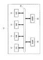
図1は、本実施形態に係る航空機管理装置10の電気的構成を示すブロック図である。本実施形態に係る航空機管理装置10は、編隊に参加している複数の航空機40(図2参照)の役割及び航空機40の軌道を求める装置である。なお、航空機管理装置10は、航空機40に備えられている。また、以下の説明において、編隊に参加している航空機40を我機ともいい、目標機42を彼機ともいう。
FIG. 1 is a block diagram showing an electrical configuration of an
本実施形態に係る航空機管理装置10は、各種演算処理を実行するCPU(Central Processing Unit)12、CPU12で実行される各種プログラム及び各種情報等が予め記憶されたROM(Read Only Memory)14、CPU12による各種プログラムの実行時のワークエリア等として用いられるRAM(Random Access Memory)16、各種プログラム及びシミュレーションの対象となる航空機40の機体諸元等の各種情報を記憶する記憶手段としてのHDD(Hard Disk Drive)18を備えている。
The
これらCPU12、ROM14、RAM16、HDD18、受信部20、及び送信部22は、システムバス24を介して相互に電気的に接続されている。
The
さらに、航空機管理装置10は、僚機情報や僚機の索敵や追尾により得られた目標機42(図2参照)の情報(目標機情報)等の各種情報を僚機から受信する受信部20、及びCPU12による演算結果や自機情報を僚機へ送信する送信部22を備えている。なお、僚機情報には、僚機の位置情報や僚機の速度等が含まれる。自機情報には、自機の位置情報や自機の速度等が含まれる。目標機情報には、目標機42の位置情報や目標機42の速度等が含まれる。
このように、本実施形態に係る航空機40は、各航空機40間で各種情報の送受信(データリンク)が可能とされている。すなわち、データリンクによって各航空機40は、自機情報、僚機情報、目標機情報、及び他の航空機40に対する指示情報等の各種情報を共有するためにネットワーク化されている。
Furthermore, the
As described above, in the
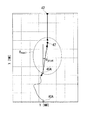
図2は、本実施形態に係る航空機40の役割及び軌道を示す模式図である。なお、図2では、一例として目標機42を一機のみ示しているが、目標機42は複数であってもよい。図2の例は、MRM(Medium Range Missiles)戦を模しており、航空機40から目標機42が視認できないほど離れた状態である。
FIG. 2 is a schematic view showing the role and trajectory of the
航空機40は、例えば、目標機42に対する誘導弾(ミサイル)44の発射(シュータ)、誘導弾44の誘導(ガイダ)、及び目標機42の索敵や追尾(センサ)が可能とされている。
The
すなわち、航空機40の役割は、例えば、目標機42の索敵や追尾、誘導弾44の誘導、及び誘導弾44の発射である。誘導弾44の誘導は、自機が発射した誘導弾44の誘導であってもよいし、僚機が発射した誘導弾44の誘導であってもよい。図2において例えば、航空機40A(シュータ機40A)の役割が誘導弾44の発射であり、航空機40B(ガイダ機40B)の役割が誘導弾44の誘導であり、航空機40C(センサ機40C)の役割は、目標機42の索敵や追尾である。
That is, the role of the
図2の例では、航空機40の索敵・追尾可能範囲、誘導弾44の誘導可能範囲、誘導弾44の射程範囲の順にその範囲は狭い。
In the example of FIG. 2, the range is narrow in the order of the searchable range of the
図2に示されるように、航空機40と目標機42とが向かい合って飛行している場合、シュータ機40Aは、目標機42と対向している状態(機首が向かい合う状態、所謂ヘッドオン)が、最も誘導弾44の射程範囲が長く、目標機42から離れて射撃することができるため好ましい。一方、ガイダ機40Bは、誘導可能範囲の端周辺に目標機42及び誘導弾44を捉えるように位置することが好ましい。センサ機40Cは、索敵・追尾可能範囲の端周辺に目標機42を捉えるように位置することが好ましい。目標機42の射程範囲を小さくすると共に、その射程範囲に自機が近づいたとしても、素早く目標機42の射程範囲から離脱できるためである。
As shown in FIG. 2, when the
次に、図2を参照して各航空機40の目標機42に対する一連の役割及び軌道について説明する。
Next, with reference to FIG. 2, a series of roles and trajectories for the
センサ機40Cは、目標機42の索敵や追尾を行い、目標機42の位置・速度情報をシュータ機40A,40Bへ送信する。シュータ機40Aは、誘導弾44の射程範囲に目標機42が進入すると、目標機42へ誘導弾44を発射する。目標機42がシュータ機40Aの誘導弾44の射程範囲に進入することは、すなわち、目標機42の射程範囲にシュータ機40Aが進入した可能性がある。このため、シュータ機40Aは、誘導弾44の発射直後に目標機42に対して反転、離脱する。このため、誘導弾44を発射したシュータ機40Aは、誘導弾44の誘導ができないので、シュータ機40Aが発射した誘導弾44の誘導を、ガイダ機40Bが行うこととなる。
なお、ガイダ機40Bは、誘導弾44を誘導可能範囲の端周辺で捉えて誘導弾44の誘導を行いながら目標機42からの回避を行う、所謂A−Poleをその軌道とする。同様にセンサ機40Cも、目標機42を索敵・追尾可能範囲の端周辺で索敵や追尾しながら目標機42からの回避を行うA−Poleをその軌道とする。
このように、目標機42に対する航空機40毎の役割に応じて、航空機40の軌道は決定される。
The
The
Thus, depending on the role of each
次に、本実施形態に係る航空機管理装置10による航空機40の軌道の算出(以下「最適軌道算出」という。)について説明する。
航空機管理装置10は、編隊に参加している複数の航空機40の軌道を算出するために、連続変数(状態変数及び制御変数)を離散化することで最適解を得る計算法、例えばDirect Collocation with Nonlinear Programming(DCNLP)が用いられる。
より詳しくは、DCNLPは、時間の関数である連続問題の連続変数を離散化することで、最適制御問題を非線形計画問題として扱い、目的関数(評価関数)の値が最小又は最大となる解を求めるものである。なお、DCNLPは、状態変数に対する不等式制約条件を扱いやすく、初期条件や制約条件に対するロバスト性が高い。また、運動方程式を制約条件として扱うこともできる。
Next, calculation of the trajectory of the aircraft 40 (hereinafter, referred to as “optimal trajectory calculation”) by the
The
More specifically, DCNLP treats an optimal control problem as a non-linear programming problem by discretizing continuous variables of a continuous problem which is a function of time, and a solution in which the value of the objective function (evaluation function) is minimum or maximum It is what you want. In addition, DCNLP is easy to handle inequality constraints on state variables, and has high robustness to initial conditions and constraints. Also, the equation of motion can be treated as a constraint.
図3は、DCNLPの概念を示す模式図である。なお、図3の縦軸及び横軸は共に状態変数とされる。
DCNLPでは、問題を時間tによってN個のノード(以下「離散点」ともいう。)t1〜tNに離散化する。本実施形態に係るDCNLPでは、航空機40の挙動を示す運動方程式に対して制御変数を代入することで状態変数をノードとして算出する。なお、これに限らず、他の適切な方法によって状態変数がノードとして設定されてもよい。
まず、ノードt1〜tNの初期推定解を算出するために、制御変数の初期値が運動方程式に代入される。なお、ノードt1〜tNの初期推定解については、制御変数を運動方程式に代入する方法の他に、他の適切な方法によって設定されてもよい。このノードは、各ノードにおける制御変数や状態変数の微小変化に対する目的関数の変化分に基づき、修正される(図3の計算途中)。そして、後述する制約条件を満たし、かつ目的関数(評価関数ともいう。)の値が最小(又は最大)となるノードが航空機40の軌道としての最適解とされる。なお、算出されたノードの間は、例えば多項式等により補間される。
FIG. 3 is a schematic view showing the concept of DCNLP. The vertical axis and the horizontal axis in FIG. 3 are both state variables.
In DCNLP, the problem is discretized into N nodes (hereinafter also referred to as “discrete points”) t 1 to t N by time t. In DCNLP which concerns on this embodiment, a state variable is calculated as a node by substituting a control variable with respect to the motion equation which shows the behavior of the
First, in order to calculate an initial estimated solution of nodes t 1 to t N , initial values of control variables are substituted into the equation of motion. In addition to the method of substituting the control variable into the equation of motion, the initial estimated solutions of the nodes t 1 to t N may be set by other appropriate methods. This node is corrected based on the change of the objective function with respect to the minute change of the control variable or the state variable in each node (during the calculation of FIG. 3). Then, a node that satisfies the constraints described later and has a minimum (or maximum) value of the objective function (also referred to as an evaluation function) is determined as the optimal solution as the trajectory of the
このように、航空機40の軌道を時間的に連続したものとして算出するよりも、DCNLPを用いて状態変数や制御変数を離散化して扱うことにより計算量が少なくなり、短時間での軌道算出が可能となる。
As described above, rather than calculating the trajectory of the
しかしながら、このノードは、連続していないために状態変数によっては、実際の航空機40では実現できない軌道ともなり得る。そこで、算出した次のノードと実際にあるべき次のノードとのずれ量が0(零)とする制約条件が与えられる。この制約条件は、DCNLPでいうところのdefectであり、この制約条件を満たすことにより、算出されたノードは航空機40の運動方程式を満たしたものとなり得る。
However, this node may be an orbit that can not be realized by the
図4は、DCNLPのdefectの概念を示す模式図である。図4において、横軸が時間であり、縦軸が航空機40の位置を示す状態変数であり、ノードA(tk,Xk)とノードC(tk+1,Xk+1)が隣接する二つの離散点である。そして、本来、ノードA,Cは、航空機40の軌道上の位置であるため、微分方程式fの関係で繋がるはずである。
そこで、ノードA,Cの微分値である傾きを各々fk,fk+1とし、隣接する二つのノードA,C間の差と二つのノードA,Cにおける傾きfk,fk+1に基づく変化量との差を0とすることを、defectで定義される制約条件とする。
FIG. 4 is a schematic view showing the concept of defects of DCNLP. 4, a horizontal axis represents time, and the vertical axis represents the state variable indicating a position of the
Therefore, the node A, each f k the slope is a differential value of C, and f k + 1, two adjacent nodes A, the difference between C and two nodes A, inclination f k in C, based on the f k + 1 variation Let the difference between and be 0 be the constraint defined by defect.
そして、下記(1)式で表される二つのノードA,Cの平均微分値を用いて、二つのノードA,Cにおける傾きfk,fk+1に基づく変化量を下記(2)式のように表す。下記(2)式で算出される値は、図4における点Bとなる。なお、(2)式に基づく点Bの算出方法は、一例であり、これに限られるものではない。 Then, using the average differential value of the two nodes A and C represented by the following equation (1), the amount of change based on the slopes f k and f k + 1 at the two nodes A and C is given by the following equation (2) Indicate The value calculated by the following equation (2) is a point B in FIG. In addition, the calculation method of the point B based on (2) Formula is an example, It is not restricted to this.

このように、点Bは、前のノードAから帰納的に求まる値であり、状態変数が運動方程式を満たしているならば点BとノードCとは一致するものであり、点BとノードCとのズレがdefectとなる。具体的には、二つのノードA,C間の差(Xk+1−Xk)と(2)式で表される変化量vとの差がdefectとなる。
すなわち、defectは、隣接するノードA,Cの微分値に基づいて求まる点BとノードCとの残差であり、defectをζkとした下記(3)式で表される。
Thus, the point B is a value that can be found inductively from the previous node A, and if the state variable satisfies the equation of motion, the point B and the node C coincide, and the point B and the node C The gap between the two becomes defect. Specifically, the difference between the difference (X k + 1 −X k ) between the two nodes A and C and the change amount v represented by the equation (2) is defect.
That is, defect is a residual between point B and node C obtained based on differential values of adjacent nodes A and C, and is expressed by the following equation (3) with defect as ζ k .
そして、ζk=0となれば、点BとノードCとが一致し、DCNLPを用いて算出されたノードA,Cは運動方程式を満たすこととなる。このように、defectで定義される制約条件を満たす解(状態変数)は運動方程式を満たしながら滑らかに連続することとなる。 Then, if ζ k = 0, the point B and the node C coincide with each other, and the nodes A and C calculated using DCNLP satisfy the equation of motion. Thus, a solution (state variable) that satisfies the constraint defined by defect will be smoothly continuous while satisfying the equation of motion.
そして、航空機管理装置10は、defectで定義される制約条件、及び航空機40の役割に応じた制約条件を満たす軌道のうち、役割に応じた目的関数によって得られる目的関数値(評価値)に基づいて最適な軌道を決定する。
Then, the
以下に、航空機40の役割に応じた制約条件について詳細に説明する。
なお、航空機40の役割とは、例えば、上述したように誘導弾44の発射を行うシュータ(シュータ機40A)、目標の索敵や追尾を行うセンサ(センサ機40C)、及び誘導弾44の誘導を行うガイダ(ガイダ機40B)である。
The constraints according to the role of the
The role of the
まず、本実施形態に係る状態変数Xは、航空機40の姿勢を示す方位角をψ、航空機40の位置を示す我機座標をx,yとして、下記(4)式で表される。なお、一例として、我機座標xは北方向を基準とし、我機座標yは東方向を基準とする。また、本実施形態では、航空機40の速度及び高度は一定としているが、速度及び高度も状態変数としてもよい。
First, the state variable X according to the present embodiment is represented by the following equation (4), where the azimuth angle indicating the attitude of the
運動方程式における制御変数uは、迎角をα、バンク角をφ、推力をTとして、下記(5)式で表される。 The control variable u in the equation of motion is expressed by the following equation (5), where the attack angle is α, the bank angle is φ, and the thrust is T.
そして、航空機40の運動方程式は、一例として、質量をm、速度をv、飛行経路角をγ、揚力をL、抗力をDとして、下記(6)式の3自由度運動方程式で表される。(6)式で表される運動方程式に上述した制御変数を離散変数として代入することで、航空機40の状態変数が算出され、これにより航空機40の軌道の初期推定解が算出されることとなる。なお、これに限らず、他の適切な方法によって状態変数を設定することにより、航空機40の軌道の初期推定解が設定されてもよい。
The equation of motion of the
次に航空機40の役割に応じた制約条件について具体的に説明する。
まず、航空機40の役割にかかわらず共通の制約条件(以下「共通制約条件」という。)について説明する。
共通制約条件は、下記(7)式から(10)式で表される。
Next, constraints according to the role of the
First, regardless of the role of the
The common constraint is expressed by the following equations (7) to (10).
(7)式は、defect:ζk=0とする制約条件である。(8)式は、速度を一定とする制約条件であり、Dは抗力である。(9)式は、高度を一定とする制約条件である。なお、(7)式から(9)式のように等式で表される制約条件を等式制約条件という。 Expression (7) is a constraint condition that defect: ζ k = 0. Equation (8) is a constraint that makes velocity constant, and D is drag. Equation (9) is a constraint that makes the height constant. The constraint expressed by an equation as in the equations (7) to (9) is called an equation constraint.
なお、速度の変化を許容する場合は、(8)式の右辺を0とせずに、例えばある一定の範囲としてもよい。また、高度の変化も許容する場合には、(9)式の右辺を0とせずに、例えばある一定の範囲としてもよい。さらに、(8),(9)式とは異なる他の制約条件を追加してもよい。 When the change in speed is allowed, the right side of the equation (8) may not be 0 but may be, for example, a certain range. In addition, when a change in altitude is also allowed, the right side of the equation (9) may not be 0, for example, a certain range. Furthermore, other constraints different from the equations (8) and (9) may be added.
(10)式のNzは航空機40の旋回時に加えられる垂直荷重倍数(以下「旋回G」という。)であり、(10)式では一例として、4G以上の旋回Gが加えられないように制約される。この旋回Gの上限は、航空機40の性能や航空機40の戦闘状況に応じて決定されるものであり、MRM戦よりも近接戦闘においてはより大きな値とされてもよい。
また、(10)式のように不等式で表される制約条件を不等式制約条件という。
In the equation (10), Nz is a vertical load multiple (hereinafter referred to as "swing G") applied when the
Also, the constraint expressed by the inequality as in equation (10) is called the inequality constraint.
次にセンサ機40Cに特有の制約条件及び目的関数について、図5を参照して説明する。図5において、縦軸方向が南北(図面上方向が北)であり、横軸方向が東西(図面右方向が東)である。なお、ガイダ機40Bの制約条件及び目的関数は、索敵・追尾可能範囲と誘導可能範囲(誘導弾44を捉えることができる誘導電波の覆域)とが同一である場合、センサ機40Cと同様である。
Next, constraints and an objective function specific to the
また、以下の説明において、目標機42の軌道は、一例として直進と仮定するが、これに限らず、目標機42の軌道を他のシミュレーション等を用いて直進以外としてもよい。
In the following description, the trajectory of the
センサ機40Cは、彼機である目標機42を常にレーダの覆域内に捉えることが必要あり、これがセンサ機40Cの役割に応じた制約条件となる。この制約条件は、アジマス方向のレーダ覆域をRCAZとし、我機から見た彼機の方位をψBtoRとして、下記(11)式で表される。
It is necessary for the
(11)式は、センサ機40の軌道を算出するための不等式制約条件となる。なお、センサ機40Cの等式制約条件は、一例として不要としているが、何かしらの等式制約条件を設定してもよい。
Equation (11) is an inequality constraint for calculating the trajectory of the
センサ機40Cの役割に応じた目的関数J(ξ)は、彼機座標を(xred,yred)とし、重み係数をk1,k2として、下記(12)式で表される。なお、目的関数J(ξ)には、状態変数X及び制御変数uが入力され、これによって求められる目的関数値が評価値とされる。
An objective function J (ξ) according to the role of the
目的関数J(ξ)である(12)式の右辺の第1項は、各ノード(離散点)における航空機40(我機)と目標機42(彼機)との距離(以下「彼我間距離」という。)の総和であり、第2項は、各ノードにおける航空機40(我機)のバンク角の二乗和である。
航空機40は、可能な限り目標機42から離れることが好ましいため、第1項の値はより大きい方が好ましい。第2項は、バンク角の安定性を示した項であり、第2項の値が小さい程、バンク角の変動が少ない安定した軌道となるため、第2項の値は小さい方が好ましい。さらに、彼我間距離及びバンク角の目的関数J(ξ)に対する重みを調整するために、第1項及び第2項には重み係数k1,k2が乗算される。
また、目的関数値が小さい程評価を高くするために、第1項は負の関数とされ、第1項に第2項が加算される。
The first term of the right side of the equation (12) which is the objective function J (ξ) is the distance between the aircraft 40 (in-house) and the target plane 42 (in-hand) at each node (discrete point) The second term is the sum of squares of the bank angles of the aircraft 40 (I) at each node.
As it is preferable that the
Also, in order to increase the evaluation as the objective function value decreases, the first term is a negative function, and the second term is added to the first term.
次にシュータ機40Aに特有の制約条件及び目的関数について、図6を参照して説明する。なお、図6において、縦軸方向が南北(図面上方向が北)であり、横軸方向が東西(図面右方向が東)である。
Next, constraints and an objective function specific to the
シュータ機40Aは、誘導弾発射時に機首が目標機42に向いている必要がある。これがシュータ機40Aの役割に応じた制約条件となる。この制約条件は、誘導弾44の発射時刻をtshootとし、そのときの我機の方位をψ(tshoot)として、下記(13)式で表される。
The
なお、(13)式は等式制約条件とはされずに、左辺が所定角度の範囲内(例えば±5°)とされる不等式制約条件とされてもよい。 Equation (13) may be an inequality constraint in which the left side is within a range of a predetermined angle (for example, ± 5 °) without being an equality constraint.
また、シュータ機40Aは、誘導弾発射時に彼我間距離が誘導弾44の射程範囲Rmaxl内であり、かつ、シミュレーション時間内に誘導弾44を発射することが不等式制約条件となる。この不等式制約条件は、シミュレーション時間をt1からtNとし、誘導弾発射時間をtshootとして、下記(14)式で表される。なお、一例として、射程範囲Rmaxlは、シュータ機40Aと目標機42との相対角(アングル・オフ)によって異なるものである。
Further, the
また、シュータ機40Aの役割に応じた目的関数J(ξ)は、重み係数をk3〜k7として、下記(15)式で表される。
Further, an objective function J (ξ) according to the role of the
(15)式の右辺の第1項はシミュレーションの開始から誘導弾発射までの時間であり、第2項は誘導弾発射時の彼我間距離であり、第3項は被我間距離の最小値(以下「最小彼我間距離」という。)であり、第4項は誘導弾発射後の彼我間距離の総和であり、第5項は各ノードにおける我機のバンク角の二乗和である。なお、第1項から第5項には各々重み係数k3〜k7が乗算される。
すなわち、シュータ機40Aは、誘導弾発射時までの時間を小さく、かつ、誘導弾発射時の彼我間距離を大きく、かつ最小彼我間距離を大きく、かつ誘導弾発射後の彼我間距離の和を大きくする軌道であることが好ましい。そして、(15)式で表される目的関数J(ξ)によって算出される値が小さい方がより評価が高い。
The first term on the right side of equation (15) is the time from the start of the simulation to the launch of the induced bullet, the second term is the distance between the two at the time of launch of the induced bullet, and the third term is the minimum distance between subjects The fourth term is the sum of the inter-person distance after the induction bullet is fired, and the fifth term is the sum of squares of the bank angles of our aircraft at each node. is there. Incidentally, each of the weighting factor k 3 to k 7 is multiplied from the first term in
That is, the
(12)式及び(15)式に示されるように目的関数J(ξ)は、航空機40の役割にかかわりなく、航空機40と目標機42との間の距離である彼我間距離を算出するための関数が含まれ、彼我間距離が役割に応じて適した値となる軌道が最適な軌道とされる。
As shown in the equations (12) and (15), the objective function J (ξ) calculates the distance between him, which is the distance between the
次に、上述したDCNLPを用いた最適軌道算出(「制約条件付き非線形計画問題」ともいう。)について説明する。
図7は、最適軌道算出の処理の流れを示すフローチャートである。最適軌道算出は、航空機管理装置10によって実行される。
Next, optimal trajectory calculation (also referred to as “constraint nonlinear programming problem”) using the above-described DCNLP will be described.
FIG. 7 is a flowchart showing the flow of the process of calculating the optimum trajectory. The optimal trajectory calculation is performed by the
まず、ステップ100では、初期推定解となる制御変数uを運動方程式に代入することで航空機40の機動を算出するが、初期推定解は他の適切な方法で設定されてもよい。ここで、初期推定解によって求解の実現可能性や求解までの計算時間が変化するので、制約条件をより確実に満たす初期推定解とする必要がある。なお、初期推定解となる制御変数uは、一例として、航空機40のパイロット自身が経験値に基づいて設定する。
First, at
ステップ102では、設定された役割に応じた制約条件を満たす制御変数u及び状態変数Xが役割に応じた目的関数J(ξ)に代入され、目的関数値J(評価値)が算出される。 In step 102, the control variable u and the state variable X that satisfy the constraints according to the set role are substituted into the objective function J (ξ) according to the role, and the objective function value J (evaluation value) is calculated.
次のステップ103では、制御変数・状態変数(制御変数及び状態変数少なくとも一方)の微小変化量を算出する。なお、ステップ103では、一例として、微小変化量を制御変数・状態変数に応じた予め定められた値とする。 In the next step 103, a minute change amount of the control variable / state variable (at least one of the control variable and the state variable) is calculated. In step 103, as an example, the minute change amount is set to a predetermined value according to the control variable / state variable.
次のステップ104では、制御変数・状態変数(制御変数及び状態変数少なくとも一方)を修正する。なお、制御変数・状態変数の修正量は、制御変数・状態変数の前回の微小変化に対する目的関数値Jの変化分に応じて算出される。 In the next step 104, control variables and state variables (at least one of control variables and state variables) are corrected. The correction amount of the control variable / state variable is calculated according to the change of the objective function value J with respect to the previous slight change of the control variable / state variable.
次のステップ106では、修正した制御変数・状態変数を用いて目的関数値Jを算出する。 In the next step 106, an objective function value J is calculated using the corrected control variables and state variables.
次のステップ108では、制御変数・状態変数の微小変化に対する目的関数値Jの変化量を算出する。 In the next step 108, the amount of change of the objective function value J with respect to the minute change of the control variable / state variable is calculated.
次のステップ110では、評価の終了条件を満たしたか否かを判定し、肯定判定の場合は本シミュレーションを終了する。一方、否定判定の場合はステップ104へ戻り、制御変数や状態変数を微小変化させ、目的関数値の変化量の算出を繰り返す。 In the next step 110, it is determined whether or not the evaluation end condition is satisfied, and in the case of a positive determination, the present simulation is ended. On the other hand, in the case of a negative determination, the process returns to step 104, the control variable and the state variable are minutely changed, and the calculation of the change amount of the objective function value is repeated.
ここで、ステップ110における評価の終了条件について、図8を参照して説明する。図8は、横軸が制御変数・状態変数ξを示し、縦軸が目的関数値Jを示し、点a〜eは制御変数・状態変数ξに対する目的関数値Jの変化を示している。 Here, the termination condition of the evaluation in step 110 will be described with reference to FIG. In FIG. 8, the horizontal axis indicates the control variable / state variable 、, the vertical axis indicates the objective function value J, and points a to e indicate changes in the objective function value J with respect to the control variable / state variable ξ.
終了条件としては、例えば下記のように4つの条件がある。
条件1:制御変数・状態変数ξの変化量が許容値Tolξよりも小さくなった場合。
条件2:目的関数値Jの変化量が許容値TolFunよりも小さくなった場合。
条件3:1次の最適性の尺度が許容値未満となった場合。
条件4:ステップ104からステップ108までの反復回数、又は目的関数値Jの評価回数が許容値よりも大きくなった場合。
As the termination condition, there are, for example, the following four conditions.
Condition 1: The amount of change in the control variable / state variable 小 さ く becomes smaller than the allowable value Tol ξ.
Condition 2: The amount of change in the objective function value J becomes smaller than the allowable value TolFun.
Condition 3: The measure of the optimality of the first order is less than the tolerance value.
Condition 4: The number of iterations from step 104 to step 108 or the number of evaluations of the objective function value J is larger than the allowable value.
次に上記条件3における1次の最適性について説明する。 Next, the first-order optimality under the above condition 3 will be described.
制約条件付き非線形計画問題に対する1次の最適性は、Karush-Kuhu-Tucker条件(以下「KKT条件」)に基づいて求められる。
KKT条件は、制約条件が無い場合に目的関数J(ξ)の最小値近傍(図8における点e近傍であり、目的関数値Jの変化が下に凸の状態)において、傾きである勾配∇J(ξ)が略零になるという条件に相当する。しかし、制約条件を考慮する場合には下記(16)式で表される定義となる。
なお、1次の最適性を満たすことは、必要条件ではあるが十分条件ではない。目的関数値Jの変化が上に凸となる最大値近傍においても勾配∇J(ξ)=0となり得るためである。
The first order optimality for the constrained nonlinear programming problem is determined based on the Karush-Kuhu-Tucker condition (hereinafter "KKT condition").
The KKT condition is a gradient ∇ which is a slope in the vicinity of the minimum value of the objective function J (ξ) (near the point e in FIG. 8 and in which the change of the objective function value J is convex downward) when there is no constraint. This corresponds to the condition that J (ξ) becomes substantially zero. However, in the case of considering the constraint condition, the definition is represented by the following equation (16).
It is a necessary condition but not a sufficient condition to satisfy the first-order optimum. This is because the gradient ∇J (ξ) = 0 can be obtained near the maximum value where the change of the objective function value J is convex upward.
そして、KKT条件に使用するラグランジュ関数L(ξ,λ)を下記(16)式のように表す。なお、下記(16)式において、g(ξ)は不等式制約条件式であり、h(ξ)は等式制約条件である。そして、λgは不等式制約条件式に関するラグランジュ乗数であり、λhは等式制約条件式に関するラグランジュ乗数である。
そして、満たすべきKKT条件は、ラグランジュ関数を用いて下記(17),(18)式のように表される。 Then, the KKT conditions to be satisfied are expressed as the following equations (17) and (18) using the Lagrange function.
さらに、最適解の十分性を示す2次の十分条件は、ラグランジュ関数L(ξ,λ)のHessian行列が、下記(19)式で表されるように正定となる条件である。
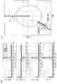
次に、図9から図12を参照して、最適軌道算出結果の例について説明する。図9から図12の(A)は最適軌道算出によって得られた我機の最適軌道解を示し、図9から図12の(B)は、制御変数である迎角、バンク角、及び推力の離散化された時間変化と共に、参考情報としての旋回Gの時間変化のグラフである。
また、各図(A)のX=0[NM]から最適軌道算出が開始される我機のうち、白色が初期推定解であり、斜線でハッチングされたものが最適軌道算出によって算出された最適軌道解である。なお、目標機42は北方向から直進すると仮定している。
Next, an example of the optimum trajectory calculation result will be described with reference to FIGS. 9 to 12. (A) of FIG. 9 to FIG. 12 shows the optimal orbit solution of our machine obtained by the optimal orbit calculation, and (B) of FIG. 9 to FIG. 12 shows the attack angle, bank angle and thrust which are control variables. It is a graph of the time change of turning G as reference information with the time change discretized.
In addition, among our machines whose optimal trajectory calculation is started from X = 0 [NM] in each figure (A), the white is the initial estimated solution, and the one hatched with diagonal lines is the optimal calculated by optimal trajectory calculation. It is an orbital solution. In addition, it is assumed that the
図9,10はセンサ機40Cの最適軌道算出結果であり、図9はセンサ覆域が±60°であり、図10はセンサ覆域が±120°である。
9 and 10 show the calculation results of the optimum trajectory of the
図11,12はシュータ機40Aの最適軌道算出結果であり、図11は誘導弾44の射程範囲が約50マイル、図12は誘導弾44の射程範囲が約80マイルである。なお、図11,12における一点鎖線で囲まれた範囲は誘導弾44の大まかな射程範囲を示している。
11 and 12 show the calculation results of the optimum trajectory of the
次に、航空機40の軌道と役割の同時最適化(以下「同時最適化処理」という。)について説明する。 Next, simultaneous optimization of the trajectory and role of the aircraft 40 (hereinafter referred to as “simultaneous optimization process”) will be described.
本実施形態に係る同時最適化処理は、上述した最適軌道算出と共に行われる。
同時最適化処理では、上述した役割に応じた目的関数及び制約条件をすべて統合して扱う。さらに、役割に応じた目的関数及び制約条件の各々に対して、変数(以下「インディケータ変数」という。)が付与される。このインディケータ変数は、航空機40に設定した役割に対応しない目的関数及び制約条件を無効化するためのものである。
The simultaneous optimization process according to the present embodiment is performed together with the above-described optimal trajectory calculation.
In the simultaneous optimization process, all objective functions and constraints according to the roles described above are integrated and handled. Furthermore, a variable (hereinafter referred to as "indicator variable") is assigned to each of the objective function and the constraint condition according to the role. This indicator variable is for invalidating the objective function and the constraint that do not correspond to the role set in the
そして、同時最適化処理は、航空機40に設定した役割に対応しない目的関数及び制約条件が無効となるように、インディケータ変数の値を目的関数毎及び制約条件毎に決定する。無効化された目的関数及び制約条件は、航空機40の軌道の算出に影響を与えないこととなるので、無効とされない目的関数及び制約条件のみに基づいて軌道が算出されることとなる。
そして、同時最適化処理は、航空機40の役割、すなわち無効とする目的関数及び制約条件を変化させる毎に、航空機40の軌道を算出してその結果を評価することによって、航空機40の最適な役割及び軌道を同時に決定することができる。
Then, the simultaneous optimization process determines the value of the indicator variable for each objective function and for each constraint so that the objective function and the constraint that do not correspond to the role set in the
Then, the simultaneous optimization process calculates the trajectory of the
なお、本実施形態に係るインディケータ係数は、一例として、1又は0に変化される。
これにより、航空機40に設定した役割に対応する目的関数及び制約条件に付与されたインディケータ変数は1とされて有効とされる。一方、航空機40に設定した役割に対応しない目的関数及び制約条件に付与されたインディケータ変数は0とされ、無効化される。
換言すると、インディケータ係数によって航空機40の役割が設定される。すなわち、インディケータ係数が1とされた目的関数及び制約条件に対応する役割が、航空機40の役割として設定されることとなる。
The indicator coefficient according to the present embodiment is changed to 1 or 0 as an example.
As a result, the objective function corresponding to the role set for the
In other words, the role of the
次に航空機40の役割の決定について具体的に説明する。なお、以下の説明では、一例として、航空機40である我機が2機であり、目標機42である彼機が2機であると仮定して説明する。このため、2機の我機はB#1、B#2で表記され、2機の彼機はR#1、R#2で表記される。
Next, the determination of the role of the
航空機40の役割をシュータ機40A(SHT)とする場合における、目的関数及び制約条件を表1に示す。
The objective function and the constraint in the case where the role of the
表1におけるαはB#1又はB#2であり、βはR#1又はR#2である。
一例として、目的関数JSHT B#1,R#2は、B#1がR#2へ誘導弾44を発射する場合の目的関数値である。また、不等式制約条件gSHT B#1,R#2は、B#1がR#2へ誘導弾44を発射する場合の不等式制約条件である。また、等式制約条件hSHT B#1,R#2は、B#1がR#2へ誘導弾44を発射する場合の等式制約条件である。
In Table 1, α is
As an example, the objective functions J SHT B # 1 and R # 2 are objective function values when
次に、航空機40の役割をセンサ機40C(SNS)とする場合における、目的関数及び制約条件を表2に示す。
Next, Table 2 shows the objective function and the constraint in the case where the role of the
表2におけるαはB#1又はB#2であり、βはR#1又はR#2である。
一例として、目的関数JSNS B#1,R#1は、B#1がR#2を索敵・追尾する場合の目的関数である。また、不等式制約条件gSHT B#1,R#1は、B#1がR#2を索敵・追尾する場合の不等式制約条件である。なお、等式制約条件は、上述したDCNLPで説明したように一例として不要とする。
In Table 2, α is
As an example, the objective functions J SNS B # 1 and R # 1 are objective functions when
また、設定された役割にかかわらず、2機の我機に共通の制約条件が表3に示すように設定されてもよい。 Also, regardless of the role set, the constraint conditions common to the two aircraft may be set as shown in Table 3.
表3における不等式制約条件のαはB#1又はB#2、若しくはB#1とB#2である。そして、特に、αをB#1とB#2とした不等式制約条件は、僚機同士の衝突回避を目的とし、B#1とB#2との距離が所定値よりも長くなることを条件としたものである。
The inequality constraint α in Table 3 is
次に、インディケータ変数について説明する。
表4はインディケータ変数の種類を示したものである。表4においてインディケータ変数はδijで表記される。タスクiは我機が行う役割を示し、エージェントjはタスク(役割)を行う我機を示す。
Next, indicator variables will be described.
Table 4 shows the types of indicator variables. In Table 4, the indicator variable is represented by δ ij . The task i indicates the role played by the machine, and the agent j indicates the machine performing the task (role).
そして、タスクiをエージェントjに割り当てる場合はδij=1とされ、タスクiをエージェントjに割り当てない場合はδij=0とされる。例えば、エージェントであるB#1がR#1に誘導弾44を発射するというタスクを行う場合は、δ11は1とされる一方、他のタスクiとエージェントjの組み合わせのδijは0とされる。
Then, when task i is assigned to agent j, δ ij = 1 is set, and when task i is not assigned to agent j, δ ij = 0. For example, when the
なお、本実施形態では、一例として、同一の目標機42に対して、同一の役割の航空機40が複数割り当てられることはない。すなわち、例えばδ11=1の場合にはδ12=0となる。このことは、タスク(役割)の割り当てに関する等式制約条件htsk=0となり、より具体的には下記(20)式で表される。
In the present embodiment, as an example, a plurality of
すなわち、タスクの割り当てに関する制約条件は、1機の我機は1つの役割しか割り当てられないというものである。 In other words, the constraint on task assignment is that one machine can only be assigned one role.
次に、統合した目的関数と統合した制約条件に付いて説明する。
下記(21)式は、統合した目的関数(以下「統合目的関数JINT」という。)である。
Next, the integrated objective function and the integrated constraint will be described.
The following equation (21) is an integrated objective function (hereinafter referred to as “integrated objective function J INT ”).
統合目的関数JINTは、目的関数毎にインディケータ変数δijが乗算され、インディケータ変数δijが乗算された目的関数の総和とされる。そして、統合目的関数JINTから目的関数値(評価値)を算出する場合に、全ての目的関数のインディケータ変数δijが1又は0とされる。 Integrated objective function J INT is multiplied indicator variable [delta] ij for each objective function, indicator variable [delta] ij is the sum of the objective function multiplied. Then, when calculating the objective function values (evaluation values) from the integrated objective function J INT, the indicator variable [delta] ij for all objective functions are 1 or 0.
下記(22)式は、統合した等式制約条件(以下「統合等式制約条件hINT」という。)である。統合等式制約条件hINTは、各等式制約条件を一括して扱う。 The following equation (22) is an integrated equation constraint (hereinafter referred to as “integrated equation constraint h INT ”). Integral equality constraints h INT collectively treat each equality constraint.
なお、上述したようにセンサ機40Cには等式制約条件が設定されないので、(22)式はセンサ機40Cに特有の等式制約条件が含まれていない。しかしながら、センサ機40Cにも等式制約条件が設定されている場合は、下記(23)式で表されるセンサ機40Cに特有の等式制約条件が(22)式に追加される。
As described above, since the equation constraint condition is not set in the
統合等式制約条件hINTは、等式制約条件毎にインディケータ変数δijが乗算される。そして、統合等式制約条件hINTの可否を判定する場合に、全ての等式制約条件のインディケータ変数δijが1又は0とされる。 The integral equation constraint h INT is multiplied by the indicator variable δ ij for each equation constraint. Then, when determining whether or not the integrated equation constraint h INT is to be determined, the indicator variables δ ij of all the equation constraints are set to 1 or 0.
上記(21)式から(23)式で表されるように、インディケータ変数δijは、目的関数及び等式制約条件に対して各々乗算される。そして、航空機40に設定した役割に対応する目的関数及び等式制約条件に付与されているインディケータ係数δijは1とされる。一方、航空機40に設定した役割に対応しない、不要な目的関数及び等式制約条件に付与されているインディケータ係数δijは0とされ、不要な目的関数及び等式制約条件は無効化される。
このように、インディケータ係数δijによって不要な目的関数の値は0となるので、統合目的関数JINTは不要な目的関数の影響を受けることなく、航空機40に設定した役割に応じた目標関数値(評価値)を算出できる。また、不要な等式制約条件の値が0となることで等式制約条件が成立するので、統合等式制約条件hINTは不要な等式制約条件の影響を受けることなく、航空機40に設定した役割に応じた等式制約条件のみを判定できる。
The indicator variables δ ij are respectively multiplied with respect to the objective function and the equality constraints as expressed by the above equations (21) to (23). The indicator coefficient δ ij assigned to the objective function and the equation constraint corresponding to the role set for the
Thus, since the value of the unnecessary objective function becomes 0 by the indicator coefficient δ ij , the integrated objective function J INT is not influenced by the unnecessary objective function, and the objective function value according to the role set in the aircraft 40 (Evaluation value) can be calculated. Further, since the equation constraint is satisfied when the value of the unnecessary equation constraint is 0, the integrated equation constraint h INT is set to the
さらに、下記(24)式は、統合した不等式制約条件(以下「統合不等式制約条件gINT」という。)である。
統合不等式制約条件gINTは、不等式制約条件に対して0とされると不等式が成立するようにインディケータ変数δijが付与される。具体的には、(24)式に表されるように、不等式制約条件毎に“(1−δij)・M”の項が付与され、gの値はこの項で減算される。なお、Mは、想定されるgの値よりも十分に大きな正の整数である。そして、統合不等式制約条件gINTの可否を判定する場合に、全ての不等式制約条件のインディケータ変数δijが1又は0とされる。
すなわち、航空機40の役割に対応した不等式制約条件のインディケータ変数δijは1とされるので、上記項の値は0となり、上記項の影響はない。一方、航空機40の役割に対応しない、不要な不等式制約条件ではインディケータ変数δijが0とされ、上記項は大きな整数となっていかなる状態においても不等式が成立し、統合不等式制約条件gINTに影響を与えないこととなる。従って、統合不等式制約条件gINTは不要な不等式制約条件の影響を受けることなく、航空機40に設定した役割に応じた不等式制約条件のみを判定できる。
Integral inequality constraint condition g INT is given indicator variable δ ij such that an inequality is satisfied when it is set to 0 with respect to the inequality condition constraint. Specifically, as represented by equation (24), the term "(1-δ ij ) · M" is given for each inequality constraint, and the value of g is subtracted in this term. Here, M is a positive integer sufficiently larger than the assumed value of g. Then, when determining whether or not the integrated inequality constraint g INT is to be determined, the indicator variables δ ij of all the inequality constraints are set to 1 or 0.
That is, since the indicator variable δ ij of the inequality constraint corresponding to the role of the
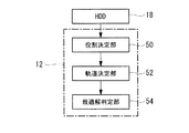
図13は、本実施形態に係る航空機管理装置10における航空機40の役割及び軌道の同時最適化(以下「役割軌道最適化処理」という。)に関する機能ブロック図である。
FIG. 13 is a functional block diagram regarding the simultaneous optimization of the role and trajectory of the aircraft 40 (hereinafter referred to as “role trajectory optimization processing”) in the
CPU12は予めHDD18に記憶されているプログラムを実行することにより、役割決定部50、軌道決定部52、及び最適解判定部54の機能を有する。また、HDD18には、上述した統合目的関数JINT、統合等式制約条件hINT、及び統合不等式制約条件gINTが記憶されている。
The
役割決定部50は、航空機40の役割を決定する。
具体的には、役割決定部50は、統合目的関数JINT、統合等式制約条件hINT、及び統合不等式制約条件gINTをHDD18から読み出し、航空機40に設定した役割に応じて、統合目的関数JINT、統合等式制約条件hINT、及び統合不等式制約条件gINTのインディケータ変数δijを1又は0とする。
The
Specifically, the
軌道決定部52は、役割決定部50によってインディケータ変数δijが1又は0とされた後の統合目的関数JINT、統合等式制約条件hINT、及び統合不等式制約条件gINTに基づいて、図7に示される最適軌道算出を行うことによって航空機40の役割に応じた最適な軌道を算出する。
The
なお、役割決定部50は、インディケータ変数δijを変化させることで、航空機40に設定する役割を変化させる。そして、軌道決定部52は、航空機40に設定する役割が変化される毎に、航空機40の役割に応じた最適な軌道を算出する。
In addition, the
最適解判定部54は、航空機40に設定した役割毎に算出された複数の軌道のうち、統合目的関数を最も小さくする役割とそのときの軌道を、最適な役割及び最適な軌道とし、実際に航空機40に設定する役割及び軌道として決定する。
これにより、航空機40の役割及び軌道が同時に最適化される。
Among the plurality of trajectories calculated for each of the roles set for the
Thereby, the role and trajectory of the
なお、役割軌道最適化処理では、航空機40の役割を変化させるために、例えば遺伝的アルゴリズム等の進化的計算手法や分岐限定法を用い、このループの中でDCNLPを解くことで最適な軌道が算出される。
In the role trajectory optimization process, in order to change the role of the
なお、航空機管理装置10は、一例として、編隊を構成する全ての航空機40が有しているが、例えば、所定の僚機(例えばリーダ機)が役割軌道最適化処理を実行して僚機の役割及び軌道を決定し、決定した役割及び軌道は役割軌道情報として僚機に送信する。僚機に送信された役割軌道情報は、僚機のMFDに表示され、僚機のパイロットは表示された情報に従って操縦する。
The
以上説明したように、本実施形態に係る航空機管理装置10は、離散化した航空機40の制御変数を航空機40の運動方程式に代入することで軌道を示すN個のノードを算出し、又は他の適切な方法で軌道を示すNこのノードを設定し、各ノード間において、次のノードと実際にあるべき次のノードとのずれ量を0とする制約条件及び航空機40の役割に応じた制約条件を満たす軌道のうち、役割に応じた目的関数によって得られる評価値に基づいて最適な軌道を決定する。
このように、航空機管理装置10は、連続変数を離散化することで最適解を得る計算法を用いることによって、航空機40の役割に応じたより最適な軌道をより短時間で算出できる。
As described above, the
Thus, the
また、航空機管理装置10は、役割に応じた目的関数及び制約条件の各々に対してインディケータ変数を付与し、航空機40に設定した役割に対応しない目的関数及び制約条件が無効となるように、インディケータ変数の値を目的関数毎及び制約条件毎に決定する。
従って、航空機管理装置10は、航空機40の役割、すなわち無効とする目的関数及び制約条件を変化させる毎に、航空機40の軌道を算出してその結果を評価することによって、航空機40の最適な役割及び軌道を同時に決定することができる。
Furthermore, the
Therefore, the
以上、本発明を、上記実施形態を用いて説明したが、本発明の技術的範囲は上記実施形態に記載の範囲には限定されない。発明の要旨を逸脱しない範囲で上記実施形態に多様な変更又は改良を加えることができ、該変更又は改良を加えた形態も本発明の技術的範囲に含まれる。また、上記実施形態を適宜組み合わせてもよい。 As mentioned above, although this invention was demonstrated using the said embodiment, the technical scope of this invention is not limited to the range as described in the said embodiment. Various changes or improvements can be added to the above-described embodiment without departing from the scope of the invention, and a form to which the changes or improvements are added is also included in the technical scope of the present invention. Also, the above embodiments may be combined as appropriate.
例えば、上記実施形態では、役割軌道最適化処理は航空機40が行う形態について説明したが、本発明は、これに限定されるものではなく、編隊に参加している航空機40全てで分散処理しても良いし、航空機40から各種情報を受信した地上設備が行い、決定した航空機40の役割及び軌道を各航空機40へ送信する形態としてもよい。
For example, in the above embodiment, although the role trajectory optimization processing has been described as being performed by the
また、上記実施形態で説明した最適軌道算出及び役割軌道最適化処理に関する処理の流れも一例であり、本発明の主旨を逸脱しない範囲内において不要なステップを削除したり、新たなステップを追加したり、処理順序を入れ替えたりしてもよい。 In addition, the flow of processing relating to the optimal trajectory calculation and role trajectory optimization processing described in the above embodiment is also an example, and unnecessary steps may be deleted or new steps may be added without departing from the scope of the present invention. Or, the processing order may be changed.
10 航空機管理装置
40 航空機
42 目標機
44 誘導弾
50 役割決定部
52 軌道決定部
10
Claims (10)
離散化した前記航空機の制御変数を前記航空機の運動方程式に代入することで前記軌道を示す離散点を算出し、前記航空機の役割に応じた制約条件を満たす前記軌道のうち、前記役割に応じた目的関数によって得られる評価値に基づいて最適な前記軌道を決定する軌道決定手段と、
前記役割に応じた前記目的関数及び前記制約条件の各々に対して付与された変数の値を、前記航空機に設定した前記役割に対応しない前記目的関数及び前記制約条件が無効となるように前記目的関数毎及び前記制約条件毎に決定する役割決定手段と、
を備える航空機管理装置。 An aircraft management apparatus that calculates trajectories of a plurality of aircraft participating in a formation using a calculation method for obtaining an optimal solution by discretizing continuous variables,
The discrete point indicating the orbit is calculated by substituting the discretized control variable of the aircraft into the equation of motion of the aircraft, and among the orbits satisfying the constraint according to the role of the aircraft, the orbit is determined according to the role Orbit determination means for determining the optimal orbit based on an evaluation value obtained by an objective function;
The purpose of the objective function according to the role and the value of the variable assigned to each of the constraint conditions are such that the objective function and the constraint condition not corresponding to the role set in the aircraft become invalid. Role determining means for determining each function and each constraint condition;
An aircraft management device comprising:
離散化した前記航空機の制御変数を前記航空機の運動方程式に代入することで前記軌道を示す離散点を算出し、前記航空機の役割に応じた制約条件を満たす前記軌道のうち、前記役割に応じた目的関数によって得られる評価値に基づいて最適な前記軌道を決定し、
前記役割に応じた前記目的関数及び前記制約条件の各々に対して付与された変数の値を、前記航空機に設定した前記役割に対応しない前記目的関数及び前記制約条件が無効となるように前記目的関数毎及び前記制約条件毎に決定する航空機の軌道算出方法。 An aircraft trajectory calculation method for calculating trajectories of a plurality of aircraft participating in a formation using a calculation method for obtaining an optimal solution by discretizing continuous variables,
The discrete point indicating the orbit is calculated by substituting the discretized control variable of the aircraft into the equation of motion of the aircraft, and among the orbits satisfying the constraint according to the role of the aircraft, the orbit is determined according to the role Determine the optimal trajectory based on an evaluation value obtained by an objective function ;
The purpose of the objective function according to the role and the value of the variable assigned to each of the constraint conditions are such that the objective function and the constraint condition not corresponding to the role set in the aircraft become invalid. A trajectory calculation method of an aircraft determined for each function and for each constraint condition .
Priority Applications (4)
| Application Number | Priority Date | Filing Date | Title |
|---|---|---|---|
| JP2015143183A JP6517104B2 (en) | 2015-07-17 | 2015-07-17 | Aircraft management device, aircraft, and trajectory calculation method for aircraft |
| US15/561,645 US10627834B2 (en) | 2015-07-17 | 2016-07-11 | Aircraft control device, aircraft, and method for computing aircraft trajectory |
| PCT/JP2016/070413 WO2017014085A1 (en) | 2015-07-17 | 2016-07-11 | Aircraft control device, aircraft, and method for computing aircraft trajectory |
| EP16827646.7A EP3255371B1 (en) | 2015-07-17 | 2016-07-11 | Aircraft control device, aircraft, and method for computing aircraft trajectory |
Applications Claiming Priority (1)
| Application Number | Priority Date | Filing Date | Title |
|---|---|---|---|
| JP2015143183A JP6517104B2 (en) | 2015-07-17 | 2015-07-17 | Aircraft management device, aircraft, and trajectory calculation method for aircraft |
Publications (3)
| Publication Number | Publication Date |
|---|---|
| JP2017026190A JP2017026190A (en) | 2017-02-02 |
| JP2017026190A5 JP2017026190A5 (en) | 2018-06-14 |
| JP6517104B2 true JP6517104B2 (en) | 2019-05-22 |
Family
ID=57833984
Family Applications (1)
| Application Number | Title | Priority Date | Filing Date |
|---|---|---|---|
| JP2015143183A Active JP6517104B2 (en) | 2015-07-17 | 2015-07-17 | Aircraft management device, aircraft, and trajectory calculation method for aircraft |
Country Status (4)
| Country | Link |
|---|---|
| US (1) | US10627834B2 (en) |
| EP (1) | EP3255371B1 (en) |
| JP (1) | JP6517104B2 (en) |
| WO (1) | WO2017014085A1 (en) |
Families Citing this family (16)
| Publication number | Priority date | Publication date | Assignee | Title |
|---|---|---|---|---|
| US9678506B2 (en) | 2014-06-19 | 2017-06-13 | Skydio, Inc. | Magic wand interface and other user interaction paradigms for a flying digital assistant |
| US9798322B2 (en) | 2014-06-19 | 2017-10-24 | Skydio, Inc. | Virtual camera interface and other user interaction paradigms for a flying digital assistant |
| US9564056B1 (en) * | 2015-09-03 | 2017-02-07 | General Electric Company | Flight path optimization using nonlinear programming |
| US10435176B2 (en) | 2016-05-25 | 2019-10-08 | Skydio, Inc. | Perimeter structure for unmanned aerial vehicle |
| US10520943B2 (en) * | 2016-08-12 | 2019-12-31 | Skydio, Inc. | Unmanned aerial image capture platform |
| US11295458B2 (en) | 2016-12-01 | 2022-04-05 | Skydio, Inc. | Object tracking by an unmanned aerial vehicle using visual sensors |
| CN107121015B (en) * | 2017-06-16 | 2018-10-16 | 湖北航天技术研究院总体设计所 | The online planing method of trajectory on a kind of quick bullet |
| CN109186611B (en) * | 2018-10-31 | 2020-09-15 | 南京航空航天大学 | Unmanned aerial vehicle flight path distribution method and device |
| CN109840916B (en) * | 2019-01-22 | 2019-12-13 | 中国海洋大学 | Evaluation method of high-frequency ground wave radar ship target tracking algorithm |
| US11573577B2 (en) * | 2019-01-30 | 2023-02-07 | The Government Of The United States Of America, As Represented By The Secretary Of The Navy | Method and system for optimal trajectory path tasking for an unmanned aerial vehicle (UAV) |
| CN110470306B (en) * | 2019-08-27 | 2023-03-10 | 中山大学 | Multi-robot formation navigation method capable of guaranteeing connectivity constraint and based on deep reinforcement learning |
| CN111045447B (en) * | 2019-11-21 | 2023-08-29 | 浙江大学 | High-precision hypersonic aircraft track optimization multi-scale optimal control system |
| CN113093716B (en) * | 2019-12-19 | 2024-04-30 | 广州极飞科技股份有限公司 | Motion trail planning method, device, equipment and storage medium |
| CN113221389B (en) * | 2021-06-17 | 2023-08-08 | 中国人民解放军火箭军工程大学 | Aircraft launching time planning method and system |
| CN115327499B (en) * | 2022-08-16 | 2023-09-22 | 扬州宇安电子科技有限公司 | Radar target track simulation method based on load unmanned aerial vehicle |
| CN116513467B (en) * | 2023-04-27 | 2023-12-26 | 华中科技大学 | High-speed aircraft optimal control method considering air inlet safety |
Family Cites Families (10)
| Publication number | Priority date | Publication date | Assignee | Title |
|---|---|---|---|---|
| JPS536051B2 (en) | 1972-07-20 | 1978-03-04 | ||
| US20040068351A1 (en) * | 2002-04-22 | 2004-04-08 | Neal Solomon | System, methods and apparatus for integrating behavior-based approach into hybrid control model for use with mobile robotic vehicles |
| JP2004025966A (en) * | 2002-06-24 | 2004-01-29 | Mitsubishi Heavy Ind Ltd | Maneuver selection system for aircraft |
| FR2897959B1 (en) | 2006-02-28 | 2008-04-04 | Airbus France Sas | DEVICE FOR AIDING THE GUIDANCE OF A FOLLOWING AIRCRAFT THAT IS PART OF A PATROL, AND A SYSTEM FOR HELPING A PATROL FLIGHT COMPRISING SUCH A DEVICE. |
| EP2051151B1 (en) * | 2007-10-15 | 2011-06-29 | Saab Ab | Method and apparatus for generating at least one voted flight trajectory of a vehicle |
| JP5306051B2 (en) | 2008-05-20 | 2013-10-02 | 三菱電機株式会社 | Thermal power distribution device |
| KR102282901B1 (en) * | 2009-02-02 | 2021-07-29 | 에어로바이론먼트, 인크. | Multimode unmanned aerial vehicle |
| JP5748506B2 (en) * | 2011-02-28 | 2015-07-15 | 三菱重工業株式会社 | Control device, aircraft, and control method |
| JP6207908B2 (en) | 2012-11-29 | 2017-10-04 | 三菱重工業株式会社 | Aircraft management apparatus, aircraft, and aircraft management method |
| FR3021107B1 (en) * | 2014-05-16 | 2018-01-26 | Thales | METHOD FOR AIDING NAVIGATION OF AN AIRCRAFT WITH CORRELATION OF DYNAMIC INFORMATION WITH A 4D FLIGHT TRACK |
-
2015
- 2015-07-17 JP JP2015143183A patent/JP6517104B2/en active Active
-
2016
- 2016-07-11 US US15/561,645 patent/US10627834B2/en active Active
- 2016-07-11 EP EP16827646.7A patent/EP3255371B1/en active Active
- 2016-07-11 WO PCT/JP2016/070413 patent/WO2017014085A1/en active Application Filing
Also Published As
| Publication number | Publication date |
|---|---|
| EP3255371A4 (en) | 2018-01-17 |
| US20180074524A1 (en) | 2018-03-15 |
| US10627834B2 (en) | 2020-04-21 |
| EP3255371A1 (en) | 2017-12-13 |
| EP3255371B1 (en) | 2020-01-29 |
| WO2017014085A1 (en) | 2017-01-26 |
| JP2017026190A (en) | 2017-02-02 |
Similar Documents
| Publication | Publication Date | Title |
|---|---|---|
| JP6517104B2 (en) | Aircraft management device, aircraft, and trajectory calculation method for aircraft | |
| Shaferman et al. | Cooperative multiple-model adaptive guidance for an aircraft defending missile | |
| CN107643764B (en) | Obstacle avoidance method of unmanned aerial vehicle based on double-rotation Lyapunov vector field | |
| Taub et al. | Intercept angle missile guidance under time varying acceleration bounds | |
| CN113791634A (en) | Multi-aircraft air combat decision method based on multi-agent reinforcement learning | |
| KR101262243B1 (en) | Engagement planning method for launching intercepting missile in anti-air guided weapon system and decision support system including of the same | |
| CN111859541A (en) | PMADDPG multi-unmanned aerial vehicle task decision method based on transfer learning improvement | |
| KR20130087307A (en) | Trajectory correction method for artillery projectiles | |
| Kada | Arbitrary-order sliding-mode-based homing-missile guidance for intercepting highly maneuverable targets | |
| Xu et al. | Application of situation function in air combat differential games | |
| Chen et al. | Impact time and angle constrained guidance via range‐based line‐of‐sight shaping | |
| US9777995B2 (en) | System and method for displaying weapon engagement feasibility | |
| RU2568161C2 (en) | Method for adaptive-route control of manned aircraft | |
| CN116719239A (en) | Trace underactuated satellite incomplete information tracking game control method | |
| CN116294811A (en) | Armed helicopter fire flight cooperative mechanism analysis method based on multi-target wolf swarm algorithm | |
| EP3631344A1 (en) | Mission planning for weapons systems | |
| CN114742264A (en) | Networked collaborative air defense task planning method and system for ship formation | |
| JP5797047B2 (en) | Flight simulation apparatus, flight simulation method, and flight simulation program | |
| Weilin et al. | Decision-making of one-on-one beyond-visual-range air combat based on improved q-network | |
| Huang et al. | Study on 4D path planning and tracking controlling of UCAV in multiple constraints dynamic condition | |
| Fügenschuh et al. | Flight Planning for Unmanned Aerial Vehicles | |
| Huang et al. | Improved UCAV Attack Trajectory Planning Algorithm Based on GWO and Dubins Curve | |
| RU2734171C1 (en) | Method for optimum adaptation of an air target intercept route when a group of air defence systems is in the area of flights | |
| Zhang et al. | Variable Variance Kalman Filter for Line of Sight Angle Jump Suppression | |
| CN116301012A (en) | Multi-unmanned aerial vehicle collaborative route management system |
Legal Events
| Date | Code | Title | Description |
|---|---|---|---|
| A521 | Request for written amendment filed |
Free format text: JAPANESE INTERMEDIATE CODE: A523 Effective date: 20180501 |
|
| A621 | Written request for application examination |
Free format text: JAPANESE INTERMEDIATE CODE: A621 Effective date: 20180501 |
|
| TRDD | Decision of grant or rejection written | ||
| A01 | Written decision to grant a patent or to grant a registration (utility model) |
Free format text: JAPANESE INTERMEDIATE CODE: A01 Effective date: 20190319 |
|
| A61 | First payment of annual fees (during grant procedure) |
Free format text: JAPANESE INTERMEDIATE CODE: A61 Effective date: 20190417 |
|
| R150 | Certificate of patent or registration of utility model |
Ref document number: 6517104 Country of ref document: JP Free format text: JAPANESE INTERMEDIATE CODE: R150 |