JP6513015B2 - Method for controlling machine operation, and control system for repetitively controlling machine operation - Google Patents
Method for controlling machine operation, and control system for repetitively controlling machine operation Download PDFInfo
- Publication number
- JP6513015B2 JP6513015B2 JP2015218271A JP2015218271A JP6513015B2 JP 6513015 B2 JP6513015 B2 JP 6513015B2 JP 2015218271 A JP2015218271 A JP 2015218271A JP 2015218271 A JP2015218271 A JP 2015218271A JP 6513015 B2 JP6513015 B2 JP 6513015B2
- Authority
- JP
- Japan
- Prior art keywords
- machine
- model
- control
- constraint
- dynamics
- Prior art date
- Legal status (The legal status is an assumption and is not a legal conclusion. Google has not performed a legal analysis and makes no representation as to the accuracy of the status listed.)
- Active
Links
- 238000000034 method Methods 0.000 title claims description 60
- 230000006870 function Effects 0.000 claims description 106
- 238000005457 optimization Methods 0.000 claims description 19
- 239000011159 matrix material Substances 0.000 claims description 18
- 239000000654 additive Substances 0.000 claims description 13
- 230000000996 additive effect Effects 0.000 claims description 13
- 238000005259 measurement Methods 0.000 claims description 11
- 238000012360 testing method Methods 0.000 claims description 7
- 230000009467 reduction Effects 0.000 claims description 5
- 230000008878 coupling Effects 0.000 claims 2
- 238000010168 coupling process Methods 0.000 claims 2
- 238000005859 coupling reaction Methods 0.000 claims 2
- 238000010586 diagram Methods 0.000 description 22
- 238000004364 calculation method Methods 0.000 description 11
- 238000011217 control strategy Methods 0.000 description 6
- 230000009471 action Effects 0.000 description 4
- 230000003044 adaptive effect Effects 0.000 description 4
- 230000000694 effects Effects 0.000 description 4
- 230000005284 excitation Effects 0.000 description 3
- 238000012417 linear regression Methods 0.000 description 3
- 238000013459 approach Methods 0.000 description 2
- 230000009977 dual effect Effects 0.000 description 2
- 230000008569 process Effects 0.000 description 2
- 230000004044 response Effects 0.000 description 2
- 238000005070 sampling Methods 0.000 description 2
- 230000008859 change Effects 0.000 description 1
- 230000002301 combined effect Effects 0.000 description 1
- 238000012937 correction Methods 0.000 description 1
- 238000013461 design Methods 0.000 description 1
- 238000005265 energy consumption Methods 0.000 description 1
- 238000005516 engineering process Methods 0.000 description 1
- 239000000835 fiber Substances 0.000 description 1
- 238000004519 manufacturing process Methods 0.000 description 1
- 229920006395 saturated elastomer Polymers 0.000 description 1
- 230000007704 transition Effects 0.000 description 1
Images


Classifications
-
- G—PHYSICS
- G05—CONTROLLING; REGULATING
- G05B—CONTROL OR REGULATING SYSTEMS IN GENERAL; FUNCTIONAL ELEMENTS OF SUCH SYSTEMS; MONITORING OR TESTING ARRANGEMENTS FOR SUCH SYSTEMS OR ELEMENTS
- G05B13/00—Adaptive control systems, i.e. systems automatically adjusting themselves to have a performance which is optimum according to some preassigned criterion
- G05B13/02—Adaptive control systems, i.e. systems automatically adjusting themselves to have a performance which is optimum according to some preassigned criterion electric
- G05B13/04—Adaptive control systems, i.e. systems automatically adjusting themselves to have a performance which is optimum according to some preassigned criterion electric involving the use of models or simulators
- G05B13/042—Adaptive control systems, i.e. systems automatically adjusting themselves to have a performance which is optimum according to some preassigned criterion electric involving the use of models or simulators in which a parameter or coefficient is automatically adjusted to optimise the performance
Landscapes
- Engineering & Computer Science (AREA)
- Physics & Mathematics (AREA)
- General Physics & Mathematics (AREA)
- Automation & Control Theory (AREA)
- Health & Medical Sciences (AREA)
- Artificial Intelligence (AREA)
- Computer Vision & Pattern Recognition (AREA)
- Evolutionary Computation (AREA)
- Medical Informatics (AREA)
- Software Systems (AREA)
- Feedback Control In General (AREA)
- General Engineering & Computer Science (AREA)
Description
本発明は、包括的には、機械の動作を制御することに関し、より詳細には、後退ホライズンにわたってモデル予測制御(MPC)を用いて動作を制御することに関する。 The present invention relates generally to controlling machine operation, and more particularly to controlling operation using Model Predictive Control (MPC) over reverse horizon.
機械制御では、ソフトウェアまたはハードウェアの一方または組み合わせを用いて実施することができるコントローラが、例えば、センサーおよび/または推定器、機械の出力から取得された測定値に基づいて、この機械への入力のコマンド値を生成する。コントローラは、機械が所望のとおり動作するように、例えば、動作が所望の基準プロファイルに従うか、または出力をある特定の値に調整するように、入力を選択する。いくつかの場合には、コントローラは、例えば、対応する変数がいくつかの所定の範囲内にあることを確保して物理的仕様から安全な機械動作を確保する制約を機械の入力および出力に対して課す。そのような制約を課すために、コントローラは、多くの場合、機械のモデルを用いて、コマンド、すなわち、制御入力が印加されたときに機械がどのような挙動を引き起こすのかを予測する。制約を機械の入力および出力に対して課している間に機械の制御を達成することが可能なコントローラにおけるプロセスの1つの例は、モデル予測制御(MPC)である。 In machine control, a controller that can be implemented using one or a combination of software or hardware, for example, sensors and / or estimators, inputs to this machine based on measurements obtained from the output of the machine Generate command values for The controller selects the input so that the machine operates as desired, eg, the operation follows a desired reference profile or adjusts the output to a particular value. In some cases, the controller may, for example, constrain machine input and output constraints to ensure that the corresponding variable is within some predetermined range to ensure safe machine operation from physical specifications. Impose. To impose such constraints, the controller often uses a model of the machine to predict what the machine will cause when a command, ie a control input, is applied. One example of a process in a controller capable of achieving control of a machine while imposing constraints on machine inputs and outputs is model predictive control (MPC).
MPCは、機械のモデルの反復的な有限ホライズン最適化に基づいており、適切な制御動作を取るために将来のイベントを予想する能力を有する。これは、制約を条件として、将来の有限時間ホライズンにわたって機械の動作を最適化し、あとは、現在のタイムスロットにわたって制御を実施するだけで達成される。例えば、制約は、機械の物理的限界、機械の動作に対する安全性限界、および軌道上の性能限界を表すことができる。機械の制御ストラテジーは、そのような制御ストラテジーについて、機械によって引き起こされた運動が全ての制約を満たすときに許容することができる。例えば、時間tにおいて、機械の現在の状態がサンプリングされ、許容可能なコスト最小化制御ストラテジーが、将来における比較的短い時間ホライズンについて求められる。具体的には、オンライン計算またはリアルタイム計算が、時間t+Tまでのコスト最小化制御ストラテジーを求める。制御のステップが実施された後、状態が再びサンプリングされ、計算がその時の現在の状態から開始して繰り返され、新たな制御および新たな予測された状態パスが得られる。予測ホライズンは、前方にシフトし、この理由から、MPCは、後退ホライズン制御とも呼ばれる。 The MPC is based on iterative finite horizon optimization of a model of the machine and has the ability to predict future events to take appropriate control actions. This is accomplished by optimizing the operation of the machine over future finite time horizons, subject to constraints, and then implementing control over the current time slot. For example, the constraints can represent physical limits of the machine, safety limits for the operation of the machine, and performance limits on the track. Machine control strategies can be tolerated for such control strategies when the motion caused by the machine meets all constraints. For example, at time t, the current state of the machine is sampled and an acceptable cost minimizing control strategy is determined for a relatively short time horizon in the future. Specifically, on-line or real-time calculation determines a cost minimizing control strategy up to time t + T. After the control step is performed, the states are sampled again and the calculations are repeated starting from the current state to obtain new control and new predicted state paths. The prediction horizon shifts forward, and for this reason the MPC is also called reverse horizon control.
MPCは、システムの様々な物理的制約および仕様制約を条件として、有限の将来の時間にわたって最適制御問題を解くことによって、システムのモデルおよび所望の基準軌道に基づいて、機械の運動の実際の軌道を生成するのに用いることができる。MPCは、機械の基準運動と実際の運動との間の誤差、機械のエネルギー消費、および誘発されるシステム振動等の機械の運動の性能指数を最小化することを目標とする。 The MPC is based on the model of the system and the desired reference trajectory by solving the optimal control problem over a finite future time, subject to various physical and specification constraints of the system, and the actual trajectory of the motion of the machine. Can be used to generate The MPC aims to minimize the figure of merit of the motion of the machine, such as the error between the reference movement of the machine and the actual movement, the energy consumption of the machine and the induced system vibrations.
MPCは、モデルベースのフレームワークであるので、MPCの性能は、必然的に、最適制御計算において用いられる予測モデルの品質に依存する。しかしながら、ほとんどの場合、いくつかのパラメーターは、正確に測定されないので、機械動特性のモデルは、事前には未知である。このため、コントローラは、機械がすでに動作中に、機械のモデルの未知のパラメーターを推定することが必要な場合があり、このため、パラメーターが推定されている間、制約を課す場合もある。そのような問題を取り扱う従来の手法は、適応型MPCまたは学習ベースのMPCを含み、これらのMPCでは、未知の機械パラメーターを学習するために、MPC制御問題が、閉ループ同定方式を用いて強化される。未知のパラメーターを学習することによって、コントローラによって達成される機械の動作が改善される。 As MPC is a model based framework, the performance of MPC necessarily depends on the quality of the prediction model used in the optimal control calculation. However, in most cases, models of mechanical dynamics are not known in advance, as some parameters are not accurately measured. Thus, the controller may need to estimate unknown parameters of the model of the machine while the machine is already running, and may therefore impose constraints while the parameters are being estimated. Conventional approaches to dealing with such problems include adaptive MPC or learning based MPC, where MPC control problems are enhanced using a closed loop identification scheme to learn unknown machine parameters. Ru. Learning the unknown parameters improves the operation of the machine achieved by the controller.
しかしながら、適応型MPCおよび学習ベースのMPCの現在の手法は、複数の理由のために限界がある。第1に、未知のパラメーターを推定している間、制約が違反される可能性があるか、または制約を控えめに課すために、制御性能が過度に低減される場合がある。実際に、特許文献1に記載されている方法等のいくつかの既存の方法は、制約を単に無視し、このため、制約を条件として機械の許容可能な制御ストラテジーを生成することが可能でない。
However, current approaches of adaptive and learning based MPCs are limited for several reasons. First, while estimating unknown parameters, constraints may be violated, or control performance may be excessively reduced to impose constraints conservatively. In fact, some existing methods, such as the method described in
第2に、閉ループ同定方法をMPCコントローラに単に含めることによって生成される、所望の値への推定される未知のパラメーターの収束は、遅くなる可能性がある。これは、パラメーターを推定するために機械の強い励振が同定に必要とされている間、コントローラは、機械の励振を制限するので、適応型制御における一般的な問題を反映している。また、未知のパラメーターを用いて制約を課す控えめな方法は、多くの場合、制約の違反を防止するために大きな励振を回避し、このため、推定値のさらに遅い収束が得られる。最後に、適応型MPCのいくつかの方法は、かなりの計算量を必要とし、高価なプロセッサにおいても低速でしか実行することができず、低い応答帯域幅を有する機械を制御することしか可能でない。 Second, the convergence of the estimated unknown parameter to the desired value, which is generated by simply including the closed loop identification method in the MPC controller, can be slow. This reflects a general problem in adaptive control as the controller limits the excitation of the machine while a strong excitation of the machine is required for identification in order to estimate the parameters. Also, conservative methods of imposing constraints with unknown parameters often avoid large excitations to prevent violation of constraints, thus resulting in slower convergence of estimates. Finally, some methods of adaptive MPC require considerable computational effort and can only run slow on expensive processors, and can only control machines with low response bandwidth .
したがって、不確実性を含むMPCを用いて制約を受ける機械の動作を制御する方法が必要とされている。 Thus, there is a need for a method of controlling constrained machine operation using MPCs that include uncertainty.
本発明のいくつかの実施の形態は、機械の動作に対する制約がモデルのパラメーターの任意の許容可能な値について違反されないことを保証しつつ、機械の各状態に印加することができる制御入力の値に対する制約を用いることによって、機械の動作に対して制約を課すことと、機械のモデルのパラメーターの値への高速な収束とを有するモデル予測制御(MPC)方法を提供することが可能であるという認識に基づいている。いくつかの実施の形態では、MPCの制御ストラテジーは、制御の性能と、パラメーターの推定率とを合わせて最適化する。 Some embodiments of the present invention are values of control inputs that can be applied to each state of the machine while ensuring that constraints on the operation of the machine are not violated for any acceptable value of the parameters of the model. By using constraints on the model, it is possible to provide a model predictive control (MPC) method with constraints on the operation of the machine and fast convergence to the values of the parameters of the model of the machine. Based on recognition. In some embodiments, the MPC's control strategy optimizes the control's performance with parameter estimation rates.
いくつかの実施の形態は、機械パラメーターの不確実な値の許容可能な範囲に基づいて規定されたモデルのファミリーに対して制約を課すことが可能であるという認識に基づいている。このモデルのファミリーは、実現可能な状態の集合を提供する。例えば、これらの実現可能な状態の特別な部分集合は、この部分集合内の全ての状態について、それらの既知の範囲内の未知の機械パラメーターの全ての値について、状態をその部分集合内に維持する実現可能な制御入力が存在するように、設計することができる。 Some embodiments are based on the recognition that it is possible to impose constraints on a defined family of models based on an acceptable range of uncertain values of machine parameters. This family of models provides a set of feasible states. For example, a special subset of these feasible states keep state in that subset for all states in this subset, for all values of unknown machine parameters in their known range It can be designed such that there are feasible control inputs.
最適化された入力が状態を上記特別な部分集合内に維持するように、MPCを用いてシステムを制御することが可能であるということがさらに認識されている。これによって、MPCによって制御されるシステムは、パラメーターが不確実である場合を含む全ての制約を常に満たすことが保証される。 It is further recognized that the MPC can be used to control the system such that the optimized input maintains the state in the special subset. This ensures that the MPC controlled system will always meet all constraints, including when parameters are uncertain.
状態を上記特別な部分集合内に維持する入力の中で、制御と同定性能との間のトレードオフを最適化する入力を選ぶことができるということがさらに認識されている。構築することによって、この入力も、未知のパラメーターの真の値にかかわらず、制約の充足を保証する。 It is further recognized that among the inputs that maintain the state in the special subset above, one can choose an input that optimizes the tradeoff between control and identification performance. By constructing, this input also guarantees the satisfaction of constraints regardless of the true value of the unknown parameter.
MPC予測モデルおよび制御と同定との間のトレードオフは、未知のパラメーターの同定に基づいてオンラインで更新することができるということ、並びに制御と同定性能との間のトレードオフは、残っている不確実性に基づいて調整することができるということも認識されている。 The trade-off between MPC prediction models and control and identification can be updated online based on the identification of unknown parameters, and the trade-off between control and identification performance remains It is also recognized that adjustments can be made based on certainty.
したがって、本発明の1つの実施の形態は、機械のモデルに従って機械の動作を制御する方法を開示する。本方法は、制御入力に対する制約を条件としたコスト関数の最適化に基づいて前記モデルを用いて求められた前記制御入力を用いて、前記機械の前記動作を反復的に制御すること、を含み、少なくとも1つの現在の反復は、前記機械の以前のモデルを用いて以前のコスト関数を最適化することによって以前の反復について求められた以前の制御入力を用いた前記制御の後に、前記機械の現在の状態を求めることと、前記機械の現在のモデルを求めて、前記現在の状態と、前記機械の前記以前のモデルを用いて推定された状態との間の相違を縮小することと、前記以前のモデルと前記現在のモデルとの間の相違に基づいて前記コスト関数を更新して、現在のコスト関数を生成することと、前記現在のモデルおよび前記現在のコスト関数を用いて前記現在の反復における前記制御の現在の制御入力を求めることと、を含み、該方法のステップは、前記機械の前記動作を制御するコントローラのプロセッサによって実行される。 Thus, one embodiment of the present invention discloses a method of controlling the operation of a machine according to a model of the machine. The method includes iteratively controlling the operation of the machine using the control input determined using the model based on optimization of a cost function conditional on constraints on the control input. , At least one current iteration is performed after the control with the previous control input determined for the previous iteration by optimizing the previous cost function using the previous model of the machine Determining the current state of the machine, reducing the difference between the current state of the machine and the state estimated using the previous model of the machine, and determining the current model of the machine Updating the cost function based on the difference between the previous model and the current model to generate a current cost function, using the current model and the current cost function Serial anda determining the current control input of the control in the current iteration, the steps of the method is executed by a processor of a controller for controlling the operation of the machine.
別の実施の形態は、機械のモデルのパラメーター間の関係を規定する公称モデルと、前記モデルの少なくとも1つのパラメーターの値の範囲を規定する不確実性モデルとを含む前記モデルに従って前記機械の動作を制御する方法を開示する。本方法は、コスト関数の最適化に基づいて前記機械の前記モデルを用いて求められた制御入力を用いて、前記機械の前記動作を反復的に制御すること、を含み、前記最適化は、前記制御入力に対する制御不変制約であって、該制御不変制約を満たす前記制御入力の任意の値が、前記機械の前記動作に対する制約を満たす状態の制御不変部分集合内に前記機械の状態を維持するように選択された前記制御入力に対する制御不変制約を条件とし、前記制御不変部分集合内の前記機械の任意の状態について、前記制御不変制約を満たすとともに、前記不確実性モデルによって規定された前記範囲内の前記モデルの前記パラメーターの全ての値について前記機械の前記状態を前記制御不変部分集合内に維持する、許容可能な制御入力が存在し、少なくとも1つの現在の反復は、前記機械の以前のモデルを用いて以前のコスト関数を最適化することによって以前の反復について求められた以前の制御入力を用いた前記制御の結果から得られる前記機械の現在の状態を求めることと、前記機械の現在のモデルの前記パラメーターの現在の値が前記値の範囲内にあるように前記現在のモデルを求めて、前記測定された現在の状態と、前記機械の前記以前のモデルを用いて推定された状態との間の相違を縮小することと、前記以前のモデルと前記現在のモデルとの間の相違に基づいて前記コスト関数を更新することであって、前記コスト関数は、前記動作の目的に従って前記制御入力の第1の値を求める第1の項を含むとともに、前記機械の前記現在の状態と前記機械のモデルを用いて推定された状態との間の前記相違を縮小する前記制御入力の第2の値を求める第2の項を含み、前記最適化は、前記第1の項および前記第2の項の組み合わせを最適化するようになっており、前記コスト関数を前記更新することは、前記組み合わせにおける前記第2の項の重みを変化させることを含むことと、前記現在のモデルおよび前記現在のコスト関数を用いて前記現在の反復における前記制御の現在の制御入力を求めることと、を含み、該方法のステップは、前記機械の前記動作を制御するコントローラのプロセッサによって実行される。 Another embodiment operates the machine according to the model including a nominal model defining a relationship between parameters of a model of the machine and an uncertainty model defining a range of values of at least one parameter of the model. Discloses a method of controlling the The method comprises iteratively controlling the operation of the machine using control inputs determined using the model of the machine based on optimization of a cost function, the optimization comprising A control invariant constraint on the control input, wherein any value of the control input satisfying the control invariant constraint maintains the state of the machine in a control invariant subset of states satisfying the constraint on the operation of the machine The control invariant constraint on the selected control input, and satisfying the control invariant constraint for any state of the machine in the control invariant subset, and the range defined by the uncertainty model There is an acceptable control input which maintains the state of the machine in the control invariant subset for all values of the parameters of the model in Another current iteration is the machine obtained from the result of the control using the previous control input determined for the previous iteration by optimizing the previous cost function using the previous model of the machine. Determining the current state of the machine, determining the current model so that the current value of the parameter of the current model of the machine is within the range of the value, and the measured current state, Reducing the difference between the state estimated using the previous model of the machine and updating the cost function based on the difference between the previous model and the current model The cost function includes a first term for determining a first value of the control input according to the purpose of the operation, and a state estimated using the current state of the machine and a model of the machine And a second term for determining a second value of the control input to reduce the difference between and the optimization such that the combination of the first term and the second term is optimized. Said updating said cost function includes changing the weight of said second term in said combination, and said current iteration using said current model and said current cost function. Determining a current control input of the control at, the steps of the method being performed by a processor of a controller controlling the operation of the machine.
さらに別の実施の形態は、機械のモデルに従って機械の動作を反復的に制御する制御システムを開示する。本システムは、前記モデルのパラメーター間の関係を規定する公称モデルと、前記モデルの少なくとも1つのパラメーターの値の範囲を規定する不確実性モデルとを含む前記機械の前記モデル、および前記機械に対する前記制約を記憶するメモリと、少なくとも1つのプロセッサであって、前記機械の現在のモデルを用いて現在の制御入力に対する制約を条件として現在のコスト関数を最適化することによって現在の反復中の前記制御の前記現在の制御入力を求める制御入力モジュールと、前記現在のモデルの前記パラメーターの現在の値が、前記値の範囲を有するとともに、前記機械の以前のモデルを用いて以前のコスト関数を最適化することによって以前の反復について求められた以前の制御入力を用いた前記制御の結果から得られた前記機械の現在の状態と、前記機械の前記以前のモデルを用いて推定された推定状態との間の相違を縮小するように、前記機械の前記現在のモデルを求めるモデル学習モジュールと、前記機械の前記現在の状態と、以前の機械状態および以前の機械制御入力から前記現在の機械モデルを用いて推定された前記機械の状態との間の相違を用いて、前記以前のコスト関数を更新するコスト関数モジュールと、を含む前記コントローラのモジュールを実行する、少なくとも1つのプロセッサと、を備える。 Yet another embodiment discloses a control system that iteratively controls the operation of the machine according to a model of the machine. The system comprises the model for the machine including a nominal model defining a relationship between parameters of the model and an uncertainty model defining a range of values of at least one parameter of the model, and the model for the machine Memory for storing constraints, and at least one processor, wherein said control during the current iteration by optimizing a current cost function conditional on constraints on current control inputs using the current model of said machine The control input module for determining the current control input of the and the current values of the parameters of the current model have ranges of the values and optimize a previous cost function using a previous model of the machine Previously obtained from the result of said control using the previous control input determined for the previous iteration by A model learning module for determining the current model of the machine so as to reduce the difference between the current state of the machine and the estimated state estimated using the previous model of the machine; The cost of updating the previous cost function using the difference between the current state and the state of the machine estimated using the current machine model from the previous machine state and the previous machine control input And at least one processor executing the module of the controller, including a function module.
図1Aは、機械102の動作を制御する制御システム101のブロック図を示している。機械102は、その動作が、コマンドに応答して、位置、速度、電流、温度、数値等の量を変化させる装置である。機械の動作は、本明細書において用いられるように、そのような量を変化させる機械の運動を決定する。制御システムは、上記量のうちのいくつかの所望の軌道または目標点等の機械の所望の運動103を受け取り、制御入力104を介して機械を制御する。これらの制御入力は、機械の動作のパラメーターを変化させるコマンドを含むこともできるし、機械の運動に影響を与え、その結果、機械の量105を生成する電圧、圧力、トルク、力等のパラメーターの実際の値を含むこともできる。
FIG. 1A shows a block diagram of a
制御システム101は、機械に直接またはリモートに接続されたセンサー、ハードウェア、またはソフトウェアから、機械の運動についての情報106を受信する。情報106は、機械の状態を含む。機械は、この状態を制御入力104の選択に用いる。情報106は、運動の量105のうちのいくつかまたは全てを含むことができ、機械についての追加の情報も含むことができる。量105、制御入力104、またはそれらの組み合わせには、機械の動作に対する制約114によるいくつかのあらかじめ規定された範囲内に留まるように要求することができる。
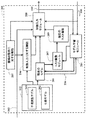
図1Bは、本発明の1つの実施の形態による制御システム101の一般的な構造を示している。制御システム101は、コントローラのモジュールを実行する少なくとも1つのプロセッサ130を備える。プロセッサ130は、モデル112および制約114を記憶するメモリ120に作動接続されている。本発明のいくつかの実施の形態の目的は、制約114を条件として機械112のモデルを用いて制御入力104を求めることである。いくつかの実施の形態の別の目的は、制約114が更新中満たされるように、機械のモデルを動作中に更新する(116)ことである。
FIG. 1B shows the general structure of a
図2Aは、本発明の1つの実施の形態による制御システム101の様々なモジュールのブロック図を示している。本発明のいくつかの実施の形態では、機械のMPCまたはモデルは、不確実性の少なくとも1つのパラメーターを含む。例えば、ロボットのアームのモデルは、物体をケアするアームの質量についての不確実性を含むことがある。列車の移動のモデルは、現在の天候条件における車輪とレールとの摩擦についての不確実性を含むことがある。いくつかの実施の形態では、制御システム101は、制御の不確実性を求めるのに用いられる。
FIG. 2A shows a block diagram of various modules of
いくつかの実施の形態では、機械のモデルは、モデル112のパラメーター間の関係を規定する公称モデル202と、モデル112および/または公称モデル202の少なくとも1つのパラメーターの値の範囲を規定する不確実性モデル203とを含む。例えば、公称モデルのパラメーターは、当該パラメーターのデフォルト値を用いることができる。例えば、公称モデル202は、理想的な条件における機械の運動を記述することができる。しかしながら、機械は、摩耗、外部動作、時間および天候に起因した変動、製造プロセスにおける不完全性に起因した正確に知られていない物理量、または測定誤差等の外部の影響を受け、したがって、機械の実際の運動は、公称モデルのものと正確に同じではない。例えば、1つの実施の形態は、公称モデルから開始して、機械状態値のシーケンスの観点から、現在のモデルが観察された機械の運動と一致するまで、現在のモデルを反復的に更新する。
In some embodiments, the model of the machine includes a
機械量のうちのいくつかは、機械の動作に対する制約205によって規定される所望の範囲内に留まる必要がある。本発明のいくつかの実施の形態は、制御入力に対する制約206を、不確実性モデル203を考慮に入れて、機械の動作に対する制約205から求めることができるという付加的な認識に基づいている。例えば、制御入力に対する制約206は、制約206を満たす制御入力104によって制御される機械102が、不確実性モデル203によって規定された許容可能な範囲内にあるモデルのパラメーターの値の全ての変動について制約206を満たすことを保証するように求められる。
Some of the machine quantities need to stay within the desired range defined by the
いくつかの実施の形態では、制約206は、オフラインで求められ、制約205は、機械の制御に用いられない。いくつかの実施の形態では、制約206は、機械を制御する少なくともいくつかの制約205と組み合わせて用いられる。
In some embodiments,
いくつかの実施の形態では、制御入力104は、当該制御入力に対する制約206を条件としたコスト関数209の最適化に基づいて求められる。制約206は、制御の実現可能性を保証するので、いくつかの実施の形態は、機械の動作の目的を達成する制御と、機械のモデルのパラメーターの不確実性を低減する割合を増加させる制御との間のトレードオフのための種々の項をコスト関数に含む。
In some embodiments, control
例えば、コスト関数は、動作の目的に従って制御入力の第1の値を求める第1の項を含むことができ、機械の現在の状態と、機械のモデルを用いて推定された状態との間の相違を縮小する制御入力の第2の値を求める第2の項を含み、そのため、最適化は、これらの第1の項および第2の項の組み合わせを最適化し、コスト関数を更新することは、この組み合わせにおける第2の項の重みを変化させることを含む。 For example, the cost function may include a first term for determining a first value of the control input according to the purpose of the operation, between the current state of the machine and the state estimated using the model of the machine It includes a second term which determines a second value of the control input which reduces the difference, so that the optimization optimizes the combination of these first and second terms and updates the cost function , Changing the weight of the second term in this combination.
したがって、いくつかの実施の形態では、制御システム101の様々なモジュールは、異なる制御目的について異なる項を含むコスト関数の最適化を用いて、機械の公称モデルおよび不確実性モデルによって規定された値の範囲内で機械のモデルのパラメーターを更新しながら、機械の動作の目的を満たす機械の制御を達成する。
Thus, in some embodiments, the various modules of the
制御システムは、機械のモデルを記憶するメモリ120と、コントローラのモジュールを実行するプロセッサ130とを備える。モジュールは、現在のコスト関数209を最適化することによって現在の反復中に制御する現在の制御入力104を求める制御入力モジュール208を含む。この制御入力モジュールは、現在の制御入力に対する制約206を条件として、機械の現在のモデル201を用いて現在のコスト関数を最適化する。
The control system comprises a
制御システムは、機械の現在のモデル201を求めるモデル学習モジュール204も備える。このモデル学習モジュールは、現在のモデルのパラメーターの現在の値が、公称モデル202および不確実性モデル203によって規定された値の範囲を有するとともに、機械の以前のモデルを用いて以前のコスト関数を最適化することによって以前の反復の間に求められた以前の制御入力を用いて制御した結果得られた機械の現在の状態106と、機械の以前のモデルを用いて推定された推定状態216との間の相違を縮小するようになっている。
The control system also comprises a
コントローラは、現在のコスト関数209を求めるコスト関数モジュール207も備える。例えば、コスト関数モジュールは、以前のモデルと現在のモデルとの間の相違を用いて以前のコスト関数を更新し、現在のコスト関数を生成する。制御のステップは、反復的に実行されるので、現在のモデルおよび現在のコスト関数は、後続の反復については以前のモデルおよび以前のコスト関数になる。例えば、以前のモデル、以前のコスト関数、および以前の制御入力は、以前の反復においては、現在のモデル、現在のコスト関数、および現在の制御入力として求められる。
The controller also comprises a
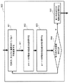
図2Bは、制御システム101のモジュールによって実行される方法のブロック図を示している。本方法は、コスト関数の最適化に基づいて機械のモデルを用いて求められた制御入力を用いて、機械の動作を反復的に制御する(270)。本方法は、機械の以前のモデルを用いて以前のコスト関数を最適化することによって以前の反復について求められた以前の制御入力を用いた制御の結果から得られる機械の現在の状態を求める(210)。
FIG. 2B shows a block diagram of a method performed by a module of
本方法は、測定された現在の状態と、機械の以前のモデルを用いて推定された状態との間の相違を縮小する機械の現在のモデルを、この現在のモデルのパラメーターの現在の値が上記値の範囲を有するように調整し(220)、以前のモデルと現在のモデルとの間の相違に基づいてコスト関数を更新する(230)。この更新230は、機械の動作の目的を達成する制御と、機械のモデルのパラメーターの不確実性を低減する割合を増加させる制御との間のトレードオフを提供する。
The method reduces the difference between the measured current state and the state estimated using the previous model of the machine, the current model of the machine, the current values of the parameters of this current model are Adjust to have the above range of values (220) and update the cost function based on the difference between the previous model and the current model (230). This
いくつかの実施の形態では、コスト関数は、動作の目的に従って制御入力の第1の値を求める第1の項を含むとともに、機械の現在の状態と機械のモデルを用いて推定された状態との間の相違を縮小する制御入力の第2の値を求める第2の項を含み、最適化は、第1の項および第2の項の組み合わせを最適化する。それらの実施の形態では、コスト関数は、その組み合わせにおける第2の項の重みを変化させることによって更新される。例えば、以前のモデルと現在のモデルとの間の相違が小さいほど、組み合わせにおける第2の項の重みは、低減される。 In some embodiments, the cost function includes a first term that determines a first value of the control input according to the purpose of the operation, and a state estimated using the current state of the machine and the model of the machine The optimization optimizes the combination of the first term and the second term, comprising a second term for determining a second value of the control input which reduces the difference between. In those embodiments, the cost function is updated by changing the weight of the second term in the combination. For example, the smaller the difference between the previous model and the current model, the lower the weight of the second term in the combination.
次に、本方法は、現在のモデルおよび現在のコスト関数を用いて、現在の反復における制御のための現在の制御入力を求める(280)。例えば、本方法は、更新された現在のコスト関数および現在の機械モデルを用いて、現在の時刻から、少なくとも新たな機械状態の測定値を取得するのに十分な長さの将来の固定時間量の間の将来の入力のシーケンスを、予測された将来の機械状態および入力が制御入力に対する制約を満たすように求める(240)。機械の状態の新たな測定値を取得するのに必要とされる時間量に等しい継続期間の間の入力シーケンスの第1の部分は、現在の制御入力として機械に印加される(250)。機械の現在の状態、機械の現在のモデル、および機械への現在の制御入力に基づいて、機械の次の状態が求められ(260)、コントローラは、新たな状態測定値が受信されるまで待機する(270)。 Next, the method determines 280 current control inputs for control in the current iteration using the current model and the current cost function. For example, the method may use the updated current cost function and the current machine model to obtain, from the current time, at least a future fixed time amount long enough to obtain a measurement of the new machine state. The sequence of future inputs during is determined 240 such that the predicted future machine states and inputs satisfy constraints on control inputs. A first portion of the input sequence for a duration equal to the amount of time required to obtain a new measurement of the machine's condition is applied to the machine as the current control input (250). The next state of the machine is determined 260 based on the current state of the machine, the current model of the machine, and the current control inputs to the machine, and the controller waits until a new state measurement is received. (270).
不確実性モデリング
本発明のいくつかの実施の形態は、モデルのパラメーターの真の値が不確実であっても、モデルのパラメーターの不確実性が既知の範囲内にあるという認識に基づいている。例えば、列車の質量は、空の列車および一杯に荷を積んだ列車の値の範囲内とすることができる。同様に、モデルのパラメーターの値に対する外乱には、限界が存在するとすることができる。不確実性モデル203は、公称モデルおよび不確実性モデルの組み合わせを用いてMPCの機械の現在のモデルを求めることができるように、モデルの少なくとも1つのパラメーターの可能な値の範囲を表す。
Uncertainty Modeling Some embodiments of the present invention are based on the recognition that even if the true values of the parameters of the model are uncertain, the uncertainty of the parameters of the model is within the known range . For example, the mass of the train can be in the range of values for empty and fully loaded trains. Similarly, there can be a limit on the disturbance to the value of the parameters of the model. The
図3Aは、上記認識の原理を視覚化した座標系320に配置された一例示のポリトープ310を示している。座標系320は、通常、不確実性を有するモデルのパラメーターの低次元系である。例えば、モデルが、不確実性を有する4つのパラメーターを含む場合、座標系320は、4次元であり、パラメーターの組み合わせの新たな値、例えば、値333、335、337がポリトープ310内で選択されるように、パラメーターのそれぞれにつき、1つの次元322、324、326、および328を有する。
FIG. 3A shows an
例えば、所与の機械状態、入力、および不確実性の組み合わさった影響を表す外乱dの連立差分方程式によって、等時間間隔のサンプリング時点における機械の運動を記述する関数は、以下の式となる。

![]()
![]()
![]()
![]()
例えば、値の範囲Dは、機械質量の最小値および最大値、外力の最小値および最大値によって求めることができる。同様に、入力および状態の範囲は、速度、位置、電圧、またはトルクの最小値および最大値によって求めることができる。 For example, the range of values D can be determined by the machine mass minimum and maximum values, the external force minimum and maximum values. Similarly, the range of inputs and states can be determined by the minimum and maximum values of speed, position, voltage or torque.
いくつかの実施の形態は、fおよびDに基づいて、それぞれ
![]()
![]()
![]()
![]()
![]()
![]()
![]()
![]()
式(4)における線形モデルは、例えば、Dによって許容されるベクトルdを形成するパラメーターおよび/またはそれらの組み合わせの最大値および最小値を選ぶことによって求めることができる。 The linear model in equation (4) can be determined, for example, by choosing the maximum and minimum values of the parameters forming vector d allowed by D and / or combinations thereof.
図3Bは、機械の状態を推定する際の、式(4)によって求められたモデルのパラメーターの不確実性の影響の概略図を示している。機械の現在の状態x301および制御入力が与えられると、機械の次の状態は、機械のモデルのパラメーターのdの種々の可能な値について、集合302内で変動する可能性がある。例えば、ベクトルdの特定の値に応じて、状態301は、制御入力の同じ値について集合302内で異なる状態310に遷移する可能性がある。
FIG. 3B shows a schematic view of the effect of the uncertainty of the parameters of the model determined by equation (4) in estimating the state of the machine. Given the current state of the machine x 301 and the control input, the next state of the machine may fluctuate within the
本発明のいくつかの実施の形態では、不確実性モデルは、公称モデルおよび不確実性モデルの組み合わせが、加法性外乱の凸結合を有する線形モデルの凸結合303に含まれるように拡張される。例えば、W=0のとき、式(4)のモデルは、有界多面体、すなわちポリトープである集合303によって集合302を過剰近似する。ここで、頂点304は、以下の式から求められる。
![]()
![]()
![]()
![]()
式(4)に基づいて、全てが
![]()
![]()
![]()
![]()
機械への制御入力に対する制約
本発明のいくつかの実施の形態は、機械の運動に対する制約が、所定の範囲内のモデルのパラメーターの値の全ての変動について、機械の動作中満たされることを保証するために、状態の実現可能領域
![]()
![]()
![]()
![]()
本発明のいくつかの実施の形態は、本明細書において制御入力に対する制御不変制約と呼ばれる制御入力に対するそのような制約を求めて用い、本明細書において状態の制御不変部分集合と呼ばれる状態の実現可能領域
![]()
![]()
図4Aは、本発明の実施の形態による、機械の動作に対する様々な制約によって規定された状態の制御不変部分集合の2次元投影410の一例を示している。通常、この実現可能領域は、動作に対する制約に対応する複数の次元に沿って、1次不等式によって表される超平面によって決定された多次元ポリトープである。
FIG. 4A illustrates an example of a two-
後退ホライズン制御の性質に起因して、ある特定のホライズンの解が存在することは、それだけで、後続のホライズンの解が存在することを保証するものではない。例えば、機械の状態および基準軌道の状態420は、1つの反復にとって最適かつ実現可能である可能性があるが、コントローラが次の反復中に取ることが可能な全ての制御動作421〜424は、機械の状態を実現可能領域410の外部に持っていく可能性がある。
Due to the nature of receding horizon control, the presence of a particular horizon solution by itself does not guarantee that a subsequent horizon solution exists. For example, while the state of the machine and the
本発明のいくつかの実施の形態は、実現可能領域の制御不変部分集合415を、その制御不変部分集合内の機械の任意の状態から、基準軌道の既知の将来の状態または基準軌道の全ての許容可能な将来の状態について、その部分集合内に機械の状態を維持する制御入力が存在するように選択することが可能であるというさらに別の認識に基づいている。例えば、部分集合415内およびコントローラが実行することができる全ての可能な制御入力431〜434内の状態430等の任意の状態について、機械および基準の状態を部分集合415内に維持する少なくとも1つの制御入力434が存在する。この場合、部分集合415は、制御不変部分集合である。
Some embodiments of the present invention control the
いくつかの実施の形態は、制御不変部分集合内の状態ごとに、式(5)による全ての可能な状態値について、機械の状態を制御不変部分集合内に維持する少なくとも1つの制御動作が存在するように、式(4)のモデルの状態の制御不変部分集合を求める。 Some embodiments have, for each state in the control invariant subset, at least one control action that maintains the state of the machine in the control invariant subset for all possible state values according to equation (5) The control invariant subset of the state of the model of equation (4) is determined as follows.
図4Bは、機械の状態の実現可能領域401と、
![]()
![]()
図5は、本発明の1つの実施の形態による実現可能領域
![]()
![]()
![]()
![]()
後方可到達領域計算は、現在の集合
![]()
![]()
![]()
![]()
![]()
![]()
![]()
![]()
![]()
![]()
![]()
![]()
![]()
![]()
503において、以前の集合
![]()
![]()
図6は、1つの実施の形態による状態の以前の集合を求める(502)一例示の実施の態様のブロック図を示している。この実施の形態は、パラメーターの全ての値について現在の集合内にある更新された状態を生成する状態−入力対を特定し(601)、これらの状態入力対を状態値に投影する(602)。すなわち、この実施の形態は、そのような状態−入力対のうちの少なくとも1つに属する状態を特定する。 FIG. 6 shows a block diagram of an exemplary implementation that determines 502 a prior set of states according to one embodiment. This embodiment identifies state-input pairs that generate updated states that are in the current set for all values of the parameter (601) and projects these state input pairs to state values (602) . That is, this embodiment identifies states that belong to at least one of such state-input pairs.
図7は、1次不等式が集合
![]()
![]()
![]()
![]()
![]()
![]()
![]()
![]()
![]()
![]()
次に、本方法は、これらの最悪の場合の外乱の影響分だけ現在の集合を縮小して(702)、
![]()
![]()
![]()
![]()
![]()
![]()
安定性制約
本発明のいくつかの実施の形態では、制御入力に対する制約は、公称モデルおよび不確実性モデルによって規定された機械のモデルのパラメーターの全ての値について、機械の状態を目標値に収束させる安定性制約を含む。1つの実施の形態では、これらの安定性制約は、機械の制御リアプノフ関数を含む。例えば、式(4)のモデルの制御リアプノフ関数(CLF)は、以下の実現可能値低減を満たす関数νである。
![]()
![]()
いくつかの実施の形態では、制御リアプノフ関数νは、制御不変である。本明細書において規定されているように、有効な不変制御リアプノフ関数は、例えば、式(4)のモデルについて求められた制御不変部分集合Cxの内部の全てのxについて、Cu(x)の内部に制御入力uが存在するような制御リアプノフ関数、すなわち、式(11)が満たされるように制御不変制約を満たす制御リアプノフ関数である。 In some embodiments, the control Lyapunov function 制 御 is control invariant. As defined herein, valid invariant control Lyapunov functions are, for example, C u (x) for all x within the control invariant subset C x determined for the model of equation (4). A control Lyapunov function such that there is a control input u inside, that is, a control Lyapunov function that satisfies a control invariant constraint such that equation (11) is satisfied.
図8は、本発明の1つの実施の形態による制御システムの不変制御リアプノフ関数を求める方法を示している。本方法は、候補のCLFを生成し(801)、この候補のCLFの状態の部分集合を、式(11)が有効であるように
![]()
![]()
図9は、ν(x)=||Px||∞である1つの実施の形態による、候補のリアプノフ関数の状態の部分集合を求める(802)方法のブロック図を示している。ここで、Pは、np個の行を有する無限ノルム制御リアプノフ関数を記述した行列である。この実施の形態は、行列Pのこれまでに選択されていない行911を選択し(901)、正の条件σ=+1について、不等式
次に、この実施の形態は、負の条件σ=−1について、行911に関係した部分集合の凸成分を求め(903)、−1は、(12)がこの時はσ=−1で満たされるようなuおよびεが存在するようにxの集合として計算される。全ての行が選択されると、全ての凸成分の和集合は、部分集合802を形成する。
Next, this embodiment determines the convex component of the subset related to
図10Aおよび図10Bは、有効な制御不変リアプノフ関数および無効な制御不変リアプノフ関数を判断するテストの説明図を示している。制御不変部分集合1001内の部分集合1002は、部分集合1003が候補のCLFの複数の凸成分1003の和集合である場合に有効である。図10Aでは、部分集合1002および1001が異なるので、CLFは、制御不変ではない。図10Bでは、部分集合1004が部分集合1001のエリア全体を包含することから、有効な部分集合1004を有する候補のCLFが部分集合1001について有効であるので、CLFは、制御不変である。
FIGS. 10A and 10B show an illustration of a test that determines valid control invariant Lyapunov functions and invalid control invariant Lyapunov functions. The
例えば、本発明の1つの実施の形態では、制御リアプノフ関数は、制御不変制約を満たす機械の全ての状態について実現可能値低減テストを満たす無限ノルム制御リアプノフ関数である。このテストは、無限ノルム制御リアプノフ関数を記述する行列の行を選択することと、制御不変制約を満たす機械の少なくとも1つの入力について無限ノルム制御リアプノフ関数を記述する行列の行に対する実現可能値低減を、正の条件および負の条件について満たす機械の状態の凸成分を求めることとを含むことができる。次に、この実施の形態は、これらの凸成分の和集合を求め、機械の状態の制御不変部分集合内の機械の全ての状態が凸成分の和集合に含まれることを検証する。 For example, in one embodiment of the present invention, the control Lyapunov function is an infinite norm control Lyapunov function that satisfies the realizable value reduction test for all states of the machine that satisfy the control invariant constraint. This test selects the rows of the matrix that describes the infinite norm control Lyapunov function and reduces the feasible values for the rows of the matrix that describes the infinite norm control Lyapunov function for at least one input of the machine that satisfies the control invariant constraint. And determining a convex component of the state of the machine that satisfies the positive and negative conditions. Next, this embodiment finds the union of these convex components and verifies that all states of the machine in the control invariant subset of machine states are included in the union of convex components.
モデル学習
1つの実施の形態では、機械の現在のモデル201は、公称モデル202に基づいて初期化される。この初期化では、一対の推定されたシステム行列
![]()
![]()
![]()
![]()
![]()
![]()
![]()
![]()
式(13)〜(14)における現在のモデルは、現在のモデルが、機械状態値のシーケンスの観点から、観察された機械の運動と一致するまで、入力104および状態106を用いて各時間ステップにおいて、そのそれぞれの集合内で更新される。
The current model in Equations (13)-(14) uses
1つの実施の形態では、このモデル更新の実施の態様は、(13)および(14)におけるモデルを、式(6)の頂点とWの頂点との線形結合であるとみなす。
![]()
![]()
この線形回帰モデルは、以下の形を取る。
線形回帰(17)は、この場合、いくつかの方法によって解くことができる。例えば、1つの実施の形態は、回帰の出力λ=[θ η]Tが、(15b)によるその許容された範囲内にあることを確実にするように修正された再帰的最小二乗(RLS)方法を用いる。 The linear regression (17) can in this case be solved in several ways. For example, one embodiment is a recursive least squares (RLS) modified to ensure that the output of the regression λ = [θ η] T is within its allowed range according to (15b) Use the method.
例えば、RLS方法は、以下の式の解を含むことができる。
図11は、本発明の1つの実施の形態に従って、修正されたRLSを用いて機械のモデルを更新し、機械の現在のモデルを生成するブロック図を示している。各ステップにおける修正されたRLSは、以前の入力および以前の状態を用いてリグレッサー行列Mを形成する(1101)とともに、現在の時間ステップの状態を測定値yとして用いる。修正されたRLSは、予測誤差共分散行列Ψを更新し(1102)、推定利得σを更新する(1103)。 FIG. 11 shows a block diagram of updating a model of a machine with a modified RLS to generate a current model of the machine, according to one embodiment of the present invention. The modified RLS in each step forms the regressor matrix M using the previous input and the previous state (1101), and uses the current time step state as the measurement value y. The modified RLS updates the prediction error covariance matrix Ψ (1102) and updates the estimated gain σ (1103).
次に、修正されたRLSは、パラメーターの第1の推定値
![]()
![]()
![]()
![]()
第2のパラメーター推定値は、複数の方法で求めることができる(1105)。例えば、1つの実施の形態は、まず、パラメーターの第1の推定値
![]()
![]()
![]()
![]()
![]()
![]()
![]()
![]()
![]()
![]()
コスト関数
本発明のいくつかの実施の形態では、コスト関数モジュール207は、公称コスト関数に基づいて現在のコスト関数209を初期化する。1つの実施の形態では、この公称コスト関数は、多面的であり、相反する目的を有する。例えば、コスト関数は、動作の目的に従って制御入力の第1の値を求める第1の項を含むことができるとともに、機械の現在の状態と、機械のモデルを用いて推定された状態との間の相違を縮小する制御入力の第2の値を求める第2の項を含み、そのため、最適化は、これらの第1の項および第2の項の組み合わせを最適化し、コスト関数を更新することは、この組み合わせにおける第2の項の重みを変化させることを含む。
Cost Function In some embodiments of the present invention,
1つの実施の形態では、コスト関数は、以下の式の形を取る。
1つの実施の形態では、関数Ltは、以下の式となる。
![]()
![]()
この情報汎関数は、未知のパラメーターベクトル(16)と関連付けられた情報の尺度である。この例には、トレース、行列式、および最大固有値が含まれる。情報汎関数が、コスト関数において優先権を与えられた場合、すなわち、γが大きい場合、機械の状態および入力には、モデル学習を改善する値に向けてバイアスがかけられ、そうでない場合、状態および入力には、機械の状態の調整に向けてバイアスがかけられる。 This information functional is a measure of the information associated with the unknown parameter vector (16). Examples of this include traces, determinants, and maximum eigenvalues. If the information functional is prioritized in the cost function, ie, γ is large, then the machine state and input are biased towards values that improve model learning, otherwise the state And the inputs are biased towards adjusting the state of the machine.
現在のコスト関数(19)は、残余誤差が大きいときは、コスト関数がモデル学習の改善のみを試みるように、各時間ステップにおいて、現在のモデルによって予測された状態および測定された実際の状態を用いて更新される。例えば、コスト関数の第2の項は、以前のモデルと現在のモデルとの間の相違の関数を含み、更新することは、以前のモデルと現在のモデルとの間の相違を求め、求められた相違を用いてコスト関数の第2の項を更新する。 The current cost function (19) states, at each time step, the state predicted by the current model and the actual state measured, such that when the residual error is large, the cost function only attempts to improve model learning. It is updated using. For example, the second term of the cost function includes a function of the difference between the previous model and the current model, and updating determines and determines the difference between the previous model and the current model. Update the second term of the cost function with the difference.
別の実施の形態では、コスト関数は、入力計算208に用いられる2つのコスト関数に分離される。ここで、第1のコスト関数は、モデル学習にのみ関係があり、すなわち、Ft=0およびLt=ψ(Pk)であり、第2のコスト関数は、機械の状態および第1のコスト関数の適用によって生成された入力シーケンスからの逸脱にペナルティを科すことの二元的な客観的取引規則を形成する。
In another embodiment, the cost function is split into two cost functions used for
入力計算
いくつかの実施の形態では、入力計算208は、以下の式の有限ホライズン数値最適化問題の形を取る。
![]()
![]()
![]()
![]()
代替の実施の形態では、問題(20)は、以下の2つのフェーズに分解される。
i)モデル学習フェーズ、例えば、Lt=ψ(Pk)。このフェーズは、予測されたパラメーター誤差共分散行列の情報汎関数を最小化する入力シーケンスを生成することのみに関係する。
ii)制御フェーズ。このフェーズは、機械を起点に調整する入力シーケンスを生成することのみに関係し、例えば、以下の式である。
![]()
i) Model learning phase, eg L t = L (P k ). This phase relates only to generating an input sequence that minimizes the information functional of the predicted parameter error covariance matrix.
ii) control phase. This phase relates only to the generation of an input sequence starting at the machine and is, for example:
![]()
モデル学習フェーズから制御フェーズへの切り替えは、現在のモデル201によって予測された状態と測定された実際の状態106との間の残余誤差に基づく。すなわち、この誤差が、設定された閾値未満であるとき、モデル学習は、もはや必要ではなく、制御フェーズへの切り替えが実施される。モデル学習フェーズへの戻し切り替えは、上記誤差が、設定された閾値を上回った場合に実施される。
The switch from model learning phase to control phase is based on the residual error between the state predicted by the
本発明の上記で説明した実施の形態は、数多くの方法のうちの任意のもので実施することができる。例えば、これらの実施の形態は、ハードウェア、ソフトウェア、またはそれらの組み合わせを用いて実施することができる。ソフトウェアで実施されるとき、ソフトウェアコードは、単一のコンピューターに設けられるかまたは複数のコンピューター間に分散されるかを問わず、任意の適したプロセッサまたはプロセッサの集合体上で実行することができる。そのようなプロセッサは、集積回路コンポーネントに1つまたは複数のプロセッサを有する集積回路として実施することができる。ただし、プロセッサは、任意の適した形式の回路部を用いて実施することができる。 The above-described embodiments of the present invention can be implemented in any of numerous ways. For example, these embodiments can be implemented using hardware, software, or a combination thereof. When implemented in software, the software code may be executed on any suitable processor or collection of processors, whether provided on a single computer or distributed among multiple computers . Such processors may be implemented as integrated circuits having one or more processors in integrated circuit components. However, a processor may be implemented using any suitable type of circuitry.
さらに、コンピューターは、ラックマウントコンピューター、デスクトップコンピューター、ラップトップコンピューター、ミニコンピューター、またはタブレットコンピューター等の複数の形態のうちの任意のもので具現化することができることが理解されるべきである。そのようなコンピューターは、エンタープライズネットワークまたはインターネット等のローカルエリアネットワークまたはワイドエリアネットワークを含む1つまたは複数のネットワークによって任意の適した形態に相互接続することができる。そのようなネットワークは、任意の適した技術に基づくことができ、任意の適したプロトコルに従って動作することができ、無線ネットワーク、有線ネットワーク、または光ファイバーネットワークを含むことができる。 Further, it should be understood that the computer can be embodied in any of several forms, such as a rack mount computer, desktop computer, laptop computer, mini computer, or tablet computer. Such computers may be interconnected in any suitable form by one or more networks, including a local area network such as an enterprise network or the Internet or a wide area network. Such networks can be based on any suitable technology, can operate according to any suitable protocol, and can include wireless networks, wired networks, or fiber optic networks.
また、本明細書において略述した様々な方法またはプロセスは、様々なオペレーティングシステムまたはプラットフォームのうちの任意の1つを用いる1つまたは複数のプロセッサ上で実行可能なソフトウェアとしてコード化することもできる。加えて、そのようなソフトウェアは、複数の適したプログラミング言語および/またはプログラミングツールもしくはスクリプティングツールのうちの任意のものを用いて記述することができる。 Also, the various methods or processes outlined herein may be encoded as software executable on one or more processors using any one of a variety of operating systems or platforms . In addition, such software can be described using any of a number of suitable programming languages and / or programming or scripting tools.
また、本発明の実施の形態は、方法として具現化することもできる。この方法の一例が提供されている。この方法の一部として実行されるステップは、任意の適した方法で順序付けることができる。したがって、例示されたものと異なる順序で動作が実行される実施の形態を構築することができ、これらの実施の形態は、いくつかの動作を、例示の実施の形態では順次的な作用として示されていても、同時に実行することを含むことができる。 The embodiments of the present invention can also be embodied as a method. An example of this method is provided. The steps performed as part of this method can be ordered in any suitable manner. Thus, embodiments may be constructed in which the operations are performed in a different order than that illustrated, which show several operations as sequential actions in the illustrated embodiment. Even if it does, it can include performing simultaneously.
Claims (15)
制御入力に対する制約、および前記機械の状態に対する制約を条件としたコスト関数の最適化に基づいて前記モデルを用いて求められた前記制御入力を用いて、前記機械の前記動作を反復的に制御することを含み、
前記動作は、複数の反復にわたってオンラインで制御され、
各反復は、
以前の反復について求められた以前の制御入力を用いて制御された前記機械の出力の測定結果を用いて、前記機械の現在の状態を求めることと、
前記機械の物理量を表す、前記機械動特性のモデルのパラメーターを更新し、前記現在の状態と、前記機械動特性の前記モデルを用いて推定された状態との間の予測誤差を縮小することと、
前記コスト関数を最適化し、制御入力を生成することと、
前記制御入力を用いて前記機械を制御することと、
を含み、
前記コスト関数は、前記機械の性能に関係する第1の項と、前記機械動特性の前記モデルの前記パラメーターの推定を改善する第2の項を含み、前記第2の項は、前記予測誤差の関数によって重み付けられ、前記第2の項は、前記機械動特性の前記モデルの予測されたパラメーター誤差共分散の情報汎関数を含み、
該方法は、方法を実行する格納された命令がプロセッサにより実行されるとき、前記命令は、前記方法の少なくともいくつかのステップを実行する、機械動特性のモデルに従って機械の動作を制御する方法。 A method of controlling the operation of a machine according to a model of mechanical dynamics, comprising:
The control operation of the machine is iteratively controlled using the control input determined using the model based on optimization of a cost function subject to constraints on control inputs and constraints on states of the machine Including
The operation is controlled online over multiple iterations,
Each iteration is
Determining the current state of the machine using measurements of the output of the machine controlled using previous control inputs determined for previous iterations;
Updating the parameters of the model of the machine dynamics characteristic representing the physical quantities of the machine and reducing the prediction error between the current state and the state estimated using the model of the machine dynamics. ,
Optimizing the cost function to generate a control input ;
Controlling the machine using the control input;
Including
The cost function includes a first term related to the performance of the machine and a second term for improving the estimation of the parameter of the model of the machine dynamics, the second term comprising the prediction error The second term includes an information functional of the predicted parameter error covariance of the model of the machine dynamics,
The method controls the operation of a machine according to a model of machine dynamics, wherein the instructions perform at least some steps of the method when stored instructions to perform the method are executed by a processor.
前記線形モデルの組み合わせベクトルおよび前記加法性外乱の組み合わせベクトルを求めることと、
前記線形モデルの前記組み合わせベクトルを前記線形モデルの前記凸結合に投影することと、
前記加法性外乱の前記組み合わせベクトルを前記加法性外乱の前記凸結合に投影することと、
を含む、請求項4に記載の方法。 Updating the model of the machine dynamics is:
Determining a combination vector of the linear model and a combination vector of the additive disturbance;
Projecting the combined vector of the linear model onto the convex combination of the linear model;
Projecting the combined vector of the additive disturbance onto the convex combination of the additive disturbance;
5. The method of claim 4, comprising
前記無限ノルム制御リアプノフ関数を記述する行列の行を選択することと、
前記制御不変制約を満たす前記機械の少なくとも1つの入力について前記無限ノルム制御リアプノフ関数を記述する前記行列の前記行に対する実現可能値低減を、正の条件および負の条件について満たす前記機械の前記状態の凸成分を求めることと、
前記凸成分の和集合を求めることと、
前記機械の前記状態の前記制御不変部分集合内の前記機械の全ての前記状態が前記凸成分の前記和集合に含まれることを検証することと、
からなる、請求項10に記載の方法。 The control Lyapunov function is an infinite norm control Lyapunov function that satisfies the realizable value reduction test for all the states of the machine that satisfy the control invariant constraint, and the realizable value reduction test is
Selecting the rows of the matrix describing the infinite norm control Lyapunov function;
The states of the machine of the machine which satisfy the feasible value reduction for the rows of the matrix describing the infinite norm control Lyapunov function for at least one input of the machine satisfying the control invariant constraint for positive and negative conditions Finding a convex component,
Obtaining a union of the convex components;
Verifying that all the states of the machine in the control invariant subset of the states of the machine are included in the union of the convex components;
11. The method of claim 10, comprising:
コスト関数の最適化に基づいて前記機械動特性の前記モデルを用いて求められた制御入力を用いて、前記機械の前記動作を反復的に制御すること、
を含み、前記最適化は、前記制御入力に対する制約、および前記機械の状態に対する制約を含む前記機械の前記動作に対する制御不変制約であって、該制御不変制約を満たす前記制御入力の任意の値が、前記機械の前記動作に対する制約を満たす状態の制御不変部分集合内に前記機械の状態を維持するように選択された前記制御入力に対する制御不変制約を条件とし、前記制御不変部分集合内の前記機械の任意の状態について、前記制御不変制約を満たすとともに、前記不確実性モデルによって規定された前記範囲内の前記モデルの前記パラメーターの全ての値について前記機械の前記状態を前記制御不変部分集合内に維持する、許容可能な制御入力が存在し、前記機械動特性の前記モデルの前記パラメーターは、前記機械の物理量を表し、前記動作は、複数の反復にわたってオンラインで制御され、各反復は、
以前の反復について求められた以前の制御入力を用いて制御された前記機械の出力の測定結果を用いて、前記機械の現在の状態を求めることと、
前記パラメーターの更新された値が前記値の範囲内にあるように前記機械動特性のモデルのパラメーターを更新し、前記現在の状態と、前記機械動特性の前記以前のモデルを用いて推定された状態との間の予測誤差を縮小することと、
前記コスト関数を最適化し、制御入力を生成することと、
前記制御入力を用いて前記機械を制御することと、
を含み、
前記コスト関数は、前記機械の性能に関係する第1の項と、前記機械動特性の前記モデルの前記パラメーターの推定を改善する第2の項を含み、前記第2の項は、前記予測誤差の関数によって重み付けられ、前記第2の項は、前記機械動特性の前記モデルの予測されたパラメーター誤差共分散の情報汎関数を含み、
該方法は、方法を実行する格納された命令がプロセッサにより実行されるとき、前記命令は、前記方法の少なくともいくつかのステップを実行する、機械動特性のモデルに従って機械の動作を制御する方法。 Machine operation according to said model of mechanical dynamics comprising a nominal model defining the relationship between parameters of the model of mechanical dynamics and an uncertainty model defining the range of values of at least one parameter of said model How to control,
Iteratively controlling the operation of the machine using control inputs determined using the model of the machine dynamics based on optimization of a cost function;
The optimization is a control invariant constraint on the operation of the machine including the constraint on the control input and the constraint on the state of the machine, any value of the control input satisfying the control invariant constraint being The machine in the control invariant subset, subject to a control invariant constraint on the control input selected to maintain the state of the machine in a control invariant subset of states satisfying the constraints on the operation of the machine, For any of the states of the machine, while satisfying the control invariant constraint, and for all values of the parameters of the model within the range defined by the uncertainty model, into the control invariant subset of the state of the machine There are acceptable control inputs to maintain, and the parameters of the model of the machine dynamics represent physical quantities of the machine; Serial operation is controlled online over multiple iterations, each iteration,
Determining the current state of the machine using measurements of the output of the machine controlled using previous control inputs determined for previous iterations;
The parameters of the mechanical dynamics model are updated such that the updated value of the parameter is within the range of values, and estimated using the current state and the previous model of the mechanical dynamics. Reducing the prediction error between states;
Optimizing the cost function to generate a control input ;
Controlling the machine using the control input;
Including
The cost function includes a first term related to the performance of the machine and a second term for improving the estimation of the parameter of the model of the machine dynamics, the second term comprising the prediction error The second term includes an information functional of the predicted parameter error covariance of the model of the machine dynamics,
The method, when the instructions stored for performing the method is executed by a processor, the instructions, to perform at least some steps of the method, a method of controlling the machine operation according to the model of the machine dynamics.
前記モデルのパラメーター間の関係を規定する公称モデルと、前記モデルの少なくとも1つのパラメーターの値の範囲を規定する不確実性モデルとを含む前記機械の前記モデル、および制御入力に対する制約と前記機械の状態に対する制約を含む前記機械の前記動作に対する前記制約を記憶するメモリと、
少なくとも1つのプロセッサであって、
前記機械の出力の測定結果を用いて、前記機械の現在の状態を求め、
前記機械動特性のモデルのパラメーターを更新し、前記現在の状態と、前記機械動特性の前記モデルを用いて推定された状態との間の予測誤差を縮小し、前記パラメーターの更新された値が前記値の範囲内になるようにし、
コスト関数を最適化して制御入力を生成し、前記コスト関数は、前記機械の性能に関係する第1の項と、前記機械動特性の前記モデルの前記パラメーターの推定を改善する第2の項を含み、前記第2の項は、前記予測誤差の関数によって重み付けられ、前記第2の項は、前記機械動特性の前記モデルの予測されたパラメーター誤差共分散の情報汎関数を含み、
前記制御入力を用いて前記機械を制御する、機械動特性のモデルに従って機械の動作を反復的に制御する制御システム。 A control system that repetitively controls the operation of a machine according to a model of mechanical dynamic characteristics, comprising:
Said model of said machine comprising a nominal model defining the relationship between parameters of said model and an uncertainty model defining the range of values of at least one parameter of said model, and constraints on control inputs and said machine A memory for storing the constraints on the operation of the machine including constraints on states;
At least one processor,
Using the measurement result of the output of the machine to determine the current state of the machine;
Update the parameters of the model of the mechanical dynamics, reduce the prediction error between the current state and the state estimated using the model of the mechanical dynamics, and updated values of the parameters are To be within the above range of values,
The cost function is optimized to generate control inputs, the cost function comprising a first term related to the performance of the machine and a second term for improving the estimation of the parameters of the model of the machine dynamics. Said second term being weighted by a function of said prediction error, said second term comprising an information functional of the predicted parameter error covariance of said model of said machine dynamics,
Control system wherein that control machines, iteratively control the machine operation according to the model of the machine dynamics by using the control input.
Applications Claiming Priority (2)
| Application Number | Priority Date | Filing Date | Title |
|---|---|---|---|
| US14/552,788 US9983554B2 (en) | 2014-11-25 | 2014-11-25 | Model predictive control with uncertainties |
| US14/552,788 | 2014-11-25 |
Publications (3)
| Publication Number | Publication Date |
|---|---|
| JP2016100009A JP2016100009A (en) | 2016-05-30 |
| JP2016100009A5 JP2016100009A5 (en) | 2018-10-18 |
| JP6513015B2 true JP6513015B2 (en) | 2019-05-15 |
Family
ID=56010109
Family Applications (1)
| Application Number | Title | Priority Date | Filing Date |
|---|---|---|---|
| JP2015218271A Active JP6513015B2 (en) | 2014-11-25 | 2015-11-06 | Method for controlling machine operation, and control system for repetitively controlling machine operation |
Country Status (2)
| Country | Link |
|---|---|
| US (1) | US9983554B2 (en) |
| JP (1) | JP6513015B2 (en) |
Families Citing this family (33)
| Publication number | Priority date | Publication date | Assignee | Title |
|---|---|---|---|---|
| US9625196B2 (en) * | 2014-06-09 | 2017-04-18 | Mitsubishi Electric Research Laboratories, Inc. | System and method for controlling of vapor compression system |
| US9764858B2 (en) * | 2015-01-07 | 2017-09-19 | Mitsubishi Electric Research Laboratories, Inc. | Model predictive control of spacecraft |
| EP3051367B1 (en) * | 2015-01-28 | 2020-11-25 | Honeywell spol s.r.o. | An approach and system for handling constraints for measured disturbances with uncertain preview |
| US10023300B2 (en) * | 2015-06-05 | 2018-07-17 | University Of North Dakota | Systems and methods for intelligent attitude determination and control |
| US20160378078A1 (en) * | 2015-06-29 | 2016-12-29 | Steffen Lamparter | Triggering an Auto-Tuning Function of a PID Controller |
| US10235818B2 (en) * | 2016-05-13 | 2019-03-19 | Ford Global Technologies, Llc | Adaptive vehicle control |
| US10309059B2 (en) * | 2016-09-23 | 2019-06-04 | Honeywell International Inc. | Method of designing model predictive control for cross directional flat sheet manufacturing processes to guarantee temporal robust stability and performance |
| DE102016224207A1 (en) * | 2016-12-06 | 2018-06-07 | Siemens Aktiengesellschaft | Method and control device for controlling a technical system |
| US20180275621A1 (en) | 2017-03-24 | 2018-09-27 | Mitsubishi Electric Research Laboratories, Inc. | Model Predictive Control with Uncertainties |
| EP3404497B1 (en) * | 2017-05-15 | 2021-11-10 | Siemens Aktiengesellschaft | A method and system for providing an optimized control of a complex dynamical system |
| US10732586B2 (en) | 2017-07-12 | 2020-08-04 | X Development Llc | Active disturbance compensation for physically changing systems |
| US20190056702A1 (en) * | 2017-08-21 | 2019-02-21 | General Electric Company | Model-based machine learing control system and method for tuning power production emissions |
| EP3682087B1 (en) | 2017-09-11 | 2023-11-29 | Services Pétroliers Schlumberger | Well planning system |
| US10613490B2 (en) | 2018-02-05 | 2020-04-07 | Mitsubishi Electric Research Laboratories, Inc. | Method and apparatus for preconditioned predictive control |
| US10860002B2 (en) * | 2018-03-19 | 2020-12-08 | Mitsubishi Electric Research Laboratories, Inc. | Receding horizon reference governor |
| US10619879B2 (en) * | 2018-03-21 | 2020-04-14 | Mitsubishi Electric Research Laboratories, Inc. | System and method for controlling operations of air-conditioning system |
| DE102018109785A1 (en) * | 2018-04-24 | 2019-10-24 | Vaillant Gmbh | Predictive control of a heat pump |
| US11321504B2 (en) * | 2018-05-09 | 2022-05-03 | Palo Alto Research Center Incorporated | Learning constitutive equations of physical components with constraints discovery |
| US11106189B2 (en) * | 2019-03-06 | 2021-08-31 | Mitsubishi Electric Research Laboratories, Inc. | System and method for data-driven control of constrained system |
| US10996639B2 (en) * | 2019-03-11 | 2021-05-04 | Mitsubishi Electric Research Laboratories, Inc. | Model predictive control of systems with continuous and discrete elements of operations |
| WO2020188328A1 (en) | 2019-03-15 | 2020-09-24 | 3M Innovative Properties Company | Method of performing a process and optimizing control signals used in the process |
| US11366697B2 (en) * | 2019-05-01 | 2022-06-21 | EMC IP Holding Company LLC | Adaptive controller for online adaptation of resource allocation policies for iterative workloads using reinforcement learning |
| US11586474B2 (en) | 2019-06-28 | 2023-02-21 | EMC IP Holding Company LLC | Adaptation of resource allocation for multiple workloads using interference effect of resource allocation of additional workloads on performance |
| US11676064B2 (en) * | 2019-08-16 | 2023-06-13 | Mitsubishi Electric Research Laboratories, Inc. | Constraint adaptor for reinforcement learning control |
| US11327801B2 (en) | 2019-08-29 | 2022-05-10 | EMC IP Holding Company LLC | Initialization of resource allocation for a workload characterized using a regression model |
| KR102231799B1 (en) * | 2019-10-11 | 2021-03-23 | 서울대학교산학협력단 | Stabilized method for nonlinear optimal control |
| US11868810B2 (en) | 2019-11-15 | 2024-01-09 | EMC IP Holding Company LLC | Resource adaptation using nonlinear relationship between system performance metric and resource usage |
| JP7288868B2 (en) * | 2020-01-31 | 2023-06-08 | 株式会社日立製作所 | MODEL UPDATE DEVICE AND METHOD AND PROCESS CONTROL SYSTEM |
| EP3904972B1 (en) | 2020-04-28 | 2023-09-06 | Siemens Aktiengesellschaft | Method and control device for controlling a technical system |
| US11334085B2 (en) * | 2020-05-22 | 2022-05-17 | The Regents Of The University Of California | Method to optimize robot motion planning using deep learning |
| US20210402980A1 (en) * | 2020-06-26 | 2021-12-30 | Mitsubishi Electric Research Laboratories, Inc. | System and Method for Data-Driven Reference Generation |
| EP4016404A1 (en) * | 2020-12-16 | 2022-06-22 | Fujitsu Limited | Method and apparatus for generating a control signal to control a device in accordance with a constrained hierarchy |
| US20220308530A1 (en) * | 2021-03-29 | 2022-09-29 | Mitsubishi Electric Research Laboratories, Inc. | System for Performing a Task According to a Reference Trajectory |
Family Cites Families (16)
| Publication number | Priority date | Publication date | Assignee | Title |
|---|---|---|---|---|
| US5659667A (en) | 1995-01-17 | 1997-08-19 | The Regents Of The University Of California Office Of Technology Transfer | Adaptive model predictive process control using neural networks |
| US6826521B1 (en) | 2000-04-06 | 2004-11-30 | Abb Automation Inc. | System and methodology and adaptive, linear model predictive control based on rigorous, nonlinear process model |
| US7797062B2 (en) * | 2001-08-10 | 2010-09-14 | Rockwell Automation Technologies, Inc. | System and method for dynamic multi-objective optimization of machine selection, integration and utilization |
| US6882889B2 (en) | 2002-12-02 | 2005-04-19 | United Technologies Corporation | Constrained dynamic inversion control algorithm |
| US7328074B2 (en) * | 2002-12-02 | 2008-02-05 | United Technologies Corporation | Real-time quadratic programming for control of dynamical systems |
| DE102004058238B4 (en) | 2003-12-03 | 2016-02-04 | Fisher-Rosemount Systems, Inc. | Adaptive, multivariable process control that uses model switching and attribute interpolation |
| EP1787172A1 (en) | 2004-08-27 | 2007-05-23 | Eidgenössische Technische Hochschule Zürich | System for controlling hydroelectric power plants |
| WO2006124716A2 (en) | 2005-05-13 | 2006-11-23 | Trustees Of Boston University | Fully automated control system for type 1 diabetes |
| US7447554B2 (en) | 2005-08-26 | 2008-11-04 | Cutler Technology Corporation | Adaptive multivariable MPC controller |
| US20070055392A1 (en) | 2005-09-06 | 2007-03-08 | D Amato Fernando J | Method and system for model predictive control of a power plant |
| US7599751B2 (en) | 2006-10-13 | 2009-10-06 | Cutler Technology Corporation | Adaptive multivariable MPC controller with LP constraints |
| US8126575B2 (en) | 2008-03-26 | 2012-02-28 | Fakhruddin T Attarwala | Universal model predictive controller |
| US8032236B2 (en) | 2008-09-30 | 2011-10-04 | Rockwell Automation Technologies, Inc. | Asymetrical process parameter control system and method |
| US20110016610A1 (en) | 2009-07-27 | 2011-01-27 | Steven Wieder | Sweatband with absorbent bamboo inner layer and related method of use |
| JP5569079B2 (en) * | 2010-03-24 | 2014-08-13 | Jfeスチール株式会社 | Model predictive control method and apparatus using online model identification |
| US8595162B2 (en) * | 2011-08-22 | 2013-11-26 | King Fahd University Of Petroleum And Minerals | Robust controller for nonlinear MIMO systems |
-
2014
- 2014-11-25 US US14/552,788 patent/US9983554B2/en active Active
-
2015
- 2015-11-06 JP JP2015218271A patent/JP6513015B2/en active Active
Also Published As
| Publication number | Publication date |
|---|---|
| JP2016100009A (en) | 2016-05-30 |
| US9983554B2 (en) | 2018-05-29 |
| US20160147203A1 (en) | 2016-05-26 |
Similar Documents
| Publication | Publication Date | Title |
|---|---|---|
| JP6513015B2 (en) | Method for controlling machine operation, and control system for repetitively controlling machine operation | |
| JP6359182B2 (en) | Method and system for controlling the operation of a machine | |
| Yan et al. | Data-driven load frequency control for stochastic power systems: A deep reinforcement learning method with continuous action search | |
| US20220146993A1 (en) | Machine learning method and machine learning device for learning fault conditions, and fault prediction device and fault prediction system including the machine learning device | |
| Dogru et al. | Reinforcement learning approach to autonomous PID tuning | |
| JP5737890B2 (en) | Method for learning the control and / or adjustment of a technical system with computer assistance | |
| JP7367233B2 (en) | System and method for robust optimization of reinforcement learning based on trajectory-centered models | |
| JP2016100009A5 (en) | ||
| EP3729209B1 (en) | Combined learned and dynamic control method | |
| Radanovic et al. | Learning to collaborate in markov decision processes | |
| CN115066695A (en) | Multi-objective reinforcement learning using target-specific action value functions | |
| US11543789B2 (en) | Reinforcement learning method, recording medium, and reinforcement learning system | |
| JP2020144483A (en) | Reinforcement learning method, reinforcement learning program, and reinforcement learning system | |
| JP7090734B2 (en) | Control system, control method and storage medium | |
| KR101234797B1 (en) | Robot and method for localization of the robot using calculated covariance | |
| US9946241B2 (en) | Model predictive control with uncertainties | |
| CN113597582A (en) | Tuning PID parameters using causal models | |
| Caarls et al. | Parallel online temporal difference learning for motor control | |
| Palunko et al. | Learning near‐optimal broadcasting intervals in decentralized multi‐agent systems using online least‐square policy iteration | |
| JP2021033767A (en) | Reinforcement learning method, reinforcement learning program, and reinforcement learning device | |
| JP2024044583A (en) | PLANT RESPONSE ESTIMATION APPARATUS, PLANT RESPONSE ESTIMATION METHOD, AND PROGRAM | |
| JPWO2020121494A1 (en) | Arithmetic logic unit, action determination method, and control program | |
| Nichols | A comparison of action selection methods for implicit policy method reinforcement learning in continuous action-space | |
| Liu et al. | Validating neural network-based online adaptive systems: A case study | |
| JP7159883B2 (en) | Reinforcement learning method, reinforcement learning program, and reinforcement learning device |
Legal Events
| Date | Code | Title | Description |
|---|---|---|---|
| A521 | Request for written amendment filed |
Free format text: JAPANESE INTERMEDIATE CODE: A523 Effective date: 20180905 |
|
| A621 | Written request for application examination |
Free format text: JAPANESE INTERMEDIATE CODE: A621 Effective date: 20180905 |
|
| A871 | Explanation of circumstances concerning accelerated examination |
Free format text: JAPANESE INTERMEDIATE CODE: A871 Effective date: 20180905 |
|
| A975 | Report on accelerated examination |
Free format text: JAPANESE INTERMEDIATE CODE: A971005 Effective date: 20181203 |
|
| A131 | Notification of reasons for refusal |
Free format text: JAPANESE INTERMEDIATE CODE: A131 Effective date: 20181211 |
|
| A521 | Request for written amendment filed |
Free format text: JAPANESE INTERMEDIATE CODE: A523 Effective date: 20190110 |
|
| TRDD | Decision of grant or rejection written | ||
| A01 | Written decision to grant a patent or to grant a registration (utility model) |
Free format text: JAPANESE INTERMEDIATE CODE: A01 Effective date: 20190312 |
|
| A61 | First payment of annual fees (during grant procedure) |
Free format text: JAPANESE INTERMEDIATE CODE: A61 Effective date: 20190409 |
|
| R150 | Certificate of patent or registration of utility model |
Ref document number: 6513015 Country of ref document: JP Free format text: JAPANESE INTERMEDIATE CODE: R150 |
|
| R250 | Receipt of annual fees |
Free format text: JAPANESE INTERMEDIATE CODE: R250 |
|
| R250 | Receipt of annual fees |
Free format text: JAPANESE INTERMEDIATE CODE: R250 |
|
| R250 | Receipt of annual fees |
Free format text: JAPANESE INTERMEDIATE CODE: R250 |