JP6511050B2 - Alignment system for aligning an imaging device with a tracking device, imaging system, intervention system, alignment method, operation method of imaging system, alignment computer program, and imaging computer program - Google Patents
Alignment system for aligning an imaging device with a tracking device, imaging system, intervention system, alignment method, operation method of imaging system, alignment computer program, and imaging computer program Download PDFInfo
- Publication number
- JP6511050B2 JP6511050B2 JP2016528387A JP2016528387A JP6511050B2 JP 6511050 B2 JP6511050 B2 JP 6511050B2 JP 2016528387 A JP2016528387 A JP 2016528387A JP 2016528387 A JP2016528387 A JP 2016528387A JP 6511050 B2 JP6511050 B2 JP 6511050B2
- Authority
- JP
- Japan
- Prior art keywords
- image
- alignment
- location
- imaging
- representation
- Prior art date
- Legal status (The legal status is an assumption and is not a legal conclusion. Google has not performed a legal analysis and makes no representation as to the accuracy of the status listed.)
- Active
Links
- 238000003384 imaging method Methods 0.000 title claims description 142
- 238000000034 method Methods 0.000 title claims description 44
- 238000004590 computer program Methods 0.000 title claims description 22
- 238000001514 detection method Methods 0.000 claims description 59
- 239000003550 marker Substances 0.000 claims description 54
- 238000013152 interventional procedure Methods 0.000 claims description 13
- 230000009466 transformation Effects 0.000 claims description 8
- 230000014509 gene expression Effects 0.000 claims description 7
- 230000003287 optical effect Effects 0.000 claims description 5
- 230000004044 response Effects 0.000 description 11
- 230000004807 localization Effects 0.000 description 7
- 239000000835 fiber Substances 0.000 description 6
- 230000011218 segmentation Effects 0.000 description 5
- 238000002679 ablation Methods 0.000 description 4
- 238000013459 approach Methods 0.000 description 4
- 230000001419 dependent effect Effects 0.000 description 4
- 210000003484 anatomy Anatomy 0.000 description 3
- 230000007423 decrease Effects 0.000 description 3
- 239000013307 optical fiber Substances 0.000 description 3
- 238000002591 computed tomography Methods 0.000 description 2
- 238000010191 image analysis Methods 0.000 description 2
- 230000033001 locomotion Effects 0.000 description 2
- 238000002595 magnetic resonance imaging Methods 0.000 description 2
- 238000004458 analytical method Methods 0.000 description 1
- 230000008901 benefit Effects 0.000 description 1
- 230000008859 change Effects 0.000 description 1
- 238000004891 communication Methods 0.000 description 1
- 238000012937 correction Methods 0.000 description 1
- 230000003247 decreasing effect Effects 0.000 description 1
- 238000003708 edge detection Methods 0.000 description 1
- 230000005672 electromagnetic field Effects 0.000 description 1
- 238000003780 insertion Methods 0.000 description 1
- 230000037431 insertion Effects 0.000 description 1
- 238000012986 modification Methods 0.000 description 1
- 230000004048 modification Effects 0.000 description 1
- 238000012544 monitoring process Methods 0.000 description 1
- 230000008569 process Effects 0.000 description 1
- 238000012545 processing Methods 0.000 description 1
- 230000009467 reduction Effects 0.000 description 1
- 238000004904 shortening Methods 0.000 description 1
- 239000007787 solid Substances 0.000 description 1
- 238000000844 transformation Methods 0.000 description 1
- 238000012285 ultrasound imaging Methods 0.000 description 1
Images


Classifications
-
- G—PHYSICS
- G06—COMPUTING; CALCULATING OR COUNTING
- G06T—IMAGE DATA PROCESSING OR GENERATION, IN GENERAL
- G06T7/00—Image analysis
- G06T7/70—Determining position or orientation of objects or cameras
- G06T7/73—Determining position or orientation of objects or cameras using feature-based methods
-
- G—PHYSICS
- G06—COMPUTING; CALCULATING OR COUNTING
- G06T—IMAGE DATA PROCESSING OR GENERATION, IN GENERAL
- G06T7/00—Image analysis
- G06T7/0002—Inspection of images, e.g. flaw detection
- G06T7/0012—Biomedical image inspection
-
- G—PHYSICS
- G06—COMPUTING; CALCULATING OR COUNTING
- G06T—IMAGE DATA PROCESSING OR GENERATION, IN GENERAL
- G06T7/00—Image analysis
- G06T7/20—Analysis of motion
- G06T7/246—Analysis of motion using feature-based methods, e.g. the tracking of corners or segments
-
- G—PHYSICS
- G06—COMPUTING; CALCULATING OR COUNTING
- G06T—IMAGE DATA PROCESSING OR GENERATION, IN GENERAL
- G06T7/00—Image analysis
- G06T7/30—Determination of transform parameters for the alignment of images, i.e. image registration
- G06T7/33—Determination of transform parameters for the alignment of images, i.e. image registration using feature-based methods
-
- G—PHYSICS
- G06—COMPUTING; CALCULATING OR COUNTING
- G06T—IMAGE DATA PROCESSING OR GENERATION, IN GENERAL
- G06T7/00—Image analysis
- G06T7/60—Analysis of geometric attributes
-
- G—PHYSICS
- G06—COMPUTING; CALCULATING OR COUNTING
- G06T—IMAGE DATA PROCESSING OR GENERATION, IN GENERAL
- G06T7/00—Image analysis
- G06T7/70—Determining position or orientation of objects or cameras
- G06T7/73—Determining position or orientation of objects or cameras using feature-based methods
- G06T7/75—Determining position or orientation of objects or cameras using feature-based methods involving models
-
- G—PHYSICS
- G06—COMPUTING; CALCULATING OR COUNTING
- G06T—IMAGE DATA PROCESSING OR GENERATION, IN GENERAL
- G06T2200/00—Indexing scheme for image data processing or generation, in general
- G06T2200/04—Indexing scheme for image data processing or generation, in general involving 3D image data
-
- G—PHYSICS
- G06—COMPUTING; CALCULATING OR COUNTING
- G06T—IMAGE DATA PROCESSING OR GENERATION, IN GENERAL
- G06T2200/00—Indexing scheme for image data processing or generation, in general
- G06T2200/24—Indexing scheme for image data processing or generation, in general involving graphical user interfaces [GUIs]
-
- G—PHYSICS
- G06—COMPUTING; CALCULATING OR COUNTING
- G06T—IMAGE DATA PROCESSING OR GENERATION, IN GENERAL
- G06T2207/00—Indexing scheme for image analysis or image enhancement
- G06T2207/10—Image acquisition modality
- G06T2207/10072—Tomographic images
-
- G—PHYSICS
- G06—COMPUTING; CALCULATING OR COUNTING
- G06T—IMAGE DATA PROCESSING OR GENERATION, IN GENERAL
- G06T2207/00—Indexing scheme for image analysis or image enhancement
- G06T2207/20—Special algorithmic details
- G06T2207/20092—Interactive image processing based on input by user
- G06T2207/20096—Interactive definition of curve of interest
-
- G—PHYSICS
- G06—COMPUTING; CALCULATING OR COUNTING
- G06T—IMAGE DATA PROCESSING OR GENERATION, IN GENERAL
- G06T2207/00—Indexing scheme for image analysis or image enhancement
- G06T2207/30—Subject of image; Context of image processing
- G06T2207/30004—Biomedical image processing
- G06T2207/30021—Catheter; Guide wire
-
- G—PHYSICS
- G06—COMPUTING; CALCULATING OR COUNTING
- G06T—IMAGE DATA PROCESSING OR GENERATION, IN GENERAL
- G06T2207/00—Indexing scheme for image analysis or image enhancement
- G06T2207/30—Subject of image; Context of image processing
- G06T2207/30204—Marker
Description
本発明は、イメージング装置を追跡装置と位置合わせするための位置合わせシステム、位置合わせ方法及び位置合わせコンピュータプログラムに関する。本発明は、更に、対象をイメージングするためのイメージングシステム、イメージング方法及びイメージングコンピュータプログラムに関する。本発明は更に、イメージングシステムを有する介入システムに関する。 The present invention relates to an alignment system, an alignment method and an alignment computer program for aligning an imaging device with a tracking device. The invention further relates to an imaging system, an imaging method and an imaging computer program for imaging an object. The invention further relates to an intervention system comprising an imaging system.
国際公開第2013/001388A1号公報は、身体ルーメンのライブの3次元画像を提供するシステムを開示している。システムは、身体ルーメンのX線画像を生成するX線システム、及び身体ルーメン内の可撓性の外科ツールの3次元形状を決定する光学的形状センシング装置(optical shape sensing、OSS)を有する。可撓性の外科ツールの決定された3次元形状及び身体ルーメンのX線画像は、特にX線画像の外科ツールのセグメント化に基づいて、互いに位置合わせされる。 WO 2013/001388 A1 discloses a system for providing a live three-dimensional image of a body lumen. The system has an x-ray system that generates an x-ray image of the body lumen, and an optical shape sensing (OSS) that determines the three-dimensional shape of the flexible surgical tool within the body lumen. The determined three-dimensional shape of the flexible surgical tool and the x-ray image of the body lumen are aligned with one another, in particular based on the segmentation of the surgical tool of the x-ray image.
米国特許出願公開第2010/0056904A1号公報は、挿入部位から患者内の処置部位までナビゲートされる、カテーテルのような介入器具を有する介入システムを開示している。ナビゲーションプロシージャの間、光学ファイバ部材を備える介入器具は、OSSを使用することによって追跡され、追跡されたロケーションは、患者の磁気共鳴画像内に表示される。OSSによって追跡される介入器具のロケーションを、患者の磁気共鳴画像上に表示するために、介入器具を追跡するOSS追跡システムと磁気共鳴画像を生成する磁気共鳴イメージングシステムとが、互いに位置合わせされる必要がある。位置合わせは、磁気共鳴画像内に、介入器具の光学ファイバ部材上の複数の既知のポイントをマーキングすることによって実施され、ここで既知のポイントは、磁気共鳴画像内において可視であるマーカを保持する。 US Patent Application Publication No. 2010/0056904 A1 discloses an interventional system having an interventional instrument such as a catheter that navigates from the insertion site to the treatment site in the patient. During the navigation procedure, the interventional instrument comprising the optical fiber member is tracked by using the OSS, and the tracked location is displayed in the patient's magnetic resonance image. An OSS tracking system tracking the interventional instrument and a magnetic resonance imaging system generating the magnetic resonance image are aligned with one another to display the location of the interventional instrument tracked by the OSS on the patient's magnetic resonance image There is a need. Alignment is performed by marking a plurality of known points on the optical fiber member of the interventional instrument in the magnetic resonance image, wherein the known points retain markers that are visible in the magnetic resonance image .
この介入プロシージャは、マーカを有する光学ファイバ部材を具備する特定の介入器具によってのみ実施されることができ、かかるマーカは、磁気共鳴画像において可視である。従って、介入プロシージャは、特定の介入器具にのみ制限される。 This interventional procedure can only be performed by certain interventional instruments comprising optical fiber members with markers, which are visible in magnetic resonance images. Thus, interventional procedures are limited only to specific interventional devices.
本発明の目的は、対象の画像を生成するイメージング装置を、対象のロケーションを追跡する追跡装置と位置合わせするための位置合わせシステム、位置合わせ方法、及び位置合わせコンピュータプログラムを提供することであり、それらにおいて、特定の対象に対する制限が低減される。更に、本発明の目的は、位置合わせシステムから得られる位置合わせ結果を使用する、対象をイメージングするためのイメージングシステム、イメージング方法、及びイメージングコンピュータプログラムを提供することである。本発明の他の目的は、イメージングシステムを有する介入システムを提供することである。 An object of the present invention is to provide an alignment system, an alignment method and an alignment computer program for aligning an imaging device for generating an image of an object with a tracking device for tracking the location of the object. In them, the restriction on specific objects is reduced. Furthermore, an object of the present invention is to provide an imaging system, an imaging method, and an imaging computer program for imaging an object, using the alignment result obtained from the alignment system. Another object of the present invention is to provide an intervention system having an imaging system.
本発明の第1の見地において、対象の画像を生成するイメージング装置を、対象の位置及び形状を決定することによりイメージング装置の視野内の対象のロケーションを追跡する追跡装置と位置合わせするように適応される位置合わせシステムであって、画像内の対象を検出する対象検出ユニットであって、a)対象が位置する画像内の任意の位置を示すために、ユーザがマーカを画像に加えることを可能にし、b)加えられたマーカに基づいて、画像内に対象の表現を提供する、ように適応される対象検出ユニットと、イメージング装置と追跡装置との位置合わせを規定する位置合わせパラメータを決定する位置合わせユニットであって、イメージング装置の視野内の対象の追跡されたロケーション及び画像内の対象の表現のロケーションに基づいて、位置合わせパラメータを決定するように適応される位置合わせユニットと、を有する位置合わせシステムが提示される。 In a first aspect of the invention, an imaging device for generating an image of an object is adapted to be aligned with a tracking device for tracking the location of the object in the field of view of the imaging device by determining the position and shape of the object Registration system for detecting objects in an image, wherein: a) a user can add markers to the image to indicate any position in the image where the object is located B) based on the added markers to determine the alignment parameters which define the alignment between the imaging device and the tracking device, the object detection unit adapted to provide a representation of the object in the image, and An alignment unit, the tracked location of an object in the field of view of an imaging device and the location of a representation of an object in an image Based on the alignment unit is adapted to determine the alignment parameters, alignment system having presented.
対象検出ユニットは、ユーザが、対象が位置する画像内の任意の位置を示すために、画像にマーカを加えることを可能にするように適応され、任意の位置におけるこれらのマーカは、画像内に対象の表現を提供するために使用され、位置合わせはその位置に基づいて行われるので、対象は、マーキングされる必要のある複数の既知の位置にマーカを保持する光学ファイバ部材を有する必要がない。ユーザは、ただ任意の位置においてマーカを画像に加えるだけでよく、これらの任意の位置は、例えば、対象に対して知られたものである必要はなく、同様に、対象は、既知の位置にマーカを有する必要がない。位置合わせは、ユーザにとって画像内で可視である任意の対象を用いて実施されることができ、それによって、位置合わせのために使用されることができる特定の対象への制限を低減することができる。 The object detection unit is adapted to allow the user to add markers to the image to indicate any position in the image where the object is located, these markers at any position in the image Because it is used to provide a representation of the object and alignment is done based on its position, the object does not have to have fiber optic members that hold the markers at multiple known positions that need to be marked . The user need only add markers to the image at any position, and these arbitrary positions do not have to be known, for example, to the object; likewise, the object is at a known position. There is no need to have a marker. Alignment can be performed with any object that is visible to the user in the image, thereby reducing the restriction on the specific objects that can be used for alignment. it can.
対象は、好適には、例えばカテーテル、ニードル、ガイドワイヤ等の介入器具のようなデバイスである。 The subject is preferably a device such as, for example, an interventional device such as a catheter, a needle, a guide wire or the like.
一実施形態において、イメージング装置は、視野の2次元投影画像を生成するように適応され、対象検出ユニットは、a)2次元投影画像内の対象を示すために、ユーザがマーカを2次元投影画像に加えることを可能にし、b)加えられたマーカに基づいて、2次元投影画像内に対象の表現を提供するように適応され、位置合わせユニットは、イメージング装置の視野内の対象の追跡されたロケーション及び2次元投影画像内の対象の表現のロケーションに基づいて、位置合わせパラメータを決定するように適応される。特に、イメージング装置は、それぞれ異なる投影方向に対応する少なくとも2つの2次元投影画像を生成するように適応され、対象検出ユニットは、a)ユーザが、それぞれ異なる2次元投影画像内に対象を示すために、2次元投影画像の各々にマーカを加えることを可能にし、b)加えられたマーカに基づいて、2次元投影画像内に対象の表現を提供する、ように適応され、位置合わせユニットは、イメージング領域の対象の追跡されたロケーション及び2次元投影画像における対象の表現のロケーションに基づいて、位置合わせパラメータを決定するように適応される。イメージング装置は、好適には、1又は複数の2次元X線投影画像を生成するように適応される。位置合わせパラメータが決定されたのち、個々の2次元投影画像が、実際の画像ではなく、もっと古いものであっても、対象の実際のロケーションが、個々の2次元投影画像に表示されることができる。従って、例えば、介入プロシージャの最中、対象が移動される間、実際の2次元投影画像が提供されることを要求することなく、この例では介入器具である対象のロケーションが、それぞれ異なる2次元投影画像に表示されることができる。 In one embodiment, the imaging device is adapted to generate a two-dimensional projection image of the field of view, and the object detection unit a) displays a marker of the user on the two-dimensional projection image to indicate the object in the two-dimensional projection image. And b) adapted to provide a representation of the object in the two-dimensional projection image based on the added marker, the registration unit is adapted to track the object in the field of view of the imaging device The alignment parameters are adapted to be determined based on the location and the location of the representation of the object in the two-dimensional projection image. In particular, the imaging device is adapted to generate at least two two-dimensional projection images corresponding to different projection directions, and the object detection unit a) for the user to indicate objects in different two-dimensional projection images To enable the addition of markers to each of the two-dimensional projection images, and b) providing a representation of the object in the two-dimensional projection image based on the added markers, the registration unit being adapted to: An alignment parameter is adapted to be determined based on the tracked location of the object in the imaging region and the location of the representation of the object in the two-dimensional projection image. The imaging device is preferably adapted to generate one or more two-dimensional x-ray projection images. After the registration parameters have been determined, the actual location of the object may be displayed in the individual two-dimensional projection images, even if the individual two-dimensional projection images are older than the actual image. it can. Thus, for example, during an interventional procedure, while the subject is being moved, the location of the subject, which in this example is the interventional instrument, is different each other without requiring that an actual two-dimensional projection image be provided. It can be displayed on the projection image.
追跡装置は、好適には、対象の3次元ロケーションを追跡するように適応され、位置合わせユニットは、2次元投影画像を生成するイメージング装置によって使用される投影ジオメトリを考慮して対象の追跡された3次元ロケーションの2次元投影を計算し、及び追跡装置によって規定される座標系とイメージング装置によって規定される座標系の間の空間変換を計算することによって、位置合わせパラメータを決定するように適応され、空間変換は、対象の追跡された3次元ロケーションの計算された2次元投影と、2次元投影画像内における対象の表現のロケーションとの間の偏差を最小にする。追跡されるロケーションは3次元であり、画像は2次元であるが、これは、位置合わせパラメータを比較的正確に決定することを可能にする。 The tracking device is preferably adapted to track the three-dimensional location of the object, and the registration unit is tracked of the object taking into account the projection geometry used by the imaging device generating the two-dimensional projection image Adapted to determine alignment parameters by calculating a two-dimensional projection of the three-dimensional location and calculating a spatial transformation between the coordinate system defined by the tracking device and the coordinate system defined by the imaging device Spatial transformation minimizes the deviation between the calculated two-dimensional projection of the tracked three-dimensional location of the object and the location of the representation of the object in the two-dimensional projection image. The tracked location is three dimensional and the image is two dimensional, which allows the registration parameters to be determined relatively accurately.
追跡装置は、OSSによって対象のロケーションを追跡するように適応され、位置合わせユニットは、OSSによって追跡されるイメージング装置の視野内の対象のロケーション及び画像内における対象の表現のロケーションに基づいて、位置合わせパラメータを決定するように適応されることが好ましい。OSSは、非常に正確に且つユーザによって容易に扱われることができるやり方で、対象のロケーションを追跡することを可能にする。例えば、対象のロケーションを追跡するために、電磁界のような付加の場を提供する必要はない。 The tracking device is adapted to track the location of the object by the OSS, and the registration unit is positioned based on the location of the object in the field of view of the imaging device tracked by the OSS and the location of the representation of the object in the image Preferably, it is adapted to determine alignment parameters. The OSS makes it possible to track the location of an object very accurately and in a way that can be easily handled by the user. For example, it is not necessary to provide an additional field such as an electromagnetic field to track the location of interest.
対象検出ユニットは、画像内における対象の表現として、加えられたマーカを提供するように適応されることができる。しかしながら、対象検出ユニットは更に、加えられたマーカに基づいて、表現を決定し、特に計算するように適応されることができる。例えば、対象が長めの対象である場合、対象検出ユニットは、加えられたマーカをラインによって接続することによって、画像内における対象の表現を決定するように適応されることができる。従って、対象は、加えられたマーカを接続する複数のラインセグメントによって表現されることができる。しかしながら、対象検出ユニットは、加えられたマーカに曲線をフィットさせることによって、画像内における対象の表現を決定するようにも適応されることができる。更に、対象検出ユニットは、加えられたマーカ及び画像の画像値に基づいて、画像内に対象の表現を提供するように適応されることができる。更に、画像内における対象の表現を提供する間に画像値を考慮することは、画像内における対象の位置及び形状により良くフィットする表現を与えることができ、それにより位置合わせの正確さを改善する。 The object detection unit can be adapted to provide the added marker as a representation of the object in the image. However, the object detection unit can also be adapted to determine and in particular to calculate a representation based on the added markers. For example, if the object is a longer object, the object detection unit can be adapted to determine the representation of the object in the image by connecting the added markers by a line. Thus, an object can be represented by a plurality of line segments connecting the added markers. However, the object detection unit can also be adapted to determine the representation of the object in the image by fitting the curve to the added markers. Furthermore, the object detection unit can be adapted to provide a representation of the object in the image based on the added markers and the image values of the image. Furthermore, considering the image values while providing a representation of the object in the image can provide a better fit representation to the position and shape of the object in the image, thereby improving the registration accuracy .
例えば、対象検出ユニットは、画像の画像値に基づいて、画像内の対象のロケーションを示すロケーション情報を決定し、加えられたマーカ及びロケーション情報に基づいて、画像内に対象の表現を提供するように適応されることができる。特に、対象検出ユニットは、画像内における対象のロケーションを示す、すなわち例えば画像内における長めの対象の空間的な走行を示すロケーション情報を生成するために、対象検出アルゴリズムを画像に適用するように適応されることができる。例えば、セグメント化アルゴリズムが、画像内の対象をセグメント化するために画像に適用されることができ、その場合、セグメント化される対象は、この例ではロケーション情報である。対象が位置する画像内の任意の位置を示す手動で加えられるマーカは、自動的に決定されるロケーション情報よりも信頼できるものであると考えられるので、対象検出ユニットは好適には、画像内の対象の表現の決定の最中、加えられるマーカがロケーション情報より重く加重されるように適応される。例えば、表現を決定するために、表現と加えられたマーカとの間の距離を短縮することに伴って減少し、画像値から決定されるロケーション情報によって示される画像内の対象のロケーションと表現との間の距離を短縮することに伴って減少する費用関数が用いられることができる。 For example, the object detection unit may determine location information indicating the location of the object in the image based on the image values of the image, and provide a representation of the object in the image based on the added marker and the location information Can be adapted to. In particular, the object detection unit is adapted to apply an object detection algorithm to the image in order to generate location information indicating the location of the object in the image, ie indicating for example the spatial travel of longer objects in the image. It can be done. For example, a segmentation algorithm can be applied to the image to segment objects in the image, in which case the object to be segmented is location information in this example. The object detection unit is preferably arranged in the image as a manually added marker indicating any position in the image where the object is located is considered to be more reliable than the automatically determined location information. During the determination of the representation of the object, the applied markers are adapted to be weighted more heavily than the location information. For example, as the distance between the representation and the added marker is reduced to determine the representation, the location and representation of the object in the image indicated by the location information determined from the image values and A cost function can be used that decreases with shortening the distance between
表現と加えられたマーカとの間の距離は、画像値から決定されるロケーション情報によって示されるロケーションと表現との間の距離よりも費用関数に大きく寄与することができる。対象検出ユニットは、費用関数を最小にすることによって表現を決定するように適応されることができる。 The distance between the representation and the added marker can contribute more to the cost function than the distance between the location indicated by the location information determined from the image values and the representation. The object detection unit can be adapted to determine the representation by minimizing the cost function.
対象検出ユニットは、画像内の対象のロケーションを示す、画像の画像値に基づき決定されたロケーション情報に依存して、加えられたマーカの位置を補正することによって、及びマーカの補正された位置に基づいて画像内に対象の表現を提供することによって、画像内に対象の表現を提供するように適応されることができる。例えば、画像領域が対象に対応する見込みを示す尺度であって、1又は複数の画素によって形成されることができる尺度が、ロケーション情報によって規定される画像領域及びユーザにより加えられたマーカによって規定される画像領域に適用されることができ、この場合、ロケーション情報によって規定される画像領域に適用される尺度と、ユーザにより加えられたマーカによって規定される画像領域に適用される尺度との間の差異が、予め規定された閾値より大きい場合、ユーザにより加えられたマーカの近傍に位置するシフトされたマーカがより小さい差異をもたらすかどうかが判定されることができる。そうである場合、シフトされたマーカが、ユーザにより加えられたマーカの代わりに使用されることができ、補正されたマーカとみなされることができる。このようにして、少なくとも1つのマーカが補正されることができ、画像内における対象の表現は、少なくとも1つの補正されたマーカ及び任意にはユーザにより更に加えられた補正されていないマーカに基づいて、提供されることができる。この理由は、補正されたマーカは、すでに最初に十分な正確さを伴って画像内における対象のロケーションを示すからであり、すなわち例えば、シフトされたマーカは、個々のマーカによって規定される画像領域に適用される尺度と、ロケーション情報によって規定される画像領域に適用される尺度との間のより小さい差異を与えないからである。尺度は、例えば血管らしさ(vesselness)応答でありうる。特にユーザがマーカを画像に単に雑に加えた場合、ロケーション情報に依存して加えられたマーカの位置を補正することは、位置合わせの正確さを一層改善することができ、この場合、画像内における対象の表現は、マーカの補正された位置に基づいて提供される。 The object detection unit is adapted to correct the position of the added marker depending on the location information determined based on the image values of the image, which indicate the location of the object in the image, and to correct the position of the marker. By providing a representation of the object in the image based on, it can be adapted to provide a representation of the object in the image. For example, a measure that indicates the likelihood that the image area corresponds to an object, and the measure that can be formed by one or more pixels is defined by the image area defined by the location information and the marker added by the user Can be applied to the image area, in this case, between the measure applied to the image area defined by the location information and the measure applied to the image area defined by the marker added by the user. If the difference is greater than a predefined threshold, it may be determined whether the shifted markers located in the vicinity of the marker added by the user will result in a smaller difference. If so, shifted markers can be used instead of markers added by the user and can be considered as corrected markers. In this way, at least one marker can be corrected and the representation of the object in the image is based on the at least one corrected marker and optionally also the uncorrected marker added by the user Can be provided. The reason for this is that the corrected markers already show initially the location of the object in the image with sufficient accuracy, ie for example the shifted markers are the image areas defined by the individual markers Because it does not give a smaller difference between the measure applied to and the measure applied to the image area defined by the location information. The measure may be, for example, a vesselness response. Correcting the position of the added marker depending on the location information can further improve the registration accuracy, in particular if the user simply adds the marker to the image in a mess. A representation of the object at is provided based on the corrected position of the marker.
イメージング装置は、それぞれ異なる投影方向に対応する少なくとも2つの2次元投影画像を提供するように適応されることができ、対象検出ユニットは、a)ユーザが、2次元投影画像のうち第1の画像内の対象を示すために、第1の画像にマーカを加えることを可能にし、b)加えられたマーカに基づいて第1の画像内に対象の第1の表現を提供し、2次元投影画像のうち第2の画像の画像値に基づいて第2の画像内に対象の第2の表現を提供する、ように適応されることができ、位置合わせユニットは、イメージング領域における対象の追跡されたロケーション並びに第1及び第2の画像内の対象の第1及び第2の表現のロケーションに基づいて、位置合わせパラメータを決定するように適応されることができる。例えば、対象検出ユニットは、第2の画像内の対象のロケーションを示すロケーション情報を決定するために、対象検出アルゴリズムを第2の画像の画像値に適用することができる。この対象検出アルゴリズムは、例えば第2の画像内の対象をセグメント化するセグメント化アルゴリズムであり、セグメント化された対象は、第2の画像内の第2の表現を規定するロケーション情報であるとみなされることができる。位置合わせパラメータの決定の最中、加えられたマーカに基づいて提供された第1の画像内の第1の表現は、第2の画像内の対象の第2の表現よりも一層好適であると考えられ、その理由は、ユーザ入力に基づく第1の表現が、第2の表現より信頼性が高いと考えられるからである。これは、位置合わせプロセスの最中、各投影画像において個々の投影画像内の対象の位置を示すマーカをユーザが加える必要なく、それぞれ異なる投影画像内の表現を考慮することを可能にする。 The imaging device may be adapted to provide at least two two-dimensional projection images corresponding respectively to different projection directions, wherein the object detection unit comprises: a) a user selects a first one of the two-dimensional projection images Allowing a marker to be added to the first image to indicate the object within, b) providing a first representation of the object within the first image based on the added marker, a two-dimensional projection image The method may be adapted to provide a second representation of the object in the second image based on the image values of the second image, the registration unit being tracked of the object in the imaging region The alignment parameters may be adapted to be determined based on the location and the location of the first and second representations of the object in the first and second images. For example, the subject detection unit may apply a subject detection algorithm to the image values of the second image to determine location information indicative of the location of the subject in the second image. The object detection algorithm is, for example, a segmentation algorithm that segments the object in the second image, and the segmented object is regarded as location information defining a second representation in the second image. It can be done. During the determination of the alignment parameters, the first representation in the first image provided based on the added markers is more suitable than the second representation of the object in the second image It is conceivable that the reason is that the first expression based on the user input is considered to be more reliable than the second expression. This allows the representation in different projection images to be taken into account without the user having to add markers indicating the position of the object in the individual projection images in each projection image during the registration process.
本発明の別の見地において、対象をイメージングするイメージングシステムであって、対象の位置及び形状を決定することによって、関心領域(ROI)の画像を生成するイメージング装置と、関心領域における対象のロケーションを追跡する追跡装置と、位置合わせパラメータを決定する請求項1に記載の位置合わせシステムと、対象の追跡されたロケーション及び決定された位置合わせパラメータに基づいて、関心領域の画像内の対象のロケーションを決定するロケーション決定ユニットと、を有するイメージングシステムが提示される。 In another aspect of the invention, an imaging system for imaging an object, the imaging device producing an image of a region of interest (ROI) by determining the position and shape of the object, and the location of the object in the region of interest The location of the object in the image of the region of interest based on the tracking device to be tracked, the alignment system according to claim 1 for determining the alignment parameter, and the tracked location of the object and the determined alignment parameter And a location determining unit for determining.
関心領域の画像内の対象のロケーションは、対象の追跡されたロケーション及び決定された位置合わせパラメータに基づいて決定されるので、関心領域の画像が、関心領域内の対象の実際のロケーションを表示する実際の画像である必要はない。事実、関心領域の画像は、より古い画像でもよく、この画像において、関心領域内の対象の実際のロケーションが、位置合わせパラメータ及び対象の実際に追跡されたロケーションに基づいて、表示されることができる。 Since the location of the object in the image of the region of interest is determined based on the tracked location of the object and the determined registration parameters, the image of the region of interest displays the actual location of the object in the region of interest It does not have to be an actual image. In fact, the image of the region of interest may be an older image, in which the actual location of the object in the region of interest is displayed based on the alignment parameters and the actually tracked location of the object it can.
本発明の他の見地において、介入プロシージャを実施するための介入器具と、請求項10に記載の介入器具をイメージングするためのイメージングシステムと、を有する介入システムが提示される。
In another aspect of the invention, an intervention system is presented comprising an interventional instrument for performing an interventional procedure and an imaging system for imaging the interventional instrument according to
本発明の別の見地において、対象の画像を生成するイメージング装置を、対象の位置及び形状を決定することによりイメージング装置の視野内の対象のロケーションを追跡する追跡装置と位置合わせするように適応される位置合わせ方法であって、対象検出ユニットによって画像の対象を検出するステップであって、対象検出ユニットが、a)ユーザが、対象が位置する画像内の任意の位置を示すために画像にマーカを加えることを可能にし、b)加えられたマーカに基づいて、画像内に対象の表現を提供する、ことを含むステップと、位置合わせユニットによって、追跡装置とイメージング装置との位置合わせを規定する位置合わせパラメータを決定するステップであって、位置合わせユニットが、イメージング装置の視野内の対象の追跡されたロケーション及び画像内の対象の表現のロケーションに基づいて位置合わせパラメータを決定する、ことを含むステップと、を有する位置合わせ方法が提示される。 In another aspect of the invention, an imaging device for generating an image of an object is adapted to be aligned with a tracking device for tracking the location of the object within the field of view of the imaging device by determining the position and shape of the object. Registration method, wherein the object detection unit detects an object of the image, the object detection unit a) marking the image on the image in order for the user to indicate an arbitrary position in the image where the object is located And b) providing a representation of the object in the image based on the added markers, and an alignment unit defining the alignment between the tracking device and the imaging device Determining alignment parameters, the alignment unit tracking an object within the field of view of the imaging device Determining the alignment parameter based on the location of the target expressions that are within location and image registration method having the steps comprising it is presented.
本発明の他の見地において、対象をイメージングするイメージング方法であって、イメージング装置によって、関心領域の画像を生成するステップと、追跡装置によって、対象の位置及び形状を決定することにより関心領域の対象のロケーションを追跡するステップと、請求項12に記載の位置合わせ方法によって位置合わせパラメータを決定するステップと、ロケーション画像生成ユニットによって、対象の追跡されたロケーション、関心領域の画像、及び決定された位置合わせパラメータに基づいて、関心領域の画像内の対象のロケーションを示すロケーション画像を生成するステップと、を含む方法が提示される。
In another aspect of the invention, an imaging method for imaging an object, comprising: generating an image of a region of interest by the imaging device; and determining the position and shape of the object by a tracking device. Tracking the location of the object, determining the alignment parameter by the alignment method according to
本発明の別の見地において、対象の位置及び形状を決定することによってイメージング装置の視野内の対象のロケーションを追跡する追跡装置と、対象の画像を生成するイメージング装置を位置合わせするように適応される位置合わせコンピュータプログラムであって、位置合わせコンピュータプログラムが位置合わせシステムを制御するコンピュータ上でランされるとき、請求項1に記載の位置合わせシステムに、請求項12に記載の位置合わせ方法の各ステップを実施させるプログラムコード手段を有する、位置合わせコンピュータプログラムが提示される。
In another aspect of the invention, it is adapted to align a tracking device which tracks the location of the object in the field of view of the imaging device by determining the position and shape of the object and the imaging device which generates the image of the object. An alignment computer program according to
本発明の他の見地において、対象をイメージングするイメージングコンピュータプログラムであって、イメージングコンピュータプログラムがイメージングシステムを制御するコンピュータ上でランされるとき、請求項10に記載のイメージングシステムに、請求項13に記載のイメージング方法の各ステップを実施させるプログラムコード手段を有する、イメージングコンピュータプログラムが提示される。
In another aspect of the invention, an imaging computer program for imaging an object, the imaging computer program being run on a computer controlling the imaging system, the imaging system according to
本発明の別の見地において、方法及びユーザインタフェースであって、イメージングシステムが、例えば、画像上に関心領域を配置し関心領域とインタラクトすること、2又はそれ以上の関心領域を配置しそれとインタラクトすること、又は画像内の選択された「候補」のポイントロケーション(例えば器具の先端のロケーション)の中から選択を行うこと、のような代替手法を使用して、位置合わせのためにユーザ情報を受け入れることを可能にすることによって、提供される位置合わせの使用を多くの異なるワークフローシナリオ及びユーザ嗜好にまで拡張する。 In another aspect of the invention, a method and user interface, wherein the imaging system, for example, places the region of interest on the image and interacts with the region of interest, places and interacts with two or more regions of interest Accept user information for alignment using an alternative approach such as selecting from among selected "candidate" point locations in the image (e.g. the location of the tip of the instrument) By extending the use of the provided alignment to many different workflow scenarios and user preferences.
請求項1に記載の位置合わせシステム、請求項10に記載のイメージングシステム、請求項11に記載の介入システム、請求項12に記載の位置合わせ方法、請求項13に記載のイメージング方法、請求項14に記載の位置合わせコンピュータプログラム、及び請求項15に記載のイメージングコンピュータプログラムは、従属請求項に記載の同様の及び/又は同一の好適な実施形態を有することが理解されるべきである。
An alignment system according to claim 1, an imaging system according to
本発明の好適な実施形態は、個々の独立請求項と従属請求項又は上述の実施形態との任意の組み合わせであってもよいことが理解されるべきである。 It should be understood that the preferred embodiments of the present invention may be any combination of the individual independent claims with the dependent claims or the embodiments described above.
本発明のこれら及び他の見地は、以下に記述される実施形態から明らかになり、それらを参照して説明される。 These and other aspects of the invention are apparent from and will be elucidated with reference to the embodiments described hereinafter.
図1は、介入システムの実施形態を概略的及び例示的に示す。介入システム1は、介入プロシージャを実施する介入器具33を有する。この実施形態において、介入器具33は、カテーテル制御ユニット15によって制御されるカテーテルである。カテーテル制御ユニット15及びカテーテル33は、例えば、患者テーブル26のような支持手段上に横たわる人25の心臓24内においてアブレーションプロシージャを実施するように適応されることができる。しかしながら、カテーテル33及びカテーテル制御ユニット15は、別の介入プロシージャを実施するように適応されることもできる。更に、介入システムは、ニードルのような別の介入器具を有することができる。この実施形態において、カテーテル33は無線周波数(RF)アブレーションプロシージャを適用するように適応され、カテーテル制御ユニット50は、RFエネルギーを、カテーテル33の先端23に配されるアブレーション電極に供給するように適応される。
FIG. 1 schematically and exemplarily shows an embodiment of the intervention system. The intervention system 1 comprises an
心臓24にカテーテル33を挿入するために、更なる介入器具であるガイドワイヤが使用され、ガイドワイヤは、人25内のガイドワイヤのロケーションを決定するための、すなわち、OSSによって人25内のガイドワイヤの位置及び形状を決定するために、追跡制御ユニット4に接続されるOSSファイバを具備する。人25内のガイドワイヤのロケーションを決定するために、米国特許第7,772,541B2号公報に開示される技法のような知られているOSS技法が使用されることができ、その内容は、参照によってここに盛り込まれるものとする。OSSファイバを具備するガイドワイヤ及び追跡制御ユニット4、特にOSSファイバ及び追跡制御ユニット4は、人25の身体内のガイドワイヤのロケーションを追跡する追跡装置とみなされることができる。
In order to insert the
介入システム1は更に、本実施形態においてはX線Cアームシステムであるイメージング装置2を有する。イメージング装置2は、人25を横切るX線19を生成するX線源18と、人25を横切った後のX線を検出するX線検出器21とを有する。X線源18及びX線検出器21は、さまざまな異なる投影方向においてX線投影画像を取得するために人25の周りを回転できるCアーム20に取り付けられる。イメージング装置は、イメージング装置制御ユニット22によって制御され、イメージング装置制御ユニット22は、X線検出器21から検出値を受け取り、受け取った検出値に基づいて2次元投影画像を生成する。2次元投影画像は、2次元投影画像内のガイドワイヤを検出するための対象検出ユニット5に提供され、対象検出ユニット5は、a)ガイドワイヤが位置する2次元投影画像内の任意の位置を示すために、ユーザがマーカを該2次元投影画像に加えることを可能にし、b)加えられたマーカに基づいて、2次元投影画像内にガイドワイヤの表現を提供する、ように適応される。対象検出ユニット5は、好適には、ユーザが、キーボード、コンピュータマウス、タッチスクリーン、その他の入力ユニット16及びディスプレイ17を使用することによって、マーカを2次元投影画像に加えることを可能にするグラフィカルユーザインタフェースを提供する。
The intervention system 1 further comprises an imaging device 2 which in this embodiment is an X-ray C-arm system. The imaging apparatus 2 has an
マウスの使用は、位置合わせステップにおいて低減され又は排除されることができる。一実施形態において、ユーザは、タッチスクリーン装置を使用してすべてのステップを実行する。別の実施形態において、ユーザは、何もクリックせず又はタッチせずに、画像上の強調表示された領域にマーカを配置する。別の実施形態において、ユーザは、システムによってリクエストされた又は計画ステップにおいて入力された予め規定された解剖学的領域にマーカを持っていく。 The use of a mouse can be reduced or eliminated in the alignment step. In one embodiment, the user performs all the steps using a touch screen device. In another embodiment, the user places a marker in the highlighted area on the image without clicking or touching anything. In another embodiment, the user brings the marker to a predefined anatomical area requested by the system or entered in the planning step.
図2は、それぞれ異なる投影方向において取得された2つの2次元投影画像7、8を概略的及び例示的に示しており、各々の2次元投影画像7、8は、ガイドワイヤ3を示している。図3は、ユーザによって2次元投影画像7、8に加えられたマーカ9を概略的及び例示的に示す。図4は、加えられたマーカ9に基づいて、対象検出ユニット5によって決定されたガイドワイヤ3の表現10を概略的に及び例示的に示す。この実施形態において、対象検出ユニット5は、加えられた複数のマーカを複数のラインセグメントによって単に接続することによって、表現10を決定する。別の実施形態において、対象検出ユニット5は、別のやり方で、例えば加えられた複数のマーカ9に曲線をフィットさせることによって、加えられたマークに基づいて表現を決定するように適応されることができる。
FIG. 2 schematically and exemplarily shows two two-dimensional projection images 7, 8 acquired respectively in different projection directions, each two-dimensional projection image 7, 8 showing a
介入システム1は、イメージング装置2と追跡装置3、4との位置合わせを規定する位置合わせパラメータを決定する位置合わせユニット6を更に有し、位置合わせユニット6は、イメージング装置2の視野内におけるガイドワイヤ3の追跡されたロケーション、及び2次元投影画像7、8内のガイドワイヤ3の表現10のロケーションに基づいて、位置合わせパラメータを決定するように適応される。特に、位置合わせユニット6は、2次元投影画像7、8を生成するためにイメージング装置によって使用される投影ジオメトリを考慮してガイドワイヤ3の追跡された3次元ロケーションの2次元投影を計算し、及び追跡装置3、4によって規定される座標系とイメージング装置2によって規定される座標系との間の空間変換を計算することによって、位置合わせパラメータを決定するように適応され、空間変換は、ガイドワイヤ3の追跡された3次元ロケーションの計算された2次元投影と2次元投影画像7、8におけるガイドワイヤ3の表現10のロケーションとの間の偏差を最小にする。
The intervention system 1 further comprises an alignment unit 6 for determining alignment parameters defining the alignment of the imaging device 2 with the
図5は、位置合わせ結果を示す。特に、図5において、追跡装置によって供給されるガイドワイヤ3のロケーションは、実線11によって示されており、かかる実線11は、個々の2次元保護画像7、8に表示されるガイドワイヤ3のロケーションに非常によく対応する。図5に示される2次元投影画像7、8において、ガイドワイヤ3の先端及び実線11の先端は、重なり合っていないが、これは単に、この例では物理的にOSSファイバがガイドワイヤ3の先端に到達していないという理由によることに留意すべきである。しかしながら、別の実施形態において、OSSファイバがガイドワイヤ3の先端に到達している場合、ガイドワイヤ3の先端の追跡されたロケーションもまた、個々の投影画像に表示されるガイドワイヤ3のロケーションに非常に良く対応し、それにより、図5の実線11は、2次元投影画像7、8のガイドワイヤ3を完全にカバーする。図5の2次元投影画像7、8に表示される人32は、単に2つの2次元投影画像7、8の間の空間関係を示すように使用される。人32は、任意のものであり、2次元投影画像7、8に表示されなくてもよい。
FIG. 5 shows the alignment result. In particular, in FIG. 5, the location of the
位置合わせが完了されたのち、ガイドワイヤ3は、人25の範囲内で移動されることができ、移動中、追跡装置3、4は、人25内のガイドワイヤのロケーションを追跡し、ガイドワイヤ3の追跡されたロケーションは、2次元投影画像7、8に表示されることができる。ここで、これらの投影画像は必ずしも再度取得される必要がなく、その理由は、ロケーション決定ユニット14が、ガイドワイヤ3の追跡された実際のロケーション及び決定された位置合わせパラメータに基づいて、ガイドワイヤ3が実際に移動される関心領域の以前に取得された2次元投影画像内でガイドワイヤ3のロケーションを決定することができるからである。従って、人25の内部の解剖学的構造に対し人25内のガイドワイヤ3のロケーションを決定するために2次元投影画像を取得する必要はない。
After alignment is completed, the
対象検出ユニット5及び位置合わせユニット6は、イメージング装置2を追跡装置3、4と位置合わせするための位置合わせシステム13を形成するものとみなされることができる。更に、イメージング装置2、追跡装置3、4、位置合わせシステム13及びロケーション決定ユニット14は、人25内のガイドワイヤ3をイメージングするイメージングシステムを形成するものとみなされることができる。
The object detection unit 5 and the alignment unit 6 can be regarded as forming an
以下において、介入プロシージャをモニタするためのイメージング方法の実施形態が、図6に示されるフローチャートを参照して例示的に記述される。 In the following, an embodiment of an imaging method for monitoring an interventional procedure is exemplarily described with reference to the flow chart shown in FIG.
ステップ101において、ガイドワイヤ3が、イメージング装置2の視野内に配置され、イメージング装置2が、ガイドワイヤ3の2次元投影画像を生成する。更に、イメージング装置2の視野内のガイドワイヤ3のロケーションが、追跡装置3、4によって決定される。ステップ102において、2次元投影画像は、ディスプレイ17を使用することによってユーザに表示され、ユーザは、対象検出ユニット5を使用することによって、ガイドワイヤ3が位置する2次元投影画像内の任意の位置を示すために、マーカを該2次元投影画像に加える。更に、対象検出ユニット5は、加えられたマーカに基づいて、2次元投影画像内にガイドワイヤ3の表現を提供する。ステップ103において、位置合わせユニット6は、イメージング装置2の視野内のガイドワイヤ3の追跡されたロケーション及び2次元投影画像内のガイドワイヤ3の表現のロケーションに基づいて、イメージング装置2と追跡装置3、4との位置合わせを規定する位置合わせパラメータを決定する。ステップ101乃至103は、位置合わせ方法を形成するものとみなされることができ、かかる位置合わせ方法は、ガイドワイヤ3が人25に挿入される前に、介入システムが較正される較正プロシージャの間に実施されることができる。
At
位置合わせパラメータが決定されたのち、人25は、イメージング装置2の視野内の支持手段26に配置されることができ、それにより、イメージング装置2は、ステップ104において、人25内の関心領域の2次元投影画像を生成することができる。関心領域は、好適には、ガイドワイヤ3が領域を通って移動されるべきである人25内の該領域である。次に、ガイドワイヤ3は、人25に導入されることができ、ガイドワイヤ3の導入及び人25内におけるガイドワイヤ3の移動の間、ガイドワイヤ3のロケーションは、ステップ105において、追跡装置3、4によって追跡される。ステップ106において、ステップ104において取得された2次元投影画像内におけるガイドワイヤ3のロケーションは、ガイドワイヤの追跡されたロケーション3及び決定された位置合わせパラメータに基づいて決定され、ディスプレイ17は、2次元投影画像内のガイドワイヤ3の決定されたロケーションを示す。ステップ107において、2次元投影画像内のガイドワイヤ3のロケーションのイメージングが止められるべきかどうかがチェックされる。例えば、ユーザが、2次元投影画像内のガイドワイヤ3のロケーションのイメージングが止められるべきであることを入力ユニット16を介して介入システムに入力したかどうかがチェックされる。そうである場合、方法はステップ108において終わる。そうでない場合、方法は、ステップ105に続く。特に、2次元投影画像内のガイドワイヤ3のロケーションのイメージングが止められるべきときまで、ステップ105及び106は、ループ内で連続的に実施される。人25内におけるガイドワイヤ3の移動中にループ内でステップ105及び106を実施することによって、ユーザは、必ずしもリアルタイムにX線画像を取得する必要なしに、人25内のガイドワイヤ3の移動をリアルタイムにモニタすることができる。他の実施形態において、イメージング装置の視野が変更されたかどうかがステップ107においてチェックされることができ、この場合、方法は、ステップ104に続くことができる。
After the alignment parameters have been determined, the
位置合わせシステムは、好適には、3次元OSSのための半自動ソリューションを、2次元X線画像位置合わせに提供する。位置合わせシステムは、好適には、ユーザが例えばガイドワイヤ3のようなデバイスをX線画像上でマークすることを可能にするように適応され、この場合、ユーザは、デバイスの曲率に依存して、可変のポイント数を選択することができる。デバイスは、直線又は曲線によって表現されることができ、デバイスが直線によって又は曲線によって表現されるべきかの判定は、計算上の制約及び/又は要求される正確さに依存しうる。デバイス表現及び3次元OSSデータの投影を使用して、位置合わせパラメータが計算される。このようにして、位置合わせは、実質的にデバイスの特性に関係なく、すなわち実質的にOSSにより追跡されたデバイスの特性に関係なく、達成されることができる。更に、この位置合わせプロシージャは、特定のイメージングモダリティに制限されない。従って、上述した実施形態において、イメージング装置はX線Cアーム装置であるが、他の実施形態においては、他のX線イメージング装置、超音波イメージング装置、磁気共鳴イメージング装置等の他のイメージング装置が、追跡装置と位置合わせされることができる。
The registration system preferably provides a semi-automatic solution for 3D OSS to 2D x-ray image registration. The alignment system is preferably adapted to allow the user to mark the device, eg the
位置合わせシステムの対象検出ユニットは、ユーザが、マーカを画像に加えるために、イメージング装置によって提供される画像に示されるガイドワイヤ3のようなデバイス上のいくつかのポイントをクリックすることを可能にするグラフィカルユーザインタフェースを提供するように適応されることができる。これらのポイントは、好適にはデバイスの先端上のポイントを有する。
The object detection unit of the alignment system allows the user to click on several points on the device such as the
上述の実施形態において、デバイスの表現、特にガイドワイヤ3の表現は、ユーザによって加えられたマーカを直線によって接続することによって提供されるが、他の実施形態では、表現は、カーブフィッティングプロシージャによって決定されることができ、この場合、デバイスの高次近似が使用されることができる。結果的に得られる曲線が、曲線上の画素に隣り合う画素(好適にはピクセル)からの最も大きい強度差を達成するように、曲線が、加えられたマーカにフィットされることができる。更に他の手法が、曲線をフィットさせるために使用されることができ、個々の手法が最適化され、すなわち最小にされ又は最大にされるように、曲線が決定される。例えば、個々の曲線上のすべての画素についての血管らしさ(vesselness)応答の合計とすべての近傍の画素の血管らしさ応答の合計との間の差が、曲線をフィットさせるための尺度として使用されることができる。他の代替尺度は、例えば一次導関数、エッジ応答等である。血管らしさ応答は、例えば文献"Model-Based Detection of Tubular Structures in 3D images" by K. Krissian et al., Computer Vision and Image Understanding, volume 80, number 2, pages 130 to 171(2000)又は文献"Multiscale vessel enhancement -ltering" by A. F. Frangi et al., Medical Image Computing and Computer-Assisted Intervention - MICCAI f98, Lecture Notes in Computer Science, volume 1496, pages 130 - 137 (1998)に開示されるようなヘッセ行列関数として規定されることができ、これらの内容は参照によって本明細書に盛り込まれるものとする。エッジ応答は、文献"A Computational Approach To Edge Detection" by J. Canny, IEEE Transactions on Pattern Analysis and Machine Intelligence, volume 8, number 6, pages 679 to 698 (1986)に開示されるように決定されることもでき、その内容は、参照によって本願明細書に盛り込まれるものとする。
In the above embodiment, the representation of the device, in particular the representation of the
従って、表現は、個々の画像に加えられるマーカだけでなく、個々の画像の画素の画像値にも基づいて、決定されることができる。血管らしさ応答尺度を使用することによって図4に示される表現10と比較してより高いスコアを達成したガイドワイヤ3の表現12が、図7に概略的及び例示的に示される。
Thus, the representation can be determined based not only on the markers added to the individual images but also on the image values of the pixels of the individual images. A
一実施形態において、対象検出ユニットは、個々の画像の画素の画像値を使用して個々の画像内のガイドワイヤ3のロケーションを示すロケーション情報を決定するために、及び加えられたマーカに基づいて及びロケーション情報に基づいて個々の画像内におけるガイドワイヤの表現を決定するように、適応されることができる。特に、対象検出ユニットは、個々の画像における対象のロケーションを示すロケーション情報を生成するために、個々の画像にセグメント化アルゴリズムのような対象検出アルゴリズムを適用するように適応されることができる。ロケーション情報は、例えばセグメント化された対象である。対象が位置する個々の画像内の任意の位置を示すマーカは、自動的に決定されたロケーション情報より信頼性が高いと思われるので、対象検出ユニットは、好適には、個々の画像内における対象の表現の決定の間、加えられたマーカのロケーションがロケーション情報より重く加重されるように適応される。例えば、表現を決定するために、表現と加えられたマーカとの間の距離の減少とともに低下し、表現と画像値から決定されるロケーション情報によって示される個々の画像内の対象のロケーションとの間の距離の減少とともに低下する費用関数が使用されることができ、表現と加えられたマーカとの間の距離は、表現と画像値から決定されるロケーション情報によって示されるロケーションとの間の距離よりも大きく費用関数に寄与する。対象検出ユニットは、費用関数を最小にすることによって表現を決定するように適応されることができる。
In one embodiment, the object detection unit uses the image values of the pixels of the individual image to determine location information indicative of the location of the
位置合わせシステムの対象検出ユニットは、ユーザ入力の不正確さを自動的に補正するようにも適応されることができる。この自動補正は、図8乃至図11を参照して以下に例示的に記述される。 The object detection unit of the alignment system can also be adapted to automatically correct for user input inaccuracies. This automatic correction is exemplarily described below with reference to FIGS. 8-11.
図8は、2つの異なる取得方向、すなわち投影方向に対応する2つの2次元X線投影画像40、41を概略的及び例示的に示す。これらの画像40、41において、ガイドワイヤ3は、ユーザにとって可視であり、ユーザは、X線画像40、41において、ガイドワイヤ3のロケーションを示すためにマーカ42を雑に加えた。画像40、41は更に、位置合わせの前に追跡装置によって提供されたガイドワイヤ3のロケーション43を示す。更に、画像40、41は、個々の投影方向を表すために人32を表示している。他の例において、追跡装置及び/又は人32によって提供されるガイドワイヤ3のロケーション43が、この段階で表示されなくてもよい。
FIG. 8 schematically and exemplarily shows two two-dimensional
対象検出ユニットは、ユーザにより示されたポイント42に基づいて最小費用を有する個々の画像内の経路を検出することによって、個々の画像40、41内のガイドワイヤ3のロケーションを表すロケーション情報を決定するように適応されることができ、ここで、費用は、血管らしさ応答の関数でありうる。例えば、経路上の画素の血管らしさ応答に依存し及び経路とユーザにより示されたポイント42との間の距離に依存する費用関数が最小にされるように、経路が検出されることができる。図9は、図8に示される左の画像40についてこのような検出された経路50を概略的及び例示的に示す。
The subject detection unit determines location information representative of the location of the
図10は、図8に表示される右の画像41についてこのような検出された経路51を概略的及び例示的に示す。対象検出ユニットは更に、ロケーション情報に依存して、すなわち検出された経路50、51に依存して、加えられたマーカの位置を補正するように適応されることができる。特に、これらの経路50、51が検出されたのち、個々の経路50、51上の画素の血管らしさ応答の平均スコアが、計算されることができ、平均費用とみなされることができるこの尺度は、個々の加えられたマーカ42の対応する尺度と比較されることができ、すなわち、この実施形態では個々のマーカ42の血管らしさ応答と比較されることができる。個々の経路50、51についての平均尺度と個々の加えられたマーカ42についての尺度との間の差が、予め規定された閾値より大きい場合、個々の加えられたマーカ42の近傍において、計算された尺度より小さい差を有する尺度が個々の経路50、51について計算される画素又は隣接する画素のグループが、検索される。このようにして、個々のマーカ42の位置は、それに応じて位置をシフトすることによって自動的に補正されることができる。ガイドワイヤ3の表現は、それらを自動的に補正するためにシフトされた及びシフトされないものでありうるマーカに基づいて決定されることができる。
FIG. 10 schematically and exemplarily shows such a detected
図11は、雑に加えられたマーカ42に基づいてまず実施される位置合わせの結果を例示的に示す。図11から分かるように、位置合わせが実施されたのち、追跡装置によって提供されたガイドワイヤ3のロケーション43は、個々の画像40、41に表示されるガイドワイヤ3のロケーションに非常によくフィットしており、ただし、最初に加えられたマーカ42は、個々の画像40、41内のガイドワイヤ3のロケーションを非常に雑に示すにすぎない。
FIG. 11 exemplarily shows the result of the alignment performed first on the basis of the
上述された実施形態において、追跡装置は、OSSを使用することによってデバイスを追跡するように適応されるが、他の実施形態において、更に、電磁トラッキング技法のような他のトラッキング技法が使用されることもできる。更に、上述の実施形態において、位置合わせが介入アプリケーションにおいて使用されているが、別の実施形態では、位置合わせは、対象を追跡する追跡装置と対象をイメージングするイメージング装置との間の位置合わせを必要とする別のアプリケーションにおいて使用されることもできる。 In the embodiment described above, the tracking device is adapted to track the device by using the OSS, but in other embodiments other tracking techniques such as electromagnetic tracking techniques are also used It can also be done. Further, although in the embodiments described above alignment is used in an interventional application, in another embodiment alignment refers to the alignment between the tracking device tracking the object and the imaging device imaging the object It can also be used in other applications that require it.
マーカがそれぞれ異なるビューに(すなわちそれぞれ異なる投影方向に対応する異なる画像に)加えられる場合、これらのマーカは、ガイドワイヤ上の同じ物理的ポイントをさす必要はない。ユーザは、それぞれ異なるビューにおけるポイントの対応付けに煩わされることなく、ガイドワイヤ上の任意のポイントを識別すればよいだけであるので、これは、改善されたユーザフレンドリネスにつながる。更に、識別されたポイントの対応付けについての推測は必要とされないので、すなわち、対応付けの不整合から生じる不正確さがないので、位置合わせは非常にロバストである。更に、物理的なマーカ素子をガイドワイヤに物理的に取り付ける必要がなく、それに対応して、これらの物理的なマーカ素子が画像内で認識される必要がないので、物理的な技術的なマーカが特定のビューにおいて可視でない場合に問題になりうるフォアショートニングは、図1乃至図11を参照して上述された位置合わせシステム及び方法を使用する場合には問題ではない。位置合わせは更に、個々の画像において可視である解剖学的構造についての推測を必要としない。更に、位置合わせは、介入プロシージャが始まる前、較正ステップの間に実施されることができる。しかしながら、位置合わせは、当然ながら介入プロシージャの間にも実施されることができる。更に、位置合わせプロシージャは、低い品質画像に、例えば低線量蛍光透視画像に基づくことができ、画像品質は、ただ、ユーザがマーカを画像に加えることを可能にするに十分であればよい。 If the markers are applied to different views (i.e. to different images corresponding to different projection directions), these markers need not point to the same physical point on the guidewire. This leads to improved user friendliness, as the user only has to identify any points on the guide wire without bothering with the correspondence of points in different views. Furthermore, the registration is very robust, since no guessing about the correspondence of the identified points is required, ie there is no inaccuracies resulting from the misalignment of the correspondence. Furthermore, there is no need to physically attach the physical marker elements to the guide wire, and correspondingly, these physical marker elements do not have to be recognized in the image, so that a physical technical marker Foreshortening, which can be a problem when H is not visible in a particular view, is not a problem when using the alignment system and method described above with reference to FIGS. 1-11. Alignment further does not require inferences about anatomical structures that are visible in the individual images. Furthermore, alignment may be performed during the calibration step before the interventional procedure begins. However, alignment can of course also be performed during the interventional procedure. Furthermore, the registration procedure can be based on low quality images, for example low dose fluoroscopic images, and the image quality need only be sufficient to allow the user to add markers to the image.
上述した実施形態において、対象検出ユニットは、加えられたマーカに基づいて複数のラインセグメント又は曲線を決定することによって、個々の画像におけるガイドワイヤの表現を決定するように適応されるが、他の実施形態では、対象検出ユニットは更に、例えば複数のラインセグメント又は曲線を決定することなく、個々の画像において対象の表現として加えられたマーカを提供するように適応されることもできる。この場合、位置合わせユニットは、イメージング装置の視野内のガイドワイヤの追跡されたロケーション及び個々の画像に加えられたマーカのロケーションに基づいて、位置合わせパラメータを決定するように適応される。図12は、イメージング装置の視野内のガイドワイヤの追跡されたロケーション及び個々の画像に加えられたマーカのロケーションに基づいて、位置合わせパラメータを決定する位置合わせプロシージャを概略的及び例示的に示す。 In the embodiment described above, the object detection unit is adapted to determine the representation of the guidewire in the individual images by determining a plurality of line segments or curves based on the markers added, but others In an embodiment, the object detection unit can also be adapted to provide a marker added as a representation of the object in the individual images, for example without determining a plurality of line segments or curves. In this case, the registration unit is adapted to determine registration parameters based on the tracked locations of the guidewire in the field of view of the imaging device and the marker locations added to the individual images. FIG. 12 illustrates schematically and exemplarily an alignment procedure for determining alignment parameters based on the tracked location of the guidewire in the field of view of the imaging device and the location of the markers added to the individual images.
図12は、ガイドワイヤ3が位置する個々の投影画像7、8内の任意の位置を示すためにユーザによって加えられたマーカ9を有する2つの2次元投影画像7、8を示す。破線11は、追跡装置によって追跡されたガイドワイヤ3の投射されたロケーションを示し、矢印19は、加えられたマーカ9と、投影されたロケーション11上の個々の最も近いポイントとの間の距離を示す。位置合わせユニットは、追跡装置の座標系とイメージング装置の座標系との間の空間変換を決定することによって、位置合わせパラメータを決定するように適応されることができ、かかる空間変換は、距離19を最小にし、特に二乗距離の和又は加えられたマーカ9と投影されたロケーション11との間の偏差を示す別の尺度を最小にする。
FIG. 12 shows two two-dimensional projection images 7, 8 with markers 9 added by the user to indicate any position in the individual projection images 7, 8 at which the
上述した実施形態において、ユーザは、マーカを2つの異なる投影画像に加えたが、他の実施形態では、ユーザは、マーカをすべての投影画像にではなく、第1の投影画像にのみ加えることもでき、この場合、第1の投影画像について、対象の第1の表現が、加えられたマーカに基づいて提供されることができる。別の投影画像、すなわち第2の投影画像において、対象の第2の表現が、第2の投影画像の画像値に基づいて決定されることができる。例えば、第2の投影画像のガイドワイヤのロケーションを表すロケーション情報は、第2の画像の画像値に基づいて決定されることができる。特に、セグメント化アルゴリズムが、第2の画像のガイドワイヤをセグメント化するために第2の投影画像に適用されることができ、セグメント化されたガイドワイヤは、ロケーション情報であるとみなされることができ、この例では、第2の表現であるともみなされることができる。位置合わせユニットは、イメージング領域のガイドワイヤの追跡されたロケーション、並びに第1及び第2の投影画像におけるガイドワイヤの第1及び第2の表現のロケーションに基づいて、位置合わせパラメータを決定するように適応されることができる。位置合わせプロシージャの間、第1の表現は、第2の表現よりも信頼性が高いと考えられるので、第1の表現は、好適には、第2の表現より大きい重みを受け取る。 In the embodiment described above, the user added markers to two different projection images, but in other embodiments the user may add markers only to the first projection image, not to all projection images In this case, for the first projection image, a first representation of the object can be provided based on the added markers. In another projection image, ie a second projection image, a second representation of the object may be determined based on the image values of the second projection image. For example, location information representing the location of the guidewire of the second projection image can be determined based on the image values of the second image. In particular, a segmentation algorithm can be applied to the second projection image to segment the guidewire of the second image, the segmented guidewire being considered to be location information In this example, it can also be considered as the second expression. The registration unit is configured to determine registration parameters based on the tracked locations of the guidewire in the imaging region and the locations of the first and second representations of the guidewire in the first and second projection images. It can be adapted. During the registration procedure, the first representation preferably receives more weight than the second representation, as the first representation is considered more reliable than the second representation.
画像位置合わせを具体化するためにデバイスローカライゼーションを支援するためにユーザにとってユーザフレンドリな多くの方法が提供されることができる。これらの方法は、(1)全体の画像より小さいROIを規定することによるユーザ支援、(2)アルゴリズムの結果からデバイスセグメントを選択することによるユーザ支援、又は(3)アルゴリズムにより要求される位置にデバイスを位置付けることによるユーザ支援、を含む。 A number of user friendly methods can be provided to the user to assist device localization to embody image registration. These methods include (1) user assistance by defining a smaller ROI than the entire image, (2) user assistance by selecting a device segment from the result of the algorithm, or (3) a location required by the algorithm User assistance by positioning the device.
一実施形態において、ユーザは、投影画像を表示する画面上でROIを移動させることによって、デバイスポイントの位置を示す。ROIは、さまざまな方向において移動されることができ、そのサイズは、拡大又は縮小することによって調整されることができる。アルゴリズムは、この制限されたユーザ規定される領域において1又は複数のデバイスポイントを探す。 In one embodiment, the user indicates the position of the device point by moving the ROI on the screen displaying the projection image. The ROI can be moved in various directions, and its size can be adjusted by scaling up or down. The algorithm looks for one or more device points in this restricted user defined area.
ROIの配置及び位置決めは、(矢印ボタンを使用することによって)現在のタッチスクリーンモニタ装置(TSM)、及びユーザが画像を見て、入力を提供するためにそれらに触れることができるより新しいTSMデバイス、から行われることができる。図13(a)−(c)において、デバイスローカライゼーションは、投影画像67、68、69上の長方形を移動させることによってある。ユーザは、ROIを示すために、長方形52を提供される。ユーザは、TSMボタンを通じて、図13(a)−(c)に示すようにデバイスの先端に長方形52を移動させ、サイズ変更する(ズームする)。ROIが、図13(a)に示されている。ここで、ROIは、長方形52の形であるが、領域を規定する任意の閉じた形式でありうる。ユーザは、投影画像68の先端53の方へ図13(b)のROIの長方形52を移動させ、位置を固定する。図13(c)に示される段階では、アルゴリズムは、提供されたROI長方形52内の先端を自動的に検出し、その結果を投影画像69に示す。この段階では、アルゴリズムは、提供されたROI長方形52内の先端53を自動的に検出し、結果を表示する。
ROI placement and positioning (by using the arrow buttons) present touch screen monitor devices (TSM), and newer TSM devices that allow the user to view images and touch them to provide input , Can be done from. In FIGS. 13 (a)-(c), device localization is by moving the rectangles on the projected
更に、システムは、例えば境界ボックスのような関心領域をモニタに表示し、ユーザに、位置合わせのために画像を使用する前に、ボックス内にデバイス先端を位置付けるよう求めることができる。 In addition, the system can display a region of interest, such as a bounding box, on the monitor and ask the user to position the device tip within the box prior to using the image for alignment.
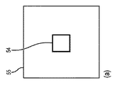
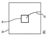
図14(a)−(c)において、デバイスローカライゼーションは、ROI内でデバイスを移動させることによる。システムは、投影画像を表示する画面55上にROIを示す長方形54を提示する。ユーザは、この長方形内にデバイス56を位置付け、X線位置合わせを具体化する際に使用する画像としてその画像を受け入れる。ROI長方形54は、デバイスが見つけられることが期待される場所に提示される(図14(b))。ユーザは、規定された/強調表示されたROI長方形54内にデバイスを位置付け、X線画像を取得する。
In FIGS. 14 (a)-(c), device localization is by moving the device within the ROI. The system presents a
アルゴリズムは、提供されたROI長方形54内の先端57を自動的に検出し、その結果(図14(c)の先端57における画像内のドット)を表示する。
The algorithm automatically detects the
代替として、ユーザは、画像解析アルゴリズムを適用することによって得られた候補結果の組からデバイスポイントを選ぶことができる。各々のTSMボタンタッチは、画像に表示される別の候補結果にフォーカスをタブ付けする(タブナビゲーション)。正しいポイントにフォーカスが合うとき、ユーザは、デバイスポイントとしてこれを設定する。タッチセンシティブ画面において、ユーザは、表示された候補結果の1又は複数の上/周囲を単に触れることによってポイントを示すことができる。 Alternatively, the user can select device points from the set of candidate results obtained by applying the image analysis algorithm. Each TSM button touch tabs the focus to another candidate result displayed in the image (tab navigation). When the correct point is in focus, the user sets this as the device point. On a touch sensitive screen, the user can indicate points by simply touching one or more of the displayed candidate results / periphery.
図15(a)−(c)において、選択は、投影画像(又は画像)70、71、72の自動検出された先端候補から行われる。アルゴリズムは、デバイス先端の複数の候補を検出する。ユーザは、検出閾値を変更し、及び/又は実際の先端に対応する候補ポイントを選択することができる。図15(a)において候補先端ロケーション58'、58''、58'''、58''''、58'''''が、自動的に提示される。ユーザは、検出閾値を増大することによって、図14(b)に示すように検出先端(58'、58''、58''''')の数を低減することができる。ユーザは、検出された先端位置にタブ付けするためにTSMを押す。図14(c)には、星で特徴付けられた選択された実際の先端58'が示される。更に、星で特徴付けられた58'''''が選択されるべき次のものを示す。 In FIGS. 15 (a)-(c), the selection is made from automatically detected tip candidates of the projected images (or images) 70, 71, 72. FIG. The algorithm detects multiple candidates for the device tip. The user can change the detection threshold and / or select candidate points corresponding to the actual tip. In FIG. 15 (a), candidate tip locations 58 ', 58' ', 58' '', 58 '' '', 58 '' '' 'are automatically presented. The user can reduce the number of detection tips (58 ′, 58 ′ ′, 58 ′ ′ ′ ′ ′) as shown in FIG. 14 (b) by increasing the detection threshold. The user presses the TSM to tab to the detected tip position. FIG. 14 (c) shows a selected actual tip 58 'characterized by stars. In addition, the 58 '' '' 'characterized by stars indicates the next one to be selected.
図16(a)、(b)において、デバイスローカライゼーションは、投影画像73、74において規定された解剖学的位置にデバイスを移動させることによる。システムは、例えば図16(a)の59、60、61、62、63のような特定の解剖学的ロケーションにデバイスを位置付けるように、ユーザにリクエストする。リクエストされた位置にデバイスを有するX線画像は、位置合わせに使用する画像として、ユーザによって受け入れられる。ここでリクエストされた位置は60である。デバイスは、要求された位置60にナビゲートされ、その時点ですぐにX線画像が位置合わせのために使用される。
In FIGS. 16 (a), (b), device localization is by moving the device to the anatomical position defined in the projected
更に、システムは、予め規定された解剖学的位置(解剖学的情報は、計画ステップのX線/CT位置合わせ結果からアルゴリズムに対し利用可能でありうる)にROIを設定することができる。デバイス先端が、期待されるロケーションの近くにくると、オペレータは、位置合わせのためにX線画像を取得する。 Additionally, the system can set the ROI to a predefined anatomical location (anatomical information may be available to the algorithm from the X-ray / CT registration results of the planning step). When the device tip is near the expected location, the operator acquires an x-ray image for alignment.
システムは、ユニークなラベルを有する複数ROIを表示することができ(ROIは、規則的なグリッドとして位置付けられることができ、又は画像解析アルゴリズムの関数として位置付けられることができる)、ユーザは、デバイスを示すために1又は複数のROIを選ぶ。ユーザは、1又は複数のROIを選択するために、ボイスコマンド、TSMボタン、タッチスクリーン又はマウスを使用することができる。 The system can display multiple ROIs with unique labels (ROI can be positioned as a regular grid or can be positioned as a function of an image analysis algorithm) and the user can Choose one or more ROIs to show. The user can use voice commands, TSM buttons, a touch screen or a mouse to select one or more ROIs.
図17は、投影画像75上の複数ROIからの選択を示す。システムは、ユーザが選ぶべき例えば65'、65''、65'''のような複数のROIを提供する。ユーザは、ROIの識別子を読み上げることによって、又は、触れる、クリックする又はタブを使用することによって、1又は複数のROIを選択する。ROIは、規則的な格子構造を有することができ、自動的にサイズ設定をされることができ、階層的でありうる。例えば、ROIが選択されると、同じグリッド処理が、より制限された領域を規定するために、選択されたROIに適用されることができる。
FIG. 17 shows the selection from multiple ROIs on the projected
ある例では、先端に加えて、画像内にデバイスのエントリポイントを提供することも望ましいことがある。図18において、スライダ66が、この目的のためにワイヤの入口位置を規定するために使用される。ワイヤ入口の位置を画像に規定するために、スライダ66が、図18に示されるように使用されることができる。ユーザは、入口ポイント77のロケーションにスライダを移動させる。図の下方で、スライダのセグメントは、デバイスの入口領域を規定する。赤いセグメントの幅は、調整されることができる。
In some instances, it may also be desirable to provide a device entry point in the image in addition to the tip. In FIG. 18, a
本発明は、より効率的であると考えられる場合は上述の方法の任意のものを組み合わせることができる。例えば、視野内に複数のデバイスがあってもよく、その場合、ユーザにまずROIを標示させ、次いでアルゴリズム結果から候補を選択することが有用でありうる。 The present invention can be combined with any of the above mentioned methods if it is considered to be more efficient. For example, there may be multiple devices in the field of view, in which case it may be useful to have the user first mark the ROI and then select candidates from the algorithm results.
更に、複数のビューが位置合わせのために使用される場合、1つのビューにおける任意の入力は、他のビューに提示される結果を改善するために使用されることができる。例えば、先端が、ユーザ入力により第1のビューにおいて検出される場合、第2のビューにエピポーラ線が表示されることができ、及び/又はエピポーラ線の周囲のポイント候補のみが、有効なオプションとして提示されることができる。提示される長方形が、それが計算されたエピポーラ線に中心をおかれ、この線に沿ってのみ移動するように、提示されることができる。 Furthermore, if multiple views are used for alignment, any input in one view can be used to improve the results presented in the other view. For example, if the tip is detected in the first view by user input, the epipolar line can be displayed in the second view and / or only the candidate points around the epipolar line are valid options It can be presented. The presented rectangle can be presented such that it is centered on the epipolar line for which it was calculated and moves only along this line.
上述の実施形態において、イメージング装置と追跡装置との位置合わせを規定する位置合わせパラメータを決定するための特定の方法が記述されたが、他の実施形態において、位置合わせユニットは、別のやり方で位置合わせパラメータを決定するように適応されることができる。例えば、ユーザが、マーカを、それぞれ異なる投影方向に対応するいくつかの2次元投影画像に加えたのち、位置合わせユニットは、異なる2次元投影画像に加えられたマーカに基づいて、対象の3次元ロケーションを決定することができ、位置合わせパラメータは、2次元投影画像に加えられたマーカから導き出されたこの3次元ロケーションと、追跡装置によって提供される対象の3次元ロケーションとに基づいて、決定されることができる。 Although in the above embodiments a specific method for determining the alignment parameters defining the alignment of the imaging device and the tracking device has been described, in other embodiments the alignment unit may be otherwise It can be adapted to determine alignment parameters. For example, after the user adds markers to several two-dimensional projection images, each corresponding to a different projection direction, the registration unit is based on the markers added to the different two-dimensional projection images to obtain a three-dimensional object. The location can be determined, and registration parameters are determined based on this three-dimensional location derived from the markers added to the two-dimensional projection image and the three-dimensional location of the object provided by the tracking device. Can be
上述の実施形態において、イメージング装置が、2次元画像を提供するために適応され、対象検出ユニットが、ユーザが、対象が位置する2次元画像内の任意の位置を示すためにマーカを該2次元画像に加えることを可能にするように適応されているが、他の実施形態おいて、イメージング装置は、コンピュータトモグラフィ画像、磁気共鳴画像、X線Cアームシステムによって取得されるさまざまな異なる2次元投影画像から再構成される3次元画像、その他のような、対象の3次元画像を生成するように適応されることもでき、対象検出ユニットは、ユーザがマーカを3次元画像に加えることを可能にし、加えられたマーカに基づいて3次元表現を提供するように適応されることができる。この場合、位置合わせユニットは、イメージング装置の視野内の対象の追跡された3次元ロケーションと、3次元画像における対象の表現の3次元ロケーションとに基づいて、位置合わせパラメータを決定するように適応されることができる。 In the above embodiment, the imaging device is adapted to provide a two-dimensional image, and the object detection unit is configured to display the marker as an indicator to indicate any position in the two-dimensional image at which the object is located. Although adapted to be able to be added to an image, in other embodiments the imaging device may be a computer tomography image, a magnetic resonance image, a variety of different two-dimensional acquired by an X-ray C-arm system It can also be adapted to generate a three-dimensional image of an object, such as a three-dimensional image reconstructed from projection images, etc., and the object detection unit allows the user to add markers to the three-dimensional image , And may be adapted to provide a three-dimensional representation based on the added markers. In this case, the registration unit is adapted to determine registration parameters based on the tracked three-dimensional location of the object in the field of view of the imaging device and the three-dimensional location of the representation of the object in the three-dimensional image. Can be
追跡装置がイメージング装置と位置合わせされたのち、追跡デバイスと位置合わせされたイメージング装置及び他のイメージング装置が、互いに位置合わせされる場合は、対象の追跡されたロケーションは、イメージング装置によって取得されずに他のイメージング装置によって取得された他の画像において表示されることもできる。これらの他の画像は、介入プロシージャの前又は介入プロシージャの間に取得されたものでありうる例えばコンピュータトモグラフィ画像、磁気共鳴画像等でありうる。 If the tracking device is aligned with the imaging device, and the imaging device and the other imaging device aligned with the tracking device are aligned with one another, the tracked location of the object is not obtained by the imaging device Can also be displayed in other images acquired by other imaging devices. These other images may be, for example, computed tomography images, magnetic resonance images, etc. which may have been acquired prior to or during an interventional procedure.
図1を参照して上述された介入システムは、アブレーションプロシージャを実施するように適応されているが、他の実施形態において、介入システムは、別の介入プロシージャを実施するように適応されることができる。更に、位置合わせシステム及び位置合わせ方法が、追跡装置とイメージング装置との位置合わせを必要とする、他の非介入プロシージャにおいても使用されることができる。 While the interventional system described above with reference to FIG. 1 is adapted to perform an ablation procedure, in other embodiments the interventional system may be adapted to perform another interventional procedure it can. In addition, alignment systems and methods may be used in other non-interventional procedures that require alignment of the tracking device with the imaging device.
開示された実施形態に対する他の変更は、図面、開示及び添付の請求項の検討から、請求項に記載の本発明を実施する際に当業者によって理解され達成されることができる。 Other modifications to the disclosed embodiments can be understood and effected by those skilled in the art in practicing the claimed invention, from a study of the drawings, the disclosure and the appended claims.
請求項において、「有する、含む(comprising)」という語は、他の構成要素又はステップを除外せず、不定冠詞「a」又は「an」は複数性を除外しない。 In the claims, the word "comprising" does not exclude other elements or steps, and the indefinite article "a" or "an" does not exclude a plurality.
単一のユニット又は装置が、請求項に列挙されるいくつかのアイテムの機能を果たすことができる。特定の手段が相互に異なる従属請求項に列挙されているという単なる事実は、これらの手段の組み合わせが有利に使用されることができないことを示さない。 A single unit or device can perform the functions of several items recited in the claims. The mere fact that certain measures are recited in mutually different dependent claims does not indicate that a combination of these measures can not be used to advantage.
グラフィカルユーザインタフェースの提供、加えられたマーカに基づく画像内における対象の表現の決定、1又は複数のユニット又は装置によって実施されるプロシージャは、任意の他の数のユニット又は装置によって実施されることができる。位置合わせ方法に従う位置合わせシステムの制御、及び/又はイメージング方法に従うイメージングシステムの制御は、コンピュータプログラムのプログラムコード手段として及び/又は専用ハードウェアとして、実現されることができる。 The provision of the graphical user interface, the determination of the representation of the object in the image based on the added markers, the procedure implemented by one or more units or devices may be performed by any other number of units or devices it can. The control of the alignment system according to the alignment method and / or the control of the imaging system according to the imaging method may be realized as program code means of a computer program and / or as dedicated hardware.
コンピュータプログラムは、他のハードウェアと共に又はその一部として供給される、例えば光学記憶媒体又はソリッドステート媒体のような適切な媒体に記憶され/配布されることができるが、他の形式で、例えばインターネット又は他のワイヤード又はワイヤレス通信システムを通じて配布されることもできる。 The computer program may be stored / distributed on a suitable medium, such as, for example, an optical storage medium or a solid state medium, supplied with or as part of other hardware, but in other forms, for example It may also be distributed through the Internet or other wired or wireless communication systems.
請求項における任意の参照符号は、その範囲を制限するものとして解釈されるべきでない。 Any reference signs in the claims should not be construed as limiting the scope.
本発明は、X線Cアームデバイスのようなイメージング装置を、光学形状センシング追跡装置のような追跡装置と位置合わせする位置合わせシステムに関する。対象検出ユニットは、a)ユーザが、対象上の任意の位置を示すためにマーカを対象の画像に加えることを可能にし、b)加えられたマーカに基づいて対象の表現を提供する、ように適応され、位置合わせユニットは、追跡装置によって追跡される対象のロケーションと表現のロケーションとに基づいて、位置合わせパラメータを決定する。この種の位置合わせは、ユーザにとって可視である画像内の任意の対象について実施されることができ、それにより、位置合わせのために様々な種類の対象を使用することを可能にする。 The present invention relates to an alignment system for aligning an imaging device, such as an x-ray C-arm device, with a tracking device, such as an optical shape sensing tracking device. The object detection unit may: a) allow the user to add markers to the image of the object to indicate any position on the object; b) provide a representation of the object based on the added markers Applied, the registration unit determines registration parameters based on the location of the object to be tracked by the tracking device and the location of the representation. This type of alignment can be performed for any object in the image that is visible to the user, thereby enabling different types of objects to be used for alignment.
Claims (15)
前記画像内の対象を検出する対象検出ユニットであって、a)前記対象が位置する前記画像内の任意の位置を示すために、ユーザがマーカを前記画像に加えることを可能にし、b)前記加えられたマーカを利用して前記画像内における前記対象の表現を算出する、対象検出ユニットと、
前記追跡装置と前記イメージング装置との位置合わせを規定する位置合わせパラメータを決定する位置合わせユニットであって、前記イメージング装置の視野内の対象の追跡されたロケーション及び前記画像内の前記対象の前記表現のロケーションに基づいて、前記位置合わせパラメータを決定する、位置合わせユニットと、
を有する位置合わせシステム。 An alignment system for aligning an imaging device for generating an image of an object and a tracking device for tracking the location of the object within the field of view of the imaging device by determining the position and shape of the object,
An object detection unit for detecting an object in the image, a) allowing a user to add a marker to the image to indicate any position in the image where the object is located, b) the An object detection unit which calculates the representation of the object in the image using the added markers;
A positioning unit for determining the alignment parameters defining the positioning between said tracking device and said imaging device, wherein the representation of the subject of the imaging device in the target tracked location and the image of the field of view A registration unit, which determines the registration parameters based on the location of
Alignment system with.
前記対象検出ユニットは、a)前記2次元投影画像内の前記対象を示すために、ユーザがマーカを前記2次元投影画像に加えることを可能にし、b)前記加えられたマーカを利用して前記2次元投影画像内における前記対象の表現を算出し、
前記位置合わせユニットは、前記イメージング装置の前記視野内の前記対象の追跡されたロケーション及び前記2次元投影画像における前記対象の前記表現のロケーションに基づいて、前記位置合わせパラメータを決定する、請求項1に記載の位置合わせシステム。 The imaging device generates a two-dimensional projection image of the field of view;
The object detection unit, a) in order to show the object in said two-dimensional projection image allows a user to add a marker to the two-dimensional projection images, b) said by using the added markers Calculating a representation of the object in the two-dimensional projection image,
Said alignment unit, on the basis of the said representation location of the object in the target tracked location and the two-dimensional projection images within a field of view of the imaging device to determine the alignment parameters, Claim 1 Alignment system as described in.
前記対象検出ユニットは、a)前記異なる2次元投影画像内の対象を示すために、ユーザがマーカを前記2次元投影画像の各々に加えることを可能にし、b)前記加えられたマーカを利用して前記2次元投影画像内における前記対象の表現を算出し、
前記位置合わせユニットは、前記視野内の対象の追跡されたロケーション及び前記2次元投影画像内の前記対象の前記表現のロケーションに基づいて、前記位置合わせパラメータを決定する、請求項2に記載の位置合わせシステム。 The imaging device generates at least two two-dimensional projection images corresponding to different projection directions,
The object detection unit, a) in order to show the object in the different two-dimensional projection image allows a user to add a marker to each of the two-dimensional projection images, b) by using the added markers calculates said target representation in the two-dimensional projection image Te,
Said alignment unit, on the basis of the location of the representation of the object of interest tracked location and within the two-dimensional projection images within the field of view, to determine the alignment parameters, the position according to claim 2 Tailoring system.
前記位置合わせユニットは、前記2次元投影画像を生成するために前記イメージング装置によって使用される投影ジオメトリを考慮して前記対象の追跡された3次元ロケーションの2次元投影を計算するとともに、前記追跡装置によって規定される座標系と前記イメージング装置によって規定される座標系との間の空間変換を計算することによって、前記位置合わせパラメータを決定し、前記空間変換が、前記対象の前記追跡された3次元ロケーションの計算された2次元投影と、前記2次元投影画像における前記対象の前記表現のロケーションとの間の偏差を最小にする、請求項2に記載の位置合わせシステム。 The tracking device tracks the three-dimensional location of the object;
The alignment unit calculates a two-dimensional projection of the tracked three-dimensional location of the object taking into account the projection geometry used by the imaging device to generate the two-dimensional projection image, and the tracking device Determining the registration parameters by calculating a spatial transformation between a coordinate system defined by and a coordinate system defined by the imaging device, the spatial transformation comprising the three-dimensional traced of the object The alignment system according to claim 2, wherein the deviation between the calculated two-dimensional projection of the location and the location of the representation of the object in the two-dimensional projection image is minimized.
前記位置合わせユニットは、前記光学形状センシングによって追跡される前記イメージング装置の視野内の前記対象のロケーション及び前記画像内の対象の前記表現のロケーションに基づいて、前記位置合わせパラメータを決定する、請求項1に記載の位置合わせシステム。 The tracking device tracks the location of the object by optical shape sensing,
Said alignment unit, on the basis of the location of the representation of the object in the target location and the image within the field of view of said imaging device being tracked by the optical shape sensing, to determine the alignment parameters, Claim Alignment system according to 1.
前記対象検出ユニットは、a)前記2次元投影画像のうち第1の画像内の対象を示すために、ユーザがマーカを前記第1の画像に加えることを可能にし、b)前記加えられたマーカに基づいて前記第1の画像内における前記対象の第1の表現を算出し、前記2次元投影画像のうち第2の画像の画像値に基づいて前記第2の画像内における前記対象の第2の表現を算出し、
前記位置合わせユニットは、前記視野内の前記対象の追跡されたロケーション並びに前記第1及び前記第2の画像内の前記対象の前記第1及び第2の表現のロケーションに基づいて、前記位置合わせパラメータを決定する、請求項1に記載の位置合わせシステム。 The imaging device provides at least two two-dimensional projection images, each corresponding to a different projection direction,
The object detection unit allows a) a user to add a marker to the first image to indicate an object in a first image of the two-dimensional projection image; b) the added marker Calculating a first expression of the object in the first image based on the second image, and calculating a second expression of the object in the second image based on an image value of the second image in the two-dimensional projection image. Calculate the expression of
The alignment unit is configured to adjust the alignment parameter based on the tracked location of the object in the field of view and the locations of the first and second representations of the object in the first and second images. The alignment system of claim 1, wherein:
関心領域の画像を生成するイメージング装置と、
前記対象の位置及び形状を決定することにより前記関心領域内の前記対象のロケーションを追跡する追跡装置と、
位置合わせパラメータを決定する、請求項1に記載の位置合わせシステムと、
前記対象の追跡されたロケーション及び前記決定された位置合わせパラメータに基づいて、前記関心領域の画像内の前記対象のロケーションを決定するロケーション決定ユニットと、
を有する、イメージングシステム。 An imaging system for imaging an object,
An imaging device for generating an image of a region of interest;
A tracking device for tracking the location of the object within the region of interest by determining the location and shape of the object;
The alignment system according to claim 1, wherein the alignment parameters are determined;
A location determination unit for determining the location of the object in the image of the region of interest based on the tracked location of the object and the determined registration parameter;
An imaging system.
対象検出ユニットによって前記画像内の対象を検出するステップであって、前記対象検出ユニットが、a)前記対象が位置する前記画像内の任意の位置を示すために、ユーザがマーカを前記画像に加えることを可能にし、b)前記加えられたマーカを利用して、前記画像内における前記対象の表現を算出する、ことを含むステップと、
位置合わせユニットによって前記イメージング装置と前記追跡装置の位置合わせを規定する位置合わせパラメータを決定するステップであって、前記位置合わせユニットが、前記イメージング装置の視野内の前記対象の追跡されたロケーション及び前記画像内の前記対象の前記表現のロケーションに基づいて、前記位置合わせパラメータを決定する、ことを含むステップと、
を含む位置合わせ方法。 A registration method for aligning an imaging device for generating an image of an object and a tracking device for tracking the location of the object within the field of view of the imaging device by determining the position and shape of the object,
Detecting an object in the image by an object detection unit, wherein the object detection unit adds a marker to the image to indicate a) any position in the image where the object is located B) calculating b) a representation of the object in the image using b) the added marker;
Determining, by means of an alignment unit, alignment parameters which define the alignment of the imaging device and the tracking device, wherein the alignment unit comprises: tracking the tracked location of the object within the field of view of the imaging device; based on the location of said representation of the target in the image, it determines the alignment parameters, and a step that includes,
Alignment method including:
イメージング装置が、関心領域の画像を生成するステップと、
追跡装置が、前記対象の位置及び形状を決定することにより前記関心領域内の対象のロケーションを追跡するステップと、
位置合わせシステムが、請求項12に記載の位置合わせ方法によって、位置合わせパラメータを決定するステップと、
ロケーション画像生成ユニットが、前記対象の追跡されたロケーション、前記関心領域の画像、及び前記決定された位置合わせパラメータに基づいて、前記関心領域の画像内の前記対象のロケーションを示すロケーション画像を生成するステップと、
を含む、イメージングシステムの作動方法。 A method of operating an imaging system for imaging an object, comprising:
Imaging device, and generating an image of the region of interest,
A step of tracking device tracks the target location of the ROI by determining the position and shape of the object,
An alignment system determining alignment parameters according to the alignment method according to claim 12;
Location image generation unit is tracked location of the object, the image of the region of interest, and based on the determined alignment parameter, and generates a location image showing said object location within the image of the region of interest Step and
A method of operating an imaging system , including:
Applications Claiming Priority (3)
| Application Number | Priority Date | Filing Date | Title |
|---|---|---|---|
| EP13177524 | 2013-07-23 | ||
| EP13177524.9 | 2013-07-23 | ||
| PCT/EP2014/063904 WO2015010859A1 (en) | 2013-07-23 | 2014-07-01 | Registration system for registering an imaging device with a tracking device |
Publications (3)
| Publication Number | Publication Date |
|---|---|
| JP2016525000A JP2016525000A (en) | 2016-08-22 |
| JP2016525000A5 JP2016525000A5 (en) | 2017-08-03 |
| JP6511050B2 true JP6511050B2 (en) | 2019-05-08 |
Family
ID=48856518
Family Applications (1)
| Application Number | Title | Priority Date | Filing Date |
|---|---|---|---|
| JP2016528387A Active JP6511050B2 (en) | 2013-07-23 | 2014-07-01 | Alignment system for aligning an imaging device with a tracking device, imaging system, intervention system, alignment method, operation method of imaging system, alignment computer program, and imaging computer program |
Country Status (5)
| Country | Link |
|---|---|
| US (1) | US10762380B2 (en) |
| EP (1) | EP3025304B1 (en) |
| JP (1) | JP6511050B2 (en) |
| CN (1) | CN105408939B (en) |
| WO (1) | WO2015010859A1 (en) |
Families Citing this family (21)
| Publication number | Priority date | Publication date | Assignee | Title |
|---|---|---|---|---|
| US10105117B2 (en) * | 2015-02-13 | 2018-10-23 | Biosense Webster (Israel) Ltd. | Compensation for heart movement using coronary sinus catheter images |
| WO2017102530A1 (en) * | 2015-12-18 | 2017-06-22 | Koninklijke Philips N.V. | Image processing for improved marker positioning on a line-shaped image feature |
| JP6828047B2 (en) | 2016-02-12 | 2021-02-10 | インテュイティブ サージカル オペレーションズ, インコーポレイテッド | Posture estimation and calibration system and method for fluoroscopic imaging system in image-guided surgery |
| WO2018002109A1 (en) | 2016-06-30 | 2018-01-04 | Koninklijke Philips N.V. | Medical navigation system employing optical position sensing and method of operation thereof |
| DE102016117889B3 (en) * | 2016-09-22 | 2018-03-15 | Tomtec Imaging Systems Gmbh | Method and device for correcting dynamic models determined by tracking methods |
| JP7249278B2 (en) * | 2016-12-15 | 2023-03-30 | アルコン インコーポレイティド | Adaptive image registration for ophthalmic surgery |
| CN108245244B (en) * | 2016-12-28 | 2019-12-13 | 中国科学院深圳先进技术研究院 | Radio frequency ablation method and device |
| EP3565498A4 (en) * | 2017-01-09 | 2020-09-30 | Intuitive Surgical Operations Inc. | Systems and methods for registering elongate devices to three dimensional images in image-guided procedures |
| WO2018137759A1 (en) * | 2017-01-24 | 2018-08-02 | Brainlab Ag | Determining rotational orientation of a deep brain stimulation electrode in a three-dimensional image |
| US10430641B2 (en) * | 2017-03-08 | 2019-10-01 | GM Global Technology Operations LLC | Methods and systems for object tracking using bounding boxes |
| EP3385747B1 (en) * | 2017-04-05 | 2021-03-31 | Axis AB | Method, device and system for mapping position detections to a graphical representation |
| US20170209225A1 (en) * | 2017-04-10 | 2017-07-27 | Danling Wu | Stereotactic medical procedure using sequential references and system thereof |
| CN107123110A (en) * | 2017-04-13 | 2017-09-01 | 青岛海信医疗设备股份有限公司 | Wall of the chest line detecting method and device |
| CN107392843B (en) * | 2017-07-21 | 2021-05-07 | 上海联影医疗科技股份有限公司 | Image processing method, device and system |
| EP3542747A1 (en) | 2018-03-22 | 2019-09-25 | Koninklijke Philips N.V. | Visualization system for visualizing an alignment accuracy |
| JP7078487B2 (en) * | 2018-08-02 | 2022-05-31 | 富士フイルムヘルスケア株式会社 | Ultrasound diagnostic equipment and ultrasonic image processing method |
| EP3682836A1 (en) * | 2019-01-21 | 2020-07-22 | Koninklijke Philips N.V. | Assisting in moving an insertion element within an object |
| CN112204615B (en) * | 2019-01-31 | 2023-05-02 | 深圳华大生命科学研究院 | Fluorescence image registration method, gene sequencer, system and storage medium |
| WO2020206421A1 (en) * | 2019-04-04 | 2020-10-08 | Centerline Biomedical, Inc. | Spatial registration of tracking system with an image using two-dimensional image projections |
| CN111784751B (en) * | 2020-06-16 | 2022-12-02 | 北京理工大学 | 3D/2D registration-based guide wire 3D simulation tracking method and device |
| EP3944809A1 (en) * | 2020-07-28 | 2022-02-02 | Koninklijke Philips N.V. | Arrangement and method for determining the position of an invasive device |
Family Cites Families (42)
| Publication number | Priority date | Publication date | Assignee | Title |
|---|---|---|---|---|
| US7747312B2 (en) * | 2000-01-04 | 2010-06-29 | George Mason Intellectual Properties, Inc. | System and method for automatic shape registration and instrument tracking |
| US6950532B1 (en) * | 2000-04-24 | 2005-09-27 | Cinea Inc. | Visual copyright protection |
| US7043019B2 (en) * | 2001-02-28 | 2006-05-09 | Eastman Kodak Company | Copy protection for digital motion picture image data |
| US7221759B2 (en) * | 2003-03-27 | 2007-05-22 | Eastman Kodak Company | Projector with enhanced security camcorder defeat |
| US7006630B2 (en) * | 2003-06-03 | 2006-02-28 | Matsushita Electric Industrial Co., Ltd. | Methods and apparatus for digital content protection |
| DE10325003A1 (en) * | 2003-06-03 | 2004-12-30 | Siemens Ag | Visualization of 2D / 3D-merged image data for catheter angiography |
| US7772541B2 (en) | 2004-07-16 | 2010-08-10 | Luna Innnovations Incorporated | Fiber optic position and/or shape sensing based on rayleigh scatter |
| US7781724B2 (en) * | 2004-07-16 | 2010-08-24 | Luna Innovations Incorporated | Fiber optic position and shape sensing device and method relating thereto |
| CA2588002A1 (en) * | 2005-01-18 | 2006-07-27 | Traxtal Inc. | Method and apparatus for guiding an instrument to a target in the lung |
| US7713205B2 (en) * | 2005-06-29 | 2010-05-11 | Accuray Incorporated | Dynamic tracking of soft tissue targets with ultrasound images, without using fiducial markers |
| WO2007135609A2 (en) * | 2006-05-24 | 2007-11-29 | Koninklijke Philips Electronics, N.V. | Coordinate system registration |
| US8050482B2 (en) * | 2006-09-28 | 2011-11-01 | Siemens Medical Solutions Usa, Inc. | System and method for online optimization of guidewire visibility in fluoroscopic systems |
| US8098914B2 (en) * | 2007-03-05 | 2012-01-17 | Siemens Aktiengesellschaft | Registration of CT volumes with fluoroscopic images |
| US8150494B2 (en) * | 2007-03-29 | 2012-04-03 | Medtronic Navigation, Inc. | Apparatus for registering a physical space to image space |
| US8224432B2 (en) * | 2007-05-08 | 2012-07-17 | C.R.Bard, Inc. | Rapid 3D mapping using multielectrode position data |
| IL184151A0 (en) * | 2007-06-21 | 2007-10-31 | Diagnostica Imaging Software Ltd | X-ray measurement method |
| EP2626027B1 (en) * | 2007-08-14 | 2020-04-29 | Koninklijke Philips N.V. | Robotic instrument systems utilizing optical fiber sensors |
| US8423121B2 (en) * | 2008-08-11 | 2013-04-16 | Siemens Aktiengesellschaft | Method and system for guidewire tracking in fluoroscopic image sequences |
| US20100056904A1 (en) * | 2008-09-02 | 2010-03-04 | Saunders John K | Image guided intervention |
| JP2010115429A (en) * | 2008-11-14 | 2010-05-27 | Toshiba Corp | X-ray diagnostic apparatus and image processing apparatus |
| JP5641707B2 (en) | 2009-04-08 | 2014-12-17 | 株式会社東芝 | X-ray diagnostic equipment |
| US8737708B2 (en) * | 2009-05-13 | 2014-05-27 | Medtronic Navigation, Inc. | System and method for automatic registration between an image and a subject |
| US8731642B2 (en) * | 2009-11-08 | 2014-05-20 | Paieon Inc. | Apparatus and method for locating a device tip within a volume |
| US8526691B2 (en) * | 2010-06-09 | 2013-09-03 | Siemens Aktiengesellschaft | System and method for passive medical device navigation under real-time MRI guidance |
| US20120150025A1 (en) | 2010-09-21 | 2012-06-14 | Siemens Corporation | Image Registration Using Interventional Devices |
| JP5194138B2 (en) * | 2011-03-02 | 2013-05-08 | 富士フイルム株式会社 | Image diagnosis support apparatus, operation method thereof, and image diagnosis support program |
| US8666477B2 (en) * | 2011-03-07 | 2014-03-04 | Siemens Aktiengesellschaft | Method and system for tracking of a virtual electrode on a coronary sinus catheter in fluoroscopic images |
| WO2012143885A2 (en) | 2011-04-21 | 2012-10-26 | Koninklijke Philips Electronics N.V. | Mpr slice selection for visualization of catheter in three-dimensional ultrasound |
| CN103648394B (en) * | 2011-06-27 | 2016-11-16 | 皇家飞利浦有限公司 | Use the real-time 3D angiography of surgical technique and tools curve and the registration of X-ray image |
| WO2013024418A1 (en) * | 2011-08-16 | 2013-02-21 | Koninklijke Philips Electronics N.V. | Curved multi-planar reconstruction using fiber optic shape data |
| US9220467B2 (en) * | 2011-09-19 | 2015-12-29 | Siemens Aktiengesellschaft | Method and system for tracking catheters in 2D X-ray fluoroscopy using a graphics processing unit |
| WO2013057620A1 (en) * | 2011-10-20 | 2013-04-25 | Koninklijke Philips Electronics N.V. | Shape sensing assisted medical procedure |
| WO2013071437A1 (en) * | 2011-11-15 | 2013-05-23 | Macdonald Dettwiler & Associates Inc. | Method of real-time tracking of moving/flexible surfaces |
| RU2014143669A (en) * | 2012-03-29 | 2016-05-27 | Конинклейке Филипс Н.В. | TROUBLESHOOTING USING FORM READING |
| EP2836959A2 (en) * | 2012-04-13 | 2015-02-18 | Lightcraft Technology, LLC | Hybrid precision tracking |
| EP2846688A4 (en) * | 2012-05-08 | 2015-09-23 | Angiometrix Corp | Systems for linear mapping of lumens |
| US9014564B2 (en) * | 2012-09-24 | 2015-04-21 | Intel Corporation | Light receiver position determination |
| RU2638445C2 (en) * | 2012-10-01 | 2017-12-13 | Конинклейке Филипс Н.В. | Three-dimensional polylinear combination with use of limitations of form |
| US9341014B2 (en) * | 2012-12-27 | 2016-05-17 | Panasonic Intellectual Property Corporation Of America | Information communication method using change in luminance |
| US9608727B2 (en) * | 2012-12-27 | 2017-03-28 | Panasonic Intellectual Property Corporation Of America | Switched pixel visible light transmitting method, apparatus and program |
| US9460510B2 (en) * | 2013-03-29 | 2016-10-04 | Siemens Medical Solutions Usa, Inc. | Synchronized navigation of medical images |
| US10307079B2 (en) * | 2014-01-27 | 2019-06-04 | Edda Technology, Inc. | Method and system for surgical instrument guidance and tracking with position and orientation correction |
-
2014
- 2014-07-01 WO PCT/EP2014/063904 patent/WO2015010859A1/en active Application Filing
- 2014-07-01 CN CN201480041547.4A patent/CN105408939B/en active Active
- 2014-07-01 JP JP2016528387A patent/JP6511050B2/en active Active
- 2014-07-01 EP EP14734148.1A patent/EP3025304B1/en active Active
- 2014-07-01 US US14/906,289 patent/US10762380B2/en active Active
Also Published As
| Publication number | Publication date |
|---|---|
| JP2016525000A (en) | 2016-08-22 |
| WO2015010859A1 (en) | 2015-01-29 |
| CN105408939B (en) | 2021-08-24 |
| US10762380B2 (en) | 2020-09-01 |
| EP3025304B1 (en) | 2021-09-08 |
| US20160171714A1 (en) | 2016-06-16 |
| CN105408939A (en) | 2016-03-16 |
| EP3025304A1 (en) | 2016-06-01 |
Similar Documents
| Publication | Publication Date | Title |
|---|---|---|
| JP6511050B2 (en) | Alignment system for aligning an imaging device with a tracking device, imaging system, intervention system, alignment method, operation method of imaging system, alignment computer program, and imaging computer program | |
| JP7093801B2 (en) | A system that facilitates position adjustment and guidance during surgery | |
| US20220133412A1 (en) | Apparatus and methods for use with image-guided skeletal procedures | |
| JP7322039B2 (en) | Imaging Device Pose Estimation and Systems and Methods for Determining the Position of a Medical Device Relative to a Target | |
| US10181074B2 (en) | Positioning of an examination table relative to a medical imaging apparatus | |
| JP7284736B2 (en) | Apparatus for determining the position of an interventional instrument in a projected image | |
| AU2015238800B2 (en) | Real-time simulation of fluoroscopic images | |
| CN102598088A (en) | Systems & methods for planning and performing percutaneous needle procedures | |
| EP3079622B1 (en) | Radiation-free registration of an optical shape sensing system to an imaging system | |
| US10588702B2 (en) | System and methods for updating patient registration during surface trace acquisition | |
| US20220110698A1 (en) | Apparatus and methods for use with image-guided skeletal procedures | |
| EP3063734A1 (en) | Assisting apparatus for assisting in registering an imaging device with a position and shape determination device | |
| CN113855239A (en) | Guide wire navigation system and method in vascular interventional operation | |
| AU2015213326A1 (en) | Marking of fluoroscope field-of-view | |
| JP2018043000A (en) | Ent image registration | |
| CN114746901A (en) | Registration of images with tracking systems |
Legal Events
| Date | Code | Title | Description |
|---|---|---|---|
| RD04 | Notification of resignation of power of attorney |
Free format text: JAPANESE INTERMEDIATE CODE: A7424 Effective date: 20170214 |
|
| A521 | Request for written amendment filed |
Free format text: JAPANESE INTERMEDIATE CODE: A523 Effective date: 20170623 |
|
| A621 | Written request for application examination |
Free format text: JAPANESE INTERMEDIATE CODE: A621 Effective date: 20170623 |
|
| A977 | Report on retrieval |
Free format text: JAPANESE INTERMEDIATE CODE: A971007 Effective date: 20180228 |
|
| A131 | Notification of reasons for refusal |
Free format text: JAPANESE INTERMEDIATE CODE: A131 Effective date: 20180403 |
|
| A601 | Written request for extension of time |
Free format text: JAPANESE INTERMEDIATE CODE: A601 Effective date: 20180702 |
|
| A521 | Request for written amendment filed |
Free format text: JAPANESE INTERMEDIATE CODE: A523 Effective date: 20181003 |
|
| TRDD | Decision of grant or rejection written | ||
| A01 | Written decision to grant a patent or to grant a registration (utility model) |
Free format text: JAPANESE INTERMEDIATE CODE: A01 Effective date: 20190402 |
|
| A61 | First payment of annual fees (during grant procedure) |
Free format text: JAPANESE INTERMEDIATE CODE: A61 Effective date: 20190405 |
|
| R150 | Certificate of patent or registration of utility model |
Ref document number: 6511050 Country of ref document: JP Free format text: JAPANESE INTERMEDIATE CODE: R150 |
|
| R250 | Receipt of annual fees |
Free format text: JAPANESE INTERMEDIATE CODE: R250 |
|
| R250 | Receipt of annual fees |
Free format text: JAPANESE INTERMEDIATE CODE: R250 |
|
| R250 | Receipt of annual fees |
Free format text: JAPANESE INTERMEDIATE CODE: R250 |