JP6510495B2 - Supplemental device for attachment to an injection device - Google Patents
Supplemental device for attachment to an injection device Download PDFInfo
- Publication number
- JP6510495B2 JP6510495B2 JP2016512303A JP2016512303A JP6510495B2 JP 6510495 B2 JP6510495 B2 JP 6510495B2 JP 2016512303 A JP2016512303 A JP 2016512303A JP 2016512303 A JP2016512303 A JP 2016512303A JP 6510495 B2 JP6510495 B2 JP 6510495B2
- Authority
- JP
- Japan
- Prior art keywords
- dose
- injection device
- supplemental
- injection
- state
- Prior art date
- Legal status (The legal status is an assumption and is not a legal conclusion. Google has not performed a legal analysis and makes no representation as to the accuracy of the status listed.)
- Active
Links
- 239000007924 injection Substances 0.000 title claims description 212
- 238000002347 injection Methods 0.000 title claims description 212
- 230000000153 supplemental effect Effects 0.000 title claims description 187
- 239000003814 drug Substances 0.000 claims description 42
- 229940079593 drug Drugs 0.000 claims description 40
- 230000008859 change Effects 0.000 claims description 27
- 238000012015 optical character recognition Methods 0.000 claims description 26
- 230000005611 electricity Effects 0.000 claims 1
- NOESYZHRGYRDHS-UHFFFAOYSA-N insulin Chemical compound N1C(=O)C(NC(=O)C(CCC(N)=O)NC(=O)C(CCC(O)=O)NC(=O)C(C(C)C)NC(=O)C(NC(=O)CN)C(C)CC)CSSCC(C(NC(CO)C(=O)NC(CC(C)C)C(=O)NC(CC=2C=CC(O)=CC=2)C(=O)NC(CCC(N)=O)C(=O)NC(CC(C)C)C(=O)NC(CCC(O)=O)C(=O)NC(CC(N)=O)C(=O)NC(CC=2C=CC(O)=CC=2)C(=O)NC(CSSCC(NC(=O)C(C(C)C)NC(=O)C(CC(C)C)NC(=O)C(CC=2C=CC(O)=CC=2)NC(=O)C(CC(C)C)NC(=O)C(C)NC(=O)C(CCC(O)=O)NC(=O)C(C(C)C)NC(=O)C(CC(C)C)NC(=O)C(CC=2NC=NC=2)NC(=O)C(CO)NC(=O)CNC2=O)C(=O)NCC(=O)NC(CCC(O)=O)C(=O)NC(CCCNC(N)=N)C(=O)NCC(=O)NC(CC=3C=CC=CC=3)C(=O)NC(CC=3C=CC=CC=3)C(=O)NC(CC=3C=CC(O)=CC=3)C(=O)NC(C(C)O)C(=O)N3C(CCC3)C(=O)NC(CCCCN)C(=O)NC(C)C(O)=O)C(=O)NC(CC(N)=O)C(O)=O)=O)NC(=O)C(C(C)CC)NC(=O)C(CO)NC(=O)C(C(C)O)NC(=O)C1CSSCC2NC(=O)C(CC(C)C)NC(=O)C(NC(=O)C(CCC(N)=O)NC(=O)C(CC(N)=O)NC(=O)C(NC(=O)C(N)CC=1C=CC=CC=1)C(C)C)CC1=CN=CN1 NOESYZHRGYRDHS-UHFFFAOYSA-N 0.000 description 68
- 230000007704 transition Effects 0.000 description 37
- 102000004877 Insulin Human genes 0.000 description 35
- 108090001061 Insulin Proteins 0.000 description 35
- 239000008280 blood Substances 0.000 description 34
- 210000004369 blood Anatomy 0.000 description 34
- 229940125396 insulin Drugs 0.000 description 34
- WQZGKKKJIJFFOK-GASJEMHNSA-N Glucose Natural products OC[C@H]1OC(O)[C@H](O)[C@@H](O)[C@@H]1O WQZGKKKJIJFFOK-GASJEMHNSA-N 0.000 description 31
- 239000008103 glucose Substances 0.000 description 31
- 238000004891 communication Methods 0.000 description 26
- 238000012544 monitoring process Methods 0.000 description 23
- 238000001514 detection method Methods 0.000 description 16
- 238000010586 diagram Methods 0.000 description 16
- 230000005540 biological transmission Effects 0.000 description 15
- 238000000034 method Methods 0.000 description 15
- 101000579646 Penaeus vannamei Penaeidin-1 Proteins 0.000 description 8
- 238000012790 confirmation Methods 0.000 description 8
- 230000006870 function Effects 0.000 description 8
- 230000004044 response Effects 0.000 description 8
- 230000009471 action Effects 0.000 description 7
- 230000000295 complement effect Effects 0.000 description 6
- 229940112930 apidra Drugs 0.000 description 5
- RCHHVVGSTHAVPF-ZPHPLDECSA-N apidra Chemical compound C([C@@H](C(=O)N[C@@H](CC(C)C)C(=O)N[C@H]1CSSC[C@H]2C(=O)N[C@H](C(=O)N[C@@H](CO)C(=O)N[C@H](C(=O)N[C@H](C(N[C@@H](CO)C(=O)N[C@@H](CC(C)C)C(=O)N[C@@H](CC=3C=CC(O)=CC=3)C(=O)N[C@@H](CCC(N)=O)C(=O)N[C@@H](CC(C)C)C(=O)N[C@@H](CCC(O)=O)C(=O)N[C@@H](CC(N)=O)C(=O)N[C@@H](CC=3C=CC(O)=CC=3)C(=O)N[C@@H](CSSC[C@H](NC(=O)[C@H](C(C)C)NC(=O)[C@H](CC(C)C)NC(=O)[C@H](CC=3C=CC(O)=CC=3)NC(=O)[C@H](CC(C)C)NC(=O)[C@H](C)NC(=O)[C@H](CCC(O)=O)NC(=O)[C@H](C(C)C)NC(=O)[C@H](CC(C)C)NC(=O)[C@H](CC=3N=CNC=3)NC(=O)[C@H](CO)NC(=O)CNC1=O)C(=O)NCC(=O)N[C@@H](CCC(O)=O)C(=O)N[C@@H](CCCNC(N)=N)C(=O)NCC(=O)N[C@@H](CC=1C=CC=CC=1)C(=O)N[C@@H](CC=1C=CC=CC=1)C(=O)N[C@@H](CC=1C=CC(O)=CC=1)C(=O)N[C@@H]([C@@H](C)O)C(=O)N1[C@@H](CCC1)C(=O)N[C@@H](CCC(O)=O)C(=O)N[C@@H]([C@@H](C)O)C(O)=O)C(=O)N[C@@H](CC(N)=O)C(O)=O)=O)CSSC[C@@H](C(N2)=O)NC(=O)[C@H](CCC(N)=O)NC(=O)[C@H](CCC(O)=O)NC(=O)[C@H](C(C)C)NC(=O)[C@@H](NC(=O)CN)[C@@H](C)CC)[C@@H](C)CC)[C@@H](C)O)NC(=O)[C@H](CCC(N)=O)NC(=O)[C@H](CCCCN)NC(=O)[C@@H](NC(=O)[C@@H](N)CC=1C=CC=CC=1)C(C)C)C1=CNC=N1 RCHHVVGSTHAVPF-ZPHPLDECSA-N 0.000 description 5
- 239000003795 chemical substances by application Substances 0.000 description 5
- 108700039926 insulin glulisine Proteins 0.000 description 5
- 238000003825 pressing Methods 0.000 description 5
- 230000008569 process Effects 0.000 description 5
- 238000003860 storage Methods 0.000 description 5
- 230000008901 benefit Effects 0.000 description 4
- 229940127560 insulin pen Drugs 0.000 description 4
- 230000003287 optical effect Effects 0.000 description 4
- 230000008878 coupling Effects 0.000 description 3
- 238000010168 coupling process Methods 0.000 description 3
- 238000005859 coupling reaction Methods 0.000 description 3
- 230000013011 mating Effects 0.000 description 3
- 238000012545 processing Methods 0.000 description 3
- 230000007958 sleep Effects 0.000 description 3
- 108010057186 Insulin Glargine Proteins 0.000 description 2
- COCFEDIXXNGUNL-RFKWWTKHSA-N Insulin glargine Chemical compound C([C@@H](C(=O)N[C@@H](CC(C)C)C(=O)N[C@H]1CSSC[C@H]2C(=O)N[C@H](C(=O)N[C@@H](CO)C(=O)N[C@H](C(=O)N[C@H](C(N[C@@H](CO)C(=O)N[C@@H](CC(C)C)C(=O)N[C@@H](CC=3C=CC(O)=CC=3)C(=O)N[C@@H](CCC(N)=O)C(=O)N[C@@H](CC(C)C)C(=O)N[C@@H](CCC(O)=O)C(=O)N[C@@H](CC(N)=O)C(=O)N[C@@H](CC=3C=CC(O)=CC=3)C(=O)N[C@@H](CSSC[C@H](NC(=O)[C@H](C(C)C)NC(=O)[C@H](CC(C)C)NC(=O)[C@H](CC=3C=CC(O)=CC=3)NC(=O)[C@H](CC(C)C)NC(=O)[C@H](C)NC(=O)[C@H](CCC(O)=O)NC(=O)[C@H](C(C)C)NC(=O)[C@H](CC(C)C)NC(=O)[C@H](CC=3NC=NC=3)NC(=O)[C@H](CO)NC(=O)CNC1=O)C(=O)NCC(=O)N[C@@H](CCC(O)=O)C(=O)N[C@@H](CCCNC(N)=N)C(=O)NCC(=O)N[C@@H](CC=1C=CC=CC=1)C(=O)N[C@@H](CC=1C=CC=CC=1)C(=O)N[C@@H](CC=1C=CC(O)=CC=1)C(=O)N[C@@H]([C@@H](C)O)C(=O)N1[C@@H](CCC1)C(=O)N[C@@H](CCCCN)C(=O)N[C@@H]([C@@H](C)O)C(=O)N[C@@H](CCCNC(N)=N)C(=O)N[C@@H](CCCNC(N)=N)C(O)=O)C(=O)NCC(O)=O)=O)CSSC[C@@H](C(N2)=O)NC(=O)[C@H](CCC(N)=O)NC(=O)[C@H](CCC(O)=O)NC(=O)[C@H](C(C)C)NC(=O)[C@@H](NC(=O)CN)[C@@H](C)CC)[C@@H](C)CC)[C@@H](C)O)NC(=O)[C@H](CCC(N)=O)NC(=O)[C@H](CC(N)=O)NC(=O)[C@@H](NC(=O)[C@@H](N)CC=1C=CC=CC=1)C(C)C)C1=CN=CN1 COCFEDIXXNGUNL-RFKWWTKHSA-N 0.000 description 2
- 238000004364 calculation method Methods 0.000 description 2
- 238000004590 computer program Methods 0.000 description 2
- 230000003247 decreasing effect Effects 0.000 description 2
- 238000009826 distribution Methods 0.000 description 2
- 230000005059 dormancy Effects 0.000 description 2
- 229940060975 lantus Drugs 0.000 description 2
- 239000007788 liquid Substances 0.000 description 2
- 238000004519 manufacturing process Methods 0.000 description 2
- 230000009467 reduction Effects 0.000 description 2
- 239000000523 sample Substances 0.000 description 2
- 230000001960 triggered effect Effects 0.000 description 2
- HTTJABKRGRZYRN-UHFFFAOYSA-N Heparin Chemical compound OC1C(NC(=O)C)C(O)OC(COS(O)(=O)=O)C1OC1C(OS(O)(=O)=O)C(O)C(OC2C(C(OS(O)(=O)=O)C(OC3C(C(O)C(O)C(O3)C(O)=O)OS(O)(=O)=O)C(CO)O2)NS(O)(=O)=O)C(C(O)=O)O1 HTTJABKRGRZYRN-UHFFFAOYSA-N 0.000 description 1
- 125000002066 L-histidyl group Chemical group [H]N1C([H])=NC(C([H])([H])[C@](C(=O)[*])([H])N([H])[H])=C1[H] 0.000 description 1
- 206010067584 Type 1 diabetes mellitus Diseases 0.000 description 1
- 230000004913 activation Effects 0.000 description 1
- 238000013459 approach Methods 0.000 description 1
- 230000009286 beneficial effect Effects 0.000 description 1
- 239000012876 carrier material Substances 0.000 description 1
- POIUWJQBRNEFGX-XAMSXPGMSA-N cathelicidin Chemical compound C([C@@H](C(=O)N[C@@H](CCCNC(N)=N)C(=O)N[C@@H](CCCCN)C(=O)N[C@@H](CO)C(=O)N[C@@H](CCCCN)C(=O)N[C@@H](CCC(O)=O)C(=O)N[C@@H](CCCCN)C(=O)N[C@@H]([C@@H](C)CC)C(=O)NCC(=O)N[C@@H](CCCCN)C(=O)N[C@@H](CCC(O)=O)C(=O)N[C@@H](CC=1C=CC=CC=1)C(=O)N[C@@H](CCCCN)C(=O)N[C@@H](CCCNC(N)=N)C(=O)N[C@@H]([C@@H](C)CC)C(=O)N[C@@H](C(C)C)C(=O)N[C@@H](CCC(N)=O)C(=O)N[C@@H](CCCNC(N)=N)C(=O)N[C@@H]([C@@H](C)CC)C(=O)N[C@@H](CCCCN)C(=O)N[C@@H](CC(O)=O)C(=O)N[C@@H](CC=1C=CC=CC=1)C(=O)N[C@@H](CC(C)C)C(=O)N[C@@H](CCCNC(N)=N)C(=O)N[C@@H](CC(N)=O)C(=O)N[C@@H](CC(C)C)C(=O)N[C@@H](C(C)C)C(=O)N1[C@@H](CCC1)C(=O)N[C@@H](CCCNC(N)=N)C(=O)N[C@@H]([C@@H](C)O)C(=O)N[C@@H](CCC(O)=O)C(=O)N[C@@H](CO)C(O)=O)NC(=O)[C@H](CC=1C=CC=CC=1)NC(=O)[C@H](CC(O)=O)NC(=O)CNC(=O)[C@H](CC(C)C)NC(=O)[C@@H](N)CC(C)C)C1=CC=CC=C1 POIUWJQBRNEFGX-XAMSXPGMSA-N 0.000 description 1
- 238000012937 correction Methods 0.000 description 1
- 230000007423 decrease Effects 0.000 description 1
- 238000013461 design Methods 0.000 description 1
- 206010012601 diabetes mellitus Diseases 0.000 description 1
- 201000010099 disease Diseases 0.000 description 1
- 208000037265 diseases, disorders, signs and symptoms Diseases 0.000 description 1
- 238000011156 evaluation Methods 0.000 description 1
- 239000000835 fiber Substances 0.000 description 1
- 229960002897 heparin Drugs 0.000 description 1
- 229920000669 heparin Polymers 0.000 description 1
- 238000005286 illumination Methods 0.000 description 1
- 238000010191 image analysis Methods 0.000 description 1
- 230000001771 impaired effect Effects 0.000 description 1
- 238000001727 in vivo Methods 0.000 description 1
- 230000000977 initiatory effect Effects 0.000 description 1
- 238000007689 inspection Methods 0.000 description 1
- 239000004026 insulin derivative Substances 0.000 description 1
- 239000004973 liquid crystal related substance Substances 0.000 description 1
- 239000000463 material Substances 0.000 description 1
- 238000005259 measurement Methods 0.000 description 1
- 230000004048 modification Effects 0.000 description 1
- 238000012986 modification Methods 0.000 description 1
- 238000010606 normalization Methods 0.000 description 1
- 238000003909 pattern recognition Methods 0.000 description 1
- 229920003229 poly(methyl methacrylate) Polymers 0.000 description 1
- 239000004926 polymethyl methacrylate Substances 0.000 description 1
- 230000011218 segmentation Effects 0.000 description 1
- 230000005236 sound signal Effects 0.000 description 1
- 238000001228 spectrum Methods 0.000 description 1
- 239000012899 standard injection Substances 0.000 description 1
- 238000004448 titration Methods 0.000 description 1
- 208000001072 type 2 diabetes mellitus Diseases 0.000 description 1
Images


Classifications
-
- A—HUMAN NECESSITIES
- A61—MEDICAL OR VETERINARY SCIENCE; HYGIENE
- A61M—DEVICES FOR INTRODUCING MEDIA INTO, OR ONTO, THE BODY; DEVICES FOR TRANSDUCING BODY MEDIA OR FOR TAKING MEDIA FROM THE BODY; DEVICES FOR PRODUCING OR ENDING SLEEP OR STUPOR
- A61M5/00—Devices for bringing media into the body in a subcutaneous, intra-vascular or intramuscular way; Accessories therefor, e.g. filling or cleaning devices, arm-rests
- A61M5/178—Syringes
- A61M5/31—Details
- A61M5/315—Pistons; Piston-rods; Guiding, blocking or restricting the movement of the rod or piston; Appliances on the rod for facilitating dosing ; Dosing mechanisms
- A61M5/31533—Dosing mechanisms, i.e. setting a dose
- A61M5/31545—Setting modes for dosing
- A61M5/31548—Mechanically operated dose setting member
- A61M5/3155—Mechanically operated dose setting member by rotational movement of dose setting member, e.g. during setting or filling of a syringe
-
- G—PHYSICS
- G01—MEASURING; TESTING
- G01D—MEASURING NOT SPECIALLY ADAPTED FOR A SPECIFIC VARIABLE; ARRANGEMENTS FOR MEASURING TWO OR MORE VARIABLES NOT COVERED IN A SINGLE OTHER SUBCLASS; TARIFF METERING APPARATUS; MEASURING OR TESTING NOT OTHERWISE PROVIDED FOR
- G01D5/00—Mechanical means for transferring the output of a sensing member; Means for converting the output of a sensing member to another variable where the form or nature of the sensing member does not constrain the means for converting; Transducers not specially adapted for a specific variable
- G01D5/26—Mechanical means for transferring the output of a sensing member; Means for converting the output of a sensing member to another variable where the form or nature of the sensing member does not constrain the means for converting; Transducers not specially adapted for a specific variable characterised by optical transfer means, i.e. using infrared, visible, or ultraviolet light
-
- G—PHYSICS
- G01—MEASURING; TESTING
- G01F—MEASURING VOLUME, VOLUME FLOW, MASS FLOW OR LIQUID LEVEL; METERING BY VOLUME
- G01F22/00—Methods or apparatus for measuring volume of fluids or fluent solid material, not otherwise provided for
-
- G—PHYSICS
- G16—INFORMATION AND COMMUNICATION TECHNOLOGY [ICT] SPECIALLY ADAPTED FOR SPECIFIC APPLICATION FIELDS
- G16H—HEALTHCARE INFORMATICS, i.e. INFORMATION AND COMMUNICATION TECHNOLOGY [ICT] SPECIALLY ADAPTED FOR THE HANDLING OR PROCESSING OF MEDICAL OR HEALTHCARE DATA
- G16H20/00—ICT specially adapted for therapies or health-improving plans, e.g. for handling prescriptions, for steering therapy or for monitoring patient compliance
- G16H20/10—ICT specially adapted for therapies or health-improving plans, e.g. for handling prescriptions, for steering therapy or for monitoring patient compliance relating to drugs or medications, e.g. for ensuring correct administration to patients
- G16H20/17—ICT specially adapted for therapies or health-improving plans, e.g. for handling prescriptions, for steering therapy or for monitoring patient compliance relating to drugs or medications, e.g. for ensuring correct administration to patients delivered via infusion or injection
-
- G—PHYSICS
- G16—INFORMATION AND COMMUNICATION TECHNOLOGY [ICT] SPECIALLY ADAPTED FOR SPECIFIC APPLICATION FIELDS
- G16H—HEALTHCARE INFORMATICS, i.e. INFORMATION AND COMMUNICATION TECHNOLOGY [ICT] SPECIALLY ADAPTED FOR THE HANDLING OR PROCESSING OF MEDICAL OR HEALTHCARE DATA
- G16H40/00—ICT specially adapted for the management or administration of healthcare resources or facilities; ICT specially adapted for the management or operation of medical equipment or devices
- G16H40/60—ICT specially adapted for the management or administration of healthcare resources or facilities; ICT specially adapted for the management or operation of medical equipment or devices for the operation of medical equipment or devices
- G16H40/63—ICT specially adapted for the management or administration of healthcare resources or facilities; ICT specially adapted for the management or operation of medical equipment or devices for the operation of medical equipment or devices for local operation
-
- A—HUMAN NECESSITIES
- A61—MEDICAL OR VETERINARY SCIENCE; HYGIENE
- A61M—DEVICES FOR INTRODUCING MEDIA INTO, OR ONTO, THE BODY; DEVICES FOR TRANSDUCING BODY MEDIA OR FOR TAKING MEDIA FROM THE BODY; DEVICES FOR PRODUCING OR ENDING SLEEP OR STUPOR
- A61M2205/00—General characteristics of the apparatus
- A61M2205/33—Controlling, regulating or measuring
- A61M2205/3327—Measuring
-
- A—HUMAN NECESSITIES
- A61—MEDICAL OR VETERINARY SCIENCE; HYGIENE
- A61M—DEVICES FOR INTRODUCING MEDIA INTO, OR ONTO, THE BODY; DEVICES FOR TRANSDUCING BODY MEDIA OR FOR TAKING MEDIA FROM THE BODY; DEVICES FOR PRODUCING OR ENDING SLEEP OR STUPOR
- A61M2205/00—General characteristics of the apparatus
- A61M2205/50—General characteristics of the apparatus with microprocessors or computers
- A61M2205/502—User interfaces, e.g. screens or keyboards
- A61M2205/505—Touch-screens; Virtual keyboard or keypads; Virtual buttons; Soft keys; Mouse touches
Landscapes
- Health & Medical Sciences (AREA)
- Engineering & Computer Science (AREA)
- General Health & Medical Sciences (AREA)
- Public Health (AREA)
- Biomedical Technology (AREA)
- Epidemiology (AREA)
- Medical Informatics (AREA)
- Primary Health Care (AREA)
- General Physics & Mathematics (AREA)
- Physics & Mathematics (AREA)
- Hematology (AREA)
- Animal Behavior & Ethology (AREA)
- Veterinary Medicine (AREA)
- Life Sciences & Earth Sciences (AREA)
- Heart & Thoracic Surgery (AREA)
- Vascular Medicine (AREA)
- Anesthesiology (AREA)
- Bioinformatics & Cheminformatics (AREA)
- Chemical & Material Sciences (AREA)
- Medicinal Chemistry (AREA)
- Business, Economics & Management (AREA)
- General Business, Economics & Management (AREA)
- Fluid Mechanics (AREA)
- Infusion, Injection, And Reservoir Apparatuses (AREA)
Description
本発明は、注射デバイスへ取り付けるための補足デバイスに関する。 The present invention relates to a supplemental device for attachment to an injection device.
様々な疾病が、薬剤の注射による定期的な治療を必要としている。そのような注射は、注射デバイスを使用することによって実行することができ、医療従事者または患者自身によって施すことができる。一例として、1型および2型の糖尿病は、たとえば1日1回または数回のインスリン用量の注射によって、患者自身によって治療することができる。たとえば、充填済みの使い捨てインスリンペンを注射デバイスとして使用することができる。別法として、再利用可能なペンを使用することもできる。再利用可能なペンでは、空の薬剤カートリッジを新しいものに交換することが可能である。いずれのペンにも1組の1回限りの針が付属し、これらの針は使用のたびに交換される。次いでたとえば、インスリンペンにおいて、投薬量ノブを回し、インスリンペンの用量窓またはディスプレイから実際の用量を観察することによって、注射予定のインスリン用量を手動で選択することができる。次いで、適当な皮膚部分内へ針を挿入し、インスリンペンの注射ボタンを押すことによって、この用量が注射される。インスリン注射を監視することを可能にするために、たとえばインスリンペンの誤った取扱いを防止するために、またはすでに投与された用量を追跡するために、たとえば注射されたインスリンのタイプおよび用量に関する情報など、注射デバイスの状態および/または使用に関係する情報を測定することが望ましい。この目的で、特許文献1は、値センサを有する医療デバイスを開示している。無線周波数識別(RFID)ユニットが、圧力センサなどの値センサを含み、液体薬剤容器と一体化されて、無線による圧力または他の薬剤関連パラメータ値の監視を有効にする。液体薬剤容器は、医療デバイスの第1のハウジング部材と連結され、第1のハウジング部材は、たとえば、充填済みの使い捨て注射デバイスを構成することができる。RFIDユニットは、第1のハウジング部材に解放可能に取り付けられた医療デバイスの第2のハウジング部材内に収容された制御回路と無線で通信する。制御回路は、RFIDユニットによって測定された値を処理して、それらの値を所定の値と比較し、測定された値が正常動作状態の範囲外である場合は使用者に警告を提供し、測定された値に関するデータをさらなるデータ処理のために外部デバイスへ通信するように適用される。
Various diseases require regular treatment by injection of drugs. Such injections can be performed by using an injection device and can be administered by a healthcare professional or the patient himself. As an example,
したがって、特許文献1に記載の医療デバイスの制御回路は、一連の充填済みの使い捨て注射デバイスとともに使用することができるが、充填済みの使い捨て注射デバイスの薬剤容器内に値センサを有するRFIDユニットが収容される必要があることで、充填済みの使い捨て注射デバイスのコストが大幅に増大する。
Thus, although the control circuit of the medical device described in
たとえば特許文献2には、デバイスを注射デバイスに解放可能に取り付けるための嵌合ユニットを含む補足デバイスを提供することが記載されている。このデバイスは、カメラを含み、注射ペンの投薬量窓を通して見ることができる取り込まれた画像上で光学式文字認識(OCR)を実行し、それによって注射デバイスにダイヤル設定された薬剤の用量を決定するように構成される。 For example, Patent Document 2 describes providing a supplemental device including a fitting unit for releasably attaching the device to an injection device. This device includes a camera and performs optical character recognition (OCR) on captured images that can be viewed through the dose window of the injection pen, thereby determining the dose of medication dialed into the injection device Configured to
本発明の第1の態様は、注射デバイスへ取り付けるための補足デバイスを提供し、補足デバイスは:
開状態および閉状態を有し、0単位の用量(a dose of zero units)が注射デバイスにダイヤル設定されたときに注射デバイスの表面に接触するように構成された突起を含む電気機械スイッチ配置(electromechanical switch arrangement)であって、電気機械スイッチ配置の状態が、取り付けられた注射デバイスにダイヤル設定された用量が1単位から0単位に減少されたときに変化するように構成される、電気機械スイッチ配置と;
電気機械スイッチ配置の状態の1つまたはそれ以上の変化を検出し;
1つまたはそれ以上の状態変化から、0単位の用量が注射デバイスにダイヤル設定されたと決定する
ように構成されたプロセッサ配置(processor arrangement)と を含む。
A first aspect of the invention provides a supplemental device for attachment to an injection device, the supplemental device comprising:
An electromechanical switch arrangement (in which the protrusions have a open and a closed state and are configured to contact the surface of the injection device when a dose of zero units is dialed into the injection device) An electro-mechanical switch arrangement), wherein the state of the electro-mechanical switch arrangement is configured to change when the dose dialed to the attached injection device is reduced from 1 unit to 0 unit Arrangement and;
Detecting one or more changes in the state of the electromechanical switch arrangement;
And a processor arrangement configured to determine that a dose of zero units has been dialed into the injection device from the one or more status changes.
突起は、任意の数の用量単位が注射デバイスにダイヤル設定されたときに注射デバイスの表面に接触するようにさらに構成することができる。別法として、突起は、0単位の用量が注射デバイスにダイヤル設定されたときのみ注射デバイスの表面に接触するようにさらに構成することができる。 The protrusions can be further configured to contact the surface of the injection device when any number of dose units are dialed into the injection device. Alternatively, the projections can be further configured to contact the surface of the injection device only when a dose of 0 units is dialed into the injection device.
補足デバイスは:
開状態および閉状態を有し、任意の数の用量単位が注射デバイスにダイヤル設定されたときに注射デバイスの表面に接触するように構成された第1の突起を含む第1の電気機械スイッチ配置と;
開状態および閉状態を有し、0単位の用量が注射デバイスにダイヤル設定されたときのみ注射デバイスの表面に接触するように構成された第2の突起を含む第2の電気機械スイッチ配置と
を含むことができる。
Supplemental devices are:
A first electromechanical switch arrangement comprising a first projection configured to contact the surface of the injection device having an open and closed state and any number of dose units being dialed into the injection device When;
A second electromechanical switch arrangement including a second protrusion configured to contact the surface of the injection device only when the unit has an open and closed state and a dose of 0 units is dialed into the injection device; Can be included.
プロセッサ配置は、第1および第2の電気機械スイッチ配置の各々が開いているか、それとも閉じているかを決定するように構成することができる。プロセッサ配置は、第1の電気機械スイッチ配置から受けた信号から、注射デバイスの表面の回転量を決定するように構成することができる。プロセッサは、1つまたはそれ以上の状態変化から、0単位の用量が注射デバイスにダイヤル設定されたと決定した後、補足デバイスの表示出力を用量送達表示から投薬終了表示に変化させるようにさらに構成することができる。プロセッサは、1つまたはそれ以上の状態変化から、0単位の用量が注射デバイスにダイヤル設定されたと決定した後、補足デバイスを節電モードにするようにさらに構成することができる。 The processor arrangement may be configured to determine whether each of the first and second electromechanical switch arrangements are open or closed. The processor arrangement may be configured to determine the amount of rotation of the surface of the injection device from the signal received from the first electromechanical switch arrangement. The processor is further configured to change the display output of the supplemental device from the dose delivery indication to the end of dose indication after determining from the one or more state changes that a dose of zero units has been dialed into the injection device. be able to. The processor may be further configured to place the supplemental device in a power saving mode after determining from the one or more state changes that a zero unit dose has been dialed into the injection device.
補足デバイスは、取り付けられた注射デバイスにダイヤル設定された薬剤の用量を検出するように動作可能なダイヤル設定用量検出器(dose dialled detector)をさらに含むことができる。ダイヤル設定用量検出器は、画像取込みデバイスおよび光学式文字認識システムを含むことができる。 The supplemental device can further include a dial dialed dose detector operable to detect a dose of medication dialed to the attached injection device. The dial set dose detector can include an image capture device and an optical character recognition system.
本発明の第2の態様は、本発明の第1の態様による補足デバイスと、注射デバイスとを含むシステムを提供する。 A second aspect of the invention provides a system comprising a supplemental device according to the first aspect of the invention and an injection device.
本発明の第2の態様の注射デバイスは:
ハウジングと;
ハウジング内に回転可能に支持され、複数の軸方向に位置合わせされた波形を有する波形ダイヤル設定スリーブ(corrugated dialling sleeve)と;
波形ダイヤル設定スリーブの第1の端部で波形ダイヤル設定スリーブに連結された回転可能な投薬量ノブと
を含むことができ、電気機械スイッチ配置の突起は、波形ダイヤル設定スリーブに係合するように構成される。
The injection device of the second aspect of the invention is:
With a housing;
Corrugated dialling sleeves rotatably supported in the housing and having a plurality of axially aligned corrugations;
The rotatable dose knob may be coupled to the corrugated dial setting sleeve at a first end of the corrugated dial setting sleeve, the projection of the electromechanical switch arrangement being adapted to engage the corrugated dial setting sleeve. Configured
波形を形成する複数の谷の各々は、傾斜面を有する波形ダイヤル設定スリーブの第1の端部で終わることができる。 Each of the plurality of valleys forming the corrugation can end at a first end of the corrugated dial setting sleeve having a beveled surface.
回転可能な投薬量ノブは、波形ダイヤル設定スリーブより大きい直径を有することができ、波形ダイヤル設定スリーブの第1の端部にフランジを画成することができる。 The rotatable dose knob can have a larger diameter than the corrugated dial setting sleeve and can define a flange at the first end of the corrugated dial setting sleeve.
本発明の実施形態について、例示のみを目的として、添付の図面を参照しながら次に説明する。 Embodiments of the invention will now be described, by way of example only, with reference to the accompanying drawings in which:
以下、本発明の実施形態について、インスリン注射デバイスを参照しながら説明する。しかし、本発明は、そのような適用例に限定されるものではなく、他の薬剤を放出する注射デバイスまたは他のタイプの医療デバイスでも等しく導入することができる。 Hereinafter, embodiments of the present invention will be described with reference to an insulin injection device. However, the invention is not limited to such applications, and can equally be introduced in injection devices or other types of medical devices that release other agents.
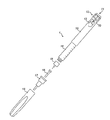
図1は、注射デバイス1の分解図であり、注射デバイス1は、たとえば、SanofiのSolostar(登録商標)というインスリン注射ペンを表すことができる。
FIG. 1 is an exploded view of the
図1の注射デバイス1は、ハウジング10を含み、インスリン容器14を収容する充填済みの使い捨て注射ペンであり、インスリン容器14に針15を取り付けることができる。針は、内側ニードルキャップ16および外側ニードルキャップ17によって保護されており、内側ニードルキャップ16および外側ニードルキャップ17は、キャップ18によって覆うことができる。注射デバイス1から放出予定のインスリン用量は、投薬量ノブ12を回すことによって選択することができ、次いで、この選択用量が、投薬量窓13を介して、たとえばいわゆる国際単位(IU)の倍数で表示される。1IUは、約45.5マイクログラムの純結晶インスリン(1/22mg)と生物学的に同等である。投薬量窓13内に表示される選択用量の一例は、たとえば、図1に示すように、30IUとすることができる。選択用量は、異なる方法で、たとえば電子ディスプレイを用いて、同様に表示することもできることに留意されたい。
The
投薬量ノブ12を回すことで、機械的なクリック音が生じ、使用者に音響フィードバックを提供する。投薬量窓13内に表示される数字は、ハウジング10内に収容されたスリーブ上に印刷されており、スリーブは、インスリン容器14内のピストンと機械的に相互作用する。針15が患者の皮膚部分内へ刺し込まれ、次いで注射ボタン11が押されたとき、表示窓13内に表示されたインスリン用量が、注射デバイス1から放出される。注射ボタン11が押された後、注射デバイス1の針15が特定の時間にわたって皮膚部分内に留まったとき、高い割合の用量が実際に患者の体内へ注射される。インスリン用量の放出によっても機械的なクリック音が生じるが、この音は、投薬量ノブ12を使用するときに生じる音とは異なる。
Turning the
注射デバイス1は、インスリン容器14が空になるまで、または注射デバイス1の有効期日(たとえば、最初の使用から28日間)に到達するまで、数回の注射プロセスに対して使用することができる。
The
さらに、注射デバイス1を初めて使用する前に、たとえば2単位のインスリンを選択し、針15が上向きの状態で注射デバイス1を保持しながら注射ボタン11を押すことによって、いわゆる「プライムショット」を実行し、インスリン容器14および針15から空気を除去することが必要になることがある。
Furthermore, before using the
提示を簡単にするために、以下、例示として、放出用量は注射用量に実質上対応し、したがって、たとえば次に注射予定の用量に対する提案を行うとき、この用量は注射デバイスによって放出されるべき用量に等しいと仮定する。しかし当然ながら、放出用量と注射用量との間の差(たとえば、損失)を考慮に入れることができる。 In order to simplify presentation, in the following, by way of example, the released dose substantially correspond to the injected dose, and thus this dose should be released by the injection device, for example when making a suggestion for the dose to be injected next Assume that it is equal to However, of course, the difference (e.g. loss) between the emitted dose and the injected dose can be taken into account.
図2aは、図1の注射デバイス1に解放可能に取り付け予定の補足デバイス2の一実施形態の概略図である。補足デバイス2は、図1の注射デバイス1のハウジング10を取り巻くように構成された嵌合ユニットを有するハウジング20を含み、したがって、補足デバイス2は、注射デバイス1のハウジング10上にぴったりと位置するが、それにもかかわらず、たとえば注射デバイス1が空になり、交換しなければならないときは、注射デバイス1から取り外し可能である。図2aは、非常に概略的な図であり、物理的な配置の詳細は、図2bを参照しながら以下に説明する。
FIG. 2a is a schematic view of one embodiment of a supplemental device 2 to be releasably attached to the
補足デバイス2は、注射デバイス1から情報を集める光および音響センサを収容する。情報は、補足デバイス2の表示ユニット21を介して表示される。注射デバイス1の投薬量窓13は、注射デバイス1に取り付けられたときの補足デバイス2によって遮られる。
The supplemental device 2 contains light and acoustic sensors that collect information from the
補足デバイス2は、ボタン22として概略的に示すように、3つのユーザ入力トランスデューサ(user input transducer)をさらに含む。これらの入力トランスデューサ22は、使用者が補足デバイス2をオン/オフにすること、動作をトリガすること(たとえば、別のデバイスとの連結もしくはペアリングを確立すること、および/もしくは補足デバイス2から別のデバイスへの情報の伝送をトリガすること)、または何かを確認することを可能にする。
The supplemental device 2 further includes three user input transducers, as schematically illustrated as
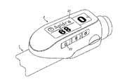
図2bは、図1の注射デバイス1に解放可能に取り付け予定の補足デバイス2の第2の実施形態の概略図である。補足デバイス2は、図1の注射デバイス1のハウジング10を取り巻くように構成された嵌合ユニットを有するハウジング20を含み、したがって、補足デバイス2は、注射デバイス1のハウジング10上にぴったりと位置するが、それにもかかわらず注射デバイス1から取り外し可能である。
FIG. 2b is a schematic view of a second embodiment of a supplemental device 2 to be releasably attached to the
情報は、補足デバイス2の表示ユニット21を介して表示される。注射デバイス1の投薬量窓13は、注射デバイス1に取り付けられたときの補足デバイス2によって遮られる。
The information is displayed via the
補足デバイス2は、3つのユーザ入力ボタンまたはスイッチをさらに含む。第1のボタン22は電源オン/オフボタンであり、このボタンを介して、補足デバイス2をたとえばオンおよびオフにすることができる。第2のボタン33は、通信ボタンである。第3のボタン34は、確認またはOKボタンである。ボタン22、33、34は、任意の適した形の機械スイッチとすることができる。これらの入力ボタン22は、使用者が補足デバイス2をオン/オフにすること、動作をトリガすること(たとえば、別のデバイスとの連結もしくはペアリングを確立すること、および/もしくは補足デバイス2から別のデバイスへの情報の伝送をトリガすること)、または何かを確認することを可能にする。
Supplemental device 2 further includes three user input buttons or switches. The
図2cは、図1の注射デバイス1に解放可能に取り付け予定の補足デバイス2の第3の実施形態の概略図である。補足デバイス2は、図1の注射デバイス1のハウジング10を取り巻くように構成された嵌合ユニットを有するハウジング20を含み、したがって、補足デバイス2は、注射デバイス1のハウジング10上にぴったりと位置するが、それにもかかわらず注射デバイス1から取り外し可能である。
FIG. 2c is a schematic view of a third embodiment of a supplemental device 2 to be releasably attached to the
情報は、補足デバイス2の表示ユニット21を介して表示される。注射デバイス1の投薬量窓13は、注射デバイス1に取り付けられたときの補足デバイス2によって遮られる。
The information is displayed via the
補足デバイス2は、タッチセンシティブ入力トランスデューサ35をさらに含む。補足デバイス2はまた、単一のユーザ入力ボタンまたはスイッチ22を含む。ボタン22は電源オン/オフボタンであり、このボタンを介して、補足デバイス2をたとえばオンおよびオフにすることができる。タッチセンシティブ入力トランスデューサ35を使用して、動作をトリガすること(たとえば、別のデバイスとの連結もしくはペアリングを確立すること、および/もしくは補足デバイス2から別のデバイスへの情報の伝送をトリガすること)、または何かを確認することができる。
The supplemental device 2 further includes a touch
図3aおよび図3bは、補足デバイス(図2aおよび図2bの補足デバイスなど)を注射デバイスとともに使用するときのデバイス間における可能な機能分布を示す。 Figures 3a and 3b illustrate possible functional distributions between devices when using supplemental devices (such as the supplemental devices of Figures 2a and 2b) with an injection device.
図3aの配列4では、補足デバイス41(図2aおよび図2bの補足デバイスなど)は、注射デバイス40からの情報を決定し、この情報(たとえば、注射予定の薬剤のタイプおよび/または用量)を血糖監視システム42に(たとえば、有線または無線接続を介して)提供する。
In array 4 of FIG. 3a, the supplemental device 41 (such as the supplemental device of FIGS. 2a and 2b) determines information from the
血糖監視システム42(たとえば、デスクトップコンピュータ、パーソナルデジタルアシスタント、移動電話、タブレットコンピュータ、ノートブック、ネットブック、またはウルトラブックとして実施することができる)は、患者がこれまでに受けた注射を記録する(放出用量に基づいて、たとえば放出用量と注射用量が同じであると仮定すること、または放出用量に基づいて注射用量を決定し、たとえば所定の割合の放出用量が患者によって完全には受けられないと仮定することによる)。血糖監視システム42は、たとえば、この患者に対する次の注射のインスリンのタイプおよび/または用量を提案することができる。この提案は、この患者によって受けられた1つまたはそれ以上の過去の注射に関する情報と、血糖計43によって測定され、血糖監視システム42に(たとえば、有線または無線接続を介して)提供される現在の血糖レベルとに基づいて行うことができる。そこで、血糖計43は、患者の小さい血液プローブ(たとえば、キャリア材料上)を受け、この血液プローブに基づいて患者の血糖レベルを決定するように構成された別個のデバイスとして実施することができる。しかし、血糖計43はまた、患者内へ、たとえば患者の目の中または皮膚の下に少なくとも一時的に移植されるデバイスとすることもできる。
The blood glucose monitoring system 42 (eg, which can be implemented as a desktop computer, personal digital assistant, mobile phone, tablet computer, notebook, netbook or ultrabook) records the injections the patient has received so far ( Based on the released dose, for example, assuming that the released dose and the injected dose are the same, or based on the released dose, determining the injected dose, for example, a predetermined percentage of the released dose is not completely received by the patient By assumption). Blood
図3bは、図3aの血糖計43が図3aの血糖監視システム42内へ含まれ、したがって図3bの修正された血糖監視システム42’が得られる修正された配列4’である。図3aの注射デバイス40および補足デバイス41の機能は、この修正による影響を受けない。また、血糖監視システム42’内へ組み合わされた血糖監視システム42および血糖計43の機能は基本的に変化しないが、ここでは両者が同じデバイス内に含まれており、したがって、これらのデバイス間の外部の有線または無線通信が不要になる。しかし、血糖監視システム42と血糖計43との間の通信は、システム42’内で行われる。
Fig. 3b is a modified arrangement 4 'in which the
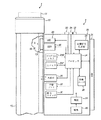
図4は、図1の注射デバイス1に取り付けられた状態の図2aの補足デバイス2の概略図を示す。
FIG. 4 shows a schematic view of the complementary device 2 of FIG. 2a in the state of being attached to the
補足デバイス2のハウジング20により、複数の構成要素が含まれる。これらはプロセッサ24によって制御され、プロセッサ24は、たとえば、マイクロプロセッサ、デジタル信号プロセッサ(DSP)、特定用途向け集積回路(ASIC)、フィールドプログラマブルゲートアレイ(FPGA)などとすることができる。プロセッサ24は、プログラムメモリ240内に記憶されたプログラムコード(たとえば、ソフトウェアまたはファームウェア)を実行し、主メモリ241を使用して、たとえば中間結果を記憶する。また、主メモリ241を使用して、実行された放出/注射に関するログブックを記憶することもできる。プログラムメモリ240は、たとえば、読み取り専用メモリ(ROM)とすることができ、主メモリは、たとえば、ランダムアクセスメモリ(RAM)とすることができる。
The
図2bに示すような実施形態では、プロセッサ24は第1のボタン22と相互作用し、第1のボタン22を介して、補足デバイス2をたとえばオンおよびオフにすることができる。第2のボタン33は、通信ボタンである。第2のボタンを使用して、別のデバイスとの連結の確立をトリガし、または別のデバイスへの情報の伝送をトリガすることができる。第3のボタン34は、確認またはOKボタンである。第3のボタン34を使用して、補足デバイス2の使用者に提示された情報を認めることができる。
In the embodiment as shown in FIG. 2b, the
図2cに示すような実施形態では、ボタン33、34の2つを省略することができる。代わりに、1つまたはそれ以上の容量センサまたは他のタッチセンサが設けられる。
In the embodiment as shown in FIG. 2c, two of the
プロセッサ24は、ここでは液晶ディスプレイ(LCD)として実施される表示ユニット21を制御する。表示ユニット21を使用して、たとえば注射デバイス1の現在の設定または投与予定の次の注射に関する情報を、補足デバイス2の使用者へ表示する。表示ユニット21はまた、たとえばユーザ入力を受けるために、タッチスクリーンディスプレイとして実施することもできる。
The
プロセッサ24はまた、投薬量窓13の画像を取り込むことが可能な光学式文字認識(OCR)リーダとして実施される光センサ25を制御する。投薬量窓13には、現在選択されている用量が表示されている(注射デバイス1内に収容されたスリーブ19上に印刷された数字による。これらの数字は、投薬量窓13を通して見ることができる)。OCRリーダ25は、取り込まれた画像から文字(たとえば、数字)を認識し、この情報をプロセッサ24に提供することがさらに可能である。別法として、補足デバイス2内のユニット25は、単に画像を取り込み、取り込まれた画像に関する情報をプロセッサ24に提供する光センサ、たとえばカメラとすることができる。次いで、プロセッサ24は、取り込まれた画像上でOCRの実行を担う。
The
プロセッサ24はまた、現在選択されている用量が表示されている投薬量窓13を照明するように、発光ダイオード(LED)29などの光源を制御する。光源の前で、拡散器、たとえば1片のアクリルガラスから作られた拡散器を使用することができる。さらに、光センサは、拡大(たとえば、3:1を超える拡大)をもたらすレンズ(たとえば、非球面レンズ)を含むことができる。
プロセッサ24は、注射デバイス1のハウジング10の光学的特性、たとえば色または陰影を決定するように構成された光度計26をさらに制御する。光学的特性は、ハウジング10の特有の部分にのみ存在することができ、たとえば、注射デバイス1内に含まれるスリーブ19またはインスリン容器の色または色コーディングとすることができ、この色または色コーディングは、たとえば、ハウジング10内(および/またはスリーブ19内)のさらなる窓を通して見えるようにすることができる。次いで、この色に関する情報は、プロセッサ24に提供され、次いで、プロセッサ24は、注射デバイス1のタイプまたは注射デバイス1内に収容されたインスリンのタイプを決定することができる(たとえば、SoloStar Lantusは紫色を有し、SoloStar Apidraは青色を有する)。別法として、光度計26の代わりにカメラユニットを使用することができ、次いで、ハウジング、スリーブ、またはインスリン容器の画像をプロセッサ24に提供して、画像処理を用いてハウジング、スリーブ、またはインスリン容器の色を決定することができる。さらに、光度計26の読み取りを改善するために、1つまたはそれ以上の光源を設けることができる。光源は、光度計26による色検出を改善するために、特定の波長またはスペクトルの光を提供することができる。光源は、たとえば投薬量窓13による望ましくない反射を回避または低減するように配置することができる。例示的な実施形態では、光度計26の代わりに、または光度計26に加えて、カメラユニットを導入し、注射デバイスおよび/またはその中に収容された薬剤に関係するコード(たとえば、バーコード、たとえば1次元または2次元バーコードとすることができる)を検出することができる。このコードは、たとえば、いくつかの例を挙げると、ハウジング10上または注射デバイス1内に収容された薬剤容器上に位置することができる。このコードは、たとえば、注射デバイスおよび/もしくは薬剤のタイプ、ならびに/またはさらなる特性(たとえば、有効期日)を示すことができる。
The
プロセッサ24は、注射デバイス1によって生じる音を感知するように構成された音響センサ27をさらに制御する(かつ/またはそこから信号を受ける)。そのような音は、たとえば、投薬量ノブ12を回すことによって用量がダイヤル設定されたとき、および/または注射ボタン11を押すことによって用量が放出/注射されたとき、および/またはプライムショットが実行されたときに生じることができる。これらの動作は、機械的に類似しているが、それにもかかわらず異なる音を出す(これはまた、これらの動作を示す電子音にも当てはまることができる)。音響センサ27および/またはプロセッサ24は、たとえば注射が行われた(プライムショットのみではない)ことを安全に認識することができるように、これらの異なる音を区別するように構成することができる。
The
プロセッサ24は、たとえば注射デバイス1の動作状態に関係することができる音響信号をたとえば使用者へのフィードバックとして生じさせるように構成された音響信号生成器23をさらに制御する。たとえば、音響信号は、注射予定の次の用量に対する注意として、またはたとえば誤使用の場合に警報信号として、音響信号生成器23によって発することができる。音響信号生成器は、たとえば、ブザーまたは拡声器として実施することができる。また、音響信号生成器23に加えて、または音響信号生成器23に対する代替として、触覚信号生成器(図示せず)を使用して、たとえば振動によって触覚フィードバックを提供することもできる。
The
プロセッサ24は、別のデバイスとの間で情報を無線で伝送しかつ/または受けるように構成された無線ユニット28を制御する。そのような伝送は、たとえば、無線伝送または光伝送に基づいて行うことができる。いくつかの実施形態では、無線ユニット28は、Bluetooth(登録商標)トランシーバである。別法として、無線ユニット28は、別のデバイスとの間で情報を有線で、たとえばケーブルまたはファイバ接続を介して伝送しかつ/または受けるように構成された有線ユニットに置き換えることができ、または補完することができる。データが伝送されるとき、伝達されるデータの単位(値)は、明示的または暗示的に画成することができる。たとえば、インスリン用量の場合、常に国際単位(IU)を使用することができ、またはそうでない場合、使用される単位は、明示的に、たとえばコード化された形式で伝達することができる。
The
プロセッサ24は、ペン1が存在するかどうかを検出し、すなわち補足デバイス2が注射デバイス1に連結されているかどうかを検出するように動作可能なペン検出スイッチ30からの入力を受ける。
The
電池32が、電源31を用いてプロセッサ24および他の構成要素に電力供給する。
A
したがって、図4の補足デバイス2は、注射デバイス1の状態および/または使用に関係する情報を決定することが可能である。この情報は、デバイスの使用者による使用のためにディスプレイ21上に表示される。この情報は、補足デバイス2自体によって処理することができ、または別のデバイス(たとえば、血糖監視システム)に少なくとも部分的に提供することができる。
Thus, supplemental device 2 of FIG. 4 is capable of determining information related to the status and / or use of
プロセッサ24は、プロセッサ配置を構成する。OCRリーダ25は、ダイヤル設定された薬剤の用量を検出するように動作可能なダイヤル設定用量検出器を構成する。OCRリーダ25はまた、その薬剤の用量が送達されたと決定する用量送達決定器(dose delivery determiner)を構成する。OCRリーダ25およびプロセッサ24はともに、送達された薬剤の数量を決定する数量決定器(quantity determiner)を構成する。プロセッサ24は、現在の時間を決定するように構成された時計の機能を提供する。
図5a〜5cは、本発明による方法の実施形態の流れ図である。これらの方法は、たとえば、補足デバイス2(図2aおよび図4参照)のプロセッサ24によって実行することができるが、図2bの補足デバイス2のプロセッサによって実行することもでき、たとえば、補足デバイス2のプログラムメモリ240内に記憶することができ、プログラムメモリ240は、たとえば、図6の有形記憶媒体60の形状をとることができる。
5a-5c are flow diagrams of embodiments of the method according to the invention. These methods can be performed, for example, by the
図5aは、図3aおよび図3bに示すシナリオで実行される方法工程を示し、注射デバイス40から補足デバイス41によって読み取られた情報は、血糖監視システム42または42’に提供されるが、血糖監視システム42または42’からの情報は受けない。
FIG. 5a shows the method steps performed in the scenario shown in FIGS. 3a and 3b, wherein the information read by the supplemental device 41 from the
流れ図500は、たとえば、補足デバイスがオンにされ、またはその他の方法で起動されたときに始まる。工程501で、たとえば、すでに上述したように、色認識に基づいて、または注射デバイスもしくはその構成要素上に印刷されたコードの認識に基づいて、注射デバイスによって提供される薬剤、たとえばインスリンのタイプが決定される。患者が常に同じタイプの薬剤を摂取し、注射デバイスをこの単一のタイプの薬剤のみとともに使用する場合、薬剤のタイプの検出は不要になることがある。さらに、薬剤のタイプの決定は、その他の方法で確実にすることもできる(たとえば、補足デバイスが1つの特有の注射デバイスのみとともに使用可能な図4に示す鍵−溝ペアによる。次いでこの注射デバイスは、この単一のタイプの薬剤のみを提供することができる)。
Flow diagram 500 begins, for example, when the supplemental device is turned on or otherwise activated. In
工程502で、上記のように、たとえば注射デバイスの投薬量窓上に示される情報のOCRによって、現在選択されている用量が決定される。次いで、工程503で、この情報が注射デバイスの使用者に表示される。
At
工程504で、たとえば上記の音認識によって、放出が行われたかどうかが確かめられる。そこでは、注射デバイスによって生じるそれぞれ異なる音に基づいて、かつ/または放出用量に基づいて(たとえば、わずかな用量、たとえば所定の単位量未満、たとえば4もしくは3単位は、プライムショットに属すると見なすことができ、より大きい用量は、実際の注射に属すると見なされる)、プライムショットと実際の注射(生体内)を区別することができる。
At
放出が行われた場合、決定されたデータ、すなわち選択用量、および該当する場合、薬剤(たとえば、インスリン)のタイプは、主メモリ241内に記憶され、このデータは後に、主メモリ241から別のデバイス、たとえば血糖監視システムへ伝送することができる。放出の性質に関する区別が行われた場合、たとえば放出がプライムショットまたは実際の注射として実行された場合、この情報もまた、主メモリ241内に記憶することができ、場合によっては後に伝送することができる。注射が実行された場合、工程505で、用量がディスプレイ21上に表示される。また、最後の注射からの時間が表示される。最後の注射からの時間は、注射直後は0または1分である。最終用量からの時間は、断続的に表示することができる。たとえば、最終用量からの時間は、注射された薬剤の名称または他の識別情報、たとえばApidraまたはLantusと交互に表示することができる。
If a release takes place, the determined data, ie the selected dose, and, if applicable, the type of drug (eg insulin) are stored in the
工程504で放出が実行されなかった場合、工程502および503が繰り返される。
If no release was performed at
送達用量および時間データの表示後、流れ図500は終了する。
After displaying the delivered dose and time data, the
図5bは、光センサのみの使用に基づいて選択用量が決定されるときに実行される例示的な方法工程をより詳細に示す。たとえば、これらの工程は、図5aの工程502で実行することができる。
FIG. 5b shows in more detail exemplary method steps performed when the selected dose is determined based on the use of only light sensors. For example, these steps can be performed at
工程901で、補足デバイス2の光センサ25などの光センサによって、サブ画像が取り込まれる。取り込まれたサブ画像は、たとえば、注射デバイス1の投薬量窓13の少なくとも一部の画像であり、この画像内には、現在選択されている用量が表示されている(たとえば、投薬量窓13を通して見ることができる注射デバイス1のスリーブ19上に印刷された数字および/または目盛りによる)。たとえば、取り込まれたサブ画像は、低い分解能を有することができ、かつ/またはスリーブ19のうち投薬量窓13を通して見ることができる部分の一部のみを示すことができる。たとえば、取り込まれたサブ画像は、注射デバイス1のスリーブ19のうち投薬量窓13を通して見ることができる部分上に印刷された数字または目盛りを示す。画像を取り込んだ後、この画像は、たとえば、次のようにさらに処理される:
以前に取り込まれた背景画像による分割;
さらなる評価のために画素数を低減させるための画像のビニング;
照明の強度変動を低減させるための画像の正規化;
画像のシャーリング;および/または
固定の閾値との比較による画像の2値化。
At
Segmentation by previously captured background image;
Image binning to reduce the number of pixels for further evaluation;
Image normalization to reduce intensity variations of the illumination;
Image shilling; and / or image binarization by comparison with a fixed threshold.
該当する場合、たとえば十分に大きい光センサ(たとえば、十分に大きい画素を有するセンサ)が使用される場合、これらの工程のいくつかまたはすべてを省略することができる。 Where applicable, some or all of these steps can be omitted, for example when a sufficiently large light sensor (eg, a sensor with a sufficiently large pixel) is used.
工程902で、取り込まれたサブ画像に変化があるか否かが決定される。たとえば、現在取り込まれているサブ画像を以前に取り込まれたサブ画像と比較して、変化があるか否かを決定することができる。そこで、以前に取り込まれたサブ画像との比較は、以前に取り込まれたサブ画像のうち現在のサブ画像が取り込まれる直前に取り込まれたサブ画像、および/または以前に取り込まれたサブ画像のうち現在のサブ画像が取り込まれる前の指定の期間(たとえば、0.1秒)内に取り込まれたサブ画像に制限することができる。この比較は、現在取り込まれているサブ画像および以前に取り込まれたサブ画像上で実行されるパターン認識などの画像分析技法に基づいて行うことができる。たとえば、投薬量窓13を通して見ることができ、現在取り込まれているサブ画像内および以前に取り込まれたサブ画像内に示される目盛りおよび/または数字のパターンが変化したかどうかを分析することができる。たとえば、特定の寸法および/または縦横比を有する画像内のパターンを検索することができ、これらのパターンを、以前に保存されたパターンと比較することができる。工程901および902は、取り込まれた画像内の変化の検出に対応することができる。
At
工程902でサブ画像内に変化があると決定された場合、工程901が繰り返される。そうでない場合、工程903で、補足デバイス2の光センサ25などの光センサによって、画像が取り込まれる。取り込まれた画像は、たとえば、注射デバイス1の投薬量窓13の画像であり、この画像内には、現在選択されている用量が表示されている(たとえば、投薬量窓13を通して見ることができる注射デバイス1のスリーブ19上に印刷された数字および/または目盛りによる)。たとえば、取り込まれた画像は、取り込まれたサブ画像の分解能より高い分解能を有することができる。取り込まれた画像は、少なくとも、投薬量窓13を通して見ることができる注射デバイス1のスリーブ19上に印刷された数字を示す。
If
工程904で、工程903で取り込まれた画像上で光学式文字認識(OCR)が実行され、注射デバイス1のスリーブ19上に印刷された投薬量窓13を通して見ることができる数字を認識する。それは、これらの数字が(現在の)選択用量に対応するからである。認識された数字に応じて、選択用量が決定され、たとえば認識された数字に選択用量を表す値を設定することによって決定される。
At
工程905で、決定された選択用量に変化があるか否か、および場合により、決定された選択用量がゼロに等しくないか否かが決定される。たとえば、現在決定されている選択用量を以前に決定された選択用量と比較して、変化があるか否かを決定することができる。そこで、以前に決定された選択用量との比較は、以前に決定された選択用量のうち現在の選択用量が決定される前の指定の期間(たとえば、3秒)内に決定された選択用量に制限することができる。決定された選択用量に変化がない場合、また場合により、決定された選択用量がゼロに等しくない場合、現在決定されている選択用量は、さらなる処理のために(たとえば、プロセッサ24へ)戻される/送られる。
At
したがって、投薬量ノブ12の最後の回転が3秒より前である場合、選択用量が決定される。投薬量ノブ12が3秒以内または3秒より後に回されており、新しい位置が3秒を超えて変化していない場合、この値が、決定された選択用量と見なされる。
Thus, if the last rotation of the
図5cは、音響および光センサの使用に基づいて選択用量が決定されるときに実行される方法工程をより詳細に示す。たとえば、これらの工程は、図5aの工程502で実行することができる。
FIG. 5c shows in more detail the method steps performed when the selected dose is determined based on the use of acoustic and light sensors. For example, these steps can be performed at
工程1001で、補足デバイス2の音響センサ27などの音響センサによって音が取り込まれる。
At
工程1002で、取込み音がクリック音であるか否かが決定される。取込み音は、たとえば、注射デバイス1の投薬量ノブ12を回すことによって用量がダイヤル設定されるとき、および/または注射ボタン11を押すことによって用量が放出/注射されるとき、および/またはプライムショットが実行されるときに生じるクリック音とすることができる。取込み音がクリック音でない場合、工程1001が繰り返される。そうでない場合、工程1003で、補足デバイス2の光センサ25などの光センサによって、画像が取り込まれる。工程1003は、流れ図900の工程903に対応する。
At
工程1004で、工程1003で取り込まれた画像上でOCRが実行される。工程1004は、流れ図900の工程904に対応する。
At
工程1005で、決定された選択用量に変化があるか否か、および場合により、決定された選択用量がゼロに等しくないか否かが決定される。工程1005は、流れ図900の工程905に対応する。
At step 1005, it is determined if there is a change in the determined selected dose and, optionally, if the determined selected dose is not equal to zero. Step 1005 corresponds to step 905 of
補足デバイスの電力消費に関しては、図5bに示すように画像またはサブ画像を恒久的に取り込むことが、典型的には、マイクロフォンなどの音響センサを聞くことより多くの電力を消費するため、図5cに示す音響手法にはわずかな利点があることがある。 With regard to the power consumption of the supplementary device, permanently capturing the image or sub-image as shown in FIG. 5 b typically consumes more power than listening to an acoustic sensor such as a microphone, FIG. The acoustic approach shown in may have slight advantages.
図6は、本発明の態様によるプログラムコード62を有するコンピュータプログラム61を含む有形記憶媒体60(コンピュータプログラム製品)の概略図である。このプログラムコードは、たとえば、補足デバイス内に収容されたプロセッサ、たとえば図2aおよび図4の補足デバイス2のプロセッサ24によって実行することができる。たとえば、記憶媒体60は、図4の補足デバイス2のプログラムメモリ240を表すことができる。記憶媒体60は、固定のメモリとすることができ、またはたとえばメモリスティックもしくはカードなどの取り外し可能なメモリとすることができる。
FIG. 6 is a schematic diagram of a tangible storage medium 60 (computer program product) comprising a
最後に、図7は、本発明の一実施形態による様々なデバイス(たとえば、図3aまたは図3bに示すシナリオにおける図4の注射デバイス1および補足デバイス2)間の情報の流れを示す情報シーケンス図7である。注射デバイス1の状態および/または使用は、その投薬量窓の外観、注射デバイス1によって生成される音、およびハウジングの色に影響を与える。この情報は、補足デバイス2のセンサ25、26、27、30によってそれぞれOCR信号、音響センサ信号、および光度計信号に変換され、これらの信号は、補足デバイス2のプロセッサ24によって、それぞれダイヤル設定された用量、注射/ダイヤル設定動作、およびインスリンのタイプに関する情報に変換される。次いで、この情報は、補足デバイス2によって血糖監視システム42に提供される。この情報の一部またはすべてが、ディスプレイ21を介して使用者に表示される。
Finally, FIG. 7 is an information sequence diagram showing the flow of information between the various devices (eg,
上記で詳細に説明したように、本発明の実施形態は、標準的な注射デバイス、特にインスリンデバイスと血糖監視システムとの連結を有用かつ生産的に可能にする。 As described in detail above, embodiments of the present invention make possible a useful and productive connection of a standard injection device, in particular an insulin device, with a blood glucose monitoring system.
本発明の実施形態は、血糖監視システムが無線または他の通信能力を有すると仮定して、この連結を可能にするために補足デバイスを導入する。 Embodiments of the present invention introduce supplemental devices to enable this connection, assuming that the blood glucose monitoring system has wireless or other communication capabilities.
血糖監視システムとインスリン注射デバイスとの間の連結から得られる利益は、とりわけ、注射デバイスの使用者による間違いの低減、および取扱い工程の低減であり、インスリン注射ユニットから血糖監視システム、特に注射された最終用量および最新の血糖値に基づいて次の用量に関する案内を提供する機能を有する血糖監視システムへの手動の伝達が不要になる。 The benefit obtained from the connection between the blood glucose monitoring system and the insulin injection device is, inter alia, the reduction of errors by the user of the injection device and the reduction of handling steps, the blood glucose monitoring system from the insulin injection unit, in particular injected Manual communication to the blood glucose monitoring system with the function of providing guidance on the next dose based on the final dose and the latest blood glucose level is not required.
上記の例示的な実施形態を参照して説明したように、使用者/患者が新しいインスリンペンを入手したとき、使用者は、このペンに補足デバイスを取り付ける。補足デバイスは、注射用量を読み出す。補足デバイスはまた、インスリン滴定能力を有する血糖監視システムへこの注射用量を伝達することができる。複数のインスリンを摂取する患者の場合、補足デバイスは、デバイス構造をインスリンタイプと認識し、この情報を血糖監視システムへ伝送することもできる。 As described with reference to the above exemplary embodiments, when the user / patient obtains a new insulin pen, the user attaches a supplemental device to the pen. The supplemental device reads the injection dose. The supplemental device can also deliver this injected dose to a blood glucose monitoring system that has insulin titration capability. In the case of patients taking multiple insulins, the supplemental device may also recognize the device structure as an insulin type and transmit this information to the blood glucose monitoring system.
例示的な実施形態では、ディスプレイ、たとえば図2aおよび図4のLCDディスプレイ21上に示される情報を音信号に変換することもでき、この音信号は、たとえば音響信号生成器23を使用してプロセッサ24によって実施されるテキストを音声に変換する機能によって、スピーカを通して使用者に再生される。したがって、視覚障害のある使用者は、ダイヤル設定された用量、推奨される用量、推奨される投与時間などの補足デバイス2の情報への改善されたアクセスを有することができる。
In an exemplary embodiment, the information shown on the display, for example the
本発明の実施形態を使用するとき、使用者はとりわけ、以下の利点を有する: Among other things, the user has the following advantages when using embodiments of the present invention:
使用者は、最も好都合な使い捨てのインスリン注射器を使用することができる。 The user can use the most convenient disposable insulin syringes.
補足デバイスは、取り付け可能および取り外し可能(再利用可能)である。 Supplemental devices are attachable and removable (reusable).
注射用量情報は、血糖監視システムへ自動的に伝達することができる(伝達の間違いは生じなくなる)。このため、血糖監視システムが摂取予定の用量を計算するとき、改善された用量案内を得ることができる。 Injection dose information can be automatically transmitted to the blood glucose monitoring system (errors in transmission will not occur). Thus, improved dose guidance can be obtained when the blood glucose monitoring system calculates the dose to be taken.
手動データログブックを付ける必要をなくすことができる。 This eliminates the need for manual data log books.
さらに、本発明によって提案される補足デバイスを導入するとき、患者はまた、たとえば、薬剤(たとえば、インスリンまたはヘパリン)の最初の用量が注射されてから適当な時間後、アラーム信号を受けることによって、次の用量を注射することを思い出すことができる。 In addition, when introducing the supplemental device proposed by the present invention, the patient may also receive an alarm signal, for example, by a suitable time after the first dose of the drug (eg insulin or heparin) has been injected. It can be remembered to inject the next dose.
注射用量情報は、たとえば任意の用量計算もしくは任意の他の該当する治療用案内計算に対する入力として、またはアラーム信号の生成のために、たとえば次の用量を摂取することを使用者に思い出させるために、任意のコンピュータ化システムへ伝達することができる。 The injection dose information may, for example, remind the user to take the next dose, for example as input to any dose calculation or any other relevant guidance calculation or for the generation of an alarm signal. , Can be transmitted to any computerized system.
図8は、補足デバイス2の動作を示すために次に使用される図面である。図8は、部分的な流れ図および部分的な状態図である。 FIG. 8 is a drawing used next to show the operation of the supplementary device 2. FIG. 8 is a partial flow diagram and partial state diagram.
以下、「I」で始まる参照番号でユーザ入力を示し、「D」で始まる参照番号で表示または状態を示し、「E」で始まる参照番号で図面の他の要素、たとえば補足デバイスによって行われるチェックおよび説明的情報を示す。 In the following, the user input is indicated by a reference number beginning with "I", the indication or status is indicated by a reference number beginning with "D", and the checks performed by the other elements of the drawing, eg supplementary devices, by a reference number beginning with "E" And show descriptive information.
以下、ハードウェアディスプレイ21と表示される画像との間の混乱を回避するため、ディスプレイ21をLCD21と呼び、表示される画像を表示と呼ぶことができる。しかし、LCD21は、任意の適した形の表示ハードウェアとすることができる。
Hereinafter, in order to avoid confusion between the
最初、補足デバイスは電源が切られている。これは、D1に示す表示を提供する。 Initially, supplemental devices are powered off. This provides the indication shown in D1.
D1はまた、補足デバイスのユーザインターフェース機能の概略的な配置を示す。特に、LCD21および確認/OKボタン34を備える補足デバイス2の最上面が示されている。確認/OKボタン34は、この例ではLCD21の左に位置するが、他の実施形態では代替の位置を有することができる。補足デバイス2の側面には、電源オン/オフボタン22および通信ボタン33が位置する。ここに示すように、通信ボタン33および電源オン/オフボタン22は、補足デバイス2の同じ側に位置するが、他の実施形態では、これらのボタンは異なる場所に位置する。たとえば、いくつかの実施形態では、電源オン/オフボタン22は、通信ボタン33に対してLCD21の反対側に位置する。いくつかの他の実施形態では、通信ボタン33および/または電源オン/オフボタン22は、補足デバイス2の上面に位置する。
D1 also shows a schematic arrangement of the user interface function of the supplementary device. In particular, the top side of the supplementary device 2 comprising the
入力I1で、使用者は電源オン/オフボタン22を押す。入力I1は、補足デバイス2によって検出される。特に、プロセッサ24は、電源オン/オフボタン22が比較的短い期間にわたって押されたことを検出する。他のユーザ入力も補足デバイスによって同様に検出され、場合によって、以下の説明で手短な説明を提供する。以下、「モード」および「状態」は、同じ事柄を示すために区別なく使用する;補足デバイス2がモードXにある場合、これは、状態Xにあるのと同じであることを意味する。
At input I 1, the user presses the power on / off
補足デバイス2がD1に示す状態にあるときに、補足デバイス2が図8に入力I2で示す電源オン/オフボタン22の長い押し下げを受けた場合、補足デバイス2は、D2に示す状態または表示に遷移する。ここで、LCD21上に電源オンプログレスバーが表示される。このプログレスバーは、電力または電池を示す記号を含み、また、電池の電力レベルに関するインジケータも含む。図8に示すように、この例では、電池の電力は、フル充電された電池の約3分の1である。補足デバイス2は、所定の時間、たとえば2または3秒にわたって、D2によって示す状態のままである。D2に示す状態に続いて、補足デバイス2は、4つの可能な状態の1つに遷移する。
When supplemental device 2 is in the state shown in D1, if supplemental device 2 receives a long depression of power on / off
プロセッサ24が検出スイッチ30の状態を調査することによって補足デバイスによって検出されたとき、補足デバイスが注射デバイス1上に取り付けられていない場合、補足デバイス2は、図8にD3によって示す状態に遷移する。ここで、補足デバイスは、ペンが存在しないことを示すグラフィックをLCD21上に提供する。これは、グラフィックのみ、テキストのみ、またはグラフィックとテキストの組合せとすることができる。
When the
補足デバイス2がD2によって示す状態にあるときに、補足デバイス2と注射ペン1との間の正確な位置合わせがないことを補足デバイス2が検出した場合、補足デバイスは、図8にD4によって示す状態へ進む。補足デバイス2と注射デバイス1との間の誤った位置合わせは、補足デバイスによって、OCRモジュール25および/または光度計26によって受けられた記号の調査によって検出することができる。
If the supplemental device 2 detects that there is no accurate alignment between the supplemental device 2 and the
第3に、補足デバイスがD2によって示す状態にあるとき、電池32がほとんど空であることを検出した場合、補足デバイスは、図8にD5によって示す低電池状態へ遷移する。ここで、電池警報グラフィックが提供される。これは、任意の適した形をとることができる。
Third, when the supplemental device is in the state indicated by D2, if the
補足デバイス2は、図8にD3、D4、およびD5によって示す3つの状態のいずれにも遷移しない場合、D6によって示す状態へ遷移する。これをデフォルト状態と呼ぶ。デフォルト状態では、補足デバイスは、最後の注射の詳細を示す。言い換えると、デフォルト状態では、補足デバイス2は、注射ペン1の最後の使用に関する情報を表示する。
The supplementary device 2 transitions to the state indicated by D6 if it does not transition to any of the three states indicated by D3, D4, and D5 in FIG. This is called the default state. By default, the supplemental device shows the details of the last injection. In other words, in the default state, the supplementary device 2 displays information on the last use of the
デフォルト状態D6はまた、D3によって示す取り付けられていない状態、D4によって示す誤った位置合わせ状態、またはD5によって示す低電池状態に続いて到達する。補足デバイス2は、所定の時間、たとえば3秒、5秒、または10秒にわたって、これらの直前の状態のいずれかに留まった後、D6に示すデフォルト状態へ遷移することができる。 The default state D6 also arrives following the unmounted state indicated by D3, the misaligned state indicated by D4, or the low cell state indicated by D5. The supplemental device 2 can transition to the default state shown at D6 after staying in any of these previous states for a predetermined time, for example 3 seconds, 5 seconds or 10 seconds.
D3によって示す取り付けられていない状態の場合、補足デバイス2は、代わりに、補足デバイス2が補足デバイス2と注射ペン1との間に正確な位置合わせがあることを検出するまで、D6によって示すデフォルト状態へ遷移しないようにすることができる。別法として、補足デバイスがD3によって示す取り付けられていない状態を通って遷移した後、補足デバイスが検出スイッチ30の状態を調査することによって、補足デバイス2が注射デバイス1上に取り付けられていることを検出するまで、補足デバイスはD6によって示すデフォルト状態に留まることができる。
In the unattached state indicated by D3, the supplemental device 2 will instead default by D6 until it detects that there is correct alignment between the supplemental device 2 and the
図8に表示D4によって示す位置合わせされていない状態に関しては、補足デバイス2が補足デバイス2と注射デバイス1との間の正確な位置合わせを検出するまで、補足デバイス2は位置合わせされていない状態に留まることができる。別法として、補足デバイス2は、D4によって示す位置合わせされていない状態からD6によって示すデフォルト状態へ遷移するが、補足デバイス2が補足デバイス2と注射デバイス1との間に正確な位置合わせがあることを検出するまで、デフォルト状態から進まないようにすることができる。
With respect to the unaligned condition shown by the display D4 in FIG. 8, the complementary device 2 is not aligned until the complementary device 2 detects the correct alignment between the supplemental device 2 and the
補足デバイスがD5によって示す低電池状態を通って遷移した後、図8にD6によって示すデフォルト状態に到達した場合、補足デバイス2は、低電池状態であることを周期的に示す。これは、デフォルト状態D6から垂れ下がるチェック工程E1によって実現される。チェック工程E1は、電池32がほとんど空であるかどうかを補足デバイス2が決定することを伴い、ほとんど空である場合、動作工程E2は、表示D5に示す警報を周期的に提供することを伴う。
After the supplemental device transitions through the low battery state indicated by D5, the supplemental device 2 periodically indicates that it is in the low battery state if it has reached the default state indicated by D6 in FIG. This is realized by the check step E1 hanging from the default state D6. The checking step E1 involves the supplementary device 2 determining whether the
補足デバイス2がD6によって示すデフォルト状態に到達する前に、D5によって示す低電池状態を通って遷移しなかった場合でも、チェック工程E1は周期的に実行される。したがって、補足デバイス2が図8にD6によって示すデフォルト状態にあり、かつ電池レベルがチェック工程E1で電池がほとんど空であると決定されるまで下がっているとき、動作工程E2は、補足デバイス2にD5によって示す低電池状態へ遷移させることを伴う。 Before the supplementary device 2 has reached the default state indicated by D6, the check step E1 is performed periodically, even if it has not transitioned through the low battery state indicated by D5. Thus, when the supplemental device 2 is in the default state shown by D6 in FIG. 8 and the battery level is lowered until the battery is determined to be almost empty in the checking step E1, the operating step E2 is It involves transitioning to the low battery state shown by D5.
低電池状態D5を通って遷移した後、電池32が交換され、またはその他の方法で補充されるまで、D5によって示す低電池表示が周期的に提供される。いくつかの実施形態では、D5に示す低電池表示は、補足デバイス2がデフォルト状態にあるときのみ提供される。これにより、デバイスが薬剤の用量の送達に関連して使用されているとき、および/または補足デバイス2が別のデバイスと通信しようとしているときに、低電池警報が使用者に提供されることを防止する。
After transitioning through the low battery state D5, a low battery indication, indicated by D5, is provided cyclically until the
図8には図示しないが、補足デバイス2が図にD6によって示すデフォルト状態にあるときに、補足デバイス2が電源オン/オフボタン22の長い押し下げを受けた場合、補足デバイスの電源が切られる。その後、デバイスは、図8にD1によって示すオフ状態になる。補足デバイス2は、電源オン/オフボタン22の長い押し下げに応答して、いずれの状態からでも電源を切ることができる。
Although not shown in FIG. 8, when the supplemental device 2 is in the default state indicated by D6 in the figure, if the supplemental device 2 receives a long depression of the power on / off
補足デバイス2は、使用者が投薬量ダイヤル12を回したことを検出したことに応答して、D6によって示すデフォルト状態から遷移することができる。これを図のI3に示す。これに応答して、補足デバイス2は、図8のD7に示す投薬量ダイヤル設定状態に入る。ここで、補足デバイス2は、注射ペン1に現在ダイヤル設定されている薬剤の用量をLCD21上に表示する。これは、OCRリーダ25によって注射デバイスから図を読み取ることによって、補足デバイス2に知られることとなる。この状態で、補足デバイス2はまた、注射デバイス1内に存在する薬剤のインジケーションを表示する。表示D7で、薬剤は、薬剤の名称を示すテキスト、この場合は「Apidra」の表示によって示される。
The supplemental device 2 can transition from the default state indicated by D6 in response to detecting that the user has turned the
現在設定されている用量は、投薬量ダイヤル設定状態において、D7に示す表示に任意の適した方法で示される。用量は、有利には、LCD21によって収容することができる最大の文字で示される。特に、活字の高さは、LCD21の高さに等しくすることができ、または少なくともLCD21の高さの80もしくは90%もしくはそれ以上の高さを有することができる。補足デバイスは、LCD21上に表示される用量値が注射ペンに現在ダイヤル設定されている用量に関することが使用者にとって明確になるように、任意の適した方法で表示D7を提供することができる。たとえば、表示された用量値の周りに提供されるグラフィック要素を点滅または明滅させることができる。別法として、用量値の文字自体を点滅または明滅させることもできる。別法として、背景を点滅または明滅させることもできる。
The currently set dose is indicated in the dose dial setting in any suitable manner on the display shown at D7. The dose is advantageously indicated by the largest letter that can be accommodated by the
投薬量ダイヤル12が所定の期間、たとえば0.5秒または1秒にわたって回されなかったことを補足デバイス2が検出したとき、これは、入力I3a(ただし実際には、入力はないこと)で検出され、補足デバイス2は、図8にダイヤル設定用量表示D7aによって示す用量ダイヤル設定状態へ遷移する。用量ダイヤル設定状態で、補足デバイス2は、LCD21に2つの異なる表示を提供させ、デバイス2は、周期的に一方の表示から他方の表示へ遷移し、そして再び元へ遷移する。D7aによって示す用量ダイヤル設定状態では、どちらの表示も、ダイヤル設定用量を含み、これは同じ位置に提供される。ダイヤル設定用量は、どちらの表示でも同じ方法で表示することができる。一方の表示は、注射デバイス1内に存在する薬剤を示す。この例では、これは、薬剤の名称を示すテキスト、この場合は「Apidra」によって示される。他方の表示は、薬剤の用量を送達することができるというインジケーションを含む。この例では、これは、確認/OKボタンとともに手のグラフィックによって提供される。
When the supplemental device 2 detects that the
D7aによって示す用量ダイヤル設定状態にある間に、補足デバイス2が図8に入力I3によって示す投薬量ダイヤル12をさらに回したことに関する入力を受けた場合、補足デバイスは再び、図にD7によって示す投薬量ダイヤル設定状態へ進む。
If the supplemental device 2 receives an input regarding further turning of the
デバイスがD7によって示す投薬量ダイヤル設定状態またはD7aによって示す用量ダイヤル設定状態にあるときに使用者によって確認/OKボタン34が動作されたことを補足デバイス2が検出した場合、この入力I4は、図8にD8によって示すここで注射状態への遷移を引き起こす。ここで注射状態では、注射が可能であることを使用者に示すグラフィックが提供される。
If the supplemental device 2 detects that the confirmation /
この段階で、使用者は、2つの選択肢を有する。使用者は、用量を変化させることができる。これは、使用者が確認/OKボタン34を選択し、次いで投薬量ダイヤラ12を回すことによって実現される。これは、補足デバイスによって入力I5として検出される。入力I5を検出したとき、補足デバイス2は、図8にD7によって示す用量ダイヤル設定状態に戻る。
At this stage, the user has two options. The user can change the dose. This is achieved by the user selecting the confirmation /
別法として、使用者は、薬剤を注射することができる。これは、補足デバイス2によって入力I6として検出される。入力I6は、図8にD9として示す投薬量送達状態への遷移を引き起こす。ここで、注射デバイス1にダイヤル設定された残りの用量がLCD21上に表示される。用量が送達されるにつれて、残りの用量は小さくなる。したがって、残りの用量値は、ダイヤル設定用量からゼロに向かってカウントダウンする。
Alternatively, the user can inject the drug. This is detected by the supplemental device 2 as input I6. Input I6 causes a transition to the dose delivery state shown as D9 in FIG. Here, the remaining dose set to the
使用者が全用量を送達しなかった場合、これは、確認/OKボタン34の押下を検出することによって、または使用者が投薬量ダイヤラ12を元へ戻したことを検出することによって、補足デバイスによって入力I7で検出される。入力I7は、図に表示D10で示す10秒カウントダウン状態への遷移を引き起こす。10秒が経過した後、補足デバイス2は、図8に表示D11によって示す一部用量送達状態へ遷移する。ここで、補足デバイス2は、注射ペン1を通って使用者へ送達された用量を表示する。送達された用量は、D7によって示す投薬量ダイヤル設定状態またはD7aによって示すダイヤル設定用量状態にあるときに補足デバイスによって検出されるダイヤル設定された用量から、入力I7が検出されたときに残っている用量を引いた値に等しい。この状態で、送達された薬剤も表示される。この例では、送達用量は、図8にD7およびD7aによって示す状態のいずれかによって提供される文字より小さい文字で示される。送達用量に対して垂直に、送達された薬剤のインジケーションが配置される。この状態へまたはこの状態から遷移すると、補足デバイス内のタイマ(図示せず)がリセットされる。タイマは、最終用量が送達されてからの経過時間を補足デバイス2が計算することを可能にする。表示D11によって示す状態からの遷移は、図8にD7によって示す状態に対して行われる。
If the user did not deliver the full dose, this is a supplemental device by detecting the pressing of the confirm /
別法として、補足デバイス2は、注射が完了したことを示す入力I8を検出することによって、D9によって示す用量送達状態から退出することができる。この場合、補足デバイスは、図8に表示D12によって示すカウントダウン状態へ遷移した。ここで、LCD21は、図にD10によって示すカウントダウン状態の表示内に提供されるアイコンと同じアイコンを備える。
Alternatively, supplemental device 2 can be withdrawn from the dose delivery state indicated by D9 by detecting input I8 indicating that the injection is complete. In this case, the supplementary device has transitioned to the countdown state indicated by display D12 in FIG. Here, the
10秒が経過した後、補足デバイス2は、図8に表示D13で示す針除去命令状態へ遷移する。ここで、補足デバイス2は、注射デバイス1の針を交換するべきであることを使用者に示すグラフィックを提供する。所定の時間後、または音響センサ27が存在する場合は針が交換されたことを検出したとき、補足デバイス2は、図8に表示D14によって示すリセット状態へ遷移する。ここで、送達用量の値が補足デバイス2内に記憶され、タイマ(図示せず)が開始される。タイマは、最終用量から経過した時間を示す値を提供する。リセット状態後、補足デバイス2は、図8にD6によって示すデフォルト状態へ遷移する。
After 10 seconds have elapsed, the supplemental device 2 transitions to the needle removal instruction state indicated by display D13 in FIG. Here, the supplemental device 2 provides a graphic that indicates to the user that the needle of the
補足デバイス2がD6によって示すデフォルト状態にあるときに、使用者が通信ボタン33を押したことを示す入力I9を補足デバイス2が検出した場合、補足デバイス2は、デフォルト状態から遷移する。ここで、補足デバイス2は、デバイスがアクセス可能であるかどうかを決定する。ここでのデバイスは、たとえば、血糖測定ユニット42である。工程S3における決定でデバイスがアクセス可能であることを示し、E4でデバイスが未知であると決定された場合、補足デバイス2は、図でD15によって示すペアリングプロセス状態に入る。この状態で、補足デバイス2は、検出されたデバイスとのペアリングを開始する。無線ユニット28がBluetooth(登録商標)トランシーバである場合、これは、Bluetooth(登録商標)規格にしたがってペアリングを開始することを伴う。D15によって示すペアリングプロセス状態では、Bluetooth(登録商標)のPIN番号がLCD21上に表示される。これには、このPIN番号が未知のデバイス上に表示されているものに整合することを使用者が確認することを要求するアイコンが付随する。補足デバイス2がE5でペアリングに失敗したと決定した場合、補足デバイス2は、図にD16によって示すBluetooth(登録商標)エラーメッセージ状態へ遷移する。この状態はまた、入力I9に続いて、E8でデバイスがアクセス可能でないと決定された場合に遷移される。D16によって示すBluetooth(登録商標)エラーメッセージ状態で、通信が可能でないことを示すアイコンがLCD21上に表示される。Bluetooth(登録商標)エラーメッセージ状態に続いて、たとえば所定の時間後、補足デバイス2は、D6によって示すデフォルト状態へ遷移する。
When the supplementary device 2 detects the input I9 indicating that the user has pressed the
ペアリング状態で、補足デバイスがE6でペアリングが完了したと決定した場合、補足デバイスは、D17によって示す短伝送状態へ遷移する。補足デバイスまた、入力I9に続いて、補足デバイスがE3でデバイスがアクセス可能であると決定し、E7でこのデバイスが既知のデバイスであると決定した場合、D6によって示すデフォルト状態からD17によって示す短伝送状態へ遷移する。 In the pairing state, if the supplementary device determines that the pairing is completed in E6, the supplementary device transitions to the short transmission state indicated by D17. Supplemental Device Also, following input I9, if the supplemental device determines that the device is accessible at E3 and determines that this device is a known device at E7, the default state indicated by D6 to the short state indicated by D17 Transition to the transmission state.
D17によって示す短伝送状態では、通信が進行中であることを示すアイコンまたはグラフィックがLCD21上に表示される。通信が完了した後、補足デバイス2は、D18によって示す伝送終了段階へ遷移する。ここで、補足デバイス2は、伝送が完了したことを示すグラフィックを提供する。伝送終了状態に続いて、補足デバイス2は、D6によって示すデフォルト状態へ遷移する。
In the short transmission state indicated by D17, an icon or graphic indicating that communication is in progress is displayed on the
D6によって示すデフォルト状態にあるとき、動作は次のように行われる。補足デバイス2は、補足デバイス2に電源が投入される時間の大部分にわたってデフォルト状態にあることが予期される。したがって、デフォルト状態にあるときの表示D6は、補足デバイスの使用者によって最も多く見られる可能性が高い表示である。 When in the default state indicated by D6, the operation takes place as follows. The supplemental device 2 is expected to be in the default state for most of the time the supplemental device 2 is powered on. Thus, the display D6 when in the default state is the display most likely to be seen by the user of the supplemental device.
デフォルト状態にあるとき、補足デバイスは、最終送達用量の詳細を使用者に示すように構成される。これらの詳細は、用量の数量および最終用量送達から経過した時間を含む。これらの詳細はまた、薬剤の識別情報を含む。 When in the default state, the supplemental device is configured to show the user the details of the final delivered dose. These details include the quantity of dose and the time elapsed from final dose delivery. These details also include drug identification information.
これらの実施形態では、これは、デフォルト状態で2つの異なる表示間を遷移することによって実現される。第1の表示は、図8に表示D6内で最も上に示されている。ここで、LCD21の2つの領域があることが理解されよう。左側の領域は、表示区域の約3分の2を占める。以下、この領域を最終用量領域と呼ぶ。LCD21の右側には、最終用量領域の右に別の領域がある。この例では、他方の領域は、注射ペン1にダイヤル設定された用量を表示する。LCD21の右側に表示される情報は、注射ペン1からのダイヤル設定値である。これは、LCD21に左側に表示される情報による影響を受けない。
In these embodiments, this is achieved by transitioning between two different displays in a default state. The first display is shown at the top in display D6 in FIG. It will be understood that there are two areas of the
図8のD6で最も上に示す第1の表示内の最終用量領域は、2つの区域に分割される。ここで、これらの区域は、上部区域および下部区域である。第1の区域、ここで下部区域には、最終送達用量が表示される。これは、用量をIUで示す数字の形である。 The final dose area in the first representation shown at the top of D6 in FIG. 8 is divided into two areas. Here, these areas are the upper area and the lower area. In the first area, here the lower area, the final delivered dose is displayed. This is in the form of numbers which indicate the dose in IU.
第2の区域には、最終用量が送達されてからの経過時間が表示される。ここで、これは、数字として表される時間として表示され、時間単位はローマ文字で表される。時間単位の表示は、使用者が最終用量からの時間の表示と用量の数量とを区別することを可能にする。第2の区域はまた、タイマまたは時計を示すグラフィックを含み、それによってこのメッセージを強調する。 The second area displays the time elapsed since the final dose was delivered. Here, this is displayed as time represented as a number, and the time unit is represented by Roman letters. The time unit display allows the user to distinguish between the display of time from the final dose and the dose quantity. The second area also contains a graphic showing the timer or clock, thereby highlighting this message.
図8のD6で最も下に示す第2の表示では、第1の区域は変化しない。したがって、第1の区域は、最終用量の数量を表示する。第2の区域は、最終用量から経過した時間を示さない。代わりに、第2の区域は、最終用量の薬剤を示す。ここで、これは、薬剤の名称を綴るテキスト、この場合「Apidra」によって示される。この場合も、第2の区域内に時計またはタイマアイコンが表示される。 In the second display shown at the bottom of D6 of FIG. 8, the first area does not change. Thus, the first area displays the final dose quantity. The second zone does not show the time elapsed from the final dose. Instead, the second area shows the final dose of drug. Here, this is indicated by a text that spells out the name of the drug, in this case "Apidra". Again, a clock or timer icon is displayed in the second area.
デフォルト状態で、補足デバイス2は、最も上に示す第1の表示と最も下に示す第2の表示との間で表示を周期的に遷移させる。遷移は、たとえば2秒ごとに行うことができる。 In the default state, the supplemental device 2 periodically transitions the display between the first display shown at the top and the second display shown at the bottom. The transition can be performed, for example, every two seconds.
図8に見ることができるように、用量表示領域21Bの第1の区域は、第2の区域より大きい。したがって、用量の数量を示すために使用される文字の高さは、最終用量から経過した時間または薬剤の識別情報を示すために使用される文字より大きい。したがって、使用者は、最終用量の数量を迅速かつ容易に、おそらく一目見ただけで決定することが可能である。 As can be seen in FIG. 8, the first area of the dose display area 21B is larger than the second area. Thus, the height of the letters used to indicate the dose quantity is greater than the letters used to indicate the time elapsed from the final dose or identification of the drug. Thus, the user can determine the final dose quantity quickly and easily, perhaps at first glance.
加えて、使用者は、最終用量から経過した時間を比較的容易に決定することが可能である。最終用量から経過した時間および用量の数量は、糖尿病を治療するために使用される薬剤の使用者にとって最も重要なパラメータである。これらのパラメータは、薬剤の次の用量を決定するとき、薬剤を送達するべき時間および必要とされる薬剤の数量の点から、使用者にとって最も重要である。 In addition, the user can relatively easily determine the time elapsed from the final dose. The time elapsed from the final dose and the dose quantity are the most important parameters for the user of the drug used to treat diabetes. These parameters are most important to the user in terms of time to deliver the drug and the quantity of drug needed when determining the next dose of drug.
したがって、デフォルト状態の提供およびその状態で補足デバイス2によって提供される表示は、薬剤が処方された症状を使用者がよりよく治療することを可能にすることができる。言い換えると、デフォルト状態にあるときの補足デバイスの機能は、使用者がより容易に自身の症状を治療することを可能にし、場合によっては使用者にとってよりよい治療を提供することができる。 Thus, the provision of a default condition and the indication provided by the supplemental device 2 in that condition may allow the user to better treat the condition for which the drug was prescribed. In other words, the functionality of the supplemental device when in the default state allows the user to more easily treat his / her condition, and in some cases may provide a better treatment for the user.
図2cおよび図9を参照しながら、代替実施形態について次に説明する。 An alternative embodiment will now be described with reference to FIGS. 2c and 9.
図2cに見ることができるように、補足デバイス2は、LCD21および電源オン/オフボタン22を備える。LCD21は、タッチセンシティブディスプレイであり、タッチセンシティブディスプレイを通じて、使用者は補足デバイスへ入力を提供することができる。したがって、タッチセンシティブLCD21はまた、図8および図2bの実施形態では通信ボタン33および確認/OKボタン34によって提供される機能を提供する。
As can be seen in FIG. 2 c, the supplementary device 2 comprises an
この実施形態による補足デバイスの動作は、図8を参照して説明した図2bのデバイスの動作にかなり類似している。図9では、同様の要素に対しては図8からの参照番号を保持し、ここでは図2cの実施形態と図2bの実施形態との間の動作の違いについてのみ説明する。図2bおよび図8のデバイスの機能および動作と同じ図2cのデバイスの機能および動作については、以下で議論しない。 The operation of the supplemental device according to this embodiment is quite similar to the operation of the device of FIG. 2b described with reference to FIG. In FIG. 9, for similar elements, the reference numbers from FIG. 8 are kept, and here only the difference in operation between the embodiment of FIG. 2c and the embodiment of FIG. 2b is described. The function and operation of the device of FIG. 2c that is identical to the function and operation of the device of FIGS. 2b and 8 will not be discussed below.
図9に表示D1によって示すデバイスオフ状態は、図8に示すデバイス動作の対応する状態に非常に類似している。この表示D1は、LCD21上に提供される全体的なレイアウトを示す。特に、表示の第1の領域21Bは表示領域21Bである。これは、図9のD1の表示の右側に示される。表示の第2の領域21Aは入力領域21Aである。これは、D1で右側に示される。入力領域21Aはまた、アクティブ表示領域21Bである。しかし、入力領域21Aは、ユーザ入力を受けることができる領域である。入力領域21Aは、適当なとき、特に補足デバイス2が特定の状態にあるときに、仮想ボタンの表示を含む。この実施形態では、入力領域21Aは常に、LCD21上の同じ場所に位置する。これにより、使用者の体験が簡単になる。他の実施形態では、入力領域21Aは、補足デバイスの状態に応じて位置を変化させることができる。入力領域21Aは、図2cに示すタッチセンシティブ入力35である。
The device off state shown by display D1 in FIG. 9 is very similar to the corresponding state of the device operation shown in FIG. This display D1 shows the overall layout provided on the
D1に示すデバイスオフ状態で、LCD21は空白である。LCD21が一領域で空白であるとき、その領域には何も表示されない。入力領域21Aが空白であるとき、仮想ボタンの輪郭を表示することができるが、仮想ボタン内には何も表示されない。
The
D2によって示す電源オフ進行状態で、入力領域21Aは空白のままであり、すなわち入力領域21A内には何も表示されない。この状態で、表示領域21Bは、電池32内に残っている電力量を示すインジケータを備える。このインジケータは、図8のD2に示すインジケータと同じであるが、寸法はより小さい。
In the power-off progress state indicated by D2, the input area 21A is left blank, that is, nothing is displayed in the input area 21A. In this state, the display area 21B includes an indicator that indicates the amount of power remaining in the
デバイスが取り付けられていない状態D3で、入力領域21Aは空白であり、ペンが連結されていないことを示すグラフィックが表示領域21B内に示される。D4に示すカメラ調整発行状態で、入力領域21Aは空白のままであり、表示領域21Bは、補足デバイス2と注射デバイス1との間の位置合わせがなされていないことを示す。表示D5によって示す低電池状態で、入力領域21Aは空白のままであり、表示領域21Bは、電池がほとんど空であることを示すアイコンを含む。
In the state D3 in which the device is not attached, the input area 21A is blank, and a graphic indicating that the pen is not connected is shown in the display area 21B. In the camera adjustment issuance state shown in D4, the input area 21A is left blank, and the display area 21B indicates that the complementary device 2 and the
デフォルト状態で、入力領域21Aは、通信の選択肢に関するアイコンを備える。この例では、入力領域21Aは、Bluetooth(登録商標)通信の選択肢を示すアイコンを備える。補足デバイス2は、デフォルト状態にあるとき、図8を参照して上述したように、入力領域21AにおけるLCD21への接触を含むユーザ入力I9に応答して、チェックE3およびE8を通って進むように構成される。
In the default state, the input area 21A includes an icon related to a communication option. In this example, the input area 21A includes an icon indicating a choice of Bluetooth (registered trademark) communication. When the supplemental device 2 is in the default state, it proceeds through checks E3 and E8 in response to user input I9 including contact to the
デフォルトモードにあるとき、表示の表示領域21Bは、図8のデフォルト状態における表示の第1の領域に関連して上述した表示を備える。 When in the default mode, the display area 21B of the display comprises the display described above in relation to the first area of the display in the default state of FIG.
デバイスがD6によって示すデフォルト状態にあるときに電池がほとんど空であることを補足デバイス2が検出したとき、チェックE1は、動作E2を周期的に引き起こすことができ、その結果、デバイスは電池がほとんど空である状態へ遷移し、D5に示す表示を提供する。別法として、補足デバイス2は、表示領域21B内に低電池アイコンを含むように構成することができる。これを、図9に表示D19によって示す。 When the supplemental device 2 detects that the battery is almost empty when the device is in the default state indicated by D6, the check E1 can trigger operation E2 periodically, so that the device has almost no battery Transition to the empty state and provide the display shown at D5. Alternatively, the supplemental device 2 can be configured to include a low battery icon in the display area 21B. This is illustrated by the display D19 in FIG.
図9に表示D7によって示す現在設定値状態にあるとき、現在ダイヤル設定されている用量が表示領域21B内に表示される。入力領域21Aは、グラフィックを備え、この場合「OK」の単語である。このモードにあるとき、補足デバイス2は、図9に入力I4によって表すLCD21の入力領域21Aにおけるユーザ入力の検出に応答して、図9に表示D8によって示すここで注射状態へ遷移する。ここで注射状態で、入力領域21Aは、ダイヤル設定用量のインジケーションを備える。表示領域21Bは、図8のD8に示すアイコンと同じアイコンを備える。注射入力I8後、残りのダイヤル設定用量を反映して、入力領域21A内に表示される数字がカウントダウンする。
When in the current setting value state indicated by display D7 in FIG. 9, the dose currently being dialed is displayed in the display area 21B. The input area 21A has a graphic, and in this case is the word "OK". When in this mode, the supplemental device 2 transitions to the injection state, here indicated by the display D8 in FIG. 9, in response to the detection of user input in the input area 21A of the
補足デバイス2は、図9に入力I7によって示すLCD21の入力領域21Aにおけるユーザ入力の検出に応答して、図にD10によって示すカウントダウン状態へ遷移する。
The supplementary device 2 transitions to the countdown state indicated by D10 in the figure in response to the detection of the user input in the input area 21A of the
図9に表示D11によって示す表示で、送達された薬剤のインジケーションとともに、送達用量が表示される。 The indication shown by the indication D11 in FIG. 9 indicates the delivery dose together with the indication of the delivered agent.
図9に表示D10およびD12によって示すカウントダウン状態で、LCD21の入力領域21Aは空白のままである。これは、図9にD13によって提供される針除去命令状態にも当てはまる。これらの状態では、ユーザ入力からの遷移は行われず、したがって、LCD21の入力領域21Aは空白のままであることが適当である。
In the countdown state shown by the displays D10 and D12 in FIG. 9, the input area 21A of the
D16によって示す通信エラーメッセージ状態は、図8の対応する表示に類似している。しかし、LCD21の入力領域21Aは、「OK」というテキストを含む。補足デバイス2は、所定の時間後、またはLCD21の入力領域21Aでユーザ入力を検出したとき、D16によって示す通信エラーメッセージ状態からD6によって示すデフォルト状態へ遷移するように構成される。
The communication error message state indicated by D16 is similar to the corresponding display of FIG. However, the input area 21A of the
「OK」というテキストは、図9に表示D15によって示すペアリング状態にあるときにも、LCD21の入力領域21Aに提供される。補足デバイス2は、LCD21の入力領域21Aにおけるユーザ入力の検出に応答して、ペアリングが実現されたかどうかに応じて、D16によって示す通信エラーメッセージ状態またはD17によって示す短伝送状態のいずれかへ遷移するように構成される。別法として、たとえばタイムアウトの検出に応答して、自動的に遷移を行うことができる。
The text "OK" is also provided to the input area 21A of the
図9の上記の説明から、図2cの補足デバイスの動作は、図2bのデバイスの動作にかなり類似していることが理解されよう。しかし、LCD21の入力領域21A内に表示予定のテキストまたはグラフィック制御の動的調整により、使用者にとって使用プロセスが簡単になる。特に、電源オン/オフボタン22を除いて、使用者によって動作する必要があるのは1つの入力ボタン/領域21Aだけである。さらに、使用者が入力を操作した結果はより明白になるはずである。
From the above description of FIG. 9, it will be appreciated that the operation of the supplemental device of FIG. 2c is quite similar to the operation of the device of FIG. 2b. However, the dynamic adjustment of the text or graphic control to be displayed in the input area 21A of the
加えて、図2cの補足デバイス2の配置は、デバイスがD6によって示すデフォルト状態にあるとき以外に使用者が通信ボタンを操作することができないようになっている。これにより、使用者が、補足デバイス2がD6によって示すデフォルト状態にあるとき以外にも通信ボタン33の作動へ進むことができると考えることを防止する。
In addition, the placement of the supplemental device 2 of FIG. 2c is such that the user can not operate the communication button except when the device is in the default state indicated by D6. This prevents the user from thinking that he can proceed to activation of the
前述の実施形態は単なる例であり、多数の代替形態が当業者には想定され、本発明の範囲内であることが理解されよう。 It is to be understood that the above-described embodiments are merely examples, and that many alternatives are envisioned by those skilled in the art and are within the scope of the present invention.
たとえば、通信状態などは、補足デバイス2の動作がかなり異なる代替の状態に置き換えることができ、またはこれらの状態をともに省略することができる。 For example, communication states etc. may be replaced by alternative states where the operation of the supplemental device 2 is significantly different, or both of these states may be omitted.
図10および図11を参照して、本発明の実施形態について次に説明する。図10は、補足デバイス2が取り付けられた状態の注射デバイス1を通って切り取った横方向断面図を示す。図10では、補足デバイス2の中心部材のみを示す;注射デバイス1を取り巻く嵌合ユニットは、見やすいように省略した。図11は、補足デバイス2が取り付けられた状態の注射デバイス1を通って切り取った軸方向断面図を示す。図11では、見やすいように、補足デバイスのいくつかの構成要素は省略し、またはワイヤフレーム内に示す。
Embodiments of the present invention will now be described with reference to FIGS. 10 and 11. FIG. FIG. 10 shows a transverse cross-sectional view taken through the
図10および図11はどちらも、電気機械スイッチ配置110を示す。図10では、補足デバイス2の残りは図示しない。電気機械スイッチ配置110は、補足デバイス2に嵌め込まれた自立型のユニットを含む。電気機械スイッチ配置110は、たとえば、補足デバイス2の下面内の凹部(注射デバイス1に接触する部分)内に収容することができる。電気機械スイッチ配置110は、摩擦もしくはインターロック配置(図示せず)、または別法として螺着、接着などによって、補足デバイス2に固定することができる。
Both FIGS. 10 and 11 show an
電気機械スイッチ配置110は、本体111(本明細書ではハウジング111とも呼ぶ)を含む。本体111内部に空胴が画成される。本体111の上部部材は、補足デバイス2のハウジング20と係合して電気機械スイッチ配置110を補足デバイス2に固定するように配置される。本体の下部部材は、凹形の形状であり、注射デバイス1の湾曲に整合する。本体111の下部部材は、開口部を有する。
The
本発明の実施形態では、補足デバイス2を取り付け予定の注射デバイス1は、波形ダイヤル設定スリーブ119を有する。波形は、谷116および山117によって画成される。ダイヤル設定スリーブ119は、用量ダイヤル設定中に投薬量ノブ12とともに回転するように構成される。ダイヤル設定スリーブ119は、注射ボタン11に直接連結することができる。電気機械スイッチ配置110の本体111の下部部材は、波形ダイヤル設定スリーブ119の山117のいくつかに当接するが、ダイヤル設定スリーブ119は、電気機械スイッチ配置110に対して自由に回転することができる。
In the embodiment of the present invention, the
電気機械スイッチ配置110の本体111内部に、スイッチ113(突起113、スイッチング部材113、またはスイッチングレバー113とも呼ぶ)が回転可能に取り付けられる。スイッチ113は、突起118を有し、この突起が本体111内の開口部を通過して本体111から突出するように配置される。内部ばね114がスイッチ113を図10に示す位置の方へ付勢し、この位置で、スイッチ113は本体111の内面に当接し、突起118の端部はダイヤル設定スリーブ119の谷116に当接する。内部ばね114は、たとえば、ねじりばねとすることができる。いくつかの実施形態では、注射デバイス1は、用量がダイヤル設定されていないとき、ダイヤル設定スリーブ119のうち投薬量ノブ12に隣接するわずかな部分が、注射デバイス1のハウジング10から外へ延びるように構成される。これにより、デバイスの動作中は常に突起118がダイヤル設定スリーブ119に接触することが可能になる。
A switch 113 (also referred to as a
電気機械スイッチ配置110の内壁は、2つの電気接点112を含む。これらの接点は、スイッチ113上の対応する電気接点によって係合されるように配置される。いくつかの実施形態では、接点112および/またはスイッチング部材113上の対応する接点は、ばね接点である。たとえば、接点112のうちの第1の接点は、スイッチ上の接点によって常に係合することができる。接点112のうちの第2の接点は、図10に示す位置にあるときはスイッチ113によって係合されない。この第2の接点112は、スイッチ113の突起118がダイヤル設定スリーブ119の山117に乗り上げて本体111内でスイッチを回転させたときのみ、スイッチ113によって係合される。スイッチ113がこの第2の接点に係合するとき、スイッチを通って2つの接点112間に電気接続が生じる。前述のように、補足デバイス2はプロセッサ24を含む。このプロセッサ24は、接点112の1つへの信号の印加を制御し、接点112の他方の信号を測定することによって回路が完成したことを検出するように構成される。
The inner wall of the
補足デバイス2はまた、図11に見ることができる補償ばね115(本明細書では、付勢部材とも呼ぶ)を含むことができる。補償ばね115は、補足デバイス2の一部を形成するが、電気機械スイッチ配置110の外側に位置する。補償ばね115は、ねじりばねとすることができる。補償ばね115は、補足デバイス2のハウジング20の内側に固定された第1の端部120を有する。補足デバイス2の凹形の下面を、図11でワイヤフレーム内に示す。補償ばね115は、電気機械スイッチ配置110に固定された第2の端部121を有する。補償ばね115の第2の端部121は、電気機械スイッチ配置110の上部部材(図11に示す向きに対する)に固定することができる。補償ばね115は、電気機械スイッチ配置に対して図11で矢印「A」の方向に力を及ぼす。この力は、電気機械スイッチ配置110を注射デバイス1の方へ、特に用量ダイヤル設定スリーブ119の方へ付勢させる。
The supplemental device 2 can also include a compensating spring 115 (also referred to herein as a biasing member) which can be seen in FIG. The
補償ばね115は、以下でさらに詳細に説明するように、補足デバイス2と注射デバイス1との間および/または電気機械スイッチ配置110と補足デバイス2との間の相対運動を補償することができる。これらの相対運動は、補足デバイス2、電気機械スイッチ配置110、および注射デバイス1、特に用量ダイヤル設定スリーブ119の製造公差によって生じることがあり、または意図的な設計上の特徴であることもある。いくつかの他の実施形態では、補償ばね115は存在しない。
The
注射デバイス1と電気機械スイッチ配置110を収容する補足デバイス2との例示的な動作について、次に説明する。
An exemplary operation of the
第1に、電気機械スイッチ配置110は、補足デバイス2に固定される。これは、補足デバイス2の製造中に行うことができる。別法として、電気機械スイッチ配置110は、補足デバイス2の一体部材とすることができる。次いで使用者は、前述のように、補足デバイス2を注射デバイス1に嵌め込む。補足デバイス2が注射デバイス1に嵌め込まれた後、電気機械スイッチ配置110の下部部材は、注射デバイス1の表面に当接する。
First, the
用量が注射デバイス1にダイヤル設定されたとき、電気機械スイッチ配置110は、図10および図11に示すように、用量ダイヤル設定スリーブ119に当接する。電気機械スイッチ配置110の凹形の下面は、ダイヤル設定スリーブ119の波形表面のいくつかの山117に接触する。用量ダイヤル設定スリーブ119は、注射デバイス1の外側ハウジング10より小さい直径を有しており、投薬量ノブ12と同じまたはそれより小さい直径を有することができる。
When the dose is dialed into the
内部ばね114の動作のため、スイッチング部材113の突起118は押されて、電気機械スイッチ配置110の本体111内の開口部を通って突出する。したがって、電気機械スイッチ配置110がスリーブの山117上に載っている間に、突起118は、用量ダイヤル設定スリーブ119の谷116に接触することができる。
Due to the action of the
次いで使用者は、投薬量ノブ12を把持して回転させることによって、用量をダイヤル設定する。用量ダイヤル設定スリーブ119は、補足デバイス2に対して回転する。スリーブ119が回転するにつれて、スイッチング部材113の突起118は、ダイヤル設定スリーブ表面の輪郭をたどる。開口部を越えて山117を回転させると、突起118はこの山に乗り上げ、スイッチング部材113を本体111内で強制的に回転させる。突起118が山117の頂部に到達すると、スイッチング部材113は接点112のうちの第2の接点に接触する。スイッチング部材113は、常に接点112のうちの第1の接点に接触することができる。スイッチング部材113が接点112のうちの第2の接点に係合すると、2つの接点112間に電気経路が形成される。プロセッサ24は、第1の接点に信号を印加し、第2の接点で信号を測定することによって、スイッチが閉じたことを検出する。
The user then dials the dose by gripping and rotating the
スリーブが引き続き回転するにつれて、突起118は、内部ばね114の動作を受けて、山117から降りて次の谷116に入る。スイッチング部材113は、第2の接点112との接触をやめる。プロセッサ24は、このシーケンスから、注射デバイス1に1単位(IU)がダイヤル設定されたと決定する。注射デバイス1にダイヤル設定される単位ごとに、プロセッサは、回路の1回の接続の前後に切断が生じることを検出する。
As the sleeve continues to rotate, the
電気機械スイッチ配置110のスイッチング点、すなわちスイッチ113が2つの接点112間で回路を完成させる点は、突起118が山117の頂部へ乗り上げたときに生じる。接点112は、スイッチング点にある程度の範囲を可能にするばね接点とすることができる。
The switching point of the
次いで使用者は、選択用量を送達する。この手順中、用量ダイヤル設定スリーブ119は、注射デバイス1内へ戻るが、回転しない。用量ダイヤル設定スリーブ119は、注射ボタン11に連結された内部クラッチによって、スリーブ19および投薬量ノブ12から切断される。別法として、用量ダイヤル設定スリーブ119は、注射ボタンに直接連結することができ、注射ボタン自体が、内部クラッチによってスリーブ19および投薬量ノブ12から切断される。したがって、用量送達中、スイッチング部材113の突起118は、用量ダイヤル設定スリーブ119の同じ谷116内に留まり、スイッチング部材113によって回路接続は作製されない。
The user then delivers the selected dose. During this procedure, the dose
電気機械スイッチ配置110は、OCRリーダ25に加えて設けることができるが、OCRリーダは任意選択の機能である。プロセッサ24が、OCRリーダ25を使用して、スリーブ19上の数字が変化していることを検出した場合、用量がダイヤル設定されているか(用量設定)、ダイヤル設定で減らされているか(用量補正)、それとも送達されているか(用量投薬)を決定することが必要になることもある。この決定は、OCRリーダ25のみを使用して行うことはできない。電気機械スイッチ配置110を使用することで、この決定を行うことが可能になる。
The
プロセッサ24は、OCRリーダ25によって検出された数字が増大しており、また電気機械スイッチ配置110が交互に開閉されていると決定した場合、用量が注射デバイス1にダイヤル設定されていると推定することができる。プロセッサ24は、OCRリーダ25によって検出された数字が減少しており、また電気機械スイッチ配置110が交互に開閉されていると決定した場合、用量が送達されているのではなく、注射デバイス1からダイヤル設定で減らされていると推定することができる。プロセッサ24は、OCRリーダ25によって検出された数字が減少しており、また電気機械スイッチ配置110内に接続が作製されていないと決定した場合、用量が送達されていると推定することができる。
The
スイッチング部材113は、回転式に取り付けられていると上記で説明した。しかし、スイッチング部材113は、代わりに、電気機械スイッチ配置110内で別の方法で、たとえば垂直方向に摺動することによって動くことができる。内部ばね114は、スイッチング部材を本体111内の開口部の方へ付勢するように、スイッチング部材の中心に配置することができる。補償ばね115は、別法として、コイルばねまたは別のタイプの付勢手段とすることができる。補償ばね115は、電気機械スイッチ配置110に隣接して位置する代わりに、電気機械スイッチ配置110の上、たとえば補足デバイス2のハウジング20と電気機械スイッチ配置110の本体111との間の空胴内に位置することができる。スイッチ110は、突起118が波形ダイヤル設定スリーブ119の山を登るときまたは突起が軸方向の傾斜122を登るときに閉じ、他の時間はすべて開いていると説明した。しかし、スイッチ110は、別法として、突起が波形または軸方向の傾斜122を登るときに開き、他の時間はすべて閉じることもできる。したがって、プロセッサは、スイッチ110のいずれかの状態(または認識)変化を検出し、上記のようにこの変化を解釈することができる。
The switching
いくつかの実施形態では、電気機械スイッチ配置110は、用量が完全に送達されたことを決定するために、すなわち「投薬終了スイッチ」として使用することができる。図11に見ることができるように、用量ダイヤル設定スリーブ119の各谷116は、軸方向の傾斜122を有する投薬量ノブ12の端部で終了する。投薬中、スイッチング部材113は、用量ダイヤル設定スリーブ119の谷116内に留まり、したがって電気機械スイッチ配置110の状態は変化しない。用量ダイヤル設定スリーブが1単位用量位置から0単位用量位置へ動くと、スイッチング部材113は、この軸方向の傾斜122を登る。この位置で、電気機械スイッチ配置110は、スイッチング部材が用量ダイヤル設定スリーブ119の谷116内に位置するときとは異なる状態を有する。言い換えれば、すべての整数単位用量位置で、電気機械スイッチ配置110は、第1の状態(たとえば、開状態)を有するが、0用量位置にあるとき、電気機械スイッチ配置110は、第2の状態(たとえば、閉状態)を有する。次いで、プロセッサ24は、「投薬終了」モードに入るように補足デバイス2を制御し、適当な画面を示すようにディスプレイ21を制御することができる。
In some embodiments, the
電気機械スイッチ配置110が所定の長さの時間にわたってこの第2の状態に留まった場合、プロセッサ24は、用量投薬が完了したと決定することができる。場合により、プロセッサ24は、この(またはより長い)所定の時間後、補足デバイス2を節電の「休眠モード」にすることができる。新しい用量が注射デバイス1にダイヤル設定され、電気機械スイッチ配置110の状態が変化したとき、補足デバイス2を休眠モードから起こすことができる。
If the
前述の実施形態では、用量ダイヤル設定スリーブ119の山117および谷116に接触したのと同じスイッチング部材113を使用して、用量ダイヤル設定スリーブ119が0単位用量位置に到達したことも決定した。これらの実施形態の利点は、既存の電気機械スイッチ配置110を修正することなく、用量完了の検出を実現することができることである。用量完了の検出を、補足デバイス2を休眠モードにするためのトリガとして使用した場合、デバイスの全体的な電力消費が低減する。これは、補足デバイス2がOCRシステムなどの電力消費の大きい構成要素を収容するときに特に有益となることができる。
In the previous embodiment, it was also determined that the dose
図12は、本発明の別の実施形態を概略的に示し、第2の電気機械スイッチ(図示せず)の一部である別のスイッチング部材124が、「投薬終了」検出スイッチとして使用される。第1のスイッチング部材113は、前述のように、回転中常に用量ダイヤル設定スリーブ119に接触するために使用されており、図12では省略する。
FIG. 12 schematically shows another embodiment of the present invention, wherein another switching
第2の電気機械スイッチ(図示せず)は、電気機械スイッチ配置110内に収容することができ、または別法として第2の電気機械スイッチ配置の一部とすることができる。いずれの場合も、第2のスイッチング部材124は、補足デバイス2の下面から突出するが、用量ダイヤル設定スリーブ119の表面に対して付勢されていない。したがって、第2のスイッチング部材124は、用量ダイヤル設定スリーブの谷116に入らない。スイッチング部材124は、ダイヤル設定スリーブが回転すると用量ダイヤル設定スリーブ119の山117に接触することができるが、この接触によって第2のスイッチは状態を変化させない。第2のスイッチング部材124は、第1のスイッチング部材113とは異なる円周方向位置で用量ダイヤル設定スリーブ119に接触し、かつ/または第1のスイッチング部材113に対して軸方向にずれることができる。
A second electromechanical switch (not shown) may be housed within the
図12は、用量ダイヤル設定スリーブ119に対する第2のスイッチング部材124の2つの位置を示す。第1の位置は、1単位の用量が補足デバイス2にダイヤル設定されたときの配置を表す。この位置で、第2の電気機械スイッチ配置は、第1の状態(たとえば、開状態)を有する。最終単位用量が送達されたとき(図12に矢印によって示す)、第2のスイッチング部材124は、軸方向の傾斜122を登り、第2の電気機械スイッチ配置の状態は、図12で第2の位置に示すように、第2の状態(たとえば、閉状態)に変化する。第2のスイッチの状態の変化は、ダイヤル設定用量が1から0に減少されたときのみ生じる。プロセッサ24は、第2のスイッチの状態の変化を検出し、0単位の用量がデバイスにダイヤル設定されたと決定することができる。第1のスイッチング部材113はまた、傾斜122を登ることができ、または傾斜122を登らないように位置することができる。
FIG. 12 shows two positions of the
第2の電気機械スイッチ配置は、第2のスイッチング部材124が用量ダイヤル設定スリーブ119の端部で傾斜122を登るときのみ状態を変化させるため、第2のスイッチは、用量が完全に送達されたと決定する確実な手段として作用する。用量が完全に送達されたことの検出を使用して、前述のように、節電もしくは休眠モードを起動することができ、または送達された用量を補足デバイス2のディスプレイ21上に表示すること、および/もしくは補足デバイス2内に記憶されたデータの外部装置との通信をトリガすることなど、補足デバイス2の別の機能をトリガすることができる。
Because the second electromechanical switch arrangement changes state only when the
図13は、本発明のさらなる実施形態を概略的に示し、第2の電気機械スイッチ(図示せず)の一部である別のスイッチング部材126が、「投薬終了」検出スイッチとして使用される。この場合も、第1のスイッチング部材113は図13では省略する。図13に示す実施形態は、スイッチング部材126が径方向ではなく軸方向に可動であることを除いて、図12に示す実施形態に類似している。この軸方向運動に対応するように第2の電気機械スイッチの内部構造を修正することができることが、当業者には理解されよう。たとえば、スイッチング部材126は、スイッチの状態を変化させるために、スイッチ配置内で、カムに接触することができ、または回転可能もしくはヒンジ式のアームもしくはアクチュエータに連結することができる。
FIG. 13 schematically shows a further embodiment of the present invention, wherein another switching
スイッチング部材126は、用量ダイヤル設定スリーブ119の谷116または山117に接触しない。別法として、スイッチング部材126は、用量ダイヤル設定スリーブ119の山117を越えて摺動することができる。スイッチング部材126は、用量ダイヤル設定スリーブ119によって接触され、用量ダイヤル設定スリーブ119が1単位用量位置から0単位用量位置へ動いたときのみ動かされる。図13の実施形態で、用量ダイヤル設定スリーブ119は、軸方向の傾斜を必要としないが、代わりに、フランジ128を含むことができる。用量ダイヤル設定スリーブ119に接する投薬量ノブ112の表面は、フランジ128として作用することができ、または別法として、フランジは、用量ダイヤル設定スリーブ119より大きい直径を有する別個の材料リングを含むことができる。
図13は、用量ダイヤル設定スリーブ119に対するスイッチング部材126の2つの位置を示す。第1の位置は、1単位の用量が補足デバイス2にダイヤル設定されたときの配置を表す。この位置で、第2の電気機械スイッチ配置は、第1の状態(たとえば、開状態)を有する。最終単位用量が送達されたとき(図13に矢印によって示す)、フランジ128は、スイッチング部材126に当接し、図13で第2の位置に示すようにスイッチング部材126を動かす。第2の電気機械スイッチ配置の状態は、第2の状態(たとえば、閉状態)に変化する。第2のスイッチの状態の変化は、ダイヤル設定用量が1から0に減少されたときのみ生じる。プロセッサ24は、第2のスイッチの状態の変化を検出し、0単位の用量がデバイスにダイヤル設定されたと決定することができる。
FIG. 13 shows two positions of the switching
第2の電気機械スイッチ配置は、スイッチング部材126が動かされたときのみ状態を変化させるため、第2のスイッチは、用量が完全に送達されたと決定する確実な手段として作用する。用量が完全に送達されたことの検出を使用して、前述のように、節電もしくは休眠モードを起動することができ、または送達された用量を補足デバイス2のディスプレイ21上に表示すること、および/もしくは補足デバイス2内に記憶されたデータの外部装置との通信をトリガすることなど、補足デバイス2の別の機能をトリガすることができる。
Because the second electromechanical switch arrangement changes state only when the switching
Claims (12)
開状態になることも閉状態になることもあり、0単位の用量が該注射デバイスにダイヤル設定されたときのみ該注射デバイスの表面に接触するように構成された突起を含む電気機械スイッチ配置であって、該電気機械スイッチ配置の状態が、取り付けられた注射デバイスにダイヤル設定された用量が1単位から0単位に減少されたときに変化するように構成される、電気機械スイッチ配置と;
該電気機械スイッチ配置の状態の1つ以上の変化を検出し;
該1つ以上の状態変化から、0単位の用量が注射デバイスにダイヤル設定されたと決定する
ように構成されたプロセッサ配置と
を含む前記補足デバイス。 Supplemental device for attachment to an injection device:
An electromechanical switch arrangement that includes an open and a closed state , and a protrusion configured to contact the surface of the injection device only when a dose of 0 units is dialed into the injection device An electromechanical switch arrangement configured to change the state of the electromechanical switch arrangement when the dose dialed to the attached injection device is reduced from 1 unit to 0 unit;
Detecting a change on one or more of the electric mechanical switch arrangement;
It said supplementary device including a processor arrangement configured to determine the state change on the one or more, and the dose of 0 units are dial settings on the injection device.
開状態になることも閉状態になることもあり、0単位の用量が注射デバイスにダイヤル設定されたときのみ注射デバイスの表面に接触するように構成された第2の突起を含む第2の電気機械スイッチ配置と
を含む、請求項1に記載の補足デバイス。 Sometimes it also becomes a closed state to become an open state, the first comprising a first protrusion dosage units of any number is configured to contact a surface of the injection device when dialed set to the injection device Electromechanical switch arrangement with;
It may be open or closed, and a second electricity including a second protrusion configured to contact the surface of the injection device only when a dose of 0 units is dialed into the injection device A supplemental device according to claim 1, comprising a mechanical switch arrangement.
せるようにさらに構成される、請求項1〜4のいずれか1項に記載の補足デバイス。 The processor is further configured from the state change on one or more, 0 after the dosage unit determines that the dialed set to the injection device, to vary the dosing completion displaying display output of supplemental device from dose delivery Display The supplementary device according to any one of claims 1 to 4 .
ハウジングと;
該ハウジング内に回転可能に支持され、複数の軸方向に位置合わせされた波形を有する波形ダイヤル設定スリーブと;
該波形ダイヤル設定スリーブの第1の端部で波形ダイヤル設定スリーブに連結された回転可能な投薬量ノブと
を含み、電気機械スイッチ配置の突起は、波形ダイヤル設定スリーブに係合するように構成される、請求項9に記載のシステム。 The injection device is:
With a housing;
A corrugated dial setting sleeve rotatably supported in the housing and having a plurality of axially aligned corrugations;
A rotatable dose knob coupled to the corrugated dial setting sleeve at a first end of the corrugated dial setting sleeve, the projection of the electromechanical switch arrangement being configured to engage the corrugated dial setting sleeve The system according to claim 9 .
Priority Applications (1)
| Application Number | Priority Date | Filing Date | Title |
|---|---|---|---|
| JP2019071007A JP6962962B2 (en) | 2013-05-07 | 2019-04-03 | Supplementary device for attachment to injection devices |
Applications Claiming Priority (3)
| Application Number | Priority Date | Filing Date | Title |
|---|---|---|---|
| EP13166724.8 | 2013-05-07 | ||
| EP13166724 | 2013-05-07 | ||
| PCT/EP2014/058970 WO2014180745A1 (en) | 2013-05-07 | 2014-05-02 | Supplemental device for attachment to an injection device |
Related Child Applications (1)
| Application Number | Title | Priority Date | Filing Date |
|---|---|---|---|
| JP2019071007A Division JP6962962B2 (en) | 2013-05-07 | 2019-04-03 | Supplementary device for attachment to injection devices |
Publications (3)
| Publication Number | Publication Date |
|---|---|
| JP2016521174A JP2016521174A (en) | 2016-07-21 |
| JP2016521174A5 JP2016521174A5 (en) | 2017-06-15 |
| JP6510495B2 true JP6510495B2 (en) | 2019-05-08 |
Family
ID=48463709
Family Applications (2)
| Application Number | Title | Priority Date | Filing Date |
|---|---|---|---|
| JP2016512303A Active JP6510495B2 (en) | 2013-05-07 | 2014-05-02 | Supplemental device for attachment to an injection device |
| JP2019071007A Active JP6962962B2 (en) | 2013-05-07 | 2019-04-03 | Supplementary device for attachment to injection devices |
Family Applications After (1)
| Application Number | Title | Priority Date | Filing Date |
|---|---|---|---|
| JP2019071007A Active JP6962962B2 (en) | 2013-05-07 | 2019-04-03 | Supplementary device for attachment to injection devices |
Country Status (7)
| Country | Link |
|---|---|
| US (2) | US10744269B2 (en) |
| EP (2) | EP3593843B1 (en) |
| JP (2) | JP6510495B2 (en) |
| CN (1) | CN105324142B (en) |
| DK (2) | DK2994180T3 (en) |
| HK (1) | HK1215403A1 (en) |
| WO (1) | WO2014180745A1 (en) |
Cited By (1)
| Publication number | Priority date | Publication date | Assignee | Title |
|---|---|---|---|---|
| JP2019130364A (en) * | 2013-05-07 | 2019-08-08 | サノフィ−アベンティス・ドイチュラント・ゲゼルシャフト・ミット・ベシュレンクテル・ハフツング | Supplemental device for attachment to injection device |
Families Citing this family (28)
| Publication number | Priority date | Publication date | Assignee | Title |
|---|---|---|---|---|
| DK2689359T3 (en) | 2011-03-24 | 2021-02-08 | Sanofi Aventis Deutschland | APPARATUS AND METHOD FOR DETECTING AN ACTIVATION ACTION THAT CAN BE PERFORMED WITH A MEDICAL DEVICE |
| CA3009221A1 (en) | 2014-12-23 | 2016-06-30 | Automed Pty Ltd | Delivery apparatus, system and associated methods |
| EP3058970A1 (en) * | 2015-02-19 | 2016-08-24 | Sanofi-Aventis Deutschland GmbH | Data collection device for attachment to an injection device |
| WO2016138634A1 (en) * | 2015-03-03 | 2016-09-09 | 创新精密仪器有限公司 | Drug information monitoring apparatus and drug information monitoring type injection apparatus |
| JP6901975B2 (en) | 2015-06-09 | 2021-07-14 | サノフィ−アベンティス・ドイチュラント・ゲゼルシャフト・ミット・ベシュレンクテル・ハフツング | Data acquisition device attached to the injection device |
| JP6797180B2 (en) | 2015-07-13 | 2020-12-09 | ノボ・ノルデイスク・エー/エス | Drug delivery device with dose-end trigger arrangement |
| WO2017132577A1 (en) | 2016-01-29 | 2017-08-03 | Companion Medical, Inc. | Automatic medication delivery tracking |
| EP4029547A1 (en) | 2016-07-15 | 2022-07-20 | Eli Lilly and Company | Dose detection module for a medication delivery device |
| CN114099856A (en) | 2016-09-09 | 2022-03-01 | 赛诺菲-安万特德国有限公司 | Data collection device attached to an injection device |
| WO2018167154A1 (en) * | 2017-03-15 | 2018-09-20 | Novo Nordisk A/S | Dose capturing assembly with secondary image analysis feature |
| WO2019001919A1 (en) * | 2017-06-27 | 2019-01-03 | Novo Nordisk A/S | Accessory device with pairing feature |
| EP4374894A2 (en) | 2017-08-18 | 2024-05-29 | Eli Lilly and Company | Dosage measurement module on injection pen |
| CN115252969A (en) | 2017-08-21 | 2022-11-01 | 伊莱利利公司 | Dose detection module for a drug delivery device |
| CA3073512C (en) | 2017-08-21 | 2023-04-25 | Eli Lilly And Company | Dose detection module for a medication delivery device |
| MX2020002012A (en) | 2017-08-21 | 2020-07-13 | Lilly Co Eli | Medication delivery device with sensing system. |
| US11464459B2 (en) | 2017-12-12 | 2022-10-11 | Bigfoot Biomedical, Inc. | User interface for diabetes management systems including flash glucose monitor |
| US11116899B2 (en) | 2017-12-12 | 2021-09-14 | Bigfoot Biomedical, Inc. | User interface for diabetes management systems and devices |
| US11077243B2 (en) | 2017-12-12 | 2021-08-03 | Bigfoot Biomedical, Inc. | Devices, systems, and methods for estimating active medication from injections |
| US10987464B2 (en) | 2017-12-12 | 2021-04-27 | Bigfoot Biomedical, Inc. | Pen cap for insulin injection pens and associated methods and systems |
| WO2019118537A1 (en) | 2017-12-12 | 2019-06-20 | Bigfoot Biomedical, Inc. | Therapy management systems, methods, and devices |
| US11083852B2 (en) | 2017-12-12 | 2021-08-10 | Bigfoot Biomedical, Inc. | Insulin injection assistance systems, methods, and devices |
| JP7249348B2 (en) * | 2017-12-28 | 2023-03-30 | サノフイ | Sensor device for attachment to injection device |
| US20210220562A1 (en) | 2018-05-18 | 2021-07-22 | Novo Nordisk A/S | Sensor assembly with identifier determination |
| EP3572107A1 (en) * | 2018-05-22 | 2019-11-27 | Tecpharma Licensing AG | Click event identification in delivery devices |
| US11948671B2 (en) | 2019-04-11 | 2024-04-02 | Medtronic Minimed, Inc. | Intelligent accessories for medicine dispensing device |
| CN114599410A (en) * | 2019-10-28 | 2022-06-07 | 赛诺菲 | Electronic label for drug delivery device |
| EP4065020A4 (en) * | 2019-11-27 | 2023-12-27 | Pacira CryoTech, Inc. | Display device and interfaces for cryogenic devices |
| US11957542B2 (en) | 2020-04-30 | 2024-04-16 | Automed Patent Holdco, Llc | Sensing complete injection for animal injection device |
Family Cites Families (38)
| Publication number | Priority date | Publication date | Assignee | Title |
|---|---|---|---|---|
| US533575A (en) | 1895-02-05 | wilkens | ||
| US5226895A (en) | 1989-06-05 | 1993-07-13 | Eli Lilly And Company | Multiple dose injection pen |
| GB9007113D0 (en) | 1990-03-29 | 1990-05-30 | Sams Bernard | Dispensing device |
| EP0525525B1 (en) * | 1991-07-24 | 1995-05-03 | Medico Development Investment Company | Injector |
| DK175491D0 (en) | 1991-10-18 | 1991-10-18 | Novo Nordisk As | APPARATUS |
| US5279586A (en) | 1992-02-04 | 1994-01-18 | Becton, Dickinson And Company | Reusable medication delivery pen |
| CH682805A5 (en) * | 1992-02-24 | 1993-11-30 | Medimpex Ets | Display device for an injection device. |
| US5320609A (en) | 1992-12-07 | 1994-06-14 | Habley Medical Technology Corporation | Automatic pharmaceutical dispensing syringe |
| US5383865A (en) * | 1993-03-15 | 1995-01-24 | Eli Lilly And Company | Medication dispensing device |
| ZA941881B (en) | 1993-04-02 | 1995-09-18 | Lilly Co Eli | Manifold medication injection apparatus and method |
| US5582598A (en) | 1994-09-19 | 1996-12-10 | Becton Dickinson And Company | Medication delivery pen with variable increment dose scale |
| CA2213682C (en) | 1995-03-07 | 2009-10-06 | Eli Lilly And Company | Recyclable medication dispensing device |
| US5688251A (en) | 1995-09-19 | 1997-11-18 | Becton Dickinson And Company | Cartridge loading and priming mechanism for a pen injector |
| US5674204A (en) | 1995-09-19 | 1997-10-07 | Becton Dickinson And Company | Medication delivery pen cap actuated dose delivery clutch |
| DE19730999C1 (en) | 1997-07-18 | 1998-12-10 | Disetronic Licensing Ag | Injection pen dosing selected volume of fluid, especially insulin |
| US5921966A (en) | 1997-08-11 | 1999-07-13 | Becton Dickinson And Company | Medication delivery pen having an improved clutch assembly |
| EP1003581B1 (en) | 1998-01-30 | 2000-11-08 | Novo Nordisk A/S | An injection syringe |
| US6096010A (en) | 1998-02-20 | 2000-08-01 | Becton, Dickinson And Company | Repeat-dose medication delivery pen |
| US6221053B1 (en) | 1998-02-20 | 2001-04-24 | Becton, Dickinson And Company | Multi-featured medication delivery pen |
| US6248095B1 (en) | 1998-02-23 | 2001-06-19 | Becton, Dickinson And Company | Low-cost medication delivery pen |
| EP1218042B1 (en) | 1999-08-05 | 2006-02-22 | Becton Dickinson and Company | Medication delivery pen |
| GB0007071D0 (en) | 2000-03-24 | 2000-05-17 | Sams Bernard | One-way clutch mechanisms and injector devices |
| US6663602B2 (en) | 2000-06-16 | 2003-12-16 | Novo Nordisk A/S | Injection device |
| US6899699B2 (en) | 2001-01-05 | 2005-05-31 | Novo Nordisk A/S | Automatic injection device with reset feature |
| EP2275158B1 (en) | 2001-05-16 | 2013-01-23 | Eli Lilly and Company | Medication injector apparatus |
| GB0304823D0 (en) | 2003-03-03 | 2003-04-09 | Dca Internat Ltd | Improvements in and relating to a pen-type injector |
| DE102004063647A1 (en) | 2004-12-31 | 2006-07-20 | Tecpharma Licensing Ag | Device for metered administration of a fluid product with coupling |
| CN101516421B (en) * | 2006-09-29 | 2012-11-28 | 诺沃-诺迪斯克有限公司 | An injection device with electronic detecting means |
| EP2190506B1 (en) | 2007-08-17 | 2011-08-17 | Novo Nordisk A/S | Medical device with value sensor |
| US8647309B2 (en) | 2008-05-02 | 2014-02-11 | Sanofi-Aventis Deutschland Gmbh | Medication delivery device |
| RU2539995C2 (en) * | 2008-11-06 | 2015-01-27 | Ново Нордиск А/С | Device for drug administration with auxiliary electronic system |
| AU2010210181B2 (en) * | 2009-02-04 | 2015-01-22 | Sanofi-Aventis Deutschland Gmbh | Medical device and method for providing information for glycemic control |
| EP2401012B1 (en) * | 2009-02-27 | 2020-04-08 | Lifescan, Inc. | Drug delivery system |
| US20100286612A1 (en) * | 2009-05-06 | 2010-11-11 | William Cirillo | Medication injection supervisor device |
| TWI633902B (en) | 2010-03-22 | 2018-09-01 | 賽諾菲阿凡提斯德意志有限公司 | Device, method, system and computer program for determining information related to a medical device |
| WO2012046199A1 (en) * | 2010-10-05 | 2012-04-12 | Hendrik Meiring | Liquid dosage monitoring |
| EP4104883A1 (en) * | 2012-08-03 | 2022-12-21 | Sanofi-Aventis Deutschland GmbH | Pen-type drug injection device and electronic add-on monitoring module for monitoring and logging dose setting and administration |
| EP3593843B1 (en) * | 2013-05-07 | 2023-09-27 | Sanofi-Aventis Deutschland GmbH | Supplemental device with mechanical dose switch |
-
2014
- 2014-05-02 EP EP19189194.4A patent/EP3593843B1/en active Active
- 2014-05-02 DK DK14724041T patent/DK2994180T3/en active
- 2014-05-02 EP EP14724041.0A patent/EP2994180B1/en active Active
- 2014-05-02 DK DK19189194.4T patent/DK3593843T3/en active
- 2014-05-02 US US14/888,724 patent/US10744269B2/en active Active
- 2014-05-02 JP JP2016512303A patent/JP6510495B2/en active Active
- 2014-05-02 CN CN201480024850.3A patent/CN105324142B/en active Active
- 2014-05-02 WO PCT/EP2014/058970 patent/WO2014180745A1/en active Application Filing
-
2016
- 2016-03-23 HK HK16103388.6A patent/HK1215403A1/en unknown
-
2019
- 2019-04-03 JP JP2019071007A patent/JP6962962B2/en active Active
-
2020
- 2020-08-11 US US16/990,126 patent/US20200368439A1/en active Pending
Cited By (1)
| Publication number | Priority date | Publication date | Assignee | Title |
|---|---|---|---|---|
| JP2019130364A (en) * | 2013-05-07 | 2019-08-08 | サノフィ−アベンティス・ドイチュラント・ゲゼルシャフト・ミット・ベシュレンクテル・ハフツング | Supplemental device for attachment to injection device |
Also Published As
| Publication number | Publication date |
|---|---|
| EP3593843A1 (en) | 2020-01-15 |
| US10744269B2 (en) | 2020-08-18 |
| DK2994180T3 (en) | 2019-12-09 |
| WO2014180745A1 (en) | 2014-11-13 |
| EP3593843B1 (en) | 2023-09-27 |
| CN105324142A (en) | 2016-02-10 |
| JP2016521174A (en) | 2016-07-21 |
| DK3593843T3 (en) | 2023-12-18 |
| US20200368439A1 (en) | 2020-11-26 |
| JP2019130364A (en) | 2019-08-08 |
| EP2994180B1 (en) | 2019-09-25 |
| CN105324142B (en) | 2020-03-03 |
| HK1215403A1 (en) | 2016-08-26 |
| EP2994180A1 (en) | 2016-03-16 |
| JP6962962B2 (en) | 2021-11-05 |
| US20160082192A1 (en) | 2016-03-24 |
Similar Documents
| Publication | Publication Date | Title |
|---|---|---|
| JP6962962B2 (en) | Supplementary device for attachment to injection devices | |
| US10799640B2 (en) | Pen-type drug injection device and electronic add-on monitoring module for monitoring and logging dose setting and administration | |
| US20230135526A1 (en) | Supplemental Device for Attachment to an Injection Device | |
| JP6396428B2 (en) | Auxiliary device for manually operable injection device | |
| US20190151554A1 (en) | Supplemental Device for Attachment to an Injection Device | |
| JP5711157B2 (en) | Drug delivery management system and method | |
| CN111936186A (en) | Monitoring device with universal adapter for medication injection pen |
Legal Events
| Date | Code | Title | Description |
|---|---|---|---|
| A521 | Request for written amendment filed |
Free format text: JAPANESE INTERMEDIATE CODE: A523 Effective date: 20170425 |
|
| A621 | Written request for application examination |
Free format text: JAPANESE INTERMEDIATE CODE: A621 Effective date: 20170425 |
|
| A977 | Report on retrieval |
Free format text: JAPANESE INTERMEDIATE CODE: A971007 Effective date: 20180228 |
|
| A131 | Notification of reasons for refusal |
Free format text: JAPANESE INTERMEDIATE CODE: A131 Effective date: 20180320 |
|
| A601 | Written request for extension of time |
Free format text: JAPANESE INTERMEDIATE CODE: A601 Effective date: 20180620 |
|
| A521 | Request for written amendment filed |
Free format text: JAPANESE INTERMEDIATE CODE: A523 Effective date: 20180919 |
|
| TRDD | Decision of grant or rejection written | ||
| A01 | Written decision to grant a patent or to grant a registration (utility model) |
Free format text: JAPANESE INTERMEDIATE CODE: A01 Effective date: 20190226 |
|
| A601 | Written request for extension of time |
Free format text: JAPANESE INTERMEDIATE CODE: A601 Effective date: 20190328 |
|
| A61 | First payment of annual fees (during grant procedure) |
Free format text: JAPANESE INTERMEDIATE CODE: A61 Effective date: 20190404 |
|
| R150 | Certificate of patent or registration of utility model |
Ref document number: 6510495 Country of ref document: JP Free format text: JAPANESE INTERMEDIATE CODE: R150 |
|
| R250 | Receipt of annual fees |
Free format text: JAPANESE INTERMEDIATE CODE: R250 |
|
| R250 | Receipt of annual fees |
Free format text: JAPANESE INTERMEDIATE CODE: R250 |