JP6509825B2 - IBE recognition channel selection - Google Patents
IBE recognition channel selection Download PDFInfo
- Publication number
- JP6509825B2 JP6509825B2 JP2016516834A JP2016516834A JP6509825B2 JP 6509825 B2 JP6509825 B2 JP 6509825B2 JP 2016516834 A JP2016516834 A JP 2016516834A JP 2016516834 A JP2016516834 A JP 2016516834A JP 6509825 B2 JP6509825 B2 JP 6509825B2
- Authority
- JP
- Japan
- Prior art keywords
- transmitter
- subchannels
- subchannel
- transmitting
- outage
- Prior art date
- Legal status (The legal status is an assumption and is not a legal conclusion. Google has not performed a legal analysis and makes no representation as to the accuracy of the status listed.)
- Active
Links
Images


Classifications
-
- H—ELECTRICITY
- H04—ELECTRIC COMMUNICATION TECHNIQUE
- H04L—TRANSMISSION OF DIGITAL INFORMATION, e.g. TELEGRAPHIC COMMUNICATION
- H04L5/00—Arrangements affording multiple use of the transmission path
- H04L5/003—Arrangements for allocating sub-channels of the transmission path
- H04L5/0058—Allocation criteria
- H04L5/0066—Requirements on out-of-channel emissions
-
- H—ELECTRICITY
- H04—ELECTRIC COMMUNICATION TECHNIQUE
- H04W—WIRELESS COMMUNICATION NETWORKS
- H04W52/00—Power management, e.g. TPC [Transmission Power Control], power saving or power classes
- H04W52/04—TPC
- H04W52/18—TPC being performed according to specific parameters
- H04W52/24—TPC being performed according to specific parameters using SIR [Signal to Interference Ratio] or other wireless path parameters
- H04W52/242—TPC being performed according to specific parameters using SIR [Signal to Interference Ratio] or other wireless path parameters taking into account path loss
-
- H—ELECTRICITY
- H04—ELECTRIC COMMUNICATION TECHNIQUE
- H04W—WIRELESS COMMUNICATION NETWORKS
- H04W52/00—Power management, e.g. TPC [Transmission Power Control], power saving or power classes
- H04W52/04—TPC
- H04W52/30—TPC using constraints in the total amount of available transmission power
- H04W52/34—TPC management, i.e. sharing limited amount of power among users or channels or data types, e.g. cell loading
- H04W52/346—TPC management, i.e. sharing limited amount of power among users or channels or data types, e.g. cell loading distributing total power among users or channels
-
- H—ELECTRICITY
- H04—ELECTRIC COMMUNICATION TECHNIQUE
- H04W—WIRELESS COMMUNICATION NETWORKS
- H04W52/00—Power management, e.g. TPC [Transmission Power Control], power saving or power classes
- H04W52/04—TPC
- H04W52/38—TPC being performed in particular situations
-
- H—ELECTRICITY
- H04—ELECTRIC COMMUNICATION TECHNIQUE
- H04W—WIRELESS COMMUNICATION NETWORKS
- H04W52/00—Power management, e.g. TPC [Transmission Power Control], power saving or power classes
- H04W52/04—TPC
- H04W52/38—TPC being performed in particular situations
- H04W52/42—TPC being performed in particular situations in systems with time, space, frequency or polarisation diversity
-
- H—ELECTRICITY
- H04—ELECTRIC COMMUNICATION TECHNIQUE
- H04W—WIRELESS COMMUNICATION NETWORKS
- H04W72/00—Local resource management
- H04W72/02—Selection of wireless resources by user or terminal
-
- H—ELECTRICITY
- H04—ELECTRIC COMMUNICATION TECHNIQUE
- H04W—WIRELESS COMMUNICATION NETWORKS
- H04W72/00—Local resource management
- H04W72/50—Allocation or scheduling criteria for wireless resources
- H04W72/54—Allocation or scheduling criteria for wireless resources based on quality criteria
- H04W72/541—Allocation or scheduling criteria for wireless resources based on quality criteria using the level of interference
Landscapes
- Engineering & Computer Science (AREA)
- Signal Processing (AREA)
- Computer Networks & Wireless Communication (AREA)
- Mobile Radio Communication Systems (AREA)
Description
関連出願の相互参照
[0001]本出願は、その全体が参照により本明細書に明確に組み込まれる、2013年9月26日に出願された「IBE AWARE CHANNEL SELECTION」と題する米国仮出願第61/882,975号、および2014年7月15日に出願された「IBE AWARE CHANNEL SELECTION」と題する米国非仮出願第14/331,788号の利益を主張する。
Cross-reference to related applications
[0001] This application is a US Provisional Application No. 61 / 882,975, entitled "IBE AWARE CHANNEL SELECTION", filed on September 26, 2013, which is expressly incorporated herein by reference in its entirety. And claim the benefit of US Non-Provisional Application No. 14 / 331,788, entitled "IBE AWARE CHANNEL SELECTION," filed July 15, 2014.
[0002]本開示は、一般に通信システムに関し、より詳細には、サブチャネル上で送信する送信機のインバンドエミッション(IBE:in-band emission)電力を認識しながら、信号を送信するための、帯域幅中のいくつかのサブチャネルのうちの1つを選択することに関する。 FIELD [0002] The present disclosure relates generally to communication systems, and more particularly to transmit signals while recognizing in-band emission (IBE) power of a transmitter transmitting on a subchannel It relates to selecting one of several subchannels in the bandwidth.
[0003]ワイヤレス通信システムは、電話、ビデオ、データ、メッセージング、およびブロードキャストなど、様々な電気通信サービスを提供するために広く展開されている。典型的なワイヤレス通信システムは、利用可能なシステムリソース(たとえば、帯域幅、送信電力)を共有することによって複数のユーザとの通信をサポートすることが可能な多元接続技術を採用し得る。そのような多元接続技術の例としては、符号分割多元接続(CDMA)システム、時分割多元接続(TDMA)システム、周波数分割多元接続(FDMA)システム、直交周波数分割多元接続(OFDMA)システム、シングルキャリア周波数分割多元接続(SC−FDMA)システム、および時分割同期符号分割多元接続(TD−SCDMA)システムがある。 Wireless communication systems are widely deployed to provide various telecommunication services, such as telephony, video, data, messaging, and broadcasts. A typical wireless communication system may employ multiple access technology that can support communication with multiple users by sharing available system resources (eg, bandwidth, transmit power). Examples of such multiple access techniques include code division multiple access (CDMA) systems, time division multiple access (TDMA) systems, frequency division multiple access (FDMA) systems, orthogonal frequency division multiple access (OFDMA) systems, single carrier There are frequency division multiple access (SC-FDMA) systems and time division synchronous code division multiple access (TD-SCDMA) systems.
[0004]これらの多元接続技術は、異なるワイヤレスデバイスが都市、国家、地域、さらには地球規模で通信することを可能にする共通プロトコルを与えるために様々な電気通信規格において採用されている。新生の電気通信規格の一例はロングタームエボリューション(LTE(登録商標):Long Term Evolution)である。LTEは、第3世代パートナーシッププロジェクト(3GPP(登録商標):Third Generation Partnership Project)によって公表されたユニバーサルモバイルテレコミュニケーションズシステム(UMTS:Universal Mobile Telecommunications System)モバイル規格の拡張のセットである。LTEは、スペクトル効率を改善すること、コストを下げること、サービスを改善すること、新しいスペクトルを利用すること、およびダウンリンク(DL)上ではOFDMAを使用し、アップリンク(UL)上ではSC−FDMAを使用し、多入力多出力(MIMO)アンテナ技術を使用して他のオープン規格とより良く統合することによって、モバイルブロードバンドインターネットアクセスをより良くサポートするように設計されている。しかしながら、モバイルブロードバンドアクセスに対する需要が増大し続けるにつれて、LTE技術のさらなる改善が必要である。好ましくは、これらの改善は、他の多元接続技術と、これらの技術を採用する電気通信規格とに適用可能であるべきである。 [0004] These multiple access technologies are employed in various telecommunications standards to provide a common protocol that allows different wireless devices to communicate on a city, national, regional, or even global scale. An example of the emerging telecommunications standard is Long Term Evolution (LTE (R): Long Term Evolution). LTE is a set of extensions of the Universal Mobile Telecommunications System (UMTS) mobile standard, published by the Third Generation Partnership Project (3GPP). LTE improves spectrum efficiency, lowers cost, improves service, exploits new spectrum, and uses OFDMA on the downlink (DL) and SC- on the uplink (UL). It is designed to better support mobile broadband Internet access by using FDMA and better integration with other open standards using Multiple Input Multiple Output (MIMO) antenna technology. However, as the demand for mobile broadband access continues to increase, further improvements in LTE technology are needed. Preferably, these improvements should be applicable to other multiple access technologies and telecommunications standards that employ these technologies.
[0005]本開示の一態様では、方法、コンピュータプログラム製品、および装置が提供される。本装置は、帯域幅中の複数のサブチャネル上でそれぞれ送信する複数の近接送信機の各々の送信電力を決定し、複数のサブチャネル上でそれぞれ送信する複数の近接送信機の各々までの経路損失を検出し、複数のサブチャネルの各々上の決定された送信電力と、複数のサブチャネル上でそれぞれ送信する複数の近接送信機の各々までの検出された経路損失とに基づいて、信号を送信するための複数のサブチャネルのうちの1つを選択する。 [0005] In an aspect of the present disclosure, a method, computer program product, and apparatus are provided. The apparatus determines the transmit power of each of the plurality of proximity transmitters transmitting on the plurality of subchannels in the bandwidth, and the path to each of the plurality of proximity transmitters transmitting on the plurality of subchannels. The loss is detected and the signal is determined based on the determined transmit power on each of the plurality of subchannels and the detected path loss to each of the plurality of adjacent transmitters transmitting respectively on the plurality of subchannels. Select one of a plurality of subchannels to transmit.
[0018]添付の図面に関して以下に記載する発明を実施するための形態は、様々な構成を説明するものであり、本明細書で説明する概念が実施され得る構成のみを表すものではない。発明を実施するための形態は、様々な概念の完全な理解を与えるための具体的な詳細を含む。ただし、これらの概念はこれらの具体的な詳細なしに実施され得ることが当業者には明らかであろう。いくつかの例では、そのような概念を不明瞭にしないように、よく知られている構造および構成要素をブロック図の形式で示す。 DETAILED DESCRIPTION [0018] The forms set forth to implement the invention described below with reference to the accompanying drawings are intended to illustrate various configurations and not just the configurations in which the concepts described herein may be practiced. The detailed description of the invention includes specific details to provide a thorough understanding of the various concepts. However, it will be apparent to one skilled in the art that these concepts may be practiced without these specific details. In some instances, well-known structures and components are shown in block diagram form in order not to obscure such concepts.
[0019]次に、様々な装置および方法に関して電気通信システムのいくつかの態様を提示する。これらの装置および方法について、以下の発明を実施するための形態において説明し、(「要素」と総称される)様々なブロック、モジュール、構成要素、回路、ステップ、プロセス、アルゴリズムなどによって添付の図面に示す。これらの要素は、電子ハードウェア、コンピュータソフトウェア、またはそれらの任意の組合せを使用して実装され得る。そのような要素がハードウェアとして実装されるかソフトウェアとして実装されるかは、特定の適用例および全体的なシステムに課された設計制約に依存する。 [0019] Next, certain aspects of the telecommunications system are presented in terms of various apparatus and methods. These devices and methods are described in the following detailed description of the invention and are attached to the various figures (collectively referred to as "elements") by means of various blocks, modules, components, circuits, steps, processes, algorithms etc. Shown in. These elements may be implemented using electronic hardware, computer software, or any combination thereof. Whether such elements are implemented as hardware or software depends upon the particular application and design constraints imposed on the overall system.
[0020]例として、要素、または要素の任意の部分、または要素の任意の組合せは、1つまたは複数のプロセッサを含む「処理システム」を用いて実装され得る。プロセッサの例としては、マイクロプロセッサ、マイクロコントローラ、デジタル信号プロセッサ(DSP)、フィールドプログラマブルゲートアレイ(FPGA)、プログラマブル論理デバイス(PLD)、状態機械、ゲート論理、個別ハードウェア回路、および本開示全体にわたって説明する様々な機能を実行するように構成された他の好適なハードウェアがある。処理システム中の1つまたは複数のプロセッサはソフトウェアを実行し得る。ソフトウェアは、ソフトウェア、ファームウェア、ミドルウェア、マイクロコード、ハードウェア記述言語などの名称にかかわらず、命令、命令セット、コード、コードセグメント、プログラムコード、プログラム、サブプログラム、ソフトウェアモジュール、アプリケーション、ソフトウェアアプリケーション、ソフトウェアパッケージ、ルーチン、サブルーチン、オブジェクト、実行ファイル、実行スレッド、プロシージャ、関数などを意味すると広く解釈されたい。 [0020] As an example, an element, or any portion of an element, or any combination of elements may be implemented with a "processing system" that includes one or more processors. Examples of processors include microprocessors, microcontrollers, digital signal processors (DSPs), field programmable gate arrays (FPGAs), programmable logic devices (PLDs), state machines, gate logic, discrete hardware circuits, and throughout this disclosure. There are other suitable hardware configured to perform the various functions described. One or more processors in the processing system may execute software. Software, regardless of the name of software, firmware, middleware, microcode, hardware description language, etc., instruction, instruction set, code, code segment, program code, program, subprogram, software module, application, software application, software It should be broadly interpreted to mean packages, routines, subroutines, objects, executables, threads of execution, procedures, functions, etc.
[0021]したがって、1つまたは複数の例示的な実施形態では、説明される機能は、ハードウェア、ソフトウェア、ファームウェア、またはそれらの任意の組合せで実装され得る。ソフトウェアで実装される場合、機能は、コンピュータ可読媒体上に記憶されるか、あるいはコンピュータ可読媒体上に1つまたは複数の命令またはコードとして符号化され得る。コンピュータ可読媒体はコンピュータ記憶媒体を含む。記憶媒体は、コンピュータによってアクセスされ得る任意の利用可能な媒体であり得る。限定ではなく、例として、そのようなコンピュータ可読媒体は、ランダムアクセスメモリ(RAM)、読取り専用メモリ(ROM)、電気的消去可能プログラマブルROM(EEPROM(登録商標))、コンパクトディスクROM(CD−ROM)または他の光ディスクストレージ、磁気ディスクストレージまたは他の磁気ストレージデバイス、あるいは命令またはデータ構造の形態の所望のプログラムコードを搬送または記憶するために使用され得、コンピュータによってアクセスされ得る、任意の他の媒体を備えることができる。本明細書で使用されるディスク(disk)およびディスク(disc)は、コンパクトディスク(disc)(CD)、レーザーディスク(登録商標)(disc)、光ディスク(disc)、デジタル多用途ディスク(disc)(DVD)、およびフロッピー(登録商標)ディスク(disk)を含み、ディスク(disk)は、通常、データを磁気的に再生し、ディスク(disc)は、データをレーザーで光学的に再生する。上記の組合せもコンピュータ可読媒体の範囲内に含めるべきである。 Thus, in one or more exemplary embodiments, the functions described may be implemented in hardware, software, firmware, or any combination thereof. When implemented in software, the functions may be stored on a computer readable medium or encoded as one or more instructions or code on a computer readable medium. Computer readable media includes computer storage media. A storage media may be any available media that can be accessed by a computer. By way of example and not limitation, such computer readable media may be random access memory (RAM), read only memory (ROM), electrically erasable programmable ROM (EEPROM), compact disc ROM (CD-ROM). Or other optical disk storage, magnetic disk storage or other magnetic storage device, or any other that may be used to carry or store desired program code in the form of instructions or data structures and may be accessed by a computer A medium can be provided. As used herein, disks and discs are compact discs (CDs), laser discs (registered trademark) (discs), optical discs (discs), digital versatile discs (discs) Disks, including DVDs, and floppy disks, typically reproduce data magnetically, and disks optically reproduce data with a laser. Combinations of the above should also be included within the scope of computer readable media.
[0022]図1は、LTEネットワークアーキテクチャ100を示す図である。LTEネットワークアーキテクチャ100は発展型パケットシステム(EPS:Evolved Packet System)100と呼ばれることがある。EPS100は、1つまたは複数のユーザ機器(UE)102と、発展型UMTS地上波無線アクセスネットワーク(E−UTRAN:Evolved UMTS Terrestrial Radio Access Network)104と、発展型パケットコア(EPC:Evolved Packet Core)110と、ホーム加入者サーバ(HSS:Home Subscriber Server)120と、事業者のインターネットプロトコル(IP)サービス122とを含み得る。EPSは他のアクセスネットワークと相互接続することができるが、簡単のために、それらのエンティティ/インターフェースは図示していない。図示のように、EPSはパケット交換サービスを提供するが、当業者なら容易に諒解するように、本開示全体にわたって提示する様々な概念は、回線交換サービスを提供するネットワークに拡張され得る。
[0022] FIG. 1 is a diagram illustrating an LTE network architecture 100. As shown in FIG. The LTE network architecture 100 may be referred to as an Evolved Packet System (EPS) 100. The EPS 100 includes one or more user equipments (UEs) 102, an Evolved UMTS Terrestrial Radio Access Network (E-UTRAN) 104, and an Evolved Packet Core (EPC). 110 may include a Home Subscriber Server (HSS) 120 and an internet protocol (IP)
[0023]E−UTRANは発展型ノードB(eNB)106と他のeNB108とを含む。eNB106は、UE102に対してユーザプレーンプロトコル終端と制御プレーンプロトコル終端とを与える。eNB106は、バックホール(たとえば、X2インターフェース)を介して他のeNB108に接続され得る。eNB106はまた、基地局、ノードB、アクセスポイント、トランシーバ基地局、無線基地局、無線トランシーバ、トランシーバ機能、基本サービスセット(BSS:basic service set)、拡張サービスセット(ESS:extended service set)、または何らかの他の好適な用語で呼ばれることがある。eNB106は、UE102にEPC110へのアクセスポイントを与える。UE102の例としては、セルラーフォン、スマートフォン、セッション開始プロトコル(SIP:session initiation protocol)電話、ラップトップ、携帯情報端末(PDA)、衛星無線、全地球測位システム、マルチメディアデバイス、ビデオデバイス、デジタルオーディオプレーヤ(たとえば、MP3プレーヤ)、カメラ、ゲーム機、タブレット、または任意の他の同様の機能デバイスがある。UE102は、当業者によって、移動局、加入者局、モバイルユニット、加入者ユニット、ワイヤレスユニット、リモートユニット、モバイルデバイス、ワイヤレスデバイス、ワイヤレス通信デバイス、リモートデバイス、モバイル加入者局、アクセス端末、モバイル端末、ワイヤレス端末、リモート端末、ハンドセット、ユーザエージェント、モバイルクライアント、クライアント、または何らかの他の好適な用語で呼ばれることもある。
[0023] The E-UTRAN includes evolved Node B (eNB) 106 and
[0024]eNB106はEPC110に接続される。EPC110は、モビリティ管理エンティティ(MME:Mobility Management Entity)112と、他のMME114と、サービングゲートウェイ116と、マルチメディアブロードキャストマルチキャストサービス(MBMS:Multimedia Broadcast Multicast Service)ゲートウェイ124と、ブロードキャストマルチキャストサービスセンター(BM−SC:Broadcast Multicast Service Center)126と、パケットデータネットワーク(PDN:Packet Data Network)ゲートウェイ118とを含み得る。MME112は、UE102とEPC110との間のシグナリングを処理する制御ノードである。概して、MME112はベアラおよび接続管理を行う。すべてのユーザIPパケットはサービングゲートウェイ116を通して転送され、サービングゲートウェイ116自体はPDNゲートウェイ118に接続される。PDNゲートウェイ118はUEのIPアドレス割振りならびに他の機能を与える。PDNゲートウェイ118は事業者のIPサービス122に接続される。事業者のIPサービス122は、インターネットと、イントラネットと、IPマルチメディアサブシステム(IMS:IP Multimedia Subsystem)と、PSストリーミングサービス(PSS:PS Streaming Service)とを含み得る。BM−SC126は、MBMSユーザサービスプロビジョニングおよび配信のための機能を与え得る。BM−SC126は、コンテンツプロバイダMBMS送信のためのエントリポイントとして働き得、PLMN内のMBMSベアラサービスを許可し、開始するために使用され得、MBMS送信をスケジュールし、配信するために使用され得る。MBMSゲートウェイ124は、特定のサービスをブロードキャストするマルチキャストブロードキャスト単一周波数ネットワーク(MBSFN)エリアに属するeNB(たとえば、106、108)にMBMSトラフィックを配信するために使用され得、セッション管理(開始/停止)と、eMBMS関係の課金情報を収集することとを担当し得る。
The eNB 106 is connected to the EPC 110. The EPC 110 includes a mobility management entity (MME) 112, another MME 114, a
[0025]図2は、LTEネットワークアーキテクチャにおけるアクセスネットワーク200の一例を示す図である。この例では、アクセスネットワーク200はいくつかのセルラー領域(セル)202に分割される。1つまたは複数のより低い電力クラスのeNB208は、セル202のうちの1つまたは複数と重複するセルラー領域210を有し得る。より低い電力クラスのeNB208は、フェムトセル(たとえば、ホームeNB(HeNB:home eNB))、ピコセル、マイクロセル、またはリモートラジオヘッド(RRH:remote radio head)であり得る。マクロeNB204は各々、それぞれのセル202に割り当てられ、セル202中のすべてのUE206にEPC110へのアクセスポイントを与えるように構成される。アクセスネットワーク200のこの例には集中コントローラはないが、代替構成では集中コントローラが使用され得る。eNB204は、無線ベアラ制御、承認制御、モビリティ制御、スケジューリング、セキュリティ、およびサービングゲートウェイ116への接続性を含む、すべての無線関係機能を担当する。eNBは、1つまたは複数の(たとえば、3つの)セル(セクタとも呼ばれる)をサポートし得る。「セル」という用語は、eNBの最小カバレージエリアを指すことができ、および/またはeNBサブシステムサービングは特定のカバレージエリアである。さらに、「eNB」、「基地局」、および「セル」という用語は、本明細書では互換的に使用され得る。
[0025] FIG. 2 is a diagram illustrating an example of an
[0026]アクセスネットワーク200によって採用される変調および多元接続方式は、展開されている特定の電気通信規格に応じて異なり得る。LTE適用例では、周波数分割複信(FDD)と時分割複信(TDD:time division duplex)の両方をサポートするために、OFDMがDL上で使用され、SC−FDMAがUL上で使用される。当業者なら以下の詳細な説明から容易に諒解するように、本明細書で提示する様々な概念はLTE適用例に好適である。ただし、これらの概念は、他の変調および多元接続技法を採用する他の電気通信規格に容易に拡張され得る。例として、これらの概念は、エボリューションデータオプティマイズド(EV−DO:Evolution-Data Optimized)またはウルトラモバイルブロードバンド(UMB)に拡張され得る。EV−DOおよびUMBは、CDMA2000規格ファミリーの一部として第3世代パートナーシッププロジェクト2(3GPP2:3rd Generation Partnership Project 2)によって公表されたエアインターフェース規格であり、移動局にブロードバンドインターネットアクセスを提供するためにCDMAを採用する。これらの概念はまた、広帯域CDMA(W−CDMA(登録商標))とTD−SCDMAなどのCDMAの他の変形態とを採用するユニバーサル地上波無線アクセス(UTRA:Universal Terrestrial Radio Access)、TDMAを採用するモバイル通信用グローバルシステム(GSM(登録商標):Global System for Mobile Communication)、ならびに、OFDMAを採用する、発展型UTRA(E−UTRA:Evolved UTRA)、IEEE802.11(Wi−Fi(登録商標))、IEEE802.16(WiMAX(登録商標))、IEEE802.20、およびFlash−OFDMに拡張され得る。UTRA、E−UTRA、UMTS、LTEおよびGSMは、3GPP団体からの文書に記載されている。CDMA2000およびUMBは、3GPP2団体からの文書に記載されている。採用される実際のワイヤレス通信規格および多元接続技術は、特定の適用例およびシステムに課された全体的な設計制約に依存することになる。
[0026] The modulation and multiple access schemes employed by
[0027]eNB204は、MIMO技術をサポートする複数のアンテナを有し得る。MIMO技術の使用により、eNB204は、空間多重化、ビームフォーミング、および送信ダイバーシティをサポートするために空間領域を活用することが可能になる。空間多重化は、データの異なるストリームを同じ周波数上で同時に送信するために使用され得る。データストリームは、データレートを増加させるために単一のUE206に送信されるか、または全体的なシステム容量を増加させるために複数のUE206に送信され得る。これは、各データストリームを空間的にプリコーディングし(すなわち、振幅および位相のスケーリングを適用し)、次いでDL上で複数の送信アンテナを通して空間的にプリコーディングされた各ストリームを送信することによって達成される。空間的にプリコーディングされたデータストリームは、異なる空間シグナチャとともに(1つまたは複数の)UE206に到着し、これにより、(1つまたは複数の)UE206の各々がそのUE206に宛てられた1つまたは複数のデータストリームを復元することが可能になる。UL上で、各UE206は、空間的にプリコードされたデータストリームを送信し、これにより、eNB204は、空間的にプリコードされた各データストリームのソースを識別することが可能になる。
The
[0028]空間多重化は、概して、チャネル状態が良いときに使用される。チャネル状態があまり好ましくないときは、送信エネルギーを1つまたは複数の方向に集中させるためにビームフォーミングが使用され得る。これは、複数のアンテナを通して送信するためのデータを空間的にプリコーディングすることによって達成され得る。セルのエッジにおいて良好なカバレージを達成するために、送信ダイバーシティと組み合わせてシングルストリームビームフォーミング送信が使用され得る。 [0028] Spatial multiplexing is generally used when channel conditions are good. When channel conditions are less desirable, beamforming may be used to concentrate transmit energy in one or more directions. This may be achieved by spatially precoding data for transmission through multiple antennas. Single stream beamforming transmission may be used in combination with transmit diversity to achieve good coverage at the edge of the cell.
[0029]以下の詳細な説明では、DL上でOFDMをサポートするMIMOシステムを参照しながらアクセスネットワークの様々な態様について説明する。OFDMは、OFDMシンボル内のいくつかのサブキャリアを介してデータを変調するスペクトル拡散(spread-spectrum)技法である。サブキャリアは正確な周波数で離間される。離間は、受信機がサブキャリアからデータを復元することを可能にする「直交性(orthogonality)」を与える。時間領域では、OFDMシンボル間干渉をなくすために、ガードインターバル(たとえば、サイクリックプレフィックス)が各OFDMシンボルに追加され得る。ULは、高いピーク対平均電力比(PAPR:peak-to-average power ratio)を補償するために、SC−FDMAをDFT拡散OFDM信号の形態で使用し得る。 [0029] The following detailed description describes various aspects of the access network with reference to a MIMO system that supports OFDM on the DL. OFDM is a spread-spectrum technique that modulates data through several subcarriers in an OFDM symbol. The subcarriers are spaced apart at the correct frequency. Spacing provides "orthogonality" which allows the receiver to recover data from the subcarriers. In the time domain, guard intervals (eg, cyclic prefixes) may be added to each OFDM symbol to eliminate inter-OFDM symbol interference. UL may use SC-FDMA in the form of a DFT spread OFDM signal to compensate for high peak-to-average power ratio (PAPR).
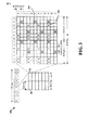
[0030]図3は、LTEにおけるDLフレーム構造の一例を示す図300である。フレーム(10ms)は、等しいサイズの10個のサブフレームに分割され得る。各サブフレームは、2つの連続するタイムスロットを含み得る。2つのタイムスロットを表すためにリソースグリッドが使用され得、各タイムスロットはリソースブロックを含む。リソースグリッドは複数のリソース要素に分割される。LTEでは、リソースブロックは、周波数領域中に12個の連続サブキャリアを含んでおり、各OFDMシンボル中のノーマルサイクリックプレフィックスについて、時間領域中に7個の連続OFDMシンボル、または84個のリソース要素を含んでいる。拡張サイクリックプレフィックスについて、リソースブロックは、時間領域中に6個の連続OFDMシンボルを含んでおり、72個のリソース要素を有する。R302、304として示されるリソース要素のいくつかは、DL基準信号(DL−RS:DL reference signal)を含む。DL−RSは、(共通RSと呼ばれることもある)セル固有RS(CRS:Cell-specific RS)302と、UE固有RS(UE−RS:UE-specific RS)304とを含む。UE−RS304は、対応する物理DL共有チャネル(PDSCH)がマッピングされるリソースブロック上のみで送信される。各リソース要素によって搬送されるビット数は変調方式に依存する。したがって、UEが受信するリソースブロックが多いほど、また変調方式が高いほど、UEのデータレートは高くなる。
[0030] FIG. 3 is a diagram 300 illustrating an example of a DL frame structure in LTE. A frame (10 ms) may be divided into 10 subframes of equal size. Each subframe may include two consecutive time slots. A resource grid may be used to represent two time slots, each time slot including a resource block. A resource grid is divided into a plurality of resource elements. In LTE, a resource block includes 12 consecutive subcarriers in the frequency domain, and for normal cyclic prefixes in each OFDM symbol, 7 consecutive OFDM symbols in the time domain, or 84 resource elements Contains. For the extended cyclic prefix, the resource block includes 6 consecutive OFDM symbols in the time domain and has 72 resource elements. Some of the resource elements indicated as
[0031]図4は、LTEにおけるULフレーム構造の一例を示す図400である。ULのための利用可能なリソースブロックは、データセクションと制御セクションとに区分され得る。制御セクションは、システム帯域幅の2つのエッジにおいて形成され得、構成可能なサイズを有し得る。制御セクション内のリソースブロックは、制御情報を送信するためにUEに割り当てられ得る。データセクションは、制御セクション中に含まれないすべてのリソースブロックを含み得る。ULフレーム構造は、データセクション中の連続するサブキャリアのすべてを単一のUEに割り当てることを可能にし得る連続サブキャリアを含むデータセクションを生じる。 [0031] FIG. 4 is a diagram 400 illustrating an example of a UL frame structure in LTE. Available resource blocks for UL may be divided into data section and control section. The control section may be formed at two edges of the system bandwidth and may have a configurable size. Resource blocks in the control section may be assigned to the UE for transmitting control information. The data section may include all resource blocks not included in the control section. The UL frame structure results in a data section that includes contiguous subcarriers that may allow all of the contiguous subcarriers in the data section to be assigned to a single UE.
[0032]UEには、eNBに制御情報を送信するために、制御セクション中のリソースブロック410a、410bが割り当てられ得る。UEには、eNBにデータを送信するために、データセクション中のリソースブロック420a、420bも割り当てられ得る。UEは、制御セクション中の割り当てられたリソースブロック上の物理UL制御チャネル(PUCCH:physical UL control channel)中で制御情報を送信し得る。UEは、データセクション中の割り当てられたリソースブロック上の物理UL共有チャネル(PUSCH:physical UL shared channel)中でデータのみまたはデータと制御情報の両方を送信し得る。UL送信は、サブフレームの両方のスロットにわたり得、周波数上でホッピングし得る。
[0032] The UE may be assigned
[0033]初期システムアクセスを実行し、物理ランダムアクセスチャネル(PRACH:physical random access channel)430中でUL同期を達成するために、リソースブロックのセットが使用され得る。PRACH430は、ランダムシーケンスを搬送し、いかなるULデータ/シグナリングも搬送することができない。各ランダムアクセスプリアンブルは、6つの連続するリソースブロックに対応する帯域幅を占有する。開始周波数はネットワークによって指定される。すなわち、ランダムアクセスプリアンブルの送信は、ある時間リソースおよび周波数リソースに制限される。周波数ホッピングはPRACHにはない。PRACH試みは単一のサブフレーム(1ms)中でまたは少数の連続サブフレームのシーケンス中で搬送され、UEは、フレーム(10ms)ごとに単一のPRACH試みだけを行うことができる。
[0033] A set of resource blocks may be used to perform initial system access and to achieve UL synchronization in physical random access channel (PRACH) 430. The
[0034]図5は、LTEにおけるユーザプレーンおよび制御プレーンのための無線プロトコルアーキテクチャの一例を示す図500である。UEおよびeNBのための無線プロトコルアーキテクチャは、レイヤ1と、レイヤ2と、レイヤ3との3つのレイヤとともに示されている。レイヤ1(L1レイヤ)は最下位レイヤであり、様々な物理レイヤ信号処理機能を実装する。L1レイヤを本明細書では物理レイヤ506と呼ぶ。レイヤ2(L2レイヤ)508は、物理レイヤ506の上にあり、物理レイヤ506を介したUEとeNBとの間のリンクを担当する。
[0034] FIG. 5 is a diagram 500 illustrating an example of a radio protocol architecture for the user plane and control plane in LTE. The radio protocol architecture for the UE and eNB is shown with three layers:
[0035]ユーザプレーンでは、L2レイヤ508は、ネットワーク側のeNBにおいて終端される、媒体アクセス制御(MAC:media access control)サブレイヤ510と、無線リンク制御(RLC:radio link control)サブレイヤ512と、パケットデータコンバージェンスプロトコル(PDCP:packet data convergence protocol)514サブレイヤとを含む。図示されていないが、UEは、ネットワーク側のPDNゲートウェイ118において終端されるネットワークレイヤ(たとえば、IPレイヤ)と、接続の他端(たとえば、ファーエンドUE、サーバなど)において終端されるアプリケーションレイヤとを含むL2レイヤ508の上にいくつかの上位レイヤを有し得る。
[0035] In the user plane, the
[0036]PDCPサブレイヤ514は、異なる無線ベアラと論理チャネルとの間で多重化を行う。PDCPサブレイヤ514はまた、無線送信オーバーヘッドを低減するために上位レイヤデータパケットのヘッダ圧縮と、データパケットを暗号化することによるセキュリティと、UEに対するeNB間のハンドオーバサポートとを与える。RLCサブレイヤ512は、上位レイヤデータパケットのセグメンテーションおよびリアセンブリと、紛失データパケットの再送信と、ハイブリッド自動再送要求(HARQ:hybrid automatic repeat request)による、順が狂った受信を補正するデータパケットの並べ替えとを行う。MACサブレイヤ510は、論理チャネルとトランスポートチャネルとの間の多重化を行う。MACサブレイヤ510はまた、UEの間で1つのセル内の様々な無線リソース(たとえば、リソースブロック)を割り振ることを担当する。MACサブレイヤ510はまたHARQ動作を担当する。
[0036] The
[0037]制御プレーンでは、UEおよびeNBのための無線プロトコルアーキテクチャは、制御プレーンのためのヘッダ圧縮機能がないことを除いて、物理レイヤ506およびL2レイヤ508について実質的に同じである。制御プレーンはまた、レイヤ3(L3レイヤ)中に無線リソース制御(RRC:radio resource control)サブレイヤ516を含む。RRCサブレイヤ516は、無線リソース(たとえば、無線ベアラ)を取得することと、eNBとUEとの間のRRCシグナリングを使用して下位レイヤを構成することとを担当する。
[0037] In the control plane, the radio protocol architecture for the UE and eNB is substantially the same for the physical layer 506 and the
[0038]図6は、アクセスネットワーク中でUE650と通信しているeNB610のブロック図である。DLでは、コアネットワークからの上位レイヤパケットが、コントローラ/プロセッサ675に与えられる。コントローラ/プロセッサ675はL2レイヤの機能を実装する。DLでは、コントローラ/プロセッサ675は、様々な優先度メトリックに基づいてヘッダ圧縮と、暗号化と、パケットのセグメンテーションおよび並べ替えと、論理チャネルとトランスポートチャネルとの間の多重化と、UE650への無線リソース割振りとを行う。コントローラ/プロセッサ675はまた、HARQ動作と、紛失パケットの再送信と、UE650へのシグナリングとを担当する。
[0038] FIG. 6 is a block diagram of an
[0039]送信(TX)プロセッサ616は、L1レイヤ(すなわち、物理レイヤ)のための様々な信号処理機能を実装する。信号処理機能は、UE650における前方誤り訂正(FEC:forward error correction)と、様々な変調方式(たとえば、2位相シフトキーイング(BPSK:binary phase-shift keying)、4位相シフトキーイング(QPSK:quadrature phase-shift keying)、M位相シフトキーイング(M−PSK:M-phase-shift keying)、多値直交振幅変調(M−QAM:M-quadrature amplitude modulation))に基づいた信号コンスタレーションへのマッピングとを可能にするために、コーディングとインターリービングとを含む。次いで、コーディングされた変調されたシンボルは並列ストリームに分割される。各ストリームは、次いでOFDMサブキャリアにマッピングされ、時間領域および/または周波数領域中で基準信号(たとえば、パイロット)と多重化され、次いで逆高速フーリエ変換(IFFT:Inverse Fast Fourier Transform)を使用して互いに合成されて、時間領域OFDMシンボルストリームを搬送する物理チャネルが生成される。OFDMストリームは、複数の空間ストリームを生成するために空間的にプリコードされる。チャネル推定器674からのチャネル推定値は、コーディングおよび変調方式を決定するために、ならびに空間処理のために使用され得る。チャネル推定値は、UE650によって送信される基準信号および/またはチャネル状態フィードバックから導出され得る。次いで、各空間ストリームは、別個の送信機618TXを介して異なるアンテナ620に与えられ得る。各送信機618TXは、送信のためにそれぞれの空間ストリームでRFキャリアを変調し得る。
[0039] A transmit (TX)
[0040]UE650において、各受信機654RXは、それのそれぞれのアンテナ652を通して信号を受信する。各受信機654RXは、RFキャリア上に変調された情報を復元し、受信機(RX)プロセッサ656に情報を与える。RXプロセッサ656は、L1レイヤの様々な信号処理機能を実装する。RXプロセッサ656は、UE650に宛てられた任意の空間ストリームを復元するために、情報に対して空間処理を実行し得る。複数の空間ストリームがUE650に宛てられた場合、それらはRXプロセッサ656によって単一のOFDMシンボルストリームに合成され得る。RXプロセッサ656は、次いで高速フーリエ変換(FFT:Fast Fourier Transform)を使用してOFDMシンボルストリームを時間領域から周波数領域に変換する。周波数領域信号は、OFDM信号のサブキャリアごとに別々のOFDMシンボルストリームを備える。各サブキャリア上のシンボルと、基準信号とは、eNB610によって送信される、可能性が最も高い信号コンスタレーションポイントを決定することによって復元され、復調される。これらの軟判定は、チャネル推定器658によって計算されるチャネル推定値に基づき得る。軟判定は、次いで、物理チャネル上でeNB610によって最初に送信されたデータと制御信号とを復元するために復号され、デインターリーブされる。データおよび制御信号は、次いで、コントローラ/プロセッサ659に与えられる。
At
[0041]コントローラ/プロセッサ659はL2レイヤを実装する。コントローラ/プロセッサは、プログラムコードとデータとを記憶するメモリ660に関連付けられ得る。メモリ660はコンピュータ可読媒体と呼ばれることがある。ULでは、コントローラ/プロセッサ659は、コアネットワークからの上位レイヤパケットを復元するために、トランスポートチャネルと論理チャネルとの間の多重分離と、パケットリアセンブリと、復号(decipher)と、ヘッダ復元(decompression)と、制御信号処理とを行う。上位レイヤパケットは、次いで、L2レイヤの上のすべてのプロトコルレイヤを表すデータシンク662に与えられる。また、様々な制御信号がL3処理のためにデータシンク662に与えられ得る。コントローラ/プロセッサ659はまた、HARQ動作をサポートするために肯定応答(ACK)および/または否定応答(NACK)プロトコルを使用した誤り検出を担当する。
The controller /
[0042]ULでは、データソース667は、コントローラ/プロセッサ659に上位レイヤパケットを与えるために使用される。データソース667は、L2レイヤの上のすべてのプロトコルレイヤを表す。eNB610によるDL送信に関して説明した機能と同様に、コントローラ/プロセッサ659は、ヘッダ圧縮と、暗号化と、パケットのセグメンテーションおよび並べ替えと、eNB610による無線リソース割振りに基づく論理チャネルとトランスポートチャネルとの間の多重化とを行うことによって、ユーザプレーンおよび制御プレーンのためのL2レイヤを実装する。コントローラ/プロセッサ659はまた、HARQ動作、紛失パケットの再送信、およびeNB610へのシグナリングを担当する。
[0042] In UL,
[0043]eNB610によって送信される基準信号またはフィードバックからの、チャネル推定器658によって導出されるチャネル推定値は、適切なコーディングおよび変調方式を選択することと、空間処理を可能にすることとを行うために、TXプロセッサ668によって使用され得る。TXプロセッサ668によって生成される空間ストリームは、別個の送信機654TXを介して異なるアンテナ652に与えられ得る。各送信機654TXは、送信のためにそれぞれの空間ストリームでRFキャリアを変調し得る。
[0043] Channel estimates derived by
[0044]UL送信は、UE650における受信機機能に関して説明した方法と同様の方法でeNB610において処理される。各受信機618RXは、それのそれぞれのアンテナ620を通して信号を受信する。各受信機618RXは、RFキャリア上で変調された情報を復元し、RXプロセッサ670に情報を与える。RXプロセッサ670はL1レイヤを実装し得る。
[0044] UL transmissions are processed at
[0045]コントローラ/プロセッサ675はL2レイヤを実装する。コントローラ/プロセッサ675は、プログラムコードとデータとを記憶するメモリ676に関連付けられ得る。メモリ676はコンピュータ可読媒体と呼ばれることがある。ULでは、コントローラ/プロセッサ675は、UE650からの上位レイヤパケットを復元するために、トランスポートチャネルと論理チャネルとの間の多重分離と、パケットリアセンブリと、復号と、ヘッダ復元と、制御信号処理とを行う。コントローラ/プロセッサ675からの上位レイヤパケットはコアネットワークに与えられ得る。コントローラ/プロセッサ675はまた、HARQ動作をサポートするためにACKおよび/またはNACKプロトコルを使用した誤り検出を担当する。
The controller /
[0046]図7はデバイス間通信システム700の図である。デバイス間(D2D)通信システム700は、複数のワイヤレスデバイス704、706、708、710を含む。デバイス間通信システム700は、たとえば、ワイヤレスワイドエリアネットワーク(WWAN:wireless wide area network)などのセルラー通信システムと重なり得る。ワイヤレスデバイス704、706、708、710の一部は、DL/UL WWANスペクトルを使用してデバイス間通信において互いに通信し、一部は基地局702と通信し、一部は両方を行い得る。たとえば、図7に示されているように、ワイヤレスデバイス708、710はデバイス間通信中であり、ワイヤレスデバイス704、706はデバイス間通信中である。ワイヤレスデバイス704、706は基地局702とも通信している。
[0046] FIG. 7 is a diagram of an
[0047]以下で説明する例示的な方法および装置は、たとえば、FlashLinQ、WiMedia、Bluetooth(登録商標)、ZigBee(登録商標)、またはIEEE802.11規格に基づくWi−Fiに基づくワイヤレスデバイス間通信システムなど、様々なワイヤレスデバイス間通信システムのいずれにも適用可能である。説明を簡略化するために、例示的な方法および装置についてLTEのコンテキスト内で説明する。ただし、例示的な方法および装置は、様々な他のワイヤレスデバイス間通信システムにより一般的に適用可能であることを当業者は理解されよう。 [0047] The exemplary methods and apparatus described below are wireless inter-device communication systems based on, for example, FlashLinQ, WiMedia, Bluetooth®, ZigBee®, or Wi-Fi based on the IEEE 802.11 standard. And so on, any of various wireless inter-device communication systems. To simplify the description, exemplary methods and apparatus are described within the context of LTE. Those skilled in the art will appreciate, however, that the exemplary methods and apparatus are generally applicable to various other wireless inter-device communication systems.
[0048]本開示の一態様は、公共安全上の懸念によって動機づけられたブロードキャストD2D通信に関する。ブロードキャスト通信のためのベースライン設計は、帯域幅を狭帯域サブチャネルに分割するものであり得、ここにおいて、いくつかの近接送信機(neighboring transmitters)の各送信機は、信号を送信するために1つのサブチャネルを選択し得る。サブチャネル選択は、受信されたエネルギー測定値に基づき得る。 [0048] One aspect of the present disclosure relates to broadcast D2D communication motivated by public security concerns. A baseline design for broadcast communication may be to divide bandwidth into narrowband subchannels, where each transmitter of several neighboring transmitters to transmit signals. One subchannel may be selected. Subchannel selection may be based on the received energy measurements.
[0049]インバンドエミッションによってシステム性能に対する制限が課され得る。インバンドエミッション(IBE)は、あるサブチャネル上で送信するある送信機によって引き起こされ、別のサブチャネル上で受信機に送信する別の送信機に課される、干渉である。本開示では、帯域幅のサブチャネル上のIBEを認識しながらのサブチャネル選択を可能にすることによってシステム性能を改善するための方法および装置が提供される。 [0049] Limitations on system performance may be imposed by in-band emissions. In-band emission (IBE) is interference that is caused by one transmitter transmitting on one subchannel and imposed on another transmitter transmitting to a receiver on another subchannel. In the present disclosure, methods and apparatus are provided to improve system performance by enabling subchannel selection while recognizing IBE on bandwidth subchannels.
[0050]図8は、インバンドエミッションモデルを示す図800である。図9は、送信機によってもたらされるアウテージエリア(たとえば、ゾーン、領域など)を示す図900である。サブチャネル選択アルゴリズムを決定するために2つの観測が利用され得る。第1に、すべてのサブチャネルが同じ量の干渉を受けるとは限らない。図8を参照すると、インバンドエミッションモデルのプロットは、近接サブチャネルならびに他のサブチャネル(たとえば、I/Qまたは画像サブチャネル)がより多くの干渉を経験することを示す。 [0050] FIG. 8 is a diagram 800 illustrating an in-band emission model. FIG. 9 is a diagram 900 illustrating outage areas (eg, zones, regions, etc.) provided by a transmitter. Two observations may be utilized to determine the subchannel selection algorithm. First, not all subchannels receive the same amount of interference. Referring to FIG. 8, a plot of the in-band emission model shows that the near subchannel as well as the other subchannels (eg, I / Q or image subchannels) experience more interference.
[0051]第2に、より遠く離れて位置する送信機がより多くの干渉を引き起こす。たとえば、指数4および−30dBcのIBEを用いた均一な経路損失をもつ単純なモデルを考える。図9を参照すると、送信機TX1 902は、近接送信機TX2 904から距離dである。送信機TX1 902はまた、別の近接送信機TX3 906からdよりも大きい距離にある。送信機TX2 904のアウテージゾーン914および送信機TX3 906のアウテージゾーン916も示される。アウテージゾーンは、ホーム送信機(たとえば、TX1 902)からの信号の意図された受信機がしきい値(たとえば、0dB)よりも小さい信号対干渉プラス雑音比(SINR:signal-to-interference-plus-noise ratio)を経験する、近接送信機(たとえば、TX2 904またはTX3 906)に関係する地理的エリア(領域)として定義され得る。
[0051] Second, transmitters located farther away cause more interference. For example, consider a simple model with uniform path loss using IBE with
[0052]図9において、送信機TX1 902から距離dにある送信機TX2 904は、約d/10の半径を有する円形アウテージゾーン914をもたらし得る。送信機TX2 904に10倍近接した、送信機TX1 902からの信号の意図された受信機は、送信機TX2 904のIBEによる送信機TX2 904のアウテージゾーン914中にあることになる。したがって、送信機TX1 902からの信号の意図された受信機は、送信機TX2 904のアウテージゾーン914中にあるとき、しきい値(たとえば、0dB)よりも小さいSINRを経験することになる。送信機がもたらすアウテージエリアによって送信機が特徴づけられる場合、送信機TX1 902からより遠い送信機(たとえば、dよりも大きい距離にある送信機TX3 906)は、送信機により近い送信機(たとえば、送信機TX2 904)よりも大きいアウテージゾーンをもたらすことになる。
[0052] In FIG. 9,
[0053]一態様では、サブチャネル選択のための方法が提供される。一例によれば、いくつかの近接送信機の各送信機は、それの周囲をモニターし、所与の帯域幅のどのサブチャネルが近接送信機によって占有されるかを決定し得る。各送信機はまた、各近接送信機の相対強度をモニターし得る。 [0053] In one aspect, a method is provided for subchannel selection. According to an example, each transmitter of some proximity transmitters may monitor its surroundings to determine which subchannels of a given bandwidth are occupied by the proximity transmitters. Each transmitter may also monitor the relative strength of each proximity transmitter.
[0054]各サブチャネルについて、送信機は、送信機が、意図された受信機に信号を送信するためのそれぞれのサブチャネルを使用しようとする場合に、それぞれのサブチャネルに関係するアウテージゾーン(アウテージ領域)を推定し得る。推定は、モデル(たとえば、図8に示されたパターン)に基づくIBEの推定、および/またはそれぞれのサブチャネル上で送信する近接送信機までの経路損失推定に基づくアウテージゾーンの推定を含み得る。推定中に、1)より大きいIBEをもつサブチャネルが、より大きいアウテージゾーンを暗示し、2)より弱い送信機が、より大きいアウテージゾーンを暗示するという特性が適用され得る。送信機は次いで、最も小さい推定されたアウテージゾーンをもつサブチャネルを選択し得る。 [0054] For each subchannel, if the transmitter attempts to use the respective subchannel to transmit the signal to the intended receiver, the outage zone associated with the respective subchannel (Outage region) can be estimated. The estimation may include estimation of IBE based on a model (e.g., the pattern shown in FIG. 8) and / or estimation of outage zones based on path loss estimation to adjacent transmitters transmitting on each subchannel . During estimation, the characteristics may be applied that 1) subchannels with IBE larger imply a larger outage zone and 2) weaker transmitters imply a larger outage zone. The transmitter may then select the subchannel with the smallest estimated outage zone.
[0055]図10は、ワイヤレス通信の方法のフローチャート1000である。この方法は、第1の送信機(たとえば、UEまたは図7のワイヤレスデバイス704、706、708、または710のうちのいずれか1つ)によって実行され得る。
[0055] FIG. 10 is a
[0056]ステップ1002において、第1の送信機は、帯域幅中の複数のサブチャネル上でそれぞれ送信する複数の近接送信機の各々の送信電力を決定する。送信電力決定は、それぞれのサブチャネル上で送信する近接送信機のインバンドエミッション(IBE)電力を決定すること、および/または意図された送信信号を送信する近接送信機の送信電力を決定することを含み得る。一態様では、複数のサブチャネル上でそれぞれ送信する複数の近接送信機の各々についてのIBE電力は、IBEのモデルと、それぞれのサブチャネル上の意図された送信信号の送信電力の決定とに基づいて決定される。
[0056] At
[0057]ステップ1004において、第1の送信機は、複数のサブチャネル上でそれぞれ送信する複数の近接送信機の各々までの経路損失を検出する。第1の送信機は、次いで、複数のサブチャネルの各々上の決定された送信電力と、複数のサブチャネル上でそれぞれ送信する複数の近接送信機の各々までの検出された経路損失とに基づいて、信号を送信するための複数のサブチャネルのうちの1つを選択し得る。
[0057] At
[0058]たとえば、ステップ1006において、複数のサブチャネルの各々について、第1の送信機は、サブチャネル上で送信する近接送信機の決定された送信電力と、近接送信機までの検出された経路損失とに基づいて、サブチャネルについてのアウテージ領域のサイズを推定する。アウテージ領域は、第1の送信機からの信号の意図された受信機がしきい値(たとえば、0dB)よりも小さい信号対干渉プラス雑音比(SINR)を経験する地理的エリアを含み得る。一態様では、サブチャネル上で送信する近接送信機の決定された送信電力は、サブチャネルについてのアウテージ領域のサイズを示す。さらに、サブチャネル上で送信する近接送信機までの検出された経路損失も、サブチャネルについてのアウテージ領域のサイズを示す。 [0058] For example, at step 1006, for each of the plurality of subchannels, the first transmitter transmits the determined transmission power of the proximity transmitter transmitting on the subchannel and the detected path to the proximity transmitter. Based on the loss, estimate the size of the outage region for the subchannel. The outage region may include the geographic area where the intended receiver of the signal from the first transmitter experiences a signal to interference plus noise ratio (SINR) that is less than a threshold (e.g., 0 dB). In one aspect, the determined transmit power of the proximity transmitter transmitting on the subchannel indicates the size of the outage region for the subchannel. Furthermore, the detected path loss to the close transmitter transmitting on the subchannel also indicates the size of the outage region for the subchannel.
[0059]ステップ1008において、第1の送信機は、複数のサブチャネルの各々についての推定されたアウテージ領域サイズに基づいて複数のサブチャネルのうちの1つを選択する。一態様では、第1の送信機は、最も小さい推定されたアウテージ領域サイズを有するサブチャネルに基づいて複数のサブチャネルのうちの1つを選択する。
[0059] At
[0060]図11は、例示的な装置1102の異なるモジュール/手段/構成要素間のデータフローを示す概念データフロー図1100である。本装置は、第1の送信機(たとえば、UEまたは図7のワイヤレスデバイス704、706、708、または710のうちのいずれか1つ)であり得る。本装置は、受信モジュール1104と、送信電力決定モジュール1106と、経路損失検出モジュール1108と、アウテージ領域推定モジュール1110と、サブチャネル処理モジュール1112と、送信モジュール1114とを含む。
[0060] FIG. 11 is a conceptual data flow diagram 1100 illustrating data flow between different modules / means / components of the
[0061]送信電力決定モジュール1106は、帯域幅中の複数のサブチャネル上でそれぞれ送信する複数の近接送信機(たとえば、1つまたは複数の近接送信機1150)の各々の送信電力を(受信モジュール1104および送信モジュール1114を介して)決定する。送信電力決定は、それぞれのサブチャネル上で送信する近接送信機のインバンドエミッション(IBE)電力を決定すること、および/または意図された送信信号を送信する近接送信機の送信電力を決定することを含み得る。一態様では、複数のサブチャネル上でそれぞれ送信する複数の近接送信機の各々についてのIBE電力が、IBEのモデルと、それぞれのサブチャネル上の意図された送信信号の送信電力の決定とに基づいて決定される。
[0061] The transmit
[0062]経路損失検出モジュール1108は、複数のサブチャネル上でそれぞれ送信する複数の近接送信機の各々までの経路損失を(受信モジュール1104および送信モジュール1114を介して)検出する。装置1102は、複数のサブチャネルの各々上の決定された送信電力と、複数のサブチャネル上でそれぞれ送信する複数の近接送信機の各々までの検出された経路損失とに基づいて、(送信モジュール1114を介して)信号を送信するための複数のサブチャネルのうちの1つを選択し得る。
Path
[0063]たとえば、複数のサブチャネルの各々について、アウテージ領域推定モジュール1110は、サブチャネル上で送信する近接送信機の決定された送信電力と、近接送信機までの検出された経路損失とに基づいて、サブチャネルについてのアウテージ領域のサイズを推定する。アウテージ領域は、第1の送信機からの信号の意図された受信機が、しきい値(たとえば、0dB)よりも小さい信号対干渉プラス雑音比(SINR)を経験する地理的エリアを含み得る。一態様では、サブチャネル上で送信する近接送信機の決定された送信電力は、サブチャネルについてのアウテージ領域のサイズを示す。さらに、サブチャネル上で送信する近接送信機までの検出された経路損失も、サブチャネルについてのアウテージ領域のサイズを示す。
[0063] For example, for each of a plurality of subchannels, outage
[0064]サブチャネル処理モジュール1112は、複数のサブチャネルの各々についての推定されたアウテージ領域サイズに基づいて複数のサブチャネルのうちの1つを選択する。一態様では、サブチャネル処理モジュール1112は、最も小さい推定されたアウテージ領域サイズを有するサブチャネルに基づいて複数のサブチャネルのうちの1つを選択する。
[0065]本装置は、図10の上述のフローチャート中のアルゴリズムのステップの各々を実行する追加のモジュールを含み得る。したがって、図10の上述のフローチャート中の各ステップは1つのモジュールによって実行され得、本装置は、それらのモジュールのうちの1つまたは複数を含み得る。それらのモジュールは、述べられたプロセス/アルゴリズムを行うように特に構成された1つまたは複数のハードウェア構成要素であるか、述べられたプロセス/アルゴリズムを実行するように構成されたプロセッサによって実装されるか、プロセッサによる実装のためにコンピュータ可読媒体内に記憶されるか、またはそれらの何らかの組合せであり得る。 The apparatus may include additional modules that perform each of the steps of the algorithm in the above-described flowchart of FIG. Thus, each step in the above-described flow chart of FIG. 10 may be performed by one module, and the apparatus may include one or more of those modules. The modules may be one or more hardware components specifically configured to perform the described process / algorithm, or implemented by a processor configured to execute the described process / algorithm Or stored in computer readable media for implementation by a processor, or some combination thereof.
[0066]図12は、処理システム1214を採用する装置1102’のためのハードウェア実装形態の一例を示す図1200である。処理システム1214は、バス1224によって概略的に表されるバスアーキテクチャを用いて実装され得る。バス1224は、処理システム1214の特定の適用例および全体的な設計制約に応じて、任意の数の相互接続バスおよびブリッジを含み得る。バス1224は、プロセッサ1204によって表される1つまたは複数のプロセッサおよび/またはハードウェアモジュールと、モジュール1104、1106、1108、1110、1112、1114と、コンピュータ可読媒体/メモリ1206とを含む様々な回路を互いにリンクする。バス1224はまた、タイミングソース、周辺機器、電圧調整器、および電力管理回路など、様々な他の回路をリンクし得るが、これらの回路は当技術分野においてよく知られており、したがって、これ以上説明しない。
[0066] Figure 12 is a drawing 1200 illustrating an example of a hardware implementation for an apparatus 1102 'that employs a
[0067]処理システム1214はトランシーバ1210に結合され得る。トランシーバ1210は1つまたは複数のアンテナ1220に結合される。トランシーバ1210は、伝送媒体を介して様々な他の装置と通信するための手段を与える。トランシーバ1210は、1つまたは複数のアンテナ1220から信号を受信し、受信された信号から情報を抽出し、抽出された情報を処理システム1214、特に受信モジュール1104に与える。さらに、トランシーバ1210は、処理システム1214、特に送信モジュール1114から情報を受信し、受信された情報に基づいて、1つまたは複数のアンテナ1220に適用されるべき信号を生成する。処理システム1214は、コンピュータ可読媒体/メモリ1206に結合されたプロセッサ1204を含む。プロセッサ1204は、コンピュータ可読媒体/メモリ1206に記憶されたソフトウェアの実行を含む一般的な処理を担当する。ソフトウェアは、プロセッサ1204によって実行されたとき、処理システム1214に、特定の装置のための上記で説明した様々な機能を実行させる。コンピュータ可読媒体/メモリ1206はまた、ソフトウェアを実行するときにプロセッサ1204によって操作されるデータを記憶するために使用され得る。処理システムは、モジュール1104、1106、1108、1110、1112、および1114のうちの少なくとも1つをさらに含む。それらのモジュールは、プロセッサ1204中で動作するか、コンピュータ可読媒体/メモリ1206中に常駐する/記憶されたソフトウェアモジュールであるか、プロセッサ1204に結合された1つまたは複数のハードウェアモジュールであるか、またはそれらの何らかの組合せであり得る。処理システム1214は、UE650の構成要素であり得、メモリ660および/またはTXプロセッサ668と、RXプロセッサ656と、コントローラ/プロセッサ659とのうちの少なくとも1つを含み得る。
[0068]一構成では、ワイヤレス通信のための装置1102/1102’は、帯域幅中の複数のサブチャネル上でそれぞれ送信する複数の近接送信機の各々の送信電力を決定するための手段と、複数のサブチャネル上でそれぞれ送信する複数の近接送信機の各々までの経路損失を検出するための手段と、複数のサブチャネルの各々上の決定された送信電力と、複数のサブチャネル上でそれぞれ送信する複数の近接送信機の各々までの検出された経路損失とに基づいて、信号を送信するための複数のサブチャネルのうちの1つを選択するための手段と、サブチャネル上で送信する近接送信機の決定された送信電力と、近接送信機までの検出された経路損失とに基づいて、サブチャネルについてのアウテージ領域のサイズを推定するための手段とを含み、ここにおいて、選択するための手段は、複数のサブチャネルの各々についての推定されたアウテージ領域サイズに基づいて複数のサブチャネルのうちの1つを選択するように構成される。
[0068] In one configuration, an
[0069]上述の手段は、上述の手段によって具陳された機能を実行するように構成された、装置1102、および/または装置1102’の処理システム1214の上述のモジュールのうちの1つまたは複数であり得る。上記で説明したように、処理システム1214は、TXプロセッサ668と、RXプロセッサ656と、コントローラ/プロセッサ659とを含み得る。したがって、一構成では、上述の手段は、上述の手段によって具陳される機能を実行するように構成された、TXプロセッサ668と、RXプロセッサ656と、コントローラ/プロセッサ659とであり得る。
[0069] The means described above are configured to perform the functions recited by the means described above, and / or one or more of the aforementioned modules of the
[0070]開示したプロセスにおけるステップの特定の順序または階層は、例示的な手法の一例であることを理解されたい。設計上の選好に基づいて、プロセスにおけるステップの特定の順序または階層は並べ替えられ得ることを理解されたい。さらに、いくつかのステップは組み合わされるかまたは省略され得る。添付の方法クレームは、様々なステップの要素を例示的な順序で提示したものであり、提示された特定の順序または階層に限定されるものではない。 It should be understood that the specific order or hierarchy of steps in the processes disclosed is an example of exemplary approaches. It should be understood that based on design preferences, the particular order or hierarchy of steps in the process may be rearranged. Furthermore, some steps may be combined or omitted. The accompanying method claims present elements of the various steps in a sample order, and are not limited to the specific order or hierarchy presented.
[0071]以上の説明は、当業者が本明細書で説明された様々な態様を実行できるようにするために提供される。これらの態様に対する様々な変更は当業者には容易に明らかであり、本明細書で定義した一般的原理は他の態様に適用され得る。したがって、特許請求の範囲は、本明細書に示された態様に限定されるものではなく、特許請求の言い回しに矛盾しない全範囲を与えられるべきであり、単数形の要素への言及は、そのように明記されていない限り、「唯一無二の」を意味するものではなく、「1つまたは複数の」を意味するものである。「例示的」という単語は、本明細書では「例、事例、または例示の働きをすること」を意味するために使用する。「例示的」として本明細書で説明するいかなる態様も、必ずしも他の態様よりも好適または有利なものと解釈すべきではない。別段に明記されていない限り、「いくつかの」という語は「1つまたは複数の」を表す。「A、B、またはCのうちの少なくとも1つ」、「A、B、およびCのうちの少なくとも1つ」、ならびに「A、B、C、またはそれらの任意の組合せ」などの組合せは、A、B、および/またはCの任意の組合せを含み、Aのうちの複数個、Bのうちの複数個、またはCのうちの複数個を含み得る。詳細には、「A、B、またはCのうちの少なくとも1つ」、「A、B、およびCのうちの少なくとも1つ」、および「A、B、C、またはそれらの任意の組合せ」などの組合せは、Aのみ、Bのみ、Cのみ、AおよびB、AおよびC、BおよびC、またはAおよびBおよびCであり得、ただし、いずれのそのような組合せも、A、B、またはCのうちの1つまたは複数のメンバーを含み得る。当業者に知られている、または後に知られることになる、本開示全体にわたって説明された様々な態様の要素のすべての構造的および機能的均等物は、参照により本明細書に明確に組み込まれ、特許請求の範囲に包含されるものである。さらに、本明細書で開示されたいかなることも、そのような開示が特許請求の範囲に明示的に具陳されているかどうかにかかわらず、公に供するものではない。いかなるクレーム要素も、その要素が「ための手段」という語句を使用して明確に具陳されていない限り、ミーンズプラスファンクションとして解釈されるべきではない。
以下に、本願出願の当初の特許請求の範囲に記載された発明を付記する。
[C1]
第1の送信機のワイヤレス通信の方法であって、
帯域幅中の複数のサブチャネル上でそれぞれ送信する複数の近接送信機の各々の送信電力を決定することと、
前記複数のサブチャネル上でそれぞれ送信する前記複数の近接送信機の各々までの経路損失を検出することと、
前記複数のサブチャネルの各々上の前記決定された送信電力と、前記複数のサブチャネル上でそれぞれ送信する前記複数の近接送信機の各々までの前記検出された経路損失とに基づいて、信号を送信するための前記複数のサブチャネルのうちの1つを選択することと
を備える方法。
[C2]
前記送信電力を前記決定することは、
インバンドエミッション(IBE)電力、または
意図された送信信号の送信電力
のうちの少なくとも1つを決定することを備える、C1に記載の方法。
[C3]
前記複数のサブチャネル上でそれぞれ送信する前記複数の近接送信機の各々についての前記IBE電力は、IBEのモデルと、それぞれのサブチャネル上の前記意図された送信信号の前記送信電力の決定とに基づいて決定される、C2に記載の方法。
[C4]
前記複数のサブチャネルの各々について、サブチャネル上で送信する近接送信機の決定された送信電力と、前記近接送信機までの前記検出された経路損失とに基づいて、前記サブチャネルについてのアウテージ領域のサイズを推定することをさらに備え、
ここにおいて、前記複数のサブチャネルのうちの前記1つは、前記複数のサブチャネルの各々についての前記推定されたアウテージ領域サイズに基づいて選択される、C1に記載の方法。
[C5]
前記複数のサブチャネルのうちの前記1つは、最も小さい推定されたアウテージ領域サイズを有する前記サブチャネルに基づいて選択される、C4に記載の方法。
[C6]
前記アウテージ領域は、前記第1の送信機からの前記信号の意図された受信機がしきい値よりも小さい信号対干渉プラス雑音比(SINR)を経験する地理的エリアを備える、C4に記載の方法。
[C7]
前記サブチャネル上で送信する前記近接送信機の前記決定された送信電力は、前記サブチャネルについての前記アウテージ領域の前記サイズを示す、C4に記載の方法。
[C8]
前記サブチャネル上で送信する前記近接送信機までの前記検出された経路損失は、前記サブチャネルについての前記アウテージ領域の前記サイズを示す、C4に記載の方法。
[C9]
ワイヤレス通信のための第1の送信機であって、
帯域幅中の複数のサブチャネル上でそれぞれ送信する複数の近接送信機の各々の送信電力を決定するための手段と、
前記複数のサブチャネル上でそれぞれ送信する前記複数の近接送信機の各々までの経路損失を検出するための手段と、
前記複数のサブチャネルの各々上の前記決定された送信電力と、前記複数のサブチャネル上でそれぞれ送信する前記複数の近接送信機の各々までの前記検出された経路損失とに基づいて、信号を送信するための前記複数のサブチャネルのうちの1つを選択するための手段と
を備える第1の送信機。
[C10]
前記送信電力を決定するための前記手段は、
インバンドエミッション(IBE)電力、または
意図された送信信号の送信電力
のうちの少なくとも1つを決定するように構成される、C9に記載の第1の送信機。
[C11]
前記複数のサブチャネル上でそれぞれ送信する前記複数の近接送信機の各々についての前記IBE電力は、IBEのモデルと、それぞれのサブチャネル上の前記意図された送信信号の前記送信電力の決定とに基づいて決定される、C10に記載の第1の送信機。
[C12]
前記複数のサブチャネルの各々について、サブチャネル上で送信する近接送信機の決定された送信電力と、前記近接送信機までの前記検出された経路損失とに基づいて、前記サブチャネルについてのアウテージ領域のサイズを推定するための手段をさらに備え、
ここにおいて、選択するための前記手段は、前記複数のサブチャネルの各々についての前記推定されたアウテージ領域サイズに基づいて前記複数のサブチャネルのうちの前記1つを選択するように構成される、C9に記載の第1の送信機。
[C13]
選択するための前記手段は、最も小さい推定されたアウテージ領域サイズを有する前記サブチャネルに基づいて前記複数のサブチャネルのうちの前記1つを選択するように構成される、C12に記載の第1の送信機。
[C14]
前記アウテージ領域は、前記第1の送信機からの前記信号の意図された受信機がしきい値よりも小さい信号対干渉プラス雑音比(SINR)を経験する地理的エリアを備える、C12に記載の第1の送信機。
[C15]
前記サブチャネル上で送信する前記近接送信機の前記決定された送信電力は、前記サブチャネルについての前記アウテージ領域の前記サイズを示す、C12に記載の第1の送信機。
[C16]
前記サブチャネル上で送信する前記近接送信機までの前記検出された経路損失は、前記サブチャネルについての前記アウテージ領域の前記サイズを示す、C12に記載の第1の送信機。
[C17]
ワイヤレス通信のための第1の送信機であって、
メモリと、
前記メモリに結合され、
帯域幅中の複数のサブチャネル上でそれぞれ送信する複数の近接送信機の各々の送信電力を決定することと、
前記複数のサブチャネル上でそれぞれ送信する前記複数の近接送信機の各々までの経路損失を検出することと、
前記複数のサブチャネルの各々上の前記決定された送信電力と、前記複数のサブチャネル上でそれぞれ送信する前記複数の近接送信機の各々までの前記検出された経路損失とに基づいて、信号を送信するための前記複数のサブチャネルのうちの1つを選択することと
を行うように構成された少なくとも1つのプロセッサと、
を備える第1の送信機。
[C18]
前記送信電力を決定するように構成された前記少なくとも1つのプロセッサは、
インバンドエミッション(IBE)電力、または
意図された送信信号の送信電力
のうちの少なくとも1つを決定するように構成され、
ここにおいて、前記複数のサブチャネル上でそれぞれ送信する前記複数の近接送信機の各々についての前記IBE電力は、IBEのモデルと、それぞれのサブチャネル上の前記意図された送信信号の前記送信電力の決定とに基づいて決定される、C17に記載の第1の送信機。
[C19]
前記少なくとも1つのプロセッサは、
前記複数のサブチャネルの各々について、サブチャネル上で送信する近接送信機の決定された送信電力と、前記近接送信機までの前記検出された経路損失とに基づいて、前記サブチャネルについてのアウテージ領域のサイズを推定するようにさらに構成され、
ここにおいて、前記少なくとも1つのプロセッサは、前記複数のサブチャネルの各々についての前記推定されたアウテージ領域サイズに基づいて前記複数のサブチャネルのうちの前記1つを選択するように構成される、C17に記載の第1の送信機。
[C20]
前記少なくとも1つのプロセッサは、最も小さい推定されたアウテージ領域サイズを有する前記サブチャネルに基づいて前記複数のサブチャネルのうちの前記1つを選択するように構成される、C19に記載の第1の送信機。
[C21]
前記アウテージ領域は、前記第1の送信機からの前記信号の意図された受信機がしきい値よりも小さい信号対干渉プラス雑音比(SINR)を経験する地理的エリアを備える、C19に記載の第1の送信機。
[C22]
前記サブチャネル上で送信する前記近接送信機の前記決定された送信電力は、前記サブチャネルについての前記アウテージ領域の前記サイズを示す、C19に記載の第1の送信機。
[C23]
前記サブチャネル上で送信する前記近接送信機までの前記検出された経路損失は、前記サブチャネルについての前記アウテージ領域の前記サイズを示す、C19に記載の第1の送信機。
[C24]
コンピュータ可読媒体に記憶されたコンピュータプログラム製品であって、少なくとも1つのプロセッサ上で実行されたとき、前記少なくとも1つのプロセッサに、
帯域幅中の複数のサブチャネル上でそれぞれ送信する複数の近接送信機の各々の送信電力を決定することと、
前記複数のサブチャネル上でそれぞれ送信する前記複数の近接送信機の各々までの経路損失を検出することと、
前記複数のサブチャネルの各々上の前記決定された送信電力と、前記複数のサブチャネル上でそれぞれ送信する前記複数の近接送信機の各々までの前記検出された経路損失とに基づいて、信号を送信するための前記複数のサブチャネルのうちの1つを選択することと
を行わせるコードを備えるコンピュータプログラム製品。
[C25]
前記少なくとも1つのプロセッサに前記送信電力を決定させる前記コードは、
インバンドエミッション(IBE)電力、または
意図された送信信号の送信電力
のうちの少なくとも1つを決定するように構成され、
ここにおいて、前記複数のサブチャネル上でそれぞれ送信する前記複数の近接送信機の各々についての前記IBE電力は、IBEのモデルと、それぞれのサブチャネル上の前記意図された送信信号の前記送信電力の決定とに基づいて決定される、C24に記載のコンピュータプログラム製品。
[C26]
前記複数のサブチャネルの各々について、前記少なくとも1つのプロセッサに、サブチャネル上で送信する近接送信機の決定された送信電力と、前記近接送信機までの前記検出された経路損失とに基づいて、前記サブチャネルについてのアウテージ領域のサイズを推定させるコードをさらに備え、
ここにおいて、前記少なくとも1つのプロセッサに選択させる前記コードは、前記複数のサブチャネルの各々についての前記推定されたアウテージ領域サイズに基づいて前記複数のサブチャネルのうちの前記1つを選択するように構成される、C24に記載のコンピュータプログラム製品。
[C27]
前記少なくともプロセッサに選択させる前記コードは、最も小さい推定されたアウテージ領域サイズを有する前記サブチャネルに基づいて前記複数のサブチャネルのうちの前記1つを選択するように構成される、C26に記載のコンピュータプログラム製品。
[C28]
前記アウテージ領域は、前記第1の送信機からの前記信号の意図された受信機がしきい値よりも小さい信号対干渉プラス雑音比(SINR)を経験する地理的エリアを備える、C26に記載のコンピュータプログラム製品。
[C29]
前記サブチャネル上で送信する前記近接送信機の前記決定された送信電力は、前記サブチャネルについての前記アウテージ領域の前記サイズを示す、C26に記載のコンピュータプログラム製品。
[C30]
前記サブチャネル上で送信する前記近接送信機までの前記検出された経路損失は、前記サブチャネルについての前記アウテージ領域の前記サイズを示す、C26に記載のコンピュータプログラム製品。
[0071] The previous description is provided to enable any person skilled in the art to practice the various aspects described herein. Various modifications to these aspects will be readily apparent to those skilled in the art, and the general principles defined herein may be applied to other aspects. Accordingly, the claims should not be limited to the embodiments set forth herein, but should be given the full scope consistent with the wording of the claims, and references to singular elements shall Unless specifically stated as such, it does not mean "one or two", but means "one or more". The word "exemplary" is used herein to mean "serving as an example, instance, or illustration." Any aspect described herein as "exemplary" is not necessarily to be construed as preferred or advantageous over other aspects. The term "some" refers to "one or more" unless specifically stated otherwise. A combination such as “at least one of A, B, or C”, “at least one of A, B, and C”, and “A, B, C, or any combination thereof” is It may include any combination of A, B, and / or C, and may include more than one of A, more than one of B, or more than one of C. Specifically, "at least one of A, B, or C", "at least one of A, B, and C", and "A, B, C, or any combination thereof" or the like. The combination of A may be A only, B only, C only, A and B, A and C, B and C, or A and B and C, with the proviso that any such combination is A, B or It may include one or more members of C. All structural and functional equivalents of the elements of the various embodiments described throughout the disclosure, which will be known to or known to those skilled in the art, are specifically incorporated herein by reference. , Which is included in the scope of the claims. Furthermore, nothing disclosed herein is publicly available, regardless of whether such disclosure is explicitly recited in the claims. No claim element should be construed as means-plus-function unless the element is specifically recited using the phrase "means for."
In the following, the invention described in the original claims of the present application is appended.
[C1]
A method of wireless communication of a first transmitter, comprising:
Determining the transmit power of each of a plurality of close proximity transmitters transmitting respectively on a plurality of subchannels in the bandwidth;
Detecting path loss to each of the plurality of close proximity transmitters transmitting respectively on the plurality of subchannels;
A signal is determined based on the determined transmission power on each of the plurality of subchannels and the detected path loss to each of the plurality of adjacent transmitters transmitting respectively on the plurality of subchannels. Selecting one of the plurality of subchannels for transmission
How to provide.
[C2]
The determining of the transmission power is
In-band emission (IBE) power, or
Transmission power of the intended transmission signal
The method according to C1, comprising determining at least one of
[C3]
The IBE power for each of the plurality of proximity transmitters transmitting on the plurality of subchannels, respectively, may be a model of IBE and a determination of the transmission power of the intended transmission signal on the respective subchannel. The method according to C2, which is determined based on:
[C4]
An outage region for the subchannel based on the determined transmission power of the near field transmitter transmitting on the subchannel and the detected path loss to the near field transmitter for each of the plurality of subchannels. Further equipped to estimate the size of
The method according to Cl, wherein the one of the plurality of subchannels is selected based on the estimated outage region size for each of the plurality of subchannels.
[C5]
The method according to C4, wherein the one of the plurality of subchannels is selected based on the subchannel having the smallest estimated outage region size.
[C6]
The outage area according to C4, wherein the outage area comprises a geographical area where the intended receiver of the signal from the first transmitter experiences a signal to interference plus noise ratio (SINR) smaller than a threshold. Method.
[C7]
The method according to C4, wherein the determined transmission power of the proximity transmitter transmitting on the subchannel indicates the size of the outage region for the subchannel.
[C8]
The method according to C4, wherein the detected path loss to the proximity transmitter transmitting on the subchannel indicates the size of the outage region for the subchannel.
[C9]
A first transmitter for wireless communication,
Means for determining the transmit power of each of the plurality of close proximity transmitters transmitting respectively on the plurality of subchannels in the bandwidth;
Means for detecting path loss to each of the plurality of close proximity transmitters transmitting respectively on the plurality of subchannels;
A signal is determined based on the determined transmission power on each of the plurality of subchannels and the detected path loss to each of the plurality of adjacent transmitters transmitting respectively on the plurality of subchannels. Means for selecting one of the plurality of subchannels for transmission
A first transmitter comprising:
[C10]
The means for determining the transmission power may
In-band emission (IBE) power, or
Transmission power of the intended transmission signal
The first transmitter of C9, configured to determine at least one of.
[C11]
The IBE power for each of the plurality of proximity transmitters transmitting on the plurality of subchannels, respectively, may be a model of IBE and a determination of the transmission power of the intended transmission signal on the respective subchannel. The first transmitter according to C10, which is determined based on.
[C12]
An outage region for the subchannel based on the determined transmission power of the near field transmitter transmitting on the subchannel and the detected path loss to the near field transmitter for each of the plurality of subchannels. Further comprising means for estimating the size of the
Here, the means for selecting is configured to select the one of the plurality of subchannels based on the estimated outage region size for each of the plurality of subchannels, The first transmitter according to C9.
[C13]
The means according to C12, wherein the means for selecting is configured to select the one of the plurality of subchannels based on the subchannel having the smallest estimated outage region size. Transmitter.
[C14]
The outage region according to C12, comprising a geographical area in which the intended receiver of the signal from the first transmitter experiences a signal to interference plus noise ratio (SINR) smaller than a threshold. First transmitter.
[C15]
The first transmitter according to C12, wherein the determined transmission power of the proximity transmitter transmitting on the subchannel indicates the size of the outage region for the subchannel.
[C16]
The first transmitter of C12, wherein the detected path loss to the proximity transmitter transmitting on the subchannel indicates the size of the outage region for the subchannel.
[C17]
A first transmitter for wireless communication,
With memory
Coupled to the memory,
Determining the transmit power of each of a plurality of close proximity transmitters transmitting respectively on a plurality of subchannels in the bandwidth;
Detecting path loss to each of the plurality of close proximity transmitters transmitting respectively on the plurality of subchannels;
A signal is determined based on the determined transmission power on each of the plurality of subchannels and the detected path loss to each of the plurality of adjacent transmitters transmitting respectively on the plurality of subchannels. Selecting one of the plurality of subchannels for transmission
At least one processor configured to:
A first transmitter comprising:
[C18]
The at least one processor configured to determine the transmit power comprises
In-band emission (IBE) power, or
Transmission power of the intended transmission signal
Configured to determine at least one of
Here, the IBE power for each of the plurality of close proximity transmitters transmitting respectively on the plurality of subchannels is a model of IBE and of the transmission power of the intended transmission signal on the respective subchannel. The first transmitter according to C17, which is determined based on the determination.
[C19]
The at least one processor is
An outage region for the subchannel based on the determined transmission power of the near field transmitter transmitting on the subchannel and the detected path loss to the near field transmitter for each of the plurality of subchannels. Are further configured to estimate the size of the
Here, the at least one processor is configured to select the one of the plurality of subchannels based on the estimated outage region size for each of the plurality of subchannels. The first transmitter described in.
[C20]
The first of C19, wherein the at least one processor is configured to select the one of the plurality of subchannels based on the subchannel having the smallest estimated outage region size. Transmitter.
[C21]
The outage region according to C19, comprising a geographical area in which the intended receiver of the signal from the first transmitter experiences a signal to interference plus noise ratio (SINR) smaller than a threshold. First transmitter.
[C22]
The first transmitter of C19, wherein the determined transmit power of the proximity transmitter transmitting on the subchannel indicates the size of the outage region for the subchannel.
[C23]
The first transmitter of C19, wherein the detected path loss to the near field transmitter transmitting on the subchannel indicates the size of the outage region for the subchannel.
[C24]
A computer program product stored on a computer readable medium, when run on at least one processor, said at least one processor
Determining the transmit power of each of a plurality of close proximity transmitters transmitting respectively on a plurality of subchannels in the bandwidth;
Detecting path loss to each of the plurality of close proximity transmitters transmitting respectively on the plurality of subchannels;
A signal is determined based on the determined transmission power on each of the plurality of subchannels and the detected path loss to each of the plurality of adjacent transmitters transmitting respectively on the plurality of subchannels. Selecting one of the plurality of subchannels for transmission
A computer program product comprising code for performing.
[C25]
The code that causes the at least one processor to determine the transmit power is:
In-band emission (IBE) power, or
Transmission power of the intended transmission signal
Configured to determine at least one of
Here, the IBE power for each of the plurality of close proximity transmitters transmitting respectively on the plurality of subchannels is a model of IBE and of the transmission power of the intended transmission signal on the respective subchannel The computer program product according to C24, determined based on the determination.
[C26]
For each of the plurality of subchannels, based on the determined transmission power of the proximity transmitter transmitting on the subchannel to the at least one processor and the detected path loss to the proximity transmitter. Further comprising code for estimating the size of the outage region for the subchannel,
Here, the code causing the at least one processor to select is to select the one of the plurality of subchannels based on the estimated outage region size for each of the plurality of subchannels. The computer program product according to C24, configured.
[C27]
The code according to C26, wherein the code to be selected by the at least processor is configured to select the one of the plurality of subchannels based on the subchannel having the smallest estimated outage region size. Computer program product.
[C28]
The outage region according to C26, comprising a geographical area in which the intended receiver of the signal from the first transmitter experiences a signal to interference plus noise ratio (SINR) smaller than a threshold. Computer program product.
[C29]
The computer program product of C26, wherein the determined transmit power of the proximity transmitter transmitting on the subchannel indicates the size of the outage region for the subchannel.
[C30]
The computer program product of C26, wherein the detected path loss to the proximity transmitter transmitting on the subchannel is indicative of the size of the outage region for the subchannel.
Claims (9)
前記送信機において、複数のサブチャネル上でそれぞれ送信する複数の近接送信機の各々の送信電力を決定することと、
前記送信機から前記複数のサブチャネル上でそれぞれ送信する前記複数の近接送信機の各々までの経路損失を検出することと、
を備え、
前記複数のサブチャネルの各々についてアウテージ領域サイズを推定することと、ここにおいて、サブチャネルについて前記アウテージ領域サイズを前記推定することは、前記サブチャネル上で送信する近接送信機の決定された送信電力と、前記近接送信機までの前記検出された経路損失とに基づく、
前記送信機から信号を送信するための前記複数のサブチャネルのうちの1つを選択することと、ここにおいて、前記選択することは、前記複数のサブチャネルの各々の前記推定されたアウテージ領域サイズに基づく、
を特徴とする、方法。 A method of wireless communication at a transmitter, comprising:
Determining transmission power of each of a plurality of close proximity transmitters respectively transmitting on a plurality of subchannels at the transmitter;
Detecting path loss from the transmitter to each of the plurality of close proximity transmitters transmitting respectively on the plurality of subchannels;
Equipped with
Estimating the outage area size for each of the plurality of subchannels, and wherein the estimating the outage area size for the subchannels may be performed by determining the determined transmission power of the near field transmitter transmitting on the subchannels. And the detected path loss to the proximity transmitter,
Selecting one of the plurality of subchannels for transmitting a signal from the transmitter, wherein the selecting comprises: estimating the estimated outage region size of each of the plurality of subchannels based on,
Characterized by how.
インバンドエミッション(IBE)電力、または
前記サブチャネル上の意図された送信信号の送信電力
のうちの少なくとも1つを決定することを備える、請求項1に記載の方法。 The determining of the transmission power is
The method of claim 1, comprising determining at least one of in-band emission (IBE) power or transmission power of an intended transmission signal on the subchannel.
前記送信機において、複数のサブチャネル上でそれぞれ送信する複数の近接送信機の各々の送信電力を決定するための手段と、Means at the transmitter for determining the transmit power of each of a plurality of close proximity transmitters transmitting respectively on a plurality of subchannels;
前記送信機から前記複数のサブチャネル上でそれぞれ送信する前記複数の近接送信機の各々までの経路損失を検出するための手段と、Means for detecting path loss from the transmitter to each of the plurality of close proximity transmitters transmitting respectively on the plurality of subchannels;
を備え、Equipped with
前記複数のサブチャネルの各々についてアウテージ領域サイズを推定することと、ここにおいて、サブチャネルについて前記アウテージ領域サイズを前記推定することは、前記サブチャネル上で送信する近接送信機の決定された送信電力と、前記近接送信機までの前記検出された経路損失とに基づく、Estimating the outage area size for each of the plurality of subchannels, and wherein the estimating the outage area size for the subchannels may be performed by determining the determined transmission power of the near field transmitter transmitting on the subchannels. And the detected path loss to the proximity transmitter,
前記送信機から信号を送信するための前記複数のサブチャネルのうちの1つを選択することと、ここにおいて、前記選択することは、前記複数のサブチャネルの各々の前記推定されたアウテージ領域サイズに基づく、Selecting one of the plurality of subchannels for transmitting a signal from the transmitter, wherein the selecting comprises: estimating the estimated outage region size of each of the plurality of subchannels based on,
を特徴とする、送信機。A transmitter characterized by
Applications Claiming Priority (5)
| Application Number | Priority Date | Filing Date | Title |
|---|---|---|---|
| US201361882975P | 2013-09-26 | 2013-09-26 | |
| US61/882,975 | 2013-09-26 | ||
| US14/331,788 | 2014-07-15 | ||
| US14/331,788 US9185667B2 (en) | 2013-09-26 | 2014-07-15 | IBE aware channel selection |
| PCT/US2014/057007 WO2015048031A1 (en) | 2013-09-26 | 2014-09-23 | Ibe aware channel selection |
Publications (3)
| Publication Number | Publication Date |
|---|---|
| JP2016534591A JP2016534591A (en) | 2016-11-04 |
| JP2016534591A5 JP2016534591A5 (en) | 2017-10-05 |
| JP6509825B2 true JP6509825B2 (en) | 2019-05-08 |
Family
ID=52691384
Family Applications (1)
| Application Number | Title | Priority Date | Filing Date |
|---|---|---|---|
| JP2016516834A Active JP6509825B2 (en) | 2013-09-26 | 2014-09-23 | IBE recognition channel selection |
Country Status (7)
| Country | Link |
|---|---|
| US (1) | US9185667B2 (en) |
| EP (1) | EP3050376B1 (en) |
| JP (1) | JP6509825B2 (en) |
| KR (1) | KR102182948B1 (en) |
| CN (1) | CN105580462B (en) |
| BR (1) | BR112016006604A2 (en) |
| WO (1) | WO2015048031A1 (en) |
Families Citing this family (5)
| Publication number | Priority date | Publication date | Assignee | Title |
|---|---|---|---|---|
| US10263753B2 (en) * | 2015-02-19 | 2019-04-16 | Apple Inc. | Sub-channel selection based on transmit power |
| WO2017146773A1 (en) * | 2016-02-26 | 2017-08-31 | Intel IP Corporation | Power control for links in beamforming systems |
| EP3282618A1 (en) * | 2016-08-09 | 2018-02-14 | Panasonic Intellectual Property Corporation of America | Improved initial and retransmissions of data for v2x transmissions |
| US10299225B2 (en) * | 2016-09-30 | 2019-05-21 | Qualcomm Incorporated | User equipment management limiting transmit output power in protection zones |
| US10939359B2 (en) | 2019-06-24 | 2021-03-02 | Nxp B.V. | Location-based communication |
Family Cites Families (15)
| Publication number | Priority date | Publication date | Assignee | Title |
|---|---|---|---|---|
| GB9820427D0 (en) * | 1998-09-18 | 1998-11-11 | Northern Telecom Ltd | Wireline communication system and method of frequency allocation therin |
| US6690944B1 (en) * | 1999-04-12 | 2004-02-10 | Nortel Networks Limited | Power control of a multi-subchannel mobile station in a mobile communication system |
| US7151740B2 (en) * | 2001-02-28 | 2006-12-19 | Cingular Wireless Ii, Llc | Transmit power control for an OFDM-based wireless communication system |
| US8897828B2 (en) * | 2004-08-12 | 2014-11-25 | Intellectual Ventures Holding 81 Llc | Power control in a wireless communication system |
| US20070202867A1 (en) | 2006-02-24 | 2007-08-30 | Waltho Alan E | Facilitating reuse of frequencies by unlicensed cognitive devices |
| US7555293B2 (en) * | 2006-03-01 | 2009-06-30 | Research In Motion Limited | System for determining RF path loss between an RF source and an RF receiver and related methods |
| CN101478333B (en) * | 2008-01-03 | 2012-10-03 | 展讯通信(上海)有限公司 | Method and apparatus for transmission power setting after resynchronization of special physical channel |
| GB2457431A (en) * | 2008-01-28 | 2009-08-19 | Fujitsu Lab Of Europ Ltd | Interference mitigation method in a wireless network |
| CN101572944B (en) * | 2008-04-29 | 2013-12-04 | 华为技术有限公司 | Resource selection method in random access and terminal apparatus |
| US8295153B2 (en) | 2008-12-23 | 2012-10-23 | Nokia Corporation | Radio resource sharing |
| JP5227938B2 (en) * | 2008-12-26 | 2013-07-03 | 株式会社エヌ・ティ・ティ・ドコモ | User device and mobile communication method |
| US8605644B2 (en) * | 2009-02-12 | 2013-12-10 | Nokia Siemens Networks Oy | Transmission power control for sounding signal for wireless networks |
| US8725192B2 (en) * | 2009-07-24 | 2014-05-13 | Qualcomm Incorporated | Beacon transmit power schemes |
| KR101756807B1 (en) * | 2011-12-23 | 2017-07-13 | 한국전자통신연구원 | Apparatus and method for controlling transmission power in a wireless communication system |
| US10602452B2 (en) | 2012-11-20 | 2020-03-24 | Huawei Technologies Co., Ltd. | System and method for device-to-device operation in a cellular communications system |
-
2014
- 2014-07-15 US US14/331,788 patent/US9185667B2/en active Active
- 2014-09-23 WO PCT/US2014/057007 patent/WO2015048031A1/en active Application Filing
- 2014-09-23 CN CN201480052806.3A patent/CN105580462B/en active Active
- 2014-09-23 EP EP14783954.2A patent/EP3050376B1/en active Active
- 2014-09-23 JP JP2016516834A patent/JP6509825B2/en active Active
- 2014-09-23 BR BR112016006604A patent/BR112016006604A2/en active Search and Examination
- 2014-09-23 KR KR1020167010725A patent/KR102182948B1/en active IP Right Grant
Also Published As
| Publication number | Publication date |
|---|---|
| CN105580462B (en) | 2019-06-04 |
| EP3050376A1 (en) | 2016-08-03 |
| KR102182948B1 (en) | 2020-11-25 |
| JP2016534591A (en) | 2016-11-04 |
| CN105580462A (en) | 2016-05-11 |
| US20150087350A1 (en) | 2015-03-26 |
| EP3050376B1 (en) | 2017-07-05 |
| US9185667B2 (en) | 2015-11-10 |
| KR20160062082A (en) | 2016-06-01 |
| WO2015048031A1 (en) | 2015-04-02 |
| BR112016006604A2 (en) | 2017-08-01 |
Similar Documents
| Publication | Publication Date | Title |
|---|---|---|
| JP6522706B2 (en) | Cell ID management for discovery reference signal for small cell in LTE (registered trademark) | |
| JP6242875B2 (en) | Method and apparatus for providing transmit power control for devices involved in D2D communication | |
| EP2992731B1 (en) | Method and apparatus for device to device relay selection | |
| US9019841B2 (en) | Architecture for relays in LTE using D2D | |
| KR102130633B1 (en) | Network information for assisting user equipment | |
| JP2019118110A (en) | Data transmission scheme with unequal code block sizes | |
| JP6104938B2 (en) | Method and apparatus for assignment dependent downlink channel processing for wireless networks | |
| JP6062572B2 (en) | Method and apparatus for managing interference in full-duplex communication | |
| JP6538046B2 (en) | Method and apparatus for enabling cell interference suppression using signaling | |
| JP6522632B2 (en) | Joint PDCCH / PDSCH scheduling techniques to improve PDSCH interference cancellation | |
| US20140226504A1 (en) | Joint scheduling of device-to-device (d2d) links and wide area network (wan) uplink (ul) user equipments (ues) | |
| JP2018196146A (en) | Activation procedure for dormant cells | |
| US8971906B2 (en) | Hybrid interference alignment for mixed macro-FEMTO base station downlink | |
| KR20160025555A (en) | Method and apparatus for selecting hd voice (volte) calls over cs voice calls | |
| JP2015517763A (en) | Sounding reference signal interaction with uplink channel for multi-point cooperative operation | |
| JP6538065B2 (en) | Proactive Rank Index Management in SLTE-enabled Modems to Achieve Higher Throughput | |
| JP6426148B2 (en) | Method and apparatus for transmission restriction and efficient signaling | |
| JP6556744B2 (en) | Signaling for partial frequency reuse (FFR) for D2D communication | |
| JP6509825B2 (en) | IBE recognition channel selection | |
| US20140241219A1 (en) | Method and apparatus for coexistence of peer to peer communication with lte wwan communication on downlink | |
| JP6169683B2 (en) | Method and apparatus for opportunistic scheduling of peer-to-peer links in wide area networks | |
| US20150085789A1 (en) | Time coordination to improve throughput for d2d broadcast |
Legal Events
| Date | Code | Title | Description |
|---|---|---|---|
| A521 | Request for written amendment filed |
Free format text: JAPANESE INTERMEDIATE CODE: A523 Effective date: 20170824 |
|
| A621 | Written request for application examination |
Free format text: JAPANESE INTERMEDIATE CODE: A621 Effective date: 20170824 |
|
| A977 | Report on retrieval |
Free format text: JAPANESE INTERMEDIATE CODE: A971007 Effective date: 20180611 |
|
| A131 | Notification of reasons for refusal |
Free format text: JAPANESE INTERMEDIATE CODE: A131 Effective date: 20180619 |
|
| A521 | Request for written amendment filed |
Free format text: JAPANESE INTERMEDIATE CODE: A523 Effective date: 20180816 |
|
| A131 | Notification of reasons for refusal |
Free format text: JAPANESE INTERMEDIATE CODE: A131 Effective date: 20181023 |
|
| A521 | Request for written amendment filed |
Free format text: JAPANESE INTERMEDIATE CODE: A523 Effective date: 20181217 |
|
| TRDD | Decision of grant or rejection written | ||
| A01 | Written decision to grant a patent or to grant a registration (utility model) |
Free format text: JAPANESE INTERMEDIATE CODE: A01 Effective date: 20190305 |
|
| A61 | First payment of annual fees (during grant procedure) |
Free format text: JAPANESE INTERMEDIATE CODE: A61 Effective date: 20190403 |
|
| R150 | Certificate of patent or registration of utility model |
Ref document number: 6509825 Country of ref document: JP Free format text: JAPANESE INTERMEDIATE CODE: R150 |
|
| R250 | Receipt of annual fees |
Free format text: JAPANESE INTERMEDIATE CODE: R250 |
|
| R250 | Receipt of annual fees |
Free format text: JAPANESE INTERMEDIATE CODE: R250 |