JP6494322B2 - Liquid discharge head and manufacturing method thereof - Google Patents
Liquid discharge head and manufacturing method thereof Download PDFInfo
- Publication number
- JP6494322B2 JP6494322B2 JP2015036827A JP2015036827A JP6494322B2 JP 6494322 B2 JP6494322 B2 JP 6494322B2 JP 2015036827 A JP2015036827 A JP 2015036827A JP 2015036827 A JP2015036827 A JP 2015036827A JP 6494322 B2 JP6494322 B2 JP 6494322B2
- Authority
- JP
- Japan
- Prior art keywords
- wiring board
- connection
- width direction
- wiring
- notch
- Prior art date
- Legal status (The legal status is an assumption and is not a legal conclusion. Google has not performed a legal analysis and makes no representation as to the accuracy of the status listed.)
- Active
Links
Images


Classifications
-
- B—PERFORMING OPERATIONS; TRANSPORTING
- B41—PRINTING; LINING MACHINES; TYPEWRITERS; STAMPS
- B41J—TYPEWRITERS; SELECTIVE PRINTING MECHANISMS, i.e. MECHANISMS PRINTING OTHERWISE THAN FROM A FORME; CORRECTION OF TYPOGRAPHICAL ERRORS
- B41J2/00—Typewriters or selective printing mechanisms characterised by the printing or marking process for which they are designed
- B41J2/005—Typewriters or selective printing mechanisms characterised by the printing or marking process for which they are designed characterised by bringing liquid or particles selectively into contact with a printing material
- B41J2/01—Ink jet
- B41J2/135—Nozzles
- B41J2/16—Production of nozzles
-
- B—PERFORMING OPERATIONS; TRANSPORTING
- B41—PRINTING; LINING MACHINES; TYPEWRITERS; STAMPS
- B41J—TYPEWRITERS; SELECTIVE PRINTING MECHANISMS, i.e. MECHANISMS PRINTING OTHERWISE THAN FROM A FORME; CORRECTION OF TYPOGRAPHICAL ERRORS
- B41J2/00—Typewriters or selective printing mechanisms characterised by the printing or marking process for which they are designed
- B41J2/005—Typewriters or selective printing mechanisms characterised by the printing or marking process for which they are designed characterised by bringing liquid or particles selectively into contact with a printing material
- B41J2/01—Ink jet
- B41J2/135—Nozzles
- B41J2/14—Structure thereof only for on-demand ink jet heads
- B41J2002/14491—Electrical connection
-
- B—PERFORMING OPERATIONS; TRANSPORTING
- B41—PRINTING; LINING MACHINES; TYPEWRITERS; STAMPS
- B41J—TYPEWRITERS; SELECTIVE PRINTING MECHANISMS, i.e. MECHANISMS PRINTING OTHERWISE THAN FROM A FORME; CORRECTION OF TYPOGRAPHICAL ERRORS
- B41J2202/00—Embodiments of or processes related to ink-jet or thermal heads
- B41J2202/01—Embodiments of or processes related to ink-jet heads
- B41J2202/08—Embodiments of or processes related to ink-jet heads dealing with thermal variations, e.g. cooling
-
- B—PERFORMING OPERATIONS; TRANSPORTING
- B41—PRINTING; LINING MACHINES; TYPEWRITERS; STAMPS
- B41J—TYPEWRITERS; SELECTIVE PRINTING MECHANISMS, i.e. MECHANISMS PRINTING OTHERWISE THAN FROM A FORME; CORRECTION OF TYPOGRAPHICAL ERRORS
- B41J2202/00—Embodiments of or processes related to ink-jet or thermal heads
- B41J2202/01—Embodiments of or processes related to ink-jet heads
- B41J2202/21—Line printing
Landscapes
- Engineering & Computer Science (AREA)
- Manufacturing & Machinery (AREA)
- Particle Formation And Scattering Control In Inkjet Printers (AREA)
- Ink Jet (AREA)
Description
本発明は、液体吐出ヘッドとその製造方法に関する。 The present invention relates to a liquid discharge head and a manufacturing method thereof.
インクジェットプリンタ等の液体吐出装置に用いられる液体吐出ヘッドとして、記録素子基板と、記録素子基板を支持する支持部材と、電気配線基板と、配線部とを有するものがある。記録素子基板は、液体を吐出する吐出口と、液体を吐出するための吐出エネルギーを発生するエネルギー発生素子とを有している。電気配線基板は、記録素子基板と配線部との間に介在し、配線部に供給された電気信号を記録素子基板に伝達する。 As a liquid discharge head used in a liquid discharge apparatus such as an ink jet printer, there is one having a recording element substrate, a support member that supports the recording element substrate, an electric wiring substrate, and a wiring portion. The recording element substrate has a discharge port for discharging a liquid and an energy generating element for generating discharge energy for discharging the liquid. The electric wiring substrate is interposed between the recording element substrate and the wiring portion, and transmits an electric signal supplied to the wiring portion to the recording element substrate.
特許文献1に開示されている液体吐出ヘッドには、配線部と電気配線基板にそれぞれ接続端子(接続パッド)と位置決め端子が設けられている。両基板の位置決め端子をそれぞれ位置合わせすることにより、配線部と電気配線基板を接続端子同士が重なり合う位置に配置して互いに接続させる。これによって、接続端子同士を電気的に接続させるとともに機械的に固定する。
In the liquid discharge head disclosed in
近年の液体吐出ヘッドでは、記録速度の向上のために、記録素子基板に搭載されるエネルギー発生素子の数が増加している。それに伴って、エネルギー発生素子に供給すべき電気信号の授受を行うための配線数および接続端子数も増加し、電気配線基板の大型化、特に幅広化が必要になっている。 In recent liquid ejection heads, the number of energy generating elements mounted on a recording element substrate is increasing in order to improve recording speed. Along with this, the number of wirings and the number of connection terminals for transmitting and receiving electrical signals to be supplied to the energy generating elements has also increased, and it is necessary to increase the size of the electrical wiring board, in particular to increase the width.
電気配線基板と配線部は、熱圧着によって接続される場合がある。通常、電気配線基板の基材と配線部の基材は異なり、それぞれの基材の線膨張係数の違い等に応じて、電気配線基板と配線部とで接続時(熱圧着時)の熱膨張の大きさが異なる。すなわち、接続時の電気配線基板の膨張量(伸び量)と配線部の膨張量(伸び量)とが異なるため、相対位置がずれてしまう。部材の大きさと伸び量は比例するため、接続部の幅が広いほど幅方向に大きな伸びが生じ、大きな相対位置ずれを引き起こす。その結果、接続端子同士が十分に接触できずに接続不良を起こしたり、接触すべきでない接続端子同士が接触して短絡を生じたりする場合がある。 The electrical wiring board and the wiring part may be connected by thermocompression bonding. Usually, the base material of the electrical wiring board is different from the base material of the wiring part, and thermal expansion at the time of connection (during thermocompression bonding) between the electrical wiring board and the wiring part according to the difference in the linear expansion coefficient of each base material, etc. The size of is different. That is, since the expansion amount (elongation amount) of the electrical wiring board at the time of connection is different from the expansion amount (elongation amount) of the wiring portion, the relative position is shifted. Since the size of the member is proportional to the amount of elongation, the wider the connecting portion, the greater the elongation in the width direction, causing a greater relative displacement. As a result, the connection terminals may not be sufficiently in contact with each other, resulting in a connection failure, or connection terminals that should not be in contact with each other may cause a short circuit.
そこで、本発明の目的は、電気配線基板の配線部に対する接続部の幅が広くても相対位置ずれを抑えることができ、接続不良や短絡の発生を抑制できる液体吐出ヘッドとその製造方法を提供することにある。 Accordingly, an object of the present invention is to provide a liquid discharge head that can suppress relative positional deviation even when the width of the connection portion with respect to the wiring portion of the electric wiring board is wide, and can suppress the occurrence of poor connection or short circuit, and a method for manufacturing the same. There is to do.
本発明の液体吐出ヘッドは、配線部と、液体に吐出エネルギーを付与するための素子を有する記録素子基板と、配線部と接続された接続部を備え配線部と記録素子基板とを電気的に接続する電気配線基板と、電気配線基板の一部が接着剤を介して当接された支持部材と、を有している。電気配線基板の接続部には、接続部の幅方向の両端部の間の位置に切り欠き部が設けられており、幅方向の切り欠き部の長さは、幅方向に直交する方向の切り欠き部の長さよりも短い。切り欠き部は、電気配線基板の接続部の幅方向に延びる端縁から形成されて、接続部を越えて延び、前記直交する方向の切り欠き部の長さは、支持部材に当接する電気配線基板の前記一部までは至らない長さである。 The liquid discharge head of the present invention includes a wiring portion, a recording element substrate having an element for imparting discharge energy to the liquid, and a connection portion connected to the wiring portion. The wiring portion and the recording element substrate are electrically connected to each other. It has an electric wiring board to be connected and a support member in which a part of the electric wiring board is abutted with an adhesive . The connection portion of the electrical wiring board is provided with a notch at a position between both ends in the width direction of the connection portion, and the length of the notch in the width direction is cut in a direction perpendicular to the width direction. It is shorter than the length of the notch. The notch is formed from an edge extending in the width direction of the connecting portion of the electric wiring board, extends beyond the connecting portion, and the length of the notch in the orthogonal direction is the electric wiring that contacts the support member. The length does not reach the part of the substrate.
この構成によれば、電気配線基板の、配線部との接続部が、切り欠き部によって複数の分割片に分割され、各分割片の幅は小さいため、熱膨張による幅方向の伸び量を抑えられる。 According to this configuration, the connection portion of the electric wiring board with the wiring portion is divided into a plurality of divided pieces by the notch portions, and the width of each divided piece is small, so that the amount of expansion in the width direction due to thermal expansion is suppressed. It is done.
本発明では、電気配線基板の配線部との接続部の、熱膨張による幅方向の伸び量を抑えられるため、電気配線基板と配線部の相対位置ずれを抑えることができる。それにより、接続不良や短絡の発生を抑えることができる。 In the present invention, since the amount of expansion in the width direction due to thermal expansion of the connecting portion of the electric wiring board with the wiring portion can be suppressed, the relative displacement between the electric wiring substrate and the wiring portion can be suppressed. Thereby, it is possible to suppress the occurrence of connection failure and short circuit.
以下、本発明の実施の形態について図面を参照して説明する。
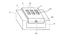
図1に、本発明の液体吐出ヘッドを示している。この液体吐出ヘッドは、記録素子基板1と、支持部材2と、電気配線基板3と、配線部4と、筐体6を有する。具体的には、直方体状の筐体6の上面に支持部材2が搭載され、支持部材2の上面に記録素子基板1が積層されている。筐体6の上面に隣接する一側面に配線部4が配置されている。そして、支持部材2上の記録素子基板1と配線部4とにまたがるように、フレキシブル配線基板である電気配線基板3が配置されている。電気配線基板3の配線部4に重なる部分を接続部(アウターリード部)30と称する。図1に示す例では、配線部4は筐体6とは別部材の配線基板であり、筐体6の一側面に貼り付けられている。ただし、配線部4は筐体6の一部であってもよい。
記録素子基板1は、液滴を吐出するための複数の吐出口1aと、図示しないが、各吐出口1aに対応する液室と、各液室内に配置されているエネルギー発生素子とを有している。吐出口1aは、電気配線基板3の開口部3aを介して外部に露出している。
Hereinafter, embodiments of the present invention will be described with reference to the drawings.
FIG. 1 shows a liquid discharge head of the present invention. The liquid discharge head includes a
The
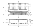
電気配線基板3と配線部4および支持部材2の接続部分の展開図を図2(a)に、その接続部分を正面から見た正面図を図2(b)に示す。図2(b)に示すように、配線部4の外表面には、複数の配線部側の接続端子41が幅方向に沿う列をなすように並べて配置されている。電気配線基板3の接続部30には、複数の電気配線基板側の接続端子31が、複数の配線部側の接続端子41の列と対向し幅方向に沿う列をなすように並べて配置されている。電気配線基板側の接続端子31につながっている電気配線は、図2(a)に破線で示されている。電気配線基板3の接続部30を配線部4に接続すると、各電気配線基板側の接続端子31が各配線部側の接続端子41にそれぞれ接触して接続される。電気配線基板3の接続部30には、幅方向の両端部R,Lの間の位置に、切り欠き部32が設けられている。この切り欠き部32は、接続部30の幅方向に延びる端縁Fの位置から形成され、接続部30の幅方向に交差する(好ましくは直交する)方向に延びている。切り欠き部32は、電気配線基板側の接続端子31の列を分断するように、電気配線基板側の接続端子同士の間に設けられ、接続部30を越えて延びている。
FIG. 2A is a development view of a connection portion between the
電気配線基板3の接続部30と配線部4は、主に各電気配線基板側の接続端子31が各配線部側の接続端子41とが熱圧着されることによって接続されている。電気配線基板3と配線部4は熱圧着時に受ける熱によってそれぞれ膨張し、それらの膨張量(伸び量)は線膨張係数の差などに応じて異なる。しかし、電気配線基板3の接続部30に切り欠き部32が設けられて、接続部30は複数(図示している例では2つ)の分割片30aに分割されており、各分割片30aの幅は小さい。物体の幅と、幅方向の熱膨張量は実質的に比例するので、幅が小さい各分割片30aの幅方向の膨張量は小さく抑えられる。また、各分割片30aの熱膨張した部分が切り欠き部32内に収まると、別の分割片30aに影響を及ぼすことはない。このように、本実施形態では、接続部30に切り欠き部32を設けることにより、各分割片30aと配線部4の幅方向の熱膨張量(伸び量)の差を小さくして、各電気配線基板側の接続端子31と各配線部側の接続端子41の幅方向の相対位置ずれを抑えている。その結果、接続不良や短絡を抑制できる。
The
このような構成であるため、図示しない液体吐出装置本体から配線部4に電気信号が供給されると、その電気信号は接続端子41,31の電気的接続によって電気配線基板3に伝達される。そして、電気信号は、電気配線基板3から記録素子基板1に伝達され、図示しないエネルギー発生素子に供給される。電気信号が供給されたエネルギー発生素子は、液室内の液体に吐出エネルギー(熱または圧力など)を付与し、吐出エネルギーが付与された液体は、吐出口1aから外部に吐出される。
Due to such a configuration, when an electrical signal is supplied to the
この液体吐出ヘッドの製造方法について説明する。前述した通り、筐体6の上面に支持部材2を積層し、一側面に配線部4となる配線基板を取り付ける。続いて、支持部材2の上に記録素子基板1を積層する。そして、記録素子基板1と配線部4の一部とにまたがるように、電気配線基板3を配置する。このとき、電気配線基板3は、接続部30に設けられている複数の接続端子31が配線部4の接続端子41とそれぞれ接触するように配置される。そして、接続部30を配線部4に接続する。具体的には、図3(a),(c)に示すように加熱ヒーター102を内蔵し平坦面101aを有する加熱圧着部材101によって、図3(b)に示すように接続部30を押圧して配線部4に押しつける。このとき、加熱圧着部材101の加熱ヒーター102によって接続部30および配線部4を加熱しながら圧力を加えることにより、各接続端子31,41が互いに熱圧着されて固定される。
A method for manufacturing the liquid discharge head will be described. As described above, the
この熱圧着時に加熱ヒーター102から加えられた熱によって、電気配線基板3と配線部4は熱膨張する。この熱膨張について説明すると、熱膨張による伸び量の絶対値は、以下の要因等によって決まる。
(1)電気配線基板3と配線部4の基材が互いに異なる材料からなる場合には、それぞれの線膨張係数が異なる。一例としては、電気配線基板3の基材が、線膨張係数が約12ppmのポリイミドからなるTABテープであり、配線部4の基材が、線膨張係数が約21ppmのガラスエポキシ樹脂である。これらの基材の材料のみを考慮すると、ガラスエポキシ樹脂の方がTABテープよりも線膨張係数が大きい。
(2)ただし、加熱圧着部材101がTABテープ(電気配線基板3)をガラスエポキシ樹脂(配線部4)に向けて押圧する際に、加熱ヒーター102からの熱は、ガラスエポキシ樹脂よりもTABテープの方により良く伝わる。
(3)短時間で効率良く液体吐出ヘッドを生産するためには、加熱圧着工程を短時間で行うことが望まれるので、接続部30を短時間で所望の温度まで昇温させる。しかし、この際に、電気配線基板3および配線部4の全体を所望の温度に加熱させるまでには至らず、部分的に熱分布が発生する。
(4)配線部4の厚さ方向に伝わる熱は、電気配線基板3の接続部30に近い側は高く、接続部30から遠い側は低くなり、熱分布が発生する。
The
(1) When the base materials of the
(2) However, when the
(3) In order to produce a liquid discharge head efficiently in a short time, it is desired to perform the thermocompression bonding process in a short time. Therefore, the temperature of the connecting
(4) The heat transmitted in the thickness direction of the
電気配線基板3と配線部4の伸び量は、それらの基材の材料の線膨張係数のみによって決まるわけではなく、前述した要因(1)〜(4)の影響(例えば熱分布の影響)も受ける。一般的な電気配線基板3の基材(TABテープ)の厚さは約0.1mmで、配線部4の基材(ガラスエポキシ樹脂)の厚さは約0.5mmである。このように配線部4が厚い場合には、基材の厚さに応じた熱分布の影響で配線部4の伸び量が小さい。
The amount of elongation of the
仮に電気配線基板3の接続部30に切り欠き部32が設けられていないと、前述した要因(1)〜(4)等から、接続部30(TABテープ)の実際の伸び量は、配線部4(ガラスエポキシ樹脂)の伸び量よりも大きくなる。図4に示すように、幅方向の伸びは、加熱されている部分の中心201を起点として、矢印で示すように両側方へ向かって生じる。電気配線基板3の幅の広い接続部30には、製造条件等にもよるが、幅方向に数μm〜数十μmの大きな伸びが発生する。この伸びの影響で、特に接続部30の外周側に位置する接続端子31,41に大きな相対位置ずれが生じ、加熱温度や加圧力等の条件によるが、例えば幅方向に数μm〜数十μm程度の相対位置ずれが生じる。それにより、電気的な接続不良が発生する場合がある。
If the
そこで本実施形態では、図2,3に示すように、電気配線基板3の接続部30に切り欠き部32が設けられている。本実施形態の切り欠き部32は、接続部30を概ね2等分するように接続部30の幅方向のほぼ中央に設けられ、幅方向に実質的に垂直に接続部30を越えて電気配線基板3の内側に向かって延びている。ただし、図2(a)に示すように、切り欠き部32の長さは、電気配線基板3の、支持部材2と接する部分までは至らない長さである。切り欠き部32の幅は、各分割片30aの熱圧着時の熱による幅方向の膨張量(伸び量)よりも大きいことが好ましい。そうすると、熱圧着後に、膨張した電気配線基板の分割片30a同士が互いに干渉することがより抑制される。また、切り欠き部32は、接続部30の幅方向の両端部の間に設ければよいが、位置ずれ抑制を考慮すると、中間付近に設けられていることが好ましい。中間付近とは、両端部間の長さを10としたときに、片方の端部から4〜6の長さにある位置を意味する。また、切り欠き部の位置とは、切り欠き部の中心の位置を意味する。
Therefore, in the present embodiment, as shown in FIGS. 2 and 3, the
以下、本発明のより具体的な実施例について説明する。
<実施例1>
図5(a),(b)に本発明の実施例1の液体吐出ヘッドの要部を示している。本実施例では、電気配線基板3の接続部30の幅方向の中央から、幅方向に実質的に垂直に延びる切り欠き部32が形成されている。この接続部30を加熱圧着部材101によって配線部4に押しつけると、図5(c)に示すように、幅方向において、各分割片30aの中心202を基点とする伸び(矢印にて図示)が生じる。このように切り欠き部32を形成することによって接続部30を複数の分割片30aに分割すると、各分割片30aの幅が小さいため幅方向の伸び量の絶対値が小さくなる。少なくとも、図4に示すように接続部30の中心201を起点として接続部全体にわたって生じる幅方向の伸びよりも、各分割片30aの中心202を基点として分割片30aごとに生じる幅方向の伸びの方が、局所的に生じる位置ずれが小さい。それにより、配線部4に対する相対位置ずれ、より詳しくは、各電気配線基板側の接続端子31と各配線部側の接続端子41の相対位置ずれを抑えて、接続不良や短絡を抑制することができる。
Hereinafter, more specific examples of the present invention will be described.
<Example 1>
FIGS. 5A and 5B show the main part of the liquid discharge head according to the first embodiment of the present invention. In the present embodiment, a
切り欠き部32の数は任意に変更可能であり、1つの切り欠き部32が形成されている場合には、伸び発生起点である分割片の中心202は2ヶ所存在し、2つの切り欠き部32が形成されている場合には、分割片の中心202は3ヶ所存在する。このような切り欠き部32の数は、電気信号の送受信に必要な電気配線基板3と配線部4の圧着面積を基準にして、以下の事項を考慮して決定される。
・電気配線基板3の接続端子31の位置のばらつきと幅のばらつき
・配線部4の接続端子41の位置のばらつきと幅のばらつき
・電気配線基板3と配線部4の位置合わせ精度
・電気配線基板3と配線部4の接続後の伸び量
これらの事項を考慮して、接続端子31,41同士の相対位置ずれ量が許容範囲を超えるおそれがある場合には、相対位置ずれ量が許容範囲内に収まるまで切り欠き部32を増やす。ただし、切り欠き部32が増えると接続部30の全体の幅が広くなるので、切り欠き部32の数は必要最小限に留めることが好ましい。
The number of the
・ Variation in position and width of
接続部30と配線部4とを接続した後に、接続部30の隣り合う分割片30a同士が切り欠き部32において干渉し合わないようにするために、接続部30の切り欠き部32の幅Wを、接続時に生じる幅方向の伸び量以上にすることが好ましい。接続部30の伸び量は主に加熱量によって決まるので、伸び量の制御は比較的容易である。
After connecting the
ただし、図5(d)に示すように、膨張時に接続部30の隣り合う分割片同士が互いに部分的に重なり合う(干渉し合う)ように、切り欠き部32の幅Wを小さくすることもできる。この場合、伸び量の制御は容易ではないが、電気配線基板3内の配線の数や大きさが一定であれば、切り欠き部32の幅Wが小さい分だけ配線のレイアウトが簡単で、接続部30の全体の幅を小さくすることができる。この構成の場合、隣り合う分割片30aが連続せずに分割されていれば、切り欠き部32の幅Wをほとんど0にすることも可能である。
However, as shown in FIG. 5D, the width W of the
切り欠き部32の長さLは、配線部4との接続部30を超える長さであるが、支持部材2に当接する部分までは至らない長さであることが好ましい。仮に、切り欠き部32の長さLが接続部30の長さ未満であると、配線部4に接続されている接続部30の一部に、配線部4に比べて大きな幅方向の熱膨張(伸び)が生じるおそれがある。その場合、一部の接続端子31,41に大きな相対位置ずれが生じ、切り欠き部32が十分な効果を奏し得ない可能性がある。本実施例では、切り欠き部32は接続部30を超える長さを有しているので、接続部30全体にわたって幅方向の熱膨張(伸び)を小さくすることができる。
The length L of the
また、仮に切り欠き部32が支持部材2に当接する部分まで設けられていると、電気配線基板3を支持部材2に接着するための接着剤が切り欠き部32からはみ出して他部材に付着するなどの影響を及ぼすおそれがある。従って、切り欠き部32から接着剤がはみ出さないようにするための接着剤の量や塗布位置の調整や、はみ出した接着剤の拭き取りなどの処置が必要になる。それに対し、本実施例では、前述したように、切り欠き部32が、支持部材2に当接する部分までは至らない長さである。それにより、電気配線基板3を支持部材2に接着するための接着剤が切り欠き部32からはみ出すことはないので、接着剤の量や塗布位置の調整や接着剤の拭き取りなどの処置が不要である。
Further, if the
本実施例では、電気配線基板3の接続部30を配線部4に接続するための加熱圧着部材101が、接続部30とほぼ同じ平面形状である。加熱圧着部材101が接続部30を加熱しながら配線部4に押しつけて、接続端子31,41同士を熱圧着させる。この加熱圧着部材101は、接続部30よりも大きい平面形状を有していてもよい。
In the present embodiment, the
<実施例2>
図6(c)に示すように、本発明の実施例2では、切り欠き部32によって分割された接続部30の各分割片30aに対応する平面形状を有する複数の小さな加熱圧着部材103が用いられている。加熱圧着部材103は、接続部30を押圧する平坦面103aが非常に高い精度(数μmオーダー)の平面性を要求される。その要求に応えるには、寸法の小さな加熱圧着部材103を用いることが、加工精度の点で有利である。
<Example 2>
As shown in FIG. 6C, in the second embodiment of the present invention, a plurality of small
図7(a)には、複数の加熱圧着部材103が保持プレート104に取り付けられており、この保持プレート104と複数の加熱圧着部材103が、図示しない駆動装置によって図7の上下方向に一体的に駆動される構成が示されている。この構成によると、接続部30の複数の分割片30aが同時に加熱および押圧されて、各電気配線基板側の接続端子31と各配線部側の接続端子41が熱圧着される。複数の小さな加熱圧着部材103を用いることにより、前述したように高精度の平坦面103aが形成しやすく、また接続作業が短時間で効率よく行える。
In FIG. 7A, a plurality of
一方、図7(b),7(c)には、複数の加熱圧着部材103が個別に駆動可能な構成が示されている。この構成によると、接続部30の複数の分割片30aを同時に加熱および押圧することも、それぞれ別々にタイムラグをおいて加熱および押圧することもできる。複数の分割片30aに対応して、独立した複数の駆動手段(図示せず)が設けられていることが好ましい。図7(b),7(c)に誇張して示すように、接続部30の各分割片30aの厚さのばらつきや配線部4の被接合面4aの凹凸が存在していても、各接続端子31を比較的均等な圧力で各接続端子41に押し当てて熱圧着させることができる。言い換えると、この構成によると、接続部30の各分割片30aの厚さや配線部4の厚さおよび被接合面4aの平面性等に関して許容範囲が比較的広く、さほど高い精度を必要としないため、作業が容易である。
図7(a)に示すように保持プレート104を用いても、図7(b),(c)に示すように複数の加熱圧着部材103が互いに独立していても、図6(a),(b)に示すように接続部30の分割片30aの幅方向の伸びが小さい構成が実現する。
On the other hand, FIGS. 7B and 7C show a configuration in which a plurality of
Even if the holding
以上説明した各実施例において、図8に示すように、電気配線基板3の接続部30と配線部4との間に異方導電性フィルム5を介在させてもよい。
In each of the embodiments described above, as shown in FIG. 8, an anisotropic
1 記録素子基板
2 支持部材
3 電気配線基板
4 配線部
30 接続部
30a 分割片
31 電気配線基板側の接続端子
32 切り欠き部
41 配線部側の接続端子
101,103 加熱圧着部材
DESCRIPTION OF
Claims (15)
前記電気配線基板の前記接続部には、前記接続部の幅方向の両端部の間の位置に切り欠き部が設けられており、前記幅方向の前記切り欠き部の長さは、前記幅方向に直交する方向の前記切り欠き部の長さよりも短く、
前記切り欠き部は、前記電気配線基板の前記接続部の前記幅方向に延びる端縁から形成されて、前記接続部を越えて延び、
前記直交する方向の前記切り欠き部の長さは、前記支持部材に当接する前記電気配線基板の前記一部までは至らない長さであることを特徴とする液体吐出ヘッド。 An electrical wiring board comprising: a wiring part; a recording element substrate having an element for applying ejection energy to the liquid; and a connection part connected to the wiring part to electrically connect the wiring part and the recording element substrate And a liquid discharge head having a support member with which a part of the electric wiring board is abutted via an adhesive ,
The connection portion of the electrical wiring board is provided with a notch portion at a position between both ends in the width direction of the connection portion, and the length of the notch portion in the width direction is the width direction. rather shorter than the length of the notch in a direction perpendicular to,
The notch is formed from an edge extending in the width direction of the connection portion of the electrical wiring board, and extends beyond the connection portion.
The length of the notch in the orthogonal direction is a length that does not reach the part of the electric wiring board that contacts the support member .
前記フレキシブル配線基板の基材の厚みは、前記配線基板の基材の厚みよりも小さい、請求項2に記載の液体吐出ヘッド。The liquid ejection head according to claim 2, wherein a thickness of the base material of the flexible wiring board is smaller than a thickness of the base material of the wiring board.
前記電気配線基板を加熱および押圧して前記配線部に接続するステップを含み、前記電気配線基板の前記接続部には、前記接続部の幅方向の両端部の間の位置に切り欠き部が設けられており、前記幅方向の前記切り欠き部の長さは、前記幅方向に直交する方向の前記切り欠き部の長さよりも短く、前記切り欠き部は、前記電気配線基板の前記接続部の前記幅方向に延びる端縁から形成されて、前記接続部を越えて延び、前記直交する方向の前記切り欠き部の長さは、前記支持部材に当接する前記電気配線基板の前記一部までは至らない長さであることを特徴とする液体吐出ヘッドの製造方法。 An electrical wiring board comprising: a wiring part; a recording element substrate having an element for applying ejection energy to the liquid; and a connection part connected to the wiring part to electrically connect the wiring part and the recording element substrate And a support member in which a part of the electrical wiring board is in contact with the adhesive, and a manufacturing method of a liquid discharge head,
A step of heating and pressing the electrical wiring board and connecting to the wiring part, the connection part of the electrical wiring board being provided with a notch at a position between both ends in the width direction of the connection part is is the length of the notch in the width direction, the rather short than a length of the notch in the direction orthogonal to the width direction, the cutout portion, the connecting portion of the electric wiring board Formed in an end edge extending in the width direction, extending beyond the connecting portion, and the length of the cutout portion in the orthogonal direction extends to the part of the electrical wiring board that contacts the support member. A method of manufacturing a liquid discharge head, characterized in that the length is not long .
Priority Applications (2)
| Application Number | Priority Date | Filing Date | Title |
|---|---|---|---|
| JP2015036827A JP6494322B2 (en) | 2015-02-26 | 2015-02-26 | Liquid discharge head and manufacturing method thereof |
| US15/051,525 US9744767B2 (en) | 2015-02-26 | 2016-02-23 | Liquid discharge head and method of manufacturing the same |
Applications Claiming Priority (1)
| Application Number | Priority Date | Filing Date | Title |
|---|---|---|---|
| JP2015036827A JP6494322B2 (en) | 2015-02-26 | 2015-02-26 | Liquid discharge head and manufacturing method thereof |
Publications (3)
| Publication Number | Publication Date |
|---|---|
| JP2016159426A JP2016159426A (en) | 2016-09-05 |
| JP2016159426A5 JP2016159426A5 (en) | 2018-03-01 |
| JP6494322B2 true JP6494322B2 (en) | 2019-04-03 |
Family
ID=56798074
Family Applications (1)
| Application Number | Title | Priority Date | Filing Date |
|---|---|---|---|
| JP2015036827A Active JP6494322B2 (en) | 2015-02-26 | 2015-02-26 | Liquid discharge head and manufacturing method thereof |
Country Status (2)
| Country | Link |
|---|---|
| US (1) | US9744767B2 (en) |
| JP (1) | JP6494322B2 (en) |
Families Citing this family (1)
| Publication number | Priority date | Publication date | Assignee | Title |
|---|---|---|---|---|
| JP2017209812A (en) * | 2016-05-23 | 2017-11-30 | キヤノン株式会社 | Liquid discharge head |
Family Cites Families (12)
| Publication number | Priority date | Publication date | Assignee | Title |
|---|---|---|---|---|
| JPS6282607A (en) * | 1985-10-07 | 1987-04-16 | キヤノン株式会社 | Wiring member |
| CA2101454C (en) * | 1992-07-31 | 1998-09-22 | Kenjiro Watanabe | Ink jet recording head, ink jet recording head cartridge, recording apparatus using the same and method of manufacturing the head |
| US5734394A (en) * | 1995-01-20 | 1998-03-31 | Hewlett-Packard | Kinematically fixing flex circuit to PWA printbar |
| JPH09286103A (en) * | 1996-04-19 | 1997-11-04 | Seiko Epson Corp | Ink jet recording head |
| JP3503677B2 (en) * | 1997-02-19 | 2004-03-08 | キヤノン株式会社 | Wiring board connection method and wiring board connection device |
| JP2002067337A (en) * | 2000-08-29 | 2002-03-05 | Ricoh Co Ltd | Ink jet head and method for manufacturing the same |
| US6715857B2 (en) * | 2002-09-05 | 2004-04-06 | Lexmark International, Inc. | Printhead carrier housing and flexible printed circuit attached to same |
| US6755509B2 (en) * | 2002-11-23 | 2004-06-29 | Silverbrook Research Pty Ltd | Thermal ink jet printhead with suspended beam heater |
| US6820967B2 (en) * | 2002-11-23 | 2004-11-23 | Silverbrook Research Pty Ltd | Thermal ink jet printhead with heaters formed from low atomic number elements |
| JP4537166B2 (en) * | 2004-10-06 | 2010-09-01 | キヤノン株式会社 | Liquid discharge head |
| JP4841010B2 (en) * | 2009-06-09 | 2011-12-21 | キヤノン株式会社 | Inkjet recording head |
| JP5825998B2 (en) * | 2011-11-30 | 2015-12-02 | キヤノン株式会社 | Ink jet recording head and method of manufacturing ink jet recording head |
-
2015
- 2015-02-26 JP JP2015036827A patent/JP6494322B2/en active Active
-
2016
- 2016-02-23 US US15/051,525 patent/US9744767B2/en active Active
Also Published As
| Publication number | Publication date |
|---|---|
| US9744767B2 (en) | 2017-08-29 |
| JP2016159426A (en) | 2016-09-05 |
| US20160250854A1 (en) | 2016-09-01 |
Similar Documents
| Publication | Publication Date | Title |
|---|---|---|
| JP6198578B2 (en) | Liquid discharge head and manufacturing method thereof | |
| US7452057B2 (en) | Flexible printhead circuit | |
| US7789488B2 (en) | Flexible wiring board and liquid discharge head | |
| KR20060097612A (en) | Device package structure, device packaging method, liquiod drop ejection method, connector, and semiconductor device | |
| JP2015231731A (en) | Liquid discharge head, method for manufacturing the same, and liquid discharge apparatus | |
| JP6175798B2 (en) | Liquid ejection apparatus and flexible wiring board connection method | |
| JP6494322B2 (en) | Liquid discharge head and manufacturing method thereof | |
| JP4661228B2 (en) | Droplet discharge head and droplet discharge apparatus | |
| JP7229753B2 (en) | Manufacturing method of liquid ejection head | |
| JP5825998B2 (en) | Ink jet recording head and method of manufacturing ink jet recording head | |
| US10933669B2 (en) | Print element board, liquid ejection head, and liquid ejection apparatus | |
| JP5994324B2 (en) | Droplet discharge device | |
| JP2010260187A (en) | Wiring unit, manufacturing method for wiring unit, liquid ejection head, and manufacturing method for liquid ejection head | |
| JP6523067B2 (en) | Liquid jet head and liquid jet apparatus | |
| JP5147382B2 (en) | SEMICONDUCTOR ELEMENT SUBSTRATE, INK JET HEAD USING THE ELEMENT SUBSTRATE, AND SEMICONDUCTOR ELEMENT SUBSTRATE ELECTROCONNECTION METHOD | |
| JPH06316065A (en) | Ink jet device | |
| US11446927B2 (en) | Method of bonding printed circuit sheets | |
| JP2015150793A (en) | Manufacturing method of wiring mounting structure, manufacturing method of liquid ejection head and wiring mounting structure | |
| US20230109029A1 (en) | Liquid ejection head and manufacturing method for liquid ejection head | |
| JP2006341385A (en) | Ink jet recording head | |
| US20210039388A1 (en) | Ink jet recording head and ink jet recording apparatus | |
| US20150202870A1 (en) | Liquid ejecting head and liquid ejecting apparatus | |
| JP2023004128A (en) | Liquid discharge head | |
| JP2021187010A (en) | Method and apparatus for manufacturing liquid discharge head | |
| JP6338452B2 (en) | Method for manufacturing liquid discharge head |
Legal Events
| Date | Code | Title | Description |
|---|---|---|---|
| A621 | Written request for application examination |
Free format text: JAPANESE INTERMEDIATE CODE: A621 Effective date: 20171218 |
|
| A521 | Written amendment |
Free format text: JAPANESE INTERMEDIATE CODE: A523 Effective date: 20180117 |
|
| A131 | Notification of reasons for refusal |
Free format text: JAPANESE INTERMEDIATE CODE: A131 Effective date: 20181002 |
|
| A977 | Report on retrieval |
Free format text: JAPANESE INTERMEDIATE CODE: A971007 Effective date: 20180928 |
|
| A521 | Written amendment |
Free format text: JAPANESE INTERMEDIATE CODE: A523 Effective date: 20181129 |
|
| TRDD | Decision of grant or rejection written | ||
| A01 | Written decision to grant a patent or to grant a registration (utility model) |
Free format text: JAPANESE INTERMEDIATE CODE: A01 Effective date: 20190205 |
|
| A61 | First payment of annual fees (during grant procedure) |
Free format text: JAPANESE INTERMEDIATE CODE: A61 Effective date: 20190305 |
|
| R151 | Written notification of patent or utility model registration |
Ref document number: 6494322 Country of ref document: JP Free format text: JAPANESE INTERMEDIATE CODE: R151 |