JP6485454B2 - Information processing device - Google Patents

Information processing device Download PDF

Info

Publication number
JP6485454B2
JP6485454B2 JP2016513616A JP2016513616A JP6485454B2 JP 6485454 B2 JP6485454 B2 JP 6485454B2 JP 2016513616 A JP2016513616 A JP 2016513616A JP 2016513616 A JP2016513616 A JP 2016513616A JP 6485454 B2 JP6485454 B2 JP 6485454B2
Authority
JP
Japan
Prior art keywords
crack
unit
information
displacement
external force
Prior art date
Legal status (The legal status is an assumption and is not a legal conclusion. Google has not performed a legal analysis and makes no representation as to the accuracy of the status listed.)
Active
Application number
JP2016513616A
Other languages
Japanese (ja)
Other versions
JPWO2015159469A1 (en
Inventor
太田 雅彦
雅彦 太田
巡 高田
巡 高田
浩 今井
浩 今井
敦史 幡生
敦史 幡生
中野 学
学 中野
朕 王
朕 王
裕三 仙田
裕三 仙田
Current Assignee (The listed assignees may be inaccurate. Google has not performed a legal analysis and makes no representation or warranty as to the accuracy of the list.)
NEC Corp
Original Assignee
NEC Corp
Priority date (The priority date is an assumption and is not a legal conclusion. Google has not performed a legal analysis and makes no representation as to the accuracy of the date listed.)
Filing date
Publication date
Application filed by NEC Corp filed Critical NEC Corp
Publication of JPWO2015159469A1 publication Critical patent/JPWO2015159469A1/en
Application granted granted Critical
Publication of JP6485454B2 publication Critical patent/JP6485454B2/en
Active legal-status Critical Current
Anticipated expiration legal-status Critical

Links

Images

Classifications

    • GPHYSICS
    • G01MEASURING; TESTING
    • G01NINVESTIGATING OR ANALYSING MATERIALS BY DETERMINING THEIR CHEMICAL OR PHYSICAL PROPERTIES
    • G01N21/00Investigating or analysing materials by the use of optical means, i.e. using sub-millimetre waves, infrared, visible or ultraviolet light
    • G01N21/84Systems specially adapted for particular applications
    • G01N21/88Investigating the presence of flaws or contamination
    • G01N21/8851Scan or image signal processing specially adapted therefor, e.g. for scan signal adjustment, for detecting different kinds of defects, for compensating for structures, markings, edges
    • GPHYSICS
    • G01MEASURING; TESTING
    • G01BMEASURING LENGTH, THICKNESS OR SIMILAR LINEAR DIMENSIONS; MEASURING ANGLES; MEASURING AREAS; MEASURING IRREGULARITIES OF SURFACES OR CONTOURS
    • G01B11/00Measuring arrangements characterised by the use of optical techniques
    • G01B11/16Measuring arrangements characterised by the use of optical techniques for measuring the deformation in a solid, e.g. optical strain gauge
    • GPHYSICS
    • G01MEASURING; TESTING
    • G01NINVESTIGATING OR ANALYSING MATERIALS BY DETERMINING THEIR CHEMICAL OR PHYSICAL PROPERTIES
    • G01N21/00Investigating or analysing materials by the use of optical means, i.e. using sub-millimetre waves, infrared, visible or ultraviolet light
    • G01N21/84Systems specially adapted for particular applications
    • G01N21/88Investigating the presence of flaws or contamination
    • GPHYSICS
    • G06COMPUTING; CALCULATING OR COUNTING
    • G06TIMAGE DATA PROCESSING OR GENERATION, IN GENERAL
    • G06T7/00Image analysis
    • G06T7/0002Inspection of images, e.g. flaw detection
    • G06T7/0004Industrial image inspection
    • GPHYSICS
    • G06COMPUTING; CALCULATING OR COUNTING
    • G06TIMAGE DATA PROCESSING OR GENERATION, IN GENERAL
    • G06T2207/00Indexing scheme for image analysis or image enhancement
    • G06T2207/30Subject of image; Context of image processing
    • G06T2207/30108Industrial image inspection
    • G06T2207/30132Masonry; Concrete

Landscapes

  • Physics & Mathematics (AREA)
  • General Physics & Mathematics (AREA)
  • Engineering & Computer Science (AREA)
  • Pathology (AREA)
  • General Health & Medical Sciences (AREA)
  • Health & Medical Sciences (AREA)
  • Life Sciences & Earth Sciences (AREA)
  • Chemical & Material Sciences (AREA)
  • Analytical Chemistry (AREA)
  • Biochemistry (AREA)
  • Immunology (AREA)
  • Computer Vision & Pattern Recognition (AREA)
  • Signal Processing (AREA)
  • Quality & Reliability (AREA)
  • Theoretical Computer Science (AREA)
  • Length Measuring Devices By Optical Means (AREA)
  • Investigating Materials By The Use Of Optical Means Adapted For Particular Applications (AREA)
  • Image Processing (AREA)
  • Image Analysis (AREA)

Description

本発明は、構造物のひび割れを検出する情報処理装置、プログラム、情報処理方法に関する。   The present invention relates to an information processing apparatus, a program, and an information processing method for detecting cracks in a structure.

トンネルや橋梁などのコンクリート構造物においては、構造物の表面に発生するひび割れが当該構造物の健全度に影響を及ぼすことが知られている。そのため、構造物の健全度を正確に判断するためには、ひび割れを正確に検出することが必要となる。   In concrete structures such as tunnels and bridges, it is known that cracks generated on the surface of the structure affect the soundness of the structure. Therefore, it is necessary to accurately detect cracks in order to accurately determine the soundness of the structure.

ひび割れを検出するための方法としては、例えば、目視によるひび割れの検出という方法がある。しかしながら、目視によるひび割れの検出では、ひび割れを正確に検出することが出来るか否かは、目視を行う人物の能力に依存することになる。そのため、目視を行う人物の能力によっては、正確にひび割れを検出することが出来ないことがあった。このように、目視によるひび割れの検出という方法には、人物の能力に依存するという問題が生じていた。そこで、目視によるひび割れの検出以外の、人物の能力に依存しないひび割れ検出を行う技術が様々考案されている。   As a method for detecting a crack, for example, there is a method of visually detecting a crack. However, in the detection of cracks by visual observation, whether or not the cracks can be accurately detected depends on the ability of the person performing the visual inspection. For this reason, the cracks may not be accurately detected depending on the ability of the person who performs visual observation. As described above, the method of visually detecting cracks has a problem that it depends on the ability of a person. Various techniques have been devised for detecting cracks that do not depend on the ability of a person other than visual crack detection.

例えば、構造物を撮像手段で撮像して得られた画像を所定の閾値で2値化処理して画像からひび割れに対応する画像部分を検出することが本発明に関連する第1の関連技術として提案されている(例えば特許文献1参照)。   For example, as a first related technique related to the present invention, an image obtained by imaging a structure with an imaging unit is binarized with a predetermined threshold to detect an image portion corresponding to a crack from the image. It has been proposed (for example, see Patent Document 1).

また、構造物表面を照らす光源の角度を変化させながら構造物を撮像手段で複数回撮像し、各画像の同一測定対象部位の画素値を比較することによって、ひび割れ画像を検出することが本発明に関連する第2の関連技術として提案されている(例えば特許文献2参照)。   Further, the present invention is to detect a cracked image by imaging a structure a plurality of times with an imaging means while changing the angle of a light source that illuminates the surface of the structure, and comparing pixel values of the same measurement target portion of each image. It has been proposed as a second related technique related to (see, for example, Patent Document 2).

また、構造物を撮像した画像に対して、ウェーブレット変換を用いて低周波成分を除去する処理を行うことにより、空間変化率が小さい構造物表面の染みや汚れを除去した2値化画像データを作成し、この2値化画像データからひび割れ画像を検出することが本発明に関連する第3の関連技術として提案されている(例えば特許文献3参照)。   In addition, binarized image data obtained by removing stains and dirt on the surface of the structure with a small spatial change rate by performing processing for removing low-frequency components using wavelet transform on the image obtained by capturing the structure. Producing and detecting a cracked image from the binarized image data has been proposed as a third related technique related to the present invention (see, for example, Patent Document 3).

特開2003−35528号公報JP 2003-35528 A 特開2006−118913号公報JP 2006-118913 A 特開2006−162477号公報JP 2006-162477 A

しかしながら、上記第1乃至第3の関連技術では、構造物表面に現れるひび割れと画像的に類似している打設の継ぎ目やタイル目地、模様、表面の汚れなどをひび割れとして誤検出するという課題がある。その理由は、上記第1乃至第3の関連技術は、構造物を撮影した画像からひび割れ画像を検出するため、ひび割れ画像と画像的に類似する模様などとを機械的に区別することができないためである。   However, in the first to third related technologies, there is a problem that a joint, a tile joint, a pattern, a dirt on the surface, and the like that are imagewise similar to a crack appearing on the surface of a structure are erroneously detected as a crack. is there. The reason is that the first to third related techniques detect a cracked image from an image obtained by photographing a structure, and therefore cannot mechanically distinguish between a cracked image and a pattern similar in image. It is.

そこで、本発明の目的は、構造物表面に現れるひび割れと画像的に類似している模様などをひび割れとして誤検出する、という問題を解決する情報処理装置を提供することにある。   Accordingly, an object of the present invention is to provide an information processing apparatus that solves the problem of erroneously detecting, as a crack, a pattern that is imagewise similar to a crack appearing on the surface of a structure.

かかる目的を達成するため本発明の一形態である情報処理装置は、
構造物上のひび割れを検出する情報処理装置であって、
前記構造物上の少なくとも2つの測定点における位置の変化を検出する測定点位置変化検出手段と、
前記測定点位置変化検出手段が検出した前記各測定点の位置の変化に基づいてひび割れを検出するひび割れ検出手段と、
を有する。
In order to achieve such an object, an information processing apparatus according to an aspect of the present invention provides:
An information processing device for detecting cracks on a structure,
Measuring point position change detecting means for detecting a change in position at least two measuring points on the structure;
Crack detecting means for detecting a crack based on a change in position of each measurement point detected by the measurement point position change detecting means;
Have

また、本発明の他の形態である情報処理方法は、
構造物上のひび割れを検出する情報処理方法であって、
前記構造物上の少なくとも2つの測定点における位置の変化を検出し、
検出した前記各測定点の位置の変化に基づいてひび割れを検出する。
In addition, an information processing method according to another aspect of the present invention includes:
An information processing method for detecting cracks on a structure,
Detecting a change in position at at least two measurement points on the structure;
Cracks are detected based on the detected change in position of each measurement point.

また、本発明の他の形態であるプログラムは、
コンピュータを、
前記構造物上の少なくとも2つの測定点における位置の変化を検出する測定点位置変化検出手段と、
前記測定点位置変化検出手段が検出した前記各測定点の位置の変化に基づいてひび割れを検出するひび割れ検出手段と
して機能させる。
Moreover, the program which is the other form of this invention is:
Computer
Measuring point position change detecting means for detecting a change in position at least two measuring points on the structure;
It is made to function as a crack detection means which detects a crack based on the change of the position of each said measurement point which the said measurement point position change detection means detected.

本発明は、以上のように構成されることにより、画像的に類似している模様などをひび割れとして誤検出することなく構造物表面に現れるひび割れを検出する情報処理装置を提供することが出来る。   According to the present invention configured as described above, it is possible to provide an information processing apparatus that detects a crack appearing on the surface of a structure without erroneously detecting an image-like pattern or the like as a crack.

本発明の第1の実施形態に係るひび割れ検出装置の概要を説明するための図である。It is a figure for demonstrating the outline | summary of the crack detection apparatus which concerns on the 1st Embodiment of this invention. 本発明の第1の実施形態に係るひび割れ検出装置の構成を示すブロック図である。It is a block diagram which shows the structure of the crack detection apparatus which concerns on the 1st Embodiment of this invention. 本発明の第1の実施形態に係るひび割れ検出装置における画像情報の構成例を示す図である。It is a figure which shows the structural example of the image information in the crack detection apparatus which concerns on the 1st Embodiment of this invention. 本発明の第1の実施形態に係るひび割れ検出装置における変位特徴量情報の構成例を示す図である。It is a figure which shows the structural example of the displacement feature-value information in the crack detection apparatus which concerns on the 1st Embodiment of this invention. 本発明の第1の実施形態に係るひび割れ検出装置におけるひび割れ検出の処理を説明するための図である。It is a figure for demonstrating the process of the crack detection in the crack detection apparatus which concerns on the 1st Embodiment of this invention. 本発明の第1の実施形態に係るひび割れ検出装置の動作を示すフローチャートである。It is a flowchart which shows operation | movement of the crack detection apparatus which concerns on the 1st Embodiment of this invention. 本発明の第2の実施形態に係るひび割れ検出装置の構成を示すブロック図である。It is a block diagram which shows the structure of the crack detection apparatus which concerns on the 2nd Embodiment of this invention. 本発明の第2の実施形態に係るひび割れ検出装置における変位分布情報の構成例を示す図である。It is a figure which shows the structural example of the displacement distribution information in the crack detection apparatus which concerns on the 2nd Embodiment of this invention. 本発明の第2の実施形態に係るひび割れ検出装置における領域情報の構成例を示す図である。It is a figure which shows the structural example of the area | region information in the crack detection apparatus which concerns on the 2nd Embodiment of this invention. 本発明の第2の実施形態に係るひび割れ検出装置における領域分割の処理を説明するための図である。It is a figure for demonstrating the process of the area | region division in the crack detection apparatus concerning the 2nd Embodiment of this invention. 本発明の第2の実施形態に係るひび割れ検出装置における領域分割の処理を説明するための図である。It is a figure for demonstrating the process of the area | region division in the crack detection apparatus concerning the 2nd Embodiment of this invention. 本発明の第2の実施形態に係るひび割れ検出装置の動作を説明するためのフローチャートである。It is a flowchart for demonstrating operation | movement of the crack detection apparatus which concerns on the 2nd Embodiment of this invention. 本発明の第3の実施形態に係る構造物健全度評価装置の構成を示すブロック図である。It is a block diagram which shows the structure of the structure soundness evaluation apparatus which concerns on the 3rd Embodiment of this invention. 本発明の第3の実施形態に係る構造物健全度評価装置におけるひび割れ幅変動量情報の構成例を示す図である。It is a figure which shows the structural example of the crack width variation | change_quantity information in the structure soundness evaluation apparatus which concerns on the 3rd Embodiment of this invention. 本発明の第3の実施形態に係る構造物健全度評価装置における基準ひび割れ幅変動量情報の構成例を示す図である。It is a figure which shows the structural example of the reference crack width fluctuation amount information in the structure soundness evaluation apparatus which concerns on the 3rd Embodiment of this invention. 本発明の第3の実施形態に係る構造物健全度評価装置における健全度情報の構成例を示す図である。It is a figure which shows the structural example of the soundness information in the structure soundness evaluation apparatus which concerns on the 3rd Embodiment of this invention. 本発明の第3の実施形態に係る構造物健全度評価装置の動作を説明するためのフローチャートである。It is a flowchart for demonstrating operation | movement of the structure soundness evaluation apparatus which concerns on the 3rd Embodiment of this invention. 本発明の第3の実施形態に係る構造物健全度評価装置の他の構成例を示すブロック図である。It is a block diagram which shows the other structural example of the structure soundness evaluation apparatus which concerns on the 3rd Embodiment of this invention. 本発明の第4の実施形態に係る構造物健全度評価装置の構成を示すブロック図である。It is a block diagram which shows the structure of the structure soundness evaluation apparatus which concerns on the 4th Embodiment of this invention. 本発明の第4の実施形態に係る構造物健全度評価装置における外力情報の構成例を示す図である。It is a figure which shows the structural example of the external force information in the structure soundness evaluation apparatus which concerns on the 4th Embodiment of this invention. 本発明の第4の実施形態に係る構造物健全度評価装置における基準外力印加時ひび割れ幅変動量情報の構成例を示す図である。It is a figure which shows the structural example of the crack width variation | change_quantity information at the time of the reference | standard external force application in the structure soundness evaluation apparatus which concerns on the 4th Embodiment of this invention. 本発明の第4の実施形態に係る構造物健全度評価装置における基準外力印加時ひび割れ幅変動量の算出の一例を示す図である。It is a figure which shows an example of calculation of the crack width variation | change_quantity at the time of the reference | standard external force application in the structure soundness evaluation apparatus which concerns on the 4th Embodiment of this invention. 本発明の第4の実施形態に係る構造物健全度評価装置の動作を説明するためのフローチャートである。It is a flowchart for demonstrating operation | movement of the structure soundness evaluation apparatus which concerns on the 4th Embodiment of this invention. 本発明の第5の実施形態に係るひび割れ深さ評価装置の構成を示すブロック図である。It is a block diagram which shows the structure of the crack depth evaluation apparatus which concerns on the 5th Embodiment of this invention. 本発明の第5の実施形態に係るひび割れ深さ評価装置におけるひび割れ深さ情報の構成例を示す図である。It is a figure which shows the structural example of the crack depth information in the crack depth evaluation apparatus which concerns on the 5th Embodiment of this invention. 本発明の第5の実施形態に係るひび割れ深さ評価装置の動作を説明するためのフローチャートである。It is a flowchart for demonstrating operation | movement of the crack depth evaluation apparatus which concerns on the 5th Embodiment of this invention. 本発明の第5の実施形態に係るひび割れ深さ評価装置を用いて行う実験系の構成の一例を示す図である。It is a figure which shows an example of a structure of the experimental system performed using the crack depth evaluation apparatus which concerns on the 5th Embodiment of this invention. 本発明の第5の実施形態に係るひび割れ深さ評価装置が評価するひび割れの深さとひび割れ幅変動量と荷重との関係の一例を示す図である。It is a figure which shows an example of the relationship between the crack depth, the crack width variation | change_quantity, and a load which the crack depth evaluation apparatus which concerns on the 5th Embodiment of this invention evaluates. 本発明の第6の実施形態に係る構造物健全度評価装置の構成を示すブロック図である。It is a block diagram which shows the structure of the structure soundness evaluation apparatus which concerns on the 6th Embodiment of this invention. 本発明の第6の実施形態に係る構造物健全度評価装置における基準ひび割れ深さ情報の構成例を示す図である。It is a figure which shows the structural example of the reference | standard crack depth information in the structure soundness evaluation apparatus which concerns on the 6th Embodiment of this invention. 本発明の第6の実施形態に係る構造物健全度評価装置の動作を説明するためのフローチャートである。It is a flowchart for demonstrating operation | movement of the structure soundness evaluation apparatus which concerns on the 6th Embodiment of this invention. 本発明の第7の実施形態に係るひび割れ検出装置の構成の概要を示すブロック図である。It is a block diagram which shows the outline | summary of a structure of the crack detection apparatus concerning the 7th Embodiment of this invention.

次に本発明の実施の形態について図面を参照して詳細に説明する。
[第1の実施形態]
図1を参照すると、本発明の第1の実施形態におけるひび割れ検出装置1は、画像撮影部11が撮影した構造物6(トンネルや橋梁など)の画像を用いて、構造物6上に発生しているひび割れ61を検出する機能を有している。一般に、構造物6に生じているひび割れ61の幅は、荷重がかかる、風の影響、その他様々な影響を受けて、変動することが知られている。しかしながら、上記特徴は、何らかの方法により発見されたひび割れ61に対する処理で用いられることはあっても、ひび割れ61を発見するために用いられることはなかった。本発明の第1の実施形態におけるひび割れ検出装置1は、上記構造物6に生じているひび割れ61の幅が変動することを利用して当該構造物6上に発生しているひび割れ61を検出する装置である。
Next, embodiments of the present invention will be described in detail with reference to the drawings.
[First embodiment]
Referring to FIG. 1, the crack detection apparatus 1 according to the first embodiment of the present invention is generated on a structure 6 using an image of the structure 6 (tunnel, bridge, etc.) photographed by the image photographing unit 11. It has a function of detecting cracks 61 that are present. In general, it is known that the width of the crack 61 generated in the structure 6 varies under the influence of a load, wind, and various other effects. However, although the above feature is used in the processing for the crack 61 discovered by some method, it is not used for finding the crack 61. The crack detection device 1 according to the first embodiment of the present invention detects the crack 61 generated on the structure 6 by utilizing the fluctuation of the width of the crack 61 generated in the structure 6. Device.

図2を参照すると、ひび割れ検出装置1は、主な構成要素として、画像撮影部11と、通信I/F部12と、操作入力部13と、画面表示部14と、記憶部15と、演算処理部16と、を有している。   Referring to FIG. 2, the crack detection device 1 includes, as main components, an image capturing unit 11, a communication I / F unit 12, an operation input unit 13, a screen display unit 14, a storage unit 15, and a calculation. And a processing unit 16.

画像撮影部11は、デジタルカメラやデジタルビデオカメラなどの画像撮影装置からなり、ひび割れ検出の対象となる構造物6を撮影して画像データを取得する機能を有している。本実施形態における画像撮影部11は、被写体となる構造物6のうちの同一範囲(ひび割れ検出の対象となる範囲)を、例えば予め定められた時間間隔で少なくとも2枚撮影する。なお、画像撮影部11は、連続的に構造物6を撮影することで、時系列の画像データを取得しても構わない。   The image photographing unit 11 includes an image photographing device such as a digital camera or a digital video camera, and has a function of photographing the structure 6 that is a target of crack detection and acquiring image data. The image capturing unit 11 according to the present embodiment captures at least two images of the same range (a range to be subjected to crack detection) in the structure 6 serving as a subject, for example, at a predetermined time interval. Note that the image capturing unit 11 may acquire time-series image data by continuously capturing the structure 6.

通信I/F部12は、専用のデータ通信回路からなり、通信回線を介して接続された各種装置との間でデータ通信を行う機能を有している。   The communication I / F unit 12 includes a dedicated data communication circuit, and has a function of performing data communication with various devices connected via a communication line.

操作入力部13は、キーボードやマウスなどの操作入力装置からなり、オペレータの操作を検出して演算処理部16に出力する機能を有している。   The operation input unit 13 includes an operation input device such as a keyboard and a mouse, and has a function of detecting an operator operation and outputting the operation to the arithmetic processing unit 16.

画面表示部14は、LCD(Liquid Crystal Display)やPDP(Plasma Display Panel)などの画面表示装置からなる。画面表示部14は、演算処理部16からの指示に応じて、構造物6に生じているひび割れ61の情報などの各種情報を画面表示する機能を有している。   The screen display unit 14 includes a screen display device such as an LCD (Liquid Crystal Display) or a PDP (Plasma Display Panel). The screen display unit 14 has a function of displaying various information such as information on the crack 61 generated in the structure 6 on the screen in response to an instruction from the arithmetic processing unit 16.

記憶部15は、ハードディスクやメモリなどの記憶装置である。記憶部15は、演算処理部16における各種処理に必要な処理情報やプログラム153を記憶する機能を有している。プログラム153は、演算処理部16に読み込まれて実行されることにより各種処理部を実現するプログラムである。プログラム153は、通信I/F部12などのデータ入出力機能を介して外部装置(図示せず)や記憶媒体(図示せず)から予め読み込まれ、記憶部15に保存されている。記憶部15で記憶される主な情報としては、画像情報151と変位特徴量情報152とがある。   The storage unit 15 is a storage device such as a hard disk or a memory. The storage unit 15 has a function of storing processing information and programs 153 necessary for various processes in the arithmetic processing unit 16. The program 153 is a program that implements various processing units by being read and executed by the arithmetic processing unit 16. The program 153 is read in advance from an external device (not shown) or a storage medium (not shown) via a data input / output function such as the communication I / F unit 12 and stored in the storage unit 15. Main information stored in the storage unit 15 includes image information 151 and displacement feature amount information 152.

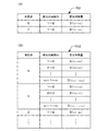
画像情報151は、画像撮影部11が構造物6を撮影することで取得した、ひび割れ61の検出の対象となる範囲の画像データを示す情報である。図3(A)は、画像情報151の構成例である。図3(A)を参照すると、画像情報151には、画像データと、当該画像データを識別するための情報である画像IDとが記憶されている。例えば、図3(A)の1行目は、画像ID「1」と対応づけて画像データ「I」が記憶されていることを示している。The image information 151 is information indicating image data in a range to be detected for the crack 61 acquired by the image capturing unit 11 capturing the structure 6. FIG. 3A is a configuration example of the image information 151. Referring to FIG. 3A, the image information 151 stores image data and an image ID that is information for identifying the image data. For example, the first line in FIG. 3A indicates that image data “I 1 ” is stored in association with the image ID “1”.

なお、画像情報151には、撮影範囲に応じて画像データが記憶されている。例えば、図3(A)には、画像ID「1」に対応付けて画像データ「I」が記憶されており、画像ID「2」に対応付けて画像データ「I」が記憶されている。この画像データ「I」と画像データ「I」とは、画像撮影部11が同一範囲を撮影することで取得した画像データとなる。The image information 151 stores image data according to the shooting range. For example, in FIG. 3A, the image data “I 1 ” is stored in association with the image ID “1”, and the image data “I 2 ” is stored in association with the image ID “2”. Yes. The image data “I 1 ” and the image data “I 2 ” are image data acquired by the image capturing unit 11 capturing the same range.

また、画像情報151には、例えば、撮影時間が古い順(取得時間が古い順)で画像データが記憶されている。つまり、画像情報151では、撮影時間が古い方から順番に、画像IDが振られていることになる。例えば、図3(A)は、画像ID「1」に対応する画像データ「I」が撮影された後に、画像ID「2」に対応する画像データ「I」が撮影されたことを示している。また、画像撮影部11が時系列の画像データを取得した場合には、例えば図3(B)で示すように、画像情報151は、時系列の画像データを古い順で記憶することが出来る。また、画像情報151には、画像データを取得した時刻を示す情報が含まれていても構わない。In addition, the image information 151 stores image data in the order of shooting time (in order of acquisition time), for example. That is, in the image information 151, image IDs are assigned in order from the oldest shooting time. For example, FIG. 3 (A) indicates that the image data corresponding to the image ID "1", "I 1" it is after being captured, the image data corresponding to an image ID "2", "I 2" is taken ing. When the image capturing unit 11 acquires time-series image data, for example, as illustrated in FIG. 3B, the image information 151 can store the time-series image data in the oldest order. The image information 151 may include information indicating the time when the image data is acquired.

変位特徴量情報152は、別時刻に撮影された同一範囲の画像データから生成される、画像データ内の任意の領域(測定点)の時間的な位置の変化を示す情報である。変位特徴量情報152は、少なくとも2つの任意の領域の時間的な位置の変化を示す情報を含んで構成されている。   The displacement feature amount information 152 is information indicating a change in temporal position of an arbitrary region (measurement point) in the image data, which is generated from image data in the same range taken at another time. The displacement feature amount information 152 includes information indicating changes in the temporal position of at least two arbitrary regions.

図4(A)は、変位特徴量情報152の構成例である。図4(A)を参照すると、変位特徴量情報152は、測定点と算出元画像IDと変位特徴量とを有している。つまり、変位特徴量情報152には、時間的な位置の変化を追う対象となる測定点ごとに、変位特徴量を算出する対象となる画像データを画像IDで示す算出元画像IDと測定点の位置の変化を示す変位特徴量(変位方向、変位量)とが対応付けて記憶されている。例えば、図4(A)の1行目は、画像ID「1」の画像データと画像ID「2」の画像データと(つまり、画像データ「I」、「I」)を用いて算出された変位特徴量「D(X1→X2)」を示している。FIG. 4A is a configuration example of the displacement feature amount information 152. Referring to FIG. 4A, the displacement feature amount information 152 includes a measurement point, a calculation source image ID, and a displacement feature amount. In other words, the displacement feature amount information 152 includes, for each measurement point that is the target of tracking a change in position over time, the calculation source image ID that indicates the image data that is the target of calculating the displacement feature amount and the measurement point. Displacement feature amounts (displacement direction, displacement amount) indicating changes in position are stored in association with each other. For example, the first line in FIG. 4A is calculated using the image data with the image ID “1” and the image data with the image ID “2” (that is, the image data “I 1 ”, “I 2 ”). The displacement feature quantity “D (X1 → X2) ” is shown.

なお、変位特徴量情報152は、例えば図4(B)で示すように、時系列の画像データそれぞれに応じた変位特徴量を記憶することが出来る。また、変位特徴量情報152は、図4(B)で示すように、2つ以上の複数の測定点の変位特徴量を記憶することが出来る。   The displacement feature amount information 152 can store displacement feature amounts corresponding to time-series image data, for example, as shown in FIG. 4B. Further, as shown in FIG. 4B, the displacement feature amount information 152 can store displacement feature amounts of two or more measurement points.

演算処理部16は、MPUなどのマイクロプロセッサとその周辺回路を有し、記憶部15からプログラム153を読み込んで実行することにより、上記ハードウェアとプログラム153とを協働させて各種処理部を実現する機能を有している。演算処理部16で実現される主な処理部として、画像取得部161と変位特徴量算出部162(測定点位置変化検出手段)とひび割れ検出部163とがある。   The arithmetic processing unit 16 includes a microprocessor such as an MPU and its peripheral circuits, and reads the program 153 from the storage unit 15 and executes it, thereby realizing various processing units by cooperating the hardware and the program 153. It has a function to do. As main processing units realized by the arithmetic processing unit 16, there are an image acquisition unit 161, a displacement feature amount calculation unit 162 (measurement point position change detection means), and a crack detection unit 163.

画像取得部161は、画像撮影部11から画像データを取得して、記憶部15の画像情報151に当該取得した画像データを保存する機能を有する。つまり、画像取得部161は、画像撮影部11から画像データを取得する。そして、画像取得部161は、当該取得した画像データを記憶部15の画像情報151に保存する。   The image acquisition unit 161 has a function of acquiring image data from the image capturing unit 11 and storing the acquired image data in the image information 151 of the storage unit 15. That is, the image acquisition unit 161 acquires image data from the image capturing unit 11. Then, the image acquisition unit 161 stores the acquired image data in the image information 151 of the storage unit 15.

変位特徴量算出部162は、記憶部15から画像情報151を読み出し、画像データ内の任意の領域(測定点)の時間的な位置の変化を検出して変位特徴量を算出する機能を有する。具体的には、本実施形態における変位特徴量算出部162は、読み出した画像データにテンプレートマッチング法やデジタル画像相関法に代表される領域ベースの画像探索手法を適用して、測定点を中心とする領域の時間的な位置の変化を検出し、変位特徴量を算出する。例えば、変位特徴量算出部162は、記憶部15の画像情報151から画像データ「I」と画像データ「I」とを読み出す。そして、変位特徴量算出部162は、画像データ「I」内の任意の領域Xが画像データ「I」内のどの領域に対応するかを追跡する。これにより、変位特徴量算出部162は、画像データ「I」内の任意の領域Xの位置が、画像データ「I」では領域Xの位置に移動していることを検出する。そして、変位特徴量算出部162は、検出結果に基づいて、変位方向と変位量とからなる変位特徴量を算出する。なお、変位特徴量算出部162は、任意の測定点として点ベースの変位を検出するよう構成しても構わない。この場合には、変位特徴量算出部162は、測定点となる画像中の特徴点として、輝度勾配、コーナー、エッジなどの画像特徴点やSIFT(Scale Invariant Feature Transform)などの局所特徴を利用し、測定点の時間的な位置の変化を検出し、変位特徴量を算出することが出来る。The displacement feature amount calculation unit 162 has a function of reading the image information 151 from the storage unit 15 and calculating a displacement feature amount by detecting a temporal change in an arbitrary region (measurement point) in the image data. Specifically, the displacement feature amount calculation unit 162 in the present embodiment applies a region-based image search method typified by a template matching method or a digital image correlation method to the read image data, and focuses on the measurement point. A change in temporal position of the area to be detected is detected, and a displacement feature amount is calculated. For example, the displacement feature amount calculation unit 162 reads the image data “I 1 ” and the image data “I 2 ” from the image information 151 in the storage unit 15. Then, the displacement characteristic amount calculation unit 162, any region X 1 of the image data in the "I 1" to track corresponds to which region of the image data "I 2". Thereby, the displacement feature amount calculation unit 162 detects that the position of the arbitrary region X 1 in the image data “I 1 ” has moved to the position of the region X 2 in the image data “I 2 ”. And the displacement feature-value calculation part 162 calculates the displacement feature-value which consists of a displacement direction and a displacement amount based on a detection result. Note that the displacement feature amount calculation unit 162 may be configured to detect a point-based displacement as an arbitrary measurement point. In this case, the displacement feature amount calculation unit 162 uses image feature points such as luminance gradient, corner, and edge, and local features such as SIFT (Scale Invariant Feature Transform) as feature points in the image serving as measurement points. It is possible to detect a change in the time position of the measurement point and calculate a displacement feature amount.

その後、変位特徴量算出部162は、算出した変位特徴量を、当該変位特徴量を算出する基となった画像データを示す画像IDと対応付けて、変位特徴量情報152として記憶部15に保存する。なお、変位特徴量算出部162は、少なくとも2か所の測定点に対して、変位特徴量を算出する。   Thereafter, the displacement feature amount calculation unit 162 stores the calculated displacement feature amount in the storage unit 15 as the displacement feature amount information 152 in association with the image ID indicating the image data from which the displacement feature amount is calculated. To do. The displacement feature amount calculation unit 162 calculates a displacement feature amount for at least two measurement points.

ひび割れ検出部163は、記憶部15から変位特徴量情報152を読み出し、測定点の間に生じているひび割れ61を検出する機能を有する。例えば、ひび割れ検出部163は、測定点Xに対する変位特徴量「D(X1→X2)」と測定点Yに対する変位特徴量「D(Y1→Y2)」とを読み出す。そして、ひび割れ検出部163は、読み出した上記2つの変位特徴量「D(X1→X2)」、「D(Y1→Y2)」の間に予め定められた所定の関係がある場合に、測定点Xと測定点Yとの間にひび割れ61があることを検出する。The crack detection unit 163 has a function of reading the displacement feature amount information 152 from the storage unit 15 and detecting the crack 61 generated between the measurement points. For example, the crack detection unit 163 reads the displacement feature amount “D (X1 → X2) ” for the measurement point X and the displacement feature amount “D (Y1 → Y2) ” for the measurement point Y. Then, the crack detection unit 163 measures the measurement point when there is a predetermined relationship between the read out two displacement feature values “D (X1 → X2) ” and “D (Y1 → Y2) ”. It is detected that there is a crack 61 between X and the measurement point Y.

ここで、何らかの応力により構造物6にひずみが生じた場合の、測定点Xと測定点Yの変位の仕方を考える。この場合、一般的には、例えば図5(A)で示すように、測定点Xと測定点Yの変位特徴量は似たような値(同じ方向に同じくらいの量)になると考えられる。一方で、上述したように、構造物6に生じているひび割れ61の幅は、荷重がかかる、風の影響、その他様々な影響を受けて、変動する。そのため、測定点Xと測定点Yとの間にひび割れ61を挟んでいた場合には、測定点Xの変位特徴量と測定点Yの変位特徴量とは、ひび割れ幅の変動の影響を大きく受けることになる。その結果、例えば図5(B)で示すように、測定点Xと測定点Yとの変位方向が異なるようになる。又は、例えば図5(C)で示すように、測定点Xと測定点Yとの変位量に大きな差が出来ることになる。このように、測定点Xと測定点Yとの間にひび割れ61が生じていた場合、ひび割れ幅の変動の影響を受けて、測定点Xの変位特徴量と測定点Yの変位特徴量とが大きく異なることになる。そこで、ひび割れ検出部163は、測定点Xの変位特徴量と測定点Yの変位特徴量との関係が、上記のように、変位方向が異なる、変位量に大きな差がある、など所定の条件を満たす場合に、測定点Xと測定点Yとの間にひび割れ61があると検出する、又は、可能性を示唆することを検出する。   Here, a method of displacement of the measurement point X and the measurement point Y when the structure 6 is distorted by some stress will be considered. In this case, generally, for example, as shown in FIG. 5A, the displacement feature amounts at the measurement point X and the measurement point Y are considered to have similar values (the same amount in the same direction). On the other hand, as described above, the width of the crack 61 generated in the structure 6 fluctuates due to the load, the influence of wind, and various other effects. Therefore, when the crack 61 is sandwiched between the measurement point X and the measurement point Y, the displacement feature quantity at the measurement point X and the displacement feature quantity at the measurement point Y are greatly affected by the fluctuation of the crack width. It will be. As a result, for example, as shown in FIG. 5B, the displacement directions of the measurement point X and the measurement point Y are different. Alternatively, for example, as shown in FIG. 5C, a large difference can be made in the amount of displacement between the measurement point X and the measurement point Y. As described above, when the crack 61 is generated between the measurement point X and the measurement point Y, the displacement feature amount at the measurement point X and the displacement feature amount at the measurement point Y are affected by the fluctuation of the crack width. It will be very different. Therefore, the crack detection unit 163 has predetermined conditions such that the relationship between the displacement feature quantity at the measurement point X and the displacement feature quantity at the measurement point Y is different in the displacement direction and there is a large difference in the displacement quantity as described above. In the case of satisfying, it is detected that there is a crack 61 between the measurement point X and the measurement point Y, or it is detected that the possibility is suggested.

ひび割れ検出部163は、ひび割れ61の検出後、その旨を画面表示部14に表示する。この際には、ひび割れ検出部163は、例えばひび割れ検出の対象となった画像データ上に検出したひび割れ61を表示するよう構成しても構わない。   After detecting the crack 61, the crack detection unit 163 displays the fact on the screen display unit 14. At this time, the crack detection unit 163 may be configured to display the detected crack 61 on, for example, image data that is a target of crack detection.

以上が、ひび割れ検出装置1の構成についての説明である。   The above is the description of the configuration of the crack detection device 1.

次に、ひび割れ検出装置1の動作について説明する。図6は、本実施形態に係るひび割れ検出装置1の動作を示すフローチャートである。以下、図6を参照して、ひび割れ検出装置1の動作について説明する。   Next, the operation of the crack detection device 1 will be described. FIG. 6 is a flowchart showing the operation of the crack detection apparatus 1 according to this embodiment. Hereinafter, the operation of the crack detection apparatus 1 will be described with reference to FIG.

図6を参照すると、画像撮影部11が構造物6を撮影して画像データを取得する(ステップS001)。画像撮影部11が取得した画像データは、画像取得部161を介して、記憶部15に画像情報151として記憶されることになる。   Referring to FIG. 6, the image capturing unit 11 captures the structure 6 and acquires image data (step S001). The image data acquired by the image capturing unit 11 is stored as image information 151 in the storage unit 15 via the image acquisition unit 161.

次に、変位特徴量算出部162が、記憶部15の画像情報151に記憶されている画像データに基づいて、画像データの任意の領域(測定点)の時間的な位置の変化を検出して変位特徴量を算出する(ステップS002)。そして、変位特徴量算出部162は、算出した変位特徴量を、変位特徴量情報152として記憶部15に保存する。なお、変位特徴量算出部162は、少なくとも2つの測定点について変位特徴量を算出する。   Next, based on the image data stored in the image information 151 of the storage unit 15, the displacement feature amount calculation unit 162 detects a change in temporal position of an arbitrary region (measurement point) of the image data. A displacement feature amount is calculated (step S002). Then, the displacement feature amount calculation unit 162 stores the calculated displacement feature amount in the storage unit 15 as the displacement feature amount information 152. The displacement feature amount calculation unit 162 calculates displacement feature amounts for at least two measurement points.

続いて、ひび割れ検出部163が、記憶部15の変位特徴量情報152に記憶されている各測定点の変位特徴量に基づいてひび割れ61を検出する(ステップS003)。その後、ひび割れ検出部163は、ひび割れ61を検出した旨を画面表示部14に表示する(ステップS004)。   Subsequently, the crack detection unit 163 detects the crack 61 based on the displacement feature amount of each measurement point stored in the displacement feature amount information 152 of the storage unit 15 (step S003). Thereafter, the crack detection unit 163 displays on the screen display unit 14 that the crack 61 has been detected (step S004).

このように、本実施形態におけるひび割れ検出装置1は、変位特徴量算出部162とひび割れ検出部163とを有している。このような構成により、ひび割れ検出部163は、変位特徴量算出部162が算出した各測定点の変位特徴量の関係に基づいてひび割れ61があることを検出することが出来る。上記のように、ひび割れ61の幅は様々な影響を受けて変動する。そのため、ひび割れ61の周辺の測定点の変位特徴量は、ひび割れ幅の変動の影響を受けることになる。一方、画像的に類似している模様などには、上記ひび割れ61の有しているような特徴は当てはまらない。そのため、測定点の変位特徴量の関係に基づいてひび割れ61を検出することで、画像的に類似している模様などをひび割れ61として誤検出することなく構造物6表面に現れるひび割れ61を検出することが出来る。   As described above, the crack detection device 1 according to the present embodiment includes the displacement feature amount calculation unit 162 and the crack detection unit 163. With such a configuration, the crack detection unit 163 can detect the presence of the crack 61 based on the relationship between the displacement feature values of the respective measurement points calculated by the displacement feature value calculation unit 162. As described above, the width of the crack 61 varies under various influences. Therefore, the displacement feature amount at the measurement points around the crack 61 is affected by the fluctuation of the crack width. On the other hand, the characteristics of the crack 61 do not apply to patterns that are similar in image. Therefore, by detecting the crack 61 based on the relationship between the displacement feature values of the measurement points, the crack 61 appearing on the surface of the structure 6 is detected without erroneously detecting a pattern similar to the image as the crack 61. I can do it.

なお、本実施形態におけるひび割れ検出装置1は、時系列の画像データを利用することで、変位の速度や変位加速度などを変位特徴量として算出することも出来る。ひび割れ検出装置1は、変位の速度や変位加速度などを含む変位特徴量に基づいて、ひび割れ61を検出するように構成しても構わない。また、ひび割れ検出装置1は、変位方向のみに基づいてひび割れ61を検出するように構成したり、変位量のみに基づいてひび割れ61を検出するように構成したりしても構わない。   In addition, the crack detection apparatus 1 in this embodiment can also calculate a displacement speed, a displacement acceleration, and the like as a displacement feature amount by using time-series image data. The crack detection device 1 may be configured to detect the crack 61 based on a displacement feature amount including a displacement speed, a displacement acceleration, and the like. The crack detection device 1 may be configured to detect the crack 61 based only on the displacement direction, or may be configured to detect the crack 61 based only on the displacement amount.

また、本実施形態では、画像撮影部11が画像データを取得するタイミングについては特に限定しなかった。しかしながら、例えば、構造物6に対する応力発生の前後のタイミングで画像データを取得するよう画像撮影部11を構成することで、より正確にひび割れ61を検出することが出来るようになる。上記のように、ひび割れ61の幅は、荷重などに応じて変動する。そのため、応力の発生前後のタイミング、つまり、ひび割れ61の幅の変動前後のタイミングで画像データを取得することで、より正確にひび割れ61を検出することが出来ることになる。   In the present embodiment, the timing at which the image capturing unit 11 acquires image data is not particularly limited. However, for example, if the image capturing unit 11 is configured to acquire image data at timings before and after the occurrence of stress on the structure 6, the crack 61 can be detected more accurately. As described above, the width of the crack 61 varies depending on the load and the like. Therefore, the crack 61 can be detected more accurately by acquiring image data at the timing before and after the occurrence of stress, that is, the timing before and after the fluctuation of the width of the crack 61.

また、ひび割れ検出装置1は、2つの測定点の位置の変化の関係性と、その周辺の測定点の位置の変化の関係性とに基づいて、2つの測定点の間にひび割れがあることを検出するよう構成することが出来る。例えば、ひび割れ検出装置1は、上記所定の条件を満たす2点間にひび割れ61がある可能性を検出する。その後、ひび割れ検出装置1は、ひび割れ61の可能性を検出した2点とその間およびその周辺の他の測定点の変位から、ひび割れ61の可能性を検出した2点の変位に他の測定点の変位との関係で連続性があるか判定する。例えば、ひび割れ検出装置1は、ひび割れ61の可能性を検出した2点の変位が他の測定点の変位との関係で一連の関係であると判断される場合(一例としては、ある点を基準として遠くなるほど変位量が大きくなるなど2点を含む測定点の変位の関係に所定の規則があると判断される場合)連続性があると判定する。一方、ひび割れ検出装置1は、周辺の他の測定点の変位の関係とひび割れ61の可能性を検出した2点の変位の関係とが大きく異なっている場合、ひび割れ61の可能性を検出した2点の変位が他の測定点の変位との関係で不連続であると判定する。一例としては、ある点を基準として遠くなるほど変位量が大きくなる所定の規則がある中でひび割れ61の可能性を検出した2点の変位の変位方向や変位量が大きく異なっている場合などが考えられる。そして、連続性がある場合、ひび割れ検出装置1は、ひび割れ61がある可能性を検出した2点の間にひび割れ61は無いと判定する。一方、ひび割れ61の可能性を検出した2点の変位が他の測定点の変位との関係で不連続な場合、ひび割れ検出装置1は、ひび割れ61がある可能性を検出した2点の間にひび割れ61があると判定する。このような判定を行うように、ひび割れ検出装置1を構成することが出来る。ひび割れ検出装置1をこのような構成にすることで、例えば応力発生時の橋梁の中央部などの緩やかな変位特徴量の変化を持つ部分をひび割れ61として誤検出することを防ぐことが出来る。なお、ひび割れ検出装置1は、最初に連続性の判定を行った後にひび割れ61の検出を行うよう構成しても構わない。つまり、ひび割れ検出装置1は、連続的な変化をする測定点の間には、ひび割れ61の検出を行わないように構成することが出来る。また、ひび割れ検出装置1は、不連続な変化をする測定点の間には、位置の変化が不連続な関係にある隣り合う測定点の間にひび割れ61があることを検出するよう構成しても構わない。   Further, the crack detection device 1 indicates that there is a crack between the two measurement points based on the relationship between the changes in the positions of the two measurement points and the relationship between the changes in the positions of the measurement points in the vicinity thereof. It can be configured to detect. For example, the crack detection apparatus 1 detects the possibility that there is a crack 61 between two points that satisfy the predetermined condition. After that, the crack detection device 1 detects the possibility of the crack 61 from the displacement of the two points where the possibility of the crack 61 is detected and other measurement points between and around the two points. Judge whether there is continuity in relation to displacement. For example, the crack detection device 1 determines that the displacement of two points where the possibility of the crack 61 is detected is a series of relationships with the displacement of other measurement points (for example, a certain point is used as a reference). In the case where it is determined that there is a predetermined rule in the relationship of displacement of measurement points including two points, such as the amount of displacement increases as the distance increases, it is determined that there is continuity. On the other hand, the crack detection apparatus 1 detects the possibility of the crack 61 when the relation between the displacement of other measurement points in the vicinity and the relation of the two points where the possibility of the crack 61 is detected are greatly different. It is determined that the point displacement is discontinuous in relation to the displacement of other measurement points. As an example, there may be a case where the displacement direction and the displacement amount of the two points where the possibility of the crack 61 is detected are greatly different in a predetermined rule in which the displacement amount increases with increasing distance from a certain point. It is done. And when there exists continuity, the crack detection apparatus 1 determines with the crack 61 not being between two points | pieces which detected the possibility that the crack 61 exists. On the other hand, when the displacement of the two points where the possibility of the crack 61 is detected is discontinuous in relation to the displacement of the other measurement points, the crack detection device 1 is between the two points where the possibility of the crack 61 is detected. It is determined that there is a crack 61. The crack detection device 1 can be configured to make such a determination. By configuring the crack detection device 1 in this way, it is possible to prevent erroneous detection of a portion having a gradual change in the displacement feature amount, such as the center portion of the bridge when stress is generated, as the crack 61. Note that the crack detection device 1 may be configured to detect the crack 61 after first determining continuity. That is, the crack detection apparatus 1 can be configured not to detect the crack 61 between measurement points that change continuously. In addition, the crack detection device 1 is configured to detect that there is a crack 61 between adjacent measurement points having a discontinuous change in position between measurement points that change discontinuously. It doesn't matter.

また、本実施形態においては、ひび割れ検出装置1が位置計測センサとして画像撮影部11を用いる場合について説明した。しかしながら、本発明の実施は、上記場合に限定されない。ひび割れ検出装置1は、例えば接触型加速度センサやひずみゲージのような接触型センサ、レーザドップラ振動計などの振動計測センサやレーザ変位計などの変位計測センサを用いて変位特徴量を算出するように構成しても構わない。   Moreover, in this embodiment, the case where the crack detection apparatus 1 used the image pick-up part 11 as a position measurement sensor was demonstrated. However, the implementation of the present invention is not limited to the above case. The crack detection apparatus 1 calculates a displacement feature amount using a contact type sensor such as a contact type acceleration sensor or a strain gauge, a vibration measurement sensor such as a laser Doppler vibrometer, or a displacement measurement sensor such as a laser displacement meter. You may comprise.

また、ひび割れ検出装置1は、例えば、広域撮影画像からひび割れ幅変化領域を検出した後に、ROI(Region of Interest)を利用して撮影領域を限定するよう構成しても構わない。   In addition, the crack detection device 1 may be configured to limit the imaging region using a ROI (Region of Interest) after detecting a crack width change region from a wide-area captured image, for example.

また、ひび割れ検出装置1がひび割れ61を検出する構造物6としては、例えば、コンクリート構造物が考えられる。しかしながら、ひび割れ検出装置1がひび割れ61を検出する対象は、コンクリート構造物に限定されない。ひび割れ検出装置1は、例えば、鋼構造物や木造物などの構造物に発生するひび割れを検出する際に用いても構わない。   Moreover, as the structure 6 in which the crack detection device 1 detects the crack 61, for example, a concrete structure can be considered. However, the target that the crack detection device 1 detects the crack 61 is not limited to a concrete structure. The crack detection apparatus 1 may be used, for example, when detecting a crack generated in a structure such as a steel structure or a wooden structure.

次に本発明の第2の実施形態について図面を参照して詳細に説明する。
[第2の実施形態]
第2の実施形態では、複数の測定点の変位特徴量を求めることで変位分布を算出するひび割れ検出装置2について説明する。ひび割れ検出装置2は、算出した変位分布に基づいてひび割れ検出の対象範囲を複数の領域に分割し、当該分割した領域の境界にひび割れ61を検出する。
Next, a second embodiment of the present invention will be described in detail with reference to the drawings.
[Second Embodiment]
In the second embodiment, a crack detection device 2 that calculates a displacement distribution by obtaining displacement feature amounts of a plurality of measurement points will be described. The crack detection device 2 divides the crack detection target range into a plurality of regions based on the calculated displacement distribution, and detects a crack 61 at the boundary of the divided regions.

図7を参照すると、本実施形態におけるひび割れ検出装置2は、主な構成要素として、画像撮影部21と、通信I/F部22と、操作入力部23と、画面表示部24と、記憶部25と、演算処理部26と、を有している。なお、このうちの画像撮影部21と、通信I/F部22と、操作入力部23と、画面表示部24と、は、第1の実施形態に係るひび割れ検出装置1の画像撮影部11と、通信I/F部12と、操作入力部13と、画面表示部14と、同一の機能を有している。そのため、説明は省略する。   Referring to FIG. 7, the crack detection device 2 according to the present embodiment includes an image capturing unit 21, a communication I / F unit 22, an operation input unit 23, a screen display unit 24, and a storage unit as main components. 25 and an arithmetic processing unit 26. Of these, the image capturing unit 21, the communication I / F unit 22, the operation input unit 23, and the screen display unit 24 are the same as the image capturing unit 11 of the crack detection device 1 according to the first embodiment. The communication I / F unit 12, the operation input unit 13, and the screen display unit 14 have the same functions. Therefore, explanation is omitted.

記憶部25は、ハードディスクやメモリなどの記憶装置である。記憶部25は、演算処理部26における各種処理に必要な処理情報やプログラム254を記憶する機能を有している。プログラム254は、演算処理部26に読み込まれて実行されることにより各種処理部を実現するプログラムである。プログラム254は、通信I/F部22などのデータ入出力機能を介して外部装置(図示せず)や記憶媒体(図示せず)から予め読み込まれ、記憶部25に保存されている。記憶部25で記憶される主な情報としては、画像情報251と変位分布情報252と領域情報253とがある。   The storage unit 25 is a storage device such as a hard disk or a memory. The storage unit 25 has a function of storing processing information and programs 254 necessary for various processes in the arithmetic processing unit 26. The program 254 is a program that realizes various processing units by being read and executed by the arithmetic processing unit 26. The program 254 is read in advance from an external device (not shown) or a storage medium (not shown) via a data input / output function such as the communication I / F unit 22 and stored in the storage unit 25. Main information stored in the storage unit 25 includes image information 251, displacement distribution information 252, and region information 253.

画像情報251は、画像撮影部11が構造物6を撮影することで取得した、ひび割れ検出の対象となる範囲の画像データを示す情報である。なお、画像情報251の構成は、図2で示した本発明の第1の実施形態に係るひび割れ検出装置1の画像情報151と同じである(画像情報151の構成例は図3参照)。そのため、説明は省略する。   The image information 251 is information indicating image data in a range to be detected for cracking acquired by the image capturing unit 11 capturing the structure 6. The configuration of the image information 251 is the same as the image information 151 of the crack detection device 1 according to the first embodiment of the present invention shown in FIG. 2 (see FIG. 3 for a configuration example of the image information 151). Therefore, explanation is omitted.

変位分布情報252は、別時刻に撮影された同一範囲の画像データから生成される、画像データ上の所定範囲の変位の分布を示す情報である。図8(A)は、変位分布情報252の構成例である。図8(A)を参照すると、変位分布情報252には、変位分布算出元の画像データを示す画像IDと、画像データ上の所定範囲における各測定点の変位特徴量の集まりである変位分布とが記憶されている。例えば、図8(A)の1行目は、画像ID「1」の画像データと画像ID「2」の画像データ(つまり、画像データ「I」、「I」)とを用いて算出された変位分布(各測定点の変位特徴量「D(X1→X2)」、「D(Y1→Y2)」、「D(Z1→Z2)」、…、)を示している。なお、上記変位分布を画像データの所定範囲上に表示すると、例えば、図8(B)のようになる。また、変位分布情報252の変位分布を構成する各測定点の変位特徴量には、各測定点の位置情報が対応付けられているとする。The displacement distribution information 252 is information indicating a distribution of displacement in a predetermined range on the image data, which is generated from the same range of image data taken at another time. FIG. 8A is a configuration example of the displacement distribution information 252. Referring to FIG. 8A, the displacement distribution information 252 includes an image ID indicating image data from which the displacement distribution is calculated, and a displacement distribution that is a collection of displacement feature values at each measurement point in a predetermined range on the image data. Is remembered. For example, the first line in FIG. 8A is calculated using image data with an image ID “1” and image data with an image ID “2” (that is, image data “I 1 ”, “I 2 ”). The displacement distributions (displacement feature values “D (X1 → X2) ”, “D (Y1 → Y2) ”, “D (Z1 → Z2) ”,...) At each measurement point are shown. When the displacement distribution is displayed on a predetermined range of the image data, for example, it is as shown in FIG. Further, it is assumed that the position information of each measurement point is associated with the displacement feature amount of each measurement point constituting the displacement distribution of the displacement distribution information 252.

領域情報253は、変位分布と各測定点の位置の近さに基づいて生成される、領域の範囲を示す情報である。具体的には、本実施形態における領域情報253では、周囲と同様な連続的な変位特徴量を示す範囲を1つの領域として、領域の範囲である領域範囲と、領域を識別するための情報である領域IDとを対応付けて記憶している。図9(A)は、領域情報253の構成例である。図9(A)を参照すると、領域情報253には、領域の範囲を示す情報である領域範囲と、領域範囲を識別するための情報である領域IDとが記憶されている。例えば、図9(A)の一行目は、領域ID「α」の範囲が「T(α)」であることを示している。なお、例えば、図8(B)で示したような変位分布に基づいて領域を生成すると、図9(B)で示すように、図8(B)における不連続な変位特徴量を持つ境目で領域αと領域βに分割されることになる。   The region information 253 is information indicating the range of the region generated based on the proximity of the displacement distribution and the position of each measurement point. Specifically, in the area information 253 in the present embodiment, a range indicating a continuous displacement feature amount similar to the surrounding area is defined as one area, and the area range that is the area range and information for identifying the area are used. A certain area ID is stored in association with each other. FIG. 9A shows a configuration example of the area information 253. Referring to FIG. 9A, the area information 253 stores an area range that is information indicating the area range, and an area ID that is information for identifying the area range. For example, the first line of FIG. 9A indicates that the range of the region ID “α” is “T (α)”. For example, when a region is generated based on the displacement distribution as shown in FIG. 8B, as shown in FIG. 9B, at the boundary having discontinuous displacement feature amounts in FIG. 8B. The area α and the area β are divided.

演算処理部26は、MPUなどのマイクロプロセッサとその周辺回路を有し、記憶部25からプログラム254を読み込んで実行することにより、上記ハードウェアとプログラム254とを協働させて各種処理部を実現する機能を有している。演算処理部26で実現される主な処理部として、画像取得部261と変位特徴量算出部262と領域分割部263とひび割れ検出部264とがある。   The arithmetic processing unit 26 includes a microprocessor such as an MPU and its peripheral circuits, and reads and executes the program 254 from the storage unit 25, thereby realizing various processing units by cooperating the hardware and the program 254. It has a function to do. As main processing units realized by the arithmetic processing unit 26, there are an image acquisition unit 261, a displacement feature amount calculation unit 262, an area division unit 263, and a crack detection unit 264.

画像取得部261は、画像撮影部21から画像データを取得して記憶部25の画像情報251に当該取得した画像データを保存する機能を有する。つまり、画像取得部261は、本発明の第1の実施形態におけるひび割れ検出装置1の画像取得部161と同様の機能を有している。   The image acquisition unit 261 has a function of acquiring image data from the image capturing unit 21 and storing the acquired image data in the image information 251 of the storage unit 25. That is, the image acquisition unit 261 has a function similar to that of the image acquisition unit 161 of the crack detection device 1 in the first embodiment of the present invention.

変位特徴量算出部262は、記憶部25から画像情報251を読み出し、画像データ上の所定範囲の変位の分布を算出する機能を有する。具体的には、変位特徴量算出部262は、読み出した画像データにテンプレートマッチング法やデジタル画像相関法に代表される領域ベースの画像探索手法を適用して、画像データ上の所定範囲の各測定点の変位特徴量をそれぞれ算出し、変位の分布である変位分布を算出する。例えば、変位特徴量算出部262は、記憶部25の画像情報251から画像データ「I」と画像データ「I」とを読み出す。そして、変位特徴量算出部262は、画像データI内の所定範囲内の各測定点が画像データI内のどの領域に対応するかをそれぞれ追跡し、それぞれの変位特徴量を算出する。その後、変位特徴量算出部262は、それぞれの変位特徴量に基づいて、変位の分布である変位分布を算出する。なお、変位特徴量算出部262は、任意の測定点として点ベースの変位を検出するよう構成しても構わない。この場合には、変位特徴量算出部262は、測定点となる画像中の特徴点として、輝度勾配、コーナー、エッジなどの画像特徴点やSIFT(Scale Invariant Feature Transform)などの局所特徴を利用して、測定点の時間的な位置の変化を検出し、変位特徴量を算出することが出来る。The displacement feature amount calculation unit 262 has a function of reading the image information 251 from the storage unit 25 and calculating a distribution of displacement within a predetermined range on the image data. Specifically, the displacement feature amount calculation unit 262 applies a region-based image search technique typified by a template matching method or a digital image correlation method to the read image data, and measures each predetermined range on the image data. A displacement feature quantity of each point is calculated, and a displacement distribution that is a distribution of displacement is calculated. For example, the displacement feature amount calculation unit 262 reads the image data “I 1 ” and the image data “I 2 ” from the image information 251 in the storage unit 25. Then, the displacement feature amount calculation unit 262 tracks which region in the image data I 2 corresponds to each measurement point in the predetermined range in the image data I 1 and calculates each displacement feature amount. Thereafter, the displacement feature amount calculation unit 262 calculates a displacement distribution, which is a displacement distribution, based on each displacement feature amount. Note that the displacement feature amount calculation unit 262 may be configured to detect a point-based displacement as an arbitrary measurement point. In this case, the displacement feature amount calculation unit 262 uses image feature points such as luminance gradients, corners, and edges, and local features such as SIFT (Scale Invariant Feature Transform) as feature points in the image serving as measurement points. Thus, a change in temporal position of the measurement point can be detected and a displacement feature amount can be calculated.

その後、変位特徴量算出部262は、算出した変位分布を、当該変位分布を算出する基となった画像データを示す画像IDと対応付けて、変位分布情報252として記憶部25に保存する。   Thereafter, the displacement feature amount calculation unit 262 stores the calculated displacement distribution in the storage unit 25 as the displacement distribution information 252 in association with the image ID indicating the image data on which the displacement distribution is calculated.

領域分割部263は、記憶部25から変位分布情報252を読み出し、変位分布が示す範囲を複数の領域に分割する機能を有する。具体的には、領域分割部263は、周囲と同様な連続的な変位特徴量を示す領域を1つの領域として判定し、変位分布が示す範囲を分割する。つまり、領域分割部263は、各測定点における変位特徴量に基づいて、不連続な変位特徴量(例えば、変位方向や変位量が大きく異なるなど)を持つ測定点間の間(境界)で変位分布が示す範囲を分割する。また、領域分割部263は、各測定点の位置に基づいた領域分割を行う。   The area dividing unit 263 has a function of reading the displacement distribution information 252 from the storage unit 25 and dividing the range indicated by the displacement distribution into a plurality of areas. Specifically, the region dividing unit 263 determines a region showing a continuous displacement feature amount similar to the surroundings as one region, and divides the range indicated by the displacement distribution. In other words, the region dividing unit 263 performs displacement between measurement points having discontinuous displacement feature values (for example, the displacement direction and the displacement amount are greatly different) based on the displacement feature values at each measurement point. Divide the range indicated by the distribution. The area dividing unit 263 performs area division based on the position of each measurement point.

例えば、領域分割部263は、記憶部25の変位分布情報252から、図8(B)で示す変位分布を読み出す。そして、領域分割部263は、変位分布と各測定点の位置の近さに基づいて、変位分布が示す範囲を分割する。具体的には、領域分割部263は、周囲と同様な連続的な変位特徴量を示す範囲を1つの領域として分割する。その結果、領域分割部263は、図9(B)で示すように、変位分布が示す範囲を、不連続な変位特徴量を持つ境目で、例えば領域αと領域βに分割する。   For example, the area dividing unit 263 reads the displacement distribution shown in FIG. 8B from the displacement distribution information 252 in the storage unit 25. Then, the region dividing unit 263 divides the range indicated by the displacement distribution based on the proximity of the displacement distribution and the position of each measurement point. Specifically, the region dividing unit 263 divides a range indicating a continuous displacement feature amount similar to the surroundings into one region. As a result, the region dividing unit 263 divides the range indicated by the displacement distribution into, for example, a region α and a region β at a boundary having discontinuous displacement feature amounts, as shown in FIG. 9B.

その後、領域分割部263は、変位分布が示す範囲を分割した結果を、領域情報253として記憶部25に保存する。つまり、領域分割部263は、分割した領域の範囲と領域を識別するための領域IDとを対応付けて、領域情報253として記憶部25に保存する。   Thereafter, the region dividing unit 263 stores the result of dividing the range indicated by the displacement distribution in the storage unit 25 as region information 253. That is, the area dividing unit 263 associates the range of the divided area with the area ID for identifying the area, and saves the area information 253 in the storage unit 25.

なお、上記のように、領域分割部263は、変位分布と各測定点の位置の近さに基づいて、変位分布が示す範囲を分割する。そのため、例えば、図10(A)で示すように離れた位置に似たような変位特徴量がある場合、領域分割部263は、離れた位置にある似た変位特徴量を持つ範囲を、同じ領域とみなさずに、別の領域として分割する。つまり、領域分割部263は、例えば図10(B)で示すように変位分布が示す範囲を分割する。   As described above, the region dividing unit 263 divides the range indicated by the displacement distribution based on the proximity of the displacement distribution and the position of each measurement point. Therefore, for example, when there is a displacement feature amount similar to a distant position as shown in FIG. 10A, the region dividing unit 263 uses the same range having a similar displacement feature amount at a distant position. Instead of considering it as an area, it is divided as another area. That is, the area dividing unit 263 divides the range indicated by the displacement distribution, for example, as shown in FIG.

また、上記のように、領域分割部263は、周囲と同様な連続的な変位特徴量を示す範囲を1つの領域として分割する。そのため、例えば図11で示すように、異なる変位方向を含んでいたとしても各測定点の変位特徴量が連続的な変化をしていた場合、領域分割部263は、上記連続的な変化をする範囲を一つの領域として判断する。これにより、例えば何らかの荷重(外力)がかかった場合の橋梁の中央部などの、構造物6上の緩やかで連続的な変化を行う範囲を、領域分割部263は、一つの領域として判断することになる。   In addition, as described above, the region dividing unit 263 divides a range indicating a continuous displacement feature amount similar to the surroundings into one region. Therefore, for example, as shown in FIG. 11, if the displacement feature amount at each measurement point is continuously changing even if different displacement directions are included, the region dividing unit 263 makes the above continuous change. The range is determined as one area. Thereby, for example, the region dividing unit 263 determines a range in which a gentle and continuous change on the structure 6 such as the center portion of the bridge when a certain load (external force) is applied, as one region. become.

ひび割れ検出部264は、記憶部25から領域情報253を読み出し、当該読み出した領域情報253に基づいてひび割れ61を検出する機能を有する。例えば、ひび割れ検出部264は、変位分布が示す範囲が領域αと領域βとに分割されている旨の情報を読み出す(図9(B)参照)。そして、ひび割れ検出部264は、領域αと領域βの境界にひび割れ61があることを検出する。   The crack detection unit 264 has a function of reading the region information 253 from the storage unit 25 and detecting the crack 61 based on the read region information 253. For example, the crack detection unit 264 reads information indicating that the range indicated by the displacement distribution is divided into the region α and the region β (see FIG. 9B). The crack detection unit 264 detects that there is a crack 61 at the boundary between the region α and the region β.

ここで、何らかの応力により構造物6にひずみが生じた場合の、変位分布を考える。一般的に、ひび割れのない均質的な構造物には、連続的な変化をする変位分布を得ることが出来ると考えられる。一方で、構造物6に生じているひび割れ61にはひずみや応力の集中が発生する。従って、ひび割れ61の幅は、これらのひずみや応力の集中により影響を受けて変動する。そのため、ひび割れ61が生じていると、当該ひび割れ61の幅が変動することにより、構造物に発生する変位分布の変化が不連続になることになる。つまり、変位分布の変化が不連続である場合、ひび割れ61が発生していると考えられる。そこで、ひび割れ検出部264は、連続的な変化をする領域同士の境界(不連続な変化をする部分)にひび割れ61を検出する。   Here, consider the displacement distribution when the structure 6 is distorted by some stress. In general, it is considered that a displacement distribution having a continuous change can be obtained in a homogeneous structure without cracks. On the other hand, strain and stress concentration occur in the crack 61 generated in the structure 6. Therefore, the width of the crack 61 is affected and fluctuates due to the concentration of these strains and stresses. Therefore, if the crack 61 has arisen, the change of the displacement distribution which generate | occur | produces in a structure will become discontinuous because the width | variety of the said crack 61 fluctuates. That is, when the change in the displacement distribution is discontinuous, it is considered that the crack 61 has occurred. Therefore, the crack detection unit 264 detects the crack 61 at the boundary between the regions that change continuously (the portion that changes discontinuously).

ひび割れ検出部264は、ひび割れ61の検出後、その旨を画面表示部24に表示する。この際には、ひび割れ検出部264は、例えばひび割れ61の検出の対象となった画像データ上に(又は例えば変位分布上に)検出したひび割れ61を表示するよう構成しても構わない。   After detecting the crack 61, the crack detection unit 264 displays the fact on the screen display unit 24. In this case, the crack detection unit 264 may be configured to display the detected crack 61 on, for example, image data that is the target of detection of the crack 61 (or, for example, on the displacement distribution).

以上が、ひび割れ検出装置2の構成についての説明である。   The above is the description of the configuration of the crack detection device 2.

次に、ひび割れ検出装置2の動作について説明する。図12は、本実施形態に係るひび割れ検出装置2の動作を示すフローチャートである。以下、図12を参照して、ひび割れ検出装置2の動作について説明する。   Next, the operation of the crack detection device 2 will be described. FIG. 12 is a flowchart showing the operation of the crack detection device 2 according to this embodiment. Hereinafter, the operation of the crack detection device 2 will be described with reference to FIG.

図12を参照すると、画像撮影部21が構造物6を撮影して画像データを取得する(ステップS101)。画像撮影部21が取得した画像データは、画像取得部261を介して、記憶部25に画像情報251として記憶されることになる。   Referring to FIG. 12, the image capturing unit 21 captures the structure 6 and acquires image data (step S101). Image data acquired by the image capturing unit 21 is stored as image information 251 in the storage unit 25 via the image acquisition unit 261.

次に、変位特徴量算出部262が、記憶部25の画像情報251に記憶されている画像データに基づいて、変位分布を算出する(ステップS102)。具体的には、変位特徴量算出部262は、読み出した画像データにテンプレートマッチング法やデジタル画像相関法に代表される領域ベースの画像探索手法を適用して、変位分布を算出する。そして、変位特徴量算出部262は、算出した変位分布を、変位分布情報252として記憶部25に保存する。   Next, the displacement feature amount calculation unit 262 calculates a displacement distribution based on the image data stored in the image information 251 of the storage unit 25 (step S102). Specifically, the displacement feature amount calculation unit 262 calculates a displacement distribution by applying a region-based image search method typified by a template matching method or a digital image correlation method to the read image data. Then, the displacement feature amount calculation unit 262 stores the calculated displacement distribution in the storage unit 25 as the displacement distribution information 252.

続いて、領域分割部263が、記憶部25の変位分布情報252に記憶されている変位分布と各測定点の位置の近さに基づいて、変位分布が示す範囲を複数の領域に分割する(ステップS103)。具体的には、領域分割部263は、周囲と同様な連続的な変位特徴量を示す範囲を1つの領域として、変位分布が示す範囲を分割する。そして、領域分割部263は、分割した結果を、領域情報253として記憶部25に保存する。   Subsequently, the region dividing unit 263 divides the range indicated by the displacement distribution into a plurality of regions based on the proximity of the displacement distribution stored in the displacement distribution information 252 of the storage unit 25 and the position of each measurement point ( Step S103). Specifically, the area dividing unit 263 divides the range indicated by the displacement distribution with a range showing the same continuous displacement feature amount as the surrounding area as one area. Then, the area dividing unit 263 stores the division result in the storage unit 25 as area information 253.

その後、ひび割れ検出部264が、記憶部25の領域情報253に記憶されている分割した結果に基づいて、ひび割れ61を検出する。つまり、ひび割れ検出部264は、連続的な変位をする範囲を一つの領域とする領域と領域の境界にひび割れ61を検出する(ステップS104)。そして、ひび割れ検出部264は、ひび割れ61を検出した旨を画面表示部24に表示する(ステップS105)。   Thereafter, the crack detection unit 264 detects the crack 61 based on the divided result stored in the area information 253 of the storage unit 25. That is, the crack detection unit 264 detects the crack 61 at the boundary between the areas where the continuous displacement range is one area (step S104). And the crack detection part 264 displays on the screen display part 24 that the crack 61 was detected (step S105).

このように、本実施形態におけるひび割れ検出装置2は、変位特徴量算出部262と領域分割部263とひび割れ検出部264とを有している。このような構成により、領域分割部263は、変位特徴量算出部262が算出した変位分布に基づいて、連続的な変位特徴量を示す範囲を1つの領域として、変位分布が示す範囲を複数の領域に分割することが出来る。そして、ひび割れ検出部264は、領域分割部263の領域の分割結果に基づいて、領域の境界に存在するひび割れ61を検出することが出来る。上記のように、ひび割れ61の幅は様々な影響を受けて変動する。そのため、ひび割れ61の周辺では、ひび割れ幅の変動の影響を受けて、変位特徴量が不連続になることになる(例えば、変位方向や変位量が異なるなど)。一方、画像的に類似している模様などには、上記ひび割れ61の有しているような特徴は当てはまらない。そのため、連続的な変位特徴量を示す範囲を1つの領域として分割した領域の境界にひび割れ61を検出することで、画像的に類似している模様などをひび割れ61として誤検出することなく構造物6表面に現れるひび割れ61を検出することが出来る。   As described above, the crack detection apparatus 2 according to the present embodiment includes the displacement feature amount calculation unit 262, the region division unit 263, and the crack detection unit 264. With such a configuration, the region dividing unit 263 uses the range indicating the continuous displacement feature amount as one region based on the displacement distribution calculated by the displacement feature amount calculating unit 262, and sets the range indicated by the displacement distribution to a plurality of ranges. It can be divided into areas. And the crack detection part 264 can detect the crack 61 which exists in the boundary of an area | region based on the division | segmentation result of the area | region of the area | region division part 263. FIG. As described above, the width of the crack 61 varies under various influences. Therefore, the displacement feature amount becomes discontinuous around the crack 61 due to the influence of the crack width variation (for example, the displacement direction and the displacement amount are different). On the other hand, the characteristics of the crack 61 do not apply to patterns that are similar in image. Therefore, by detecting the crack 61 at the boundary of the region obtained by dividing the range indicating the continuous displacement feature quantity as one region, a structure that is not erroneously detected as a crack 61 such as an image-like pattern 6 Cracks 61 appearing on the surface can be detected.

なお、本実施形態におけるひび割れ検出装置2(の領域分割部263)では、連続な変位特徴量を示す範囲を一つの領域として分割するとした。しかしながら、変位分布を示す範囲を分割する条件は、上記場合に限定されない。例えば、領域分割部263は、変位特徴量の連続性を問題とせず、似た変位特徴量を持つ範囲を一つの領域として分割するように構成しても構わない。また、その場合には、ひび割れ検出部264は、領域分割された領域ごとの変位特徴量に基づいてひび割れ61を検出するよう構成することが出来る。具体的には、ひび割れ検出部264は、例えば、変位方向が異なっている領域の境界や、変位量が大きく異なる領域の境界にひび割れ61を検出するよう構成することが出来る。また、ひび割れの端部には、放射状の応力分布およびひずみ分布が発生することが知られている。そのため、ひび割れ検出部264は、境界の端部を中心として、放射状の変位特徴量の分布が見つかった場合をひび割れ61と判定するよう構成しても構わない。   In the crack detection device 2 (region dividing unit 263) in the present embodiment, the range indicating the continuous displacement feature amount is divided as one region. However, the condition for dividing the range indicating the displacement distribution is not limited to the above case. For example, the region dividing unit 263 may be configured to divide a range having a similar displacement feature amount as one region without considering the continuity of the displacement feature amount. In this case, the crack detection unit 264 can be configured to detect the crack 61 based on the displacement feature amount for each divided region. Specifically, the crack detection unit 264 can be configured to detect the crack 61 at, for example, a boundary between regions having different displacement directions or a boundary between regions having greatly different displacement amounts. Further, it is known that radial stress distribution and strain distribution are generated at the end of the crack. For this reason, the crack detection unit 264 may be configured to determine that a crack 61 is found when a radial displacement feature amount distribution is found centering on the end of the boundary.

また、ひび割れ検出装置2は、時系列の画像データを利用することで、変位の速度や変位加速度などを変位特徴量として算出するように構成しても構わない。   Further, the crack detection device 2 may be configured to calculate a displacement speed, a displacement acceleration, and the like as a displacement feature amount by using time-series image data.

また、ひび割れ検出装置2は、時系列で取得した画像データそれぞれの間で変位分布を算出し、それぞれの変位分布に対してひび割れ61を検出するように構成しても構わない。   Further, the crack detection device 2 may be configured to calculate a displacement distribution between the respective image data acquired in time series and detect the crack 61 for each displacement distribution.

また、本実施形態では、画像撮影部21が画像データを取得するタイミングについては特に限定しなかった。しかしながら、例えば、応力の発生前後のタイミングで画像データを取得するよう画像撮影部21を構成することで、より正確にひび割れ61を検出することが出来るようになる。   In the present embodiment, the timing at which the image capturing unit 21 acquires image data is not particularly limited. However, for example, by configuring the image capturing unit 21 to acquire image data at a timing before and after the occurrence of stress, the crack 61 can be detected more accurately.

また、ひび割れ検出装置2は、例えば、広域撮影画像からひび割れ幅変化領域を検出した後に、ROI(Region of Interest)を利用して撮影領域を限定するよう構成しても構わない。   Further, the crack detection device 2 may be configured to limit the imaging region using a ROI (Region of Interest) after detecting a crack width change region from a wide-area captured image, for example.

また、ひび割れ検出装置2がひび割れ61を検出する構造物6としては、例えば、コンクリート構造物が考えられる。しかしながら、ひび割れ検出装置2がひび割れ61を検出する対象は、コンクリート構造物に限定されない。ひび割れ検出装置2は、例えば、鋼構造物や木造物などの構造物に発生するひび割れを検出する際に用いても構わない。   Moreover, as the structure 6 in which the crack detection device 2 detects the crack 61, for example, a concrete structure can be considered. However, the target that the crack detection device 2 detects the crack 61 is not limited to a concrete structure. The crack detection device 2 may be used, for example, when detecting a crack generated in a structure such as a steel structure or a wooden structure.

次に本発明の第3の実施形態について図面を参照して詳細に説明する。
[第3の実施形態]
第3の実施形態では、第2の実施形態で説明したひび割れ検出装置2が検出したひび割れ61の、幅の変動量を算出して、当該ひび割れ61の幅の変動量に基づいて構造物6の健全度を評価する構造物健全度評価装置3について説明する。
Next, a third embodiment of the present invention will be described in detail with reference to the drawings.
[Third embodiment]
In the third embodiment, the fluctuation amount of the width of the crack 61 detected by the crack detection device 2 described in the second embodiment is calculated, and the structure 6 is calculated based on the fluctuation amount of the width of the crack 61. The structure soundness evaluation apparatus 3 for evaluating the soundness will be described.

図13を参照すると、本実施形態における構造物健全度評価装置3は、主な構成要素として、画像撮影部31と、通信I/F部32と、操作入力部33と、画面表示部34と、記憶部35と、演算処理部36と、を有している。なお、このうちの画像撮影部31と、通信I/F部32と、操作入力部33と、画面表示部34と、は、第2の実施形態に係るひび割れ検出装置2の画像撮影部21と、通信I/F部22と、操作入力部23と、画面表示部24と、と同一の機能を有している。そのため、説明は省略する。   Referring to FIG. 13, the structural soundness evaluation apparatus 3 in the present embodiment includes an image capturing unit 31, a communication I / F unit 32, an operation input unit 33, and a screen display unit 34 as main components. And a storage unit 35 and an arithmetic processing unit 36. Of these, the image capturing unit 31, the communication I / F unit 32, the operation input unit 33, and the screen display unit 34 are the same as the image capturing unit 21 of the crack detection device 2 according to the second embodiment. The communication I / F unit 22, the operation input unit 23, and the screen display unit 24 have the same functions. Therefore, explanation is omitted.

記憶部35は、ハードディスクやメモリなどの記憶装置である。記憶部35は、演算処理部36における各種処理に必要な処理情報やプログラム357を記憶する機能を有している。プログラム357は、演算処理部36に読み込まれて実行されることにより各種処理部を実現するプログラムである。プログラム357は、通信I/F部32などのデータ入出力機能を介して外部装置(図示せず)や記憶媒体(図示せず)から予め読み込まれ、記憶部35に保存されている。記憶部35で記憶される主な情報としては、画像情報351と変位分布情報352と領域情報353とひび割れ幅変動量情報354と基準ひび割れ幅変動量情報355と健全度情報356とがある。なお、画像情報351、変位分布情報352、領域情報353、の構成は、第2の実施形態に係るひび割れ検出装置2の画像情報251、変位分布情報252、領域情報253、と同様の構成である。そのため、説明は省略する。   The storage unit 35 is a storage device such as a hard disk or a memory. The storage unit 35 has a function of storing processing information and programs 357 necessary for various processes in the arithmetic processing unit 36. The program 357 is a program that realizes various processing units by being read and executed by the arithmetic processing unit 36. The program 357 is read in advance from an external device (not shown) or a storage medium (not shown) via a data input / output function such as the communication I / F unit 32 and stored in the storage unit 35. Main information stored in the storage unit 35 includes image information 351, displacement distribution information 352, region information 353, crack width variation information 354, reference crack width variation information 355, and soundness information 356. Note that the configurations of the image information 351, the displacement distribution information 352, and the region information 353 are the same as the image information 251, the displacement distribution information 252, and the region information 253 of the crack detection device 2 according to the second embodiment. . Therefore, explanation is omitted.

ひび割れ幅変動量情報354は、変位分布情報352と領域情報353とに基づいて算出される、ひび割れ幅の変動量を示す情報である。図14は、ひび割れ幅変動量情報354の構成例である。図14を参照すると、ひび割れ幅変動量情報354には、ひび割れ幅の変動量を示すひび割れ幅変動量がひび割れ61を識別するためのひび割れIDと対応付けて記憶されている。例えば、図14の1行目は、ひび割れID「C」のひび割れ61の幅の変動量が「ΔC1」であることを示している。なお、ひび割れ幅変動量情報354は、ひび割れ61の存在する位置を示す情報(座標や隣接する領域の領域ID)などを含んでいても構わない。また、ひび割れ幅変動量情報354は、ひび割れ幅が変動した時刻(例えば、元になった画像データの取得時刻)を示す情報を含んでいても構わない。The crack width variation information 354 is information indicating the crack width variation calculated based on the displacement distribution information 352 and the region information 353. FIG. 14 is a configuration example of the crack width variation information 354. Referring to FIG. 14, the crack width fluctuation amount information 354 stores a crack width fluctuation amount indicating a crack width fluctuation amount in association with a crack ID for identifying the crack 61. For example, the first line in FIG. 14 indicates that the fluctuation amount of the width of the crack 61 of the crack ID “C 1 ” is “Δ C1 ”. The crack width variation information 354 may include information (coordinates and area IDs of adjacent areas) indicating the position where the crack 61 exists. Further, the crack width variation information 354 may include information indicating the time when the crack width fluctuated (for example, the acquisition time of the original image data).

基準ひび割れ幅変動量情報355は、構造物6の健全度を評価する際の基準となるひび割れ幅の変動量である基準ひび割れ幅変動量を示す情報である。基準ひび割れ幅変動量情報355は、例えば通信I/F部32や操作入力部33などを介して予め入力されることで、記憶部35に記憶されている。図15は、基準ひび割れ幅変動量情報355の構成例である。図15を参照すると、基準ひび割れ幅変動量情報355には、構造物6の健全度を評価する際の基準となる基準ひび割れ幅変動量が記憶されている。例えば、図15の1行目は、基準ひび割れ幅変動量がΔs1であることを示している。なお、基準ひび割れ幅変動量情報355は、複数の基準ひび割れ幅変動量を含んでいても構わない。The reference crack width fluctuation amount information 355 is information indicating the reference crack width fluctuation amount, which is a fluctuation amount of the crack width that is a reference when evaluating the soundness of the structure 6. The reference crack width fluctuation amount information 355 is stored in the storage unit 35 by being input in advance via, for example, the communication I / F unit 32 or the operation input unit 33. FIG. 15 is a configuration example of the reference crack width variation amount information 355. Referring to FIG. 15, the reference crack width variation information 355 stores a reference crack width variation that serves as a reference when evaluating the soundness of the structure 6. For example, the first line in FIG. 15 indicates that the reference crack width fluctuation amount is Δs1 . The reference crack width variation information 355 may include a plurality of reference crack width variations.

健全度情報356は、ひび割れ幅変動量(図14参照)と基準ひび割れ幅変動量(図15参照)とに基づいて算出される、構造物6の健全度を示す情報である。図16は、健全度情報356の構成例である。図16を参照すると、健全度情報356には、構造物6の健全度が構造物6を識別するための構造物IDと対応付けて記憶されている。例えば、図16の1行目は、構造物ID「S−1」の構造物6の健全度が「悪い」ことを示している。なお、後述するように、健全度情報356に含まれる健全度の種類は、基準ひび割れ幅変動量情報355に含まれる基準ひび割れ幅変動量の値に応じたものになる。また、図16で示す健全度は、あくまで一例である。健全度は、例えば、劣化の有無や補修、改修の要否などを示していても構わない。   The soundness information 356 is information indicating the soundness of the structure 6 calculated based on the crack width fluctuation amount (see FIG. 14) and the reference crack width fluctuation amount (see FIG. 15). FIG. 16 is a configuration example of the soundness level information 356. Referring to FIG. 16, the soundness level information 356 stores the soundness level of the structure 6 in association with the structure ID for identifying the structure 6. For example, the first line in FIG. 16 indicates that the soundness level of the structure 6 with the structure ID “S-1” is “bad”. As will be described later, the type of soundness included in the soundness information 356 is in accordance with the value of the reference crack width variation included in the reference crack width variation information 355. Further, the soundness shown in FIG. 16 is merely an example. The soundness level may indicate, for example, the presence / absence of deterioration, the necessity of repair, or the repair.

演算処理部36は、MPUなどのマイクロプロセッサとその周辺回路を有し、記憶部35からプログラム356を読み込んで実行することにより、上記ハードウェアとプログラム356とを協働させて各種処理部を実現する機能を有している。演算処理部36で実現される主な処理部として、画像取得部361と変位特徴量算出部362と領域分割部363とひび割れ検出部364とひび割れ幅変動量算出部365(ひび割れ幅変動量算出手段)とひび割れ幅変動量比較部366(第1の健全度評価手段、基準ひび割れ幅変動量比較手段)と健全度出力部367とがある。なお、画像取得部361、変位特徴量算出部362、領域分割部363、の構成は、第2の実施形態に係るひび割れ検出装置2の画像取得部261、変位特徴量算出部262、領域分割部263、と同様の構成である。そのため、説明は省略する。   The arithmetic processing unit 36 has a microprocessor such as an MPU and its peripheral circuits, and reads and executes the program 356 from the storage unit 35, thereby realizing various processing units by cooperating the hardware and the program 356. It has a function to do. As main processing units realized by the arithmetic processing unit 36, an image acquisition unit 361, a displacement feature amount calculation unit 362, a region division unit 363, a crack detection unit 364, a crack width variation calculation unit 365 (a crack width variation calculation unit). ) And a crack width variation comparison unit 366 (first soundness evaluation means, reference crack width variation comparison unit) and a soundness output unit 367. The configuration of the image acquisition unit 361, the displacement feature amount calculation unit 362, and the region division unit 363 includes the image acquisition unit 261, the displacement feature amount calculation unit 262, and the region division unit of the crack detection device 2 according to the second embodiment. 263. Therefore, explanation is omitted.

ひび割れ検出部364は、記憶部35から領域情報353を読み出し、当該読み出した領域情報353に基づいてひび割れ61を検出する機能を有する。つまり、ひび割れ検出部364は、第2の実施形態に係るひび割れ検出装置2のひび割れ検出部264と同様の機能を備えている。ただし、本実施形態におけるひび割れ検出部364は、ひび割れ61の検出後、ひび割れ61を検出したことをひび割れ幅変動量算出部365に通知するよう構成されている。   The crack detection unit 364 has a function of reading the region information 353 from the storage unit 35 and detecting the crack 61 based on the read region information 353. That is, the crack detection unit 364 has the same function as the crack detection unit 264 of the crack detection device 2 according to the second embodiment. However, the crack detection unit 364 in the present embodiment is configured to notify the crack width fluctuation amount calculation unit 365 that the crack 61 has been detected after the detection of the crack 61.

ひび割れ幅変動量算出部365は、記憶部35から変位分布情報352と領域情報353とを読み出し、当該読み出した変位分布情報352と領域情報353とに基づいて、ひび割れ検出部364が検出したひび割れ61の、幅の変動量を算出する機能を有する。   The crack width variation calculation unit 365 reads the displacement distribution information 352 and the region information 353 from the storage unit 35, and based on the read displacement distribution information 352 and the region information 353, the crack 61 detected by the crack detection unit 364. It has a function of calculating the fluctuation amount of the width.

例えば、領域αと領域βの間にひび割れ61が存在する状況であるとする。この場合、ひび割れ幅変動量算出部365は、ひび割れ検出部364からひび割れ61を検出した旨の通知を受け取ると、記憶部35の変位分布情報352から、対応する変位分布を読み出す(例えば、図8(B))。また、ひび割れ幅変動量算出部365は、記憶部35の領域情報353から、ひび割れ61と判定された境界を挟む2つの領域(つまり、領域αと領域β)の情報を読み出す。続いて、ひび割れ幅変動量算出部365は、変位分布と領域αと領域βの情報に基づいて、領域αと領域βの変位特徴量を算出する。そして、ひび割れ幅変動量算出部365は、領域αと領域βの変位特徴量に基づいて、領域αと領域βの境界に存在するひび割れ幅の変動量を算出する。具体的には、例えば、領域αと領域βの変位ベクトルをそれぞれ[ベクトルA]と[ベクトルB]とすると、ひび割れ幅変動量算出部365は、下記式に基づくことでひび割れ幅変動量を算出する。
[ベクトルB]−[ベクトルA]
For example, it is assumed that a crack 61 exists between the region α and the region β. In this case, upon receiving a notification that the crack 61 has been detected from the crack detection unit 364, the crack width variation calculation unit 365 reads the corresponding displacement distribution from the displacement distribution information 352 in the storage unit 35 (for example, FIG. 8). (B)). In addition, the crack width variation calculation unit 365 reads information on two regions (that is, the region α and the region β) sandwiching the boundary determined as the crack 61 from the region information 353 in the storage unit 35. Subsequently, the crack width variation calculation unit 365 calculates the displacement feature amount of the region α and the region β based on the displacement distribution and the information of the region α and the region β. Then, the crack width variation calculation unit 365 calculates the variation amount of the crack width existing at the boundary between the region α and the region β based on the displacement feature amount of the region α and the region β. Specifically, for example, if the displacement vectors of the region α and the region β are [vector A] and [vector B], respectively, the crack width variation calculation unit 365 calculates the crack width variation based on the following equation. To do.
[Vector B]-[Vector A]

その後、ひび割れ幅変動量算出部365は、算出したひび割れ幅変動量を、ひび割れ幅変動量の算出元であるひび割れ61を識別する情報と対応付けて、ひび割れ幅変動量情報354として記憶部35に保存する。   Thereafter, the crack width variation calculation unit 365 associates the calculated crack width variation with information identifying the crack 61 from which the crack width variation is calculated, and stores it in the storage unit 35 as crack width variation information 354. save.

なお、ひび割れ幅変動量算出部365は、ベクトル間の角度情報を加味したベクトル演算を行うことでひび割れ幅変動量を算出しても構わない。   Note that the crack width fluctuation amount calculation unit 365 may calculate the crack width fluctuation amount by performing vector calculation in consideration of angle information between vectors.

また、ひび割れ幅変動量算出部365は、様々な方法を用いて各領域の変位特徴量を求めることが出来る。例えば、ひび割れ幅変動量算出部365は、領域内の変位特徴量の平均を求めることで各領域の変位特徴量を求めても構わないし、各領域の境界に最も近いと判断される測定点の変位特徴量を各領域の変位特徴量として用いても構わない。このように、ひび割れ幅変動量算出部365がどのような方法で各領域の変位特徴量を求めるかについては特に限定しない。   In addition, the crack width variation calculation unit 365 can obtain the displacement feature amount of each region using various methods. For example, the crack width fluctuation amount calculation unit 365 may calculate the displacement feature amount of each region by calculating the average of the displacement feature amounts in the region, or the measurement point determined to be closest to the boundary of each region. You may use a displacement feature-value as a displacement feature-value of each area | region. As described above, the method by which the crack width variation calculation unit 365 calculates the displacement feature amount of each region is not particularly limited.

また、ひび割れ幅変動量算出部365は、記憶部35から読み出した変位分布情報352のみに基づいてひび割れ幅変動量を算出するように構成しても構わない。   Further, the crack width variation calculation unit 365 may be configured to calculate the crack width variation based only on the displacement distribution information 352 read from the storage unit 35.

ひび割れ幅変動量比較部366は、記憶部35からひび割れ幅変動量情報354と基準ひび割れ幅変動量情報355とを読み出し、当該読み出したひび割れ幅変動量情報354と基準ひび割れ幅変動量情報355とに基づいて、構造物6の健全度を評価する機能を有する。例えば、ひび割れ幅変動量比較部366は、ひび割れ幅変動量ΔC1として「0.5mm」を読み出す。また、ひび割れ幅変動量比較部366は、基準ひび割れ幅変動量Δs1として「0.2mm」を読み出す。そして、ひび割れ幅変動量比較部366は、ひび割れ幅変動量ΔC1と基準ひび割れ幅変動量Δs1との比較を行う。この場合、ひび割れ幅変動量ΔC1の方が基準ひび割れ幅変動量Δs1よりも大きい。そのため、ひび割れ幅変動量比較部366は、構造物6の健全度を例えば悪いと判断する。The crack width fluctuation amount comparison unit 366 reads the crack width fluctuation amount information 354 and the reference crack width fluctuation amount information 355 from the storage unit 35, and reads the crack width fluctuation amount information 354 and the reference crack width fluctuation amount information 355. Based on this, it has a function of evaluating the soundness of the structure 6. For example, crack width variation amount comparison section 366 reads the "0.5mm" as crack width change amount delta C1. Further, crack width variation amount comparison section 366 reads the "0.2mm" based crack width variation delta s1. The crack width variation amount comparison section 366 makes a comparison between the crack width variation delta C1 and the reference crack width variation delta s1. In this case, towards the crack width variation delta C1 is greater than the reference crack width variation delta s1. Therefore, the crack width fluctuation amount comparison unit 366 determines that the soundness of the structure 6 is, for example, bad.

その後、ひび割れ幅変動量比較部366は、ひび割れ幅変動量と基準ひび割れ幅変動量とを比較した結果求めた健全度を、当該健全度の対象となる(ひび割れ61を有する)構造物6を識別するための構造物識別IDと対応付けて、健全度情報356として記憶部35に保存する。   Thereafter, the crack width fluctuation amount comparison unit 366 identifies the soundness obtained as a result of comparing the crack width fluctuation amount and the reference crack width fluctuation amount with respect to the structure 6 (having the crack 61) as the object of the soundness degree. And stored in the storage unit 35 as soundness level information 356 in association with the structure identification ID.

なお、ひび割れ幅変動量比較部366は、基準ひび割れ幅変動量情報355に複数の基準ひび割れ幅変動量が含まれている場合、それぞれの基準ひび割れ幅変動量を閾値として比較することで健全度を段階的に評価するよう構成しても構わない。   When the reference crack width fluctuation information 355 includes a plurality of reference crack width fluctuation amounts, the crack width fluctuation amount comparison unit 366 compares each reference crack width fluctuation amount as a threshold to determine the soundness level. You may comprise so that it may evaluate in steps.

健全度出力部367は、記憶部35から健全度情報356を読み出し、画面表示部34に表示する機能を有する。例えば、健全度出力部367は、変位分布情報352から対応する変位分布も読み出すことで、健全度を変位分布に重畳して画面表示部34に表示する。   The soundness level output unit 367 has a function of reading the soundness level information 356 from the storage unit 35 and displaying it on the screen display unit 34. For example, the soundness level output unit 367 reads the corresponding displacement distribution from the displacement distribution information 352, and displays the soundness level superimposed on the displacement distribution on the screen display unit 34.

以上が、構造物健全度評価装置3の構成についての説明である。   The above is the description of the configuration of the structure soundness evaluation device 3.

次に、構造物健全度評価装置3の動作について説明する。図17は、本実施形態に係る構造物健全度評価装置3の動作を示すフローチャートである。以下、図17を参照して、構造物健全度評価装置3の動作について説明する。なお、図17で示すステップS201からステップS204までの構造物健全度評価装置3の動作は、第2の実施形態に係るひび割れ検出装置2のステップS101からS104までの動作とまったく同じである(図12参照)。そのため、以下においては、ステップS204以降の構造物健全度評価装置3の動作について説明する。   Next, operation | movement of the structure soundness evaluation apparatus 3 is demonstrated. FIG. 17 is a flowchart showing the operation of the structural soundness evaluation apparatus 3 according to this embodiment. Hereinafter, the operation of the structural soundness evaluation apparatus 3 will be described with reference to FIG. The operation of the structural soundness evaluation device 3 from step S201 to step S204 shown in FIG. 17 is exactly the same as the operation from step S101 to S104 of the crack detection device 2 according to the second embodiment (FIG. 17). 12). Therefore, below, operation | movement of the structure soundness evaluation apparatus 3 after step S204 is demonstrated.

上記のように、第2の実施形態に係るひび割れ検出装置2と同様の動作により、構造物健全度評価装置3のひび割れ検出部364がひび割れ61を検出する(ステップS204)。すると、ひび割れ検出部364は、ひび割れ61を検出した旨を、ひび割れ幅変動量算出部365に通知する。   As described above, the crack detection unit 364 of the structural soundness evaluation device 3 detects the crack 61 by the same operation as the crack detection device 2 according to the second embodiment (step S204). Then, the crack detection unit 364 notifies the crack width variation calculation unit 365 that the crack 61 has been detected.

次に、ひび割れ幅変動量算出部365が、記憶部35の変位分布情報352に記憶されている変位分布と、領域情報353に記憶されているひび割れ61と判定された境界を挟む2つの領域の情報と、に基づいて、ひび割れ幅変動量を算出する(ステップS205)。具体的には、ひび割れ幅変動量算出部365は、上記情報に基づいて、ひび割れ61と判定された境界を挟む2つの領域の変位特徴量をそれぞれ算出する。そして、ひび割れ幅変動量算出部365は、ひび割れ61を挟む領域の変位特徴量に基づいて、ひび割れ幅変動量を算出する。その後、ひび割れ幅変動量算出部365は、算出したひび割れ幅変動量をひび割れ幅変動量情報354に保存する。   Next, the crack width variation calculation unit 365 calculates the displacement distribution stored in the displacement distribution information 352 of the storage unit 35 and the two regions sandwiching the boundary determined as the crack 61 stored in the region information 353. Based on the information, the crack width fluctuation amount is calculated (step S205). Specifically, the crack width variation calculation unit 365 calculates the displacement feature amounts of the two regions sandwiching the boundary determined as the crack 61 based on the above information. Then, the crack width fluctuation amount calculation unit 365 calculates the crack width fluctuation amount based on the displacement feature amount of the region sandwiching the crack 61. Thereafter, the crack width variation calculation unit 365 stores the calculated crack width variation in the crack width variation information 354.

続いて、ひび割れ変動量比較部366が、記憶部35のひび割れ幅変動量情報354に記憶されているひび割れ幅変動量と、基準ひび割れ幅変動量情報355に記憶されている基準ひび割れ幅変動量と、の比較を行い(ステップS206)、構造物6の健全度の評価を行う。そして、ひび割れ変動量比較部366は、評価結果を健全度情報356に保存する。   Subsequently, the crack fluctuation amount comparison unit 366 includes the crack width fluctuation amount stored in the crack width fluctuation amount information 354 of the storage unit 35 and the reference crack width fluctuation amount stored in the reference crack width fluctuation amount information 355. Are compared (step S206), and the soundness of the structure 6 is evaluated. Then, the crack fluctuation amount comparison unit 366 stores the evaluation result in the soundness level information 356.

その後、健全度出力部367が、記憶部35の健全度情報356を読み出して、画面表示部34に表示する(ステップS207)。   Thereafter, the soundness level output unit 367 reads the soundness level information 356 of the storage unit 35 and displays it on the screen display unit 34 (step S207).

このように、本実施形態における構造物健全度評価装置3は、ひび割れ幅変動量算出部365と、ひび割れ幅変動量比較部366とを有している。また、構造物健全度評価装置3は、基準ひび割れ幅変動量を記憶している。このような構成により、ひび割れ幅変動量比較部366は、ひび割れ幅変動量算出部365が算出したひび割れ幅変動量と、基準ひび割れ幅変動量と、を比較することで、構造物6の健全度を評価することが出来る。上述したように、本実施形態における構造物健全度評価装置3は、画像的に類似している模様などをひび割れ61として誤検出することなく構造物6表面に現れるひび割れ61を検出することが出来る。そのため、検出したひび割れ61のひび割れ幅の変動量に基づいて構造物6の健全度を評価することで、より正確に構造物6の健全度を評価することが出来る。   As described above, the structural soundness evaluation device 3 in the present embodiment includes the crack width variation calculation unit 365 and the crack width variation comparison unit 366. Moreover, the structure soundness evaluation apparatus 3 has memorize | stored the reference | standard crack width fluctuation amount. With such a configuration, the crack width fluctuation amount comparison unit 366 compares the crack width fluctuation amount calculated by the crack width fluctuation amount calculation unit 365 with the reference crack width fluctuation amount, thereby determining the soundness of the structure 6. Can be evaluated. As described above, the structure soundness evaluation apparatus 3 in the present embodiment can detect the crack 61 appearing on the surface of the structure 6 without erroneously detecting a pattern similar to the image as the crack 61. . Therefore, the soundness of the structure 6 can be more accurately evaluated by evaluating the soundness of the structure 6 based on the detected fluctuation amount of the crack width of the crack 61.

また、一般に画像を用いてひび割れ61を検出する場合、1ピクセル以下の微細なひび割れ61の幅を正確に検出することは難しい。そのため、その結果として求められる健全度を正確に求めることも難しいと考えられる。しかしながら、微細なひび割れ61の幅を正確に検出することは難しくても、テンプレートマッチング法やデジタル画像相関法に代表される領域ベースの画像探索手法を適用すると、1ピクセル以下のサブピクセル精度のひび割れ61の幅の変動量を求めることは容易である場合が少なくない。そのため、ひび割れ61の幅の変動量に基づいて構造物6の健全度を求めることで、より容易により正確に健全度を求めることが可能となる。   In general, when the crack 61 is detected using an image, it is difficult to accurately detect the width of the fine crack 61 of one pixel or less. Therefore, it is considered difficult to accurately determine the soundness level required as a result. However, even if it is difficult to accurately detect the width of the fine crack 61, if a region-based image search method represented by a template matching method or a digital image correlation method is applied, a crack with subpixel accuracy of 1 pixel or less is possible. In many cases, it is easy to obtain the fluctuation amount of the width of 61. Therefore, by obtaining the soundness level of the structure 6 based on the fluctuation amount of the width of the crack 61, it is possible to obtain the soundness level more easily and accurately.

なお、上述したように、ひび割れ61の幅は様々な影響を受けて変動する。そのため、構造物健全度評価装置3では、一定の健全度評価を行うことは難しい。しかしながら、構造物健全度評価装置3は、例えば構造物6に印加される外力の大きさが既知の場合には、すなわち、既知の重量のトラックなどを走行させるような場合には、正確に構造物6の健全度を評価することが出来る。また、例えば構造物6に印加される外力の大きさが未知の場合であっても、例えば時系列で取得した画像データのそれぞれに対して本発明を活用することで、最悪時(最もひび割れ幅が開くような状態)の構造物6の状態を評価することが出来る。そのため、構造物健全度評価装置3は、異常箇所の検索(スクリーニング)などに役立つと考えられる。   As described above, the width of the crack 61 varies under various influences. Therefore, it is difficult for the structure soundness evaluation apparatus 3 to perform a certain soundness evaluation. However, the structural soundness evaluation device 3 accurately determines the structure when, for example, the magnitude of the external force applied to the structure 6 is known, that is, when a truck having a known weight is run. The soundness of the object 6 can be evaluated. For example, even when the magnitude of the external force applied to the structure 6 is unknown, by utilizing the present invention for each of the image data acquired in time series, for example, the worst time (the most crack width) It is possible to evaluate the state of the structure 6. Therefore, it is considered that the structural soundness evaluation device 3 is useful for searching for abnormal places (screening).

また、構造物健全度評価装置3は、時系列の画像データそれぞれに対して本発明を活用することで、速度や加速度などの情報も追加して、基準ひび割れ幅変動量と比較を行うことが出来る。その結果、構造物6の健全度やひび割れ61の深刻度などをよりきめ細かく評価することが出来るようになる。   In addition, the structural soundness evaluation device 3 can add information such as speed and acceleration to each of the time-series image data to compare with the reference crack width fluctuation amount. I can do it. As a result, the soundness of the structure 6 and the severity of the crack 61 can be evaluated more finely.

また、本実施形態における構造物健全度評価装置3は、第2の実施形態に係るひび割れ検出装置2と同様の構成を備えるとした。しかしながら、構造物健全度評価装置3は、第1の実施形態に係るひび割れ検出装置1によるひび割れ61の検出結果に基づいて構造物6の健全度を評価するように構成しても構わない。つまり、構造物健全度評価装置3は、ひび割れ検出装置1が検出したひび割れ61に対してひび割れ幅変動量を算出し、当該算出したひび割れ幅変動量に基づいて構造物6の健全度を評価するよう構成することが出来る。   Moreover, the structure soundness evaluation apparatus 3 in this embodiment is assumed to have the same configuration as the crack detection apparatus 2 according to the second embodiment. However, the structure soundness evaluation apparatus 3 may be configured to evaluate the soundness of the structure 6 based on the detection result of the crack 61 by the crack detection apparatus 1 according to the first embodiment. That is, the structure soundness evaluation device 3 calculates a crack width variation amount for the crack 61 detected by the crack detection device 1, and evaluates the soundness of the structure 6 based on the calculated crack width variation amount. It can be configured as follows.

また、構造物健全度評価装置3は、時系列で取得した画像データそれぞれの間で変位分布を算出してひび割れ61を検出し、検出したひび割れ61それぞれの間でひび割れ幅変動量を求めるように構成することが出来る。また、この場合には、構造物健全度評価装置3は、それぞれ求めたひび割れ幅変動量のうちの最大のひび割れ幅変動量と、基準ひび割れ幅変動量とを比較して健全度を評価するように構成することが出来る。このように構成することで、上記のように、最悪時(最もひび割れ幅が開くような状態)の構造物6の状態を評価することが出来る。   Further, the structure soundness evaluation apparatus 3 calculates the displacement distribution between the respective image data acquired in time series to detect the crack 61, and obtains the crack width fluctuation amount between the detected cracks 61. Can be configured. In this case, the structural soundness evaluation device 3 compares the maximum crack width fluctuation amount among the obtained crack width fluctuation amounts with the reference crack width fluctuation amount to evaluate the soundness. Can be configured. By comprising in this way, as mentioned above, the state of the structure 6 at the worst time (state where the crack width is most widened) can be evaluated.

また、上記のように時系列でひび割れ幅変動量を求める場合には、構造物健全度評価装置3は、ひび割れ幅変動量の最大値を判別することが出来る。このようなひび割れ幅変動量が最大の状態においては、ひび割れ幅自体も広がっていることになる。そのため、ひび割れ幅が変動していない状態よりもひび割れ幅それ自体を計測することが容易であると考えられる。そこで、構造物健全度評価装置3は、ひび割れ幅変動量が最大のときに当該ひび割れ幅変動量が最大となる画像データを用いてひび割れ幅を測定し、当該測定したひび割れ幅に基づいて構造物6の健全度を評価するよう構成することが出来る。例えば、構造物健全度評価装置3は、図18で示すように、ひび割れ幅変動量が最大となる際の画像データに基づいてひび割れ幅を算出するひび割れ幅算出部368(ひび割れ幅算出手段)を備えるよう構成することが出来る。また、構造物健全度評価装置3は、ひび割れ幅算出部368による算出結果に基づいて構造物の健全度を評価するように構成することが出来る。なお、ひび割れ幅算出部368によるひび割れ幅の算出は、例えば、ひび両側(輝度値が異なる部分)間のピクセル数を計測するなど、既存の方法を用いることができる。また、例えば、構造物健全度評価装置3のひび割れ幅算出部368は、キャリブレーションバーを構造物6表面に配置して濃度値ヒストグラムを算出しておき、計測された濃度値からひび割れ幅を算出するように構成しても構わない。   Moreover, when calculating | requiring the crack width fluctuation amount in time series as mentioned above, the structure soundness evaluation apparatus 3 can discriminate | determine the maximum value of a crack width fluctuation amount. In such a state that the fluctuation amount of the crack width is maximum, the crack width itself is also widened. Therefore, it is considered that it is easier to measure the crack width itself than when the crack width does not change. Therefore, the structural soundness evaluation device 3 measures the crack width using the image data in which the crack width fluctuation amount is maximum when the crack width fluctuation amount is maximum, and the structure based on the measured crack width. 6 can be configured to evaluate the soundness. For example, as shown in FIG. 18, the structure soundness evaluation apparatus 3 includes a crack width calculation unit 368 (crack width calculation means) that calculates a crack width based on image data when the crack width fluctuation amount is maximum. It can be configured to provide. Moreover, the structure soundness evaluation apparatus 3 can be configured to evaluate the soundness of the structure based on the calculation result by the crack width calculation unit 368. For the calculation of the crack width by the crack width calculation unit 368, for example, an existing method such as measuring the number of pixels between both sides of the crack (parts having different luminance values) can be used. Further, for example, the crack width calculation unit 368 of the structure soundness evaluation device 3 calculates a density value histogram by arranging a calibration bar on the surface of the structure 6 and calculates a crack width from the measured density value. You may comprise so that it may do.

次に本発明の第4の実施形態について図面を参照して詳細に説明する。
[第4の実施形態]
第4の実施形態では、構造物6にかかっている外力(生じている応力)を取得する手段を備える構造物健全度評価装置4について説明する。構造物健全度評価装置4は、後述するように、算出したひび割れ幅変動量と当該ひび割れ幅変動量算出時の構造物6に印加されている外力とに基づいて、基準外力印加時のひび割れ幅変動量を算出するよう構成されている。本実施形態における構造物健全度評価装置4は、基準外力印加時のひび割れ幅変動量と、基準ひび割れ幅変動量とを比較することで、構造物6の健全度を評価することになる。なお、本実施形態においては、時系列で画像データを取得し、当該時系列で取得した画像データに基づいて、時系列でひび割れ幅変動量を求めている場合について説明する。また、本実施形態においては、ひび割れ幅変動時の時刻を参照可能なように構成されているとする。
Next, a fourth embodiment of the present invention will be described in detail with reference to the drawings.
[Fourth Embodiment]
In the fourth embodiment, a structure soundness evaluation apparatus 4 including means for acquiring an external force (stress generated) applied to the structure 6 will be described. As will be described later, the structure soundness evaluation device 4 uses the calculated crack width variation amount and the external force applied to the structure 6 when calculating the crack width variation amount to determine the crack width when the reference external force is applied. The fluctuation amount is calculated. The structure soundness evaluation apparatus 4 in this embodiment evaluates the soundness of the structure 6 by comparing the crack width fluctuation amount when the reference external force is applied with the reference crack width fluctuation amount. In the present embodiment, a case will be described in which image data is acquired in time series, and the crack width variation amount is obtained in time series based on the image data acquired in the time series. In the present embodiment, it is assumed that the time when the crack width fluctuates can be referred to.

図19を参照すると、本実施形態における構造物健全度評価装置4は、主な構成要素として、画像撮影部41と、通信I/F部42と、操作入力部43と、画面表示部44と、記憶部45と、演算処理部46と、外力取得部47(外力取得手段)と、を有している。なお、このうちの画像撮影部41と、通信I/F部42と、操作入力部43と、画面表示部44と、は、第3の実施形態に係る構造物健全度評価装置3の画像撮影部31と、通信I/F部32と、操作入力部33と、画面表示部34と、と同一の機能を有している。そのため、説明は省略する。   Referring to FIG. 19, the structural soundness evaluation device 4 in the present embodiment includes an image capturing unit 41, a communication I / F unit 42, an operation input unit 43, and a screen display unit 44 as main components. , A storage unit 45, an arithmetic processing unit 46, and an external force acquisition unit 47 (external force acquisition means). Of these, the image capturing unit 41, the communication I / F unit 42, the operation input unit 43, and the screen display unit 44 are configured to capture images of the structural soundness evaluation device 3 according to the third embodiment. The unit 31, the communication I / F unit 32, the operation input unit 33, and the screen display unit 34 have the same functions. Therefore, explanation is omitted.

記憶部45は、ハードディスクやメモリなどの記憶装置である。記憶部45は、演算処理部46における各種処理に必要な処理情報やプログラム459を記憶する機能を有している。プログラム459は、演算処理部46に読み込まれて実行されることにより各種処理部を実現するプログラムである。プログラム459は、通信I/F部42などのデータ入出力機能を介して外部装置(図示せず)や記憶媒体(図示せず)から予め読み込まれ、記憶部45に保存されている。記憶部45で記憶される主な情報としては、画像情報451と変位分布情報452と領域情報453とひび割れ幅変動量情報454と基準ひび割れ幅変動量情報455と外力情報456と基準外力印加時ひび割れ幅変動量情報457と健全度情報458とがある。なお、画像情報451、変位分布情報452、領域情報453、ひび割れ幅変動量情報454、基準ひび割れ幅変動量情報455、健全度情報458、の構成は、第3の実施形態に係る構造物健全度評価装置3の画像情報351、変位分布情報352、領域情報353、ひび割れ幅変動量情報354、基準ひび割れ幅変動量情報355、健全度情報356と同様の構成である。そのため、説明は省略する。   The storage unit 45 is a storage device such as a hard disk or a memory. The storage unit 45 has a function of storing processing information and programs 459 necessary for various processes in the arithmetic processing unit 46. The program 459 is a program that realizes various processing units by being read and executed by the arithmetic processing unit 46. The program 459 is read in advance from an external device (not shown) or a storage medium (not shown) via a data input / output function such as the communication I / F unit 42 and stored in the storage unit 45. The main information stored in the storage unit 45 includes image information 451, displacement distribution information 452, area information 453, crack width variation information 454, reference crack width variation information 455, external force information 456, and cracks when a reference external force is applied. There is width variation information 457 and soundness information 458. The configuration of the image information 451, the displacement distribution information 452, the region information 453, the crack width fluctuation information 454, the reference crack width fluctuation information 455, and the soundness information 458 is the structure soundness according to the third embodiment. The configuration is the same as the image information 351, displacement distribution information 352, region information 353, crack width variation information 354, reference crack width variation information 355, and soundness information 356 of the evaluation device 3. Therefore, explanation is omitted.

外力情報456は、外力取得部47が取得した、構造物6に印加される外力の大きさを示す情報である。後述するように、外力取得部47は、構造物6に印加される外力を予め定められた時刻ごとに取得するよう構成されている。そのため、外力情報456は、時系列で外力を記憶している。図20は、外力情報456の構成例である。図20を参照すると、外力情報456には、外力取得時の時刻である外力取得時刻に対応付けて、構造物6に印加されている外力である印加外力が記憶されている。例えば、図20の1行目は、時刻「t1」時には構造物6に外力「ST1」が印加されていたことを示している。なお、外力情報456は、外力に基づいて算出される応力の大きさを示す情報であっても構わない。   The external force information 456 is information indicating the magnitude of the external force applied to the structure 6 acquired by the external force acquisition unit 47. As will be described later, the external force acquisition unit 47 is configured to acquire an external force applied to the structure 6 at predetermined times. Therefore, the external force information 456 stores the external force in time series. FIG. 20 is a configuration example of the external force information 456. Referring to FIG. 20, the external force information 456 stores an applied external force that is an external force applied to the structure 6 in association with an external force acquisition time that is a time when the external force is acquired. For example, the first line in FIG. 20 indicates that the external force “ST1” was applied to the structure 6 at time “t1”. The external force information 456 may be information indicating the magnitude of the stress calculated based on the external force.

基準外力印加時ひび割れ幅変動量情報457は、ひび割れ幅変動量情報454と外力情報456とに基づいて算出される、基準外力印加時のひび割れ幅変動量を示す情報である。図21は、基準外力印加時ひび割れ幅変動量情報457の構成例である。図21を参照すると、基準外力印加時ひび割れ幅変動量情報457には、ひび割れ61を識別するためのひび割れIDと対応付けて、基準外力印加時のひび割れ幅変動量である基準外力印加時ひび割れ幅変動量が記憶されている。例えば、図21の1行目は、基準外力が印加された際の、ひび割れID「C」のひび割れ61のひび割れ幅変動量が「ΔC1―s」であることを示している。なお、基準外力印加時ひび割れ幅変動量情報457は、基準応力発生時のひび割れ幅変動量を示す情報であっても構わない。The crack width fluctuation amount information 457 when applying the reference external force is information indicating the crack width fluctuation amount when the reference external force is applied, which is calculated based on the crack width fluctuation amount information 454 and the external force information 456. FIG. 21 is a configuration example of the crack width variation amount information 457 when the reference external force is applied. Referring to FIG. 21, the reference external force applied crack width fluctuation amount information 457 is associated with a crack ID for identifying the crack 61, and the reference external force applied crack width corresponding to the crack width fluctuation amount when the reference external force is applied. The amount of variation is stored. For example, the first line in FIG. 21 indicates that the crack width fluctuation amount of the crack 61 of the crack ID “C 1 ” when the reference external force is applied is “Δ C1 −s”. Note that the crack width fluctuation amount information 457 when the reference external force is applied may be information indicating the crack width fluctuation amount when the reference stress is generated.

演算処理部46は、MPUなどのマイクロプロセッサとその周辺回路を有し、記憶部45からプログラム459を読み込んで実行することにより、上記ハードウェアとプログラム459とを協働させて各種処理部を実現する機能を有している。演算処理部46で実現される主な処理部として、画像取得部461と変位特徴量算出部462と領域分割部463とひび割れ検出部464とひび割れ幅変動量算出部465とひび割れ幅変動量比較部466と基準外力印加時ひび割れ幅変動量算出部467(基準外力印加時ひび割れ幅変動量推定手段)と健全度出力部468とがある。なお、画像取得部461、変位特徴量算出部462、領域分割部463、ひび割れ検出部464、ひび割れ幅変動量算出部465、健全度出力部468の構成は、第3の実施形態に係る構造物健全度評価装置3の画像取得部361、変位特徴量算出部362、領域分割部363、ひび割れ検出部364、ひび割れ幅変動量算出部365、健全度出力部367と同様の構成である。そのため、説明は省略する。   The arithmetic processing unit 46 has a microprocessor such as an MPU and its peripheral circuits, and reads and executes the program 459 from the storage unit 45, thereby realizing various processing units by cooperating the hardware and the program 459. It has a function to do. As main processing units realized by the arithmetic processing unit 46, an image acquisition unit 461, a displacement feature amount calculation unit 462, a region division unit 463, a crack detection unit 464, a crack width variation calculation unit 465, and a crack width variation comparison unit. 466, a crack width fluctuation amount calculation unit 467 (reference crack force fluctuation amount estimation unit when applying a reference external force), and a soundness output unit 468. The configurations of the image acquisition unit 461, the displacement feature amount calculation unit 462, the region division unit 463, the crack detection unit 464, the crack width variation calculation unit 465, and the soundness output unit 468 are the structures according to the third embodiment. The configuration is the same as that of the image acquisition unit 361, the displacement feature amount calculation unit 362, the region division unit 363, the crack detection unit 364, the crack width variation calculation unit 365, and the soundness output unit 367 of the soundness evaluation device 3. Therefore, explanation is omitted.

ひび割れ幅変動量比較部466は、記憶部45から読み出した基準外力印加時ひび割れ幅変動量情報457と基準ひび割れ幅変動量情報455とに基づいて、構造物6の健全度を評価する機能を有する。つまり、ひび割れ幅変動量比較部466は、ひび割れ幅変動量情報454の代わりに基準外力印加時ひび割れ幅変動量情報457を用いて比較を行っている点が、第3の実施形態に係る構造物健全度評価装置3のひび割れ幅変動量比較部366と異なっている。ひび割れ幅変動量比較部465の上記以外の構成は、ひび割れ幅変動量比較部366と同様である。   The crack width variation comparison unit 466 has a function of evaluating the soundness of the structure 6 based on the reference external force applied crack width variation information 457 and the reference crack width variation information 455 read from the storage unit 45. . That is, the structure according to the third embodiment is that the crack width variation comparison unit 466 performs the comparison using the crack width variation information 457 when applying a reference external force instead of the crack width variation information 454. This is different from the crack width variation comparison unit 366 of the soundness evaluation device 3. The other configuration of the crack width variation comparison unit 465 is the same as that of the crack width variation comparison unit 366.

基準外力印加時ひび割れ幅変動量算出部467は、記憶部45から読み出したひび割れ幅変動量情報454と外力情報456とに基づいて、構造物6に基準外力が印加された際のひび割れ幅変動量を算出する機能を有する。   Based on the crack width variation information 454 and the external force information 456 read from the storage unit 45, the crack width variation amount when the reference external force is applied is applied to the structure 6 based on the crack width variation information 454 and the external force information 456. It has the function to calculate.

例えば、基準外力印加時ひび割れ幅変動量算出部467は、記憶部45のひび割れ幅変動量情報454から、ひび割れID「C」のひび割れ幅変動量「ΔC1」を読み出す。また、基準外力印加時ひび割れ幅変動量算出部467は、記憶部45のひび割れ幅変動量情報454から、ひび割れ幅が変動した時刻を読み出す。さらに、基準外力印加時ひび割れ幅変動量算出部467は、記憶部45の外力情報456から、ひび割れ幅が変動した時刻に構造物6に印加されていた印加外力を読み出す。例えば、基準外力印加時ひび割れ幅変動量算出部467は、ひび割れ幅が変動した時刻が「t1」である場合に、印加外力「ST1」を読み出す。For example, the reference external force applied crack width fluctuation amount calculation unit 467 reads the crack width fluctuation amount “Δ C1 ” of the crack ID “C 1 ” from the crack width fluctuation amount information 454 of the storage unit 45. Further, the crack width fluctuation amount calculation unit 467 when the reference external force is applied reads the time when the crack width fluctuated from the crack width fluctuation amount information 454 of the storage unit 45. Further, the reference external force applied crack width fluctuation amount calculation unit 467 reads from the external force information 456 in the storage unit 45 the applied external force applied to the structure 6 at the time when the crack width fluctuated. For example, when the reference external force is applied, the crack width variation calculation unit 467 reads the applied external force “ST1” when the time when the crack width fluctuates is “t1”.

基準外力印加時ひび割れ幅変動量算出部467は、上記情報の読み出しを、時系列のひび割れ幅変動量情報454それぞれに対して行う。そして、基準外力印加時ひび割れ幅変動量算出部467は、読み出したそれぞれの情報を用いてひび割れ幅変動量の印加外力が増加した場合の傾きを算出し、基準外力印加時のひび割れ幅変動量を算出する。   A reference external force applied crack width variation calculation unit 467 reads the above information for each of the time-series crack width variation information 454. Then, the crack width fluctuation amount calculation unit 467 at the time of applying the reference external force calculates a slope when the applied external force of the crack width fluctuation amount increases using the read information, and calculates the crack width fluctuation amount at the time of applying the reference external force. calculate.

具体的に、基準外力200kN時のことを考える。この場合において、例えば、実測値として50kN付近の外力印加時のひび割れ幅変動量しか得られなかったとする。このような場合でも、図22を参照すると、基準外力印加時ひび割れ幅変動量算出部467は、50kN付近までの外力印加時のひび割れ幅変動量の傾きを算出することで、基準外力200kN時のひび割れ幅変動量を算出することが出来る。   Specifically, consider a case where the reference external force is 200 kN. In this case, for example, it is assumed that only a crack width fluctuation amount when an external force is applied in the vicinity of 50 kN is obtained as an actual measurement value. Even in such a case, referring to FIG. 22, the reference external force applied crack width fluctuation amount calculation unit 467 calculates the inclination of the crack width fluctuation amount when external force is applied up to the vicinity of 50 kN, whereby the reference external force is 200 kN. The crack width variation can be calculated.

その後、基準外力印加時ひび割れ幅変動量算出部467は、算出した結果を、基準外力印加時ひび割れ幅変動量情報457として記憶部45に保存する。つまり、基準外力印加時ひび割れ幅変動量算出部467は、ひび割れIDと基準外力印加時ひび割れ幅変動量とを対応付けて、基準外力印加時ひび割れ幅変動量情報457として記憶部45に保存する。   After that, the reference external force applied crack width variation calculation unit 467 stores the calculated result in the storage unit 45 as the reference external force application crack width variation information 457. That is, the reference external force applied crack width fluctuation amount calculating unit 467 associates the crack ID with the reference external force applied crack width fluctuation amount, and stores them in the storage unit 45 as reference external force applied crack width fluctuation amount information 457.

外力取得部47は、構造物6に印加されている外力を予め定められた時刻ごとに取得する機能を備えている。外力取得部47は、例えば、構造物6上を走行する車両の重量を計測することで構造物6に印加されている外力を取得する。なお、外力取得部47は、地震や打撃などの加振が加えられた際の構造物6自身の加速度を考慮して、構造物6に印加されている外力を取得しても構わない。また、外力取得部47は、構造物6への外力印加によって生じたたわみなどの変形量から、印加されている外力を取得するように構成しても構わない。また、外力取得部47は、取得した外力に基づいて構造物6に生じている応力を取得するように構成しても構わない。   The external force acquisition unit 47 has a function of acquiring an external force applied to the structure 6 at predetermined times. For example, the external force acquisition unit 47 acquires the external force applied to the structure 6 by measuring the weight of the vehicle traveling on the structure 6. Note that the external force acquisition unit 47 may acquire the external force applied to the structure 6 in consideration of the acceleration of the structure 6 itself when an excitation such as an earthquake or impact is applied. Further, the external force acquisition unit 47 may be configured to acquire the applied external force from the deformation amount such as deflection caused by the application of the external force to the structure 6. Further, the external force acquisition unit 47 may be configured to acquire the stress generated in the structure 6 based on the acquired external force.

具体的には、外力取得部47は例えば、車種推定用センサを備えて構成されている。車種推定用センサを用いて構造物6上を走行する車の種類を特定することで、外力取得部47は、構造物6に印加されている外力を取得することになる。その後、外力取得部47は、取得した外力を、当該外力を取得した時刻と対応づけて外力情報456に保存する。   Specifically, the external force acquisition unit 47 includes, for example, a vehicle type estimation sensor. The external force acquisition unit 47 acquires the external force applied to the structure 6 by specifying the type of vehicle traveling on the structure 6 using the vehicle type estimation sensor. Thereafter, the external force acquisition unit 47 stores the acquired external force in the external force information 456 in association with the time when the external force is acquired.

以上が、構造物健全度評価装置4の構成についての説明である。   The above is the description of the configuration of the structure soundness evaluation device 4.

次に、構造物健全度評価装置4の動作について説明する。図23は、本実施形態に係る構造物健全度評価装置4の動作を示すフローチャートである。以下、図23を参照して、構造物健全度評価装置4の動作について説明する。なお、図23で示すステップS301からステップS305までの構造物健全度評価装置4の動作は、第3の実施形態に係るひび割れ検出装置3のステップS201からS205までの動作とまったく同じである(図17参照)。そのため、以下においては、ステップS306以降の構造物健全度評価装置4の動作について説明する。   Next, operation | movement of the structure soundness evaluation apparatus 4 is demonstrated. FIG. 23 is a flowchart showing the operation of the structural soundness evaluation device 4 according to the present embodiment. Hereinafter, the operation of the structural soundness evaluation device 4 will be described with reference to FIG. The operation of the structural soundness evaluation device 4 from step S301 to step S305 shown in FIG. 23 is exactly the same as the operation from step S201 to S205 of the crack detection device 3 according to the third embodiment (FIG. 23). 17). Therefore, below, operation | movement of the structure soundness evaluation apparatus 4 after step S306 is demonstrated.

上記のように、第3の実施形態に係る構造物健全度評価装置3と同様の動作により、構造物健全度評価装置4のひび割れ変動量算出部465がひび割れ幅変動量を算出する(ステップS305)。そして、ひび割れ変動量算出部465は、算出したひび割れ幅変動量をひび割れ幅変動量情報454に保存する。   As described above, the crack fluctuation amount calculation unit 465 of the structure soundness evaluation apparatus 4 calculates the crack width fluctuation amount by the same operation as the structure soundness evaluation apparatus 3 according to the third embodiment (step S305). ). Then, the crack fluctuation amount calculation unit 465 stores the calculated crack width fluctuation amount in the crack width fluctuation amount information 454.

また、外力取得部47が、予め定められた時刻ごとに構造物6に印加されている外力を取得する。そして、外力取得部47は、取得した外力を、当該外力を取得した時刻と対応付けて、外力情報456に保存する。   Moreover, the external force acquisition part 47 acquires the external force applied to the structure 6 for every predetermined time. Then, the external force acquisition unit 47 stores the acquired external force in the external force information 456 in association with the time when the external force is acquired.

次に、基準外力印加時ひび割れ幅変動量算出部467が、記憶部45のひび割れ幅変動量情報454に記憶されているひび割れ幅変動量と、外力情報456に記憶されている印加外力と、に基づいて、基準外力印加時ひび割れ幅変動量を算出する(ステップS306)。そして、基準外力印加時ひび割れ幅変動量算出部467は、算出した基準外力印加時ひび割れ幅変動量を記憶部45の基準外力印加時ひび割れ幅変動量情報457に保存する。   Next, the reference external force applied crack width fluctuation amount calculation unit 467 includes the crack width fluctuation amount stored in the crack width fluctuation amount information 454 of the storage unit 45 and the applied external force stored in the external force information 456. Based on the reference external force applied, the crack width variation amount is calculated (step S306). Then, the reference external force applied crack width fluctuation amount calculation unit 467 stores the calculated reference external force application crack width fluctuation amount in the reference external force application crack width fluctuation amount information 457.

続いて、ひび割れ幅変動量比較部466が、記憶部45の基準外力印加時ひび割れ幅変動量情報457に記憶されている基準外力印加時ひび割れ幅変動量と、基準ひび割れ幅変動量情報455に記憶されている基準ひび割れ幅変動量と、の比較を行い(ステップS307)、構造物6の健全度の評価を行う。そして、ひび割れ幅変動量比較部466は、評価結果を健全度情報458に保存する。   Subsequently, the crack width fluctuation amount comparison unit 466 stores the reference external force applied crack width fluctuation amount stored in the reference external force application crack width fluctuation amount information 457 of the storage unit 45 and the reference crack width fluctuation amount information 455. The reference crack width variation amount is compared (step S307), and the soundness of the structure 6 is evaluated. Then, the crack width fluctuation amount comparison unit 466 stores the evaluation result in the soundness level information 458.

その後、健全度出力部468が、記憶部45の健全度情報458を読み出して、画面表示部44に表示する(ステップS308)。   Thereafter, the soundness level output unit 468 reads the soundness level information 458 in the storage unit 45 and displays it on the screen display unit 44 (step S308).

このように、本実施形態における構造物健全度評価装置4は、基準外力印加時ひび割れ幅変動量算出部467を有している。このような構成により、構造物健全度評価装置4のひび割れ幅変動量比較部466は、基準外力印加時ひび割れ幅変動量算出部467が算出した基準外力印加時ひび割れ幅変動量と基準ひび割れ幅変動量との比較の結果として健全度を評価することが出来る。その結果、構造物健全度評価装置4は、一定の健全度評価を行うことが可能となる。   As described above, the structural soundness evaluation device 4 in the present embodiment includes the crack width fluctuation amount calculation unit 467 when the reference external force is applied. With such a configuration, the crack width fluctuation amount comparison unit 466 of the structure soundness evaluation device 4 has the reference external force applied crack width fluctuation amount calculated by the reference external force application crack width fluctuation amount calculation unit 467 and the reference crack width fluctuation. The degree of soundness can be evaluated as a result of comparison with the quantity. As a result, the structure soundness evaluation device 4 can perform a certain soundness evaluation.

なお、構造物健全度評価装置4は、印加される外力による構造物自身の速度や加速度などの情報も考慮して、基準ひび割れ幅変動量と比較を行うよう構成しても構わない。   The structure soundness evaluation device 4 may be configured to perform comparison with the reference crack width fluctuation amount in consideration of information such as the speed and acceleration of the structure itself due to the applied external force.

また、構造物健全度評価装置4は、第1の実施形態に係るひび割れ検出装置1によるひび割れ61の検出結果に基づいて構造物6の健全度を評価するように構成しても構わない。つまり、構造物健全度評価装置4は、ひび割れ検出装置1が検出したひび割れ61に対してひび割れ幅変動量を算出し、当該算出したひび割れ幅変動量に基づいて基準外力印加時ひび割れ幅変動量を算出するよう構成することが出来る。   Moreover, you may comprise the structure soundness evaluation apparatus 4 so that the soundness of the structure 6 may be evaluated based on the detection result of the crack 61 by the crack detection apparatus 1 which concerns on 1st Embodiment. That is, the structure soundness evaluation device 4 calculates the crack width variation amount for the crack 61 detected by the crack detection device 1, and calculates the crack width variation amount when the reference external force is applied based on the calculated crack width variation amount. It can be configured to calculate.

また、構造物健全度評価装置4は、ひび割れ幅変動量が最大のときのひび割れ幅を測定し、当該測定したひび割れ幅に基づいて構造物6の健全度を評価するよう構成することが出来る。なお、ひび割れ幅の測定は、例えば、ヒビ両側(輝度値が異なる部分)のピクセル数を計測するなど、既存の方法を用いることが考えられる。また、例えば、構造物健全度評価装置3は、キャリブレーションバーを構造物6表面に配置して濃度値ヒストグラムを算出しておき、計測された濃度値からひび割れ幅を算出するように構成しても構わない。   Moreover, the structure soundness evaluation apparatus 4 can be configured to measure the crack width when the crack width fluctuation amount is maximum, and to evaluate the soundness of the structure 6 based on the measured crack width. Note that the crack width may be measured by using an existing method such as measuring the number of pixels on both sides of the crack (parts having different luminance values). Further, for example, the structure soundness evaluation device 3 is configured to calculate a density value histogram by arranging a calibration bar on the surface of the structure 6 and calculate a crack width from the measured density value. It doesn't matter.

次に本発明の第5の実施形態について図面を参照して説明する。
[第5の実施形態]
第5の実施形態では、ひび割れ61の幅の変動量を算出して、当該算出したひび割れ61の幅の変動量と、構造物6に外部から印加された外力と、に基づいて、構造物6の表面に形成されたひび割れ61の深さを評価する、ひび割れ深さ評価装置7について説明する。
Next, a fifth embodiment of the present invention will be described with reference to the drawings.
[Fifth Embodiment]
In the fifth embodiment, the variation amount of the width of the crack 61 is calculated, and the structure 6 is based on the calculated variation amount of the width of the crack 61 and the external force applied to the structure 6 from the outside. A crack depth evaluation apparatus 7 for evaluating the depth of a crack 61 formed on the surface of the crack will be described.

図24を参照すると、本実施形態におけるひび割れ深さ評価装置7は、主な構成要素として、画像撮影部71と、通信I/F部72と、操作入力部73と、画面表示部74と、記憶部75と、演算処理部76と、外力取得部77と、を有している。なお、このうちの画像撮影部71と、通信I/F部72と、操作入力部73と、画面表示部74と、は、第2の実施形態に係るひび割れ検出装置2の画像撮影部21と、通信I/F部22と、操作入力部23と、画面表示部24と、と同一の機能を有している。また、外力取得部77は、第4の実施形態に係る構造物健全度評価装置4の外力取得部47と同一の機能を有している。そのため、説明は省略する。   Referring to FIG. 24, the crack depth evaluation apparatus 7 in the present embodiment includes, as main components, an image capturing unit 71, a communication I / F unit 72, an operation input unit 73, a screen display unit 74, A storage unit 75, an arithmetic processing unit 76, and an external force acquisition unit 77 are included. Among these, the image photographing unit 71, the communication I / F unit 72, the operation input unit 73, and the screen display unit 74 are the image photographing unit 21 of the crack detection device 2 according to the second embodiment. The communication I / F unit 22, the operation input unit 23, and the screen display unit 24 have the same functions. Moreover, the external force acquisition part 77 has the same function as the external force acquisition part 47 of the structure soundness evaluation apparatus 4 which concerns on 4th Embodiment. Therefore, explanation is omitted.

記憶部75は、ハードディスクやメモリなどの記憶装置である。記憶部75は、演算処理部76における各種処理に必要な処理情報やプログラム757を記憶する機能を有している。プログラム757は、演算処理部76に読み込まれて実行されることにより各種処理部を実現するプログラムである。プログラム757は、通信I/F部72などのデータ入出力機能を介して外部装置(図示せず)や記憶媒体(図示せず)から予め読み込まれ、記憶部75に保存されている。記憶部75で記憶される主な情報としては、画像情報751と変位分布情報752と領域情報753とひび割れ幅変動量情報754とひび割れ深さ情報755と外力情報756とがある。なお、画像情報751、変位分布情報752、領域情報753、の構成は、第2の実施形態に係るひび割れ検出装置2の画像情報251、変位分布情報252、領域情報253、と同様の構成である。また、ひび割れ幅変動量情報754の構成は、第3の実施形態に係る構造物健全度評価装置3のひび割れ幅変動量情報354と同様の構成である。また、外力情報756の構成は、第4の実施形態に係る構造物健全度評価装置4の外力情報456と同様の構成である。そのため、説明は省略する。   The storage unit 75 is a storage device such as a hard disk or a memory. The storage unit 75 has a function of storing processing information and programs 757 necessary for various processes in the arithmetic processing unit 76. The program 757 is a program that realizes various processing units by being read and executed by the arithmetic processing unit 76. The program 757 is read in advance from an external device (not shown) or a storage medium (not shown) via a data input / output function such as the communication I / F unit 72 and stored in the storage unit 75. Main information stored in the storage unit 75 includes image information 751, displacement distribution information 752, region information 753, crack width variation information 754, crack depth information 755, and external force information 756. The configuration of the image information 751, the displacement distribution information 752, and the region information 753 is the same as the configuration of the image information 251, the displacement distribution information 252 and the region information 253 of the crack detection device 2 according to the second embodiment. . The configuration of the crack width variation information 754 is the same as the configuration of the crack width variation information 354 of the structural soundness evaluation device 3 according to the third embodiment. The configuration of the external force information 756 is the same as the configuration of the external force information 456 of the structure soundness evaluation device 4 according to the fourth embodiment. Therefore, explanation is omitted.

ひび割れ深さ情報755は、ひび割れ幅変動量情報754と外力情報756とに基づいて算出される、ひび割れの深さを示す情報である。図25は、ひび割れ深さ情報755の構成例である。図25を参照すると、ひび割れ深さ情報755には、ひび割れ61を識別するためのひび割れIDとひび割れの深さを示すひび割れ深さとが対応付けて記憶されている。例えば、図25の1行目は、ひび割れID「C」のひび割れ深さが「D」であることを示している。The crack depth information 755 is information indicating the depth of cracks calculated based on the crack width variation information 754 and the external force information 756. FIG. 25 is a configuration example of the crack depth information 755. Referring to FIG. 25, the crack depth information 755 stores a crack ID for identifying the crack 61 and a crack depth indicating the crack depth in association with each other. For example, the first line in FIG. 25 indicates that the crack depth of the crack ID “C 1 ” is “D 1 ”.

なお、ひび割れ深さ情報755は、ひび割れ61の存在する位置を示す情報(例えば、座標や隣接する領域の領域ID)などを含んでいても構わない。また、ひび割れ深さ情報755は、ひび割れの深さを計測した時刻(例えば、元になった画像データの取得時間)を示す情報を含んでいても構わない。   Note that the crack depth information 755 may include information (for example, coordinates and area IDs of adjacent areas) indicating the position where the crack 61 exists. Further, the crack depth information 755 may include information indicating the time when the crack depth is measured (for example, the acquisition time of the original image data).

演算処理部76は、MPUなどのマイクロプロセッサとその周辺回路を有し、記憶部75からプログラム757を読み込んで実行することにより、上記ハードウェアとプログラム757とを協働させて各種処理部を実現する機能を有している。演算処理部76で実現される主な処理部として、画像取得部761と変位特徴量算出部762と領域分割部763とひび割れ検出部764とひび割れ幅変動量算出部765とひび割れ深さ算出部766(ひび割れ深さ算出手段)とひび割れ深さ出力部767とがある。なお、画像取得部761、変位特徴量算出部762、領域分割部763、の構成は、第2の実施形態に係るひび割れ検出装置2の画像取得部261、変位特徴量算出部262、領域分割部263、と同様の構成である。また、ひび割れ検出部764、ひび割れ幅変動量算出部765、の構成は、第3の実施形態に係る構造物健全度評価装置3のひび割れ検出部364、ひび割れ幅変動量算出部365、と同様の構成である。そのため、説明は省略する。   The arithmetic processing unit 76 includes a microprocessor such as an MPU and its peripheral circuits, and reads and executes the program 757 from the storage unit 75, thereby realizing various processing units by cooperating the hardware and the program 757. It has a function to do. As main processing units realized by the arithmetic processing unit 76, an image acquisition unit 761, a displacement feature amount calculation unit 762, a region division unit 763, a crack detection unit 764, a crack width variation calculation unit 765, and a crack depth calculation unit 766. (Crack depth calculation means) and a crack depth output unit 767. The configuration of the image acquisition unit 761, the displacement feature amount calculation unit 762, and the region division unit 763 is the same as the image acquisition unit 261, the displacement feature amount calculation unit 262, and the region division unit of the crack detection device 2 according to the second embodiment. 263. Moreover, the structure of the crack detection part 764 and the crack width fluctuation | variation calculation part 765 is the same as that of the crack detection part 364 and the crack width fluctuation | variation calculation part 365 of the structure soundness evaluation apparatus 3 which concerns on 3rd Embodiment. It is a configuration. Therefore, explanation is omitted.

ひび割れ深さ算出部766は、記憶部75からひび割れ幅変動量情報754と外力情報756とを読出し、当該読み出したひび割れ幅変動量情報754と外力情報756とに基づいて、ひび割れ61のひび割れ深さを算出する。そして、ひび割れ深さ算出部766は、算出したひび割れ深さを、ひび割れ61を識別するための情報と対応付けて、ひび割れ深さ情報755として記憶部75に保存する。   The crack depth calculation unit 766 reads the crack width variation information 754 and the external force information 756 from the storage unit 75, and based on the read crack width variation information 754 and the external force information 756, the crack depth of the crack 61. Is calculated. Then, the crack depth calculation unit 766 stores the calculated crack depth in the storage unit 75 as the crack depth information 755 in association with the information for identifying the crack 61.

具体的には、例えば、構造物6に外力Fを印加したときの構造物6の表面に形成されたひび割れ61のひび割れ深さDを評価する場合を考える。この場合のひび割れ幅変動量がΔCであるとすると、外力Fとひび割れ深さDとひび割れ幅変動量ΔCとの間には、以下の関係性があるものと考えられる。
(ひび割れ幅変動量ΔC)=(外力F)×(定数a)×(ひび割れ深さD
なお、定数aは構造物6の材料及び構造に依存する定数である。
Specifically, for example, consider the case of evaluating the crack depth D 1 of the crack 61 formed on the surface of the structure 6 when applying an external force F to the structure 6. When crack width fluctuation amount in this case is assumed to be [Delta] C 1, between the width variation amount [Delta] C 1 crack the external force F and the crack depth D 1 is believed to have the following relationship.
(Crack width fluctuation amount ΔC 1 ) = (external force F) × (constant a) × (crack depth D 1 )
The constant a is a constant depending on the material and structure of the structure 6.

また、以上の関係からすると、ひび割れ深さDは、以下の式に基づいて求めることが出来るものと考えられる。
(ひび割れ深さD)=(ひび割れ幅変動量ΔC)/((外力F)×(定数a))
なお、上記式は、構造物にとって線形弾性変形が生じる範囲の大きさの外力が加わったときに成り立つことになる。
Further, from the above relationship, crack depth D 1 is believed to be able to determine based on the following equation.
(Crack depth D 1 ) = (Crack width variation ΔC 1 ) / ((External force F) × (Constant a))
Note that the above equation is established when an external force having a size within a range in which linear elastic deformation occurs in the structure is applied.

ひび割れ深さ算出部766は、例えば上記式を用いて、ひび割れ幅変動量情報754が示すひび割れ幅変動量ΔCと外力情報756が示す外力Fとから、ひび割れ深さDを算出する。そして、ひび割れ深さ算出部766は、算出したひび割れ深さDを、ひび割れ幅深さ変動量の算出元であるひび割れ61を識別する情報と対応付けて、ひび割れ深さ情報755として記憶部75に保存する。For example, the crack depth calculation unit 766 calculates the crack depth D 1 from the crack width variation ΔC 1 indicated by the crack width variation information 754 and the external force F indicated by the external force information 756 using the above formula. Then, the crack depth calculation unit 766 associates the calculated crack depth D 1 with information for identifying the crack 61 that is the calculation source of the crack width depth variation, and stores it as the crack depth information 755 as the storage unit 75. Save to.

なお、ひび割れ深さ算出部766は、様々な方法を用いて求めたひび割れ幅変動量ΔC、外力Fを用いて、ひび割れ深さDを算出することが出来る。The crack depth calculation unit 766 can calculate the crack depth D 1 using the crack width variation ΔC and the external force F obtained using various methods.

例えば、ひび割れ深さ算出部766は、重量が既知の車両を静的な荷重として載荷したときの外力F及びそのとき観測されたひび割れ幅変動量ΔCを用いて、ひび割れ深さDを算出することが出来る。また、ひび割れ深さ算出部766は、動的な荷重としての車両を通過させたときの外力Fとそのときのひび割れ幅変動量ΔCとを用いて、ひび割れ深さDを算出しても構わない。また、ひび割れ深さ算出部766は、一定の周期で上下運動する重りにより印加される外力が繰り返し変化する場合に、変動するひび割れ幅変動量ΔCとそのときの外力Fの関係を利用してひび割れ深さDを算出しても構わない。For example, the crack depth calculation unit 766 calculates the crack depth D 1 using the external force F when a vehicle having a known weight is loaded as a static load and the crack width variation ΔC observed at that time. I can do it. The crack depth calculation unit 766 may calculate the crack depth D 1 using the external force F when the vehicle is passed as a dynamic load and the crack width fluctuation amount ΔC at that time. Absent. Further, the crack depth calculation unit 766 uses the relationship between the crack width variation amount ΔC that fluctuates and the external force F at that time when the external force applied by the weight that moves up and down at regular intervals changes repeatedly. It calculates the depth D 1 may be.

また、ひび割れ深さ算出部766がひび割れ深さDを算出する際に用いる材料及び構造に依存する定数aは、様々な方法を用いて求めることが出来る。Moreover, the constant a which depends on the materials and structures used to calculate the crack depth calculating unit 766 Gahibiware depth D 1 can be obtained using a variety of methods.

例えば、材料及び構造に依存する定数aは、既知のひび割れを利用して予め求めておくことが考えられる。例えば、構造物6にある荷重(外力)Fをかけたときのひび割れ幅変動量ΔCを取得するとともに、ひび割れ深さDの実測値を、深さ計測用の針挿入による実測や、超音波法や衝撃弾性波を用いたひび割れ深さ実測の結果を用いて予め取得しておく。そして、これらの情報を用いて、ひび割れ深さD=ΔC/(F×a)の関係式により、材料及び構造に依存する定数aを予め算出しておくことが考えられる。このように、ひび割れ深さ算出部766は、ひび割れ深さDを算出する際に予め算出された材料及び構造に依存する定数aを用いることが出来る。また、ひび割れ深さ算出部766は、例えば、構造物6への外力印加によって生じたたわみなどの変形量から、材料情報及び構造情報に基づいて、計算によって材料及び構造に依存する定数aを算出するように構成しても構わない。For example, the constant a depending on the material and structure may be obtained in advance using a known crack. For example, the crack width fluctuation amount ΔC when a load (external force) F applied to the structure 6 is applied, and an actual measurement value of the crack depth D is measured by inserting a needle for depth measurement, or by an ultrasonic method. Or using the results of actual crack depth measurements using shock elastic waves. And it is possible to calculate beforehand the constant a depending on a material and a structure from the relational expression of crack depth D = ΔC / (F × a) using these pieces of information. Thus, crack depth calculating unit 766, can be used constant a which depends on the previously calculated materials and structures when calculating the crack depth D 1. In addition, the crack depth calculation unit 766 calculates a constant a depending on the material and the structure by calculation based on the material information and the structure information from the deformation amount such as deflection caused by the application of external force to the structure 6. You may comprise so that it may do.

なお、同じ材料及び構造の構造物に生じるひび割れ深さDの相対評価を行う際には、材料及び構造に依存する定数aは、そのまま定数として扱うことが可能である。その場合には、定数aの係数を比較することで、同じ材料及び構造の構造物間において、ひび割れ深さDの相対評価を行うことが可能となる。   When the relative evaluation of the crack depth D occurring in a structure having the same material and structure is performed, the constant a depending on the material and structure can be handled as it is. In that case, by comparing the coefficients of the constant a, it is possible to make a relative evaluation of the crack depth D between structures of the same material and structure.

ひび割れ深さ出力部767は、記憶部75からひび割れ深さ情報755を読み出し、画面表示部74に表示する機能を有する。この際に、ひび割れ深さ出力部767は、例えばひび割れ61の検出の対象となった画像データ上に(又は例えば変位分布上に)算出したひび割れ61の深さを表示するよう構成しても構わない。また、算出したひび割れ61の深さによって色分けをして表示するように構成しても構わない。   The crack depth output unit 767 has a function of reading the crack depth information 755 from the storage unit 75 and displaying it on the screen display unit 74. At this time, the crack depth output unit 767 may be configured to display the calculated depth of the crack 61 on the image data (or, for example, on the displacement distribution) on which the crack 61 is detected. Absent. Further, it may be configured to display by color-coded according to the calculated depth of the crack 61.

以上が、ひび割れ深さ評価装置7の構成についての説明である。   The above is the description of the configuration of the crack depth evaluation apparatus 7.

次に、ひび割れ深さ評価装置7の動作について説明する。図26は、本実施形態に係るひび割れ深さ評価装置7の動作を示すフローチャートである。以下、図26を参照して、ひび割れ深さ評価装置7の動作について説明する。なお、図26で示すステップS401からステップS405までのひび割れ深さ評価装置7の動作は、第3の実施形態に係る構造物健全度評価装置3のステップS201からステップS205までの動作と同じである
(図17参照)。そのため、以下においては、ステップS406以降のひび割れ深さ評価装置7の動作について説明する。
Next, the operation of the crack depth evaluation apparatus 7 will be described. FIG. 26 is a flowchart showing the operation of the crack depth evaluation apparatus 7 according to this embodiment. Hereinafter, the operation of the crack depth evaluation apparatus 7 will be described with reference to FIG. The operation of the crack depth evaluation apparatus 7 from step S401 to step S405 shown in FIG. 26 is the same as the operation from step S201 to step S205 of the structure soundness evaluation apparatus 3 according to the third embodiment. (See FIG. 17). Therefore, below, operation | movement of the crack depth evaluation apparatus 7 after step S406 is demonstrated.

上記のように、第3の実施形態に係る構造物健全度評価3と同様の動作により、ひび割れ深さ評価装置7のひび割れ幅変動量算出部765がひび割れ幅変動量を算出する(ステップS405)。そして、ひび割れ幅変動量算出部765は、算出したひび割れ幅変動量をひび割れ幅変動量情報754に保存する。また、外力取得部77は、構造物6に印加されている外力を取得して、外力情報756に保存する。   As described above, the crack width variation calculation unit 765 of the crack depth evaluation apparatus 7 calculates the crack width variation by the same operation as the structural soundness evaluation 3 according to the third embodiment (step S405). . The crack width variation calculation unit 765 stores the calculated crack width variation in the crack width variation information 754. Further, the external force acquisition unit 77 acquires the external force applied to the structure 6 and stores it in the external force information 756.

続いて、ひび割れ深さ算出部766は、記憶部75のひび割れ幅変動量情報754に記憶されているひび割れ幅変動量と、外力情報756に記憶されている印加外力と、に基づいて、ひび割れ深さを算出する(ステップS406)。そして、ひび割れ深さ算出部766は、算出したひび割れ深さを、ひび割れ幅深さ変動量の算出元であるひび割れ61を識別する情報と対応付けて、ひび割れ深さ情報755として保存する。   Subsequently, the crack depth calculation unit 766 generates a crack depth based on the crack width variation amount stored in the crack width variation amount information 754 of the storage unit 75 and the applied external force stored in the external force information 756. Is calculated (step S406). The crack depth calculation unit 766 stores the calculated crack depth as crack depth information 755 in association with information for identifying the crack 61 from which the crack width / depth variation is calculated.

その後、ひび割れ深さ出力部767が、記憶部75のひび割れ深さ情報755を読み出して、画面表示部74に表示する(ステップS407)。   Thereafter, the crack depth output unit 767 reads the crack depth information 755 in the storage unit 75 and displays it on the screen display unit 74 (step S407).

このように、本実施形態におけるひび割れ深さ評価装置7は、ひび割れ深さ算出部766を有している。また、ひび割れ深さ評価装置7は、外力取得部77から取得した外力情報756を記憶している。このような構成により、ひび割れ深さ算出部766は、ひび割れ幅変動量算出部765が算出したひび割れ幅変動量とそのときに印加された外力とに基づいて、検出したひび割れ61の深さを算出することが出来る。その結果、ひび割れ深さ評価装置7は、画像的に類似している模様などをひび割れ61として誤検出することなく、構造物6表面に現れるひび割れ61を検出して、その深さを算出することが出来る。   As described above, the crack depth evaluation apparatus 7 in this embodiment includes the crack depth calculation unit 766. Further, the crack depth evaluation device 7 stores external force information 756 acquired from the external force acquisition unit 77. With such a configuration, the crack depth calculation unit 766 calculates the depth of the detected crack 61 based on the crack width variation calculated by the crack width variation calculation unit 765 and the external force applied at that time. I can do it. As a result, the crack depth evaluation device 7 detects the crack 61 appearing on the surface of the structure 6 and calculates the depth without erroneously detecting an image-like pattern or the like as the crack 61. I can do it.

以下に、上述したひび割れ深さ評価装置7を用いて、図27に示す橋梁を模した両持ち張実験系により、ひび割れの深さとひび割れ幅変動量と荷重(外力)との関係を評価した際の一例を示す。図28は、ひび割れ深さ評価装置7を用いて得られた、ひび割れの深さとひび割れ幅変動量と荷重(外力)との関係の一例である。図27、図28で示す実験系では、梁長200mm、梁幅100mm、梁厚30mm、ヤング率14MPaの発泡ポリスチレン材の梁を用いて上記関係を評価している。   In the following, when the crack depth evaluation apparatus 7 described above is used to evaluate the relationship between the crack depth, crack width fluctuation amount, and load (external force) by the double-end tension test system simulating the bridge shown in FIG. An example is shown. FIG. 28 is an example of the relationship among the crack depth, crack width variation, and load (external force) obtained using the crack depth evaluation apparatus 7. In the experimental system shown in FIGS. 27 and 28, the above relationship is evaluated using a polystyrene foam beam having a beam length of 200 mm, a beam width of 100 mm, a beam thickness of 30 mm, and a Young's modulus of 14 MPa.

図28を参照すると、印加する外力である荷重Fが2倍になると、ひび割れ幅変動量ΔCもおよそ2倍になっていることが分かる。   Referring to FIG. 28, it can be seen that when the load F, which is an external force to be applied, is doubled, the crack width fluctuation amount ΔC is also doubled.

また、ひび割れの深さが5mmのサンプルでは、例えば、印加する荷重が2kgfのとき、ひび割れ幅変動量ΔCが138μmとなった。この数値を用いてひび割れ深さDを算出すると、ひび割れ深さDは69/a[μm/kgf]となることになる。また、ひび割れの深さが10mmのサンプルでは、例えば、印加する荷重が2kgfのとき、ひび割れ幅変動量ΔCが272μmとなった。この数値を用いてひび割れ深さDを算出すると、ひび割れ深さDは136/a[μm/kgf]となることになる。   In the sample having a crack depth of 5 mm, for example, when the applied load was 2 kgf, the crack width variation ΔC was 138 μm. When the crack depth D is calculated using this numerical value, the crack depth D is 69 / a [μm / kgf]. Further, in the sample having a crack depth of 10 mm, for example, when the applied load was 2 kgf, the crack width variation amount ΔC was 272 μm. When the crack depth D is calculated using this numerical value, the crack depth D is 136 / a [μm / kgf].

以上の結果から、荷重Fが一定のとき、ひび割れの深さが約2倍になると、ひび割れ深さDの値も約2倍になり、ひび割れ深さDとひび割れの深さに比例する係数ΔCとの間には線形の関係があることが確かめられた。   From the above results, when the load F is constant, if the crack depth is approximately doubled, the value of the crack depth D is also approximately doubled, and the coefficient ΔC proportional to the crack depth D and the crack depth. It has been confirmed that there is a linear relationship with.

また、同様に、図28より、材料や構造に依存する定数aを算出すると、ひび割れの深さが5mmのときと10mmのとき、ともに、0.0136[kgf]程度と算出される。以上の結果から、材料や構造に依存する定数aの値は、ほぼ一定であることが確かめられた。   Similarly, when the constant a depending on the material and structure is calculated from FIG. 28, it is calculated to be about 0.0136 [kgf] when the crack depth is 5 mm and 10 mm. From the above results, it was confirmed that the value of the constant a depending on the material and the structure is substantially constant.

なお、本実施形態におけるひび割れ深さ評価装置7は、第1の実施形態から第4の実施形態までに説明した内容と同様の様々な変更を行うことが可能である。   In addition, the crack depth evaluation apparatus 7 in this embodiment can perform the same various changes as the content demonstrated from 1st Embodiment to 4th Embodiment.

次に本発明の第6の実施形態について図面を参照して説明する。
[第6の実施形態]
第6の実施形態では、第5の実施形態で説明したひび割れ深さ評価装置7が算出したひび割れ61の深さに基づいて構造物6の健全度を評価する、構造物健全度評価装置8について説明する。
Next, a sixth embodiment of the present invention will be described with reference to the drawings.
[Sixth Embodiment]
In the sixth embodiment, the structure soundness evaluation apparatus 8 that evaluates the soundness of the structure 6 based on the depth of the crack 61 calculated by the crack depth evaluation apparatus 7 described in the fifth embodiment. explain.

図29を参照すると、本実施形態における健全度評価装置8は、画像撮影部81と、通信I/F部82と、操作入力部83と、画面表示部84と、記憶部85と、演算処理部86と、外力取得部87と、を有している。なお、このうちの画像撮影部81と、通信I/F部82と、操作入力部83と、画面表示部84と、外力取得部87と、は、第5の実施形態に係るひび割れ深さ評価装置7の画像撮影部71と、通信I/F部72と、操作入力部73と、画面表示部74と、外力取得部77と、と同一の機能を有している。そのため、説明は省略する。   Referring to FIG. 29, the soundness level evaluation apparatus 8 in the present embodiment includes an image capturing unit 81, a communication I / F unit 82, an operation input unit 83, a screen display unit 84, a storage unit 85, and an arithmetic process. Part 86 and external force acquisition part 87. Of these, the image photographing unit 81, the communication I / F unit 82, the operation input unit 83, the screen display unit 84, and the external force acquisition unit 87 are crack depth evaluations according to the fifth embodiment. The image capturing unit 71, the communication I / F unit 72, the operation input unit 73, the screen display unit 74, and the external force acquisition unit 77 of the device 7 have the same functions. Therefore, explanation is omitted.

記憶部85は、ハードディスクやメモリなどの記憶装置である。記憶部85は、演算処理部86における各種処理に必要な処理情報やプログラム859を記憶する機能を有している。プログラム859は、演算処理部86に読み込まれて実行されることにより各種処理部を実現するプログラムである。プログラム859は、通信I/F部82などのデータ入出力機能を介して外部装置(図示せず)や記憶媒体(図示せず)から予め読み込まれ、記憶部85に記憶されている。記憶部85で記憶される主な情報としては、画像情報851と変位分布情報852と領域情報853とひび割れ幅変動量情報854とひび割れ深さ情報855と基準ひび割れ深さ情報856と外力情報857と健全度情報858とがある。なお、画像情報851、変位分布情報852、領域情報853、ひび割れ幅変動量情報854、ひび割れ深さ情報855、外力情報857の構成は、第5の実施形態に係るひび割れ深さ評価装置7の画像情報751、変位分布情報752、領域情報753、ひび割れ幅変動量情報754、ひび割れ深さ情報755、外力情報756、と同様の構成である。そのため、説明は省略する。   The storage unit 85 is a storage device such as a hard disk or a memory. The storage unit 85 has a function of storing processing information and programs 859 necessary for various processes in the arithmetic processing unit 86. The program 859 is a program that realizes various processing units by being read and executed by the arithmetic processing unit 86. The program 859 is read in advance from an external device (not shown) or a storage medium (not shown) via a data input / output function such as the communication I / F unit 82 and stored in the storage unit 85. Main information stored in the storage unit 85 includes image information 851, displacement distribution information 852, region information 853, crack width variation information 854, crack depth information 855, reference crack depth information 856, and external force information 857. There is soundness information 858. The configuration of the image information 851, displacement distribution information 852, region information 853, crack width variation information 854, crack depth information 855, and external force information 857 is the image of the crack depth evaluation apparatus 7 according to the fifth embodiment. Information 751, displacement distribution information 752, area information 753, crack width variation information 754, crack depth information 755, and external force information 756 are similar in configuration. Therefore, explanation is omitted.

基準ひび割れ深さ情報856は、構造物6の健全度を評価する際の基準となるひび割れの深さである基準ひび割れ深さを示す情報である。基準ひび割れ深さ情報856は、例えば通信I/F部82や操作入力部83などを介して予め入力されることで、記憶部85に記憶されている。図30は、基準ひび割れ深さ情報856の構成例である。図30を参照すると、基準ひび割れ深さ情報856には、構造物6の健全度を評価する際の基準となる基準ひび割れ深さが記憶されている。例えば、図30の1行目は、基準ひび割れ深さがSD1であることを示している。なお、基準ひび割れ深さ情報756は、複数の基準ひび割れ深さを含んでいても構わない。   The reference crack depth information 856 is information indicating a reference crack depth, which is a crack depth that serves as a reference when evaluating the soundness of the structure 6. The reference crack depth information 856 is stored in the storage unit 85 by being input in advance via the communication I / F unit 82, the operation input unit 83, or the like, for example. FIG. 30 is a configuration example of the reference crack depth information 856. Referring to FIG. 30, the reference crack depth information 856 stores a reference crack depth serving as a reference when evaluating the soundness of the structure 6. For example, the first line in FIG. 30 indicates that the reference crack depth is SD1. The reference crack depth information 756 may include a plurality of reference crack depths.

健全度情報858は、ひび割れ深さ(図25参照)と基準ひび割れ深さ(図30参照)とに基づいて算出される、構造物6の健全度を示す情報である。健全度情報858は、算出する際に基づく情報が異なるが、構成例は図16で示す健全度情報356と同様となる。そのため、健全度情報858の詳細な説明は省略する。   The soundness level information 858 is information indicating the soundness level of the structure 6 calculated based on the crack depth (see FIG. 25) and the standard crack depth (see FIG. 30). The soundness information 858 differs in information based on the calculation, but the configuration example is the same as the soundness information 356 shown in FIG. Therefore, detailed description of the soundness level information 858 is omitted.

演算処理部86は、MPUなどのマイクロプロセッサとその周辺回路を有し、記憶部85からプログラム859を読み込んで実行することにより、上記ハードウェアとプログラム859とを協働させて各種処理部を実現する機能を有している。演算処理部86で実現される主な処理部として、画像取得部861と変位特徴量算出部862と領域分割部863とひび割れ検出部864とひび割れ幅変動量算出部865とひび割れ深さ算出部866とひび割れ深さ比較部867(第2の健全度評価手段)と健全度出力部868とがある。なお、画像取得部861、変位特徴量算出部862、領域分割部863、ひび割れ検出部864、ひび割れ幅変動量算出部865、ひび割れ深さ算出部866、の構成は、第5の実施形態に係るひび割れ深さ評価装置7の画像取得部761、変位特徴量算出部762、領域分割部763、ひび割れ検出部764、ひび割れ幅変動量算出部765、ひび割れ深さ算出部766、と同様の構成である。そのため、説明は省略する。   The arithmetic processing unit 86 includes a microprocessor such as an MPU and its peripheral circuits. By reading and executing the program 859 from the storage unit 85, the hardware and the program 859 cooperate to realize various processing units. It has a function to do. As main processing units realized by the arithmetic processing unit 86, an image acquisition unit 861, a displacement feature amount calculation unit 862, a region division unit 863, a crack detection unit 864, a crack width variation calculation unit 865, and a crack depth calculation unit 866. And a crack depth comparison unit 867 (second soundness evaluation means) and a soundness output unit 868. The configurations of the image acquisition unit 861, the displacement feature amount calculation unit 862, the region division unit 863, the crack detection unit 864, the crack width variation calculation unit 865, and the crack depth calculation unit 866 are related to the fifth embodiment. The image acquisition unit 761, the displacement feature amount calculation unit 762, the region division unit 763, the crack detection unit 764, the crack width variation calculation unit 765, and the crack depth calculation unit 766 of the crack depth evaluation device 7 are the same in configuration. . Therefore, explanation is omitted.

ひび割れ深さ比較部867は、記憶部85からひび割れ深さ情報855と基準ひび割れ深さ情報856とを読み出して、当該読み出したひび割れ深さ情報855と基準ひび割れ深さ情報856とに基づいて、構造物6の健全度を評価する機能を有する。例えば、ひび割れ深さ比較部867は、ひび割れ深さDとして「10mm」を読み出す。また、ひび割れ深さ比較部867は、基準ひび割れ深さSDとして「5mm」を読み出す。そして、ひび割れ深さ比較部867は、ひび割れ深さDと基準ひび割れ深さSDとの比較を行う。この場合、ひび割れ深さDの方が基準ひび割れ深さSDよりも大きい。そのため、ひび割れ深さ比較部867は、構造物6の健全度を例えば悪いと判断する。The crack depth comparison unit 867 reads the crack depth information 855 and the reference crack depth information 856 from the storage unit 85, and based on the read crack depth information 855 and the reference crack depth information 856, the structure It has a function of evaluating the soundness of the object 6. For example, the crack depth comparison unit 867 reads “10 mm” as the crack depth D 1 . Moreover, crack depth comparison section 867 reads the "5mm" based crack depth SD 1. Then, the crack depth comparison unit 867 compares the crack depth D 1 with the reference crack depth SD 1 . In this case, greater than the reference crack depth SD 1 is better crack depth D 1. Therefore, the crack depth comparison unit 867 determines that the soundness of the structure 6 is bad, for example.

その後、ひび割れ深さ比較部867は、ひび割れ深さと基準ひび割れ深さとを比較した結果求めた健全度を、当該健全度の対象となる(ひび割れ61を有する)構造物6を識別するための構造物識別IDと対応付けて、健全度情報858として記憶部85に保存する。   Thereafter, the crack depth comparison unit 867 identifies the soundness obtained as a result of comparing the crack depth and the reference crack depth with the structure 6 for identifying the structure 6 (having the crack 61) that is the object of the soundness. In association with the identification ID, it is stored in the storage unit 85 as soundness information 858.

なお、ひび割れ深さ比較部867は、基準ひび割れ深さ情報856に複数の基準ひび割れ深さが含まれている場合、それぞれの基準ひび割れ深さを閾値として比較することで健全度を段階的に評価するよう構成しても構わない。   In addition, when the reference crack depth information 856 includes a plurality of reference crack depths, the crack depth comparison unit 867 evaluates the soundness level step by step by comparing each reference crack depth as a threshold value. You may comprise so that it may carry out.

健全度出力部868は、記憶部85から健全度情報858を読み出し、画面表示部84に表示する機能を有する。例えば、健全度出力部868は、変位分布情報852から対応する変位分布も読み出すことで、健全度を変位分布に重畳して画面表示部84に表示する。   The soundness level output unit 868 has a function of reading the soundness level information 858 from the storage unit 85 and displaying it on the screen display unit 84. For example, the soundness level output unit 868 reads the corresponding displacement distribution from the displacement distribution information 852, and displays the soundness level superimposed on the displacement distribution on the screen display unit 84.

以上が、構造物健全度評価装置8の構成についての説明である。   The above is the description of the configuration of the structural soundness evaluation device 8.

次に、構造物健全度評価装置8の動作について説明する。図31は、本実施形態に係る構造物健全度評価装置8の動作を示すフローチャートである。以下、図31を参照して、構造物健全度評価装置8の動作について説明する。なお、図31で示すステップS501からステップS506までの構造物健全度評価装置8の動作は、第5の実施形態に係るひび割れ深さ評価装置7のステップS401からステップS406までの動作と同じである(図26参照)。そのため、以下においては、ステップS507以降の構造物健全度評価装置8の動作について説明する。   Next, operation | movement of the structure soundness evaluation apparatus 8 is demonstrated. FIG. 31 is a flowchart showing the operation of the structural soundness evaluation device 8 according to the present embodiment. Hereinafter, with reference to FIG. 31, the operation of the structural soundness evaluation apparatus 8 will be described. The operation of the structural soundness evaluation device 8 from step S501 to step S506 shown in FIG. 31 is the same as the operation from step S401 to step S406 of the crack depth evaluation device 7 according to the fifth embodiment. (See FIG. 26). Therefore, below, operation | movement of the structure soundness evaluation apparatus 8 after step S507 is demonstrated.

上記のように、第5の実施形態に係るひび割れ深さ評価装置7と同様の動作により、構造物健全度評価装置8のひび割れ深さ算出部866がひび割れ61の深さを算出する(ステップS506)。そして、ひび割れ深さ算出部866は、算出結果をひび割れ深さ情報855に保存する。   As described above, the crack depth calculation unit 866 of the structural soundness evaluation device 8 calculates the depth of the crack 61 by the same operation as the crack depth evaluation device 7 according to the fifth embodiment (step S506). ). Then, the crack depth calculation unit 866 stores the calculation result in the crack depth information 855.

続いて、ひび割れ深さ比較部867が、記憶部85のひび割れ深さ情報855に記憶されているひび割れ深さと、基準ひび割れ深さ情報856に記憶されている基準ひび割れ深さと、の比較を行い(ステップS507)、構造物6の健全度の評価を行う。そして、ひび割れ深さ比較部867は、評価結果を健全度情報858に保存する。   Subsequently, the crack depth comparison unit 867 compares the crack depth stored in the crack depth information 855 of the storage unit 85 with the reference crack depth stored in the reference crack depth information 856 ( Step S507), the soundness of the structure 6 is evaluated. Then, the crack depth comparison unit 867 stores the evaluation result in the soundness information 858.

その後、健全度出力部868が、記憶部85の健全度情報858を読み出して、画面表示部34に表示する(ステップS508)。   Thereafter, the soundness level output unit 868 reads the soundness level information 858 in the storage unit 85 and displays it on the screen display unit 34 (step S508).

このように、本実施形態における構造物健全度評価装置8は、ひび割れ深さ比較部867を有している。また、構造物健全度評価装置8は、基準ひび割れ深さ情報856を記憶している。このような構成により、ひび割れ深さ比較部867は、ひび割れ深さ算出部866が算出したひび割れ深さと、基準ひび割れ深さと、を比較することで、構造物6の健全度を評価することが出来る。上述したように、本実施形態における構造物健全度評価装置8は、画像的に類似している模様などをひび割れ61として誤検出することなく構造物6表面に現れるひび割れ61を検出することが出来る。そのため、検出したひび割れ61のひび割れ深さに基づいて構造物6の健全度を評価することで、より正確に構造物6の健全度を評価することが出来る。   As described above, the structural soundness evaluation device 8 in this embodiment includes the crack depth comparison unit 867. The structure soundness evaluation device 8 stores reference crack depth information 856. With such a configuration, the crack depth comparison unit 867 can evaluate the soundness of the structure 6 by comparing the crack depth calculated by the crack depth calculation unit 866 with the reference crack depth. . As described above, the structure soundness evaluation apparatus 8 in the present embodiment can detect the crack 61 that appears on the surface of the structure 6 without erroneously detecting a pattern or the like that is similar in image as the crack 61. . Therefore, the soundness of the structure 6 can be more accurately evaluated by evaluating the soundness of the structure 6 based on the detected crack depth of the crack 61.

なお、本実施形態における構造物健全度評価装置8は、第1の実施形態から第5の実施形態までに説明した内容と同様の様々な変更を行うことが可能である。   In addition, the structure soundness evaluation apparatus 8 in this embodiment can perform the same various changes as the content demonstrated from 1st Embodiment to 5th Embodiment.

[第7の実施形態]
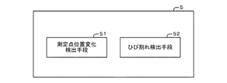
第7の実施形態では、少なくとも2つの測定点における時間的な位置の変化に基づいて構造物6上に発生したひび割れ61を検出するひび割れ検出装置5について説明する。なお、本実施形態では、ひび割れ検出装置5の構成の概要について説明する。
[Seventh Embodiment]
In the seventh embodiment, a crack detection device 5 that detects a crack 61 generated on the structure 6 based on a temporal change in position at at least two measurement points will be described. In the present embodiment, an outline of the configuration of the crack detection device 5 will be described.

図32を参照すると、本実施形態におけるひび割れ検出装置5は、測定点位置変化検出手段51と、ひび割れ検出手段52と、を有している。   Referring to FIG. 32, the crack detection device 5 in this embodiment includes a measurement point position change detection means 51 and a crack detection means 52.

測定点位置変化検出手段51は、構造物6上の少なくとも2つの測定点における時間的な位置の変化を検出する機能を有している。測定点位置変化検出手段51は、上記のように、構造物6上の少なくとも2つの測定点における時間的な位置の変化を検出する。そして、測定点位置変化検出手段51は、検出結果をひび割れ検出手段52に通知する。   The measurement point position change detection means 51 has a function of detecting a temporal position change at at least two measurement points on the structure 6. As described above, the measurement point position change detection unit 51 detects a temporal position change at at least two measurement points on the structure 6. Then, the measurement point position change detection unit 51 notifies the detection result to the crack detection unit 52.

ひび割れ検出手段52は、測定点位置変化検出手段51が検出した各測定点の位置の変化に基づいてひび割れ61を検出する機能を有している。ひび割れ検出手段52は、測定点位置変化検出手段51から検出結果の通知を受信する。そして、ひび割れ検出手段52は、受信した検出結果に基づいてひび割れ61を検出する。   The crack detection means 52 has a function of detecting the crack 61 based on the change in position of each measurement point detected by the measurement point position change detection means 51. The crack detection unit 52 receives the notification of the detection result from the measurement point position change detection unit 51. And the crack detection means 52 detects the crack 61 based on the received detection result.

このように、本実施形態におけるひび割れ検出装置5は、測定点位置変化検出手段51と、ひび割れ検出手段52と、を有している。このような構成により、ひび割れ検出装置5は、測定点位置変化検出手段51による検出結果に基づいてひび割れ61を検出することが出来る。一般に、ひび割れ61の幅は様々な影響を受けて変動する。そのため、測定点の時間的な位置の変化はひび割れ61の幅の変動の影響を受けることになる。一方、画像的に類似している模様などには、そのような特徴はない。そのため、測定点の時間的な位置の変化に基づいてひび割れ61を検出することで、画像的に類似している模様などをひび割れ61として誤検出することなく構造物6表面に現れるひび割れ61を検出することが出来る。   Thus, the crack detection apparatus 5 in this embodiment has the measurement point position change detection means 51 and the crack detection means 52. With such a configuration, the crack detection device 5 can detect the crack 61 based on the detection result by the measurement point position change detection means 51. In general, the width of the crack 61 varies under various influences. Therefore, the change in the temporal position of the measurement point is affected by the fluctuation of the width of the crack 61. On the other hand, there is no such feature in patterns that are similar in image. Therefore, by detecting the crack 61 based on the change in the time position of the measurement point, the crack 61 appearing on the surface of the structure 6 is detected without erroneously detecting a pattern similar to the image as the crack 61. I can do it.

<付記>
上記実施形態の一部又は全部は、以下の付記のようにも記載されうる。以下、本発明におけるひび割れ検出装置などの概略を説明する。但し、本発明は、以下の構成に限定されない。
(付記1)
構造物上のひび割れを検出する情報処理装置であって、
前記構造物上の少なくとも2つの測定点における位置の変化を検出する測定点位置変化検出手段と、
前記測定点位置変化検出手段が検出した前記各測定点の位置の変化に基づいてひび割れを検出するひび割れ検出手段と、
を有する情報処理装置。
(付記2)
前記ひび割れ検出手段は、前記構造物上の2つの測定点の位置の変化の関係性に基づいて、前記2つの測定点の間にひび割れがあることを検出する
付記1に記載の情報処理装置。
(付記3)
前記ひび割れ検出手段は、前記2つの測定点の位置の変化が所定の条件を満たす場合に当該2つの測定点の間にひび割れがあることを検出する
付記2に記載の情報処理装置。
(付記4)
前記ひび割れ検出手段は、前記2つの測定点の位置の変化の関係性と、その周辺の測定点の位置の変化の関係性とに基づいて、前記2つの測定点の間にひび割れがあることを検出する
付記1乃至3の何れかに記載の情報処理装置。
(付記5)
前記測定点の位置の変化に基づいて、前記ひび割れ検出手段が検出したひび割れのひび割れ幅の変動量であるひび割れ幅変動量を算出するひび割れ幅変動量算出手段を有する
付記1乃至4の何れかに記載の情報処理装置。
(付記6)
前記ひび割れ幅変動量算出手段は、前記ひび割れ検出手段が検出したひび割れのひび割れ幅の変動量の最大値を前記ひび割れ幅変動量として算出する
付記5に記載の情報処理装置。
(付記7)
前記ひび割れ幅変動量算出手段が算出した前記ひび割れ幅変動量に基づいて対象の構造物の健全度を評価する第1の健全度評価手段を有する
付記5又は6に記載の情報処理装置。
(付記8)
前記第1の健全度評価手段は、
健全度を評価する基準となる基準ひび割れ幅変動量を記憶する基準ひび割れ幅変動量記憶手段と、
前記ひび割れ幅変動量算出手段が算出した前記ひび割れ幅変動量と前記基準ひび割れ幅変動量記憶手段が記憶する基準ひび割れ幅変動量とを比較するひび割れ幅変動量比較手段と、を含み、
前記ひび割れ幅変動量比較手段による比較結果に基づいて、対象の構造物の健全度を評価する
付記7に記載の情報処理装置。
(付記9)
前記ひび割れ検出手段が検出したひび割れを有する構造物にかかる外力を取得する外力取得手段と、
前記外力取得手段により取得した前記ひび割れ幅変動量算出時の外力と、前記ひび割れ幅変動量と、に基づいて、健全度を評価する際の基準となる外力が印加された際のひび割れ幅変動量である基準外力印加時ひび割れ幅変動量を推定する基準外力印加時ひび割れ幅変動量推定手段と、を有し、
前記第1の健全度評価手段は、前記基準外力印加時ひび割れ幅変動量と前記基準ひび割れ幅変動量との比較結果に基づいて、対象の構造物の健全度を評価する
付記8に記載の情報処理装置。
(付記10)
ひび割れを検出する対象となる構造物を示す画像データを取得する画像データ取得手段と、
前記ひび割れ幅変動量算出手段が算出する前記ひび割れ幅変動量が最大となる際の画像データに基づいて、前記ひび割れ検出手段が検出したひび割れのひび割れ幅を算出するひび割れ幅算出手段と、を有する
請求項5乃至9の何れかに記載の情報処理装置。
(付記11)
前記ひび割れ検出手段が検出したひび割れを有する構造物にかかる外力を取得する外力取得手段と、
前記外力取得手段により取得した前記ひび割れ幅変動量算出時の外力と、前記ひび割れ幅変動量と、に基づいて、前記ひび割れ検出手段が検出したひび割れの深さを算出するひび割れ深さ算出手段と、を有する
付記5乃至10の何れかに記載の情報処理装置。
(付記12)
前記ひび割れ深さ算出手段が算出したひび割れの深さに基づいて対象の構造物の健全度を評価する第2の健全度評価手段を有する
付記11に記載の情報処理装置。
(付記13)
前記第2の健全度評価手段は、前記ひび割れ深さ算出手段が算出したひび割れの深さと、健全度を評価する基準となるひび割れの深さである基準ひび割れ深さと、の比較結果に基づいて対象の構造物の健全度を評価する
付記12に記載の情報処理装置。
(付記14)
前記測定点位置変化検出手段は、前記構造物上の少なくとも2つの測定点における、所定の外力印加前後の位置の変化を検出し、
前記ひび割れ検出手段は、前記所定の外力印加前後の前記構造物上の各測定点の位置の変化に基づいてひび割れを検出する
付記1乃至13の何れかに記載の情報処理装置。
(付記15)
前記測定点位置変化検出手段は、前記測定点の位置の変化として当該測定点の変位方向又は変位量若しくはその両方を検出し、
前記ひび割れ検出手段は、前記測定点位置変化検出手段が検出した各測定点における変位方向又は変位量若しくはその両方に基づいて、ひび割れを検出する
付記1乃至14のいずれかに記載の情報処理装置。
(付記16)
前記測定点位置変化検出手段は、前記測定点の位置の変化に基づいて当該測定点の位置の変化の分布を示す変位分布を算出し、
前記ひび割れ検出手段は、算出した前記変位分布と前記測定点の位置の近さに基づいて前記測定点を複数の領域に分割し、分割した前記複数の領域ごとの位置の変化に基づいて前記複数の領域の境界にひび割れがあることを検出する
付記1乃至15に記載の情報処理装置。
(付記17)
前記ひび割れ検出手段は、変化が所定の条件を満たす領域を1つの領域として前記測定点を複数の領域に分割し、分割した領域の境界にひび割れがあることを検出する
付記16に記載の情報処理装置。
(付記18)
構造物上のひび割れを検出する情報処理方法であって、
前記構造物上の少なくとも2つの測定点における位置の変化を検出し、
検出した前記各測定点の位置の変化に基づいてひび割れを検出する
情報処理方法。
(付記18−1)
前記ひび割れの検出は、前記構造物上の2つの測定点の位置の変化の関係性に基づいて、前記2つの測定点の間にひび割れがあることを検出する
付記18に記載の情報処理方法。
(付記18−2)
前記ひび割れの検出は、前記2つの測定点の位置の変化の関係性と、その周辺の測定点の位置の変化の関係性とに基づいて、前記2つの測定点の間にひび割れがあることを検出する
付記18又は18−1に記載の情報処理方法。
(付記18−3)
前記ひび割れの検出は、前記2つの測定点の位置の変化が所定の条件を満たす場合に当該2つの測定点の間にひび割れがあることを検出する
付記18−2に記載の情報処理方法。
(付記19)
コンピュータを、
前記構造物上の少なくとも2つの測定点における時間的な位置の変化を検出する測定点位置変化検出手段と、
前記測定点位置変化検出手段が検出した前記各測定点の位置の変化に基づいてひび割れを検出するひび割れ検出手段と
して機能させるプログラム。
(付記19−1)
前記ひび割れ検出手段は、前記構造物上の2つの測定点の位置の変化の関係性に基づいて、前記2つの測定点の間にひび割れがあることを検出する
付記19に記載のプログラム。
(付記19−2)
前記ひび割れ検出手段は、前記2つの測定点の位置の変化の関係性と、その周辺の測定点の位置の変化の関係性とに基づいて、前記2つの測定点の間にひび割れがあることを検出する
付記19又は19−1に記載のプログラム。
(付記19−3)
前記ひび割れ検出手段は、前記2つの測定点の位置の変化が所定の条件を満たす場合に当該2つの測定点の間にひび割れがあることを検出する
付記19−2に記載のプログラム。
<Appendix>
Part or all of the above-described embodiment can be described as in the following supplementary notes. Hereinafter, the outline of the crack detection apparatus etc. in this invention is demonstrated. However, the present invention is not limited to the following configuration.
(Appendix 1)
An information processing device for detecting cracks on a structure,
Measuring point position change detecting means for detecting a change in position at least two measuring points on the structure;
Crack detecting means for detecting a crack based on a change in position of each measurement point detected by the measurement point position change detecting means;
An information processing apparatus.
(Appendix 2)
The information processing apparatus according to appendix 1, wherein the crack detection unit detects that there is a crack between the two measurement points based on a relationship between changes in the positions of the two measurement points on the structure.
(Appendix 3)
The information processing apparatus according to appendix 2, wherein the crack detection unit detects that there is a crack between the two measurement points when a change in position of the two measurement points satisfies a predetermined condition.
(Appendix 4)
The crack detection means determines that there is a crack between the two measurement points based on the relationship between the changes in the positions of the two measurement points and the relationship between the changes in the positions of the surrounding measurement points. The information processing apparatus according to any one of supplementary notes 1 to 3 to be detected.
(Appendix 5)
Any one of Supplementary notes 1 to 4, further comprising a crack width fluctuation amount calculating means for calculating a crack width fluctuation amount that is a fluctuation amount of a crack width of the crack detected by the crack detection means based on a change in the position of the measurement point. The information processing apparatus described.
(Appendix 6)
The information processing apparatus according to appendix 5, wherein the crack width fluctuation amount calculating means calculates a maximum value of a crack width fluctuation amount detected by the crack detection means as the crack width fluctuation amount.
(Appendix 7)
The information processing apparatus according to appendix 5 or 6, further comprising first soundness evaluation means for evaluating soundness of the target structure based on the crack width fluctuation amount calculated by the crack width fluctuation amount calculation means.
(Appendix 8)
The first soundness evaluation means includes:
A reference crack width fluctuation amount storage means for storing a reference crack width fluctuation amount as a reference for evaluating the soundness;
A crack width fluctuation amount comparing means for comparing the crack width fluctuation amount calculated by the crack width fluctuation amount calculating means and a reference crack width fluctuation amount stored by the reference crack width fluctuation amount storage means;
The information processing apparatus according to appendix 7, wherein the degree of soundness of the target structure is evaluated based on a comparison result by the crack width fluctuation amount comparison unit.
(Appendix 9)
An external force acquisition means for acquiring an external force applied to a structure having a crack detected by the crack detection means;
Based on the external force at the time of calculation of the crack width fluctuation amount acquired by the external force acquisition means and the crack width fluctuation amount, the crack width fluctuation amount when an external force serving as a reference for evaluating soundness is applied And a crack width fluctuation amount estimating means for applying a reference external force to estimate a crack width fluctuation amount when a reference external force is applied, and
The information according to appendix 8, wherein the first soundness evaluation means evaluates the soundness of the target structure based on a comparison result between the crack width fluctuation amount when the reference external force is applied and the reference crack width fluctuation amount. Processing equipment.
(Appendix 10)
Image data acquisition means for acquiring image data indicating a structure to be detected for cracks;
And a crack width calculating means for calculating a crack width of the crack detected by the crack detecting means based on image data when the crack width fluctuation amount calculated by the crack width fluctuation calculating means is maximum. Item 10. The information processing device according to any one of Items 5 to 9.
(Appendix 11)
An external force acquisition means for acquiring an external force applied to a structure having a crack detected by the crack detection means;
Crack depth calculation means for calculating the crack depth detected by the crack detection means based on the external force at the time of calculation of the crack width fluctuation amount acquired by the external force acquisition means and the crack width fluctuation amount; The information processing apparatus according to any one of appendices 5 to 10 having:
(Appendix 12)
The information processing apparatus according to appendix 11, further comprising second soundness evaluation means for evaluating the soundness of the target structure based on the crack depth calculated by the crack depth calculation means.
(Appendix 13)
The second soundness evaluation means is based on a comparison result between a crack depth calculated by the crack depth calculation means and a reference crack depth that is a crack depth serving as a reference for evaluating soundness. The information processing apparatus according to attachment 12, which evaluates the soundness of the structure of the.
(Appendix 14)
The measurement point position change detecting means detects a change in position before and after applying a predetermined external force at at least two measurement points on the structure,
The information processing apparatus according to any one of appendices 1 to 13, wherein the crack detection unit detects a crack based on a change in position of each measurement point on the structure before and after the predetermined external force is applied.
(Appendix 15)
The measurement point position change detection means detects a displacement direction and / or a displacement amount of the measurement point as a change in the position of the measurement point,
The information processing apparatus according to any one of appendices 1 to 14, wherein the crack detection unit detects a crack based on a displacement direction and / or a displacement amount at each measurement point detected by the measurement point position change detection unit.
(Appendix 16)
The measurement point position change detecting means calculates a displacement distribution indicating a distribution of change in the position of the measurement point based on a change in the position of the measurement point,
The crack detection means divides the measurement point into a plurality of regions based on the calculated displacement distribution and the proximity of the position of the measurement point, and the plurality of the detection points based on a change in position of the divided regions. 16. The information processing device according to any one of supplementary notes 1 to 15, wherein the information processing device detects that there is a crack at a boundary of the region.
(Appendix 17)
The information processing according to supplementary note 16, wherein the crack detecting unit divides the measurement point into a plurality of regions by using a region where the change satisfies a predetermined condition as one region, and detects that there is a crack at the boundary of the divided region apparatus.
(Appendix 18)
An information processing method for detecting cracks on a structure,
Detecting a change in position at at least two measurement points on the structure;
An information processing method for detecting a crack based on a change in the position of each detected measurement point.
(Appendix 18-1)
19. The information processing method according to appendix 18, wherein the detection of the crack is based on a relationship between changes in position of two measurement points on the structure, and detects that there is a crack between the two measurement points.
(Appendix 18-2)
The detection of the crack indicates that there is a crack between the two measurement points based on the relationship between the change in the position of the two measurement points and the relationship between the change in the position of the surrounding measurement points. The information processing method according to appendix 18 or 18-1 to be detected.
(Appendix 18-3)
The detection of the crack is the information processing method according to appendix 18-2, in which when a change in position of the two measurement points satisfies a predetermined condition, it is detected that there is a crack between the two measurement points.
(Appendix 19)
Computer
Measuring point position change detecting means for detecting a temporal position change at at least two measuring points on the structure;
A program that functions as a crack detection unit that detects a crack based on a change in the position of each measurement point detected by the measurement point position change detection unit.
(Appendix 19-1)
The program according to appendix 19, wherein the crack detection means detects that there is a crack between the two measurement points based on the relationship between changes in the positions of the two measurement points on the structure.
(Appendix 19-2)
The crack detection means determines that there is a crack between the two measurement points based on the relationship between the changes in the positions of the two measurement points and the relationship between the changes in the positions of the surrounding measurement points. The program according to appendix 19 or 19-1 to be detected.
(Appendix 19-3)
The program according to appendix 19-2, wherein the crack detection unit detects that there is a crack between the two measurement points when a change in position of the two measurement points satisfies a predetermined condition.

なお、上記各実施形態及び付記において記載したプログラムは、記憶装置に記憶されていたり、コンピュータが読み取り可能な記録媒体に記録されている。例えば、記録媒体は、フレキシブルディスク、光ディスク、光磁気ディスク、及び、半導体メモリ等の可搬性を有する媒体である。   Note that the programs described in the above embodiments and supplementary notes are stored in a storage device or recorded on a computer-readable recording medium. For example, the recording medium is a portable medium such as a flexible disk, an optical disk, a magneto-optical disk, and a semiconductor memory.

以上、上記各実施形態を参照して本願発明を説明したが、本願発明は、上述した実施形態に限定されるものではない。本願発明の構成や詳細には、本願発明の範囲内で当業者が理解しうる様々な変更をすることが出来る。   Although the present invention has been described with reference to the above embodiments, the present invention is not limited to the above-described embodiments. Various changes that can be understood by those skilled in the art can be made to the configuration and details of the present invention within the scope of the present invention.

なお、本発明は、日本国にて2014年4月16日に特許出願された特願2014−085029の特許出願に基づく優先権主張の利益を享受するものであり、当該特許出願に記載された内容は、全て本明細書に含まれるものとする。   In addition, this invention enjoys the benefit of the priority claim based on the patent application of Japanese Patent Application No. 2014-085029 for which it applied for a patent in Japan on April 16, 2014, and was described in the said patent application. The contents are all included in this specification.

1、2 ひび割れ検出装置
11、21、31、41 画像撮影部
12、22、32、42 通信I/F部
13、23、33、43 操作入力部
14、24、34、44 画面表示部
15、25、35、45 記憶部
151、251、351、451 画像情報
152 変化特徴量情報
153、254、357、459 プログラム
16、26、36、46 演算処理部
161、261、361、461 画像取得部
162、262、362、462 変位特徴量算出部
163、264、364、464 ひび割れ検出部
252、352、452 変位分布情報
253、353、453 領域情報
263、363、463 領域分割部
3、4 構造物健全度評価装置
354、454 ひび割れ幅変動量情報
355、455 基準ひび割れ幅変動量情報
356、458 健全度情報
365、465 ひび割れ幅変動量算出部
366、466 ひび割れ幅変動量比較部
367、468 健全度出力部
368 ひび割れ幅算出部
456 外力情報
457 基準外力印加時ひび割れ幅変動量情報
467 基準外力印加時ひび割れ幅変動量算出部
47 外力取得部
5 ひび割れ検出装置
51 測定点位置変化検出手段
52 ひび割れ検出手段
6 構造物
61 ひび割れ
7 ひび割れ深さ評価装置
8 構造物健全度評価装置
71、81 画像撮影部
72、82 通信I/F部
73、83 操作入力部
74、84 画面表示部
75、85 記憶部
751、851 画像情報
752、852 変位分布情報
753、853 領域情報
754、854 ひび割れ幅変動量情報
755、855 ひび割れ深さ情報
856 基準ひび割れ深さ情報
756、857 外力情報
858 健全度情報
757、859 プログラム
76、86 演算処理部
761、861 画像取得部
762、862 変位特徴量算出部
763、863 領域分割部
764、864 ひび割れ検出部
765、865 ひび割れ幅変動量算出部
766、866 ひび割れ深さ算出部
767 ひび割れ深さ出力部
867 ひび割れ深さ比較部
868 健全度出力部

1, 2, Crack detection device 11, 21, 31, 41 Image capturing unit 12, 22, 32, 42 Communication I / F unit 13, 23, 33, 43 Operation input unit 14, 24, 34, 44 Screen display unit 15, 25, 35, 45 Storage unit 151, 251, 351, 451 Image information 152 Change feature amount information 153, 254, 357, 459 Program 16, 26, 36, 46 Arithmetic processing unit 161, 261, 361, 461 Image acquisition unit 162 , 262, 362, 462 Displacement feature amount calculation unit 163, 264, 364, 464 Crack detection unit 252, 352, 452 Displacement distribution information 253, 353, 453 Region information 263, 363, 463 Region division unit 3, 4 Structure sound Degree evaluation device 354, 454 Crack width variation information 355, 455 Reference crack width variation information 356, 458 Sound Information 365, 465 Crack width variation calculation unit 366, 466 Crack width variation comparison unit 367, 468 Soundness output unit 368 Crack width calculation unit 456 External force information 457 Crack width variation information when applying standard external force 467 Crack when standard external force is applied Width variation calculation unit 47 External force acquisition unit 5 Crack detection device 51 Measurement point position change detection unit 52 Crack detection unit 6 Structure 61 Crack 7 Crack depth evaluation device 8 Structure soundness evaluation device 71, 81 Image photographing unit 72, 82 Communication I / F section 73, 83 Operation input section 74, 84 Screen display section 75, 85 Storage section 751, 851 Image information 752, 852 Displacement distribution information 753, 853 Area information 754, 854 Crack width variation information 755, 855 Crack depth information 856 Reference crack depth information 756, 857 External force information 858 Soundness information 757, 859 Program 76, 86 Operation processing unit 761, 861 Image acquisition unit 762, 862 Displacement feature amount calculation unit 763, 863 Region division unit 764, 864 Crack detection unit 765, 865 Crack width variation calculation unit 766, 866 Crack Depth Calculation Unit 767 Crack Depth Output Unit 867 Crack Depth Comparison Unit 868 Soundness Output Unit

Claims (19)

構造物上のひび割れを検出する情報処理装置であって、
前記構造物を撮影した複数の画像から前記構造物上の少なくとも2つの測定点における位置の変化を検出する測定点位置変化検出手段と、
検出した前記測定点それぞれの位置の変化から、前記画像中における変位の分布を算出する変位分布算出手段と、
前記変位の分布に基づいてひび割れを検出するひび割れ検出手段と、
を有する情報処理装置。
An information processing device for detecting cracks on a structure,
Measurement point position change detection means for detecting a change in position at at least two measurement points on the structure from a plurality of images obtained by photographing the structure ;
Displacement distribution calculating means for calculating a distribution of displacement in the image from changes in the positions of the detected measurement points;
Crack detecting means for detecting cracks based on the distribution of the displacement ;
An information processing apparatus.
前記ひび割れ検出手段は、前記2つの測定点の位置の変化の関係性が、変位方向が異なる又は変位量が所定以上の差がある場合に当該2つの測定点の間にひび割れがあることを検出する
請求項1に記載の情報処理装置。
The crack detection means detects that there is a crack between the two measurement points when the relationship between changes in the positions of the two measurement points is different in displacement direction or when the displacement amount is more than a predetermined difference. Do
The information processing apparatus according to claim 1 .
前記変位の分布を示す範囲を、連続的な変位をする領域ごとに分割する領域分割手段をさらに有し、  Further comprising region dividing means for dividing the range indicating the distribution of the displacement for each region where continuous displacement is performed;
前記ひび割れ検出手段は、領域と領域との境界にひび割れを検出する、  The crack detection means detects a crack at a boundary between regions.
請求項1又は2に記載の情報処理装置。The information processing apparatus according to claim 1 or 2.
さらに、前記画像上に検出された前記ひび割れを表示する表示手段を有する、Furthermore, it has display means for displaying the cracks detected on the image,
請求項1乃至3の何れかに記載の情報処理装置。The information processing apparatus according to claim 1.
前記測定点の位置の変化に基づいて、前記ひび割れ検出手段が検出したひび割れのひび割れ幅の変動量であるひび割れ幅変動量を算出するひび割れ幅変動量算出手段を有する
請求項1乃至4の何れかに記載の情報処理装置。
5. The method according to claim 1, further comprising a crack width variation calculation unit that calculates a crack width variation amount, which is a variation amount of a crack width of the crack detected by the crack detection unit, based on a change in the position of the measurement point. The information processing apparatus described in 1.
前記ひび割れ幅変動量算出手段は、前記ひび割れ検出手段が検出したひび割れのひび割れ幅の変動量の最大値を前記ひび割れ幅変動量として算出する
請求項5に記載の情報処理装置。
The information processing apparatus according to claim 5, wherein the crack width fluctuation amount calculating unit calculates a maximum value of a crack width fluctuation amount detected by the crack detection unit as the crack width fluctuation amount.
前記ひび割れ幅変動量算出手段が算出した前記ひび割れ幅変動量に基づいて対象の構造物の健全度を評価する第1の健全度評価手段を有する
請求項5又は6に記載の情報処理装置。
The information processing apparatus according to claim 5, further comprising: a first soundness evaluation unit that evaluates a soundness of a target structure based on the crack width variation calculated by the crack width variation calculation unit.
前記第1の健全度評価手段は、
健全度を評価する基準となる基準ひび割れ幅変動量を記憶する基準ひび割れ幅変動量記憶手段と、
前記ひび割れ幅変動量算出手段が算出した前記ひび割れ幅変動量と前記基準ひび割れ幅変動量記憶手段が記憶する基準ひび割れ幅変動量とを比較するひび割れ幅変動量比較手段と、を含み、
前記ひび割れ幅変動量比較手段による比較結果に基づいて、対象の構造物の健全度を評価する
請求項7に記載の情報処理装置。
The first soundness evaluation means includes:
A reference crack width fluctuation amount storage means for storing a reference crack width fluctuation amount as a reference for evaluating the soundness;
A crack width fluctuation amount comparing means for comparing the crack width fluctuation amount calculated by the crack width fluctuation amount calculating means and a reference crack width fluctuation amount stored by the reference crack width fluctuation amount storage means;
The information processing apparatus according to claim 7, wherein the soundness level of the target structure is evaluated based on a comparison result by the crack width fluctuation amount comparison unit.
前記ひび割れ検出手段が検出したひび割れを有する構造物にかかる外力を取得する外力取得手段と、
前記外力取得手段により取得した前記ひび割れ幅変動量算出時の外力と、前記ひび割れ幅変動量と、に基づいて、健全度を評価する際の基準となる外力が印加された際のひび割れ幅変動量である基準外力印加時ひび割れ幅変動量を推定する基準外力印加時ひび割れ幅変動量推定手段と、を有し、
前記第1の健全度評価手段は、前記基準外力印加時ひび割れ幅変動量と前記基準ひび割れ幅変動量との比較結果に基づいて、対象の構造物の健全度を評価する
請求項8に記載の情報処理装置。
An external force acquisition means for acquiring an external force applied to a structure having a crack detected by the crack detection means;
Based on the external force at the time of calculation of the crack width fluctuation amount acquired by the external force acquisition means and the crack width fluctuation amount, the crack width fluctuation amount when an external force serving as a reference for evaluating soundness is applied And a crack width fluctuation amount estimating means for applying a reference external force to estimate a crack width fluctuation amount when a reference external force is applied, and
The said 1st soundness evaluation means evaluates the soundness of the structure of object based on the comparison result of the crack width fluctuation amount at the time of the said reference external force application, and the said reference crack width fluctuation amount. Information processing device.
ひび割れを検出する対象となる構造物を示す画像データを取得する画像データ取得手段と、
前記ひび割れ幅変動量算出手段が算出する前記ひび割れ幅変動量が最大となる際の画像データに基づいて、前記ひび割れ検出手段が検出したひび割れのひび割れ幅を算出するひび割れ幅算出手段と、を有する
請求項5乃至9の何れかに記載の情報処理装置。
Image data acquisition means for acquiring image data indicating a structure to be detected for cracks;
And a crack width calculating means for calculating a crack width of the crack detected by the crack detecting means based on image data when the crack width fluctuation amount calculated by the crack width fluctuation calculating means is maximum. Item 10. The information processing device according to any one of Items 5 to 9.
前記ひび割れ検出手段が検出したひび割れを有する構造物にかかる外力を取得する外力取得手段と、
前記外力取得手段により取得した前記ひび割れ幅変動量算出時の外力と、前記ひび割れ幅変動量と、に基づいて、前記ひび割れ検出手段が検出したひび割れの深さを算出するひび割れ深さ算出手段と、を有する
請求項5乃至10の何れかに記載の情報処理装置。
An external force acquisition means for acquiring an external force applied to a structure having a crack detected by the crack detection means;
Crack depth calculation means for calculating the crack depth detected by the crack detection means based on the external force at the time of calculation of the crack width fluctuation amount acquired by the external force acquisition means and the crack width fluctuation amount; The information processing apparatus according to claim 5, comprising:
前記ひび割れ深さ算出手段が算出したひび割れの深さに基づいて対象の構造物の健全度を評価する第2の健全度評価手段を有する
請求項11に記載の情報処理装置。
The information processing apparatus according to claim 11, further comprising a second soundness evaluation unit that evaluates the soundness of the target structure based on a crack depth calculated by the crack depth calculation unit.
前記第2の健全度評価手段は、前記ひび割れ深さ算出手段が算出したひび割れの深さと、健全度を評価する基準となるひび割れの深さである基準ひび割れ深さと、の比較結果に基づいて対象の構造物の健全度を評価する
請求項12に記載の情報処理装置。
The second soundness evaluation means is based on a comparison result between a crack depth calculated by the crack depth calculation means and a reference crack depth that is a crack depth serving as a reference for evaluating soundness. The information processing apparatus according to claim 12, wherein the soundness level of the structure is evaluated.
前記測定点位置変化検出手段は、前記構造物上の少なくとも2つの測定点における、所定の外力印加前後の位置の変化を検出し、
前記ひび割れ検出手段は、前記所定の外力印加前後の前記構造物上の各測定点の位置の変化に基づいてひび割れを検出する
請求項1乃至13の何れかに記載の情報処理装置。
The measurement point position change detecting means detects a change in position before and after applying a predetermined external force at at least two measurement points on the structure,
The information processing apparatus according to claim 1, wherein the crack detection means detects a crack based on a change in position of each measurement point on the structure before and after the predetermined external force is applied.
前記測定点位置変化検出手段は、前記測定点の位置の変化として当該測定点の変位方向又は変位量若しくはその両方を検出し、
前記ひび割れ検出手段は、前記測定点位置変化検出手段が検出した各測定点における変位方向又は変位量若しくはその両方に基づいて、ひび割れを検出する
請求項1乃至14のいずれかに記載の情報処理装置。
The measurement point position change detection means detects a displacement direction and / or a displacement amount of the measurement point as a change in the position of the measurement point,
The information processing apparatus according to any one of claims 1 to 14, wherein the crack detection unit detects a crack based on a displacement direction and / or a displacement amount at each measurement point detected by the measurement point position change detection unit. .
前記測定点位置変化検出手段は、前記測定点の位置の変化に基づいて当該測定点の位置の変化の分布を示す変位分布を算出し、
前記ひび割れ検出手段は、算出した前記変位分布と前記測定点の位置の近さに基づいて前記測定点を複数の領域に分割し、分割した前記複数の領域ごとの位置の変化に基づいて前記複数の領域の境界にひび割れがあることを検出する
請求項1乃至15の何れかに記載の情報処理装置。
The measurement point position change detecting means calculates a displacement distribution indicating a distribution of change in the position of the measurement point based on a change in the position of the measurement point,
The crack detection means divides the measurement point into a plurality of regions based on the calculated displacement distribution and the proximity of the position of the measurement point, and the plurality of the detection points based on a change in position for each of the divided regions. Detect that there is a crack at the boundary of the region
The information processing apparatus according to claim 1 .
前記ひび割れ検出手段は、変化が所定の条件を満たす領域を1つの領域として前記測定点を複数の領域に分割し、分割した領域の境界にひび割れがあることを検出する
請求項16に記載の情報処理装置。
The information according to claim 16, wherein the crack detection unit divides the measurement point into a plurality of regions by setting a region where the change satisfies a predetermined condition as one region, and detects that there is a crack at the boundary of the divided region. Processing equipment.
情報処理装置が、構造物上のひび割れを検出する情報処理方法であって、
前記構造物を撮影した複数の画像から前記構造物上の少なくとも2つの測定点における位置の変化を検出し、
検出した前記測定点それぞれの位置の変化から、前記画像中における変位の分布を算出し、
前記変位の分布に基づいてひび割れを検出する
情報処理方法。
An information processing method is an information processing method for detecting cracks on a structure,
Detecting a change in position at least two measurement points on the structure from a plurality of images obtained by photographing the structure ;
From the change in the position of each of the detected measurement points, calculate the distribution of displacement in the image,
An information processing method for detecting a crack based on the distribution of the displacement .
コンピュータを、
構造物を撮影した複数の画像から前記構造物上の少なくとも2つの測定点における位置の変化を検出する測定点位置変化検出手段と、
検出した前記測定点それぞれの位置の変化から、前記画像中における変位の分布を算出する変位分布算出手段と、
前記変位の分布に基づいてひび割れを検出するひび割れ検出手段と
して機能させるプログラム。
Computer
Measurement point position change detection means for detecting a change in position at least two measurement points on the structure from a plurality of images obtained by photographing the structure ;
Displacement distribution calculating means for calculating a distribution of displacement in the image from changes in the positions of the detected measurement points;
A program that functions as a crack detection means for detecting a crack based on the distribution of the displacement .
JP2016513616A 2014-04-16 2015-02-19 Information processing device Active JP6485454B2 (en)

Applications Claiming Priority (3)

Application Number Priority Date Filing Date Title
JP2014085029 2014-04-16
PCT/JP2015/000792 WO2015159469A1 (en) 2014-04-16 2015-02-19 Information processing device

Publications (2)

Publication Number Publication Date
JPWO2015159469A1 JPWO2015159469A1 (en) 2017-04-13
JP6485454B2 true JP6485454B2 (en) 2019-03-20

Family

ID=54323698

Family Applications (1)

Application Number Title Priority Date Filing Date
JP2016513616A Active JP6485454B2 (en) 2014-04-16 2015-02-19 Information processing device

Country Status (3)

Country Link
US (1) US10197502B2 (en)
JP (1) JP6485454B2 (en)
WO (1) WO2015159469A1 (en)

Families Citing this family (21)

* Cited by examiner, † Cited by third party
Publication number Priority date Publication date Assignee Title
WO2017047315A1 (en) * 2015-09-16 2017-03-23 富士フイルム株式会社 Soundness determination device, soundness determination method and soundness determination program
US11107223B2 (en) 2016-03-31 2021-08-31 Nec Corporation Image detection device, image detection method and storage medium storing program
JP6833366B2 (en) * 2016-07-06 2021-02-24 キヤノン株式会社 Information processing device, control method and program of information processing device
JP6687969B2 (en) * 2016-07-28 2020-04-28 公益財団法人鉄道総合技術研究所 Deformation detection device and deformation detection program
US11138711B2 (en) 2016-08-02 2021-10-05 Nec Corporation Degradation detection device, degradation detection method, and computer-readable recording medium
US20180336454A1 (en) * 2017-05-19 2018-11-22 General Electric Company Neural network systems
EP3660786A4 (en) * 2017-07-25 2020-08-05 FUJIFILM Corporation Damage diagram generation method, damage diagram generation device, damage diagram generation system, and recording medium
WO2019054419A1 (en) * 2017-09-12 2019-03-21 日本電気株式会社 State determining device, state determining method, and computer-readable recording medium
US11365963B2 (en) * 2017-09-12 2022-06-21 Nec Corporation State determination apparatus, state determination method, and computer-readable recording medium
WO2019108905A1 (en) * 2017-11-30 2019-06-06 University Of Kansas Fatigue crack detection using feature tracking
KR102075630B1 (en) * 2018-01-16 2020-03-17 주식회사 지오멕스소프트 A measuring method for detecting cracks on the structure surface and the recording medium thereof
WO2019176464A1 (en) * 2018-03-15 2019-09-19 パナソニックIpマネジメント株式会社 Inspection device and inspection method
US11954844B2 (en) * 2018-08-21 2024-04-09 University Of Kansas Fatigue crack detection in civil infrastructure
JP7382604B2 (en) * 2018-09-27 2023-11-17 パナソニックIpマネジメント株式会社 Detection device and detection method
WO2021095166A1 (en) * 2019-11-13 2021-05-20 日本電信電話株式会社 Estimation method, estimation device, and program
JP7396139B2 (en) * 2020-03-18 2023-12-12 セイコーエプソン株式会社 Measurement method, measurement device, measurement system and measurement program
JP7375637B2 (en) * 2020-03-18 2023-11-08 セイコーエプソン株式会社 Measurement method, measurement device, measurement system and measurement program
JP2021147819A (en) 2020-03-18 2021-09-27 セイコーエプソン株式会社 Measurement method, measurement apparatus, measurement system, and measurement program
JP2021148537A (en) 2020-03-18 2021-09-27 セイコーエプソン株式会社 Measuring method, measuring device, measuring system, and measuring program
JP7400566B2 (en) * 2020-03-18 2023-12-19 セイコーエプソン株式会社 Measurement method, measurement device, measurement system and measurement program
CN112229333A (en) * 2020-09-30 2021-01-15 威海华菱光电股份有限公司 Crack change monitoring device and method, storage medium and processor

Family Cites Families (9)

* Cited by examiner, † Cited by third party
Publication number Priority date Publication date Assignee Title
JP2676040B2 (en) * 1989-01-28 1997-11-12 清水建設株式会社 In-plane displacement measurement method for concrete members
JPH11259656A (en) * 1998-03-10 1999-09-24 Teito Rapid Transit Authority Tunnel wall surface decision device
JPH11326225A (en) 1998-05-11 1999-11-26 Hitachi Ltd Method and apparatus for inspecting tubular member
JP2003035528A (en) 2001-07-19 2003-02-07 Ohbayashi Corp System and method for evaluating damage degree of structure by crack image measurement
JP4186117B2 (en) 2004-10-20 2008-11-26 西日本旅客鉄道株式会社 Crack detection method and apparatus
JP4488308B2 (en) 2004-12-08 2010-06-23 株式会社大林組 Method for detecting cracks on the surface of structures
JP3785577B1 (en) * 2004-12-10 2006-06-14 関西ティー・エル・オー株式会社 Crack detection system and crack detection method
US8095324B2 (en) * 2008-06-26 2012-01-10 Pratt & Whitney Canada Corp. Permanent magnet rotor crack detection
JP2011191282A (en) 2010-03-12 2011-09-29 Hironobu Horiuchi Displacement measuring method using moire fringe

Also Published As

Publication number Publication date
JPWO2015159469A1 (en) 2017-04-13
US10197502B2 (en) 2019-02-05
WO2015159469A1 (en) 2015-10-22
US20170038307A1 (en) 2017-02-09

Similar Documents

Publication Publication Date Title
JP6485454B2 (en) Information processing device
Chen et al. Video camera–based vibration measurement for civil infrastructure applications
WO2016047093A1 (en) Status determination device and status determination method
US10371510B2 (en) Structure status determination device, status determination system, and status determination method
US10190992B2 (en) Structure status determination device, status determination system, and status determination method
Hild et al. Digital image correlation: from displacement measurement to identification of elastic properties–a review
Chen et al. Image-based framework for concrete surface crack monitoring and quantification
WO2017179535A1 (en) Structure condition assessing device, condition assessing system, and condition assessing method
JP6954368B2 (en) Displacement component detection device, displacement component detection method, and program
JP6379475B2 (en) Vibration analyzer
Zhong et al. Quasi-optical coherence vibration tomography technique for damage detection in beam-like structures based on auxiliary mass induced frequency shift
Sun et al. Non-contact optical sensing of asphalt mixture deformation using 3D stereo vision
Bai et al. UAV based accurate displacement monitoring through automatic filtering out its camera's translations and rotations
JP6511892B2 (en) State determination apparatus for a structure, state determination system, and state determination method
JP6813025B2 (en) Status determination device, status determination method, and program
Ferrer et al. Targetless image-based method for measuring displacements and strains on concrete surfaces with a consumer camera
Ji A computer vision-based approach for structural displacement measurement
Guindos et al. The utility of low-cost photogrammetry for stiffness analysis and finite-element validation of wood with knots in bending
Shang et al. Multi-point vibration measurement for mode identification of bridge structures using video-based motion magnification
Hosseinzadeh et al. Pixel-based operating modes from surveillance videos for structural vibration monitoring: A preliminary experimental study
CN110532725B (en) Engineering structure mechanical parameter identification method and system based on digital image
Ji et al. A novel image-based approach for structural displacement measurement
JP7156529B2 (en) Displacement measuring device, displacement measuring method, and program
US20200284576A1 (en) State determination apparatus, state determination method, and computer-readable recording medium
JP2019011995A (en) Rigidity measuring device, rigidity measuring method, and program

Legal Events

Date Code Title Description
A621 Written request for application examination

Free format text: JAPANESE INTERMEDIATE CODE: A621

Effective date: 20180115

A131 Notification of reasons for refusal

Free format text: JAPANESE INTERMEDIATE CODE: A131

Effective date: 20181009

A521 Request for written amendment filed

Free format text: JAPANESE INTERMEDIATE CODE: A523

Effective date: 20181206

TRDD Decision of grant or rejection written
A01 Written decision to grant a patent or to grant a registration (utility model)

Free format text: JAPANESE INTERMEDIATE CODE: A01

Effective date: 20190122

A61 First payment of annual fees (during grant procedure)

Free format text: JAPANESE INTERMEDIATE CODE: A61

Effective date: 20190204

R150 Certificate of patent or registration of utility model

Ref document number: 6485454

Country of ref document: JP

Free format text: JAPANESE INTERMEDIATE CODE: R150