JP6484265B2 - Robot system having learning control function and learning control method - Google Patents
Robot system having learning control function and learning control method Download PDFInfo
- Publication number
- JP6484265B2 JP6484265B2 JP2017026317A JP2017026317A JP6484265B2 JP 6484265 B2 JP6484265 B2 JP 6484265B2 JP 2017026317 A JP2017026317 A JP 2017026317A JP 2017026317 A JP2017026317 A JP 2017026317A JP 6484265 B2 JP6484265 B2 JP 6484265B2
- Authority
- JP
- Japan
- Prior art keywords
- robot
- learning
- vibration
- information
- control
- Prior art date
- Legal status (The legal status is an assumption and is not a legal conclusion. Google has not performed a legal analysis and makes no representation as to the accuracy of the status listed.)
- Active
Links
Images


Classifications
-
- B—PERFORMING OPERATIONS; TRANSPORTING
- B25—HAND TOOLS; PORTABLE POWER-DRIVEN TOOLS; MANIPULATORS
- B25J—MANIPULATORS; CHAMBERS PROVIDED WITH MANIPULATION DEVICES
- B25J9/00—Programme-controlled manipulators
- B25J9/16—Programme controls
-
- B—PERFORMING OPERATIONS; TRANSPORTING
- B25—HAND TOOLS; PORTABLE POWER-DRIVEN TOOLS; MANIPULATORS
- B25J—MANIPULATORS; CHAMBERS PROVIDED WITH MANIPULATION DEVICES
- B25J19/00—Accessories fitted to manipulators, e.g. for monitoring, for viewing; Safety devices combined with or specially adapted for use in connection with manipulators
- B25J19/02—Sensing devices
-
- B—PERFORMING OPERATIONS; TRANSPORTING
- B25—HAND TOOLS; PORTABLE POWER-DRIVEN TOOLS; MANIPULATORS
- B25J—MANIPULATORS; CHAMBERS PROVIDED WITH MANIPULATION DEVICES
- B25J9/00—Programme-controlled manipulators
- B25J9/16—Programme controls
- B25J9/1628—Programme controls characterised by the control loop
- B25J9/163—Programme controls characterised by the control loop learning, adaptive, model based, rule based expert control
-
- B—PERFORMING OPERATIONS; TRANSPORTING
- B25—HAND TOOLS; PORTABLE POWER-DRIVEN TOOLS; MANIPULATORS
- B25J—MANIPULATORS; CHAMBERS PROVIDED WITH MANIPULATION DEVICES
- B25J9/00—Programme-controlled manipulators
- B25J9/16—Programme controls
- B25J9/1694—Programme controls characterised by use of sensors other than normal servo-feedback from position, speed or acceleration sensors, perception control, multi-sensor controlled systems, sensor fusion
-
- G—PHYSICS
- G05—CONTROLLING; REGULATING
- G05B—CONTROL OR REGULATING SYSTEMS IN GENERAL; FUNCTIONAL ELEMENTS OF SUCH SYSTEMS; MONITORING OR TESTING ARRANGEMENTS FOR SUCH SYSTEMS OR ELEMENTS
- G05B2219/00—Program-control systems
- G05B2219/30—Nc systems
- G05B2219/39—Robotics, robotics to robotics hand
- G05B2219/39241—Force and vibration control
-
- Y—GENERAL TAGGING OF NEW TECHNOLOGICAL DEVELOPMENTS; GENERAL TAGGING OF CROSS-SECTIONAL TECHNOLOGIES SPANNING OVER SEVERAL SECTIONS OF THE IPC; TECHNICAL SUBJECTS COVERED BY FORMER USPC CROSS-REFERENCE ART COLLECTIONS [XRACs] AND DIGESTS
- Y10—TECHNICAL SUBJECTS COVERED BY FORMER USPC
- Y10S—TECHNICAL SUBJECTS COVERED BY FORMER USPC CROSS-REFERENCE ART COLLECTIONS [XRACs] AND DIGESTS
- Y10S901/00—Robots
- Y10S901/46—Sensing device
Landscapes
- Engineering & Computer Science (AREA)
- Robotics (AREA)
- Mechanical Engineering (AREA)
- Manipulator (AREA)
Description
本発明は、学習制御機能を備えたロボットシステム及び学習制御方法に関する。 The present invention relates to a robot system having a learning control function and a learning control method.
ロボットを使用する生産現場においては、生産効率を向上するために、ロボットの動作を高速化してタクトタイムを短縮することが求められる場合がある。しかし、ロボットの動作をある程度以上高速化すると、減速機の歪みや、ロボットのアーム部自体の剛性不足などに起因して、動作中のロボットの先端の手先部に振動が発生してしまうことがある。 In production sites that use robots, in order to improve production efficiency, it may be required to shorten the tact time by speeding up the operation of the robot. However, if the speed of the robot is increased to some extent, vibration may occur at the tip of the robot that is in operation due to distortion of the reducer or insufficient rigidity of the robot arm itself. is there.
そのような問題の対処法として、従前より、加速度センサをロボットの手先部に取付け、ロボットの動作中の振動を加速度センサにより計測しながら学習制御を繰返し実施することにより該振動を低減させることが行われている(例えば特許文献1参照)。上記の学習制御では、所定の動作プログラムに基づいたロボットの動作中に加速度センサから得られた振動のデータに基づいて該振動を補正するための振動補正量を算出し、該振動補正量を次回の同じ動作プログラムによるサーボ制御に適用するようになされる。 As a countermeasure for such a problem, it is conventionally possible to reduce the vibration by attaching an acceleration sensor to the hand of the robot and repeatedly performing learning control while measuring the vibration during operation of the robot with the acceleration sensor. (For example, refer to Patent Document 1). In the learning control described above, a vibration correction amount for correcting the vibration is calculated based on vibration data obtained from the acceleration sensor during the operation of the robot based on a predetermined operation program, and the vibration correction amount is calculated next time. This is applied to servo control by the same operation program.
ところで、ロボットは、ロボットの使用範囲、すなわち手先部に取付けられたエンドエフェクタの移動範囲によってロボットの姿勢が変わる。ロボットの姿勢が大きく異なる使用範囲どうしでは、ロボットに発生する振動の特性は大きく異なる。
このため、ロボットに対して学習制御を適用する場合には、ロボットの使用範囲が変わっても学習制御により振動を低減できること、いわゆるロバスト性が重要となる。
この点に関し、ロボットの異なる姿勢ごとに周波数応答を測定して、それら全ての姿勢においてロバスト性を確保する学習制御器を設計することが提案されている(例えば特許文献1参照)。
By the way, the posture of the robot changes depending on the use range of the robot, that is, the movement range of the end effector attached to the hand portion. The characteristics of vibration generated in the robot are greatly different between the usage ranges in which the postures of the robot are greatly different.
For this reason, when learning control is applied to a robot, it is important to be able to reduce vibration by learning control even if the range of use of the robot changes, so-called robustness.
In this regard, it has been proposed to design a learning controller that measures the frequency response for each different posture of the robot and ensures robustness in all the postures (see, for example, Patent Document 1).
また、ロボットの使用範囲は把持ハンドや溶接ガンなどのエンドエフェクタの種類によっても変わる可能性がある。この点に関し、学習制御の際に、ロボットに掛かっている負荷に応じてニーラルネットワークのパラメータを切替えることにより正確に振動を推定し、該振動のデータを基に、負荷の変化に対してのロバスト性を確保する方法が提案されている(例えば特許文献2参照)。 In addition, the range of use of the robot may change depending on the type of end effector such as a gripping hand or a welding gun. In this regard, during learning control, the vibration is accurately estimated by switching the parameters of the neural network according to the load applied to the robot, and based on the vibration data, A method of ensuring robustness has been proposed (see, for example, Patent Document 2).
学習制御の対象とするロボットは、学習制御が終了しないと実際の作業を開始することができない。このため、前述のロバスト性だけでなく、できるだけ少ない学習制御の回数で最適な振動補正量を取得することも重要である。しかし、ロボットの姿勢やエンドエフェクタが大きく変わる可能性のあるロボットの広い使用範囲に対して、前述のロバスト性を確保する一つの学習制御器を設計しようとすると、最適な振動補正量を取得するのに必要な学習制御の回数が増加するという問題があった。
そこで、想定されるロボットの使用範囲に対して、学習制御による振動低減効果を保つと共に、学習制御の回数の増加を抑制できることが望まれている。
The robot that is subject to learning control cannot start actual work unless learning control is completed. For this reason, it is important not only to have the robustness described above, but also to obtain an optimal vibration correction amount with as few learning controls as possible. However, when trying to design one learning controller that ensures the robustness described above over a wide range of robot use where the posture and end effector of the robot may change significantly, the optimal vibration correction amount is obtained. There is a problem that the number of learning controls necessary for the increase increases.
Therefore, it is desired that the vibration reduction effect by learning control can be maintained and the increase in the number of times of learning control can be suppressed with respect to the assumed use range of the robot.
本開示の一態様は、ロボットと、該ロボットの動作を制御する動作制御部を有するロボット制御装置と、前記ロボットの制御対象部位に生じる振動を検出するセンサと、を備えたロボットシステムである。前記ロボット制御装置は、前記動作制御部が動作指令により前記ロボットを動作させたときの前記振動を補正するための振動補正量を算出して該振動補正量を次回の前記動作指令に対して適用する学習制御を行う学習制御部を含む。
さらに、一態様のロボットシステムにおいて、前記学習制御部は、
前記ロボットの想定される複数の使用範囲に対してそれぞれ割当てられた、前記振動補正量を算出するための複数の学習制御器と、
前記学習制御の対象とする動作プログラムにより前記ロボットを動作させるときの該ロボットの動作情報に基づいて、前記複数の学習制御器のうちの一つを選択する選択部と、
前記学習制御の実施中に前記センサから得られる前記振動の情報に基づき、前記選択部が選択した前記学習制御器が最適であるか否かを判定する判定部と、
を備えうる。
前記動作情報は、前記ロボットの先端部を移動させる位置の情報と、前記先端部に対してエンドエフェクタが掛ける負荷の情報とを含み、各々の前記使用範囲は、前記ロボットの先端部を移動させる位置の範囲と前記エンドエフェクタに応じた前記負荷の範囲の両方で定義される範囲でありうる。
前記選択した学習制御器が最適でないと前記判定部により判定された場合には、前記選択部は、前記複数の学習制御器のうちの他の学習制御器に切替えうる。
本開示の他の態様は、動作指令に基づいてロボットを動作させて該ロボットの制御対象部位に生じる振動を補正するための振動補正量を算出し、該振動補正量を次回の前記動作指令に対して適用する学習制御を行う、ロボットの学習制御方法である。
さらに、該学習制御方法は、
前記ロボットの想定される複数の使用範囲に対してそれぞれ割当てられた、前記振動補正量を算出するための複数の学習制御器を備えたコンピュータが、前記学習制御の対象とする動作プログラムから前記ロボットの動作情報を取得することと、
前記コンピュータが、前記動作情報に基づいて、前記複数の学習制御器のうちの一つを選択することと、
前記コンピュータが、前記選択された学習制御器により前記学習制御を行うこと、を含みうる。
上記の他の態様の学習制御方法においても、前記動作情報は、前記ロボットの先端部を移動させる位置の情報と、前記先端部に対してエンドエフェクタが掛ける負荷の情報とを含み、各々の前記使用範囲は、前記ロボットの先端部を移動させる位置の範囲と前記エンドエフェクタに応じた前記負荷の範囲の両方で定義される範囲でありうる。
前記ロボットには前記制御対象部位に生じる振動を検出するセンサが取り付けられており、前記コンピュータが、前記学習制御の実施中に前記センサから得られる前記振動の情報に基づいて前記選択した学習制御器が最適であるか否かを判定し、該判定の結果、前記選択した学習制御器が最適でない場合には前記複数の学習制御器のうちの他の学習制御器に切替えることを含みうる。
One aspect of the present disclosure is a robot system including a robot, a robot control device including an operation control unit that controls the operation of the robot, and a sensor that detects vibration generated in a control target portion of the robot. The robot control device calculates a vibration correction amount for correcting the vibration when the operation control unit operates the robot according to an operation command, and applies the vibration correction amount to the next operation command. A learning control unit that performs learning control.
Furthermore, in the robot system according to one aspect, the learning control unit includes:
A plurality of learning controllers, each assigned to a plurality of assumed use ranges of the robot, for calculating the vibration correction amount;
A selection unit that selects one of the plurality of learning controllers based on operation information of the robot when the robot is operated by the operation program to be the target of the learning control;
A determination unit that determines whether or not the learning controller selected by the selection unit is optimal based on the vibration information obtained from the sensor during the execution of the learning control;
Can be provided.
The operation information includes information on a position to move the tip of the robot and information on a load applied by an end effector to the tip, and each of the use ranges moves the tip of the robot. It may be a range defined by both a range of positions and a range of loads depending on the end effector.
When the determination unit determines that the selected learning controller is not optimal, the selection unit can switch to another learning controller among the plurality of learning controllers.
According to another aspect of the present disclosure, a robot is operated based on an operation command to calculate a vibration correction amount for correcting a vibration generated in a control target part of the robot, and the vibration correction amount is used as the next operation command. This is a learning control method for a robot that performs learning control applied to the robot.
Further, the learning control method includes:
A computer comprising a plurality of learning controllers for calculating the vibration correction amount, each assigned to a plurality of assumed use ranges of the robot, from the operation program to be subjected to the learning control, to the robot To obtain the operation information of
The computer selects one of the plurality of learning controllers based on the operation information;
The computer may include performing the learning control by the selected learning controller.
Also in the learning control method of the other aspect described above, the motion information includes information on a position where the tip of the robot is moved and information on a load applied by an end effector to the tip. The use range may be a range defined by both a range of a position where the tip of the robot is moved and a range of the load corresponding to the end effector.
The robot is provided with a sensor for detecting vibrations generated in the control target part, and the computer selects the learning controller selected based on the vibration information obtained from the sensors during the execution of the learning control. Can be switched to another learning controller among the plurality of learning controllers if the selected learning controller is not optimal.
本開示の態様によれば、想定されるロボットの使用範囲に対して、学習制御による振動低減効果を保つと共に、学習制御の回数の増加を抑制することができる。 According to the aspect of the present disclosure, it is possible to maintain the vibration reduction effect by the learning control with respect to the assumed use range of the robot and to suppress the increase in the number of times of the learning control.
添付図面に示される本開示の典型的な実施形態の詳細な説明から、本開示の一態様に係る目的、特徴および利点ならびに他の目的、特徴および利点がさらに明確になるであろう。 The objects, features and advantages of one aspect of the present disclosure and other objects, features and advantages will become more apparent from the detailed description of exemplary embodiments of the present disclosure shown in the accompanying drawings.
次に、本開示の実施形態について図面を参照して説明する。参照する図面において、同様の構成部分または機能部分には同様の参照符号が付けられている。理解を容易にするために、これらの図面は縮尺を適宜変更している。また、図面に示される形態は本発明を実施するための一つの例であり、本発明は図示された形態に限定されるものではない。 Next, an embodiment of the present disclosure will be described with reference to the drawings. In the drawings to be referred to, the same components or functional parts are denoted by the same reference numerals. In order to facilitate understanding, the scales of these drawings are appropriately changed. The form shown in the drawings is an example for carrying out the present invention, and the present invention is not limited to the illustrated form.
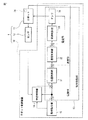
図1は、一実施形態のロボットシステム1を説明するためのブロック図である。図2は、図1に示された学習制御部14の構成例を模式的に示した図である。
図1に示されるように、ロボットシステム1は、ロボット11と、ロボット11と、ロボット11の動作を制御する動作制御部13を有するロボット制御装置10と、ロボット11の制御対象部位に生じる振動を検出するセンサ12と、を備える。
ロボット11は、垂直多関節ロボット、水平多関節ロボット、パラレルリンクロボットなどでありうる。また、上記のロボット11の制御対象部位は、エンドエフェクタを取付可能な、ロボットアーム部の先端の手先部(以降、先端部と呼ぶ場合がある。)でありうる。該エンドエフェクタは、把持ハンド、加工ツール、溶接ガン、レーザ照射装置などである。
FIG. 1 is a block diagram for explaining a
As shown in FIG. 1, the
The
ロボット制御装置10は、動作制御部13が動作指令によりロボット11を動作させたときの該ロボット11の制御対象部位に生じる振動を補正するための振動補正量を算出して該振動補正量を次回の同じ動作指令に対して適用する学習制御を行う学習制御部14をさらに有する。
さらに、ロボット制御装置10は、学習制御の対象とする動作プログラムに基づいて上記の動作指令を生成して動作制御部13に出力するとともに、該動作プログラムに予め記述されているロボット11の動作情報を学習制御部14に出力する動作指令部15を備える。
The
Further, the
ロボット制御装置10はコンピュータシステムである。上記の動作プログラムは、事前のロボットティーチングにより、ロボット制御装置10内のメモリ(不図示)に記憶されている。
動作指令部15には、該メモリに記憶された動作プログラムを読込んで動作指令値を生成するようになされたコンピュータのCPU(control processing unit)が適用できる。このような動作指令部15は、ロボット制御装置10ではなく、ロボット制御装置10に接続された上位コンピュータ(不図示)に設けられていてもよい。また、動作制御部13及び学習制御部14の夫々にもコンピュータが適用されうる。
The
The
図2に示されるように、学習制御部14は、前述の振動補正量を算出するための複数の学習制御器16a〜16dのうちの一つを選択する選択部17を備える。
複数の学習制御器16a〜16dは、ロボット11の想定使用範囲URを分割した複数の使用範囲に対してそれぞれ割当てられている。
選択部17は、前述した学習制御の対象とする動作プログラムによりロボット11を動作させるときの該ロボット11の動作情報に基づいて上記の複数の使用範囲のうちの一つを特定し、複数の学習制御器16a〜16dのうち、該特定した使用範囲に対応する学習制御器を選択するようになされている。
上記のロボット11の動作情報は、ロボット11の先端部を移動させる位置の情報と、該先端部に対してエンドエフェクタが掛ける負荷の情報とを含む。これらの情報は、上記の動作プログラムを基に取得されうる。なお、ロボット11の姿勢はロボット11の先端部(手先部)の位置に応じて変わるので、前述の、ロボット11の先端部を移動させる位置の情報は、動作中のロボット11が取りうる姿勢の情報であるとも言える。
上記複数の使用範囲の各々は、ロボット11の先端部を移動させる位置の範囲と、上記のエンドエフェクタに応じた負荷の範囲の両方で定義される範囲でありうる。
As shown in FIG. 2, the
The plurality of learning
The
The operation information of the
Each of the plurality of use ranges may be a range defined by both a range of positions where the tip of the
図3は、前述したロボット11の想定使用範囲URの一例を示す図である。
例えば、図3に示されるグラフのように、ロボット11の想定使用範囲URは、ロボット11が取りうる姿勢の想定範囲と、エンドエフェクタに応じてロボット11の手先部に掛かる負荷の想定範囲との両方で定義されている。該グラフでは、横軸をロボット姿勢の想定範囲とし、縦軸をそのエンドエフェクタに応じた負荷の想定範囲としている。
想定使用範囲URは、四つの小範囲R1〜R4に分割されている。前述した学習制御器16a〜16dは、四つの小範囲R1〜R4に対してそれぞれ割当てられている。この場合、学習制御部14は、前述したロボット11の動作情報として、ロボット11が取りうる姿勢の情報と、ロボットの11の先端部に対してエンドエフェクタが掛ける負荷の情報との両方を取得するようになっている。
学習制御部14の選択部17は、取得したロボット姿勢の情報とエンドエフェクタによる負荷の情報との両方に基づいて、四つの小範囲R1〜R4のうちの一つを特定し、該特定した小範囲に対応する学習制御器を選択するようになっている。
FIG. 3 is a diagram illustrating an example of the assumed usage range UR of the
For example, as shown in the graph of FIG. 3, the assumed use range UR of the
The assumed use range UR is divided into four small ranges R 1 to R 4 . The
The
より具体的には、ロボット11の動作プログラムには、ロボット11の手先部が始動位置から移動すべき目標位置が記述されている。例えば、ロボット11のアーム部を伸ばしてロボット11の手先部をロボットベース部から遠い範囲だけで移動させる場合のロボット11の姿勢は、ロボット11のアーム部を縮めてロボット11の手先部をロボットベース部に近い範囲だけで移動させる場合のロボット11の姿勢と相異する。このため、動作指令部15は、動作プログラムから、ロボット11の手先部の目標位置の最小値と最大値を抽出し、これらの値を基に、ロボット11の手先部の移動範囲を推定することができる。図3のグラフでは、このようなロボット11の手先部の移動範囲を、ロボット11が取りうる姿勢の範囲としている。
また、ロボット11の動作プログラムには、どのようなエンドエフェクタを使ってロボット11をどのように動作させるかがプログラムされている。例えば、エンドエフェクタとして把持ハンドを使用してワークのピックアンドプレースをロボット11に実行させるような動作プログラムが作成される。あるいは、エンドエフェクタとしてスポット溶接ガンを使用してスポット溶接をロボット11に実行させるような動作プログラムが作成される。ロボット制御装置10は、ロボット11の先端部に装着されうるエンドエフェクタの種類(例えば把持ハンド、スポット溶接ガンなど)ごとの負荷質量のデータをメモリに予め記憶している。動作指令部15は、前述の動作プログラムからエンドエフェクタの種類を特定し、特定したエンドエフェクタに対応する負荷質量のデータを上記メモリからロボット11の動作情報として読みだして学習制御部14に出力することができる。
したがって、前述のように、学習制御部14は、ロボット11の姿勢とエンドエフェクタによる負荷との両方の情報を動作指令部15から取得することができる。
More specifically, the operation program of the
In addition, the operation program of the
Therefore, as described above, the
なお、前述の例は一例に過ぎない。また、ロボット11の想定使用範囲URを四つの小範囲R1〜R4に分割しているが、分割数はこの限りでない。図3のグラフで言うと、横軸で示されるロボット姿勢の範囲を三つの範囲以上に分割してもよい。あるいは、縦軸で示された負荷の範囲を三つの範囲以上に分割してもよい。
Note that the above example is merely an example. Further, although the assumed use range UR of the
さらに、図4は、図3に示された想定使用範囲URに対する追加の例を示す図である。動作プログラムによっては、ロボット11が取りうる姿勢の範囲、すなわちロボット11の先端部の移動範囲が小範囲R1〜R4の各々に収まらないことが有りうる。そこで、図4に示されるように、小範囲R1と小範囲R2の両方に跨る中範囲R5と、小範囲R3と小範囲R4の両方に跨る中範囲R6とを想定し、それら中範囲R5と中範囲R6に対して、前述の振動補正量を算出するための二つの追加の学習制御器をそれぞれ割当ててもよい。このことにより、ロボット制御装置10は、学習制御の対象とする動作プログラムから、小範囲R1〜R4の各々を超えるようなロボット姿勢(即ち、手先部の位置)を取得したとしても、有効な学習制御を実施することができる。
Further, FIG. 4 is a diagram showing an example of addition to the assumed usage range UR shown in FIG. Depending on the operation program, the range of postures that the
図5は、学習制御部14の他の構成例を模式的に示した図である。前述した学習制御部14は、図5に示されるように、学習制御の実施中にセンサ12の検出値、すなわち、ロボット11の制御対象部位に生じる振動の情報に基づき、選択部17が選択した学習制御器が最適であるか否かを判定するようになされた判定部18を備えていてもよい。
ここでいう「学習制御器が最適である」とは、選択された学習制御器により、上記の制御対象部位における振動が低減したことを意味する。
さらに、図5に示された他の構成例の場合は、選択部17が選択した学習制御器が最適でないと判定部18により判定されると、選択部17は、複数の学習制御器16a〜16dのうちの他の学習制御器に切替えるようになっている。選択部17は、選択した学習制御器が最適であると判定部18により判定されるまで、学習制御器の切替えを行うことができる。
FIG. 5 is a diagram schematically illustrating another configuration example of the
Here, “the learning controller is optimal” means that the vibration at the control target part is reduced by the selected learning controller.
Furthermore, in the case of the other configuration example shown in FIG. 5, if the
図6は、前述したロボット制御装置10によって行われる処理フローの一例を示すフローチャートである。図6に示される処理フローは本開示のロボット制御方法の一例である。図6に示される処理フローを実行するロボット制御装置10はデジタルコンピュータであるものとする。
FIG. 6 is a flowchart illustrating an example of a processing flow performed by the
先ず、図6のステップS11において、ロボット制御装置10は、学習制御の対象とする動作プログラムからロボット11の動作情報を取得する。
次のステップS12において、ロボット制御装置10は、取得した動作情報に基づいて、ロボット11の想定使用範囲URを分割した複数の小範囲R1〜R4のうちの一つを特定し、複数の学習制御器16a〜16dのうち、該特定した小範囲に対応する学習制御器を選択する。
次のステップS13において、ロボット制御装置10は、選択された学習制御器により学習制御を実施する。
First, in step S <b> 11 of FIG. 6, the
In the next step S12, the
In the next step S13, the
次のステップS14において、ロボット制御装置10は、センサ12の検出値、すなわちロボット11に生じる振動の情報に基づき、選択された学習制御器が最適であるか否かを判定する。
上記ステップS14での判定結果において、選択された学習制御器が最適でない場合には、ロボット制御装置10は、複数の学習制御器16a〜16dのうちの他の学習制御器に切替える(ステップS15)。さらに、ロボット制御装置10は、選択された学習制御器が最適であると判定するまで、上記のステップS13〜ステップS15を繰返す。
一方、上記ステップS14での判定結果において、選択された学習制御器が最適である場合には、ロボット制御装置10は、選択された学習制御器によって学習制御を所定の回数だけ繰返し実施して(ステップS16)、学習制御を終了する。
In the next step S <b> 14, the
If the selected learning controller is not optimal in the determination result in step S14, the
On the other hand, if the selected learning controller is optimal in the determination result in step S14, the
さらに、一実施形態のロボットシステム1について、具体的に説明する。
図7は、前述したロボットシステム1に適用可能なロボット11の一例を示す図である。図8は、図7に示されたロボット11の構成要素と座標系とを説明するための図である。
本実施形態のロボット11は、図7に示されるような六軸の垂直多関節ロボットである。ロボット11は、図8に示されているように、六つの関節軸11b1〜11b6と、関節軸11b1〜11b6の各々により連結されたアーム部11aと、関節軸11b1〜11b6の各々を駆動するサーボモータ(不図示)とを具備する。勿論、ロボット11の形態は、図1に示された形態に限られず、水平多関節ロボットやパラレルリンクロボットなどであってもよい。
上述したセンサ12は、ロボット11の先端部19に設けられたエンドエフェクタ20に取付けられている。このことにより、本実施形態のセンサ12は、ロボット11の制御対象部位である先端部19に生じる振動を検出する。センサ12はロボット11に対して着脱自在である。エンドエフェクタ20としてはツール部、ハンド部、ボルト締め具、溶接ガンなどを使用することができる。
Furthermore, the
FIG. 7 is a diagram illustrating an example of the
The
The
ロボット11は、図8に示されるように、空間上に固定されたワールド座標系21と、ロボット11の手首部の先端のフランジに設定されたメカニカルインタフェイス座標系22とを有する。ワールド座標系21とメカニカルインタフェイス座標系22とはそれぞれ3次元直交座標系である。
なお、ワールド座標系21及びメカニカルインタフェイス座標系22の各々について、便宜上、図8の中に拡大図によって示した。ワールド座標系21においては、図8の右方向に+X軸、図8の上方向に+Z軸、図8の紙面に対して奥行方向に+Y軸をそれぞれ定義している。メカニカルインタフェイス座標系22においては、図8の右方向に+X軸、図8の下方向に+Z軸、図8の紙面に対して手前方向に+Y軸をそれぞれ定義している。本実施形態においては、事前にキャリブレーションによってワールド座標系21とメカニカルインタフェイス座標系22との位置の相関がとられている。このことにより、ロボット制御装置10動作制御部13は、ワールド座標系21で定義される位置を用いて、エンドエフェクタ20が取付けられたロボット11の先端部19の位置を制御することができる。
As shown in FIG. 8, the
The world coordinate
本実施形態のロボット制御装置10は、図7に示されるようにロボット11とケーブル23を介して互いに接続されている。センサ12は、ケーブルまたは無線通信によってロボット制御装置10と通信可能に接続されている。
本実施形態のセンサ12としては加速度センサが使用されているが、使用可能なセンサ12は加速度センサに限定されない。また、本実施形態のセンサ12はロボット11の先端部19に設置されているが、センサ12の設置場所も限定されない。つまり、ロボット11の制御対象部位に生じる振動を検出できるのであれば、センサ12の種類や設置場所は問わない。ロボット11から離された場所にセンサ12が設置されていてもよい。このため、使用可能なセンサ12としては、例えば、ジャイロセンサ、慣性センサ、力センサ、レーザトラッカ、カメラ、またはモーションキャプチャ装置などがありうる。これらの装置はいずれも、或る位置の経時変化を計測できるため、計測された位置における振動量を検出することができる。
例えば、加速度センサの場合は、ロボット11の制御対象部位における加速度を2回積分すれば位置を算出できるため、算出した位置の変化から振動量を検出することができる。力センサの場合は、制御対象部位に発生したトルクまたはモーメントから、その対象部位の最初の位置からの回転角を求め、該回転角を基にその対象部位の変位量、すなわち振動量を算出することができる。
The
Although the acceleration sensor is used as the
For example, in the case of an acceleration sensor, since the position can be calculated by integrating the acceleration in the control target part of the
ここで、再び図1を参照すると、ロボット11はサーボモータ24により駆動される。サーボモータ24は、位置フィードバック値(以下、位置FBと呼ぶ。)及び速度フィードバック値(以下、速度FBと呼ぶ。)を検出するパルスコーダ(不図示)を内蔵している。
Here, referring to FIG. 1 again, the
図1に示された動作指令部15は、予め作成された動作プログラムに基づいて、ロボットを動作させる動作指令を生成して動作制御部13に対して出力する。動作プログラムは、ロボット制御装置10内のROM等のメモリに記憶されている。また、動作指令部15は、上記の動作プログラムに予め記述されているロボット11の動作情報を学習制御部14に出力する。
The
さらに、ロボット制御装置10の動作制御部13は、位置制御部31、速度制御部32、電流制御部33、及びアンプ34を備える。
位置制御部31は、動作指令部15から動作指令として与えられた位置指令値と、サーボモータ24が出力した位置FBとの差である第一位置偏差量を処理し、速度制御部32に対して速度指令値を出力する。
速度制御部32は、位置制御部31から与えられた速度指令値と、サーボモータ24が出力した速度FBとの差である速度偏差量を処理し、電流制御部33に対して電流指令値を出力する。
電流制御部33は、速度制御部32から与えられた電流指令値と、アンプ34からの電流FB(即ち、電流フィードバック値)との差である電流偏差量を処理し、アンプ34に対して電流指令値(トルク指令値)を出力する。
アンプ34は、電流制御部33からそれぞれ電流指令値を受信するとともに、受信した電流指令値に基づいて、サーボモータ24を駆動する駆動電流を生成し、サーボモータ24を回転駆動する。
動作指令部15からの動作指令に従って、ロボット11の関節軸11b1〜11b6の各々に連結されたサーボモータ24を回転駆動させると、エンドエフェクタ20が取付けられたロボット11の先端部19は、指令された位置に移動する。
Furthermore, the
The
The
The
The
When the
センサ12は、動作制御部13が動作指令に基づいてロボット11の動作制御を行った間にロボット11の先端部19に生じる振動を検出する。センサ12の検出値は学習制御器14に入力されるようになっている(図2参照)。
学習制御部14は、いわゆる学習制御を行うための機能部分である。具体的には、動作指令部15は、所定の制御周期で同じ動作指令値を動作制御部13に繰返し出力する。動作制御部13は、該動作指令値によりロボット11の動作を制御しつつ、制御周期毎に同じ動作指令値を学習制御部14にも出力する。学習制御部14は、同じ動作指令値の入力の度に、上記の先端部19に生じる振動を補正するための振動補正量を算出して該振動補正量を次回の同じ動作指令によるロボット11の動作制御に適用する学習制御を行う。学習制御部14は、このような学習制御を繰返すことにより、ロボット11の先端部19に生じる振動を低減させる。
The
The
例えば生産現場において、ロボットオペレータは、ロボット11を動作プログラムにより実稼働させる前に、実稼働時と同じ動作プログラムを使ってロボット制御装置10に繰返しの学習制御を実行させる。繰返しの学習制御により、ロボット11の先端部19の振動が十分に低減できたら、最後に算出された振動補正量がロボット制御装置10内のメモリに保存される。保存された振動補正量は、生産現場でロボット11を上記の動作プログラムにより実稼働させる際に使用されることになる。
振動補正量を算出するためにセンサ12が使用されるが、学習制御の終了後には、センサ12はロボット11の先端部19のエンドエフェクタ20から取外される。
For example, at the production site, the robot operator causes the
Although the
また、振動補正量を算出するのに必要となる振動量データは、動作指令部15から学習制御部14に入力される動作指令値と、学習制御部14に入力されるセンサ12の検出値との差である第二位置偏差量を所定の制御周期毎に演算処理することで得られる。さらに、振動補正量は、得られた振動データの近似式を推定し、推定した近似式を逆変換することにより算出されうる。言い換えれば、振動補正量は、時系列の振動量データをゼロ付近に補正するための関数である。
The vibration amount data necessary for calculating the vibration correction amount includes an operation command value input from the
既に説明したように、上記の振動補正量を求めるための複数の学習制御器16a〜16dが学習制御部14に設けられている(図2、図5参照)。本実施形態の学習制御部14は、上述したように学習制御を実行するときに、ロボット11の動作情報に基づいて複数の学習制御器16a〜16dのうちの一つを選択する選択部17を備えている。複数の学習制御器16a〜16dは、ロボット11の想定使用範囲URを分割した複数の小範囲R1〜R4(図3参照)に対してそれぞれ割当てられている。
ロボット11が六軸の垂直多関節ロボット(図7、図8参照)である場合には、ロボット11の動作情報は、ワールド座標系21で定義されるロボット11の先端部19の目標位置から得られるロボット姿勢の情報と、ロボット11の先端部19に対してエンドエフェクタ20が掛ける負荷の情報の両方である。該ロボット姿勢の情報は先端部19の移動範囲の情報に相当し、この先端部19の位置は、ワールド座標系21の原点を基準としたメカニカルインタフェイス座標系22の原点の位置とすることができる。このようなロボット11の姿勢と負荷の両方の情報に基づいて、選択部17は、複数の小範囲R1〜R4のうちの一つを特定し、該特定した小範囲に対応する学習制御器を選択するようになっている。
As already described, a plurality of learning
When the
以上に説明したようなロボットシステム1によれば、学習制御の対象プログラムによりロボット11を動作させるときのロボット11の動作情報に基づいて、ロボット11の想定使用範囲URを分割した複数の小範囲R1〜R4のうちの一つに合った学習制御器が選択されるようにしている。このことにより、ロボット11の想定使用範囲URに対して、学習制御による振動低減効果を保ちつつ、学習制御の回数の増加を抑制することができる。
According to the
さらに言えば、ロボット11の姿勢やエンドエフェクタ20が大きく変わる可能性のあるロボット11の広い使用範囲に対して単一の学習制御器を設計する場合と比べて、本実施形態の場合には、個々の学習制御器に要求されるロバスト性は低くなる。したがって、本実施形態のように、ロボット11の広い使用範囲を分割した複数の小範囲の夫々に対して学習制御器を割当てておく方が、比較的少ない学習制御の回数で最適な振動補正量を取得することができる。
Furthermore, in the case of this embodiment, compared with the case where a single learning controller is designed for a wide range of use of the
以上、典型的な実施形態を用いて本発明を説明したが、当業者であれば、本発明の範囲から逸脱することなしに、上述の実施形態のロボットシステム及びロボット制御装置の各々の構成要素や機能などに変更および種々の他の変更、省略、追加を行うことができるのを理解できるであろう。 Although the present invention has been described above using typical embodiments, those skilled in the art will understand the components of each of the robot system and the robot control device according to the above-described embodiments without departing from the scope of the present invention. It will be understood that changes and various other changes, omissions, and additions can be made to and functions.
1 ロボットシステム
10 ロボット制御装置
11 ロボット
12 センサ
13 動作制御部
14 学習制御部
15 動作指令部
16a〜16d 学習制御器
17 選択部
18 判定部
19 ロボットの先端部
20 エンドエフェクタ
21 ワールド座標系
22 メカニカルインタフェイス座標系
23 ケーブル
24 サーボモータ
31 位置制御部
32 速度制御部
33 電流制御部
34 アンプ
DESCRIPTION OF
Claims (6)
前記ロボット制御装置は、前記動作制御部が動作指令により前記ロボットを動作させたときの前記振動を補正するための振動補正量を算出して該振動補正量を次回の前記動作指令に対して適用する学習制御を行う学習制御部を含み、
前記学習制御部は、
前記ロボットの想定される複数の使用範囲に対してそれぞれ割当てられた、前記振動補正量を算出するための複数の学習制御器と、
前記学習制御の対象とする動作プログラムにより前記ロボットを動作させるときの該ロボットの動作情報に基づいて、前記複数の学習制御器のうちの一つを選択する選択部と、
前記学習制御の実施中に前記センサから得られる前記振動の情報に基づき、前記選択部が選択した前記学習制御器が最適であるか否かを判定する判定部と、
を備え、
前記動作情報は、前記ロボットの先端部を移動させる位置の情報と、前記先端部に対してエンドエフェクタが掛ける負荷の情報とを含み、
各々の前記使用範囲は、前記ロボットの先端部を移動させる位置の範囲と前記エンドエフェクタに応じた前記負荷の範囲の両方で定義される範囲であり、
前記選択した学習制御器が最適でないと前記判定部により判定された場合には、前記選択部は、前記複数の学習制御器のうちの他の学習制御器に切替える、ロボットシステム。 A robot system comprising: a robot; a robot control apparatus having an operation control unit that controls the operation of the robot; and a sensor that detects vibration generated in a control target part of the robot,
The robot control device calculates a vibration correction amount for correcting the vibration when the operation control unit operates the robot according to an operation command, and applies the vibration correction amount to the next operation command. Including a learning control unit for performing learning control,
The learning control unit
A plurality of learning controllers, each assigned to a plurality of assumed use ranges of the robot, for calculating the vibration correction amount;
A selection unit that selects one of the plurality of learning controllers based on operation information of the robot when the robot is operated by the operation program to be the target of the learning control;
A determination unit that determines whether or not the learning controller selected by the selection unit is optimal based on the vibration information obtained from the sensor during the execution of the learning control;
With
The operation information includes information on a position for moving the tip of the robot, and information on a load applied by an end effector to the tip.
The range of use of each of Ri ranges der defined in both ranges of the load corresponding to the range and the end effector position for moving the tip of the robot,
The robot system , wherein when the determination unit determines that the selected learning controller is not optimal, the selection unit switches to another learning controller among the plurality of learning controllers .
前記ロボットの想定される複数の使用範囲に対してそれぞれ割当てられた、前記振動補正量を算出するための複数の学習制御器を備えたコンピュータが、前記学習制御の対象とする動作プログラムから前記ロボットの動作情報を取得することと、
前記コンピュータが、前記動作情報に基づいて、前記複数の学習制御器のうちの一つを選択することと、
前記コンピュータが、前記選択された学習制御器により前記学習制御を行うこと、を含み、
前記動作情報は、前記ロボットの先端部を移動させる位置の情報と、前記先端部に対してエンドエフェクタが掛ける負荷の情報とを含み、
各々の前記使用範囲は、前記ロボットの先端部を移動させる位置の範囲と前記エンドエフェクタに応じた前記負荷の範囲の両方で定義される範囲であり、
前記ロボットには前記制御対象部位に生じる振動を検出するセンサが取り付けられており、
前記コンピュータが、前記学習制御の実施中に前記センサから得られる前記振動の情報に基づいて前記選択した学習制御器が最適であるか否かを判定し、該判定の結果、前記選択した学習制御器が最適でない場合には前記複数の学習制御器のうちの他の学習制御器に切替えることを含む、ロボットの学習制御方法。 Based on the motion command, the robot is operated to calculate a vibration correction amount for correcting the vibration generated in the control target part of the robot, and learning control is performed to apply the vibration correction amount to the next motion command. A learning control method for a robot,
A computer comprising a plurality of learning controllers for calculating the vibration correction amount, each assigned to a plurality of assumed use ranges of the robot, from the operation program to be subjected to the learning control, to the robot To obtain the operation information of
The computer selects one of the plurality of learning controllers based on the operation information;
The computer performing the learning control with the selected learning controller;
The operation information includes information on a position for moving the tip of the robot, and information on a load applied by an end effector to the tip.
The range of use of each of Ri ranges der defined in both ranges of the load corresponding to the range and the end effector position for moving the tip of the robot,
The robot is equipped with a sensor for detecting vibrations generated in the control target part,
The computer determines whether or not the selected learning controller is optimal based on the vibration information obtained from the sensor during the execution of the learning control, and the selected learning control is determined as a result of the determination. A learning control method for a robot, comprising switching to another learning controller among the plurality of learning controllers when the apparatus is not optimal .
Priority Applications (4)
| Application Number | Priority Date | Filing Date | Title |
|---|---|---|---|
| JP2017026317A JP6484265B2 (en) | 2017-02-15 | 2017-02-15 | Robot system having learning control function and learning control method |
| DE102018001026.1A DE102018001026B4 (en) | 2017-02-15 | 2018-02-08 | Robot system with a learning control function and a learning control method |
| US15/892,990 US10618164B2 (en) | 2017-02-15 | 2018-02-09 | Robot system having learning control function and learning control method |
| CN201810151988.XA CN108422420B (en) | 2017-02-15 | 2018-02-14 | Robot system having learning control function and learning control method |
Applications Claiming Priority (1)
| Application Number | Priority Date | Filing Date | Title |
|---|---|---|---|
| JP2017026317A JP6484265B2 (en) | 2017-02-15 | 2017-02-15 | Robot system having learning control function and learning control method |
Publications (2)
| Publication Number | Publication Date |
|---|---|
| JP2018130800A JP2018130800A (en) | 2018-08-23 |
| JP6484265B2 true JP6484265B2 (en) | 2019-03-13 |
Family
ID=62982763
Family Applications (1)
| Application Number | Title | Priority Date | Filing Date |
|---|---|---|---|
| JP2017026317A Active JP6484265B2 (en) | 2017-02-15 | 2017-02-15 | Robot system having learning control function and learning control method |
Country Status (4)
| Country | Link |
|---|---|
| US (1) | US10618164B2 (en) |
| JP (1) | JP6484265B2 (en) |
| CN (1) | CN108422420B (en) |
| DE (1) | DE102018001026B4 (en) |
Families Citing this family (13)
| Publication number | Priority date | Publication date | Assignee | Title |
|---|---|---|---|---|
| JP6669715B2 (en) * | 2017-11-30 | 2020-03-18 | ファナック株式会社 | Vibration suppressor |
| JP6705851B2 (en) | 2018-02-22 | 2020-06-03 | ファナック株式会社 | Vibration analysis device and vibration analysis method |
| JP7034035B2 (en) * | 2018-08-23 | 2022-03-11 | 株式会社日立製作所 | Motion generation method for autonomous learning robot device and autonomous learning robot device |
| JP7164368B2 (en) * | 2018-09-14 | 2022-11-01 | ファナック株式会社 | robot equipment |
| DE102019006725B4 (en) * | 2018-10-02 | 2023-06-01 | Fanuc Corporation | control device and control system |
| JP6836571B2 (en) * | 2018-11-14 | 2021-03-03 | ファナック株式会社 | Robot device |
| US11597083B2 (en) * | 2018-12-17 | 2023-03-07 | Canon Kabushiki Kaisha | Robot apparatus, robot system, control method of robot apparatus, product manufacturing method using robot apparatus, and storage medium |
| WO2020161880A1 (en) * | 2019-02-08 | 2020-08-13 | 日本電気株式会社 | Motion model calculation device, control device, joint mechanism, motion model calculation method, and recording medium storing program |
| JP7000371B2 (en) * | 2019-03-22 | 2022-01-19 | ファナック株式会社 | Machine learning equipment, control systems and machine learning methods |
| JP7294883B2 (en) | 2019-05-27 | 2023-06-20 | ファナック株式会社 | CONTROL DEVICE, MACHINE SYSTEM, AND TIME SYNCHRONIZATION METHOD |
| DE102019213676B3 (en) * | 2019-09-10 | 2020-09-17 | Kuka Deutschland Gmbh | Robot control |
| EP3792141A1 (en) * | 2019-09-13 | 2021-03-17 | Nabtesco Corporation | Railway condition monitoring device |
| DE102021209867A1 (en) | 2021-09-07 | 2023-03-09 | Kuka Deutschland Gmbh | Assessing and/or controlling a robotic work process |
Family Cites Families (36)
| Publication number | Priority date | Publication date | Assignee | Title |
|---|---|---|---|---|
| JPH0588721A (en) * | 1991-09-30 | 1993-04-09 | Fujitsu Ltd | Controller for articulated robot |
| JPH07314360A (en) * | 1994-05-31 | 1995-12-05 | Ishikawajima Harima Heavy Ind Co Ltd | Camera operating robot |
| JPH10111701A (en) * | 1996-10-05 | 1998-04-28 | Ricoh Co Ltd | Learning-type automatic cell device and learning method |
| JP2003084804A (en) * | 2001-09-10 | 2003-03-19 | Yaskawa Electric Corp | Optimum command forming unit |
| JP4587738B2 (en) * | 2003-08-25 | 2010-11-24 | ソニー株式会社 | Robot apparatus and robot posture control method |
| JP2005153047A (en) * | 2003-11-21 | 2005-06-16 | Fanuc Ltd | Joint device of robot |
| JP2006110702A (en) * | 2004-10-18 | 2006-04-27 | Fanuc Ltd | Robot having learning control function, and method for controlling robot |
| JP4850956B2 (en) * | 2010-02-19 | 2012-01-11 | ファナック株式会社 | Robot with learning control function |
| JP2012232370A (en) * | 2011-04-28 | 2012-11-29 | Seiko Epson Corp | Robot controller, simplified installation type robot, and method of controlling simplified installation type robot |
| US8886359B2 (en) | 2011-05-17 | 2014-11-11 | Fanuc Corporation | Robot and spot welding robot with learning control function |
| JP5727865B2 (en) * | 2011-05-23 | 2015-06-03 | 東芝三菱電機産業システム株式会社 | Rolling model optimization device |
| JP5438175B2 (en) * | 2012-07-09 | 2014-03-12 | ファナック株式会社 | Vibration control robot system |
| JP6347595B2 (en) * | 2013-11-25 | 2018-06-27 | キヤノン株式会社 | Robot control method and robot control apparatus |
| JP5815664B2 (en) * | 2013-12-26 | 2015-11-17 | ファナック株式会社 | Robot system with wireless acceleration sensor |
| CN104325268A (en) * | 2014-11-04 | 2015-02-04 | 南京赫曼机器人自动化有限公司 | Industrial robot three-dimensional space independent assembly method based on intelligent learning |
| CN105729441A (en) * | 2014-12-24 | 2016-07-06 | 精工爱普生株式会社 | Robot, robot system, control apparatus, and control method |
| JP6333795B2 (en) * | 2015-11-24 | 2018-05-30 | ファナック株式会社 | Robot system with simplified teaching and learning performance improvement function by learning |
| JP6514166B2 (en) * | 2016-09-16 | 2019-05-15 | ファナック株式会社 | Machine learning apparatus, robot system and machine learning method for learning robot operation program |
| JP6514171B2 (en) * | 2016-09-27 | 2019-05-15 | ファナック株式会社 | Machine learning apparatus and method for learning an optimal article gripping path |
| JP6400750B2 (en) * | 2017-01-26 | 2018-10-03 | ファナック株式会社 | Control system having learning control function and control method |
| JP6502976B2 (en) * | 2017-02-15 | 2019-04-17 | ファナック株式会社 | Numerical control device |
| JP6426781B2 (en) * | 2017-03-08 | 2018-11-21 | ファナック株式会社 | Mechanical system |
| JP2018171664A (en) * | 2017-03-31 | 2018-11-08 | セイコーエプソン株式会社 | Control device, robot and robot system |
| JP6870433B2 (en) * | 2017-03-31 | 2021-05-12 | セイコーエプソン株式会社 | Control device and robot system |
| JP6939024B2 (en) * | 2017-03-31 | 2021-09-22 | セイコーエプソン株式会社 | Robot control devices, robots and robot systems |
| JP6557285B2 (en) * | 2017-05-26 | 2019-08-07 | ファナック株式会社 | Control device and machine learning device |
| JP6585666B2 (en) * | 2017-07-03 | 2019-10-02 | ファナック株式会社 | Robot for performing learning control in an application that requires constant speed and its control method |
| JP6564426B2 (en) * | 2017-07-07 | 2019-08-21 | ファナック株式会社 | Parts supply device and machine learning device |
| JP6564433B2 (en) * | 2017-08-29 | 2019-08-21 | ファナック株式会社 | Robot system |
| JP6581162B2 (en) * | 2017-09-29 | 2019-09-25 | ファナック株式会社 | Processing system and processing machine control method |
| JP6669715B2 (en) * | 2017-11-30 | 2020-03-18 | ファナック株式会社 | Vibration suppressor |
| US11221611B2 (en) * | 2018-01-24 | 2022-01-11 | Milwaukee Electric Tool Corporation | Power tool including a machine learning block |
| US11872698B2 (en) * | 2018-02-13 | 2024-01-16 | Canon Kabushiki Kaisha | Controller of robot and control method |
| WO2019161212A1 (en) * | 2018-02-15 | 2019-08-22 | Amsted Rail Company, Inc. | System, method and apparatus for monitoring the health of railcar wheelsets |
| JP6705851B2 (en) * | 2018-02-22 | 2020-06-03 | ファナック株式会社 | Vibration analysis device and vibration analysis method |
| JP6698733B2 (en) * | 2018-04-06 | 2020-05-27 | ファナック株式会社 | Robot system for learning control using motor encoder and sensor |
-
2017
- 2017-02-15 JP JP2017026317A patent/JP6484265B2/en active Active
-
2018
- 2018-02-08 DE DE102018001026.1A patent/DE102018001026B4/en active Active
- 2018-02-09 US US15/892,990 patent/US10618164B2/en active Active
- 2018-02-14 CN CN201810151988.XA patent/CN108422420B/en active Active
Also Published As
| Publication number | Publication date |
|---|---|
| US10618164B2 (en) | 2020-04-14 |
| DE102018001026A1 (en) | 2018-08-16 |
| US20180229364A1 (en) | 2018-08-16 |
| CN108422420A (en) | 2018-08-21 |
| JP2018130800A (en) | 2018-08-23 |
| CN108422420B (en) | 2020-04-10 |
| DE102018001026B4 (en) | 2020-11-19 |
Similar Documents
| Publication | Publication Date | Title |
|---|---|---|
| JP6484265B2 (en) | Robot system having learning control function and learning control method | |
| JP6400750B2 (en) | Control system having learning control function and control method | |
| US10350749B2 (en) | Robot control device having learning control function | |
| JP5480198B2 (en) | Spot welding robot with learning control function | |
| JP5327722B2 (en) | Robot load estimation apparatus and load estimation method | |
| JP7122821B2 (en) | Robot system and robot control method | |
| JP5849451B2 (en) | Robot failure detection method, control device, and robot | |
| US9555548B2 (en) | Robot control device for controlling robot moved according to applied force | |
| JPWO2011161765A1 (en) | Robot controller | |
| JP5916583B2 (en) | Weaving control device for articulated robot | |
| JP6044511B2 (en) | Robot control method and robot system | |
| JP6705851B2 (en) | Vibration analysis device and vibration analysis method | |
| JP2006215807A (en) | Robot control device and control method | |
| JP2018192600A (en) | Robot system and robot system control method | |
| JP6697544B2 (en) | Optimizer and vertical articulated robot equipped with the same | |
| US9827673B2 (en) | Robot controller inhibiting shaking of tool tip in robot equipped with travel axis | |
| US11660742B2 (en) | Teaching method and robot system | |
| JP6565622B2 (en) | Robot system and robot control method | |
| JP5447150B2 (en) | Robot control device and method for controlling robot | |
| JP7423943B2 (en) | Control method and robot system | |
| JP7227018B2 (en) | Learning controller, robot controller and robot | |
| JP6668629B2 (en) | Robot controller and robot system | |
| JP6238110B2 (en) | Robot hand control method and control device | |
| EP4241930A1 (en) | Robot control in working space | |
| JP2020157459A (en) | Control method and robot system |
Legal Events
| Date | Code | Title | Description |
|---|---|---|---|
| A975 | Report on accelerated examination |
Free format text: JAPANESE INTERMEDIATE CODE: A971005 Effective date: 20180521 |
|
| A977 | Report on retrieval |
Free format text: JAPANESE INTERMEDIATE CODE: A971007 Effective date: 20180813 |
|
| A131 | Notification of reasons for refusal |
Free format text: JAPANESE INTERMEDIATE CODE: A131 Effective date: 20180821 |
|
| A521 | Written amendment |
Free format text: JAPANESE INTERMEDIATE CODE: A523 Effective date: 20181022 |
|
| TRDD | Decision of grant or rejection written | ||
| A01 | Written decision to grant a patent or to grant a registration (utility model) |
Free format text: JAPANESE INTERMEDIATE CODE: A01 Effective date: 20190122 |
|
| A61 | First payment of annual fees (during grant procedure) |
Free format text: JAPANESE INTERMEDIATE CODE: A61 Effective date: 20190215 |
|
| R150 | Certificate of patent or registration of utility model |
Ref document number: 6484265 Country of ref document: JP Free format text: JAPANESE INTERMEDIATE CODE: R150 |