JP6484226B2 - System and method for controlling a robotic system for manipulating a patient's anatomy during a surgical procedure - Google Patents
System and method for controlling a robotic system for manipulating a patient's anatomy during a surgical procedure Download PDFInfo
- Publication number
- JP6484226B2 JP6484226B2 JP2016518078A JP2016518078A JP6484226B2 JP 6484226 B2 JP6484226 B2 JP 6484226B2 JP 2016518078 A JP2016518078 A JP 2016518078A JP 2016518078 A JP2016518078 A JP 2016518078A JP 6484226 B2 JP6484226 B2 JP 6484226B2
- Authority
- JP
- Japan
- Prior art keywords
- instrument
- anatomical structure
- anatomy
- force
- response
- Prior art date
- Legal status (The legal status is an assumption and is not a legal conclusion. Google has not performed a legal analysis and makes no representation as to the accuracy of the status listed.)
- Active
Links
- 210000003484 anatomy Anatomy 0.000 title claims description 242
- 238000000034 method Methods 0.000 title claims description 89
- 238000001356 surgical procedure Methods 0.000 title claims description 32
- 230000004044 response Effects 0.000 claims description 65
- 238000006073 displacement reaction Methods 0.000 claims description 29
- 230000033001 locomotion Effects 0.000 claims description 29
- 238000006243 chemical reaction Methods 0.000 claims description 15
- 230000008569 process Effects 0.000 claims description 15
- 238000013016 damping Methods 0.000 claims description 12
- 238000005259 measurement Methods 0.000 claims description 4
- 230000004913 activation Effects 0.000 claims description 3
- 210000000988 bone and bone Anatomy 0.000 description 7
- 230000036541 health Effects 0.000 description 7
- 230000003068 static effect Effects 0.000 description 6
- 230000008901 benefit Effects 0.000 description 5
- 238000013459 approach Methods 0.000 description 4
- 230000003287 optical effect Effects 0.000 description 4
- 238000004364 calculation method Methods 0.000 description 3
- 230000001133 acceleration Effects 0.000 description 2
- 238000005452 bending Methods 0.000 description 2
- 230000008859 change Effects 0.000 description 2
- 210000003414 extremity Anatomy 0.000 description 2
- 210000002414 leg Anatomy 0.000 description 2
- 238000003754 machining Methods 0.000 description 2
- 239000003550 marker Substances 0.000 description 2
- 238000012986 modification Methods 0.000 description 2
- 230000004048 modification Effects 0.000 description 2
- 210000002303 tibia Anatomy 0.000 description 2
- 210000000689 upper leg Anatomy 0.000 description 2
- 230000003213 activating effect Effects 0.000 description 1
- 230000005540 biological transmission Effects 0.000 description 1
- 238000004891 communication Methods 0.000 description 1
- 238000002591 computed tomography Methods 0.000 description 1
- 238000004590 computer program Methods 0.000 description 1
- 238000010276 construction Methods 0.000 description 1
- 238000011161 development Methods 0.000 description 1
- 238000011156 evaluation Methods 0.000 description 1
- 230000001747 exhibiting effect Effects 0.000 description 1
- 238000012067 mathematical method Methods 0.000 description 1
- 230000007246 mechanism Effects 0.000 description 1
- 238000005457 optimization Methods 0.000 description 1
- 238000012545 processing Methods 0.000 description 1
- 239000000523 sample Substances 0.000 description 1
- 238000004088 simulation Methods 0.000 description 1
- 238000012360 testing method Methods 0.000 description 1
- 238000012546 transfer Methods 0.000 description 1
- 238000013519 translation Methods 0.000 description 1
- 230000017105 transposition Effects 0.000 description 1
Images


Classifications
-
- A—HUMAN NECESSITIES
- A61—MEDICAL OR VETERINARY SCIENCE; HYGIENE
- A61B—DIAGNOSIS; SURGERY; IDENTIFICATION
- A61B5/00—Measuring for diagnostic purposes; Identification of persons
- A61B5/103—Detecting, measuring or recording devices for testing the shape, pattern, colour, size or movement of the body or parts thereof, for diagnostic purposes
- A61B5/11—Measuring movement of the entire body or parts thereof, e.g. head or hand tremor, mobility of a limb
- A61B5/1113—Local tracking of patients, e.g. in a hospital or private home
- A61B5/1114—Tracking parts of the body
-
- A—HUMAN NECESSITIES
- A61—MEDICAL OR VETERINARY SCIENCE; HYGIENE
- A61B—DIAGNOSIS; SURGERY; IDENTIFICATION
- A61B17/00—Surgical instruments, devices or methods, e.g. tourniquets
- A61B17/16—Bone cutting, breaking or removal means other than saws, e.g. Osteoclasts; Drills or chisels for bones; Trepans
-
- A—HUMAN NECESSITIES
- A61—MEDICAL OR VETERINARY SCIENCE; HYGIENE
- A61B—DIAGNOSIS; SURGERY; IDENTIFICATION
- A61B34/00—Computer-aided surgery; Manipulators or robots specially adapted for use in surgery
- A61B34/20—Surgical navigation systems; Devices for tracking or guiding surgical instruments, e.g. for frameless stereotaxis
-
- A—HUMAN NECESSITIES
- A61—MEDICAL OR VETERINARY SCIENCE; HYGIENE
- A61B—DIAGNOSIS; SURGERY; IDENTIFICATION
- A61B34/00—Computer-aided surgery; Manipulators or robots specially adapted for use in surgery
- A61B34/30—Surgical robots
-
- A—HUMAN NECESSITIES
- A61—MEDICAL OR VETERINARY SCIENCE; HYGIENE
- A61B—DIAGNOSIS; SURGERY; IDENTIFICATION
- A61B34/00—Computer-aided surgery; Manipulators or robots specially adapted for use in surgery
- A61B34/30—Surgical robots
- A61B34/32—Surgical robots operating autonomously
-
- A—HUMAN NECESSITIES
- A61—MEDICAL OR VETERINARY SCIENCE; HYGIENE
- A61B—DIAGNOSIS; SURGERY; IDENTIFICATION
- A61B5/00—Measuring for diagnostic purposes; Identification of persons
- A61B5/0033—Features or image-related aspects of imaging apparatus classified in A61B5/00, e.g. for MRI, optical tomography or impedance tomography apparatus; arrangements of imaging apparatus in a room
- A61B5/0036—Features or image-related aspects of imaging apparatus classified in A61B5/00, e.g. for MRI, optical tomography or impedance tomography apparatus; arrangements of imaging apparatus in a room including treatment, e.g., using an implantable medical device, ablating, ventilating
-
- A—HUMAN NECESSITIES
- A61—MEDICAL OR VETERINARY SCIENCE; HYGIENE
- A61B—DIAGNOSIS; SURGERY; IDENTIFICATION
- A61B5/00—Measuring for diagnostic purposes; Identification of persons
- A61B5/45—For evaluating or diagnosing the musculoskeletal system or teeth
- A61B5/4504—Bones
-
- A—HUMAN NECESSITIES
- A61—MEDICAL OR VETERINARY SCIENCE; HYGIENE
- A61B—DIAGNOSIS; SURGERY; IDENTIFICATION
- A61B5/00—Measuring for diagnostic purposes; Identification of persons
- A61B5/74—Details of notification to user or communication with user or patient ; user input means
- A61B5/742—Details of notification to user or communication with user or patient ; user input means using visual displays
-
- A—HUMAN NECESSITIES
- A61—MEDICAL OR VETERINARY SCIENCE; HYGIENE
- A61B—DIAGNOSIS; SURGERY; IDENTIFICATION
- A61B34/00—Computer-aided surgery; Manipulators or robots specially adapted for use in surgery
- A61B34/20—Surgical navigation systems; Devices for tracking or guiding surgical instruments, e.g. for frameless stereotaxis
- A61B2034/2046—Tracking techniques
- A61B2034/2055—Optical tracking systems
-
- A—HUMAN NECESSITIES
- A61—MEDICAL OR VETERINARY SCIENCE; HYGIENE
- A61B—DIAGNOSIS; SURGERY; IDENTIFICATION
- A61B90/00—Instruments, implements or accessories specially adapted for surgery or diagnosis and not covered by any of the groups A61B1/00 - A61B50/00, e.g. for luxation treatment or for protecting wound edges
- A61B90/06—Measuring instruments not otherwise provided for
- A61B2090/064—Measuring instruments not otherwise provided for for measuring force, pressure or mechanical tension
- A61B2090/065—Measuring instruments not otherwise provided for for measuring force, pressure or mechanical tension for measuring contact or contact pressure
-
- A—HUMAN NECESSITIES
- A61—MEDICAL OR VETERINARY SCIENCE; HYGIENE
- A61G—TRANSPORT, PERSONAL CONVEYANCES, OR ACCOMMODATION SPECIALLY ADAPTED FOR PATIENTS OR DISABLED PERSONS; OPERATING TABLES OR CHAIRS; CHAIRS FOR DENTISTRY; FUNERAL DEVICES
- A61G13/00—Operating tables; Auxiliary appliances therefor
- A61G13/02—Adjustable operating tables; Controls therefor
- A61G13/06—Adjustable operating tables; Controls therefor raising or lowering of the whole table surface
-
- A—HUMAN NECESSITIES
- A61—MEDICAL OR VETERINARY SCIENCE; HYGIENE
- A61G—TRANSPORT, PERSONAL CONVEYANCES, OR ACCOMMODATION SPECIALLY ADAPTED FOR PATIENTS OR DISABLED PERSONS; OPERATING TABLES OR CHAIRS; CHAIRS FOR DENTISTRY; FUNERAL DEVICES
- A61G13/00—Operating tables; Auxiliary appliances therefor
- A61G13/10—Parts, details or accessories
- A61G13/101—Clamping means for connecting accessories to the operating table
Landscapes
- Health & Medical Sciences (AREA)
- Life Sciences & Earth Sciences (AREA)
- Surgery (AREA)
- Engineering & Computer Science (AREA)
- Public Health (AREA)
- Animal Behavior & Ethology (AREA)
- Biomedical Technology (AREA)
- Veterinary Medicine (AREA)
- General Health & Medical Sciences (AREA)
- Molecular Biology (AREA)
- Medical Informatics (AREA)
- Heart & Thoracic Surgery (AREA)
- Nuclear Medicine, Radiotherapy & Molecular Imaging (AREA)
- Robotics (AREA)
- Pathology (AREA)
- Biophysics (AREA)
- Physics & Mathematics (AREA)
- Oral & Maxillofacial Surgery (AREA)
- Dentistry (AREA)
- Radiology & Medical Imaging (AREA)
- Orthopedic Medicine & Surgery (AREA)
- Physiology (AREA)
- Rheumatology (AREA)
- Manipulator (AREA)
Description
本発明は包括的には、患者の解剖学的構造(anatomy)を処置するために外科手技の際に用いられるロボットシステムを制御するシステム及び方法に関する。より具体的には、本発明の一態様は、解剖学的構造に加えられた力に対する該解剖学的構造の反応に基づいたロボットシステムの制御に関する。 The present invention relates generally to a system and method for controlling a robotic system used during a surgical procedure to treat a patient's anatomy. More specifically, one aspect of the present invention relates to control of a robotic system based on a response of an anatomical structure to a force applied to the anatomical structure.
[関連出願の相互参照]
本特許出願は、2013年9月30日に出願された米国仮特許出願第61/884,500号の優先権及び全ての利益を主張するものである。この仮特許出願は、引用することにより本明細書の一部をなすものとする。
[Cross-reference of related applications]
This patent application claims the priority and all the benefits of US Provisional Patent Application No. 61 / 884,500, filed Sep. 30, 2013. This provisional patent application is hereby incorporated by reference.
施術者等の医療従事者が、最近になって、外科手技を行うためにロボットシステムを使用することに利益を見いだしている。このようなロボットシステムは通常、可動アームを備えている。可動アームは、非常に高い精度で位置決めすることができる自由な遠位端を有している。アームの自由端には手術器具が取り付けられる。手術器具は、手術部位に当てられるように設計される。 Medical personnel such as practitioners have recently found benefits in using robotic systems to perform surgical procedures. Such robot systems typically include a movable arm. The movable arm has a free distal end that can be positioned with very high accuracy. A surgical instrument is attached to the free end of the arm. The surgical instrument is designed to be applied to the surgical site.
初期のロボットシステムでは、医療従事者が患者を外科用ホルダ内に動かないように固定し、それにより、静的な患者座標系において手術部位を固定していた。しかしながら、最近のロボットシステムは、患者がわずかに動くことができるようにする外科用ホルダを利用する。したがって、最近の外科用ホルダは、静的な患者座標系において手術部位を動かないように固定するものではない。 Early robotic systems fixed the surgical site in a static patient coordinate system by fixing the patient so that the medical staff did not move into the surgical holder. However, modern robotic systems utilize a surgical holder that allows the patient to move slightly. Thus, modern surgical holders do not fix the surgical site from moving in a static patient coordinate system.
手術部位が動くことができるようにすることの1つの欠点は、ロボットシステムの自律動作中に手術部位が極めて緩く固定される可能性があるということである。この状況では、ロボットシステムの位置制御ループは、手術部位における対象に到達しようと絶えず試みるが、同時に、到達できないように(out of reach)該対象を絶えず押してしまう。結果として、手術器具は、手術部位において不正確に位置決めされ、それにより、外科手技に不要な遅滞をもたらす。 One drawback of allowing the surgical site to move is that the surgical site can be very loosely fixed during autonomous operation of the robotic system. In this situation, the robot system's position control loop constantly tries to reach the object at the surgical site, but at the same time it constantly pushes the object out of reach. As a result, the surgical instrument is incorrectly positioned at the surgical site, thereby causing unnecessary delay in the surgical procedure.
このような状態を補うことができるか、又はそのような状態を完全に防ぐことができるロボットシステムの開発が求められている。 There is a need for the development of a robot system that can compensate for such a condition or that can completely prevent such a condition.
一実施形態では、外科手技中に患者の解剖学的構造を操作するためのロボットシステムが提供される。加力デバイスは、解剖学的構造に力を加えて、解剖学的構造による反応を生じさせるように構成される。反応測定デバイスは、解剖学的構造の反応を測定するように構成される。解剖学的構造はある特性を有し、コントローラは、その反応に基づいて解剖学的構造の特性を計算するように構成される。器具は、解剖学的構造を操作するように構成される。コントローラは、計算された特性に基づいて、解剖学的構造に対して器具を自律制御する。 In one embodiment, a robotic system for manipulating a patient's anatomy during a surgical procedure is provided. The force device is configured to apply a force to the anatomical structure to cause a reaction by the anatomical structure. The response measurement device is configured to measure the response of the anatomical structure. The anatomical structure has certain characteristics, and the controller is configured to calculate the characteristics of the anatomical structure based on the response. The instrument is configured to manipulate the anatomy. The controller autonomously controls the instrument relative to the anatomy based on the calculated characteristics.
一実施形態では、外科手技中に患者の解剖学的構造を操作するためのロボットシステムを制御する方法が提供される。解剖学的構造はある特性を有する。ロボットシステムは器具を備えており、器具を自律制御するように構成される。本方法は、解剖学的構造による反応を生じさせるために解剖学的構造に力を加えることを含む。解剖学的構造の反応が測定され、その反応に基づいて解剖学的構造の特性が計算される。本方法は、計算された特性に基づいて解剖学的構造に対して器具を自律制御することを更に含む。 In one embodiment, a method for controlling a robotic system for manipulating a patient's anatomy during a surgical procedure is provided. Anatomical structures have certain characteristics. The robot system includes an instrument and is configured to autonomously control the instrument. The method includes applying a force to the anatomical structure to produce a response by the anatomical structure. An anatomical response is measured, and anatomical characteristics are calculated based on the response. The method further includes autonomously controlling the instrument relative to the anatomy based on the calculated characteristics.
別の実施形態では、外科手技中に患者の解剖学的構造を操作するためのロボットシステムを制御する方法が提供される。解剖学的構造は支持体によって固定され、ロボットシステムは、器具を備えており、器具を自律制御するように構成される。ナビゲーションシステムは、解剖学的構造及び器具を追跡するように構成される。本方法は、ナビゲーションシステムを用いて、支持体に対して解剖学的構造が動く範囲を表すデータを求めることを含む。本方法は、データに基づいて、解剖学的構造に対して器具を自律制御することを更に含む。 In another embodiment, a method for controlling a robotic system for manipulating a patient's anatomy during a surgical procedure is provided. The anatomical structure is fixed by the support, and the robot system includes the instrument and is configured to autonomously control the instrument. The navigation system is configured to track anatomy and instruments. The method includes using a navigation system to determine data representing the extent to which the anatomy moves relative to the support. The method further includes autonomously controlling the instrument relative to the anatomy based on the data.
本システム及び本方法は、器具が解剖学的構造に自律的に当てられることに応じて解剖学的構造が動く状況に対処するものである。反応を測定し、解剖学的構造の特性を計算することによって、本システム及び本方法は、そのような動きを考慮する。有利なことに、本システム及び本方法は、計算された特性に基づいて、解剖学的構造に対して器具を自律制御することができる。解剖学的構造の計算された特性に基づいて器具を自律制御することによって、本システム及び本方法は、医療従事者の介入を最小限に抑えるか、又は医療従事者が介入することなく、解剖学的構造の動きを考慮する。さらに、本システム及び本方法は、解剖学的構造の特性を有益に考慮し、それにより、手術部位における対象に到達しようと絶えず試みるが、同時に、到達できないように該対象を絶えず押してしまうという問題を回避する。代わりに、本システム及び本方法によれば、解剖学的構造の特性を考慮することによって、手術部位における対象に効率的に到達することができるようになる。したがって、本システム及び本方法は、手術部位における手術器具のより正確な位置決めを提供し、外科手技中の遅滞を少なくする。 The system and method address situations where the anatomy moves in response to the instrument being autonomously applied to the anatomy. By measuring the response and calculating the characteristics of the anatomy, the system and method take into account such movement. Advantageously, the system and method can autonomously control the instrument relative to the anatomy based on the calculated characteristics. By autonomously controlling the instrument based on the calculated characteristics of the anatomical structure, the system and method can minimize the intervention of the health care worker or without the intervention of the health care worker. Consider the movement of the anatomical structure Furthermore, the system and method take into account the anatomical characteristics beneficially, thereby constantly trying to reach the object at the surgical site, but at the same time constantly pushing the object so that it cannot be reached. To avoid. Instead, the present system and method allow efficient access to objects at the surgical site by taking into account anatomical characteristics. Thus, the present system and method provide for more accurate positioning of surgical instruments at the surgical site and reduce delay during surgical procedures.
本発明の利点は、添付図面とともに以下の詳細な説明を参照することで本発明がより良く理解されるにつれて、容易に理解される。 The advantages of the present invention will be readily understood as the invention is better understood by reference to the following detailed description taken in conjunction with the accompanying drawings, in which:
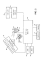
外科手技を行うためにロボットシステムを制御するシステム及び方法が開示される。図1には、患者に対して外科手技を行うためのロボットシステム10を示している。
Systems and methods for controlling a robotic system to perform a surgical procedure are disclosed. FIG. 1 shows a
外科手技の前に、医療従事者は患者の術前データを収集することができる。術前データは、x線、CTスキャン、MRI、又は術前データを収集することのできる任意の他のモダリティ(modality)によるものとすることができる。収集された術前データは、ロボットシステム10によって使用するためにセーブし、記憶することができる。
Prior to the surgical procedure, medical personnel can collect patient preoperative data. Pre-operative data can be by x-ray, CT scan, MRI, or any other modality that can collect pre-operative data. The collected preoperative data can be saved and stored for use by the
一実施形態では、患者は外科手技の際に支持ステーション12上に置かれる。支持ステーション12は、患者の解剖学的構造(anatomy)を固定する支持体すなわち外科用ホルダ14を有している。患者の解剖学的構造を、図1の符号Aにより示している。解剖学的構造は、実施形態によっては、大腿骨F及び/又は脛骨Tとすることができる。外科用ホルダ14は任意の方法で支持ステーション12につなぐことができることを理解されたい。
In one embodiment, the patient is placed on the
図1において、支持ステーション12は、トラック18を有する手術台16を備えている。外科用ホルダ14は、外科用ホルダ14が手術台16上でトラック18に沿って移動できるように、トラック18に接続されている。外科手技中に、医療従事者は、外科用ホルダ14をトラック18に沿って前後にスライドさせて、解剖学的構造を位置決めすることができる。外科用ホルダ14は、該外科用ホルダ14が定位置にあるものとなるように、トラック18に固定することができる。例えば、外科用ホルダ14は、解剖学的構造が最適な位置にあるときに、定位置に固定することができる。適切な外科用ホルダ14の一実施形態が、「Multi-Position Limb Holder」と題する2012年7月20日出願の米国特許出願第13/554,010号に示されている。この米国特許出願の内容は、引用することによりその全体が本明細書の一部をなすものとする。
In FIG. 1, the
外科用ホルダ14は定位置にあるものとすることができるが、解剖学的構造は、外科用ホルダ14に対して依然として動くことができるように外科用ホルダ14内に置かれる。例えば、解剖学的構造は、最大で6自由度を含む、1以上の自由度において外科用ホルダ14に対して動くことができる。それにより、解剖学的構造は、実質的には、ロボットシステム10における動的な部分である。さらに、外科用ホルダ14は、解剖学的構造に力を加えるときに、該解剖学的構造の全体的な、又は大きな動きが制限されるように、該解剖学的構造をしっかりと保持するものであり、その結果、ロボットシステム10が該解剖学的構造を処置できる。
Although the
ロボットシステム10は、手術器具22を操作して解剖学的構造を処置するために用いることができるマニピュレータ20を有している。マニピュレータ20の一実施形態は、「Surgical Manipulator Capable of Controlling a Surgical Instrument in Multiple Modes」と題する2013年3月15日出願の米国仮特許出願第61/792,251号に記載されている。この米国仮特許出願の内容は、引用することによりその全体が本明細書の一部をなすものとする。
The
マニピュレータ20は、カート24と、カート24から遠位端(distal end)まで延びている一対のアーム26とを有している。器具22は、一対のアーム26の遠位端に結合される。器具22は、任意のやり方でマニピュレータ20と一体化される場合があることを理解されたい。一実施形態では、器具22は、該器具22から延びるエネルギーアプリケータ(energy applicator)34を有している。エネルギーアプリケータ34は、超音波チップ、バー(bur)又は外科手技を行うための任意の他の処置デバイスとすることができる。外科用ホルダ14は通常、マニピュレータ20に対して固定される。
The
マニピュレータ20及び器具22は、位置、力・トルク等を検知するための1以上のセンサ及び/又はエンコーダも有することができる。センサ及びエンコーダは、マニピュレータ20及び器具22に関連する物理データ又は他のタイプのデータを提供するために本技術分野において知られている任意の形式のものとすることができる。1つのタイプのセンサは力・トルクセンサ28であり、器具22に加えられた力及びトルクを検出することができる。適切な力・トルクセンサ28の一実施形態が、「Force/Torque Transducer」と題する2013年3月12日出願の米国仮特許出願第61/777,596号に示されている。この米国仮特許出願の内容は、引用することによりその全体が本明細書の一部をなすものとする。
The
また、マニピュレータ20は、マニピュレータコントローラ30も有している。マニピュレータコントローラ30は、力・トルクセンサ28を含む、センサ及びエンコーダと通信する。マニピュレータコントローラ30は、力・トルクセンサ28により検知された力及びトルクがマニピュレータコントローラ30に返されるように、力・トルクセンサ28と通信することができる。マニピュレータコントローラ30は更に、ナビゲーションシステム32と通信する。
The
ロボットシステム10、より詳細には、マニピュレータ20は、手動で、又は自律的に動作することができる。手動で動作するとき、ロボットシステム10は、手動モードにおいて動作している。手動モードでは、医療従事者が、ロボットシステム10にコマンドを適用することによって、器具22を手動で位置決めすることができる。コマンドを適用する一例は、医療従事者が器具22を握り、器具22に力・トルクを加えることを含む。医療従事者によって適用されたコマンドに基づいて、ロボットシステム10は、アーム26を作動させて、それに応じて、器具22が実質的に同時にリアルタイムに所望の位置に移動する。
The
ロボットシステム10は、器具22を自律制御するように構成されている。より詳細には、ロボットシステム10は、自律動作モード又は半自律動作モードにおいて器具22を自律制御する。自律モード又は半自律モードでは、マニピュレータコントローラ30は、プリロードされたデータ、ナビゲーションシステム32からのデータ、及びエンコーダからのデータを処理して、器具22が従うことになる経路を導き出す。経路はプリプログラミングするか、又はあらかじめ決定することができる。ロボットシステム10はアーム26を作動させ、その経路に沿って器具22を自律的に移動させて、解剖学的構造に処置を施す。ロボットシステム10は、医療従事者からの入力を実質的に用いることなく、手技を行う。
The
半自律モードでは、ロボットシステム10は、その経路に沿って器具22を自律的に移動させる。しかし、医療従事者が、コマンドをアサートして、ロボットシステム10の動作を制御することができる。例えば、ロボットシステム10は、器具を移動できるようにするために、医療従事者がロボットシステム10に関連付けられた制御ボタン又はスイッチを持続的に押下することを要求する場合がある。医療従事者がボタン又はスイッチを放すと、器具22の動きが一時的に停止する。自律モード又は半自律モードにおいて利用される1つの適切なナビゲーションシステムが、「Navigation System Including Optical and Non-Optical Sensors」と題する2012年9月26日出願の米国仮特許出願第61/705,804号に記載されている。この米国仮特許出願の内容は、引用することによりその全体が本明細書の一部をなすものとする。しかし、他のナビゲーションシステムも使用できることを理解されたい。
In the semi-autonomous mode, the
ナビゲーションシステム32は、ナビゲーションコンピュータ38を収容したコンピュータカートアセンブリ36を有するものとすることができる。ナビゲーションインターフェースは、ナビゲーションコンピュータ38と動作可能に通信する。ナビゲーションインターフェースによって、医療従事者は、ロボットシステム10と通信できるようになる。ナビゲーションインターフェースは、医療従事者がナビゲーションコンピュータ38と通信できるようにするために、少なくとも1つのディスプレイ40、42と、キーボード及びマウス等の入力デバイス44、46とを含む。
The
ナビゲーションコンピュータ38は、マニピュレータ20を制御するために、マニピュレータコントローラ30と協働する。ナビゲーションコンピュータ38は、マニピュレータコントローラ30がマニピュレータ20の動きを、それゆえ、器具22の動きを指示できるように、マニピュレータコントローラ30に器具22の姿勢データを与える。
The
ローカライザ48は、ナビゲーションコンピュータ38と通信する。図1に示している実施形態において、ローカライザ48は光学ローカライザ48であり、カメラユニット50を有している。カメラユニット50は、1以上の光センサ52を収容する外部ケーシングを有している。幾つかの実施形態では、少なくとも2つの光センサ52が利用される。他の実施形態では、3つ以上の光センサ52が用いられる場合がある。
ナビゲーションシステム32は1以上のトラッカを含む。トラッカは、ポインタトラッカPT、器具トラッカ54、第1の患者トラッカ58及び第2の患者トラッカ60を含むことができる。トラッカはアクティブ型マーカ56を含む。アクティブ型マーカ56は、発光ダイオードすなわちLEDとすることができる。他の実施形態では、トラッカ54、58、60は、カメラユニット50から放射された光を反射する反射体等の、パッシブ型マーカを有することができる。ロボットシステム10の一部とすることができる更なる構成要素を追跡するために、ナビゲーションシステム32に更なるトラッカを組み込むことができることを理解されたい。
The
図1に示している実施形態では、第1の患者トラッカ58は患者Pの大腿骨Fにしっかり固定され、第2の患者トラッカ60は患者Pの脛骨Tにしっかり固定される。患者トラッカ58、60は、骨の複数の部分にしっかり固定される。さらに、器具トラッカ54は器具22にしっかり固定される。トラッカ54、58及び60は、役に立つと思われる任意のやり方で個々の構成要素に固定することができる。
In the embodiment shown in FIG. 1, the
図2に示すように、各LEDは、関連するトラッカのハウジング(図示せず)内に位置し、ナビゲーションコンピュータ38との間でデータを送受信するトラッカコントローラ62に接続される。また、トラッカ54、58、60は、トラッカ54、58、60の角速度を測定する3次元ジャイロスコープセンサ64も含む。また、トラッカ54、58、60は、x、y、z座標系において加速度を測定する加速度計66も含む。
As shown in FIG. 2, each LED is located in an associated tracker housing (not shown) and is connected to a tracker controller 62 that sends and receives data to and from the
トラッカ54、58、60のアクティブ型マーカ56から姿勢データを伝えるために、カメラユニット50は、光センサ52と通信するカメラコントローラ68を有している。その際、カメラコントローラ68は、ナビゲーションコンピュータ38に姿勢データを伝える。その際、ナビゲーションコンピュータ38は、更なる術前データとともに姿勢データを処理して、患者の解剖学的構造との関連において器具22、それゆえ、エネルギーアプリケータ34の姿勢を伝える。一実施形態では、ナビゲーションインターフェースは、そのようなデータを医療従事者に伝える。医療従事者がロボットシステム10とやりとりするために、当業者がこれまでの実施形態において説明されていない他の方法を見つけることができることを理解されたい。
In order to transmit attitude data from the
外科手技中に、ロボットシステム10は、手動モードから半自律モード又は自律モードに切り替わることが望ましい。骨切断手技等の幾つかの手技では、器具22が骨と関わっているときに解剖学的構造が器具22と同じ速度で動かないように、解剖学的構造が外科用ホルダ14内でしっかり配置されることが望ましい。さもなければ、器具22は骨を切断することができない。言い換えると、外科用ホルダ14内に固定されるときに、解剖学的構造は、何らかの最小の剛性又は他の特性を有することが望ましい。さらに、外科手技中に器具22が解剖学的構造に当てられるときに、解剖学的構造が器具22より遅い速度で動くのを確実にするために、剛性等の幾つかの特性の値に基づいてロボットシステム10を制御することが望ましい。
During a surgical procedure, the
器具22が解剖学的構造に当てられるときの解剖学的構造の動きを考慮するために、ロボットシステム10は、解剖学的構造の1以上の特性に基づいて較正される。1以上の特性は、剛性特性(k)、減衰(damping)特性(b)、質量(m)、減衰比(ζ)、周波数応答(ωn)及び/又は他の特性とすることができる。剛性特性(k)は、ばね定数として更に定めることができる。別の例では、特性は、解剖学的構造が外科用ホルダ14によって固定される範囲を表すデータを含む。より詳細には、特性は、外科用ホルダ14に対して解剖学的構造が動く範囲を表すデータを含む。
In order to account for the movement of the anatomy when the
図3は、外科手技中に患者Pの解剖学的構造を操作するためにロボットシステム10を制御する基本ステップを示している。ステップ72において、解剖学的構造に力を加えて解剖学的構造による反応を生成する。ステップ74において、解剖学的構造の反応が測定される。ステップ76において、その反応に基づいて解剖学的構造の特性が計算される。ステップ78において、計算された特性に基づいて、解剖学的構造に対して器具22が自律制御される。
FIG. 3 shows the basic steps of controlling the
ステップ72において、解剖学的構造に力を加えるために、一般的に、解剖学的構造に隣接するように、又は当たるように加力(force-applying)デバイスが位置決めされる。一実施形態では、ロボットシステム10、より詳細にはマニピュレータコントローラ30は、力を加えるために、加力デバイスを解剖学的構造に向かって能動的に動かす。あるいは、ロボットシステム10は静止していることができ、力を加えるために、加力デバイスがロボットシステム10から解剖学的構造に向かって伸長する。加力デバイスのそのような動きは、マニピュレータコントローラ30から独立して行うことができる。加力デバイスは任意の適切な構成を有することができる。例えば、解剖学的構造を操作する器具22が加力デバイスである。別の例では、センサ又はゲージ(gauge)等の、器具22以外のデバイスが、加力デバイスとしての役割を果たし、解剖学的構造に当たるように位置決めされる。器具22以外の任意の適切なデバイスが、加力デバイスとしての役割を果たすことができる。
In
医療従事者は、ロボットシステム10、より詳細にはマニピュレータコントローラ30が、器具22又は他の加力デバイスを解剖学的構造に当たるように位置決めできるように、手動モードにおいて入力を与えることができる。場合によっては、エネルギーアプリケータ34が解剖学的構造に当たるように位置決めされる場合がある。また、場合によっては、解剖学的構造に当接して位置決めするために、手術器具22には、その遠位端において非侵襲性で生体適合性のある構造を有する較正プローブ(図示せず)が設けられる。
Medical personnel can provide input in a manual mode so that the
代替的なバージョンでは、ロボットシステム10は、ステップ72において力を加える前に、器具22を解剖学的構造に当接して自律的に位置決めするために、半自律又は自律モードにおいて利用される場合がある。医療従事者は、自律動作中に介入し、解剖学的構造に当接する器具22の位置決めを指示するために、ナビゲーションインターフェースとやりとりすることができる。医療従事者は、当業者が器具22の位置を指示するのに役に立つと判断する任意のやり方において、マニピュレータ20、ナビゲーションシステム32又はロボットシステム10の任意の他の構成要素とやりとりできることを理解されたい。さらに、医療従事者は、器具22を解剖学的構造に当接して位置決めするときに、手動モード、自律モード及び/又は半自律モード間で切り替えることができる。
In an alternative version, the
ステップ72において、解剖学的構造に力が加えられる。ステップ72の一実施形態では、器具22が解剖学的構造に力を加える。別の実施形態では、器具22以外の加力デバイスが、解剖学的構造に力を加える。いずれの場合でも、手動モード、自律モード及び/又は半自律モードにおいて、解剖学的構造に力を加えることができる。一実施形態では、力はあらかじめ決定される。さらに、力は1自由度において加えることができる。あるいは、力及びトルクは、6自由度等の幾つかの自由度において加えられる場合がある。
In
一実施形態では、力はステップ関数(step function)に従って解剖学的構造に加えられる。その場合、力は第1の間隔において第1のレベルで加えられ、第1の間隔に続く第2の間隔において第2のレベルで加えられる。第1のレベルは第2のレベルより高いものとすることができるか、又はその逆の場合もある。したがって、ロボットシステム10は、解剖学的構造に種々のレベルの力を加えることができる。ステップ関数は、任意の適切な数のレベル及び間隔を含むことができる。
In one embodiment, the force is applied to the anatomy according to a step function. In that case, the force is applied at a first level in a first interval and at a second level in a second interval following the first interval. The first level can be higher than the second level, or vice versa. Thus, the
別の実施形態では、力は、インパルス関数F(t)に従って解剖学的構造に加えられる。この実施形態では、力が解剖学的構造に加えられ、解剖学的構造の反応を時間に応じて測定した信号が記録される。 In another embodiment, the force is applied to the anatomy according to an impulse function F (t). In this embodiment, force is applied to the anatomical structure and a signal measuring the response of the anatomical structure as a function of time is recorded.
更に別の実施形態では、ステップ72は較正処理を起動(activate)することを含む。したがって、解剖学的構造に力を加えることは、較正処理の起動に応じて行われる。較正処理は、マニピュレータコントローラ30内に記憶された較正プログラムとすることができる。記憶される較正プログラムは、コンピュータプログラムを記憶することができ、ロボットシステム10の一部である任意の媒体に記憶することができる。ナビゲーションインターフェースは、較正処理を開始するようにユーザに促すことができる。あるいは、較正処理を自動的に開始することができる。
In yet another embodiment,
較正処理において、記憶された較正プログラムは、マニピュレータコントローラ30と協働して、解剖学的構造に力を加えるように器具22に指示することができる。一実施形態では、器具22が較正処理全体を通して解剖学的構造との接触を維持するものとなるように、解剖学的構造に力が加えられる。それに加えて、又はその代わりに、マニピュレータ20は、所定のしきい値の力に達するまで、解剖学的構造に加えられる力を増やし続けることができる。
In the calibration process, the stored calibration program can instruct
解剖学的構造は、力が加えられた後に反応を生成する。後に詳細に説明されるように、解剖学的構造の生成された反応は、種々の形の任意の組み合わせをとることができる。一実施形態では、解剖学的構造の生成された反応は、機械的な反応とすることができる。例えば、生成された反応は、解剖学的構造の機械的な動き、より詳細には、解剖学的構造の変位又は回転運動とすることができる。解剖学的構造の生成された反応が機械的ではない形をとる場合もあることが、当業者には理解されよう。例えば、生成された反応は、電気的な反応とすることができる。 The anatomical structure produces a reaction after a force is applied. As described in detail later, the generated response of the anatomical structure can take any combination of various forms. In one embodiment, the generated response of the anatomical structure can be a mechanical response. For example, the response generated can be a mechanical movement of the anatomical structure, more specifically a displacement or rotational movement of the anatomical structure. One skilled in the art will appreciate that the generated response of the anatomical structure may take a non-mechanical form. For example, the generated reaction can be an electrical reaction.
解剖学的構造による反応が生成された後に、ステップ74において、その反応が測定される。この反応は、種々の方法に従って測定することができる。反応測定デバイスが反応を測定する。ステップ74の一実施形態では、反応は、力・トルクセンサ28を用いて測定される。力・トルクセンサ28を器具22に関連付けることができる。器具22が解剖学的構造に力及び/又はトルクを加えたときに、力・トルクセンサ28は力及び/又はトルクを測定することができる。あるいは、力・トルク28は、器具22以外のデバイスに関連付けることができる。力及び/又はトルクは、時間に応じて測定することができる。さらに、力及び/又はトルクは、離散的又は連続的に測定することができる。
After the anatomical response is generated, at
ステップ74の別の実施形態では、解剖学的構造の反応は、関節トルク(joint torque)を測定することによって測定される。関節トルクは、マニピュレータ20の関節のうちの1つに関連するトルクに対応する。任意の適切なセンサ及び/又はエンコーダが、関節トルクを検知することができる。さらに、2つ以上の関節トルクを測定することができる。一実施形態では、関節トルクは、以下の式(1)を用いて、計算され、ツール中心点(tool center point, TCP)の力・トルクに変換される。式(1)において、(J’)はTCPから関節までのヤコビアンの転置であり、(t)は関節トルクのベクトルである。関節トルクは、以下の式(2)に示すように、器具22を操作するために用いられるモータコントローラによって引き込まれる電流から計算することができる。ただし、(kt)はモータトルク定数であり、(i)は電流である。さらに、関節トルクセンサを用いて、関節トルクの推定値を求めることができる。関節トルクは、種々の他の方法に従って測定することができる。

ステップ74の更に別の実施形態では、解剖学的構造の反応は、解剖学的構造の変位を測定することによって測定される。変位は、力を加えられたことによって解剖学的構造が動く距離とすることができる。変位は、時間に応じて測定することができる。さらに、変位は離散的又は連続的に測定することができる。幾つかの実施形態では、所望の変位に達するまで、マニピュレータ20は、器具22を解剖学的構造に当て続けることができる。任意の適切なデバイス又は方法を利用して、解剖学的構造の変位を測定することができる。一例では、ナビゲーションシステム32が、トラッカ58及び60の位置の変化を測定することによって変位を計算する。例えば、ナビゲーションシステム32は、ステップ72において力を加える前に、解剖学的構造の初期位置を求めることができる。力が加えられた後に、ナビゲーションシステム32は、解剖学的構造の変位位置を求めることができる。ナビゲーションシステム32はその後、変位位置を初期位置と比較し、変位を求めることができる。
In yet another embodiment of
ロボットシステム10は、変位を測定するとき、最終的な力及び変位測定値を記録することができる。ロボットシステム10が最終的な力及び変位測定値を記録する前に解剖学的構造及び器具22が平衡点(equilibrium point)に達するものとなるように、ステップ74において、マニピュレータ20は、定められた整定時間(settling time)だけ待つことができる。さらに、マニピュレータコントローラ30は、エンコーダ及び運動学的計算により、解剖学的構造の変位を計算することができる。解剖学的構造の変位を計算する代替的な方法を当業者が見つけることができることを理解されたい。
When the
解剖学的構造の反応を測定する際に、解剖学的構造の質量(m)を考慮することができる。一実施形態では、解剖学的構造の質量は術前データから推定される。さらに、解剖学的構造の質量は、外科用ホルダ14の質量に加えることができる。したがって、解剖学的構造の反応を測定する際に、解剖学的構造及びホルダ14の質量を考慮することができる。さらに、反応を測定するときに、質量及び変位の両方を考慮に入れることができる。
In measuring the response of the anatomical structure, the mass (m) of the anatomical structure can be taken into account. In one embodiment, the mass of the anatomy is estimated from preoperative data. Further, the mass of the anatomical structure can be added to the mass of the
解剖学的構造の反応は、上記の実施形態の任意の組み合わせに従って測定することができる。一実施形態では、その方法の幾つかのステップが異なる時刻に行われる。例えば、ステップ72及び74が異なる時刻に行われる。より詳細には、解剖学的構造の反応が測定される前に、解剖学的構造に力が加えられる。別の例では、ステップ72及び78が異なる時刻に行われる。詳細には、器具22の自律制御前に、解剖学的構造に力が加えられる。そのような場合には、解剖学的構造に力を加えるステップ72は、器具22を自律制御するステップ78から独立して別に行われる。
The anatomical response can be measured according to any combination of the above embodiments. In one embodiment, several steps of the method are performed at different times. For example, steps 72 and 74 are performed at different times. More particularly, force is applied to the anatomy before the response of the anatomy is measured. In another example, steps 72 and 78 are performed at different times. In particular, force is applied to the anatomy prior to autonomous control of the
あるいは、本方法の幾つかのステップを、同時に行うことができる。例えば、力が加えられるのと同時に解剖学的構造の反応が測定されるように、ステップ72及び74を同時に行うことができる。別の例では、ステップ72がステップ78と同時に行われる。詳細には、器具22が自律制御されるのに応じて、力が加えられる。そのような場合には、器具22を自律制御する前に、力を加えるステップ72が行われる必要はない。すなわち、器具22の自律制御は、解剖学的構造にあらかじめ力を加えることなく開始することができる。むしろ、器具22の自律制御中に、解剖学的構造に力が絶えず加えられる。さらに、ステップ74及び76をステップ78と同時に行うことができる。すなわち、器具22が自律制御されるのに応じて、解剖学的構造の反応を測定することができ、解剖学的構造の特性を計算することができる。
Alternatively, several steps of the method can be performed simultaneously. For example, steps 72 and 74 can be performed simultaneously so that the response of the anatomy is measured at the same time as the force is applied. In another example, step 72 occurs concurrently with
さらに、本方法の最も広い範囲から逸脱することなく、解剖学的構造の反応を測定する代替的な方法を当業者が見つけることができることを理解されたい。 Furthermore, it should be understood that one skilled in the art can find alternative ways of measuring anatomical responses without departing from the broadest scope of the method.
上記のように、ステップ76において、解剖学的構造の測定された反応に基づいて、解剖学的構造の特性が計算される。種々の実施形態に従って特性を計算することができる。一実施形態では、特性は静的手法を用いて測定される。この手法では、解剖学的構造の剛性特性(k)が特定される。解剖学的構造に加えられる力は既知であり、(F)によって表される。解剖学的構造の計算された変位も既知であり、(x)によって表される。マニピュレータコントローラ30は、ステップ76において剛性特性(k)について解くために、力(F)及び変位(x)を以下の式(3)に入力することによって、力(F)及び計算された変位(x)を処理する。
![]()
![]()
式(3)において、解剖学的構造の静的な撓み(deflection)が測定される。剛性特性(k)はばね定数であり、定常状態条件下で推定することができる。解剖学的構造の特性を計算するための代替の静的手法を当業者が見つけることができることを理解されたい。 In equation (3), the static deflection of the anatomical structure is measured. The stiffness characteristic (k) is a spring constant and can be estimated under steady state conditions. It should be understood that those skilled in the art can find alternative static techniques for calculating anatomical characteristics.
別の実施形態では、動的手法を用いて、特性が測定される。この手法では、解剖学的構造のステップ応答又はインパルス応答が測定される。質量・ばね・ダンパのモデルに関する以下の特性方程式(4)を用いて、パラメータが推定される。
式(4)において、(m)はホルダ及び/又は解剖学的構造の質量であり、(b)は減衰(damping)係数等の減衰特性であり、(k)はばね定数であり、(x’’)は、変位の時間に対する二次導関数(例えば、加速度)であり、(x’)は変位の時間に対する一次導関数(例えば、速度)であり、(x)は変位である。式(4)において、パラメータ(m、b又はk)のうちの少なくとも1つを仮定するか、又は既知のものとして、その他のパラメータを容易に推定することができる。例えば、3つのパラメータのうちの2つが既知である場合には、これにより、第3のパラメータの推定を向上させることができる。一例では、質量が既知であるか、又は入手可能な臨床データから推定することができる。別の例では、ばね定数(k)が静的試験により計算及び推定される。いずれの例でも、実験データから残りの2つの変数を計算することができる。あるいは、両方の例の手法を組み合わせて、(m)及び(k)の両方に関する初期推定値を与えて、減衰特性(b)を実験データから計算することができる。 In equation (4), (m) is the mass of the holder and / or anatomical structure, (b) is a damping characteristic such as a damping coefficient, (k) is a spring constant, (x '') Is the second derivative (eg, acceleration) with respect to time of displacement, (x ′) is the first derivative (eg, velocity) with respect to time of displacement, and (x) is the displacement. In equation (4), at least one of the parameters (m, b or k) can be assumed or other parameters can be easily estimated as known. For example, if two of the three parameters are known, this can improve the estimation of the third parameter. In one example, the mass is known or can be estimated from available clinical data. In another example, the spring constant (k) is calculated and estimated by static testing. In either example, the remaining two variables can be calculated from the experimental data. Alternatively, both example approaches can be combined to provide an initial estimate for both (m) and (k), and attenuation characteristics (b) can be calculated from experimental data.
ステップ76の別の実施形態では、特性の計算は、マニピュレータコントローラ30によって作成された経時的な変位のグラフから、解剖学的構造の反応の共振周波数(ωn)及び減衰比(ζ)を推定することを含む。推定された質量を用いて、以下の式(5)及び式(6)を解くことで、剛性特性(k)及び減衰特性(b)を計算することができる。他の例では、質量、剛性特性(k)及び減衰特性(b)が推定される。
更に別の実施形態では、ステップ76は、変位と時間との関係のデータから評価されるような、計算された反応xc(t)と実験的な反応x(t)との平均二乗誤差を最小にするパラメータ値を探索する反復型最適化ルーチンの実行を含む。この実施形態では、式(7)において質量、ばね、ダンパモデルHsに関する完全な伝達関数を利用して、質量(m)、減衰特性(b)及び剛性特性(k)の値を計算する。
式(8)において、力の入力すなわちf(t)は既知であり、f(t)のラプラス変換が計算されて、F(s)が求められる。したがって、式(7)におけるF(s)は、力の入力のラプラス変換である。式(7)において、X(s)は並進出力(translation output)のラプラス変換であり、sはラプラス周波数変数である。式(7)において、X(s)は、F(s)の計算値と、(m)、(k)及び(b)の推定値とを用いて求められる。X(s)がわかると、以下の式(9)によって示されるような、逆ラプラス変換を用いて、X(s)を周波数領域からxc(t)である時間領域に変換する。その後、xc(t)とx(t)との平均二乗誤差が計算される。その後、本処理は、平均二乗誤差が許容可能な差以内に収束するまで、(m)、(k)及び(b)に関する更新された推定値を用いて繰り返される。
解剖学的構造の特性を計算するために上記で言及されていない代替の数学的方法を用いることを当業者が予想できることは理解されたい。 It should be understood that one skilled in the art can expect to use alternative mathematical methods not mentioned above to calculate anatomical characteristics.
上記のように、ステップ78において、ロボットシステム10は、計算された特性に基づいて、解剖学的構造に対して器具22を自律制御する。それにより、本方法は、器具22を自律制御するときに、解剖学的構造の特性を考慮する。マニピュレータコントローラ30は、計算された特性に基づいて、解剖学的構造に対する器具22、それゆえ、エネルギーアプリケータ34の先端部の位置を制御することができる。一実施形態によれば、器具22の自律制御は、計算された特性を利用して外科手技中の解剖学的構造の動きを考慮することを含む。
As described above, in
別の実施形態では、計算された特性は、自律モード又は半自律モードにおいてマニピュレータの送り速度(feed rate)を制御する際に1つの要素として使用される。マニピュレータの送り速度は、「Surgical Manipulator Capable of Controlling a Surgical Instrument in Multiple Modes」と題する2013年3月15日出願の米国仮特許出願第61/716,251号に記載されている。この米国仮特許出願の内容は、引用することによりその全体が本明細書の一部をなすものとする。 In another embodiment, the calculated characteristics are used as an element in controlling the manipulator feed rate in autonomous or semi-autonomous mode. The manipulator feed rate is described in US Provisional Patent Application No. 61 / 716,251, filed Mar. 15, 2013 entitled “Surgical Manipulator Capable of Controlling a Surgical Instrument in Multiple Modes”. The contents of this US provisional patent application are hereby incorporated by reference in their entirety.
一例では、器具22の送り速度は、計算された特性に基づいて調整される。例えば、送り速度は、外科手技中に器具22が解剖学的構造に当てられたときに解剖学的構造が動く速度より速いものとなるように調整される。このようにして、器具22の送り速度が、外科用ホルダ14内で動く場合がある解剖学的構造と器具22が接触できるようにするのに十分であることを確実にするために、計算された特性が考慮される。
In one example, the feed rate of the
別の例では、送り速度は、解剖学的構造が外科用ホルダ14によって固定される範囲を表すデータに基づいて調整される。より詳細には、送り速度は、解剖学的構造が外科用ホルダ14に対して動く範囲を表すデータに基づいて調整される。そのようなデータは、器具22の実際の位置を、解剖学的構造に対する器具22の意図した位置と比較することによって導き出すことができる。ナビゲーションシステム32は、解剖学的構造及び器具22を追跡して、実際の位置を求める。実際の位置は、器具22の横断切断経路(traversed cut path)を含むことができる。意図した位置は、意図した横断切断経路を表す所定のプリロードされたデータとすることができる。器具22の切断経路は、複数の離散点において求めることができる。実際の経路と意図した経路とのプロファイル誤差を求めることができる。その後、プロファイル誤差を所定のしきい値と比較することができる。一例では、しきい値を超えるプロファイル誤差を有する横断切断経路点のパーセンテージが容認できないと見なされた場合は、送り速度が減速され、及び/又は通知が表示される。場合によっては、プロファイル誤差目標値及び容認可能なパーセンテージは、調整することができるか、又は可変とすることができる。そのような調整は、例えば、その切断が荒切り(rough cut)か、仕上げ切り(finish cut)かに応じて行うことができる。さらに、そのような調整は、切断対象の解剖学的構造の重症度に基づいて行うことができる。アンダーカット(undercut)は、オーバーカット(overcut)とは異なるしきい値を有することもできる。別の例では、上記の方法を利用して、器具22による実際の骨除去と、機器22による意図した骨除去とを比較する。
In another example, the feed rate is adjusted based on data representing the extent to which the anatomy is secured by the
別の実施形態では、器具の自動制御は、解剖学的構造の計算された特性に基づいて、器具22の最大送り速度を設定することを含む。場合によっては、ロボットシステム10は、外科手技を受ける詳細な解剖学的構造に応じて、器具22のデフォルト最大送り速度を指定することができる。言い換えると、デフォルト最大送り速度は、対象となる解剖学的構造に応じて異なる場合がある。その一方で、計算された特性に応じて、ロボットシステム10は、デフォルト最大送り速度以下となるように最大送り速度を設定することができる。例えば、計算された特性が、比較的硬い解剖学的構造を示す場合には、ロボットシステム10は、最大送り速度をデフォルト最大送り速度に設定することができる。解剖学的構造が比較的硬い場合、器具22を当てる際に不正確になる可能性は低いので、ロボットシステム10は最大送り速度を維持することができる。あるいは、例えば、計算された特性が、比較的緩く固定された解剖学的構造を示す場合には、ロボットシステム10は、器具22の最大送り速度を、デフォルト最大送り速度未満に、すなわちデフォルト最大送り速度未満である送り速度範囲内に設定することができる。ロボットシステム10は、解剖学的構造が緩く固定されることから生じる場合のある、器具22を当てる際の不正確さを解消するために、最大送り速度を制限することができる。他の実施形態では、最大送り速度は、上記のようなデフォルト最大送り速度にかかわらず、単に、計算された特性に応じて設定される。
In another embodiment, automatic control of the instrument includes setting the maximum feed rate of the
さらに、計算された特性に基づく器具22の自律制御は、計算された特性をシミュレーションプログラムにおいて適用することを含むことができる。シミュレーションプログラムは、外科手技中に解剖学的構造に対する器具22の動きを、より詳細には、エネルギーアプリケータ34の動きをモデル化することができる。一実施形態では、シミュレーションは、骨切削手技をモデル化する。
Further, autonomous control of the
本方法の範囲から逸脱することなく、上記の実施形態において説明される特性以外の計算された特性に基づく、器具22を自律制御するための使用法を当業者が見つけることができることは理解されたい。
It should be understood that one skilled in the art can find uses for autonomously controlling the
計算された特性に基づいて、ロボットシステム10は、図4及び図5に示すように、メッセージ又は通知80を与えることができる。通知80は、外科手技中に医療従事者を助けるものである。通知80は、ユーザインターフェース等の任意の適切な媒体上で与えることができる。図4及び図5において、通知80はナビゲーションシステム32のディスプレイ42上に与えられる。通知80は、画像、テキスト、又は画像及びテキストの組み合わせによって与えることができる。さらに、通知80は動画とすることができる。
Based on the calculated characteristics, the
通知80は、計算された特性に基づいて与えられる。一実施形態では、通知80は、計算された特性の評価に基づいて与えられる。例えば、通知80は、計算された特性と、最適な動作に関連するしきい値との比較に基づいて与えることができる。しきい値は、最小しきい値又は最大しきい値とすることができる。計算された特性が最大しきい値より大きいか、又は最小しきい値より小さい場合には、ロボットシステム10は通知80を与える。例えば、剛性k(又はパラメータm、b及びkの組み合わせ)に関する最小しきい値が決定される場合がある。計算された剛性が剛性kに関する最小しきい値より小さい場合には、ロボットシステム10は、医療従事者に、解剖学的構造がよりしっかり固定されるまで手技が継続できないという通知80を与える。
Notification 80 is provided based on the calculated characteristics. In one embodiment, the notification 80 is provided based on a calculated property evaluation. For example, the notification 80 can be provided based on a comparison of the calculated characteristics with a threshold associated with optimal operation. The threshold can be a minimum threshold or a maximum threshold. If the calculated characteristic is greater than the maximum threshold or less than the minimum threshold, the
その代わりに、又はそれに加えて、計算された特性に基づいて、自律モード又は半自律モードにおける送り速度を、機械加工精度を維持するために必要なレベルに調整することができる。一例では、送り速度は、解剖学的構造がよりしっかり固定されるまで、又は解剖学的構造がよりしっかり固定されない限り減速される。詳細には、解剖学的構造が、低い剛性を示す自由度においてよりしっかり固定されるまで、又はよりしっかり固定されない限り、送り速度を減速することができる。送り速度の調整は、医療従事者が送り速度を手動で調整する必要がないように、自動的及び受動的なものとすることができる。むしろ、より迅速な機械加工が望ましい場合には、解剖学的構造の剛性が調整される。その後、ロボットシステム10は、解剖学的構造がよりしっかり固定された場合には、医療従事者に対して、送り速度を上げることができるという通知80を表示することができる。
Alternatively or additionally, based on the calculated characteristics, the feed rate in autonomous or semi-autonomous mode can be adjusted to the level required to maintain machining accuracy. In one example, the feed rate is reduced until the anatomy is more firmly fixed or unless the anatomy is more firmly fixed. In particular, the feed rate can be reduced until the anatomical structure is more firmly fixed in a degree of freedom exhibiting low stiffness, or unless it is more firmly fixed. Adjustment of the feed rate can be automatic and passive so that medical personnel do not need to manually adjust the feed rate. Rather, if faster machining is desired, the stiffness of the anatomy is adjusted. Thereafter, the
他の実施形態では、計算された特性が、最適動作に関する所定の特性範囲と比較される。計算された特性がその範囲外の場合には、ロボットシステム10は、通知80を送ることができる。例えば、ロボットシステム10が、剛性特性(k)等の計算された特性が最適動作に関する範囲外にあると判断した場合は、ロボットシステム10は、通知80を送り、計算された特性が範囲外にあること、又は外科手技が中止されるべきであることを医療従事者に警告することができる。他方、剛性特性(k)が最適動作特性の範囲内にある場合には、ロボットシステム10は、外科手技が継続できることを医療従事者に通知することができる。さらに、上記の実施形態は、較正処理において行うことができる。例えば、較正処理は、計算された特性が最適動作特性の範囲内にあるときに終了することができる。
In other embodiments, the calculated characteristic is compared to a predetermined characteristic range for optimal operation. If the calculated characteristic is outside the range, the
多くの場合に、計算された特性に基づいて患者の解剖学的構造を調整する方法に関する指示を伴う通知80を与えることが有利である。通知80は、解剖学的構造がよりしっかり固定されるように、外科用ホルダ14内で解剖学的構造を位置決めし直すように医療従事者に警告することができる。解剖学的構造を位置決めし直すことは、外科用ホルダ14を操作することによって行われる。したがって、通知80は、外科用ホルダ14を操作する(例えば、動かす、調整する)方法に関する指示を示唆することができる。解剖学的構造の位置は、外科用ホルダ14を用いて、複数の自由度に沿って調整可能に設定することができる。解剖学的構造に加えられる力は、各自由度に対する解剖学的構造による反応を生む。自由度ごとに、解剖学的構造の反応が測定される。計算された特性は、自由度ごとに求められる。計算された特性に基づいて、自由度のうちのいずれかに対して解剖学的構造が調整されるべきであるか否かに関する判断を行うことができる。その判断は、計算された特性が所定のしきい値又は範囲を超えたか否かを含む、種々の方法に従って行うことができる。調整の大きさ又は範囲も判断することができる。
In many cases, it is advantageous to provide a notification 80 with instructions on how to adjust the patient's anatomy based on the calculated characteristics. The notification 80 can alert the health care professional to reposition the anatomy within the
通知80は、解剖学的構造の自由度に基づく計算から導き出される示唆(suggestion)を与える。解剖学的構造のどの自由度が操作を必要とするか、及びそのような操作の範囲を判断することによって、通知80は、外科用ホルダ14の位置を変更するための示唆を与える。外科用ホルダ14の位置を変えることによって、解剖学的構造の位置が変化する。計算された特性は、解剖学的構造の位置の変化に応じて変化する。したがって、通知80は、計算された特性を変更するために、解剖学的構造を位置決めし直すように促す。
The notification 80 provides suggestions derived from calculations based on anatomical degrees of freedom. By determining which degrees of freedom of the anatomy require manipulation and the extent of such manipulation, the notification 80 provides suggestions for changing the position of the
図4及び図5に示しているように、通知80は、外科用ホルダ14を調整する方法を視覚的に示す画像又は動画として表示される場合がある。通知80は、解剖学的構造を現在位置90から推奨位置92まで動かす方法を示している。解剖学的構造の現在位置90は、解剖学的構造のリアルタイムの位置である。推奨位置92は、上記のように、計算された特性から導き出される。図4及び図5において、現在位置90は破線によって示しており、推奨位置92は実線によって示している。
As shown in FIGS. 4 and 5, the notification 80 may be displayed as an image or video that visually indicates how to adjust the
通知80によって提供される示唆は、外科用ホルダ14の構成によって決まる場合がある。例えば、図4及び図5において、外科用ホルダ14によって支持される解剖学的構造は、脚(leg)などの肢(limb)である。外科用ホルダ14は、解剖学的構造を伸ばすか、又は曲げるための機構を有するものとすることができる。外科用ホルダ14は、そり(sled)100によって支持され、そり100は支持棒102に沿って移動する。通知80は、そり100を支持棒102から解放することと、そり100を支持棒102に沿って推奨位置92まで移動させることとを示唆することができる。その後、外科用ホルダ14は推奨位置92に固定される。図4のそり100の推奨移動方向が、簡単にするために矢印によって示される。通知80は、伸長から屈曲、又はその逆の脚の動きを示唆することができる。通知80は、任意の所与の自由度(複数の場合もある)に沿った解剖学的構造の動きを示唆する。例えば、図5において、通知80は、外科用ホルダ14を内側に(患者の中心線に向かって)回転させることを示唆する。あるいは、通知80は、外科用ホルダ14を側方に(患者の中心線から離れるように)回転させることを示唆することができる。そのような場合に、通知80は、外科用ホルダ14を内側に、又は側方に動かすように示唆することができる。さらに、図4に示しているように、外科用ホルダ14は、解剖学的構造を固定するための少なくとも1つのストラップ106を有するものとすることができる。通知80は、ストラップ106をしっかり締めることを示唆することができる。
The suggestion provided by the notification 80 may depend on the configuration of the
当然、外科用ホルダ14は、種々の他の構成を有することができ、本明細書において列挙されない種々の他のやり方において操作することができる。さらに、通知80は、外科用ホルダ14の2つ以上の機構を位置決めし直すことを示唆することができる。また、通知80は、単一のステップ又は一連のステップを通して指示を与えることもできる。例えば、通知80は、最初に第1のステップとして図4に示した示唆を表示することができ、その後、第2のステップとして、図5に示した示唆を表示することができる。
Of course, the
場合によっては、通知80は受動的であり、単に、推奨位置92への動きを示唆する。そのような場合、ロボットシステム10は一般的に、外科用ホルダ14が推奨位置92に動かされたか否かを判断しない。場合によっては、通知80は能動的であり、ロボットシステム10は、解剖学的構造及び/又は外科用ホルダ14が推奨位置92に達したか否かを判断する。ロボットシステム10は、解剖学的構造及び外科用ホルダ14の動きを間欠的又は連続的に監視することができる。ロボットシステム10は、解剖学的構造及び外科用ホルダ14が推奨位置92に達したか否かを判断するのに適した任意の方法及びシステムを利用することができる。例えば、ロボットシステム10は、解剖学的構造及び/又は外科用ホルダ14の現在位置及び推奨位置92を判断するために、ナビゲーションシステム32及び患者トラッカ58、60を利用することができる。
In some cases, notification 80 is passive and simply suggests movement to recommended location 92. In such cases, the
さらに、ロボットシステム10は、推奨位置92に達したことを伝えるのに適した任意の通知方法を利用することができる。例えば、ナビゲーションシステム32は、解剖学的構造及び/又は外科用ホルダ14の推奨位置92に対する、解剖学的構造及び/又は外科用ホルダ14の現在位置90を表示することができる。解剖学的構造及び/又は外科用ホルダ14が動かされることに応じて、解剖学的構造及び/又は外科用ホルダ14の、表示されている現在位置90が、表示されている推奨位置92に接近する。表示されている現在位置90が表示されている推奨位置92に達するまで、調整が行われる。当然、触覚による方法又は聴覚による方法等の他の伝達方法を用いて、推奨位置92に達したことを伝えることができる。
Furthermore, the
詳述された明細書から本発明の数多くの特徴及び利点が明らかであり、それゆえ、添付の特許請求の範囲は、本発明の真の趣旨及び範囲に属する本発明の全てのそのような特徴及び利点に及ぶことを意図している。さらに、当業者には数多くの変更及び変形が容易に思い浮かぶことになるので、本発明を図示及び説明されたのと全く同じ構成及び動作に限定することは意図されておらず、それゆえ、本発明の範囲に属する、全ての適切な変更形態及び均等物を採用することができる。
なお、特願2016−518078の出願当初の特許請求の範囲は以下の通りである。
[請求項1]
外科手技の際に患者の解剖学的構造を操作するためのロボットシステムを制御する方法であって、前記解剖学的構造は支持体によって固定され、前記ロボットシステムは、ある器具を備え、前記器具を自律制御するものであり、ナビゲーションシステムは、前記解剖学的構造及び前記器具を追跡するものであり、
前記ナビゲーションシステムを用いて、前記解剖学的構造が前記支持体に対して動く範囲を表すデータを求めるステップと、
前記データに基づいて、前記解剖学的構造に対して前記器具を自律制御するステップと
を含む方法。
[請求項2]
前記求めるステップは、前記解剖学的構造の剛性を求めるステップを含むものである、請求項1に記載の方法。
[請求項3]
前記求めるステップは、前記解剖学的構造に対する、実際に追跡された前記器具の位置と、前記解剖学的構造に対する、意図された前記器具の位置とを比較するステップを含むものである、請求項1又は2に記載の方法。
[請求項4]
外科手技の際に患者の解剖学的構造を操作するためのロボットシステムを制御する方法であって、前記解剖学的構造はある特性を有し、前記ロボットシステムは、ある器具を備え、前記器具を自律制御するものであり、
前記解剖学的構造による反応を生じさせるために、前記解剖学的構造に力を加えるステップと、
前記解剖学的構造の反応を測定するステップと、
前記反応に基づいて前記解剖学的構造の特性を計算するステップと、
計算された特性に基づいて、前記解剖学的構造に対して前記器具を自律制御するステップと
を含む方法。
[請求項5]
前記器具を自律制御するステップは、計算された前記特性を利用して前記外科手技の際の前記解剖学的構造の動きを考慮するステップを含むものである、請求項4に記載の方法。
[請求項6]
前記器具を自律制御するステップは、計算された前記特性に基づいて、前記器具の送り速度を調整するステップを含むものである、請求項4又は5に記載の方法。
[請求項7]
前記器具を自律制御するステップは、前記外科手技の際に前記器具が前記解剖学的構造に当てられたときに前記器具の送り速度が、前記解剖学的構造が動く速度よりも速いものとなるように、計算された前記特性に基づいて前記器具の送り速度を上げるステップを含むものである、請求項6に記載の方法。
[請求項8]
前記器具を自律制御するステップは、計算された前記解剖学的構造の特性に基づいて前記器具の最大送り速度を設定するステップを含むものである、請求項4〜7のいずれか一項に記載の方法。
[請求項9]
前記器具を自律制御するステップは、プリロードされたデータと、ナビゲーションシステムからのデータと、エンコーダからのデータとを処理して前記器具を制御するステップを含むものである、請求項4〜8のいずれか一項に記載の方法。
[請求項10]
前記器具を自律制御するステップは、自律動作モードにおいて前記器具を制御するステップを含むものである、請求項4〜9のいずれか一項に記載の方法。
[請求項11]
前記器具を自律制御するステップは、半自律動作モードにおいて前記器具を制御するステップを含むものである、請求項4〜9のいずれか一項に記載の方法。
[請求項12]
前記器具を自律制御するステップは、計算された前記特性を、前記解剖学的構造に対する前記器具の動きをモデル化するシミュレーションプログラムに適用するステップを含むものである、請求項4〜11のいずれか一項に記載の方法。
[請求項13]
前記解剖学的構造に力を加えるステップは、前記器具を利用して前記解剖学的構造に力を加えるステップを含むものである、請求項4〜12のいずれか一項に記載の方法。
[請求項14]
前記解剖学的構造に力を加えるステップは、前記器具以外のデバイスを利用して前記解剖学的構造に力を加えるステップを含むものである、請求項4〜12のいずれか一項に記載の方法。
[請求項15]
前記解剖学的構造に力を加えるステップは自律的に行われるものである、請求項4〜14のいずれか一項に記載の方法。
[請求項16]
前記解剖学的構造に力を加えるステップは手動で行われるものである、請求項4〜14のいずれか一項に記載の方法。
[請求項17]
前記解剖学的構造に力を加えるステップは、ステップ関数又はインパルス関数に従って力を加えるステップを含むものである、請求項4〜16のいずれか一項に記載の方法。
[請求項18]
前記解剖学的構造に力を加えるステップは、較正処理の起動に応じて行われるものである、請求項4〜17のいずれか一項に記載の方法。
[請求項19]
前記力を加えるステップは、前記較正処理全体を通して前記解剖学的構造との接触を維持するステップを含むものである、請求項18に記載の方法。
[請求項20]
前記反応を測定するステップは、前記解剖学的構造の変位を測定するステップを含むものである、請求項4〜19のいずれか一項に記載の方法。
[請求項21]
前記反応を測定するステップは、前記解剖学的構造の変位を時間に応じて測定するステップを含むものである、請求項20に記載の方法。
[請求項22]
前記反応を測定するステップは、力・トルクセンサを利用するステップを含むものである、請求項4〜21のいずれか一項に記載の方法。
[請求項23]
前記反応を測定するステップは、関節トルクを測定するステップを含むものである、請求項4〜22のいずれか一項に記載の方法。
[請求項24]
前記力を加えるステップと前記反応を測定するステップとは同時に行われるものである、請求項4〜23のいずれか一項に記載の方法。
[請求項25]
前記力を加えるステップと前記器具を自律制御するステップとは同時に行われるものである、請求項4〜24のいずれか一項に記載の方法。
[請求項26]
前記特性を計算するステップは、剛性特性と、減衰特性と、質量と、共振周波数と、減衰比と、周波数応答と、前記解剖学的構造に対する前記器具の実際の位置と前記解剖学的構造に対する前記器具の意図された位置との差とのうちの少なくとも1つを計算するステップを含むものである、請求項4〜25のいずれか一項に記載の方法。
[請求項27]
計算された前記特性に基づいて通知を行うステップを更に含む請求項4〜26のいずれか一項に記載の方法。
[請求項28]
計算された前記特性が最小しきい値よりも小さいことに応じて前記通知を行うステップを更に含む請求項27に記載の方法。
[請求項29]
計算された前記特性が最大しきい値よりも大きいことに応じて前記通知を行うステップを更に含む請求項27又は28に記載の方法。
[請求項30]
計算された前記特性が所定範囲外にあることに応じて前記通知を行うステップを更に含む請求項27〜29のいずれか一項に記載の方法。
[請求項31]
計算された前記特性が所定範囲内にあることに応じて前記通知を行うステップを更に含む請求項27〜30のいずれか一項に記載の方法。
[請求項32]
計算された前記特性を評価して前記解剖学的構造を物理的に調整する方法に関する示唆を導き出すステップを更に含む請求項27〜31のいずれか一項に記載の方法。
[請求項33]
前記示唆を伴う前記通知を表示するステップを更に含む請求項32に記載の方法。
[請求項34]
外科手技の際に患者の解剖学的構造を操作するためのロボットシステムであって、前記解剖学的構造は、ある特性を有し、
前記解剖学的構造による反応を生じさせるために、前記解剖学的構造に力を加える加力デバイスと、
前記解剖学的構造の反応を測定する反応測定デバイスと、
生じた反応に基づいて前記解剖学的構造の特性を計算するコントローラと、
前記解剖学的構造を操作する器具と
を備え、前記コントローラは、計算された前記特性に基づいて、前記解剖学的構造に対して前記器具を自律制御するものである、ロボットシステム。
Numerous features and advantages of the present invention are apparent from the detailed description, and therefore, the appended claims are intended to cover all such features of the invention which fall within the true spirit and scope of the invention. And intended to cover the benefits. Further, since numerous modifications and changes will readily occur to those skilled in the art, it is not intended that the present invention be limited to the exact same construction and operation as shown and described. All suitable modifications and equivalents belonging to the scope of the present invention can be adopted.
The scope of claims at the beginning of application of Japanese Patent Application No. 2006-518078 is as follows.
[Claim 1]
A method of controlling a robotic system for manipulating a patient's anatomy during a surgical procedure, the anatomical structure being secured by a support, the robotic system comprising an instrument, the instrument A navigation system for tracking the anatomical structure and the instrument;
Using the navigation system to determine data representing a range of movement of the anatomical structure relative to the support;
Autonomously controlling the instrument relative to the anatomical structure based on the data;
Including methods.
[Claim 2]
The method of
[Claim 3]
The step of determining comprises comparing the actual tracked position of the instrument relative to the anatomy with the intended position of the instrument relative to the anatomy. 2. The method according to 2.
[Claim 4]
A method of controlling a robotic system for manipulating a patient's anatomy during a surgical procedure, the anatomical structure having a characteristic, the robotic system comprising an instrument, the instrument Is autonomously controlled,
Applying a force to the anatomical structure to cause a reaction by the anatomical structure;
Measuring a response of the anatomical structure;
Calculating characteristics of the anatomical structure based on the response;
Autonomously controlling the instrument relative to the anatomical structure based on the calculated characteristics;
Including methods.
[Claim 5]
5. The method of claim 4, wherein autonomously controlling the instrument includes taking into account movements of the anatomy during the surgical procedure utilizing the calculated characteristics.
[Claim 6]
The method according to claim 4 or 5, wherein the step of autonomously controlling the device includes a step of adjusting a feed rate of the device based on the calculated characteristic.
[Claim 7]
The step of autonomously controlling the instrument is such that when the instrument is applied to the anatomical structure during the surgical procedure, the feed rate of the instrument is faster than the speed at which the anatomical structure moves. The method of claim 6, further comprising increasing the feed rate of the instrument based on the calculated characteristics.
[Claim 8]
8. A method according to any one of claims 4 to 7, wherein the step of autonomously controlling the instrument comprises the step of setting a maximum feed rate of the instrument based on the calculated anatomical characteristics. .
[Claim 9]
9. The step of autonomously controlling the appliance includes processing preloaded data, data from a navigation system, and data from an encoder to control the appliance. The method according to item.
[Claim 10]
The method according to any one of claims 4 to 9, wherein the step of autonomously controlling the appliance includes the step of controlling the appliance in an autonomous operation mode.
[Claim 11]
The method according to any one of claims 4 to 9, wherein the step of autonomously controlling the device includes the step of controlling the device in a semi-autonomous operation mode.
[Claim 12]
12. The step of autonomously controlling the instrument includes applying the calculated characteristic to a simulation program that models the movement of the instrument relative to the anatomical structure. The method described in 1.
[Claim 13]
13. A method according to any one of claims 4 to 12, wherein applying a force to the anatomical structure comprises applying a force to the anatomical structure utilizing the instrument.
[Claim 14]
13. The method according to any one of claims 4 to 12, wherein applying a force to the anatomical structure includes applying a force to the anatomical structure using a device other than the instrument.
[Claim 15]
15. A method according to any one of claims 4 to 14, wherein the step of applying force to the anatomical structure is performed autonomously.
[Claim 16]
15. A method according to any one of claims 4 to 14, wherein the step of applying force to the anatomical structure is performed manually.
[Claim 17]
The method according to any one of claims 4 to 16, wherein the step of applying a force to the anatomical structure includes the step of applying a force according to a step function or an impulse function.
[Claim 18]
The method according to any one of claims 4 to 17, wherein the step of applying a force to the anatomical structure is performed in response to activation of a calibration process.
[Claim 19]
The method of
[Claim 20]
20. A method according to any one of claims 4 to 19, wherein measuring the response comprises measuring a displacement of the anatomical structure.
[Claim 21]
21. The method of
[Claim 22]
The method according to any one of claims 4 to 21, wherein the step of measuring the reaction includes using a force / torque sensor.
[Claim 23]
23. A method according to any one of claims 4 to 22, wherein measuring the response comprises measuring joint torque.
[Claim 24]
The method according to any one of claims 4 to 23, wherein the step of applying the force and the step of measuring the reaction are performed simultaneously.
[Claim 25]
The method according to any one of claims 4 to 24, wherein the step of applying the force and the step of autonomously controlling the instrument are performed simultaneously.
[Claim 26]
The step of calculating the characteristics includes stiffness characteristics, damping characteristics, mass, resonance frequency, damping ratio, frequency response, the actual position of the instrument relative to the anatomy and the anatomy. 26. A method according to any one of claims 4 to 25, comprising calculating at least one of a difference from the intended position of the instrument.
[Claim 27]
27. A method according to any one of claims 4 to 26, further comprising the step of notifying based on the calculated characteristic.
[Claim 28]
28. The method of claim 27, further comprising performing the notification in response to the calculated characteristic being less than a minimum threshold.
[Claim 29]
29. A method according to claim 27 or 28, further comprising the step of making the notification in response to the calculated characteristic being greater than a maximum threshold.
[Claim 30]
30. A method according to any one of claims 27 to 29, further comprising the step of providing the notification in response to the calculated characteristic being outside a predetermined range.
[Claim 31]
31. A method as claimed in any one of claims 27 to 30, further comprising the step of notifying in response to the calculated characteristic being within a predetermined range.
[Claim 32]
32. A method according to any one of claims 27 to 31, further comprising the step of evaluating the calculated properties to derive suggestions regarding how to physically adjust the anatomy.
[Claim 33]
The method of
[Claim 34]
A robotic system for manipulating a patient's anatomy during a surgical procedure, the anatomy having certain characteristics;
A force device that applies force to the anatomical structure to cause a reaction by the anatomical structure;
A reaction measuring device for measuring a response of the anatomical structure;
A controller that calculates the characteristics of the anatomical structure based on the resulting response;
An instrument for manipulating the anatomical structure;
And the controller autonomously controls the instrument relative to the anatomical structure based on the calculated characteristics.
Claims (15)
前記支持体(14)に対して前記解剖学的構造が動く範囲に関係した前記解剖学的構造による反応を生じさせるために、前記支持体(14)により固定された前記解剖学的構造に力を加える加力デバイスと、
前記解剖学的構造の反応を測定する反応測定デバイスと、
生じた反応に基づいて、前記支持体(14)に対して前記解剖学的構造が動く範囲を表すデータを含む前記解剖学的構造の特性を計算するコントローラ(30)と、
前記解剖学的構造を操作する器具(22)と
を備え、前記コントローラ(30)は、計算された前記特性に基づいて、前記解剖学的構造を操作する前記器具(22)を自律制御するものである、ロボットシステム(10)。 A robot system (10) for manipulating the anatomy of a patient (P) during a surgical procedure, the anatomy being fixed by a support (14) and having certain characteristics. Yes,
A force is applied to the anatomical structure secured by the support (14) to cause a reaction by the anatomical structure related to the extent to which the anatomical structure moves relative to the support (14). Applying force device,
A reaction measuring device for measuring a response of the anatomical structure;
A controller (30) for calculating characteristics of the anatomical structure including data representing a range of movement of the anatomical structure with respect to the support (14) based on the response generated;
An instrument (22) for manipulating the anatomical structure, and the controller (30) autonomously controls the instrument (22) for manipulating the anatomical structure based on the calculated characteristics. The robot system (10).
Applications Claiming Priority (3)
| Application Number | Priority Date | Filing Date | Title |
|---|---|---|---|
| US201361884500P | 2013-09-30 | 2013-09-30 | |
| US61/884,500 | 2013-09-30 | ||
| PCT/US2014/058225 WO2015048714A1 (en) | 2013-09-30 | 2014-09-30 | System and method of controlling a robotic system for manipulating anatomy of a patient during a surgical procedure |
Related Child Applications (1)
| Application Number | Title | Priority Date | Filing Date |
|---|---|---|---|
| JP2019024256A Division JP6880090B2 (en) | 2013-09-30 | 2019-02-14 | Systems and methods that control robotic systems for manipulating the patient's anatomy during surgical procedures |
Publications (3)
| Publication Number | Publication Date |
|---|---|
| JP2016538006A JP2016538006A (en) | 2016-12-08 |
| JP2016538006A5 JP2016538006A5 (en) | 2017-11-16 |
| JP6484226B2 true JP6484226B2 (en) | 2019-03-13 |
Family
ID=51842790
Family Applications (3)
| Application Number | Title | Priority Date | Filing Date |
|---|---|---|---|
| JP2016518078A Active JP6484226B2 (en) | 2013-09-30 | 2014-09-30 | System and method for controlling a robotic system for manipulating a patient's anatomy during a surgical procedure |
| JP2019024256A Active JP6880090B2 (en) | 2013-09-30 | 2019-02-14 | Systems and methods that control robotic systems for manipulating the patient's anatomy during surgical procedures |
| JP2021077282A Active JP7200291B2 (en) | 2013-09-30 | 2021-04-30 | Systems and methods for controlling robotic systems for manipulating patient anatomy during surgical procedures |
Family Applications After (2)
| Application Number | Title | Priority Date | Filing Date |
|---|---|---|---|
| JP2019024256A Active JP6880090B2 (en) | 2013-09-30 | 2019-02-14 | Systems and methods that control robotic systems for manipulating the patient's anatomy during surgical procedures |
| JP2021077282A Active JP7200291B2 (en) | 2013-09-30 | 2021-04-30 | Systems and methods for controlling robotic systems for manipulating patient anatomy during surgical procedures |
Country Status (8)
| Country | Link |
|---|---|
| US (3) | US10390737B2 (en) |
| EP (2) | EP3821868A1 (en) |
| JP (3) | JP6484226B2 (en) |
| KR (4) | KR102364888B1 (en) |
| CN (1) | CN105592817B (en) |
| AU (4) | AU2014324557B2 (en) |
| CA (1) | CA2924565A1 (en) |
| WO (1) | WO2015048714A1 (en) |
Families Citing this family (30)
| Publication number | Priority date | Publication date | Assignee | Title |
|---|---|---|---|---|
| WO2014198784A1 (en) | 2013-06-11 | 2014-12-18 | Minmaxmedical | System for the treatment of a planned volume of a body part |
| US10390737B2 (en) * | 2013-09-30 | 2019-08-27 | Stryker Corporation | System and method of controlling a robotic system for manipulating anatomy of a patient during a surgical procedure |
| AU2015349700B2 (en) * | 2014-11-21 | 2019-11-07 | Think Surgical, Inc. | Visible light communication system for transmitting data between visual tracking systems and tracking markers |
| CN105266869A (en) * | 2015-10-26 | 2016-01-27 | 屠高良 | Puncher fixing device for orthopedic surgeries |
| US11229489B2 (en) | 2016-06-16 | 2022-01-25 | Zimmer, Inc. | Soft tissue balancing in articular surgery |
| US10136952B2 (en) * | 2016-06-16 | 2018-11-27 | Zimmer, Inc. | Soft tissue balancing in articular surgery |
| US10695134B2 (en) | 2016-08-25 | 2020-06-30 | Verily Life Sciences Llc | Motion execution of a robotic system |
| EP3375399B1 (en) | 2016-10-05 | 2022-05-25 | NuVasive, Inc. | Surgical navigation system |
| WO2018112025A1 (en) | 2016-12-16 | 2018-06-21 | Mako Surgical Corp. | Techniques for modifying tool operation in a surgical robotic system based on comparing actual and commanded states of the tool relative to a surgical site |
| US11432885B2 (en) * | 2017-12-28 | 2022-09-06 | Cilag Gmbh International | Sensing arrangements for robot-assisted surgical platforms |
| US11344374B2 (en) * | 2018-08-13 | 2022-05-31 | Verily Life Sciences Llc | Detection of unintentional movement of a user interface device |
| US11197728B2 (en) * | 2018-09-17 | 2021-12-14 | Auris Health, Inc. | Systems and methods for concomitant medical procedures |
| US11957629B2 (en) | 2019-02-14 | 2024-04-16 | Stryker Australia Pty Ltd | Systems and methods for assisting surgery |
| US11612440B2 (en) | 2019-09-05 | 2023-03-28 | Nuvasive, Inc. | Surgical instrument tracking devices and related methods |
| JP2021049198A (en) * | 2019-09-25 | 2021-04-01 | 株式会社日立製作所 | Surgical operation support device and surgical operation navigation system |
| KR20220070226A (en) | 2019-10-01 | 2022-05-30 | 마코 서지컬 코포레이션 | Surgical system and method for guiding robotic manipulators |
| CN110638601B (en) * | 2019-10-10 | 2021-11-23 | 南方医科大学第五附属医院 | Ear-nose-throat comprehensive diagnosis and treatment table |
| WO2021235804A1 (en) * | 2020-05-18 | 2021-11-25 | 주식회사 루닛 | Method and system for determining abnormality of medical device |
| JP2022020592A (en) * | 2020-07-20 | 2022-02-01 | ソニーグループ株式会社 | Medical arm control system, medical arm control method, and program |
| US20220133572A1 (en) * | 2020-10-06 | 2022-05-05 | P Tech, Llc | Robotic Systems, Operating Room Systems, Insulated Conductor Including Biologically Active Material, Microplastic Filter, and Combinations Thereof |
| AU2021369671A1 (en) * | 2020-10-30 | 2023-06-15 | Mako Surgical Corp. | Robotic surgical system with slingshot prevention |
| WO2022208414A1 (en) | 2021-03-31 | 2022-10-06 | Moon Surgical Sas | Co-manipulation surgical system for use with surgical instruments for performing laparoscopic surgery |
| US11812938B2 (en) | 2021-03-31 | 2023-11-14 | Moon Surgical Sas | Co-manipulation surgical system having a coupling mechanism removeably attachable to surgical instruments |
| US11844583B2 (en) | 2021-03-31 | 2023-12-19 | Moon Surgical Sas | Co-manipulation surgical system having an instrument centering mode for automatic scope movements |
| US11832909B2 (en) | 2021-03-31 | 2023-12-05 | Moon Surgical Sas | Co-manipulation surgical system having actuatable setup joints |
| US11819302B2 (en) | 2021-03-31 | 2023-11-21 | Moon Surgical Sas | Co-manipulation surgical system having user guided stage control |
| CN114617649A (en) * | 2022-03-09 | 2022-06-14 | 田义得 | Multi-functional dental drill subassembly of department of stomatology |
| WO2023205072A1 (en) | 2022-04-18 | 2023-10-26 | Mako Surgical Corp. | Systems and methods for guided placement of a robotic manipulator |
| US11832910B1 (en) | 2023-01-09 | 2023-12-05 | Moon Surgical Sas | Co-manipulation surgical system having adaptive gravity compensation |
| US11986165B1 (en) | 2023-01-09 | 2024-05-21 | Moon Surgical Sas | Co-manipulation surgical system for use with surgical instruments for performing laparoscopic surgery while estimating hold force |
Family Cites Families (26)
| Publication number | Priority date | Publication date | Assignee | Title |
|---|---|---|---|---|
| US5368044A (en) | 1989-10-24 | 1994-11-29 | The Adelaide Bone And Joint Research Foundation, Inc. | Vibrational analysis of bones |
| US5086401A (en) * | 1990-05-11 | 1992-02-04 | International Business Machines Corporation | Image-directed robotic system for precise robotic surgery including redundant consistency checking |
| US5339799A (en) | 1991-04-23 | 1994-08-23 | Olympus Optical Co., Ltd. | Medical system for reproducing a state of contact of the treatment section in the operation unit |
| US7708741B1 (en) * | 2001-08-28 | 2010-05-04 | Marctec, Llc | Method of preparing bones for knee replacement surgery |
| AU2003218010A1 (en) | 2002-03-06 | 2003-09-22 | Z-Kat, Inc. | System and method for using a haptic device in combination with a computer-assisted surgery system |
| US8010180B2 (en) | 2002-03-06 | 2011-08-30 | Mako Surgical Corp. | Haptic guidance system and method |
| US7831292B2 (en) * | 2002-03-06 | 2010-11-09 | Mako Surgical Corp. | Guidance system and method for surgical procedures with improved feedback |
| JP4285083B2 (en) * | 2003-05-27 | 2009-06-24 | パナソニック電工株式会社 | Massage machine |
| CA2598627C (en) | 2005-02-22 | 2013-11-26 | Mako Surgical Corp. | Haptic guidance system and method |
| US8117695B2 (en) * | 2005-05-17 | 2012-02-21 | Ohad Paz | Multi-position support apparatus featuring a movable foot support |
| JP2007202950A (en) * | 2006-02-06 | 2007-08-16 | Nakashima Propeller Co Ltd | Leg holding tool for surgery robot |
| JP2009537230A (en) | 2006-05-19 | 2009-10-29 | マコ サージカル コーポレーション | System and method for verifying calibration of a surgical device |
| US8348861B2 (en) | 2006-06-05 | 2013-01-08 | Technion Research & Development Foundation Ltd. | Controlled steering of a flexible needle |
| US20080249394A1 (en) | 2007-04-03 | 2008-10-09 | The Board Of Trustees Of The Leland Stanford Junior University | Method for improved rotational alignment in joint arthroplasty |
| WO2009059434A1 (en) | 2007-11-08 | 2009-05-14 | Orthosoft Inc. | Trackable reference device for computer-assisted surgery |
| US8663130B2 (en) | 2008-05-28 | 2014-03-04 | Technion Researh & Development Foundation Ltd. | Ultrasound guided robot for flexible needle steering |
| US20110301500A1 (en) | 2008-10-29 | 2011-12-08 | Tim Maguire | Automated vessel puncture device using three-dimensional(3d) near infrared (nir) imaging and a robotically driven needle |
| BRPI1013255A2 (en) * | 2009-05-27 | 2016-11-01 | Synthes Gmbh | robotic arms |
| JP2011254975A (en) | 2010-06-09 | 2011-12-22 | Nakashima Medical Co Ltd | Surgery support system |
| JP5707758B2 (en) | 2010-07-13 | 2015-04-30 | ソニー株式会社 | Imaging apparatus, imaging system, surgical navigation system, and imaging method |
| US9119655B2 (en) | 2012-08-03 | 2015-09-01 | Stryker Corporation | Surgical manipulator capable of controlling a surgical instrument in multiple modes |
| AU2012287169B2 (en) | 2011-07-22 | 2015-09-10 | Stryker Corporation | Multi-position limb holder |
| US9228885B2 (en) * | 2012-06-21 | 2016-01-05 | Hill-Rom Services, Inc. | Patient support systems and methods of use |
| US9008757B2 (en) | 2012-09-26 | 2015-04-14 | Stryker Corporation | Navigation system including optical and non-optical sensors |
| EP3425362B1 (en) | 2013-03-12 | 2020-12-09 | Stryker Corporation | Sensor assembly and method for measuring forces and torques |
| US10390737B2 (en) * | 2013-09-30 | 2019-08-27 | Stryker Corporation | System and method of controlling a robotic system for manipulating anatomy of a patient during a surgical procedure |
-
2014
- 2014-09-29 US US14/500,280 patent/US10390737B2/en active Active
- 2014-09-30 WO PCT/US2014/058225 patent/WO2015048714A1/en active Application Filing
- 2014-09-30 EP EP20205569.5A patent/EP3821868A1/en active Pending
- 2014-09-30 KR KR1020167008706A patent/KR102364888B1/en active IP Right Grant
- 2014-09-30 CA CA2924565A patent/CA2924565A1/en not_active Abandoned
- 2014-09-30 AU AU2014324557A patent/AU2014324557B2/en active Active
- 2014-09-30 EP EP14790844.6A patent/EP3052043B1/en active Active
- 2014-09-30 KR KR1020227046255A patent/KR102626744B1/en active IP Right Grant
- 2014-09-30 KR KR1020227004832A patent/KR102484188B1/en active IP Right Grant
- 2014-09-30 JP JP2016518078A patent/JP6484226B2/en active Active
- 2014-09-30 KR KR1020247001329A patent/KR20240013841A/en active Application Filing
- 2014-09-30 CN CN201480053882.6A patent/CN105592817B/en active Active
-
2019
- 2019-02-14 JP JP2019024256A patent/JP6880090B2/en active Active
- 2019-07-11 US US16/508,790 patent/US11406284B2/en active Active
- 2019-09-13 AU AU2019229454A patent/AU2019229454B2/en active Active
-
2021
- 2021-04-30 JP JP2021077282A patent/JP7200291B2/en active Active
- 2021-08-06 AU AU2021212127A patent/AU2021212127B2/en active Active
-
2022
- 2022-06-29 US US17/852,440 patent/US20220338760A1/en active Pending
-
2023
- 2023-11-16 AU AU2023266336A patent/AU2023266336A1/en active Pending
Also Published As
Similar Documents
| Publication | Publication Date | Title |
|---|---|---|
| JP7200291B2 (en) | Systems and methods for controlling robotic systems for manipulating patient anatomy during surgical procedures | |
| US20230056674A1 (en) | Optical And Non-Optical Sensor Tracking of a Robotically Controlled Instrument | |
| EP3052042B1 (en) | System for interacting with an object | |
| US20220096188A1 (en) | Systems and methods for tracking anatomical motion |
Legal Events
| Date | Code | Title | Description |
|---|---|---|---|
| A521 | Request for written amendment filed |
Free format text: JAPANESE INTERMEDIATE CODE: A523 Effective date: 20171002 |
|
| A621 | Written request for application examination |
Free format text: JAPANESE INTERMEDIATE CODE: A621 Effective date: 20171002 |
|
| A977 | Report on retrieval |
Free format text: JAPANESE INTERMEDIATE CODE: A971007 Effective date: 20180704 |
|
| A131 | Notification of reasons for refusal |
Free format text: JAPANESE INTERMEDIATE CODE: A131 Effective date: 20180710 |
|
| A521 | Request for written amendment filed |
Free format text: JAPANESE INTERMEDIATE CODE: A523 Effective date: 20181009 |
|
| TRDD | Decision of grant or rejection written | ||
| A01 | Written decision to grant a patent or to grant a registration (utility model) |
Free format text: JAPANESE INTERMEDIATE CODE: A01 Effective date: 20190116 |
|
| A61 | First payment of annual fees (during grant procedure) |
Free format text: JAPANESE INTERMEDIATE CODE: A61 Effective date: 20190215 |
|
| R150 | Certificate of patent or registration of utility model |
Ref document number: 6484226 Country of ref document: JP Free format text: JAPANESE INTERMEDIATE CODE: R150 |
|
| R250 | Receipt of annual fees |
Free format text: JAPANESE INTERMEDIATE CODE: R250 |
|
| R250 | Receipt of annual fees |
Free format text: JAPANESE INTERMEDIATE CODE: R250 |
|
| R250 | Receipt of annual fees |
Free format text: JAPANESE INTERMEDIATE CODE: R250 |