JP6483283B2 - Temperature control system, control method therefor, and electronic cigarette provided with temperature control system - Google Patents
Temperature control system, control method therefor, and electronic cigarette provided with temperature control system Download PDFInfo
- Publication number
- JP6483283B2 JP6483283B2 JP2017557242A JP2017557242A JP6483283B2 JP 6483283 B2 JP6483283 B2 JP 6483283B2 JP 2017557242 A JP2017557242 A JP 2017557242A JP 2017557242 A JP2017557242 A JP 2017557242A JP 6483283 B2 JP6483283 B2 JP 6483283B2
- Authority
- JP
- Japan
- Prior art keywords
- temperature
- temperature control
- heating element
- electronic cigarette
- controller
- Prior art date
- Legal status (The legal status is an assumption and is not a legal conclusion. Google has not performed a legal analysis and makes no representation as to the accuracy of the status listed.)
- Active
Links
- 239000003571 electronic cigarette Substances 0.000 title claims description 127
- 238000000034 method Methods 0.000 title description 47
- 238000010438 heat treatment Methods 0.000 claims description 254
- 238000001514 detection method Methods 0.000 claims description 78
- 230000008859 change Effects 0.000 claims description 8
- 239000013078 crystal Substances 0.000 claims description 3
- 230000003287 optical effect Effects 0.000 claims description 3
- 239000013307 optical fiber Substances 0.000 claims description 3
- 239000000126 substance Substances 0.000 claims description 3
- 230000008569 process Effects 0.000 description 23
- 241000208125 Nicotiana Species 0.000 description 17
- 235000002637 Nicotiana tabacum Nutrition 0.000 description 17
- 239000007788 liquid Substances 0.000 description 16
- 230000006641 stabilisation Effects 0.000 description 10
- 238000011105 stabilization Methods 0.000 description 10
- 238000010586 diagram Methods 0.000 description 9
- 239000000463 material Substances 0.000 description 7
- 230000000694 effects Effects 0.000 description 6
- 229910052751 metal Inorganic materials 0.000 description 6
- 239000002184 metal Substances 0.000 description 6
- 239000006071 cream Substances 0.000 description 5
- 230000007423 decrease Effects 0.000 description 5
- 230000000391 smoking effect Effects 0.000 description 5
- XEEYBQQBJWHFJM-UHFFFAOYSA-N Iron Chemical compound [Fe] XEEYBQQBJWHFJM-UHFFFAOYSA-N 0.000 description 4
- PXHVJJICTQNCMI-UHFFFAOYSA-N Nickel Chemical compound [Ni] PXHVJJICTQNCMI-UHFFFAOYSA-N 0.000 description 4
- 235000014676 Phragmites communis Nutrition 0.000 description 4
- 239000007789 gas Substances 0.000 description 4
- BASFCYQUMIYNBI-UHFFFAOYSA-N platinum Chemical compound [Pt] BASFCYQUMIYNBI-UHFFFAOYSA-N 0.000 description 4
- 238000001179 sorption measurement Methods 0.000 description 4
- 235000019504 cigarettes Nutrition 0.000 description 3
- 239000003517 fume Substances 0.000 description 3
- 230000036541 health Effects 0.000 description 3
- RYGMFSIKBFXOCR-UHFFFAOYSA-N Copper Chemical compound [Cu] RYGMFSIKBFXOCR-UHFFFAOYSA-N 0.000 description 2
- HBBGRARXTFLTSG-UHFFFAOYSA-N Lithium ion Chemical compound [Li+] HBBGRARXTFLTSG-UHFFFAOYSA-N 0.000 description 2
- RTAQQCXQSZGOHL-UHFFFAOYSA-N Titanium Chemical compound [Ti] RTAQQCXQSZGOHL-UHFFFAOYSA-N 0.000 description 2
- 230000009471 action Effects 0.000 description 2
- 238000000889 atomisation Methods 0.000 description 2
- 230000009286 beneficial effect Effects 0.000 description 2
- 239000000919 ceramic Substances 0.000 description 2
- 229910052802 copper Inorganic materials 0.000 description 2
- 239000010949 copper Substances 0.000 description 2
- 230000009977 dual effect Effects 0.000 description 2
- 230000006872 improvement Effects 0.000 description 2
- 229910052742 iron Inorganic materials 0.000 description 2
- 229910001416 lithium ion Inorganic materials 0.000 description 2
- 229910052759 nickel Inorganic materials 0.000 description 2
- 229910052697 platinum Inorganic materials 0.000 description 2
- 229920000642 polymer Polymers 0.000 description 2
- 230000004044 response Effects 0.000 description 2
- 229910001285 shape-memory alloy Inorganic materials 0.000 description 2
- 239000010936 titanium Substances 0.000 description 2
- 229910052719 titanium Inorganic materials 0.000 description 2
- 125000002066 L-histidyl group Chemical group [H]N1C([H])=NC(C([H])([H])[C@](C(=O)[*])([H])N([H])[H])=C1[H] 0.000 description 1
- 238000002474 experimental method Methods 0.000 description 1
- 230000006870 function Effects 0.000 description 1
- 230000020169 heat generation Effects 0.000 description 1
- 238000012986 modification Methods 0.000 description 1
- 230000004048 modification Effects 0.000 description 1
- 238000013021 overheating Methods 0.000 description 1
- 230000008447 perception Effects 0.000 description 1
- 230000035807 sensation Effects 0.000 description 1
- 230000000087 stabilizing effect Effects 0.000 description 1
- 238000003878 thermal aging Methods 0.000 description 1
Images


Classifications
-
- A—HUMAN NECESSITIES
- A24—TOBACCO; CIGARS; CIGARETTES; SIMULATED SMOKING DEVICES; SMOKERS' REQUISITES
- A24C—MACHINES FOR MAKING CIGARS OR CIGARETTES
- A24C5/00—Making cigarettes; Making tipping materials for, or attaching filters or mouthpieces to, cigars or cigarettes
- A24C5/01—Making cigarettes for simulated smoking devices
-
- A—HUMAN NECESSITIES
- A24—TOBACCO; CIGARS; CIGARETTES; SIMULATED SMOKING DEVICES; SMOKERS' REQUISITES
- A24F—SMOKERS' REQUISITES; MATCH BOXES; SIMULATED SMOKING DEVICES
- A24F40/00—Electrically operated smoking devices; Component parts thereof; Manufacture thereof; Maintenance or testing thereof; Charging means specially adapted therefor
- A24F40/50—Control or monitoring
- A24F40/57—Temperature control
-
- G—PHYSICS
- G05—CONTROLLING; REGULATING
- G05B—CONTROL OR REGULATING SYSTEMS IN GENERAL; FUNCTIONAL ELEMENTS OF SUCH SYSTEMS; MONITORING OR TESTING ARRANGEMENTS FOR SUCH SYSTEMS OR ELEMENTS
- G05B6/00—Internal feedback arrangements for obtaining particular characteristics, e.g. proportional, integral or differential
- G05B6/02—Internal feedback arrangements for obtaining particular characteristics, e.g. proportional, integral or differential electric
-
- G—PHYSICS
- G05—CONTROLLING; REGULATING
- G05D—SYSTEMS FOR CONTROLLING OR REGULATING NON-ELECTRIC VARIABLES
- G05D23/00—Control of temperature
- G05D23/19—Control of temperature characterised by the use of electric means
- G05D23/1917—Control of temperature characterised by the use of electric means using digital means
-
- G—PHYSICS
- G05—CONTROLLING; REGULATING
- G05D—SYSTEMS FOR CONTROLLING OR REGULATING NON-ELECTRIC VARIABLES
- G05D23/00—Control of temperature
- G05D23/19—Control of temperature characterised by the use of electric means
- G05D23/1919—Control of temperature characterised by the use of electric means characterised by the type of controller
-
- G—PHYSICS
- G05—CONTROLLING; REGULATING
- G05D—SYSTEMS FOR CONTROLLING OR REGULATING NON-ELECTRIC VARIABLES
- G05D23/00—Control of temperature
- G05D23/19—Control of temperature characterised by the use of electric means
- G05D23/20—Control of temperature characterised by the use of electric means with sensing elements having variation of electric or magnetic properties with change of temperature
- G05D23/24—Control of temperature characterised by the use of electric means with sensing elements having variation of electric or magnetic properties with change of temperature the sensing element having a resistance varying with temperature, e.g. a thermistor
- G05D23/2401—Control of temperature characterised by the use of electric means with sensing elements having variation of electric or magnetic properties with change of temperature the sensing element having a resistance varying with temperature, e.g. a thermistor using a heating element as a sensing element
-
- A—HUMAN NECESSITIES
- A24—TOBACCO; CIGARS; CIGARETTES; SIMULATED SMOKING DEVICES; SMOKERS' REQUISITES
- A24F—SMOKERS' REQUISITES; MATCH BOXES; SIMULATED SMOKING DEVICES
- A24F40/00—Electrically operated smoking devices; Component parts thereof; Manufacture thereof; Maintenance or testing thereof; Charging means specially adapted therefor
- A24F40/10—Devices using liquid inhalable precursors
Landscapes
- Physics & Mathematics (AREA)
- General Physics & Mathematics (AREA)
- Engineering & Computer Science (AREA)
- Automation & Control Theory (AREA)
- Control Of Resistance Heating (AREA)
- Control Of Temperature (AREA)
- Resistance Heating (AREA)
Description
本発明は、電子タバコの技術分野に関し、特に温度制御システム及びその制御方法、該温度制御システムを備える電子タバコに関するものである。 The present invention relates to the technical field of electronic cigarettes, and more particularly to a temperature control system, a control method thereof, and an electronic cigarette including the temperature control system.
電子タバコはバーチャルタバコとも呼ばれ、タバコに似ている匂いを有し、ユーザの健康に影響を与えない前提下で、喫煙の感覚をシミュレートし、一般的に禁煙用製品又はタバコの代用品として、使用される。しかし、電子タバコの電池モジュールの出力電圧又は出力電力が益々大きくなると共に、アトマイザー部品の発熱素子の抵抗値が益々小さくなることに伴い、発熱素子の温度は高くなる一方である。発熱素子の温度が高すぎると、タバコリキッド、タバコクリーム又は刻みタバコが人間の健康を害する物質を生成して放出する。このまま続けると、ユーザの電子タバコに対する認識を変えてしまう。 Electronic cigarettes, also called virtual cigarettes, simulate a smoking sensation under the premise that they have a smell similar to tobacco and do not affect the health of the user, and are generally non-smoking products or tobacco substitutes As used. However, as the output voltage or output power of the battery module of the electronic cigarette increases more and more, and the resistance value of the heating element of the atomizer component becomes smaller and smaller, the temperature of the heating element is increasing. If the temperature of the heating element is too high, tobacco liquid, tobacco cream or chopped tobacco produces and releases substances that are harmful to human health. Continuing this will change the user's perception of electronic cigarettes.
上記の技術課題に対して、本発明は、発熱素子の温度を合理的な範囲内で制御することができる温度制御システム及びその制御方法、該温度制御システムを備える電子タバコを提供することを目的とする。 In order to solve the above technical problem, the present invention aims to provide a temperature control system capable of controlling the temperature of the heating element within a reasonable range, a control method therefor, and an electronic cigarette equipped with the temperature control system. And
本発明の目的を実現する技術方案は、下記の通りである。 The technical solution for realizing the object of the present invention is as follows.
本発明に係る電子タバコ温度制御システムは、給電装置、発熱素子、温度検出素子及びコントローラを備え、前記給電装置は、前記発熱素子と前記コントローラとにそれぞれ電気的に接続され、前記温度検出素子は、前記コントローラに電気的に接続されて、前記発熱素子の温度Tの変化を感知し、且つ温度Tの変化を前記コントローラにフィードバックし、前記コントローラは、前記温度検出素子の関連物理量xに基づいて、前記温度検出素子の温度tを算出し、さらに前記温度検出素子の温度tから前記発熱素子の温度Tを算出する。 An electronic cigarette temperature control system according to the present invention includes a power feeding device, a heating element, a temperature detection element, and a controller, and the power feeding device is electrically connected to the heating element and the controller, respectively. Electrically connected to the controller to sense a change in temperature T of the heating element and feed back the change in temperature T to the controller, the controller based on the associated physical quantity x of the temperature detection element The temperature t of the temperature detecting element is calculated, and the temperature T of the heating element is calculated from the temperature t of the temperature detecting element.
さらに、前記温度検出素子は、PTCサーミスタ、NTCサーミスタ、バイメタル片、熱電対、水晶温度センサ、光ファイバ温度センサ、赤外線温度センサ及びP-N接合温度センサからなる群より選ばれる1種、2種又は2種以上の任意の組み合わせである。 Further, the temperature detecting element is one or two selected from the group consisting of a PTC thermistor, NTC thermistor, bimetal piece, thermocouple, crystal temperature sensor, optical fiber temperature sensor, infrared temperature sensor, and PN junction temperature sensor. Or any combination of two or more.
好ましくは、前記温度検出素子は、前記発熱素子に近接して設置されている。 Preferably, the temperature detection element is disposed in proximity to the heating element.
さらに、前記コントローラは、前記発熱素子の温度Tを動作温度上限TH及び動作温度下限TLと比較した後に、比較結果に基づいて、前記給電装置から前記発熱素子への出力電圧/電力を制御する。 Further, the controller controls the output voltage / power from the power feeding device to the heating element based on the comparison result after comparing the temperature T of the heating element with the operating temperature upper limit TH and the operating temperature lower limit TL. To do.
さらに、前記関連物理量xは、温度t、抵抗、電圧、電流、共振周波数、光パワーからなる群より選ばれる1種、2種又は2種以上の組み合わせである。 Further, the related physical quantity x is one type, two types, or a combination of two or more types selected from the group consisting of temperature t, resistance, voltage, current, resonance frequency, and optical power.
さらに、前記温度検出素子は、PTCサーミスタであり、前記関連物理量xは、PTCサーミスタの抵抗値RTである。 Further, the temperature detection element is a PTC thermistor, and the related physical quantity x is a resistance value RT of the PTC thermistor.
さらに、前記電子タバコ温度制御システムは、前記温度検出素子に直列に接続された固定値抵抗R5をさらに備え、R5の両端の電圧は、Ve−Vfであり、R5を流れる電流は、(Ve−Vf)/R5であり、前記温度検出素子の両端の電圧は、Vfであり、前記温度検出素子の抵抗RTは、RT=R5*Vf/(Ve−Vf)を満足する。 Furthermore, the electronic cigarette temperature control system further comprises a fixed value resistor R 5 connected in series with the temperature sensing element, the voltage across R 5 is V e -V f, current through R 5 Is (V e −V f ) / R 5 , the voltage across the temperature sensing element is V f , and the resistance RT of the temperature sensing element is R T = R 5 * V f / ( V e −V f ) is satisfied.
さらに、前記コントローラは、順次に電気的に接続された検出ユニット、演算ユニット及び制御ユニットを備え、
前記検出ユニットは、前記温度検出素子に電気的に接続されて、前記温度検出素子の両端の電圧Vfを検出し、且つこのVfを前記演算ユニットにフィードバックし、
前記演算ユニットには、演算式RT=R5*Vf/(Ve−Vf)、前記温度検出素子の抵抗値RTと前記温度検出素子の温度tとの対応関係データ及び演算式T=t+Δtが予め記憶されており、前記演算ユニットは、予め記憶された演算式及び前記対応関係データに基づいて、前記発熱素子の温度Tを算出し、且つこの温度Tを前記制御ユニットにフィードバックし、
前記制御ユニットは、前記発熱素子の温度Tを予め記憶された動作温度上限TH及び動作温度下限TLとそれぞれ比較し、且つ比較結果に基づいて、前記給電装置から前記発熱素子への出力電圧/電力を制御する。
Furthermore, the controller includes a detection unit, a calculation unit, and a control unit that are sequentially electrically connected,
The detection unit is electrically connected to the temperature detection element, detects a voltage V f across the temperature detection element, and feeds back this V f to the arithmetic unit.
The arithmetic unit includes an arithmetic expression R T = R 5 * V f / (V e −V f ), correspondence data between the resistance value RT of the temperature detection element and the temperature t of the temperature detection element, and an arithmetic expression T = t + Δt is stored in advance, and the arithmetic unit calculates the temperature T of the heat generating element based on the pre-stored arithmetic expression and the correspondence data, and feeds back this temperature T to the control unit. And
The control unit compares the temperature T of the heating element with an operating temperature upper limit TH and an operating temperature lower limit TL stored in advance, respectively, and based on the comparison result, an output voltage from the power supply device to the heating element / Control power.
さらに、前記電子タバコ温度制御システムは、前記コントローラに電気的に接続された入力装置をさらに備え、ユーザが前記入力装置を介して所望の目標温度TDを入力しただし、TL≦TD≦THである。 Further, the electronic cigarette temperature control system further includes an input device electrically connected to the controller, and a user inputs a desired target temperature T D via the input device, provided that T L ≦ T D ≦ it is a T H.
さらに、前記電子タバコ温度制御システムは、温度制御スイッチをさらに備え、前記温度制御スイッチは、前記給電装置と前記発熱素子との間に直列に接続され、前記温度検出素子及び/又は前記コントローラが故障した時に、前記温度制御スイッチは、温度制御の役割を果たすことができる。 In addition, the electronic cigarette temperature control system further includes a temperature control switch, and the temperature control switch is connected in series between the power supply device and the heating element, and the temperature detection element and / or the controller fails. In this case, the temperature control switch can play a role of temperature control.
また、本発明に係る電子タバコ温度制御システムは、順次に電気的に接続された給電装置、温度制御スイッチ及び発熱素子を備え、前記温度制御スイッチの動作温度TMは、電子タバコ温度制御システムの動作温度上限THより低いものとする。 The electronic cigarette temperature control system according to the present invention, the feed device which are sequentially electrically connected with a temperature control switch and the heating element, the operating temperature T M of the temperature control switch, the electronic cigarette temperature control system and lower than the operating temperature limit T H.
さらに、前記前記温度制御スイッチは、機械式温度制御スイッチ、電子式温度制御スイッチ、温度制御リレーからなる群より選ばれる1種、2種又は2種以上の任意の組み合わせである。 Furthermore, the said temperature control switch is 1 type, 2 types, or 2 or more arbitrary combinations chosen from the group which consists of a mechanical temperature control switch, an electronic temperature control switch, and a temperature control relay.
さらに、前記機械式温度制御スイッチは、蒸気圧力式温度制御スイッチ、液体膨張式温度制御スイッチ、気体吸着式温度制御スイッチ又は金属膨張式温度制御スイッチであり、前記電子式温度制御スイッチは、抵抗式温度制御スイッチ又は熱電対式温度制御スイッチであり、前記温度制御リレーは、サーマルリードリレーである。 Further, the mechanical temperature control switch is a vapor pressure type temperature control switch, a liquid expansion type temperature control switch, a gas adsorption type temperature control switch or a metal expansion type temperature control switch, and the electronic temperature control switch is a resistance type It is a temperature control switch or a thermocouple type temperature control switch, and the temperature control relay is a thermal reed relay.
さらに、前記温度制御スイッチの温度tSは、前記発熱素子の温度Tの上昇に伴って上昇し、tS<TMの場合では、前記温度制御スイッチが前記給電装置と前記発熱素子との間の回路をオンにし、前記発熱素子が正常に動作し、前記発熱素子の温度Tが上昇し、tS>TMの場合では、前記温度制御スイッチが前記給電装置と前記発熱素子との間の回路をオフにし、前記発熱素子が動作を停止し、前記発熱素子の温度Tが自然に低下する。 Furthermore, the temperature t S of the temperature control switch, increases with increasing temperature T of the heating elements, in the case of t S <T M, while the temperature control switch is between the heating element and the power supply device In the case where the heating element operates normally, the temperature T of the heating element rises, and t S > T M , the temperature control switch is connected between the power feeding device and the heating element. The circuit is turned off, the heating element stops operating, and the temperature T of the heating element naturally decreases.
好ましくは、前記温度制御スイッチは、前記発熱素子に近接して設置される。 Preferably, the temperature control switch is installed in proximity to the heating element.
また、本発明に係る電子タバコ温度制御システムは、給電装置、発熱素子、コントローラ及び温度制御スイッチを備え、前記コントローラは、前記給電装置と前記温度制御スイッチとにそれぞれ電気的に接続され、前記発熱素子は、前記給電装置に電気的に接続され、前記温度制御スイッチは、前記発熱素子に近接して設置され、前記温度制御スイッチの動作温度TMは、電子タバコ温度制御システムの動作温度上限THより低いものとする。 The electronic cigarette temperature control system according to the present invention includes a power supply device, a heating element, a controller, and a temperature control switch, and the controller is electrically connected to the power supply device and the temperature control switch, respectively, and generates the heat. The element is electrically connected to the power supply device, the temperature control switch is installed in proximity to the heating element, and the operating temperature T M of the temperature control switch is the operating temperature upper limit T of the electronic cigarette temperature control system. It shall be lower than H.
さらに、前記温度制御スイッチは、機械式温度制御スイッチ、電子式温度制御スイッチ及び温度制御リレーからなる群より選ばれる1種、2種又は2種以上の任意の組み合わせである。 Further, the temperature control switch is one, two, or two or more arbitrary combinations selected from the group consisting of a mechanical temperature control switch, an electronic temperature control switch, and a temperature control relay.
さらに、前記機械式温度制御スイッチは、蒸気圧力式温度制御スイッチ、液体膨張式温度制御スイッチ、気体吸着式温度制御スイッチ又は金属膨張式温度制御スイッチであり、前記電子式温度制御スイッチは、抵抗式温度制御スイッチ又は熱電対式温度制御スイッチであり、前記温度制御リレーは、サーマルリードリレーである。 Further, the mechanical temperature control switch is a vapor pressure type temperature control switch, a liquid expansion type temperature control switch, a gas adsorption type temperature control switch or a metal expansion type temperature control switch, and the electronic temperature control switch is a resistance type It is a temperature control switch or a thermocouple type temperature control switch, and the temperature control relay is a thermal reed relay.
さらに、前記温度制御スイッチの温度tSは、前記発熱素子の温度Tの上昇に伴って上昇し、tS<TMの場合では、前記温度制御スイッチは、動作Aを発生し、tS>TMの場合では、前記温度制御スイッチは、動作Bを発生し、前記コントローラは、前記温度制御スイッチの動作を検出し、且つ当該動作の異なりに応じて前記給電装置から前記発熱素子への出力電圧/電力を制御する。 Further, the temperature t S of the temperature control switch increases as the temperature T of the heat generating element increases, and when t S <T M , the temperature control switch generates an operation A, and t S > in the case of T M, the temperature control switch generates an operation B, the controller detects the operation of the temperature control switch, and the output from the power supply device according to vary of the operation to the heating elements Control voltage / power.
さらに、前記動作Aは、前記温度制御スイッチのオンであってもよいし、前記温度制御スイッチのオフであってもよく、前記動作Bは、前記動作Aと逆である。 Further, the operation A may be the temperature control switch turned on or the temperature control switch may be turned off, and the operation B is opposite to the operation A.
好ましくは、前記温度制御スイッチは、前記発熱素子に近接して設置される。 Preferably, the temperature control switch is installed in proximity to the heating element.
また、本発明に係る電子タバコ温度制御システムは、給電装置、発熱素子及びコントローラを備え、前記給電装置は、前記発熱素子と前記コントローラとにそれぞれ電気的に接続され、前記発熱素子は、前記コントローラに電気的に接続され、前記発熱素子は、抵抗温度係数特性を有し、前記発熱素子自体は、直接に温度検出素子として、その自身の温度Tの変化を前記コントローラにフィードバックする。 The electronic cigarette temperature control system according to the present invention includes a power feeding device, a heating element, and a controller, and the power feeding device is electrically connected to the heating element and the controller, respectively. The heating element has a resistance temperature coefficient characteristic, and the heating element itself directly feeds back a change in its temperature T to the controller as a temperature detection element.
さらに、前記発熱素子は、白金、銅、ニッケル、チタン、鉄、セラミックス基PTC材料、高分子基PTC材料からなる群より選ばれる1種、2種又は2種以上の材料により作製され、その抵抗値RLが前記発熱素子の温度Tの上昇に伴って増大する。 Further, the heating element is made of one, two, or two or more materials selected from the group consisting of platinum, copper, nickel, titanium, iron, a ceramic-based PTC material, and a polymer-based PTC material, and its resistance. The value RL increases as the temperature T of the heating element increases.
さらに、前記コントローラは、前記発熱素子の抵抗値RLに基づいて前記発熱素子の温度Tを算出し、さらに前記発熱素子の温度Tを動作温度上限TH及び動作温度下限TLと比較し、比較結果に基づいて前記給電装置から前記発熱素子への出力電圧/電力を制御する。 Further, the controller calculates the temperature T of the heat generating element based on the resistance value RL of the heat generating element, and further compares the temperature T of the heat generating element with an operating temperature upper limit TH and an operating temperature lower limit TL , Based on the comparison result, the output voltage / power from the power feeding device to the heating element is controlled.
さらに、前記電子タバコ温度制御システムは、前記給電装置と前記発熱素子との間に設置された第一固定値抵抗R1をさらに備え、第一固定値抵抗R1の両端の電圧は、Va−Vbであり、前記発熱素子の両端の電圧は、Vbであり、前記発熱素子を流れる電流は、(Va−Vb)/R1であり、前記発熱素子の抵抗は、RL=R1*Vb/(Va−Vb)を満足する。 Furthermore, the electronic cigarette temperature control system, a first further comprising a fixed value resistor R 1, the voltage across the first fixed value resistor R 1 which is installed between the feed device and the heating element, V a −V b , the voltage across the heating element is V b , the current flowing through the heating element is (V a −V b ) / R 1 , and the resistance of the heating element is R L = R 1 * V b / (V a −V b ) is satisfied.
さらに、前記電子タバコ温度制御システムは、第二固定値抵抗R2、増幅器、第三固定値抵抗R3及び第四固定値抵抗R4をさらに備え、第一固定値抵抗R1は、順次に直列に接続された前記第二固定値抵抗R2、前記増幅器及び前記第三固定値抵抗R3の全体に並列に接続され、前記第四固定値抵抗R4は、前記増幅器と並列に接続され、前記増幅器の応用特性に基づき、Va−Vb=Vc*R2/R4が得られる。 Furthermore, the electronic cigarette temperature control system, the second fixed value resistor R 2, the amplifier further comprises a third fixed value resistor R 3 and a fourth fixed value resistor R 4, a first fixed value resistor R 1 is sequentially The second fixed value resistor R 2 connected in series, the amplifier and the third fixed value resistor R 3 are connected in parallel, and the fourth fixed value resistor R 4 is connected in parallel with the amplifier. Based on the application characteristics of the amplifier, V a −V b = V c * R 2 / R 4 is obtained.
さらに、前記コントローラは、順次に電気的に接続された検出ユニット、演算ユニット及び制御ユニットを備え、
前記検出ユニットは、第四固定値抵抗R4に電気的に接続されて、第四固定値抵抗R4の両端の電圧Vcを検出し、且つこのVcを前記演算ユニットにフィードバックし、
前記演算ユニットには、演算式Va−Vb=Vc*R2/R4、演算式RL=R1*Vb/(Va−Vb)及び前記発熱素子の抵抗値RLと前記発熱素子の温度Tとの対応関係データが予め記憶されており、前記演算ユニットは、予め記憶された前記演算式及び前記対応関係データに基づき、前記発熱素子の温度Tを算出し、且つ温度Tを前記制御ユニットにフィードバックし、
前記制御ユニットは、前記発熱素子の温度Tを予め記憶された動作温度上限TH及び動作温度下限TLと比較し、且つ比較結果に基づき、前記給電装置から前記発熱素子への出力電圧/電力を制御する。
Furthermore, the controller includes a detection unit, a calculation unit, and a control unit that are sequentially electrically connected,
Wherein the detection unit is the fourth fixed value resistor R 4 are electrically connected, detects the voltage V c across the fourth fixed value resistor R 4, and feeds back this V c to the arithmetic unit,
The arithmetic unit includes an arithmetic expression V a −V b = V c * R 2 / R 4 , an arithmetic expression R L = R 1 * V b / (V a −V b ), and a resistance value R L of the heating element. And the temperature T of the heat generating element are stored in advance, and the arithmetic unit calculates the temperature T of the heat generating element based on the arithmetic expression and the correspondence data stored in advance, and The temperature T is fed back to the control unit,
The control unit compares the temperature T of the heat generating element with a preliminarily stored operating temperature upper limit TH and operating temperature lower limit TL , and based on the comparison result, outputs voltage / power from the power feeding device to the heat generating element. To control.
さらに、前記電子タバコ温度制御システムは、前記コントローラに電気的に接続された入力装置をさらに備え、ユーザは、前記入力装置を介して所望の目標温度TDを入力し、ただし、TL≦TD≦THである。 Furthermore, the electronic cigarette temperature control system further comprises an input device that is electrically connected to the controller, the user inputs a desired target temperature T D through the input device, however, T L ≦ T a D ≦ T H.
さらに、前記電子タバコ温度制御システムは、温度制御スイッチをさらに備え、前記温度制御スイッチは、前記給電装置と前記発熱素子との間に直列に接続され、前記発熱素子及び/又は前記コントローラが故障した時に、前記温度制御スイッチは温度制御の役割を果たすこともできる。 Further, the electronic cigarette temperature control system further includes a temperature control switch, and the temperature control switch is connected in series between the power supply device and the heating element, and the heating element and / or the controller has failed. Sometimes the temperature control switch can also serve as temperature control.
さらに、前記電子タバコ温度制御システムは、前記コントローラに電気的に接続された温度検出素子又は温度制御スイッチをさらに備える。 Further, the electronic cigarette temperature control system further includes a temperature detection element or a temperature control switch electrically connected to the controller.
好ましくは、前記温度検出素子又は前記温度制御スイッチは、前記発熱素子に近接して設置される。 Preferably, the temperature detection element or the temperature control switch is installed in the vicinity of the heating element.
本発明に係る電子タバコは、上記の何れか1つの電子タバコ温度制御システムを備える。 An electronic cigarette according to the present invention includes any one of the above electronic cigarette temperature control systems.
本発明に係る温度制御方法は、給電装置、発熱素子、コントローラ及び温度検出素子を備える電子タバコ温度制御システム又は電子タバコに適用され、前記温度制御方法は、
前記コントローラが前記温度検出素子の関連物理量xを検出するステップと、
前記コントローラが前記温度検出素子の関連物理量xに基づき、前記発熱素子の温度Tを算出するステップと、
前記コントローラが前記発熱素子の温度Tを予め記憶された動作温度上限TH及び動作温度下限TLと比較するステップと、
前記コントローラが比較結果に基づき、前記給電装置から前記発熱素子への出力電圧/電力を調整するステップと、
前記発熱素子が一定の調整が行われた出力電圧/電力の下で一定期間動作するステップと、を含む温度制御方法。
The temperature control method according to the present invention is applied to an electronic cigarette temperature control system or an electronic cigarette including a power feeding device, a heating element, a controller, and a temperature detection element, and the temperature control method includes:
The controller detecting an associated physical quantity x of the temperature sensing element;
The controller calculating the temperature T of the heating element based on the associated physical quantity x of the temperature detection element;
The controller comparing the temperature T of the heating element with a pre-stored operating temperature upper limit TH and operating temperature lower limit TL ;
The controller adjusting an output voltage / power from the power feeding device to the heating element based on a comparison result;
And a step of operating the heating element for a certain period of time under an output voltage / power adjusted to a certain level.
さらに、前記コントローラが比較結果に基づき、前記給電装置から前記発熱素子への出力電圧/電力を調整するステップは、前記発熱素子の温度が動作温度上限THよりも大きい場合、前記コントローラが、前記発熱素子への出力電圧/電力を低減させるように前記給電装置を制御することをさらに含む。 Furthermore, the step of said controller based on the comparison result, to adjust the output voltage / power to the heating element from the power supply device, when the temperature of the heating elements is greater than the operating temperature limit T H, the controller, the The method further includes controlling the power supply device to reduce output voltage / power to the heating element.
さらに、前記コントローラが比較結果に基づき、前記給電装置から前記発熱素子への出力電圧/電力を調整するステップは、前記発熱素子の温度が動作温度下限TLより低く、且つ前記給電装置から前記発熱素子への出力電圧/電力が最大出力電圧/電力に達した場合、前記コントローラが、前記発熱素子への出力電圧/電力を維持するように前記給電装置を制御することをさらに含む。 Further, in the step of adjusting the output voltage / power from the power supply device to the heat generating element based on the comparison result, the controller is configured such that the temperature of the heat generating element is lower than an operating temperature lower limit TL and the heat generating device generates the heat generated from the power supply device. When the output voltage / power to the element reaches the maximum output voltage / power, the controller further includes controlling the power feeding device to maintain the output voltage / power to the heating element.
さらに、前記コントローラが比較結果に基づき、前記給電装置から前記発熱素子への出力電圧/電力を調整するステップは、前記発熱素子の温度が動作温度下限TLより低く、且つ前記給電装置から前記発熱素子への出力電圧/電力が最大出力電圧/電力に達していない場合、前記コントローラは、前記発熱素子への出力電圧/電力を増大させるように前記給電装置を制御することをさらに含む。 Further, in the step of adjusting the output voltage / power from the power supply device to the heat generating element based on the comparison result, the controller is configured such that the temperature of the heat generating element is lower than an operating temperature lower limit TL and the heat generating device generates the heat generated from the power supply device. If the output voltage / power to the element does not reach the maximum output voltage / power, the controller further includes controlling the power supply device to increase the output voltage / power to the heating element.
さらに、前記電子タバコ温度制御システム又は前記電子タバコは、入力装置をさらに備えてもよく、前記温度制御方法は、前記コントローラが前記温度検出素子の関連物理量xを検出するステップの前に、前記入力装置により目標温度TDを入力し、ただし、TL≦TD≦THであり、予め記憶された動作温度上限TH及び動作温度下限TLの代わりに、前記目標温度TDを比較項目とし、前記コントローラが前記発熱素子の温度Tと前記目標温度TDとを比較することをさらに含む。 Further, the electronic cigarette temperature control system or the electronic cigarette may further include an input device, and the temperature control method includes the step of detecting the related physical quantity x of the temperature detection element before the input of the controller. enter the target temperature T D by the device, however, is T L ≦ T D ≦ T H, instead of the previously stored operating temperature upper T H and the operating temperature limit T L, comparing the target temperature T D item and then, further comprising said controller comparing the target temperature T D and the temperature T of the heating elements.
また、本発明に係る温度制御方法は、給電装置、発熱素子及び温度制御スイッチを備える電子タバコ温度制御システム又は電子タバコに適用され、前記温度制御方法は、前記温度制御スイッチが前記温度制御スイッチの温度tSと動作温度TMとの関係を判断し、前記温度制御スイッチの温度tSがその動作温度TMより低い場合、前記温度制御スイッチが前記給電装置と前記発熱素子との間の回路をオンにし、前記発熱素子が正常的に動作し、前記発熱素子の温度Tが上昇するステップと、前記温度制御スイッチの温度tSがその動作温度TMより高い場合、前記温度制御スイッチが前記給電装置と前記発熱素子との間の回路をオフにし、前記発熱素子が動作を停止し、前記発熱素子の温度Tが自然に低下するステップと、を含む。 The temperature control method according to the present invention is applied to an electronic cigarette temperature control system or an electronic cigarette including a power feeding device, a heating element, and a temperature control switch, and the temperature control method includes: When the relationship between the temperature t S and the operating temperature T M is determined and the temperature t S of the temperature control switch is lower than the operating temperature T M , the temperature control switch is a circuit between the power feeding device and the heating element. was turned on, the heating element is normally operated, the steps of the temperature T of the heating elements is increased, the case where the temperature t S of the temperature control switch is higher than its operating temperature T M, the temperature control switch is the Turning off the circuit between the power supply device and the heating element, the heating element stops operating, and the temperature T of the heating element naturally decreases.
また、本発明に係る温度制御方法は、給電装置、発熱素子、コントローラ及び温度制御スイッチを備える電子タバコ温度制御システム又は電子タバコに適用され、前記温度制御方法は、前記コントローラが前記温度制御スイッチの動作に基づき、前記温度制御スイッチの温度tSとその動作温度TMとの関係を判断し、前記温度制御スイッチの温度tSがTMより低い場合、前記温度制御スイッチが動作Aを発生し、前記温度制御スイッチの温度tSがTMより高い場合、前記温度制御スイッチが動作Bを発生し、前記コントローラが前記温度制御スイッチの動作を検出し、且つ動作の異なりに応じて前記給電装置から前記発熱素子への出力電圧/電力を制御し、前記発熱素子が、適当に調整された出力電圧/電力の下で一定期間動作するステップを含み、前記動作Aは、オン又はオフであり、前記動作Aは、前記動作Bと逆である。 The temperature control method according to the present invention is applied to an electronic cigarette temperature control system or an electronic cigarette including a power feeding device, a heating element, a controller, and a temperature control switch, and the temperature control method includes: Based on the operation, the relationship between the temperature t S of the temperature control switch and the operation temperature T M is determined. When the temperature t S of the temperature control switch is lower than T M , the temperature control switch generates the operation A. When the temperature t S of the temperature control switch is higher than T M , the temperature control switch generates the operation B, the controller detects the operation of the temperature control switch, and the power feeding device according to the difference in operation The output voltage / power to the heating element is controlled, and the heating element operates for a certain period under a suitably adjusted output voltage / power. Comprising the step, the operation A is on or off, the operation A is the operation B and reverse.
さらに、上記のコントローラにより温度制御スイッチの動作に基づき、給電装置から発熱素子への出力電圧/電力を調整するステップは、前記温度制御スイッチが動作Bを発生する場合、前記コントローラは前記発熱素子への出力電圧/電力を低減するように前記給電装置を制御することさらにを含む。 Further, the step of adjusting the output voltage / power from the power supply device to the heating element based on the operation of the temperature control switch by the controller described above may be performed when the temperature control switch generates the operation B. And further controlling the power supply device to reduce the output voltage / power.
さらに、上記のコントローラにより前記温度制御スイッチの動作に基づき、前記給電装置から前記発熱素子への出力電圧/電力を調整するステップは、前記温度制御スイッチが動作Aを発生し、且つ前記給電装置から前記発熱素子への出力電圧/電力が最大出力電圧/電力に達した場合、前記コントローラは前記発熱素子への出力電圧/電力を維持するように前記給電装置を制御することさらにを含む。 Further, the step of adjusting the output voltage / power from the power feeding device to the heating element based on the operation of the temperature control switch by the controller includes the temperature control switch generating the operation A and the power feeding device. When the output voltage / power to the heating element reaches the maximum output voltage / power, the controller further includes controlling the power supply device to maintain the output voltage / power to the heating element.
さらに、上記のコントローラにより前記温度制御スイッチの動作に基づき、前記給電装置から前記発熱素子への出力電圧/電力を調整するステップは、前記温度制御スイッチが動作Aを発生し、且つ前記給電装置から前記発熱素子への出力電圧/電力が最大出力電圧/電力より小さい場合、前記コントローラは前記発熱素子への出力電圧/電力を増大させるように前記給電装置を制御することをさらに含む。 Further, the step of adjusting the output voltage / power from the power feeding device to the heating element based on the operation of the temperature control switch by the controller includes the temperature control switch generating the operation A and the power feeding device. If the output voltage / power to the heating element is less than the maximum output voltage / power, the controller further includes controlling the power supply device to increase the output voltage / power to the heating element.
また、本発明に係る温度制御方法は、給電装置、発熱素子及びコントローラを備える電子タバコ温度制御システム又は電子タバコに適用され、前記温度制御方法は、
前記コントローラが前記発熱素子の抵抗値RLを算出するステップと、
前記コントローラが点火後に前記発熱素子の抵抗値RLを再び算出するステップと、
前記コントローラが前記発熱素子が抵抗温度係数特性を有するかどうかを判断するステップと、
前記コントローラが、ユーザが温度制御モードを選択したかどうかを判断するステップと、
前記コントローラが前記発熱素子の抵抗値RLを算出するステップと、
前記コントローラが前記発熱素子の抵抗値RLに基づき、前記発熱素子の温度Tを算出するステップと、
前記コントローラが前記発熱素子の温度Tを、予め記憶された動作温度上限TH及び動作温度下限TLと比較するステップと、
前記コントローラが比較結果に基づき、前記給電装置から前記発熱素子への出力電圧/電力を調整するステップと、
前記発熱素子が、適当に調整された出力電圧/電力の下で一定期間動作するステップと、を含む温度制御方法。
Further, the temperature control method according to the present invention is applied to an electronic cigarette temperature control system or an electronic cigarette including a power feeding device, a heating element, and a controller, and the temperature control method includes:
The controller calculating a resistance value RL of the heating element;
The controller again calculating the resistance value RL of the heating element after ignition;
The controller determining whether the heating element has a resistance temperature coefficient characteristic;
The controller determining whether the user has selected a temperature control mode; and
The controller calculating a resistance value RL of the heating element;
The controller calculating a temperature T of the heating element based on a resistance value RL of the heating element;
The controller comparing the temperature T of the heat generating element with a pre-stored operating temperature upper limit TH and operating temperature lower limit TL ;
The controller adjusting an output voltage / power from the power feeding device to the heating element based on a comparison result;
Operating the heating element for a period of time under a suitably adjusted output voltage / power.
さらに、上記のコントローラにより発熱素子が抵抗温度係数特性を有するかどうかを判断するステップは、前記発熱素子が抵抗温度係数特性を有さない場合、前記コントローラは、前記給電装置が前記発熱素子に定電圧/定電力を出力するか、又は前記発熱素子にユーザが手動的に選択した電圧/電力を出力するように前記給電装置を自動的に制御し、前記発熱素子が抵抗温度係数特性を有する場合、ユーザが温度制御モードに入るかどうかを選択できることをさらに含む。 Further, the step of determining whether or not the heating element has the resistance temperature coefficient characteristic by the controller is performed when the heating element does not have the resistance temperature coefficient characteristic. When the power supply device is automatically controlled to output voltage / constant power, or to output the voltage / power manually selected by the user to the heating element, and the heating element has a resistance temperature coefficient characteristic , Further comprising allowing the user to select whether to enter temperature control mode.
さらに、上記のユーザが温度制御モードに入るかどうかを選択できるステップは、ユーザが温度制御モードを選択しなかった場合、前記コントローラは、前記給電装置が前記発熱素子に定電圧/定電力を出力する、又はユーザが手動的に選択した電圧/電力を出力するように前記給電装置を自動的に制御し、ユーザが温度制御モードを選択した場合、前記コントローラが前記発熱素子の抵抗値RLを算出することをさらに含む。 Further, in the step of selecting whether or not the user enters the temperature control mode, the controller outputs the constant voltage / constant power to the heating element when the user does not select the temperature control mode. Or automatically controlling the power supply apparatus to output a voltage / power selected manually by the user, and when the user selects a temperature control mode, the controller sets the resistance value RL of the heating element. It further includes calculating.
さらに、上記のコントローラにより比較結果に基づき、前記給電装置から前記発熱素子への出力電圧/電力を調整するステップは、前記発熱素子の温度が動作温度上限THより高い場合、前記コントローラが前記発熱素子への出力電圧/電力を低減するように前記給電装置を制御することをさらに含む。 Furthermore, based on the comparison result by the controller, the step of adjusting the output voltage / power from the power supply device to the heating elements, the case where the temperature of the heating element is higher than the operating temperature limit T H, the controller is the heating The method further includes controlling the power supply device to reduce output voltage / power to the device.
さらに、上記のコントローラにより比較結果に基づき、前記給電装置から前記発熱素子への出力電圧/電力を調整するステップは、前記発熱素子の温度が動作温度下限TLより低く、且つ前記給電装置から前記発熱素子への出力電圧/電力が最大出力電圧/電力に達した場合、前記コントローラは、前記発熱素子への出力電圧/電力を維持するように前記給電装置を制御することをさらに含む。 Further, the step of adjusting the output voltage / power from the power feeding device to the heating element based on the comparison result by the controller includes a temperature of the heating element lower than an operating temperature lower limit TL , and the power feeding device from the power feeding device. When the output voltage / power to the heating element reaches the maximum output voltage / power, the controller further includes controlling the power feeding device to maintain the output voltage / power to the heating element.
さらに、上記のコントローラにより比較の結果に基づき、給電装置から発熱素子への出力電圧/電力を調整するステップは、前記発熱素子の温度が動作温度下限TLより低く、且つ前記給電装置から前記発熱素子への出力電圧/電力が最大出力電圧/電力より小さい場合、前記コントローラは、前記発熱素子への出力電圧/電力を増大するように前記給電装置を制御することをさらに含む。 Further, in the step of adjusting the output voltage / power from the power supply device to the heating element based on the comparison result by the controller, the temperature of the heating element is lower than an operating temperature lower limit TL , and the heat generation from the power supply device is performed. If the output voltage / power to the element is less than the maximum output voltage / power, the controller further includes controlling the power supply device to increase the output voltage / power to the heating element.
本発明の提案は、下記の技術効果を奏することができる。 The proposal of the present invention can achieve the following technical effects.
(1)前記温度制御システム及びその制御方法、当該温度制御システムを備える電子タバコは、前記発熱素子の温度を合理的な範囲内で維持し、人間の健康に有害な物質を発生及び放出することを防止できる。これにより、電子タバコの食感の維持、省エネルギーにも有利であり、電子タバコケースが過熱になることを回避し、電子タバコの内部素子の熱老化を防止することもできる。 (1) The temperature control system, the control method thereof, and the electronic cigarette equipped with the temperature control system maintain the temperature of the heating element within a reasonable range, and generate and release substances harmful to human health. Can be prevented. This is advantageous for maintaining the texture of the electronic cigarette and saving energy, avoiding overheating of the electronic cigarette case, and preventing thermal aging of the internal elements of the electronic cigarette.
(2)入力装置を追加することにより、ユーザは自分の需要に応じて発熱素子の動作温度を設定することができる。 (2) By adding the input device, the user can set the operating temperature of the heating element according to his / her demand.
(3)給電装置と発熱素子との間に温度制御スイッチを追加することにより、二重温度制御の効果を奏することができ、特に、温度検出素子及び/又はコントローラが故障した場合でも、発熱素子の温度に対して一定の程度で制御することができる。 (3) By adding a temperature control switch between the power supply device and the heating element, the effect of double temperature control can be obtained. In particular, even when the temperature detection element and / or the controller fails, the heating element The temperature can be controlled to a certain degree with respect to the temperature.
(4)温度検出素子、温度制御スイッチ及びコントローラを追加することにより、ユーザが抵抗温度係数特性を有する発熱素子の霧化装置を使用するかどうかにもかかわらず、温度制御を実現することができ、電子タバコ温度制御システム及びその電子タバコの汎用性を増加させることができる。 (4) By adding a temperature detection element, a temperature control switch, and a controller, temperature control can be realized regardless of whether or not the user uses a heating element atomizing device having a resistance temperature coefficient characteristic. The electronic cigarette temperature control system and the versatility of the electronic cigarette can be increased.
本発明の技術的特徴、目的及び効果をより明確に理解するために、図面に合わせて本発明の具体的な実施形態を詳しく説明する。勿論、以下の実施例は本発明の全ての実施例ではなく、ただ一部の実施例にすぎない。当業者は、本発明の実施例に基づいて、創造的な労働を要らない前提で得た他の変形例も、本発明の保護範囲内に含まれるのが当然である。 In order to understand the technical features, objects, and effects of the present invention more clearly, specific embodiments of the present invention will be described in detail with reference to the drawings. Of course, the following embodiments are not all embodiments of the present invention, but only a part of the embodiments. It is natural that a person skilled in the art also includes other modifications obtained based on the embodiments of the present invention on the premise that no creative labor is required, within the protection scope of the present invention.
〔第1実施例〕 [First embodiment]
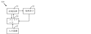
図1に示すように、本発明の第1実施例は、電子タバコ温度制御システム100を提供する。電子タバコ温度制御システム100は、給電装置11、発熱素子12、温度検出素子13及びコントローラ14を備える。給電装置11は、発熱素子12とコントローラ14とにそれぞれ電気的に接続されている。温度検出素子13は、コントローラ14に電気的に接続されている。発熱素子12は、給電装置11により電気的に駆動された後、タバコリキッド、タバコクリーム又は刻みタバコを加熱して、煙霧を生成して、ユーザに喫煙を体験させる。
As shown in FIG. 1, the first embodiment of the present invention provides an electronic cigarette
温度検出素子13は、発熱素子12の温度Tの変化を感知する。温度検出素子13の温度tは、発熱素子12の温度Tの上昇に伴って上昇して、温度検出素子13の関連物理量xの変化を引き起こす。コントローラ14は、関連物理量xを検出して、発熱素子12の温度Tを算出することができる。
The
温度検出素子13は、電子タバコ内に設置される。好ましくは、温度検出素子13は、発熱素子12に近接して設置されている。温度検出素子13は、PTCサーミスタ、NTCサーミスタ、バイメタル片、熱電対、水晶温度センサ、光ファイバ温度センサ、赤外温度センサ及びP-N接合温度センサからなる群より選ばれる1種、2種又は2種以上の任意の組み合わせであってもよい。温度検出素子13の数は、1つ、2つ又は複数であってもよい。空間が十分である場合、複数の同じ種類及び/又は異なる種類の温度検出素子13を異なる位置に設置してもよい。一方では、各温度検出素子13により発熱素子の温度Tをそれぞれ算出し、且つ平均値を算出することができる。当該平均値は、発熱素子の温度Tをさらに正確的に反映し得るものである。他方では、ある温度検出素子が故障した場合に、コントローラ14は、タイムリーに判断を下し、信頼できない値を取り除くことができる。これにより、電子タバコ温度制御システム100は、依然として正常に動作して、高い温度制御精度を確保することができる。
The
温度検出素子13の異なりに応じて、前記関連物理量xは、温度t、抵抗、電圧、電流、共振周波数、光パワー等からなる群より選ばれる1種、2種又は2種以上の組み合わせであってもよい。
Depending on the
コントローラ14は、先ず温度検出素子13の関連物理量xに基づき、温度検出素子13の温度tを算出し、その後、温度検出素子13の温度tに基づき、発熱素子12の温度Tを算出し、最後に、発熱素子12の温度Tを動作温度上限TH及び動作温度下限TLと比較して、比較結果に基づいて給電装置11から発熱素子12への出力電圧/電力を制御する。
The
図2に示すように、当該具体的な実施例において、温度検出素子13は、PTCサーミスタRTである。発熱素子12の温度Tの上昇に伴い、温度検出素子13の温度tも上昇して、さらに温度検出素子13の抵抗値RTの上昇を引き起こす。即ち、本実施例において、温度検出素子13の前記関連物理量xは、抵抗値RTである。
As shown in FIG. 2, in the specific embodiment, the
さらに、温度検出素子13の抵抗値RTを便利に測定するために、温度検出素子13を1つの固定値抵抗R5に直列に接続することが好ましい。R5の両端の電圧がVe−Vfであるので、R5を流れる電流は、(Ve−Vf)/R5である。温度検出素子13の両端の電圧がVfであるので、RT=R5*Vf/(Ve−Vf)である。
Furthermore, in order to conveniently measure the resistance R T of the
具体的には、前記コントローラ14は、順次に電気的に接続された検出ユニット141、演算ユニット142及び制御ユニット143を備える。検出ユニット141は、温度検出素子13に電気的に接続されて、温度検出素子13の両端の電圧Vfを検出し、且つ当該Vfを演算ユニット142にフィードバックする。演算ユニット142には、演算式RT=R5*Vf/(Ve−Vf)、温度検出素子13の抵抗値RTとその温度tとの対応関係データ、及び演算式T=t+Δt(Δt:実験により得られた温度検出素子13の温度tと発熱素子12の温度Tとの差の値)が予め記憶されている。演算ユニット142は、先ず、演算式RT=R5*Vf/(Ve−Vf)に基づき、温度検出素子13の抵抗値RTを算出し、次に、温度検出素子13の抵抗値RTとその温度tとの対応関係データに基づいて温度検出素子13温度tを得て、その後、式T=t+Δtに基づいて発熱素子12の温度Tを算出し、最後に、発熱素子12の温度Tを制御ユニット143にフィードバックする。制御ユニット143は、発熱素子12の温度Tを、予め記憶された動作温度上限TH及び動作温度下限TLと比較し、且つ比較結果に基づいてDC/DC電源112から発熱素子12への出力電圧/電力を制御する。
Specifically, the
さらに、給電装置11は、電池111と、電池111にそれぞれ電気的に接続されたDC/DC電源112、電圧安定化回路113と、を備える。電池111は、充電可能であり、十分な電気エネルギーを蓄積して、DC/DC電源112及び電圧安定化回路113にそれぞれ電力を提供することができる。DC/DC電源112は、発熱素子12に電気的に接続されて、電池111の電圧を上昇させた後に、発熱素子12に供電する。電圧安定化回路113は、コントローラ14に電気的に接続されて、コントローラ14に安定した電圧Veを供給する。本実施例において、電池111は、リチウムイオン電池である。しかし、他の実施例において、実際の状況に応じて、DC/DC電源112及び電圧安定化回路113を省略するか又は他の回路を用いて、DC/DC電源112及び/又は電圧安定化回路113を取り替えることができる。
Furthermore, the power supply apparatus 11 includes a battery 111, a DC /
図3に示すように、本発明の電子タバコ温度制御システム100は動作中に下記のステップを含む。
ステップS101において、コントローラ14は、温度検出素子13の関連物理量xを検出して、ステップS102に移る。
ステップS102において、コントローラ14は、温度検出素子13の関連物理量xに基づいて、発熱素子12の温度Tを算出した後に、ステップS103に移る。
ステップS103において、コントローラ14は、発熱素子12の温度Tを動作温度上限TH及び動作温度下限TLと比較する。T>THであれば、ステップS104に移り、T<TLであれば、ステップS106に移る。
ステップS104において、コントローラ14は、発熱素子12への出力電圧/電力を低減させるように給電装置11を制御し、その後、ステップS105に移る。
ステップS105において、発熱素子12は、当該出力電圧/電力の下で、一定期間動作した後に、ステップS102に戻り、且つその後の過程を繰り返す。本実施例において、前記一定期間は、1秒であってもよい。
ステップS106において、コントローラ14は、給電装置11から発熱素子12への出力電圧/電力が最大出力電圧/電力に達したかどうかを判断する。判断結果がYESであれば、ステップS107に移り、判断結果がNOであれば、ステップS108に移る。
ステップS107において、コントローラ14は、発熱素子12への出力電圧/電力を維持するように給電装置11を制御し、その後、ステップS105に移る。
ステップS108において、コントローラ14は、発熱素子12への出力電圧/電力を増大させるように給電装置11を制御し、その後、ステップS105に移る。
As shown in FIG. 3, the electronic cigarette
In step S101, the
In step S102, the
In step S103, the
In step S104, the
In step S105, the
In step S <b> 106, the
In step S107, the
In step S108, the
本発明の他の実施例において、電子タバコ温度制御システム100に対して、発熱素子の温度T、電池電量、動作電圧、出力電力等の電子タバコ動作状態に関連する情報を表示するための表示モジュールをさらに追加してもよい。
In another embodiment of the present invention, a display module for displaying information related to the electronic cigarette operating state such as the temperature T of the heating element, the battery power, the operating voltage, and the output power to the electronic cigarette
〔第2実施例〕 [Second Embodiment]
図4に示すように、本発明の第2実施例は、電子タバコ温度制御システム200を提供する。第2実施例と第1実施例との相違点は、第2実施例がコントローラ14に電気的に接続された入力装置25を追加したことにある。ユーザは、入力装置25により所望の目標温度TD(TL≦TD≦TH)を入力することができる。コントローラ14の制御下で、発熱素子12は、温度TD±Δt’を維持するように動作する。ただし、Δt’は、温度偏差を表し、給電装置11、発熱素子12、温度検出素子13及びコントローラ14の応答が一定の遅延性を有することによって発生されたものである。
As shown in FIG. 4, the second embodiment of the present invention provides an electronic cigarette
図5に示すように、本発明の電子タバコ温度制御システム200は動作中に下記のステップを含む。
ステップS201において、ユーザは、入力装置25により所望の目標温度TD(TL≦TD≦TH)を入力し、その後、ステップS202に移る。
ステップS202において、コントローラ14は、温度検出素子13の関連物理量xを検出し、その後、ステップS203に移る。
ステップS203において、コントローラ14は、発熱素子12の温度Tを算出し、その後、ステップS204に移る。
ステップS204において、コントローラ14は、発熱素子12の温度TをTDと比較する。T>TDであれば、ステップS205に移り、T<TDであれば、ステップS207に移る。
ステップS205において、コントローラ14は、発熱素子12への出力電圧/電力を低減させるように給電装置11を制御し、その後、ステップS206に移る。
ステップS206において、発熱素子12は、当該出力電圧/電力の下で一定期間動作した後、ステップS202に戻り、且つその後の過程を繰り返す。本実施例において、前記一定期間は、1秒であってもよい。
ステップS207において、コントローラ14は、給電装置11から発熱素子12への出力電圧/電力が最大出力電圧/電力に達したかどうかを判断する。判断結果がYESであれば、ステップS208に移り、判断結果がNOであれば、ステップS209に移る。
ステップS208において、コントローラ14は、発熱素子12への出力電圧/電力を維持するように給電装置11を制御し、その後、ステップS206に移る。
ステップS209において、コントローラ14は、発熱素子12への出力電圧/電力を増大させるように給電装置11を制御し、その後、ステップS206に移る。
As shown in FIG. 5, the electronic cigarette
In step S201, the user inputs a desired target temperature T D (T L ≦ T D ≦ T H ) using the
In step S202, the
In step S203, the
In step S204, the
In step S205, the
In step S206, the
In step S207, the
In step S208, the
In step S209, the
他の実施例において、ユーザがTDを入力しなければ、電子タバコ温度制御システム200の動作ステップは第1実施例と同じであり、ここで詳しい説明を省略する。
In another embodiment, if the user inputs a T D, the operation step of the electronic cigarette
また、他の実施例において、電子タバコ温度制御システム200に対して、ユーザが設定した目標温度TD、発熱素子の温度T、電池電量、動作電圧、出力電力等の電子タバコ動作状態に関連する情報を表示するための表示モジュールをさらに追加してもよい。
In another embodiment, the electronic cigarette
〔第3実施例〕 [Third embodiment]
図6に示すように、本発明の第3実施例は、電子タバコ温度制御システム300を提供する。電子タバコ温度制御システム300は、順次に電気的に接続された給電装置31、温度制御スイッチ36及び発熱素子32を備える。発熱素子32は、給電装置31により電気的駆動された後、タバコリキッド、タバコクリーム又は刻みタバコを加熱して、それに煙霧を生成させ、ユーザに喫煙を体験させる。
As shown in FIG. 6, the third embodiment of the present invention provides an electronic cigarette temperature control system 300. The electronic cigarette temperature control system 300 includes a
温度制御スイッチ36は、温度の作用下で給電装置31と発熱素子32との間の回路をオン/オフにする。発熱素子32の温度Tの上昇に伴い、温度制御スイッチ36の温度tSも上昇する。tS<TMの場合、温度制御スイッチ36は、給電装置31と発熱素子32との間の回路をオンにし、発熱素子32が正常的に動作し、発熱素子32の温度Tが上昇し、温度制御スイッチ36の温度tSも上昇する。tS>TMの場合、温度制御スイッチ36は、給電装置31と発熱素子32との間の回路をオフにし、発熱素子32が動作を停止し、発熱素子32の温度Tが自然に低下し、温度制御スイッチ36の温度tSも低下する。tS<TMになると、温度制御スイッチ36は、給電装置31と発熱素子32との間の回路を再びオンにし、発熱素子32を再び正常的に動作させる。
The temperature control switch 36 turns on / off a circuit between the
温度制御スイッチ36は、電子タバコの内部に設けられ、好ましくは、発熱素子32に近接して設けられる。温度制御スイッチ36の温度tSが発熱素子32の温度Tより少し低いことを考慮すると、温度制御スイッチ36の動作温度TMを電子タバコ温度制御システム300の動作温度上限THより少し低くさせるべきである。温度制御スイッチ36は、機械式温度制御スイッチ、電子式温度制御スイッチ及び温度制御リレーからなる群より選ばれる1種、2種又は2種以上の任意の組み合わせである。ここで、前記機械式温度制御スイッチは、蒸気圧力式温度制御スイッチ、液体膨張式温度制御スイッチ、気体吸着式温度制御スイッチ及び金属膨張式温度制御スイッチを含む。前記金属膨張式温度制御スイッチは、バイメタル片スイッチ及び記憶合金スイッチを含む。前記電子式温度制御スイッチは、抵抗式温度制御スイッチ及び熱電対式温度制御スイッチを含む。前記温度制御リレーは、サーマルリードリレーを含む。
The temperature control switch 36 is provided inside the electronic cigarette, and is preferably provided close to the
また、他の実施例において、電子タバコ温度制御システム300に対して、電池電量、動作電圧、出力電力等の電子タバコ動作状態に関する情報を表示するための表示モジュールをさらに追加してもよい。 In another embodiment, the electronic cigarette temperature control system 300 may further include a display module for displaying information related to the electronic cigarette operating state such as battery power, operating voltage, and output power.
〔第4実施例〕 [Fourth embodiment]
図7に示すように、第3実施例に比べて、本実施例は、温度制御スイッチ36に電気的に接続されたコントローラ44をさらに含むという相違点を有する。温度制御スイッチ36は、給電装置31と発熱素子32との間の回路のオン/オフを直接に制御することではなく、コントローラ44は、温度制御スイッチ36のオン/オフに基づいて判断した後に、給電装置31から発熱素子32への出力電圧/電力を制御することである。
As shown in FIG. 7, compared with the third embodiment, the present embodiment has a difference in that it further includes a controller 44 electrically connected to the temperature control switch 36. The temperature control switch 36 does not directly control the on / off of the circuit between the
発熱素子32の温度Tの上昇に伴い、温度制御スイッチ36の温度tSも上昇する。tS<TMの場合、温度制御スイッチ36は動作Aを発生し、tS>TMの場合、温度制御スイッチ36は動作Bを発生する。コントローラ44は、温度制御スイッチ36の動作を検出し、且つ動作の異なりに応じて給電装置41から発熱素子32への出力電圧/電力を制御する。ここで、動作Aは、温度制御スイッチ36のオンであってもよいし、温度制御スイッチ36のオフであってもよい。動作Bは、動作Aと逆である。
As the temperature T of the
電子タバコ温度制御システム400は、下記の有益な効果を有する。 The electronic cigarette temperature control system 400 has the following beneficial effects.
(1)下記の2つの性質の温度制御スイッチを用いることができる。1つの性質に関しては、tS<TMの場合、温度制御スイッチがオンになり、tS>TMの場合、温度制御スイッチがオフになる。もう1つの性質に関しては、tS<TMである場合、温度制御スイッチがオフになり、tS>TMである場合、温度制御スイッチがオンになる。 (1) A temperature control switch having the following two properties can be used. Regarding one property, if t S <T M , the temperature control switch is turned on, and if t S > T M , the temperature control switch is turned off. Regarding another property, if t S <T M , the temperature control switch is turned off, and if t S > T M , the temperature control switch is turned on.
(2)コントローラ44は、給電装置31の出力電圧/電力を調節して、温度Tの変動を小さくして、食感を維持することができる。これにより、温度が高すぎる時に、発熱素子32が直ちに動作を停止してしまうことによって、発熱素子32の温度Tの低下が速すぎて、ユーザの使用に影響を与えることを避けることができる。
(2) The controller 44 can maintain the texture by adjusting the output voltage / power of the
図8に示すように、本発明の電子タバコ温度制御システム400は動作中に下記のステップを含む。
ステップS401において、コントローラ44は、温度制御スイッチ36の動作に基づき、温度制御スイッチ36の温度tSとその動作温度TMとの関係を判断する。tS>TMであれば、ステップS402に移る。tS<TMであれば、ステップS404に移る。
ステップS402において、コントローラ44は、発熱素子32への出力電圧/電力を低減させるように給電装置31を制御し、その後、ステップS403に移る。
ステップS403において、発熱素子32は、当該出力電圧/電力の下で、一定期間動作した後、ステップS401に戻り、その後の過程を繰り返す。本実施例において、前記一定期間は、1秒であってもよい。
ステップS404において、コントローラ44は、給電装置31から発熱素子32への出力電圧/電力が最大出力電圧/電力に達したかどうかを判断する。判断結果がYESであれば、ステップS405に移り、判断結果がNOであれば、ステップS406に移る。
ステップS405において、コントローラ44は、発熱素子32への出力電圧/電力を維持するように給電装置31を制御し、その後、ステップS403に移る。
ステップS406において、コントローラ44は、発熱素子32への出力電圧/電力を増大させるように給電装置31を制御し、その後、ステップS403に移る。
As shown in FIG. 8, the electronic cigarette temperature control system 400 of the present invention includes the following steps during operation.
In step S401, the controller 44 determines the relationship between the temperature t S of the temperature control switch 36 and the operating temperature T M based on the operation of the temperature control switch 36. If t S > T M , the process proceeds to step S402. If t S <T M , the process proceeds to step S404.
In step S402, the controller 44 controls the
In step S403, the
In step S404, the controller 44 determines whether or not the output voltage / power from the
In step S405, the controller 44 controls the
In step S406, the controller 44 controls the
他の実施例において、電子タバコ温度制御システム400に対して、電池電量、動作電圧、出力電力等の電子タバコ動作状態に関する情報を表示するための表示モジュールをさらに追加してもよい。 In another embodiment, the electronic cigarette temperature control system 400 may further include a display module for displaying information related to the electronic cigarette operating state such as battery power, operating voltage, and output power.
〔第5実施例〕 [Fifth embodiment]
図9に示すように、本発明の第5実施例は、給電装置51、発熱素子52及びコントローラ54を備える電子タバコ温度制御システム500を提供する。給電装置51は、発熱素子52及びコントローラ54にそれぞれ電気的に接続されている。発熱素子52は、コントローラ54に電気的に接続されている。発熱素子52が給電装置51により電気的駆動された後、タバコリキッド、タバコクリーム又は刻みタバコを加熱して煙霧を生成して、ユーザに喫煙を体験させる。
As shown in FIG. 9, the fifth embodiment of the present invention provides an electronic cigarette
発熱素子52は、発熱素子として動作すると共に、温度検出素子としても動作する。発熱素子52は、抵抗温度係数特性を有する材料により作製され、白金、銅、ニッケル、チタン、鉄、セラミックス基PTC材料、高分子基PTC材料からなる群より選ばれる1種、2種又は2種以上のものにより作製されてもよく、その抵抗値RLが発熱素子52の温度Tの上昇に伴って増大する。
The
コントローラ54内には、動作温度上限TH、動作温度下限TL及び発熱素子52の抵抗値RLと発熱素子52の温度Tとの対応関係データが予め記憶されている。コントローラ54は、発熱素子52の抵抗値RLに応じて、発熱素子52の温度Tを得り、さらに発熱素子52の温度Tを動作温度上限TH及び動作温度下限TLと比較し、且つ比較結果に基づいて給電装置51から発熱素子52への出力電圧/電力を制御する。
In the
図10は、本発明の第5実施例の1種の具体的な回路図を示している。 FIG. 10 shows one specific circuit diagram of the fifth embodiment of the present invention.
具体的には、給電装置51は、電池511と、電池511にそれぞれ電気的に接続されたDC/DC電源512、電圧安定化回路513と、を備える。電池511は、充電可能であり、十分な電気エネルギーを蓄積して、使用時にDC/DC電源512及び電圧安定化回路513にそれぞれ電力を供給する。電圧安定化回路513は、コントローラ54に電気的に接続されて、コントローラ54に安定した電圧を供給する。本実施例において、電池511は、リチウムイオン電池である。勿論、他の実施例において、実際の状況に応じて、DC/DC電源512及び電圧安定化回路513を省略できるか又は他の回路を用いてDC/DC電源512及び電圧安定化回路513を取り替えることができる。
Specifically, the
電子タバコ温度制御システム500は、給電装置51と発熱素子52との間に設置された第一固定値抵抗R1をさらに備える。第一固定値抵抗R1は、発熱素子52の抵抗値RLの算出を補助するためのものである。本実施例において、第一固定値抵抗R1は、DC/DC電源512と発熱素子52との間に設置されている。DC/DC電源512は、コントローラ54の制御下で、第一固定値抵抗R1及び発熱素子52に一定の電圧Vaを供給する。発熱素子52の両端の電圧は、Vbである。したがって、発熱素子52を流れる電流は、(Va−Vb)/R1であり、発熱素子52の抵抗値RLは、RL=R1*Vb/(Va−Vb)を満足する。
The electronic cigarette
さらに、第一固定値抵抗R1の抵抗値が比較的に小さいため、第一固定値抵抗R1の両端の電圧Va−Vbは、小さくて、測定し難い。第一固定値抵抗R1の抵抗値を大きくすれば、発熱素子52の両端の電圧Vbは低下する。これによって、発熱素子52の発熱電力は、低下してしまう。第一固定値抵抗R1の両端の電圧Va−Vbの測定を便利にするために、電子タバコ温度制御システム500は、第二固定値抵抗R2、増幅器57、第三固定値抵抗R3及び第四固定値抵抗R4をさらに備える。第一固定値抵抗R1は、順次に直列に接続された第二固定値抵抗R2、増幅器57及び第三固定値抵抗R3の全体と並列に接続されている。第四固定値抵抗R4は、増幅器57に並列に接続されている。増幅器57の応用特性に基づき、Va−Vb=Vc*R2/R4を得ることができる。本実施例において、増幅器57は、LT6105チップである。増幅器57の異なりに応じて、R2、R3、R4の接続方式も異なり、又はR2、R3、R4のうちの少なくとも1つを省略してもよく、さらに必要に応じて他の電子素子を追加する可能性もある。
Furthermore, since the resistance value of the first fixed value resistor R 1 is relatively small, the voltage V a -V b across the first fixed value resistor R 1 is small and difficult to measure. The larger the first fixed value resistance value of the resistor R 1, the voltage V b across the
具体的には、コントローラ54は、順次に電気的に接続された検出ユニット541、演算ユニット542及び制御ユニット543を備える。検出ユニット541は、第四固定値抵抗R4に電気的に接続されて、第四固定値抵抗R4の両端の電圧Vcを検出し、且つVcを演算ユニット542にフィードバックする。演算ユニット542には、演算式Va−Vb=Vc*R2/R4、演算式RL=R1*Vb/(Va−Vb)及び発熱素子52の抵抗値RLと発熱素子52の温度Tとの対応関係データが予め記憶されている。演算ユニット542は、先ず増幅器の応用特性に応じて、式Va−Vb=Vc*R2/R4から第一固定値抵抗R1の両端の電圧Va−Vbを算出し、次に、式RL=R1*Vb/(Va−Vb)から発熱素子52の抵抗値RLを算出し、その後、予め記憶された発熱素子52の抵抗値RLと発熱素子52の温度Tとの対応関係データに基づいて発熱素子52の温度Tを得り、最後に、発熱素子52の温度Tを制御ユニット543にフィードバックする。制御ユニット543は、発熱素子52の温度Tを、予め記憶された動作温度上限TH及び動作温度下限TLと比較して、比較結果に基づき、DC/DC電源512から発熱素子52への出力電圧/電力を制御する。
Specifically, the
図11に示すように、本発明の電子タバコ温度制御システム500は動作中に下記のステップを含む。
ステップS501において、コントローラ54は、発熱素子52の抵抗値RLを算出し、その後、ステップS502に移る。
ステップS502において、ユーザが点火した後、コントローラ54は、発熱素子52の抵抗値RLを再び算出し、その後、ステップS503に移る。
ステップS503において、コントローラ54は、ステップS501及びステップS502の算出結果に基づき、発熱素子52が抵抗温度係数特性を有するかどうかを判断する。二回の計算結果にはほぼ差別がない又は両者の差異値が固定値抵抗の許容範囲内にあれば、発熱素子は抵抗温度係数特性を有さない。二回の計算結果の差異値が大きければ、発熱素子は抵抗温度係数特性を有する。判断結果がYESであれば、ステップS504に移り、判断結果がNOであれば、ステップS510に移る。
ステップS504において、コントローラ54は、ユーザが温度制御モードを選択したかどうかを判断する。判断結果がYESであれば、ステップS505に移り、判断結果がNOであれば、ステップS510に移る。
ステップS505において、コントローラ54は、発熱素子52の抵抗値RLを算出し、その後、ステップS506に移る。
ステップS506において、コントローラ54は、発熱素子52の抵抗値RLに基づき、発熱素子52の温度Tを算出し、その後、ステップS507に移る。
ステップS507において、コントローラ54は、発熱素子52の温度Tを、動作温度上限TH及び動作温度下限TLと比較する。T>THであれば、ステップS508に移り、T<TLであれば、ステップS511に移る。
ステップS508において、コントローラ54は、発熱素子52への出力電圧/電力を低減させるように給電装置51を制御し、その後、ステップS509に移る。
ステップS509において、発熱素子52は、当該出力電圧/電力の下で、一定期間動作した後、ステップS505に戻り、その後の過程を繰り返す。本実施例において、前記一定期間は、1秒であってもよい。
ステップS510において、コントローラ54は、給電装置51から発熱素子52への定電圧/出力電力を自動的に制御するか、又はユーザが適切な出力電圧/電力を手動的に選択する。
ステップS511において、コントローラ54は、出力電圧/電力が最大出力電圧/電力に達したかどうかを判断する。判断結果がYESであれば、ステップS512に移り、判断結果がNOであれば、ステップS513に移る。
ステップS512において、コントローラ54は、発熱素子52への出力電圧/電力を維持するように給電装置51を制御し、その後、ステップS509に移る。
ステップS513において、コントローラ54は、発熱素子52への出力電圧/電力を増大させるように給電装置51を制御し、その後、ステップS509に移る。
As shown in FIG. 11, the electronic cigarette
In step S501, the
In step S502, after the user ignites, the
In step S503, the
In step S504, the
In step S505, the
In step S506, the
In step S507, the
In step S508, the
In step S509, the
In step S510, the
In step S511, the
In step S512, the
In step S513, the
他の実施例において、電子タバコ温度制御システム500に対して、発熱素子の温度T、電池電量、動作電圧、出力電力等の電子タバコ動作状態に関する情報を表示するための表示モジュールをさらに追加してもよい。
In another embodiment, the electronic cigarette
〔第6実施例〕 [Sixth embodiment]
図12に示すように、本発明の第6実施例は、電子タバコ温度制御システム600を提供する。第5実施例に比べて、第6実施例は、コントローラ54に電気的に接続された入力装置65をさらに含むという相違点がある。ユーザは、入力装置65により所望の目標温度TD(TL≦TD≦TH)を入力することができる。コントローラ54の制御下で、発熱素子52は温度TD±Δt’を維持するように動作する。ただし、Δt’は、温度偏差を表し、給電装置51、発熱素子52、温度検出素子53及びコントローラ54の応答が一定の遅延性を有することによって発生されたものである。
As shown in FIG. 12, the sixth embodiment of the present invention provides an electronic cigarette temperature control system 600. Compared to the fifth embodiment, the sixth embodiment is different in that it further includes an input device 65 electrically connected to the
図13に示すように、本発明の電子タバコ温度制御システム600は動作中に下記のステップを含む。
ステップS601において、コントローラ54は、発熱素子52の抵抗値RLを算出し、その後、ステップS602に移る。
ステップS602において、ユーザが点火した後、コントローラ54は、発熱素子52の抵抗値RLを再び算出し、その後、ステップS603に移る。
ステップS603において、コントローラ54は、ステップS601及びステップS602の計算結果に基づき、発熱素子52が抵抗温度係数特性を有するかどうかを判断する。二回の計算結果にはほぼ差がないか又は両者の差異値が固定値抵抗の許容範囲内にあれば、発熱素子は抵抗温度係数特性を有さない。二回の計算結果の差異値が大きければ、発熱素子は抵抗温度係数特性を有する。判断結果がYESであれば、ステップS604に移り、判断結果がNOであれば、ステップS610に移る。
ステップS604において、ユーザは、入力装置65により所望の目標温度TD(TL≦TD≦TH)を入力し、その後、ステップS605に移る。
ステップS605において、コントローラ54は、発熱素子52の抵抗値RLを算出し、その後、ステップS606に移る。
ステップS606において、コントローラ54は、発熱素子52の抵抗値RLに基づき、発熱素子52の温度Tを算出し、その後、ステップS607に移る。
ステップS607において、コントローラ54は、発熱素子52の温度TとTDとを比較する。T>TDであれば、ステップS608に移り、T<TDであれば、ステップS611に移る。
ステップS608において、コントローラ54は、発熱素子52への出力電圧/電力を低減させるように給電装置51を制御し、その後、ステップS609に移る。
ステップS609において、発熱素子52は、当該出力電圧/電力の下で一定期間動作した後、ステップS605に戻り、その後の過程を繰り返す。本実施例において、前記一定期間は、1秒であってもよい。
ステップS610において、コントローラ54は、給電装置51から発熱素子52への定電圧/出力電力を自動的に制御するか又はユーザが適切な出力電圧/電力を手動的に選択する。
ステップS611において、コントローラ54は、出力電圧/電力が最大出力電圧/電力に達したかどうかを判断する。判断結果がYESであれば、ステップS612に移り、判断結果がNOであれば、ステップS613に移る。
ステップS612において、コントローラ54は、発熱素子52への出力電圧/電力を維持するように給電装置51を制御し、その後、ステップS609に移る。
ステップS613において、コントローラ54は、発熱素子52への出力電圧/電力を増大させるように給電装置51を制御し、その後、ステップS609に移る。
As shown in FIG. 13, the electronic cigarette temperature control system 600 of the present invention includes the following steps during operation.
In step S601, the
In step S602, after the user ignites, the
In step S603, the
In step S604, the user inputs a desired target temperature T D (T L ≦ T D ≦ T H ) using the input device 65, and then proceeds to step S605.
In step S605, the
In step S606, the
In step S607, the
In step S608, the
In step S609, the
In step S610, the
In step S611, the
In step S612, the
In step S613, the
他の実施例において、ユーザがTDを入力しないと、電子タバコ温度制御システム600の動作ステップは第5実施例と同じであり、ここで詳しい説明を省略する。 Those in other embodiments, the user does not enter the T D, the operation step of the electronic cigarette temperature control system 600 is the same as that of the fifth embodiment, here detailed description.
また、他の実施例において、電子タバコ温度制御システム600に対して、ユーザが設定した目標温度TD、発熱素子の温度T、電池電量、動作電圧、出力電力等の電子タバコ動作状態に関する情報を表示するための表示モジュールをさらに追加してもよい。 In another embodiment, the electronic cigarette temperature control system 600 is provided with information on the electronic cigarette operation state such as the target temperature T D set by the user, the temperature T of the heating element, the battery power, the operating voltage, and the output power. A display module for displaying may be further added.
〔第7実施例〕 [Seventh embodiment]
図14に示すように、本発明の第7実施例は、電子タバコ温度制御システム700を提供する。第7実施例と第1実施例との相違点は、第実施例7が給電装置11と発熱素子12との間に温度制御スイッチ76を追加することにある。温度制御スイッチ76は、温度の作用下で、給電装置と発熱素子との間の回路をオン/オフにするために用いられる。温度制御スイッチ76は、電子タバコ内に設置されており、好ましくは、発熱素子12に近接して設置される。温度制御スイッチ76の温度tSが発熱素子12の温度Tより少し低いことを考慮すると、温度制御スイッチ76の動作温度TMを電子タバコ温度制御システム700の動作温度上限THより少し低くさせるべきである。温度制御スイッチ76は、機械式温度制御スイッチ、電子式温度制御スイッチ及び温度制御リレーからなる群より選ばれる1種、2種又は2種以上の任意の組み合わせである。ここで、前記機械式温度制御スイッチは、蒸気圧力式温度制御スイッチ、液体膨張式温度制御スイッチ、気体吸着式温度制御スイッチ及び金属膨張式温度制御スイッチを含む。前記金属膨張式温度制御スイッチは、バイメタル片スイッチ及び記憶合金スイッチを含む。前記電子式温度制御スイッチは、抵抗式温度制御スイッチ及び熱電対式温度制御スイッチを含む。前記温度制御リレーは、サーマルリードリレーを含む。
As shown in FIG. 14, the seventh embodiment of the present invention provides an electronic cigarette
温度制御スイッチ76の温度tS<TMである場合、電子タバコ温度制御システム700の動作ステップは第1実施例と同じであり、ここで詳しい説明を省略する。温度制御スイッチ76の温度tS>TMである場合、温度制御スイッチ76はオフされ、給電装置11は発熱素子12への給電を停止し、発熱素子12の温度Tは自然に低下し、温度制御スイッチ76の温度tSも低下し、tS<TMとなると、温度制御スイッチ76は、給電装置11と発熱素子12との間の回路を再びオンにして、発熱素子12を再び第1実施例に記載のステップに従って正常的に動作させる。これにより、二重温度制御保護の効果を奏することができ、特に温度検出素子13及び/又はコントローラ14が故障した場合でも、発熱素子12の温度に対して適当に制御することができる。
When the temperature t S <T M of the temperature control switch 76, the operation steps of the electronic cigarette
他の実施例において、第2実施例は、第7実施例を参考にして、同じ改良を行ってもよい。給電装置21と発熱素子22との間に温度制御スイッチを追加することによって、二重温度制御保護の効果を奏することができる。 In other embodiments, the second embodiment may make the same improvements with reference to the seventh embodiment. By adding a temperature control switch between the power feeding device 21 and the heating element 22, the effect of double temperature control protection can be achieved.
また、他の実施例において、第5実施例と第6実施例は、第7実施例を参考にして、対応的に改良することができる。例えば、給電装置と発熱素子との間に温度制御スイッチを設ける。発熱素子が抵抗温度係数特性を有する場合、二重温度制御保護の効果を奏することができる。発熱素子が抵抗温度係数特性を有さない場合、電子タバコ温度制御システムの動作ステップは第1実施例と同じであり、ここで詳しい説明を省略する。 In other embodiments, the fifth and sixth embodiments can be improved correspondingly with reference to the seventh embodiment. For example, a temperature control switch is provided between the power feeding device and the heating element. When the heating element has a resistance temperature coefficient characteristic, the effect of double temperature control protection can be obtained. When the heating element does not have a resistance temperature coefficient characteristic, the operation steps of the electronic cigarette temperature control system are the same as those in the first embodiment, and detailed description thereof is omitted here.
〔第8実施例〕 [Eighth embodiment]
図15に示すように、本発明の第8実施例は、電子タバコ温度制御システム800を提供する。第5実施例に比べて、本実施例は、コントローラ54に電気的に接続された温度検出素子83が追加されている。発熱素子52が抵抗温度係数特性を有する場合、第5実施例の方式を参照して温度制御を実現することができる。発熱素子52が抵抗温度係数特性を有さない場合、第1実施例の方式を参照して温度制御を実現することができる。これに代えて、温度制御スイッチをコントローラに電気的に接続することができ、発熱素子52が抵抗温度係数特性を有さない場合、第4実施例の方式を参照して温度制御を実現することができる。
As shown in FIG. 15, the eighth embodiment of the present invention provides an electronic cigarette
本発明の電子タバコ温度制御システム800は、下記の有益な効果を奏することができる。ユーザが抵抗温度係数特性を有する発熱素子の霧化装置を使用する場合、第5実施例の方式に従って温度制御を実現することができる。ユーザが抵抗温度係数特性を有さない発熱素子の霧化装置を使用する場合、第1実施例に従って温度制御を実現する。勿論、第4実施例の方式に従って、温度制御も実現することができる。このように、電子タバコ温度制御システム及びこれを備える電子タバコの汎用性を増加することができる。
The electronic cigarette
他の実施例において、二重温度制御保護の作用を果たすために、給電装置51と発熱素子52との間に温度制御スイッチを追加することができ、特に、温度検出素子83及び/又はコントローラ54が故障した時に、発熱素子52の温度を一定の程度制御することができる。
In other embodiments, a temperature control switch can be added between the
〔第9実施例〕 [Ninth embodiment]
図16に示すように、本発明の第9実施例は、電子タバコ温度制御システム900を提供する。第6実施例に比べて、本実施例は、コントローラ64に電気的に接続された温度検出素子93が追加されている。発熱素子62が抵抗温度係数特性を有する場合、第6実施例の方式を参照して、発熱素子62が目標温度TD±Δt’の下でて動作することを実現することができる。発熱素子62が抵抗温度係数特性を有さない場合、第2実施例の方式を参照して、発熱素子62が目標温度TD±Δt’の下で動作することを実現することができる。
As shown in FIG. 16, the ninth embodiment of the present invention provides an electronic cigarette temperature control system 900. Compared with the sixth embodiment, the present embodiment is further provided with a
他の実施例において、給電装置61と発熱素子62との間に温度制御スイッチを追加することによって、二重温度制御保護の作用を果たすことができる。 In another embodiment, a dual temperature control protection function can be achieved by adding a temperature control switch between the power feeding device 61 and the heating element 62.
〔第10実施例〕 [Tenth embodiment]
図17に示すように、本発明に係る電子タバコは、ケース101、吸口102、貯液チャンバ103、液体伝導素子104及び電子タバコ温度制御システム100を備える。電子タバコ温度制御システム100は、液体伝導素子104を介して貯液チャンバ103に連通され、これにより、タバコリキッドを加熱してそれを霧化させ、且つ発熱素子12の温度を合理的な範囲内にするように制御する。
As shown in FIG. 17, the electronic cigarette according to the present invention includes a
勿論、電子タバコ温度制御システム100は、第2実施例から第9実施例までの何れか1つの電子タバコ温度制御システム(200、300、400、500、600、700、800、900)により取り替えられ、又は第1実施例から第9実施例までの何れか1つの電子タバコ温度制御システム(100、200、300、400、500、600、700、800、900)に基づいて改良して得られた電子タバコ温度制御システムにより取り替えられることができる。
Of course, the electronic cigarette
また、第1実施例から第9実施例までの何れか1つの電子タバコ温度制御システム及び第1実施例から第9実施例までの何れか1つの電子タバコ温度制御システムに基づいて改良された電子タバコ温度制御システムは、電子タバコの液体伝導方式、霧化方式、霧化材質の種類(例えば、刻みタバコ、タバコオイル又はタバコクリーム)、加熱方式などに限定されることがなく、任意の電子タバコに適用することが可能である。 Further, an electronic device improved based on any one electronic cigarette temperature control system from the first embodiment to the ninth embodiment and any one electronic cigarette temperature control system from the first embodiment to the ninth embodiment. The cigarette temperature control system is not limited to the electronic cigarette liquid conduction method, atomization method, type of atomization material (for example, chopped tobacco, tobacco oil or tobacco cream), heating method, etc. It is possible to apply to.
100、200、300、400、500、600、700、800、900 電子タバコ温度制御システム
11、31、51 給電装置
111、511 電池
112、512 DC/DC電源
113、513 電圧安定化回路
12、32、52 発熱素子
13、83、93 温度感知回路
14、44、54 コントローラ
141、541 検出ユニット
142、542 演算ユニット
143、543 制御ユニット
25、65 入力装置
36、76 温度制御スイッチ
57 増幅器
10 電子タバコ
101 ケース
102 吸口
103 貯液チャンバ
104 液体伝導素子
100, 200, 300, 400, 500, 600, 700, 800, 900 Electronic cigarette
Claims (10)
前記給電装置は、前記発熱素子と前記コントローラとにそれぞれ電気的に接続され、前記温度検出素子は、前記コントローラに電気的に接続されて、前記コントローラは、点火前に発熱素子の抵抗値R L を算出し、点火した後、発熱素子の抵抗値R L を再び算出し、前記コントローラは、更に、この2回の算出結果に基づき、発熱素子が抵抗温度係数特性を有するかどうかを判断し、
前記発熱素子が抵抗温度係数特性を有さないとき、前記温度検出素子は、前記発熱素子の温度Tの変化を感知し、且つ温度Tの変化を前記コントローラにフィードバックし、前記コントローラは、前記温度検出素子の関連物理量xに基づき、前記温度検出素子の温度tを算出し、さらに前記温度検出素子の温度tから前記発熱素子の温度Tを算出し、
前記コントローラは、更に、前記発熱素子の温度Tを動作温度上限T H 及び動作温度下限T L と比較し、且つ比較結果に基づき、前記給電装置から前記発熱素子への出力電圧/電力を制御することを特徴とする電子タバコ温度制御システム。 An electronic cigarette temperature control system including a power feeding device, a heating element, a temperature detection element, and a controller,
The power feeding device is electrically connected to the heating element and the controller, the temperature detection element is electrically connected to the controller, and the controller has a resistance value R L of the heating element before ignition. After the ignition, the resistance value RL of the heating element is calculated again, and the controller further determines whether the heating element has a resistance temperature coefficient characteristic based on the two calculation results,
When the heating element does not have a resistance temperature coefficient characteristic, the temperature detection element senses a change in the temperature T of the heating element and feeds back a change in the temperature T to the controller. Based on the related physical quantity x of the detection element, calculate the temperature t of the temperature detection element, and further calculate the temperature T of the heating element from the temperature t of the temperature detection element ,
The controller further compares the temperature T of the heating element with an operating temperature upper limit TH and an operating temperature lower limit TL , and controls the output voltage / power from the power feeding device to the heating element based on the comparison result. An electronic cigarette temperature control system characterized by that.
前記検出ユニットは、前記温度検出素子に電気的に接続されて、前記温度検出素子の両端の電圧Vfを検出し、且つこのVfを前記演算ユニットにフィードバックし、
前記演算ユニットには、演算式RT=R5*Vf/(Ve−Vf)、前記温度検出素子の抵抗値RTと前記温度検出素子の温度tとの対応関係データ及び演算式T=t+Δtが予め記憶されており、前記演算ユニットは、予め記憶された演算式及び対応関係データに基づいて前記発熱素子の温度Tを算出し、且つ温度Tを前記制御ユニットにフィードバックし、
前記制御ユニットは、前記発熱素子の温度Tを予め記憶された動作温度上限TH及び動作温度下限TLと比較し、且つ比較結果に基づき、前記給電装置から前記発熱素子への出力電圧/電力を制御することを特徴とする請求項1に記載の電子タバコ温度制御システム。 The controller includes a detection unit, a calculation unit, and a control unit, which are electrically connected in sequence,
The detection unit is electrically connected to the temperature detection element, detects a voltage V f across the temperature detection element, and feeds back this V f to the arithmetic unit.
The arithmetic unit includes an arithmetic expression R T = R 5 * V f / (V e −V f ), correspondence data between the resistance value RT of the temperature detection element and the temperature t of the temperature detection element, and an arithmetic expression T = t + Δt is stored in advance, and the arithmetic unit calculates the temperature T of the heating element based on the pre-stored arithmetic expression and correspondence data, and feeds back the temperature T to the control unit,
The control unit compares the temperature T of the heat generating element with a preliminarily stored operating temperature upper limit TH and operating temperature lower limit TL , and based on the comparison result, outputs voltage / power from the power feeding device to the heat generating element. The electronic cigarette temperature control system according to claim 1, wherein the electronic cigarette temperature control system is controlled.
前記温度制御スイッチは、前記給電装置と前記発熱素子との間に直列に接続されており、前記温度検出素子及び/又は前記コントローラが故障した時に、前記温度制御スイッチは、温度制御の役割を果たすことを特徴とする請求項1に記載の電子タバコ温度制御システム。 An electronic cigarette temperature control system further comprising a temperature control switch,
The temperature control switch is connected in series between the power supply device and the heating element, and when the temperature detection element and / or the controller fails, the temperature control switch plays a role of temperature control. The electronic cigarette temperature control system according to claim 1.
Applications Claiming Priority (3)
| Application Number | Priority Date | Filing Date | Title |
|---|---|---|---|
| CN201510033982 | 2015-01-22 | ||
| CN201510033982.9 | 2015-01-22 | ||
| PCT/CN2015/087597 WO2016115890A1 (en) | 2015-01-22 | 2015-08-20 | Temperature control system and control method thereof, and electronic cigarette containing said temperature control system |
Related Child Applications (1)
| Application Number | Title | Priority Date | Filing Date |
|---|---|---|---|
| JP2019021740A Division JP6667690B2 (en) | 2015-01-22 | 2019-02-08 | Temperature control system and its control method, electronic cigarette provided with temperature control system |
Publications (2)
| Publication Number | Publication Date |
|---|---|
| JP2018505696A JP2018505696A (en) | 2018-03-01 |
| JP6483283B2 true JP6483283B2 (en) | 2019-03-13 |
Family
ID=53087512
Family Applications (2)
| Application Number | Title | Priority Date | Filing Date |
|---|---|---|---|
| JP2017557242A Active JP6483283B2 (en) | 2015-01-22 | 2015-08-20 | Temperature control system, control method therefor, and electronic cigarette provided with temperature control system |
| JP2019021740A Active JP6667690B2 (en) | 2015-01-22 | 2019-02-08 | Temperature control system and its control method, electronic cigarette provided with temperature control system |
Family Applications After (1)
| Application Number | Title | Priority Date | Filing Date |
|---|---|---|---|
| JP2019021740A Active JP6667690B2 (en) | 2015-01-22 | 2019-02-08 | Temperature control system and its control method, electronic cigarette provided with temperature control system |
Country Status (6)
| Country | Link |
|---|---|
| US (2) | US10321718B2 (en) |
| EP (1) | EP3249488B1 (en) |
| JP (2) | JP6483283B2 (en) |
| KR (1) | KR20170107518A (en) |
| CN (4) | CN104571190B (en) |
| WO (4) | WO2016115891A1 (en) |
Families Citing this family (113)
| Publication number | Priority date | Publication date | Assignee | Title |
|---|---|---|---|---|
| EP4324352A3 (en) * | 2014-03-19 | 2024-05-22 | Philip Morris Products S.A. | Monolithic plane with electrical contacts and methods for manufacturing the same |
| EP3133942B1 (en) | 2014-04-23 | 2019-04-17 | Fontem Holdings 1 B.V. | Electronic cigarette with coil-less atomizer |
| CN104571190B (en) * | 2015-01-22 | 2017-05-10 | 卓尔悦欧洲控股有限公司 | Temperature control system and electronic cigarette thereof |
| CN104783332B (en) * | 2015-03-29 | 2018-04-03 | 昆山祥维电子科技有限公司 | A kind of electronic cigarette that can be temperature automatically controlled |
| WO2016176800A1 (en) * | 2015-05-04 | 2016-11-10 | Fontem Holdings 2 B.V. | Liquid guiding structure, coil-less heating element and power management unit for electronic cigarettes |
| CN104839896A (en) * | 2015-06-05 | 2015-08-19 | 昆山祥维电子科技有限公司 | Automatic temperature-control electronic cigarette with titanium wire |
| CN104950953A (en) * | 2015-06-09 | 2015-09-30 | 昂纳自动化技术(深圳)有限公司 | Electronic cigarette and temperature control method thereof |
| WO2016200966A1 (en) * | 2015-06-09 | 2016-12-15 | Hydra-Electric Company | Electronic temperature switch |
| CN106307614A (en) * | 2015-06-17 | 2017-01-11 | 深圳市新宜康科技有限公司 | Electronic cigarette atomization temperature control method and circuit and electronic cigarette atomization core with controllable temperature |
| CN105011375B (en) * | 2015-07-21 | 2017-12-15 | 昆山祥维电子科技有限公司 | A kind of electronic cigarette that is atomized silk resistance and can automatically control |
| TW201707587A (en) * | 2015-08-21 | 2017-03-01 | 力智電子股份有限公司 | Power control circuit and power control for electronic cigarette |
| WO2017031681A1 (en) * | 2015-08-25 | 2017-03-02 | 深圳麦克韦尔股份有限公司 | Electronic cigarette and control method therefor |
| CN105167203B (en) * | 2015-09-09 | 2016-12-07 | 深圳麦克韦尔股份有限公司 | Electronic cigarette and heating atomization control method thereof |
| CN105223986A (en) * | 2015-09-16 | 2016-01-06 | 深圳圆机科技有限公司 | Electronic cigarette atomizing temperature-controlled process, electronic cigarette, control device and system |
| WO2017076247A1 (en) * | 2015-11-04 | 2017-05-11 | 常州聚为智能科技有限公司 | Battery apparatus, electronic cigarette, and control method therefor |
| CA3005027C (en) | 2015-11-10 | 2020-07-21 | Avanzato Technology Corp. | A disposable tank and mod assembly |
| CN106820265B (en) * | 2015-12-07 | 2021-07-09 | 深圳麦克韦尔科技有限公司 | Electronic cigarette and heating atomization control method thereof |
| CN108576933B (en) * | 2015-12-09 | 2021-07-02 | 卓尔悦欧洲控股有限公司 | Control device with reminding function, electronic cigarette and control method |
| US10624392B2 (en) * | 2015-12-22 | 2020-04-21 | Altria Client Services Llc | Aerosol-generating system with motor |
| US10258087B2 (en) * | 2016-03-10 | 2019-04-16 | Altria Client Services Llc | E-vaping cartridge and device |
| US10278423B2 (en) * | 2016-03-11 | 2019-05-07 | Altria Client Services Llc | E-vaping device cartridge with internal conductive element |
| CN106072766A (en) * | 2016-04-27 | 2016-11-09 | 东莞市深溪五金电子科技有限公司 | A kind of electronic cigarette temperature control system inputting exothermic material temperature-coefficient of electrical resistance |
| EP3469930B1 (en) | 2016-06-08 | 2021-06-09 | Joyetech Europe Holding GmbH | Atomizer and electronic cigarette |
| CN105852229B (en) * | 2016-06-21 | 2019-06-21 | 湖南中烟工业有限责任公司 | A kind of electronic cigarette control system and control method |
| US10212964B2 (en) * | 2016-07-07 | 2019-02-26 | Altria Client Services | Additive assembly for electronic vaping device |
| CN106235413B (en) * | 2016-07-19 | 2018-11-09 | 卓尔悦欧洲控股有限公司 | Electronic cigarette and its temperature warning method |
| US10765146B2 (en) * | 2016-08-08 | 2020-09-08 | Rai Strategic Holdings, Inc. | Boost converter for an aerosol delivery device |
| JP6838784B2 (en) * | 2016-09-20 | 2021-03-03 | ニコベンチャーズ トレーディング リミテッド | Manufacturing method of aerosol supply device and aerosol supply device |
| US10440994B2 (en) * | 2016-11-03 | 2019-10-15 | Altria Client Services Llc | Vaporizer assembly for e-vaping device |
| US10524508B2 (en) * | 2016-11-15 | 2020-01-07 | Rai Strategic Holdings, Inc. | Induction-based aerosol delivery device |
| WO2018102703A1 (en) * | 2016-12-02 | 2018-06-07 | Vmr Products Llc | Combination vaporizer |
| US11013266B2 (en) * | 2016-12-09 | 2021-05-25 | Rai Strategic Holdings, Inc. | Aerosol delivery device sensory system including an infrared sensor and related method |
| JP7167028B2 (en) | 2016-12-27 | 2022-11-08 | ジュール・ラブズ・インコーポレイテッド | Thermal conductive core for electronic vaporizer |
| US10765148B2 (en) * | 2016-12-27 | 2020-09-08 | Altria Client Services Llc | E-vaping device including e-vaping case with sliding mechanism for initiating vapor generation |
| US10206433B2 (en) * | 2016-12-28 | 2019-02-19 | Ya-Ling Ding | Controlling method for electronic cigarette with multiple output modes and electronic cigarette |
| WO2018141101A1 (en) * | 2017-02-06 | 2018-08-09 | 东莞市深溪五金电子科技有限公司 | Electronic cigarette temperature control system for inputting temperature coefficient of resistance of heating material |
| CN107343669B (en) * | 2017-07-13 | 2018-05-04 | 深圳市赛尔美电子科技有限公司 | The puff count detection method of electronic smoking set and electronic smoking set |
| BR112019020434B1 (en) * | 2017-05-03 | 2023-10-03 | Philip Morris Products S.A | SYSTEM AND METHOD FOR TEMPERATURE CONTROL IN AN ELECTRICALLY HEATED AEROSOL GENERATING DEVICE |
| CN206819189U (en) * | 2017-06-16 | 2017-12-29 | 深圳市优维尔科技有限公司 | A kind of intelligent temperature adjusting control circuit on electronic cigarette |
| CN109407727A (en) * | 2017-08-15 | 2019-03-01 | 卓尔悦欧洲控股有限公司 | The temperature control method and its electronic cigarette of electronic cigarette |
| US11096423B2 (en) | 2017-09-25 | 2021-08-24 | Altria Client Services Llc | E-vapor device with bimetallic actuator for opening and sealing reservoir |
| JP7051349B2 (en) * | 2017-09-26 | 2022-04-11 | テルモ株式会社 | Constant power control device for tube joining device |
| KR102374086B1 (en) * | 2017-09-29 | 2022-03-14 | 주식회사 케이티앤지 | System and apparatus for generating aerosols |
| CN109820248B (en) * | 2017-11-23 | 2024-01-09 | 上海烟草集团有限责任公司 | Heating system, atomizer and electronic cigarette |
| DE102017222528B3 (en) | 2017-12-12 | 2019-01-24 | Heraeus Sensor Technology Gmbh | Heating unit for a system for providing an inhalable aerosol |
| GB201721646D0 (en) * | 2017-12-21 | 2018-02-07 | British American Tobacco Investments Ltd | Aerosol provision device |
| US11272741B2 (en) | 2018-01-03 | 2022-03-15 | Cqens Technologies Inc. | Heat-not-burn device and method |
| US10750787B2 (en) | 2018-01-03 | 2020-08-25 | Cqens Technologies Inc. | Heat-not-burn device and method |
| CN110051039B (en) * | 2018-01-19 | 2023-11-14 | 常州市派腾电子技术服务有限公司 | Temperature control method and electronic cigarette |
| CN110051041A (en) * | 2018-01-19 | 2019-07-26 | 常州市派腾电子技术服务有限公司 | Output parameter control method and electronic cigarette |
| CN108366439B (en) * | 2018-02-09 | 2021-11-16 | 张宜悦 | Constant temperature control method, heating device, and storage medium |
| KR20200123171A (en) | 2018-02-27 | 2020-10-28 | 쥴 랩스, 인크. | Mass output controlled carburetor |
| US20190274354A1 (en) * | 2018-03-09 | 2019-09-12 | Rai Strategic Holdings, Inc. | Electronically heated heat-not-burn smoking article |
| CN111936001B (en) * | 2018-03-26 | 2023-11-28 | 日本烟草产业株式会社 | Aerosol generating apparatus, control method, and program |
| CN108458804A (en) * | 2018-03-26 | 2018-08-28 | 深圳市舜宝科技有限公司 | The battery temperature detection method and device of electronic cigarette |
| KR102274250B1 (en) * | 2018-04-09 | 2021-07-07 | 주식회사 아모센스 | heater for electronic cigarette device |
| CN108618206B (en) * | 2018-04-10 | 2020-05-05 | 绿烟实业(深圳)有限公司 | Smoking set equipment and temperature measuring and controlling method for smoking set equipment |
| KR102373331B1 (en) * | 2018-05-11 | 2022-03-11 | 주식회사 이엠텍 | Method for preventing over-heating and malfunction of fine particle generator |
| CN110554719A (en) * | 2018-06-01 | 2019-12-10 | 常州市派腾电子技术服务有限公司 | Control method and device of electronic cigarette |
| WO2019246048A1 (en) * | 2018-06-18 | 2019-12-26 | Hassan Charles | Methods and systems for managing vapor distribution |
| EP3813914B1 (en) | 2018-06-26 | 2023-10-25 | Juul Labs, Inc. | Vaporizer wicking elements |
| CN110652036A (en) * | 2018-06-29 | 2020-01-07 | 筑思有限公司 | Electronic cigarette and temperature control method thereof |
| KR20200004693A (en) * | 2018-07-04 | 2020-01-14 | 주식회사 케이티앤지 | An apparatus for generating aerosols |
| KR102116118B1 (en) * | 2018-07-18 | 2020-05-27 | 주식회사 케이티앤지 | Method for controlling temperature of heater of aerosol generator and apparatus thereof |
| KR102146055B1 (en) * | 2018-07-19 | 2020-08-19 | 주식회사 케이티앤지 | Method for preventing overshoot of heater of aerosol generator and apparatus thereof |
| WO2020020970A1 (en) * | 2018-07-26 | 2020-01-30 | Jt International Sa | Aerosol generating system and device |
| CN110859331B (en) * | 2018-08-20 | 2022-04-08 | 常州市派腾电子技术服务有限公司 | Temperature control method of electronic cigarette, electronic cigarette and computer storage medium |
| CN208909131U (en) * | 2018-08-20 | 2019-05-31 | 常州市派腾电子技术服务有限公司 | Control circuit and electronic cigarette |
| JP6924904B2 (en) * | 2018-08-24 | 2021-08-25 | 日本たばこ産業株式会社 | Suction component generator, method and program to control the suction component generator |
| CN109224311B (en) * | 2018-08-29 | 2020-08-04 | 苏州医疗用品厂有限公司 | Temperature control method of specific electromagnetic wave therapeutic apparatus |
| EP3855956B1 (en) * | 2018-09-25 | 2022-09-07 | Philip Morris Products S.A. | Inductive heating assembly for inductive heating of an aerosol-forming substrate |
| JP2020058236A (en) * | 2018-10-04 | 2020-04-16 | 日本たばこ産業株式会社 | Inhalation component generating device, control circuit, and control method and control program of inhalation component generating device |
| GB2580213B (en) | 2018-10-15 | 2021-10-27 | Juul Labs Inc | Heating element |
| GB2613472B (en) * | 2018-10-19 | 2023-09-06 | Juul Labs Inc | Vaporizer power system |
| CN109691693A (en) * | 2018-12-13 | 2019-04-30 | 清华大学 | A kind of atomization method and atomizer |
| WO2020146982A1 (en) * | 2019-01-14 | 2020-07-23 | 昂纳自动化技术(深圳)有限公司 | Power supply device having temperature control function and electronic cigarette |
| US11253001B2 (en) | 2019-02-28 | 2022-02-22 | Juul Labs, Inc. | Vaporizer device with vaporizer cartridge |
| EP3834638A3 (en) * | 2019-03-11 | 2021-08-18 | Nicoventures Trading Limited | Aerosol-generating device |
| PL3711552T3 (en) | 2019-03-22 | 2023-10-23 | Imperial Tobacco Limited | Smoking substitute system |
| WO2020200271A1 (en) * | 2019-04-03 | 2020-10-08 | 深圳市合元科技有限公司 | Electric heating smoking system and release control method for volatile compound |
| JP6588669B1 (en) * | 2019-04-12 | 2019-10-09 | 日本たばこ産業株式会社 | Control device for aerosol inhaler, control method, program, aerosol inhaler |
| CN110225476A (en) * | 2019-04-29 | 2019-09-10 | 上海掌门科技有限公司 | The method and apparatus of electronic cigarette equipment and the related information for providing user |
| CN112107030B (en) * | 2019-06-04 | 2022-02-15 | 湖南中烟工业有限责任公司 | Ultrasonic atomization sheet oscillation control method and control system |
| CN110301678A (en) * | 2019-07-12 | 2019-10-08 | 深圳市福来科技有限公司 | It is a kind of not burnt the dual-temperature measure and control device and method of smoking set based on heating |
| KR102278593B1 (en) * | 2019-07-29 | 2021-07-16 | 주식회사 케이티앤지 | Aerosol generating device and operation method thereof |
| WO2021016994A1 (en) * | 2019-08-01 | 2021-02-04 | 深圳葭南科技有限公司 | Electronic cigarette control method used for better restoring taste of e-liquids and electronic cigarette |
| CN110353318B (en) * | 2019-08-20 | 2022-12-09 | 深圳迈美特科技有限公司 | Electronic cigarette and control method thereof |
| US11785991B2 (en) * | 2019-10-04 | 2023-10-17 | Rai Strategic Holdings, Inc. | Use of infrared temperature detection in an aerosol delivery device |
| CN110731545B (en) * | 2019-10-18 | 2022-12-27 | 深圳麦克韦尔科技有限公司 | Atomization assembly heating control method and device, electronic atomization device and storage medium |
| JP6667709B1 (en) * | 2019-10-24 | 2020-03-18 | 日本たばこ産業株式会社 | Power supply unit for aerosol inhaler |
| WO2021113533A1 (en) * | 2019-12-04 | 2021-06-10 | Juul Labs, Inc. | High-power drive circuit for a vaporizer heater |
| KR102318694B1 (en) * | 2019-12-18 | 2021-10-27 | 주식회사 케이티앤지 | Aerosol generating apparatus and method for measuring temperature thereof |
| EP4076067B1 (en) * | 2019-12-20 | 2023-11-15 | Philip Morris Products S.A. | Heater for aerosol-forming substrate comprising a positive temperature coefficient thermistor |
| CN111602868A (en) * | 2020-01-13 | 2020-09-01 | 勒克司国际集团 | Device for heating non-burning electronic cigarette and using method thereof |
| KR20210092082A (en) * | 2020-01-15 | 2021-07-23 | 주식회사 케이티앤지 | Aerosol generating apparatus performing heating operation automatically |
| WO2021181993A1 (en) * | 2020-03-12 | 2021-09-16 | 日本たばこ産業株式会社 | Inhaler and method for manufacturing inhaler |
| JP6886056B1 (en) * | 2020-03-12 | 2021-06-16 | 日本たばこ産業株式会社 | Controller for aspirator |
| CN111442852B (en) * | 2020-04-24 | 2023-06-13 | 云南中烟工业有限责任公司 | Device and method for detecting surface temperature of heating element in cylindrical cavity |
| WO2021250278A1 (en) * | 2020-06-13 | 2021-12-16 | Nicoventures Trading Limited | Aerosol generating device |
| CN112203368B (en) * | 2020-10-09 | 2023-05-09 | 宁波昕科工贸有限公司 | Temperature control method, circuit and heating device |
| CN112306118B (en) * | 2020-10-21 | 2022-03-22 | 深圳市博迪科技开发有限公司 | Temperature control system and control method of aerosol generating device |
| CN112656048A (en) * | 2020-12-11 | 2021-04-16 | 深圳市基克纳科技有限公司 | Method and device for automatically stopping heating of electronic cigarette |
| KR102522678B1 (en) | 2020-12-31 | 2023-04-17 | 주식회사 케이티앤지 | Aerosol generating device |
| CN112841753B (en) * | 2020-12-31 | 2022-06-07 | 四川三联新材料有限公司 | Heating element temperature control method, temperature control device and aerosol generating device |
| CN112869249A (en) * | 2021-01-12 | 2021-06-01 | 深圳市海派特光伏科技有限公司 | Test method and test system of disposable electronic cigarette |
| DE102021202544A1 (en) * | 2021-03-16 | 2022-09-22 | Alveon GmbH | evaporator device |
| DE102021202547A1 (en) * | 2021-03-16 | 2022-09-22 | Alveon GmbH | inhaler |
| KR102640829B1 (en) * | 2021-03-29 | 2024-02-23 | 주식회사 케이티앤지 | Heater for aerosol-generating apparatus and aerosol-generating apparatus including the same |
| CN113907422A (en) * | 2021-08-31 | 2022-01-11 | 深圳麦时科技有限公司 | Heating assembly, electronic atomization device and control method of heating assembly |
| WO2023073932A1 (en) | 2021-10-29 | 2023-05-04 | 日本たばこ産業株式会社 | Inhalation device, substrate, and control method |
| CN116763009A (en) * | 2022-03-11 | 2023-09-19 | 深圳市合元科技有限公司 | Electronic atomizing device and control method thereof |
| WO2024024003A1 (en) * | 2022-07-28 | 2024-02-01 | 日本たばこ産業株式会社 | Aerosol generation system, control method, and program |
| WO2024024004A1 (en) * | 2022-07-28 | 2024-02-01 | 日本たばこ産業株式会社 | Aerosol generation system, control method, and program |
Family Cites Families (39)
| Publication number | Priority date | Publication date | Assignee | Title |
|---|---|---|---|---|
| US6040560A (en) * | 1996-10-22 | 2000-03-21 | Philip Morris Incorporated | Power controller and method of operating an electrical smoking system |
| CN2789614Y (en) * | 2005-04-21 | 2006-06-21 | 许锦永 | Cigarette lighter |
| WO2007098337A2 (en) * | 2006-02-17 | 2007-08-30 | Jake Brenneise | Portable vaporizing device and method for inhalation and/or aromatherapy without combustion |
| US8182139B2 (en) | 2008-05-30 | 2012-05-22 | Apple Inc. | Calibration of temperature sensing circuitry in an electronic device |
| CN201491720U (en) * | 2009-06-05 | 2010-06-02 | 黄德 | Disposable electronic cigarette |
| JP5402744B2 (en) * | 2010-03-17 | 2014-01-29 | パナソニック株式会社 | Thermostat and seat heater provided with the same |
| US8820330B2 (en) * | 2011-10-28 | 2014-09-02 | Evolv, Llc | Electronic vaporizer that simulates smoking with power control |
| US9814262B2 (en) * | 2012-07-11 | 2017-11-14 | Sis Resources, Ltd. | Hot-wire control for an electronic cigarette |
| CN102754924B (en) * | 2012-07-31 | 2014-09-10 | 龙功运 | Evaporation type electronic cigarette |
| PL2895930T3 (en) * | 2012-09-11 | 2017-04-28 | Philip Morris Products S.A. | Device and method for controlling an electrical heater to control temperature |
| CN103404969A (en) * | 2012-10-05 | 2013-11-27 | 佛山市新芯微电子有限公司 | Electronic cigarette device |
| US9854841B2 (en) * | 2012-10-08 | 2018-01-02 | Rai Strategic Holdings, Inc. | Electronic smoking article and associated method |
| TWI608805B (en) * | 2012-12-28 | 2017-12-21 | 菲利浦莫里斯製品股份有限公司 | Heated aerosol-generating device and method for generating aerosol with consistent properties |
| CN104007775A (en) * | 2013-02-25 | 2014-08-27 | 美的集团股份有限公司 | Electrothermal equipment and voltage detection method |
| CN104026743A (en) * | 2013-03-05 | 2014-09-10 | 向智勇 | Electronic cigarette having long-time heating protecting function and protecting method thereof |
| US9423152B2 (en) * | 2013-03-15 | 2016-08-23 | R. J. Reynolds Tobacco Company | Heating control arrangement for an electronic smoking article and associated system and method |
| CN203166473U (en) * | 2013-03-20 | 2013-08-28 | 向智勇 | Overheating protective device for electronic cigarette or cartridge |
| CN103236461B (en) * | 2013-04-03 | 2016-05-25 | 友达光电股份有限公司 | Photoelectric conversion module |
| US20140299137A1 (en) * | 2013-04-05 | 2014-10-09 | Johnson Creek Enterprises, LLC | Electronic cigarette and method and apparatus for controlling the same |
| WO2014166037A1 (en) * | 2013-04-07 | 2014-10-16 | 吉瑞高新科技股份有限公司 | Electronic cigarette with controllable atomization temperature |
| WO2014166121A1 (en) * | 2013-04-12 | 2014-10-16 | Liu Shuigen | Heating apparatus with temperature control function, temperature control method, and tobacco evaporator |
| US20140338685A1 (en) * | 2013-05-20 | 2014-11-20 | Sis Resources, Ltd. | Burning prediction and communications for an electronic cigarette |
| CN103230100B (en) * | 2013-05-21 | 2016-03-02 | 广东中烟工业有限责任公司 | A kind of Novel electric cigarette |
| CN203646502U (en) * | 2013-11-28 | 2014-06-18 | 刘秋明 | Battery pack of electronic cigarette, atomization assembly of electronic cigarette, and electronic cigarette |
| CN203618784U (en) * | 2013-12-06 | 2014-06-04 | 刘秋明 | Cigarette case control circuit and electronic cigarette case |
| CN203643774U (en) * | 2013-12-13 | 2014-06-11 | 深圳市合元科技有限公司 | Electronic cigarette |
| US9549573B2 (en) * | 2013-12-23 | 2017-01-24 | Pax Labs, Inc. | Vaporization device systems and methods |
| CN203676136U (en) * | 2013-12-28 | 2014-07-02 | 黄浩 | Electronic cigarette atomizer and electronic cigarette |
| CN203851801U (en) * | 2014-01-26 | 2014-10-01 | 深圳市合元科技有限公司 | Atomizer for electronic cigarettes and electronic cigarette |
| US9597466B2 (en) * | 2014-03-12 | 2017-03-21 | R. J. Reynolds Tobacco Company | Aerosol delivery system and related method, apparatus, and computer program product for providing control information to an aerosol delivery device via a cartridge |
| CN203952441U (en) * | 2014-06-11 | 2014-11-26 | 深圳市合元科技有限公司 | Atomising device and electronic cigarette |
| CN104116138B (en) * | 2014-06-24 | 2017-10-10 | 深圳麦克韦尔股份有限公司 | Electronic cigarette and its control method |
| CN204032368U (en) * | 2014-08-07 | 2014-12-24 | 王松龄 | A kind of temperature control electronic cigarette |
| CN204070568U (en) * | 2014-08-14 | 2015-01-07 | 深圳市合元科技有限公司 | The electronic cigarette of dual power supply |
| CN204015119U (en) * | 2014-08-21 | 2014-12-17 | 葛宇 | Electronics tobacco pipe |
| CN204032680U (en) * | 2014-08-26 | 2014-12-24 | 徐孝峰 | A kind of operating desk of information technology teaching |
| GB2529629B (en) * | 2014-08-26 | 2021-05-12 | Nicoventures Trading Ltd | Electronic aerosol provision system |
| CN204682527U (en) * | 2015-01-22 | 2015-10-07 | 卓尔悦(常州)电子科技有限公司 | Temperature control system and the electronic cigarette containing temperature control system |
| CN104571190B (en) * | 2015-01-22 | 2017-05-10 | 卓尔悦欧洲控股有限公司 | Temperature control system and electronic cigarette thereof |
-
2015
- 2015-02-02 CN CN201510054274.3A patent/CN104571190B/en active Active
- 2015-02-02 CN CN201510059426.9A patent/CN104571191B/en active Active
- 2015-02-02 CN CN201510059433.9A patent/CN104571192B/en active Active
- 2015-02-02 CN CN201510054625.0A patent/CN104731127B/en active Active
- 2015-08-20 WO PCT/CN2015/087599 patent/WO2016115891A1/en active Application Filing
- 2015-08-20 JP JP2017557242A patent/JP6483283B2/en active Active
- 2015-08-20 WO PCT/CN2015/087601 patent/WO2016115893A1/en active Application Filing
- 2015-08-20 WO PCT/CN2015/087600 patent/WO2016115892A1/en active Application Filing
- 2015-08-20 EP EP15878559.2A patent/EP3249488B1/en active Active
- 2015-08-20 WO PCT/CN2015/087597 patent/WO2016115890A1/en active Application Filing
- 2015-08-20 KR KR1020177023440A patent/KR20170107518A/en not_active Application Discontinuation
-
2017
- 2017-06-15 US US15/623,396 patent/US10321718B2/en active Active
-
2019
- 2019-02-08 JP JP2019021740A patent/JP6667690B2/en active Active
- 2019-04-26 US US16/395,576 patent/US11454996B2/en active Active
Also Published As
| Publication number | Publication date |
|---|---|
| WO2016115893A1 (en) | 2016-07-28 |
| JP6667690B2 (en) | 2020-03-18 |
| EP3249488B1 (en) | 2021-10-06 |
| WO2016115890A1 (en) | 2016-07-28 |
| WO2016115892A1 (en) | 2016-07-28 |
| WO2016115891A1 (en) | 2016-07-28 |
| JP2018505696A (en) | 2018-03-01 |
| US10321718B2 (en) | 2019-06-18 |
| JP2019103506A (en) | 2019-06-27 |
| CN104731127B (en) | 2017-06-30 |
| EP3249488A1 (en) | 2017-11-29 |
| CN104571190B (en) | 2017-05-10 |
| CN104731127A (en) | 2015-06-24 |
| US20170280779A1 (en) | 2017-10-05 |
| EP3249488A4 (en) | 2019-03-06 |
| CN104571191B (en) | 2018-01-02 |
| CN104571192B (en) | 2017-06-06 |
| KR20170107518A (en) | 2017-09-25 |
| CN104571191A (en) | 2015-04-29 |
| CN104571190A (en) | 2015-04-29 |
| US11454996B2 (en) | 2022-09-27 |
| US20190246699A1 (en) | 2019-08-15 |
| CN104571192A (en) | 2015-04-29 |
Similar Documents
| Publication | Publication Date | Title |
|---|---|---|
| JP6483283B2 (en) | Temperature control system, control method therefor, and electronic cigarette provided with temperature control system | |
| CN204682527U (en) | Temperature control system and the electronic cigarette containing temperature control system | |
| EP3878295B1 (en) | Constant-power electronic cigarette protecting against dry-heating and controlling method thereof | |
| US20240099368A1 (en) | Hot-wire control for an electronic cigarette | |
| CN106820265B (en) | Electronic cigarette and heating atomization control method thereof | |
| EP3228198B1 (en) | Atomization device and electronic cigarette containing same | |
| JP7263195B2 (en) | Control circuit and method for delivering power to heating element | |
| CN107407941A (en) | Electric heater is controlled with the apparatus and method of limit temperature with time distribution curve according to desired temperature | |
| CN104116138A (en) | Electronic cigarette and control method thereof | |
| CN108618206B (en) | Smoking set equipment and temperature measuring and controlling method for smoking set equipment | |
| WO2020019123A1 (en) | Method for controlling temperature of heat-generating component of electrically heated vapor-generating system and electrically heated vapor-generating system | |
| CN209314945U (en) | A kind of electric heating Smoke-generating System of electrically operated formula | |
| JP2009125190A (en) | Toilet seat device | |
| WO2020200271A1 (en) | Electric heating smoking system and release control method for volatile compound | |
| KR102278541B1 (en) | Method for producing instant water heater | |
| WO2023052475A1 (en) | Improved temperature profile for external heating | |
| CA3219343A1 (en) | Aerosol generating device for preheating aerosol-generating article and operating method thereof | |
| CN115708599A (en) | Electronic atomization device and consumption detection method of to-be-atomized matrix thereof | |
| CN117881308A (en) | Aerosol generating device | |
| JPS59191604A (en) | Temperature controller for heating cooker |
Legal Events
| Date | Code | Title | Description |
|---|---|---|---|
| A131 | Notification of reasons for refusal |
Free format text: JAPANESE INTERMEDIATE CODE: A131 Effective date: 20180821 |
|
| A977 | Report on retrieval |
Free format text: JAPANESE INTERMEDIATE CODE: A971007 Effective date: 20180822 |
|
| A521 | Request for written amendment filed |
Free format text: JAPANESE INTERMEDIATE CODE: A523 Effective date: 20181119 |
|
| TRDD | Decision of grant or rejection written | ||
| A01 | Written decision to grant a patent or to grant a registration (utility model) |
Free format text: JAPANESE INTERMEDIATE CODE: A01 Effective date: 20190115 |
|
| A61 | First payment of annual fees (during grant procedure) |
Free format text: JAPANESE INTERMEDIATE CODE: A61 Effective date: 20190213 |
|
| R150 | Certificate of patent or registration of utility model |
Ref document number: 6483283 Country of ref document: JP Free format text: JAPANESE INTERMEDIATE CODE: R150 |
|
| R250 | Receipt of annual fees |
Free format text: JAPANESE INTERMEDIATE CODE: R250 |
|
| R250 | Receipt of annual fees |
Free format text: JAPANESE INTERMEDIATE CODE: R250 |
|
| R250 | Receipt of annual fees |
Free format text: JAPANESE INTERMEDIATE CODE: R250 |