JP6482871B2 - Visualization of vascular treatment results - Google Patents
Visualization of vascular treatment results Download PDFInfo
- Publication number
- JP6482871B2 JP6482871B2 JP2014527773A JP2014527773A JP6482871B2 JP 6482871 B2 JP6482871 B2 JP 6482871B2 JP 2014527773 A JP2014527773 A JP 2014527773A JP 2014527773 A JP2014527773 A JP 2014527773A JP 6482871 B2 JP6482871 B2 JP 6482871B2
- Authority
- JP
- Japan
- Prior art keywords
- image data
- time point
- image
- interest
- vascular
- Prior art date
- Legal status (The legal status is an assumption and is not a legal conclusion. Google has not performed a legal analysis and makes no representation as to the accuracy of the status listed.)
- Active
Links
- 230000002792 vascular Effects 0.000 title claims description 85
- 238000012800 visualization Methods 0.000 title description 7
- 238000000034 method Methods 0.000 claims description 35
- 238000012545 processing Methods 0.000 claims description 33
- 210000005166 vasculature Anatomy 0.000 claims description 29
- 238000004590 computer program Methods 0.000 claims description 16
- 238000002203 pretreatment Methods 0.000 claims description 12
- 238000002059 diagnostic imaging Methods 0.000 claims description 7
- 238000011017 operating method Methods 0.000 claims 1
- 208000031481 Pathologic Constriction Diseases 0.000 description 24
- 208000037804 stenosis Diseases 0.000 description 24
- 230000036262 stenosis Effects 0.000 description 24
- 210000004204 blood vessel Anatomy 0.000 description 12
- 230000000747 cardiac effect Effects 0.000 description 9
- 239000003550 marker Substances 0.000 description 8
- 238000001514 detection method Methods 0.000 description 7
- 238000003384 imaging method Methods 0.000 description 7
- 230000033001 locomotion Effects 0.000 description 7
- 238000002560 therapeutic procedure Methods 0.000 description 6
- 238000004364 calculation method Methods 0.000 description 4
- 239000002872 contrast media Substances 0.000 description 4
- 238000012937 correction Methods 0.000 description 4
- 230000008901 benefit Effects 0.000 description 3
- 230000001419 dependent effect Effects 0.000 description 3
- 238000002347 injection Methods 0.000 description 3
- 239000007924 injection Substances 0.000 description 3
- 230000004807 localization Effects 0.000 description 3
- 238000013146 percutaneous coronary intervention Methods 0.000 description 3
- 230000002123 temporal effect Effects 0.000 description 3
- 206010002329 Aneurysm Diseases 0.000 description 2
- 239000002131 composite material Substances 0.000 description 2
- 238000011156 evaluation Methods 0.000 description 2
- 230000029058 respiratory gaseous exchange Effects 0.000 description 2
- 238000001356 surgical procedure Methods 0.000 description 2
- 230000001360 synchronised effect Effects 0.000 description 2
- 230000003936 working memory Effects 0.000 description 2
- 208000022211 Arteriovenous Malformations Diseases 0.000 description 1
- 238000012935 Averaging Methods 0.000 description 1
- 208000007536 Thrombosis Diseases 0.000 description 1
- 238000002583 angiography Methods 0.000 description 1
- 230000005744 arteriovenous malformation Effects 0.000 description 1
- 230000003190 augmentative effect Effects 0.000 description 1
- 230000009286 beneficial effect Effects 0.000 description 1
- 230000008859 change Effects 0.000 description 1
- 230000001684 chronic effect Effects 0.000 description 1
- 230000015271 coagulation Effects 0.000 description 1
- 238000005345 coagulation Methods 0.000 description 1
- 239000003086 colorant Substances 0.000 description 1
- 238000004891 communication Methods 0.000 description 1
- 230000008878 coupling Effects 0.000 description 1
- 238000010168 coupling process Methods 0.000 description 1
- 238000005859 coupling reaction Methods 0.000 description 1
- 238000002594 fluoroscopy Methods 0.000 description 1
- 230000006870 function Effects 0.000 description 1
- 238000003780 insertion Methods 0.000 description 1
- 230000037431 insertion Effects 0.000 description 1
- 230000003993 interaction Effects 0.000 description 1
- 238000013152 interventional procedure Methods 0.000 description 1
- 238000005259 measurement Methods 0.000 description 1
- 238000012986 modification Methods 0.000 description 1
- 230000004048 modification Effects 0.000 description 1
- 230000003287 optical effect Effects 0.000 description 1
- 230000002980 postoperative effect Effects 0.000 description 1
- 230000008569 process Effects 0.000 description 1
- 230000000241 respiratory effect Effects 0.000 description 1
- 239000007787 solid Substances 0.000 description 1
- 230000002195 synergetic effect Effects 0.000 description 1
- 238000012360 testing method Methods 0.000 description 1
Images


Classifications
-
- A—HUMAN NECESSITIES
- A61—MEDICAL OR VETERINARY SCIENCE; HYGIENE
- A61B—DIAGNOSIS; SURGERY; IDENTIFICATION
- A61B6/00—Apparatus for radiation diagnosis, e.g. combined with radiation therapy equipment
- A61B6/50—Clinical applications
- A61B6/504—Clinical applications involving diagnosis of blood vessels, e.g. by angiography
-
- A—HUMAN NECESSITIES
- A61—MEDICAL OR VETERINARY SCIENCE; HYGIENE
- A61B—DIAGNOSIS; SURGERY; IDENTIFICATION
- A61B6/00—Apparatus for radiation diagnosis, e.g. combined with radiation therapy equipment
- A61B6/12—Devices for detecting or locating foreign bodies
-
- A—HUMAN NECESSITIES
- A61—MEDICAL OR VETERINARY SCIENCE; HYGIENE
- A61B—DIAGNOSIS; SURGERY; IDENTIFICATION
- A61B6/00—Apparatus for radiation diagnosis, e.g. combined with radiation therapy equipment
- A61B6/46—Apparatus for radiation diagnosis, e.g. combined with radiation therapy equipment with special arrangements for interfacing with the operator or the patient
- A61B6/461—Displaying means of special interest
- A61B6/463—Displaying means of special interest characterised by displaying multiple images or images and diagnostic data on one display
-
- A—HUMAN NECESSITIES
- A61—MEDICAL OR VETERINARY SCIENCE; HYGIENE
- A61B—DIAGNOSIS; SURGERY; IDENTIFICATION
- A61B6/00—Apparatus for radiation diagnosis, e.g. combined with radiation therapy equipment
- A61B6/50—Clinical applications
- A61B6/503—Clinical applications involving diagnosis of heart
-
- A—HUMAN NECESSITIES
- A61—MEDICAL OR VETERINARY SCIENCE; HYGIENE
- A61B—DIAGNOSIS; SURGERY; IDENTIFICATION
- A61B6/00—Apparatus for radiation diagnosis, e.g. combined with radiation therapy equipment
- A61B6/52—Devices using data or image processing specially adapted for radiation diagnosis
- A61B6/5211—Devices using data or image processing specially adapted for radiation diagnosis involving processing of medical diagnostic data
- A61B6/5229—Devices using data or image processing specially adapted for radiation diagnosis involving processing of medical diagnostic data combining image data of a patient, e.g. combining a functional image with an anatomical image
- A61B6/5235—Devices using data or image processing specially adapted for radiation diagnosis involving processing of medical diagnostic data combining image data of a patient, e.g. combining a functional image with an anatomical image combining images from the same or different ionising radiation imaging techniques, e.g. PET and CT
-
- G—PHYSICS
- G06—COMPUTING; CALCULATING OR COUNTING
- G06T—IMAGE DATA PROCESSING OR GENERATION, IN GENERAL
- G06T11/00—2D [Two Dimensional] image generation
- G06T11/60—Editing figures and text; Combining figures or text
-
- G06T3/14—
-
- G—PHYSICS
- G06—COMPUTING; CALCULATING OR COUNTING
- G06T—IMAGE DATA PROCESSING OR GENERATION, IN GENERAL
- G06T7/00—Image analysis
- G06T7/0002—Inspection of images, e.g. flaw detection
- G06T7/0012—Biomedical image inspection
- G06T7/0014—Biomedical image inspection using an image reference approach
- G06T7/0016—Biomedical image inspection using an image reference approach involving temporal comparison
-
- A—HUMAN NECESSITIES
- A61—MEDICAL OR VETERINARY SCIENCE; HYGIENE
- A61B—DIAGNOSIS; SURGERY; IDENTIFICATION
- A61B5/00—Measuring for diagnostic purposes; Identification of persons
- A61B5/0033—Features or image-related aspects of imaging apparatus classified in A61B5/00, e.g. for MRI, optical tomography or impedance tomography apparatus; arrangements of imaging apparatus in a room
- A61B5/004—Features or image-related aspects of imaging apparatus classified in A61B5/00, e.g. for MRI, optical tomography or impedance tomography apparatus; arrangements of imaging apparatus in a room adapted for image acquisition of a particular organ or body part
- A61B5/0044—Features or image-related aspects of imaging apparatus classified in A61B5/00, e.g. for MRI, optical tomography or impedance tomography apparatus; arrangements of imaging apparatus in a room adapted for image acquisition of a particular organ or body part for the heart
-
- A—HUMAN NECESSITIES
- A61—MEDICAL OR VETERINARY SCIENCE; HYGIENE
- A61B—DIAGNOSIS; SURGERY; IDENTIFICATION
- A61B5/00—Measuring for diagnostic purposes; Identification of persons
- A61B5/05—Detecting, measuring or recording for diagnosis by means of electric currents or magnetic fields; Measuring using microwaves or radio waves
- A61B5/055—Detecting, measuring or recording for diagnosis by means of electric currents or magnetic fields; Measuring using microwaves or radio waves involving electronic [EMR] or nuclear [NMR] magnetic resonance, e.g. magnetic resonance imaging
-
- A—HUMAN NECESSITIES
- A61—MEDICAL OR VETERINARY SCIENCE; HYGIENE
- A61B—DIAGNOSIS; SURGERY; IDENTIFICATION
- A61B6/00—Apparatus for radiation diagnosis, e.g. combined with radiation therapy equipment
- A61B6/02—Devices for diagnosis sequentially in different planes; Stereoscopic radiation diagnosis
- A61B6/03—Computerised tomographs
- A61B6/032—Transmission computed tomography [CT]
-
- A—HUMAN NECESSITIES
- A61—MEDICAL OR VETERINARY SCIENCE; HYGIENE
- A61B—DIAGNOSIS; SURGERY; IDENTIFICATION
- A61B6/00—Apparatus for radiation diagnosis, e.g. combined with radiation therapy equipment
- A61B6/46—Apparatus for radiation diagnosis, e.g. combined with radiation therapy equipment with special arrangements for interfacing with the operator or the patient
- A61B6/467—Apparatus for radiation diagnosis, e.g. combined with radiation therapy equipment with special arrangements for interfacing with the operator or the patient characterised by special input means
- A61B6/469—Apparatus for radiation diagnosis, e.g. combined with radiation therapy equipment with special arrangements for interfacing with the operator or the patient characterised by special input means for selecting a region of interest [ROI]
-
- A—HUMAN NECESSITIES
- A61—MEDICAL OR VETERINARY SCIENCE; HYGIENE
- A61B—DIAGNOSIS; SURGERY; IDENTIFICATION
- A61B6/00—Apparatus for radiation diagnosis, e.g. combined with radiation therapy equipment
- A61B6/48—Diagnostic techniques
- A61B6/481—Diagnostic techniques involving the use of contrast agents
-
- A—HUMAN NECESSITIES
- A61—MEDICAL OR VETERINARY SCIENCE; HYGIENE
- A61B—DIAGNOSIS; SURGERY; IDENTIFICATION
- A61B6/00—Apparatus for radiation diagnosis, e.g. combined with radiation therapy equipment
- A61B6/48—Diagnostic techniques
- A61B6/486—Diagnostic techniques involving generating temporal series of image data
- A61B6/487—Diagnostic techniques involving generating temporal series of image data involving fluoroscopy
-
- A—HUMAN NECESSITIES
- A61—MEDICAL OR VETERINARY SCIENCE; HYGIENE
- A61B—DIAGNOSIS; SURGERY; IDENTIFICATION
- A61B6/00—Apparatus for radiation diagnosis, e.g. combined with radiation therapy equipment
- A61B6/52—Devices using data or image processing specially adapted for radiation diagnosis
- A61B6/5258—Devices using data or image processing specially adapted for radiation diagnosis involving detection or reduction of artifacts or noise
- A61B6/5264—Devices using data or image processing specially adapted for radiation diagnosis involving detection or reduction of artifacts or noise due to motion
-
- A—HUMAN NECESSITIES
- A61—MEDICAL OR VETERINARY SCIENCE; HYGIENE
- A61B—DIAGNOSIS; SURGERY; IDENTIFICATION
- A61B6/00—Apparatus for radiation diagnosis, e.g. combined with radiation therapy equipment
- A61B6/52—Devices using data or image processing specially adapted for radiation diagnosis
- A61B6/5288—Devices using data or image processing specially adapted for radiation diagnosis involving retrospective matching to a physiological signal
-
- G—PHYSICS
- G06—COMPUTING; CALCULATING OR COUNTING
- G06T—IMAGE DATA PROCESSING OR GENERATION, IN GENERAL
- G06T2207/00—Indexing scheme for image analysis or image enhancement
- G06T2207/10—Image acquisition modality
- G06T2207/10072—Tomographic images
- G06T2207/10081—Computed x-ray tomography [CT]
-
- G—PHYSICS
- G06—COMPUTING; CALCULATING OR COUNTING
- G06T—IMAGE DATA PROCESSING OR GENERATION, IN GENERAL
- G06T2207/00—Indexing scheme for image analysis or image enhancement
- G06T2207/20—Special algorithmic details
- G06T2207/20212—Image combination
- G06T2207/20221—Image fusion; Image merging
-
- G—PHYSICS
- G06—COMPUTING; CALCULATING OR COUNTING
- G06T—IMAGE DATA PROCESSING OR GENERATION, IN GENERAL
- G06T2207/00—Indexing scheme for image analysis or image enhancement
- G06T2207/30—Subject of image; Context of image processing
- G06T2207/30004—Biomedical image processing
- G06T2207/30101—Blood vessel; Artery; Vein; Vascular
Description
本発明は血管治療結果可視化に関する。本発明は特に血管治療結果可視化のための装置、血管治療結果可視化のための医用イメージングシステム、血管治療結果可視化のための方法、及びコンピュータプログラム要素とコンピュータ可読媒体に関する。 The present invention relates to visualization of vascular treatment results. The invention particularly relates to an apparatus for visualizing vascular treatment results, a medical imaging system for visualizing vascular treatment results, a method for visualizing vascular treatment results, and computer program elements and computer-readable media.
血管治療において、例えば心臓狭窄を治療する例えば経皮冠動脈インターベンションにおいて、治療の正しい成果を制御することが重要である。一つの可能性は血管治療後に関心領域の画像を収集し、これらの画像を例えば外科医によって検査させることに見られ得る。US7,941,000は展開後の状況についてのビューを提供することを記載する。しかしながら、これは最終状況を評価することを可能にするだけであることがわかっている。適切な治療が起こったかどうかという意味での評価は不可能である。 In vascular therapy, it is important to control the correct outcome of the therapy, for example in percutaneous coronary intervention, eg treating cardiac stenosis. One possibility can be seen in collecting images of the region of interest after vascular treatment and having these images examined, for example by a surgeon. US 7,941,000 describes providing a view on the situation after deployment. However, it has been found that this only makes it possible to evaluate the final situation. Evaluation in terms of whether appropriate treatment has occurred is impossible.
血管治療が正確に実行されたかどうかチェックする改良された可能性を提供する必要がある。 There is a need to provide an improved possibility of checking whether vascular treatment has been performed correctly.
本発明の目的は独立クレームの主題によって解決され、さらなる実施形態は従属クレームに組み込まれる。 The object of the invention is solved by the subject matter of the independent claims, further embodiments being incorporated in the dependent claims.
本発明の下記態様は血管治療結果可視化のための装置、血管治療結果可視化のための医用イメージングシステム、血管治療結果可視化のための方法、及びコンピュータプログラム要素とコンピュータ可読媒体にも当てはまることが留意されるべきである。 It is noted that the following aspects of the invention also apply to an apparatus for visualizing vascular treatment results, a medical imaging system for visualizing vascular treatment results, a method for visualizing vascular treatment results, and computer program elements and computer-readable media. Should be.
本発明の第1の態様によれば、処理ユニット、インターフェースユニット及び表示ユニットを有する血管治療結果可視化のための装置が提供される。インターフェースユニットは第1の時点における血管構造の関心領域の第1の画像データを処理ユニットへ供給し、第2の時点における血管構造の関心領域の少なくとも一つの第2の画像データを処理ユニットへ供給するように構成され、第1の時点と第2の時点の間に、血管治療が血管構造へ適用されるように供給される。処理ユニットは第1の画像データと少なくとも一つの第2の画像データを結合して結合結果可視化画像データを生成するように構成される。表示ユニットは結合結果可視化画像データを表示するように構成される。 According to a first aspect of the present invention there is provided an apparatus for visualizing vascular treatment results comprising a processing unit, an interface unit and a display unit. The interface unit supplies first image data of the region of interest of the vascular structure at the first time point to the processing unit and supplies at least one second image data of the region of interest of the vascular structure at the second time point to the processing unit. And configured to apply vascular therapy to the vasculature between the first time point and the second time point. The processing unit is configured to combine the first image data and the at least one second image data to generate a combined result visualized image data. The display unit is configured to display the combined result visualized image data.
本発明の一実施形態例によれば、処理ユニットは結合のために第1の画像データと第2の画像データをレジストレーションするように構成される。 According to an example embodiment of the present invention, the processing unit is configured to register the first image data and the second image data for combination.
本発明の一実施形態例によれば、血管治療は血管構造内部の所定医療装置の留置を有する。インターフェースユニットは留置された装置の装置画像データを供給するように構成される。処理ユニットは第1の画像データと第2の画像データに加えて装置画像データを結合して結合結果可視化画像データを生成するように構成される。 According to an example embodiment of the present invention, vascular treatment includes placement of a predetermined medical device within the vascular structure. The interface unit is configured to supply device image data of the deployed device. The processing unit is configured to combine the device image data in addition to the first image data and the second image data to generate a combined result visualized image data.
本発明の一実施形態例によれば、処理ユニットは装置画像データを少なくとも第1及び/又は第2の画像データとレジストレーションするように構成される。 According to an example embodiment of the present invention, the processing unit is configured to register device image data with at least first and / or second image data.
本発明の一実施形態例によれば、第2の画像データのために、インターフェースユニットは中で装置が見えている第1の画像サブセットの複数の画像を供給し、中で血管構造が見えているマスク画像データとして第2の画像サブセットの少なくとも一つの画像を供給するように構成される。第1の画像サブセットと第2の画像サブセットは血管治療が適用された後の時点に関連する。処理ユニットは第1の画像サブセットの複数の画像を時間に沿って互いにレジストレーションして結合し、中で装置に関連する領域がブーストされるブースト装置画像データを生成するように構成される。処理ユニットは第1の画像データ、ブースト装置画像データ、及びマスク画像データを結合して結合結果可視化画像データを生成するように構成される。 According to an example embodiment of the present invention, for the second image data, the interface unit provides a plurality of images of the first image subset in which the device is visible, in which the vasculature is visible. At least one image of the second image subset is provided as the mask image data. The first image subset and the second image subset are related to a point in time after the vascular treatment is applied. The processing unit is configured to register and combine the plurality of images of the first image subset together over time to generate boost device image data in which regions associated with the device are boosted. The processing unit is configured to combine the first image data, the boost device image data, and the mask image data to generate a combined result visualized image data.
複数の画像の結合は複数の画像の平均化を有し得る。 Combining multiple images may include averaging of multiple images.
本発明の第2の態様によれば、画像収集ユニットと上述の実施形態の一つにかかる血管治療結果可視化のための装置とを有する血管治療結果可視化のための医用イメージングシステムが提供される。画像収集ユニットはある時点における血管構造の関心領域の第1の画像データを供給し、第2の時点における血管構造の関心領域の第2の画像データを供給するように構成される。 According to a second aspect of the present invention, there is provided a medical imaging system for visualizing vascular treatment results comprising an image acquisition unit and a device for visualizing vascular treatment results according to one of the above embodiments. The image acquisition unit is configured to provide first image data of a region of interest of the vasculature at a certain time and second image data of the region of interest of the vasculature at a second time.
本発明の第3の態様によれば、以下のステップを有する血管治療結果可視化のための方法が提供される:
a)第1の時点における血管構造の関心領域の第1の画像データを供給するステップと、
b)第2の時点における血管構造の関心領域の少なくとも一つの第2の画像データを供給するステップと、
c)第1の画像データと少なくとも一つの第2の画像データを結合して結合結果可視化画像データを生成するステップと、
d)結合結果可視化画像データを表示するステップ。
According to a third aspect of the invention, there is provided a method for visualizing vascular treatment results comprising the following steps:
a) providing first image data of a region of interest of the vasculature at a first time point;
b) providing at least one second image data of a region of interest of the vasculature at a second time point;
c) combining the first image data and the at least one second image data to generate a combined result visualized image data;
d) displaying the combined result visualized image data;
本発明の一実施形態例によれば、血管治療は血管構造内部に所定医療装置を留置すること有する。第1の画像データと第2の画像データに加えて、結合結果可視化画像データを生成するために留置された装置の装置画像データも結合される。 According to an example embodiment of the present invention, vascular treatment comprises placing a predetermined medical device within the vascular structure. In addition to the first image data and the second image data, the device image data of the device placed to generate the combined result visualized image data is also combined.
結合のために、装置画像データは少なくとも第1及び/又は第2の画像データとレジストレーションされ得る。 For the combination, the device image data may be registered with at least the first and / or second image data.
本発明の方法の一実施形態例によれば、中で装置が見えている第1の画像サブセットの複数の画像が時間に沿って互いにレジストレーションされ、中で装置に関連する領域がブーストされるブースト装置画像データを生成する。中で血管構造が見えているマスク画像データとして第2の画像サブセットの少なくとも一つの画像が供給される。第1の画像サブセットと第2の画像サブセットは血管治療が適用された後の時点に関連する。ステップc)において、第1の画像データ、ブースト装置画像データ、及びマスク画像データが結合されて結合結果可視化画像データを生成する。 According to an example embodiment of the method of the present invention, multiple images of a first image subset in which the device is visible are registered with each other over time, and the region associated with the device is boosted. Boost device image data is generated. At least one image of the second image subset is supplied as mask image data in which the vascular structure is visible. The first image subset and the second image subset are related to a point in time after the vascular treatment is applied. In step c), the first image data, boost device image data, and mask image data are combined to generate combined result visualized image data.
本発明の一態様によれば、血管治療の合成可視化を構築することが提案され、当該治療は例えばステント留置手術を有し得る。血管治療前後、例えばステント留置前後の内腔を示す画像が生成される。従って、臨床医は手術が正確に実行されたことを容易にチェックし得る。さらに、また手順が単一合成画像、すなわち結合結果可視化画像において記録され、これは臨床医と患者自身の両方によって容易に理解可能である。 According to one aspect of the present invention, it is proposed to construct a synthetic visualization of a vascular treatment, which treatment may comprise, for example, a stent placement operation. Images showing lumens before and after vascular treatment, for example, before and after stent placement are generated. Thus, the clinician can easily check that the surgery was performed correctly. In addition, the procedure is also recorded in a single composite image, i.e. a combined result visualization image, which is easily understandable by both the clinician and the patient himself.
臨床医、及び患者が、血管がどのように処置されたか、例えばステント留置によって開かれたことを見ることができるように、いわば概要の画像を生成することが本発明の一態様である。さらに、ステント留置の場合、例えばステントが目的通りに血管壁にあるかどうか見るためにステントブースト画像の形でステントを重ね合わせることも可能である。得られる画像は新たなタイプの概要画像であり、その中で行われたインターベンションが成功だったか否かを見ることが可能である。治療前の状態、及び治療後の状態が一画像において示されるので、結合結果可視化画像はプロセスのドキュメンテーションとしても機能する。 It is an aspect of the present invention to generate a so-called summary image so that the clinician and patient can see how the blood vessel has been treated, eg, opened by stenting. Furthermore, in the case of stent placement, it is also possible to overlay the stent in the form of a stent boost image, for example to see if the stent is in the vessel wall as intended. The resulting image is a new type of summary image, in which it is possible to see if the intervention performed in it was successful. Since the pre-treatment and post-treatment states are shown in one image, the combined result visualization image also serves as process documentation.
本発明のこれらの及び他の態様は以下に記載の実施形態から明らかとなり、それらを参照して解明される。 These and other aspects of the invention will be apparent from and elucidated with reference to the embodiments described hereinafter.
本発明の実施形態例は以下の図面を参照して以下に記載される。 Exemplary embodiments of the present invention are described below with reference to the following drawings.
図1は処理ユニット12、インターフェースユニット14、及び表示ユニット16を有する血管治療結果可視化のための装置10を示す。
FIG. 1 shows an
囲いフレーム18は処理ユニット12、インターフェースユニット14、及び表示ユニット16を共通筐体内部に配置する可能性を示す。しかしながら、各ユニットは互いに接続されて装置10を形成する個別部品としても提供され得ることが留意されなければならない。
The enclosure frame 18 shows the possibility of arranging the
インターフェースユニット14は第1の時点における血管構造の関心領域の第1の画像データを処理ユニットへ供給するように構成される。例えば、第1の画像データ供給は第1の入力矢印20で示される。インターフェースユニット14はさらに第2の時点における血管構造の関心領域の少なくとも一つの第2の画像データを処理ユニット12へ供給するように構成され、この第2の画像データ供給は第2の入力矢印22で示される。第1の時点と第2の時点の間に、血管治療が血管構造へ適用されるように供給される。処理ユニット12は第1の画像データと少なくとも一つの第2の画像データ20,22を結合して結合結果可視化画像データ24を生成するように構成される。表示ユニット16は結合結果可視化画像データ24を表示するように構成される。
The
処理ユニット12は第1及び第2の画像データを結合のためにレジストレーションするように構成され得る。
The
例えば、関心領域の決定のために、造影剤注入血管造影画像において狭窄を検出することによって、プリセットマーカを決定することによって、又は狭窄を手動で決定することによって、狭窄の空間位置確認が決定され得る。 For example, to determine the region of interest, the spatial localization of the stenosis is determined by detecting the stenosis in the contrast-injected angiographic image, by determining a preset marker, or by manually determining the stenosis. obtain.
図2を参照すると、画像収集ユニット52及び図1に記載の上述の装置10にかかる血管治療結果可視化のための装置54を有する血管治療結果可視化のための医用イメージングシステム50が提供される。
Referring to FIG. 2, there is provided a
例えば、画像収集ユニット52はガントリ56とX線源58及び検出器60を持つCT装置として提供される。X線源58とX線検出器60は例えば患者62などの対象のまわりを回転され得るようにガントリ上に配置される。例えばテーブルなどの支持台64が術中例えば患者などの対象を支持するために設けられる。処理ユニット66、表示ユニット68、及びユーザ制御インターフェースユニット70を有する血管治療結果可視化のための装置54が示される。図1において参照番号14で示されるインターフェースユニットは図2ではもう示されない。
For example, the image acquisition unit 52 is provided as a CT apparatus having a
画像収集ユニット52は血管構造の関心領域の第1の画像データと血管構造の関心領域の第2の画像データを供給するように構成される。 The image acquisition unit 52 is configured to provide first image data of the region of interest of the vascular structure and second image data of the region of interest of the vascular structure.
さらに、インターベンション装置72が概略的に示され、このインターベンション装置は血管治療を適用するために設けられる。インターベンション装置72はユーザインターフェース制御ユニット70によって制御され駆動され得るように構成される。
In addition, an
本発明にかかる血管治療結果可視化のための方法の実施形態例に関する態様を記載する図3以下を参照する前に、血管治療の一実施例として、ステント留置、すなわちステンティングに関するいくつかのさらなる態様が以下で簡潔に述べられる。 Before referring to FIG. 3 et seq. Describing aspects relating to an example embodiment of a method for visualizing vascular treatment results according to the present invention, some further aspects relating to stent placement, ie stenting, as an example of vascular treatment. Is briefly described below.
本発明は例えば心臓狭窄を治療するためのカテーテル処置室における経皮冠動脈インターベンション(PCI)のためのイメージングシステムによって使用され得る。例えば、ステント留置のための基本的インターベンション手順として、カテーテルが挿入部位から血管系に挿入される。そしてカテーテルは治療されるべき特定血管構造に至るまでより大きな血管に沿って動かされる。例えば、X線イメージングを適用することによって、造影剤注入時にcathlab X線装置によって血管造影シーケンスが記録され得る。従って、血管は造影剤で満たされるときに画像中に示される。X線イメージングの代わりに、造影剤が省略され得る例えばCT若しくはMRIなどの他のイメージングモダリティも適用可能であることが明確に留意される。 The present invention can be used, for example, by an imaging system for percutaneous coronary intervention (PCI) in a catheterization room for treating cardiac stenosis. For example, as a basic interventional procedure for stent placement, a catheter is inserted from the insertion site into the vasculature. The catheter is then moved along the larger vessel until it reaches the specific vasculature to be treated. For example, by applying X-ray imaging, an angiographic sequence can be recorded by a catlab X-ray device at the time of contrast agent injection. Thus, blood vessels are shown in the image when filled with contrast agent. It is clearly noted that instead of X-ray imaging, other imaging modalities such as CT or MRI can also be applied, where contrast agents can be omitted.
インターベンション中、柔軟で通常は部分的に若しくは完全にX線を通さないガイドワイヤが、例えば冠動脈系内の狭窄、神経血管動脈瘤、若しくは動静脈奇形など、治療される血管構造へ進められる。ガイドワイヤは低線量X線透視によって可視化され得る。治療を要する血管構造に達すると、ガイドワイヤは例えば膨張及びステント供給用のバルーン、動脈瘤、凝固用の離脱型コイルなどといったインターベンション装置を供給するレールとして機能し得る。インターベンション装置の供給と展開も透視制御され得る。ステントの不十分な拡張、ステントの不適切な留置、及び複数のステント間のギャップ若しくは重なりは回避されなければならない。例えば、不十分に展開されたステントは血栓症を生じ得る。 During the intervention, a guide wire that is flexible and normally partially or completely impermeable to X-rays is advanced to the vascular structure to be treated, such as a stenosis in the coronary system, a neurovascular aneurysm, or an arteriovenous malformation. The guide wire can be visualized by low-dose fluoroscopy. Upon reaching the vascular structure in need of treatment, the guidewire can serve as a rail that supplies interventional devices such as balloons for inflating and stenting, aneurysms, detachable coils for coagulation, and the like. The supply and deployment of interventional devices can also be controlled through. Inadequate expansion of the stent, improper placement of the stent, and gaps or overlap between multiple stents must be avoided. For example, a poorly deployed stent can cause thrombosis.
本発明はステント留置後の内腔にオーバーレイされるステント留置前の内腔を示す画像を生成する(下記参照)。随意に、展開されたステントがこの画像に重ね合わされ得る。オーバーレイソース、例えばステント留置前後内腔オーバーレイの場合2ソース、又は前後内腔プラスブーストステントオーバーレイの場合3ソースは、異なるイメージング幾何学の場合正確にコレジストレーションされ得る。正確にマッチするイメージング幾何学の場合、及び対象の動きがない場合、レジストレーションは省略され得る。レジストレーションステップは例えば主に呼吸補正のための、及び該当する場合はテーブル運動補正のための空間的レジストレーションを含み得るが、例えば心臓運動を補正するためにソース画像の時間的ペアリングも提供され得る。例えば、レジストレーションされるべきステント留置前後内腔は同じ心臓フェーズにおいて有利に収集される。 The present invention generates an image showing the lumen before stent placement overlaid on the lumen after stent placement (see below). Optionally, a deployed stent can be superimposed on this image. Overlay sources, such as 2 sources for stent placement before and after lumen overlay, or 3 sources for front and back lumen plus boost stent overlay, can be accurately co-registered for different imaging geometries. In the case of an exact matching imaging geometry and in the absence of object movement, registration can be omitted. The registration step may include spatial registration, eg primarily for respiratory correction and, if applicable, for table motion correction, but also provides temporal pairing of source images, eg to correct heart motion Can be done. For example, the pre- and post-stent lumens to be registered are advantageously collected in the same cardiac phase.
図3に図示の通り、血管治療結果可視化のための方法100が提供される。第1の供給ステップ112において、第1の時点における血管構造の関心領域の第1の画像データ114が供給される。第2の供給ステップ116において、第2の時点における血管構造の関心領域の少なくとも一つの第2の画像データ118が供給される。血管治療は第1の時点と第2の時点の間に血管構造へ適用される(さらに図示しない)。結合ステップ120において、第1の画像データと少なくとも一つの第2の画像データ114,118が結合され、結合結果可視化画像データ122を生成する。表示ステップ124において、結合結果可視化画像データ122が表示される。
As illustrated in FIG. 3, a
第1の供給ステップ112はステップa)ともよばれ、第2の供給ステップ116はステップb)ともよばれ、結合ステップ120はステップc)ともよばれ、表示ステップ124はステップd)ともよばれる。
The
第1の画像データと第2の画像データは空間的にレジストレーションされ得る。 The first image data and the second image data can be spatially registered.
第1の画像データはある時点に関連し、第2の画像データは第2の時点に関連する。以下、第1の画像データは第1の時点において収集されており、第2の画像データは第2の時点において収集されている。 The first image data is related to a certain time point, and the second image data is related to a second time point. Hereinafter, the first image data is collected at the first time point, and the second image data is collected at the second time point.
第1の時点は治療前状態に関連し、第2の時点は治療後状態に関連する。"治療"という語は適用されるべき特定血管治療に関連するが、使用される各イメージングモダリティに依存して画像収集を準備する、支援する、若しくは他の方法で必要な他の測定若しくは処置ステップは時間との関連で使用されるときに"治療"という語には該当しないことが留意される。 The first time point is associated with the pre-treatment state and the second time point is associated with the post-treatment state. The term “treatment” relates to the specific vascular treatment to be applied, but other measurement or treatment steps that prepare, assist, or otherwise require image acquisition depending on each imaging modality used It is noted that does not fall under the term “treatment” when used in relation to time.
例えば、血管治療はステント留置術を有し得る。血管治療は別の手術手順でもあり得、治療前状態は術前状態をあらわし、治療後状態は術後状態をあらわす。 For example, vascular treatment can include stenting. Vascular treatment can also be another surgical procedure, where the pre-treatment state represents a pre-operative state and the post-treatment state represents a post-operative state.
例えば、治療前状態と治療後状態の間に、医用インターベンションが関心領域内の血管構造に作用して実行されている。 For example, a medical intervention is performed on the vasculature in the region of interest between the pre-treatment state and the post-treatment state.
画像データは上述の通り、造影剤有り及び無しで、CT若しくはMRI若しくはX線によって収集され得る。 Image data can be collected by CT or MRI or X-ray with and without contrast agent as described above.
結合結果可視化画像は合成結果査定画像ともよばれる合成結果評価画像であり得る(さらに図示しない)。 The combined result visualized image may be a synthesized result evaluation image also called a synthesized result assessment image (not shown).
図4に図示の通り、ステップc)は第1及び第2の画像データ114,118が結合120のためにレジストレーションされるレジストレーションステップ126を有し得る。レジストレーションされた画像データは参照番号114'及び118'で示される。共通点線フレーム128がレジストレーションステップ126と結合120を囲み、これら2ステップが互いに密接に関連することを示す。
As shown in FIG. 4, step c) may include a
レジストレーションは関心領域内に設けられるマーカ、関心領域内のランドマーク、治療領域外であるが関心領域内部である、従って第1及び第2の画像データにおいて見えている血管領域などに基づき得る。 Registration may be based on markers provided within the region of interest, landmarks within the region of interest, vessel regions outside the treatment region but within the region of interest, and thus visible in the first and second image data, and the like.
図5は方法のさらなる実施形態例に関連し、血管治療は血管構造内部に所定医療装置を留置するステップを有する(さらに図示しない)。第1の画像データ114と第2の画像データ118に加えて、装置画像データ130が供給ステップ132において供給される。結合結果可視化画像データ122を生成するために、装置画像データ130も結合ステップ120において結合され、この装置画像データの結合は追加矢印134で示される。
FIG. 5 relates to a further example embodiment of the method, where the vascular treatment comprises placing a predetermined medical device within the vascular structure (not further shown). In addition to the
結合のために、装置画像データ130は少なくとも第1及び/又は第2の画像データとレジストレーションされ、これは異なるオプションを示す二つの点線136で示される。しかしながら、運動が見られない場合このレジストレーションは省略され得ることが留意されなければならない。
For combination,
供給ステップ132において供給される装置画像データ130は少なくとも一つの画像処理サブステップ140の結果138であり得、画像処理サブステップ140は追加提供ステップ144において血管治療が提供された後の血管構造の関心領域の複数の二次画像データ142に基づく。
The
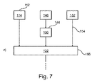
図7に示すさらなる実施例によれば、第2の画像データのために、中で装置が見えている第1の画像サブセット146の複数の画像がレジストレーションサブステップ148において時間に沿って互いにレジストレーションされ、中で装置に関連する領域がブーストされるブースト装置画像データ150を生成する。さらに、第2の画像サブセット152の少なくとも一つの画像が、矢印154で示されるマスク画像データとして供給され、このマスク画像データ154において血管構造が見えている。第1の画像サブセット146と第2の画像サブセット152は血管治療が適用された後の時点に関連する。ステップc)において、第1の画像データ114、ブースト装置画像データ150、及びマスク画像データ154が結合ステップ156において結合されて結合結果可視化画像データ122を生成する。結合ステップ156は図3以下に関して記載される結合ステップ120に従うことが留意される。
According to a further embodiment shown in FIG. 7, for the second image data, a plurality of images of the
結合及び/又はレジストレーションのために、第1の画像サブセット及び第2の画像サブセットにおいて検出可能であるように、例えば見えるようにマーカが設けられ得る。これはさらに図示されない。 For combination and / or registration, a marker may be provided, for example to be visible, so that it can be detected in the first image subset and the second image subset. This is not further illustrated.
装置ブースティングに関して、装置のブースティングの間、装置を囲むバックグラウンドは各画像エリア若しくは領域の経時的な運動のために画像中でぼやけることが留意される。 With respect to device boosting, it is noted that during device boosting, the background surrounding the device is blurred in the image due to the movement of each image area or region over time.
所定医療装置は第2の時点において展開状態で供給されるステントであり得る。言い換えれば、第2の画像データは展開状態における実際に挿入されたステントを示している。 The predetermined medical device may be a stent delivered in a deployed state at a second time. In other words, the second image data shows the actually inserted stent in the deployed state.
ステップc)、すなわち結合ステップにおいて、第1の画像データ114が第2の画像データ118に重ね合わされ、すなわちオーバーレイされ、これは第1の画像データをブースト装置画像データ150及びマスク画像データ154に重ね合わせるすなわちオーバーレイすることにも関連する。
In step c), ie, the combining step, the
ステップc)において、第1の画像データの血管構造は第1のグラフィック方式で示され、第2の画像データの血管構造は第2のグラフィック方式で示され、第1のグラフィック方式は第2のグラフィック方式と異なる(さらに図示しない)。 In step c), the blood vessel structure of the first image data is shown in a first graphic system, the blood vessel structure of the second image data is shown in a second graphic system, and the first graphic system is a second graphic system. Different from graphic system (not shown).
図8に図示の通り、ステップa)において、第1の画像の第1のシーケンス158が供給ステップ160において供給される。ステップb)において、第2の画像の第2のシーケンス162が第2の供給ステップ164において供給される。シーケンスは時間に沿って複数の画像を有する。さらに、第1及び第2のシーケンス158,162はレジストレーションサブステップ166において時間的にレジストレーションされる。
As shown in FIG. 8, in step a), a
さらなる実施例(さらに図示しない)によれば、狭窄が第1の画像、例えば第1の血管造影画像において空間的に検出され、第1の血管造影画像において第1の関心領域を決定する。 According to a further embodiment (not further shown), a stenosis is detected spatially in a first image, for example a first angiographic image, and a first region of interest is determined in the first angiographic image.
第1及び第2の画像若しくは第1及び第2の画像データは同じ心臓フェーズに時間的に同期され得る。 The first and second images or the first and second image data can be synchronized in time to the same cardiac phase.
例えば、第2の関心領域は第1の関心領域に基づいて第2の血管造影画像において決定され得る。 For example, the second region of interest can be determined in the second angiographic image based on the first region of interest.
時間的レジストレーション中、第1及び第2の血管造影画像は時間インデックス(さらに図示しない)を与えられ得る。 During temporal registration, the first and second angiographic images may be given a time index (not shown further).
第1の画像データとして、第1の血管造影画像の第1のシーケンスから第1の血管造影画像が選択され得、第2の画像データとして、第2の血管造影画像の第2のシーケンスから第2の血管造影画像が選択され得る。 A first angiographic image can be selected from the first sequence of the first angiographic image as the first image data, and a second from the second sequence of the second angiographic image as the second image data. Two angiographic images may be selected.
第1及び第2の画像の空間的マッチングのために、運動補正が実行され得る。 Motion correction can be performed for spatial matching of the first and second images.
第1及び第2の画像は同じ呼吸フェーズに空間的に同期され得る。 The first and second images can be spatially synchronized to the same breathing phase.
空間的レジストレーションは各画像データにおいて位置合わせした第1の関心領域と位置合わせした第2の関心領域を提供し得る。 Spatial registration may provide a second region of interest aligned with the first region of interest aligned in each image data.
さらなる実施例によれば、さらに図示しないが、追加時点における血管構造の関心領域の追加画像データが提供される。追加時点は第1の時点と第2の時点の間に配置される。追加画像データもステップc)において結合される。 According to a further embodiment, although not further illustrated, additional image data of a region of interest of the vascular structure at the additional time is provided. The additional time point is arranged between the first time point and the second time point. Additional image data is also combined in step c).
例えば、第2の画像データが追加画像データに重ね合わされ、第1の画像データは追加画像データに重ねられている第2の画像データに重ね合わされる。 For example, the second image data is superimposed on the additional image data, and the first image data is superimposed on the second image data superimposed on the additional image data.
上述若しくは上記の通り、ステップa)及びb)について、複数の第1及び第2の画像が供給され、最適注入画像、最高コントラストなどといった所定パラメータに従って画像若しくは画像データが選択され得る。 As described above or as described above, for steps a) and b), a plurality of first and second images can be supplied and an image or image data can be selected according to predetermined parameters such as optimal injection image, maximum contrast, and the like.
図9は本発明にかかる方法200のさらなる実施形態例を示す。第1の矢印210は血管造影シーケンスの供給を示す。次に、狭窄の空間的検出、若しくは空間位置確認が提供され、これは第1のフレーム212で示される。狭窄の空間位置確認は異なる血管造影シーケンスにおいて決定され得る。例えばこれは、例えば急激に細くなっている血管として注入血管造影画像上で狭窄を明確に検出することによって、若しくは検出が関心狭窄を検出するためにバルーンマーカを頼りにしているステントブースト方策を採ることによって、若しくはユーザによって手動で位置決めすることによってなされ得る。
FIG. 9 shows a further exemplary embodiment of a
ボックス若しくはフレーム212から出る第2の矢印214は狭窄の空間的検出の出力、すなわち関心狭窄領域を示す。
A
矢印のペアは、各ペアが血管治療前、例えばステント留置前の時点と、治療が行われた後、例えばステント留置後の第2の時点に関連することを示していることがさらに留意される。従って、各参照番号の少なくとも一部は治療前の状態若しくは時点に関連するインデックス1を、治療後の時点若しくは状態に関連するインデックス2を追加される。次に、第2の矢印214で示される通り関心狭窄領域を提供することによって、また第3の矢印216で示される通り血管造影シーケンスを提供することによって、血管造影シーケンス検出ステップ218が提供される。例えば、同じ狭窄に関する二つよりも多くの血管造影があり得る。また、一つよりも多くの狭窄が治療され得る。従って一つのステップは異なる狭窄を対応する血管造影(もしあれば)へ割り当てることである。例えばバルーンマーカ方策に従うとき、関心血管造影は例えばマーカの位置がステントブースト中のマーカの位置に近いものである。そして、ステント留置前後の最適血管造影シーケンスが選ばれる必要がある。よい選択は最適注入シーケンス(画像から自動的に決定され得る)を置くことであり得る。勿論、これは血管造影シーケンス検出のボックス218に入る点線矢印220で示される潜在的ユーザインタラクションも有し得る。結果として、若しくは言わば出力として、参照番号222で示される血管造影シーケンス1、すなわちステント留置前、及び参照番号224で示される血管造影シーケンス2、すなわちステント留置後が提供される。さらに、関心狭窄領域1が参照番号226で示され、関心狭窄領域2が参照番号228で示される。四つの矢印222,224,226,228は時間同期ステップ230に入る。
It is further noted that the arrow pairs indicate that each pair is associated with a time point prior to vascular treatment, e.g., prior to stent placement, and a second time point after treatment has been performed, e.g., after stent placement. . Accordingly, at least a portion of each reference number is added with an index 1 associated with the pre-treatment condition or time point and an index 2 associated with the post-treatment time period or condition. Next, an angiographic
時間同期ステップ230の目的はステント留置前後の内腔をオーバーレイすることである。血管が比較可能であるためには、同じ心臓フェーズにおいて観察されなければならない。このステップは二つの考慮される血管造影シーケンス間の時間的対応を発見する。これはECG(さらに図示しない)に基づいて、若しくは画像上で直接(例えば血管を位置合わせすることによって)実行され得る。結果として、時間インデックス対応232が提供される。上述の血管造影シーケンス検出の出力218は即時選択ステップ234にも供給される。
The purpose of the
今までのところ、血管造影シーケンスが依然として考慮されている。ここで最適血管比較を可能にする、同じ心臓フェーズにおける、二つの画像、すなわちステント留置前のものとステント留置後のものを識別する必要がある。これは同じ心臓フェーズの全画像ペアの検査によって、及び最良の一組を選ぶために、例えば可能な限り注入され、他の血管によって閉塞されていない、狭窄視認性に対する基準を結論付けることで可能である。 So far, angiographic sequences are still being considered. It is now necessary to distinguish between the two images in the same cardiac phase that allow optimal blood vessel comparison: pre-stent and post-stent placement. This can be done by examining all image pairs in the same cardiac phase, and in order to select the best set, for example, by injecting as much as possible and concluding a criterion for stenosis visibility that is not occluded by other blood vessels It is.
即時選択ステップ234の出力は第1の血管造影画像2361、及び第2の血管造影画像2362である。これら二つの血管造影画像は空間的血管マッチングステップ238に入る。さらに、空間的血管マッチング238は参照番号226で示される関心狭窄領域1によって、すなわち血管造影シーケンス検出の結果218としても、及び参照番号228で示される関心狭窄領域2によっても入力され、この入力は二つの追加矢印2401及び2402で示される。
The output of the immediate selection step 234 a first
空間的血管マッチングにおいて、臨床医が二つの考慮される検査、すなわちステント留置前後の間でテーブルを動かしたかもしれないこと、及び選択画像が例えば二つの異なる呼吸フェーズにある可能性があることが考慮される。従って、関心血管の部分の完全な位置合わせを実施するために空間的ワーピングが実行されなければならない。これはバルーンマーカを頼りにすることによって可能である。代替的に、一実施例として、運動補正法(ブロックマッチング、デーモンなど)を実行することによって血管をフィルタしてそれらの最適位置合わせを実施することが可能である。両方の方法、すなわちバルーンとそして画像を組み合わせて有益な結果を得ることも可能であり得る。 In spatial vascular matching, the clinician may have moved the table between two considered tests, i.e. before and after stent placement, and the selected image may be in two different breathing phases, for example. Be considered. Therefore, spatial warping must be performed to perform complete alignment of the portion of the vessel of interest. This is possible by relying on balloon markers. Alternatively, as an example, it is possible to filter blood vessels and perform their optimal alignment by performing motion correction methods (block matching, demons, etc.). It may also be possible to obtain beneficial results by combining both methods, i.e. balloons and images.
空間的血管マッチング238の出力として、参照番号2421で示される、すなわちステント留置前の位置合わせした関心領域1、及び参照番号2422で示される、すなわちステント留置後の位置合わせした関心領域2が、オーバーレイ計算ステップ244に供給される。
As an output of the spatial vessel matching 238, there is a registered region of interest 1 indicated by reference numeral 2421, i.e., before the stent placement, and a registered region of interest 2 indicated by
オーバーレイ計算ステップ244において、出力画像が生成される。例えば、両位置合わせ画像は色分けされ得る。血管を増強し及び/又はバックグラウンドを削除し、可能な限り鮮明な出力画像を生成するために何らかの画像処理が実行され得る。オーバーレイ計算244の結果として、最終矢印246が合成概要画像を示す。
In the
例えばステントブースト中に計算されるステント幾何学を最終画像に追加することも可能であり、これはオーバーレイ計算ステップ244に入る第2の点線矢印248で示され、この第2の点線矢印は潜在的ステントブースト結果検討を示す。従って、バルーンマーカがステント留置後最終バルーンマーカ位置と位置合わせされ得る。
For example, it is possible to add the stent geometry calculated during the stent boost to the final image, which is indicated by a second
上記に詳述された異なるステップは明確さのために分離されていることが留意される。アルゴリズム性能は例えば空間的血管マッチング238と即時選択234など、特定ステップを一緒に実行させることから利益を得る。
It is noted that the different steps detailed above are separated for clarity. Algorithmic performance benefits from having certain steps performed together, such as spatial vessel matching 238 and
図10は右側に結合結果可視化画像に対する一実施例300を示す。左列には、原画像がそれぞれ示されており、具体的には、血管治療前の血管構造を示す原画像が上部画像310に示され、血管治療後の同じ血管構造を示す原画像が下部画像320に示される。中央列はバックグラウンドが消去されている考慮される関心狭窄領域を示し、第1の時点における第1の増強画像330が上の行に示され、第2の時点における同様の考慮される関心狭窄領域の第2の画像340が下の行に示される。
FIG. 10 shows an example 300 for the combined result visualized image on the right. The left column, the original image is shown, respectively, specifically, the original image showing the vasculature before vascular therapy is shown in the
右側は上記の通り最終結果を示し、例えば元の血管が第1のグラフィックパターン352で表示され、再開領域が第2のグラフィックパターン354で示される。
The right side shows the final result as described above. For example, the original blood vessel is displayed with the first
図11はX線画像の写真画像と一緒に図10の線画を示す。 FIG. 11 shows the line drawing of FIG. 10 together with a photographic image of the X-ray image.
出力画像、すなわち結合結果可視化画像はインターベンションの二つよりも多くの時間の瞬間も表示し得ることがさらに留意される。複数のステントが同じ領域において展開される場合、手順の進行は異なる色、若しくは異なるグラフィックパターンにおいて、各ステップごとに一つずつ提示され得る。出力は一つの静止画像のみに限定される必要はなく、特に上記の通り画像のシリーズ、各心臓フェーズごとに一つずつが生成され得ることがさらに留意される。それらは各心臓フェーズにおける前後内腔間の差を表示するビデオ(さらに図示しない)に集められ得る。方法のバリエーションは慢性完全閉塞(CTO)治療の進行を説明するために使用され得る。応用は手術の一つよりも多くのステージの色分け提示から利益を受け得る。 It is further noted that the output image, ie the combined result visualization image, can also display more than two moments of time in the intervention. If multiple stents are deployed in the same region, the progress of the procedure can be presented one for each step in different colors or different graphic patterns. It is further noted that the output need not be limited to only one still image, and in particular, as described above, a series of images, one for each cardiac phase, can be generated. They can be collected in a video (further not shown) that displays the difference between the anterior and posterior lumens in each cardiac phase. Variations of the method can be used to account for the progression of chronic total occlusion (CTO) treatment. The application can benefit from the color-coded presentation of more stages than one of the operations.
本発明の別の実施形態例において、適切なシステム上で上記実施形態の一つにかかる方法の方法ステップを実行するように構成されることを特徴とするコンピュータプログラム若しくはコンピュータプログラム要素が提供される。 In another exemplary embodiment of the present invention, there is provided a computer program or computer program element configured to perform the method steps of the method according to one of the above embodiments on a suitable system. .
従ってコンピュータプログラム要素は本発明の一実施形態の一部でもあり得るコンピュータユニット上に記憶され得る。このコンピュータユニットは上記方法のステップを実行する若しくは実行を誘導するように構成され得る。さらに、これは上記装置の構成要素を操作するように構成され得る。コンピュータユニットは自動的に動作するか及び/又はユーザの命令を実行するように構成され得る。コンピュータプログラムはデータプロセッサのワーキングメモリにロードされ得る。従ってデータプロセッサは本発明の方法を実行するように装備され得る。 Thus, the computer program elements can be stored on a computer unit that can also be part of one embodiment of the present invention. The computer unit may be configured to perform or direct the execution of the method steps. Furthermore, it can be configured to operate the components of the device. The computer unit may operate automatically and / or be configured to execute user instructions. The computer program can be loaded into the working memory of the data processor. The data processor can thus be equipped to carry out the method of the invention.
本発明のこの実施形態例は、最初から本発明を使用するコンピュータプログラムと、アップデートによって既存プログラムを本発明を使用するプログラムに変えるコンピュータプログラムの両方をカバーする。 This example embodiment of the present invention covers both computer programs that use the present invention from the beginning and computer programs that change existing programs into programs that use the present invention by updating.
さらに、コンピュータプログラム要素は上記方法の一実施形態例の手順を満たす全所要ステップを提供することができてもよい。 Further, the computer program element may be able to provide all the necessary steps that satisfy the procedure of one example embodiment of the method.
本発明のさらなる実施形態例によれば、CD‐ROMなどのコンピュータ可読媒体が提示され、コンピュータ可読媒体は前節によって記載されるコンピュータプログラム要素をその上に記憶している。 According to a further exemplary embodiment of the present invention, a computer readable medium such as a CD-ROM is presented, on which the computer program element described by the previous section is stored.
コンピュータプログラムは他のハードウェアと一緒に若しくはその一部として供給される光記憶媒体若しくは固体媒体などの適切な媒体上に記憶及び/又は分配され得るが、インターネット又は他の有線若しくは無線通信システムなどを介して他の形式でも分配され得る。 The computer program may be stored and / or distributed on any suitable medium, such as an optical storage medium or solid medium supplied with or as part of other hardware, such as the Internet or other wired or wireless communication system Other formats can also be distributed via
しかしながら、コンピュータプログラムはワールドワイドウェブのようなネットワークを介して提示されてもよいし、ネットワークなどからデータプロセッサのワーキングメモリにダウンロードされることができる。本発明のさらなる実施形態例によれば、コンピュータプログラム要素をダウンロードのために利用可能にするための媒体が提供され、このコンピュータプログラム要素は本発明の前記実施形態の一つにかかる方法を実行するように構成される。 However, the computer program may be presented via a network such as the World Wide Web, or downloaded from the network or the like to the working memory of the data processor. According to a further exemplary embodiment of the present invention, there is provided a medium for making a computer program element available for download, the computer program element performing a method according to one of the above embodiments of the present invention. Configured as follows.
本発明の実施形態は異なる主題を参照して記載されることが留意されるべきである。特に、一部の実施形態は方法タイプクレームに関して記載されるが、他の実施形態は装置タイプクレームに関して記載される。しかしながら、当業者は上記及び下記から、他に通知されない限り、一つのタイプの主題に属する特徴の任意の組み合わせに加えて、異なる主題に関連する特徴間の任意の組み合わせも本願と共に開示されているとみなされることを推測するだろう。しかしながら、全特徴は組み合わされて特徴の単純な総和にとどまらない相乗効果をもたらし得る。 It should be noted that embodiments of the present invention are described with reference to different subject matters. In particular, some embodiments are described with respect to method type claims, while other embodiments are described with respect to device type claims. However, from the above and below, unless otherwise indicated, those skilled in the art will also disclose any combination between features associated with different subject matter in addition to any combination of features belonging to one type of subject matter. You will guess that it is considered. However, all features can be combined to produce a synergistic effect that goes beyond simple summation of features.
本発明は図面と前記説明において詳細に図示され記載されているが、かかる図示と記載は例示若しくは説明であって限定ではないとみなされるものとする。本発明は開示の実施形態に限定されない。開示の実施形態への他の変更は図面、開示及び従属クレームの考察から、請求される発明を実施する上で当業者によって理解されもたらされることができる。 While the invention has been illustrated and described in detail in the drawings and foregoing description, such illustration and description are to be considered illustrative or exemplary and not restrictive. The invention is not limited to the disclosed embodiments. Other modifications to the disclosed embodiments can be understood and effected by those skilled in the art in practicing the claimed invention, from a consideration of the drawings, the disclosure, and the dependent claims.
クレーム中、"有する"という語は他の要素若しくはステップを除外せず、不定冠詞"a"若しくは"an"は複数を除外しない。単一のプロセッサ若しくは他のユニットはクレームに列挙される複数の項目の機能を満たし得る。特定の手段が相互に異なる従属クレームに列挙されるという単なる事実はこれら手段の組み合わせが有利に使用されることができないことを示さない。クレーム中の任意の参照符号は範囲を限定するものと解釈されてはならない。 In the claims, the word “comprising” does not exclude other elements or steps, and the indefinite article “a” or “an” does not exclude a plurality. A single processor or other unit may fulfill the functions of several items recited in the claims. The mere fact that certain measures are recited in mutually different dependent claims does not indicate that a combination of these measured cannot be used to advantage. Any reference signs in the claims should not be construed as limiting the scope.
Claims (15)
処理ユニットと、
インターフェースユニットと、
表示ユニットとを有し、
前記インターフェースユニットが、第1の時点に収集された、血管構造の関心領域の第1の画像データを前記処理ユニットに供給し、第2の時点に収集された、前記血管構造の前記関心領域の少なくとも一つの第2の画像データを前記処理ユニットに供給し、前記第1の時点と前記第2の時点の間に血管治療が前記血管構造に適用され、前記第1の画像データは、前記第1の時点での前記血管構造の前記関心領域を示し、前記第2の画像データは、前記第2の時点での前記血管構造の前記関心領域を示し、
前記第1の時点は治療前状態の時点であり、前記第2の時点は治療後状態の時点であり、治療前状態と治療後状態の間に、前記関心領域内の前記血管構造に作用する医用インターベンションが実行されており、
前記処理ユニットが前記第1の時点の治療前状態の前記血管構造を表す前記第1の画像データと前記第2の時点の治療後状態の前記血管構造を表す前記少なくとも一つの第2の画像データを、前記治療前状態の前記血管構造と前記治療後状態の前記血管構造との空間マッチング及び位置合わせを経て、オーバレイにより結合して結合結果可視化画像データを生成し、
前記表示ユニットが前記結合結果可視化画像データを表示する、
装置。 An apparatus for visualizing the results of vascular treatment,
A processing unit;
An interface unit;
A display unit,
The interface unit supplies first image data of the region of interest of the vasculature collected at the first time point to the processing unit and the region of interest of the vasculature collected at the second time point. At least one second image data is supplied to the processing unit, and vascular treatment is applied to the vascular structure between the first time point and the second time point, and the first image data is The region of interest of the vasculature at a time point 1 and the second image data indicates the region of interest of the vasculature at the second time point;
The first time point is a pre-treatment state time point and the second time point is a post-treatment state time point, acting on the vasculature in the region of interest between the pre-treatment state and the post-treatment state A medical intervention is running,
The first image data representing the vascular structure in the pre-treatment state at the first time point and the at least one second image data representing the vascular structure in the post-treatment state at the second time point by the processing unit. Are subjected to spatial matching and alignment between the vascular structure in the pre-treatment state and the vascular structure in the post-treatment state, and are combined by overlay to generate a combined result visualized image data,
The display unit displays the combined result visualized image data;
apparatus.
前記インターフェースユニットが前記留置された装置の装置画像データを供給し、
前記処理ユニットが前記第1の画像データと前記第2の画像データに加えて前記装置画像データを結合して前記結合結果可視化画像データを生成する、
請求項1又は2に記載の装置。 The vascular treatment comprises placement of a predetermined medical device within the vascular structure;
The interface unit supplies device image data of the indwelling device;
The processing unit combines the device image data in addition to the first image data and the second image data to generate the combined result visualized image data;
The apparatus according to claim 1 or 2.
前記処理ユニットが、前記第1の画像サブセットの複数の画像を時間に沿って互いに位置合わせして結合し、中で前記装置に関連する領域がブーストされるブースト装置画像データを生成し、前記ブースト装置画像データは前記装置画像データとして供給され、
前記処理ユニットが前記第1の画像データ、前記ブースト装置画像データ、及び前記マスク画像データを結合して前記結合結果可視化画像データを生成する、
請求項3乃至5のいずれか一項に記載の装置。 At least one image before the SL interface unit, the device supplies a plurality of images of the first image subset visible second image subset as the mask image data to which the vasculature is visible in in Wherein the first image subset and the second image subset are related to a point in time after the vascular treatment is applied, and the mask image data is provided as the second image data,
The processing unit aligns and combines the plurality of images of the first image subset together in time to generate boost device image data in which regions associated with the device are boosted; Device image data is supplied as the device image data,
The processing unit combines the first image data, the boost device image data, and the mask image data to generate the combined result visualized image data;
Apparatus according to any one of claims 3 to 5.
前記処理ユニットが前記第1のシーケンスと前記第2のシーケンスを時間的に位置合わせする、
請求項1乃至6のいずれか一項に記載の装置。 The interface unit provides a first sequence of first images and a second sequence of second images, the sequence comprising a plurality of images over time;
The processing unit temporally aligns the first sequence and the second sequence;
The apparatus according to claim 1.
前記処理ユニットが前記結合結果可視化画像データの生成のために前記追加画像データも結合する、
請求項1乃至7のいずれか一項に記載の装置。 The interface unit provides additional image data of a region of interest of the vasculature at an additional time point, the additional time point being disposed between the first time point and the second time point;
The processing unit also combines the additional image data to generate the combined result visualized image data;
Apparatus according to any one of claims 1 to 7.
画像収集ユニットと、
請求項1乃至8のいずれか一項に記載の血管治療結果可視化のための装置とを有し、
前記画像収集ユニットが、前記血管構造の関心領域の第1の画像データを供給し、前記血管構造の関心領域の第2の画像データを供給する、
医用イメージングシステム。 A medical imaging system for visualizing vascular treatment results,
An image acquisition unit;
An apparatus for visualizing vascular treatment results according to any one of claims 1 to 8,
The image acquisition unit provides first image data of a region of interest of the vasculature and provides second image data of a region of interest of the vasculature;
Medical imaging system.
a)第1の時点に収集された、血管構造の関心領域の第1の画像データを供給するステップであって、前記第1の画像データは治療前状態の時点である前記第1の時点での前記血管構造の前記関心領域を示す、ステップと、
b)第2の時点に収集された、前記血管構造の前記関心領域の少なくとも一つの第2の画像データを供給するステップであって、前記少なくとも一つの第2の画像データは治療後状態の時点である前記第2の時点での前記血管構造の前記関心領域を示す、ステップと、
c)前記第1の時点の治療前状態の前記血管構造を表す前記第1の画像データと前記第2の時点の治療後状態の前記血管構造を表す前記少なくとも一つの第2の画像データを、前記治療前状態の前記血管構造と前記治療後状態の前記血管構造との空間マッチング及び位置合わせを経て、オーバレイにより結合して結合結果可視化画像データを生成するステップと、
d)前記結合結果可視化画像データを表示するステップとを有し、
前記第1の時点と前記第2の時点の間に前記血管構造へ血管治療が適用されている、
作動方法。 A method of operating a device for visualizing vascular treatment results,
a) supplying first image data of a region of interest of the vasculature collected at a first time point, wherein the first image data is at a time point of a pre-treatment state; Indicating the region of interest of the vascular structure of
b) providing at least one second image data of the region of interest of the vasculature collected at a second time point, wherein the at least one second image data is a post-treatment time point showing the region of interest of the vascular structure at the second time point is a step,
c) the first image data representing the vascular structure in the pre-treatment state at the first time point and the at least one second image data representing the vascular structure in the post-treatment state at the second time point ; A spatial matching and alignment of the vascular structure in the pre-treatment state and the vascular structure in the post-treatment state, combined by overlay to generate a combined result visualized image data;
d) displaying the combined result visualized image data,
Before SL vascular treatment is applied to the vasculature during the second time point and the first point in time,
Actuation method.
前記第1の画像データと前記第2の画像データに加えて、前記結合結果可視化画像データを生成するために前記留置された装置の装置画像データも結合される、請求項10に記載の作動方法。 The vascular treatment comprises placement of a predetermined medical device within the vascular structure;
11. The method according to claim 10, wherein in addition to the first image data and the second image data, device image data of the detained device is also combined to generate the combined result visualized image data. .
中で前記血管構造が見えているマスク画像データとして第2の画像サブセットの少なくとも一つの画像が供給され、前記マスク画像データは前記第2の画像データとして供給され、前記第1の画像サブセットと前記第2の画像サブセットは前記血管治療が適用された後の時点に関連し、
ステップc)において、前記第1の画像データ、前記ブースト装置画像データ、及び前記マスク画像データが結合されて前記結合結果可視化画像データを生成する、
請求項10又は11に記載の作動方法。 Said device being aligned with one another along a plurality of images of the first image subsets have time to visible, associated regions in the device generates a boost device image data to be boosted in a medium, the boost device Image data is supplied as the device image data,
At least one image of a second image subset is provided as mask image data in which the vascular structure is visible, the mask image data is provided as the second image data, and the first image subset and the The second image subset relates to a time point after the vascular treatment has been applied,
In step c), the first image data, the boost device image data, and the mask image data are combined to generate the combined result visualized image data.
12. The operating method according to claim 10 or 11.
前記追加時点が前記第1の時点と前記第2の時点の間に配置され、
前記追加画像データもステップc)において結合される、
請求項10乃至12のいずれか一項に記載の方法。 Additional image data of the region of interest of the vascular structure at the time of addition is provided,
The additional time point is disposed between the first time point and the second time point;
The additional image data is also combined in step c).
The method according to any one of claims 10 to 12.
Applications Claiming Priority (3)
| Application Number | Priority Date | Filing Date | Title |
|---|---|---|---|
| US201161531144P | 2011-09-06 | 2011-09-06 | |
| US61/531,144 | 2011-09-06 | ||
| PCT/IB2012/054294 WO2013035005A1 (en) | 2011-09-06 | 2012-08-24 | Vascular treatment outcome visualization |
Publications (3)
| Publication Number | Publication Date |
|---|---|
| JP2014525308A JP2014525308A (en) | 2014-09-29 |
| JP2014525308A5 JP2014525308A5 (en) | 2015-09-10 |
| JP6482871B2 true JP6482871B2 (en) | 2019-03-13 |
Family
ID=47018312
Family Applications (1)
| Application Number | Title | Priority Date | Filing Date |
|---|---|---|---|
| JP2014527773A Active JP6482871B2 (en) | 2011-09-06 | 2012-08-24 | Visualization of vascular treatment results |
Country Status (7)
| Country | Link |
|---|---|
| US (1) | US11207042B2 (en) |
| EP (1) | EP2744446B1 (en) |
| JP (1) | JP6482871B2 (en) |
| CN (1) | CN103781438B (en) |
| IN (1) | IN2014CN01639A (en) |
| RU (1) | RU2014113387A (en) |
| WO (1) | WO2013035005A1 (en) |
Families Citing this family (10)
| Publication number | Priority date | Publication date | Assignee | Title |
|---|---|---|---|---|
| DE102013211239A1 (en) * | 2013-06-17 | 2014-12-18 | Siemens Aktiengesellschaft | Method of image support and device |
| WO2015044433A1 (en) * | 2013-09-27 | 2015-04-02 | Koninklijke Philips N.V. | Merging vessel maps |
| JP6653667B2 (en) | 2014-05-06 | 2020-02-26 | コーニンクレッカ フィリップス エヌ ヴェKoninklijke Philips N.V. | Devices, systems and methods for vascular evaluation |
| US10603004B2 (en) | 2015-07-27 | 2020-03-31 | Koninklijke Philips N.V. | Revascularisation localisation and pre and post quantitative coronary angiography |
| JP6849665B2 (en) * | 2015-09-10 | 2021-03-24 | コーニンクレッカ フィリップス エヌ ヴェKoninklijke Philips N.V. | Enhanced imaging of vasculature |
| WO2019087674A1 (en) * | 2017-10-31 | 2019-05-09 | 富士フイルム株式会社 | Deviation detection device, method, and program |
| JP6947114B2 (en) * | 2018-04-23 | 2021-10-13 | 株式会社島津製作所 | X-ray imaging system |
| CN112513930A (en) * | 2018-05-29 | 2021-03-16 | 光实验成像公司 | Stent expansion displays, systems and methods |
| JP6554596B2 (en) * | 2018-08-02 | 2019-07-31 | 株式会社Aze | Medical diagnostic support device, method and program |
| JP7165600B2 (en) * | 2019-02-28 | 2022-11-04 | キヤノンメディカルシステムズ株式会社 | X-ray diagnostic equipment and medical information processing equipment |
Family Cites Families (31)
| Publication number | Priority date | Publication date | Assignee | Title |
|---|---|---|---|---|
| EP0463533A1 (en) | 1990-06-29 | 1992-01-02 | Siemens Aktiengesellschaft | Device for aiding a radiologist during percutaneous transluminal coronary angioplasty |
| US5077769A (en) | 1990-06-29 | 1991-12-31 | Siemens Gammasonics, Inc. | Device for aiding a radiologist during percutaneous transluminal coronary angioplasty |
| JPH04364677A (en) * | 1991-06-12 | 1992-12-17 | Toshiba Corp | Picture processing unit for radiographic diagnosis |
| DE19843408C2 (en) * | 1998-09-22 | 2000-10-26 | Siemens Ag | Method for reproducing x-ray images when positioning a catheter inserted into a vessel and device for carrying out the method |
| AU782257B2 (en) * | 1999-09-24 | 2005-07-14 | Stryker European Operations Limited | Method and apparatus for performing intra-operative angiography |
| DE10210647A1 (en) * | 2002-03-11 | 2003-10-02 | Siemens Ag | Method for displaying an image of an instrument inserted into an area of a patient under examination uses a C-arch fitted with a source of X-rays and a ray detector. |
| ATE441360T1 (en) * | 2003-02-25 | 2009-09-15 | Koninkl Philips Electronics Nv | INTRAVASCULAR IMAGING |
| AU2004215898A1 (en) * | 2003-02-26 | 2004-09-10 | Medivas, Llc | Bioactive stents and methods for use thereof |
| US9149322B2 (en) * | 2003-03-31 | 2015-10-06 | Edward Wells Knowlton | Method for treatment of tissue |
| DE10333543A1 (en) * | 2003-07-23 | 2005-02-24 | Siemens Ag | A method for the coupled presentation of intraoperative as well as interactive and iteratively re-registered preoperative images in medical imaging |
| EP4197447A1 (en) * | 2004-08-16 | 2023-06-21 | Corindus, Inc. | Image-guided navigation for catheter-based interventions |
| JP5107720B2 (en) * | 2004-11-24 | 2012-12-26 | コーニンクレッカ フィリップス エレクトロニクス エヌ ヴィ | Multi-feature temporal filtering to improve structure in noisy images |
| US7892177B2 (en) | 2005-02-28 | 2011-02-22 | Scimed Life Systems, Inc. | Systems and methods for estimating the length and position of a stent to be applied within a patient |
| US8700128B2 (en) * | 2005-05-03 | 2014-04-15 | Paieon Inc. | Method and apparatus for positioning a biventrivular pacemaker lead and electrode |
| US7650179B2 (en) | 2005-12-09 | 2010-01-19 | Siemens Aktiengesellschaft | Computerized workflow method for stent planning and stenting procedure |
| US8233962B2 (en) * | 2006-05-16 | 2012-07-31 | Siemens Medical Solutions Usa, Inc. | Rotational stereo roadmapping |
| CN101478917B (en) * | 2006-06-28 | 2012-03-21 | 皇家飞利浦电子股份有限公司 | Spatially varying 2D image processing based on 3D image data |
| US8781193B2 (en) * | 2007-03-08 | 2014-07-15 | Sync-Rx, Ltd. | Automatic quantitative vessel analysis |
| US7941000B2 (en) * | 2007-05-11 | 2011-05-10 | Koninklijke Philips Electronics N.V. | Method for producing an image and system for producing an image |
| US8858609B2 (en) | 2008-02-07 | 2014-10-14 | Intuitive Surgical Operations, Inc. | Stent delivery under direct visualization |
| US20100061611A1 (en) * | 2008-09-11 | 2010-03-11 | Siemens Corporate Research, Inc. | Co-registration of coronary artery computed tomography and fluoroscopic sequence |
| CN102196768B (en) | 2008-10-23 | 2014-01-22 | 皇家飞利浦电子股份有限公司 | Cardiac- and/or respiratory-gated image acquisition system and method for virtual anatomy enriched real-time 2D imaging in interventional radiofrequency ablation or pacemaker placement procedures |
| US20100125282A1 (en) * | 2008-11-14 | 2010-05-20 | Medtronic Vascular, Inc. | Robotically Steered RF Catheter |
| JP4740348B2 (en) | 2009-02-10 | 2011-08-03 | 株式会社東芝 | X-ray diagnostic equipment |
| FR2942124B1 (en) * | 2009-02-17 | 2017-05-12 | Gen Electric | RADIOLOGICAL IMAGING METHOD AND DEVICE |
| US8335552B2 (en) * | 2009-03-20 | 2012-12-18 | Medtronic, Inc. | Method and apparatus for instrument placement |
| CN102365654B (en) * | 2009-03-27 | 2015-05-13 | 皇家飞利浦电子股份有限公司 | Synchronization of two image sequences of a periodically moving object |
| JP5433282B2 (en) | 2009-04-08 | 2014-03-05 | 株式会社東芝 | Image display workstation |
| US8934684B2 (en) * | 2009-07-31 | 2015-01-13 | Siemens Aktiengesellschaft | Method and system for facilitating an image guided medical procedure |
| JP5423222B2 (en) | 2009-08-07 | 2014-02-19 | ソニー株式会社 | Position detection apparatus and position detection method |
| CN102573632B (en) * | 2009-09-29 | 2015-06-17 | 皇家飞利浦电子股份有限公司 | Vascular roadmapping |
-
2012
- 2012-08-24 CN CN201280043285.6A patent/CN103781438B/en active Active
- 2012-08-24 IN IN1639CHN2014 patent/IN2014CN01639A/en unknown
- 2012-08-24 EP EP12772468.0A patent/EP2744446B1/en active Active
- 2012-08-24 US US14/240,853 patent/US11207042B2/en active Active
- 2012-08-24 WO PCT/IB2012/054294 patent/WO2013035005A1/en active Application Filing
- 2012-08-24 JP JP2014527773A patent/JP6482871B2/en active Active
- 2012-08-24 RU RU2014113387/14A patent/RU2014113387A/en not_active Application Discontinuation
Also Published As
| Publication number | Publication date |
|---|---|
| CN103781438A (en) | 2014-05-07 |
| EP2744446B1 (en) | 2021-01-13 |
| CN103781438B (en) | 2017-05-31 |
| RU2014113387A (en) | 2015-10-20 |
| US20140204124A1 (en) | 2014-07-24 |
| JP2014525308A (en) | 2014-09-29 |
| US11207042B2 (en) | 2021-12-28 |
| WO2013035005A1 (en) | 2013-03-14 |
| EP2744446A1 (en) | 2014-06-25 |
| IN2014CN01639A (en) | 2015-05-08 |
Similar Documents
| Publication | Publication Date | Title |
|---|---|---|
| JP6482871B2 (en) | Visualization of vascular treatment results | |
| Tacher et al. | Image guidance for endovascular repair of complex aortic aneurysms: comparison of two-dimensional and three-dimensional angiography and image fusion | |
| JP5965840B2 (en) | Vascular road mapping | |
| US7650179B2 (en) | Computerized workflow method for stent planning and stenting procedure | |
| US10682112B2 (en) | Suppression of independent movements in a series of 2D X-ray fluoroscopy images using a 3D pre-operative volume | |
| JP5795540B2 (en) | Medical image observation system for displaying a region of interest on a medical image | |
| JP6849665B2 (en) | Enhanced imaging of vasculature | |
| Abi-Jaoudeh et al. | Electromagnetic navigation for thoracic aortic stent-graft deployment: a pilot study in swine | |
| CN110891513A (en) | Method and system for assisting in guiding an intravascular device | |
| JP6828083B2 (en) | Automatic motion detection | |
| JP6305915B2 (en) | Medical image device with individual buttons for selecting candidate segmentation images | |
| JP2018525082A (en) | Pre- and post-automatic quantitative coronary angiography | |
| KR101703564B1 (en) | Appratus and method for displaying medical images including information of vascular structure | |
| JP6400694B2 (en) | Select the closest available roadmap | |
| JP6929687B2 (en) | Medical image processing equipment, medical image processing methods, and medical image processing programs | |
| Zhang et al. | Real-time continuous image guidance for endoscopic retrograde cholangiopancreatography based on 3D/2D registration and respiratory compensation |
Legal Events
| Date | Code | Title | Description |
|---|---|---|---|
| A521 | Request for written amendment filed |
Free format text: JAPANESE INTERMEDIATE CODE: A523 Effective date: 20150717 |
|
| A621 | Written request for application examination |
Free format text: JAPANESE INTERMEDIATE CODE: A621 Effective date: 20150717 |
|
| A131 | Notification of reasons for refusal |
Free format text: JAPANESE INTERMEDIATE CODE: A131 Effective date: 20160421 |
|
| A977 | Report on retrieval |
Free format text: JAPANESE INTERMEDIATE CODE: A971007 Effective date: 20160428 |
|
| A601 | Written request for extension of time |
Free format text: JAPANESE INTERMEDIATE CODE: A601 Effective date: 20160720 |
|
| A521 | Request for written amendment filed |
Free format text: JAPANESE INTERMEDIATE CODE: A523 Effective date: 20161021 |
|
| A131 | Notification of reasons for refusal |
Free format text: JAPANESE INTERMEDIATE CODE: A131 Effective date: 20161209 |
|
| RD04 | Notification of resignation of power of attorney |
Free format text: JAPANESE INTERMEDIATE CODE: A7424 Effective date: 20170214 |
|
| A521 | Request for written amendment filed |
Free format text: JAPANESE INTERMEDIATE CODE: A523 Effective date: 20170309 |
|
| A02 | Decision of refusal |
Free format text: JAPANESE INTERMEDIATE CODE: A02 Effective date: 20170622 |
|
| A521 | Request for written amendment filed |
Free format text: JAPANESE INTERMEDIATE CODE: A523 Effective date: 20171020 |
|
| A911 | Transfer to examiner for re-examination before appeal (zenchi) |
Free format text: JAPANESE INTERMEDIATE CODE: A911 Effective date: 20171027 |
|
| A912 | Re-examination (zenchi) completed and case transferred to appeal board |
Free format text: JAPANESE INTERMEDIATE CODE: A912 Effective date: 20171201 |
|
| A601 | Written request for extension of time |
Free format text: JAPANESE INTERMEDIATE CODE: A601 Effective date: 20180913 |
|
| A521 | Request for written amendment filed |
Free format text: JAPANESE INTERMEDIATE CODE: A523 Effective date: 20181221 |
|
| A61 | First payment of annual fees (during grant procedure) |
Free format text: JAPANESE INTERMEDIATE CODE: A61 Effective date: 20190213 |
|
| R150 | Certificate of patent or registration of utility model |
Ref document number: 6482871 Country of ref document: JP Free format text: JAPANESE INTERMEDIATE CODE: R150 |
|
| R250 | Receipt of annual fees |
Free format text: JAPANESE INTERMEDIATE CODE: R250 |
|
| R250 | Receipt of annual fees |
Free format text: JAPANESE INTERMEDIATE CODE: R250 |
|
| R250 | Receipt of annual fees |
Free format text: JAPANESE INTERMEDIATE CODE: R250 |