JP6480404B2 - Method and apparatus for supplying viscous material onto a substrate - Google Patents
Method and apparatus for supplying viscous material onto a substrate Download PDFInfo
- Publication number
- JP6480404B2 JP6480404B2 JP2016500306A JP2016500306A JP6480404B2 JP 6480404 B2 JP6480404 B2 JP 6480404B2 JP 2016500306 A JP2016500306 A JP 2016500306A JP 2016500306 A JP2016500306 A JP 2016500306A JP 6480404 B2 JP6480404 B2 JP 6480404B2
- Authority
- JP
- Japan
- Prior art keywords
- piston
- actuator
- dispenser
- assembly
- housing
- Prior art date
- Legal status (The legal status is an assumption and is not a legal conclusion. Google has not performed a legal analysis and makes no representation as to the accuracy of the status listed.)
- Active
Links
- 239000000758 substrate Substances 0.000 title claims description 30
- 238000000034 method Methods 0.000 title description 35
- 239000011345 viscous material Substances 0.000 title description 23
- 239000000463 material Substances 0.000 claims description 79
- 230000008859 change Effects 0.000 claims description 12
- 230000004044 response Effects 0.000 claims description 6
- 241000239290 Araneae Species 0.000 claims description 3
- 238000000151 deposition Methods 0.000 description 44
- 230000008021 deposition Effects 0.000 description 43
- 238000007689 inspection Methods 0.000 description 8
- 238000000926 separation method Methods 0.000 description 4
- 238000005516 engineering process Methods 0.000 description 3
- 229910000679 solder Inorganic materials 0.000 description 3
- 230000008901 benefit Effects 0.000 description 2
- 238000004140 cleaning Methods 0.000 description 2
- 238000004891 communication Methods 0.000 description 2
- 238000001514 detection method Methods 0.000 description 2
- 230000000694 effects Effects 0.000 description 2
- 239000008393 encapsulating agent Substances 0.000 description 2
- 238000012840 feeding operation Methods 0.000 description 2
- 239000012530 fluid Substances 0.000 description 2
- 239000007788 liquid Substances 0.000 description 2
- 230000007246 mechanism Effects 0.000 description 2
- 230000004048 modification Effects 0.000 description 2
- 238000012986 modification Methods 0.000 description 2
- 238000005381 potential energy Methods 0.000 description 2
- 229910052594 sapphire Inorganic materials 0.000 description 2
- 239000010980 sapphire Substances 0.000 description 2
- 238000007789 sealing Methods 0.000 description 2
- 238000009736 wetting Methods 0.000 description 2
- 230000003044 adaptive effect Effects 0.000 description 1
- 238000007792 addition Methods 0.000 description 1
- 239000000853 adhesive Substances 0.000 description 1
- 230000001070 adhesive effect Effects 0.000 description 1
- 230000000712 assembly Effects 0.000 description 1
- 238000000429 assembly Methods 0.000 description 1
- 238000002485 combustion reaction Methods 0.000 description 1
- 238000010276 construction Methods 0.000 description 1
- 230000008878 coupling Effects 0.000 description 1
- 238000010168 coupling process Methods 0.000 description 1
- 238000005859 coupling reaction Methods 0.000 description 1
- 230000007613 environmental effect Effects 0.000 description 1
- 239000003822 epoxy resin Substances 0.000 description 1
- 230000004907 flux Effects 0.000 description 1
- 239000011346 highly viscous material Substances 0.000 description 1
- 239000004850 liquid epoxy resins (LERs) Substances 0.000 description 1
- 238000004519 manufacturing process Methods 0.000 description 1
- 231100000989 no adverse effect Toxicity 0.000 description 1
- 229920000647 polyepoxide Polymers 0.000 description 1
- 238000003825 pressing Methods 0.000 description 1
- 230000008569 process Effects 0.000 description 1
- 239000003566 sealing material Substances 0.000 description 1
- 239000004065 semiconductor Substances 0.000 description 1
- 238000005476 soldering Methods 0.000 description 1
- 230000007723 transport mechanism Effects 0.000 description 1
Images


Classifications
-
- B—PERFORMING OPERATIONS; TRANSPORTING
- B05—SPRAYING OR ATOMISING IN GENERAL; APPLYING FLUENT MATERIALS TO SURFACES, IN GENERAL
- B05C—APPARATUS FOR APPLYING FLUENT MATERIALS TO SURFACES, IN GENERAL
- B05C5/00—Apparatus in which liquid or other fluent material is projected, poured or allowed to flow on to the surface of the work
- B05C5/02—Apparatus in which liquid or other fluent material is projected, poured or allowed to flow on to the surface of the work the liquid or other fluent material being discharged through an outlet orifice by pressure, e.g. from an outlet device in contact or almost in contact, with the work
- B05C5/0225—Apparatus in which liquid or other fluent material is projected, poured or allowed to flow on to the surface of the work the liquid or other fluent material being discharged through an outlet orifice by pressure, e.g. from an outlet device in contact or almost in contact, with the work characterised by flow controlling means, e.g. valves, located proximate the outlet
-
- B—PERFORMING OPERATIONS; TRANSPORTING
- B05—SPRAYING OR ATOMISING IN GENERAL; APPLYING FLUENT MATERIALS TO SURFACES, IN GENERAL
- B05C—APPARATUS FOR APPLYING FLUENT MATERIALS TO SURFACES, IN GENERAL
- B05C11/00—Component parts, details or accessories not specifically provided for in groups B05C1/00 - B05C9/00
- B05C11/10—Storage, supply or control of liquid or other fluent material; Recovery of excess liquid or other fluent material
- B05C11/1002—Means for controlling supply, i.e. flow or pressure, of liquid or other fluent material to the applying apparatus, e.g. valves
- B05C11/1034—Means for controlling supply, i.e. flow or pressure, of liquid or other fluent material to the applying apparatus, e.g. valves specially designed for conducting intermittent application of small quantities, e.g. drops, of coating material
-
- G—PHYSICS
- G01—MEASURING; TESTING
- G01F—MEASURING VOLUME, VOLUME FLOW, MASS FLOW OR LIQUID LEVEL; METERING BY VOLUME
- G01F11/00—Apparatus requiring external operation adapted at each repeated and identical operation to measure and separate a predetermined volume of fluid or fluent solid material from a supply or container, without regard to weight, and to deliver it
- G01F11/02—Apparatus requiring external operation adapted at each repeated and identical operation to measure and separate a predetermined volume of fluid or fluent solid material from a supply or container, without regard to weight, and to deliver it with measuring chambers which expand or contract during measurement
- G01F11/021—Apparatus requiring external operation adapted at each repeated and identical operation to measure and separate a predetermined volume of fluid or fluent solid material from a supply or container, without regard to weight, and to deliver it with measuring chambers which expand or contract during measurement of the piston type
Landscapes
- Physics & Mathematics (AREA)
- Fluid Mechanics (AREA)
- General Physics & Mathematics (AREA)
- Coating Apparatus (AREA)
- Application Of Or Painting With Fluid Materials (AREA)
- Electric Connection Of Electric Components To Printed Circuits (AREA)
Description
本発明は、包括的には、プリント回路基板等の基材上に粘性材料を供給する方法及び装置に関する。 The present invention relates generally to a method and apparatus for supplying a viscous material onto a substrate such as a printed circuit board.
多様な用途に向けて、計測した量の液体又はペーストを供給するのに用いられる、いくつかのタイプの従来技術の供給システム又はディスペンサーが存在する。そのような用途の1つは、集積回路チップ及び他の電子構成要素を、回路基板(circuit board substrates)上に組み付けることである。本願では、液体エポキシ樹脂、若しくははんだペースト、又は何らかの他の関連材料のドットを回路基板上に供給するのに、自動供給システムが使用される。自動供給システムは、構成要素を回路基板に機械的に固定するアンダーフィル材及び封入材の線を供給するのにも使用される。アンダーフィル材及び封入材は、その組付けの機械的特性及び環境的特性を向上させるように用いられる。 There are several types of prior art dispensing systems or dispensers that are used to dispense a measured amount of liquid or paste for a variety of applications. One such application is assembling integrated circuit chips and other electronic components onto circuit board substrates. In this application, an automated dispensing system is used to dispense dots of liquid epoxy resin, or solder paste, or some other related material onto a circuit board. The automatic supply system is also used to supply lines of underfill and encapsulant that mechanically secure the components to the circuit board. Underfill materials and encapsulants are used to improve the mechanical and environmental properties of the assembly.
別の用途は、回路基板上に、非常に少量、すなわちドットを供給することである。材料のドットを供給することが可能な1つのシステムにおいて、ディスペンサーユニットが、螺旋溝を有する回転オーガを用いて、ノズルから回路基板上に材料を圧出する。そのようなシステムの1つが、本開示の譲受人の子会社であるマサチューセッツ州フランクリン所在のSpeedline Technologies社が所有し、「LIQUID DISPENSING SYSTEM WITH SEALING AUGERING SCREW AND METHOD FOR DISPENSING」という発明の名称の特許文献1に開示されている。 Another application is to provide a very small amount of dots, i.e. dots, on a circuit board. In one system capable of supplying dots of material, a dispenser unit pumps material from a nozzle onto a circuit board using a rotating auger with a spiral groove. One such system is owned by Speedline Technologies, Inc., Franklin, Massachusetts, a subsidiary of the assignee of the present disclosure, and patent document 1 entitled “LIQUID DISPENSING SYSTEM WITH SEALING AUGERING SCREW AND METHOD FOR DISPENSING”. Is disclosed.
オーガ式ディスペンサーを使用する作業において、回路基板上に材料のドット又は線を供給する前に、ディスペンサーユニットを回路基板の表面に向けて下降させ、材料のドット又は線を供給した後、上昇させる。このタイプのディスペンサーを用いて、少ない正確な量の材料を非常に正確に配することができる。ディスペンサーユニットを回路基板に対して垂直方向に下降及び上昇させることは、通常、z軸移動として知られるが、このことに必要な時間は、供給作業を実行するのに必要な時間の一因となる可能性がある。具体的には、オーガ式ディスペンサーの場合、材料のドット又は線を供給する前にディスペンサーユニットを下降させ、それにより、材料が回路基板に接触する、すなわち回路基板を「濡らす」。このように濡らす工程は、供給作業を実行する追加の時間の一因となる。 In an operation using an auger dispenser, the dispenser unit is lowered toward the surface of the circuit board before the material dots or lines are supplied onto the circuit board, and is raised after the material dots or lines are supplied. With this type of dispenser, a small and accurate amount of material can be dispensed very accurately. Lowering and raising the dispenser unit in a direction perpendicular to the circuit board is usually known as z-axis movement, but the time required for this contributes to the time required to perform the supply operation. There is a possibility. Specifically, in the case of an auger-type dispenser, the dispenser unit is lowered before supplying the dots or lines of material so that the material contacts the circuit board, i.e. "wets" the circuit board. This wetting step contributes to the additional time of performing the feeding operation.
また、自動ディスペンサーの分野では、粘性材料のドットを回路基板に向けて発射することが既知である。このようなシステムでは、材料が回路基板に接触する前にノズルから分離することを可能にするのに十分な慣性によって、離散した微量の粘性材料がノズルから噴出される。上述したように、オーガ式応用形態又は他の以前の従来的な供給システムの場合、材料を回路基板に付着させ、それにより、ディスペンサーを引き離すと材料のドットがノズルから分離するように、材料のドットで回路基板を濡らすことが必要である。噴出式の場合、ドットを、離散ドットパターンとして濡らすことなく、基材上に堆積することができるか、又は代替的には、ドットを、融合していくぶん連続的なパターンになるように互いに十分近くに配することができる。このようなシステムの1つの例が、本開示の譲受人であるイリノイ州グレンビュー所在のIllinois Tool Works社が所有する「METHOD AND APPARATUS FOR DISPENSING A VISCOUS MATERIAL ON A SUBSTRATE」という発明の名称の特許文献2に開示されている。 It is also known in the field of automatic dispensers to fire dots of viscous material toward a circuit board. In such a system, discrete, minute amounts of viscous material are ejected from the nozzle with sufficient inertia to allow the material to separate from the nozzle before contacting the circuit board. As mentioned above, in an auger application or other previous conventional delivery system, the material is deposited on the circuit board so that when the dispenser is pulled away, the dots of material separate from the nozzle. It is necessary to wet the circuit board with dots. In the case of the squirt type, the dots can be deposited on the substrate without wetting as a discrete dot pattern, or alternatively the dots are sufficiently close to each other to merge into a somewhat continuous pattern. Can be placed nearby. One example of such a system is a patent document entitled “METHOD AND APPARATUS FOR DISPENSING A VISCOUS MATERIAL ON A SUBSTRATE” owned by Illinois Tool Works, Glenview, Illinois, the assignee of the present disclosure. 2 is disclosed.
本開示の1つの態様は、基材上に材料を供給するように構成されているディスペンサーに関する。1つの実施形態において、該ディスペンサーは供給ユニットを備え、該供給ユニットは、チャンバーを有するハウジングと、該チャンバー内に配置され、該チャンバー内で軸方向に可動なピストンと、前記ハウジングに結合されているノズルとを備える。前記ノズルは、該ハウジングの前記チャンバーと同軸のオリフィスを有する。該ディスペンサーは、前記供給ユニットに結合され、前記ピストンの前記上下運動を駆動するように構成されている、アクチュエーターと、前記アクチュエーター及び前記ピストンに結合されている、コンプライアント組立体とを更に備える。前記コンプライアント組立体は、該アクチュエーターと該ピストンとの制限された相対運動を可能にするように構成されている。 One aspect of the present disclosure relates to a dispenser configured to deliver material onto a substrate. In one embodiment, the dispenser comprises a supply unit, the supply unit being coupled to the housing having a chamber, a piston disposed in the chamber and axially movable in the chamber, and the housing. A nozzle. The nozzle has an orifice coaxial with the chamber of the housing. The dispenser further comprises an actuator coupled to the supply unit and configured to drive the up and down movement of the piston and a compliant assembly coupled to the actuator and the piston. The compliant assembly is configured to allow limited relative movement between the actuator and the piston.
前記ディスペンサーの実施形態は、前記アクチュエーターの位置を検知するセンサーを更に備えてもよい。前記ディスペンサーは、前記ピストンの位置を検知するセンサーを更に備えてもよい。前記ディスペンサーは、前記アクチュエーターを制御するコントローラーを更に備えてもよい。該コントローラーは、フィードフォワード調整ルーチン(feed-forward adaptive routine)を実行するように構成してもよい。該コントローラーは、前記センサーからのセンサーデータと前記フィードフォワード調整ルーチンとを用いて、所望のアクチュエーター運動プロファイルを達成するように前記アクチュエーターの運動を制御するように更に構成してもよい。前記コンプライアント組立体は、該コンプライアント組立体の長さを伸張位置に付勢するように更に構成してもよい。前記コンプライアント組立体は、前記アクチュエーターに結合されているハウジングと、該ハウジングの下端部で該ハウジング内に配置されているプランジャーとを備えてもよく、該プランジャーは、伸張位置に付勢される。前記コンプライアント組立体は、前記ハウジングと前記プランジャーとの間に配置されているばねを更に備えてもよく、該ばねは、前記プランジャーを前記伸張位置に付勢するように構成されている。前記コンプライアント組立体の前記プランジャーは、前記ピストンに下方付勢を加えるように構成してもよく、前記ピストンの下方ストローク中、前記プランジャーは前記ピストンに係合し、前記ばねは前記ハウジング内で圧縮される。1つの実施形態において、前記アクチュエーターは、圧電アクチュエーター組立体としてもよい。別の実施形態において、前記アクチュエーターは、ボイスコイルモーターとしてもよい。1つの実施形態において、前記ピストンは、該ピストンの先端がシートに係合すると停止し、前記コンプライアント組立体は、前記シートに前記ピストンが係合した後で前記アクチュエーターが更に動くことを可能にする。別の実施形態において、前記ピストンは、該ピストンの特徴部が停止部に係合すると停止し、前記コンプライアント組立体は、前記停止部に前記ピストンが係合した後で前記アクチュエーターが更に動くことを可能にする。前記コンプライアント組立体は、コンプライアンス剛性を有してもよく、前記コンプライアント組立体は、前記アクチュエーターと前記ピストンとの相対運動に応じてコンプライアンス剛性を変化させるように構成されている。 The dispenser may further include a sensor that detects a position of the actuator. The dispenser may further include a sensor that detects the position of the piston. The dispenser may further include a controller that controls the actuator. The controller may be configured to execute a feed-forward adaptive routine. The controller may be further configured to control movement of the actuator to achieve a desired actuator movement profile using sensor data from the sensor and the feedforward adjustment routine. The compliant assembly may be further configured to bias the length of the compliant assembly to an extended position. The compliant assembly may include a housing coupled to the actuator and a plunger disposed within the housing at a lower end of the housing, the plunger biased to an extended position. Is done. The compliant assembly may further comprise a spring disposed between the housing and the plunger, the spring being configured to bias the plunger to the extended position. . The plunger of the compliant assembly may be configured to apply a downward bias to the piston, the plunger engaging the piston during a downward stroke of the piston, and the spring being the housing Compressed within. In one embodiment, the actuator may be a piezoelectric actuator assembly. In another embodiment, the actuator may be a voice coil motor. In one embodiment, the piston stops when the tip of the piston engages the seat, and the compliant assembly allows the actuator to move further after the piston engages the seat. To do. In another embodiment, the piston stops when the piston feature engages a stop, and the compliant assembly further moves the actuator after the piston engages the stop. Enable. The compliant assembly may have compliance stiffness, and the compliant assembly is configured to change the compliance stiffness in response to relative movement between the actuator and the piston.
本開示の別の態様は、基材上に材料を供給するようにディスペンサーを動作させる方法に関する。1つの実施形態において、該ディスペンサーは、チャンバーを有するハウジングと、該チャンバー内に配置され、該チャンバー内で軸方向に可動なピストンと、前記ハウジングに結合され、該ハウジングの前記チャンバーと同軸のオリフィスを有するノズルとを備える供給ユニットと、前記供給ユニットに結合され、前記ピストンの前記上下運動を駆動するように構成されている、アクチュエーターとを備える。該方法は、前記アクチュエーターと前記ピストンとの制限された相対運動を可能にすることを含む。 Another aspect of the present disclosure relates to a method of operating a dispenser to deliver material onto a substrate. In one embodiment, the dispenser includes a housing having a chamber, a piston disposed within the chamber and axially movable within the chamber, an orifice coupled to the housing and coaxial with the chamber of the housing. A supply unit comprising a nozzle having an actuator, and an actuator coupled to the supply unit and configured to drive the up and down movement of the piston. The method includes allowing limited relative movement between the actuator and the piston.
前記方法の実施形態は、前記コンプライアント組立体の長さを伸張位置に付勢することを更に含む。前記方法は、前記アクチュエーターと前記ピストンとの相対運動に応じてコンプライアンス剛性を変化させることを更に含んでもよい。前記方法は、前記アクチュエーターの位置を検知すること及び/又は前記ピストンの位置を検知することを更に含んでもよい。前記方法は、フィードフォワード調整ルーチンを行い、前記センサーからのセンサーデータと前記フィードフォワード調整ルーチンとを用いて、所望のアクチュエーター運動プロファイルを達成するように前記アクチュエーターの運動を制御することにより、前記アクチュエーターを制御することを更に含んでもよい。 The method embodiment further comprises biasing the length of the compliant assembly to an extended position. The method may further include changing a compliance stiffness in response to relative movement between the actuator and the piston. The method may further include detecting the position of the actuator and / or detecting the position of the piston. The method performs a feedforward adjustment routine and uses the sensor data from the sensor and the feedforward adjustment routine to control the actuator motion to achieve a desired actuator motion profile. It may further include controlling.
本開示のよりより理解のために図が参照される。図は、参照することにより本明細書の一部をなす。 For a better understanding of the present disclosure, reference is made to the figures. The figures are hereby incorporated by reference.
単に例示のためであり、普遍性を制限するものではないが、ここで、添付の図面を参照しながら本開示が詳細に記述される。本開示は、その応用形態に関して、以下の説明に記載されるか、又は図面に示される構成の細部及び構成要素の配置には限定されない。本開示において記載される原理は、他の実施形態でも使用可能であり、種々の方法において実践又は実行することができる。また、本明細書において用いられる言い回し及び用語は、説明することを目的としており、制限するものと見なされるべきではない。本明細書において「含む(including)」、「備える(comprising)」、「有する(having)」、「含有する(containing)」、「伴う(involving)」及びそれらの変形の用語を使用することは、その対象となるものと、その均等物及び追加のものとを包含することを意味する。 The present disclosure will now be described in detail with reference to the accompanying drawings, which are merely illustrative and not limiting on universality. The disclosure is not limited to the details of construction and the arrangement of components set forth in the following description or illustrated in the drawings in terms of its application. The principles described in this disclosure can be used in other embodiments and can be practiced or carried out in various ways. Also, the wordings and terms used herein are for the purpose of explanation and should not be considered limiting. As used herein, the terms “including”, “comprising”, “having”, “containing”, “involving” and variations thereof are used. , It is meant to encompass its subject and equivalents and additions.
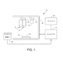
図1は、本開示の1つの実施形態に係る、全体として10で示されているディスペンサーを概略的に示している。ディスペンサー10を用いて粘性材料(例えば、接着剤、封止材、エポキシ樹脂、はんだペースト、アンダーフィル材料等)又は半粘性材料(例えば、はんだ付け用フラックス等)を、プリント回路基板又は半導体ウェハー等の電子基材12の上に供給する。代替的に、ディスペンサー10を、自動車のガスケット材料の塗布用又は或る特定の医療用途等の他の用途に用いることができる。本明細書において用いられるように、粘性材料又は半粘性材料に言及することは例示的であり非限定的であることを意図していることは理解されるべきである。ディスペンサー10は、全体として14で示されている第1の供給ユニット又は供給ヘッド及び、全体として16で示されている第2の供給ユニット又は供給ヘッドと、ディスペンサーの動作を制御するコントローラー18とを備える。2つの供給ユニットが図示されているが、1つ又は複数の供給ユニットを設けることができることは理解されるべきである。
FIG. 1 schematically illustrates a dispenser, indicated generally at 10, according to one embodiment of the present disclosure. Using the
また、ディスペンサー10は、基材12を支持するベース又は支持体22を有するフレーム20と、供給ユニット14、16を支持し動かすようにフレーム20に移動可能に結合された供給ユニットガントリ24と、例えば、校正手順の一部として、粘性材料の供給量を計量し、コントローラー18に重量データを提供する重量測定装置又は重量計26とを備えることができる。ディスペンサー10において、移動ビーム等のコンベヤーシステム(図示せず)又は他の移送機構を用いて、基材をディスペンサーへ装填すること、及びディスペンサーから装填解除することを制御することができる。コントローラー18の制御下において、モーターを用いてガントリ24を移動させ、供給ユニット14、16を基材上の所定の場所に位置決めすることができる。ディスペンサー10は、オペレーターに対して様々な情報を表示する、コントローラー18に接続されたディスプレイユニット28を備えることができる。供給ユニットを制御する任意選択の第2のコントローラーを備えることができる。
The
上記のように、供給動作を実行するのに先立って、基材、例えば、プリント回路基板は、供給システムのディスペンサーに対して位置合わせされるか、又は他の方法で整合されなくてはならない。ディスペンサーはビジョンシステム30を更に備え、ビジョンシステム30は、そのビジョンシステムを支持し動かすようにフレーム20に移動可能に結合されているビジョンシステムガントリ32に結合されている。ビジョンシステムガントリ32は、供給ユニットガントリ24から離されて示しているが、供給ユニット14、16と同じガントリシステムを用いることができる。説明したように、ビジョンシステム30は、基準又は他の特徴及びコンポーネントとして知られている、基材上の目印の場所を検証するのに利用される。位置決めされると、コントローラーは、供給ユニット14、16のうちの一方又は双方の動きを操作して材料を電子基材上に供給するようにプログラムすることができる。
As described above, prior to performing the dispensing operation, the substrate, eg, a printed circuit board, must be aligned or otherwise aligned with the dispenser of the dispensing system. The dispenser further includes a
本開示のシステム及び方法は供給ユニット14、16の構造に関する。本明細書において提供されているシステム及び方法の説明は例示的な電子基材(例えば、プリント回路基板)に言及しており、この電子基材はディスペンサー10の支持体22上に支持されている。1つの実施形態において、供給動作はコントローラー18によって制御され、コントローラー18は、材料ディスペンサーを制御するように構成されるコンピューターシステムを含むことができる。別の実施形態においては、コントローラー18はオペレーターによって操作することができる。
The systems and methods of the present disclosure relate to the structure of the
図2を参照すると、全体として200で示されている例示的な材料堆積システムを、マサチューセッツ州フランクリン所在のSpeedline Technologies社が提供するXYFLEXPRO(商標)ディスペンサープラットフォームによって構成してもよい。1つの実施形態において、材料堆積システム200は、材料堆積システムの構成部品を支持するフレーム202を備える。構成部品としては、限定はしないが、材料堆積システムのキャビネット内に位置付けられるコントローラー18等のコントローラーが挙げられる。図示のように、材料堆積システム200は、それぞれ全体として204、206で示され、低粘性材料(例えば、50センチポアズ未満)、半粘性材料(例えば、50センチポアズ〜100センチポアズ)、粘性材料(例えば、100センチポアズ〜1000センチポアズ)、及び/又は高粘性材料(例えば、1000センチポアズよりも高い)を堆積する2つの堆積ユニット、すなわち供給ヘッドを更に有する。堆積ユニット204、206は、コントローラー18の制御下で、全体として208で示されているガントリシステムによって直交軸に沿って可動としてもよく、それにより、上述したように場合によっては電子基材又は回路基板と称される場合がある基材12等の回路基板上に、材料を供給することが可能になる。カバー(図示せず)を設けることができるが、堆積ユニット204、206及びガントリシステム208を含む、材料堆積システム200の内部構成部品を見えるようにするためにカバーは示されていない。2つの堆積ユニット204、206が図示され説明されているが、任意の数の堆積ユニットを設けることができ、本開示の範囲内に含めることができる。
Referring to FIG. 2, an exemplary material deposition system, indicated generally at 200, may be constructed with the XYFLEXPRO ™ dispenser platform provided by Speedline Technologies, Inc., Franklin, Massachusetts. In one embodiment, the
材料堆積システム200に送られる、基材12等の回路基板は、通常、或るパターンのパッド、又は材料が堆積される他の表面域を有する。材料堆積システム200は、材料堆積システムの各側に沿って設けられている開口212を通してアクセス可能であり、回路基板をx軸方向に、材料堆積システム内の堆積位置まで移送するコンベヤーシステム210も備える。コンベヤーシステム210は、材料堆積システム200のコントローラーによって指示を受けて、堆積ユニット204、206の下の供給場所へ回路基板を供給する。回路基板は堆積ユニット204、206の下の位置に到達すると、製造作業、例えば堆積作業のための所定の位置に置かれる。
A circuit board, such as the
材料堆積システム200は、図1に示すビジョンシステム30等のビジョン検査システムを更に備え、このビジョン検査システムは、回路基板を位置合わせし、回路基板上に堆積される材料を検査するように構成される。1つの実施形態において、ビジョン検査システムは堆積ユニット204、206の一方、又はガントリシステム208に固定される。回路基板上に材料を首尾よく堆積させるように、回路基板と堆積ユニット204、206とがコントローラー18によって位置合わせされる。ビジョン検査システムからの読取り値に基づき、堆積ユニット204、206及び/又は回路基板を移動させることにより、位置合わせが達成される。堆積ユニット204、206と回路基板とが正しく位置合わせされると、堆積ユニットは堆積作業を実行するように操作される。堆積作業の後、ビジョン検査システムによって回路基板の任意選択の検査を行って、適量の材料が堆積されていることと、その材料が回路基板上の適切な場所に堆積されていることとを保証することができる。ビジョン検査システムは、回路基板上の、基準、チップ、基板穴、チップ縁、又は他の認識可能なパターンを使用して、適切な位置合わせを確定することができる。回路基板の検査後、コントローラーは、コンベヤーシステムを使用した次の場所への回路基板の移動を制御し、上記次の場所において、基板組立てプロセスにおける次の作業を実行することができる。例えば、回路基板上に電気部品を配置してもよいし、基板上に堆積されている材料を硬化させてもよい。
The
いくつかの実施形態において、材料堆積システム200は以下のように動作することができる。回路基板は、コンベヤーシステムを用いて、材料堆積システム200内の堆積位置に装填することができる。回路基板は、ビジョン検査システムを用いることにより、堆積ユニット204、206と位置合わせされる。次に、堆積ユニット204、206は、コントローラー18によって始動されて堆積作業を行うことができる。この堆積作業において、材料が回路基板上の正確な位置に堆積される。堆積ユニット204、206が堆積作業を実行すると、回路基板はコンベヤーシステムによって材料堆積システム200から移送してもよく、それにより、第2の後続の回路基板を材料堆積システム内に装填することができる。堆積ユニット204、206は、速やかに取り外して他のユニットと交換されるように構成することができる。
In some embodiments, the
図3を参照すると、本開示の一実施形態の供給ユニット(全体として300で示す)が示されている。この供給ユニットを以下に記載する。図示のように、供給ユニット300は、ハウジング302と、ハウジングに脱離可能に取り付けられているノズル組立体(全体として304で示す)とを備える。具体的には、ディスペンサーハウジング302は、軸Aに沿ってアクチュエーターに結合されており、細長いチャンバー306を画定するように構成されている。細長いチャンバー306は、供給される粘性材料を受け取るように設計されている。シールナット308及び好適なシール310が、ピストンガイドすなわちチャンバー構造部312の上部をハウジング302のチャンバー306内に固定する。ピストンガイド312の下部は、ノズル組立体304によって固定される。ノズル組立体304は、ノズルナット314と、ピストンガイド312の下部が当接するバルブシート316とを備える。円筒形チャンバー306は、材料供給管318と流体連通する供給キャビティを画定する。材料供給管318は、材料供給組立体から材料を受け取るようになっている。図示のように、材料供給管318は、粘性材料を、ピストンガイド312の上部において入口320を通してチャンバー306内に導入する。以下でより詳細にするが、粘性材料は、圧力下でチャンバー306の小供給キャビティに送出される。供給ユニット300は、部分的にシールナット308及びピストンガイド312内に配置されている往復ピストン322を更に備える。ピストン322は、ヨークを介し(by)ばね及びプランジャーによって下方に付勢される(これはアクチュエーターが駆動する)上端部と、バルブシート316に係合するように構成されている下端部とを有する。ピストン322は、チャンバー306内に収まり、チャンバー306内で軸Aに沿って摺動するように構成されている。
Referring to FIG. 3, a supply unit (generally indicated at 300) of one embodiment of the present disclosure is shown. This supply unit is described below. As shown, the
図4を参照すると、供給ユニット300の下部が示されている。図示のように、ノズルナット314は、ハウジング302の下部に螺着されており、バルブシート316をノズルナットとピストンガイド312の下端部との間に固定するように構成されている。バルブシート316は、円錐面400と、例えば直径0.005インチの小径ボア402とが形成されている、略円筒形の部材を備える。1つの実施形態において、バルブシート316は、合成サファイア等の硬質の材料で作製してもよい。この構成では、ピストン322がバルブシート316に係合すると、小径ボア402から基材上に、例えば回路基板12上に粘性材料が噴射されるようになっている。特定の一実施形態において、ノズル組立体304は、ノズル組立体の清掃を助けるように、完全な組立体としてディスペンサー300のエンドユーザーに提供してもよい。具体的には、ニードルナット314を外すことにより、使用したノズル組立体304を供給ユニット300のハウジング302から完全に取り外し、新しい(きれいな)ノズル組立体と交換することができる。
Referring to FIG. 4, the lower part of the
動作時、往復ピストン322は、ハウジング302のチャンバー306内に設けられているピストンガイド312内において、上位置と下位置との間で可動である。供給媒体、例えばはんだペーストは、圧力下で入口320を通ってチャンバー306に導入され、供給材料は、ピストンガイド312に形成されているスリット404を通して、バルブシート316上方の開放空間に流れる。下位置では、ピストン322はバルブシート316に着座し、上位置では、ピストンはノズル組立体のバルブシートから上昇している。以下に記載するように、アクチュエーター組立体は、ピストン322に結合されている圧電アクチュエーター又はボイスコイルモーターのうちの一方を備え、(フレクシャ組立体を介した)アクチュエーター組立体の動作が、上位置と下位置との間でのピストンの運動を引き起こす。ピストン322がバルブシート316に当接するその下降位置に動く場合、材料の小滴が、バルブシートに形成されている小径ボア402を通して供給される。
In operation, the
論じたように、供給ユニット300は、供給材料源に加圧空気を提供し、材料供給管318を介して、材料を供給ユニットのハウジングに導入する。与える特定の圧力は、使用される材料と、供給される材料量と、供給ユニット300の動作モードとに基づき選択することができる。ディスペンサーの動作中、ユーザーが、供給プラットフォーム用ユーザーインターフェースを介して回路基板上の供給エリアを定義する。供給ユニット300を用いて、材料のドット及び線を供給することができる。供給ユニット300が、ディスペンサーの複数回の供給サイクルによって形成される材料の線を供給するのに用いられ、また、個々の供給サイクルを用いて回路基板又は他の基材上の選択した場所に材料を供給するのに用いられる場合。材料の線の場合、ユーザーは、線の開始位置と終了位置とを定義する。供給プラットフォームは、供給ユニット300を移動させて線に沿って材料を配することが可能である。供給ユニット制御パネルを使用して、回路基板上の全ての供給エリアを定義するとともに供給パラメーターを設定すると、ディスペンサーは、処理される回路基板を受け取ることが可能である。回路基板を供給場所に移動させた後、ディスペンサーは、供給ユニットを供給場所上方に位置決めするようにガントリシステム208を制御する。別の実施形態において、回路基板を固定供給ユニットの下に移動させてもよい。個々の基板について、材料がその基板の全ての場所に供給されるまで供給を続ける。次に、その基板をシステムから取り出し、新しい基板をシステムに装填することができる。
As discussed,
図5を参照すると、本開示の別の実施形態の供給ユニット(全体として500で示す)が示されている。この供給ユニットを以下に記載する。図示のように、供給ユニット500は、ハウジング502と、ハウジングに脱離可能に固定されているノズル組立体(全体として504で示す)とを備える。具体的には、軸Bに沿ってアクチュエーターに結合されているディスペンサーハウジング502は、供給される粘性材料を受け取るように構成された細長いチャンバー506を画定するように構成されている。シールナット508及び好適なシール510は、ピストンガイド512の上部をハウジング502のチャンバー506内に固定する。ピストンガイド512の下部は、ノズル組立体504によって固定される。ノズル組立体504は、ノズルナット514と、ノズルナットによって保持されるように構成されているノズル516とを備える。チャンバー506は、材料供給管518と流体連通する小供給キャビティを画定する。材料供給管518は、材料供給組立体から材料を受け取るようになっている。図示のように、材料供給管518は、粘性材料を、ピストンガイド512の上部において入口520を通してチャンバー506内に導入する。以下でより詳細に記載するが、粘性材料は、圧力下でチャンバー506に送出される。供給ユニット500は、シールナット508及びピストンガイド512内に配置されているピストン522を更に備える。ピストン522は、フレクシャ組立体を介してアクチュエーターに固定されている上端部と、ピストンガイド512の下部に形成されている小オリフィス524に出入りするように構成されている下端部とを有する。ピストン522は、円筒形チャンバー内に収まり、円筒形チャンバー内で軸Bに沿って摺動するように構成されている。シールナット508に形成されている凹部内に、停止部526が設けられている。停止部526は、コンプライアント材料で形成することができる。停止部526は、ピストン522の頭部に係合して、供給動作時のピストン522の下方移動を停止する。
Referring to FIG. 5, another embodiment of a supply unit of the present disclosure (shown generally at 500) is shown. This supply unit is described below. As shown, the
図6を参照すると、供給ユニット500の下部が示されている。図示のように、ピストン522の下端部は、小オリフィス524を通って移動し、それによりノズル516上方の位置に至るように構成されている。ノズル516は、円錐面600と、例えば直径0.005インチの小径ボア602とが形成されている、略円筒形の部材を備える。1つの実施形態において、ノズル516は、合成サファイア等の硬質の材料で作製してもよい。この構成では、ピストン522が、ノズル516上方かつピストンガイド512の端部の下方の空間内に供給された材料を移動させると、小径ボア602から基材上に、例えば回路基板12上に粘性材料が噴射されるようになっている。特定の一実施形態において、ノズル組立体504は、ノズル組立体の清掃を助けるように、完全な組立体としてディスペンサーのエンドユーザーに提供してもよい。具体的には、ニードルナットを外すことにより、使用したノズル組立体を供給ユニット500から完全に取り外し、新しい(きれいな)ノズル組立体と交換することができる。
Referring to FIG. 6, the lower part of the
図7を参照すると、供給ユニット、例えば供給ユニット300とともに、任意選択のノズルヒーター組立体(全体として700で示す)を用いてもよい。コントローラー18に接続されているユーザーインターフェースを用いて、ノズルヒーター組立体の温度を設定することができる。任意選択のノズルヒーター組立体700は、本開示の範囲内で供給ユニット500に用いることができることに留意すべきである。ノズルヒーター組立体700は、ヒーターを設定温度に維持するようにシステムによって制御される。ノズルヒーター組立体700は、供給ユニットのハウジング302の下部に、例えば図7に示すようなノズルナット314に取り付けられて、バルブシート316上方の材料に熱を与えるように構成されている。1つの実施形態において、ノズルヒーター組立体700は、本体702を備える。本体702は、カートリッジヒーターと、温度センサーと、取付金具とを備える。本体702は、供給ユニット300の下部すなわちノズル組立体304が貫通する、下側開口を有する。本体702のハウジングをノズル組立体304のノズルナット314に押し付けることによってノズルヒーター組立体700を供給ユニット300に固定するように、クランプを設けてもよい。カートリッジヒーター及び温度センサーを、システムコントローラーに接続してもよい。システムコントローラーは、温度センサー近位の温度を設定値に維持する。
Referring to FIG. 7, an optional nozzle heater assembly (generally indicated at 700) may be used with a supply unit, eg,
図8Aを参照すると、1つの実施形態において、ピストン322の上端部は、場合によってはコンプライアント組立体と称するコンプライアントフレクシャ組立体(全体として800で示す)に固定されている。コンプライアントフレクシャ組立体は、ピストンをアクチュエーター組立体に固定し、ピストンの軸方向往復運動をもたらすように構成されている。図示のように、ピストン322の上端部は、頭部802を含む。コンプライアントフレクシャ組立体800は、略円筒形のフレクシャハウジング804を備える。フレクシャハウジング804は、ねじ806によって圧電アクチュエーター組立体のレバーアームに固定してもよい。別の実施形態において、コンプライアントフレクシャ組立体800は、ボイスコイルモーターアクチュエーター組立体に固定してもよい。フレクシャハウジング804は、減肉部すなわちフレクシャ要素808を有する。フレクシャ要素808は、圧電アクチュエーター組立体のレバーアームがフレクシャ組立体及びピストン322の相対運動を駆動する際に、フレクシャ組立体800が圧電アクチュエーター組立体のレバーアームの円弧運動に対応することを可能にする。
Referring to FIG. 8A, in one embodiment, the upper end of
フレクシャ組立体800は、フレクシャハウジング804内に配置されているばねハウジング810と、ばねハウジングの下端部でばねハウジング内に配置され、ばねハウジング内で軸方向に可動なプランジャー812と、ばねハウジングとプランジャーとの間に配置されているばね814とを更に備える。プランジャー812は、ピストン322の頭部802を捕捉するように構成されているヨークフィンガー816を備える。コンプライアントフレクシャ組立体800は、フレクシャハウジング804及びばねハウジング810内に配置されているロッド818を更に備える。ロッドは、プランジャー812に固定されている下端部を有する。この構成では、フレクシャ組立体800のプランジャー812がピストン322の頭部802に下方付勢を加えるようになっている。
The
具体的には、供給ユニット300の動作中、アクチュエーター組立体は、フレクシャ組立体800及びピストン322の上下運動を駆動する。ピストン322がバルブシート316に係合する下方ストローク中、アクチュエーター組立体及びフレクシャ組立体800は、ピストンが移動を突然停止しても、下方への駆動を続行する傾向がある。この動作中、フレクシャハウジング804がその下方への移動を続けると、プランジャー812はピストン322の頭部802に係合し、ばね814はばねハウジング810内で圧縮される。ピストン322がバルブシート316内のシール位置にある場合、ばね814は、プランジャー812を下方に付勢して、ピストンをバルブシート内にしっかりと着座させ、それにより、供給ユニット300を閉鎖するように構成されている。
Specifically, during operation of the
フレクシャ組立体800は、フレクシャハウジングの下端部でフレクシャハウジング804の回りに配置されている第2のフレクシャ要素820を更に備えてもよい。1つの実施形態において、第2のフレクシャ要素820は、2つの運動自由度、例えば垂直及びピッチを可能にするスパイダーフレクシャで具現してもよい。スパイダーフレクシャは、圧電アクチュエーター組立体のレバーアームがピストン322の上下運動を駆動する際、圧電アクチュエーター組立体のレバーアームの円弧運動に対応するのに更に役立つ。
The
図8Bを参照すると、別の実施形態において、ピストン522の上端部は、場合によってはコンプライアント組立体と称するコンプライアントフレクシャ組立体(全体として850で示す)に固定されている。コンプライアントフレクシャ組立体は、ピストンを圧電アクチュエーター組立体等のアクチュエーター組立体に固定し、ピストンの軸方向往復運動をもたらすように構成されている。フレクシャ組立体800と同様に、フレクシャ組立体850は、ボイスコイルモーターアクチュエーター組立体に固定してもよい。図示のように、ピストン522の上端部は、2つの離間した頭部852、854を有する。フレクシャ組立体850は、ピストンの2つの頭部852、854間の空間内でピストン522の上側頭部852を固定するように構成されているヨーク856を備える。フレクシャ組立体850は、アクチュエーター組立体によって操作される略円筒形のフレクシャハウジング858を更に備える。圧電アクチュエーター組立体の場合、フレクシャハウジング858は、減肉部すなわちフレクシャ要素(図8Bには図示せず)を備えてもよい。このフレクシャ要素は、レバーアームがフレクシャ組立体及びピストン522の相対運動を駆動する際に、フレクシャ組立体850がレバーアームの円弧運動に対応するのを可能にする。
Referring to FIG. 8B, in another embodiment, the upper end of
フレクシャ組立体850は、フレクシャハウジング858内に配置されているばねハウジング860と、ばねハウジングの下端部でばねハウジング内に配置され、ばねハウジング内で軸方向に可動なプランジャー862と、ばねハウジングとプランジャーとの間に配置されているばね864とを更に備える。この構成では、上述したように、ロッド866の下端部がプランジャー862に固定され、ばねハウジング858内でのピストン522の軸方向運動をもたらすようになっている。停止部526を、ピストンの下側頭部854に係合することによってピストン522の移動を停止するように設けてもよい。この構成では、フレクシャ組立体850のプランジャー862がピストン522の頭部852に下方付勢を加えるようになっている。具体的には、供給ユニット500の動作中、アクチュエーター組立体は、フレクシャ組立体850及びピストン522の上下運動を駆動する。ピストン522の頭部854が停止部526に係合する下方ストローク中、アクチュエーター組立体及びフレクシャ組立体850は、ピストンが移動を突然停止しても、下方への駆動を続行する傾向がある。この動作中、フレクシャハウジング858がその下方への移動を続けると、プランジャー862はピストン522の頭部852に係合し、ばね864はばねハウジング860内で圧縮される。
The
図9は、本開示の実施形態の供給ユニット300、500を動作させる圧電アクチュエーター組立体(全体として900で示す)を示している。図示のように、圧電アクチュエーター組立体900は、供給ユニット300、500を圧電アクチュエーター組立体900に固定するように構成されているハウジング902を備える。圧電アクチュエーター組立体900のハウジング902は、供給動作時に供給ユニットを移動させるために、ガントリ208に好適に固定されている。
FIG. 9 illustrates a piezoelectric actuator assembly (generally designated 900) that operates the
図10、11を参照すると、供給ユニット300とともに圧電アクチュエーター組立体900が示されている。圧電アクチュエーター組立体900は、本開示の範囲で供給ユニット500とともに用いることができることが理解されるべきである。圧電アクチュエーター組立体900のハウジング902は、圧電アクチュエーター組立体の構成部品を支持するように構成されている。図示のように、圧電アクチュエーター組立体は、ピストン322の素早い上下運動を行わせるように、フレクシャ組立体800に固定されている。具体的には、圧電アクチュエーター組立体900はレバーアーム1100を備え、レバーアーム1100は、フレクシャ組立体800のフレクシャハウジング804の上端部に固定されるように構成されている端部1102を有する。圧電組立体は、圧電スタックインターフェースブロック1104と、取付けブロック1106と、レバーアーム1100、インターフェースブロック1104、及び取付けブロックの間に配置されているヒンジ1107とを更に備える。ヒンジ1107は、レバーアーム1100がインターフェースブロック1104の上下運動に関して揺動又は枢動するのを可能にする、2つの枢動点1108、1110を有する。インターフェースブロック1104は、インターフェースブロック上方に位置決めされている圧電スタック1112によって上下方向に動く。その結果、1つの実施形態において、圧電スタック1112は、インターフェースブロックを65ミクロン(0.065ミリメートル)の距離だけ動かすことが可能である。インターフェースブロック1104のこの動きは、レバーアーム1100を介して、650ミクロン(0.65ミリメートル)のフレクシャ組立体の軸方向運動を引き起こす。圧電スタックは、最大1000ヘルツの速度で動作することができる。フレクシャ組立体800は、ピストン322が上下往復運動する際に、ピストンの望ましくない横方向の動きに対処するように構成されている。そのため、圧電アクチュエーター組立体900は、圧電スタック1112の運動を変換して、フレクシャ組立体800の上下運動を引き起こし、さらに、ピストン322の上下運動を引き起こすことが可能である。
Referring to FIGS. 10 and 11, a
圧電アクチュエーター組立体900は、圧電アクチュエーター組立体の運動の閉ループ検出を提供するセンサー組立体(全体として1114で示す)を更に備える。具体的には、センサー組立体l114は、レバーアーム1100の運動を判定するために、レバーアーム1100上に設けられたターゲットを検出するように構成されているレバーアームセンサー1116と、ロッド818の運動を判定するために、ロッドの上端部に設けられたターゲットを検出するように構成されているロッドセンサー1118とを含む。レバーアームセンサー1116は、ハウジング902に固定され、レバーアーム1100上に設けられたターゲットから所定の距離のところに位置決めされる。この所定の距離すなわち隔たりは、動作中のレバーアーム1100の運動量を判定するためにレバーアームセンサー1116によって検出される。同様に、ロッドセンサー1118は、ハウジング902に固定され、ロッド818上のターゲットから所定の距離のところに位置決めされる。この所定の距離すなわち隔たりは、動作中のロッド818の運動量を判定するためにロッドセンサー1118によって検出される。ロッドセンサー1118の場合、ロッド818の上端部には、ロッドセンサーが検出する物体を提供するセンサーターゲット1120がある。
センサー組立体1114は、ピストンの往復運動のフィードフォワード制御を提供する制御システムの一部として用いることができる。粘度等の動作パラメーターが変化しても所望の運動プロファイルが達成されるのを確実にするように、アクチュエーター組立体の駆動に用いられる駆動信号を変化させることができる調整ルーチンを設けてもよい。例えば、材料の粘度は、時間及び温度に比例して変化する可能性がある。この粘度変化に起因して、アクチュエーター組立体にかかる荷重が変化し、したがって、達成される実際の運動が変わる可能性がある。運動プロファイルにおけるこの変化を検知することにより、後続の駆動信号を、所望の運動プロファイルを維持するように適宜調整することができる。これらの動作パラメーター変化は、時間及び温度に比例して緩やかに変化する(drift slowly)傾向があるので、フィードフォワード調整ルーチンは、これらの変化をリアルタイムに追跡することができる。これは、駆動信号をシステムの全帯域幅でリアルタイムに変化させるフィードバック制御システムとは全く異なる。フィードフォワード制御システムでの調整に必要とされるのは、補償を意図される変化よりも速い速度で調整することだけである。フィードフォワード制御システムの圧倒的な利点は、フィードバック制御システムとは異なり、無条件で安定であるように設計することができることである。
The
ロッド818の上端部は、2つのボールプランジャー1122、1124と、ボールプランジャーに結合されている解放レバー1126とを備えるプランジャー組立体に更に結合されている。2つのボールプランジャー1122、1124は、通常動作中、解放レバー1126を退けるように(下方に)付勢する。解放レバー1126が退いた状態では、供給ユニットは、動作範囲の制限なく自由に動作することができる。供給ユニットが解放されると、圧電スタック1112の電力が落ち、レバーアーム1100は知られた場所に動く。ピストンを解放するには、フレクシャ組立体800のコンプライアンスばね814を圧縮して、ピストン322の頭部802を解放する。これは、解放レバー1126を上昇させることにより達成され、解放レバー1126は、ボールプランジャー1122、1124を押圧する。解放レバー1126には、2つの組のねじ(明示せず)が設けられている。これらの2つの組のねじがターゲットの底部上で上昇する。さらに、ターゲットがロッド818上で上昇し、ロッド818がプランジャー812上で上昇し、最終的に、プランジャー812がばね814を圧縮してピストン322を解放する。
The upper end of
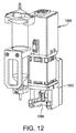
別の実施形態において、供給ユニット、例えば供給ユニット300又は500を動作させるように、ボイスコイルモーターアクチュエーター組立体を設けてもよい。ボイスコイルモーターアクチュエーター組立体は、当該技術分野でよく知られており、ピストン322又は522の動作を駆動するように、供給ユニットに好適に結合することができる。例えば、図12は、供給ユニット、例えば供給ユニット300又は500を動作させるボイスコイルモーターアクチュエーター組立体(全体として1200で示す)を示している。図示のように、ボイスコイルモーターアクチュエーター組立体1200は、場所1204において供給ユニットをボイスコイルモーターアクチュエーター組立体1200に固定するように構成されているハウジング1202を備える。ボイスコイルモーターアクチュエーター組立体1200のハウジング1202は、供給動作時に供給ユニットを移動させるために、ガントリ208に好適に固定されている。1つの実施形態において、ボイスコイルモーターアクチュエーター組立体は、3つの2極3コイル磁石モーターを備えてもよい。
In another embodiment, a voice coil motor actuator assembly may be provided to operate a supply unit, such as
動作時、供給ユニット300又は500は、基材、例えば回路基板12を超える公称クリアランス高さに位置決めされる。このクリアランス高さは、供給動作の間、回路基板上方の比較的一定の高さに維持される。ただし、回路基板の高さ変化又は回路基板頂面の平坦度のばらつきが、クリアランス高さを変化させる可能性がある。この場合、粘性材料の供給に悪影響はない。具体的には、ディスペンサーユニットは、各供給動作の最後に、z軸方向において回路基板から離れるようにノズルを上昇させる必要がない。一方で、回路基板の高さ変化及び回路基板の平坦度のばらつきに適応するために(又は更には障害を回避するために)、ディスペンサーは、z軸運動を達成するように構成してもよい。いくつかの実施形態において、レーザー検出システムを用いて、ディスペンサーの高さを判定してもよい。
In operation,
このように、本開示の特徴は、コンプライアントフレクシャ組立体800の軸方向コンプライアンスであることが認識されるべきである。このコンプライアンスは、ピストン322がバルブシート316に接触した場合、又はピストン522の下側頭部854が停止部526に接触した場合、ピストン322が突然停止することを可能にすると同時に、フレクシャ組立体800がこの接触点を超えて更に動くことを可能にする。コンプライアントフレクシャ組立体800は、(フレクシャハウジング804を介する)アクチュエーター組立体とピストン322又は522との制限された相対運動を可能にする。この運動の分離は、アクチュエーター組立体に対する衝撃荷重を減少させるとともに、ピストンの減速度を増大させる。また、いくつかの動作モードにおいては、この運動の分離は、フレクシャ組立体の運動エネルギーを、圧縮したコンプライアンスばねの位置エネルギーに変換することと、続いて、ばねがアクチュエーターを逆方向に加速させるように働くことにより、この位置エネルギーをアクチュエーターの運動エネルギーとして回収することとによって、よりエネルギー効率的な動作を可能にする。図示及び記載したように、コンプライアントフレクシャ組立体800は、組立体、すなわちプランジャー812又は862の長さを伸張位置に伸ばすように更に構成されている。コンプライアントフレクシャ組立体800は、コンプライアンス剛性を有する。コンプライアントフレクシャ組立体800は、アクチュエーターとピストンとの相対運動に応じてコンプライアンス剛性を変化させるように構成されている。
Thus, it should be appreciated that a feature of the present disclosure is the axial compliance of the
或る特定の実施形態において、ディスペンサーは、既存のプラットフォームを基礎にしてもよい。既存のプラットフォームとしては、Benchmarkという商品名で提供されているソフトウェア等の供給ソフトウェアを用いて動作する、FX-D及びXyflexPro+という商品名で提供されているプラットフォーム供給システム(本開示の譲受人の子会社であるマサチューセッツ州フランクリン所在のSpeedline Technologies, Inc社提供)等が挙げられる。 In certain embodiments, the dispenser may be based on an existing platform. As an existing platform, the platform supply system provided under the product names FX-D and XyflexPro + that operates using the supply software such as the software provided under the product name Benchmark (a subsidiary of the assignee of the disclosure) (Provided by Speedline Technologies, Inc., Franklin, Massachusetts).
基材上に或る体積の粘性材料を供給するようにディスペンサーを動作させる方法が、更に開示される。供給ユニットは、アクチュエーター組立体900又は1200に結合されている供給ユニット300又は500としてもよい。1つの実施形態において、本方法は、圧電アクチュエーター組立体900をピストンに結合することを含む。圧電アクチュエーター組立体900は、ピストンの上下運動を駆動するように構成されている。本方法は、圧電スタック1112を作動させて、フレクシャ組立体800及びピストン322の上下運動を駆動することを更に含む。或る特定の実施形態において、圧電スタック1112は、0ヘルツ〜1000ヘルツの速度で動作する。本方法は、ピストンがフレクシャ組立体800によって上下往復運動する際に、ピストン322の望ましくない横方向の動きを制限することを更に含んでもよい。本方法は、アクチュエーター組立体の動きを検知して、ディスペンサーの閉ループ動作をもたらすことを更に含んでもよい。本方法は、コントローラー18を用いて圧電アクチュエーター組立体の動作を制御することを更に含んでもよい。コントローラー18は、ピストン322を、供給前位置から供給位置に動かすように構成されている。供給前位置では、粘性材料がチャンバー306に導入され、供給位置では、ピストンがチャンバーからバルブシート316を通して粘性材料を供給する。
Further disclosed is a method of operating a dispenser to deliver a volume of viscous material onto a substrate. The supply unit may be a
本開示の代替的な実施形態は、コンプライアントフレクシャ組立体800のコンプライアントであることの利点を達成する種々の機構を備えてもよい。例えば、1つの実施形態では、ハウジング804とプランジャー812との相対速度に応じてコンプライアンス剛性を変化させる油圧部品を組み込んでもよい。このタイプの機構の一例は、現代の内燃機関において用いられているような油圧バルブリフターである。
Alternative embodiments of the present disclosure may include various mechanisms that achieve the benefits of being compliant with the
このように本開示の少なくとも1つの実施形態を記載したが、当業者には、種々の代替形態、変更形態、及び改良形態が容易に想起される。そのような変形形態、変更形態、及び改良形態は、本開示の範囲及び趣旨内にあることが意図されている。したがって、前述の記載は、単に例であり、限定を意図していない。添付の特許請求の範囲及びその均等物においてのみ、限定が規定される。
なお、本発明は以下の特徴を以って実施することができる。
[特徴1]
基材上に材料を供給するように構成されているディスペンサーであって、
チャンバーを有するハウジングと、該チャンバー内に配置され、該チャンバー内で軸方向に可動なピストンと、前記ハウジングに結合され、該ハウジングの前記チャンバーと同軸のオリフィスを有するノズルとを備える供給ユニットと、
前記供給ユニットに結合され、前記ピストンの前記上下運動を駆動するように構成されているアクチュエーターと、
前記アクチュエーター及び前記ピストンに結合され、該アクチュエーターと該ピストンとの制限された相対運動を可能にするように構成されているコンプライアント組立体とを備えるディスペンサー。
[特徴2]
前記コンプライアント組立体は、該コンプライアント組立体の長さを伸張位置に付勢するように更に構成されている特徴1に記載のディスペンサー。
[特徴3]
前記コンプライアント組立体は、前記アクチュエーターに結合されているハウジングと、該ハウジングの下端部で該ハウジング内に配置されているプランジャーとを備え、該プランジャーは伸張位置に付勢される特徴1に記載のディスペンサー。
[特徴4]
前記コンプライアント組立体は前記ハウジングと前記プランジャーとの間に配置されているばねを更に備え、該ばねは前記プランジャーを前記伸張位置に付勢するように構成されている特徴3に記載のディスペンサー。
[特徴5]
前記コンプライアント組立体の前記プランジャーは、前記ピストンに下方付勢を加えるように構成され、前記ピストンの下方ストローク中、前記プランジャーは前記ピストンに係合し、前記ばねは前記ハウジング内で圧縮される特徴4に記載のディスペンサー。
[特徴6]
前記アクチュエーターは圧電アクチュエーター組立体である特徴1に記載のディスペンサー。
[特徴7]
前記アクチュエーターはボイスコイルモーターである特徴1に記載のディスペンサー。
[特徴8]
前記ピストンは該ピストンの先端がシートに係合すると停止し、前記コンプライアント組立体は前記シートに前記ピストンが係合した後で前記アクチュエーターが更に動くことを可能にする特徴1に記載のディスペンサー。
[特徴9]
前記ピストンは該ピストンの特徴部が停止部に係合すると停止し、前記コンプライアント組立体は前記停止部に前記ピストンが係合した後で前記アクチュエーターが更に動くことを可能にする特徴1に記載のディスペンサー。
[特徴10]
前記コンプライアント組立体は、コンプライアンス剛性を有し、前記コンプライアント組立体は、前記アクチュエーターと前記ピストンとの相対運動に応じてコンプライアンス剛性を変化させるように構成されている特徴1に記載のディスペンサー。
[特徴11]
前記アクチュエーターの位置を検知するセンサーを更に備える特徴1に記載のディスペンサー。
[特徴12]
前記ピストンの位置を検知するセンサーを更に備える特徴11に記載のディスペンサー。
[特徴13]
前記アクチュエーターを制御するコントローラーであって、該コントローラーは、フィードフォワード調整ルーチンを実行するように構成され、該コントローラーは、前記センサーからのセンサーデータと前記フィードフォワード調整ルーチンとを用いて、所望のアクチュエーター運動プロファイルを達成するように前記アクチュエーターの運動を制御するように更に構成されている、コントローラーを更に備える特徴11に記載のディスペンサー。
[特徴14]
前記ピストンの位置を検知するセンサーを更に備える特徴1に記載のディスペンサー。
[特徴15]
前記アクチュエーターを制御するコントローラーであって、該コントローラーは、フィードフォワード調整ルーチンを実行するように構成され、該コントローラーは、前記センサーからのセンサーデータと前記フィードフォワード調整ルーチンとを用いて、所望のアクチュエーター運動プロファイルを達成するように前記アクチュエーターの運動を制御するように更に構成されている、コントローラーを更に備える特徴14に記載のディスペンサー。
[特徴16]
基材上に材料を供給するようにディスペンサーを動作させる方法であって、該ディスペンサーは、
チャンバーを有するハウジングと、該チャンバー内に配置され、該チャンバー内で軸方向に可動なピストンと、前記ハウジングに結合され、該ハウジングの前記チャンバーと同軸のオリフィスを有するノズルとを備える供給ユニットと、
前記供給ユニットに結合され、前記ピストンの前記上下運動を駆動するように構成されているアクチュエーターとを備え、
該方法は、前記アクチュエーターと前記ピストンとの制限された相対運動を可能にすることを含む、方法。
[特徴17]
前記コンプライアント組立体の長さを伸張位置に付勢することを更に含む特徴16に記載の方法。
[特徴18]
前記アクチュエーターは圧電アクチュエーター組立体である特徴16に記載の方法。
[特徴19]
前記アクチュエーターはボイスコイルモーターである特徴16に記載の方法。
[特徴20]
前記ピストンは、該ピストンの先端がシートに係合すると停止し、該方法は、前記シートに前記ピストンが係合した後で前記アクチュエーターが更に動くことを可能にすることを更に含む特徴16に記載の方法。
[特徴21]
前記ピストンは、該ピストンの特徴部が停止部に係合すると停止し、該方法は、前記停止部に前記ピストンが係合した後で前記アクチュエーターが更に動くことをを可能にすることを更に含む特徴16に記載の方法。
[特徴22]
前記アクチュエーターと前記ピストンとの相対運動に応じてコンプライアンス剛性を変化させることを更に含む特徴16に記載の方法。
[特徴23]
前記アクチュエーターの位置を検知することを更に含む特徴16に記載の方法。
[特徴24]
前記ピストンの位置を検知することを更に含む特徴23に記載の方法。
[特徴25]
フィードフォワード調整ルーチンを行い、前記センサーからのセンサーデータと前記フィードフォワード調整ルーチンとを用いて、所望のアクチュエーター運動プロファイルを達成するように前記アクチュエーターの運動を制御することにより、前記アクチュエーターを制御することを更に含む特徴23に記載の方法。
[特徴26]
前記ピストンの位置を検知することを更に含む特徴1に記載の方法。
[特徴27]
フィードフォワード調整ルーチンを行い、前記センサーからのセンサーデータと前記フィードフォワード調整ルーチンとを用いて、所望のアクチュエーター運動プロファイルを達成するように前記アクチュエーターの運動を制御することにより、前記アクチュエーターを制御することを更に含む特徴26に記載の方法。
While at least one embodiment of the present disclosure has thus been described, various alternatives, modifications, and improvements will readily occur to those skilled in the art. Such variations, modifications, and improvements are intended to be within the scope and spirit of the present disclosure. Accordingly, the foregoing description is by way of example only and is not intended as limiting. Limitations are defined only in the appended claims and their equivalents.
The present invention can be implemented with the following features.
[Feature 1]
A dispenser configured to supply material onto a substrate,
A supply unit comprising a housing having a chamber, a piston disposed in the chamber and axially movable in the chamber, and a nozzle coupled to the housing and having an orifice coaxial with the chamber of the housing;
An actuator coupled to the supply unit and configured to drive the up and down movement of the piston;
A dispenser comprising a compliant assembly coupled to the actuator and the piston and configured to allow limited relative movement between the actuator and the piston.
[Feature 2]
The dispenser of claim 1, wherein the compliant assembly is further configured to bias the length of the compliant assembly to an extended position.
[Feature 3]
The compliant assembly includes a housing coupled to the actuator and a plunger disposed within the housing at a lower end of the housing, wherein the plunger is biased to an extended position. The dispenser described in 1.
[Feature 4]
The compliant assembly further comprises a spring disposed between the housing and the plunger, the spring configured to bias the plunger to the extended position. dispenser.
[Feature 5]
The plunger of the compliant assembly is configured to apply a downward bias to the piston, the plunger engages the piston during the downward stroke of the piston, and the spring compresses within the housing. The dispenser of claim 4, wherein
[Feature 6]
The dispenser of claim 1, wherein the actuator is a piezoelectric actuator assembly.
[Feature 7]
The dispenser according to claim 1, wherein the actuator is a voice coil motor.
[Feature 8]
The dispenser of claim 1, wherein the piston stops when a tip of the piston engages a sheet, and the compliant assembly allows the actuator to move further after the piston engages the sheet.
[Feature 9]
The piston stops when a feature of the piston engages a stop, and the compliant assembly allows the actuator to move further after the piston engages the stop. Dispenser.
[Feature 10]
The dispenser according to claim 1, wherein the compliant assembly has a compliance rigidity, and the compliant assembly is configured to change the compliance rigidity in accordance with a relative motion between the actuator and the piston.
[Feature 11]
The dispenser according to claim 1, further comprising a sensor that detects a position of the actuator.
[Feature 12]
The dispenser according to claim 11, further comprising a sensor for detecting a position of the piston.
[Feature 13]
A controller for controlling the actuator, wherein the controller is configured to execute a feedforward adjustment routine, the controller using the sensor data from the sensor and the feedforward adjustment routine to The dispenser of claim 11, further comprising a controller, further configured to control movement of the actuator to achieve a movement profile.
[Feature 14]
The dispenser according to claim 1, further comprising a sensor that detects a position of the piston.
[Feature 15]
A controller for controlling the actuator, wherein the controller is configured to execute a feedforward adjustment routine, the controller using the sensor data from the sensor and the feedforward adjustment routine to The dispenser of
[Feature 16]
A method of operating a dispenser to deliver material onto a substrate, the dispenser comprising:
A supply unit comprising a housing having a chamber, a piston disposed in the chamber and axially movable in the chamber, and a nozzle coupled to the housing and having an orifice coaxial with the chamber of the housing;
An actuator coupled to the supply unit and configured to drive the up and down movement of the piston;
The method includes allowing limited relative motion between the actuator and the piston.
[Feature 17]
The method of
[Feature 18]
The method of
[Feature 19]
The method of
[Feature 20]
The piston stops when the piston tip engages a seat and the method further comprises allowing the actuator to move further after the piston engages the seat. the method of.
[Feature 21]
The piston stops when the piston feature engages a stop, and the method further includes allowing the actuator to move further after the piston engages the stop. The method according to
[Feature 22]
The method of
[Feature 23]
The method of
[Feature 24]
The method of claim 23, further comprising sensing a position of the piston.
[Feature 25]
Controlling the actuator by performing a feedforward adjustment routine and using the sensor data from the sensor and the feedforward adjustment routine to control the motion of the actuator to achieve a desired actuator motion profile The method of feature 23, further comprising:
[Feature 26]
The method of claim 1, further comprising sensing a position of the piston.
[Feature 27]
Controlling the actuator by performing a feedforward adjustment routine and using the sensor data from the sensor and the feedforward adjustment routine to control the motion of the actuator to achieve a desired actuator motion profile The method of feature 26, further comprising:
10 ディスペンサー
12 回路基板
14 供給ユニット
16 供給ユニット
18 コントローラー
20 フレーム
22 支持体
24 供給ユニットガントリ
26 重量計
28 ディスプレイユニット
30 ビジョンシステム
32 ビジョンシステムガントリ
200 材料堆積システム
202 フレーム
204 堆積ユニット
206 堆積ユニット
208 ガントリ
210 コンベヤーシステム
212 開口
300 ディスペンサー
302 ディスペンサーハウジング
304 ノズル組立体
306 チャンバー
308 シールナット
310 シール
312 ピストンガイド
314 ノズルナット
316 バルブシート
318 材料供給管
320 入口
322 ピストン
322 往復ピストン
400 円錐面
402 小径ボア
404 スリット
500 供給ユニット
502 ハウジング
502 ディスペンサーハウジング
504 ノズル組立体
506 チャンバー
508 シールナット
510 シール
512 ピストンガイド
514 ノズルナット
516 ノズル
518 材料供給管
520 入口
522 ピストン
524 小オリフィス
526 停止部
600 円錐面
602 小径ボア
700 ノズルヒーター組立体
702 本体
800 コンプライアントフレクシャ組立体
802 頭部
804 フレクシャハウジング
808 フレクシャ要素
810 ハウジング
812 プランジャー
816 ヨークフィンガー
818 ロッド
820 第2のフレクシャ要素
850 フレクシャ組立体
852 上側頭部
854 下側頭部
856 ヨーク
858 フレクシャハウジング
860 ハウジング
862 プランジャー
866 ロッド
900 圧電アクチュエーター組立体
902 ハウジング
DESCRIPTION OF
Claims (16)
チャンバーを有するハウジングと、該チャンバー内に配置され、該チャンバー内で軸方向に可動なピストンと、前記ハウジングに結合され、該ハウジングの前記チャンバーと同軸のオリフィスを有するノズルとを備える供給ユニットと、
レバーアームを含み、かつ、前記供給ユニットに結合され、前記ピストンの前記上下運動を駆動するように構成されているアクチュエーターと、
前記レバーアームによってアクチュエーターに結合され、該アクチュエーターに応答して前記ピストンを軸方向に往復動させるコンプライアント組立体とを具備し、
前記コンプライアント組立体は、前記ピストンと係合するプランジャを有したフレクシャハウジングを具備しており、前記レバーアームの動作が前記フレクシャハウジングに伝達され、前記アクチュエーターと前記ピストンとの制限された相対運動を可能にしたディスペンサー。 A dispenser configured to supply material onto a substrate,
A supply unit comprising a housing having a chamber, a piston disposed in the chamber and axially movable in the chamber, and a nozzle coupled to the housing and having an orifice coaxial with the chamber of the housing;
An actuator including a lever arm and coupled to the supply unit and configured to drive the up and down movement of the piston;
Coupled to said actuator over by the lever arm, it comprises a compliant assembly for reciprocating the piston in the axial direction in response to the actuator,
The compliant assembly is provided with a flexure housing having a plunger to the piston engages, the operation of the lever arm is transmitted to the flexure housing, limited between the actuator and the piston A dispenser that allows relative movement.
該コントローラーは、フィードフォワード調整ルーチンを実行するように構成され、The controller is configured to execute a feedforward adjustment routine;
該コントローラーは、更に、前記センサーからのセンサーデータと前記フィードフォワード調整ルーチンとを用いて、所望のアクチュエーター運動プロファイルを達成するように前記アクチュエーターの運動を制御するように構成されている請求項9に記載のディスペンサー。The controller of claim 9, further configured to control movement of the actuator to achieve a desired actuator movement profile using sensor data from the sensor and the feedforward adjustment routine. The dispenser described.
該コントローラーは、フィードフォワード調整ルーチンを実行するように構成され、The controller is configured to execute a feedforward adjustment routine;
該コントローラーは、更に、前記センサーからのセンサーデータと前記フィードフォワード調整ルーチンとを用いて、所望のアクチュエーター運動プロファイルを達成するように前記アクチュエーターの運動を制御するように構成されている請求項12に記載のディスペンサー。The controller is further configured to control motion of the actuator to achieve a desired actuator motion profile using sensor data from the sensor and the feedforward adjustment routine. The dispenser described.
前記アクチュエータが前記コンプライアント組立体およびピストンを往復駆動する際、前記第1のフレクシャ要素は、前記アクチュエータと共同して、コンプライアント組立体が前記アクチュエータの円弧運動に対応できるようにする請求項1に記載のディスペンサ。 The flexure housing further comprises a first flexure element;
The first flexure element cooperates with the actuator to allow the compliant assembly to respond to the arcuate motion of the actuator as the actuator reciprocates the compliant assembly and piston. The dispenser described in 1.
該第2のフレクシャ要素は、前記フレクシャ組立体が前記アクチュエータの円弧運動に更に対応できるようにする請求項14に記載のディスペンサ。15. The dispenser of claim 14, wherein the second flexure element enables the flexure assembly to further accommodate arcuate movement of the actuator.
Applications Claiming Priority (3)
| Application Number | Priority Date | Filing Date | Title |
|---|---|---|---|
| US13/801,421 US9144818B2 (en) | 2013-03-13 | 2013-03-13 | Method and apparatus for dispensing a viscous material on a substrate |
| US13/801,421 | 2013-03-13 | ||
| PCT/US2014/017228 WO2014158484A1 (en) | 2013-03-13 | 2014-02-19 | Method and apparatus for dispensing a viscous material on a substrate |
Related Child Applications (1)
| Application Number | Title | Priority Date | Filing Date |
|---|---|---|---|
| JP2019017760A Division JP6773826B2 (en) | 2013-03-13 | 2019-02-04 | Method of supplying a viscous material on a substrate |
Publications (3)
| Publication Number | Publication Date |
|---|---|
| JP2016518959A JP2016518959A (en) | 2016-06-30 |
| JP2016518959A5 JP2016518959A5 (en) | 2017-03-23 |
| JP6480404B2 true JP6480404B2 (en) | 2019-03-13 |
Family
ID=50240007
Family Applications (2)
| Application Number | Title | Priority Date | Filing Date |
|---|---|---|---|
| JP2016500306A Active JP6480404B2 (en) | 2013-03-13 | 2014-02-19 | Method and apparatus for supplying viscous material onto a substrate |
| JP2019017760A Active JP6773826B2 (en) | 2013-03-13 | 2019-02-04 | Method of supplying a viscous material on a substrate |
Family Applications After (1)
| Application Number | Title | Priority Date | Filing Date |
|---|---|---|---|
| JP2019017760A Active JP6773826B2 (en) | 2013-03-13 | 2019-02-04 | Method of supplying a viscous material on a substrate |
Country Status (9)
| Country | Link |
|---|---|
| US (2) | US9144818B2 (en) |
| EP (1) | EP2972133B1 (en) |
| JP (2) | JP6480404B2 (en) |
| KR (1) | KR102210288B1 (en) |
| CN (1) | CN105008872B (en) |
| PL (1) | PL2972133T3 (en) |
| PT (1) | PT2972133T (en) |
| TW (1) | TWI639472B (en) |
| WO (1) | WO2014158484A1 (en) |
Families Citing this family (25)
| Publication number | Priority date | Publication date | Assignee | Title |
|---|---|---|---|---|
| EP3186016A4 (en) * | 2014-08-28 | 2018-04-11 | Nordson Corporation | Non-impact jetting dispensing module and method |
| KR101614312B1 (en) * | 2014-11-18 | 2016-04-22 | 주식회사 프로텍 | Piezoelectric Dispenser and Method for Compensating Stroke of the Same |
| KR101610197B1 (en) * | 2014-11-18 | 2016-04-08 | 주식회사 프로텍 | Piezo-Pneumatic Valve Driving Type Dispensing Pump and Method for Dispensing Viscous Liquid Using the Same |
| US11141755B2 (en) | 2015-05-22 | 2021-10-12 | Nordson Corporation | Piezoelectric jetting system and method with amplification mechanism |
| KR101740146B1 (en) * | 2015-10-30 | 2017-05-26 | 주식회사 프로텍 | Pump Position Feedback Type Dispenser and Dispensing Method |
| WO2017122683A1 (en) * | 2016-01-16 | 2017-07-20 | 武蔵エンジニアリング株式会社 | Liquid material ejection device |
| US10933436B2 (en) * | 2016-05-26 | 2021-03-02 | Mycronic AB | Method and apparatus for controlling jet dispensing by displacement measurement |
| WO2018004002A1 (en) * | 2016-06-30 | 2018-01-04 | クラレノリタケデンタル株式会社 | Dispenser |
| US10828660B2 (en) | 2016-07-27 | 2020-11-10 | Newpark Mats & Integrated Services Llc | Methods for reinforcing a multi-panel support mat |
| US10343181B2 (en) * | 2017-01-06 | 2019-07-09 | The Boeing Company | Automated maskless paint applicator |
| CN106583166A (en) * | 2017-01-22 | 2017-04-26 | 山东大学 | Piezoelectrically-driven jet type dispensing device |
| KR102476423B1 (en) * | 2017-04-21 | 2022-12-13 | 노드슨 코포레이션 | distribution system |
| TWI650179B (en) * | 2017-07-26 | 2019-02-11 | 萬潤科技股份有限公司 | Liquid material extrusion device and blocking detection method |
| US11292024B2 (en) * | 2018-05-07 | 2022-04-05 | Nordson Corporation | Dispenser with closed loop control |
| KR102091935B1 (en) * | 2018-08-29 | 2020-03-20 | 주식회사 프로텍 | Viscous Liquid Dispensing Method Using 3 Dimensional Scanner |
| CA3112206A1 (en) * | 2018-09-21 | 2020-03-26 | Craftstech, Inc. | Unitized valve seat assembly |
| KR102104969B1 (en) * | 2018-10-19 | 2020-04-27 | (주)아모레퍼시픽 | Apparatus for producing for skin care pack |
| JP6815420B2 (en) * | 2019-01-25 | 2021-01-20 | 本田技研工業株式会社 | Nozzle distance confirmation device and nozzle distance confirmation method |
| KR102190562B1 (en) * | 2019-02-13 | 2020-12-15 | 한화정밀기계 주식회사 | Piezoelectric dispenser |
| EP3714993B1 (en) * | 2019-03-29 | 2021-12-08 | Robatech AG | Device for outputting a medium capable of flow |
| CN110052357B (en) * | 2019-05-15 | 2021-06-15 | 哈尔滨工业大学 | Valve-adjustable piezoelectric micro-spraying mechanism applied to high-viscosity fluid spraying |
| US11247285B1 (en) | 2020-04-03 | 2022-02-15 | Seagate Technology Llc | Fluidization of agglomerated solder microspheres |
| US11389819B2 (en) * | 2020-06-02 | 2022-07-19 | Illinois Tool Works Inc. | Dispensing unit mass dampener |
| US20220389917A1 (en) | 2021-06-03 | 2022-12-08 | World Club Supply Corporation | Electrically actuated pump |
| CN115532531A (en) * | 2022-09-28 | 2022-12-30 | 东莞市凯格精机股份有限公司 | Self-tuning method of piezoelectric injection valve |
Family Cites Families (65)
| Publication number | Priority date | Publication date | Assignee | Title |
|---|---|---|---|---|
| SE371370B (en) | 1973-03-29 | 1974-11-18 | Swelab Instrument Ab | |
| CA1219843A (en) * | 1982-11-15 | 1987-03-31 | Robert A. Kidder | Adhesive dispenser |
| US5044900A (en) | 1990-03-01 | 1991-09-03 | Knight Tool Company, Inc. | Positive displacement shuttle pump |
| DE4313161A1 (en) | 1992-04-27 | 1993-10-28 | Ues Ultraschall Ersatzteile Sy | Valve for adhesive with electropneumatically controlled piston - has piston and needle sealing arranged in housing and outside sealed area is adhesive canal which is fed by inlet attached to base structure |
| US5795390A (en) | 1995-08-24 | 1998-08-18 | Camelot Systems, Inc. | Liquid dispensing system with multiple cartridges |
| US6082289A (en) | 1995-08-24 | 2000-07-04 | Speedline Technologies, Inc. | Liquid dispensing system with controllably movable cartridge |
| US5819983A (en) | 1995-11-22 | 1998-10-13 | Camelot Sysems, Inc. | Liquid dispensing system with sealing augering screw and method for dispensing |
| US5837892A (en) | 1996-10-25 | 1998-11-17 | Camelot Systems, Inc. | Method and apparatus for measuring the size of drops of a viscous material dispensed from a dispensing system |
| US6112588A (en) | 1996-10-25 | 2000-09-05 | Speedline Technologies, Inc. | Method and apparatus for measuring the size of drops of a viscous material dispensed from a dispensing system |
| US6412328B1 (en) | 1996-10-25 | 2002-07-02 | Speedline Technologies, Inc. | Method and apparatus for measuring the size of drops of a viscous material dispensed from a dispensing system |
| US6258165B1 (en) | 1996-11-01 | 2001-07-10 | Speedline Technologies, Inc. | Heater in a conveyor system |
| US5985029A (en) | 1996-11-08 | 1999-11-16 | Speedline Technologies, Inc. | Conveyor system with lifting mechanism |
| US6427903B1 (en) | 1997-02-06 | 2002-08-06 | Speedline Technologies, Inc. | Solder ball placement apparatus |
| US5886494A (en) | 1997-02-06 | 1999-03-23 | Camelot Systems, Inc. | Positioning system |
| US5903125A (en) * | 1997-02-06 | 1999-05-11 | Speedline Technologies, Inc. | Positioning system |
| US6641030B1 (en) | 1997-02-06 | 2003-11-04 | Speedline Technologies, Inc. | Method and apparatus for placing solder balls on a substrate |
| US6056190A (en) | 1997-02-06 | 2000-05-02 | Speedline Technologies, Inc. | Solder ball placement apparatus |
| US6093251A (en) | 1997-02-21 | 2000-07-25 | Speedline Technologies, Inc. | Apparatus for measuring the height of a substrate in a dispensing system |
| US5918648A (en) | 1997-02-21 | 1999-07-06 | Speedline Techologies, Inc. | Method and apparatus for measuring volume |
| US5957343A (en) | 1997-06-30 | 1999-09-28 | Speedline Technologies, Inc. | Controllable liquid dispensing device |
| US6085943A (en) | 1997-06-30 | 2000-07-11 | Speedline Technologies, Inc. | Controllable liquid dispensing device |
| US6119895A (en) | 1997-10-10 | 2000-09-19 | Speedline Technologies, Inc. | Method and apparatus for dispensing materials in a vacuum |
| US6206964B1 (en) | 1997-11-10 | 2001-03-27 | Speedline Technologies, Inc. | Multiple head dispensing system and method |
| US6007631A (en) | 1997-11-10 | 1999-12-28 | Speedline Technologies, Inc. | Multiple head dispensing system and method |
| US6214117B1 (en) | 1998-03-02 | 2001-04-10 | Speedline Technologies, Inc. | Dispensing system and method |
| US6866881B2 (en) | 1999-02-19 | 2005-03-15 | Speedline Technologies, Inc. | Dispensing system and method |
| US6173864B1 (en) | 1999-04-23 | 2001-01-16 | Nordson Corporation | Viscous material dispensing system and method with feedback control |
| US6216917B1 (en) | 1999-07-13 | 2001-04-17 | Speedline Technologies, Inc. | Dispensing system and method |
| US6541063B1 (en) | 1999-11-04 | 2003-04-01 | Speedline Technologies, Inc. | Calibration of a dispensing system |
| US6514569B1 (en) | 2000-01-14 | 2003-02-04 | Kenneth Crouch | Variable volume positive displacement dispensing system and method |
| US6444035B1 (en) | 2000-01-28 | 2002-09-03 | Speedline Technologies, Inc. | Conveyorized vacuum injection system |
| US6644238B2 (en) | 2000-01-28 | 2003-11-11 | Speedline Technologies, Inc. | Conveyorized vacuum injection system |
| JP2002052858A (en) * | 2000-08-07 | 2002-02-19 | Konica Corp | Glue supply method, glue supply device, gluing bookbinding device and imaging device |
| US6986739B2 (en) * | 2001-08-23 | 2006-01-17 | Sciperio, Inc. | Architecture tool and methods of use |
| US6688458B2 (en) | 2001-10-09 | 2004-02-10 | Speedline Technologies, Inc. | System and method for controlling a conveyor system configuration to accommodate different size substrates |
| US6775879B2 (en) | 2001-10-10 | 2004-08-17 | Speedline Technologies, Inc. | Needle cleaning system |
| DE10153708B4 (en) | 2001-10-31 | 2004-01-29 | Microdrop Gesellschaft für Mikrodosiersysteme mbH | microdosing |
| US7018477B2 (en) * | 2002-01-15 | 2006-03-28 | Engel Harold J | Dispensing system with a piston position sensor and fluid scanner |
| US6991825B2 (en) | 2002-05-10 | 2006-01-31 | Asm Assembly Automation Ltd. | Dispensation of controlled quantities of material onto a substrate |
| US7484642B2 (en) * | 2002-08-06 | 2009-02-03 | Glaxo Group Limited | Dispenser |
| US6932280B2 (en) | 2003-05-02 | 2005-08-23 | Speedline Technologies, Inc. | Adjustable needle foot for dispensing system |
| US7592033B2 (en) | 2003-07-08 | 2009-09-22 | Computrol, Inc | Variable fluid dispenser |
| US7156368B2 (en) * | 2004-04-14 | 2007-01-02 | Cummins Inc. | Solenoid actuated flow controller valve |
| US7404861B2 (en) | 2004-04-23 | 2008-07-29 | Speedline Technologies, Inc. | Imaging and inspection system for a dispenser and method for same |
| FR2879173B1 (en) * | 2004-12-15 | 2009-12-11 | Nouvel Oeuvre | DISTRIBUTION DEVICE |
| US20060193969A1 (en) | 2005-02-25 | 2006-08-31 | Speedline Technologies, Inc. | Method and apparatus for streaming a viscous material on a substrate |
| US20070069041A1 (en) * | 2005-09-27 | 2007-03-29 | Nordson Corporation | Viscous material dispensing systems with parameter monitoring and methods of operating such systems |
| US7617953B2 (en) * | 2005-09-29 | 2009-11-17 | Nordson Corporation | Pneumatic dispensing system with linear actuation and method |
| US7980197B2 (en) * | 2006-11-03 | 2011-07-19 | Illinois Tool Works, Inc. | Method and apparatus for dispensing a viscous material on a substrate |
| US7524015B2 (en) | 2006-12-20 | 2009-04-28 | Palo Alto Research Center Incorporated | Method of printing smooth micro-scale features |
| TWI323189B (en) | 2006-12-29 | 2010-04-11 | Ind Tech Res Inst | Real-time dispenser fault detection and classification method |
| US7833572B2 (en) | 2007-06-01 | 2010-11-16 | Illinois Tool Works, Inc. | Method and apparatus for dispensing a viscous material on a substrate |
| US7923056B2 (en) | 2007-06-01 | 2011-04-12 | Illinois Tool Works Inc. | Method and apparatus for dispensing material on a substrate |
| US20090095825A1 (en) * | 2007-10-11 | 2009-04-16 | Nordson Corporation | Dispenser nozzle having differential hardness |
| US20090107398A1 (en) * | 2007-10-31 | 2009-04-30 | Nordson Corporation | Fluid dispensers and methods for dispensing viscous fluids with improved edge definition |
| US8136705B2 (en) | 2009-04-09 | 2012-03-20 | Illinois Tool Works Inc. | Magnetic drive for dispensing apparatus |
| WO2011000418A1 (en) * | 2009-06-30 | 2011-01-06 | Fluid Management Operations Llc | Fluid dispenser with nested displacement members |
| US8714716B2 (en) | 2010-08-25 | 2014-05-06 | Illinois Tool Works Inc. | Pulsed air-actuated micro-droplet on demand ink jet |
| JP2011100538A (en) * | 2010-11-29 | 2011-05-19 | Toshiba Corp | Method for manufacturing magnetic recording medium |
| US8616042B2 (en) | 2011-03-25 | 2013-12-31 | Illinois Tool Works Inc. | Method and apparatus for calibrating dispensed deposits |
| US9346075B2 (en) * | 2011-08-26 | 2016-05-24 | Nordson Corporation | Modular jetting devices |
| US20130052359A1 (en) * | 2011-08-26 | 2013-02-28 | Nordson Corporation | Pneumatically-driven jetting valves with variable drive pin velocity, improved jetting systems and improved jetting methods |
| US20130133574A1 (en) | 2011-11-29 | 2013-05-30 | Illinois Tool Works Inc. | Material deposition system for depositing materials on a substrate |
| US20130136850A1 (en) | 2011-11-29 | 2013-05-30 | Illinois Tool Works Inc. | Method for depositing materials on a substrate |
| US9616614B2 (en) * | 2012-02-22 | 2017-04-11 | Canon Nanotechnologies, Inc. | Large area imprint lithography |
-
2013
- 2013-03-13 US US13/801,421 patent/US9144818B2/en active Active
-
2014
- 2014-02-13 TW TW103104763A patent/TWI639472B/en active
- 2014-02-19 CN CN201480013186.2A patent/CN105008872B/en active Active
- 2014-02-19 PL PL14709059T patent/PL2972133T3/en unknown
- 2014-02-19 WO PCT/US2014/017228 patent/WO2014158484A1/en active Application Filing
- 2014-02-19 JP JP2016500306A patent/JP6480404B2/en active Active
- 2014-02-19 KR KR1020157022789A patent/KR102210288B1/en active IP Right Grant
- 2014-02-19 EP EP14709059.1A patent/EP2972133B1/en active Active
- 2014-02-19 PT PT147090591T patent/PT2972133T/en unknown
-
2015
- 2015-09-01 US US14/842,182 patent/US9636699B2/en active Active
-
2019
- 2019-02-04 JP JP2019017760A patent/JP6773826B2/en active Active
Also Published As
| Publication number | Publication date |
|---|---|
| KR20150128674A (en) | 2015-11-18 |
| WO2014158484A1 (en) | 2014-10-02 |
| PL2972133T3 (en) | 2021-12-27 |
| JP2016518959A (en) | 2016-06-30 |
| US20150367376A1 (en) | 2015-12-24 |
| KR102210288B1 (en) | 2021-01-29 |
| JP2019063806A (en) | 2019-04-25 |
| PT2972133T (en) | 2021-10-19 |
| CN105008872B (en) | 2019-03-01 |
| US9636699B2 (en) | 2017-05-02 |
| EP2972133A1 (en) | 2016-01-20 |
| US20140263688A1 (en) | 2014-09-18 |
| TW201434539A (en) | 2014-09-16 |
| CN105008872A (en) | 2015-10-28 |
| EP2972133B1 (en) | 2021-07-28 |
| JP6773826B2 (en) | 2020-10-21 |
| TWI639472B (en) | 2018-11-01 |
| US9144818B2 (en) | 2015-09-29 |
Similar Documents
| Publication | Publication Date | Title |
|---|---|---|
| JP6480404B2 (en) | Method and apparatus for supplying viscous material onto a substrate | |
| KR102324104B1 (en) | Method and apparatus for controlling jet distribution by displacement measurement | |
| US7980197B2 (en) | Method and apparatus for dispensing a viscous material on a substrate | |
| KR101728090B1 (en) | Magnetic drive for dispensing apparatus | |
| TWI714892B (en) | Fluid module, modular jetting devices, and jetting device | |
| US20060193969A1 (en) | Method and apparatus for streaming a viscous material on a substrate | |
| KR101842624B1 (en) | Electroniccomponentmounting device | |
| KR102536445B1 (en) | Automatic piezoelectric stroke adjustment | |
| JP2004511333A (en) | Method for jetting viscous media | |
| WO2016159338A1 (en) | Droplet discharge device | |
| KR20230009531A (en) | Jetting devices with acoustic transducers and methods of controlling same | |
| JP2017527436A (en) | Valve seat for dispenser |
Legal Events
| Date | Code | Title | Description |
|---|---|---|---|
| A521 | Request for written amendment filed |
Free format text: JAPANESE INTERMEDIATE CODE: A523 Effective date: 20170220 |
|
| A621 | Written request for application examination |
Free format text: JAPANESE INTERMEDIATE CODE: A621 Effective date: 20170220 |
|
| A977 | Report on retrieval |
Free format text: JAPANESE INTERMEDIATE CODE: A971007 Effective date: 20171214 |
|
| A131 | Notification of reasons for refusal |
Free format text: JAPANESE INTERMEDIATE CODE: A131 Effective date: 20180130 |
|
| A521 | Request for written amendment filed |
Free format text: JAPANESE INTERMEDIATE CODE: A523 Effective date: 20180427 |
|
| A131 | Notification of reasons for refusal |
Free format text: JAPANESE INTERMEDIATE CODE: A131 Effective date: 20180821 |
|
| A521 | Request for written amendment filed |
Free format text: JAPANESE INTERMEDIATE CODE: A523 Effective date: 20181121 |
|
| TRDD | Decision of grant or rejection written | ||
| A01 | Written decision to grant a patent or to grant a registration (utility model) |
Free format text: JAPANESE INTERMEDIATE CODE: A01 Effective date: 20190108 |
|
| A61 | First payment of annual fees (during grant procedure) |
Free format text: JAPANESE INTERMEDIATE CODE: A61 Effective date: 20190207 |
|
| R150 | Certificate of patent or registration of utility model |
Ref document number: 6480404 Country of ref document: JP Free format text: JAPANESE INTERMEDIATE CODE: R150 |
|
| R250 | Receipt of annual fees |
Free format text: JAPANESE INTERMEDIATE CODE: R250 |
|
| R250 | Receipt of annual fees |
Free format text: JAPANESE INTERMEDIATE CODE: R250 |
|
| R250 | Receipt of annual fees |
Free format text: JAPANESE INTERMEDIATE CODE: R250 |