JP6478247B2 - Demand side response system by portfolio management - Google Patents
Demand side response system by portfolio management Download PDFInfo
- Publication number
- JP6478247B2 JP6478247B2 JP2016523220A JP2016523220A JP6478247B2 JP 6478247 B2 JP6478247 B2 JP 6478247B2 JP 2016523220 A JP2016523220 A JP 2016523220A JP 2016523220 A JP2016523220 A JP 2016523220A JP 6478247 B2 JP6478247 B2 JP 6478247B2
- Authority
- JP
- Japan
- Prior art keywords
- power
- load
- energy
- response
- distribution network
- Prior art date
- Legal status (The legal status is an assumption and is not a legal conclusion. Google has not performed a legal analysis and makes no representation as to the accuracy of the status listed.)
- Active
Links
- 230000004044 response Effects 0.000 title claims description 122
- 238000000034 method Methods 0.000 claims description 114
- 238000009826 distribution Methods 0.000 claims description 102
- 238000005316 response function Methods 0.000 claims description 64
- 230000008859 change Effects 0.000 claims description 56
- 230000006870 function Effects 0.000 claims description 34
- 238000005457 optimization Methods 0.000 claims description 30
- 238000012545 processing Methods 0.000 claims description 22
- 230000002829 reductive effect Effects 0.000 claims description 22
- 238000004422 calculation algorithm Methods 0.000 claims description 19
- 230000005540 biological transmission Effects 0.000 claims description 14
- 238000001514 detection method Methods 0.000 claims description 13
- 238000012886 linear function Methods 0.000 claims description 4
- 238000004364 calculation method Methods 0.000 claims description 3
- 239000002131 composite material Substances 0.000 claims description 2
- 230000015572 biosynthetic process Effects 0.000 claims 1
- 238000003786 synthesis reaction Methods 0.000 claims 1
- VNWKTOKETHGBQD-UHFFFAOYSA-N methane Chemical compound C VNWKTOKETHGBQD-UHFFFAOYSA-N 0.000 description 28
- 230000009467 reduction Effects 0.000 description 27
- 230000007423 decrease Effects 0.000 description 24
- 239000007789 gas Substances 0.000 description 19
- 238000007726 management method Methods 0.000 description 18
- 230000004913 activation Effects 0.000 description 17
- 238000001994 activation Methods 0.000 description 17
- 238000010586 diagram Methods 0.000 description 17
- 239000003345 natural gas Substances 0.000 description 14
- 238000012544 monitoring process Methods 0.000 description 13
- 238000004891 communication Methods 0.000 description 10
- 238000013179 statistical model Methods 0.000 description 8
- 230000000694 effects Effects 0.000 description 7
- 230000000670 limiting effect Effects 0.000 description 7
- 230000008569 process Effects 0.000 description 7
- 238000004519 manufacturing process Methods 0.000 description 6
- 230000005611 electricity Effects 0.000 description 5
- 238000010248 power generation Methods 0.000 description 5
- 230000006399 behavior Effects 0.000 description 4
- 230000008901 benefit Effects 0.000 description 4
- 238000005259 measurement Methods 0.000 description 4
- 238000003860 storage Methods 0.000 description 4
- 238000012546 transfer Methods 0.000 description 4
- 230000001960 triggered effect Effects 0.000 description 4
- 238000013459 approach Methods 0.000 description 3
- 238000005516 engineering process Methods 0.000 description 3
- 241000699666 Mus <mouse, genus> Species 0.000 description 2
- 230000003247 decreasing effect Effects 0.000 description 2
- 239000000835 fiber Substances 0.000 description 2
- 238000012423 maintenance Methods 0.000 description 2
- 230000008439 repair process Effects 0.000 description 2
- 108020001568 subdomains Proteins 0.000 description 2
- 239000002028 Biomass Substances 0.000 description 1
- 241000039077 Copula Species 0.000 description 1
- 241000699670 Mus sp. Species 0.000 description 1
- 238000004378 air conditioning Methods 0.000 description 1
- 238000004458 analytical method Methods 0.000 description 1
- 230000003542 behavioural effect Effects 0.000 description 1
- 230000015556 catabolic process Effects 0.000 description 1
- 230000002301 combined effect Effects 0.000 description 1
- 238000004590 computer program Methods 0.000 description 1
- 230000001276 controlling effect Effects 0.000 description 1
- 238000013500 data storage Methods 0.000 description 1
- 238000006731 degradation reaction Methods 0.000 description 1
- 230000001934 delay Effects 0.000 description 1
- 230000001419 dependent effect Effects 0.000 description 1
- 238000005868 electrolysis reaction Methods 0.000 description 1
- 230000002349 favourable effect Effects 0.000 description 1
- 239000012530 fluid Substances 0.000 description 1
- 230000008676 import Effects 0.000 description 1
- 230000003993 interaction Effects 0.000 description 1
- 238000010801 machine learning Methods 0.000 description 1
- 239000000463 material Substances 0.000 description 1
- YHXISWVBGDMDLQ-UHFFFAOYSA-N moclobemide Chemical compound C1=CC(Cl)=CC=C1C(=O)NCCN1CCOCC1 YHXISWVBGDMDLQ-UHFFFAOYSA-N 0.000 description 1
- 238000012986 modification Methods 0.000 description 1
- 230000004048 modification Effects 0.000 description 1
- 230000003287 optical effect Effects 0.000 description 1
- 230000008520 organization Effects 0.000 description 1
- 238000005086 pumping Methods 0.000 description 1
- 230000001105 regulatory effect Effects 0.000 description 1
- 230000002441 reversible effect Effects 0.000 description 1
- 238000002922 simulated annealing Methods 0.000 description 1
- 230000003068 static effect Effects 0.000 description 1
- 238000007619 statistical method Methods 0.000 description 1
- 238000012795 verification Methods 0.000 description 1
Images


Classifications
-
- G—PHYSICS
- G05—CONTROLLING; REGULATING
- G05F—SYSTEMS FOR REGULATING ELECTRIC OR MAGNETIC VARIABLES
- G05F1/00—Automatic systems in which deviations of an electric quantity from one or more predetermined values are detected at the output of the system and fed back to a device within the system to restore the detected quantity to its predetermined value or values, i.e. retroactive systems
- G05F1/66—Regulating electric power
-
- H—ELECTRICITY
- H02—GENERATION; CONVERSION OR DISTRIBUTION OF ELECTRIC POWER
- H02J—CIRCUIT ARRANGEMENTS OR SYSTEMS FOR SUPPLYING OR DISTRIBUTING ELECTRIC POWER; SYSTEMS FOR STORING ELECTRIC ENERGY
- H02J3/00—Circuit arrangements for ac mains or ac distribution networks
- H02J3/12—Circuit arrangements for ac mains or ac distribution networks for adjusting voltage in ac networks by changing a characteristic of the network load
- H02J3/14—Circuit arrangements for ac mains or ac distribution networks for adjusting voltage in ac networks by changing a characteristic of the network load by switching loads on to, or off from, network, e.g. progressively balanced loading
-
- H—ELECTRICITY
- H02—GENERATION; CONVERSION OR DISTRIBUTION OF ELECTRIC POWER
- H02J—CIRCUIT ARRANGEMENTS OR SYSTEMS FOR SUPPLYING OR DISTRIBUTING ELECTRIC POWER; SYSTEMS FOR STORING ELECTRIC ENERGY
- H02J2310/00—The network for supplying or distributing electric power characterised by its spatial reach or by the load
- H02J2310/10—The network having a local or delimited stationary reach
- H02J2310/12—The local stationary network supplying a household or a building
- H02J2310/14—The load or loads being home appliances
-
- Y—GENERAL TAGGING OF NEW TECHNOLOGICAL DEVELOPMENTS; GENERAL TAGGING OF CROSS-SECTIONAL TECHNOLOGIES SPANNING OVER SEVERAL SECTIONS OF THE IPC; TECHNICAL SUBJECTS COVERED BY FORMER USPC CROSS-REFERENCE ART COLLECTIONS [XRACs] AND DIGESTS
- Y02—TECHNOLOGIES OR APPLICATIONS FOR MITIGATION OR ADAPTATION AGAINST CLIMATE CHANGE
- Y02B—CLIMATE CHANGE MITIGATION TECHNOLOGIES RELATED TO BUILDINGS, e.g. HOUSING, HOUSE APPLIANCES OR RELATED END-USER APPLICATIONS
- Y02B70/00—Technologies for an efficient end-user side electric power management and consumption
- Y02B70/30—Systems integrating technologies related to power network operation and communication or information technologies for improving the carbon footprint of the management of residential or tertiary loads, i.e. smart grids as climate change mitigation technology in the buildings sector, including also the last stages of power distribution and the control, monitoring or operating management systems at local level
- Y02B70/3225—Demand response systems, e.g. load shedding, peak shaving
-
- Y—GENERAL TAGGING OF NEW TECHNOLOGICAL DEVELOPMENTS; GENERAL TAGGING OF CROSS-SECTIONAL TECHNOLOGIES SPANNING OVER SEVERAL SECTIONS OF THE IPC; TECHNICAL SUBJECTS COVERED BY FORMER USPC CROSS-REFERENCE ART COLLECTIONS [XRACs] AND DIGESTS
- Y04—INFORMATION OR COMMUNICATION TECHNOLOGIES HAVING AN IMPACT ON OTHER TECHNOLOGY AREAS
- Y04S—SYSTEMS INTEGRATING TECHNOLOGIES RELATED TO POWER NETWORK OPERATION, COMMUNICATION OR INFORMATION TECHNOLOGIES FOR IMPROVING THE ELECTRICAL POWER GENERATION, TRANSMISSION, DISTRIBUTION, MANAGEMENT OR USAGE, i.e. SMART GRIDS
- Y04S20/00—Management or operation of end-user stationary applications or the last stages of power distribution; Controlling, monitoring or operating thereof
- Y04S20/20—End-user application control systems
- Y04S20/222—Demand response systems, e.g. load shedding, peak shaving
-
- Y—GENERAL TAGGING OF NEW TECHNOLOGICAL DEVELOPMENTS; GENERAL TAGGING OF CROSS-SECTIONAL TECHNOLOGIES SPANNING OVER SEVERAL SECTIONS OF THE IPC; TECHNICAL SUBJECTS COVERED BY FORMER USPC CROSS-REFERENCE ART COLLECTIONS [XRACs] AND DIGESTS
- Y04—INFORMATION OR COMMUNICATION TECHNOLOGIES HAVING AN IMPACT ON OTHER TECHNOLOGY AREAS
- Y04S—SYSTEMS INTEGRATING TECHNOLOGIES RELATED TO POWER NETWORK OPERATION, COMMUNICATION OR INFORMATION TECHNOLOGIES FOR IMPROVING THE ELECTRICAL POWER GENERATION, TRANSMISSION, DISTRIBUTION, MANAGEMENT OR USAGE, i.e. SMART GRIDS
- Y04S20/00—Management or operation of end-user stationary applications or the last stages of power distribution; Controlling, monitoring or operating thereof
- Y04S20/20—End-user application control systems
- Y04S20/242—Home appliances
Landscapes
- Engineering & Computer Science (AREA)
- Power Engineering (AREA)
- Physics & Mathematics (AREA)
- Electromagnetism (AREA)
- General Physics & Mathematics (AREA)
- Radar, Positioning & Navigation (AREA)
- Automation & Control Theory (AREA)
- Supply And Distribution Of Alternating Current (AREA)
- Remote Monitoring And Control Of Power-Distribution Networks (AREA)
- Pipeline Systems (AREA)
Description
本発明は、広くは、エネルギー管理に関する。より具体的には、本発明は、集中ポートフォリオ管理に基づくエネルギー負荷(例えば、電気、ガス)の独立ローカル制御に関するものである。 The present invention relates generally to energy management. More specifically, the present invention relates to independent local control of energy loads (eg, electricity, gas) based on centralized portfolio management.
現在、様々な種類のエネルギーについて、いろいろなレベルでのエネルギー管理が求められている。電力市場では、産業現場または住宅でのローカルエネルギー管理、ならびに配電網および送電網のエネルギー管理がある。天然ガス市場では、ローカル管理ならびにガス輸送システムでの管理がある。ところが、供給網運用者は、電力の需要と供給のバランスの確保および電力網に関する周波数変動への応答、ならびに天然ガス網に関する需要と供給のバランスの確保および圧力変動への応答など、それぞれのエネルギー供給網の様々な側面を管理することは、ますます難しくなりつつあると感じている。 Currently, energy management at various levels is required for various types of energy. In the power market, there is local energy management at industrial sites or homes, as well as energy management of distribution and transmission networks. In the natural gas market, there is local management as well as management in the gas transport system. However, supply network operators are responsible for their energy supply, such as ensuring the balance between power demand and supply and responding to frequency fluctuations related to the power network, and ensuring the balance between demand and supply related to natural gas networks and responding to pressure fluctuations. I feel that managing various aspects of the web is becoming increasingly difficult.
一般的に、供給網運用者は、安定かつ応答性の高い電力網または天然ガス網を確保するために、そのエネルギー生産者またはそのエネルギー消費者に対して、挙動の指令を与える(または金銭的インセンティブを与える)ことができる。具体的に、電力の分野では、電力網運用者は、電力の産業的消費者および/または生産者から規制容量を購入することができる。このようなサービスを提供する消費者または生産者は、自身の電力消費を低減もしくは増加させる指令を、電力網の安定性および品質を維持するために電力網運用者によって必要とされるときに受ける。電力消費の低減もしくは増加は、素早く増減するのではなく、比較的長い時間にわたって安定していなければならないという特有の要件があり得る。重要なことは、電力網運用者は、個々の負荷レベルではなく、ポートフォリオレベルで負荷を管理することを望むということである。 In general, supply network operators give behavioral directives (or financial incentives) to their energy producers or their consumers to ensure a stable and responsive power or natural gas network. Can give). Specifically, in the field of power, power grid operators can purchase regulated capacity from industrial consumers and / or producers of power. Consumers or producers providing such services receive instructions to reduce or increase their power consumption when needed by the power grid operator to maintain the stability and quality of the power grid. There may be a unique requirement that the reduction or increase in power consumption must be stable over a relatively long period of time, rather than increase or decrease quickly. Importantly, the grid operator wants to manage the load at the portfolio level, not the individual load level.
高速応答時間は、電力網運用者にとって特に重要であり得る。電力網運用者は電力網で提供される電力の周波数(米国では60Hz、欧州では50Hz)を(指令によって)安定させて維持しなければならないが、電力網周波数を許容マージン内に維持することは困難であり得る。例えば、発電所が予期せず停止される場合、大きな電力量が突然に使用できなくなり(需要が供給を上回り)、電力網における周波数は低下することになる。同様に、大きな産業負荷が発生して、その需要を供給で満たすのが遅いと、電力網における周波数は低下することになる。電力網の周波数が低下した場合、電力網における電力消費を低減することによって、または供給を増加させることによって、周波数をその基準レベルに戻すことができる。しかしながら、多様な産業的消費者の集まりの中から、電力消費の低減を指令することは困難であり得る。そして、おそらく、それよりも重要なことは、電力網運用者が低減を達成しようとする典型的には数分のオーダではなく数秒のオーダである速さで、電力消費の低減を達成することは、非常に困難であり得るということである。集中管理システムで、偏差を検出し、電力の低減をスケジューリングし、そのスケジュールを短時間で確実に産業負荷に伝えることは不可能な場合がある。逆のことも同様に発生する可能性がある。例えば、再生可能電力生産量を過小予測した場合に発生するような、供給が需要を上回るときには、周波数は、その基準レベル(50Hzまたは60Hz)よりも高く上昇する。これは、電力生産を減少させることによるか、または電力消費を増加させることよるか、いずれかによって相殺することが可能である。 Fast response time can be particularly important for power grid operators. Power grid operators must keep the frequency of power provided by the power grid (60 Hz in the US and 50 Hz in Europe) stable (by directive), but it is difficult to maintain the power grid frequency within an acceptable margin obtain. For example, if a power plant is shut down unexpectedly, a large amount of power suddenly becomes unavailable (demand exceeds supply) and the frequency in the power grid will drop. Similarly, if a large industrial load occurs and the demand is slow to meet with supply, the frequency in the power grid will drop. If the frequency of the power network decreases, the frequency can be returned to its reference level by reducing power consumption in the power network or by increasing the supply. However, it can be difficult to command a reduction in power consumption from a diverse set of industrial consumers. And perhaps more importantly, it is not possible for power grid operators to achieve a reduction in power consumption at a rate that is typically on the order of seconds rather than on the order of minutes. That can be very difficult. In a centralized management system, it may not be possible to detect deviations, schedule power reduction, and reliably communicate the schedule to industrial loads in a short time. The reverse may occur as well. For example, when the supply exceeds demand, such as occurs when the renewable power production is underestimated, the frequency rises above its reference level (50 Hz or 60 Hz). This can be offset either by reducing power production or by increasing power consumption.
同様に、天然ガス網では、圧力が一定の基準レベルに維持されなければならない。天然ガスは貯蔵することがはるかに容易であるものの、予期せぬ事態によって、天然ガス網の圧力が低下または上昇する場合がある。その場合、他の(近隣)区域の消費を制御することが、圧力をその元の基準レベルに戻す解決策である。 Similarly, in a natural gas network, the pressure must be maintained at a constant reference level. Although natural gas is much easier to store, unforeseen circumstances can cause the pressure in the natural gas network to drop or increase. In that case, controlling the consumption of other (neighboring) areas is the solution to return the pressure to its original reference level.
従来技術による方法として、負荷において単純なバイナリスイッチを使用することが含まれ、これにより、電力の周波数が一定のレベルに低下したことをスイッチで検出すると、負荷全体をオフに切り替える(例えば、周波数が49.9Hzに低下したときに、負荷はオフに切り替えられる)。しかしながら、これは静的技術であって、スイッチは、常に特定の周波数で負荷をオフに切り替えるしかない単独のハードウェアデバイスであり、このようなデバイスは、そのようにして負荷を頑なにオフに切り替えることを、他の情報を考慮することなく、何ヶ月または何年にもわたって実施することがある。また、この技術は、運用上またはビジネス上の制約に基づく電力アクティブ化のための「要請」をローカル運用管理者が拒否することは許されないという意味で、「一方的に」作用するものでもある。さらに、この技術は、負荷レベルで実施されるものであって、ポートフォリオ最適化の効果が得られるものではない。 Prior art methods include using a simple binary switch at the load, which switches the entire load off when the switch detects that the frequency of power has dropped to a certain level (eg, frequency When the voltage drops to 49.9 Hz, the load is switched off). However, this is a static technology, and a switch is a single hardware device that only has to switch off the load at a specific frequency, and such a device can thus stubbornly turn off the load. Switching to may be performed for months or years without considering other information. This technology also works "unilaterally" in the sense that local operations managers are not allowed to refuse "requests" for power activation based on operational or business constraints. . Furthermore, this technique is implemented at the load level and does not provide a portfolio optimization effect.
Rombouts J.W.らに発行された米国特許第8417391号「Automated demand−response energy management system(自動デマンドレスポンス・エネルギー管理システム)」は、負荷に対して最適な制御パラメータを決定し、それらのパラメータを用いてスケジュールを決定することに主に関するものである。これは、周波数応答について考察しておらず、また、集中制御に固有の比較的遅い応答をいかにして克服するかについても対処していない。 Rombouts J.M. W. U.S. Pat. No. 8,417,391 “Automated demand-response energy management system (automatic demand response energy management system)” determines optimal control parameters for a load, and schedules using these parameters. It is about the Lord in deciding. This does not consider the frequency response, nor does it address how to overcome the relatively slow response inherent in centralized control.
Massey J.S.ら名義による欧州特許出願公開第2560136号「Method,system and computer program product for scheduling demand events(デマンドイベントのスケジューリングのための方法、システム、およびコンピュータプログラムプロダクト)」は、デマンドレスポンスイベントのスケジューリングに主に関するものである。このアプローチは、運用上またはビジネス上の制約に基づく電力アクティブ化のための「要請」をローカル運用管理者が拒否することは許されないという意味で、「一方的に」作用するものでもある。さらに、この技術は、負荷レベルで実施されるものであって、ポートフォリオ最適化の効果が得られるものではない。 Massey J.M. S. European Patent Application Publication No. 2560136 in the name of “Method, system and computer program product for scheduling demand events” is mainly concerned with the scheduling of demand response events. Is. This approach also works “unilaterally” in the sense that local operations managers are not allowed to reject “requests” for power activation based on operational or business constraints. Furthermore, this technique is implemented at the load level and does not provide a portfolio optimization effect.
Greeneら名義による欧州特許出願公開第2595014号「Staggering and feathering of demand response and energy supply change in a energy management of an electrical system(電力系統のエネルギー管理におけるデマンドレスポンスおよびエネルギー供給変化のスタガリングおよびフェザリング)」は、閉鎖電力系統においてピークシェービングを実施するものであるが、その負荷がローカル状態によってトリガされることはない。 European Patent Application Publication No. 2595014 in the name of Greene et al. "Staggering and feathering of demand response and energy change in energy management of energy supply" Performs peak shaving in a closed power system, but its load is not triggered by local conditions.
Metcalfeら名義による国際公開第2013/010266号「Method and system for providing local primary frequency response(ローカル一次周波数応答を提供するための方法およびシステム)」は、動作設定点を設定することにより、ローカルドループ応答を最適化するものであるが、集中ポートフォリオ最適化は記載されていない。 International Publication No. 2013/010266 “Method and system for probing local primary frequency response” in the name of Metcalfe et al. Is a local loop by setting an operating setpoint. However, centralized portfolio optimization is not described.
よって、供給網運用者がポートフォリオレベルで負荷を管理することを可能としつつも、ローカル負荷が(電力網における周波数偏差のような)供給網の特性変化に迅速に応答することを可能とする技術が必要とされている。 Thus, there is a technology that allows a supply network operator to manage the load at the portfolio level while allowing local loads to respond quickly to changes in the characteristics of the supply network (such as frequency deviations in the power network). is necessary.
本発明の目的に従って上記のことを達成するため、供給網運用者が、供給網の特性変化に迅速かつ確実に応答しつつ、総合ポートフォリオレベルでエネルギー負荷のポートフォリオを管理することを可能とするエネルギー管理システムおよび技術について開示する。 In order to achieve the above in accordance with the objectives of the present invention, an energy that allows a supply network operator to manage a portfolio of energy loads at the total portfolio level while responding quickly and reliably to changes in the characteristics of the supply network A management system and technique are disclosed.
ハイブリッドアプローチを用いて、中央サイトは、ある周波数帯域内の周波数偏差に応じて電力を低減(または増加)させるための電力網運用者による指令に基づいて、ポートフォリオ内の各負荷で電力を低減(または増加)すべき最適な周波数トリガを決定する。電力網の周波数偏差が生じた場合に、最適かつ安定した電力がポートフォリオに供給されるように、ポートフォリオの全体的なドループ応答を最適化するために、象徴的には、この周波数帯域内で負荷は「スタック」される。これらのトリガ(および対応する個々の負荷電力の低減)は、(負荷および電力網の挙動の変化に応じて)中央サイトから個々の負荷に対して定期的にディスパッチ(送信)される。周波数偏差が生じると、各負荷は、以前に受け取ったトリガおよび対応する電力低減に従って、自身の電力消費を独立(すなわち、その産業現場の外界との相互作用なく)かつ迅速に低減することが可能である。各トリガは、ローカルに測定される電力網の状態に応じて電力を低減または増加させることを負荷に伝える。周波数偏差を検出してリアルタイムで電力低減をディスパッチするために中央サイトに頼る必要はない。 Using a hybrid approach, the central site reduces (or powers) at each load in the portfolio based on a command by the grid operator to reduce (or increase) power in response to frequency deviations within a frequency band. Determine the optimal frequency trigger to increase. In order to optimize the overall droop response of the portfolio so that optimal and stable power is delivered to the portfolio in the event of a power grid frequency deviation, the load is symbolically within this frequency band. “Stacked”. These triggers (and corresponding individual load power reductions) are dispatched (sent) periodically to individual loads from the central site (in response to changes in load and power network behavior). When a frequency deviation occurs, each load can reduce its power consumption independently (ie, without interaction with its outside world in the industry) and quickly according to previously received triggers and corresponding power reductions It is. Each trigger tells the load to reduce or increase power depending on locally measured power grid conditions. There is no need to rely on a central site to detect frequency deviations and dispatch power reductions in real time.
本発明の極めて有効な特徴は、様々に異なる信頼性を有する負荷の幅広いセットを用いて、柔軟な電力をポートフォリオに提供することができるということである。実際に、電力の信頼性に関する電力網運用者の厳しい要求を、1つの負荷または生産ユニットを用いて満たすことは、単一の負荷は一般に(機械が稼働してないか、または産業的境界条件か、いずれかの理由で)常に使用できる柔軟な電力を持たないことから、困難である。本発明によれば、複雑な産業的境界条件または低い電力可用性を有する資源であっても、それらの電力がポートフォリオ内で電力網バランシングのために使用されることで、ポートフォリオの一部となり得る。その結果、より柔軟な電力をシステムで自由に使用できるようになる(電力網運用者にとって明らかな利点)とともに、そのような柔軟な電力の供給者は、そのサービスに対して電力網運用者が提供する金銭的インセンティブを受けることができる。 A very useful feature of the present invention is that flexible power can be provided to the portfolio using a wide set of loads with different reliability. In fact, meeting the stringent demands of power grid operators on power reliability with a single load or production unit is generally a single load (whether the machine is not running or is an industrial boundary condition). Difficult to have flexible power that can always be used (for any reason). In accordance with the present invention, even resources with complex industrial boundary conditions or low power availability can be part of a portfolio because their power is used for power network balancing within the portfolio. As a result, more flexible power is freely available in the system (a clear advantage for the power grid operator), and such a flexible power provider provides the service to the power grid operator. Receive financial incentives.
本発明の実施形態により、負荷のポートフォリオを柔軟に管理することが可能であり、これにより、電力網の周波数が一定の周波数帯域内にあるときに、総電力量を制限(シェディング)するようにポートフォリオ全体に指示することができる。例えば、電力網の周波数が49.8Hz〜49.9Hzの間のいずれかに低下した場合は、本発明により、例えば、ポートフォリオ全体で、最大で目標値の10MWを制限できるように負荷のポートフォリオを管理することが可能である。具体的な例では、電力網の周波数が上限を10%下回るまで(49.89Hzまで)低下した場合は、本発明により、そのポートフォリオの消費を目標値の10%で低減させることが、すなわち、その消費を1MW低減させることが可能である。この場合、本発明では、周波数の低下に基づいて、線形的ならびに(デジタル的など)非線形的に、ポートフォリオの電力消費を低減させることができる。さらに、ポートフォリオを構成する負荷(の一部)が十分に短い応答時間を有すると仮定して、本発明の一実施形態により、約1秒以内に応答して、ポートフォリオの電力消費を低減することが可能である。 Embodiments of the present invention allow flexible management of the load portfolio, so that the total amount of power is limited (shedding) when the power grid frequency is within a certain frequency band. Direct to the entire portfolio. For example, when the frequency of the power grid drops to any of 49.8 Hz to 49.9 Hz, the present invention manages the portfolio of loads so that, for example, the entire portfolio can be limited to a target value of 10 MW at the maximum. Is possible. In a specific example, if the frequency of the power grid drops to 10% below the upper limit (down to 49.89 Hz), the present invention allows the consumption of the portfolio to be reduced by 10% of the target value, ie It is possible to reduce consumption by 1 MW. In this case, according to the present invention, the power consumption of the portfolio can be reduced linearly and nonlinearly (such as digitally) based on the decrease in frequency. Furthermore, assuming that (part of) the load comprising the portfolio has a sufficiently short response time, according to an embodiment of the present invention, the power consumption of the portfolio is reduced in response within about 1 second. Is possible.
実施形態は、周波数偏差が検出される電力網に関して記載されているものの、本発明は、エネルギー負荷の各々におけるローカル信号監視に応答して、分散エネルギー負荷のポートフォリオから高信頼性かつ高速応答で柔軟な電力を提供する、より一般的なシステムおよび方法を含むものである。本システムは、エネルギー負荷の各々にディスパッチパラメータが送られた後には、各エネルギー負荷で、ローカルに測定された電力網の信号に応じて、その電力消費を独立に調整可能であることによって、高信頼性である。エネルギー負荷(すなわち、ディスパッチパラメータ)の再構成が必要となるときを最小限とすることによって、さらなる信頼性が得られる。本システムは、各ローカルエネルギー負荷でローカル信号測定をリアルタイムで実施することが可能であること、および、有意なローカル信号が測定されたときに中央ロケーションからの指示を待つ必要なく、その負荷の効果制御がリアルタイムで可能であることによって、(100msのオーダで)高速応答を提供する。柔軟な電力とは、ポートフォリオ内のすべてのローカル負荷の共同作用によって、負荷のポートフォリオ全体で、その電力使用量を増加または減少させることが可能であることを意味する。 Although embodiments have been described with respect to a power network in which frequency deviations are detected, the present invention is flexible from a distributed energy load portfolio with a reliable and fast response in response to local signal monitoring at each of the energy loads. It includes more general systems and methods for providing power. The system is highly reliable by allowing each energy load to independently adjust its power consumption according to locally measured power grid signals after dispatch parameters are sent to each energy load. It is sex. Further reliability is gained by minimizing the need for reconfiguration of the energy load (ie, dispatch parameters). The system is capable of performing local signal measurements at each local energy load in real time and the effect of that load without having to wait for instructions from the central location when a significant local signal is measured. The ability to control in real time provides a fast response (on the order of 100 ms). Flexible power means that the combined use of all local loads in the portfolio can increase or decrease its power usage across the portfolio of loads.
また、実施形態は、電力網上の信号の変化に応じて特定の電力消費の変更に当事者が同意する場合について記載されているものの、本発明は、より一般的に、信号に対する応答として負荷のポートフォリオの所望の電力応答を示す、合意された応答関数に適用される。その応答関数は、線形または非線形とすることができ、電力網上の周波数変化に応じた後述の特定の電力の変更は、具体的な応答関数の一例である。そして、後述のディスパッチパラメータ(例えば、各負荷に対して、ローカル電力レベルおよび関連付けられた周波数トリガ)は、中央サイトから個々の負荷にディスパッチされる(ポートフォリオ応答関数から導出された)ローカル応答関数の具体的な例である。 Also, although the embodiments have been described for the case where a party agrees to a specific power consumption change in response to a change in a signal on the power grid, the present invention more generally relates to a portfolio of loads as a response to a signal. Applied to the agreed response function indicating the desired power response of The response function can be linear or non-linear, and a specific power change described later in response to a frequency change on the power grid is an example of a specific response function. And the dispatch parameters described below (eg, for each load, the local power level and associated frequency trigger) are dispatched from the central site to the individual loads (derived from the portfolio response function) of the local response function. This is a specific example.
添付の図面を併用して、以下の説明を参照することにより、本発明は、そのさらなる効果と共に、最も良く理解されることができる。
上述のように、本発明は、継続的分配を可能とする分配網を介して供給されるエネルギーに適用可能である。これには、電気または天然ガスによって供給されるエネルギーが含まれる。本発明は、周波数が低下したときに個々の負荷で電力を制限することに関して記載しているものの、本発明は、周波数が上昇するか、または周波数以外の電力網状態が変化したときに、電力消費を増加させるように負荷に要求することにも同様に適用可能である。また、以下の説明では、電力網に関連した様々な例を提示しているものの、本発明は、異なる分配網状態を有する他の種類のエネルギー分配網にも同様に適用可能であり、以下で説明するようにローカルレベルで独立に実施されるポートフォリオレベルの最適化は、それらのエネルギー分配網にも有効であることは、当業者であれば理解できるであろう。 As mentioned above, the present invention is applicable to energy supplied via a distribution network that allows continuous distribution. This includes energy supplied by electricity or natural gas. Although the present invention has been described with respect to limiting power at individual loads when the frequency decreases, the present invention does not consume power when the frequency increases or the power grid conditions other than frequency change. It is equally applicable to requesting the load to increase. In the following description, various examples related to the power network are presented. However, the present invention can be similarly applied to other types of energy distribution networks having different distribution network states. Those skilled in the art will understand that portfolio level optimization, which is performed independently at the local level, is also effective for those energy distribution networks.
[エネルギー分配システム]
図1は、本発明の一実施形態によるエネルギー分配システム100を示している。効果的に、本発明は、電力網における周波数の低下に応答して、負荷のポートフォリオで、その電力消費を規定量だけ低減することを指令する能力を、いくつかのエネルギープレーヤのいずれかに与えるとともに、ローカル負荷レベルでの独立制御を用いて100msのオーダでの応答を実現する。電力網運用者は、周波数の低下に応答して、産業的消費者からなるポートフォリオで、それらの電力消費を低減することを要求することができ、典型的な要件は、電力を低減するための応答時間が15秒など、秒のオーダであることである。ポートフォリオの負荷を制御する(比較的遅い応答時間を有する)完全集中システムでは、この応答時間を実現することは不可能な場合がある。また、従来技術によるローカル負荷スイッチは、柔軟性がなく、電力網上または負荷内における変化を考慮しておらず、また、ポートフォリオの個々の負荷を協調的に調整することもない。そこで、本発明は、ハイブリッドアプローチを用いて、中央ユニットで、ポートフォリオ全体の最適化に基づいて各負荷に対する周波数トリガを定期的に決定し、それらのトリガを伝達し、これにより、各負荷で、周波数の低下が検出されたときに、中央ユニットとは独立に、直ちに電力を低減するように対応することが可能である。
[Energy distribution system]
FIG. 1 illustrates an
図示されているのは、長距離にわたって電力を伝送する典型的な送電網104である。エネルギー施設106で、石炭火力発電施設、原子力発電施設、石油火力発電施設、天然ガス発電施設など、従来の手段によって電力を生産し、さらに、風力、バイオマス、太陽光、水力、波力または潮力など、再生可能源を用いることもできる。従来、電力会社は、電力を生産するとともに供給していたが、現在では、エネルギー生産者は、エネルギーを生産するが供給しないことがあり、エネルギー供給者は、消費者に電力を供給するが生産しないことがある。このようなエネルギー供給者は、発電資産自体を備えていても、備えていなくてもよく、一般的には、市況およびポートフォリオの変化に応じて電力を売買するエネルギートレーダとして活動する。これらの施設、生産者および供給者のすべては、参照符号106を用いて広く包含される。
Shown is a
送電網104は、ローカル配電網112に接続されており、これにより、住宅、電力の企業消費者および産業的消費者に対して電力を供給する。それらの施設および電力網に加えて、さらに電力網運用者が、電力の供給に関与する。送電系統運用者(TSO)108(例えば、ベルギーのElia System Operator SA、または英国のNational Grid Electricity Transmission PLC)は、送電網の高圧部の安定性を維持し、一方、配電系統運用者(DSO)114(例えば、デンマークのEnerginet、ベルギーのEandisまたはInfrax、など)は、低圧配電網112の安定性を維持する。(TSOまたはDSOのそれぞれは、中圧を扱うこともある。)他の組織(エンティティ)は、バランサ116と呼ばれるエネルギー供給者における個人(または機能)であり、非効率性を回避し、TSOによってペナルティが課されることを回避するように、電力の需要と供給の両方でバランスを維持することを目的とする。同様の組織は、同じく供給者におけるトレーダ116であり、他のエネルギープレーヤと電力を取引する。108、114、または116のそれぞれは、インターネットのようなグローバルネットワークに接続されたコンピュータ121〜123を使用することができる。共同で電力を管理するこれらの組織、すなわち、生産者、供給者、施設、運用者、バランサ、およびトレーダのすべては、総称して「エネルギープレーヤ」と呼ばれる。
The
より詳細に後述するように、(TSOまたはDSOのような)供給網運用者または(自身が所有する需給ポートフォリオのバランスを維持する権限を持つ)エネルギー供給者は、(サーバコンピュータ、データベース、方法、および通信ハードウェアを含む)中央ユニットと通信し、これにより、それぞれの供給網運用者または供給者は、供給網における特定の周波数偏差に応答して一定の秒数内で負荷のポートフォリオの規定の電力低減が実施されることを指令することが可能である。米国特許第8417391号は、エネルギー負荷の電力柔軟性を最大化するための技術を開示しており、この文献は、参照により本明細書に組み込まれる。 As will be described in more detail below, a network operator (such as a TSO or DSO) or an energy supplier (with the authority to maintain the balance of the supply and demand portfolio that they own) (server computers, databases, methods, Communicate with the central unit (including the communication hardware) so that each supply network operator or supplier can define a portfolio of loads within a certain number of seconds in response to a specific frequency deviation in the supply network. It is possible to command that power reduction be performed. U.S. Pat. No. 8,417,391 discloses a technique for maximizing the power flexibility of an energy load, which is incorporated herein by reference.
[エネルギー管理システム]
図2は、エネルギー分配システム100と組み合わせて使用されるエネルギー管理システム140の一実施形態を示すブロック図である。図示されているのは、供給網運用者210およびポートフォリオ内の任意の数のエネルギー負荷180〜186と通信する中央ユニット160である。中央ユニット160は、ユーザインタフェースコンピュータ162、コンピュータサーバ164、およびデータベース168を含み、好ましくはクラウドベースのものであるが、共同設置データセンタ内のサーバ、専用サーバインフラストラクチャ、パーソナルコンピュータ、または分散環境など、他の方式も企図される。一実施形態では、中央ユニット160は、ベルギーのRestore N.V.によって管理されるものであり、このユニットは、共同設置データセンタ内の専用サーバのセットである。
[Energy management system]
FIG. 2 is a block diagram illustrating one embodiment of an
一実施形態では、インタフェースコンピュータ162(または、いくつかのコンピュータ)は、システム140を管理し、コンピュータ164および負荷180〜186へのインタフェースを提供し、供給網運用者210および負荷との通信を調整し、そして広く中央ユニットへのフロントエンドを提供する。中央ユニットは、提供されるべき柔軟な電力量を、電力網上でローカルに測定できる信号の関数として規定する具体的なポートフォリオ応答関数(例えば、周波数帯域、応答時間、および、その帯域の最下点まで周波数が低下した場合に負荷のポートフォリオ全体でどのくらいの電力を制限すべきか)を指定する契約条件を、電力網運用者210から受け取る。それらの条件に基づいて、中央ユニットは、各負荷の処理ユニットを構成するために用いられるポートフォリオ内の各負荷に対するローカルディスパッチパラメータのセットを計算する。これらのディスパッチパラメータは、ローカルに測定される電力網信号における変化に応じて個々の負荷でそれぞれ提供されるべき電力量を規定するローカル応答関数を記述している。そして、ディスパッチパラメータは各負荷に送信され、その後、各負荷は、自身でローカルに検出する周波数偏差に基づいて、その電力をリアルタイムで管理することが可能である。電力網運用者は、個々の負荷に信号を直接送信することはなく、また、それらの負荷をリアルタイムで直接制御することもない。そのようなローカル応答関数の典型例は、電力網周波数偏差と、提供される柔軟な電力量との間の線形関係を記述するものである。以下では、この例に注目する。しかしながら、ローカル信号を柔軟な電力にマッピングするローカル応答関数は、同様に非線形挙動を示すものでもあり得るということに留意すべきである。
In one embodiment, interface computer 162 (or several computers) manages
非線形応答関数の例として、以下のものが含まれる。非線形応答関数の最も単純な例は、「周波数<Xの場合は何もしない;周波数≧Xの場合は、柔軟な電力の最大量を提供する」というようなデジタル応答関数である。他の例では、天然ガス網を想定し、バランシングのためにガスコンテナを用いることを想定する。その場合、応答関数は、V=signum(δ)δαと表すことができ、ここで、Vは、コンテナから追加される(またはVが負の場合は、取り除かれる)ボリュームであり、δは、基準圧力とガス網における実際の圧力との差であり、αはパラメータであり、signum(x)は、x>0の場合に+1、x<0の場合に−1である。 Examples of nonlinear response functions include: The simplest example of a non-linear response function is a digital response function such as “do nothing if frequency <X; provide maximum amount of flexible power if frequency ≧ X”. In another example, assume a natural gas network and use a gas container for balancing. In that case, the response function can be expressed as V = signum ([delta]) [delta] alpha, wherein, V is (if or V is negative, stripped are) to be added from the container is volume, [delta] is The difference between the reference pressure and the actual pressure in the gas network, α is a parameter, and signnum (x) is +1 when x> 0 and −1 when x <0.
コンピュータ162は、システム140を管理するために個人によって使用される(ラップトップまたはデスクトップコンピュータなどの)任意の適切なコンピュータである。データは、データベース(または、いくつかのデータベース)168に保存することができる。本明細書に記載の技術を実施するために、コンピュータサーバ164(または、いくつかのサーバ)上でアルゴリズムエンジンおよびディスパッチエンジンが実行される。中央ユニット160は、通信ネットワーク170に接続しており、これにより、それが管理している種々の負荷のすべてと通信する。ディスパッチパラメータは、通信ネットワーク170を介して負荷180〜186の各々に伝送されることができる。一実施形態において、各負荷におけるサーバは、IPSec VPNによってプライベートワイヤレスネットワークおよびファイバケーブルを用いるプライベートVPNに安全に接続されており、これにより、プライベートファイバケーブルネットワークにワイヤレス接続または直接接続されて、インターネットを介した接続性を有するローカル制御システムと負荷を接続することが可能である。各負荷のサイトにおいて、サーバ164と負荷のローカル制御システムとの間のデータ転送を管理するためのバッファが設けられる。
本発明を用いる効果があり得る電気負荷180〜186の例は、製造所、冷蔵倉庫、ラップトップ、工業用オーブンおよびその他の熱負荷、コンピュータ、データセンタ、電気車両充電ネットワーク、揚水式水力発電施設、工業電解、農業機器、空調機器、資材運搬機器、油およびガスポンピングシステム、醸造所、などである。一般的に、電気負荷は、その負荷が電力網に接続されているとともに、それに接続されたローカル制御システムを有しているか、またはそれをローカル制御システムに接続可能であるか、いずれかであれば、本発明とともに用いるのに適している。各負荷は、一般的には、中央ユニットによる電力レベル制御を受けることに同意する産業現場における自律機械または機械のセットである。これらの産業現場は、様々に異なる地理的位置から電力網に接続することが可能であり、典型的には、独立の工業企業からの一部である。 Examples of electrical loads 180-186 that may benefit from using the present invention include: factories, refrigerated warehouses, laptops, industrial ovens and other thermal loads, computers, data centers, electric vehicle charging networks, pumped hydropower facilities Industrial electrolysis, agricultural equipment, air conditioning equipment, material handling equipment, oil and gas pumping systems, breweries, etc. Generally, an electrical load is either connected to the power grid and has a local control system connected to it, or it can be connected to a local control system. Suitable for use with the present invention. Each load is typically an autonomous machine or set of machines at an industrial site that agrees to receive power level control by a central unit. These industrial sites can be connected to the power grid from a variety of different geographic locations and are typically part of an independent industrial enterprise.
[負荷構成の例]
図3は、約25分の期間にわたる電力網の周波数310を示すグラフ300である。周波数帯域314は、49.8Hzから49.9Hzまでの範囲である。図示のように、周波数は低下して、ある期間にわたって49.9Hzを下回っており、その後、再び上昇する。順序付き負荷のセット318は、制限され得る特定の電力量(この場合は、10MW)を表すとともに、周波数帯域314内で特定の方法で順序付けされた負荷1、2、3を示している。この例では、電力網運用者が、周波数帯域314と、周波数が49.80Hzまで低下した場合に負荷のポートフォリオによって制限されるべき電力量10MWと、を提示して、契約条件を中央ユニットに対して規定したと仮定する。
[Example of load configuration]
FIG. 3 is a
負荷のポートフォリオ内で、特定の順序で負荷を遮断する(または負荷への電力を低減する)ことが望ましい可能性があることが分かっている。例えば、負荷1、2、3は、周波数が低下して49.9Hzを下回った場合に負荷1が(例えば)3MWの電力消費の低減を指示され、周波数が低下して約49.87Hzを下回った場合に負荷2が電力を4MW低減し、周波数が低下して約49.83Hzを下回った場合に負荷3が電力を3MW低減するように、順序付けして示されている。従って、電力網の周波数が、49.8Hz〜49.9Hzの周波数帯域内のいずれかに低下した場合には、本発明により、ポートフォリオの電力消費を最大10MW低減することが可能である。この例では、負荷のポートフォリオは、周波数が49.9Hzに低下したときにアクティブ化され、個々の負荷は、それぞれ、その上限周波数トリガ点(例えば、負荷2の場合は49.87Hz)に達したときにアクティブ化される。
It has been found that it may be desirable to block loads (or reduce power to loads) in a particular order within a portfolio of loads. For example, loads 1, 2, and 3 are instructed to reduce power consumption (for example) by 3 MW when the frequency drops below 49.9 Hz, and the frequency drops below about 49.87 Hz. In order to reduce the power by 4 MW, the
また、最も高い電力可用性を有する負荷をより上位に順序付ける、より長い期間にわたって電力可用性を有する負荷をより上位に順序付ける、最も低いボラティリティを有する負荷をより上位に順序付ける、最も高速の応答時間を有する負荷をより上位に順序付ける、などの基準によって、周波数帯域内で負荷を順序付けすることができる。電力可用性とは、ある特定の負荷の電力柔軟性を意味する。例えば、負荷1は、通常は5MWで動作する(または動作するためにこの量を必要とする、またはこの量が法的に期待される)が、その電力消費を2MWの電力に一時的に低減することが(負荷運用者が同意している許容できる影響を負荷に及ぼしつつ)可能であり、この場合、この負荷で、その電力を一定期間にわたって3MW低減できるという意味で、負荷1は3MWの電力可用性を有していると言える。その期間の長さは、一般的には、その産業システム自体の内部のバッファによって規定される。一例は、冷蔵倉庫の低温である。(低温を発生させる)圧縮機が限られた時間にわたってオフに切り替えられると、これは、一般に、短期間から中期間では、冷蔵倉庫内の温度に軽微な影響しか及ぼさない。同様に、製造業者が、生産品の一定の在庫を備えている場合は、その工場は一定時間にわたって生産を停止することが、在庫から製品を出荷しつつ、可能である。他の負荷は、より低い電力可用性を有する場合があり、スタックにおいて、より下位に順序付けることができる。逆に、現在は5MWの電力で動作している負荷が、1MWの追加電力を受け入れても依然として正常に機能することが可能であることで、(負荷が消費する電力を増やすことを要請される実施形態において)1MWの電力可用性を有する場合がある。負荷の瞬時電力可用性がかなり高い場合であっても、それよりも重要なのは、特定の長さの時間にわたる電力可用性であり得る。従って、比較的長い期間にわたって一定の電力可用性を有する負荷を、はるかに高いけれども変動する電力可用性を有する同様の負荷よりも、上位に順序付けることができる。概して、可用性の電力とは、負荷の産業的境界条件(すなわち、負荷をいかに運用すべきかを定める制約)にいずれも違反することなく、高信頼性でオフに切り替える(または増加させる)ことが可能な負荷の電力を意味する。
Also, the fastest response time that orders the load with the highest power availability higher, orders the load with power availability higher for a longer period, orders the load with the lowest volatility higher The loads can be ordered within the frequency band by criteria such as ordering loads having a higher order. Power availability refers to the power flexibility of a particular load. For example, load 1 normally operates at 5 MW (or requires or requires this amount to operate), but temporarily reduces its power consumption to 2 MW of power Is possible (while having an acceptable impact on the load that the load operator has agreed to), in which case the
負荷のボラティリティ(不安定度)とは、負荷の電力消費が時間とともに変化する量を意味する。いくつかの負荷は、常にオン(ゼロボラティリティ)である場合があり、一方、他の負荷は、オン・オフの切り替えが非常に頻繁(より高いボラティリティ)である場合がある。ボラティリティが高い負荷は、その負荷が既にオフにされている確率が高い場合には、迅速に電力を制限するために当てにすることはできない。ボラティリティが最も低い負荷は、リストにおいて、より上位に順序付けることができる。高速応答時間とは、負荷が、一定の電力量を比較的迅速に制限することが可能であることを意味する。需要側の周波数応答の領域では、数秒のオーダで応答することが可能な負荷を、リストにおいて、より上位に順序付けることができる。負荷の順序の決定では、これらの基準から1つのみ用いることができ、これらの基準の組み合わせに基づくこともでき、さらに、電力網運用者からの契約条件に依存する。概して、高信頼性で電力を制限できる能力が最も高い負荷が、スタックにおいて、より上位に順序付けられる。 Load volatility refers to the amount by which load power consumption varies over time. Some loads may always be on (zero volatility), while others may be very frequently switched on and off (higher volatility). A load with high volatility cannot be relied upon to quickly limit power if there is a high probability that the load has already been turned off. The load with the lowest volatility can be ordered higher in the list. Fast response time means that the load can limit a certain amount of power relatively quickly. In the demand-side frequency response region, loads that can respond in the order of a few seconds can be ordered higher in the list. In determining the load order, only one of these criteria can be used, it can be based on a combination of these criteria, and further depends on the contract conditions from the power grid operator. In general, the load that is most reliable and capable of limiting power is ordered higher in the stack.
図示のように、負荷1、2、3には、オーバラップしない周波数サブバンドが割り当てられているが、一方、1つ以上の負荷がオーバラップするように、負荷を順序付けることが可能である。例えば、負荷1と2の両方を、周波数が低下して49.9Hzを下回ったときに両方の負荷が電力の制限を指示されるように、第1位に順序付けることができる。あるいは、負荷1が、49.9Hzから下へ約49.87Hzまでの周波数帯域に相当する場合に、負荷2を、49.89Hzから下へ49.83Hzまでの周波数帯域に相当するように、順序付けることができる。また、周波数帯域が連続していることは、必須ではない。例えば、負荷1が49.9Hz〜49.87Hzの帯域に相当する場合に、負荷2は、49.85Hz〜49.83Hzの帯域に相当することができる。さらに、周波数サブバンドは、周波数範囲ではなく、単なる単一周波数(例えば、49.84Hz)であってもよい。
As shown, loads 1, 2, and 3 are assigned non-overlapping frequency subbands, while it is possible to order the loads so that one or more loads overlap. . For example, both
前述のように、本発明は高速応答時間を有し、これにより、電力網の周波数が低下して、ある特定の負荷に対するトリガ点を下回った場合は、その負荷は、要求された電力の制限を、直ちに、すなわち秒のオーダまたはそれ未満で、実施することが可能である。例えば、負荷1は、現在6MWを消費しているバイナリ負荷であって、3MWの電力可用性を有すると仮定すると、周波数が低下して49.90Hzを下回った場合に、この負荷は、電力網周波数をローカルに検出して、3MWを直ちに遮断する。
As mentioned above, the present invention has a fast response time that reduces the power grid frequency so that if the frequency drops below the trigger point for a particular load, the load will exceed the requested power limit. Can be carried out immediately, ie in the order of seconds or less. For example, assuming that
図4は、特定の電力網において周波数帯域314内で生じる特定の周波数の確率分布のグラフ340である。グラフ340に示すように、周波数が低下して49.9Hzを下回るときには、約49.86Hzから約49.88Hzまでの範囲344にある可能性が高く、周波数が約49.85Hzを大きく下回って低下する可能性は低い。最も可能性の高い周波数偏差に応答するためには、その最も可能性の高い周波数偏差が生じた場合に、高信頼性の負荷を用いて電力を制限することが重要であり得る。従って、318に示すように、高信頼性で電力を制限できる能力がより高い負荷を、スタックにおいて、電力を制限できる能力がより低い負荷よりも上位に位置付けるように、負荷をスタックすることができる。このようにして、本例では、負荷1が最も高信頼性の負荷であると確認されたので、負荷1は、スタックにおいて最上位に位置付けられて、領域344を含む周波数サブバンドをカバーしている。同様に、より信頼性が低い負荷は、電力を制限するために、これらの信頼性がより低い負荷が必要とされる周波数シフトが生じる可能性がより低いように、スタックにおいて、より下位に位置付けられる。
FIG. 4 is a
図5は、周波数f1と周波数f2との間で生じる特定の周波数の確率分布の別のグラフ360である。図示のように、電力網の最も可能性の高い周波数は、374と378で生じ、一方、より可能性の低い周波数は、384と、大まかに388の領域内で生じる。この代替実施形態では、電力を制限できる能力が最も高い負荷で、ピーク領域374と378に対応する周波数をカバーするように、負荷をスタックすることが、より重要であり得る。従って、周波数が374および378のときに、電力を制限できる能力が最も高い負荷がアクティブにされ得る一方、周波数が388のときに、電力を制限できる能力がより低い負荷がアクティブにされ得るように、負荷を順序付けることができる。図4に関する上記のスタッキングとは異なり、384における周波数に対応する負荷は、378における周波数に対応する負荷よりも、電力を制限できる能力がより低いものであり得る。
FIG. 5 is another
図6は、2つの負荷によって消費される電力が時間とともに変化することが、負荷の構成に影響を及ぼす様子を示すグラフ400である。この例では、パーセンテージによる電力使用量を、時間に対してプロットしている。図示されているのは、一定期間(この場合は、97分)にわたって電力を消費する負荷1と負荷2である。最初の時間432では、負荷1は、100%能力であって、より安定性の高い電力を有する一方、負荷2は、80%未満の能力であって、より安定性の低い電力を有する。この場合、中央ユニットは、負荷1の安定性およびより高いその電力可用性に基づいて、これを、周波数帯域において、負荷2よりも先に順序付けるべきと判断することができる。アクティブ化順序をリスト442に示しており、これは、電力網の周波数が特定の周波数帯域に低下したときに、負荷1が最初にアクティブ化されることを意味している。このリストは(図示していない他のディスパッチパラメータと共に)、個々の負荷にディスパッチ(送信)される。
FIG. 6 is a
ところが、時間434では、負荷1で消費される電力は、劇的に減少しており、その電力使用量パーセンテージは、負荷2の電力使用量よりも低い。例えば、負荷2の平均電力使用量は70%よりも若干高く、一方、負荷1の電力使用量は、70%未満に減少している。この情報に基づいて、中央ユニットは、この場合、これらの負荷を再構成することを決定する。例えば、負荷の電力使用量が減少して70%の閾値を下回った場合に、再構成を要することを、パラメータで設定することができる。負荷1は、このとき、負荷2よりも低い電力使用量を有する(さらには、より低い電力可用性を有し得る)ので、負荷2は安定性で劣るにもかかわらず、負荷1よりも上位に負荷2が位置付けられたことを示す新たな順序付けリスト444が、中央ユニットによって生成される。さらに、負荷2に帰する柔軟電力量を増加させることができる一方、負荷1の柔軟電力量を減少させることになる。そして、この新規のリストは、個々の負荷にディスパッチされる。
However, at
時間436では、負荷1の電力使用量は、特定の閾値を超えて増加して(または、特定の状態に戻って)おり、これは、再び中央ユニットによる負荷の再構成を示唆する。従って、新たな順序付けリスト446が生成されて、負荷にディスパッチされる。順序付けリストにおいて各負荷に関連付けられているのは、(例えば、図3に示すような)その特定の負荷が電力を制限すべきときの周波数(または、いくつかの周波数)を示す周波数サブバンドと、どのくらい制限すべきか、である。本例では、負荷の構成および再構成は、電力網の周波数が、負荷1および2でカバーされている周波数サブバンドに低下する前に、実施される。具体的な実施形態では、各負荷が受け取る必要があるのは、リストにおけるその位置と、その具体的なディスパッチパラメータのみである。
At
再構成の別の例では、図3の負荷について考える。周波数が、負荷2に対応するサブバンドに低下した場合には、負荷1は(3MWを制限して)オフにされており、負荷2は電力の制限を開始している。各負荷の状態を継続的に監視する間に、中央ユニットは、(おそらくプロセスの制約によって)負荷1を再度オンにする必要があることを検出する。このため、再構成を実施して、負荷1は、再び3MWを消費し、負荷3は、オフにする(3MWを制限する)ことを要請される。実際には、この結果、負荷3が最上位、負荷2は中位のまま、負荷1が最下位であるように、負荷スタックは再順序付けされることになる。このようにして、電力網の周波数が指示された周波数帯域内にある間に再構成を実施することが、周波数がその帯域に低下する前に実施することに加えて、可能である。
In another example of reconstruction, consider the load of FIG. When the frequency drops to a subband corresponding to load 2,
図7は、電力網における周波数変化に対してローカル負荷のポートフォリオがいかに応答するのかを示すグラフ500である。図示のように、x軸は、電力網の周波数であり、y軸は、(電力を生産する発電所の視点から)電力網の安定性を維持するために必要な総電力である。点502は、例えば、ヨーロッパでは50Hzである、その所望の周波数である電力網を表している。線504は、要求される電力レベルであり、電力網の周波数が低下したときに、電力網を安定化させるためには、供給電力の増加(または、負荷で使用される電力の低減)が必要とされることを示している。逆に、周波数が高くなると、電力網を安定化させるためには、生産電力の減少(または、負荷で使用される電力の増加)が必要とされる。この例では、電力網運用者が、周波数偏差に対する線形応答を望んでいることを示している。
FIG. 7 is a
図示されているのは、ローカル負荷522〜526のポートフォリオのための、周波数f1と周波数f2の間の特定の周波数領域510である。この例では、電力網の周波数が、f1とf2の間の周波数帯域内のいずれかに低下した場合に、ポートフォリオで使用される総電力が低減されるように、負荷522〜526のポートフォリオで使用される電力を、中央ユニット160が管理することを、電力網運用者210は要求している。502とf1との間への周波数の低下は、502を超える周波数の上昇と同様に、他の方法で処理することができる。
Shown is a
そこで、中央ユニット160は、電力網における過去の周波数が、周波数f1とf2の間の分布530で示される確率を有することを確認する。中央ユニットは、さらに、周波数領域510を3つのサブドメイン542〜546に分割すること、および、ローカル負荷を522、524、526と順序付けるものとすること、を決定する。従って、周波数が低下してf1を下回り、かつ第1のサブドメイン542内にあるときには、ローカル負荷522が、その電力消費を指定された量で低減することになる。電力網における周波数が第2のサブドメイン544内にあるときには、ローカル負荷524が、その電力消費を指定された量で低減することになる。同様に、周波数がサブドメイン546内にあるときには、ローカル負荷526が、その電力消費を指定された量で低減する。それぞれ指定される量は、中央ユニットによって先験的に決定されるものであって、それぞれの負荷で異なり得るものであり、また、指定される総量は、周波数がf2に低下した場合に、電力網運用者によって要求される電力レベル低減の総量である。効果的に、これらの周波数サブドメイン、ローカル負荷の順序付け、および各負荷に対する指定量は、中央ユニットにより決定されて、各負荷にディスパッチされる。従って、各ローカル負荷は、電力網における周波数の低下を独立に検出することが可能であり、これにより、中央ユニットからの電力低減指令を待つことなく、指示されたように自身の電力使用量を低減する。帯域f1〜f2内の所与の周波数では、いずれも、ローカル負荷によるすべての電力低減の合成効果は、そのポートフォリオに対して電力網運用者が要求する電力低減に相当する。
Therefore, the
[ブロック図]
図8は、図2の中央ユニットおよびローカルユニット(負荷サイト)の、より詳細なブロック図である。前述のように、周波数偏差に応答して、どの負荷を調整するかを決定するだけではなく、各負荷を直接制御するような中央システムでは、秒のオーダの応答時間が要求されることが多い場合には、高速性または信頼性が十分ではない。例えば、電力網で、かなりの周波数偏差が生じて、負荷のポートフォリオの電力消費を直ちに減少させる必要がある場合に、計算を実行して、中央システムから個々の負荷にそれぞれ制御信号を送信することは、あまりにも時間がかかる。このような集中システムでは、そのような偏差が発生しているときに、もし負荷のうちのいずれかとの通信に障害が発生すると、その負荷の電力は削減できないことになり、それは、電力網運用者への電力の供給ができないことを意味する。本発明は、これらの問題に対処している。
[Block Diagram]
FIG. 8 is a more detailed block diagram of the central unit and local unit (load site) of FIG. As noted above, central systems that directly control each load, as well as deciding which load to adjust in response to frequency deviations, often require response times on the order of seconds. In some cases, high speed or reliability is not enough. For example, if there is a significant frequency deviation in the power grid and the power consumption of the portfolio of loads needs to be immediately reduced, performing a calculation and sending control signals from the central system to the individual loads respectively Takes too long. In such a centralized system, when such a deviation occurs, if communication with one of the loads fails, the power of that load cannot be reduced, which means that the network operator It means that power cannot be supplied to. The present invention addresses these issues.
概して、ポートフォリオ管理は、例えば、中央ユニット160におけるコンピュータサーバ164上で実行できるアルゴリズムエンジン622およびディスパッチエンジン624によって集中処理される。分散制御は、それぞれの負荷サイト180、181で、ローカルユニットコンピュータ670、680を用いて処理される。ディスパッチエンジン624は、通信ネットワーク170を介して、各負荷の状態(電力消費、電力可用性、電力安定性、など)を継続的に監視するとともに、アルゴリズムエンジン622がポートフォリオ内の負荷の再構成の必要性を示唆した場合に、各ローカルユニットに対するディスパッチパラメータの新たなセットをディスパッチする。アルゴリズムエンジン622は、各負荷の電力制限能力を推定および予測することと、電力網の状態を推定および予測することに基づいて、ポートフォリオ内の各負荷の挙動を学習すること、および、各負荷に対するローカルディスパッチパラメータのセットを再計算すること、を担う。従って、アルゴリズムエンジンは、(図3、6、7に示すような)負荷の順序付けリストを定期的に生成し、さらに、各負荷に対するローカルディスパッチパラメータのカスタムセットを生成する。ディスパッチパラメータの各セットは、ローカル負荷が電力を制限すべき周波数サブバンドと、どのくらいの電力を制限すべきか、を含んでいる。中央ユニットは、要するに、この電力網のための最適な周波数応答を有する仮想負荷(ローカル負荷からなる、そのポートフォリオ集合体)を生成する。
In general, portfolio management is centralized by, for example, an
前述のように、ローカル制御は、ポートフォリオの負荷に分散される。各負荷(例えば、負荷180のローカルユニット670)は、ローカルディスパッチパラメータのそのカスタムセットを中央ユニット160から受け取ると、各負荷で、中央制御とは独立に、その電力を低減することが可能である。電力網の周波数が低下した場合に、各負荷で、中央ユニットからの指令信号を待つ必要なく、ディスパッチパラメータのそのセットに従って、電力を低減する。このように、ポートフォリオ管理は、中央ユニットで周波数偏差をリアルタイムで検出することに頼ることなく、実施される。ローカル制御は、よりロバストであって、応答時間を向上させる。
As mentioned above, local control is distributed over the portfolio load. When each load (eg,
各負荷で、周波数計674および電力計676を用いて、現在の電力網周波数および自身の電力消費を継続的に検出することが可能である。負荷において周波数がその負荷のトリガ点に達した(または、その周波数サブバンド内にある)場合に、負荷はアクティブにされて、独立に、そのディスパッチパラメータを用いて直ちに自身の電力消費を低減する。当技術分野で知られているように、フィールドバス678は、産業機械のリアルタイム分散制御のための業界で使用されるコンピュータネットワークプロトコルである。負荷での電力消費を低減するために、フィールドバスおよび関連するコンピュータハードウェアおよびコントローラを使用する方法は、当業者であれば分かるであろう。当然のことながら、他のネットワークプロトコルを、負荷での機械制御に用いることもできる。
At each load, frequency meter 674 and
この場合、周波数偏差の発生よりも前の時点で中央ユニットから受け取った周波数サブバンドおよび指令された電力低減を用いることで、周波数偏差が発生したときには、ローカルに取得された情報のみに基づいて、負荷で消費される電力を低減する。電力網の周波数が、特定の負荷に対する周波数サブバンド内に低下したときに、その負荷は、中央ユニットからの指示を待つ必要はない。さらに、中央ユニット160は、負荷からのフィードバックに基づいて、負荷を定期的に再構成して、新たなローカルディスパッチパラメータを各々の負荷に配布することができる。ディスパッチパラメータは、負荷で使用される電力の減少、負荷での電力安定性の低下、負荷による応答時間の増加、電力可用性の減少、負荷が使用不能である、など、負荷内で検出された変化に基づいて、変更することができる。
In this case, by using the frequency subband received from the central unit and the commanded power reduction prior to the occurrence of the frequency deviation, when the frequency deviation occurs, based only on the locally acquired information, Reduce the power consumed by the load. When the power grid frequency falls within the frequency subband for a particular load, that load need not wait for an indication from the central unit. In addition, the
各負荷は、自身のディスパッチパラメータを定期的に受け取るので、アクティブ化が検出される(すなわち、電力網における周波数が特定の閾値を下回ったことが検出される)といつでも、各負荷は、独立に、自身の電力消費を調整することが可能である。このようにして、ポートフォリオを全体として管理するためだけではなく、アクティブ化の際に可能な限り高速で応答するために、中央制御とローカル制御のハイブリッドを利用する。 Each load receives its own dispatch parameters periodically, so whenever activation is detected (ie, the frequency in the power grid is detected below a certain threshold), each load independently It is possible to adjust its own power consumption. In this way, a hybrid of central and local control is utilized not only to manage the portfolio as a whole, but also to respond as quickly as possible during activation.
[集中的構成のフロー図]
図9は、例えば中央ユニット160で集中的に実施される、負荷を構成するプロセスを示すフロー図である。ローカル監視ステップ708で、瞬時電力消費、電力網周波数、負荷における温度、(電気オーブン内の電流、圧縮機内の圧力、冷蔵倉庫内の温度、など)それぞれ柔軟な資源に関連した他の状態変数など、ローカル負荷の各々の状態を監視する。この状態情報は、ディスパッチエンジン624で受け取られて、ログの形式で、アルゴリズムエンジン622に供給される。非ローカル監視ステップ712には、電力網運用者により測定された電力網周波数、電力網に供給された電力、送電または配電が実施される領域全体の平均温度、近隣国から輸入された電力量、電力のスポット価格など、特定の負荷に固有ではない他の関連データが含まれる。この情報は、市場データおよびログの形式で、同様にアルゴリズムエンジン622に供給される。また、履歴データベース720でも、ローカルおよび非ローカル情報をリアルタイムで受け取って、これにより、予測に使用するための履歴情報を保存する。例えば、特定の負荷の電力使用量の履歴を用いて、その負荷が今後どのように電力を使用するかを予測することができ、電力網周波数の履歴を用いて、いつ周波数偏差が生じる可能性があるかを予測することができる。この履歴情報は、さらに、ログおよび構成履歴の形式で構成ステップ716にも供給される。
[Flow diagram of centralized configuration]
FIG. 9 is a flow diagram illustrating a process of configuring a load, for example, performed centrally at
予測ステップ730は、電力網の将来の状態(その周波数など)、または負荷の状態(各負荷の電力可用性、予想される電力のボラティリティ、産業的境界条件に関連して監視されるパラメータがどのように変化するか、など)を予測するために、監視ステップおよび履歴データベースから情報を受け取る。例えば、ステップ730では、30分で80mHzの周波数低下があることを予測することができ、この場合、契約電力の80%をアクティブにする必要がある。そして、この情報をステップ716で用いて、負荷のポートフォリオを構成することができる。
さらに、構成ステップでは、電力網運用者210から契約条件734を受け取る。前述のように、電力網運用者は、電力網の周波数が特定の周波数帯域内に低下したときに負荷の特定のポートフォリオへの電力を低減することを中央ユニットに要求する契約を、中央ユニットの運用者と結ぶことができる。例えば、図3は、そのような契約条件を象徴的に示しており、この場合、中央ユニットは、周波数が低下して49.9Hzを下回ったときに、負荷のそのポートフォリオへの電力の低減を開始することを義務付けられており、さらに、周波数が49.8Hzに低下したときに、電力を総量で10MW低減させることを義務付けられている。さらなる契約条件では、周波数の低下に応じて、電力を線形的に低減させることを規定することができ、例えば、49.9Hzを下回って.01Hz低下するごとに1MWの低減を規定することができる。すなわち、契約条件では、周波数偏差に応じて、ポートフォリオ全体で消費される電力を比例して低減させることを規定することができる。他の実施形態では、契約条件で、特定の周波数トリガ点に達したときに負荷またはいくつかの負荷を完全にオフに切り替えることなど、周波数偏差と必要な電力低減との間の非線形関係を規定することができる。さらに、契約は、電力低減のための応答時間が、約10秒未満であること、約15秒未満であること、などを規定する、時間的条件を含むことができ、さらに電力削減の期間の長さを含むことができる。なお、電力網運用者からの要求は、ポートフォリオレベルのものであり、電力網運用者は、周波数偏差に応じた個々の負荷レベルでの電力変更は指示していないということに留意すべきである。
Further, in the configuration step, a
前述のように、本発明は、記載の周波数応答の実施形態に加えて、一般的に、ローカルに測定される信号に応じて、エネルギー負荷のポートフォリオの性能を最適化することに適用される。その場合、一般的に、ローカル監視708には、ポートフォリオ内の各エネルギー負荷の状態が含まれ、電気負荷の場合、個々の機器の状態(オン/オフ/故障)、プロセス変数(産業プロセスの流体またはガスの温度もしくは圧力など)のような、他の状態情報が含まれる。さらに、ステップ768でローカル機械設定点を決定する際には、各エネルギー負荷に対する制約(産業的境界条件)が考慮されるが、ただし、ステップ716において考慮されてもよい。また、上記の契約条件734は、周波数偏差に関連したものであるが、ローカルに測定される電力網の信号に応じてポートフォリオの特定の電力の変更を要求する任意の適切な契約条件を入力することができ、そのような契約条件の例は、電力網においてローカルに測定された電圧または電流が、あるレベルを超えている(または下回る)ときに、負荷に要求される応答である。また、非ローカル監視712には、上述の関連データ、またはエネルギー負荷の電力可用性を予測可能にすることに関連した他のデータ、または契約条件に関連したデータ、のいずれかが含まれる。
As mentioned above, the present invention applies generally to optimizing the performance of a portfolio of energy loads in response to locally measured signals, in addition to the described frequency response embodiments. In that case, the
図10は、構成ステップ716を実行できる一実施形態を示すフロー図である。ステップ804で、データベース720から、各負荷についてのローカルデータなどの履歴データを取得し、それには、経時電力消費、その負荷で測定された周波数、その負荷がエネルギーをどのように消費したかを示す他の負荷状態情報(例えば、負荷の内部温度および他の負荷状態変数)、および、例えば機械の問題、修理、保守、プラントのダウンタイムなどの理由で、その負荷が使用不能になったとき、が含まれる。さらに、区域温度、(周波数、全体の不均衡、輸入/輸出などを含む)電力網データ、およびスポット電力価格のような、非ローカル履歴データも取得される。
FIG. 10 is a flow diagram illustrating one embodiment in which
ステップ808で、個々の負荷のそれぞれと、さらに負荷のポートフォリオについて、統計モデルを構築する。履歴情報を用いて、負荷ごとの統計モデルで、負荷の経時電力消費をモデル化し、それを用いて各負荷の電力可用性を推定することができる。負荷で使用された経時的な電力をログ記録するローカルデータに加えて、他のローカルデータで、柔軟な負荷の電力可用性をログ記録する。例えば、ローカルデータは、さらに、オンもしくはオフに切り替えが可能な負荷、またはその電力消費が弊害なく低減された負荷もログ記録する。負荷ごとの統計モデルに加えて、各負荷のモデルおよび全体としてのポートフォリオの相関情報を用いて、ポートフォリオ全体の結合統計モデルを構築することができる。例えば、冷蔵倉庫からなるポートフォリオの場合、その区域の温度は、結合統計モデルの構築に用いることができる関連する相関情報である。統計モデルは、様々な技術を用いて構築することができ、具体的には、モーメントマッチング法、(個々の負荷のための)ARIMAモデルと結合分布のためのコピュラモデルなどの技術を用いることができる。
At
ステップ812で、以前のアクティブ化を用いて、各負荷について過去の成功率を計算する。本実施形態では、成功率は、契約条件734に関して負荷の挙動が良好であった程度と定義することができる。例えば、契約条件には、負荷がオフにされるときに必須の数秒の応答時間、および周波数トリガに基づく特定の電力レベルが含まれることがある。その応答時間内で電力を低減するとともに、特定の周波数偏差に応じてその電力消費を低減する負荷は、より高い成功率を有することになり、負荷のスタッキング(例えば、スタック318)において、より上位に位置付けられる可能性がある。これに対し、応答時間内にオフにならないか、または周波数偏差に応じた量でその電力を低減しない負荷は、負荷のスタックの下位の方に位置付けられる可能性がある。成功率を定義する別の方法は、負荷の成功率を、負荷がアクティブ化されているときに過去に受けたペナルティに反比例させることである。この成功率情報は、後の最大化ステップで、負荷の適切なスタッキングを助けるために用いられる。
In
ステップ816で、各負荷の将来の可用性を予測する。負荷の可用性とは、その負荷が作動しているとともに電力を消費しており、かつアクティブ化に使用する(すなわち、その電力消費を低減または増加させる)ことが可能であることを意味する。将来の可用性には、各負荷(または特定のサイトにおける各機械)の予定される可用性が含まれ、また、将来の修理および保守のスケジュール、ならびに機械または負荷が作動していないであろうことが既知である時間が考慮される。負荷の予定外のダウンタイムは、ローカル負荷状態変数の履歴に基づいてダウンタイムを予測するように機械学習アルゴリズムを学習させることによって考慮される。
At
このステップでは、負荷が今後に可用性ではなくなる確率を予測し、より高い確率は、その負荷が、負荷のスタックにおいて、より下位に位置付けられるべきであることを示している。アクティブ化が実施されるよりも前に負荷が突然に可用性ではなくなった場合には、ステップ715で再構成を実施することが可能であり、一方、アクティブ化されているときに負荷が可用性ではなくなった場合には、ペナルティを受けることになる。
This step predicts the probability that the load will no longer be available, and a higher probability indicates that the load should be placed lower in the load stack. If the load suddenly becomes unavailable before activation takes place, a reconfiguration can be performed in
ステップ820では、最大化されることで最適なディスパッチパラメータを生成する最適化関数Fを定義する。最適化関数Fの一例を、以下で式1に示している。

集合{fi,pi}は、周波数−電力タプルの順序集合である。この集合は、周波数が低下してfiを下回ったときにはオフに切り替えられる必要がある要求電力量piを決定するために、ローカルアルゴリズムによって用いられる。この集合を、アクティブ化帯域と呼ぶ。 The set {f i , p i } is an ordered set of frequency-power tuples. This set is used by the local algorithm to determine the required power amount p i that needs to be switched off when the frequency drops below f i . This set is called an activation band.
値maxp{fi,pi}は、周波数−電力タプルの順序集合の中で挙げられている最大電力である。従って、これは、電力網周波数の可能性のある各値に対して、負荷が周波数応答を適切に提供するために必要とされる、柔軟な電力の要求量である。 The value max p {f i , p i } is the maximum power listed in the ordered set of frequency-power tuples. Thus, this is a flexible power requirement that is required for the load to properly provide a frequency response for each possible value of the grid frequency.
Pr(Pi>maxp{fi,pi})は、{fi,pi}で示されるアクティブ化帯域が所与であるとして、負荷iが、要求量maxp{fi,pi}よりも大きい可用性の電力消費のPiを有する確率を示している。一般的に、柔軟な電力をTSOに提供する場合には、提供される柔軟な電力の総量(Ptender)に比例した対価を受け取る(容量支払いと呼ばれる)。しかしながら、可用電力がその量を下回った場合には、ペナルティ(容量ペナルティと呼ばれる)を支払わなければならない。この項を考慮することよって、可用性(低減または増加させるために使用できる)電力が要求電力よりも大きくなる確率を最大化する。従って、これにより、容量支払いを最大化し、容量ペナルティを最小化する。 Pr (P i > max p {f i , p i }) is given by assuming that the activation band indicated by {f i , p i } is given, and the load i is the required amount max p {f i , p The probability of having a power consumption P i of availability greater than i }. In general, when providing flexible power to a TSO, you receive a price proportional to the total amount of flexible power provided (P tender ) (called capacity payment). However, if the available power falls below that amount, a penalty (called capacity penalty) must be paid. Considering this term maximizes the probability that the availability (which can be used to reduce or increase) power will be greater than the required power. Thus, this maximizes capacity payments and minimizes capacity penalties.
Pr(τi>τT)は、応答時間τiが、契約で認められている応答時間τTよりも長くなる確率を示している。これは、ペナルティ条件を定型化したものである。 Pr (τ i > τ T ) indicates the probability that the response time τ i will be longer than the response time τ T permitted by the contract. This is a standardized penalty condition.
Pr(ξ maxp{{fi,pi}>Pi)は、負荷iの可用電力Piが一定の閾値(これは、その負荷に要求される柔軟な電力maxp{fi,pi}の、ある割合ξである)を下回る確率を示している。これは、再構成の確率を理想化したものである。 Pr (ξ max p {{f i , p i }> P i ) is a threshold value where the available power P i of the load i is constant (this is the flexible power max p {f i , p required for the load). i } is below a certain ratio ξ). This is an idealized reconstruction probability.
グローバル構成アルゴリズムによって、要求される柔軟な電力すべての総量が、送電系統運用者に提供される柔軟な電力量Ptender(容量とも呼ばれる)以上の大きさであることが確保される。これが、最適化関数における最後の項の理由である。定数「a」、「b」、「c」は、例えば、履歴データのクロス検証によって決定される正の係数である。 The global configuration algorithm ensures that the total amount of all required flexible power is greater than or equal to the flexible power amount P tender (also called capacity) provided to the transmission system operator. This is the reason for the last term in the optimization function. The constants “a”, “b”, and “c” are positive coefficients determined by, for example, cross verification of history data.
従って、関数Fは、各負荷iについての周波数−電力タプルの集合{fi,pi}を、ある数にマッピングする目的関数である。従って、数値的手法により、様々に異なる値の大きな集合{fi,pi}について、Fの値を計算することで、それらの最適値(すなわち、Fを最大化する値)を決定する。その集合{fi,pi}は、{(49.85Hz,10MW),(49.9Hz,5MW),(50Hz,0MW)}のようなタプルの集合を表し、これは、負荷i(すなわち、添字i)の応答関数をパラメータ化したものである。Piは、負荷iによって消費される柔軟な電力であり、それは過去の分布から引き出された乱数である。 Therefore, the function F is an objective function that maps a set of frequency-power tuples {f i , p i } for each load i to a certain number. Therefore, by calculating a value of F for a large set {f i , p i } of various different values by a numerical method, an optimum value thereof (that is, a value that maximizes F) is determined. The set {f i , p i } represents a set of tuples such as {(49.85 Hz, 10 MW), (49.9 Hz, 5 MW), (50 Hz, 0 MW)}, which represents the load i (ie , Subscript i) is a parameterized response function. P i is the flexible power consumed by the load i, which is a random number derived from the past distribution.
この最適化関数を最大化することによって、各負荷について{fi,pi}の最良の値が決まり、その結果、図3に示すような負荷の象徴的スタッキングが得られるとともに、遅延パラメータ(下記を参照)などの他のディスパッチパラメータの値が得られる。そして、前述のように、この最適な結果は、最も可能性の高い周波数帯域において、(非常に高い可用性を有して、より理想化された負荷として振る舞う)複数の負荷が同時にアクティブ化されるものであり得る。この場合、象徴的には、図3の負荷は、オーバラップし得る。一実現形態において、すべてのディスパッチパラメータ値は、関数Fを最大化することによって決定される。その場合、他のパラメータは、最適化関数の項のうちの1つ以上に陰的に表示されている。一例として、あまりにも素早く負荷のオン・オフの切り替えが生じることを防ぐ遅延パラメータが、ディスパッチパラメータのセットに含まれていると仮定する。非常に速く相次いで生じる2つの周波数低下は、遅延パラメータが十分に大きい場合には、1つのアクティブ化に結合されるので、この遅延パラメータは、負荷の応答時間τiひいてはペナルティ項ΣiPr(τi>τT)に影響を及ぼす。他の実現形態では、ディスパッチパラメータのうちの一部は、履歴データに対して統計分析を実行することにより決定する。遅延パラメータの場合は、そのような分析によって、短時間で相次いで生じる2つの周波数低下が2つの別々のアクティブ化につながる確率を最小化することにより、そのパラメータの値を決定する。 By maximizing this optimization function, the best value of {f i , p i } is determined for each load, resulting in symbolic stacking of loads as shown in FIG. Other dispatch parameter values are obtained (see below). And, as mentioned above, this optimal result is that multiple loads (behave as more idealized loads with very high availability) are activated simultaneously in the most likely frequency band. Can be a thing. In this case, symbolically, the loads of FIG. 3 may overlap. In one implementation, all dispatch parameter values are determined by maximizing the function F. In that case, the other parameters are implicitly displayed in one or more of the optimization function terms. As an example, assume that a set of dispatch parameters includes a delay parameter that prevents the load from turning on and off too quickly. The two frequency drops that occur one after the other very quickly are combined into one activation if the delay parameter is sufficiently large, so that this delay parameter is dependent on the load response time τ i and thus on the penalty term Σ i Pr ( τ i > τ T ). In other implementations, some of the dispatch parameters are determined by performing statistical analysis on the historical data. In the case of a delay parameter, such analysis determines the value of that parameter by minimizing the probability that two frequency drops that occur one after the other in a short time will lead to two separate activations.
可用電力の項では、ステップ808で構築された結合消費の統計モデルを用いることで、可用電力の計算を助ける。ペナルティ項では、ステップ812からの過去の成功率を用いて、ある特定のスタッキングを所与として、予想ペナルティを計算する。前述のように、負荷が十分に高速で応答しない場合にペナルティが適用されることがあり、さらに、アクティブ化されたときに負荷がオフに切り替える電力が十分ではない場合に、ペナルティが適用されることがある。負荷が十分に高速で応答しないことによるペナルティ、または特定の周波数偏差に応じて負荷がオフに切り替える電力が十分ではないことによるペナルティは、その特定の負荷を、スタックにおいて、より下位に位置付けることによって回避することが可能である。電力網周波数が、問題の負荷に割り当てられた周波数サブバンド内に低下しなければ、ペナルティは回避される。例えば、ペナルティ項によって、負荷の特定の構成では、49.85Hzの周波数で、8MWを提供する(低減させる)のみであると判断される(そして契約では、その周波数で、ポートフォリオは10MWを提供しなければならない)場合は、ペナルティが適用され、そしてこのペナルティ値を関数Fから減算することで、負荷のこの特定の構成が選択される可能性を低くする。
The available power term helps to calculate available power by using the combined consumption statistical model built in
一般的に、需要側の周波数応答の文脈では、電力網運用者は、使用可能とされた柔軟な電力量に対して、中央ユニット160の運用者に報酬を与えるが、ただし、使用可能とされた柔軟な電力が十分ではない(例えば、図3に示すように、10MWを約束している場合に、8MWの低減しか提供しない)場合、またはアクティブ化が契約条件を満たしていない場合(応答時間が十分に高速ではない、電力低減が周波数偏差に応じたものではない、など)には、その報酬を削減する。最適化関数では、この情報のみ考慮することができるが、オプションとして、最適化関数は、再構成を実施するオペレーショナルリスクを考慮することができ、再構成の実施がより少ない最適化を選択することができる。例えば、構成することは、ディスパッチパラメータを中央ロケーションから個々の負荷のそれぞれに成功裏に伝達しなければならないという点で、リスクを伴い得る。さらに、最適化の目標は、オプションとして、ビジネス上の理由で、電力網運用者により課されるペナルティをより少なくしたいという希望を、(そのような最適化が収入の減少を意味し得るとしても)考慮することができる。
In general, in the context of demand-side frequency response, the power grid operator rewards the
再構成の項の確率については、ステップ816で決定された各負荷の将来の可用性を用いるとともに、ステップ808からの結合統計モデルを利用して、翌日に再構成の可能性があるかどうかの確率を決定する。例えば、負荷が翌日にオフラインになる確率が高い場合は、その負荷がスタック内にあると、この関数は比較的高い値を有することになり、これにより、負荷のこの特定の構成が選択される可能性を低くする。オフラインの負荷がスタック内にないと、負荷の他の構成が選択されることになり得る。他の例では、特定の負荷が、所与の日に5MWの可用電力を有する(かつ、この負荷がスタック内にある)が、この負荷は翌日には2MWの可用電力しか持たないことを統計モデルが示している場合、これは、翌日に再構成が必要となり得ることを示しており、この項は比較的高い値を有することになる。従って、負荷の他の構成が、最適化関数で、より高い値を有する結果となり得る。
As for the probability of the reconstruction term, the future availability of each load determined in
ステップ824で、各負荷のアクティブ化周波数(またはいくつかの周波数)および対応する各負荷の電力レベルなど、各負荷に対する最適なディスパッチパラメータを得るために、最適化関数を最大化する。最大化は、最急降下法、単純な最大化、シミュレーテッドアニーリング、または他の数値最適化手法など、様々な技術を用いて実施することができる。
At
前述のように、中央ユニットにおける構成ステップ716の結果として、各負荷に対する最適なディスパッチパラメータが得られ、これらは、各ローカルユニット660〜690にディスパッチされる。各負荷に対する他のディスパッチパラメータには、周波数低下に応じた電力低減は線形であるべきか否か、周波数に基づいて電力レベルを決定するために使用される関数、電力低減を達成すべき応答時間の最大値、負荷の瞬時電力消費がその下限電力を下回ったときに再構成をトリガする下限電力、および遅延パラメータ、を含むことができる。一般的に、契約条件で要求される(電力網の特性変化による)ポートフォリオの特定の電力応答は、ローカルユニットがそれらの対応するディスパッチパラメータを実現するときの協同作用によって実現される。
As described above, the optimal dispatch parameters for each load are obtained as a result of the
それらのパラメータは、対象とする負荷のタイプよって異なる。例えば、連続負荷、離散負荷、または所謂「デジタル」負荷があり得る。連続負荷は、例えば、0MWから3MWまでで動作することができ、この範囲内のいずれかで動作するように調整することができる。離散負荷は、0MW、1MW、2MW、または3MWのみで動作することができるが、その間の値では動作しない。「デジタル」負荷は、オンまたはオフのいずれかとすることができ、例えば、0MWまたは3MWのいずれかのみで動作することができる。負荷の電力の減少が電力網の周波数の低下に線形的に従うべきである一実施形態では、様々なタイプの負荷による電力の線形減少を推定する必要があり得る。ディスパッチパラメータの様々な例を以下で提示する。 These parameters vary depending on the type of load being targeted. For example, there may be a continuous load, a discrete load, or a so-called “digital” load. The continuous load can operate, for example, from 0 MW to 3 MW and can be adjusted to operate anywhere within this range. Discrete loads can only operate at 0 MW, 1 MW, 2 MW, or 3 MW, but not at values in between. The “digital” load can be either on or off, for example, can only operate at either 0 MW or 3 MW. In one embodiment where the load power reduction should linearly follow the power network frequency reduction, it may be necessary to estimate the linear power reduction due to various types of loads. Various examples of dispatch parameters are presented below.
ディスパッチパラメータには、各負荷に対する周波数−電力マップが含まれ、これは、電力網周波数と指定された電力低減との関係を規定している。指定された電力をいかにして制限するかを決めるのは、個々の負荷である。それらの負荷は、1つずつ、周波数の低下に応じて一定の電力量の遮断を指示されることがあり、または周波数範囲がオーバラップしていることがあり、その場合、周波数がある特定の点まで低下したときに、複数の負荷が電力の制限を指示されることがある。各ユニットは、そのカスタム周波数−電力マップに基づいて、どの周波数サブバンドで自身をアクティブにする(例えば、電力を低減する)必要があるのかを知っている。例えば、周波数が49.83Hzに低下したときに、特定の負荷は、自身が2MWの電力を制限する必要があることを知っている。その場合、その負荷は、ローカルディスパッチアルゴリズムを用いて、2MWを制限するために、任意の数のローカル機械をオフに切り替える。周波数が49.83Hzよりも高く上昇すると、負荷は、(何らかの遅延パラメータに従って)その負荷を2MW増加させることができる。他の例では、3MWを消費する負荷であって、1MWの制限が可能であるか、またはオフにすることができる負荷について考える。この負荷には、49.87Hz〜49.90Hzの周波数サブバンドが割り当てられている。この負荷に送られるマップでは、49.90Hzで、負荷は1MWを制限しなければならないこと、および49.88Hzで、負荷は自身をオフにしなければならないこと、が規定されている。 The dispatch parameters include a frequency-power map for each load, which defines the relationship between power grid frequency and specified power reduction. It is the individual load that determines how the specified power is limited. Each of those loads may be instructed to cut off a certain amount of power as the frequency drops, or the frequency ranges may overlap, in which case the frequency Multiple loads may be instructed to limit power when dropping to a point. Each unit knows in which frequency subband it needs to be active (eg reduce power) based on its custom frequency-power map. For example, when the frequency drops to 49.83 Hz, the particular load knows that it needs to limit 2 MW of power. In that case, the load switches off any number of local machines to limit 2 MW using a local dispatch algorithm. As the frequency rises above 49.83 Hz, the load can increase it by 2 MW (according to some delay parameter). In another example, consider a load that consumes 3 MW and can be limited to 1 MW or can be turned off. This load is assigned a frequency subband of 49.87 Hz to 49.90 Hz. The map sent to this load specifies that at 49.90 Hz, the load must limit 1 MW, and at 49.88 Hz, the load must turn itself off.
表1は、図3の例に基づく例示的なディスパッチパラメータのセットを示している。パラメータ「高周波数」は、どの周波数で特定の負荷が(部分的または完全に)アクティブとなることを開始するのかを示しており、パラメータ「低周波数」は、負荷が完全にアクティブにされるときを示している。パラメータ「連続」は、負荷が連続的に削減されることが可能か否かを示している。可能である場合は、負荷は、「高周波数」での0MWから、「電力マップ」に示された「低周波数」での電力量まで、線形的に電力を制限する。例えば、負荷1は、3MWを線形的に制限する。連続的が不可である場合は、負荷は、パラメータ「電力マップ」に示された周波数でのその電力を削減する。例えば、負荷3は、周波数が49.82Hzに達したときに、その規定の3MWをすべて削減する。
図11は、電力網周波数の低下に応答して、表1に示すディスパッチパラメータを用いて、負荷2でその電力をいかに削減するのかを示している。図示のように、負荷は、周波数が49.87Hzに低下する850までは、その電力の低減を開始することなく、850の時点で、負荷は1MWの制限を開始する。周波数が49.865Hzに達する852と、負荷は、総量で1.3MWの制限を開始する。これは、周波数が49.84Hzに低下する854まで継続し、854の時点で、負荷は、4MWのその可用電力のすべてを制限する。負荷は、周波数がさらに低下すると、4MWの制限を継続する(856)。本例に示すように、負荷が特定の電力量の制限を開始したときから、その電力レベルに達するまでに、遅延があることに留意すべきである。
FIG. 11 shows how the
図12は、遅延パラメータを用いる効果を示している。遅延パラメータは、スケジューリングを安定化するための、特定の非対称遅延を指示するものである。図示のように、電力網周波数862が50Hzから低下するときには、負荷がアクティブにされて負荷の電力レベル864が約10MWから0MWに低下する前に、短い遅延がある。一方、周波数が49.8Hzから上昇し始めて負荷のアクティブ化がもはや不要となったときには、人工的な遅延866が導入されることで、電力レベルは、その遅延後までは上昇を開始しない。周波数が上昇を開始したときに増加し始める電力消費の遅延は、周波数が低下を開始するときに減少する電力消費の遅延よりも大きいので、遅延は非対称であり得る。
FIG. 12 shows the effect of using the delay parameter. The delay parameter indicates a specific asymmetric delay to stabilize scheduling. As shown, when the
遅延パラメータは、中央ユニットから送られるディスパッチパラメータの1つであって、ゼロ、秒、または分数の値を有し得る。電力網周波数は、特定の周波数で変動し得るので(負荷の素早いオン・オフを引き起こす可能性があり)、よって、負荷をオンに戻すことを遅延させることが望ましい。負荷のオン・オフの切り替えを繰り返すことは、その機械の劣化につながる可能性があり、また、場合によっては、負荷がちょうどオンにされたばかりである場合には(負荷をオフにする)高速応答時間を達成できないことがある。電力網周波数が負荷のトリガ点を超えて上昇したときに、負荷をオンに戻す切り替えを遅延させることは、これらの問題に対処するものである。また、電力網周波数が低下したときに、負荷が直ちに遮断されることは重要であり得る一方、周波数が上昇したときに負荷を迅速にオンに戻すことは、電力網運用者にとって、それほど重要ではないことがある(さらに、そのような遅延にはペナルティがないことがある)。履歴データベース720は、電力網について経時的な周波数情報を保存しており、そのような情報を用いて、変動がよく生じる周波数、および、それはどのような時であるか、を特定することができる。これにより、変動が生じるトリガ周波数を有する負荷に対して、有効な遅延パラメータを導入することができる。
The delay parameter is one of the dispatch parameters sent from the central unit and may have a value of zero, seconds, or fractions. Since the grid frequency can fluctuate at a specific frequency (which can cause the load to turn on and off quickly), it is therefore desirable to delay turning the load back on. Repeated switching of the load on and off can lead to degradation of the machine and, in some cases, a fast response (turning off the load) if the load has just been turned on You may not be able to achieve your time. Delaying the switch back on the load when the grid frequency rises above the load trigger point addresses these issues. Also, it can be important that the load is immediately cut off when the grid frequency drops, while quickly turning the load back on when the frequency rises is less important for the grid operator. (In addition, there may be no penalty for such delays). The
前述のように、本発明は、周波数偏差に対処するためにローカル負荷に対してディスパッチパラメータを出力すること以外にも、幅広く応用される。一般に、ステップ824の出力は、各負荷j(j=1...L)に対するディスパッチパラメータのセットas (j)であって、ここでs=1...Sはパラメータの数であり、各負荷に対するディスパッチパラメータのセットは、各負荷でローカルに測定される信号を、その負荷の特定の電力設定点(または、いくつかの設定点)にマッピングするために使用される。ローカル負荷においてディスパッチパラメータのセットが及ぼす効果によって、ポートフォリオに対する電力要件を達成する。
As described above, the present invention is widely applied in addition to outputting dispatch parameters to local loads to deal with frequency deviations. In general, the output of
[ローカルディスパッチのフロー図]
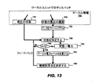
図13は、ローカルユニットで、その負荷の機械設定点をディスパッチする実施形態を示すフロー図である。最初のステップ740で、特定の負荷におけるローカルユニットのコンピュータは、負荷の特性を含むローカル情報を取得する。さらに、ステップ744で、ローカルユニットは、例えば、ローカル負荷における電力網の現在の周波数を、周波数計674を用いて検出することにより、現在の状態を特定する。また、電圧、圧力、スループット、ローカル温度、電流など、他のローカル状態を特定することもできる。一般的に、ステップ744では、負荷の状態を特定するために、ローカルエネルギー負荷における任意のローカル信号を確認または測定する。ステップ748では、特定の状態の最近の履歴をローカルユニットによって取得し、例えば、過去24時間にわたる、ローカル負荷における電力網の周波数を取得する。
[Flow diagram of local dispatch]
FIG. 13 is a flow diagram illustrating an embodiment in which a local unit dispatches a machine set point for its load. In a
ステップ752で、この履歴情報を、測定誤差に対処することなどにより、クリーニングすることができる。ステップ756では、現在の状態および履歴を用いて、ローカル負荷における電力網の有効な現在の状態を特定する。例えば、ローカル周波数が極めて変動しやすい場合は、ステップ756で、ローカル電力レベル計算のためにより望ましい有効な周波数を推定するために、ステップ744からの測定された瞬時周波数の時間平均を用いることができる。
In
周波数が特定されたら、ローカルユニットのコンピュータは、以前に中央ユニットから送られたローカルディスパッチパラメータ760を取得する。これらのパラメータには、ローカル負荷で電力網の特定の周波数を検出したときにローカル負荷は自身の電力をいかに低減すべきか規定する周波数−電力マップが含まれる。特定された状態(電力網周波数)と、周波数−電力マップとを比較する。特定された状態が、マップで指示された周波数範囲内に(または、指示された周波数で)ある場合には、ステップ762で、負荷をアクティブにすると決定する。そうでない場合は、ローカルユニットは、引き続き、状態を特定し、それをディスパッチパラメータと比較する。例えば、図3は、周波数−電力マップを象徴的に示しており、この場合、電力網の周波数が約49.87Hzから49.83Hzまで低下するときに、負荷2は、自身の電力消費を線形的に総量で4MW低減させなければならない。
Once the frequency is specified, the local unit computer obtains the
ステップ764で、ローカルユニットは、この周波数−電力マップを用いて、負荷の新たなローカル電力レベルはどうであるべきか決定する。例えば、ローカルユニットは、過去と現在の電力網周波数に基づいて、基準電力レベルRとアクティブ化される電力量Pの両方を決定する。この場合、負荷が適合すべき新たなローカル電力レベル(すなわち、絶対電力レベル)は、R−Pである(実際には、負荷は、可能な限り大きい電力量であって、かつR−Pよりも小さい電力量を消費すべきである)。例えば、負荷が10MWを消費しており、2MWがアクティブ化される場合は、新たなローカル電力レベルは8MWである。 At step 764, the local unit uses this frequency-power map to determine what the new local power level of the load should be. For example, the local unit determines both the reference power level R and the amount of power P to be activated based on past and current power grid frequencies. In this case, the new local power level (ie absolute power level) to which the load should adapt is RP (in practice, the load is the highest amount of power possible and more than RP). Should also consume a small amount of power). For example, if the load is consuming 10 MW and 2 MW is activated, the new local power level is 8 MW.
ローカル電力レベルが決定されたら、ステップ768で、ローカルディスパッチアルゴリズムを用いて、このローカル負荷を構成する機械の各々について、実際の機械設定点を決定する。ローカルディスパッチアルゴリズムおよび実際の機械設定点は、負荷のタイプによって異なる。例えば、負荷は、10台の異なるモータを含む場合があり、その各々は、独立に遮断することができる。あるいは、負荷は、連続可変の電力レベルを有する単一の機械、またはオンもしくはオフのいずれかとすることができる機械、で構成されることがある。ディスパッチアルゴリズムの目的は、負荷の電力レベルが可能な限り厳密に新たな電力レベルに一致するように、負荷の機械を制御することである。機械の設定点として、機械をオンまたはオフのどちらかとすること、機械の可変電力レベル、機械の温度、システムの圧力、機械の電流、現にアクティブ化される部分負荷の数、を含むことができる。
Once the local power level is determined, at
その電力が連続的に可変である単一の機械で構成される負荷の場合、ローカルディスパッチアルゴリズムにとって、機械設定点を決定することは、例えば、「周波数の.01Hzの低下ごとに電力を1MW低減する」とするなど、簡単なことであり得る。また、その電力がオンまたはオフのいずれかである複数の機械で構成される負荷の場合であっても、ディスパッチングは、例えば、「周波数の.01Hzの低下ごとに1つの機械をオフにする」とするなど、比較的簡単であり得る。その電力がオンまたはオフのいずれかである単一の機械(または複数の機械)を有する負荷の場合は、他の技術を用いて、新たな電力レベルに適合するように、機械設定点を決定する。電力網周波数が49.89Hzに低下したときのバイナリ負荷の例であって、指令により、新たな電力レベルは、3MWではなく、2MWでなければならない例について考える。電力網運用者は、一般的には、20秒の平均を用いて電力を測定するので、20秒間の電力レベルで2MWの平均電力レベルの結果を達成するように、この負荷の3MW機械をオンとオフに切り替えることが可能である。この例では、負荷のローカルディスパッチアルゴリズムにより、負荷は、20秒ごとに、その時間の2/3はオンであり、その時間の1/3はオフであるように、機械設定点を決定する。 In the case of a load consisting of a single machine whose power is continuously variable, for the local dispatch algorithm, determining the machine set point is, for example, “reducing power by 1 MW for every .01 Hz decrease in frequency. It can be as simple as “do”. Even in the case of a load consisting of multiple machines whose power is either on or off, dispatching, for example, “turns off one machine for every .01 Hz drop in frequency. ”And so on. For loads with a single machine (or multiple machines) whose power is either on or off, use other techniques to determine the machine setpoint to match the new power level To do. Consider an example of a binary load when the power grid frequency drops to 49.89 Hz, where the command requires a new power level to be 2 MW instead of 3 MW. Grid operators typically measure power using an average of 20 seconds, so turn on a 3 MW machine for this load to achieve a 2 MW average power level result at a power level of 20 seconds. It can be switched off. In this example, the load local dispatch algorithm determines the machine set point so that every 20 seconds, the load is on for 2/3 of the time and off for 1/3 of the time.
他の例では、負荷の電力消費は、負荷に流れる電流を設定することによって制御できると仮定する。電圧をV、電流と電圧との間の測定された位相角をφとすると、電流の設定点は、(R−P)/(V*cos(φ))となる。他の例では、負荷は、n通りの電力レベルを有し、これは、1(最低)からn(最高)までの範囲の変数$Xを使用して、フィールドバスプロトコルを用いてプラグラム可能であると仮定する。変数$Xの最良の値を決定するために、ローカルユニットは、可用電力レベルの各々について、低いものから高いものへと反復処理し、結果として得られる電力レベルは、依然としてR−Pよりも小さくなるかどうかチェックする。レベルmが、結果として得られる電力レベルがR−Pよりも小さくならない最初のレベルであると仮定すると、負荷の設定点は、$X=(m−1)であると決定される。 In another example, assume that the power consumption of the load can be controlled by setting the current flowing through the load. If the voltage is V and the measured phase angle between the current and voltage is φ, then the current set point is (RP) / (V * cos (φ)). In another example, the load has n power levels, which can be programmed using the fieldbus protocol using a variable $ X ranging from 1 (lowest) to n (highest). Assume that there is. To determine the best value of variable $ X, the local unit iterates from low to high for each available power level, and the resulting power level is still less than RP. Check if it becomes. Assuming level m is the first level where the resulting power level is not less than RP, the load set point is determined to be $ X = (m−1).
新たな機械設定点が決定されたら、次に、負荷は、例えば、フィールドバスプロトコル678を用いて、これらの設定点を機械に伝達することにより、その結果、その電力を低減する。周波数シフトを検出してから電力を低減するまでの応答時間は、機器(一部の機器は「ラグ」を有するか、または、弊害を引き起こさないために、その消費を徐々に減少させる必要がある)と、通信待ち時間およびソフトウェアの計算時間に依存する。機器については、その範囲は、0s(一部の電気エンジン)から1日(接続された多くの部品を備える複雑なプロセス)であり、通信およびソフトウェアについては、その応答は、10msのオーダである。典型的には、総応答時間は、数秒のオーダである。
Once the new machine setpoints are determined, the load then communicates these setpoints to the machine using, for example,
さらに、設定点によって達成される電力が、計算されたローカル電力レベルに可能な限り厳密に一致することを確認するために、フィードバックが供給される。一致していない場合は、ループ756〜768を再度実行する。例えば、電力を調整するために電流設定点を用いる場合は、必ずしも線形関係ではないので、フィードバックを用いることが必要となる。また、電力が低減されたら、電力網の周波数が変わる可能性がある(ポートフォリオ内の十分な負荷で、それらの電力消費を成功裏に低減した場合、おそらく周波数は増加する)。従って、ローカルユニットは、電力網の状態を継続的に確認し、必要に応じて、新たなローカル電力レベルを計算する。中央ユニットから新規のディスパッチパラメータ760を受け取ることは、常にあり得る。
In addition, feedback is provided to ensure that the power achieved by the set point matches the calculated local power level as closely as possible. If they do not match, the
具体的な一実施形態では、ローカルユニットにおいて、電力網の状態およびローカル電力レベルは、ほぼ毎秒、リアルタイムで特定される。このとき、ディスパッチアルゴリズムは、機械設定点を直ちに決定してディスパッチし、(アクティブである間は)毎秒、これを実行し続ける。 In a specific embodiment, in the local unit, the state of the power grid and the local power level are specified in real time, approximately every second. At this time, the dispatch algorithm immediately determines and dispatches the machine set point and continues to execute this every second (while active).
[再構成のフロー図]
図14は、本発明の再構成プロセスを示すフロー図である。構成が集中的に実施されて、ディスパッチパラメータが各負荷に送られた後は、再構成が必要であるかどうか判断するために、負荷の状態を頻繁に監視することが効果的である。頻繁に負荷を再構成する(これは、多くの資源を要し、かつリスクの可能性がある)のではなく、監視を頻繁に実施し(これは、最小限のデータを用いて、高速で実行可能である)、再構成は、必要な場合にのみ実行する。一実施形態では、監視は、10秒ごとに実施される。他の実施形態では、中央システムによるローカル監視へのサブスクリプションによって、データの変更のみが中央システムに伝えられる。
[Reconfiguration flow diagram]
FIG. 14 is a flow diagram illustrating the reconstruction process of the present invention. After configuration has been centrally performed and dispatch parameters have been sent to each load, it is effective to frequently monitor the status of the load to determine if reconfiguration is necessary. Rather than reconfiguring the load frequently (which is resource intensive and potentially risky), monitoring is performed frequently (which uses minimal data and is fast) Perform reconfiguration only when necessary. In one embodiment, monitoring is performed every 10 seconds. In other embodiments, subscription to local monitoring by the central system only communicates data changes to the central system.
図示のように、ステップ704〜720は、中央ロケーションで実行されて、その結果、各負荷に対するディスパッチパラメータのカスタムセットが得られ、それらは、例えば、ローカルユニット670〜690に配布される。ローカル負荷におけるローカルユニット670は、コンピュータを有し、これにより、周波数計および電力計からの入力を受け取り、中央ユニットから受け取ったディスパッチパラメータのそのセットを分析し、機械設定点を決定し、そして(例えば、フィールドバスプロトコルを用いて)ローカル負荷で電力を低減するように指示する。
As shown, steps 704-720 are performed at a central location, resulting in a custom set of dispatch parameters for each load, which are distributed to local units 670-690, for example. The
中央ユニットで、各負荷からフィードバック704を受け取り、これにより、ステップ709で、各負荷の内部状態を継続的に監視する。例えば、各負荷の瞬時電力消費および状態情報を監視する。ステップ713における非ローカル監視には、上記の非ローカルデータのいずれを含むこともできるが、典型的には電力網周波数のみが含まれる。
The central unit receives
ステップ715で、中央ユニットは、再構成を実施すべきかどうか、すなわち、異なる周波数サブバンドまたは異なる電力レベルで負荷がアクティブ化されるように、ポートフォリオの負荷を再構成すべきであると、ローカルまたは非ローカル状態の変化が指示しているかどうか、判断する。このステップでは、さらに、各負荷の現在のディスパッチパラメータも考慮される。このステップにおける監視の利点は、完全な再構成を実施すべきかどうか決定するのに必要とされるのは、最小限のデータのみであることである。例えば、ステップ715では、(ステップ764で決定された)各負荷の元のローカル電力レベルを、各負荷の瞬時電力消費と比較する。負荷が使用している電力のほうが少ない(例えば、前の構成でのその電力レベルの約90%よりも少ない)場合は、再構成を実施する。負荷が消費している電力のほうが多い場合、これは可用性の増加を意味するので、再構成はトリガされない。
At
他の例では、何らかの理由(例えば、ユニット670におけるコンピュータクラッシュ、機械の故障、または負荷の所有者による判断)で、負荷が使用不能となったこと、または使用不能となること、が検出された場合にも、再構成が示唆され得る。監視は頻繁に実施されているとしても、ポートフォリオを頻繁に再構成することは、システムの安定性を強化するためには望ましくない場合がある。一実施形態において、ステップ715で使用されるパラメータによって、再構成を、平均して1日1回に制限する。
In other examples, it has been detected that the load has become unusable or unusable for some reason (eg, a computer crash in
再構成を実施すべきである場合は、ステップ716で、中央ユニットにおいて新たに負荷の構成を実施する。例えば、図6は、ローカルの変化によって、結果的に負荷が新たに順序付けされることを示している。さらに、この順序付けに、履歴データベース720を用いて情報を提供することもでき、それには、図4、5、7に示すような周波数の確率情報、過去の負荷順序付け情報が含まれる。負荷が再構成され(そして各負荷に新たな周波数−電力マップが割り当てられ)たら、ディスパッチパラメータの新たなセットが、通信ネットワーク170を介してローカルユニットの各々に送られる。
If reconfiguration is to be performed, a new load configuration is performed at the central unit at
図示のように、ローカルユニット670〜690は、アクティブ化の能力の降順で、上から下に順序付けされて、象徴的に示されている。すなわち、より高い電力可用性、より高い電力安定性、より高速の応答時間を有する特定の負荷は、より低い電力可用性、より低い電力安定性、もしくは、より低速の応答時間、またはこれら3つの組み合わせを有する負荷よりも、上位に順序付けされる可能性がある。また、能力がより高いユニットには、周波数偏差が生じる可能性がより高い周波数サブドメインが割り当てられ、これにより、可能性が高い周波数シフトに対して、より高速の応答を可能とする。 As shown, the local units 670-690 are shown symbolically, ordered from top to bottom, in descending order of activation capability. That is, a particular load with higher power availability, higher power stability, faster response time can result in lower power availability, lower power stability, or slower response time, or a combination of the three It may be ordered higher than the load it has. Also, higher capacity units are assigned frequency subdomains that are more likely to have frequency deviations, thereby enabling faster response to more likely frequency shifts.
[電力網周波数の増加または他の電力網パラメータへの適用可能性]
前述のように、本発明は、(ポートフォリオの電力消費の低減を必要とする)電力網周波数の低下に適用できるだけではなく、(ポートフォリオの電力消費の増加を必要とする)電力網周波数の増加にも適用可能である。例えば、図3は、50Hz未満の周波数帯域への周波数低下に応答する負荷のスタッキングを示しているが、50Hz超の周波数増加に応答するように、負荷をスタックすることができる。その場合は、(電力可用性が最も高い、安定性が最も高い、高速応答時間、など)最も能力の高い負荷が、より低周波数に、または確率の高い周波数領域周辺に、位置付けられる。また、図7では、点502の左側に、負荷522〜526のスタッキングを示しているが、電力網周波数が通常よりも高く上昇したときの状況に対処するために、点502の右側に、負荷をスタックすることができる。さらに、契約条件734では、(例えば、ヨーロッパでは)50.10Hz〜50.20Hzの周波数帯域にあるときに、負荷のポートフォリオがアクティブ化されること、および、周波数が50.20Hzに達した場合は(例えば)総量で10MW余分にポートフォリオで消費すること、を要求することができる。図11は、電力網周波数が低下したときにアクティブ化された負荷で電力を制限する文脈で説明されたが、周波数が上昇したときの予定された電力を、アクティブ化された負荷で消費することもできることは、当業者であれば理解できるであろう。また、図12は、周波数が上昇を開始した後に遅延を導入する遅延パラメータについて説明しているが、そのような遅延パラメータを、周波数が低下するときに用いることもできる。概して、当業者であれば、本開示を読解することで、電力網周波数が正常値を超えて上昇したときにポートフォリオの電力消費が増加するようにポートフォリオの負荷を管理するために、本発明を実施することが可能であろう。
[Increase of grid frequency or applicability to other grid parameters]
As mentioned above, the present invention can be applied not only to lowering the grid frequency (which requires a reduction in portfolio power consumption) but also to increasing the grid frequency (which requires an increase in portfolio power consumption). Is possible. For example, while FIG. 3 shows load stacking in response to a frequency drop to a frequency band below 50 Hz, the load can be stacked to respond to a frequency increase above 50 Hz. In that case, the most capable load (highest power availability, highest stability, fast response time, etc.) is located at a lower frequency or around a probable frequency region. In FIG. 7, stacking of the
さらに、本発明が適用される電力網パラメータの他の例は、電圧である。実際に、電力網では、ローカルレベルまたはグローバルレベルで、電圧低下/ノイズが発生する可能性があり、同じ方法論で柔軟な電力資源のポートフォリオを用いて、数秒以内で電力網が最適に改善されることは明らかである。また、測定信号以外の、負荷で受信される信号を用いることもできる。例えば、電力供給者も、例えば自身のポートフォリオのバランスを維持するために、高速応答時間を有する電力柔軟性に関心がある。このような設定で使用される場合、ローカル負荷レベルでのアクティブ化は、電力網周波数の測定によるのではなく、例えば、電力供給者が送信する外部信号によってトリガされる。 Furthermore, another example of the power grid parameter to which the present invention is applied is voltage. In fact, in power grids, voltage drops / noise can occur at local or global levels, and using the same methodology and a flexible portfolio of power resources, the power grid can be optimally improved within seconds. it is obvious. Further, a signal received by a load other than the measurement signal can be used. For example, power suppliers are also interested in power flexibility with fast response times, for example to maintain balance in their portfolio. When used in such a setting, activation at the local load level is not triggered by the measurement of the grid frequency, but is triggered, for example, by an external signal transmitted by the power supplier.
[天然ガス網への適用可能性] [Applicability to natural gas network]
前述のように、本発明の実施形態は、天然ガスによってエネルギーを供給する天然ガス網(およびその個々の負荷)にも適用可能である。この実施形態では、ガス網の状態とはガス圧力であり、このガス圧力が、各ローカル負荷で検出される。ガス圧力が低下した場合には、ローカル負荷で、この低下を検出し、中央ユニットから送られたローカルディスパッチパラメータのセットを用いて、天然ガスのその消費を低減させる。この場合、ディスパッチパラメータは、圧力の低下に応じて負荷が使用する天然ガス(力)をどれほど減少させる必要があるのかを規定する圧力−力マップを提供するものである。また、ガス網のガス圧力が高まった場合にも、本発明を用いることができる。概して、負荷は、ガス網に接続されているとともに、それに接続されたローカル制御システムを有しているか、またはローカル制御システムに接続可能であるか、いずれかであれば、そのガス負荷は、本発明と共に使用するのに適している。 As mentioned above, embodiments of the present invention are also applicable to natural gas networks (and their individual loads) that are supplied with energy by natural gas. In this embodiment, the state of the gas network is the gas pressure, which is detected at each local load. If the gas pressure drops, the local load detects this drop and uses the set of local dispatch parameters sent from the central unit to reduce its consumption of natural gas. In this case, the dispatch parameter provides a pressure-force map that defines how much the natural gas (force) used by the load needs to be reduced as the pressure drops. The present invention can also be used when the gas pressure in the gas network increases. Generally, a load is connected to a gas network and has a local control system connected to it or is connectable to a local control system, so that the gas load is Suitable for use with the invention.
[コンピュータシステムの実施形態]
図15Aおよび15Bは、本発明の実施形態を実施するのに適したコンピュータシステム900を示している。図15Aは、コンピュータシステムの1つの可能な物理的形態を示している。当然のことながら、コンピュータシステムは、集積回路、プリント回路基板、(携帯電話機またはPDAなどの)小型ハンドヘルドデバイス、パーソナルコンピュータ、またはスーパーコンピュータなど、数多くの物理的形態をとることができる。コンピュータシステム900は、モニタ902、ディスプレイ904、ハウジング906、ディスクドライブ908、キーボード910、およびマウス912を備える。ディスク914は、コンピュータシステム900との間でデータを転送するように用いられるコンピュータ可読媒体である。
[Computer System Embodiment]
15A and 15B illustrate a
図15Bは、コンピュータシステム900のブロック図の一例である。システムバス920には、様々なサブシステムが接続されている。(中央処理装置またはCPUとも呼ばれる)プロセッサ(複数の場合もある)922は、メモリ924を含む記憶装置に接続されている。メモリ924には、ランダムアクセスメモリ(RAM)および読み出し専用メモリ(ROM)が含まれる。当技術分野で周知のように、ROMは、データおよび命令をCPUに対して一方的に転送するように機能し、RAMは、一般に、データおよび命令を双方向に転送するように用いられる。これらのタイプのメモリはどちらも、後述のコンピュータ可読媒体のうちの任意の適切なものを含むことができる。さらに、固定ディスク926が、CPU 922に対して双方向に接続されており、これは、追加のデータ記憶容量を提供するものであって、同じく後述のコンピュータ可読媒体のいずれかを含むことができる。固定ディスク926は、プログラム、データなどを保存するために使用することができ、一般的には、主記憶装置よりも低速である(ハードディスクなどの)補助記憶媒体である。なお、固定ディスク926内に保持されている情報は、適切な場合に、標準的な方法でメモリ924内に仮想メモリとして組み込むことができることは、理解されるであろう。リムーバブルディスク914は、後述のコンピュータ可読媒体のいずれかの形態をとることができる。
FIG. 15B is an example of a block diagram of the
CPU 922は、さらに、ディスプレイ904、キーボード910、マウス912、およびスピーカ930など、様々な入力/出力装置に接続されている。一般に、入力/出力装置は、ビデオディスプレイ、トラックボール、マウス、キーボード、マイクロフォン、タッチ式ディスプレイ、トランスデューサカードリーダ、磁気もしくは紙テープリーダ、タブレット、スタイラス、音声もしくは手書き認識装置、バイオメトリクスリーダ、または他のコンピュータのいずれかであり得る。CPU 922は、任意選択的に、ネットワークインタフェース940を用いて、他のコンピュータまたは通信ネットワークに接続され得る。このようなネットワークインタフェースを用いることで、CPUが、上記の方法ステップを実行する過程で、ネットワークから情報を受信し得ること、またはネットワークに情報を出力し得ること、が企図される。また、本発明の実施形態の方法は、CPU 922で単独で実行することができ、またはインターネットなどのネットワークを介して処理の一部を共有するリモートCPUと連携して実行することができる。
The
なお、本発明の実施形態は、さらに、種々のコンピュータ実施オペレーションを実行するためのコンピュータコードを含むコンピュータ可読媒体を備えた、コンピュータストレージプロダクトに関する。媒体およびコンピュータコードは、本発明の目的のために特別に設計および構成されたものとすることができ、またはコンピュータソフトウェア技術分野の当業者にとって周知かつ入手可能な種類のものとすることができる。コンピュータ可読媒体の例として、限定するものではないが、ハードディスク、フロッピーディスク(登録商標)、磁気テープのような磁気媒体、CD−ROMおよびホログラフィックデバイスのような光学媒体、フロプティカルディスクのような光磁気媒体、さらに、特定用途向け集積回路(ASIC)、プログラマブルロジックデバイス(PLD)、ROMおよびRAMデバイスのような、プログラムコードを記憶および実行するように特別に構成されたハードウェアデバイス、が含まれる。コンピュータコードの例として、コンパイラによって生成されるような機械語コード、およびコンピュータによってインタプリタを用いて実行される高級言語コードを含むファイル、が挙げられる。 Note that embodiments of the present invention further relate to a computer storage product comprising a computer readable medium including computer code for performing various computer-implemented operations. The media and computer code may be specially designed and configured for the purposes of the present invention, or may be of a type well known and available to those skilled in the computer software art. Examples of computer readable media include, but are not limited to, hard disks, floppy disks, magnetic media such as magnetic tape, optical media such as CD-ROMs and holographic devices, and floppy disks. And magneto-optical media, as well as hardware devices specially configured to store and execute program code, such as application specific integrated circuits (ASICs), programmable logic devices (PLDs), ROM and RAM devices included. Examples of computer code include machine language code as generated by a compiler and files containing high-level language code executed by a computer using an interpreter.
上記の発明は、明確な理解を目的として、ある程度詳細に記載しているが、添付の請求項の範囲内でいくらかの変更および変形を実施することができることは明らかであろう。よって、記載された実施形態は例示とみなされるべきであって、限定するものではなく、また、本発明は、本明細書で提示した詳細に限定されるべきではなく、添付の請求項およびその均等物の全範囲によって規定されるべきである。
本発明は、以下の適用例としても実現可能である。
[適用例1]
エネルギー分配網に接続されて、それぞれ電力消費を有するエネルギー負荷からなるポートフォリオの電力消費を変更する方法であって、
前記エネルギー負荷の各々において前記分配網上で測定可能な信号に対する前記エネルギー負荷の前記ポートフォリオの所望の電力応答を示すポートフォリオ応答関数を、中央ユニットで受け取ることと、
前記信号の変化に応じた電力変更量を示す前記エネルギー負荷の各々のローカル応答関数を、前記中央ユニットで決定することと、
前記ローカル応答関数を、それぞれ対応する前記エネルギー負荷に対して、前記中央ユニットから送信することと、
前記送信の後に、前記エネルギー負荷の各々によって、それぞれ該エネルギー負荷において前記信号が変化したことを検出することと、
前記検出に応答して、各エネルギー負荷で独立に、それぞれ前記ローカル応答関数に従った前記電力変更量で、自身の電力消費を変更することであって、前記電力変更量の組み合わせによって、前記所望の電力応答を実現することと、を含む方法。
[適用例2]
適用例1に記載の方法であって、
前記エネルギー負荷は、電気負荷であり、
前記エネルギー分配網は、配電網であり、
前記信号は、前記配電網の周波数である、方法。
[適用例3]
適用例2に記載の方法であって、
前記検出された周波数が、前記配電網の通常の動作周波数よりも低い場合、前記方法は、更に、
前記検出に応答して、各電気負荷で独立に、前記電力変更量で、自身の電力消費を低減することであって、電気負荷の前記ポートフォリオの電力消費を、前記所望の電力応答によって低減させることを含む、方法。
[適用例4]
適用例2に記載の方法であって、
前記検出された周波数が、前記配電網の通常の動作周波数よりも高い場合、前記方法は、更に、
前記検出に応答して、各電気負荷で独立に、前記電力変更量で、自身の電力消費を増加することであって、電気負荷の前記ポートフォリオの電力消費を、前記所望の電力応答によって増加させることを含む、方法。
[適用例5]
適用例1に記載の方法であって、
前記エネルギー分配網の分配網運用者は、前記信号が、ある信号範囲で変化したときに、前記エネルギー負荷の前記ポートフォリオの前記電力消費が、前記所望の電力量で変更されることを要求する、方法。
[適用例6]
適用例1に記載の方法であって、更に、
前記検出に応答して、各エネルギー負荷で独立に、前記中央ユニットから入力を受けることなく、自身の電力消費をリアルタイムで変更することを含む、方法。
[適用例7]
適用例6に記載の方法であって、更に、
各エネルギー負荷で独立に、秒のオーダで、自身の電力消費を変更することを含む、方法。
[適用例8]
適用例1に記載の方法であって、更に、
各エネルギー負荷の電力消費を、それぞれ該エネルギー負荷の境界条件に違反することなく、前記電力変更量で変更することを含む、方法。
[適用例9]
適用例1に記載の方法であって、
前記エネルギー負荷は、ガス負荷であり、
前記エネルギー分配網は、ガス分配網であり、
前記信号は、前記ガス分配網の圧力である、方法。
[適用例10]
適用例1に記載の方法であって、
前記ポートフォリオ応答関数は線形関数である、方法。
[適用例11]
エネルギー分配網に接続されて、それぞれ電力消費を有するエネルギー負荷からなるポートフォリオの電力消費を変更するためのシステムであって、
前記エネルギー負荷の各々において前記分配網上で測定可能な信号に対する前記エネルギー負荷の前記ポートフォリオの所望の電力応答を示すポートフォリオ応答関数を受け取るように構成された中央演算ユニットであって、更に、前記信号の変化に応じた電力変更量を示す前記エネルギー負荷の各々のローカル応答関数を決定するように構成された中央演算ユニットと、
前記中央演算ユニットに接続されたディスパッチ演算ユニットであって、前記ローカル応答関数を、それぞれ対応する前記エネルギー負荷に対して、前記中央演算ユニットから送信するように構成されたディスパッチ演算ユニットと、
前記エネルギー負荷の各々に配置された信号検出器であって、前記送信の後に、前記エネルギー負荷の各々で、それぞれ該エネルギー負荷において前記信号が変化したことを検出するように構成された信号検出器と、
前記エネルギー負荷の各々に配置されたローカル演算ユニットであって、前記検出に応答して、それぞれ該エネルギー負荷の電力消費を、独立に、それぞれ前記ローカル応答関数に従った前記電力変更量で変更し、前記電力変更量の組み合わせによって前記所望の電力応答を実現するように構成されたローカル演算ユニットと、
を備える方法。
[適用例12]
適用例11に記載のシステムであって、
前記エネルギー負荷は、電気負荷であり、
前記エネルギー分配網は、配電網であり、
前記信号は、前記配電網の周波数である、システム。
[適用例13]
エネルギー分配網に接続されて、それぞれ電力消費を有するエネルギー負荷からなるポートフォリオの電力消費を変更する方法であって、
前記エネルギー負荷の各々において前記分配網上で測定可能な信号に対する前記エネルギー負荷の前記ポートフォリオの所望の電力応答を示すポートフォリオ応答関数を、中央ユニットで受け取ることと、
各エネルギー負荷について、それぞれ該エネルギー負荷が、特定の信号値に対応する可用電力量を有する確率を示す項を有する最適化関数を受け取ることと、
前記信号の変化に応じた電力変更量を示すそれぞれの前記エネルギー負荷のローカル応答関数を生成するために、前記最適化関数を最大化することと、
前記ローカル応答関数を、それぞれ対応する前記エネルギー負荷に対して、前記中央ユニットから送信することであって、これにより、前記ローカル応答関数の合成演算によって前記ポートフォリオ応答関数を実現することと、を含む方法。
[適用例14]
適用例13に記載の方法であって、更に、
前記送信の後に、前記エネルギー負荷の各々によって、それぞれ該エネルギー負荷において前記信号が正常値から変化したことを検出することと、
前記検出に応答して、各エネルギー負荷で独立に、それぞれ該エネルギー負荷の前記ローカル応答関数によって規定される前記電力変更量で、自身の電力消費を変更することと、を含む、方法。
[適用例15]
適用例13に記載の方法であって、
前記エネルギー負荷を、前記負荷の各々の電力可用性の降順で順序付けることをさらに含む、方法。
[適用例16]
適用例15に記載の方法であって、
前記電力可用性は、各エネルギー負荷が、それぞれ該エネルギー負荷の境界条件に違反することなく、それぞれ前記電力変更量で、自身の電力消費を今後に変更可能である確率である、方法。
[適用例17]
適用例13に記載の方法であって、
前記最適化関数は、各エネルギー負荷について、それぞれ該エネルギー負荷の前記電力消費を変更する応答時間が、分配網運用者が要求する応答時間よりも長い確率を示す負の項をさらに有する、方法。
[適用例18]
適用例13に記載の方法であって、
前記最適化関数は、各エネルギー負荷について、それぞれ該エネルギー負荷が、前記電力変更量のある割合よりも少ない可用電力量を有する確率を示す負の項をさらに有する、方法。
[適用例19]
適用例13に記載の方法であって、
前記エネルギー分配網は、配電網であり、
前記エネルギー負荷は、電気負荷であり、
前記信号は、前記配電網の周波数である、方法。
[適用例20]
適用例19に記載の方法であって、
前記周波数が、前記配電網の通常の動作周波数よりも低い場合、前記方法は、更に、
それぞれの前記電気負荷が、それぞれ前記電力変更量で、自身の電力消費を今後に低減可能である確率の降順で、前記電気負荷を順序付けること、
を含み、
より高い確率を有する負荷は、前記周波数のより高い値に応答するローカル応答関数を有する、方法。
[適用例21]
適用例19に記載の方法であって、
前記周波数が、前記配電網の通常の動作周波数よりも高い場合、前記方法は、更に、
それぞれの前記電気負荷が、それぞれ前記電力変更量で、自身の電力消費を今後に低減可能である確率の降順で、前記電気負荷を順序付けること、
を含み、
より高い確率を有する負荷は、前記周波数のより低い値に応答するローカル応答関数を有する、方法。
[適用例22]
適用例13に記載の方法であって、
前記エネルギー分配網の分配網運用者は、前記信号がある信号範囲で変化したときに、前記エネルギー負荷の前記ポートフォリオの前記電力消費が、前記所望の電力量で変更されることを要求する、方法。
[適用例23]
適用例13に記載の方法であって、
前記エネルギー負荷は、ガス負荷であり、
前記エネルギー分配網は、ガス分配網であり、
前記信号は、前記ガス分配網の圧力である、方法。
[適用例24]
適用例13に記載の方法であって、
前記ポートフォリオ応答関数は線形関数である、方法。
[適用例25]
エネルギー分配網に接続されて、それぞれ電力消費を有するエネルギー負荷からなるポートフォリオの電力消費を変更するためのシステムであって、
前記エネルギー負荷の各々において前記分配網上で測定可能な信号に対する前記エネルギー負荷の前記ポートフォリオの所望の電力応答を示すポートフォリオ応答関数を受け取るように構成された中央演算ユニットであって、更に、各エネルギー負荷について、それぞれ該エネルギー負荷が、特定の信号値に対応する可用電力量を有する確率を示す項を有する最適化関数を受け取るように構成された中央演算ユニットと、
前記中央演算ユニットに接続されたアルゴリズム演算ユニットであって、前記信号の変化に応じた電力変更量を示すそれぞれの前記エネルギー負荷のローカル応答関数を生成するために、前記最適化関数を最大化するように構成されたアルゴリズム演算ユニットと、
前記中央演算ユニットに接続されたディスパッチ演算ユニットであって、前記ローカル応答関数を、それぞれ対応する前記エネルギー負荷に対して、前記中央演算ユニットから送信し、前記ローカル応答関数の合成演算によって、記ポートフォリオ応答関数を実現するように構成されたディスパッチ演算ユニットと、
を備える、方法。
[適用例26]
適用例25に記載のシステムであって、
前記エネルギー分配網は、配電網であり、
前記エネルギー負荷は、電気負荷であり、
前記信号は、前記配電網の周波数である、システム。
Although the foregoing invention has been described in some detail for purposes of clarity of understanding, it will be apparent that certain changes and modifications may be practiced within the scope of the appended claims. Accordingly, the described embodiments are to be regarded as illustrative and not restrictive, and the invention should not be limited to the details presented herein, but the appended claims and their Should be defined by the full range of equivalents.
The present invention can also be realized as the following application examples.
[Application Example 1]
A method for changing the power consumption of a portfolio consisting of energy loads each connected to an energy distribution network and having a power consumption,
Receiving at a central unit a portfolio response function indicative of a desired power response of the portfolio of the energy load to a signal measurable on the distribution network at each of the energy loads;
Determining, at the central unit, a local response function of each of the energy loads indicating an amount of power change in response to a change in the signal;
Transmitting the local response function from the central unit for each corresponding energy load;
After the transmission, detecting by each of the energy loads that the signal has changed at the energy load respectively;
In response to the detection, each energy load independently changes its own power consumption by the power change amount according to the local response function, and the desired change is made by the combination of the power change amounts. Realizing a power response of the method.
[Application Example 2]
A method described in application example 1,
The energy load is an electrical load;
The energy distribution network is a distribution network;
The method, wherein the signal is a frequency of the distribution network.
[Application Example 3]
A method described in application example 2,
If the detected frequency is lower than the normal operating frequency of the distribution network, the method further comprises:
In response to the detection, independently at each electrical load, reducing the power consumption of the portfolio with the amount of power change, the power consumption of the portfolio of electrical loads being reduced by the desired power response Including the method.
[Application Example 4]
A method described in application example 2,
If the detected frequency is higher than the normal operating frequency of the distribution network, the method further comprises:
In response to the detection, independently increasing the power consumption of the portfolio of electrical loads by the desired power response, independently increasing each power load with the amount of power change. Including the method.
[Application Example 5]
A method described in application example 1,
The distribution network operator of the energy distribution network requests that the power consumption of the portfolio of the energy load be changed by the desired amount of power when the signal changes in a signal range. Method.
[Application Example 6]
The method according to application example 1, further comprising:
Responsive to the detection, the method includes changing its power consumption in real time independently of each energy load without receiving input from the central unit.
[Application Example 7]
The method according to Application Example 6, further comprising:
A method comprising changing its own power consumption, on the order of seconds, independently at each energy load.
[Application Example 8]
The method according to application example 1, further comprising:
Changing the power consumption of each energy load by the amount of power change without violating boundary conditions of the energy load.
[Application Example 9]
A method described in application example 1,
The energy load is a gas load;
The energy distribution network is a gas distribution network;
The method, wherein the signal is the pressure of the gas distribution network.
[Application Example 10]
A method described in application example 1,
The method wherein the portfolio response function is a linear function.
[Application Example 11]
A system connected to an energy distribution network for changing the power consumption of a portfolio of energy loads each having a power consumption,
A central processing unit configured to receive a portfolio response function indicative of a desired power response of the portfolio of the energy load to a signal measurable on the distribution network at each of the energy loads, further comprising the signal A central processing unit configured to determine a local response function of each of the energy loads indicating an amount of power change in response to changes in
A dispatch processing unit connected to the central processing unit, the dispatch function unit configured to transmit the local response function to the corresponding energy load from the central processing unit;
A signal detector disposed at each of the energy loads, the signal detector configured to detect after the transmission, at each of the energy loads, that the signal has changed at the energy load, respectively. When,
A local computing unit disposed in each of the energy loads, wherein in response to the detection, the power consumption of the energy load is independently changed by the power change amount according to the local response function, respectively. A local arithmetic unit configured to realize the desired power response by a combination of the power change amounts;
A method comprising:
[Application Example 12]
The system according to application example 11,
The energy load is an electrical load;
The energy distribution network is a distribution network;
The system, wherein the signal is a frequency of the distribution network.
[Application Example 13]
A method for changing the power consumption of a portfolio consisting of energy loads each connected to an energy distribution network and having a power consumption,
Receiving at a central unit a portfolio response function indicative of a desired power response of the portfolio of the energy load to a signal measurable on the distribution network at each of the energy loads;
For each energy load, each receiving an optimization function having a term indicating a probability that the energy load has an amount of available power corresponding to a particular signal value;
Maximizing the optimization function to generate a local response function for each of the energy loads that indicates a power change in response to changes in the signal;
Transmitting the local response function from the central unit for each corresponding energy load, thereby realizing the portfolio response function by a composite operation of the local response functions. Method.
[Application Example 14]
The method according to application example 13, further comprising:
After the transmission, detecting by each of the energy loads that the signal has changed from a normal value at each energy load;
Responsive to the detection, independently changing each power load with its power change amount defined by the local response function of the energy load, respectively.
[Application Example 15]
A method described in application example 13,
The method further comprising ordering the energy loads in descending order of power availability of each of the loads.
[Application Example 16]
The method according to application example 15,
The power availability is a probability that each energy load can change its power consumption in the future by the power change amount without violating the boundary condition of the energy load.
[Application Example 17]
A method described in application example 13,
The optimization function further comprises, for each energy load, a negative term that indicates a probability that a response time for changing the power consumption of the energy load is longer than a response time required by a distribution network operator.
[Application Example 18]
A method described in application example 13,
The method, wherein the optimization function further comprises, for each energy load, a negative term that indicates a probability that the energy load has less available power than a percentage of the power change amount.
[Application Example 19]
A method described in application example 13,
The energy distribution network is a distribution network;
The energy load is an electrical load;
The method, wherein the signal is a frequency of the distribution network.
[Application Example 20]
The method according to Application Example 19,
If the frequency is lower than the normal operating frequency of the distribution network, the method further comprises:
Ordering the electrical loads in descending order of the probability that each of the electrical loads is capable of reducing its power consumption in the future, each with the power change amount;
Including
The load having a higher probability has a local response function that responds to a higher value of the frequency.
[Application Example 21]
The method according to Application Example 19,
If the frequency is higher than the normal operating frequency of the distribution network, the method further comprises:
Ordering the electrical loads in descending order of the probability that each of the electrical loads is capable of reducing its power consumption in the future, each with the power change amount;
Including
The load having a higher probability has a local response function that responds to a lower value of the frequency.
[Application Example 22]
A method described in application example 13,
A distribution network operator of the energy distribution network requires the power consumption of the portfolio of energy loads to be changed by the desired amount of power when the signal changes in a signal range. .
[Application Example 23]
A method described in application example 13,
The energy load is a gas load;
The energy distribution network is a gas distribution network;
The method, wherein the signal is the pressure of the gas distribution network.
[Application Example 24]
A method described in application example 13,
The method wherein the portfolio response function is a linear function.
[Application Example 25]
A system connected to an energy distribution network for changing the power consumption of a portfolio of energy loads each having a power consumption,
A central processing unit configured to receive a portfolio response function indicative of a desired power response of the portfolio of energy loads to signals measurable on the distribution network at each of the energy loads, further comprising: For a load, a central processing unit configured to receive an optimization function having a term indicating a probability that each energy load has an amount of available power corresponding to a particular signal value;
An algorithmic computing unit connected to the central computing unit, wherein the optimization function is maximized to generate a local response function of each of the energy loads indicating an amount of power change in response to a change in the signal An algorithm operation unit configured as follows:
A dispatch operation unit connected to the central processing unit, wherein the local response function is transmitted from the central processing unit to the corresponding energy load, A dispatch computing unit configured to implement a response function;
A method comprising:
[Application Example 26]
The system according to application example 25,
The energy distribution network is a distribution network;
The energy load is an electrical load;
The system, wherein the signal is a frequency of the distribution network.
Claims (35)
前記エネルギー負荷の各々において前記エネルギー分配網上で測定可能な信号に対する前記エネルギー負荷の前記ポートフォリオの所望の電力応答を示すポートフォリオ応答関数を、中央ユニットで受け取ることと、
前記信号の変化に応じた電力変更量を示す前記エネルギー負荷の各々のローカル応答関数を、前記中央ユニットで決定することと、
前記ローカル応答関数を、それぞれ対応する前記エネルギー負荷に対して、前記中央ユニットから送信することと、
前記送信の後に、前記エネルギー負荷の各々によって、それぞれ該エネルギー負荷において前記信号が変化したことを検出することと、
前記検出に応答して、各エネルギー負荷で独立に、それぞれ前記ローカル応答関数に従った前記電力変更量で、自身の電力消費を変更することであって、前記電力変更量の組み合わせによって、前記所望の電力応答を実現することと、を含む方法。 A method for changing the power consumption of a portfolio consisting of energy loads each connected to an energy distribution network and having a power consumption,
Receiving at a central unit a portfolio response function indicative of a desired power response of the portfolio of energy loads to signals measurable on the energy distribution network at each of the energy loads;
Determining, at the central unit, a local response function of each of the energy loads indicating an amount of power change in response to a change in the signal;
Transmitting the local response function from the central unit for each corresponding energy load;
After the transmission, detecting by each of the energy loads that the signal has changed at the energy load respectively;
In response to the detection, each energy load independently changes its own power consumption by the power change amount according to the local response function, and the desired change is made by the combination of the power change amounts. Realizing a power response of the method.
前記エネルギー負荷は、電気負荷であり、
前記エネルギー分配網は、配電網であり、
前記信号は、前記配電網の周波数である、方法。 The method of claim 1, comprising:
The energy load is an electrical load;
The energy distribution network is a distribution network;
The method, wherein the signal is a frequency of the distribution network.
前記検出された周波数が、前記配電網の通常の動作周波数よりも低い場合、前記方法は、更に、
前記検出に応答して、各電気負荷で独立に、前記電力変更量で、自身の電力消費を低減することであって、電気負荷の前記ポートフォリオの電力消費を、前記所望の電力応答によって低減させることを含む、方法。 The method of claim 2, comprising:
If the detected frequency is lower than the normal operating frequency of the distribution network, the method further comprises:
In response to the detection, independently at each electrical load, reducing the power consumption of the portfolio with the amount of power change, the power consumption of the portfolio of electrical loads being reduced by the desired power response Including the method.
前記検出された周波数が、前記配電網の通常の動作周波数よりも高い場合、前記方法は、更に、
前記検出に応答して、各電気負荷で独立に、前記電力変更量で、自身の電力消費を増加することであって、電気負荷の前記ポートフォリオの電力消費を、前記所望の電力応答によって増加させることを含む、方法。 The method of claim 2, comprising:
If the detected frequency is higher than the normal operating frequency of the distribution network, the method further comprises:
In response to the detection, independently increasing the power consumption of the portfolio of electrical loads by the desired power response, independently increasing each power load with the amount of power change. Including the method.
前記エネルギー分配網の分配網運用者は、前記信号が、ある信号範囲で変化したときに、前記エネルギー負荷の前記ポートフォリオの前記電力消費が、前記所望の電力応答で変更されることを要求する、方法。 The method of claim 1, comprising:
The distribution network operator of the energy distribution network requires that the power consumption of the portfolio of the energy load is changed with the desired power response when the signal changes in a signal range. Method.
前記検出に応答して、各エネルギー負荷で独立に、前記中央ユニットから入力を受けることなく、自身の電力消費をリアルタイムで変更することを含む、方法。 The method of claim 1, further comprising:
Responsive to the detection, the method includes changing its power consumption in real time independently of each energy load without receiving input from the central unit.
各エネルギー負荷で独立に、秒のオーダで、自身の電力消費を変更することを含む、方法。 The method of claim 6, further comprising:
A method comprising changing its own power consumption, on the order of seconds, independently at each energy load.
各エネルギー負荷の電力消費を、それぞれ該エネルギー負荷の境界条件に違反することなく、前記電力変更量で変更することを含む、方法。 The method of claim 1, further comprising:
Changing the power consumption of each energy load by the amount of power change without violating boundary conditions of the energy load.
前記エネルギー負荷は、ガス負荷であり、
前記エネルギー分配網は、ガス分配網であり、
前記信号は、前記ガス分配網の圧力である、方法。 The method of claim 1, comprising:
The energy load is a gas load;
The energy distribution network is a gas distribution network;
The method, wherein the signal is the pressure of the gas distribution network.
前記ポートフォリオ応答関数は線形関数である、方法。 The method of claim 1, comprising:
The method wherein the portfolio response function is a linear function.
前記エネルギー負荷の各々において前記エネルギー分配網上で測定可能な信号に対する前記エネルギー負荷の前記ポートフォリオの所望の電力応答を示すポートフォリオ応答関数を受け取るように構成された中央演算ユニットであって、更に、前記信号の変化に応じた電力変更量を示す前記エネルギー負荷の各々のローカル応答関数を決定するように構成された中央演算ユニットと、
前記中央演算ユニットに接続されたディスパッチ演算ユニットであって、前記ローカル応答関数を、それぞれ対応する前記エネルギー負荷に対して、前記中央演算ユニットから送信するように構成されたディスパッチ演算ユニットと、
前記エネルギー負荷の各々に配置された信号検出器であって、前記送信の後に、前記エネルギー負荷の各々で、それぞれ該エネルギー負荷において前記信号が変化したことを検出するように構成された信号検出器と、
前記エネルギー負荷の各々に配置されたローカル演算ユニットであって、前記検出に応答して、それぞれ該エネルギー負荷の電力消費を、独立に、それぞれ前記ローカル応答関数に従った前記電力変更量で変更し、前記電力変更量の組み合わせによって前記所望の電力応答を実現するように構成されたローカル演算ユニットと、
を備えるシステム。 A system connected to an energy distribution network for changing the power consumption of a portfolio of energy loads each having a power consumption,
A central processing unit configured to receive a portfolio response function indicative of a desired power response of the portfolio of energy loads to signals measurable on the energy distribution network at each of the energy loads, further comprising: A central processing unit configured to determine a local response function of each of the energy loads indicating an amount of power change in response to a change in signal;
A dispatch processing unit connected to the central processing unit, the dispatch function unit configured to transmit the local response function to the corresponding energy load from the central processing unit;
A signal detector disposed at each of the energy loads, the signal detector configured to detect after the transmission, at each of the energy loads, that the signal has changed at the energy load, respectively. When,
A local computing unit disposed in each of the energy loads, wherein in response to the detection, the power consumption of the energy load is independently changed by the power change amount according to the local response function, respectively. A local arithmetic unit configured to realize the desired power response by a combination of the power change amounts;
A system comprising:
前記エネルギー負荷は、電気負荷であり、
前記エネルギー分配網は、配電網であり、
前記信号は、前記配電網の周波数である、システム。 The system of claim 11, comprising:
The energy load is an electrical load;
The energy distribution network is a distribution network;
The system, wherein the signal is a frequency of the distribution network.
前記エネルギー負荷の各々において前記エネルギー分配網上で測定可能な信号に対する前記エネルギー負荷の前記ポートフォリオの所望の電力応答を示すポートフォリオ応答関数を、中央ユニットで受け取ることと、
各エネルギー負荷について、それぞれ該エネルギー負荷が、特定の信号値に対応する可用電力量を有する確率を示す項を有する最適化関数を定義することと、
前記信号の変化に応じた電力変更量を示すそれぞれの前記エネルギー負荷のローカル応答関数を生成するために、前記最適化関数を最大化することと、
前記ローカル応答関数を、それぞれ対応する前記エネルギー負荷に対して、前記中央ユニットから送信することであって、これにより、前記ローカル応答関数の合成演算によって前記ポートフォリオ応答関数を実現することと、を含む方法。 A method for changing a power response of a portfolio of energy loads each connected to an energy distribution network and having a power consumption, comprising:
Receiving at a central unit a portfolio response function indicative of a desired power response of the portfolio of energy loads to signals measurable on the energy distribution network at each of the energy loads;
Defining , for each energy load, an optimization function having a term indicating the probability that each energy load has an amount of available power corresponding to a particular signal value;
Maximizing the optimization function to generate a local response function for each of the energy loads that indicates a power change in response to changes in the signal;
Transmitting the local response function from the central unit for each corresponding energy load, thereby realizing the portfolio response function by a composite operation of the local response functions. Method.
前記送信の後に、前記エネルギー負荷の各々によって、それぞれ該エネルギー負荷において前記信号が正常値から変化したことを検出することと、
前記検出に応答して、各エネルギー負荷で独立に、それぞれ該エネルギー負荷の前記ローカル応答関数によって規定される前記電力変更量で、自身の電力消費を変更することと、を含む、方法。 14. The method according to claim 13, further comprising:
After the transmission, detecting by each of the energy loads that the signal has changed from a normal value at each energy load;
Responsive to the detection, independently changing each power load with its power change amount defined by the local response function of the energy load, respectively.
前記エネルギー負荷を、前記エネルギー負荷の各々の電力可用性の降順で順序付けることをさらに含む、方法。 14. A method according to claim 13, comprising:
The method further comprising ordering the energy loads in descending order of power availability of each of the energy loads.
前記電力可用性は、各エネルギー負荷が、それぞれ該エネルギー負荷の境界条件に違反することなく、それぞれ前記電力変更量で、自身の電力消費を今後に変更可能である確率である、方法。 16. A method according to claim 15, comprising
The power availability is a probability that each energy load can change its power consumption in the future by the power change amount without violating the boundary condition of the energy load.
前記最適化関数は、各エネルギー負荷について、それぞれ該エネルギー負荷の前記電力消費を変更する応答時間が、分配網運用者が要求する応答時間よりも長い確率を示す負の項をさらに有する、方法。 14. A method according to claim 13, comprising:
The optimization function further comprises, for each energy load, a negative term that indicates a probability that a response time for changing the power consumption of the energy load is longer than a response time required by a distribution network operator.
前記最適化関数は、各エネルギー負荷について、それぞれ該エネルギー負荷が、前記電力変更量のある割合よりも少ない可用電力量を有する確率を示す負の項をさらに有する、方法。 14. A method according to claim 13, comprising:
The method, wherein the optimization function further comprises, for each energy load, a negative term that indicates a probability that the energy load has less available power than a percentage of the power change amount.
前記エネルギー分配網は、配電網であり、
前記エネルギー負荷は、電気負荷であり、
前記信号は、前記配電網の周波数である、方法。 14. A method according to claim 13, comprising:
The energy distribution network is a distribution network;
The energy load is an electrical load;
The method, wherein the signal is a frequency of the distribution network.
前記周波数が、前記配電網の通常の動作周波数よりも低い場合、前記方法は、更に、
それぞれの前記電気負荷が、それぞれ前記電力変更量で、自身の電力消費を今後に低減可能である確率の降順で、前記電気負荷を順序付けること、
を含み、
より高い確率を有する負荷は、前記周波数のより高い値に応答するローカル応答関数を有する、方法。 20. The method according to claim 19, comprising
If the frequency is lower than the normal operating frequency of the distribution network, the method further comprises:
Ordering the electrical loads in descending order of the probability that each of the electrical loads is capable of reducing its power consumption in the future, each with the power change amount;
Including
The load having a higher probability has a local response function that responds to a higher value of the frequency.
前記周波数が、前記配電網の通常の動作周波数よりも高い場合、前記方法は、更に、
それぞれの前記電気負荷が、それぞれ前記電力変更量で、自身の電力消費を今後に増加可能である確率の降順で、前記電気負荷を順序付けること、
を含み、
より高い確率を有する負荷は、前記周波数のより低い値に応答するローカル応答関数を有する、方法。 20. The method according to claim 19, comprising
If the frequency is higher than the normal operating frequency of the distribution network, the method further comprises:
Ordering the electrical loads in descending order of the probability that each of the electrical loads is capable of increasing its power consumption in the future, each with the power change amount;
Including
The load having a higher probability has a local response function that responds to a lower value of the frequency.
前記エネルギー分配網の分配網運用者は、前記信号がある信号範囲で変化したときに、前記エネルギー負荷の前記ポートフォリオの前記電力消費が、前記所望の電力応答で変更されることを要求する、方法。 14. A method according to claim 13, comprising:
A distribution network operator of the energy distribution network requests that the power consumption of the portfolio of energy loads be changed with the desired power response when the signal changes in a signal range. .
前記エネルギー負荷は、ガス負荷であり、
前記エネルギー分配網は、ガス分配網であり、
前記信号は、前記ガス分配網の圧力である、方法。 14. A method according to claim 13, comprising:
The energy load is a gas load;
The energy distribution network is a gas distribution network;
The method, wherein the signal is the pressure of the gas distribution network.
前記ポートフォリオ応答関数は線形関数である、方法。 14. A method according to claim 13, comprising:
The method wherein the portfolio response function is a linear function.
前記エネルギー負荷の各々において前記エネルギー分配網上で測定可能な信号に対する前記エネルギー負荷の前記ポートフォリオの所望の電力応答を示すポートフォリオ応答関数を受け取るように構成された中央演算ユニットであって、更に、各エネルギー負荷について、それぞれ該エネルギー負荷が、特定の信号値に対応する可用電力量を有する確率を示す項を有する最適化関数を定義するように構成された中央演算ユニットと、
前記中央演算ユニットに接続されたアルゴリズム演算ユニットであって、前記信号の変化に応じた電力変更量を示すそれぞれの前記エネルギー負荷のローカル応答関数を生成するために、前記最適化関数を最大化するように構成されたアルゴリズム演算ユニットと、
前記中央演算ユニットに接続されたディスパッチ演算ユニットであって、前記ローカル応答関数を、それぞれ対応する前記エネルギー負荷に対して、前記中央演算ユニットから送信し、前記ローカル応答関数の合成演算によって、前記ポートフォリオ応答関数を実現するように構成されたディスパッチ演算ユニットと、
を備える、システム。 A system connected to an energy distribution network for changing the power response of a portfolio of energy loads each having power consumption,
A central processing unit configured to receive a portfolio response function indicative of a desired power response of the portfolio of the energy load to a signal measurable on the energy distribution network at each of the energy loads, further comprising: A central processing unit configured to define an optimization function having a term indicating the probability that each energy load has an amount of available power corresponding to a particular signal value, for each energy load;
An algorithmic computing unit connected to the central computing unit, wherein the optimization function is maximized to generate a local response function of each of the energy loads indicating an amount of power change in response to a change in the signal An algorithm operation unit configured as follows:
Wherein a central processing unit connected to dispatch operation unit, the local response function, to the corresponding the energy load, respectively, transmitted from the central processing unit, by the synthesis calculation of the local response function, before Symbol A dispatch computing unit configured to implement a portfolio response function;
A system comprising:
前記エネルギー分配網は、配電網であり、
前記エネルギー負荷は、電気負荷であり、
前記信号は、前記配電網の周波数である、システム。 26. The system of claim 25, wherein
The energy distribution network is a distribution network;
The energy load is an electrical load;
The system, wherein the signal is a frequency of the distribution network.
前記ポートフォリオ応答関数は、前記エネルギー分配網の分配網運用者から受信し、
前記エネルギー分配網の前記分配網運用者は、前記信号が、ある信号範囲で変化したときに、前記エネルギー負荷の前記ポートフォリオの前記電力消費が、前記所望の電力応答で変更されることを要求する、システム。 The system of claim 11, comprising:
The portfolio response function is received from a distribution network operator of the energy distribution network;
The distribution network operator of the energy distribution network requires that the power consumption of the portfolio of the energy load is changed with the desired power response when the signal changes in a signal range. ,system.
前記ポートフォリオ応答関数は、前記エネルギー分配網の分配網運用者から受信し、
前記エネルギー分配網の前記分配網運用者は、前記信号が、ある信号範囲で変化したときに、前記エネルギー負荷の前記ポートフォリオの前記電力消費が、前記所望の電力応答で変更されることを要求する、システム。 26. The system of claim 25, wherein
The portfolio response function is received from a distribution network operator of the energy distribution network;
The distribution network operator of the energy distribution network requires that the power consumption of the portfolio of the energy load is changed with the desired power response when the signal changes in a signal range. ,system.
前記所望の電力応答は、分配網運用者から受信する特定の電力量であり、
前記電力変更量の組み合わせは、前記所望の電力応答と等価である、方法。 The method of claim 1, comprising:
The desired power response is a specific amount of power received from a distribution network operator;
The method, wherein the combination of power changes is equivalent to the desired power response.
それぞれの前記エネルギー負荷が、それぞれ前記電力変更量で、自身の電力消費を今後に変更可能である確率の降順で、前記エネルギー負荷を順序付けること、を含み、
より高い確率を有するエネルギー負荷は、前記信号の変化に対して、より低い確率を有するエネルギー負荷よりも前に応答するローカル応答関数を有する、方法。 The method of claim 1, further comprising:
Ordering each of the energy loads in descending order of probability that each of the energy loads may change its power consumption in the future, each with the power change amount;
An energy load having a higher probability has a local response function that responds to changes in the signal before an energy load having a lower probability.
前記順序付けは、合計電力消費の可変量、電力消費を変更し得る時間の長さ、電力消費の不安定度、又は、電力消費の変更のための応答時間、を考慮して決定される、方法。 A method according to claim 30, comprising
The ordering is determined taking into account a variable amount of total power consumption, a length of time during which power consumption can be changed, power consumption instability, or a response time for changing power consumption. .
前記所望の電力応答は、分配網運用者から受信する特定の電力量であり、
前記電力変更量の組み合わせは、前記所望の電力応答と等価である、システム。 The system of claim 11, comprising:
The desired power response is a specific amount of power received from a distribution network operator;
The system wherein the combination of power changes is equivalent to the desired power response.
前記中央演算ユニットは、更に、それぞれの前記エネルギー負荷が、それぞれ前記電力変更量で、自身の電力消費を今後に変更可能である確率の降順で、前記エネルギー負荷を順序付けるように構成されており、
より高い確率を有するエネルギー負荷は、前記信号の変化に対して、より低い確率を有するエネルギー負荷よりも前に応答するローカル応答関数を有する、システム。 The system of claim 11, comprising:
The central processing unit is further configured to order the energy loads in descending order of probability that each energy load is capable of changing its own power consumption in the future, each with the amount of power change. ,
An energy load having a higher probability has a local response function that responds to changes in the signal before an energy load having a lower probability.
前記順序付けは、合計電力消費の可変量、電力消費を変更し得る時間の長さ、電力消費の不安定度、又は、電力消費の変更のための応答時間、を考慮して決定される、システム。 34. The system of claim 33, comprising:
The ordering is determined taking into account a variable amount of total power consumption, a length of time during which power consumption can be changed, power consumption instability, or response time for changing power consumption. .
前記送信の後に、前記エネルギー負荷の各々が、それぞれ該エネルギー負荷において前記信号が正常値から変化したことを検出し、 After the transmission, each of the energy loads detects that the signal has changed from a normal value at the energy load, respectively.
前記検出に応答して、各エネルギー負荷で独立に、それぞれ該エネルギー負荷の前記ローカル応答関数によって規定される前記電力変更量で、自身の電力消費を変更する、システム。 In response to the detection, each energy load independently changes its power consumption by the power change amount defined by the local response function of the energy load.
Applications Claiming Priority (5)
| Application Number | Priority Date | Filing Date | Title |
|---|---|---|---|
| US201361893845P | 2013-10-21 | 2013-10-21 | |
| US61/893,845 | 2013-10-21 | ||
| US14/133,002 US9471080B2 (en) | 2013-10-21 | 2013-12-18 | Portfolio managed, demand-side response system |
| US14/133,002 | 2013-12-18 | ||
| PCT/IB2014/002173 WO2015059544A2 (en) | 2013-10-21 | 2014-10-17 | Portfolio managed, demand-side response system |
Publications (2)
| Publication Number | Publication Date |
|---|---|
| JP2016540472A JP2016540472A (en) | 2016-12-22 |
| JP6478247B2 true JP6478247B2 (en) | 2019-03-06 |
Family
ID=51743351
Family Applications (1)
| Application Number | Title | Priority Date | Filing Date |
|---|---|---|---|
| JP2016523220A Active JP6478247B2 (en) | 2013-10-21 | 2014-10-17 | Demand side response system by portfolio management |
Country Status (9)
| Country | Link |
|---|---|
| US (1) | US9471080B2 (en) |
| EP (2) | EP2961022B1 (en) |
| JP (1) | JP6478247B2 (en) |
| KR (1) | KR102233790B1 (en) |
| AU (1) | AU2014338673B2 (en) |
| DK (2) | DK2961022T3 (en) |
| ES (2) | ES2622113T3 (en) |
| PL (2) | PL2961022T3 (en) |
| WO (1) | WO2015059544A2 (en) |
Families Citing this family (29)
| Publication number | Priority date | Publication date | Assignee | Title |
|---|---|---|---|---|
| US20150288183A1 (en) | 2014-04-06 | 2015-10-08 | CleanSpark Technologies LLC | Establishing communication and power sharing links between components of a distributed energy system |
| CA2923930C (en) * | 2015-03-19 | 2019-09-17 | Battelle Memorial Institute | Primary frequency control through simulated droop control with electric loads |
| US10996704B2 (en) * | 2015-06-12 | 2021-05-04 | Enphase Energy, Inc. | Method and apparatus for control of intelligent loads in microgrids |
| US10852706B2 (en) * | 2015-07-28 | 2020-12-01 | Battelle Memorial Institute | Extracting maximal frequency response potential in controllable loads |
| CN105468823B (en) * | 2015-11-16 | 2019-01-25 | 广州广电运通金融电子股份有限公司 | A kind of self-service device energy-saving control method and device |
| CA2951306A1 (en) * | 2015-12-10 | 2017-06-10 | Open Access Technology International, Inc. | Systems to electronically catalog and generate documentation for retail-level power |
| US10713303B2 (en) * | 2016-01-08 | 2020-07-14 | International Business Machines Corporation | Dual interactive visualization system for sensitivity analysis to risk preferences for decision support |
| FI128279B (en) * | 2016-03-24 | 2020-02-28 | Fortum Oyj | A method and a system for dynamic aggregation of a fleet of power units to provide frequency regulation of a power system |
| GB201609687D0 (en) * | 2016-06-02 | 2016-07-20 | Open En Ltd | System and method for controlling an electrical load |
| GB2552973A (en) * | 2016-08-16 | 2018-02-21 | Origami Energy Ltd | Power distribution control system with improved responsiveness |
| US9645596B1 (en) * | 2016-11-23 | 2017-05-09 | Advanced Microgrid Solutions, Inc. | Method and apparatus for facilitating the operation of an on-site energy storage system to co-optimize battery dispatch |
| US10109987B2 (en) * | 2017-01-18 | 2018-10-23 | Coulomb Inc. | Energy management apparatus to upgrade and control an existing circuit breaker panel |
| US10521525B2 (en) * | 2017-01-23 | 2019-12-31 | International Business Machines Corporation | Quantifying a combined effect of interdependent uncertain resources in an electrical power grid |
| GB2565307B (en) * | 2017-08-08 | 2019-10-09 | British Gas Trading Ltd | System for dynamic demand balancing in energy networks |
| AU2017431149A1 (en) * | 2017-09-06 | 2020-03-05 | North Carolina State University | Aggregated distribution for energy demand response |
| US10892838B2 (en) * | 2017-11-09 | 2021-01-12 | Alliance For Sustainable Energy, Llc | Heterogeneous network topology management and control |
| EP3506447B1 (en) * | 2017-12-29 | 2022-05-18 | UPM Energy Oy | Method and arrangement for balancing supply and demand in an electricity grid |
| EP3514908B1 (en) * | 2018-01-22 | 2022-02-09 | Hitachi Energy Switzerland AG | Methods and devices for condition classification of power network assets |
| US11159020B2 (en) * | 2018-02-09 | 2021-10-26 | University Of Tennessee Research Foundation | Hybrid dynamic demand control for power system frequency regulation |
| CN108988399B (en) * | 2018-07-03 | 2020-05-22 | 国网江苏省电力有限公司电力科学研究院 | Energy storage fast frequency modulation method based on active imbalance distance |
| DK3633468T3 (en) * | 2018-10-04 | 2022-02-07 | Univ Muenchen Tech | Distributed automated synthesis of construction-accompanying proofreading control devices (controllers) |
| JP7110963B2 (en) * | 2018-12-11 | 2022-08-02 | トヨタ自動車株式会社 | Wind power generation system using a hovering kite-shaped structure |
| GB2582743B (en) | 2019-03-26 | 2021-06-02 | Centrica Business Solutions Belgium N V | System for responding to frequency fluctuations in an energy grid |
| WO2020257951A1 (en) * | 2019-06-28 | 2020-12-30 | Cairns Taner Jay | Electric load balancing device |
| GB2588459B (en) | 2019-10-25 | 2021-10-27 | Centrica Business Solutions Belgium N V | System for configuring demand response for energy grid assets |
| CN111260194B (en) * | 2020-01-09 | 2024-04-09 | 国网安徽省电力有限公司信息通信分公司 | Block chain-based accurate supply method and system for materials |
| GB2593524B (en) | 2020-03-26 | 2023-02-08 | Epex Spot Se | System for demand response coordination across multiple asset pools |
| KR20230131153A (en) * | 2022-03-04 | 2023-09-12 | 블룸 에너지 코퍼레이션 | Electrolyzer power conversion |
| FR3133952A1 (en) | 2022-03-22 | 2023-09-29 | Kensaas | Method and device for controlling an electrical network |
Family Cites Families (70)
| Publication number | Priority date | Publication date | Assignee | Title |
|---|---|---|---|---|
| US4317049A (en) * | 1979-09-17 | 1982-02-23 | Massachusetts Institute Of Technology | Frequency adaptive, power-energy re-scheduler |
| WO1996030843A1 (en) | 1995-03-31 | 1996-10-03 | Abb Power T & D Company Inc. | System for optimizing power network design reliability |
| US5734586A (en) | 1995-05-05 | 1998-03-31 | Cornell Research Foundation, Inc. | System for achieving optimal steady state in power distribution networks |
| EP0893001A4 (en) | 1996-04-01 | 2000-12-20 | South Power Ltd | Distributed frequency relay |
| US7343360B1 (en) | 1998-05-13 | 2008-03-11 | Siemens Power Transmission & Distribution, Inc. | Exchange, scheduling and control system for electrical power |
| GB2361118B (en) | 2000-04-07 | 2002-05-29 | Responsiveload Ltd | Responsive load system |
| US6633823B2 (en) * | 2000-07-13 | 2003-10-14 | Nxegen, Inc. | System and method for monitoring and controlling energy usage |
| US6624532B1 (en) | 2001-05-18 | 2003-09-23 | Power Wan, Inc. | System and method for utility network load control |
| US6847854B2 (en) | 2001-08-10 | 2005-01-25 | Rockwell Automation Technologies, Inc. | System and method for dynamic multi-objective optimization of machine selection, integration and utilization |
| US20050125104A1 (en) | 2003-12-05 | 2005-06-09 | Wilson Thomas L. | Electrical power distribution control systems and processes |
| DE10252292A1 (en) | 2002-11-11 | 2004-06-09 | Siemens Ag | Method for controlling the energy distribution in a means of transport and means of transport that implements this method |
| US7010363B2 (en) * | 2003-06-13 | 2006-03-07 | Battelle Memorial Institute | Electrical appliance energy consumption control methods and electrical energy consumption systems |
| US7149605B2 (en) * | 2003-06-13 | 2006-12-12 | Battelle Memorial Institute | Electrical power distribution control methods, electrical energy demand monitoring methods, and power management devices |
| NZ527244A (en) | 2003-07-28 | 2006-03-31 | Univ Waikato | Improved system and computer software for modelling energy consumption |
| GB2407440B (en) | 2003-09-23 | 2006-02-22 | Responsiveload Ltd | Grid stabilising system |
| JP3808864B2 (en) | 2003-12-03 | 2006-08-16 | 株式会社ケーヒン | Coordinated control device |
| US7660649B1 (en) | 2004-07-02 | 2010-02-09 | Optimal Innovations Inc. | Resource management using calculated sensitivities |
| CA2498686C (en) | 2005-02-28 | 2013-02-19 | Terra Power Systems Inc. | End-user electrical load controller |
| JP4335167B2 (en) * | 2005-04-12 | 2009-09-30 | 三菱電機株式会社 | Internal combustion engine control device |
| ATE536575T1 (en) | 2006-07-07 | 2011-12-15 | Edsa Micro Corp | SYSTEMS AND METHODS FOR DYNAMIC REAL-TIME SIMULATION OF UNINTERRUPTION-FREE POWER SUPPLY SOLUTIONS AND CONTROL LOGIC SYSTEMS THEREOF |
| US7580775B2 (en) | 2006-07-11 | 2009-08-25 | Regen Energy Inc. | Method and apparatus for implementing enablement state decision for energy consuming load based on demand and duty cycle of load |
| WO2008086114A2 (en) | 2007-01-03 | 2008-07-17 | Gridpoint, Inc. | Utility console for controlling energy resources |
| US7920942B2 (en) | 2007-03-01 | 2011-04-05 | Wisconsin Alumni Research Foundation | Control of combined storage and generation in distributed energy resources |
| US20090012916A1 (en) | 2007-07-07 | 2009-01-08 | Alexander Montgomery Barnett | Energy optimization system and method |
| US7715951B2 (en) | 2007-08-28 | 2010-05-11 | Consert, Inc. | System and method for managing consumption of power supplied by an electric utility |
| WO2009059370A1 (en) | 2007-11-08 | 2009-05-14 | Commonwealth Scientific And Industrial Research Organisation | Methods and apparatus for resource management |
| US8731732B2 (en) | 2008-02-25 | 2014-05-20 | Stanley Klein | Methods and system to manage variability in production of renewable energy |
| US8396605B2 (en) | 2008-04-17 | 2013-03-12 | E. I. Engineering Co., Ltd. | System for simulating heat and power supply facility |
| US9002761B2 (en) | 2008-10-08 | 2015-04-07 | Rey Montalvo | Method and system for automatically adapting end user power usage |
| US8010240B2 (en) | 2008-11-25 | 2011-08-30 | International Business Machines Corporation | Method and system for electricity consumption profile management for consumer devices |
| US20100141463A1 (en) | 2008-12-10 | 2010-06-10 | Schweitzer Engineering Laboratories, Inc. | Providing price and service information to electric power customers |
| US8201000B2 (en) * | 2009-02-24 | 2012-06-12 | International Business Machines Corporation | Computing load management method and system |
| MX2011010064A (en) | 2009-03-27 | 2012-01-12 | Aclara Power Line Systems Inc | Under frequency/under voltage detection in a demand response unit. |
| WO2010150059A1 (en) | 2009-06-26 | 2010-12-29 | Abb Research Ltd | Load scheduling optimization in distributed system |
| GB0913038D0 (en) * | 2009-07-27 | 2009-09-02 | Rltec Ltd | Dynamic demand grid monitoring |
| WO2011031169A1 (en) * | 2009-09-09 | 2011-03-17 | Auckland Uniservices Limited | Power demand management in inductive power transfer systems |
| US8874277B2 (en) | 2009-09-15 | 2014-10-28 | Denis Kouroussis | Smart-grid adaptive power management method and system with power factor optimization and total harmonic distortion reduction |
| US20110231320A1 (en) | 2009-12-22 | 2011-09-22 | Irving Gary W | Energy management systems and methods |
| AU2010337991B2 (en) | 2009-12-31 | 2014-06-26 | Abb Schweiz Ag | Method and control system for scheduling load of a power plant |
| US8706309B2 (en) | 2010-04-10 | 2014-04-22 | Schweitzer Engineering Laboratories Inc | Systems and method for obtaining a load model and related parameters based on load dynamics |
| JP5309077B2 (en) * | 2010-04-28 | 2013-10-09 | 通研電気工業株式会社 | Power system control system and power system control method |
| US9251479B2 (en) | 2010-07-02 | 2016-02-02 | General Electric Technology Gmbh | Multi-interval dispatch method for enabling dispatchers in power grid control centers to manage changes |
| US9093840B2 (en) | 2010-07-02 | 2015-07-28 | Alstom Technology Ltd. | System tools for integrating individual load forecasts into a composite load forecast to present a comprehensive synchronized and harmonized load forecast |
| US8880202B2 (en) | 2010-07-09 | 2014-11-04 | Emerson Process Management Power & Water Solutions, Inc. | Optimization system using an iteratively coupled expert engine |
| EP2625760A2 (en) | 2010-10-04 | 2013-08-14 | Cooper Technologies Company | Dynamic thermostatic control of small-scale electrical loads for matching variations in electric utility supply |
| WO2012063800A1 (en) * | 2010-11-08 | 2012-05-18 | 日本電気株式会社 | Electrical power control system and method for electrical power control |
| US9300141B2 (en) | 2010-11-18 | 2016-03-29 | John J. Marhoefer | Virtual power plant system and method incorporating renewal energy, storage and scalable value-based optimization |
| EP2458704A1 (en) * | 2010-11-30 | 2012-05-30 | Restore N.V. | Method and system for charging a fleet of batteries |
| GB2479060B (en) | 2011-03-24 | 2012-05-02 | Reactive Technologies Ltd | Energy consumption management |
| US9703308B2 (en) | 2011-04-15 | 2017-07-11 | Vlaamse Instelling Voor Technologisch Onderzoek (Vito) | Method for distributing an energy flow over a predetermined period of time to a cluster of a plurality of devices taking into account constraints relating to the energy to be delivered to the devices, a computer program for performing such a method and a system therefor |
| US8831788B2 (en) * | 2011-04-20 | 2014-09-09 | General Electric Company | Systems, methods, and apparatus for maintaining stable conditions within a power grid |
| WO2013010266A1 (en) | 2011-07-21 | 2013-01-24 | Enbala Power Networks Inc. | Method and system for providing local primary frequency response |
| GB201113426D0 (en) | 2011-08-03 | 2011-09-21 | Responsiveload Ltd | Responsive load control method |
| US8689020B2 (en) | 2011-08-16 | 2014-04-01 | General Electric Company | Method, system and computer program product for scheduling demand events |
| US20140343983A1 (en) * | 2011-09-16 | 2014-11-20 | Autogrid Inc. | System and a method for optimization and management of demand response and distributed energy resources |
| US8880235B2 (en) | 2011-11-15 | 2014-11-04 | Palo Alto Research Center Incorporated | Staggering and feathering of demand response and energy supply change in a managed electrical system |
| US8417391B1 (en) | 2011-12-15 | 2013-04-09 | Restore Nv | Automated demand response energy management system |
| US9946285B2 (en) | 2011-12-23 | 2018-04-17 | International Business Machines Corporation | Energy allocation system for balancing energy consumption |
| DE102011122656A1 (en) | 2011-12-30 | 2013-07-04 | Friedrich Bude | Method for stabilizing electric power supply system in regional supply/low voltage network, involves switching power supply of individual power consumers at predetermined minimum fall time, while determining selected power consumers |
| US20140379099A1 (en) | 2012-01-13 | 2014-12-25 | Sony Corporation | Control system and method for control of electrical devices |
| WO2013132872A1 (en) | 2012-03-08 | 2013-09-12 | パナソニック株式会社 | Frequency control method |
| WO2014019606A1 (en) | 2012-07-31 | 2014-02-06 | Siemens Aktiengesellschaft | Method for the overall optimization of the operation of distributed storage devices in an electrical power supply system having distributed generators and loads |
| EP2719050A1 (en) | 2012-07-31 | 2014-04-16 | Caterva GmbH | Facility for controlling charge current for storage units in electrical energy supply grids connecting distributed generators and distributed storage units, among others |
| EP2721709B1 (en) | 2012-07-31 | 2017-04-12 | Caterva GmbH | Device for an optimized operation of a local storage system in an electrical energy supply grid with distributed generators, distributed storage systems and loads |
| EP2721574A1 (en) | 2012-09-14 | 2014-04-23 | Caterva GmbH | Method and apparatus for performing a local control of an energy resource |
| EP2721575A1 (en) | 2012-09-14 | 2014-04-23 | Caterva GmbH | Method and apparatus for performing energy management in a power supply grid |
| EP2937962B1 (en) | 2012-12-18 | 2018-10-10 | Panasonic Intellectual Property Management Co., Ltd. | Supply and demand control device and supply and demand control method |
| EP2992581B1 (en) | 2013-04-29 | 2017-07-12 | Caterva GmbH | Power system for providing a grid service to a power grid |
| WO2014187487A1 (en) | 2013-05-23 | 2014-11-27 | Caterva Gmbh | A system for providing a primary control power for a power grid |
| US10404076B2 (en) | 2013-06-11 | 2019-09-03 | Alelion Energy Systems Ab | Method and system for charging an energy storage device |
-
2013
- 2013-12-18 US US14/133,002 patent/US9471080B2/en active Active
-
2014
- 2014-10-17 KR KR1020167012887A patent/KR102233790B1/en active IP Right Grant
- 2014-10-17 WO PCT/IB2014/002173 patent/WO2015059544A2/en active Application Filing
- 2014-10-17 AU AU2014338673A patent/AU2014338673B2/en active Active
- 2014-10-17 JP JP2016523220A patent/JP6478247B2/en active Active
- 2014-10-20 PL PL15169191T patent/PL2961022T3/en unknown
- 2014-10-20 EP EP15169191.2A patent/EP2961022B1/en active Active
- 2014-10-20 ES ES15169191.2T patent/ES2622113T3/en active Active
- 2014-10-20 ES ES14189531.8T patent/ES2552188T3/en active Active
- 2014-10-20 DK DK15169191.2T patent/DK2961022T3/en active
- 2014-10-20 EP EP14189531.8A patent/EP2863510B1/en active Active
- 2014-10-20 PL PL14189531T patent/PL2863510T3/en unknown
- 2014-10-20 DK DK14189531.8T patent/DK2863510T3/en active
Also Published As
| Publication number | Publication date |
|---|---|
| EP2863510B1 (en) | 2015-10-21 |
| JP2016540472A (en) | 2016-12-22 |
| EP2961022B1 (en) | 2017-02-22 |
| DK2961022T3 (en) | 2017-05-01 |
| DK2863510T3 (en) | 2015-11-23 |
| ES2622113T3 (en) | 2017-07-05 |
| US20150112501A1 (en) | 2015-04-23 |
| WO2015059544A2 (en) | 2015-04-30 |
| US9471080B2 (en) | 2016-10-18 |
| EP2961022A1 (en) | 2015-12-30 |
| WO2015059544A3 (en) | 2015-12-23 |
| AU2014338673A1 (en) | 2016-04-14 |
| EP2863510A2 (en) | 2015-04-22 |
| PL2961022T3 (en) | 2017-08-31 |
| KR102233790B1 (en) | 2021-03-30 |
| EP2863510A3 (en) | 2015-06-24 |
| ES2552188T3 (en) | 2015-11-26 |
| KR20160091896A (en) | 2016-08-03 |
| PL2863510T3 (en) | 2016-04-29 |
| AU2014338673B2 (en) | 2017-11-02 |
Similar Documents
| Publication | Publication Date | Title |
|---|---|---|
| JP6478247B2 (en) | Demand side response system by portfolio management | |
| Vahedipour‐Dahraie et al. | Evaluation of reliability in risk‐constrained scheduling of autonomous microgrids with demand response and renewable resources | |
| US11182714B2 (en) | Building energy optimization system with capacity market program (CMP) planning | |
| Callaway et al. | Achieving controllability of electric loads | |
| JP6236585B2 (en) | Load forecast from individual customer to system level | |
| US11551176B2 (en) | Methods and systems for determining economic viability of microgrid | |
| US20160072287A1 (en) | Comfort-driven optimization of electric grid utilization | |
| JP2020501491A (en) | System and method for dynamic energy storage system control | |
| Alam et al. | Computational methods for residential energy cost optimization in smart grids: A survey | |
| EP3571564A1 (en) | Method of optimizing market supply and demand dynamics for energy distribution and consumption | |
| US20100332373A1 (en) | System and method for participation in energy-related markets | |
| US20100217642A1 (en) | System and method for single-action energy resource scheduling and participation in energy-related securities | |
| US11068820B2 (en) | Avoiding peak energy demand times by managing consumer energy consumption | |
| US9547317B2 (en) | Information processing device, information processing method, and storage medium | |
| JP2017199273A (en) | Supply-demand planning device, supply-demand planning method and program | |
| Sheikh et al. | Integrated risk and multi-objective optimization of energy systems | |
| US20220373989A1 (en) | System for configuring demand response for energy grid assets | |
| Meisel et al. | Dynamic decision making in energy systems with storage and renewable energy sources | |
| Huang et al. | Two-stage stochastic programming models and algorithms | |
| US20230281734A1 (en) | Mitigation of Peak Power Exchange Between Suppliers and Facilities | |
| Gallego | Inverse Optimization and Forecasting Techniques Applied to Decision-making in Electricity Markets | |
| JP2022014050A (en) | Demand response control system and method |
Legal Events
| Date | Code | Title | Description |
|---|---|---|---|
| A621 | Written request for application examination |
Free format text: JAPANESE INTERMEDIATE CODE: A621 Effective date: 20170907 |
|
| A977 | Report on retrieval |
Free format text: JAPANESE INTERMEDIATE CODE: A971007 Effective date: 20180709 |
|
| A131 | Notification of reasons for refusal |
Free format text: JAPANESE INTERMEDIATE CODE: A131 Effective date: 20180807 |
|
| A521 | Request for written amendment filed |
Free format text: JAPANESE INTERMEDIATE CODE: A523 Effective date: 20181005 |
|
| TRDD | Decision of grant or rejection written | ||
| A01 | Written decision to grant a patent or to grant a registration (utility model) |
Free format text: JAPANESE INTERMEDIATE CODE: A01 Effective date: 20190108 |
|
| A61 | First payment of annual fees (during grant procedure) |
Free format text: JAPANESE INTERMEDIATE CODE: A61 Effective date: 20190130 |
|
| R150 | Certificate of patent or registration of utility model |
Ref document number: 6478247 Country of ref document: JP Free format text: JAPANESE INTERMEDIATE CODE: R150 |
|
| R250 | Receipt of annual fees |
Free format text: JAPANESE INTERMEDIATE CODE: R250 |
|
| R250 | Receipt of annual fees |
Free format text: JAPANESE INTERMEDIATE CODE: R250 |
|
| R250 | Receipt of annual fees |
Free format text: JAPANESE INTERMEDIATE CODE: R250 |