JP6477656B2 - Oil passage structure of power transmission device - Google Patents
Oil passage structure of power transmission device Download PDFInfo
- Publication number
- JP6477656B2 JP6477656B2 JP2016202759A JP2016202759A JP6477656B2 JP 6477656 B2 JP6477656 B2 JP 6477656B2 JP 2016202759 A JP2016202759 A JP 2016202759A JP 2016202759 A JP2016202759 A JP 2016202759A JP 6477656 B2 JP6477656 B2 JP 6477656B2
- Authority
- JP
- Japan
- Prior art keywords
- oil
- oil passage
- plate
- supply
- supply destination
- Prior art date
- Legal status (The legal status is an assumption and is not a legal conclusion. Google has not performed a legal analysis and makes no representation as to the accuracy of the status listed.)
- Active
Links
Images


Classifications
-
- F—MECHANICAL ENGINEERING; LIGHTING; HEATING; WEAPONS; BLASTING
- F16—ENGINEERING ELEMENTS AND UNITS; GENERAL MEASURES FOR PRODUCING AND MAINTAINING EFFECTIVE FUNCTIONING OF MACHINES OR INSTALLATIONS; THERMAL INSULATION IN GENERAL
- F16H—GEARING
- F16H57/00—General details of gearing
- F16H57/04—Features relating to lubrication or cooling or heating
- F16H57/042—Guidance of lubricant
- F16H57/0421—Guidance of lubricant on or within the casing, e.g. shields or baffles for collecting lubricant, tubes, pipes, grooves, channels or the like
- F16H57/0423—Lubricant guiding means mounted or supported on the casing, e.g. shields or baffles for collecting lubricant, tubes or pipes
-
- F—MECHANICAL ENGINEERING; LIGHTING; HEATING; WEAPONS; BLASTING
- F16—ENGINEERING ELEMENTS AND UNITS; GENERAL MEASURES FOR PRODUCING AND MAINTAINING EFFECTIVE FUNCTIONING OF MACHINES OR INSTALLATIONS; THERMAL INSULATION IN GENERAL
- F16H—GEARING
- F16H57/00—General details of gearing
- F16H57/04—Features relating to lubrication or cooling or heating
- F16H57/042—Guidance of lubricant
- F16H57/0421—Guidance of lubricant on or within the casing, e.g. shields or baffles for collecting lubricant, tubes, pipes, grooves, channels or the like
-
- F—MECHANICAL ENGINEERING; LIGHTING; HEATING; WEAPONS; BLASTING
- F16—ENGINEERING ELEMENTS AND UNITS; GENERAL MEASURES FOR PRODUCING AND MAINTAINING EFFECTIVE FUNCTIONING OF MACHINES OR INSTALLATIONS; THERMAL INSULATION IN GENERAL
- F16H—GEARING
- F16H48/00—Differential gearings
- F16H48/06—Differential gearings with gears having orbital motion
- F16H48/08—Differential gearings with gears having orbital motion comprising bevel gears
-
- F—MECHANICAL ENGINEERING; LIGHTING; HEATING; WEAPONS; BLASTING
- F16—ENGINEERING ELEMENTS AND UNITS; GENERAL MEASURES FOR PRODUCING AND MAINTAINING EFFECTIVE FUNCTIONING OF MACHINES OR INSTALLATIONS; THERMAL INSULATION IN GENERAL
- F16H—GEARING
- F16H57/00—General details of gearing
- F16H57/04—Features relating to lubrication or cooling or heating
- F16H57/0434—Features relating to lubrication or cooling or heating relating to lubrication supply, e.g. pumps ; Pressure control
-
- F—MECHANICAL ENGINEERING; LIGHTING; HEATING; WEAPONS; BLASTING
- F16—ENGINEERING ELEMENTS AND UNITS; GENERAL MEASURES FOR PRODUCING AND MAINTAINING EFFECTIVE FUNCTIONING OF MACHINES OR INSTALLATIONS; THERMAL INSULATION IN GENERAL
- F16H—GEARING
- F16H57/00—General details of gearing
- F16H57/04—Features relating to lubrication or cooling or heating
- F16H57/0457—Splash lubrication
-
- F—MECHANICAL ENGINEERING; LIGHTING; HEATING; WEAPONS; BLASTING
- F16—ENGINEERING ELEMENTS AND UNITS; GENERAL MEASURES FOR PRODUCING AND MAINTAINING EFFECTIVE FUNCTIONING OF MACHINES OR INSTALLATIONS; THERMAL INSULATION IN GENERAL
- F16H—GEARING
- F16H57/00—General details of gearing
- F16H57/04—Features relating to lubrication or cooling or heating
- F16H57/0467—Elements of gearings to be lubricated, cooled or heated
- F16H57/0469—Bearings or seals
- F16H57/0471—Bearing
-
- F—MECHANICAL ENGINEERING; LIGHTING; HEATING; WEAPONS; BLASTING
- F16—ENGINEERING ELEMENTS AND UNITS; GENERAL MEASURES FOR PRODUCING AND MAINTAINING EFFECTIVE FUNCTIONING OF MACHINES OR INSTALLATIONS; THERMAL INSULATION IN GENERAL
- F16H—GEARING
- F16H57/00—General details of gearing
- F16H57/04—Features relating to lubrication or cooling or heating
- F16H57/048—Type of gearings to be lubricated, cooled or heated
- F16H57/0482—Gearings with gears having orbital motion
- F16H57/0483—Axle or inter-axle differentials
-
- B—PERFORMING OPERATIONS; TRANSPORTING
- B29—WORKING OF PLASTICS; WORKING OF SUBSTANCES IN A PLASTIC STATE IN GENERAL
- B29C—SHAPING OR JOINING OF PLASTICS; SHAPING OF MATERIAL IN A PLASTIC STATE, NOT OTHERWISE PROVIDED FOR; AFTER-TREATMENT OF THE SHAPED PRODUCTS, e.g. REPAIRING
- B29C43/00—Compression moulding, i.e. applying external pressure to flow the moulding material; Apparatus therefor
-
- F—MECHANICAL ENGINEERING; LIGHTING; HEATING; WEAPONS; BLASTING
- F16—ENGINEERING ELEMENTS AND UNITS; GENERAL MEASURES FOR PRODUCING AND MAINTAINING EFFECTIVE FUNCTIONING OF MACHINES OR INSTALLATIONS; THERMAL INSULATION IN GENERAL
- F16H—GEARING
- F16H57/00—General details of gearing
- F16H57/02—Gearboxes; Mounting gearing therein
- F16H2057/02091—Measures for reducing weight of gearbox
-
- F—MECHANICAL ENGINEERING; LIGHTING; HEATING; WEAPONS; BLASTING
- F16—ENGINEERING ELEMENTS AND UNITS; GENERAL MEASURES FOR PRODUCING AND MAINTAINING EFFECTIVE FUNCTIONING OF MACHINES OR INSTALLATIONS; THERMAL INSULATION IN GENERAL
- F16H—GEARING
- F16H57/00—General details of gearing
- F16H57/02—Gearboxes; Mounting gearing therein
- F16H2057/02095—Measures for reducing number of parts or components
-
- F—MECHANICAL ENGINEERING; LIGHTING; HEATING; WEAPONS; BLASTING
- F16—ENGINEERING ELEMENTS AND UNITS; GENERAL MEASURES FOR PRODUCING AND MAINTAINING EFFECTIVE FUNCTIONING OF MACHINES OR INSTALLATIONS; THERMAL INSULATION IN GENERAL
- F16H—GEARING
- F16H61/00—Control functions within control units of change-speed- or reversing-gearings for conveying rotary motion ; Control of exclusively fluid gearing, friction gearing, gearings with endless flexible members or other particular types of gearing
- F16H61/0021—Generation or control of line pressure
- F16H2061/0037—Generation or control of line pressure characterised by controlled fluid supply to lubrication circuits of the gearing
-
- F—MECHANICAL ENGINEERING; LIGHTING; HEATING; WEAPONS; BLASTING
- F16—ENGINEERING ELEMENTS AND UNITS; GENERAL MEASURES FOR PRODUCING AND MAINTAINING EFFECTIVE FUNCTIONING OF MACHINES OR INSTALLATIONS; THERMAL INSULATION IN GENERAL
- F16H—GEARING
- F16H57/00—General details of gearing
- F16H57/02—Gearboxes; Mounting gearing therein
- F16H57/032—Gearboxes; Mounting gearing therein characterised by the materials used
-
- F—MECHANICAL ENGINEERING; LIGHTING; HEATING; WEAPONS; BLASTING
- F16—ENGINEERING ELEMENTS AND UNITS; GENERAL MEASURES FOR PRODUCING AND MAINTAINING EFFECTIVE FUNCTIONING OF MACHINES OR INSTALLATIONS; THERMAL INSULATION IN GENERAL
- F16H—GEARING
- F16H57/00—General details of gearing
- F16H57/04—Features relating to lubrication or cooling or heating
- F16H57/0434—Features relating to lubrication or cooling or heating relating to lubrication supply, e.g. pumps ; Pressure control
- F16H57/0445—Features relating to lubrication or cooling or heating relating to lubrication supply, e.g. pumps ; Pressure control for supply of different gearbox casings or sections
-
- F—MECHANICAL ENGINEERING; LIGHTING; HEATING; WEAPONS; BLASTING
- F16—ENGINEERING ELEMENTS AND UNITS; GENERAL MEASURES FOR PRODUCING AND MAINTAINING EFFECTIVE FUNCTIONING OF MACHINES OR INSTALLATIONS; THERMAL INSULATION IN GENERAL
- F16H—GEARING
- F16H57/00—General details of gearing
- F16H57/04—Features relating to lubrication or cooling or heating
- F16H57/0434—Features relating to lubrication or cooling or heating relating to lubrication supply, e.g. pumps ; Pressure control
- F16H57/0446—Features relating to lubrication or cooling or heating relating to lubrication supply, e.g. pumps ; Pressure control the supply forming part of the transmission control unit, e.g. for automatic transmissions
Landscapes
- Engineering & Computer Science (AREA)
- General Engineering & Computer Science (AREA)
- Mechanical Engineering (AREA)
- General Details Of Gearings (AREA)
Description
本発明は、動力伝達装置の油路構造に関する。 The present invention relates to an oil passage structure of a power transmission device.
動力伝達装置が収容されているケースの内部には、ギヤの噛み合い部や軸受など、オイルによる潤滑を必要とする潤滑必要部位が設けられている。潤滑必要部位にオイルを供給する方法として、オイルポンプと油路とによってオイルを圧送する方法や、デファレンシャルギヤ機構のデフリングギヤによってオイルをかき上げる方法(かき上げ潤滑)が知られている。 Inside the case in which the power transmission device is accommodated, there are provided portions requiring lubrication that require lubrication with oil, such as gear meshing portions and bearings. As a method for supplying oil to a site requiring lubrication, a method of pumping oil by an oil pump and an oil passage, and a method of pumping up oil by a differential gear mechanism defring gear (pumping lubrication) are known.
特許文献1には、オイルを圧送する方法として、ケースに形成された油路に供給パイプを接続するとともに、その供給パイプをケースの内部に配管して、供給パイプから潤滑必要部位にオイルを直接供給することが開示されている。
In
特許文献2には、かき上げ潤滑を適用した構成として、デファレンシャルギヤ機構のデフリングギヤによってオイルをかき上げる際に潤滑油が飛散することを抑制するために、ケースの内部にバッフルプレートを設けることが開示されている。
In
しかしながら、特許文献1に記載された構成では、ケースの内部に設けられている要素を避けるように供給パイプを配管しなければならない。例えば、デファレンシャルギヤ機構をオイル供給先とする場合、特許文献2に記載のバッフルプレートを迂回するように供給パイプを配管することになる。このように、供給パイプをケースの内部に設ける構成では、油路長が長くなり、オイルの圧力損失が大きくなる虞がある。
However, in the configuration described in
本発明は、上記事情を鑑みてなされたものであって、オイルの圧力損失を低減することができる動力伝達装置の油路構造を提供することを目的とする。 This invention is made | formed in view of the said situation, Comprising: It aims at providing the oil-path structure of the power transmission device which can reduce the pressure loss of oil.
本発明は、動力伝達装置を収容するケースと、前記ケースの内壁に取り付けられたバッフルプレートと、オイルポンプと、を備えている動力伝達装置の油路構造において、前記オイルポンプから前記バッフルプレートを介してオイル供給先にオイルが圧送される供給油路、を備え、前記バッフルプレートには、前記供給油路の一部を構成し、当該バッフルプレートの内部を貫通している油路であるプレート油路と、前記オイルポンプから吐出されたオイルを前記プレート油路内に流入させる供給口と、前記オイル供給先に供給されるオイルを前記プレート油路から排出する排出口とが形成されていることを特徴とする。 The present invention provides an oil passage structure of a power transmission device including a case that houses a power transmission device, a baffle plate attached to an inner wall of the case, and an oil pump, and the baffle plate is removed from the oil pump. A plate that is an oil passage that constitutes a part of the supply oil passage and penetrates the inside of the baffle plate. An oil passage, a supply port for allowing oil discharged from the oil pump to flow into the plate oil passage, and a discharge port for discharging oil supplied to the oil supply destination from the plate oil passage are formed. It is characterized by that.
本発明では、バッフルプレートに油路を設けることによって、バッフルプレートを介してオイルを圧送させることができる。そのため、従来のように、バッフルプレートを迂回するように供給パイプを配管しなくてもよくなる。これにより、供給油路の油路長は、バッフルプレートを迂回する油路よりも短くすることが可能になり、油路長によるオイルの圧力損失を減らすことができる。 In the present invention, oil can be pumped through the baffle plate by providing an oil passage in the baffle plate. Therefore, unlike the conventional case, it is not necessary to arrange the supply pipe so as to bypass the baffle plate. Thereby, the oil path length of the supply oil path can be made shorter than the oil path that bypasses the baffle plate, and the pressure loss of oil due to the oil path length can be reduced.
本発明は、上記発明において、前記オイル供給先は、前記ケースの内部で異なる位置にある第1供給先と第2供給先とを含み、前記排出口は、前記第1供給先に供給されるオイルを排出する第1排出口と、前記第2供給先に供給されるオイルを排出する第2排出口とを含み、前記プレート油路は、前記供給口から前記第1排出口に至る油路と前記供給口から前記第2排出口に至る油路とに分岐していることが好ましい。 The present invention is the above invention, wherein the oil supply destination includes a first supply destination and a second supply destination at different positions inside the case, and the discharge port is supplied to the first supply destination. The plate oil passage includes an oil passage extending from the supply port to the first discharge port, and includes a first discharge port for discharging oil and a second discharge port for discharging oil supplied to the second supply destination. And an oil passage from the supply port to the second discharge port.
本発明では、バッフルプレートに形成されたプレート油路によって複数のオイル供給先にオイルを供給することができる。これにより、オイル供給先ごとに供給パイプを設けなくてもよくなり、部品点数を削減することができる。 In the present invention, oil can be supplied to a plurality of oil supply destinations by a plate oil passage formed in the baffle plate. Thereby, it is not necessary to provide a supply pipe for each oil supply destination, and the number of parts can be reduced.
本発明は、上記発明において、前記プレート油路は、前記動力伝達装置のうちオイルによる潤滑が必要な潤滑必要部位へ前記オイルを供給する油路であり、前記第1供給先は、前記動力伝達装置に含まれるデファレンシャルギヤ機構の構成要素であり、前記第2供給先は、前記動力伝達装置のうち前記デファレンシャルギヤ機構とは別の構成要素であり、前記第1排出口は、前記第1供給先にオイルを直接供給する位置に設けられ、前記第2排出口は、前記第2供給先にオイルを直接供給する位置に設けられていることが好ましい。 According to the present invention, in the above invention, the plate oil passage is an oil passage for supplying the oil to a portion requiring lubrication in the power transmission device, and the first supply destination is the power transmission. The differential gear mechanism included in the device, the second supply destination is a component different from the differential gear mechanism in the power transmission device, and the first discharge port is the first supply Preferably, the oil is provided at a position where oil is directly supplied first, and the second discharge port is provided at a position where oil is directly supplied to the second supply destination.
本発明では、プレート油路によってデファレンシャルギヤ機構にオイルを供給できるとともに、デファレンシャルギヤ機構とは別の軸線上に配置された構成要素にオイルを供給することができる。 In the present invention, oil can be supplied to the differential gear mechanism through the plate oil passage, and oil can be supplied to components arranged on an axis different from that of the differential gear mechanism.
本発明は、上記発明において、前記オイル供給先は、前記デファレンシャルギヤ機構を構成するデフピニオンギヤおよびデフサイドギヤである第3供給先をさらに含み、前記排出口は、前記第3供給先にオイルを直接供給する位置に設けられた第3排出口をさらに含み、前記プレート油路は、前記供給口から前記第1排出口に至る油路と前記供給口から前記第3排出口に至る油路とに分岐しており、前記第1供給先は、前記デフピニオンギヤおよび前記デフサイドギヤを収容するデフケースを前記ケースに支持するデフ軸受であり、前記バッフルプレートは、前記デフケースを覆うように配置されていることが好ましい。 According to the present invention, in the above invention, the oil supply destination further includes a third supply destination that is a differential pinion gear and a differential side gear constituting the differential gear mechanism, and the discharge port directly supplies oil to the third supply destination. The plate oil passage further includes an oil passage extending from the supply port to the first discharge port and an oil passage extending from the supply port to the third discharge port. The first supply destination is a differential bearing that supports a differential case that accommodates the differential pinion gear and the differential side gear on the case, and the baffle plate is disposed so as to cover the differential case. Is preferred.
本発明では、バッフルプレートに複数のオイル供給先に共通するプレート油路を設け、複数の排出口を異なる潤滑必要部位ごとに設けることで、隣接し潤滑油が不足する要素に潤滑油を供給できる。さらに、潤滑必要部位での潤滑油不足を補いつつ、油路の数を減らすことができる。そのため、製造コストを抑制できる。 In the present invention, a plate oil passage common to a plurality of oil supply destinations is provided in the baffle plate, and a plurality of discharge ports are provided for different portions requiring lubrication, so that the lubricating oil can be supplied to adjacent elements that lack the lubricating oil. . Furthermore, it is possible to reduce the number of oil passages while making up for the shortage of lubricating oil at the lubrication-needed portion. Therefore, manufacturing cost can be suppressed.
本発明は、上記発明において、前記プレート油路は、前記動力伝達装置に含まれるデファレンシャルギヤ機構の構成要素にオイルを供給する潤滑油路、かつ前記動力伝達装置に含まれる油圧式アクチュエータにオイルの油圧を供給する油路であり、前記バッフルプレートは、前記デファレンシャルギヤ機構が配置されている軸線上に設けられ、前記第1供給先は、前記デファレンシャルギヤ機構の構成要素であり、前記第2供給先は、前記油圧式アクチュエータであり、前記第1排出口は、前記第1供給先にオイルを直接供給する位置に設けられていることが好ましい。 According to the present invention, in the above invention, the plate oil passage includes a lubricating oil passage that supplies oil to components of a differential gear mechanism included in the power transmission device, and a hydraulic actuator included in the power transmission device. An oil passage for supplying hydraulic pressure, wherein the baffle plate is provided on an axis line on which the differential gear mechanism is disposed, the first supply destination is a component of the differential gear mechanism, and the second supply It is preferable that the tip is the hydraulic actuator, and the first discharge port is provided at a position where oil is directly supplied to the first supply destination.
本発明では、供給油路のオイル供給先に潤滑必要部位と油圧式アクチュエータとを両方含めることができる。これにより、バッフルプレートの適用範囲を広げることができる。 In the present invention, both the site requiring lubrication and the hydraulic actuator can be included in the oil supply destination of the supply oil passage. Thereby, the application range of a baffle plate can be expanded.
本発明は、上記発明において、前記プレート油路は、前記バッフルプレートの内部を貫通する油路であることが好ましい。 According to the present invention, in the above invention, the plate oil passage is preferably an oil passage penetrating the inside of the baffle plate.
本発明では、プレート油路がバッフルプレートの内部を貫通しているので、供給パイプを設置するためのスペースを削減できる。また、供給パイプを削減できるため動力伝達装置を軽量化できる。 In the present invention, since the plate oil passage penetrates the inside of the baffle plate, the space for installing the supply pipe can be reduced. Moreover, since the supply pipe can be reduced, the power transmission device can be reduced in weight.
本発明は、上記発明において、前記バッフルプレートには、前記プレート油路とは独立した油路であって、前記プレート油路のオイル供給先とは異なるオイル供給先にオイルを圧送する第2プレート油路が形成されていることが好ましい。 According to the present invention, in the above invention, the baffle plate is an oil passage that is independent of the plate oil passage, and secondly feeds oil to an oil supply destination different from the oil supply destination of the plate oil passage. An oil passage is preferably formed.
本発明では、バッフルプレートに形成された独立した二つのプレート油路によって複数のオイル供給先にオイルを圧送することができる。これにより、オイル供給先ごとに供給パイプを設けなくてもよくなり、部品点数を削減することができる。 In the present invention, oil can be pumped to a plurality of oil supply destinations by two independent plate oil passages formed in the baffle plate. Thereby, it is not necessary to provide a supply pipe for each oil supply destination, and the number of parts can be reduced.
本発明は、上記発明において、前記バッフルプレートは、板状のプレート本体と、前記プレート本体に一体化されている管状部材とを備え、前記プレート油路は、前記管状部材によって形成されている油路であることが好ましい。 According to the present invention, in the above invention, the baffle plate includes a plate-shaped plate body and a tubular member integrated with the plate body, and the plate oil passage is formed by the tubular member. A road is preferred.
本発明では、プレート本体と管状部材とが一体化されたバッフルプレートであるため、供給パイプを設置するためのスペースを削減できる。また、管状部材によってプレート油路が形成されているので、プレート油路の流路断面が円形状となる。これにより、管状部材の内部を流動するオイルの圧力損失を低減することができる。 In the present invention, since the plate body and the tubular member are integrated baffle plates, the space for installing the supply pipe can be reduced. Further, since the plate oil passage is formed by the tubular member, the cross section of the plate oil passage has a circular shape. Thereby, the pressure loss of the oil which flows through the inside of the tubular member can be reduced.
本発明では、バッフルプレートに油路を設けることによって、バッフルプレートを介してオイルを圧送させることができる。これにより、供給油路の油路長は、バッフルプレートを迂回する油路よりも短くすることが可能になり、油路長によるオイルの圧力損失を減らすことができる。 In the present invention, oil can be pumped through the baffle plate by providing an oil passage in the baffle plate. Thereby, the oil path length of the supply oil path can be made shorter than the oil path that bypasses the baffle plate, and the pressure loss of oil due to the oil path length can be reduced.
以下、図面を参照して、本発明の実施形態における動力伝達装置の油路構造について具体的に説明する。 Hereinafter, an oil passage structure of a power transmission device according to an embodiment of the present invention will be specifically described with reference to the drawings.
[第1実施形態]
[1.全体構成]
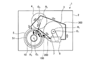
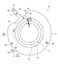
図1は、第1実施形態における動力伝達装置の油路構造を説明するための模式図である。なお、図1には、説明の便宜上、実施形態には含まれない油路(従来の供給パイプ300、最短経路の油路200)が図示されている。
[First Embodiment]
[1. overall structure]
[1−1.動力伝達装置]
動力伝達装置1は、ケース2に収容された状態で車両に搭載され、エンジンから出力された動力を駆動輪に伝達する機構である。図1に示す動力伝達装置1は、フロントエンジン・フロントドライブ式の車両(FF車)に搭載されるものであり、ケース2に収容された変速機3、カウンタギヤ機構4、およびデファレンシャルギヤ機構5を備える。つまり、ケース2は、変速機3およびデファレンシャルギヤ機構5を収容するトランスアクスルケース(T/Aケース)である。この動力伝達装置1では、エンジンから駆動輪に至る動力伝達経路上で、変速機3からカウンタギヤ機構4を介してデファレンシャルギヤ機構5へ動力を伝達する。
[1-1. Power transmission device]
The
詳細には、動力伝達装置1は複数の回転軸を有する。ケース2の内部には、動力伝達装置1を構成する第1軸R1、第2軸R2、および第3軸R3が設けられている。変速機3は、エンジンと同一軸線上の第1軸R1上に設けられ、第1軸線O1を回転中心とする入力軸および出力ギヤを備えている。例えば、変速機3は遊星歯車機構により構成されている。カウンタギヤ機構4は、第2軸R2上に設けられている。デファレンシャルギヤ機構5は、第3軸R3上に設けられ、駆動軸を介して左右の駆動輪(前輪)が接続されている。すなわち、第1軸R1には変速機3の入力軸、第2軸R2にはカウンタギヤ機構4のカウンタシャフト41(図3に示す)、第3軸R3には駆動軸が含まれる。この説明では、第1軸R1の軸芯を第1軸線O1、第2軸R2の軸芯を第2軸線O2、第3軸R3の軸芯を第3軸線O3と記載する。
Specifically, the
また、ケース2の内部には、第3軸線O3の周りに、オイルの流動方向を規制するバッフルプレート10と、デファレンシャルギヤ機構5のデフケース51とが設けられている。バッフルプレート10は、オイル供給先であるデファレンシャルギヤ機構5の周辺で、デフケース51の外側に配置されている。なお、バッフルプレート10の詳細な構造は後述する。
In addition, a
さらに、ケース2の内部には、オイル供給源として、エンジンによって駆動する機械式オイルポンプ6が設けられている。機械式オイルポンプ6は、第1軸R1とは別軸上に配置されており、チェーン機構などの伝動装置7を介して第1軸R1のトルクを伝達可能に接続されている。なお、第1軸線O1と同一線上に機械式オイルポンプ6が設けられてもよい。
Further, a
[1−2.油路構造]
ここで、実施形態の油路構造と従来構造とを比較する。まず、従来構造の供給パイプ300は、機械式オイルポンプ6からデファレンシャルギヤ機構5へオイルを供給するために、デフケース51の外側を迂回するように配管されている。また、デファレンシャルギヤ機構5は第3軸R3上に設けられているため、供給パイプ300は第1軸R1および第2軸R2の外側を迂回してケース2の壁面に沿うようにして第3軸R3周辺まで延びている。そのため、従来の供給パイプ300では油路長が長くなり、油路長によるオイルの圧力損失が大きくなってしまう。そこで、油路長を短くするために最短経路の油路(以下「最短油路」という)200を形成することが考えられる。
[1-2. Oil passage structure]
Here, the oil passage structure of the embodiment is compared with the conventional structure. First, the
最短油路200は、機械式オイルポンプ6からデファレンシャルギヤ機構5に向けて全体が直線的な経路となる。しかしながら、オイル供給先の周辺には軸受や補強用のリブなど多くの要素(周辺部材)が存在して構造が複雑である。そのため、オイル供給先にオイルを供給できる位置に排出口を設けて、その排出口の位置と機械式オイルポンプ6とを繋ぐように直線の油路を接続して最短油路200を実現することは困難である。そこで、周辺部材を避けるように直線の油路を接続することが考えられるが、この場合には油路を急に曲げた直角カーブとなることで、油路形状によるオイルの圧力損失が大きくなってしまう。そこで、本実施形態の供給油路100は、オイル供給先の周辺に曲線的な油路を設けて油路形状によるオイルの圧力損失を低減するとともに、従来の供給パイプ300よりも最短油路200に近い経路を実現して油路長による圧力損失を低減するように構成されている。
The
実施形態の供給油路100は、機械式オイルポンプ6から円筒状のバッフルプレート10を介してデファレンシャルギヤ機構5へオイルが圧送されるように構成されている。バッフルプレート10は、プレート内に周方向に沿って延びる油路が形成された油路付きバッフルプレートである。また、バッフルプレート10はオイル供給先の周辺に配置されている。そのため、供給油路100では、オイル供給先の周辺においてバッフルプレート10内を周方向に沿って延びている油路を用いてオイルを圧送させることが可能である。つまり、オイル供給先の周辺部材であるバッフルプレート10によってオイル供給先の周辺を周方向に沿って延びる油路が構成される。これにより、油路形状によるオイルの圧力損失を低減することができる。また、供給油路100は、従来の供給パイプ300よりも最短油路200に近い経路となる。図1に示すように、軸線方向からみた場合に、供給パイプ300は複数の回転軸(第1軸R1、第2軸R2、第3軸R3)の外側に設けられているが、供給油路100は、複数の回転軸の内側すなわちオイル供給源側の第1軸R1とオイル供給先側の第3軸R3との間(さらに、第2軸R2と第3軸R3との間)を通るように設けられているため、供給パイプ300よりも油路長が短くなる。これにより、油路長によるオイルの圧力損失を低減することができる。
The
[2.バッフルプレートの配置およびオイル供給先]
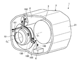
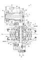
図2,図3を参照して、バッフルプレート10の配置およびオイル供給先について説明する。図2は、バッフルプレート10の配置を説明するための模式図である。図3は、ケース2の内部構造を模式的に示す断面図である。なお、図2には、デファレンシャルギヤ機構5を示さず、ケース2は一部が示されている。
[2. Baffle plate arrangement and oil supply destination]
The arrangement of the
[2−1.バッフルプレートの配置]
バッフルプレート10は、ケース2の内部で第3軸線O3の周りに配置され、その軸線方向に所定長さを有する筒状に形成されている。また、図3に示すように、バッフルプレート10は、ケース2の内壁に取り付けられる固定部材であり、デフケース51とケース2との間に配置されている。そのデフケース51を備えているデファレンシャルギヤ機構5はオイル供給先である。つまり、バッフルプレート10はオイル供給先の周辺でケース2の内壁に取り付けられている。
[2-1. Arrangement of baffle plate]
The
ケース2は、変速機3を収容する筒状のケース本体21と、ケース本体21の両側の開口部に取り付けられる二つのカバー部材とを備えている。図3に示すように、ケース本体21とカバー部材22とはボルト締めされて一体化されている。図3に示す例では、カバー部材22は軸線方向でエンジン側に配置されたフロントカバーであり、バッフルプレート10はカバー部材22の内壁にボルト締結されている。なお、ケース本体21とカバー部材22とを特に区別しない場合にはケース2と記載する。
The
[2−2.オイル供給先]
図2に破線で示すように、供給油路100は、エンジンによって駆動する機械式オイルポンプ6からバッフルプレート10を介してオイル供給先へオイルが圧送される経路に構成されている。詳細には、供給油路100は、バッフルプレート10の内部を貫通し第3軸線O3の周方向に沿って延びているプレート油路130と、ケース2に形成された油路であるケース油路140とを含む。すなわち、供給油路100の一部がバッフルプレート10に設けられている。ケース油路140は、機械式オイルポンプ6とプレート油路130との間で供給油路100を構成する。下流側のプレート油路130と上流側のケース油路140とは連通しており、機械式オイルポンプ6からオイル供給先へオイルを圧送することができる。さらに、バッフルプレート10には、ケース油路140からオイルが供給される供給口150と、第3軸線O3上のオイル供給先である第1供給先Aへオイルを排出する第1排出口161と、第2軸線O2上のオイル供給先である第2供給先Bへオイルを排出する第2排出口162とが形成されている。
[2-2. Oil supply destination]
As shown by a broken line in FIG. 2, the
供給口150は、ケース油路140に接続される接続口であり、プレート油路130と連通している。また、供給口150と第1排出口161と第2排出口162とはいずれもバッフルプレート10の周方向で異なる位置に設けられている。そして、プレート油路130は、供給口150と第1排出口161とに連通し、かつ供給口150と第2排出口162とに連通する。これにより、供給口150からプレート油路130内(バッフルプレート10内)に流入したオイルは、プレート油路130内を周方向に流動し、第1排出口161および第2排出口162から異なるオイル供給先(第1供給先Aおよび第2供給先B)へ排出される。つまり、供給油路100は、バッフルプレート10を介して異なる軸上に配置された複数のオイル供給先へオイルを供給することができる。
The
図3に示すように、供給油路100のオイル供給先は、バッフルプレート10と同軸上においてデフケース51を支持するデフ軸受55(第1供給先A)と、バッフルプレート10と別軸上に配置されたカウンタギヤ機構4(第2供給先B)と、バッフルプレート10と同軸上においてデフケース51の内側に設けられたデフピニオンギヤ53およびデフサイドギヤ54(後述する図5、図8に示す第3供給先C)とを含む。
As shown in FIG. 3, the oil supply destination of the
詳細には、デファレンシャルギヤ機構5は、デフケース51と、そのデフケース51と一体回転するデフリングギヤ52と、デフケース51の内側に設けられたデフピニオンギヤ53およびデフサイドギヤ54とを備えている。デフピニオンギヤ53とデフサイドギヤ54との噛み合い部は、供給油路100の第3供給先Cとなる潤滑必要部位である。デフケース51は、軸線方向の両端側に設けられたボス部51a,51bを有し、転がり軸受であるデフ軸受55を介してケース2に回転自在に支持されている。デフ軸受55は、一方のボス部51aの外周部に取り付けられている第1デフ軸受55Aと、他方のボス部51bの外周部に取り付けられている第2デフ軸受55Bとを含む。第1デフ軸受55Aは、供給油路100の第1供給先Aとなる潤滑必要部位であり、デフケース51の外側に位置する。図3に示す例では、第1デフ軸受55Aはバッフルプレート10の小径側の開口部に近い位置に設けられている。
Specifically, the
カウンタギヤ機構4は、第2軸線O2上に配置された中空状のカウンタシャフト41と、そのカウンタシャフト41と一体回転するカウンタドリブンギヤ42およびカウンタドライブギヤ43とを備えている。カウンタシャフト41は、転がり軸受であるカウンタ軸受44を介してケース2に回転自在に支持されている。カウンタ軸受44は、供給油路100の第2供給先Bとなる潤滑必要部位、すなわち別軸上(第2軸R2側)の潤滑必要部位に含まれる。カウンタドリブンギヤ42は、変速機3の出力ギヤ(図示せず)と噛み合っている。カウンタドライブギヤ43は、デフリングギヤ52と噛み合っている。これらのギヤ噛み合い部も第2軸R2側の潤滑必要部位に含まれる。図3に示す例では、バッフルプレート10の第2排出口162は、カウンタシャフト41の内部に向けて開口し、第2供給先Bのカウンタギヤ機構4にオイルを供給する。
The
[3.バッフルプレートの構造]
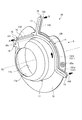
図4,5を参照して、バッフルプレート10の構造を詳細に説明する。図4は、第1実施形態のバッフルプレート10を模式的に示す斜視図である。図5は、図4のS方向からみた場合を模式的に示す平面図である。なお、ここでは「第3軸線O3の軸線方向」を単に「軸線方向」と記載し、第3軸線O3を基準にして径方向および周方向と記載する。
[3. Baffle plate structure]
The structure of the
バッフルプレート10は、樹脂により構成された板状部材であり、インジェクション成形によって全体が一体成形されている。そのインジェクション成形時に、バッフルプレート10の内部にプレート油路130が形成される。
The
インジェクション成形では、溶融した樹脂を金型内の空間(キャビティ)に充填し、そのキャビティ内の樹脂が冷却されることにより固化する。その際、金型の温度は溶融樹脂の温度よりも低いので、溶融樹脂は金型に接触する部分(表面)から温度低下して固化し始める。つまり、バッフルプレート10のインジェクション成形時、一時的に、キャビティ内の樹脂は、金型に接触する部分が固化して表面固化層を形成するものの、表面固化層の内側(金型に接していない内側部分)が固化していない状態となる。この状態において、表面固化層の内側で固化していない樹脂の内部に気体(例えば空気、ガス)や水などを送り込み、表面固化層に囲まれた溶融樹脂を金型の外部に取り除く。その結果、表面固化層に囲まれた空洞が樹脂の内部に形成される。その空洞がプレート油路130となる。この方法によって、バッフルプレート10の内部にプレート油路130が形成される。
In injection molding, molten resin is filled into a space (cavity) in a mold, and the resin in the cavity is solidified by cooling. At that time, since the temperature of the mold is lower than the temperature of the molten resin, the molten resin starts to solidify as the temperature decreases from the portion (surface) that contacts the mold. That is, at the time of injection molding of the
プレート油路130は、供給口150に連通する第1油路131と、第1排出口161に連通する第2油路132と、第2排出口162に連通する第3油路133とを含む。第1油路131は、上流側の導入油路131aと、下流側のメイン油路131bとを含む。また、プレート油路130は上流側から下流側に向けて第1油路131が第2油路132と第3油路133とに分岐している。
The
図4,5に示すように、バッフルプレート10には、筒状部11と、フランジ部12と、供給部13と、第1油路形成部14と、第2油路形成部15と、第1排出部16と、第3油路形成部17と、第2排出部18と、固定部19とが形成されている。
As shown in FIGS. 4 and 5, the
筒状部11は、高さ方向(軸線方向)の両側が開口したドーム状に形成されている。筒状部11には、ドーム状における頂部側に開口する第1開口部11aと、ドーム状における底部側に開口する第2開口部11bとが設けられている。各開口部11a,11bはいずれも円形状に形成されており、第1開口部11aは第2開口部11bよりも小径である。つまり、筒状部11は、ドーム状における底部側の第2開口部11bからドーム状における頂部側の第1開口部11aに向けて複数段あるいは徐々に縮径している。ケース2にバッフルプレート10を取り付けた状態で、筒状部11はケース2と潤滑必要部位(例えばデファレンシャルギヤ機構5)との間でオイルの流れを規制する隔壁として機能する。
The
フランジ部12は、ケース2に取り付けられる固定部であって、バッフルプレート10の位置決め部である。図4,5に示すように、フランジ部12は、第2開口部11bから径方向外側に突出しているとともに、周方向に沿って延びている。また、フランジ部12には、周方向に所定間隔を空けた位置に第1ボルト孔20aおよび第2ボルト孔20bが設けられている。各ボルト孔20a,20bには、バッフルプレート10をケース2に固定するためのボルトが螺合する。
The
供給部13は、供給口150が開口している部分である。図4に示すように、供給部13は、フランジ部12から径方向外側に突出している平板部であり、その内部が中空に形成されている。供給部13の高さ(軸線方向長さ)はフランジ部12の板厚よりも長い。図5に示すように、供給口150は、供給部13のうち軸線方向で他方向側の面に開口している。また、供給口150が開口している方向は、第1排出口161が開口している方向に対して軸線方向で反対方向、かつ第2排出口162が開口している方向とは軸線方向で同一方向である。バッフルプレート10をケース2に取り付けた場合、供給部13はケース2に接続されてケース油路140と連通する。
The
第1油路形成部14は、第1油路131を形成する部分である。図4,5に示すように、第1油路形成部14は、筒状部11の底部側で周方向に延びているメイン部分と、そのメイン部分の端部から径方向外側に延びている導入部分とを含む。その導入部分の先端側(径方向外側)に供給部13が設けられている。
The first oil
第2油路形成部15は、第2油路132を形成する部分である。図4に示すように、第2油路形成部15は、第1油路形成部14と一連に形成された筒状の突出部であり、フランジ部12から第1開口部11a側に向けて軸線方向に突出している。第2油路形成部15の内部空間が第2油路132を構成している。そして、第2油路形成部15の先端部に第1排出部16が設けられている。
The second oil
第1排出部16は、第1排出口161が開口している部分である。図4に示すように、第1排出口161は、第2油路形成部15の先端部に設けられ、軸線方向で一方向側に向けて開口している。すなわち、第1排出部16は、第2油路形成部15の先端部である。バッフルプレート10をケース2に取り付けた場合、第1排出口161は第1供給先Aにオイルを供給する位置に配置される。
The
第3油路形成部17は、第3油路133を形成する部分である。図4,5に示すように、第3油路形成部17は、直線状の平板部であり、第1油路形成部14から径方向外側に延びている。また、第3油路形成部17の内部は中空に形成されている。第3油路形成部17の内部空間が第3油路133を構成している。そして、第3油路形成部17の先端側(径方向外側)に第2排出部18が設けられている。
The third oil
第2排出部18は、第2排出口162が開口している部分である。図5に示すように、第2排出部18は、第3油路形成部17のうち先端側(径方向外側)の部分により構成されている。第2排出口162は、第3油路形成部17のうち軸線方向で他方向側の面に開口している。また、第2排出口162が開口している方向は、軸線方向の他方向側、すなわち第1排出口161とは軸線方向で反対方向である。ケース2にバッフルプレート10を取り付けた場合、第2排出口162は第2供給先Bにオイルを供給する位置に配置される。例えば、第2排出口162がカウンタシャフト41の内部に向けて開口するように第2排出部18が配置される。
The
固定部19は、ケース2にボルト締結される部分である。図4に示すように、固定部19は、第2油路形成部15と並んで突出している形状を有し、その先端部に第3ボルト孔20cが設けられている。第3ボルト孔20cには、バッフルプレート10をケース2に固定するためのボルトが螺合する。
The fixing
さらに、図5に示す破線で示すように、バッフルプレート10には、第2油路132から筒状部11の内側に向けて開口する貫通孔163が形成されている。貫通孔163は、プレート油路130内のオイルを排出し、第3供給先Cであるデフピニオンギヤ53およびデフサイドギヤ54へオイルを供給する排出口(第3排出口)として機能する。すなわち、プレート油路130は、供給口150から第1排出口161に至る油路と、供給口150から第2排出口162に至る油路と、供給口150から貫通孔163に至る油路とに分岐している。
Furthermore, as shown by the broken line shown in FIG. 5, the
なお、供給部13および第2排出部18の形状は、上述した平板部に限定されない。例えば、供給部13と第2排出部18とは、いずれも軸線方向に沿って延びる有底円筒状に形成されてもよい。この場合、供給部13は、第2開口部11bよりも軸線方向外側に突出している先端部を有し、その先端部に供給口150が開口している。また、第2排出部18は、第2開口部11bよりも軸線方向外側に突出している先端部を有し、その先端部に第2排出口162が開口している。その供給部13の先端部と第2排出部18の先端部とは、軸線方向で同一方向に突出している。
In addition, the shape of the
[4.オイルの流れ]
ここで、プレート油路130によるオイルの流れについて説明する。供給口150からプレート油路130内に流入したオイルは、第1油路131の導入油路131a内を径方向内側に向けて流れる。そして、導入油路131aからメイン油路131b内に流入したオイルは、バッフルプレート10の周方向に沿って流れる。バッフルプレート10はオイル供給先の周辺でケース2の内壁に取り付けられているため、第1油路131内を流れるオイルはオイル供給先の周辺で周方向に沿って流れることになる。さらに、メイン油路131b内を流れるオイルは、第1油路131と第3油路133との分岐箇所において、第2油路132側と第3油路133側とに分岐して流れる。
[4. Oil flow]
Here, the flow of oil through the
その分岐箇所から第2油路132側に流れたオイルは、第1油路131から第2油路132へ流入する。そして、第2油路132内に流入したオイルは、第1排出口161から排出され、もしくは第3排出口である貫通孔163から排出される。一方、その分岐箇所から第3油路133側に流れたオイルは、第3油路133内を径方向外側に向けて流れ、第2排出口162から排出される。
The oil that has flowed from the branch point toward the
そして、第1排出口161から排出されたオイルは、バッフルプレート10の外側に位置する第1供給先Aの第1デフ軸受55Aに向けて流れる。第2排出口162から排出されたオイルは、別軸上に位置する第2供給先Bのカウンタギヤ機構4に含まれるカウンタシャフト41の内部に流入する。この第1排出口161と第2排出口162とは軸線方向で反対側に向けて開口しているので、プレート油路130はオイルを軸線方向で異なる方向に排出することができる。また、第3排出口の貫通孔163から排出されたオイルは、筒状部11の内側に位置する第3供給先Cのデフピニオンギヤ53およびデフサイドギヤ54に向けて流れる。
Then, the oil discharged from the
このように、バッフルプレート10に複数のオイル供給先に共通するプレート油路130を設け、第1排出口161と第2排出口162と第3排出口である貫通孔163とを異なる潤滑必要部位ごとに設けることで、隣接し潤滑油が不足する潤滑必要部位に潤滑油を供給できる。これにより、潤滑必要部位での潤滑油不足を補いつつ、油路の数を減らすことができる。そのため、動力伝達装置1の製造コストを抑制できる。
In this way, the
以上説明した通り、第1実施形態の油路構造では、オイル供給先の周辺でケース2の内壁に取り付けられるバッフルプレート10に、供給油路100の一部を構成するプレート油路130が形成されている。プレート油路130は、オイル供給先の周辺で周方向に延びているとともに、オイル供給先にオイルを供給する複数の排出口161,162に連通している。そのため、オイル供給先の周辺において周方向に延びているプレート油路130を用いてオイル供給先へオイルを圧送することができる。これにより、油路形状によるオイルの圧力損失を低減することができる。また、供給油路100の油路長を短くすることが可能になり、油路長によるオイルの圧力損失を低減することもできる。そして、供給油路100における圧力損失が低減されることにより、機械式オイルポンプ6の負荷を低減することができる。さらに、ケース2の内部に配置される供給パイプを削減できるため、部品点数を削減できるとともに、製造コストを削減できる。加えて、ケース2を軽量化すなわち動力伝達装置1を軽量化できる。これにより、動力伝達装置1を搭載する車両の燃費を向上させることができる。
As described above, in the oil passage structure of the first embodiment, the
加えて、第1実施形態のバッフルプレート10は、インジェクション成形によって全体が一体成形されている。そのインジェクション成形時に、バッフルプレート10の内部にプレート油路130を形成することができる。これにより、複数の部材を組み合わせて一体化されたバッフルプレートを製造する場合に比べて部品点数を削減でき、製造コストを削減できる。
In addition, the
[第1実施形態の変形例]
第1実施形態の変形例として、バッフルプレート10には独立したプレート油路が複数設けられてもよい。その変形例の一例として、独立した二つのプレート油路が設けられたバッフルプレート10を図6に示す。なお、この変形例の説明では、上述した第1実施形態と同様の構成については説明を省略し、その参照符号を引用する。
[Modification of First Embodiment]
As a modification of the first embodiment, the
図6は、第1実施形態の変形例におけるプレート油路を説明するための平面図である。図6に示すように、変形例のバッフルプレート10には、プレート油路130とは別に第2プレート油路170が設けられている。さらに、バッフルプレート10には、第2供給口171と、第4排出口172とが形成されている。第2プレート油路170には第2供給口171から供給されたオイルが流入し、第4排出口172からオイルが排出される。第2プレート油路170は、フランジ部12のうちプレート油路130が設けられていない部分に形成されており、フランジ部12の周方向に沿って延びている。第4排出口172は、第4供給先Dにオイルを供給する位置に設けられている。そして、プレート油路130のオイル供給先(第1供給先A、第2供給先B、第3供給先C)と、第2プレート油路170のオイル供給先(第4供給先D)とは、潤滑必要部位と油圧式アクチュエータのどちらであってもよい。例えば、プレート油路130を介して潤滑必要部位(第1供給先A、第2供給先B、第3供給先C)にオイルを供給し、第2プレート油路170を介して油圧式アクチュエータ(第4供給先D)に油圧を供給することができる。デフケース51の近くに配置されたバッフルプレート10において、二つのプレート油路130,170それぞれにオイルを流すことにより、異なる油圧のオイルを異なるオイル供給先に供給できる。なお、図6に示す第4排出口172から第4供給先Dに至る矢印は、第4排出口172からオイルが排出される方向、すなわち第4供給先Dの位置を示すものではなく、第4排出口172から排出されたオイルの供給先を特定するためのものである。
FIG. 6 is a plan view for explaining a plate oil passage in a modification of the first embodiment. As shown in FIG. 6, the modified
[第2実施形態]
[5.第2実施形態におけるバッフルプレートの構造]
次に、図7を参照して、第2実施形態における動力伝達装置の油路構造について説明する。第2実施形態では、第1実施形態とは異なり、別々に成形された部材を一体化させることによりバッフルプレート10が形成されている。なお、この説明では、上述した第1実施形態と同様の構成については説明を省略し、その参照符号を引用する。
[Second Embodiment]
[5. Structure of baffle plate in the second embodiment]
Next, the oil passage structure of the power transmission device in the second embodiment will be described with reference to FIG. In the second embodiment, unlike the first embodiment, the
図7は、第2実施形態におけるバッフルプレート10を模式的に示す斜視図である。図7に示すように、第2実施形態のバッフルプレート10は、プレート本体110と、管状部材120とを一体化させた構造を有する。
FIG. 7 is a perspective view schematically showing the
[5−1.プレート本体]
プレート本体110は、樹脂により構成された板状部材であり、バッフルプレート10の主体を構成する部材(第1部材)である。例えば、プレート本体110はインジェクション成形によって全体が一体成形されている。そのプレート本体110には、筒状部11と、フランジ部12と、固定部19と、供給部111と、支持部112とが形成されている。
[5-1. Plate body]
The plate body 110 is a plate-like member made of resin, and is a member (first member) that constitutes the main body of the
供給部111は、供給口150が開口している部分である。図7に示すように、供給部111は、フランジ部12の外周部に設けられた有底円筒状の中空部であり、軸線方向においてフランジ部12の両側に突出している。供給口150は供給部111のうち軸線方向で一方端側の面に開口している(図7には示さず)。例えば、供給口150の径方向位置はフランジ部12の外周部よりも径方向外側である。さらに、供給部111の側面部には管状部材120が接続されている。これにより、供給口150と管状部材120の内部空間とが連通される。
The
支持部112は、管状部材120を支持する部分である。支持部112はプレート油路130内のオイルが所望の位置(オイル供給先)に向けて排出されるように管状部材120を支持する。図7に示すように、支持部112は、筒状部11の外側に設けられた平板部であり、径方向および軸線方向に延びている。軸線方向において、支持部112の先端部は第1開口部11aよりも外側に突出している。つまり、支持部112の側面は、筒状部11から軸線方向に突出しているとともに、第1開口部11aよりも軸線方向外側では、径方向に延びている。その支持部112の先端部に管状部材120の第1排出部が一体化されている。
The
[5−2.管状部材]
管状部材120は、樹脂により構成された管状部材であり、プレート油路130を構成する部材(第2部材)である。図7に示すように、管状部材120は、全体が細長い管状に繋がった形状を有し、プレート本体110の外表面に一体化(固定)されている。例えば、溶着や接着などにより管状部材120がプレート本体110に一体化されている。これにより、バッフルプレート10にはプレート油路130が一体的に形成される。すなわち、管状部材120はバッフルプレート10の一部であるため、第2実施形態のプレート油路130はバッフルプレート10の内部を貫通している油路といえる。詳細には、第2実施形態のプレート油路130は、プレート本体110の内部を貫通する油路ではなく、バッフルプレート10の一部を構成する管状部材120によって形成される油路である。その管状部材120は、第1油路形成部121と、第2油路形成部122と、第3油路形成部123とを含む。
[5-2. Tubular member]
The
第1油路形成部121は、第1油路131を構成する管部分であり、フランジ部12の外表面に一体化されている。図7に示すように、第1油路形成部121は、供給部111から径方向内側に向けて延びている導入部分と、筒状部11の底部側で周方向に沿って延びているメイン部分とを含む。第1油路形成部121の下流側部分は、第2油路形成部122と連通している。
The first oil
第2油路形成部122は、第2油路132を構成する管部分であり、筒状部11の外表面および支持部112の側面に一体化されている。図7に示すように、第2油路形成部122の上流側部分は、筒状部11の外表面に一体化されている部分であり、筒状部11の底部側から頂部側(軸線方向で第2開口部11b側から第1開口部11a側)に向けて延びている。第2油路形成部122の下流側部分は、支持部112の側面に一体化されている部分であり、第1開口部11aよりも軸線方向外側に延びているとともに径方向内側に向けて延びている。そして、第2油路形成部122は、径方向内側を向く下流側先端部122aを有する。下流側先端部122aには、第1排出口161が開口している。第1排出口161は径方向内側に向けて開口している。そのため、第2油路132内を流れたオイルは、第1排出口161から径方向内側に向けて排出される。これにより、第1排出口161から第1供給先Aに直接オイルを供給することができる。
The second oil
第3油路形成部123は、第3油路133を構成する管部分であり、第2油路形成部122から径方向外側に向けて延びている。第3油路形成部123の上流側の端部は、第2油路形成部122の上流側部分と一体化されている。これにより、第2油路132と第3油路133とが連通される。また、第3油路形成部123の下流側部分は、径方向から軸線方向に曲がった形状を有し、軸線方向に向けて延びている。つまり、第3油路形成部123は、軸線方向を向く下流側先端部123aを有する。下流側先端部123aには、第2排出口162が開口している。なお、下流側先端部123aが延びている方向は、供給部111の供給口150が開口している方向と軸線方向で同一方向である。
The third oil
以上説明した通り、第2実施形態の油路構造では、管状部材120によってプレート油路130が構成されているので、プレート油路130の流路断面が円形状となる。これにより、プレート油路130内をオイルが流動する際にオイルの圧力損失を低減することができる。また、プレート本体110に管状部材120を一体化するため、従来の供給パイプを設置するためのスペースを削減できる。さらに、第1実施形態とは異なる製造方法によって油路付きのバッフルプレート10を形成できる。
As described above, in the oil passage structure of the second embodiment, since the
[第2実施形態の変形例]
第2実施形態のバッフルプレート10は、プレート本体110と管状部材120とは、両方が樹脂により構成される場合に限らず、少なくとも一方の部材が樹脂により構成されてもよい。例えば、プレート本体110が金属製であり、管状部材120が樹脂製であってもよい。あるいは、プレート本体110が樹脂製であり、管状部材120が金属製であってもよい。このように、プレート本体110と管状部材120とのうちいずれか一方が金属製、他方が樹脂製の場合でも、プレート本体110と管状部材120とを一体化させることが可能である。
[Modification of Second Embodiment]
In the
なお、本発明は上述した実施形態に限定されず、本発明の目的を逸脱しない範囲で適宜変更が可能である。 In addition, this invention is not limited to embodiment mentioned above, In the range which does not deviate from the objective of this invention, it can change suitably.
上述したバッフルプレート10の配置は、第3軸線O3上において、ケース2とデフケース51との間に設けられる場合に限定されない。図示しないが、バッフルプレート10はカウンタシャフト41が設けられている第2軸線O2上(第2軸R2上)に設けられてもよい。
The arrangement of the
さらに、動力伝達装置1は、上述したFF車に搭載される場合に限定されず、リヤエンジン・リヤドライブ式の車両(RR車)に搭載されてもよい。さらに、上述した油路構造は、リヤ側にエンジンとは別の動力源(例えば電動モータ)およびカウンタギヤ機構が設けられている動力伝達装置を対象とすることができる。このリヤドライブ式の車両に適用される場合、第1排出口161はリヤ側のデファレンシャルギヤ機構にオイルを供給し、第2排出口162はリヤ側のカウンタギヤ機構にオイルを供給する。あるいは、上述した油路構造は、フロントエンジン・リヤドライブ式の車両(FR車)に搭載される動力伝達装置を対象とすることができる。FR車に適用される場合、バッフルプレート10は、リヤ側のデファレンシャルギヤ機構を覆うように配置される。そして、第1排出口161からリヤ側のデフ軸受にオイルを供給し、貫通孔163からリヤ側のデフピニオンギヤおよびデフサイドギヤにオイルを供給する。
Furthermore, the
また、供給油路100においてバッフルプレート10を介するオイル供給先は、潤滑必要部位に限定されず、動力伝達装置1に設けられている油圧式アクチュエータ(図示せず)であってもよい。つまり、バッフルプレート10のプレート油路130を介して油圧式アクチュエータにオイル(油圧)を供給することができる。例えば、動力伝達装置1のクラッチやブレーキに設けられた油圧式アクチュエータをオイル供給先とする。
Further, the oil supply destination via the
さらに、プレート油路130における複数のオイル供給先は、全てが潤滑必要部位となる場合に限定されない。つまり、プレート油路130を介するオイル供給先には、潤滑必要部位と油圧式アクチュエータとが両方含まれてもよい。例えば、プレート油路130内を圧送されるオイルは、第1排出口161から第1供給先Aである潤滑必要部位に供給され、第2排出口162から第2供給先Bである油圧式アクチュエータに供給される。すなわち、第1排出口161と第2排出口162とは、いずれか一方が潤滑必要部位にオイルを供給する位置に設けられ、他方が油圧式アクチュエータにオイルを供給する位置に設けられている。
Further, the plurality of oil supply destinations in the
また、オイル供給源は、オイルポンプであればよく、機械式オイルポンプ6に限定されず、電動オイルポンプであってもよい。さらに、電動オイルポンプの配置も特に限定されない。
The oil supply source may be an oil pump and is not limited to the
1 動力伝達装置
2 ケース
3 変速機
4 カウンタギヤ機構
5 デファレンシャルギヤ機構
10 バッフルプレート
100 供給油路
130 プレート油路
131 第1油路
132 第2油路
133 第3油路
140 ケース油路
150 供給口
161 第1排出口
162 第2排出口
A 第1供給先
B 第2供給先
C 第3供給先
DESCRIPTION OF
Claims (8)
前記オイルポンプから前記バッフルプレートを介してオイル供給先にオイルが圧送される供給油路、を備え、
前記バッフルプレートには、
前記供給油路の一部を構成し、周方向または径方向に延びる油路であるプレート油路と、
前記オイルポンプから吐出されたオイルを前記プレート油路内に流入させる供給口と、
前記オイル供給先に供給されるオイルを前記プレート油路から排出する排出口とが形成されている
ことを特徴とする動力伝達装置の油路構造。 In the oil passage structure of the power transmission device comprising a case for housing the power transmission device, a baffle plate attached to the inner wall of the case, and an oil pump,
A supply oil passage through which oil is pumped from the oil pump to the oil supply destination via the baffle plate,
In the baffle plate,
A plate oil passage that constitutes a part of the supply oil passage and that extends in the circumferential direction or the radial direction ;
A supply port through which oil discharged from the oil pump flows into the plate oil passage;
An oil passage structure for a power transmission device, wherein an outlet for discharging oil supplied to the oil supply destination from the plate oil passage is formed.
前記オイルポンプから前記バッフルプレートを介してオイル供給先にオイルが圧送される供給油路、を備え、
前記バッフルプレートには、
前記供給油路の一部を構成する油路であるプレート油路と、
前記オイルポンプから吐出されたオイルを前記プレート油路内に流入させる供給口と、
前記オイル供給先に供給されるオイルを前記プレート油路から排出する排出口とが形成されており、
前記オイル供給先は、前記ケースの内部で異なる位置にある第1供給先と第2供給先とを含み、
前記排出口は、
前記第1供給先に供給されるオイルを排出する第1排出口と、
前記第2供給先に供給されるオイルを排出する第2排出口とを含み、
前記プレート油路は、前記供給口から前記第1排出口に至る油路と前記供給口から前記第2排出口に至る油路とに分岐している
ことを特徴とする動力伝達装置の油路構造。 In the oil passage structure of the power transmission device comprising a case for housing the power transmission device, a baffle plate attached to the inner wall of the case, and an oil pump,
A supply oil passage through which oil is pumped from the oil pump to the oil supply destination via the baffle plate,
In the baffle plate,
A plate oil passage which is an oil passage constituting a part of the supply oil passage;
A supply port through which oil discharged from the oil pump flows into the plate oil passage;
A discharge port for discharging the oil supplied to the oil supply destination from the plate oil passage is formed;
Before Symbol oil supply destination includes a first supply destination and a second supply destination on the inside at different positions of the case,
The outlet is
A first outlet for discharging oil supplied to the first supply destination;
A second outlet for discharging the oil supplied to the second supply destination,
The plate oil passage, the kinematic coupling device you said that branches into the oil passage leading to the second outlet oil path leading to the first outlet from said supply port and from said supply port Oil passage structure.
前記第1供給先は、前記動力伝達装置に含まれるデファレンシャルギヤ機構の構成要素であり、
前記第2供給先は、前記動力伝達装置のうち前記デファレンシャルギヤ機構とは別の構成要素であり、
前記第1排出口は、前記第1供給先にオイルを直接供給する位置に設けられ、
前記第2排出口は、前記第2供給先にオイルを直接供給する位置に設けられている
ことを特徴とする請求項2に記載の動力伝達装置の油路構造。 The plate oil passage is an oil passage that supplies the oil to a lubrication-needed portion that requires lubrication with oil in the power transmission device,
The first supply destination is a component of a differential gear mechanism included in the power transmission device,
The second supply destination is a component different from the differential gear mechanism in the power transmission device,
The first discharge port is provided at a position where oil is directly supplied to the first supply destination,
The oil passage structure of the power transmission device according to claim 2, wherein the second discharge port is provided at a position where oil is directly supplied to the second supply destination.
前記排出口は、前記第3供給先にオイルを直接供給する位置に設けられた第3排出口をさらに含み、
前記プレート油路は、前記供給口から前記第1排出口に至る油路と前記供給口から前記第3排出口に至る油路とに分岐しており、
前記第1供給先は、前記デフピニオンギヤおよび前記デフサイドギヤを収容するデフケースを前記ケースに支持するデフ軸受であり、
前記バッフルプレートは、前記デフケースを覆うように配置されている
ことを特徴とする請求項3に記載の動力伝達装置の油路構造。 The oil supply destination further includes a third supply destination that is a differential pinion gear and a differential side gear constituting the differential gear mechanism,
The discharge port further includes a third discharge port provided at a position where oil is directly supplied to the third supply destination,
The plate oil passage is branched into an oil passage from the supply port to the first discharge port and an oil passage from the supply port to the third discharge port,
The first supply destination is a differential bearing that supports a differential case that houses the differential pinion gear and the differential side gear on the case;
The oil passage structure of the power transmission device according to claim 3, wherein the baffle plate is disposed so as to cover the differential case.
前記バッフルプレートは、前記デファレンシャルギヤ機構が配置されている軸線上に設けられ、
前記第1供給先は、前記デファレンシャルギヤ機構の構成要素であり、
前記第2供給先は、前記油圧式アクチュエータであり、
前記第1排出口は、前記第1供給先にオイルを直接供給する位置に設けられている
ことを特徴とする請求項2に記載の動力伝達装置の油路構造。 The plate oil passage is a lubricating oil passage for supplying oil to components of a differential gear mechanism included in the power transmission device, and an oil passage for supplying oil pressure to a hydraulic actuator included in the power transmission device. ,
The baffle plate is provided on an axis on which the differential gear mechanism is disposed,
The first supply destination is a component of the differential gear mechanism,
The second supply destination is the hydraulic actuator,
The oil passage structure of a power transmission device according to claim 2, wherein the first discharge port is provided at a position where oil is directly supplied to the first supply destination.
ことを特徴とする請求項1から5のいずれか1項に記載の動力伝達装置の油路構造。 The oil passage structure of the power transmission device according to any one of claims 1 to 5, wherein the plate oil passage is an oil passage penetrating the inside of the baffle plate.
ことを特徴とする請求項1から6のいずれか1項に記載の動力伝達装置の油路構造。 The baffle plate is provided with a second plate oil passage that is an oil passage independent of the plate oil passage and that pumps oil to an oil supply destination different from the oil supply destination of the plate oil passage. The oil passage structure of the power transmission device according to any one of claims 1 to 6.
板状のプレート本体と、
前記プレート本体に一体化されている管状部材とを備え、
前記プレート油路は、前記管状部材によって形成されている油路である
ことを特徴とする請求項1から5のいずれか1項に記載の動力伝達装置の油路構造。 The baffle plate is
A plate-shaped plate body;
A tubular member integrated with the plate body,
The oil passage structure of the power transmission device according to any one of claims 1 to 5, wherein the plate oil passage is an oil passage formed by the tubular member.
Priority Applications (4)
| Application Number | Priority Date | Filing Date | Title |
|---|---|---|---|
| JP2016202759A JP6477656B2 (en) | 2016-10-14 | 2016-10-14 | Oil passage structure of power transmission device |
| EP17194936.5A EP3309429B1 (en) | 2016-10-14 | 2017-10-05 | Oil passage structure for power transmission device |
| CN201710934795.7A CN107956862B (en) | 2016-10-14 | 2017-10-10 | Oil passage structure of power transmission device |
| US15/729,161 US10371248B2 (en) | 2016-10-14 | 2017-10-10 | Oil passage structure for power transmission device |
Applications Claiming Priority (1)
| Application Number | Priority Date | Filing Date | Title |
|---|---|---|---|
| JP2016202759A JP6477656B2 (en) | 2016-10-14 | 2016-10-14 | Oil passage structure of power transmission device |
Publications (2)
| Publication Number | Publication Date |
|---|---|
| JP2018063028A JP2018063028A (en) | 2018-04-19 |
| JP6477656B2 true JP6477656B2 (en) | 2019-03-06 |
Family
ID=60021987
Family Applications (1)
| Application Number | Title | Priority Date | Filing Date |
|---|---|---|---|
| JP2016202759A Active JP6477656B2 (en) | 2016-10-14 | 2016-10-14 | Oil passage structure of power transmission device |
Country Status (4)
| Country | Link |
|---|---|
| US (1) | US10371248B2 (en) |
| EP (1) | EP3309429B1 (en) |
| JP (1) | JP6477656B2 (en) |
| CN (1) | CN107956862B (en) |
Families Citing this family (29)
| Publication number | Priority date | Publication date | Assignee | Title |
|---|---|---|---|---|
| US7011600B2 (en) | 2003-02-28 | 2006-03-14 | Fallbrook Technologies Inc. | Continuously variable transmission |
| PL1954959T3 (en) | 2005-11-22 | 2013-10-31 | Fallbrook Ip Co Llc | Continuously variable transmission |
| CN101454596B (en) | 2005-12-09 | 2011-06-29 | 瀑溪技术公司 | Continuously variable transmission |
| EP1811202A1 (en) | 2005-12-30 | 2007-07-25 | Fallbrook Technologies, Inc. | A continuously variable gear transmission |
| US8738255B2 (en) | 2007-02-01 | 2014-05-27 | Fallbrook Intellectual Property Company Llc | Systems and methods for control of transmission and/or prime mover |
| WO2008100792A1 (en) | 2007-02-12 | 2008-08-21 | Fallbrook Technologies Inc. | Continuously variable transmissions and methods therefor |
| US8996263B2 (en) | 2007-11-16 | 2015-03-31 | Fallbrook Intellectual Property Company Llc | Controller for variable transmission |
| DK2234869T3 (en) | 2007-12-21 | 2012-10-15 | Fallbrook Technologies Inc | Automatic transmissions and modes thereof |
| WO2009148461A1 (en) | 2008-06-06 | 2009-12-10 | Fallbrook Technologies Inc. | Infinitely variable transmissions, continuously variable transmissions, methods, assemblies, subassemblies, and components therefor |
| US8469856B2 (en) | 2008-08-26 | 2013-06-25 | Fallbrook Intellectual Property Company Llc | Continuously variable transmission |
| US8167759B2 (en) | 2008-10-14 | 2012-05-01 | Fallbrook Technologies Inc. | Continuously variable transmission |
| EP2419658B1 (en) | 2009-04-16 | 2013-10-02 | Fallbrook Intellectual Property Company LLC | Stator assembly and shifting mechanism for a continuously variable transmission |
| WO2013112408A1 (en) | 2012-01-23 | 2013-08-01 | Fallbrook Intellectual Property Company Llc | Infinitely variable transmissions, continuously variable transmissions methods, assemblies, subassemblies, and components therefor |
| WO2014172422A1 (en) | 2013-04-19 | 2014-10-23 | Fallbrook Intellectual Property Company Llc | Continuously variable transmission |
| US10047861B2 (en) | 2016-01-15 | 2018-08-14 | Fallbrook Intellectual Property Company Llc | Systems and methods for controlling rollback in continuously variable transmissions |
| CN113137467A (en) * | 2016-03-14 | 2021-07-20 | 加特可株式会社 | Automatic transmission |
| WO2017161278A1 (en) | 2016-03-18 | 2017-09-21 | Fallbrook Intellectual Property Company Llc | Continuously variable transmissions systems and methods |
| US10023266B2 (en) | 2016-05-11 | 2018-07-17 | Fallbrook Intellectual Property Company Llc | Systems and methods for automatic configuration and automatic calibration of continuously variable transmissions and bicycles having continuously variable transmissions |
| JP6502986B2 (en) * | 2017-03-17 | 2019-04-17 | 本田技研工業株式会社 | Lubrication structure of power transmission |
| JP6518718B2 (en) * | 2017-05-09 | 2019-05-22 | 本田技研工業株式会社 | Power plant |
| JP6996474B2 (en) * | 2018-10-31 | 2022-01-17 | トヨタ自動車株式会社 | Lubrication device for power transmission device |
| US11215268B2 (en) | 2018-11-06 | 2022-01-04 | Fallbrook Intellectual Property Company Llc | Continuously variable transmissions, synchronous shifting, twin countershafts and methods for control of same |
| WO2020176392A1 (en) | 2019-02-26 | 2020-09-03 | Fallbrook Intellectual Property Company Llc | Reversible variable drives and systems and methods for control in forward and reverse directions |
| JP7243472B2 (en) * | 2019-06-12 | 2023-03-22 | トヨタ自動車株式会社 | vehicle power transmission |
| US11028917B1 (en) * | 2020-02-11 | 2021-06-08 | Deere & Company | Work equipment transmission with gear baffle and method of assembly |
| CN113357351A (en) * | 2021-05-31 | 2021-09-07 | 重庆长安汽车股份有限公司 | Hybrid transmission oil circuit system and automobile |
| JP2023071548A (en) * | 2021-11-11 | 2023-05-23 | トヨタ自動車株式会社 | Lubrication structure of vehicle |
| WO2023160751A1 (en) * | 2022-02-25 | 2023-08-31 | Schaeffler Technologies AG & Co. KG | Wet-running bevel gear differential for an electrically operable axle drive train |
| WO2023160747A1 (en) * | 2022-02-25 | 2023-08-31 | Schaeffler Technologies AG & Co. KG | Wet-running bevel gear differential for an electrically operable axle drive train |
Family Cites Families (18)
| Publication number | Priority date | Publication date | Assignee | Title |
|---|---|---|---|---|
| US4242923A (en) * | 1977-11-02 | 1981-01-06 | Toyota Jidosha Kogyo Kabushiki Kaisha | Lubrication in power transmission unit |
| JPH0926018A (en) | 1995-07-14 | 1997-01-28 | Aichi Mach Ind Co Ltd | Lubricating circuit of trans-axle |
| JP2004197567A (en) * | 2002-12-16 | 2004-07-15 | Matsushita Electric Ind Co Ltd | Compressor |
| WO2004081416A1 (en) * | 2003-03-10 | 2004-09-23 | Yanmar Co., Ltd. | Baffle plate and transmission |
| US8122787B2 (en) * | 2009-03-20 | 2012-02-28 | GM Global Technology Operations LLC | Transmission gear train baffle |
| JP5365880B2 (en) * | 2010-06-08 | 2013-12-11 | アイシン・エィ・ダブリュ株式会社 | Vehicle drive device |
| CN103477124B (en) * | 2011-04-20 | 2016-11-23 | 丰田自动车株式会社 | The oil feeding device of power transmission |
| FR2990738B1 (en) * | 2012-05-15 | 2014-05-23 | Peugeot Citroen Automobiles Sa | OIL MASS CHUTE FOR VEHICLE GEAR BOX |
| CN104487740B (en) * | 2012-07-24 | 2017-05-03 | 本田技研工业株式会社 | Baffle plate and transmission with same |
| JP5966997B2 (en) * | 2013-03-29 | 2016-08-10 | マツダ株式会社 | Transmission lubrication structure |
| JP6128215B2 (en) | 2013-06-28 | 2017-05-17 | アイシン・エィ・ダブリュ株式会社 | Power transmission device |
| WO2015137091A1 (en) | 2014-03-10 | 2015-09-17 | 本田技研工業株式会社 | Lubricating structure for differential device |
| CN104930170B (en) * | 2014-03-20 | 2019-05-28 | 迪尔公司 | The lubrication of power-train component |
| JP6187353B2 (en) | 2014-03-27 | 2017-08-30 | アイシン・エィ・ダブリュ株式会社 | Power transmission device |
| US9638313B2 (en) * | 2014-05-22 | 2017-05-02 | Ford Global Technologies, Llc | Baffle for automotive transmission |
| JP6081408B2 (en) * | 2014-06-13 | 2017-02-15 | 本田技研工業株式会社 | Rotating body lubrication structure |
| JP6105535B2 (en) * | 2014-09-16 | 2017-03-29 | 本田技研工業株式会社 | Differential gear lubrication structure |
| US10208848B2 (en) * | 2015-07-29 | 2019-02-19 | GM Global Technology Operations LLC | Gear baffle |
-
2016
- 2016-10-14 JP JP2016202759A patent/JP6477656B2/en active Active
-
2017
- 2017-10-05 EP EP17194936.5A patent/EP3309429B1/en active Active
- 2017-10-10 CN CN201710934795.7A patent/CN107956862B/en active Active
- 2017-10-10 US US15/729,161 patent/US10371248B2/en active Active
Also Published As
| Publication number | Publication date |
|---|---|
| US10371248B2 (en) | 2019-08-06 |
| EP3309429B1 (en) | 2020-11-25 |
| JP2018063028A (en) | 2018-04-19 |
| EP3309429A1 (en) | 2018-04-18 |
| CN107956862B (en) | 2021-02-09 |
| CN107956862A (en) | 2018-04-24 |
| US20180106359A1 (en) | 2018-04-19 |
Similar Documents
| Publication | Publication Date | Title |
|---|---|---|
| JP6477656B2 (en) | Oil passage structure of power transmission device | |
| JP6423403B2 (en) | Oil passage structure of power transmission device | |
| US8459134B2 (en) | Vehicle oil pump | |
| WO2018016267A1 (en) | Lubricating oil supply structure | |
| US9850999B2 (en) | Lubricating structure for vehicle drive system | |
| US9994102B2 (en) | Transmission having power take-off | |
| US20100011896A1 (en) | Automatic transmission | |
| US10190671B2 (en) | Vehicle drive device | |
| JP2010090979A (en) | Power transmission device for vehicle | |
| JP2009222161A (en) | Lubricating structure of power transmission device | |
| JP4145250B2 (en) | Hybrid vehicle drive system | |
| EP4282680A1 (en) | Electric drive unit and drive axle system | |
| EP4282679A1 (en) | Electric drive unit and drive axle system | |
| JP2014101959A (en) | Vehicle drive device and method for fitting counter gear train of drive device to housing | |
| CN115823208A (en) | Differential mechanism and vehicle with same | |
| CN111322380B (en) | Speed reducer | |
| US20210370766A1 (en) | Shaft for a Motor Vehicle Transmission | |
| JP2023066891A (en) | Vehicular driving device | |
| JP2012012981A (en) | Onboard compressor | |
| JP2023032423A (en) | Speed change gear of vehicle | |
| JPS5940062A (en) | Lubricating mechanism for power transmitting means of automobile | |
| JP2009228746A (en) | Transmission |
Legal Events
| Date | Code | Title | Description |
|---|---|---|---|
| A977 | Report on retrieval |
Free format text: JAPANESE INTERMEDIATE CODE: A971007 Effective date: 20180823 |
|
| A131 | Notification of reasons for refusal |
Free format text: JAPANESE INTERMEDIATE CODE: A131 Effective date: 20180904 |
|
| A521 | Written amendment |
Free format text: JAPANESE INTERMEDIATE CODE: A523 Effective date: 20181102 |
|
| TRDD | Decision of grant or rejection written | ||
| A01 | Written decision to grant a patent or to grant a registration (utility model) |
Free format text: JAPANESE INTERMEDIATE CODE: A01 Effective date: 20190108 |
|
| A61 | First payment of annual fees (during grant procedure) |
Free format text: JAPANESE INTERMEDIATE CODE: A61 Effective date: 20190121 |
|
| R151 | Written notification of patent or utility model registration |
Ref document number: 6477656 Country of ref document: JP Free format text: JAPANESE INTERMEDIATE CODE: R151 |