JP6470674B2 - Portable device - Google Patents
Portable device Download PDFInfo
- Publication number
- JP6470674B2 JP6470674B2 JP2015250471A JP2015250471A JP6470674B2 JP 6470674 B2 JP6470674 B2 JP 6470674B2 JP 2015250471 A JP2015250471 A JP 2015250471A JP 2015250471 A JP2015250471 A JP 2015250471A JP 6470674 B2 JP6470674 B2 JP 6470674B2
- Authority
- JP
- Japan
- Prior art keywords
- touch
- grip
- frame
- portable device
- strain gauge
- Prior art date
- Legal status (The legal status is an assumption and is not a legal conclusion. Google has not performed a legal analysis and makes no representation as to the accuracy of the status listed.)
- Active
Links
Images


Classifications
-
- G—PHYSICS
- G06—COMPUTING; CALCULATING OR COUNTING
- G06F—ELECTRIC DIGITAL DATA PROCESSING
- G06F1/00—Details not covered by groups G06F3/00 - G06F13/00 and G06F21/00
- G06F1/16—Constructional details or arrangements
- G06F1/1613—Constructional details or arrangements for portable computers
-
- G—PHYSICS
- G06—COMPUTING; CALCULATING OR COUNTING
- G06F—ELECTRIC DIGITAL DATA PROCESSING
- G06F1/00—Details not covered by groups G06F3/00 - G06F13/00 and G06F21/00
- G06F1/16—Constructional details or arrangements
- G06F1/1613—Constructional details or arrangements for portable computers
- G06F1/1633—Constructional details or arrangements of portable computers not specific to the type of enclosures covered by groups G06F1/1615 - G06F1/1626
- G06F1/1637—Details related to the display arrangement, including those related to the mounting of the display in the housing
- G06F1/1643—Details related to the display arrangement, including those related to the mounting of the display in the housing the display being associated to a digitizer, e.g. laptops that can be used as penpads
-
- G—PHYSICS
- G06—COMPUTING; CALCULATING OR COUNTING
- G06F—ELECTRIC DIGITAL DATA PROCESSING
- G06F3/00—Input arrangements for transferring data to be processed into a form capable of being handled by the computer; Output arrangements for transferring data from processing unit to output unit, e.g. interface arrangements
- G06F3/01—Input arrangements or combined input and output arrangements for interaction between user and computer
- G06F3/03—Arrangements for converting the position or the displacement of a member into a coded form
- G06F3/041—Digitisers, e.g. for touch screens or touch pads, characterised by the transducing means
- G06F3/0412—Digitisers structurally integrated in a display
-
- G—PHYSICS
- G06—COMPUTING; CALCULATING OR COUNTING
- G06F—ELECTRIC DIGITAL DATA PROCESSING
- G06F3/00—Input arrangements for transferring data to be processed into a form capable of being handled by the computer; Output arrangements for transferring data from processing unit to output unit, e.g. interface arrangements
- G06F3/01—Input arrangements or combined input and output arrangements for interaction between user and computer
- G06F3/03—Arrangements for converting the position or the displacement of a member into a coded form
- G06F3/041—Digitisers, e.g. for touch screens or touch pads, characterised by the transducing means
- G06F3/0414—Digitisers, e.g. for touch screens or touch pads, characterised by the transducing means using force sensing means to determine a position
- G06F3/04144—Digitisers, e.g. for touch screens or touch pads, characterised by the transducing means using force sensing means to determine a position using an array of force sensing means
-
- G—PHYSICS
- G06—COMPUTING; CALCULATING OR COUNTING
- G06F—ELECTRIC DIGITAL DATA PROCESSING
- G06F2203/00—Indexing scheme relating to G06F3/00 - G06F3/048
- G06F2203/041—Indexing scheme relating to G06F3/041 - G06F3/045
- G06F2203/04105—Pressure sensors for measuring the pressure or force exerted on the touch surface without providing the touch position
Landscapes
- Engineering & Computer Science (AREA)
- Theoretical Computer Science (AREA)
- General Engineering & Computer Science (AREA)
- Human Computer Interaction (AREA)
- Physics & Mathematics (AREA)
- General Physics & Mathematics (AREA)
- Computer Hardware Design (AREA)
- Position Input By Displaying (AREA)
- Telephone Set Structure (AREA)
- Telephone Function (AREA)
Description
本発明は、ひずみゲージを備える携帯機器に関する。 The present invention relates to a portable device including a strain gauge.
タッチパネルを備えた携帯機器として、例えばスマートフォンが広く使用されている。これらの携帯機器において、タッチパネルは、抵抗膜方式や静電容量方式など様々な方式のものが用いられている。 For example, a smartphone is widely used as a portable device including a touch panel. In these portable devices, various types of touch panels such as a resistive film type and a capacitance type are used.
また、携帯機器に使用するものではないが、パネルの四隅に圧力センサを配置し、圧力センサからの出力値に基づいて押下した画面の位置及び押下した圧力を検出する3次元タッチパネルも提案されている(特許文献1)。 Also, although not used for portable devices, a three-dimensional touch panel has been proposed in which pressure sensors are arranged at the four corners of the panel, and the position of the pressed screen and the pressed pressure are detected based on the output value from the pressure sensor. (Patent Document 1).
抵抗膜方式等のタッチパネルを備える従来の携帯機器では、使用者がディスプレイパネルに押圧力を加えた際に、この押圧力を検知することはできない。 In a conventional portable device including a touch panel of a resistance film type or the like, when a user applies a pressing force to the display panel, the pressing force cannot be detected.
特許文献1に記載の3次元タッチパネルは、ディスプレイパネルに加えられた押圧力を検知することはできるが、携帯機器に一層適した入力方法が求められている。 Although the three-dimensional touch panel described in Patent Document 1 can detect the pressing force applied to the display panel, an input method more suitable for portable devices is required.
本発明の目的は、簡素な構成で、利用者により加えられた押圧力を検知することのできる新規な携帯機器を提供することである。 An object of the present invention is to provide a novel portable device that can detect a pressing force applied by a user with a simple configuration.
本発明の第1の態様に従えば、
利用者が携帯機器に触れる際のタッチ位置及びタッチ強さを検出可能な携帯機器であって、
表示パネル部を載置する矩形のフレームと、
前記フレームの四隅近傍からそれぞれ延在する4つのタッチ検出用脚部と、
前記タッチ検出用脚部の各々に取り付けられた第1ひずみゲージと、
第1ひずみゲージの出力に基づいて前記タッチ位置及び前記タッチ強さを求める演算部とを備える携帯機器が提供される。
According to the first aspect of the present invention,
A portable device capable of detecting a touch position and a touch strength when a user touches the portable device,
A rectangular frame on which the display panel unit is placed;
Four touch detection legs respectively extending from near the four corners of the frame;
A first strain gauge attached to each of the touch detection legs;
A portable device is provided that includes a calculation unit that calculates the touch position and the touch strength based on an output of a first strain gauge.
第1の態様の携帯機器は、前記フレームの長辺から延在するグリップ検出用脚部と、前記グリップ検出用脚部に取り付けられた第2ひずみゲージとを更に備えてもよく、前記演算部は、第2ひずみゲージの出力に基づいて前記利用者が前記携帯機器を握る際のグリップ強さを求めてもよい。 The portable device according to the first aspect may further include a grip detection leg extending from a long side of the frame, and a second strain gauge attached to the grip detection leg. May determine the grip strength when the user grips the portable device based on the output of the second strain gauge.
第1の態様の携帯機器は、前記フレームの長辺から延在する複数のグリップ検出用脚部と、前記複数のグリップ検出用脚部の各々に取り付けられた第2ひずみゲージとを更に備えてもよく、前記演算部は、第2ひずみゲージの出力に基づいて前記利用者が前記携帯機器を握る際のグリップ強さ及びグリップ位置を求めてもよい。 The portable device according to the first aspect further includes a plurality of grip detection legs extending from a long side of the frame, and a second strain gauge attached to each of the plurality of grip detection legs. Alternatively, the calculation unit may obtain a grip strength and a grip position when the user grips the portable device based on an output of the second strain gauge.
第1の態様の携帯機器は、背面と側面とを有する筐体であって、前記タッチ検出用脚部を収容する筐体を更に含んでもよく、前記4つのタッチ検出用脚部の各々は、前記筐体の内側において前記背面に接触していてもよい。 The portable device of the first aspect is a housing having a back surface and a side surface, and may further include a housing that houses the touch detection legs, and each of the four touch detection legs is You may contact the said back surface inside the said housing | casing.
第1の態様の携帯機器は、背面と側面とを有する筐体であって、前記タッチ検出用脚部を収容する筐体を更に含んでもよく、前記4つのタッチ検出用脚部の各々は、前記筐体の内側において前記背面に接触していてもよく、前記グリップ検出用脚部は前記筐体の内側において前記側面に接触していてもよい。 The portable device of the first aspect is a housing having a back surface and a side surface, and may further include a housing that houses the touch detection legs, and each of the four touch detection legs is The inner side of the casing may be in contact with the back surface, and the grip detection leg may be in contact with the side surface on the inner side of the casing.
本発明の第2の態様に従えば、
利用者が携帯機器の筐体を握る際のグリップ強さを検出可能な携帯機器であって、
表示パネル部を載置する矩形のフレームと、
前記フレームの長辺から延在する第1グリップ検出用脚部と、
第1グリップ検出用脚部に取り付けられた第1ひずみゲージと、
第1ひずみゲージの出力に基づいて前記グリップ強さを求める演算部とを備える携帯機器が提供される。
According to the second aspect of the present invention,
A portable device capable of detecting the grip strength when a user grips the casing of the portable device,
A rectangular frame on which the display panel unit is placed;
A first grip detection leg extending from the long side of the frame;
A first strain gauge attached to the first grip detection leg;
A portable device is provided that includes an arithmetic unit that obtains the grip strength based on the output of the first strain gauge.
第2の態様の携帯機器は、背面と側面とを有する筐体であって、前記グリップ検出用脚部を収容する筐体を更に含んでもよく、前記グリップ検出用脚部は、前記筐体の内側において前記側面に接触していてもよい。 The portable device according to the second aspect is a housing having a back surface and a side surface, and may further include a housing that accommodates the grip detection legs, and the grip detection legs are You may contact the said side surface inside.
第2の態様の携帯機器は、前記フレームの長辺から延在する第2グリップ検出用脚部と、第2グリップ検出用脚部に取り付けられた第2ひずみゲージとを更に備えてもよく、前記演算部は、第1ひずみゲージと第2ひずみゲージの出力に基づいて前記利用者が前記筐体を握る際のグリップ位置を検出してもよい。 The portable device according to the second aspect may further include a second grip detection leg extending from the long side of the frame, and a second strain gauge attached to the second grip detection leg. The calculation unit may detect a grip position when the user grips the housing based on outputs of the first strain gauge and the second strain gauge.
本発明の第1および第2の態様において、前記タッチ検出用脚部および前記グリップ検出用脚部は、前記フレームと同一素材で一体に成形しても良い。 In the first and second aspects of the present invention, the touch detection leg and the grip detection leg may be integrally formed of the same material as the frame.
本発明の携帯機器によれば、利用者により加えられた押圧力を簡素な構成で検知することができる。 According to the portable device of the present invention, the pressing force applied by the user can be detected with a simple configuration.
<第1実施形態>
本発明の第1実施形態の携帯電話100について、図1〜図5を参照して説明する。携帯電話100は、本発明の携帯機器の一例である。
<First Embodiment>
A
第1実施形態の携帯電話100は、筐体10と、筐体10の内部に収容された制御部20及び電源30と、制御部20及び電源30を覆う検知部材40と、検知部材40に取り付けられた表示パネル部DUとを主に有する。表示パネル部DUは、バックライト50、液晶パネル60、透明カバー70がこの順番で重ね合わされた構造を有する。
The
以下の説明においては、筐体10、検知部材40、表示パネル部DUが重ね合わされた方向を携帯電話100の前後方向と呼び、透明カバー70が位置する側を前方、筐体10の位置する側を後方と呼ぶ。
In the following description, the direction in which the
筐体10は、矩形状の背板(背面)11と、背板11の四辺からそれぞれ前方に直立する4つの側板(側面)12とを有する。側板12には、携帯電話100の電源を入れるための電源スイッチ(不図示)や、携帯電話100を用いた通話を行うためのマイクロフォン(不図示)などが配置されている。
The
制御部20は、筐体10の内部に収容された集積回路であり、CPU部(不図示)、記憶部(不図示)、通信制御部(不図示)、センサ演算部21(演算部)等を含む。
The
電源30は、制御部20、バックライト50、液晶パネル60等に電力を供給するための二次電池であり、一例としてリチウムイオン電池とすることができる。電源30は、筐体10の内部に、制御部20に隣接して収容されている。
The
検出部材40は、図2に示す通り、矩形状の平板であるフレーム41と、フレーム41の4つの角部にそれぞれ設けられた4つのタッチ検出用脚部42と、フレーム41の一対の長辺にそれぞれ設けられた2つのグリップ検出用脚部43とを有する。検出部材40は、4つのタッチ検出用脚部42が筐体10の背板11に接触し、2つのグリップ検出用脚部43が筐体10の側板12に接触した状態で、筐体10の内部に収容されている。フレーム41は、制御部20と電源30とを覆うように、これらの前方に配置される。
As shown in FIG. 2, the
制御部20のセンサ演算部21と検出部材40とによりセンサユニットSUが構成される。検出部材40及びセンサユニットSUの詳細な構造及び動作については後述する。
The
表示パネル部DUのバックライト50は、検出部材40のフレーム41の前面に両面テープや接着剤等により取り付けられている。バックライト50は、矩形状の導光板51と、導光板51の短辺に沿って設けられた光源部52とを有する。導光板51の後面には、複数の凸部(不図示)が形成されている。複数の凸部はそれぞれ導光板51から外側(後方)に突出した略半球形の突起であり、導光板51の後面の全域に渡って配置されている。光源部52から出射された光は、当該複数の凸部によって前方に向かって反射され、導光板51の前面から液晶パネル60に向けて出射される。
The
表示パネル部DUの液晶パネル60は、いずれも不図示である偏光フィルタ、カラーフィルタ基板、液晶層、アレイ基板等が積層された構造を有する。液晶パネル60は、バックライト50からの光を変調して画像の形成を行う。
The
表示パネル部DUの透明カバー70は、筐体10の開口部を覆ってこれを閉じ、液晶パネル60等を保護する部材であり、一例としてガラスや透明樹脂の矩形板である。
The
次に、第1実施形態の携帯電話100が備えるセンサユニットSUについて図2〜図5を参照して説明する。
Next, the sensor unit SU included in the
センサユニットSUの検出部材40のフレーム41は、図2に示す通り矩形の平板であり、一例としてSUS等により形成することができる。
The
フレーム41の四隅に設けられたタッチ検出用脚部42は、それぞれ、図3に示す通り、フレーム41から突出した部分を屈曲及び成形した部材であり、第1板部421と、第2板部422と、第3板部423とを有する。
As shown in FIG. 3, the
第1板部421は、フレーム41と第2板部422とを接続する略正方形の平板である。第1板部421は、フレーム41の長辺から側方に突出し、フレーム41と同一面上に延在している。
The
第2板部422は、ひずみゲージGを取り付けるための矩形の平板であり、第2板部422の長辺方向はフレーム41の長辺方向に等しく、第2板部422の短辺方向はフレーム41に直交する前後方向に等しい。したがって、第2板部422は、フレーム41と直交してフレーム41の長辺方向に広がった面内に位置している。
The
第2板部422は、長辺方向の一端部の前側において第1板部421の先端に接続されている。また、第2板部422の長辺方向の他端部の後側には、第3板部423が接続されている。
The
ここで、4つのタッチ検出用脚部42のうち、図1、図2において上方に描かれた2つのタッチ検出用脚部42においては、第2板部422は、長辺方向の上方の端部の前側において第1板部421の先端に接続されており、下方の端部の後側において第3板部423と接続されている。反対に、図1、図2において下方に描かれた2つのタッチ検出用脚部42においては、第2板部422は、長辺方向の下方の端部の前側において第1板部421の先端に接続されており、上方の端部の後側において第3板部423と接続されている。換言すれば、4つのタッチ検出用脚部42はそれぞれ、長辺方向において端部側に第1板部421が位置し、中央側に第3板部423が位置するように設けられている。これによりフレーム41の同一の長辺に取り付けられた2つのタッチ検出用脚部42のフレーム41に対する取付け位置を大きく離すことができ、ひいては後述するタッチ位置の検出をより広い範囲において行うことが可能となる。
Here, of the four
第2板部422の両面の、長辺方向の中央部近傍(より詳細には、タッチによるせん断応力が集中する場所)には、それぞれひずみゲージG(第1ひずみゲージ)が取り付けられている。ひずみゲージGは、それぞれ、不図示の配線により制御部20のセンサ演算部21に接続されている。これら2つのひずみゲージGを用いたハーフブリッジ構成によれば、第2板部422に生じるひずみ(後述のせん断ひずみ)を、1つのひずみゲージを用いた場合と比して約2倍の感度で検出することができる。
Strain gauges G (first strain gauges) are attached to the both sides of the
第3板部423は、図3に示す通り、第2板部422から後方に延在する平板を、前後方向の中央部がフレーム41側に突出するように屈曲させた略L字形状を有する。第3板部423の後端部は筐体10の背板11の内面側に接触されている。
As shown in FIG. 3, the
4つのタッチ検出用脚部42の各々は、フレーム41に前方から荷重が加えられた際には、第3板部423が筐体10に接触した状態で第1板部421が後方に移動するため、第2板部422内にせん断ひずみが生じる。センサ演算部21は、第2板部422に取り付けられたひずみゲージGを介して第2板部422内に生じたせん断ひずみの大きさを検知し、このせん断ひずみの大きさに基づいて4つのタッチ検出用脚部42の各々に加えられた荷重の大きさを求めることができる。すなわち、4つのタッチ検出用脚部42の各々と、センサ演算部21とにより、4つの荷重センサが構成されている。
In each of the four
以下では、説明の便宜上、図2において、フレーム41を前方から見て右上に設けられたタッチ検出用脚部42とセンサ演算部21とで構成される荷重センサを荷重センサLC1と呼び、フレーム41を前方から見て右下、左下、左上に設けられたタッチ検出用脚部42とセンサ演算部21とで構成される荷重センサを、それぞれ荷重センサLC2、LC3、LC4と呼ぶ。
In the following, for convenience of explanation, in FIG. 2, a load sensor composed of the touch
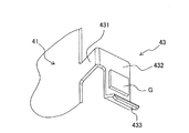
フレーム41の長辺の中央部近傍に設けられたグリップ検出用脚部43は、それぞれ、図4に示す通り、フレーム41から突出した部分を屈曲及び成形した部材であり、第1板部431と、第2板部432と、第3板部433とを有する。
The
第1板部431は、フレーム41と第2板部432とを接続する略正方形の平板である。第1板部431は、フレーム41の長辺から側方に突出し、フレーム41と同一面上に延在している。
The
第2板部432は、ひずみゲージGを取り付けるための矩形の平板であり、第2板部432の長辺方向はフレーム41の長辺方向に等しく、第2板部432の短辺方向はフレーム41に直交する前後方向に等しい。したがって、第2板部432は、フレーム41と直交してフレーム41の長辺方向に広がった面内に位置している。また第2板部432は、タッチ検出用脚部42の第2板部422と同一平面上に位置している。
The
第2板部432は、長辺方向の一端部の前側において第1板部431の先端に接続されている。また、第2板部432の長辺方向の他端部には、第3板部433が接続されている。
The
第2板部432の両面の、長辺方向の中央部近傍(より詳細には、グリップによりせん断応力が生じる場所)には、それぞれひずみゲージG(第1ひずみゲージ、又は第2ひずみゲージ)が取り付けられている。ひずみゲージGは、それぞれ、不図示の配線により制御部20のセンサ演算部21に接続されている。これら2つのひずみゲージGを用いたハーフブリッジ構成によれば、第2板部432に生じるひずみ(後述の曲げひずみ)を、1つのひずみゲージを用いた場合と比して約2倍の感度で検出することができる。
Strain gauges G (first strain gauges or second strain gauges) are respectively provided in the vicinity of the center part in the long side direction on both surfaces of the second plate part 432 (more specifically, where a shear stress is generated by the grip). It is attached. Each of the strain gauges G is connected to the
第3板部433は、図4に示す通り、フレーム41と直交に、且つ第2板部433に対して所定の角度を有して延在する2つの板部を組み合せた略L字形状を有する。第3板部433の、第2板部432と接続される端部とは反対側の端部は、筐体10の側面12の内面側に接触している。
As shown in FIG. 4, the
2つのグリップ検出用脚部43の各々は、筐体10の側板12に側方から荷重が加えられ、側板12に撓みが生じた際には、第1板部431がフレーム41に接触された状態で第3板部433がフレーム41に向かって移動し、第2板部432内に曲げひずみが生じる。センサ演算部21は、第2板部432に取り付けられたひずみゲージGを介して第2板部432内に生じた曲げひずみの大きさを検知し、この曲げひずみの大きさに基づいて2つのグリップ検出用脚部43の各々に加えられた荷重の大きさを求めることができる。すなわち、2つのグリップ検出用脚部43の各々と、センサ演算部21とにより、2つの荷重センサが構成されている。
In each of the two grip
以下では、説明の便宜上、図2において、フレーム41を前方から見て右側に設けられたグリップ検出用脚部43とセンサ演算部21とで構成される荷重センサを荷重センサLC5とし、フレーム41を前方から見て左側に設けられたグリップ検出用脚部43とセンサ演算部21とで構成される荷重センサを荷重センサLC6とする。
In the following, for convenience of explanation, in FIG. 2, the load sensor composed of the
タッチ検出用脚部42の第1板部421、第2板部422および第3板部423ならびにグリップ検出用脚部43の第1板部431、第2板部432および第3板部433は、それぞれフレーム41と同素材で一体に成形されることが好ましい。以上の構成によれば、例えば、フレーム41とは別素材でタッチ検出用脚部42の第1板部421、第2板部422、および、第3板部423ならびにグリップ検出用脚部43の第1板部431、第2板部432、および、第3板部433を形成し、タッチ検出用脚部42をフレーム41に対して溶接等により固定するとともに、グリップ検出用脚部43をフレーム41に対して溶接等により固定する構成と比較して、フレーム41とタッチ検出用脚部42との固定強度、および、フレーム41とグリップ検出用脚部43との固定強度が確保され、接続部の不規則な変形が低減される。したがって、以上の構成によれば高精度な荷重検出が可能になるという効果が実現される。
The
検出部材40は、一例として表示パネル部DUにより後方にわずかに付勢された状態で筐体10内に保持されてよい。この時、タッチ検出用脚部42の第3板部423の先端部と筐体10の背板11の内側面との間の摩擦抵抗により検出部材40は定位置に保持される。
As an example, the
次に、本実施形態のセンサユニットSUを用いて、タッチ位置及びタッチ強さを検出する動作について説明する。 Next, an operation for detecting a touch position and a touch strength using the sensor unit SU of the present embodiment will be described.
本明細書において「タッチ位置」とは、広義には携帯機器(本実施形態では携帯電話100)の利用者が、携帯機器に触れる位置を意味し、具体的には例えば、利用者が携帯機器のモニタ画面に触れる位置を意味する。本実施形態においては「タッチ位置」は、利用者が携帯電話100の透明カバー70に触れる位置であり、同時に利用者が携帯電話100の透明カバー70に触れることにより生じる荷重が、フレーム41に付与される位置である。
In this specification, the “touch position” means a position where a user of a mobile device (the
また、本明細書において「タッチ強さ」とは、広義には携帯機器(本実施形態では携帯電話100)の利用者が、携帯機器に触れる強さを意味し、具体的には例えば、利用者が携帯機器のモニタ画面を押圧する強さを意味する。本実施形態においては「タッチ強さ」は、利用者が携帯電話100の透明カバー70を押圧する強さであり、同時に利用者が携帯電話100の透明カバー70を押圧することによりフレーム41に加えられる荷重の大きさである。
Further, in this specification, “touch strength” means the strength with which a user of a mobile device (the
本実施形態の携帯電話100において、利用者が透明カバー70に前方から触れると、利用者の指が透明カバー70を後方に押す押圧力は、液晶パネル60とバックライト50とを介して、検出部材40のフレーム41に伝達され、フレーム41に荷重が加えられる。
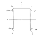
In the
ここで、フレーム41上の荷重が加えられる位置、及び加えられた荷重の大きさは、荷重センサLC1〜LC4を用いて求めることができる。具体的には例えば、図5に示す通り、フレーム41を前方からみて、長辺方向(上下方向)をX軸方向とし、短辺方向(左右方向)をY軸方向とする。この時、荷重センサLC1、LC2、LC3、LC4の座標をそれぞれ(X1、Y1)、(X2、Y2)、(X3、Y3)、(X4、Y4)、荷重センサLC1、LC2、LC3、LC4の荷重の検出値をそれぞれW1、W2、W3、W4とすると、センサ演算部21は、フレーム41上の重心位置(X、Y)、即ち荷重が加えられている位置(タッチ位置)を次式により算出する。
Here, the position on the

また、センサ演算部21は、フレーム41に加えられる荷重の強さW、即ちタッチ強さを次式により算出する。
Further, the
なお、本実施形態においては、グリップ検出用脚部43の第3板部433は、筐体10の側板12に対して前後方向に摺動可能な状態で接触している。そのため、フレーム41に前方から荷重が加えられ、フレーム41が後方に移動する際には、グリップ検出用脚部43は、第3板部433を筐体10の側板12の内面上を摺動させて自在に移動する。よって、フレーム41に前方から荷重が加えられた場合には、荷重センサLC5、LC6は荷重の検知には関与せず、荷重の検知は荷重センサLC1〜LC4のみで行われ、センサ演算部21は、(式1)、(式2)、(式3)を用いてタッチ位置、タッチ強さを求めることができる。
In the present embodiment, the
次に、本実施形態のセンサユニットSUを用いて、グリップ強さを検出する動作について説明する。 Next, an operation for detecting grip strength using the sensor unit SU of the present embodiment will be described.
本明細書において、「グリップ強さ」とは、広義には携帯機器(本実施形態では携帯電話100)の利用者が、携帯機器を握る強さを意味し、具体的には例えば、利用者が携帯機器の筐体を握る強さを意味する。本実施形態においては、「グリップ強さ」は、利用者が携帯電話100の筐体10の側板12を握ってこれを内側に向けて押圧する強さであり、利用者が側板12に付与する荷重の大きさである。
In this specification, “grip strength” means the strength with which a user of a mobile device (
したがって、本実施形態の携帯電話100においては、荷重センサLC5、LC6により検出される荷重の大きさが、即ちグリップ強さである。なお、荷重センサLC5の検出値と荷重センサLC6の検出値の和を「グリップ強さ」と定義してもよく、荷重センサLC5の検出値と荷重センサLC6の検出値をそれぞれ別個の「グリップ強さ」として扱い、例えば一方を右側グリップ強さ、他方を左側グリップ強さと定義してもよい。
Therefore, in the
本実施形態の携帯電話100の効果を以下にまとめる。
The effects of the
本実施形態の携帯電話100は、筐体10の内部に検出部材40を配置し、制御部20内にセンサ演算部21を構築するのみで、タッチ位置、タッチ強さ、グリップ強さを検出することができる。したがって本実施形態の携帯電話100は、簡素な構成で多様な検出を行うことができる。このような多様な検出により、携帯機器に斬新な操作感を与えることができる。
The
携帯電話100の検出部材40に含まれるフレーム41は、従来の携帯電話が一般に備える部材である。したがって本実施形態の携帯電話100は、従来の携帯電話に対して、それぞれ微小な部材であり携帯電話内のデッドスペースに配置可能な4つのタッチ検出用脚部42と2つのグリップ検出用脚部43を与えるのみで、タッチ位置、タッチ強さ、グリップ強さの検出を可能とするものであるともいえる。すなわち本実施形態の携帯電話100は、部品点数の増大や装置の複雑化を抑制しつつ、携帯機器に斬新な操作感を与えることができる。
The
本実施形態の携帯電話100は、検出部材40とセンサ演算部21とを含むセンサユニットSUにより、タッチ位置、タッチ強さの検出を行うことができる。したがって、抵抗膜方式や静電容量方式のタッチパネルを利用する必要がなく、薄型化を図ることができる。
The
本実施形態の携帯電話100は、6つの荷重センサLC1〜LC6備えているため、タッチ位置、タッチ強さ、グリップ強さを精度良く検出することができ、特にタッチ強さ及びグリップ強さを高精度に検出することができる。
Since the
<第2実施形態>
本発明の第2実施形態の携帯電話200について、図6、図7を参照して説明する。
Second Embodiment
A
第2実施形態の携帯電話200は、図6に示す通り、検出部材40’の形状が第1実施形態の携帯電話100の検出部材40と異なっている点を除いては、第1実施形態の携帯電話100と同一である。以下では、検出部材40’の構成、及び検出部材40’を備えることにより可能となるグリップ位置の検出についてのみ説明する。説明されない構造及び機能については、第1実施形態の携帯電話100と同一である。
As shown in FIG. 6, the
検出部材40’は、図7に示す通り、矩形状の平板であるフレーム41’と、フレーム41’の4つの角部にそれぞれ設けられた4つのタッチ検出用脚部42’と、4つのタッチ検出用脚部42’にそれぞれ隣接して設けられた4つのグリップ検出用脚部43’とを有する。フレーム41’、タッチ検出用脚部42’、グリップ検出用脚部43’の形状は、それぞれ、第1実施形態のフレーム41、タッチ検出用脚部42、グリップ検出用脚部43と同一である。
As shown in FIG. 7, the
検出部材40’は、4つのタッチ検出用脚部42’が筐体10の背板11に接触し、4つのグリップ検出用脚部43’が筐体10の側板12に前後方向に摺動可能に接触した状態で、筐体10の内部に収容されている。フレーム41’は、制御部20と電源30とを覆うように、これらの前方に配置される。
The
4つのグリップ検出用脚部43’にそれぞれ取り付けられたひずみゲージGは不図示の配線によりセンサ演算部21に接続されている。以下では、図7において、フレーム41’を前方から見て右上に設けられたグリップ検出用脚部43’とセンサ演算部21とによって構成される荷重センサを荷重センサLC7と呼ぶ。また、図7において、フレーム41’を前方から見て右下、左下、左上に設けられたグリップ検出用脚部43’とセンサ演算部21とによって構成される荷重センサを、それぞれ荷重センサLC8、LC9、LC10と呼ぶ。
The strain gauges G attached to the four grip detection legs 43 'are connected to the
第2実施形態の携帯電話200においては、フレーム41’の長辺方向の両端部近傍にそれぞれ荷重センサが構築されているため、グリップ強さに加えてグリップ位置も検出することができる。
In the
本明細書において「グリップ位置」とは、広義には携帯機器(本実施形態では携帯電話200)の利用者が、携帯機器を握る位置を意味し、具体的には例えば、利用者が携帯機器の筐体を握る位置を意味する。本実施形態においては「グリップ位置」は、利用者が携帯電話200の筐体10の側板12を握る位置であり、即ち利用者が携帯電話200の筐体10の側板12に荷重を加える位置である。
In this specification, “grip position” means a position where a user of a mobile device (
本実施形態におけるグリップ強さ及びグリップ位置の検出方法の一例は次の通りである。図8に示す通り、フレーム41’を前方からみて、長辺方向(上下方向)をX軸方向とし、短辺方向(左右方向)をY軸方向とする。この時、荷重センサLC7のX座標をX7、荷重センサLC8のX座標をX8、荷重センサLC7、LC8の荷重の検出値をそれぞれW7、W8とすると、センサ演算部21は、図8において+Y方向に加えられるグリップ力の大きさWG、即ちグリップ強さを次の式より求めることができる。
An example of the detection method of the grip strength and the grip position in the present embodiment is as follows. As shown in FIG. 8, when the
また、センサ演算部21は、X軸方向におけるグリップ力が加えられる位置XG、即ちグリップ位置を次の式より求めることができる。
Further, the
−Y方向に加えられるグリップ力のグリップ強さ及びグリップ位置も、荷重センサLC9のX座標をX9、LC10のX座標をX10とし、荷重センサLC9、LC10の荷重の検出値をそれぞれW9、W10として、(式4)、(式5)と同様の式により算出することができる。 Grip strength and gripping position of the gripping force applied to the -Y direction, the X-coordinate of the load sensor LC9 the X coordinate of the X 9, LC10 and X 10, the load sensor LC9, LC10 of the detected value of the load, respectively W 9 , W 10 can be calculated by the same equations as (Equation 4) and (Equation 5).
第2実施形態の携帯電話200によれば、第1実施形態の携帯電話100と同様の効果を奏することができる。
According to the
また、第2実施形態の携帯電話200は、第1実施形態の携帯電話100に対して、微小な部材であり携帯電話内のデッドスペースに配置可能なグリップ検出用脚部43を2つ追加するのみで、グリップ位置の検出も行うことができ、これにより斬新な操作感を与えることができる。
In addition, the
上記実施形態の携帯電話100、200において、次の変形態様を用いることもできる。
In the
第1実施形態の携帯電話100及び第2実施形態の携帯電話200は、それぞれタッチ検出用脚部42、42’とグリップ検出用脚部43、43’の両方を備えていたがこれには限られない。携帯電話100、200はそれぞれ、タッチ検出用脚部42、42’のみを備えてもよく、グリップ検出用脚部43、43’のみを備えてもよい。
The
第1実施形態の携帯電話100及び第2実施形態の携帯電話200は、それぞれ4つのタッチ検出用脚部42、42’を備えていたがこれには限られない。携帯電話100、200が備えるタッチ検出用脚部42、42’の数は任意である。タッチ検出用脚部42、42’を1つのみ有する場合は、タッチ位置の検出を行うことはできないが、タッチ強さの検出は行うことができる。また、タッチ検出脚部42、42’を2つのみ有する場合は、1軸方向におけるタッチ位置およびタッチ強さを検出することができる。タッチ検出脚部42、42’を3つ有する場合は、これらのタッチ検出脚部42、42’を1軸上に配置しない限り、2軸方向におけるタッチ位置およびタッチ強さを検出することができる。
The
第1実施形態の携帯電話100及び第2実施形態の携帯電話200においては、タッチ検出用脚部42、42’はフレーム41、41’の長辺に設けられていたが、これには限られない。タッチ検出用脚部42、42’はフレーム41、41’の短辺に設けられていてもよい。
In the
また、タッチ検出用脚部42、42’は必ずしもフレーム41、41’の角部に設けられる必要はない。タッチ検出用脚部42、42’の位置は、所望の領域においてタッチ強さ、タッチ位置の検出が行えるように適宜設定することができる。
Further, the
なお、本明細書において、フレーム41、41’の「四隅近傍」とは、フレーム41、41’の長辺方向においては、長辺方向の中央部までの距離よりも角部までの距離の方が近い位置を意味し、好ましくは長辺方向の一端部と中央部との間の距離をDとして、一端部から(1/4)D以内の距離にある点を意味する。また、フレーム41、41’の短辺方向においては、短辺方向の中央部までの距離よりも角部までの距離の方が近い位置を意味し、好ましくは短辺方向の一端部と中央部との間の距離をdとして、一端部から(1/4)d以内の距離にある点を意味する。
In the present specification, “near the four corners” of the
第1実施形態の携帯電話100及び第2実施形態の携帯電話200においては、グリップ検出用脚部43、43’はフレーム41、41’の長辺に設けられていたが、グリップ検出用脚部43、43’はフレーム41、41’の短辺に設けられていてもよい。また、フレーム41、41’の長辺上や短辺上におけるグリップ検出用脚部43、43’を設ける位置も任意である。グリップ検出用脚部43、43’は、フレーム41、41’の一対の長辺の一方に設けられるのみでもよく、一対の短辺の一方に設けられるのみでもよい。
In the
第1実施形態の携帯電話100の検出部材40が有するタッチ検出用脚部42、第2実施形態の携帯電話200の検出部材40’が有するタッチ検出用脚部42’においては第1板部421と第2板部422とが直交していたがこれには限られない。第1板部421と第2板部422とは、所定の角度を有して交差していてもよい。
The
第1実施形態の携帯電話100の検出部材40が有するタッチ検出用脚部42、第2実施形態の携帯電話200の検出部材40’が有するタッチ検出用脚部42’においては、ひずみゲージGは第2板部422の両面に取り付けられていたがこれには限られない。ひずみゲージGは第2板部422の片面に取り付けられるのみでもよい。或いは例えば、4つのひずみゲージGを用いたフルブリッジ構成によって、第2板部422に生じるせん断ひずみを1つのひずみゲージを用いた場合と比して約4倍の感度で検出できるようにしても良い。
In the
また、ひずみゲージGは第2板部422ではなく、第1板部421の両面又は片面にとりつけられてもよい。フレーム41、フレーム41’に荷重が加わった際には、第1板部421にも曲げひずみが生じるため、第1板部421に取り付けたひずみセンサGとセンサ演算部21とによって荷重センサを構築することができる。
Further, the strain gauge G may be attached to both surfaces or one surface of the
第1実施形態の携帯電話100の検出部材40が有するタッチ検出用脚部42、第2実施形態の携帯電話200の検出部材40’が有するタッチ検出用脚部42’は、第2板部422、第3板部423を有さず、ひずみゲージGが取り付けられた第1板部421を有するのみでもよい。この場合、第1板部421の先端部は、筐体10の側板12の内面側に取り付けられても良い。
The
このようなタッチ検出用脚部42、42’であっても、フレーム41、41’に荷重が加えられた際には第1板部421に曲げひずみが生じるため、センサ演算部21とともに荷重センサを構築することができる。
Even in the case of such
第1実施形態の携帯電話100の検出部材40が有するタッチ検出用脚部42、第2実施形態の携帯電話200の検出部材40’が有するタッチ検出用脚部42’において、第1板部421、第2板部422、第3板部423の形状は任意である。例えば、第1板部421は略正方形ではなく矩形等であってもよく、第2板部422は矩形ではなく略正方形等であってもよい。第3板部423は例えば平板状であってもよい。
In the touch
第1実施形態の携帯電話100の検出部材40が有するタッチ検出用脚部42とグリップ検出用脚部43、第2実施形態の携帯電話200の検出部材40’が有するタッチ検出用脚部42’とグリップ検出用脚部43’は、それぞれ複数の板状部材により構成されていたがこれには限られない。一例として、第1板部421、431、第3板部423、433は円柱状や角柱状であってもよい。また、第2板部422、432も、ひずみゲージGを取り付けることが可能な形状であれば板状には限られず、例えば円柱状や角柱状とすることができる。
第1実施形態の携帯電話100の検出部材40が有するグリップ検出用脚部43、第2実施形態の携帯電話200の検出部材40’が有するグリップ検出用脚部43’においては第1板部431と第2板部432とが直交していたがこれには限られない。第1板部431と第2板部432とは、所定の角度を有して交差していてもよい。
The
第1実施形態の携帯電話100の検出部材40が有するグリップ検出用脚部43、第2実施形態の携帯電話200の検出部材40’が有するグリップ検出用脚部43’においては、ひずみゲージGは第2板部432の両面に取り付けられていたがこれには限られない。ひずみゲージGは第2板部432の片面に取り付けられるのみでもよい。或いは例えば、4つのひずみゲージGを用いたフルブリッジ構成によって、第2板部432に生じる曲げひずみを1つのひずみゲージを用いた場合と比して約4倍の感度で検出できるようにしても良い。
In the
また、ひずみゲージGは第2板部432ではなく、第1板部431の両面又は片面にとりつけられてもよい。筐体10の側板12に荷重が加えられた際には、第1板部431にもせん断ひずみが生じるため、第1板部431に取り付けたひずみセンサGとセンサ演算部21とによって荷重センサを構築することができる。
Further, the strain gauge G may be attached to both surfaces or one surface of the
第1実施形態の携帯電話100の検出部材40が有するグリップ検出用脚部43、第2実施形態の携帯電話200の検出部材40’が有するグリップ検出用脚部43’において、第1板部431、第2板部432、第3板部433の形状は任意である。例えば、第1板部431は略正方形ではなく矩形等であってもよく、第2板部432は矩形ではなく略正方形等であってもよい。第3板部433は例えば平板状であってもよい。
In the
第1実施形態の携帯電話100の検出部材40が有するフレーム41、第2実施形態の携帯電話200の検出部材40’が有するフレーム41’は、いずれも矩形板には限られない。フレーム41、41’は、正方形やその他の多角形、円形、楕円形等の任意の形状であってよい。
The
第1実施形態の携帯電話100、第2実施形態の携帯電話200は、さらに抵抗膜方式や静電容量方式などの他の方式のタッチパネルを備えても良い。
The
第1実施形態、第2実施形態は携帯機器の一例として携帯電話を挙げて説明を行ったが、上記実施形態のセンサユニットSUを備える携帯機器は、携帯電話には限られない。例えば携帯用ゲーム機、携帯用音楽再生器、ノートパソコン、タブレット等において上記実施形態のセンサユニットSUを用いることもできる。 Although the first embodiment and the second embodiment have been described by taking a mobile phone as an example of the mobile device, the mobile device including the sensor unit SU of the above embodiment is not limited to the mobile phone. For example, the sensor unit SU of the above embodiment can be used in a portable game machine, a portable music player, a notebook computer, a tablet, or the like.
本発明の特徴を維持する限り、本発明は上記実施の形態に限定されるものではなく、本発明の技術的思想の範囲内で考えられるその他の形態についても、本発明の範囲内に含まれる。例えば、本発明の態様には、上述した検知部材(すなわち、フレームと、タッチ検出用脚部及びグリップ検出用脚部の少なくとも一方とで構成されるフレーム機構/構造)や、この検知部材とセンサ演算部とで構成されるセンサユニット等も含まれる。 As long as the characteristics of the present invention are maintained, the present invention is not limited to the above embodiments, and other forms conceivable within the scope of the technical idea of the present invention are also included in the scope of the present invention. . For example, the aspect of the present invention includes the above-described detection member (that is, a frame mechanism / structure including a frame and at least one of a touch detection leg and a grip detection leg), and the detection member and the sensor. Also included is a sensor unit configured with a calculation unit.
本発明によれば、携帯電話等の携帯機器に新規かつ斬新な操作感を与えることができる。 ADVANTAGE OF THE INVENTION According to this invention, a novel and novel operation feeling can be given to portable apparatuses, such as a mobile telephone.
10 筐体
20 制御部
21 センサ演算部(演算部)
30 電源
40、40’ 検知部材
41、41’ フレーム
42、42’ タッチ検出用脚部
421、431 第1板部
422、432 第2板部
423、433 第3板部
43、43’ グリップ検出用脚部
50 バックライト
60 液晶パネル
70 透明カバー
G ひずみゲージ
SU センサユニット
DU 表示パネル部
DESCRIPTION OF
30
Claims (6)
表示パネル部を載置する矩形のフレームと、
前記フレームの四隅近傍からそれぞれ延在する4つのタッチ検出用脚部と、
前記タッチ検出用脚部の各々に取り付けられた第1ひずみゲージと、
第1ひずみゲージの出力に基づいて前記タッチ位置及び前記タッチ強さを求める演算部と、
前記フレームの長辺から延在するグリップ検出用脚部と、
前記グリップ検出用脚部に取り付けられた第2ひずみゲージとを備え、
前記演算部は、第2ひずみゲージの出力に基づいて前記利用者が前記携帯機器を握る際のグリップ強さを求める携帯機器。 A portable device capable of detecting a touch position and a touch strength when a user touches the portable device,
A rectangular frame on which the display panel unit is placed;
Four touch detection legs respectively extending from near the four corners of the frame;
A first strain gauge attached to each of the touch detection legs;
A calculation unit for obtaining the touch position and the touch strength based on an output of the first strain gauge ;
A grip detection leg extending from the long side of the frame;
A second strain gauge attached to the grip detection leg,
The arithmetic unit, a mobile device the user based on the output of the second strain gauge Ru seeking grip strength when gripping the portable device.
表示パネル部を載置する矩形のフレームと、 A rectangular frame on which the display panel unit is placed;
前記フレームの四隅近傍からそれぞれ延在する4つのタッチ検出用脚部と、 Four touch detection legs respectively extending from near the four corners of the frame;
前記タッチ検出用脚部の各々に取り付けられた第1ひずみゲージと、 A first strain gauge attached to each of the touch detection legs;
第1ひずみゲージの出力に基づいて前記タッチ位置及び前記タッチ強さを求める演算部と、 A calculation unit for obtaining the touch position and the touch strength based on an output of the first strain gauge;
前記フレームの長辺から延在する複数のグリップ検出用脚部と、 A plurality of grip detection legs extending from the long side of the frame;
前記複数のグリップ検出用脚部の各々に取り付けられた第2ひずみゲージとを備え、 A second strain gauge attached to each of the plurality of grip detection legs,
前記演算部は、第2ひずみゲージの出力に基づいて前記利用者が前記携帯機器を握る際のグリップ強さ及びグリップ位置を求める携帯機器。 The said calculating part is a portable apparatus which calculates | requires the grip strength and grip position when the said user grips the said portable apparatus based on the output of a 2nd strain gauge.
前記4つのタッチ検出用脚部の各々は、前記筐体の内側において前記背面に接触している請求項1又は2に記載の携帯機器。 The portable device according to claim 1, wherein each of the four touch detection legs is in contact with the back surface inside the housing.
前記4つのタッチ検出用脚部の各々は、前記筐体の内側において前記背面に接触しており、前記グリップ検出用脚部は前記筐体の内側において前記側面に接触している請求項1又は2に記載の携帯機器。 The each of the four touch detection legs is in contact with the back surface inside the casing, and the grip detection legs are in contact with the side surfaces inside the casing. 2. The mobile device according to 2.
表示パネル部を載置するフレームと、 A frame on which the display panel unit is placed;
前記フレームからそれぞれ延在する少なくとも2つのタッチ検出用脚部と、 At least two touch detection legs each extending from the frame;
前記タッチ検出用脚部の各々に取り付けられた第1ひずみゲージと、 A first strain gauge attached to each of the touch detection legs;
第1ひずみゲージの出力に基づいて前記タッチ位置及び前記タッチ強さを求める演算部と、 A calculation unit for obtaining the touch position and the touch strength based on an output of the first strain gauge;
前記フレームから延在するグリップ検出用脚部と、 A grip detection leg extending from the frame;
前記グリップ検出用脚部に取り付けられた第2ひずみゲージとを備え、 A second strain gauge attached to the grip detection leg,
前記演算部は、第2ひずみゲージの出力に基づいて前記利用者が前記携帯機器を握る際のグリップ強さを求める携帯機器。 The computing unit is a portable device that calculates a grip strength when the user grips the portable device based on an output of a second strain gauge.
Priority Applications (5)
| Application Number | Priority Date | Filing Date | Title |
|---|---|---|---|
| JP2015250471A JP6470674B2 (en) | 2015-12-22 | 2015-12-22 | Portable device |
| US15/381,897 US10114506B2 (en) | 2015-12-22 | 2016-12-16 | Portable apparatus |
| CN201611182024.9A CN107015597B (en) | 2015-12-22 | 2016-12-20 | Portable device |
| CN201910614514.9A CN110471497B (en) | 2015-12-22 | 2016-12-20 | Portable device |
| US16/025,394 US10216326B2 (en) | 2015-12-22 | 2018-07-02 | Portable apparatus |
Applications Claiming Priority (1)
| Application Number | Priority Date | Filing Date | Title |
|---|---|---|---|
| JP2015250471A JP6470674B2 (en) | 2015-12-22 | 2015-12-22 | Portable device |
Related Child Applications (1)
| Application Number | Title | Priority Date | Filing Date |
|---|---|---|---|
| JP2019005693A Division JP6528013B2 (en) | 2019-01-17 | 2019-01-17 | Mobile device |
Publications (3)
| Publication Number | Publication Date |
|---|---|
| JP2017117124A JP2017117124A (en) | 2017-06-29 |
| JP2017117124A5 JP2017117124A5 (en) | 2018-11-08 |
| JP6470674B2 true JP6470674B2 (en) | 2019-02-13 |
Family
ID=59066229
Family Applications (1)
| Application Number | Title | Priority Date | Filing Date |
|---|---|---|---|
| JP2015250471A Active JP6470674B2 (en) | 2015-12-22 | 2015-12-22 | Portable device |
Country Status (3)
| Country | Link |
|---|---|
| US (2) | US10114506B2 (en) |
| JP (1) | JP6470674B2 (en) |
| CN (2) | CN107015597B (en) |
Families Citing this family (4)
| Publication number | Priority date | Publication date | Assignee | Title |
|---|---|---|---|---|
| US10782818B2 (en) * | 2018-08-29 | 2020-09-22 | Apple Inc. | Load cell array for detection of force input to an electronic device enclosure |
| US10812639B1 (en) | 2019-12-17 | 2020-10-20 | Robert Bosch Gmbh | Pressure chamber and associated pressure sensors for a mobile communication device |
| US10999421B1 (en) | 2019-12-17 | 2021-05-04 | Robert Bosch Gmbh | System and method for utilizing pressure sensors in an electric device |
| US11789540B1 (en) * | 2022-11-23 | 2023-10-17 | Kostal Of America, Inc. | Touch surface controller |
Family Cites Families (19)
| Publication number | Priority date | Publication date | Assignee | Title |
|---|---|---|---|---|
| US5241308A (en) * | 1990-02-22 | 1993-08-31 | Paragon Systems, Inc. | Force sensitive touch panel |
| US5742222A (en) * | 1995-05-26 | 1998-04-21 | Avi Systems, Inc. | Direct adhering polysilicon based strain gage |
| US5708460A (en) * | 1995-06-02 | 1998-01-13 | Avi Systems, Inc. | Touch screen |
| JP2006126997A (en) | 2004-10-27 | 2006-05-18 | Pfu Ltd | Three-dimensional touch panel |
| JP2007086990A (en) * | 2005-09-21 | 2007-04-05 | Smk Corp | Touch panel |
| US20080165159A1 (en) * | 2006-12-14 | 2008-07-10 | Soss David A | Force-based input device having a modular sensing component |
| JP5453351B2 (en) * | 2011-06-24 | 2014-03-26 | 株式会社Nttドコモ | Mobile information terminal, operation state determination method, program |
| JP5588931B2 (en) * | 2011-06-29 | 2014-09-10 | 株式会社Nttドコモ | Mobile information terminal, arrangement area acquisition method, program |
| US9880653B2 (en) * | 2012-04-30 | 2018-01-30 | Corning Incorporated | Pressure-sensing touch system utilizing total-internal reflection |
| KR101995486B1 (en) * | 2012-06-26 | 2019-07-02 | 엘지전자 주식회사 | Mobile terminal and control method thereof |
| WO2014149023A1 (en) * | 2013-03-15 | 2014-09-25 | Rinand Solutions Llc | Force sensing of inputs through strain analysis |
| US10078365B2 (en) * | 2013-04-19 | 2018-09-18 | Lg Electronics Inc. | Device for controlling mobile terminal and method of controlling the mobile terminal |
| KR102153006B1 (en) * | 2013-05-27 | 2020-09-07 | 삼성전자주식회사 | Method for processing input and an electronic device thereof |
| EP2816442B1 (en) * | 2013-06-20 | 2019-07-31 | Samsung Electronics Co., Ltd | Electronic device and method of controlling electronic device using grip sensing |
| JP5904174B2 (en) * | 2013-08-22 | 2016-04-13 | Smk株式会社 | Touch panel support structure |
| US10691332B2 (en) * | 2014-02-28 | 2020-06-23 | Samsung Electronics Company, Ltd. | Text input on an interactive display |
| CN104977994B (en) * | 2014-04-10 | 2018-02-13 | 台达电子工业股份有限公司 | Buckle module and its cabinet being applicable |
| JP6291340B2 (en) * | 2014-05-07 | 2018-03-14 | 富士ソフト株式会社 | Touch input device and input detection method |
| JP6120898B2 (en) * | 2015-03-27 | 2017-04-26 | 京セラ株式会社 | Electronic device and control method of electronic device |
-
2015
- 2015-12-22 JP JP2015250471A patent/JP6470674B2/en active Active
-
2016
- 2016-12-16 US US15/381,897 patent/US10114506B2/en active Active
- 2016-12-20 CN CN201611182024.9A patent/CN107015597B/en active Active
- 2016-12-20 CN CN201910614514.9A patent/CN110471497B/en active Active
-
2018
- 2018-07-02 US US16/025,394 patent/US10216326B2/en active Active
Also Published As
| Publication number | Publication date |
|---|---|
| US10216326B2 (en) | 2019-02-26 |
| CN110471497A (en) | 2019-11-19 |
| CN107015597B (en) | 2019-08-16 |
| CN107015597A (en) | 2017-08-04 |
| US20180321789A1 (en) | 2018-11-08 |
| JP2017117124A (en) | 2017-06-29 |
| CN110471497B (en) | 2021-03-12 |
| US20170177152A1 (en) | 2017-06-22 |
| US10114506B2 (en) | 2018-10-30 |
Similar Documents
| Publication | Publication Date | Title |
|---|---|---|
| JP6470674B2 (en) | Portable device | |
| JP6246640B2 (en) | Electronics | |
| US10126854B2 (en) | Providing touch position information | |
| JP4682357B2 (en) | Interface device with haptic touch panel | |
| CN103124951A (en) | Information processing device | |
| JP2016519819A (en) | A device that interacts with an electronic device and / or computer device in a non-contact manner, and a device including the device | |
| KR20190115673A (en) | Protective film attachable to electronic device and protective film package comprising the same | |
| JP2014115321A (en) | Display device | |
| CN114651224A (en) | Electronic device including sensor for detecting external input | |
| JP6528013B2 (en) | Mobile device | |
| JP2012216206A (en) | Electronic device | |
| TW201624258A (en) | Interface display control system and method for electronic device | |
| WO2015098061A1 (en) | Electronic instrument | |
| JP2015106174A (en) | Electronic apparatus | |
| US8823638B2 (en) | Optical navigation module with alignment features | |
| CN110300226A (en) | The control method of electronic equipment and its flashlight | |
| JP2020021334A (en) | Touch panel system for flexible display | |
| CN216122502U (en) | Electronic equipment material preparing shell assembly and electronic equipment | |
| JP6062351B2 (en) | Electronics | |
| JP2846185B2 (en) | Coordinate input device | |
| WO2013084820A1 (en) | Electronic apparatus | |
| JP4968353B2 (en) | Pointed position detecting device, pointed position detecting method and program | |
| EP2487562B1 (en) | Optical navigation module with alignment features | |
| TW201423486A (en) | A disply device with virtual keyboard | |
| TWI416386B (en) | Touch device and method |
Legal Events
| Date | Code | Title | Description |
|---|---|---|---|
| A521 | Written amendment |
Free format text: JAPANESE INTERMEDIATE CODE: A523 Effective date: 20181001 |
|
| A621 | Written request for application examination |
Free format text: JAPANESE INTERMEDIATE CODE: A621 Effective date: 20181001 |
|
| A871 | Explanation of circumstances concerning accelerated examination |
Free format text: JAPANESE INTERMEDIATE CODE: A871 Effective date: 20181001 |
|
| A975 | Report on accelerated examination |
Free format text: JAPANESE INTERMEDIATE CODE: A971005 Effective date: 20181128 |
|
| TRDD | Decision of grant or rejection written | ||
| A01 | Written decision to grant a patent or to grant a registration (utility model) |
Free format text: JAPANESE INTERMEDIATE CODE: A01 Effective date: 20190108 |
|
| A61 | First payment of annual fees (during grant procedure) |
Free format text: JAPANESE INTERMEDIATE CODE: A61 Effective date: 20190118 |
|
| R150 | Certificate of patent or registration of utility model |
Ref document number: 6470674 Country of ref document: JP Free format text: JAPANESE INTERMEDIATE CODE: R150 |