JP6470185B2 - Body structure imaging - Google Patents
Body structure imaging Download PDFInfo
- Publication number
- JP6470185B2 JP6470185B2 JP2015554305A JP2015554305A JP6470185B2 JP 6470185 B2 JP6470185 B2 JP 6470185B2 JP 2015554305 A JP2015554305 A JP 2015554305A JP 2015554305 A JP2015554305 A JP 2015554305A JP 6470185 B2 JP6470185 B2 JP 6470185B2
- Authority
- JP
- Japan
- Prior art keywords
- optionally
- image
- heart
- data
- anatomical
- Prior art date
- Legal status (The legal status is an assumption and is not a legal conclusion. Google has not performed a legal analysis and makes no representation as to the accuracy of the status listed.)
- Active
Links
- 238000003384 imaging method Methods 0.000 title claims description 178
- 238000000034 method Methods 0.000 claims description 227
- 230000001537 neural effect Effects 0.000 claims description 215
- 210000002216 heart Anatomy 0.000 claims description 159
- 230000000694 effects Effects 0.000 claims description 148
- 210000003403 autonomic nervous system Anatomy 0.000 claims description 136
- 238000002679 ablation Methods 0.000 claims description 134
- 238000011282 treatment Methods 0.000 claims description 115
- 238000001727 in vivo Methods 0.000 claims description 74
- 208000003098 Ganglion Cysts Diseases 0.000 claims description 62
- 208000005400 Synovial Cyst Diseases 0.000 claims description 62
- 230000000747 cardiac effect Effects 0.000 claims description 44
- 238000009826 distribution Methods 0.000 claims description 38
- 239000002872 contrast media Substances 0.000 claims description 34
- 230000004044 response Effects 0.000 claims description 34
- 230000000638 stimulation Effects 0.000 claims description 30
- 239000000523 sample Substances 0.000 claims description 26
- 230000000946 synaptic effect Effects 0.000 claims description 21
- 238000003745 diagnosis Methods 0.000 claims description 15
- 230000004936 stimulating effect Effects 0.000 claims description 7
- 230000008904 neural response Effects 0.000 claims description 6
- 230000002159 abnormal effect Effects 0.000 claims description 5
- 239000003814 drug Substances 0.000 claims description 5
- 238000012795 verification Methods 0.000 claims description 5
- 229940079593 drug Drugs 0.000 claims description 4
- 238000013439 planning Methods 0.000 claims description 3
- 238000002681 cryosurgery Methods 0.000 claims description 2
- 239000003053 toxin Substances 0.000 claims description 2
- 231100000765 toxin Toxicity 0.000 claims description 2
- 210000001519 tissue Anatomy 0.000 description 285
- 210000000056 organ Anatomy 0.000 description 104
- PDWUPXJEEYOOTR-UHFFFAOYSA-N 2-[(3-iodophenyl)methyl]guanidine Chemical group NC(=N)NCC1=CC=CC(I)=C1 PDWUPXJEEYOOTR-UHFFFAOYSA-N 0.000 description 62
- 238000002603 single-photon emission computed tomography Methods 0.000 description 57
- 210000000609 ganglia Anatomy 0.000 description 42
- 238000002591 computed tomography Methods 0.000 description 35
- 210000005240 left ventricle Anatomy 0.000 description 34
- 210000005036 nerve Anatomy 0.000 description 34
- 239000000700 radioactive tracer Substances 0.000 description 34
- 210000000577 adipose tissue Anatomy 0.000 description 33
- 210000000944 nerve tissue Anatomy 0.000 description 31
- 210000005242 cardiac chamber Anatomy 0.000 description 28
- 238000005259 measurement Methods 0.000 description 28
- 230000006870 function Effects 0.000 description 26
- 230000004807 localization Effects 0.000 description 26
- 210000000225 synapse Anatomy 0.000 description 26
- 230000000875 corresponding effect Effects 0.000 description 25
- 238000013507 mapping Methods 0.000 description 24
- 210000003484 anatomy Anatomy 0.000 description 22
- 238000012545 processing Methods 0.000 description 20
- 238000002604 ultrasonography Methods 0.000 description 20
- 230000001746 atrial effect Effects 0.000 description 19
- 201000010099 disease Diseases 0.000 description 18
- 208000037265 diseases, disorders, signs and symptoms Diseases 0.000 description 18
- 230000008569 process Effects 0.000 description 17
- 210000002837 heart atrium Anatomy 0.000 description 16
- 206010003658 Atrial Fibrillation Diseases 0.000 description 15
- 230000005714 functional activity Effects 0.000 description 15
- 230000002596 correlated effect Effects 0.000 description 14
- 230000030214 innervation Effects 0.000 description 14
- 238000004088 simulation Methods 0.000 description 14
- 210000003734 kidney Anatomy 0.000 description 13
- 238000012544 monitoring process Methods 0.000 description 13
- 230000002107 myocardial effect Effects 0.000 description 12
- 210000000653 nervous system Anatomy 0.000 description 12
- 230000006399 behavior Effects 0.000 description 11
- 210000003205 muscle Anatomy 0.000 description 11
- 210000003492 pulmonary vein Anatomy 0.000 description 11
- 230000035790 physiological processes and functions Effects 0.000 description 10
- 230000035945 sensitivity Effects 0.000 description 10
- 230000002889 sympathetic effect Effects 0.000 description 10
- 238000002560 therapeutic procedure Methods 0.000 description 10
- 230000004913 activation Effects 0.000 description 9
- 210000004369 blood Anatomy 0.000 description 9
- 239000008280 blood Substances 0.000 description 9
- 238000001514 detection method Methods 0.000 description 9
- 210000005246 left atrium Anatomy 0.000 description 9
- 238000002595 magnetic resonance imaging Methods 0.000 description 9
- 210000004165 myocardium Anatomy 0.000 description 9
- 210000005241 right ventricle Anatomy 0.000 description 9
- 238000001228 spectrum Methods 0.000 description 9
- 239000000126 substance Substances 0.000 description 9
- 210000001124 body fluid Anatomy 0.000 description 8
- 238000010586 diagram Methods 0.000 description 8
- 238000002347 injection Methods 0.000 description 8
- 239000007924 injection Substances 0.000 description 8
- 210000004185 liver Anatomy 0.000 description 8
- 230000005855 radiation Effects 0.000 description 8
- 239000012217 radiopharmaceutical Substances 0.000 description 8
- 229940121896 radiopharmaceutical Drugs 0.000 description 8
- 230000002799 radiopharmaceutical effect Effects 0.000 description 8
- SFLSHLFXELFNJZ-QMMMGPOBSA-N (-)-norepinephrine Chemical compound NC[C@H](O)C1=CC=C(O)C(O)=C1 SFLSHLFXELFNJZ-QMMMGPOBSA-N 0.000 description 7
- 206010003119 arrhythmia Diseases 0.000 description 7
- 210000001367 artery Anatomy 0.000 description 7
- 239000010839 body fluid Substances 0.000 description 7
- 238000004364 calculation method Methods 0.000 description 7
- 230000008859 change Effects 0.000 description 7
- 238000004891 communication Methods 0.000 description 7
- 229960002748 norepinephrine Drugs 0.000 description 7
- SFLSHLFXELFNJZ-UHFFFAOYSA-N norepinephrine Natural products NCC(O)C1=CC=C(O)C(O)=C1 SFLSHLFXELFNJZ-UHFFFAOYSA-N 0.000 description 7
- 238000010606 normalization Methods 0.000 description 7
- 238000009206 nuclear medicine Methods 0.000 description 7
- 210000002784 stomach Anatomy 0.000 description 7
- 210000000709 aorta Anatomy 0.000 description 6
- 210000004204 blood vessel Anatomy 0.000 description 6
- 239000010410 layer Substances 0.000 description 6
- 210000004126 nerve fiber Anatomy 0.000 description 6
- 238000002600 positron emission tomography Methods 0.000 description 6
- 238000012360 testing method Methods 0.000 description 6
- 230000001225 therapeutic effect Effects 0.000 description 6
- 206010020772 Hypertension Diseases 0.000 description 5
- 238000011298 ablation treatment Methods 0.000 description 5
- 238000004458 analytical method Methods 0.000 description 5
- 230000006793 arrhythmia Effects 0.000 description 5
- 230000002638 denervation Effects 0.000 description 5
- 210000000936 intestine Anatomy 0.000 description 5
- 239000000463 material Substances 0.000 description 5
- 238000003672 processing method Methods 0.000 description 5
- 230000011218 segmentation Effects 0.000 description 5
- 210000002820 sympathetic nervous system Anatomy 0.000 description 5
- 210000003050 axon Anatomy 0.000 description 4
- 239000000835 fiber Substances 0.000 description 4
- 206010020871 hypertrophic cardiomyopathy Diseases 0.000 description 4
- 239000003550 marker Substances 0.000 description 4
- 239000000203 mixture Substances 0.000 description 4
- 230000001734 parasympathetic effect Effects 0.000 description 4
- 230000004043 responsiveness Effects 0.000 description 4
- 210000005245 right atrium Anatomy 0.000 description 4
- 230000028327 secretion Effects 0.000 description 4
- 210000000952 spleen Anatomy 0.000 description 4
- 210000005010 torso Anatomy 0.000 description 4
- 210000003932 urinary bladder Anatomy 0.000 description 4
- 206010019280 Heart failures Diseases 0.000 description 3
- 206010028980 Neoplasm Diseases 0.000 description 3
- 238000010317 ablation therapy Methods 0.000 description 3
- 210000002376 aorta thoracic Anatomy 0.000 description 3
- 230000017531 blood circulation Effects 0.000 description 3
- 238000004422 calculation algorithm Methods 0.000 description 3
- 201000011510 cancer Diseases 0.000 description 3
- 210000001011 carotid body Anatomy 0.000 description 3
- 150000001875 compounds Chemical class 0.000 description 3
- 210000002808 connective tissue Anatomy 0.000 description 3
- 230000008602 contraction Effects 0.000 description 3
- 238000002594 fluoroscopy Methods 0.000 description 3
- 208000019622 heart disease Diseases 0.000 description 3
- 239000011796 hollow space material Substances 0.000 description 3
- 230000003993 interaction Effects 0.000 description 3
- 230000033001 locomotion Effects 0.000 description 3
- 210000001165 lymph node Anatomy 0.000 description 3
- 238000004519 manufacturing process Methods 0.000 description 3
- 230000008035 nerve activity Effects 0.000 description 3
- 210000001640 nerve ending Anatomy 0.000 description 3
- 230000036961 partial effect Effects 0.000 description 3
- 230000037361 pathway Effects 0.000 description 3
- 230000000737 periodic effect Effects 0.000 description 3
- 230000002093 peripheral effect Effects 0.000 description 3
- 210000002254 renal artery Anatomy 0.000 description 3
- 238000003860 storage Methods 0.000 description 3
- 230000001360 synchronised effect Effects 0.000 description 3
- 230000002861 ventricular Effects 0.000 description 3
- 102100030426 Gastrotropin Human genes 0.000 description 2
- 241000703391 Lipovnik virus Species 0.000 description 2
- UCTWMZQNUQWSLP-UHFFFAOYSA-N adrenaline Chemical compound CNCC(O)C1=CC=C(O)C(O)=C1 UCTWMZQNUQWSLP-UHFFFAOYSA-N 0.000 description 2
- 238000011888 autopsy Methods 0.000 description 2
- 230000000903 blocking effect Effects 0.000 description 2
- 210000000746 body region Anatomy 0.000 description 2
- 229940030602 cardiac therapy drug Drugs 0.000 description 2
- 238000013153 catheter ablation Methods 0.000 description 2
- 239000003795 chemical substances by application Substances 0.000 description 2
- 230000001447 compensatory effect Effects 0.000 description 2
- 210000003748 coronary sinus Anatomy 0.000 description 2
- 238000012937 correction Methods 0.000 description 2
- 230000005574 cross-species transmission Effects 0.000 description 2
- 230000006378 damage Effects 0.000 description 2
- 230000007423 decrease Effects 0.000 description 2
- 230000003247 decreasing effect Effects 0.000 description 2
- 206010012601 diabetes mellitus Diseases 0.000 description 2
- 230000003205 diastolic effect Effects 0.000 description 2
- 230000004069 differentiation Effects 0.000 description 2
- 230000029087 digestion Effects 0.000 description 2
- VYFYYTLLBUKUHU-UHFFFAOYSA-N dopamine Chemical compound NCCC1=CC=C(O)C(O)=C1 VYFYYTLLBUKUHU-UHFFFAOYSA-N 0.000 description 2
- 210000002049 efferent pathway Anatomy 0.000 description 2
- 238000005516 engineering process Methods 0.000 description 2
- 210000000105 enteric nervous system Anatomy 0.000 description 2
- 238000001914 filtration Methods 0.000 description 2
- 238000002599 functional magnetic resonance imaging Methods 0.000 description 2
- 230000002496 gastric effect Effects 0.000 description 2
- 210000004907 gland Anatomy 0.000 description 2
- 210000003361 heart septum Anatomy 0.000 description 2
- 210000005161 hepatic lobe Anatomy 0.000 description 2
- 238000001802 infusion Methods 0.000 description 2
- 238000003780 insertion Methods 0.000 description 2
- 230000037431 insertion Effects 0.000 description 2
- 239000002346 layers by function Substances 0.000 description 2
- 210000003041 ligament Anatomy 0.000 description 2
- 230000000670 limiting effect Effects 0.000 description 2
- 210000000713 mesentery Anatomy 0.000 description 2
- 230000004060 metabolic process Effects 0.000 description 2
- 229940102859 methylene diphosphonate Drugs 0.000 description 2
- 230000005012 migration Effects 0.000 description 2
- 238000013508 migration Methods 0.000 description 2
- 238000012986 modification Methods 0.000 description 2
- 230000004048 modification Effects 0.000 description 2
- 210000002569 neuron Anatomy 0.000 description 2
- 210000005037 parasympathetic nerve Anatomy 0.000 description 2
- 230000010412 perfusion Effects 0.000 description 2
- 230000004962 physiological condition Effects 0.000 description 2
- 231100000614 poison Toxicity 0.000 description 2
- 239000002574 poison Substances 0.000 description 2
- 230000002685 pulmonary effect Effects 0.000 description 2
- 238000011084 recovery Methods 0.000 description 2
- 230000008660 renal denervation Effects 0.000 description 2
- 230000003252 repetitive effect Effects 0.000 description 2
- 210000002460 smooth muscle Anatomy 0.000 description 2
- 108010003524 sodium-bile acid cotransporter Proteins 0.000 description 2
- 210000002700 urine Anatomy 0.000 description 2
- 210000005166 vasculature Anatomy 0.000 description 2
- 210000002620 vena cava superior Anatomy 0.000 description 2
- 210000000596 ventricular septum Anatomy 0.000 description 2
- UCTWMZQNUQWSLP-VIFPVBQESA-N (R)-adrenaline Chemical compound CNC[C@H](O)C1=CC=C(O)C(O)=C1 UCTWMZQNUQWSLP-VIFPVBQESA-N 0.000 description 1
- 229930182837 (R)-adrenaline Natural products 0.000 description 1
- 108030001720 Bontoxilysin Proteins 0.000 description 1
- 208000020446 Cardiac disease Diseases 0.000 description 1
- 206010007559 Cardiac failure congestive Diseases 0.000 description 1
- 208000031229 Cardiomyopathies Diseases 0.000 description 1
- 206010008469 Chest discomfort Diseases 0.000 description 1
- 208000017667 Chronic Disease Diseases 0.000 description 1
- 206010061818 Disease progression Diseases 0.000 description 1
- 208000032928 Dyslipidaemia Diseases 0.000 description 1
- LFQSCWFLJHTTHZ-UHFFFAOYSA-N Ethanol Chemical compound CCO LFQSCWFLJHTTHZ-UHFFFAOYSA-N 0.000 description 1
- 206010020880 Hypertrophy Diseases 0.000 description 1
- 208000017170 Lipid metabolism disease Diseases 0.000 description 1
- 206010027476 Metastases Diseases 0.000 description 1
- 206010027452 Metastases to bone Diseases 0.000 description 1
- 206010027727 Mitral valve incompetence Diseases 0.000 description 1
- 206010028851 Necrosis Diseases 0.000 description 1
- HWZUDASOMGNLSM-UHFFFAOYSA-N O=P1OCOP(=O)O1 Chemical compound O=P1OCOP(=O)O1 HWZUDASOMGNLSM-UHFFFAOYSA-N 0.000 description 1
- 206010053159 Organ failure Diseases 0.000 description 1
- 102000009843 Thyroglobulin Human genes 0.000 description 1
- 108010034949 Thyroglobulin Proteins 0.000 description 1
- 208000024770 Thyroid neoplasm Diseases 0.000 description 1
- 108010066702 Thyrotropin Alfa Proteins 0.000 description 1
- 108010057266 Type A Botulinum Toxins Proteins 0.000 description 1
- 208000033774 Ventricular Remodeling Diseases 0.000 description 1
- 206010047281 Ventricular arrhythmia Diseases 0.000 description 1
- 210000001015 abdomen Anatomy 0.000 description 1
- 210000000683 abdominal cavity Anatomy 0.000 description 1
- 230000009102 absorption Effects 0.000 description 1
- 238000010521 absorption reaction Methods 0.000 description 1
- OIPILFWXSMYKGL-UHFFFAOYSA-N acetylcholine Chemical compound CC(=O)OCC[N+](C)(C)C OIPILFWXSMYKGL-UHFFFAOYSA-N 0.000 description 1
- 229960004373 acetylcholine Drugs 0.000 description 1
- 210000004100 adrenal gland Anatomy 0.000 description 1
- 230000001800 adrenalinergic effect Effects 0.000 description 1
- 210000003626 afferent pathway Anatomy 0.000 description 1
- 238000013528 artificial neural network Methods 0.000 description 1
- 230000002567 autonomic effect Effects 0.000 description 1
- 230000004888 barrier function Effects 0.000 description 1
- 239000002876 beta blocker Substances 0.000 description 1
- 229940097320 beta blocking agent Drugs 0.000 description 1
- 230000033228 biological regulation Effects 0.000 description 1
- 230000015572 biosynthetic process Effects 0.000 description 1
- 230000036772 blood pressure Effects 0.000 description 1
- 238000009534 blood test Methods 0.000 description 1
- 210000000988 bone and bone Anatomy 0.000 description 1
- 229940089093 botox Drugs 0.000 description 1
- 229940053031 botulinum toxin Drugs 0.000 description 1
- 238000002564 cardiac stress test Methods 0.000 description 1
- 210000004027 cell Anatomy 0.000 description 1
- 210000003169 central nervous system Anatomy 0.000 description 1
- 238000012512 characterization method Methods 0.000 description 1
- 210000004240 ciliary body Anatomy 0.000 description 1
- 238000012790 confirmation Methods 0.000 description 1
- 238000010276 construction Methods 0.000 description 1
- 229940039231 contrast media Drugs 0.000 description 1
- 230000006735 deficit Effects 0.000 description 1
- 230000001419 dependent effect Effects 0.000 description 1
- 238000002405 diagnostic procedure Methods 0.000 description 1
- 230000005750 disease progression Effects 0.000 description 1
- 229960003638 dopamine Drugs 0.000 description 1
- 238000012377 drug delivery Methods 0.000 description 1
- 230000009977 dual effect Effects 0.000 description 1
- 230000004064 dysfunction Effects 0.000 description 1
- 238000002001 electrophysiology Methods 0.000 description 1
- 230000007831 electrophysiology Effects 0.000 description 1
- 230000002124 endocrine Effects 0.000 description 1
- 229960005139 epinephrine Drugs 0.000 description 1
- 238000011156 evaluation Methods 0.000 description 1
- 230000003203 everyday effect Effects 0.000 description 1
- 230000005284 excitation Effects 0.000 description 1
- 230000003631 expected effect Effects 0.000 description 1
- 238000002474 experimental method Methods 0.000 description 1
- 238000000605 extraction Methods 0.000 description 1
- 210000001508 eye Anatomy 0.000 description 1
- 210000001105 femoral artery Anatomy 0.000 description 1
- 239000012530 fluid Substances 0.000 description 1
- 238000013467 fragmentation Methods 0.000 description 1
- 238000006062 fragmentation reaction Methods 0.000 description 1
- 210000001035 gastrointestinal tract Anatomy 0.000 description 1
- 230000012010 growth Effects 0.000 description 1
- 208000037824 growth disorder Diseases 0.000 description 1
- 210000003128 head Anatomy 0.000 description 1
- 230000035876 healing Effects 0.000 description 1
- 210000005003 heart tissue Anatomy 0.000 description 1
- 230000003054 hormonal effect Effects 0.000 description 1
- 238000003709 image segmentation Methods 0.000 description 1
- 230000002401 inhibitory effect Effects 0.000 description 1
- 230000005764 inhibitory process Effects 0.000 description 1
- 238000009434 installation Methods 0.000 description 1
- 230000010354 integration Effects 0.000 description 1
- 230000000968 intestinal effect Effects 0.000 description 1
- 230000002427 irreversible effect Effects 0.000 description 1
- 208000002551 irritable bowel syndrome Diseases 0.000 description 1
- 229940078979 liver therapy drug Drugs 0.000 description 1
- 210000004072 lung Anatomy 0.000 description 1
- 238000007726 management method Methods 0.000 description 1
- 230000000873 masking effect Effects 0.000 description 1
- 239000011159 matrix material Substances 0.000 description 1
- 230000007246 mechanism Effects 0.000 description 1
- 210000001370 mediastinum Anatomy 0.000 description 1
- 230000009401 metastasis Effects 0.000 description 1
- 230000001394 metastastic effect Effects 0.000 description 1
- 206010061289 metastatic neoplasm Diseases 0.000 description 1
- 230000027939 micturition Effects 0.000 description 1
- 238000000491 multivariate analysis Methods 0.000 description 1
- 230000003680 myocardial damage Effects 0.000 description 1
- 208000010125 myocardial infarction Diseases 0.000 description 1
- 208000031225 myocardial ischemia Diseases 0.000 description 1
- 210000001087 myotubule Anatomy 0.000 description 1
- WLRGEKXAJZHVHX-UHFFFAOYSA-N n-(2-methoxy-2-methylpropyl)methanimine;technetium(6+) Chemical compound [Tc+6].COC(C)(C)CN=[CH-].COC(C)(C)CN=[CH-].COC(C)(C)CN=[CH-].COC(C)(C)CN=[CH-].COC(C)(C)CN=[CH-].COC(C)(C)CN=[CH-] WLRGEKXAJZHVHX-UHFFFAOYSA-N 0.000 description 1
- 230000017074 necrotic cell death Effects 0.000 description 1
- 230000007433 nerve pathway Effects 0.000 description 1
- 230000007383 nerve stimulation Effects 0.000 description 1
- 230000003227 neuromodulating effect Effects 0.000 description 1
- 230000004007 neuromodulation Effects 0.000 description 1
- 239000002858 neurotransmitter agent Substances 0.000 description 1
- 230000003287 optical effect Effects 0.000 description 1
- 238000005457 optimization Methods 0.000 description 1
- 230000008520 organization Effects 0.000 description 1
- 230000001151 other effect Effects 0.000 description 1
- 210000000496 pancreas Anatomy 0.000 description 1
- 210000000192 parasympathetic ganglia Anatomy 0.000 description 1
- 210000001002 parasympathetic nervous system Anatomy 0.000 description 1
- 210000004738 parenchymal cell Anatomy 0.000 description 1
- 230000001314 paroxysmal effect Effects 0.000 description 1
- 230000007170 pathology Effects 0.000 description 1
- 230000008855 peristalsis Effects 0.000 description 1
- 230000000144 pharmacologic effect Effects 0.000 description 1
- 238000004393 prognosis Methods 0.000 description 1
- 210000001147 pulmonary artery Anatomy 0.000 description 1
- 238000001303 quality assessment method Methods 0.000 description 1
- 238000007674 radiofrequency ablation Methods 0.000 description 1
- 230000009467 reduction Effects 0.000 description 1
- 230000002829 reductive effect Effects 0.000 description 1
- 230000008929 regeneration Effects 0.000 description 1
- 238000011069 regeneration method Methods 0.000 description 1
- 230000001105 regulatory effect Effects 0.000 description 1
- 230000007832 reinnervation Effects 0.000 description 1
- 238000007634 remodeling Methods 0.000 description 1
- 238000009877 rendering Methods 0.000 description 1
- 230000001850 reproductive effect Effects 0.000 description 1
- 238000002271 resection Methods 0.000 description 1
- 230000000241 respiratory effect Effects 0.000 description 1
- 230000029058 respiratory gaseous exchange Effects 0.000 description 1
- 230000002441 reversible effect Effects 0.000 description 1
- 229920006395 saturated elastomer Polymers 0.000 description 1
- 238000012216 screening Methods 0.000 description 1
- 210000002966 serum Anatomy 0.000 description 1
- 210000003594 spinal ganglia Anatomy 0.000 description 1
- 230000003068 static effect Effects 0.000 description 1
- 230000002459 sustained effect Effects 0.000 description 1
- 210000000331 sympathetic ganglia Anatomy 0.000 description 1
- 208000024891 symptom Diseases 0.000 description 1
- 230000008685 targeting Effects 0.000 description 1
- 229960000617 technetium (99mtc) sestamibi Drugs 0.000 description 1
- 238000010998 test method Methods 0.000 description 1
- 229940124597 therapeutic agent Drugs 0.000 description 1
- 229960002175 thyroglobulin Drugs 0.000 description 1
- 201000002510 thyroid cancer Diseases 0.000 description 1
- 230000000451 tissue damage Effects 0.000 description 1
- 231100000827 tissue damage Toxicity 0.000 description 1
- 238000003325 tomography Methods 0.000 description 1
- 238000011269 treatment regimen Methods 0.000 description 1
- WFKWXMTUELFFGS-UHFFFAOYSA-N tungsten Chemical compound [W] WFKWXMTUELFFGS-UHFFFAOYSA-N 0.000 description 1
- 229910052721 tungsten Inorganic materials 0.000 description 1
- 239000010937 tungsten Substances 0.000 description 1
- 238000011144 upstream manufacturing Methods 0.000 description 1
- 230000001515 vagal effect Effects 0.000 description 1
- 210000001186 vagus nerve Anatomy 0.000 description 1
- 238000010200 validation analysis Methods 0.000 description 1
- 210000003462 vein Anatomy 0.000 description 1
- 210000001631 vena cava inferior Anatomy 0.000 description 1
- 230000000007 visual effect Effects 0.000 description 1
- XLYOFNOQVPJJNP-UHFFFAOYSA-N water Substances O XLYOFNOQVPJJNP-UHFFFAOYSA-N 0.000 description 1
- 230000003313 weakening effect Effects 0.000 description 1
Images


Classifications
-
- A—HUMAN NECESSITIES
- A61—MEDICAL OR VETERINARY SCIENCE; HYGIENE
- A61B—DIAGNOSIS; SURGERY; IDENTIFICATION
- A61B18/00—Surgical instruments, devices or methods for transferring non-mechanical forms of energy to or from the body
- A61B18/04—Surgical instruments, devices or methods for transferring non-mechanical forms of energy to or from the body by heating
- A61B18/12—Surgical instruments, devices or methods for transferring non-mechanical forms of energy to or from the body by heating by passing a current through the tissue to be heated, e.g. high-frequency current
- A61B18/14—Probes or electrodes therefor
- A61B18/1492—Probes or electrodes therefor having a flexible, catheter-like structure, e.g. for heart ablation
-
- A—HUMAN NECESSITIES
- A61—MEDICAL OR VETERINARY SCIENCE; HYGIENE
- A61B—DIAGNOSIS; SURGERY; IDENTIFICATION
- A61B5/00—Measuring for diagnostic purposes; Identification of persons
- A61B5/0033—Features or image-related aspects of imaging apparatus classified in A61B5/00, e.g. for MRI, optical tomography or impedance tomography apparatus; arrangements of imaging apparatus in a room
- A61B5/0035—Features or image-related aspects of imaging apparatus classified in A61B5/00, e.g. for MRI, optical tomography or impedance tomography apparatus; arrangements of imaging apparatus in a room adapted for acquisition of images from more than one imaging mode, e.g. combining MRI and optical tomography
-
- A—HUMAN NECESSITIES
- A61—MEDICAL OR VETERINARY SCIENCE; HYGIENE
- A61B—DIAGNOSIS; SURGERY; IDENTIFICATION
- A61B5/00—Measuring for diagnostic purposes; Identification of persons
- A61B5/0033—Features or image-related aspects of imaging apparatus classified in A61B5/00, e.g. for MRI, optical tomography or impedance tomography apparatus; arrangements of imaging apparatus in a room
- A61B5/004—Features or image-related aspects of imaging apparatus classified in A61B5/00, e.g. for MRI, optical tomography or impedance tomography apparatus; arrangements of imaging apparatus in a room adapted for image acquisition of a particular organ or body part
- A61B5/0044—Features or image-related aspects of imaging apparatus classified in A61B5/00, e.g. for MRI, optical tomography or impedance tomography apparatus; arrangements of imaging apparatus in a room adapted for image acquisition of a particular organ or body part for the heart
-
- A—HUMAN NECESSITIES
- A61—MEDICAL OR VETERINARY SCIENCE; HYGIENE
- A61B—DIAGNOSIS; SURGERY; IDENTIFICATION
- A61B5/00—Measuring for diagnostic purposes; Identification of persons
- A61B5/40—Detecting, measuring or recording for evaluating the nervous system
- A61B5/4029—Detecting, measuring or recording for evaluating the nervous system for evaluating the peripheral nervous systems
- A61B5/4035—Evaluating the autonomic nervous system
-
- A—HUMAN NECESSITIES
- A61—MEDICAL OR VETERINARY SCIENCE; HYGIENE
- A61B—DIAGNOSIS; SURGERY; IDENTIFICATION
- A61B5/00—Measuring for diagnostic purposes; Identification of persons
- A61B5/40—Detecting, measuring or recording for evaluating the nervous system
- A61B5/4029—Detecting, measuring or recording for evaluating the nervous system for evaluating the peripheral nervous systems
- A61B5/4041—Evaluating nerves condition
-
- A—HUMAN NECESSITIES
- A61—MEDICAL OR VETERINARY SCIENCE; HYGIENE
- A61B—DIAGNOSIS; SURGERY; IDENTIFICATION
- A61B5/00—Measuring for diagnostic purposes; Identification of persons
- A61B5/72—Signal processing specially adapted for physiological signals or for diagnostic purposes
-
- A—HUMAN NECESSITIES
- A61—MEDICAL OR VETERINARY SCIENCE; HYGIENE
- A61B—DIAGNOSIS; SURGERY; IDENTIFICATION
- A61B5/00—Measuring for diagnostic purposes; Identification of persons
- A61B5/74—Details of notification to user or communication with user or patient ; user input means
- A61B5/742—Details of notification to user or communication with user or patient ; user input means using visual displays
- A61B5/7425—Displaying combinations of multiple images regardless of image source, e.g. displaying a reference anatomical image with a live image
-
- A—HUMAN NECESSITIES
- A61—MEDICAL OR VETERINARY SCIENCE; HYGIENE
- A61B—DIAGNOSIS; SURGERY; IDENTIFICATION
- A61B6/00—Apparatus or devices for radiation diagnosis; Apparatus or devices for radiation diagnosis combined with radiation therapy equipment
- A61B6/02—Arrangements for diagnosis sequentially in different planes; Stereoscopic radiation diagnosis
- A61B6/03—Computed tomography [CT]
- A61B6/032—Transmission computed tomography [CT]
-
- A—HUMAN NECESSITIES
- A61—MEDICAL OR VETERINARY SCIENCE; HYGIENE
- A61B—DIAGNOSIS; SURGERY; IDENTIFICATION
- A61B6/00—Apparatus or devices for radiation diagnosis; Apparatus or devices for radiation diagnosis combined with radiation therapy equipment
- A61B6/48—Diagnostic techniques
- A61B6/481—Diagnostic techniques involving the use of contrast agents
-
- A—HUMAN NECESSITIES
- A61—MEDICAL OR VETERINARY SCIENCE; HYGIENE
- A61B—DIAGNOSIS; SURGERY; IDENTIFICATION
- A61B6/00—Apparatus or devices for radiation diagnosis; Apparatus or devices for radiation diagnosis combined with radiation therapy equipment
- A61B6/50—Apparatus or devices for radiation diagnosis; Apparatus or devices for radiation diagnosis combined with radiation therapy equipment specially adapted for specific body parts; specially adapted for specific clinical applications
- A61B6/506—Apparatus or devices for radiation diagnosis; Apparatus or devices for radiation diagnosis combined with radiation therapy equipment specially adapted for specific body parts; specially adapted for specific clinical applications for diagnosis of nerves
-
- A—HUMAN NECESSITIES
- A61—MEDICAL OR VETERINARY SCIENCE; HYGIENE
- A61B—DIAGNOSIS; SURGERY; IDENTIFICATION
- A61B6/00—Apparatus or devices for radiation diagnosis; Apparatus or devices for radiation diagnosis combined with radiation therapy equipment
- A61B6/52—Devices using data or image processing specially adapted for radiation diagnosis
- A61B6/5211—Devices using data or image processing specially adapted for radiation diagnosis involving processing of medical diagnostic data
- A61B6/5229—Devices using data or image processing specially adapted for radiation diagnosis involving processing of medical diagnostic data combining image data of a patient, e.g. combining a functional image with an anatomical image
- A61B6/5235—Devices using data or image processing specially adapted for radiation diagnosis involving processing of medical diagnostic data combining image data of a patient, e.g. combining a functional image with an anatomical image combining images from the same or different ionising radiation imaging techniques, e.g. PET and CT
-
- A—HUMAN NECESSITIES
- A61—MEDICAL OR VETERINARY SCIENCE; HYGIENE
- A61B—DIAGNOSIS; SURGERY; IDENTIFICATION
- A61B6/00—Apparatus or devices for radiation diagnosis; Apparatus or devices for radiation diagnosis combined with radiation therapy equipment
- A61B6/52—Devices using data or image processing specially adapted for radiation diagnosis
- A61B6/5211—Devices using data or image processing specially adapted for radiation diagnosis involving processing of medical diagnostic data
- A61B6/5229—Devices using data or image processing specially adapted for radiation diagnosis involving processing of medical diagnostic data combining image data of a patient, e.g. combining a functional image with an anatomical image
- A61B6/5247—Devices using data or image processing specially adapted for radiation diagnosis involving processing of medical diagnostic data combining image data of a patient, e.g. combining a functional image with an anatomical image combining images from an ionising-radiation diagnostic technique and a non-ionising radiation diagnostic technique, e.g. X-ray and ultrasound
-
- A—HUMAN NECESSITIES
- A61—MEDICAL OR VETERINARY SCIENCE; HYGIENE
- A61B—DIAGNOSIS; SURGERY; IDENTIFICATION
- A61B8/00—Diagnosis using ultrasonic, sonic or infrasonic waves
- A61B8/08—Detecting organic movements or changes, e.g. tumours, cysts, swellings
- A61B8/0833—Detecting organic movements or changes, e.g. tumours, cysts, swellings involving detecting or locating foreign bodies or organic structures
- A61B8/085—Detecting organic movements or changes, e.g. tumours, cysts, swellings involving detecting or locating foreign bodies or organic structures for locating body or organic structures, e.g. tumours, calculi, blood vessels, nodules
-
- G—PHYSICS
- G06—COMPUTING; CALCULATING OR COUNTING
- G06T—IMAGE DATA PROCESSING OR GENERATION, IN GENERAL
- G06T11/00—2D [Two Dimensional] image generation
- G06T11/003—Reconstruction from projections, e.g. tomography
-
- G—PHYSICS
- G06—COMPUTING; CALCULATING OR COUNTING
- G06T—IMAGE DATA PROCESSING OR GENERATION, IN GENERAL
- G06T11/00—2D [Two Dimensional] image generation
- G06T11/60—Editing figures and text; Combining figures or text
-
- G—PHYSICS
- G06—COMPUTING; CALCULATING OR COUNTING
- G06T—IMAGE DATA PROCESSING OR GENERATION, IN GENERAL
- G06T7/00—Image analysis
- G06T7/0002—Inspection of images, e.g. flaw detection
- G06T7/0012—Biomedical image inspection
-
- G—PHYSICS
- G06—COMPUTING; CALCULATING OR COUNTING
- G06T—IMAGE DATA PROCESSING OR GENERATION, IN GENERAL
- G06T7/00—Image analysis
- G06T7/10—Segmentation; Edge detection
- G06T7/11—Region-based segmentation
-
- G—PHYSICS
- G06—COMPUTING; CALCULATING OR COUNTING
- G06T—IMAGE DATA PROCESSING OR GENERATION, IN GENERAL
- G06T7/00—Image analysis
- G06T7/10—Segmentation; Edge detection
- G06T7/174—Segmentation; Edge detection involving the use of two or more images
-
- A—HUMAN NECESSITIES
- A61—MEDICAL OR VETERINARY SCIENCE; HYGIENE
- A61B—DIAGNOSIS; SURGERY; IDENTIFICATION
- A61B18/00—Surgical instruments, devices or methods for transferring non-mechanical forms of energy to or from the body
- A61B2018/00315—Surgical instruments, devices or methods for transferring non-mechanical forms of energy to or from the body for treatment of particular body parts
- A61B2018/00434—Neural system
-
- A—HUMAN NECESSITIES
- A61—MEDICAL OR VETERINARY SCIENCE; HYGIENE
- A61B—DIAGNOSIS; SURGERY; IDENTIFICATION
- A61B18/00—Surgical instruments, devices or methods for transferring non-mechanical forms of energy to or from the body
- A61B2018/00571—Surgical instruments, devices or methods for transferring non-mechanical forms of energy to or from the body for achieving a particular surgical effect
- A61B2018/00577—Ablation
-
- A—HUMAN NECESSITIES
- A61—MEDICAL OR VETERINARY SCIENCE; HYGIENE
- A61B—DIAGNOSIS; SURGERY; IDENTIFICATION
- A61B18/00—Surgical instruments, devices or methods for transferring non-mechanical forms of energy to or from the body
- A61B2018/00636—Sensing and controlling the application of energy
- A61B2018/00642—Sensing and controlling the application of energy with feedback, i.e. closed loop control
-
- A—HUMAN NECESSITIES
- A61—MEDICAL OR VETERINARY SCIENCE; HYGIENE
- A61B—DIAGNOSIS; SURGERY; IDENTIFICATION
- A61B5/00—Measuring for diagnostic purposes; Identification of persons
- A61B5/05—Detecting, measuring or recording for diagnosis by means of electric currents or magnetic fields; Measuring using microwaves or radio waves
- A61B5/055—Detecting, measuring or recording for diagnosis by means of electric currents or magnetic fields; Measuring using microwaves or radio waves involving electronic [EMR] or nuclear [NMR] magnetic resonance, e.g. magnetic resonance imaging
-
- A—HUMAN NECESSITIES
- A61—MEDICAL OR VETERINARY SCIENCE; HYGIENE
- A61B—DIAGNOSIS; SURGERY; IDENTIFICATION
- A61B5/00—Measuring for diagnostic purposes; Identification of persons
- A61B5/48—Other medical applications
- A61B5/4887—Locating particular structures in or on the body
- A61B5/4893—Nerves
-
- A—HUMAN NECESSITIES
- A61—MEDICAL OR VETERINARY SCIENCE; HYGIENE
- A61B—DIAGNOSIS; SURGERY; IDENTIFICATION
- A61B6/00—Apparatus or devices for radiation diagnosis; Apparatus or devices for radiation diagnosis combined with radiation therapy equipment
- A61B6/02—Arrangements for diagnosis sequentially in different planes; Stereoscopic radiation diagnosis
- A61B6/03—Computed tomography [CT]
- A61B6/037—Emission tomography
-
- G—PHYSICS
- G06—COMPUTING; CALCULATING OR COUNTING
- G06T—IMAGE DATA PROCESSING OR GENERATION, IN GENERAL
- G06T2200/00—Indexing scheme for image data processing or generation, in general
- G06T2200/04—Indexing scheme for image data processing or generation, in general involving 3D image data
-
- G—PHYSICS
- G06—COMPUTING; CALCULATING OR COUNTING
- G06T—IMAGE DATA PROCESSING OR GENERATION, IN GENERAL
- G06T2207/00—Indexing scheme for image analysis or image enhancement
- G06T2207/10—Image acquisition modality
- G06T2207/10072—Tomographic images
- G06T2207/10076—4D tomography; Time-sequential 3D tomography
-
- G—PHYSICS
- G06—COMPUTING; CALCULATING OR COUNTING
- G06T—IMAGE DATA PROCESSING OR GENERATION, IN GENERAL
- G06T2207/00—Indexing scheme for image analysis or image enhancement
- G06T2207/10—Image acquisition modality
- G06T2207/10072—Tomographic images
- G06T2207/10081—Computed x-ray tomography [CT]
-
- G—PHYSICS
- G06—COMPUTING; CALCULATING OR COUNTING
- G06T—IMAGE DATA PROCESSING OR GENERATION, IN GENERAL
- G06T2207/00—Indexing scheme for image analysis or image enhancement
- G06T2207/10—Image acquisition modality
- G06T2207/10072—Tomographic images
- G06T2207/10104—Positron emission tomography [PET]
-
- G—PHYSICS
- G06—COMPUTING; CALCULATING OR COUNTING
- G06T—IMAGE DATA PROCESSING OR GENERATION, IN GENERAL
- G06T2207/00—Indexing scheme for image analysis or image enhancement
- G06T2207/10—Image acquisition modality
- G06T2207/10132—Ultrasound image
- G06T2207/10136—3D ultrasound image
-
- G—PHYSICS
- G06—COMPUTING; CALCULATING OR COUNTING
- G06T—IMAGE DATA PROCESSING OR GENERATION, IN GENERAL
- G06T2207/00—Indexing scheme for image analysis or image enhancement
- G06T2207/30—Subject of image; Context of image processing
- G06T2207/30004—Biomedical image processing
- G06T2207/30024—Cell structures in vitro; Tissue sections in vitro
-
- G—PHYSICS
- G06—COMPUTING; CALCULATING OR COUNTING
- G06T—IMAGE DATA PROCESSING OR GENERATION, IN GENERAL
- G06T2207/00—Indexing scheme for image analysis or image enhancement
- G06T2207/30—Subject of image; Context of image processing
- G06T2207/30004—Biomedical image processing
- G06T2207/30048—Heart; Cardiac
-
- G—PHYSICS
- G06—COMPUTING; CALCULATING OR COUNTING
- G06T—IMAGE DATA PROCESSING OR GENERATION, IN GENERAL
- G06T2211/00—Image generation
- G06T2211/40—Computed tomography
Landscapes
- Health & Medical Sciences (AREA)
- Life Sciences & Earth Sciences (AREA)
- Engineering & Computer Science (AREA)
- Medical Informatics (AREA)
- Physics & Mathematics (AREA)
- Nuclear Medicine, Radiotherapy & Molecular Imaging (AREA)
- General Health & Medical Sciences (AREA)
- Surgery (AREA)
- Public Health (AREA)
- Animal Behavior & Ethology (AREA)
- Veterinary Medicine (AREA)
- Molecular Biology (AREA)
- Heart & Thoracic Surgery (AREA)
- Biomedical Technology (AREA)
- Pathology (AREA)
- Biophysics (AREA)
- Radiology & Medical Imaging (AREA)
- Neurology (AREA)
- High Energy & Nuclear Physics (AREA)
- Computer Vision & Pattern Recognition (AREA)
- Optics & Photonics (AREA)
- Theoretical Computer Science (AREA)
- Physiology (AREA)
- Neurosurgery (AREA)
- General Physics & Mathematics (AREA)
- Cardiology (AREA)
- Artificial Intelligence (AREA)
- Psychiatry (AREA)
- Signal Processing (AREA)
- Oral & Maxillofacial Surgery (AREA)
- Dentistry (AREA)
- Pulmonology (AREA)
- Plasma & Fusion (AREA)
- Otolaryngology (AREA)
- Vascular Medicine (AREA)
- Quality & Reliability (AREA)
- Magnetic Resonance Imaging Apparatus (AREA)
- Apparatus For Radiation Diagnosis (AREA)
- Measuring And Recording Apparatus For Diagnosis (AREA)
- Nuclear Medicine (AREA)
Description
関連出願の相互参照
本願は、以下の出願:
2013年1月24日に出願された米国仮特許出願第61/756,112号明細書、
2013年3月11日に出願された米国仮特許出願第61/776,599号明細書、
2013年3月20日に出願された米国仮特許出願第61/803,611号明細書、
2013年6月6日に出願された米国仮特許出願第61/831,664号明細書、
2013年9月8日に出願された米国仮特許出願第61/875,069号明細書、
2013年9月8日に出願された米国仮特許出願第61/875,070号明細書、
2013年9月8日に出願された米国仮特許出願第61/875,074号明細書
からの優先権を主張し、これらの内容は全体として参照により本明細書に援用される。
Cross-reference of related applications This application includes the following applications:
US Provisional Patent Application No. 61 / 756,112, filed January 24, 2013,
US Provisional Patent Application No. 61 / 776,599, filed March 11, 2013,
US Provisional Patent Application No. 61 / 803,611, filed March 20, 2013,
US Provisional Patent Application No. 61 / 831,664, filed June 6, 2013,
US Provisional Patent Application No. 61 / 875,069, filed September 8, 2013,
US Provisional Patent Application No. 61 / 875,070, filed September 8, 2013,
Claims priority from US Provisional Patent Application No. 61 / 875,074, filed Sep. 8, 2013, the contents of which are hereby incorporated by reference in their entirety.
本願は、以下のPCT出願を含む一式の中の1つである:
「BODY STRUCTURE IMAGING」(代理人整理番号第58457号);
「BODY STRUCTURE IMAGING」(代理人整理番号第58459号);
「NERVE IMAGING AND TREATMENT」(代理人整理番号第58463号);
「BODY STRUCTURE IMAGING」(代理人整理番号第58465号);
これらは全て本願と同日に同時出願される。
This application is one of a set that includes the following PCT applications:
“BODY STRUCTURE IMAGEING” (attorney docket number 58457);
“BODY STRUCTURE IMAGEING” (attorney docket number 584559);
“NERVE IMAGEING AND TREATMENT” (attorney docket number 58463);
"BODY STRUCTURE IMAGEING" (Attorney Docket No. 58465);
These are all filed simultaneously on the same day as the present application.
本発明は、その一部の実施形態において、イメージング方法及びシステムに関し、より詳細には、限定はされないが、医用位置特定及びモニタリング方法及びシステム、並びに機能的イメージングモダリティ、例えば単一光子放出型コンピュータ断層撮影(SPECT)及び/又は陽電子放出型断層撮影(PET)を使用したイメージングに関する。 The present invention, in some embodiments, relates to imaging methods and systems, and more particularly, but not exclusively, medical localization and monitoring methods and systems, and functional imaging modalities such as single photon emission computers. The present invention relates to imaging using tomography (SPECT) and / or positron emission tomography (PET).
容積スキャン、例えば、CATスキャン、陽電子放出型断層撮影(PET)スキャン、コンピュータ断層撮影(CT)スキャン、磁気共鳴画像(MRI)スキャン、超音波スキャン、レーザー三次元(3D)スキャナなどは、特に医療業界において、本来観察できない構造内部の物体を観察するため一般的に用いられている。これらのスキャンは医師などの専門家の能力を大幅に向上させている。従来の容積スキャンは、大容積の身体のボリューム画像を高分解能で生成することを目的としている。容積スキャンを高分解能で実施可能にするには、多数の検出器、精緻な動作制御、及び妥当な時間内に高分解能ボリューム画像の取得を可能にする豊富な処理リソースが必要である。さらに、容積スキャンが比較的広いエリア、例えば胴部をイメージングする場合、例えば容積スキャンがCTスキャンであるときなど、患者放射線量が比較的高くなる。 Volumetric scans such as CAT scans, positron emission tomography (PET) scans, computed tomography (CT) scans, magnetic resonance imaging (MRI) scans, ultrasound scans, laser three-dimensional (3D) scanners, etc. are particularly medical Commonly used in the industry to observe objects inside structures that are not inherently observable. These scans greatly improve the ability of doctors and other professionals. The conventional volume scan is intended to generate a large volume image of a body with high resolution. In order to be able to perform a volume scan with high resolution, a large number of detectors, fine motion control, and abundant processing resources are required that allow acquisition of high resolution volume images in a reasonable amount of time. Further, when imaging a relatively wide area, for example, the torso, for example, when the volume scan is a CT scan, the patient radiation dose is relatively high.
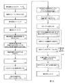
通常、身体構造の容積イメージングは多段階プロセスである。初めに生化学的薬剤、放射性薬剤及び/又は造影剤が投与され得る。次に、一組の所定のビューにおいて所定の位置、向き、及び持続時間で測定値が取られる。次に、データが分析されて身体構造のボリューム画像が再構成され、身体構造の画像が形成される。イメージングプロセスは順次プロセスであり、測定プロセスの完了後まで再構成画像の品質評価はない。得られた画像が低品質である場合、測定を繰り返さなければならず、患者に不都合が生じるとともにイメージングプロセスが非効率となる。 Usually, volumetric imaging of body structures is a multi-step process. Initially biochemical agents, radiopharmaceuticals and / or contrast agents may be administered. Next, measurements are taken at a predetermined position, orientation, and duration in a set of predetermined views. The data is then analyzed to reconstruct a volume image of the body structure and form an image of the body structure. The imaging process is a sequential process and there is no quality assessment of the reconstructed image until after the measurement process is completed. If the resulting image is of poor quality, the measurement must be repeated, causing inconvenience to the patient and making the imaging process inefficient.
容積スキャンは通常、コンピュータ断層撮影法を用いて線源の三次元画像を再構成するのに十分な情報を提供するため、複数の方向からの軌道上の検出器により実施される。検出器は典型的にはガントリーに取り付けられ、それにより構造支持が提供され、検出器が目的の物体の周りを周回する。検出器がシンチレーション検出器又はCZT検出器などの核医学検出器、例えば単一光子放出型コンピュータ断層撮影(SPECT)及び陽電子放出型断層撮影(PET)システム検出器である場合、検出器とイメージングされる物体との間に、放射線受容又は放射線が進む方向を制限するため使用されるコリメータが置かれる。典型的には、このコリメータは、鉛又はタングステンなどの高密度の高原子番号材料に多数の小さい孔が設けられた構成で作られる。放射線は、孔と平行な方向に進む場合は孔を通過し得るが、孔と平行でない方向に進む場合にはコリメータ材料に吸収される傾向があり得る。 Volume scans are typically performed with detectors on orbit from multiple directions to provide sufficient information to reconstruct a three-dimensional image of the source using computed tomography. The detector is typically attached to the gantry, thereby providing structural support and the detector orbits around the object of interest. If the detector is a nuclear medicine detector such as a scintillation detector or a CZT detector, such as a single photon emission computed tomography (SPECT) and positron emission tomography (PET) system detector, it is imaged with the detector. A collimator used to limit the direction of radiation reception or radiation travel is placed between the object and the object. Typically, this collimator is made with a configuration in which a large number of small holes are provided in a high density, high atomic number material such as lead or tungsten. Radiation can pass through the hole when traveling in a direction parallel to the hole, but can tend to be absorbed by the collimator material when traveling in a direction not parallel to the hole.
本発明の一部の実施形態において、患者の生体内ボリュームの機能的イメージングモダリティから得られた機能的画像に基づき所望の形状の物体(例えば、組織、神経、癌)の位置を決定するための方法及びシステムが提供される。任意選択で、機能的画像が解剖学的画像と組み合わされ、その組み合わされた画像に基づき神経組織の位置が決定される。任意選択で、所望の形状の物体は隣接組織のモデルを使用して検出される。 In some embodiments of the invention, for determining the location of an object of a desired shape (eg, tissue, nerve, cancer) based on a functional image obtained from a functional imaging modality of a patient's in vivo volume Methods and systems are provided. Optionally, the functional image is combined with the anatomical image and the position of the neural tissue is determined based on the combined image. Optionally, the desired shaped object is detected using a model of adjacent tissue.
本発明の一部の実施形態のある態様によれば、身体構造の画像に関する医用画像処理方法が提供され、本方法は、患者の体のある領域の解剖学的画像を再構成するため解剖学的データを受け取るステップであって、前記領域が、標的組織に接するか又はそれと離間した少なくとも1つの体内部位の一部分を含むステップと;患者の体の領域の少なくとも前記一部分をイメージングする機能的イメージングモダリティから機能的データを受け取るステップと;前記少なくとも1つの体内部位の壁の外側にあるゾーンに対応する少なくとも1つの画像マスクが生成されるように前記解剖学的画像を処理するステップと;前記標的組織を描出する機能的画像の再構成をガイドするため少なくとも1つの生成された画像マスクを機能的データと相関付けるステップと;再構成された機能的画像を提供するステップとを含む。 According to an aspect of some embodiments of the present invention, there is provided a medical image processing method relating to an image of a body structure, the method comprising an anatomy for reconstructing an anatomical image of a region of a patient's body. Functional data modality for imaging at least a portion of a region of a patient's body, wherein the region includes a portion of at least one body region that contacts or is spaced from the target tissue; Receiving functional data from; processing the anatomical image to generate at least one image mask corresponding to a zone outside the wall of the at least one body part; and the target tissue Correlate at least one generated image mask with the functional data to guide the reconstruction of the functional image rendering And providing the reconstructed functional images; step and that.
任意選択で、標的組織は神経組織である。 Optionally, the target tissue is neural tissue.
任意選択で、解剖学的データは解剖学的イメージングモダリティから得られる。 Optionally, anatomical data is obtained from an anatomical imaging modality.
任意選択で、少なくとも1つの画像マスクは、機能的データ内にレジスタリングされる強度活性を有する標的神経組織を含む少なくとも1つの体内部位の予め選択された解剖学的考慮事項に基づき生成される。 Optionally, the at least one image mask is generated based on preselected anatomical considerations of at least one in-vivo site that includes target neural tissue having intensity activity that is registered in functional data.
任意選択で、少なくとも1つの画像マスクは、少なくとも1つの体内部位の範囲内にある及び/又はそれに近接している標的神経組織の位置を定義するテンプレートに基づき生成される。 Optionally, the at least one image mask is generated based on a template that defines a location of target neural tissue that is within and / or proximate to at least one body site.
任意選択で、本方法は、標的神経組織を含まない対応する解剖学的データからの機能的データ読取り値に基づき画像マスクの形状を調整するステップをさらに含む。 Optionally, the method further comprises adjusting the shape of the image mask based on functional data readings from corresponding anatomical data that does not include the target neural tissue.
任意選択で、画像マスクは、放射性薬剤に対して種々のレベルの機能的感受性を有する標的神経構造の解剖学的位置に基づき生成される。 Optionally, the image mask is generated based on the anatomical location of the target neural structure having various levels of functional sensitivity to the radiopharmaceutical.
任意選択で、本方法は、標的神経組織の活性を示す測定値に基づき機能的データを正規化するステップをさらに含む。 Optionally, the method further comprises normalizing the functional data based on a measurement indicative of the activity of the target neural tissue.
任意選択で、本方法は、標的神経組織を含まない解剖学的領域から、標的神経組織を含まない領域の解剖学的データに基づきノイズを示す機能的データを除去するステップをさらに含む。 Optionally, the method further comprises removing functional data indicative of noise from an anatomical region not including the target neural tissue based on the anatomical data of the region not including the target neural tissue.
任意選択で、再構成された機能的画像は、標的神経構造が位置する領域及び/又は標的神経構造の正確な座標を含む。 Optionally, the reconstructed functional image includes the region where the target neural structure is located and / or the exact coordinates of the target neural structure.
任意選択で、1つは身体構造の壁用、もう1つは身体構造の壁の外側用の、2つの画像カッターであって、互いに異なる2つの画像カッターがある。 Optionally, there are two image cutters, one for the wall of the body structure and one for the outside of the wall of the body structure, and two different image cutters.
任意選択で、本方法は、標的神経を組織型と相関付けるステップをさらに含む。 Optionally, the method further comprises correlating the target nerve with a tissue type.
任意選択で、本方法は、少なくとも1つの所定の規則に基づき標的神経構造を同定するステップをさらに含む。 Optionally, the method further comprises identifying the target neural structure based on at least one predetermined rule.
任意選択で、少なくとも1つの所定の規則は、2D又は3Dサイズより大きいことを含む。 Optionally, the at least one predetermined rule includes greater than 2D or 3D size.
任意選択で、少なくとも1つの所定の規則は、少なくとも:臓器ボリューム、画像マスクの範囲内のうちの1つの全体にわたる分子活性レベルの平均値及び/又は標準偏差と比較される放射標識分子活性レベルを比較することを含む。 Optionally, the at least one predetermined rule comprises at least: radiolabeled molecular activity levels compared to at least: organ volume, average value and / or standard deviation of molecular activity levels over one of the image masks. Including comparing.
任意選択で、放射標識分子はメタヨードベンジルグアニジン(mIBG)である。 Optionally, the radiolabeled molecule is metaiodobenzylguanidine (mIBG).
任意選択で、本方法は、同定された標的神経構造に関する少なくとも1つのパラメータを計算するステップをさらに含む。 Optionally, the method further comprises calculating at least one parameter for the identified target neural structure.
任意選択で、画像マスクは、解剖学的画像のボリューム又はエリアを対応する機能的画像と相関付けるための、3Dボリューム又は2Dエリアのマッピングである。 Optionally, the image mask is a mapping of a 3D volume or 2D area to correlate an anatomical image volume or area with a corresponding functional image.
任意選択で、機能的イメージングモダリティは単一光子放出型コンピュータ断層撮影(SPECT)モダリティである。 Optionally, the functional imaging modality is a single photon emission computed tomography (SPECT) modality.
任意選択で、解剖学的イメージングモダリティは、コンピュータ断層撮影(CT)、3D超音波(US)、2D US、磁気共鳴画像法(MRI)を含む群から選択される。 Optionally, the anatomical imaging modality is selected from the group comprising computed tomography (CT), 3D ultrasound (US), 2D US, magnetic resonance imaging (MRI).
任意選択で、本方法は、解剖学的画像と機能的画像とのレジストレーションに画像マスクを適用するステップをさらに含む。 Optionally, the method further comprises applying an image mask to the registration of the anatomical image and the functional image.
任意選択で、本方法は、解剖学的画像を種々の領域にセグメンテーションするステップであって、それによりセグメンテーションされた領域内に種々のGPを検出するための画像マスクを生成するステップをさらに含む。 Optionally, the method further includes the step of segmenting the anatomical image into various regions, thereby generating an image mask for detecting various GPs within the segmented region.
任意選択で、本方法は、セグメントに基づき少なくとも1つの画像マスクを生成するステップをさらに含む。 Optionally, the method further comprises generating at least one image mask based on the segment.
任意選択で、神経を含む体内部位の構造の異なる部分に対応するように複数の異なる画像マスクセットが生成される。 Optionally, a plurality of different image mask sets are generated to correspond to different portions of the structure of the body part including the nerve.
任意選択で、異なるタイプの及び/又は異なる位置にある異なる神経構造を検出するため複数の画像マスクが生成される。 Optionally, multiple image masks are generated to detect different types and / or different neural structures at different locations.
任意選択で、本方法は、機能的データと相関付けられる少なくとも1つの生成された画像マスク内で機能活性を計算するステップと、計算された機能活性を正規化するステップとをさらに含む。 Optionally, the method further comprises calculating functional activity within at least one generated image mask correlated with the functional data and normalizing the calculated functional activity.
任意選択で、本方法は、治療及び診断の一方又は両方のため、再構成された機能的画像をナビゲーションシステムにレジスタリングするステップをさらに含む。 Optionally, the method further comprises registering the reconstructed functional image in a navigation system for one or both of therapy and diagnosis.
任意選択で、本方法は、神経構造間の相対的空間関係を示す同定された神経構造の空間的接続マップを生成するステップをさらに含む。 Optionally, the method further comprises generating a spatial connectivity map of the identified neural structures that indicates the relative spatial relationship between the neural structures.
任意選択で、本方法は、異なる画像マスクに基づき同定された神経構造を、少なくとも一部の同定された神経構造の単一のデータセットとなるように組み合わせるステップをさらに含む。 Optionally, the method further comprises combining the neural structures identified based on the different image masks into a single data set of at least some identified neural structures.
任意選択で、解剖学的画像は、神経の神経支配を受ける組織の構造を示す。 Optionally, the anatomical image shows the structure of the tissue undergoing innervation of the nerve.
任意選択で、機能的画像は、組織構造を神経支配する神経の機能活性を示す。 Optionally, the functional image shows the functional activity of nerves that innervate tissue structure.
任意選択で、画像マスクのサイズ及び形状は、組織構造を神経支配する標的神経を含むように生成される。 Optionally, the size and shape of the image mask is generated to include target nerves that innervate tissue structure.
任意選択で、相関付けるステップは、機能的画像内における標的神経組織の領域と一致するように少なくとも1つの画像マスクを位置決めするステップをさらに含む。 Optionally, the step of correlating further comprises positioning at least one image mask to match a region of target neural tissue in the functional image.
任意選択で、本方法が異なる時間フレームについて繰り返され、単一の再構成画像が生成される。 Optionally, the method is repeated for different time frames to generate a single reconstructed image.
任意選択で、解剖学的画像が周期性の生理学的過程の間に入手され、ここで生理学的過程の異なる段階の間に入手された画像について異なる時空間画像マスクが生成され、異なる時空間画像マスクは組織の同じ位置に対応するように生理学的過程と同期される。 Optionally, anatomical images are acquired during a periodic physiological process, where different spatiotemporal image masks are generated for images acquired during different stages of the physiological process, and different spatiotemporal images are generated. The mask is synchronized with the physiological process to correspond to the same location in the tissue.
任意選択で、周期性の生理学的過程の間に入手された解剖学的画像はレジスタリングされ、モーフィングされて、単一の画像マスクセットが生成される。 Optionally, anatomical images obtained during a periodic physiological process are registered and morphed to generate a single image mask set.
任意選択で、中空臓器に関する画像マスクのサイズは臓器壁の厚さに基づき選択される。 Optionally, the size of the image mask for the hollow organ is selected based on the thickness of the organ wall.
任意選択で、本方法は組織のアブレーション治療の前に実施され、それにより組織の位置が同定される。 Optionally, the method is performed prior to tissue ablation treatment, thereby identifying the location of the tissue.
本発明の一部の実施形態のある態様によれば、心臓のANSの神経組織の画像に関する医用画像処理方法が提供され、この方法は、ANSの神経支配を受ける心臓構造の解剖学的画像を再構成するため解剖学的画像データを受け取るステップと;ANSの神経支配を受ける心臓構造を少なくともイメージングする機能的イメージングモダリティから機能的データを受け取るステップと;解剖学的画像を処理することにより少なくとも1つの画像マスクを選択するステップであって、少なくとも1つの画像マスクが神経組織を含む心腔壁の寸法に対応するステップと;GPを描出する機能的画像の再構成をガイドするため機能的データに少なくとも1つの選択された画像マスクを適用するステップと;再構成された機能的画像を提供するステップとを含む。 According to an aspect of some embodiments of the present invention, there is provided a medical image processing method for an image of ANS neural tissue of the heart, the method comprising an anatomical image of a cardiac structure subject to ANS innervation. Receiving anatomical image data for reconstruction; receiving functional data from a functional imaging modality that at least images a cardiac structure subject to ANS innervation; and at least one by processing the anatomical image Selecting one image mask, wherein the at least one image mask corresponds to a dimension of a heart chamber wall containing neural tissue; and functional data to guide reconstruction of a functional image depicting a GP Applying at least one selected image mask; and providing a reconstructed functional image. Including the door.
任意選択で、神経組織はGPである。 Optionally, the neural tissue is GP.
任意選択で、少なくとも1つの画像マスクは心臓壁腔と比較して過大である。 Optionally, the at least one image mask is excessive compared to the heart wall cavity.
任意選択で、少なくとも1つの画像マスクは、機能的データ内にレジスタリングされる強度活性を有する標的神経組織を含む心臓の予め選択された解剖学的領域に基づき生成される。 Optionally, the at least one image mask is generated based on a preselected anatomical region of the heart that includes target neural tissue having intensity activity that is registered in functional data.
任意選択で、少なくとも1つの画像マスクは、心腔壁に近接したGPの位置を定義するテンプレートに基づき生成される。 Optionally, the at least one image mask is generated based on a template that defines the position of the GP proximate the heart chamber wall.
任意選択で、少なくとも1つの画像マスクは、心腔壁内のGPの位置を定義するテンプレートに基づき生成される。 Optionally, the at least one image mask is generated based on a template that defines the position of the GP within the heart chamber wall.
任意選択で、少なくとも1つの画像マスクは、心腔壁から約2mm超に位置するGPの位置を定義するテンプレートに基づき生成される。 Optionally, the at least one image mask is generated based on a template that defines the position of the GP located more than about 2 mm from the heart chamber wall.
任意選択で、本方法は、GPを含まない血液腔及び/又は血液管の対応する解剖学的データからの機能的データ読取り値に基づき画像マスクの形状を調整するステップをさらに含む。 Optionally, the method further comprises adjusting the shape of the image mask based on functional data readings from corresponding anatomical data of blood cavities and / or blood tubes that do not contain GP.
任意選択で、本方法は、血液が充満した心臓の腔及び/又は管の内部から解剖学的データに基づきノイズを示す機能的データを削除するステップをさらに含む。 Optionally, the method further comprises deleting functional data indicative of noise from the interior of the blood-filled heart cavity and / or vessel based on anatomical data.
任意選択で、機能的イメージングモダリティがSPECTであり、且つ解剖学的イメージングモダリティがCT及びMRIの少なくとも一方である。 Optionally, the functional imaging modality is SPECT and the anatomical imaging modality is at least one of CT and MRI.
任意選択で、解剖学的画像は心周期の間に入手され、ここで心周期の間に入手された少なくとも一部の画像に異なる時空間画像マスクが選択され、異なる時空間画像マスクは、心臓の同じ位置に対応するように心周期と同期される。 Optionally, anatomical images are acquired during the cardiac cycle, where different spatiotemporal image masks are selected for at least some images acquired during the cardiac cycle, and the different spatiotemporal image masks are Are synchronized with the cardiac cycle to correspond to the same positions of
任意選択で、解剖学的画像は、拡張末期容積画像及び収縮末期容積画像から構成される平均画像である。 Optionally, the anatomical image is an average image composed of an end diastolic volume image and an end systolic volume image.
任意選択で、本方法は、解剖学的画像を心腔の壁にセグメンテーションするステップをさらに含む。 Optionally, the method further comprises segmenting the anatomical image into the heart chamber wall.
任意選択で、本方法は、心腔壁セグメントに基づき少なくとも1つの画像マスクを選択するステップをさらに含む。 Optionally, the method further comprises selecting at least one image mask based on the heart chamber wall segment.
任意選択で、心外膜及び心筋外組織に対応するように第1の画像マスクセットが選択され、及び心筋に対応するように第2の画像マスクセットが選択される。 Optionally, a first image mask set is selected to correspond to the epicardium and extramyocardial tissue, and a second image mask set is selected to correspond to the myocardium.
任意選択で、本方法は、相関付けられた画像マスク内での機能活性を計算するステップと、計算された活性を正規化してGPを同定するステップとをさらに含む。 Optionally, the method further comprises calculating functional activity within the correlated image mask and normalizing the calculated activity to identify the GP.
任意選択で、心臓のボリューム内にある全ての画像マスクについて機能活性が計算される。 Optionally, functional activity is calculated for all image masks within the heart volume.
任意選択で、本方法は、GPが所定のサイズより大きいことを含む少なくとも1つの所定の規則に基づきGPを同定するステップをさらに含む。 Optionally, the method further comprises identifying the GP based on at least one predetermined rule including that the GP is greater than a predetermined size.
任意選択で、心外膜内に位置する心外膜GPと、心筋内に位置する心筋GPとで所定のサイズは異なる。 Optionally, the predetermined size is different between the epicardial GP located in the epicardium and the myocardial GP located in the myocardium.
任意選択で、本方法は、計算された活性が所定の閾値を上回ることを含む少なくとも1つの所定の規則に基づきGPを同定するステップをさらに含む。 Optionally, the method further comprises identifying the GP based on at least one predetermined rule that includes the calculated activity exceeding a predetermined threshold.
任意選択で、所定の閾値は、画像マスク内の平均活性計算値を画像マスク内の活性の標準偏差計算値の所定倍数だけ上回る値に基づき、活性領域を取り囲む隣接活性計算値は、活性領域の活性の半分未満である。 Optionally, the predetermined threshold is based on a value that exceeds the average active calculated value in the image mask by a predetermined multiple of the standard deviation calculated for activity in the image mask, and the adjacent active calculated value surrounding the active region is Less than half of the activity.
任意選択で、本方法は、同定されたGPに関する少なくとも1つのパラメータを計算するステップをさらに含む。 Optionally, the method further comprises calculating at least one parameter for the identified GP.
任意選択で、少なくとも1つのパラメータは、平均サイズ、比活性、パワースペクトル、正規化されたパワースペクトル及びGP接続マップ、所定面積当たりのGPの数のうちの1つ以上から選択される。 Optionally, the at least one parameter is selected from one or more of average size, specific activity, power spectrum, normalized power spectrum and GP connection map, number of GPs per predetermined area.
任意選択で、心周期の少なくとも1つの画像について少なくとも1つのパラメータが計算される。 Optionally, at least one parameter is calculated for at least one image of the cardiac cycle.
任意選択で、本方法は、少なくとも1つのパラメータの経時的変化を同定するステップをさらに含む。 Optionally, the method further comprises identifying a change in at least one parameter over time.
任意選択で、本方法は、同定されたGP、心周期の複数のフレームの少なくとも1つの画像を表示するステップをさらに含む。 Optionally, the method further comprises displaying at least one image of a plurality of frames of the identified GP, cardiac cycle.
任意選択で、本方法は、同定されたGPを治療用ナビゲーションシステムにレジスタリングするステップをさらに含む。 Optionally, the method further comprises registering the identified GP with a therapeutic navigation system.
本発明の一部の実施形態のある態様によれば、1つ以上のANS成分の画像に関する医用画像処理方法であって、本方法のステップを実行するようにプログラムされた少なくとも1つのモジュールによって実行される方法が提供され、この方法は、患者の体のある領域の解剖学的画像を再構成するため解剖学的イメージングモダリティから解剖学的データを受け取るステップであって、前記領域が、ANS成分に接するか又はそれを含む少なくとも1つの体内部位の一部分を含むステップと;患者の体の領域の少なくとも前記一部分をイメージングした機能的イメージングモダリティから機能的データを受け取るステップと;前記少なくとも1つの体内部位の寸法に対応する寸法を有する少なくとも1つの画像マスクが生成されるように前記解剖学的画像を処理するステップと;前記ANS成分を描出する機能的画像を再構成するため機能的データに少なくとも1つの生成された画像マスクを適用するステップと;機能的画像において1つ以上のANS成分を同定するステップとを含む。 In accordance with an aspect of some embodiments of the present invention, a medical image processing method for images of one or more ANS components, performed by at least one module programmed to perform the steps of the method Receiving a anatomical data from an anatomical imaging modality to reconstruct an anatomical image of a region of a patient's body, the region comprising an ANS component Receiving a functional data from a functional imaging modality that has imaged at least a portion of a region of a patient's body; and receiving said functional data from said functional imaging modality; To generate at least one image mask having a dimension corresponding to the dimension of Processing an autopsy image; applying at least one generated image mask to the functional data to reconstruct a functional image depicting the ANS component; and one or more in the functional image Identifying an ANS component.
本発明の一部の実施形態のある態様によれば、心臓のANSのGPの画像に関する医用画像処理方法であって、本方法のステップを実行するようにプログラムされた少なくとも1つのモジュールによって実行される方法が提供され、この方法は、ANSの神経支配を受ける心臓構造の解剖学的画像を再構成するため解剖学的イメージングモダリティから解剖学的画像データを受け取るステップと;ANSの神経支配を受ける心臓構造を少なくともイメージングする機能的イメージングモダリティから機能的データを受け取るステップと;解剖学的画像を処理することにより少なくとも1つの画像マスクを生成するステップであって、少なくとも1つの画像マスクがGPを含む心腔壁の寸法に対応するステップと;心臓のANSの1つ以上のGPの位置を決定するため機能的データに少なくとも1つの選択された画像マスクを適用するステップとを含む。 According to an aspect of some embodiments of the present invention, there is provided a medical image processing method for ANS GP images of the heart, performed by at least one module programmed to perform the steps of the method. Receiving anatomical image data from an anatomical imaging modality to reconstruct an anatomical image of a cardiac structure subject to ANS innervation; receiving the ANS innervation; Receiving functional data from a functional imaging modality that at least images the cardiac structure; generating at least one image mask by processing the anatomical image, wherein the at least one image mask includes GP Corresponding to the dimensions of the heart chamber wall; one or more Gs of the ANS of the heart Situated in functional data for determining the including the step of applying at least one selected image mask.
本発明の一部の実施形態のある態様によれば、機能的イメージングモダリティを使用して心臓治療をガイドする方法が提供され、この方法は、心臓を含む患者の生体内ボリュームをイメージングする機能的イメージングモダリティから機能的イメージングモダリティデータを提供するステップであって、患者は、心臓の自律神経系(ANS)による神経組織内取込みを有する造影剤を注入されており、ANSは少なくとも1つのGPを含む、ステップと;機能的イメージングモダリティデータに基づき、心臓を神経支配する少なくとも1つのGPの位置を決定するステップと;位置が決定された少なくとも1つのGPを提供するステップとを含む。 According to certain aspects of some embodiments of the present invention, there is provided a method for guiding cardiac therapy using a functional imaging modality, the method comprising functionally imaging an in-vivo volume of a patient including a heart. Providing functional imaging modality data from an imaging modality, wherein the patient has been infused with a contrast agent having neural tissue uptake by the cardiac autonomic nervous system (ANS), the ANS comprising at least one GP Determining the position of at least one GP that innervates the heart based on the functional imaging modality data; and providing at least one GP whose position has been determined.
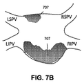
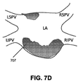
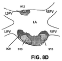
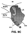
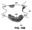
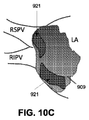
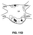
任意選択で、ANSは、左上GP(SLGP)、左下GP(ILGP)、右前GP(ARGP)、右下GP(IRGP)、及びマーシャルGPのうちの1つ以上を含む少なくとも1つのGPを含む。 Optionally, the ANS includes at least one GP including one or more of an upper left GP (SLGP), a lower left GP (ILGP), a right front GP (ARGP), a lower right GP (IRGP), and a Marshall GP.
任意選択で、ANSは、左上GP(SLGP)、左下GP(ILGP)、右前GP(ARGP)、右下GP(IRGP)、及びマーシャルGPのうちの2つ又は3つ又はそれ以上からの2つ、3つ又はそれ以上のGPを含む。 Optionally, the ANS is two from two or three or more of upper left GP (SLGP), lower left GP (ILGP), right front GP (ARGP), lower right GP (IRGP), and Marshall GP. Includes three or more GPs.
任意選択で、本方法は、位置が決定された少なくとも1つのGPの不適切な活性に基づき心疾患を治療するため、位置が決定された少なくとも1つのGPのアブレーション用システムをセットアップするステップをさらに含む。 Optionally, the method further comprises the step of setting up a position ablation system of at least one GP determined to treat heart disease based on inappropriate activity of the at least one GP determined position. Including.
任意選択で、心疾患は心房細動を含む。 Optionally, the heart disease includes atrial fibrillation.
任意選択で、治療用又は他の診断用EPカテーテルに対するGPの位置を表示するため、位置が決定されたGPの座標が生体内ナビゲーションシステムにロードされる。 Optionally, the coordinates of the determined GP are loaded into the in-vivo navigation system to display the position of the GP relative to the therapeutic or other diagnostic EP catheter.
任意選択で、CARTO(登録商標)システムの治療用カテーテルに対するGPの位置を表示するため、位置が決定されたGPの座標がCARTO(登録商標)システムにロードされる。 Optionally, the coordinates of the GP whose position has been determined are loaded into the CARTO® system to display the position of the GP relative to the CARTO® system treatment catheter.
任意選択で、本方法は、CARTO(登録商標)システムに基づき患者体内でカテーテルをナビゲートするステップをさらに含む。 Optionally, the method further comprises navigating the catheter within the patient based on the CARTO® system.
任意選択で、本方法は、CARTO(登録商標)システムに基づきGPアブレーションの治療ポイントを機能的に検証するステップをさらに含む。 Optionally, the method further comprises functionally verifying a GP ablation treatment point based on the CARTO® system.
任意選択で、本方法は、位置が決定されたGPをCARTO(登録商標)システムでアブレーションするステップをさらに含む。 Optionally, the method further comprises ablating the position-determined GP with a CARTO® system.
任意選択で、本方法は、GPのアブレーションをCARTO(登録商標)システムで確認するステップをさらに含む。 Optionally, the method further comprises the step of confirming GP ablation with a CARTO® system.
任意選択で、位置を決定するステップは、機能的イメージングモダリティデータに基づき心臓の脂肪パッド又は他の周囲組織において少なくとも1つのGPの位置を決定するステップを含む。任意選択で、システムをセットアップするステップは、周囲の脂肪パッドの大部分をアブレーションすることなしに脂肪パッド内の少なくとも1つのGPをアブレーションするためシステムをセットアップするステップを含む。 Optionally, determining the location includes determining the location of at least one GP in the cardiac fat pad or other surrounding tissue based on the functional imaging modality data. Optionally, setting up the system includes setting up the system to ablate at least one GP in the fat pad without ablating most of the surrounding fat pad.
任意選択で、本方法は、心臓を含む患者の生体内ボリュームをイメージングする解剖学的画像モダリティから解剖学的イメージングモダリティデータを取得するステップをさらに含み、ここで位置を決定するステップは、機能的イメージングモダリティデータ及び解剖学的イメージングモダリティデータのレジストレーションに基づき心臓の生体内ボリュームにおける又は生体内ボリュームに隣接する少なくとも1つのGPの位置を決定するステップを含む。 Optionally, the method further comprises obtaining anatomical imaging modality data from an anatomical image modality that images a patient's in-vivo volume, including the heart, wherein determining the position comprises functionally Determining a position of at least one GP in or adjacent to the in-vivo volume of the heart based on registration of the imaging modality data and the anatomical imaging modality data.
任意選択で、本方法は、位置が決定された少なくとも1つのGPを解剖学的イメージングモダリティデータ上にマーキングするステップをさらに含む。 Optionally, the method further comprises marking at least one GP whose position has been determined on the anatomical imaging modality data.
任意選択で、解剖学的イメージングモダリティデータが蛍光透視による治療手技中にリアルタイムで取得され、位置を決定するステップが、CTによる治療手技の前に及び/又はその最中にリアルタイムで実施され、及び少なくとも1つのGPの位置が、治療手技を実施している操作者に提示される。 Optionally, anatomical imaging modality data is acquired in real time during a fluoroscopic treatment procedure, and the position determining step is performed in real time before and / or during the CT treatment procedure, and The location of at least one GP is presented to the operator performing the treatment procedure.
任意選択で、本方法は、ANSシナプス及びGPの一方又は両方の分布及び/又は活性を含むANSマップを生成するステップと、表示のためANSマップを提供するステップとをさらに含む。 Optionally, the method further includes generating an ANS map that includes the distribution and / or activity of one or both of ANS synapses and GPs, and providing the ANS map for display.
任意選択で、ANSマップは、再構成された解剖学的画像及びCARTO(登録商標)マッピング画像と同じスペース内において、心臓内の治療プローブ又はイメージングプローブを含む心臓の再構成された解剖学的画像上にオーバーレイされる。 Optionally, the ANS map is a reconstructed anatomical image of the heart that includes a treatment probe or imaging probe in the heart in the same space as the reconstructed anatomical image and the CARTO® mapping image. Overlaid on top.
任意選択で、位置を決定するステップは、連続性分裂心房電位(CFAE)部位と収縮力(CF)部位との間の共通部分を同定するステップを含み、ガイドするステップは、この共通部分のアブレーションをガイドするステップを含む。 Optionally, determining the position includes identifying the intersection between a continuous split atrial potential (CFAE) site and a contractile force (CF) site, and the step of guiding includes ablating the intersection. Including the step of guiding.
任意選択で、位置を決定するステップは、連続性分裂心房電位(CFAE)部位とドミナント周波数(DF)部位との間の共通部分を同定するステップを含み、ガイドするステップは、この共通部分のアブレーションをガイドするステップを含む。 Optionally, determining the location includes identifying a common part between a continuous split atrial potential (CFAE) site and a dominant frequency (DF) site, and the step of guiding comprises ablating the common part. Including the step of guiding.
任意選択で、位置を決定するステップは、連続性分裂心房電位(CFAE)部位と少なくとも1つのGPとの間の共通部分を同定するステップを含み、ガイドするステップは、この共通部分のアブレーションをガイドするステップを含む。 Optionally, the step of determining includes identifying a common part between a continuous split atrial potential (CFAE) site and at least one GP, and the step of guiding guides the ablation of this common part. Including the steps of:
任意選択で、位置を決定するステップは、連続性分裂心房電位(CFAE)部位とドミナント周波数(DF)と少なくとも1つのGPとの間の共通部分を同定するステップを含み、ガイドするステップは、この共通部分のアブレーションをガイドするステップを含む。 Optionally, determining the location includes identifying the intersection between a continuous split atrial potential (CFAE) site, a dominant frequency (DF) and at least one GP, and the step of guiding includes Guiding the ablation of the common part.
任意選択で、位置を決定するステップは、連続性分裂心房電位(CFAE)部位と収縮力(CF)部位と少なくとも1つのGPとの間の共通部分を同定するステップを含み、ガイドするステップは、この共通部分のアブレーションをガイドするステップを含む。 Optionally, determining the position includes identifying the intersection between a continuous split atrial potential (CFAE) site, a contractile force (CF) site and at least one GP, and the step of guiding comprises Guiding the ablation of this common part.
任意選択で、位置を決定するステップは、少なくとも1つのGPをイメージングするステップと、位置が決定されたGPの周りをマッピングしてGPの位置を検証するステップとを含む。 Optionally, determining the position includes imaging at least one GP and mapping around the determined GP to verify the position of the GP.
任意選択で、本方法は、患者が心臓ANSの不適切な活性を受けているという仮説に基づき患者を選択するステップをさらに含む。 Optionally, the method further comprises selecting a patient based on a hypothesis that the patient is experiencing inappropriate activity of the heart ANS.
任意選択で、取得するステップは、少なくとも1つの心周期の間にデータ複数フレームを含むように取得するステップと、単一画像を再構成するステップとを含む。 Optionally, the acquiring step includes acquiring to include multiple frames of data during at least one cardiac cycle and reconstructing a single image.
任意選択で、本方法は、心臓に対するアブレーションの効果をモニタするステップをさらに含む。 Optionally, the method further comprises monitoring the effect of ablation on the heart.
任意選択で、本方法は、生成されたANSモデルに基づきアブレーションの効果を確認するステップをさらに含む。 Optionally, the method further comprises the step of confirming the ablation effect based on the generated ANS model.
本発明の一部の実施形態のある態様によれば、患者の心臓の画像内でANS組織を同定するシステムが提供され、このシステムは、心臓を含む患者の生体内ボリュームをイメージングする機能的イメージングモダリティから機能的イメージングモダリティデータを受け取るモジュールであって、患者は、心臓の自律神経系(ANS)による神経組織内取込みを有する造影剤を注入されており、ANSは少なくとも1つのGPを含む、モジュールと;心臓を含む患者の生体内ボリュームをイメージングする解剖学的イメージングモダリティから解剖学的イメージングモダリティデータを受け取るモジュールと;機能的イメージングモダリティデータに基づき、心臓を神経支配する少なくとも1つのGPの位置を決定するモジュールと;位置が決定された少なくとも1つのGPを解剖学的イメージングデータ上に位置付けるモジュールとを含む。 According to an aspect of some embodiments of the present invention, a system is provided for identifying ANS tissue in an image of a patient's heart, the system imaging functional patient volume including the heart. A module for receiving functional imaging modality data from a modality, wherein the patient has been injected with a contrast agent having an uptake in neural tissue by the autonomic nervous system (ANS) of the heart, and the ANS includes at least one GP A module for receiving anatomical imaging modality data from an anatomical imaging modality that images a patient's in-vivo volume including the heart; and based on the functional imaging modality data, the location of at least one GP that innervates the heart Module to determine; position determined Have been and a module positioned on the anatomical imaging data at least one GP.
任意選択で、ANSは、左上GP(SLGP)、左下GP(ILGP)、右前GP(ARGP)、右下GP(IRGP)、及びマーシャルGPのうちの1つ以上を含む少なくとも1つのGPを含む。 Optionally, the ANS includes at least one GP including one or more of an upper left GP (SLGP), a lower left GP (ILGP), a right front GP (ARGP), a lower right GP (IRGP), and a Marshall GP.
任意選択で、ANSは、左上GP(SLGP)、左下GP(ILGP)、右前GP(ARGP)、右下GP(IRGP)、及びマーシャルGPのうちの2つ又は3つ又はそれ以上からの2つ、3つ又はそれ以上のGPを含む。 Optionally, the ANS is two from two or three or more of upper left GP (SLGP), lower left GP (ILGP), right front GP (ARGP), lower right GP (IRGP), and Marshall GP. Includes three or more GPs.
任意選択で、解剖学的イメージングモダリティデータは治療手技の前及び/又はその最中に受け取られる。 Optionally, anatomical imaging modality data is received before and / or during the treatment procedure.
任意選択で、本システムはカテーテル心臓ナビゲーションシステムをさらに含み、カテーテル心臓ナビゲーションシステムは、位置決定された神経組織を受け取り表示することにより、神経組織のアブレーションのため心臓内で生体内治療プローブをガイドする。 Optionally, the system further includes a catheter cardiac navigation system that guides the in vivo treatment probe in the heart for ablation of neural tissue by receiving and displaying the localized neural tissue. .
任意選択で、カテーテル心臓ナビゲーションシステムはCARTO(登録商標)である。 Optionally, the catheter heart navigation system is CARTO®.
任意選択で、カテーテル心臓ナビゲーションシステムは3D電気生理学的(EP)システムである。 Optionally, the catheter heart navigation system is a 3D electrophysiological (EP) system.
任意選択で、本システムは、心臓内での神経組織のアブレーション用生体内治療プローブをさらに含む。 Optionally, the system further includes an in vivo treatment probe for ablation of neural tissue in the heart.
任意選択で、生体内治療プローブは、高周波(RF)治療プローブ、冷凍外科手術治療プローブ、及び毒素又は薬物を注入するプローブのうちの少なくとも1つである。 Optionally, the in-vivo therapy probe is at least one of a radio frequency (RF) therapy probe, a cryosurgery therapy probe, and a probe for injecting a toxin or drug.
任意選択で、本システムは、イメージングされた神経組織の分布を1つ以上の予想分布セットと比較し、且つ比較に基づき異常なシナプス分布及び/又は活性を検出するための診断モジュールをさらに含む。 Optionally, the system further includes a diagnostic module for comparing the distribution of the imaged neural tissue with one or more expected distribution sets and detecting an abnormal synaptic distribution and / or activity based on the comparison.
任意選択で、本システムは、イメージングされた神経組織の分布の経時的変化をトラッキングするトラッキングモジュールをさらに含む。 Optionally, the system further includes a tracking module that tracks changes in the distribution of the imaged neural tissue over time.
任意選択で、本システムは、生成されたANSモデル及び診断のうちの少なくとも一方を保存するリポジトリをさらに含む。 Optionally, the system further includes a repository that stores at least one of the generated ANS model and diagnostics.
任意選択で、本システムは、機能的画像の測定された取込みに基づきアブレーション手技の成功の予測を推定するモジュールをさらに含む。 Optionally, the system further includes a module that estimates a prediction of the success of the ablation procedure based on the measured capture of the functional image.
任意選択で、本システムは、使用者から手動入力を受け取るユーザ入力要素と、受け取った手動入力に基づき、位置決定された神経組織に注釈を付ける治療計画モジュールとをさらに含む。 Optionally, the system further includes a user input element that receives manual input from the user and a treatment planning module that annotates the localized neural tissue based on the received manual input.
任意選択で、本システムは、特定の生体内エリアにおける神経組織を刺激すること、及び刺激に応答した1つ以上の神経応答を同定することのうちの少なくとも一方のための機能検証モジュールをさらに含む。 Optionally, the system further includes a functional verification module for at least one of stimulating neural tissue in a particular in-vivo area and identifying one or more neural responses in response to the stimulation. .
任意選択で、本システムは、生成されたANSモデルに基づき治療後の神経組織の刺激の効果を治療前の神経組織の刺激の効果と比較して治療を確認するモジュールをさらに含む。 Optionally, the system further includes a module that compares the effect of stimulation of neural tissue after treatment with the effect of stimulation of neural tissue before treatment based on the generated ANS model to confirm the treatment.
任意選択で、本システムのモジュールは分散している。 Optionally, the modules of the system are distributed.
本発明の一部の実施形態のある態様によれば、患者の心臓の画像内においてANS成分を同定するためのシステムが提供され、このシステムは、心臓を含む患者の生体内ボリュームをイメージングする機能的イメージングモダリティから機能的イメージングモダリティデータを受け取るため(患者は、心臓の自律神経系(ANS)による神経組織内取込みを有する造影剤を注入されており、ANSは、左上GP(SLGP)、左下GP(ILGP)、右前GP(ARGP)、右下GP(IRGP)、及びマーシャルGPのうちの1つ以上を含む少なくとも1つのGPを含む);心臓を含む患者の生体内ボリュームをイメージングする解剖学的イメージングモダリティから解剖学的イメージングモダリティデータを受け取るため;及び機能的イメージングモダリティデータ及び解剖学的イメージングモダリティデータに基づき心臓の生体内ボリュームにおいて少なくとも1つのGPの位置を決定するための少なくとも1つのモジュールを含む。 According to an aspect of some embodiments of the present invention, there is provided a system for identifying an ANS component in an image of a patient's heart, the system imaging a patient's in-vivo volume that includes the heart To receive functional imaging modality data from a functional imaging modality (the patient has been injected with a contrast agent having neural tissue uptake by the cardiac autonomic nervous system (ANS), the ANS is the upper left GP (SLGP), the lower left GP (Including at least one GP including one or more of (ILGP), right front GP (ARGP), lower right GP (IRGP), and Marshall GP)); anatomical imaging in vivo volume of patient including heart Receiving anatomical imaging modality data from the imaging modality; In vivo volume of the heart based on over managing modality data and anatomic imaging modalities data including at least one module for determining the position of at least one GP.
本発明の一部の実施形態のある態様によれば、神経組織をイメージングする方法が提供され、この方法は、身体部位を有する患者の生体内ボリュームをイメージングする機能的イメージングモダリティから機能的イメージングモダリティデータを取得するステップであって、患者は、自律神経系(ANS)による神経組織内取込みを有する造影剤を注入されている、ステップと;機能的イメージングモダリティデータに基づき生体内ボリュームにおける神経組織の位置を決定するステップとを含む。 According to certain aspects of some embodiments of the present invention, there is provided a method of imaging neural tissue, the method comprising a functional imaging modality that images a patient's in vivo volume having a body part. Acquiring data, the patient being injected with a contrast agent having an uptake in neural tissue by the autonomic nervous system (ANS); and the neural tissue in the in vivo volume based on functional imaging modality data Determining a position.
任意選択で、本方法は、活性レベルを有する位置決定された神経組織に基づきANSの画像を生成するステップをさらに含む。 Optionally, the method further includes generating an image of the ANS based on the localized neural tissue having an activity level.
任意選択で、画像は、位置決定された神経組織の活性レベルを示す。 Optionally, the image shows the level of neural tissue activity localized.
任意選択で、本方法は、位置決定された神経組織の不適切な活性に基づき疾患を治療するための位置決定された神経組織の治療用システムをセットアップするステップをさらに含む。 Optionally, the method further comprises setting up a system for treating a localized neural tissue for treating a disease based on the inappropriate activity of the localized neural tissue.
任意選択で、本方法は、身体部位を含む患者の生体内ボリュームをイメージングする解剖学的画像モダリティから解剖学的イメージングモダリティデータを取得するステップをさらに含み、ここで位置を決定するステップは、機能的イメージングモダリティデータ及び解剖学的イメージングモダリティデータに基づき心臓の生体内ボリュームにおける神経組織の位置を決定するステップを含む。 Optionally, the method further comprises obtaining anatomical imaging modality data from an anatomical imaging modality that images a patient's in vivo volume including a body part, wherein determining the location comprises Determining the location of neural tissue in the in-vivo volume of the heart based on the dynamic imaging modality data and the anatomical imaging modality data.
任意選択で、本方法は、位置決定された神経組織を解剖学的イメージングモダリティデータ上に位置付けるステップをさらに含む。 Optionally, the method further comprises positioning the located neural tissue on the anatomical imaging modality data.
任意選択で、解剖学的イメージングモダリティデータが治療手技中にリアルタイムで取得され、位置を決定するステップが治療手技の前に及び/又はその最中にリアルタイムで実施され、及び神経組織の位置が治療手技を実施している操作者に提示される。 Optionally, anatomical imaging modality data is acquired in real time during the treatment procedure, the position determining step is performed in real time before and / or during the treatment procedure, and the position of the neural tissue is treated Presented to the operator performing the procedure.
任意選択で、位置を決定するステップは、最大直径が1〜20mmのサイズの、ANSの少なくとも1つの神経節叢(GP)の位置を決定するステップを含む。 Optionally, determining the position includes determining the position of at least one ganglion plexus (GP) of the ANS having a maximum diameter of 1-20 mm in size.
任意選択で、位置を決定するステップは、最大直径が1〜20mmのサイズの、ANSの少なくとも2つの神経節叢(GP)の位置を決定するステップを含む。 Optionally, determining the position includes determining the position of at least two ganglion plexuses (GPs) of the ANS having a maximum diameter of 1-20 mm.
任意選択で、本方法は、ANSシナプス及びGPの一方又は両方の分布及び/又は活性を含むANSマップを生成するステップと、表示のためANSマップを提供するステップとをさらに含む。 Optionally, the method further includes generating an ANS map that includes the distribution and / or activity of one or both of ANS synapses and GPs, and providing the ANS map for display.
任意選択で、本方法は、ANSマップを、神経組織を含む臓器の画像表現とオーバーレイするステップをさらに含む。 Optionally, the method further comprises overlaying the ANS map with an image representation of an organ including neural tissue.
任意選択で、本方法は、患者を診断するステップをさらに含み、診断するステップが、臓器に関するシナプス及び/又は神経節の活性及び分布の一方又は両方に基づき、臓器に対するANSの効果を推定するステップを含む。 Optionally, the method further comprises the step of diagnosing the patient, the step of diagnosing estimating the effect of the ANS on the organ based on one or both of synaptic and / or ganglion activity and distribution with respect to the organ. including.
任意選択で、本方法は、ANSをその画像と連動して刺激するステップと、刺激及びイメージングに基づき求心性活性と遠心性活性とを区別するステップとをさらに含む。 Optionally, the method further comprises stimulating the ANS in conjunction with the image and distinguishing between afferent activity and efferent activity based on stimulation and imaging.
任意選択で、本方法は、治療前、治療中及び/又は治療後に、臓器に関するシナプス及び/又は神経節の活性及び分布の一方又は両方に基づき自律神経系及び/又は臓器の効果又は効果及び/又は応答の変化を推定するステップをさらに含む。 Optionally, the method comprises an autonomic nervous system and / or organ effect or effect based on one or both of synapse and / or ganglion activity and distribution with respect to the organ before, during and / or after treatment. Alternatively, the method further includes estimating a change in response.
任意選択で、本方法は、臓器に関連するデータに基づき神経組織シナプス及び/又は神経支配を同定する臓器の構造のモデルに従い機能的イメージングモダリティデータを空間的位置に割り当てるステップをさらに含む。 Optionally, the method further comprises assigning functional imaging modality data to the spatial location according to a model of the structure of the organ that identifies neural tissue synapses and / or innervation based on the data associated with the organ.
任意選択で、本方法は、参照動態学的挙動の生体内ボリュームにおいて少なくとも1つの領域をマッピングするマッピング関数を提供するステップと、生体内ボリュームにおける神経組織の位置を決定するため機能的データにマッピング関数を適用するステップとをさらに含む。 Optionally, the method provides a mapping function that maps at least one region in the in vivo volume of the reference kinetic behavior, and maps to functional data to determine the location of neural tissue in the in vivo volume. Applying the function.
任意選択で、本方法は、参照取込み値に関連する神経応答を惹起するため患者の生体内ボリュームにおける神経組織を刺激するステップと、神経応答中に、生体内ボリュームをイメージングする機能的モダリティから機能的データを取得するステップと、参照取込み値に従い生体内ボリュームにおける神経組織の位置を特定するステップとをさらに含む。 Optionally, the method functions from stimulating neural tissue in the patient's in vivo volume to elicit a neural response associated with the reference uptake value, and from a functional modality that images the in vivo volume during the neural response. Further comprising obtaining the target data and determining the position of the neural tissue in the in vivo volume according to the reference uptake value.
任意選択で、本方法は、患者の生体内ボリュームをイメージングする解剖学的イメージングモダリティから解剖学的データを取得するステップと、機能的データ及び解剖学的データの両方に基づき生体内ボリュームにおける標的神経組織の位置を特定するステップとをさらに含む。 Optionally, the method includes obtaining anatomical data from an anatomical imaging modality that images a patient's in vivo volume, and target nerves in the in vivo volume based on both functional and anatomical data. Further comprising identifying the location of the tissue.
任意選択で、本方法は、臓器の参照取込み率を表す参照値との一致に従い生体内エリアにおける少なくとも1つの目的の領域(ROI)を同定するステップをさらに含む。 Optionally, the method further comprises identifying at least one region of interest (ROI) in the in-vivo area according to a match with a reference value representing the reference uptake rate of the organ.
任意選択で、位置を特定するステップは、参照値との一致に基づき機能的データにおける生体内ボリュームの表現の少なくとも一部をフィルタリングするステップを含む。 Optionally, identifying the location includes filtering at least a portion of the representation of the in-vivo volume in the functional data based on a match with the reference value.
任意選択で、位置を特定するステップは、生体内ボリュームにおける少なくとも1つの目的の領域(ROI)を同定するため機能的データからのデータを分析するステップを含み、分析するステップは生体内ボリュームの解剖学的構造の三次元(3D)モデルに基づく。 Optionally, the step of locating comprises analyzing data from the functional data to identify at least one region of interest (ROI) in the in vivo volume, the analyzing step comprising dissecting the in vivo volume. Based on a three-dimensional (3D) model of the geometric structure.
任意選択で、位置を特定するステップは、機能的データのそれぞれの位置の分析に基づき少なくとも1つの解剖学的目印を同定するステップであって、それにより解剖学的画像にレジスタリングするステップを含む。 Optionally, identifying the location includes identifying at least one anatomical landmark based on an analysis of the respective location of the functional data, thereby registering in the anatomical image. .
任意選択で、位置を特定するステップは、生体内エリアの少なくともある領域における造影剤の所定の動的挙動パターンを同定するステップを含む。 Optionally, locating includes identifying a predetermined dynamic behavior pattern of the contrast agent in at least a region of the in vivo area.
任意選択で、本方法は、医学的治療の標的として生体内エリアにおけるサブ領域を標的化するステップをさらに含む。 Optionally, the method further comprises targeting a sub-region in the in vivo area as a target for medical treatment.
任意選択で、機能的データは、患者に提供される治療の前、その最中、その後、及び/又はその後に捕捉される。 Optionally, functional data is captured before, during, after, and / or after treatment provided to the patient.
任意選択で、本方法は、生体内ボリュームにおける生体内治療プローブの位置を取得するステップと、医療手技中に操作者に機能的データ及びプローブ位置の両方を提示するステップとをさらに含む。 Optionally, the method further includes obtaining the position of the in-vivo treatment probe in the in-vivo volume and presenting both functional data and probe position to the operator during the medical procedure.
任意選択で、本方法は、機能的データに基づきアブレーション用のカテーテル留置手技をガイドするステップをさらに含み、ここでガイドするステップは、生体内エリアの機能的データと解剖学的データとの組み合わせに従い実施される。 Optionally, the method further comprises the step of guiding a catheter placement procedure for ablation based on the functional data, wherein the step of guiding is according to a combination of functional data and anatomical data of the in vivo area. To be implemented.
任意選択で、本方法は、生体内ボリュームにおける神経組織の位置に基づき、力を加えてカテーテル上のアブレーション素子を位置決めするステップ、及び/又はアブレーションエネルギーのレベルを選択するステップをさらに含む。 Optionally, the method further includes applying force to position the ablation element on the catheter and / or selecting the level of ablation energy based on the position of the neural tissue in the in vivo volume.
任意選択で、神経組織は、頸動脈小体神経組織、大動脈弓神経組織、肺神経組織、腎臓神経組織、脾臓神経組織、肝臓神経組織、下腸間膜神経組織、上腸間膜神経組織、筋肉神経組織、胃、及び陰茎神経組織からなる群から選択される。 Optionally, the nerve tissue is carotid body nerve tissue, aortic arch nerve tissue, pulmonary nerve tissue, kidney nerve tissue, spleen nerve tissue, liver nerve tissue, inferior mesenteric nerve tissue, superior mesenteric nerve tissue, Selected from the group consisting of muscle nerve tissue, stomach, and penile nerve tissue.
任意選択で、解剖学的イメージングモダリティデータは治療手技の前及び/又はその最中に受け取られる。 Optionally, anatomical imaging modality data is received before and / or during the treatment procedure.
本発明の一部の実施形態のある態様によれば、患者の生体内ボリュームの画像内でANS成分を同定するためのシステムが提供され、このシステムは、神経組織を含む身体部位を有する患者の生体内ボリュームをイメージングする機能的イメージングモダリティから機能的イメージングモダリティデータを受け取るモジュールであって、患者は、自律神経系(ANS)による神経組織内取込みを有する造影剤を注入されている、モジュールと;身体部位を含む患者の生体内ボリュームをイメージングする解剖学的画像モダリティから解剖学的イメージングモダリティデータを取得するモジュールと;機能的イメージングモダリティデータに基づき生体内ボリュームにおける神経組織の位置を決定するモジュールとを含む。 According to an aspect of some embodiments of the present invention, there is provided a system for identifying an ANS component in an image of a patient's in vivo volume, the system comprising a patient having a body part including neural tissue. A module for receiving functional imaging modality data from a functional imaging modality for imaging an in vivo volume, wherein the patient is infused with a contrast agent having an uptake in neural tissue by the autonomic nervous system (ANS); A module for acquiring anatomical imaging modality data from an anatomical image modality for imaging a patient's in vivo volume including a body part; a module for determining a position of neural tissue in the in vivo volume based on the functional imaging modality data; including.
任意選択で、本システムは、位置決定された神経組織を解剖学的イメージングモダリティデータ上に位置付けるモジュールをさらに含む。 Optionally, the system further includes a module for positioning the located neural tissue on the anatomical imaging modality data.
任意選択で、機能的イメージングモダリティは、心電図ゲートSPECT(GSPECT)モダリティ、SPECT−CTモダリティ及びD−SPECTモダリティ、及び/又はA−SPECTからなる群から選択される。 Optionally, the functional imaging modality is selected from the group consisting of an electrocardiogram gated SPECT (GSPECT) modality, a SPECT-CT modality and a D-SPECT modality, and / or an A-SPECT.
任意選択で、本システムは、神経組織を含む患者の生体内ボリュームをイメージングする解剖学的イメージングモダリティから解剖学的画像を受け取るモジュールと、解剖学的画像を機能的画像と組み合わせるモジュールとをさらに含む。 Optionally, the system further includes a module that receives an anatomical image from an anatomical imaging modality that images a patient's in vivo volume including neural tissue, and a module that combines the anatomical image with a functional image. .
任意選択で、解剖学的イメージングモダリティは、陽電子放出型断層撮影(PET)モダリティ、コンピュータ断層撮影(CT)モダリティ、磁気共鳴画像(MRI)モダリティ、及び超音波モダリティからなる群から選択される。 Optionally, the anatomical imaging modality is selected from the group consisting of positron emission tomography (PET) modality, computed tomography (CT) modality, magnetic resonance imaging (MRI) modality, and ultrasound modality.
任意選択で、本システムは、ANSシナプス及びGPの一方又は両方の分布及び/又は活性を含むANSマップを生成するモジュールをさらに含む。 Optionally, the system further includes a module that generates an ANS map that includes the distribution and / or activity of one or both of ANS synapses and GPs.
任意選択で、造影剤はメタヨードベンジルグアニジン(mIBG)である。 Optionally, the contrast agent is metaiodobenzylguanidine (mIBG).
任意選択で、神経組織は神経線維である。 Optionally, the neural tissue is a nerve fiber.
任意選択で、神経組織はシナプスで構成される。 Optionally, the neural tissue is composed of synapses.
任意選択で、神経組織は末梢神経組織の一部である。 Optionally, the neural tissue is part of the peripheral neural tissue.
任意選択で、神経組織は副交感神経組織及び交感神経組織のうちの少なくとも一方の一部である。 Optionally, the neural tissue is a part of at least one of parasympathetic nervous tissue and sympathetic nervous tissue.
任意選択で、神経組織は少なくとも1つの神経節叢(GP)を含む。 Optionally, the neural tissue includes at least one ganglion plexus (GP).
任意選択で、神経組織は、頸動脈小体神経組織、大動脈弓神経組織、肺神経組織、腎臓神経組織、脾臓神経組織、肝臓神経組織、下腸間膜神経組織、上腸間膜神経組織、筋肉神経組織、胃、及び陰茎神経組織からなる群から選択される。 Optionally, the nerve tissue is carotid body nerve tissue, aortic arch nerve tissue, pulmonary nerve tissue, kidney nerve tissue, spleen nerve tissue, liver nerve tissue, inferior mesenteric nerve tissue, superior mesenteric nerve tissue, Selected from the group consisting of muscle nerve tissue, stomach, and penile nerve tissue.
任意選択で、本システムは、神経組織の術中アブレーション用生体内治療プローブをさらに含む。 Optionally, the system further includes an in vivo treatment probe for intraoperative ablation of neural tissue.
任意選択で、本システムは、生体内治療プローブ用のナビゲーションシステムであって、位置決定された神経組織を表示するように構成されたナビゲーションシステムをさらに含む。 Optionally, the system further includes a navigation system for an in-vivo therapeutic probe, the navigation system configured to display the localized neural tissue.
任意選択で、本システムは、神経支配を受ける組織における神経節及びシナプス密度の一方又は両方を同定するため、注入、取得及び/又は再構成のうちの1つ以上を制御するようにプログラムされたイメージング装置をさらに含む。 Optionally, the system is programmed to control one or more of injection, acquisition and / or reconstruction to identify one or both of ganglia and synaptic density in the innervated tissue. Further comprising an imaging device.
任意選択で、本システムは、イメージングデータに基づき、組織ボリューム又は臓器に関するシナプス及び/又は神経節の分布の2D又は3D又はそれより高次元のマップを表示するようにプログラムされた出力要素をさらに含む。 Optionally, the system further includes an output element programmed to display a 2D or 3D or higher dimensional map of synapse and / or ganglion distribution for the tissue volume or organ based on the imaging data. .
任意選択で、本システムは、臓器に対する自律神経系の効果を推定するモジュールをさらに含む。 Optionally, the system further includes a module that estimates the effect of the autonomic nervous system on the organ.
任意選択で、本システムは、交感神経組織、神経支配を受ける組織、求心性経路、遠心性経路及び副交感神経組織のうちの1つ以上を選択的に同定及び/又は測定及び/又は表示するようにプログラムされたイメージング装置をさらに含む。 Optionally, the system selectively identifies and / or measures and / or displays one or more of sympathetic tissue, innervated tissue, afferent pathway, efferent pathway and parasympathetic tissue. And further programmed imaging device.
任意選択で、2〜6個のGPが同定される。 Optionally, 2-6 GPs are identified.
任意選択で、同定されるGPのサイズは約2×2×2mm〜約4×4×4mmの範囲である。 Optionally, the size of the identified GP ranges from about 2 × 2 × 2 mm to about 4 × 4 × 4 mm.
任意選択で、本システムは、同定された神経組織の再構成画像を保存するための記憶装置をさらに含む。 Optionally, the system further includes a storage device for storing a reconstructed image of the identified neural tissue.
任意選択で、本システムは、解剖学的画像上に個別化されたGPマップを表示するモジュールをさらに含む。 Optionally, the system further includes a module that displays a personalized GP map on the anatomical image.
任意選択で、解剖学的画像上に活性レベルが表示される。 Optionally, the activity level is displayed on the anatomical image.
本発明の一部の実施形態のある態様によれば、患者の生体内ボリュームの画像内でANS成分を同定するためのシステムが提供され、このシステムは、神経組織を含む身体部位を有する患者の生体内ボリュームをイメージングする機能的イメージングモダリティから機能的イメージングモダリティデータを受け取るため(患者は、自律神経系(ANS)による神経組織内取込みを有する造影剤を注入されている);身体部位を含む患者の生体内ボリュームをイメージングする解剖学的画像モダリティから解剖学的イメージングモダリティデータを取得するため;及び機能的イメージングモダリティデータ及び解剖学的イメージングモダリティデータに基づき生体内ボリュームにおける神経組織の位置を決定するための少なくとも1つのモジュールを含む。 According to an aspect of some embodiments of the present invention, there is provided a system for identifying an ANS component in an image of a patient's in vivo volume, the system comprising a patient having a body part including neural tissue. To receive functional imaging modality data from a functional imaging modality that images a volume in a living body (the patient has been injected with a contrast agent having an uptake in neural tissue by the autonomic nervous system (ANS)); a patient including a body part To obtain anatomical imaging modality data from an anatomical image modality imaging an in vivo volume; and to determine the location of neural tissue in the in vivo volume based on the functional and anatomical imaging modality data At least one module for Including Le.
特に定義しない限り、本明細書で使用される全ての技術用語及び/又は科学用語は、本発明が関係する技術分野の当業者が一般に理解するのと同じ意味を有する。本発明の実施形態の実施又は試験においては、本明細書に記載されるものと同様の又は均等な方法及び材料を使用し得るが、例示的な方法及び/又は材料を以下に記載する。矛盾が生じた場合、定義を含め、本特許明細書が優先する。加えて、材料、方法、及び例はあくまでも説明上のものに過ぎず、必ずしも限定することを意図するものではない。 Unless defined otherwise, all technical and / or scientific terms used herein have the same meaning as commonly understood by one of ordinary skill in the art to which this invention pertains. Although methods and materials similar or equivalent to those described herein can be used in the practice or testing of embodiments of the present invention, exemplary methods and / or materials are described below. In case of conflict, the patent specification, including definitions, will control. In addition, the materials, methods, and examples are illustrative only and not intended to be limiting.
本発明の実施形態の方法及び/又はシステムの実装は、選択された作業を手動で、自動で、又はそれらの組み合わせで実施又は遂行することを伴い得る。さらに、本発明の方法及び/又はシステムの実施形態の実際の計装及び設備に従い、いくつかの選択された作業が、ハードウェアによるか、ソフトウェアによるか又はファームウェアによるか又はそれらの組み合わせによりオペレーティングシステムを用いて実装され得る。 Implementation of the method and / or system of embodiments of the invention may involve performing or performing selected tasks manually, automatically, or a combination thereof. Further, in accordance with the actual instrumentation and equipment of the method and / or system embodiments of the present invention, the operating system may be selected by hardware, software, firmware, or a combination thereof. Can be implemented using
例えば、本発明の実施形態に係る選択された作業を実施するためのハードウェアは、チップ又は回路として実装されてもよい。ソフトウェアのように、本発明の実施形態に係る選択された作業が、任意の好適なオペレーティングシステムを用いるコンピュータにより実行される複数のソフトウェア命令として実装されてもよい。本発明のいくつかの例示的実施形態では、本明細書に記載されるとおりの方法及び/又はシステムの例示的実施形態に係る1つ以上の作業が、データプロセッサ、例えば複数の命令を実行するための計算プラットフォームにより実施される。任意選択で、データプロセッサには、命令及び/又はデータを記憶するための揮発性メモリ及び/又は命令及び/又はデータを記憶するための不揮発性記憶装置、例えば磁気ハードディスク及び/又は取外し可能媒体が含まれる。任意選択で、ネットワーク接続もまた提供される。ディスプレイ及び/又はユーザ入力デバイス、例えばキーボード又はマウス又はタッチスクリーンもまた任意選択で提供される。 For example, hardware for performing selected operations according to embodiments of the present invention may be implemented as a chip or a circuit. Like software, selected operations according to embodiments of the present invention may be implemented as a plurality of software instructions that are executed by a computer using any suitable operating system. In some exemplary embodiments of the invention, one or more operations according to exemplary embodiments of methods and / or systems as described herein execute a data processor, eg, a plurality of instructions. To be implemented by a computing platform. Optionally, the data processor includes a volatile memory for storing instructions and / or data and / or a non-volatile storage device for storing instructions and / or data, such as a magnetic hard disk and / or a removable medium. included. Optionally, a network connection is also provided. A display and / or user input device such as a keyboard or mouse or touch screen is also optionally provided.
本発明の一部の実施形態が、単に例として、添付の図面を参照しながら本明細書に記載される。ここで具体的に図面を詳細に参照するが、示される詳細はあくまでも例であり、本発明の実施形態の説明的考察を目的とすることが強調される。この点で、記載を図面と合わせて考慮することにより、当業者には、本発明の実施形態を如何に実施し得るかが明らかになる。 Some embodiments of the invention are described herein by way of example only and with reference to the accompanying drawings. Reference will now be made in detail to the drawings, although it should be emphasized that the details shown are exemplary only and are for illustrative purposes of embodiments of the present invention. In this regard, it will be apparent to those skilled in the art how to implement embodiments of the present invention by considering the description in conjunction with the drawings.
本発明は、その一部の実施形態において、イメージング方法及びシステムに関し、より詳細には、限定はされないが、機能的イメージングモダリティ、例えば単一光子放出型コンピュータ断層撮影法(SPECT)を使用した医用位置特定及び/又はモニタリング及び/又はイメージング及び/又はマッピング方法及びシステムに関する。 The present invention, in some embodiments, relates to imaging methods and systems, and more particularly, but not exclusively, medical applications using functional imaging modalities such as single photon emission computed tomography (SPECT). It relates to a method and system for localization and / or monitoring and / or imaging and / or mapping.
本明細書で使用されるとき、機能的イメージングモダリティという語句は、(例えば、生体内臓器又はその一部分の)機能に基づくデータ及び/又は画像を生成するように設計され又は他の形でそのように構成されたイメージングモダリティ、例えば、核ベースのモダリティ、例えば単一光子放出型コンピュータ断層撮影法(SPECT)、陽電子放出型断層撮影法(PET)、機能的磁気共鳴画像法(fMRI)、又は他のモダリティを意味する。画像は、組織内の変化、例えば、化学組成(例えば、神経シナプスにおける)、放出される化学物質(例えば、シナプスにおける)、代謝、血流、吸収、又は他の変化に基づき得る。画像は生理学的機能データ、例えば神経系組織の活性を提供し得る。 As used herein, the term functional imaging modality is designed to produce data and / or images based on function (eg, of an in vivo organ or portion thereof) or otherwise. Configured imaging modalities, eg, nuclear-based modalities such as single photon emission computed tomography (SPECT), positron emission tomography (PET), functional magnetic resonance imaging (fMRI), or others Means a modality. Images can be based on changes in tissue, such as chemical composition (eg, at a neural synapse), released chemicals (eg, at a synapse), metabolism, blood flow, absorption, or other changes. The image may provide physiological function data, such as the activity of nervous system tissue.
本明細書で使用されるとき、解剖学的イメージングモダリティという語句は、構造に基づくデータ及び/又は画像(例えば、解剖学的画像)を生成するように設計されたイメージングモダリティ、例えば、X線、超音波(US)、コンピュータ断層撮影(CT)、例えばX線又はガンマ線、磁気共鳴画像法(MRI)、又は他のモダリティを意味する。臓器、組織及び/又は他の構造は、解剖学的画像によって検出され得る。 As used herein, the phrase anatomical imaging modality is an imaging modality designed to generate structure-based data and / or images (eg, anatomical images), eg, x-rays, By ultrasound (US), computed tomography (CT), eg X-rays or gamma rays, magnetic resonance imaging (MRI), or other modalities. Organs, tissues and / or other structures can be detected by anatomical images.
本発明は、その一部の実施形態において、自律神経系をイメージング及び/又は位置特定(例えば、医用位置特定)及び/又はモニタリング及び/又はマッピングし(例えば、それにより臓器におけるシナプス分布を入手する)(及びより詳細には、神経組織、GP、又は他の構造を同定し)及びそれを診断及び/又は治療するための放射性標識トレーサー(放射性トレーサー又は放射性薬剤又はトレーサーとも称される)及び/又は放射性医薬品、例えば、メタヨードベンジルグアニジン(mIBG)トレーサー又は別の造影剤の使用に関する。任意選択で、放射性標識トレーサーは、例えばノルエピネフリン(NE)などの神経伝達物質の活性を指示する神経活性組織マーカーである。本明細書で使用されるとき、用語のマーカー、造影剤、及び放射性トレーサー、及び放射性標識トレーサーは、全て同義的である。任意選択で、神経組織が検出され、例えば重要でない神経組織(例えば、他の臓器を神経支配するGP)と比べて重要な神経組織(例えば、目的の臓器を神経支配するGP)の存在が検出される。 The present invention, in some embodiments thereof, images and / or locates (eg, medical location) and / or monitors and / or maps (eg, obtains synaptic distribution in an organ) in the autonomic nervous system. ) (And more particularly identifying neural tissue, GP, or other structures) and radiolabeled tracers (also called radiotracers or radiopharmaceuticals or tracers) for diagnosing and / or treating them and / or Or the use of radiopharmaceuticals such as metaiodobenzylguanidine (mIBG) tracer or another contrast agent. Optionally, the radiolabeled tracer is a neuroactive tissue marker that indicates the activity of a neurotransmitter such as, for example, norepinephrine (NE). As used herein, the terms marker, contrast agent, and radiotracer, and radiolabeled tracer are all synonymous. Optionally, neural tissue is detected, eg, the presence of significant neural tissue (eg, GP innervating the target organ) compared to non-critical neural tissue (eg, GP innervating other organs). Is done.
本発明の一部の実施形態のある態様は、自律神経系(ANS)の入力又は介入によって引き起こされ、増悪し又は持続し、又は他の形で罹患し得る疾患、医学的状態及び/又は疾患状態(本明細書では同義的に使用され得る)に関する。かかる疾患状態の例としては、高血圧症、心不整脈、糖尿病及び過敏性腸症候群が挙げられる。本発明の一部の実施形態では、かかる疾患状態は診断及び/又はモニタされ得る。一部の実施形態では、かかる疾患状態は自律神経系の入力又は介入、例えばGPアブレーションによって治療され得る。 Certain aspects of some embodiments of the invention are diseases, medical conditions and / or diseases caused, exacerbated or sustained, or otherwise affected by autonomic nervous system (ANS) input or intervention. Concerning a condition (which may be used interchangeably herein). Examples of such disease states include hypertension, cardiac arrhythmia, diabetes and irritable bowel syndrome. In some embodiments of the invention, such disease states can be diagnosed and / or monitored. In some embodiments, such disease states may be treated by autonomic nervous system input or intervention, eg, GP ablation.
本発明の一部の実施形態は、自律神経系と自律神経系の不適切な活性化に影響される臓器(例えば、神経支配を受ける臓器)との間の関係を、例えば機能的イメージングデータと任意選択で解剖学的イメージングデータとの組み合わせに基づき検出する手段及び/又はかかる手段の使用方法に関する。 Some embodiments of the present invention relate the relationship between the autonomic nervous system and organs that are affected by inappropriate activation of the autonomic nervous system (eg, organs subject to innervation), eg, functional imaging data and It relates to means for detecting based on a combination optionally with anatomical imaging data and / or to the use of such means.
本発明の一部の実施形態は、ANSの障害及び/又は不適切な活性化を、例えば、取得された機能的イメージングデータ又はそれから得られる情報を参照データセット(例えば、参照画像−例えば:同じ患者又は健常者のもの)と比較することにより診断する手段及び/又はかかる手段の使用方法に関する。 Some embodiments of the present invention may reference ANS impairment and / or inappropriate activation, eg, acquired functional imaging data or information obtained therefrom from a reference data set (eg, reference image—eg: same The present invention relates to means for diagnosing by comparison with those of patients or healthy persons and / or methods of using such means.
本発明の一部の実施形態は、疾患の治療を、例えば、解剖学的画像にレジストレーションするための神経組織の位置を同定する再構成された機能的イメージングデータを(例えば、CartoMerge(商標)モジュールなどの治療ナビゲーションシステムに)提供することにより決定及び/又はガイドする手段及び/又はかかる手段の使用方法に関する。 Some embodiments of the present invention may comprise reconstructed functional imaging data (eg, CartoMerge ™) that identifies the location of neural tissue for registering treatment of disease, eg, anatomical images. It relates to means for determining and / or guiding by providing (to a treatment navigation system such as a module) and / or how to use such means.
また、本発明の一部の実施形態において、治療をモニタ又はガイドし及び/又は治療される患者を(例えば、数日、数週間、数ヵ月及び/又は数年おきに及び/又は疾患の進行及び/又は治療レジメンの変更に応じて)経過観察する手段及び/又は方法も提供される。例えば、経過観察には、神経組織をモニタすること、例えば経時的な位置決定及びトラッキングにより変化を検出することが含まれ得る。任意選択で、治療は経過観察で得られるデータに基づき修正され、例えば、中止、継続、増加及び/又は変更され得る。 Also, in some embodiments of the invention, treatment is monitored or guided and / or patients treated (eg, every day, weeks, months and / or years and / or disease progression) Means and / or methods for follow-up (and / or changes in treatment regimens) are also provided. For example, follow-up can include monitoring neural tissue, eg detecting changes by positioning and tracking over time. Optionally, treatment can be modified based on data obtained from follow-up, eg, discontinued, continued, increased and / or changed.
本発明の一部の実施形態のある態様は、神経組織、例えば心臓関連神経組織、胃腸関連神経組織、平滑筋関連神経組織、及び/又は他の臓器及び/又は組織に関連する神経組織を同定することに関する。本発明の一部の例示的実施形態では、検出及び/又は同定される神経組織には、標的組織、例えば、心臓、膀胱、眼、胃腸器官(例えば、胃、腸)、呼吸関連組織、筋肉、腺、肝臓、膵臓、副腎、腎臓、生殖器官、膀胱、又は他の臓器及び/又は組織を神経支配するシナプス及び/又は神経組織が含まれる。図1を参照して、神経支配を受ける組織のさらなる例を提供する。 Certain aspects of some embodiments of the present invention identify neural tissue, eg, cardiac related neural tissue, gastrointestinal related neural tissue, smooth muscle related neural tissue, and / or neural tissue associated with other organs and / or tissues. About doing. In some exemplary embodiments of the invention, the neural tissue to be detected and / or identified includes target tissue, eg, heart, bladder, eye, gastrointestinal organ (eg, stomach, intestine), respiratory related tissue, muscle , Synapses and / or neural tissues that innervate glands, liver, pancreas, adrenal gland, kidney, reproductive organs, bladder, or other organs and / or tissues. With reference to FIG. 1, a further example of tissue undergoing innervation is provided.
本発明の一部の例示的実施形態では、神経支配する組織は、神経組織によって選択的に取り込まれるマーカー(例えば、mIBG)を注入することにより自動的に同定され及び/又は他の形で視覚的に提示され及び/又は測定される。任意選択で、解剖学的セグメンテーションを使用して、(例えば、標的臓器に対する)神経支配する神経組織と、(例えば、標的臓器以外に対する)別個の神経組織との間、及び/又はその一方又は両方が他の組織(非神経組織、例えば、脂肪、筋肉、結合組織、腺)と区別される。任意選択で、両方のタイプの神経組織が示される。任意選択で、又は代わりに、別個の神経組織に関する構造的及び/又は機能的制限、例えばサイズ、位置及び/又は形状などを使用して、神経支配する神経組織、別個の神経組織、及び他の組織の間が区別される。本発明の一部の例示的実施形態では、注入した放射性同位元素−例えば、神経活性組織マーカーに関して、前記組織の異なる部分における活性の相対量を計算することにより、神経支配の相対量及び/又は神経支配する神経組織の活性が決定され得る。 In some exemplary embodiments of the invention, innervating tissue is automatically identified and / or otherwise visually identified by injecting a marker (eg, mIBG) that is selectively taken up by the neural tissue. Presented and / or measured. Optionally, using anatomical segmentation, between innervating neural tissue (eg, for a target organ) and separate neural tissue (eg, for other than the target organ) and / or one or both Are distinguished from other tissues (non-neural tissues such as fat, muscle, connective tissue, glands). Optionally, both types of neural tissue are shown. Optionally or alternatively, using structural and / or functional restrictions on separate neural tissue, such as size, location and / or shape, etc., to innervate neural tissue, separate neural tissue, and other A distinction is made between organizations. In some exemplary embodiments of the invention, the relative amount of innervation and / or by calculating the relative amount of activity in different parts of the tissue relative to the injected radioisotope--for example, a neuroactive tissue marker. The activity of innervating neural tissue can be determined.
本発明の一部の例示的実施形態では、臓器(例えば、心臓)及び神経系(例えば、その臓器を神経支配する神経)の機能的詳細及び構造的詳細の両方を示す画像が表示され得る。本発明の一部の例示的実施形態では、神経系の機能的詳細はシナプス及び神経節の両方を含む。任意選択で、又は代わりに、心臓の機能的詳細は代謝(例えば、例えばセスタミビの取込みに基づく)を含む。 In some exemplary embodiments of the invention, images showing both functional and structural details of an organ (eg, heart) and nervous system (eg, nerves that innervate that organ) may be displayed. In some exemplary embodiments of the invention, the functional details of the nervous system include both synapses and ganglia. Optionally or alternatively, the functional details of the heart include metabolism (eg, based on, for example, uptake of sestamibi).
本発明の一部の実施形態のある態様は、求心性神経活性を遠心性神経活性と区別することに関する。本発明の一部の実施形態では、神経系の伝導経路に沿った2点にある神経組織、例えばシナプス及び/又は神経節のイメージングが、その神経系のうちそれらの2点間にない部分が刺激される間に提供される。2つのイメージングされる点が刺激によって影響を受ける順序及び/又は強度が、求心性神経又は遠心性神経のいずれが刺激されているか及び/又はそれらの具体的な経路(例えば、シミュレーション点が位置する接続ネットワーク)及び/又は位置を指示し得る(例えば、刺激点にある神経の位置を確認し及び/又は刺激点に接続する神経の位置を決定し得る)。例えば、求心性神経は、臓器、例えば、心臓、腸、眼、膀胱、平滑筋、又は他の臓器を刺激するとき、ベースライン状態(例えば、刺激前の状態)と比較してシナプスが明るくなり得る(放射性トレーサーの取込みの増加を示す)。任意選択で、神経回路及び/又は伝導経路は、神経組織の興奮の順序及び/又は刺激の位置に対するその個別的な位置(例えば、中枢又は末梢)に注目することにより同定され得る。求心性神経と遠心性神経との区別は、組み合わされた解剖学的及び機能的イメージングデータに基づき、及び/又は本明細書に記載されるとおりの、神経構造の位置を位置決定するための方法に基づき得る。例えば、刺激された神経の位置は解剖学的画像上に表示され得る。 Certain aspects of some embodiments of the invention relate to distinguishing afferent nerve activity from efferent nerve activity. In some embodiments of the present invention, imaging of neural tissue at two points along the conduction pathway of the nervous system, such as synapses and / or ganglia, where the portion of the nervous system is not between those two points. Offered while being stimulated. The order and / or intensity that the two imaged points are affected by the stimulus depends on whether the afferent nerve or efferent nerve is being stimulated and / or their specific path (eg, where a simulation point is located) Connection network) and / or location (e.g., the location of the nerve at the stimulation point may be identified and / or the location of the nerve connected to the stimulation point may be determined). For example, afferent nerves lighten synapses when stimulating organs, such as the heart, intestine, eye, bladder, smooth muscle, or other organs, compared to baseline conditions (eg, pre-stimulation conditions). Obtain (indicates increased uptake of radioactive tracer). Optionally, neural circuits and / or conduction pathways can be identified by noting the order of neural tissue excitement and / or its individual location (eg, central or peripheral) relative to the location of the stimulus. Differentiation of afferent and efferent nerves is based on combined anatomical and functional imaging data and / or as described herein for a method for locating neural structures Based on For example, the location of the stimulated nerve can be displayed on the anatomical image.
本発明の一部の実施形態は、単一光子放出型コンピュータ断層撮影(SPECTを使用したシナプス分布のイメージング及び/又はかかるイメージングにおける放射性標識メタヨードベンジルグアニジン(mIBG)トレーサー又は別の造影剤の使用を含み得る。 Some embodiments of the present invention provide for single photon emission computed tomography (SPECT-based imaging of synaptic distributions and / or the use of a radiolabeled metaiodobenzylguanidine (mIBG) tracer or another contrast agent in such imaging. Can be included.
本発明の一部の実施形態のある態様は、臓器(例えば、心臓)のシナプス分布に基づく診断及び/又は治療管理に関する。 Certain aspects of some embodiments of the invention relate to diagnosis and / or treatment management based on synaptic distribution of an organ (eg, heart).
本発明の一部の例示的実施形態では、異常なシナプス分布及び/又は活性は、イメージングした分布を、予想される又は「正常な」分布の1つ以上のセットと比較することにより決定され得る。任意選択で、性別、年齢、国籍、病状、薬物療法、ストレス、運動、1つ又は複数の刺激などによる違いがある状況下で比較するため、異なる予想分布が提供され得る。任意選択で、疾患は、イメージングされた分布及び/又は活性と疾患及び/又は病態を特徴付ける分布の1つ以上のセットとの間の一致に基づき同定され得る。任意選択で、様々な患者について、疾患及び/又は病態を特徴付けるシナプス分布の参照セットが取得され得る。同様に、様々な健常者について、健常者を特徴付けるシナプス分布の参照セットが取得され得る。特定の患者からイメージングされた分布のセットが、その特定の患者の状態を診断するため1つ以上の参照セットと比較され得る。かかる比較は、参照セット及び特定の患者からイメージングされたセットの、例えばホットスポット(例えば、神経の活性を示す比較的強度が高いエリア)の相対的な強度、位置及び/又はサイズ、及び/又はコールドスポット(例えば、強度が低いエリア、神経の活性欠如又は低活性を示す)の強度、位置及び/又はサイズによる特徴付けに基づき得る。 In some exemplary embodiments of the invention, an abnormal synaptic distribution and / or activity may be determined by comparing the imaged distribution with one or more sets of expected or “normal” distributions. . Optionally, different expected distributions may be provided for comparison under circumstances where there are differences due to gender, age, nationality, medical condition, medication, stress, exercise, one or more stimuli, and the like. Optionally, the disease can be identified based on a match between the imaged distribution and / or activity and one or more sets of distributions that characterize the disease and / or condition. Optionally, for various patients, a reference set of synaptic distributions that characterize the disease and / or condition can be obtained. Similarly, a reference set of synaptic distributions characterizing healthy individuals can be obtained for various healthy individuals. A set of distributions imaged from a particular patient can be compared to one or more reference sets to diagnose the condition of that particular patient. Such a comparison may include relative intensity, location and / or size, and / or size of a reference set and a set imaged from a particular patient, eg, a hot spot (eg, a relatively high intensity area showing neural activity). It may be based on the characterization by intensity, location and / or size of a cold spot (eg, an area of low intensity, indicating lack of nerve activity or low activity).
ある場合には、シナプス分布(例えば、密度)が、疾患過程に関して及び/又は神経系が受けている又は経た可能性のある任意のリモデリングに関して教示し得る。多くの患者において神経系が本質的に極めて動的であり、系及び系の成分(例えば、神経節、シナプス、交感神経性、副交感神経性、遠心性及び求心性)の密度及び活性が疾患に応答し、且つ疾患又は治療の結果としての体の反応に応答する点に留意することは重要である。一部の実施形態では、疾患及び/又は状態は、2つのイメージングセッション間における神経組織の変化に基づき、及び/又は合間に提供される治療を考慮して同定され得る。 In some cases, synaptic distribution (eg, density) can be taught with respect to disease processes and / or with any remodeling that the nervous system has undergone or may have undergone. In many patients, the nervous system is inherently very dynamic, and the density and activity of the system and its components (eg, ganglia, synapses, sympathetic, parasympathetic, efferent and afferent) are associated with the disease. It is important to note that it responds and responds to the body's response as a result of the disease or treatment. In some embodiments, the disease and / or condition may be identified based on changes in neural tissue between two imaging sessions and / or in view of treatment provided in between.
本発明の一部の実施形態では、診断は、イメージングされた領域におけるシナプスの分布及び活性の両方を考慮し得る。例えば、シナプス分布が、神経支配を受ける組織の潜在的応答性を示し得るとともに、シナプス活性が当該の潜在能力の利用程度を示し得る。分布と活性との組み合わせはまた、神経支配の一様性及び/又は神経による組織の、例えば神経系のイメージング部分による心臓の刺激/制御も示し得る。 In some embodiments of the invention, the diagnosis may consider both synaptic distribution and activity in the imaged region. For example, synaptic distribution may indicate the potential responsiveness of the innervated tissue, and synaptic activity may indicate the extent of utilization of that potential. The combination of distribution and activity can also indicate uniformity of innervation and / or stimulation / control of the heart by the imaging portion of the nervous system, eg, the nervous system.
本発明の一部の実施形態では、診断を用いて心筋梗塞からの損傷及び/又は治癒の予後が推定され得る。例えば、神経組織の損傷が心筋の損傷と異なる場合及び/又は異なる組織において及び/又は異なる神経タイプについて神経再生が異なる場合が時にある。心臓のイメージングにより、例えば、好適に神経支配されていない、従って心室リモデリング、僧帽弁逆流、心不全及び/又は心非同期性の原因となり得る心臓の一部分が示され得る。 In some embodiments of the invention, the diagnosis can be used to estimate the prognosis of damage and / or healing from myocardial infarction. For example, sometimes nerve tissue damage is different from myocardial damage and / or nerve regeneration is different in different tissues and / or for different nerve types. Imaging of the heart can, for example, indicate a portion of the heart that is not suitably innervated and thus can cause ventricular remodeling, mitral regurgitation, heart failure and / or cardiac asynchrony.
本発明の一部の実施形態では、神経組織に作用することを意図した治療、例えばβ遮断薬及び/又は腎臓の(又は他の)除神経の効果が、任意選択で神経活性を、臓器の(例えば、機械的、電気的、化学的)応答(例えば、心臓について:壁の移動量及び/又は移動速度)と比較することにより測定及び/又はトラッキングされ得る。任意選択で、測定に基づき治療が修正され、例えば、中止、継続、増加及び/又は変更され得る。 In some embodiments of the present invention, treatments intended to act on neural tissue, such as beta-blockers and / or renal (or other) denervation effects, may optionally alter neuronal activity. It can be measured and / or tracked by comparison with (e.g. mechanical, electrical, chemical) response (e.g. for the heart: wall travel and / or speed). Optionally, the treatment can be modified based on the measurement, eg, discontinued, continued, increased and / or changed.
本発明の一部の実施形態では、シナプス分布及び/又は活性の一方又は両方を、任意選択で神経節活性及び/又は心臓の応答と併せてトラッキングすることにより、慢性病態、例えば、高血圧症、糖尿病及び/又はストレスなどの効果がトラッキングされ得る。 In some embodiments of the invention, chronic conditions such as hypertension, eg, by tracking one or both of synaptic distribution and / or activity, optionally in conjunction with ganglion activity and / or cardiac response. Effects such as diabetes and / or stress can be tracked.
本発明の一部の実施形態では、本明細書に記載される機能測定及び/又は診断を用いてペースメーカー又は他の心臓電気制御器電極の配置が選択され得る。例えば、不整脈治療に使用される電極は、それらの電極が高度に活性化した組織を抑制し、減退させ及び/又は捕捉し得るところに任意選択で配置され得る。 In some embodiments of the present invention, the pacemaker or other cardiac electrical controller electrode placement may be selected using the functional measurements and / or diagnostics described herein. For example, the electrodes used for arrhythmia treatment can optionally be placed where they can inhibit, reduce and / or capture highly activated tissue.
別の例において、ペースメーカー電極は、神経活性及び/又は伝導に対する電気刺激の予想される効果に従い配置され得る。別の例において、電極は、あるエリアから別のエリアへの刺激の伝導を遮断するように、及び/又は神経組織の過活性による心臓組織の応答性を低減するように配置され得る。 In another example, pacemaker electrodes can be placed according to the expected effects of electrical stimulation on neural activity and / or conduction. In another example, the electrodes can be arranged to block the conduction of stimuli from one area to another and / or reduce cardiac tissue responsiveness due to overactivation of neural tissue.
他の例では、機能測定を用いて神経線維、神経節及び/又は臓器−例えば心臓の外表面のアブレーションがガイドされ得る。任意選択で、測定はアブレーション後に(可能性としてはアブレーション手技中に)適用されてもよく、それによりアブレーションの効果が決定され、任意選択で必要に応じて繰り返され又は修正され得る。 In other examples, functional measurements can be used to guide ablation of nerve fibers, ganglia and / or organs, such as the outer surface of the heart. Optionally, measurements may be applied after ablation (possibly during an ablation procedure), whereby the effect of ablation can be determined and optionally repeated or modified as necessary.
本発明の一部の実施形態では、機能測定を用いて、例えば、心臓及び/又は神経組織に対して刺激性又は阻害性の化学物質を溶出する及び/又は神経組織の成長を促進する物質を溶出する薬物溶出パッチの位置が選択され得る。 In some embodiments of the invention, functional measurements are used to elicit substances that elute stimulating or inhibiting chemicals and / or promote the growth of neural tissue, for example, to the heart and / or neural tissue. The location of the drug eluting patch to elute can be selected.
本発明の一部の実施形態では、診断は、臓器に対する要求量が増加したときに所望のとおりに応答しない臓器(例えば、心臓)の部位を、例えば活性の低下及び/又は機械的応答の低下に基づき同定することを含み得る。本発明の一部の実施形態では、活性化時間及び/又は伝導速度の遅延を示すマップが神経活性化と相関付けられ得る。かかる相関マップを使用して、例えば、心臓が活性化及び/又は伝導の遅延の問題を補償しようとして過活性になる位置が同定され得る。本発明の一部の実施形態では、治療は、例えば神経組織入力を調節し及び/又は根底にある若しくは関連する心臓病態に作用することにより、特定の領域の活性を平衡させること(又は平衡を所望の形で変化させること)を含み得る。 In some embodiments of the invention, the diagnosis is performed at sites in the organ (eg, the heart) that do not respond as desired when the demand for the organ increases, eg, decreased activity and / or decreased mechanical response. Based on the identification. In some embodiments of the invention, a map showing activation time and / or conduction velocity delay may be correlated with nerve activation. Such correlation maps can be used, for example, to identify locations where the heart becomes overactive in an attempt to compensate for activation and / or conduction delay problems. In some embodiments of the invention, the treatment balances (or balances) the activity of a particular region, eg, by modulating neural tissue input and / or acting on the underlying or associated heart pathology. Changing the desired shape).
本発明の一部の実施形態では、かかる機能測定を用いて、神経支配を受ける臓器の一部又は全てにおける肥大及び/又は発育不全の原因が評価され得る。例えば、右心室心不全患者は弱まった組織が代償性の神経活性化を呈することもあり、ある場合には、それが正常組織にスピルオーバー効果を及ぼし得る。あるレベルを超える神経活性は心臓活動の低下を引き起こし、これは代償性神経刺激の不適切な増加を局所的に遮断することにより治療し得る。かかるスピルオーバーはまた、例えば不整脈にも関与する。 In some embodiments of the invention, such functional measurements can be used to assess the cause of hypertrophy and / or stunting in some or all of the innervated organ. For example, patients with right ventricular heart failure may have compensatory nerve activation in weakened tissue, which in some cases can have a spillover effect on normal tissue. Neural activity above a certain level causes a decrease in cardiac activity, which can be treated by locally blocking an inappropriate increase in compensatory nerve stimulation. Such spillover is also involved, for example, in arrhythmias.
本発明の一部の実施形態のある態様は、機能的(例えば、SPECT)データにおいて神経節を検出又は位置特定する方法に関する。この方法は、複数の分解能(例えば、以下に記載するとおり異なるサイズの画像マスク)及び/又は物体フィルタサイズ(例えば、最小サイズ閾値を上回る物体を選択する)で機能的データを(例えば、プロセッサにより)表示及び/又は分析するステップと、複数のフィルタサイズに現れる物体を神経節として同定するステップとを含み得る。この方法の1つ以上の部分はハードウェア及び/又はソフトウェアによって自動的に実施され得る。本発明の一部の実施形態は、造影剤、例えば放射性標識薬剤、例えば、メタヨードベンジルグアニジン(mIBG)トレーサー、又は他の好適な造影剤を使用することにより神経節を検出する方法に関する。 Certain aspects of some embodiments of the invention relate to methods for detecting or locating ganglia in functional (eg, SPECT) data. This method can provide functional data (eg, by a processor) with multiple resolutions (eg, different size image masks as described below) and / or object filter sizes (eg, selecting objects above a minimum size threshold). ) Displaying and / or analyzing and identifying objects appearing in a plurality of filter sizes as ganglia. One or more parts of the method may be performed automatically by hardware and / or software. Some embodiments of the invention relate to methods of detecting ganglia by using contrast agents, such as radiolabeled agents, such as metaiodobenzylguanidine (mIBG) tracers, or other suitable contrast agents.
本発明の一部の実施形態によれば、例えば治療手技(例えば、心臓治療手技)の前及び/又はその最中及び/又はその後に、任意選択で解剖学的イメージングデータ(例えば、解剖学的データ)と組み合わせた機能的イメージングモダリティデータ(例えば、機能的画像)に基づき神経組織、例えば神経節を位置特定し又は検出する方法及びシステムが提供される。 According to some embodiments of the present invention, for example, prior to and / or during and / or after a treatment procedure (eg, a cardiac treatment procedure), optionally anatomical imaging data (eg, anatomical) Methods and systems are provided for locating or detecting neural tissue, eg, ganglia, based on functional imaging modality data (eg, functional images) in combination with data.
神経節などの神経組織エリアは比較的小さく、周囲組織と比べて造影剤の取込みが限られている。機能的(例えば、SPECT)データを解剖学的データと組み合わせることにより、再構成用のデータ(例えば、神経組織を位置特定し又は検出するためのデータ)が集められ得るエリアを限定する目的の領域(ROI)を選択することが可能となり得る。ROIは解剖学的データに基づき選択され得る。かかる選択により、周囲組織からのノイズがフィルタリングされるため信号対雑音比(SNR)が増加し得る。解剖学的データは任意選択で、他のイメージングモダリティ、例えば、CT、MRI、蛍光透視モダリティ、超音波などを使用して集められる。それに加えて又は代えて、SPECTデータの分析から1つ以上の解剖学的目印が、例えば神経組織に摂取されるように設定される造影剤の取込み及び/又は取込み率に基づき、及び/又は神経組織に摂取されない造影剤により検出され得る。検出された解剖学的目印は、解剖学的画像へのレジストレーションに用いられ得る。任意選択で、モニタリング期間中の造影剤の動的挙動が、神経組織の位置の区別をもたらす因子として用いられ得る。一部の実施形態では、機能的データ(例えば、SPECTデータ)には、例えば標的生体内ボリュームの1つ以上のROIにおける、モニタリング期間中の取込み率を示す動態学的データが含まれ得る。例えば、SPECTデータには、造影剤、例えば放射標識メタヨードベンジルグアニジン又は放射標識メタヨードベンジルグアニジンを含むカクテルの取込み率をモニタすることにより取得される機能的データが含まれ得る。 Neural tissue areas such as ganglia are relatively small and uptake of contrast media is limited compared to surrounding tissues. By combining functional (eg, SPECT) data with anatomical data, an area of interest that limits the area where data for reconstruction (eg, data for locating or detecting neural tissue) can be collected It may be possible to select (ROI). The ROI can be selected based on anatomical data. Such selection may increase the signal to noise ratio (SNR) as noise from surrounding tissue is filtered. Anatomical data is optionally collected using other imaging modalities such as CT, MRI, fluoroscopy modalities, ultrasound, and the like. In addition or alternatively, one or more anatomical landmarks from the analysis of SPECT data may be based on, for example, contrast agent uptake and / or uptake rates set to be ingested by neural tissue and / or nerve It can be detected by contrast agents that are not taken up by the tissue. The detected anatomical landmarks can be used for registration to the anatomical image. Optionally, the dynamic behavior of the contrast agent during the monitoring period can be used as a factor that provides differentiation of the location of neural tissue. In some embodiments, the functional data (eg, SPECT data) may include kinetic data indicating the uptake rate during the monitoring period, eg, in one or more ROIs of the target in vivo volume. For example, SPECT data can include functional data obtained by monitoring the uptake rate of a contrast agent such as radiolabeled metaiodobenzylguanidine or a cocktail containing radiolabeled metaiodobenzylguanidine.
任意選択で、機能的(例えば、SPECT)データが、神経節神経叢のアブレーション手技中、例えば患者の心臓の心房に近接した神経節叢の除神経、腎除神経、肝臓治療、脾臓治療、及び/又は腸治療の最中に捕捉された解剖学的データと組み合わされ得る。任意選択で、機能的データは、診断のため、例えば、心臓不整脈、うっ血性心不全及び虚血性心疾患を含めた種々の病状を治療するための神経調節又はアブレーションなどの心臓治療を実施するかどうかを決定するため、解剖学的データと組み合わされ得る。 Optionally, functional (eg, SPECT) data may be obtained during ganglion plexus ablation procedures, eg, ganglion denervation, renal denervation, liver therapy, spleen therapy, and the like, adjacent to the atrium of the patient's heart And / or combined with anatomical data captured during bowel treatment. Optionally, the functional data may be used to diagnose, for example, whether cardiac therapy such as neuromodulation or ablation to treat various medical conditions, including cardiac arrhythmias, congestive heart failure and ischemic heart disease. Can be combined with anatomical data.
任意選択で、機能的(例えば、SPECT)データは予め捕捉され、例えば治療手技、例えば心臓治療手技の最中及び/又はその前に解剖学的データと組み合わせるためワークステーションに転送され得る。例えば、組み合わせは、CartoMerge(商標)モジュールを使用して実施され得る。任意選択で、SPECTデータと解剖学的データ、例えば蛍光透視データとがカテーテル留置手技の実施のため組み合わされ、操作者が標的神経組織を同定及び/又は位置特定し、任意選択で治療プローブを標的神経組織に近接して(例えば、標的神経組織に接触させるように)ナビゲート及び/又はガイドすることが可能となる。治療プローブは、例えば、アブレーションデバイス、例えば術中アブレーションデバイス、非侵襲性アブレーションデバイス、及び/又は最小侵襲性アブレーションデバイスであり得る。それに代えて又は加えて、治療デバイスは高周波(RF)プローブ、磁気ベースのカテーテル及び/又は冷凍外科手術プローブを含み得る。 Optionally, functional (eg, SPECT) data may be pre-captured and transferred to a workstation for combination with anatomical data, for example, during and / or prior to a treatment procedure, eg, a cardiac treatment procedure. For example, the combination can be implemented using a CartoMerge ™ module. Optionally, SPECT data and anatomical data, such as fluoroscopy data, are combined to perform a catheterization procedure, allowing the operator to identify and / or locate the target neural tissue and optionally target the treatment probe It is possible to navigate and / or guide in proximity to the neural tissue (eg, to contact the target neural tissue). The therapeutic probe can be, for example, an ablation device, such as an intraoperative ablation device, a non-invasive ablation device, and / or a minimally invasive ablation device. Alternatively or additionally, the treatment device may include a radio frequency (RF) probe, a magnetic-based catheter and / or a cryosurgical probe.
一部の実施形態では、機能的データと解剖学的データとがカテーテル留置手技の実施のため組み合わされてもよく、操作者が治療プローブ又はイメージングプローブをナビゲートすることが可能となる。 In some embodiments, functional data and anatomical data may be combined for performing a catheterization procedure, allowing an operator to navigate a treatment probe or imaging probe.
一部の実施形態では、機能的データは、解剖学的イメージング単独によっては位置を特定できない組織(例えば、神経構造)の位置を特定することを可能にし得る。例えば、それらの機能を視覚化することにより、臓器の隠れた機能部分が位置特定され得る。一部の実施形態では、これが、例えば、解剖学的イメージングの隠れた機能部分を含むと予想される領域に機能的イメージングを絞り込むことにより、機能的イメージングの分解能の増強と組み合わされ得る。これらの領域は、一部の実施形態では、構造イメージングに基づき同定され得る。 In some embodiments, the functional data may allow the location of tissue (eg, neural structures) that cannot be located by anatomical imaging alone. For example, by visualizing those functions, hidden functional parts of the organ can be located. In some embodiments, this may be combined with an enhancement of functional imaging resolution, for example, by narrowing functional imaging to a region that is expected to include a hidden functional portion of anatomical imaging. These regions may be identified based on structural imaging in some embodiments.
任意選択で、解剖学的データを使用して、機能的(例えば、mIBG)活性をマッピングする機能的画像の再構成が、神経構造(例えば、GP、神経節)が位置するエリアの分解能を増加させる形で指図される。任意選択で、再構成は、解剖学的に様々なゲーティング、例えば解剖学的に様々な画像マスクで実施される。 Optionally, using anatomical data, functional image reconstruction that maps functional (eg, mIBG) activity increases the resolution of the area where neural structures (eg, GP, ganglia) are located It is instructed in the form to make it. Optionally, the reconstruction is performed with anatomically different gatings, eg, anatomically different image masks.
例えば、心房における神経組織、例えば個々の神経節は、一般的に心外膜筋に密に隣接した脂肪性結合組織に取り囲まれている。心房における他の神経節は、左心房の後面を覆う脂肪パッド及び/又は房室溝に埋もれている。これらの神経節と脂肪層とがこのように密接しているため、操作者(手動)又は処理モジュール(自動)が解剖学的データに基づき神経節を位置特定することが妨げられ得る。しかしながら(例えば)SPECTデータによって提供される機能的データと組み合わせることで、造影剤の取込み率、動態学的データ及び/又は動的挙動に基づく神経節と周囲組織との分別が可能となり得る。 For example, nerve tissue in the atria, such as individual ganglia, is generally surrounded by fatty connective tissue that is closely adjacent to epicardial muscles. Other ganglia in the atria are buried in fat pads and / or atrioventricular grooves that cover the posterior surface of the left atrium. Such close contact between the ganglia and the fat layer may prevent an operator (manual) or processing module (automatic) from locating the ganglion based on anatomical data. However, in combination with functional data provided by (for example) SPECT data, it may be possible to distinguish between ganglia and surrounding tissue based on contrast agent uptake rate, kinetic data and / or dynamic behavior.
任意選択で、脂肪パッドではなく神経構造(例えば、GP)が同定される。任意選択で、周囲の脂肪パッドを同定するのではなく、脂肪パッド内で神経構造それ自体が同定される。それに代えて又は加えて、脂肪パッドが、例えば以下に記載する画像マスク方法(例えば、図2B)に関連して、脂肪パッド内のGPを検出するための解剖学的ガイドとして使用され、脂肪パッドと一致するように解剖学的画像を使用して画像マスクが生成され得る。次に脂肪パッド内にある又はそれに隣接するGPが、GPに対する画像マスクの適用に基づき機能的データ内において同定される。 Optionally, neural structures (eg, GP) are identified rather than fat pads. Optionally, rather than identifying the surrounding fat pad, the neural structure itself is identified within the fat pad. Alternatively or additionally, the fat pad is used as an anatomical guide for detecting GP in the fat pad, eg, in connection with the image mask method described below (eg, FIG. 2B), An image mask can be generated using the anatomical image to match. The GP that is in or adjacent to the fat pad is then identified in the functional data based on the application of the image mask to the GP.
任意選択で、アブレーションの間、脂肪パッド内のGPがアブレーションの標的にされる。任意選択で、アブレーションは、周囲の脂肪パッドではなくGPをアブレーションするように選択される。周囲の脂肪パッドは完全に除去されなくてもよく、例えば脂肪パッドの大部分、又は脂肪パッドの一部、例えば、脂肪パッドの約25%、又は約50%、又は約70%、又は約90%以下が残ってもよい。脂肪パッドアブレーションは、脂肪パッドの内部及び/又はその近傍のGPをアブレーションする必要に応じて実施され得る。全ての脂肪パッドが、例えば一次標的であるよりむしろGPをアブレーションする副次的効果として除去されてもよい。 Optionally, during ablation, the GP in the fat pad is targeted for ablation. Optionally, the ablation is selected to ablate the GP rather than the surrounding fat pad. The surrounding fat pad may not be completely removed, for example, a majority of the fat pad, or a portion of the fat pad, eg, about 25%, or about 50%, or about 70%, or about 90% of the fat pad. % Or less may remain. Fat pad ablation can be performed as needed to ablate GPs in and / or near the fat pad. All fat pads may be removed, for example, as a side effect of ablating GP rather than being the primary target.
本発明の一部の実施形態のある態様は、組織内(例えば、心臓、胃、腸、腎臓、大動脈、又は他の臓器若しくは構造内)の神経(例えば、GP)を同定及び/又は位置決定するため機能的画像を処理する方法に関する。任意選択で、機能的画像の再構成及び/又は機能的データの処理に使用される解剖学的画像が機能的画像と組み合わされ、組み合わされた画像がGPの位置を決定する基礎として使用され得る。この方法は、GP及び/又は臓器の神経支配を含む解剖学的画像の領域に対応する画像マスクを生成するステップを含み得る。GPは解剖学的画像上で見ることができず、例えば、心臓GPは心臓を含むCTスキャン上では見ることができない。選択された画像マスクが機能的画像上の対応する位置に、例えばレジストレーションプロセスによって適用される。適用されたマスクにより指図されて、機能的画像内のGP特徴が再構成される。機能的画像に適用された選択の画像マスク内のGPが、所定の規則、例えば周囲強度に対する(例えば平均値に対する)活性スポットのサイズ及び/又は活性スポットの強度に基づき同定され得る。このように、解剖学的情報は、機能的画像内のGPの活性を再構成するために使用される。マスクの形態の解剖学的情報は、機能的画像の特定の領域へと処理をガイドするために用いられ、目的のGPの位置決定を助け得る。同定されたGPは、解剖学的画像又は組み合わされた機能的及び解剖学的画像上に表示されてもよく、及び/又は疾患(例えば、不整脈などの心障害)の治療用電気生理学的カテーテルナビゲーションシステムなどの患者治療用ナビゲーションシステムにレジスタリングされてもよい。このように、解剖学的画像は、関連する神経構造を同定するために機能的データ内のどこを探すべきかについてのガイドとして働くことができ、ここで体内の神経構造の大まかな位置は、例えば所定の解剖学図譜に基づき予め分かっている。 Certain aspects of some embodiments of the invention identify and / or locate nerves (eg, GPs) in tissue (eg, in the heart, stomach, intestine, kidney, aorta, or other organ or structure). It relates to a method for processing functional images. Optionally, anatomical images used for functional image reconstruction and / or functional data processing can be combined with the functional image, and the combined image can be used as a basis for determining the location of the GP. . The method may include generating an image mask corresponding to a region of the anatomical image that includes GP and / or organ innervation. GP cannot be seen on anatomical images, for example, heart GP cannot be seen on CT scans that include the heart. The selected image mask is applied to the corresponding position on the functional image, for example by a registration process. Directed by the applied mask, the GP features in the functional image are reconstructed. The GP in the selected image mask applied to the functional image can be identified based on a predetermined rule, eg, the size of the active spot and / or the intensity of the active spot relative to the ambient intensity (eg relative to the mean value). Thus, anatomical information is used to reconstruct GP activity within the functional image. Anatomical information in the form of a mask can be used to guide the process to a specific area of the functional image, which can help locate the target GP. The identified GPs may be displayed on anatomical images or combined functional and anatomical images and / or electrophysiological catheter navigation for treatment of diseases (eg, cardiac disorders such as arrhythmias) It may be registered in a patient care navigation system such as a system. In this way, anatomical images can serve as a guide on where to look for in functional data to identify relevant neural structures, where the approximate location of neural structures in the body is For example, it is known in advance based on a predetermined anatomical chart.
任意選択で、この画像マスク方法を使用することにより、神経支配を受ける臓器がどこに位置するかを決定し、及び/又はどこに目的の物体を探すべきかを定義し得る。 Optionally, by using this image masking method, it may be determined where the innervated organ is located and / or where the object of interest should be looked for.
画像マスクのサイズ及び/又は形状は、例えば、ソフトウェアが解剖学的画像をセグメンテーションする能力によるか、解剖学的及び/又は機能的画像の分解能によるか、アブレーション治療の分解能によるか、同定される構造のサイズによるか、又は他の方法により定義され得る。 The size and / or shape of the image mask is identified, for example, by the ability of the software to segment the anatomical image, by the resolution of the anatomical and / or functional image, or by the resolution of the ablation treatment Or by other methods.
画像マスク方法は、神経構造(例えば、GP)を検出することに限定されない。画像マスク方法は他の小構造、例えば癌の小塊及び/又は組織に隣接するリンパ節の検出に用いられ得る。 The image mask method is not limited to detecting neural structures (eg, GP). The image mask method can be used to detect other small structures such as cancer nodules and / or lymph nodes adjacent to tissue.
任意選択で、1つ以上の管腔、体液及び/又は空気が充満した及び/又は潜在的な腔所を有する臓器(例えば、膀胱、心臓、胃、腸、大動脈)について画像マスクが生成される。任意選択で、画像マスクを生成することにより、管腔及び/又は腔所内ではなく、組織それ自体における構造(例えば、神経、GP)が同定される。任意選択で、臓器及び/又は組織の輪郭、例えば、心腔、胃、膀胱、大動脈、又は他の臓器の内壁が、解剖学的画像に基づき同定される。任意選択で、画像マスクは解剖学的画像に基づき生成され、神経構造を同定するための機能的データ内の探索がガイドされる。 Optionally, an image mask is generated for an organ (eg, bladder, heart, stomach, intestine, aorta) that is filled with one or more lumens, body fluids and / or air and / or has potential cavities. . Optionally, generating an image mask identifies structures (eg, nerves, GPs) in the tissue itself, rather than within the lumen and / or cavity. Optionally, organ and / or tissue contours, such as heart chambers, stomach, bladder, aorta, or other organ inner walls are identified based on anatomical images. Optionally, an image mask is generated based on the anatomical image to guide the search within the functional data to identify neural structures.
図面の図2〜図47に示すとおりの本発明の一部の実施形態をより良く理解する目的で、初めに、図1に示されるとおり哺乳動物(例えば、ヒト)の自律神経系(ANS)の解剖学的構造及び機能が参照される。図1は、ANS1000の構成要素を概略的な形で示す。見て分かるとおり、ANSは、神経節神経叢(GP)とも称される神経節のネットワークを含む。神経節で神経線維が合流し、シナプス結合する。
For the purpose of better understanding some embodiments of the present invention as shown in FIGS. 2 to 47 of the drawings, first the mammalian (eg, human) autonomic nervous system (ANS) as shown in FIG. Reference is made to the anatomy and function of FIG. 1 shows the components of the
人体は、ホルモン系、中枢神経系及び自律神経系(ANS)を含め、いくつかの制御システムを有する。従来示されるとおり、自律神経系は(ほとんど)意識的には制御されず、様々な身体機能、例えば生命維持機能を調節する働きをする。例えば、基礎心拍数、呼吸及び消化は自律神経系によって制御される。一部の分類では、消化に関係する自律神経系の一部は腸管神経系(ENS)と呼ばれる。 The human body has several control systems, including the hormonal system, the central nervous system, and the autonomic nervous system (ANS). As previously shown, the autonomic nervous system is (almost) not consciously controlled and serves to regulate various body functions, such as life support functions. For example, basal heart rate, respiration and digestion are controlled by the autonomic nervous system. In some classifications, the part of the autonomic nervous system involved in digestion is called the enteric nervous system (ENS).
脊柱102は、交感神経及び副交感神経の両方の神経切除を提供する。図示されるとおり、副交感神経切除106は直接臓器114まで及び/又は二次神経節110まで続く。交感神経切除は脊髄神経節によって調節され、次に二次神経節110又は臓器114へと送り込まれ得る。多くの場合、交感神経及び副交感神経切除は、(例えば、毛様体、腹腔等の)二次神経節110で相互作用する。二次神経節110は、臓器(例えば、114)における神経終末に直接接続し得る。ある場合には、中間的な神経節網又は神経節鎖もまた存在する(図示せず)。
The
ANSは、概して2つの主要な機能層、即ち、概して興奮性の且つ亢進した反応性及び制御に関与する交感神経系(SNS)と、概して反応性及び制御を弱めることに関与する副交感神経系(PNS)とを含むと考えられる。例えば、心拍数はSNSの活性増加により増加し、PNSの活性増加により低下する。心臓などの一部の臓器では、SNSの神経線維とPNSの神経線維とが特定の神経節で合流する。SNS線維及びPNS線維の両方を含む神経節は、SNSの興奮とPNSの興奮との間の均衡を利用してその挙動を決定する。 The ANS generally has two major functional layers: the sympathetic nervous system (SNS), which is generally involved in excitable and enhanced responsiveness and control, and the parasympathetic nervous system, which is generally involved in weakening responsiveness and control ( PNS). For example, the heart rate increases with an increase in SNS activity and decreases with an increase in PNS activity. In some organs such as the heart, NS nerve fibers and PNS nerve fibers merge at specific ganglia. Ganglia that contain both SNS and PNS fibers determine their behavior using the balance between SNS and PNS excitation.
ANSは、求心性線維(神経支配を受ける組織に向かって進む)及び遠心性線維(神経支配を受ける組織から離れる方に進む)の両方を含む。 The ANS includes both afferent fibers (going towards innervated tissue) and efferent fibers (going away from innervated tissue).
診断の観点からは、ANSの活性不良が身体の機能不全、例えば心房細動を引き起こし得ることが認識されている。さらに、全般的なANS緊張が、高血圧などのある種の疾患に関連すると考えられている。時にANSの損傷が起こることがあり、例えば移植臓器における臓器不全が引き起こされ得る。 From a diagnostic standpoint, it is recognized that poor ANS activity can cause bodily dysfunction, such as atrial fibrillation. Furthermore, overall ANS tension is believed to be associated with certain diseases such as hypertension. Sometimes ANS damage can occur, for example organ failure in transplanted organs can be caused.
治療の観点からは、ANSの一部をアブレーションすることにより望ましくない状態を治療するいくつかの例が提案されている。 From a therapeutic point of view, several examples have been proposed for treating undesirable conditions by ablating a portion of the ANS.
本願全体を通して、用語のGP及び/又は神経節は、神経節とGPとを区別することが困難であり得るため、神経節以外の領域(神経が臓器に達するところなど)を包含してシナプス中心もまた指し得ることが注記される。ある場合には、個々の神経節と複数の神経節を含むシナプス中心(例えば神経節神経叢)との違いは単に語義上のものであり(例えば、異なる当業者は異なる用語を使用する)、及び/又は有意味な医学的重要性はない。 Throughout this application, the terms GP and / or ganglion can be difficult to distinguish between ganglia and GP, and thus include regions other than ganglia (such as where the nerve reaches the organ), and the synaptic center Note that can also refer to. In some cases, the difference between an individual ganglion and a synaptic center that includes multiple ganglia (eg, ganglion plexus) is merely semantic (eg, different artisans use different terms) And / or has no meaningful medical significance.
本発明の少なくとも1つの実施形態を詳細に説明する前に、本発明はその適用が必ずしも以下の記載に示し及び/又は図面及び/又は実施例に説明する構成要素及び/又は方法の構造詳細及び構成に限定されないことが理解されるべきである。本発明は他の実施形態が可能であり、又は様々な方法で実施し若しくは実行することが可能である。 Before describing at least one embodiment of the present invention in detail, the present invention is not limited to the structural details of components and / or methods whose application is necessarily indicated in the following description and / or illustrated in the drawings and / or examples. It should be understood that the configuration is not limited. The invention is capable of other embodiments or of being practiced or carried out in various ways.
ここで図2Aを参照し、この図2Aは、本発明の一部の実施形態に係る、機能的データ(例えば、SPECTデータ)と任意選択で解剖学的データとを組み合わせることにより生体内ボリュームにおける神経組織を位置特定及び/又は検出及び/又は同定する、例えば、イメージング及び/又はマッピングする方法のフローチャートである。ある場合には、例えば神経構造の位置を表すデータの生成を参照するとき、位置特定、検出及び同定は同義的に使用されることが注記される。他の場合には、位置特定、検出及び同定は、例えば図2Bを参照すると、神経構造の位置のデータを生成するプロセスの間は同義的でなく、この場合、これらの用語はプロセスの異なる段階を表し得る。 Reference is now made to FIG. 2A, which is an illustration of an in vivo volume by combining functional data (eg, SPECT data) and optionally anatomical data, according to some embodiments of the present invention. 2 is a flowchart of a method for locating and / or detecting and / or identifying, eg, imaging and / or mapping, neural tissue. In some cases it is noted that localization, detection and identification are used synonymously, for example when referring to the generation of data representing the location of neural structures. In other cases, localization, detection and identification are not synonymous during the process of generating neural structure location data, for example referring to FIG. 2B, in which case these terms are different stages of the process. Can be represented.
任意選択で、方法200は、位置特定された及び/又は検出された神経組織に基づき患者を治療する方法を含む。任意選択で、方法200の少なくとも一部のブロックはコンピュータに実装される。任意選択で、少なくとも一部のブロックは操作者により手動で実施される。また、図3も参照され、この図3は、本発明の一部の実施形態に係る、機能的データと解剖学的データとを組み合わせることにより生体内ボリュームにおける神経組織及び/又は他のANS成分を位置特定し及び/又は検出するためのシステム500である。図2Aの方法の1つ以上のブロックが図3のシステム500によって実施され、例えば1つ以上のモジュール502がこの方法の諸部分に対応し得る。任意選択で、システム500又はシステム500の1つ以上の構成要素は、画像データ処理ユニットである。
Optionally, the method 200 includes a method of treating a patient based on localized and / or detected neural tissue. Optionally, at least some blocks of method 200 are implemented in a computer. Optionally, at least some of the blocks are performed manually by an operator. Reference is also made to FIG. 3, which illustrates neural tissue and / or other ANS components in an in vivo volume by combining functional and anatomical data, according to some embodiments of the present invention. Is a
任意選択で、本方法及び/又はシステムはナビゲーションシステム、例えばBiosense Webster(登録商標)製のCARTO(登録商標)システム、及び/又はSt.Jude Medical(商標)製のMediGuide(商標)システムと統合される。ナビゲーションシステムは、以下の機能の1つ以上を実行し得る:心臓における電気的活性をマッピングする、アブレーションが実施されたところを示す、アブレーションのためマップが到達を指図するところへの(例えば、治療用カテーテルの)ナビゲーションを可能にする、マット(mat)上に指示されたポイントの周りでGPの位置をさらに狙うようにナビゲートする。任意選択で、図2Aの(例えば、治療に関する)方法の1つ以上のブロックがナビゲーションシステム(例えば、CARTO(登録商標)システム)によって駆動される。治療はナビゲーションシステムを使用して実施され、それにより本明細書に記載されるシステム及び/又は方法を用いて同定された神経構造がアブレーションされ得る。例えば、本明細書に記載されるシステム及び/又は方法により、標的神経構造に対応するCARTO(登録商標)システム空間内の座標が提供される。或いは、ナビゲーションは、蛍光透視イメージング(又は他のイメージング)下で、機能的及び/又は解剖学的構造を示すマップに基づき実施される。 Optionally, the method and / or system is a navigation system, such as the CARTO® system from Biosense Webster®, and / or St. Integrates with the MediGuide ™ system from Jude Medical ™. The navigation system may perform one or more of the following functions: mapping electrical activity in the heart, indicating where ablation has been performed, where the map directs arrival for ablation (eg, treatment Navigate further towards the position of the GP around the point indicated on the mat, which allows navigation of the catheter. Optionally, one or more blocks of the method of FIG. 2A (eg, for treatment) are driven by a navigation system (eg, a CARTO® system). Treatment is performed using a navigation system so that neural structures identified using the systems and / or methods described herein can be ablated. For example, the systems and / or methods described herein provide coordinates in the CARTO® system space that correspond to the target neural structure. Alternatively, navigation is performed based on a map showing functional and / or anatomical structures under fluoroscopic imaging (or other imaging).
システム500は、プロセッサ504により実行するための命令を有する1つ以上のモジュール502を含み得る。一部の実施形態では、1つ以上のモジュール502がプロセッサ504内に統合され得る。モジュール502は、図2の方法又は本明細書に記載される他の方法の1つ以上のブロックを実行するためのプログラム命令を含み得る。モジュール502は、メモリ506などの非一時的コンピュータ可読媒体に保存され得る。
本明細書で使用されるとき、用語「プロセッサ」又は「モジュール」は、1つ又は複数の入力に関する論理演算を実施する電気回路を含み得る。例えば、かかるプロセッサ/モジュールは、1つ以上の集積回路、マイクロチップ、マイクロコントローラ、マイクロプロセッサ、中央演算処理装置(CPU)の全て又は一部、グラフィック処理装置(GPU)、デジタルシグナルプロセッサ(DSP)、フィールドプログラマブルゲートアレイ(FPGA)又は命令の実行若しくは論理演算の実施に好適な他の回路を含み得る。 As used herein, the term “processor” or “module” may include an electrical circuit that performs logical operations on one or more inputs. For example, such a processor / module may include one or more integrated circuits, microchips, microcontrollers, microprocessors, all or part of a central processing unit (CPU), graphics processing unit (GPU), digital signal processor (DSP). , A field programmable gate array (FPGA), or other circuitry suitable for executing instructions or performing logical operations.
プロセッサ/モジュールにより実行される命令は、例えば、プロセッサに予めロードされてもよく、又は別個の記憶装置、例えばRAM、ROM、ハードディスク、光ディスク、磁気媒体、フラッシュメモリ、他の永久メモリ、固定メモリ、又は揮発性メモリ、又はプロセッサ/モジュール用の命令を保存可能な任意の他の機構(例えば、メモリ506)に保存されてもよい。1つ又は複数のプロセッサ/モジュールは、特定の用途向けにカスタマイズされてもよく、又は汎用的な用途向けに構成することができ、異なるソフトウェアを実行することにより異なる機能を実施し得る。 The instructions executed by the processor / module may be pre-loaded into the processor, for example, or may be a separate storage device such as RAM, ROM, hard disk, optical disk, magnetic medium, flash memory, other permanent memory, fixed memory, Or it may be stored in volatile memory, or any other mechanism capable of storing instructions for the processor / module (eg, memory 506). One or more processors / modules may be customized for a particular application or configured for general use and may perform different functions by executing different software.
2つ以上のプロセッサが用いられる場合、全てが同様の構成であってもよく、又はそれらは互いに電気的に接続又は切断される異なる構成であってもよい。2つ以上のプロセッサは別個の回路であっても、又は単一の回路に統合されてもよい。2つ以上のプロセッサが使用されるとき、それらは独立して動作するようにも、又は協働して動作するようにも構成され得る。それらは、電気的、磁気的、光学的、音響的、機械的に又はそれらの相互作用を可能にする他の手段により結合され得る。 When two or more processors are used, they may all be similar configurations, or they may be different configurations that are electrically connected or disconnected from each other. The two or more processors may be separate circuits or integrated into a single circuit. When two or more processors are used, they can be configured to operate independently or in concert. They can be coupled electrically, magnetically, optically, acoustically, mechanically or by other means that allow their interaction.
任意選択で、1つ以上のプロセッサ504は機能的イメージングモダリティ508と電気的に連通している。任意選択で、プロセッサ504は解剖学的イメージングモダリティ510と連通している。
Optionally, one or
任意選択で、プロセッサ504は、例えば検出された神経組織のデータ及び/又は他の処理結果を保存するためのデータリポジトリ512と電気的に連通している。
Optionally, the
任意選択で、プロセッサ504は、例えば患者の血管系内部でカテーテルをナビゲートするためのナビゲーションシステム514と電気的に連通している。ナビゲーションシステム514の操作者は、検出された神経組織に基づきカテーテルをナビゲートし得る。任意選択で、ナビゲーションシステム514は心臓用の電気生理学的(EP)ナビゲーションシステム、又は身体の他の領域用の別のナビゲーションシステムである。
Optionally, the
任意選択で、プロセッサ504は、1つ以上の出力要素516、例えば、グラフィカルユーザインターフェース(GUI)、画像を表示するためのスクリーン、プリンタ、又は他の出力デバイスと電気的に連通している。
Optionally, the
任意選択で、プロセッサ504は、1つ以上の入力要素518、例えば、キーボード、マウス、グラフィカルユーザインターフェース(GUI)、タッチスクリーン、音声認識用マイクロホン、又は他の入力デバイスと電気的に連通している。入力要素は、システム500の操作者、例えば医師から入力を受け取るように構成され得る。
Optionally, the
任意選択で、プロセッサ504は、ネットワーク520、例えば、インターネット、ローカル院内ネットワーク、分散型臨床ネットワーク、又は他のネットワークと電気的に連通している。1つ以上のリモートサーバが処理の一部又は全てを実施してもよく、データを保存してもよく、更新を提供してもよく、及び/又は遠隔の操作者により使用されてもよい。
Optionally,
システム500の構成要素はまとめて販売されても及び/又は分けて販売されてもよい。例えば、モジュール502は、既存のワークステーションにインストールするための、例えばネットワーク520からダウンロードされ及び/又はメモリ506に提供されるソフトウェアとして販売されてもよい。別の例では、プロセッサ504、メモリ506、及びモジュール502はまとめて、例えばワークステーションとして販売される。別の例では、システム一式が販売される。
The components of
一部の実施形態では、システム500の構成要素は異なる場所に及び/又は別個のデバイスとして提供されてもよく、例えば、検出された神経組織のデータが1つ又は複数のモジュール502により入手され、データリポジトリ512に保存され、且つナビゲーションシステム514に送られてもよい。検出された神経組織のデータは治療開始前に入手され得る。
In some embodiments, components of
本明細書で使用されるとき、機能的データ(例えば、SPECTデータ)は、好適なSPECTモダリティ、例えば、心電図ゲートSPECT(GSPECT)モダリティ、A−SPECT、SPECT−CT、及び/又はSpectrum DynamicsモダリティのD−SPECT(商標)によって捕捉されるSPECT画像であり得る。これらのモダリティの仕様書は、参照により本明細書に援用される。 As used herein, functional data (e.g., SPECT data) may be any suitable SPECT modality, e.g., ECG gated SPECT (GSPECT) modality, A-SPECT, SPECT-CT, and / or Spectrum Dynamics modality. It can be a SPECT image captured by D-SPECT ™. The specifications for these modalities are incorporated herein by reference.
本明細書で使用されるとき、神経組織という語句は、神経節(即ち、神経節神経叢、GP)、神経線維、神経シナプス、神経サブシステム、及び/又は臓器特異的神経組織を意味する。神経サブシステムの例としては、末梢サブシステム、及び/又は自律神経サブシステム、例えば交感及び副交感自律神経サブシステムが挙げられる。臓器特異的神経組織の例としては、頸動脈小体、大動脈弓、肺、腎臓、脾臓、肝臓、下腸間膜、上腸間膜、筋肉及び/又は陰茎神経組織を挙げることができる。位置特定又は検出は、機能的データに基づく画像の再構成を伴い及び/又は伴わずに実施され得ることに留意しなければならない。例えば、位置特定又は検出は、機能的データを再構成することによる空間画像の形成なしに機能的データにおいて造影剤シグネチャを同定することにより実施され得る。それにも関わらず、機能的データから再構成された画像を分析して神経組織を位置特定し及び/又は検出し得る。かかる実施形態において、機能的データは標的神経組織の造影剤シグネチャを同定するように処理され得る。この標的組織シグネチャは、標的神経組織の位置を示すものであり得る。造影剤シグネチャには、動態学的情報、1つ以上の造影剤の取込み情報、1つ以上の造影剤の流失情報、及び/又はこれらの1つ以上の組み合わせが含まれ得る。標的神経組織シグネチャは、(例えば、画像マスクにより提供されるとおりの)生体内ボリュームにおけるバックグラウンドと比べて、及び/又は最も可能性の高い位置、数、及び/又はサイズなどの以前捕捉された機能的データを使用して測定され得る。 As used herein, the phrase neural tissue refers to ganglia (ie, ganglion plexus, GP), nerve fibers, nerve synapses, nerve subsystems, and / or organ-specific nerve tissue. Examples of neural subsystems include a peripheral subsystem and / or an autonomic nervous system, such as a sympathetic and parasympathetic autonomic subsystem. Examples of organ-specific nerve tissue can include carotid body, aortic arch, lung, kidney, spleen, liver, lower mesentery, upper mesentery, muscle and / or penile nerve tissue. It should be noted that localization or detection can be performed with and / or without image reconstruction based on functional data. For example, localization or detection can be performed by identifying a contrast agent signature in the functional data without the formation of a spatial image by reconstructing the functional data. Nevertheless, images reconstructed from functional data can be analyzed to locate and / or detect neural tissue. In such embodiments, the functional data can be processed to identify a contrast agent signature of the target neural tissue. This target tissue signature may indicate the location of the target neural tissue. The contrast agent signature may include kinetic information, one or more contrast agent uptake information, one or more contrast agent run-off information, and / or one or more combinations thereof. The target neural tissue signature has been previously captured, such as the most likely location, number, and / or size compared to the background in the in vivo volume (eg, as provided by the image mask) It can be measured using functional data.
再び図2Aを参照すると、任意選択で、202において、神経組織の同定に基づき疾患のスクリーニング、評価及び/又は治療のための患者が選択される。任意選択で、患者は、患者がANSの不適切な活性、例えば過剰活性化及び/又は不適切な活性化を受けているという仮説に基づき選択される。任意選択で、患者は、患者がアブレーション又は治療薬の注射、及び/又はANSの同定された部分の他の治療法により処置され得るという仮説に基づき選択される。例えば、患者は、心臓を神経支配するANSの不適切な活性に続発する心房細動(AFIB)に罹患していてもよい。患者は、例えば医師により手動で選択され、及び/又はソフトウェア、例えば患者の電子カルテ内の1つ以上の組入れ基準を検出するソフトウェアにより自動的に選択されてもよい。 Referring again to FIG. 2A, optionally, at 202, a patient for disease screening, evaluation and / or treatment is selected based on the identification of neural tissue. Optionally, the patient is selected based on the hypothesis that the patient is experiencing inappropriate activity of the ANS, such as overactivation and / or inappropriate activation. Optionally, the patient is selected based on the hypothesis that the patient can be treated by ablation or injection of a therapeutic agent and / or other therapies of the identified portion of the ANS. For example, a patient may suffer from atrial fibrillation (AFIB) secondary to inappropriate activity of the ANS that innervates the heart. The patient may be manually selected by, for example, a physician and / or automatically selected by software, for example, software that detects one or more inclusion criteria in the patient's electronic medical record.
任意選択で、204において、神経系の検出用(例えば、ANSの1つ以上の構成要素−GPなどの同定用)の画像又は他のデータを入手するため、選択された患者がイメージング外来に送られる。 Optionally, at 204, the selected patient is sent to an imaging outpatient to obtain images or other data for detection of the nervous system (eg, for identification of one or more components of the ANS—such as GP). It is done.
任意選択で、206において、患者皮膚面及び/又は容積上における患者の生体内ボリューム(例えば、患者臓器)の解剖学的画像、例えば蛍光透視画像を任意選択で含む解剖学的データが、例えば、解剖学的イメージングモダリティ(例えば、モダリティ510)、例えば、蛍光透視モダリティ、CT及び/又は他の解剖学的イメージングモダリティを使用することにより捕捉され得る。簡略には、解剖学的データという用語は、生体内治療プローブの位置データ及び/又は生体内治療プローブを使用して集められた位置データを含み得る。かかる実施形態では、データの組み合わせを使用してリアルタイムで治療がガイドされ得る。 Optionally, at 206, anatomical data optionally including an anatomical image, eg, a fluoroscopic image, of the patient's in vivo volume (eg, patient organ) on the patient skin surface and / or volume, for example, It can be captured by using an anatomical imaging modality (eg, modality 510), eg, a fluoroscopy modality, CT and / or other anatomical imaging modalities. Briefly, the term anatomical data may include in-vivo treatment probe position data and / or position data collected using the in-vivo treatment probe. In such embodiments, a combination of data can be used to guide treatment in real time.
任意選択で、解剖学的画像は、動的周期中、例えば心周期中の複数フレームを含むように取得される。任意選択で、動的周期、例えば心電図(ECG)と相関付けるためさらなる同期データが収集される。 Optionally, the anatomical image is acquired to include multiple frames during the dynamic cycle, eg, the cardiac cycle. Optionally, additional synchronization data is collected to correlate with a dynamic cycle, such as an electrocardiogram (ECG).
任意選択で、動的周期と相関付けるため収集される同期データは、機能的データの強度読取り値を組織構造(例えば、心臓壁)とより良好にマッチングさせるために用いられる。任意選択で、図2Bの画像マスク方法が同期データで用いられ得る。任意選択で、単一の解剖学的画像(周期中のある時点で得られたもの)の場合、モデルにより、検出された強度点を関連性のある組織点(例えば、隣接する心臓壁)にマイグレーション(migration)させることが可能となる。例えば、心臓壁は心周期中に動く。実際にはその強度が隣接する壁のGPに関係していたとしても、機能的データが心腔内に現れ得る。例えば、セスタミビデータをマイグレーションさせてもよい。セスタミビデータと同時レジスタリングされるmIBGデータをマイグレーションさせてもよい。マイグレーションはデータレジストレーション及び画像構築の両方を提供し得る。 Optionally, the synchronization data collected to correlate with the dynamic cycle is used to better match the intensity reading of the functional data with the tissue structure (eg, heart wall). Optionally, the image mask method of FIG. 2B can be used with the synchronization data. Optionally, for a single anatomical image (obtained at some point in the cycle), the model causes the detected intensity points to be related to relevant tissue points (eg, adjacent heart walls). It is possible to perform migration. For example, the heart wall moves during the cardiac cycle. In practice, functional data can appear in the heart chambers even though its strength is related to the GP of the adjacent wall. For example, sestamibi data may be migrated. The mIBG data that is simultaneously registered with the sestamibi data may be migrated. Migration can provide both data registration and image construction.
任意選択で、208において、機能的イメージングモダリティ、例えば機能的イメージングモダリティ508によって患者から機能的データが収集される。 Optionally, at 208, functional data is collected from the patient by a functional imaging modality, eg, functional imaging modality 508.
解剖学的イメージング(ブロック206)及び機能的イメージング(ブロック208)は異なる時点で行われてもよく、又は同時に同じ時点で実施されてもよい。 Anatomical imaging (block 206) and functional imaging (block 208) may be performed at different times or at the same time.
任意選択で、機能的及び/又は解剖学的画像は動的周期中、例えば心周期中の複数のフレームを含むように取得される。任意選択で、動的周期、例えば心電図(ECG)と相関付けるためさらなる同期データが収集される。 Optionally, the functional and / or anatomical image is acquired to include a plurality of frames during a dynamic cycle, eg, a cardiac cycle. Optionally, additional synchronization data is collected to correlate with a dynamic cycle, such as an electrocardiogram (ECG).
患者は、造影剤、例えば放射性トレーサー及び/又は放射性トレーサーの組み合わせ、例えば放射標識メタヨードベンジルグアニジン(mIBG)及び/又は1つ以上の他の放射性トレーサーとのその組み合わせ、例えばTCとmIBG及びTLとmIBGを注入され得る。例えば、I−123 mIBG、I−124 mIBG、及び/又はTc−99mテクネチウム(99mTc)セスタミビ(Mibi)トレーサーとの同時同位体取得用カクテル。造影剤は特定の標的病的組織、例えば癌性細胞に摂取されて取り込まれ得る。mIBGと他の放射性トレーサーとの組み合わせが、位置特定又はモニタリング又はイメージング情報を提供し得る。 The patient may have a contrast agent such as a radiotracer and / or a combination of radiotracers, such as radiolabeled metaiodobenzylguanidine (mIBG) and / or its combination with one or more other radiotracers, such as TC and mIBG and TL. mIBG can be injected. For example, a cocktail for simultaneous isotope acquisition with I-123 mIBG, I-124 mIBG, and / or Tc-99m Technetium (99mTc) Sestamibi (Mibi) tracer. The contrast agent can be taken up and taken up by a specific target diseased tissue, such as cancerous cells. A combination of mIBG and other radioactive tracers may provide localization or monitoring or imaging information.
1つ以上の放射線検出器を有する機能的モダリティ(例えば、SPECT)を使用して、生体内ボリュームの機能的データ(例えば、SPECTデータ)、例えばSPECT画像が取得され得る。造影剤により、イメージングされた取込み率に従い特定の部位を位置特定することが可能になり得る。例えば、mIBGはアドレナリン作動性神経、例えばGPに対して親和性を有し、Shankar Vallabhajosula et al.、PhD、「放射性ヨウ素化メタヨードベンジルグアニジン(MIBG):放射化学、生物学、及び薬理学(Radioiodinated Metaiodobenzylguanidine(MIBG):Radiochemistry,Biology,and Pharmacology)」、Semin Nucl Med 41:324−333(これは参照により本明細書に援用される)を参照されたい。 Using a functional modality (eg, SPECT) having one or more radiation detectors, functional data (eg, SPECT data) of the in vivo volume, eg, a SPECT image may be acquired. The contrast agent may allow a specific site to be located according to the imaged uptake rate. For example, mIBG has an affinity for adrenergic nerves such as GP and is described by Shankar Vallabhajosula et al. , PhD, “Radioiodinated Metaiodobenzylguanidine (MIBG): Radioiodinated Metaibenzoguanidine (MIBG): Radiochemistry-3, Biology, and Pharmacology 3”, Pharmacology 3; Are incorporated herein by reference).
任意選択で、生体内ボリュームのSPECTデータなどの機能的データはSPECTモダリティを使用して取得され得る。SPECTデータは、一組のコリメータ、例えばスケールディビジョン(scale division:SD)コリメータを含む例示的SPECTモダリティを使用して取られ得る。任意選択で、実施例14について10〜20個のコリメータが使用される。任意選択で、SPECTモダリティ走査パターンは周囲360度にわたり約360個の位置を含む。任意選択で、使用される再構成アルゴリズムは、サブセット化による期待値最大化法(ordered−subsets expectation maximization:OSEM)及び/又は深さ依存分解能補正(resolution recovery:RR)である。任意選択で、ピクセルサイズは約2.5ミリメートル3〜約4.9mm3である。 Optionally, functional data such as in vivo volume SPECT data may be obtained using a SPECT modality. SPECT data may be taken using an exemplary SPECT modality that includes a set of collimators, eg, a scale division (SD) collimator. Optionally, 10-20 collimators are used for Example 14. Optionally, the SPECT modality scan pattern includes about 360 positions over 360 degrees around. Optionally, the reconstruction algorithm used is an ordered-subsets expectation optimization (OSEM) and / or depth-dependent resolution recovery (RR). Optionally, the pixel size is about 2.5 mm 3 to about 4.9 mm 3.
一部の実施形態では、機能的又は解剖学的データ又は画像は、侵襲的医療手技の開始前、例えば患者がカテーテル処置室(CathLab)に入る前に捕捉される。例えば、SPECTデータ又は画像は、カテーテル留置プロセスの前にワークステーションに取り込まれる。 In some embodiments, functional or anatomical data or images are captured before the start of an invasive medical procedure, for example, before a patient enters a catheter treatment room (CathLab). For example, SPECT data or images are captured on a workstation prior to the catheter placement process.
機能的データ及び解剖学的データは、医療手技、例えば診断又は治療手技、例えば、ここに例えば記載するとおりのカテーテル留置プロセスの最中に取得され得る。 Functional and anatomical data may be acquired during a medical procedure, such as a diagnostic or therapeutic procedure, eg, a catheter placement process as described herein, for example.
任意選択で、機能的データは、個々のトレーサー取込み、全体のトレーサー取込み、トレーサー取込み率、血流、血管における血流予備量比、トレーサー流失、周囲平均値を上回る等の所定の閾値(例えば、静的及び/又は動的閾値)を上回るエリアなどのうちの1つ以上の指標を提供する。任意選択で、機能的データは数センチメートルの寸法のセグメント毎に生成される。 Optionally, the functional data may include a predetermined threshold (e.g., individual tracer uptake, overall tracer uptake, tracer uptake rate, blood flow, blood flow reserve ratio in blood vessels, tracer runoff, above ambient average, etc.) One or more indications, such as areas above a static and / or dynamic threshold). Optionally, functional data is generated for each segment with dimensions of a few centimeters.
任意選択で、機能的データは、壁に沿って、例えば腔内表面に沿って特定の分解能で再構成される。それに代えて又は加えて、機能的データは壁の厚さに沿って特定の分解能で再構成される。これらの2つの分解能は同様であっても又は異なってもよい。 Optionally, the functional data is reconstructed with a certain resolution along the wall, for example along the intraluminal surface. Alternatively or additionally, the functional data is reconstructed with a specific resolution along the wall thickness. These two resolutions may be similar or different.
任意選択で、機能的データは、約1cm×1cm×1cm又はそれ以上、例えば7mm×7mm×7mm又はそれ以上、5mm×5mm×5mm又はそれ以上の品質分解能で再構成される。任意選択で、機能的データは非立方体ボクセル構造で再構成される。任意選択で、機能的データは、イメージングする物体のモデル(心筋壁の幾何学的形状など)と整列するボクセル、及び/又はそれらの組み合わせで再構成される。 Optionally, the functional data is reconstructed with a quality resolution of about 1 cm × 1 cm × 1 cm or more, such as 7 mm × 7 mm × 7 mm or more, 5 mm × 5 mm × 5 mm or more. Optionally, the functional data is reconstructed with a non-cubic voxel structure. Optionally, the functional data is reconstructed with voxels aligned with a model of the object to be imaged (such as a myocardial wall geometry) and / or combinations thereof.
任意選択で、1つ以上のROIが、機能的データにおいて、例えば機能的データにおけるセグメントの暗示及び/又は指示されるmIBG取込み、サイズ及び/又は形状に基づき、例えば1つ以上の参照アイテム、例えばそれぞれのROIの所定のモデルとの一致に基づき、及び/又は心室などの既知の臓器のフィルトレーション(filtration)により同定される。ROIの同定に関するさらなる詳細は、本明細書に、例えば図2Bに関連して記載される。任意選択で1つ以上のROIが解剖学的画像により、例えば1つ以上の画像マスクを画定することにより同定される。 Optionally, the one or more ROIs are based on functional data, for example one or more reference items, for example based on the implied and / or indicated mIBG capture, size and / or shape of the segment in the functional data Based on matching each ROI with a given model and / or by filtration of a known organ such as the ventricle. Further details regarding ROI identification are described herein, for example in connection with FIG. 2B. Optionally, one or more ROIs are identified by anatomical images, for example by defining one or more image masks.
任意選択で、例えば以下に記載するとおり、例えば解剖学的イメージングデータに基づき、GPが位置するそれぞれのROIに関して放射性トレーサー(例えば、mIBG)の取込み率が測定され、分析される。ROIが神経節を含む位置を示す場合、取込みは任意選択で神経節の生理学的条件に関する指標として用いられる。 Optionally, as described below, for example, based on anatomical imaging data, the uptake rate of a radioactive tracer (eg, mIBG) is measured and analyzed for each ROI where the GP is located. If the ROI indicates a location that includes a ganglion, then uptake is optionally used as an indicator for the physiological condition of the ganglion.
一部の実施形態では、心房のエリアにおけるROIを解剖学的にセグメンテーションすることにより、異なる心房取込み活性を個別に分析し、心房の全体としての取込み活性のみならず、心房における種々のROIの取込み活性を区別することが可能となり得る。例えば、解剖学的イメージング源からの解剖学的入力を使用して、SPECT画像の種々のセグメントを種々の臓器又は組織と関連付けることができ、例えば、SPECT画像のあるセグメントが心房筋壁(例えば、筋層)と関連付けられてもよく、且つSPECT画像の別のセグメントが心房心外膜と関連付けられてもよい。本発明の一部の実施形態によれば、1つ又は複数のROIが1つ以上の神経節を含む。任意選択で、ROIにおけるモニタリング期間中の造影剤の動的挙動が分析され、標的位置を周囲組織と分けるための区別をもたらす因子が同定される。動的挙動は任意選択で1つ以上の所定のパターン及び/又は一組の規則とマッチングされ、治療、例えばアブレーションの標的部位が同定され得る。 In some embodiments, anatomically segmenting the ROI in the area of the atrium separately analyzes the different atrial uptake activities, and not only the overall atrial uptake activity, but also the uptake of various ROIs in the atrium. It may be possible to distinguish activities. For example, anatomical input from an anatomical imaging source can be used to associate various segments of a SPECT image with various organs or tissues, for example, a segment of a SPECT image can be associated with an atrial muscle wall (eg, Muscle segment) and another segment of the SPECT image may be associated with the atrial epicardium. According to some embodiments of the invention, the one or more ROIs include one or more ganglia. Optionally, the dynamic behavior of the contrast agent during the monitoring period in the ROI is analyzed to identify factors that provide a distinction to separate the target location from the surrounding tissue. The dynamic behavior can optionally be matched with one or more predetermined patterns and / or a set of rules to identify a target site for treatment, eg, ablation.
任意選択で、210において、解剖学的データと機能的データとが組み合わされ、例えば組み合わせモジュール502Aによる神経組織の位置特定又は検出が可能となり得る。GPの検出は任意選択である。任意選択で、神経系及び/又は他の構造をイメージングするときGPの探索はされない。例えば、解剖学的データ及び機能的データを組み合わせることにより、組み合わされた解剖学的−機能的画像が得られてもよく、例えばこの画像は2つのレイヤー−解剖学的レイヤーと機能的レイヤーとを含み得る。画像は臓器全体又はその一部分の画像であってもよい。組み合わされた解剖学的−機能的画像又はデータは操作者に対し、例えば出力要素516によって提示され得る。組み合わされた解剖学的−機能的画像又はデータはさらなる処理のためプロセッサ504に送られ−例えば、それによりその1つ以上のANS成分が同定され得る。
Optionally, at 210, the anatomical data and functional data may be combined to allow, for example, localization or detection of neural tissue by combination module 502A. GP detection is optional. Optionally, no GP search is performed when imaging the nervous system and / or other structures. For example, by combining anatomical data and functional data, a combined anatomical-functional image may be obtained, for example, this image comprises two layers—an anatomical layer and a functional layer. May be included. The image may be an image of the whole organ or a part thereof. The combined anatomical-functional image or data may be presented to the operator, for example by output element 516. The combined anatomical-functional image or data is sent to the
任意選択で、212において神経節の位置が、例えば位置決定モジュール502Cにより決定される。可能性のある位置が同定され得る。神経節の機能的挙動が抽出され得る。任意選択で、標的臓器のANSマップ及び/又は画像が生成される。ANSマップは1つ以上のANS成分の位置並びに任意選択でサイズ及び活性レベルを含み得る。可能性のある位置を示すため同定された神経組織が解剖学的画像上に提示されてもよく、GPの実際の位置は不確かであり得るため、代わりにいくつかの別の可能性及び/又は密度マップが示される。例えば、白黒画像上に色付けされる。ナビゲーションツール(例えば、カテーテル)に対して座標が提供されてもよい。任意選択で、神経組織の選択された部分が、例えば、所定の閾値を上回る局所サイズに基づき、局所的機能活性に基づき、及び/又は他の所定の規則に基づき同定され及び/又は位置決定される。一部の実施形態では、画像それ自体は生成されず、むしろ同定された神経組織のANSデータ−例えば、同定された神経組織情報、例えば:位置、サイズ及び/又は活性レベルを含むファイルが生成され得る。 Optionally, at 212, the position of the ganglion is determined, for example by the position determination module 502C. Potential locations can be identified. The functional behavior of the ganglia can be extracted. Optionally, an ANS map and / or image of the target organ is generated. The ANS map may include the location of one or more ANS components and optionally the size and activity level. The identified neural tissue may be presented on the anatomical image to indicate a possible location, and the actual location of the GP may be uncertain, so some other possibilities and / or instead A density map is shown. For example, it is colored on a black and white image. Coordinates may be provided for a navigation tool (eg, a catheter). Optionally, the selected portion of neural tissue is identified and / or located based on, for example, a local size above a predetermined threshold, based on local functional activity, and / or based on other predetermined rules. The In some embodiments, the image itself is not generated, but rather ANS data of the identified neural tissue—eg, a file containing the identified neural tissue information, eg: location, size and / or activity level. obtain.
同定されるGPの数は、例えば、1、2、3、5、8、10、又は他の中間の若しくはより大きい数、又は、2〜6、又は3〜8、又は4〜10、又は他の範囲である。同定されるGPのサイズは、例えば、約2mm×2mm×2mm〜約4mm×4mm×4mm、又は約1mm×1mm×1mm〜約3mm×3mm×3mm、又は他のより小さい、中間の若しくはより大きいサイズである。 The number of GPs identified can be, for example, 1, 2, 3, 5, 8, 10, or other intermediate or larger numbers, or 2-6, or 3-8, or 4-10, or others Range. The size of the identified GP is, for example, about 2 mm × 2 mm × 2 mm to about 4 mm × 4 mm × 4 mm, or about 1 mm × 1 mm × 1 mm to about 3 mm × 3 mm × 3 mm, or other smaller, medium or larger Size.
ANS画像又はデータは臓器全体又はその一部分のものであってよい。ANS画像又はデータは操作者に対し、例えば出力要素516によって提示され得る(又は他の形で提供され得る)。ANS画像又はデータはナビゲーションシステム514に送られ及び/又はさらなる使用のためメモリ506に保存され得る。
The ANS image or data may be the whole organ or a part thereof. The ANS image or data can be presented to the operator, for example, by output element 516 (or otherwise provided). The ANS image or data may be sent to the
本発明の一部の実施形態によれば、例えば:心房において神経節神経叢(GP)の位置を特定するため機能的データを解剖学的データと組み合わせ得る。これにより、医療手技をガイドすることが可能となり、例えばそれにより解剖学的構造を使用してカテーテルがどこに位置するかを示し、及び機能的データを使用して標的を同定し得る。例えば、この位置特定により、カテーテルの先端に位置するアブレーションユニットの操作のため操作者をガイドすることが可能となり得る。 According to some embodiments of the invention, for example: functional data may be combined with anatomical data to locate the ganglion plexus (GP) in the atria. This makes it possible to guide the medical procedure, for example by using an anatomy to indicate where the catheter is located and using functional data to identify the target. For example, this location may allow the operator to be guided for operation of the ablation unit located at the tip of the catheter.
ここで図2Bを参照し、この図2Bは、本発明の一部の実施形態における、1つ以上のANS成分(例えば、神経節)を同定及び/又は位置決定する(ブロック212に対応し得る)ための機能的画像の処理方法のフローチャートである。図2Bの方法は1つ又は複数のANS成分の同定及び/又は位置特定に限定されないことに留意しなければならず、例えば:これは、例えば以下で考察するとおり、画像マスクの適用に基づき機能的及び解剖学的画像又はデータから他の情報を抽出するために用いられ得る。 Reference is now made to FIG. 2B, which identifies and / or locates one or more ANS components (eg, ganglia) in some embodiments of the invention (corresponding to block 212). 3 is a flowchart of a functional image processing method. It should be noted that the method of FIG. 2B is not limited to the identification and / or localization of one or more ANS components, for example: this works based on the application of an image mask, for example as discussed below. It can be used to extract other information from anatomical and anatomical images or data.
任意選択で、本方法は機能的画像と解剖学的画像とを組み合わせてもよい(ブロック210に対応し得る)。或いは、解剖学的画像が、GPを含む機能的画像の選択部分を再構成するための基礎を提供し得る。本方法は、例えば、図3のデータ組み合わせモジュール502A及び/又はプロセッサ504、画像データ処理ユニット、又は他のモジュール及び/又はシステムにより実施され得る。本方法は解剖学的イメージングモダリティからの画像(これは臓器構造を示すが、GPは十分に詳細には又は全く示さない)を使用して機能的イメージングモダリティからの画像(これはANS成分−例えばGP又は活性レベルを示し得るが、臓器構造は十分に詳細には又は全く示さない)を再構成し得る。再構成された機能的画像は、臓器構造上にオーバーレイされたGPを示し得る。
Optionally, the method may combine functional and anatomical images (which may correspond to block 210). Alternatively, the anatomical image may provide a basis for reconstructing selected portions of the functional image that includes the GP. The method may be implemented, for example, by the data combination module 502A and / or the
任意選択で、本方法は、(出力として)GPが位置する一般的領域を提供する。それに代えて又は加えて、本方法は、GPが位置しない領域を提供する。GPの正確な位置は種々の患者間で解剖学的に異なり得る。GPの具体的な位置はアブレーション手技中に、例えば高頻度刺激(HFS)を使用して同定され得る。それに代えて又は加えて、本方法はGPの正確な位置を、例えば座標系を使用して提供する。一部の実施形態では、GPの実際の位置から本方法により提供されるGPの位置までに小さいずれが(例えば、画像のノイズ、レジストレーションに起因して)あることもあり、これはアブレーション手技中に操作者によって修正され得る。 Optionally, the method provides a general region where the GP is located (as output). Alternatively or additionally, the method provides an area where no GP is located. The exact location of the GP can vary anatomically between different patients. The specific location of the GP can be identified during the ablation procedure, for example using high frequency stimulation (HFS). Alternatively or additionally, the method provides the exact position of the GP using, for example, a coordinate system. In some embodiments, there may be anything small (eg, due to image noise, registration) from the actual position of the GP to the position of the GP provided by the method, which may be an ablation procedure. Can be modified by the operator during.
任意選択で、機能活性(例えば、mIBG活性)は、予め選択された組織領域において同定される。画像マスクは、検出されている機能活性に対応する解剖学的画像内の予め選択された組織領域に基づき画定される。例えば、心臓において、GPは心臓壁内又は近傍、及び/又は脂肪パッドに位置する。任意選択で、脂肪パッドサイズ及び/又は形状を使用して探索ウィンドウ及び/又は画像マスクが画定される。GP検出を伴い又は伴わず、脂肪パッド内でのmIBGの分布が目的とされ得る。解剖学的画像について、心臓壁内又は近傍のGPを探すため画像マスクが画定される。次に生成された画像マスクが機能的データに適用され、マスク内−例えば心臓壁内又は近傍での活性に基づきGPが同定される。 Optionally, functional activity (eg, mIBG activity) is identified in a preselected tissue region. An image mask is defined based on preselected tissue regions in the anatomical image corresponding to the functional activity being detected. For example, in the heart, the GP is located in or near the heart wall and / or in the fat pad. Optionally, a fat window size and / or shape is used to define a search window and / or an image mask. The distribution of mIBG within the fat pad may be aimed at with or without GP detection. For anatomical images, an image mask is defined to look for GPs in or near the heart wall. The generated image mask is then applied to the functional data to identify the GP based on activity in the mask—eg, in or near the heart wall.
任意選択で、再構成は、例えば所定の解剖学図譜に基づき、例えば通常の解剖学的構造におけるGPの位置に基づき、(例えば、GPからの)機能活性が予想される解剖学的領域が対象とされる。かかるデータは数人の患者から、例えばイメージング及び/又は剖検切開により収集され得る。 Optionally, the reconstruction is based on a predetermined anatomical chart, for example, based on the position of the GP in a normal anatomical structure, and for anatomical regions where functional activity is expected (eg, from the GP) It is said. Such data can be collected from several patients, for example by imaging and / or autopsy incision.
任意選択で、画像マスクは、神経、例えば、GP、シナプス、軸索、神経本体、又は他の神経構造及び/又は異なる種類の神経の一部又は全ての活性を同定するように画定される。画像マスクは異なっても、及び/又は同じであってもよい。 Optionally, the image mask is defined to identify the activity of some or all of nerves, eg, GPs, synapses, axons, nerve bodies, or other neural structures and / or different types of nerves. The image masks can be different and / or the same.
このように、画像マスクは、神経構造を同定する対象を機能的画像及び/又はデータ内の特定の領域に向けるためのガイドを提供し得る。機能的データ内には強度の領域が多数あり得るが、ANS成分の位置の同定に関連性があるのは−例えば:アブレーションにおいて用いられることになるのは、そのうちのごく一部のみであり得る。生体臓器及び/又は組織に対する神経構造の大まかな位置は(例えば、図譜により)既知であり得るが、解剖学的画像上には視覚化されず、神経構造の探索は、機能的画像上の対応する領域が対象とされ得る。探索は、関連性のある神経構造を表す強度読取り値の大部分を有する領域に集中され得る。 In this way, the image mask may provide a guide for directing the subject identifying the neural structure to a specific area in the functional image and / or data. There can be many regions of intensity within the functional data, but it is relevant to the identification of the location of the ANS component-for example: only a fraction of them may be used in ablation . The approximate location of the neural structure relative to the living organ and / or tissue may be known (eg, by a musical score) but is not visualized on the anatomical image, and the search for the neural structure is a correspondence on the functional image The area to be covered can be targeted. The search can be focused on the region with the majority of intensity readings representing the relevant neural structure.
本方法を用いて、例えば本明細書に記載されるとおり、体の異なる位置(組織、臓器)における異なる種類のGPが検出され得る。 Using this method, different types of GPs at different locations (tissues, organs) of the body can be detected, for example as described herein.
本方法は、目的の領域内で計算を実施して神経組織を同定するため、システムパフォーマンスを改善し得る。神経組織のない領域では計算の実施は不要であり得る。 The method may improve system performance because it performs calculations within the region of interest to identify neural tissue. It may not be necessary to perform calculations in areas without neural tissue.
本方法は患者の放射線被曝を低減し得る。イメージングする神経組織を含む領域にさらなる放射線を加え、そうした領域においてより高い分解能を提供し得る。神経組織を含まない領域に対しては、加えられる放射線を少なくすることができる。 The method can reduce patient radiation exposure. Additional radiation can be applied to areas containing the neural tissue to be imaged to provide higher resolution in such areas. For regions that do not contain nerve tissue, less radiation can be applied.
本方法は分析結果及び/又は画像を改善し得る。選択された領域内の神経組織が分析及び/又はイメージングされ得る。選択された領域外にある神経組織は分析及び/又はイメージングされないことになり得る。選択された領域外の神経組織による干渉及び/又は画像の複雑さが低減され又は防止され得る。このように、患者の医学的状態に寄与しない神経組織及び/又はアブレーション療法の標的でない神経組織は、さらなる分析から除外され得る。或いは、非標的神経組織は、アブレーションの標的にされる神経組織とは別に同定され得る。 The method may improve analysis results and / or images. Neural tissue within the selected region can be analyzed and / or imaged. Neural tissue outside the selected region may not be analyzed and / or imaged. Interference by neural tissue outside the selected area and / or image complexity may be reduced or prevented. In this way, neural tissue that does not contribute to the patient's medical condition and / or that is not a target for ablation therapy can be excluded from further analysis. Alternatively, non-target neural tissue can be identified separately from the neural tissue targeted for ablation.
任意選択で、4802において、機能的イメージングモダリティデータ及び/又は画像、例えばD−SPECT画像又は他の画像が受け取られる。これらの画像は身体部位、例えば、胴部、腹部、心臓、又は他の身体部位(例えば、走査プロトコルに基づく)の画像であり得る。身体部分には、イメージングする神経組織及び/又は神経支配を受ける臓器、例えば心臓、腸又は他の臓器のGPが含まれる。任意選択で、機能的画像は、例えば放射性トレーサー(例えば、mIBG)の取込みから神経組織(例えば、GP)を表す活性の領域を含む。 Optionally, at 4802, functional imaging modality data and / or images, such as D-SPECT images or other images, are received. These images can be images of body parts, eg, torso, abdomen, heart, or other body parts (eg, based on a scanning protocol). The body part includes the nerve tissue to be imaged and / or the GP of the organ undergoing innervation, such as the heart, intestine or other organs. Optionally, the functional image includes an active region representing neural tissue (eg, GP) from, for example, radiotracer (eg, mIBG) uptake.
任意選択で、神経活性が予想される領域、及び神経活性が予想されない領域を有する身体部位から機能的データが収集される。例えば、心臓をイメージングする間、心臓壁及び/又は周囲組織からは神経活性を表すデータが予想され、中空の腔(血液が含まれる)の内部からは神経活性が予想されない。心腔の内部に対応するエリアからは、活性が予想されないとしてもノイズを受け取り得る。任意選択で、このノイズは、対応する解剖学的画像に基づき(例えば、画像レジストレーション後に)機能的データから除去される。任意選択で、血液(又は他の体液)で充満した腔内及び/又は管内のノイズを表す強度が除去される。例えば、心腔及び/又は周囲の血管に対応する機能的データの強度読取り値が、例えば機能的画像に1つ以上の画像マスクを適用することにより除去される。 Optionally, functional data is collected from a body part having areas where neural activity is expected and areas where neural activity is not expected. For example, during imaging of the heart, data representing neural activity is expected from the heart wall and / or surrounding tissue, and no neural activity is expected from inside the hollow cavity (which contains blood). Noise may be received from the area corresponding to the interior of the heart chamber, even if no activity is expected. Optionally, this noise is removed from the functional data based on the corresponding anatomical image (eg, after image registration). Optionally, intensities representative of intracavitary and / or intravascular fluids filled with blood (or other bodily fluids) are removed. For example, intensity readings of functional data corresponding to the heart chamber and / or surrounding blood vessels are removed, for example, by applying one or more image masks to the functional image.
任意選択で、4804において、画像から解剖学的領域が抽出される。任意選択で、組織(これは神経構造を含み得る)が中空の空間(これは神経構造を含まず、体液を含み得る)と分けられる。例えば、心臓のイメージングには、左心室(LV)の壁が抽出され得る。それに代えて又は加えて、LV内の中空の空間が抽出され得る。抽出された領域は、例えばLV内部の中空の腔を含むLVではなく、LV壁を形成する組織層などの組織の層であり得ることが注記される。例えば、腎臓のイメージングには、腎動脈の壁が抽出されてもよく、及び/又は動脈の内部が抽出されてもよい。他の臓器をイメージングする場合、その臓器の主要な部分が選択され得る。 Optionally, at 4804, an anatomical region is extracted from the image. Optionally, the tissue (which may contain neural structures) is separated from the hollow space (which does not contain neural structures and may contain body fluids). For example, the left ventricle (LV) wall may be extracted for cardiac imaging. Alternatively or additionally, a hollow space in the LV can be extracted. It is noted that the extracted region may be a layer of tissue, such as a tissue layer that forms an LV wall, for example, rather than an LV containing a hollow cavity inside the LV. For example, for renal imaging, the wall of the renal artery may be extracted and / or the interior of the artery may be extracted. When imaging other organs, the main part of the organ can be selected.
任意選択で、4806において、画像から1つ以上のレジストレーションキューが抽出される。レジストレーションキューは、目的の臓器、及び/又は周囲の解剖学的構造、例えば、LV軸、肝臓、心臓中隔、RV、胴部からのものであってもよい。レジストレーションキューを使用して解剖学的画像を機能的画像とマッチングさせ、及び/又は生理学的周期(例えば、心周期)の間の解剖学的画像をマッチングさせ得る。 Optionally, at 4806, one or more registration cues are extracted from the image. The registration cue may be from the organ of interest and / or surrounding anatomy, eg, LV axis, liver, heart septum, RV, torso. Registration cues can be used to match anatomical images with functional images and / or to match anatomical images during a physiological cycle (eg, cardiac cycle).
任意選択で、4808において、解剖学的画像モダリティデータ及び/又は画像が、例えば、CT、MRI、3D US、2D US、又は他のモダリティから受け取られる。解剖学的画像は、神経組織(例えば、GP)の神経支配を受ける組織及び/又は臓器の構造を表す。解剖学的画像は、神経組織(例えば、GP)の位置に対応する組織及び/又は臓器構造を表す。解剖学的画像は、イメージングされる同じ神経組織及び/又は同じ神経支配を受ける臓器を含み得る。 Optionally, at 4808, anatomical image modality data and / or images are received from, for example, CT, MRI, 3D US, 2D US, or other modalities. An anatomical image represents the structure of tissues and / or organs that are innervated by neural tissue (eg, GP). An anatomical image represents tissue and / or organ structure corresponding to the location of neural tissue (eg, GP). Anatomical images may include the same neural tissue being imaged and / or organs that undergo the same innervation.
或いは、患者に個別化されていない解剖学的データが、例えば一般的な解剖学的モデルから受け取られる。 Alternatively, anatomical data that is not personalized to the patient is received from, for example, a general anatomical model.
任意選択で、解剖学的イメージングモダリティからの解剖学的データを受け取ることにより、患者の体のある領域の解剖学的画像が再構成される。任意選択で、この領域は、標的神経組織に隣接する少なくとも1つの体内部位の一部分を含む。 Optionally, by receiving anatomical data from the anatomical imaging modality, an anatomical image of a region of the patient's body is reconstructed. Optionally, this region includes a portion of at least one body site adjacent to the target neural tissue.
解剖学的画像及び機能的画像は、同定及び/又は位置特定のためのGPを含む対応する身体領域を表す。例えば、両方のモダリティが、心臓、腎臓、又は他の臓器の写真を撮影し得る。 Anatomical and functional images represent corresponding body regions that contain GPs for identification and / or localization. For example, both modalities may take pictures of the heart, kidneys, or other organs.
例えば、心臓のGPのイメージングには、心臓の解剖学的画像及び/又は機能的画像が入手される。例えば、腎臓のGPのイメージングには、腎臓、腎動脈及び/又は大動脈の解剖学的画像及び/又は機能的画像が入手される。 For example, for cardiac GP imaging, anatomical and / or functional images of the heart are obtained. For example, for imaging of the GP of the kidney, anatomical and / or functional images of the kidney, renal artery and / or aorta are obtained.
任意選択で、4810において、動的周期中の異なる時点に対応する画像が抽出される及び又は取得される。例えば、心臓については、心周期に従い、例えば拡張末期容積(EDV)及び/又は収縮末期容積(ESV)の画像が抽出される。別の例において、膀胱については、充満した膀胱及び排尿時膀胱の画像が抽出され得る。 Optionally, at 4810, images corresponding to different time points during the dynamic cycle are extracted and / or acquired. For example, for the heart, images of, for example, end diastolic volume (EDV) and / or end systolic volume (ESV) are extracted according to the cardiac cycle. In another example, for the bladder, images of full and voiding bladders can be extracted.
平均画像が計算されてもよく、例えば、(EDV+ESV)/2。 An average image may be calculated, for example, (EDV + ESV) / 2.
任意選択で、4812において、1つ以上の画像がセグメンテーションされる。セグメンテーションは完全に自動であってもよく、及び/又は手動のユーザ介入が必要であってもよい。 Optionally, at 4812, one or more images are segmented. Segmentation may be fully automatic and / or manual user intervention may be required.
任意選択で、4814において、解剖学的領域が抽出される。任意選択で、この解剖学的領域は、4804で抽出された解剖学的領域に対応する。任意選択で、この解剖学的領域は、ブロック4812のセグメンテーション画像から抽出される。 Optionally, at 4814, an anatomical region is extracted. Optionally, this anatomical region corresponds to the anatomical region extracted at 4804. Optionally, this anatomical region is extracted from the segmentation image of block 4812.
任意選択で、4816において、画像から1つ以上のレジストレーションキューが抽出される。レジストレーションキューは、目的の臓器、及び/又は周囲の解剖学的構造、例えば、LV軸、肝臓、心臓中隔、RV、胴部からのものであってもよい。 Optionally, at 4816, one or more registration cues are extracted from the image. The registration cue may be from the organ of interest and / or surrounding anatomy, eg, LV axis, liver, heart septum, RV, torso.
任意選択で、4818において、機能的画像又はデータと解剖学的画像又はデータとがレジスタリングされる。任意選択で、画像は、ブロック4804及び4814の抽出された解剖学的領域の位置合わせに基づきレジスタリングされる。レジストレーションは手動、自動及び/又は半自動で実施され得る。
Optionally, at 4818, the functional image or data and the anatomical image or data are registered. Optionally, the image is registered based on the alignment of the extracted anatomical regions of
任意選択で、レジストレーションは臓器の動力学、例えば心臓の動きを考慮に入れるように実施される。例えば、動的周期中の解剖学的画像が互いに位置合わせされてもよく、及び/又は機能的データが動的動きに合わせて補正されてもよく、例えば、心腔内の強度読取り値が、隣接する動いている心臓壁に合わせて補正されてもよい。 Optionally, registration is performed to take into account organ dynamics, eg, heart motion. For example, anatomical images during a dynamic cycle may be aligned with each other and / or functional data may be corrected for dynamic movement, for example, intensity readings in the heart chamber may be Corrections may be made to the adjacent moving heart wall.
任意選択で、4820において、解剖学的画像及び/又はデータに基づき画像マスクが生成される。任意選択で、画像マスクは、神経組織の処理及び/又は画像表示の対象を、画像マスク内に位置する画像の特定の位置に向けさせる。例えば、適用された画像マスクのボリューム内においてGPが表示及び/又は処理される。画像マスクのボリューム外にあるGPは、処理及び/又は表示されなくてもよい。画像マスクのボリューム外にあるGPは、画像マスク内部にあるGPと別様に処理及び/又は表示され得る。 Optionally, at 4820, an image mask is generated based on the anatomical image and / or data. Optionally, the image mask directs the target for neural tissue processing and / or image display to a particular location in the image located within the image mask. For example, the GP is displayed and / or processed within the volume of the applied image mask. GPs that are outside the volume of the image mask may not be processed and / or displayed. GPs that are outside the volume of the image mask may be processed and / or displayed differently than GPs that are inside the image mask.
任意選択で、解剖学的画像は、少なくとも1つの体内部位、例えば心腔壁の寸法に対応する画像マスクを生成するように処理される。例えば、特定の患者の体内部位の寸法が計算され、それを使用してマスクが画定され得る。 Optionally, the anatomical image is processed to generate an image mask corresponding to the dimensions of at least one body part, eg, the heart chamber wall. For example, the dimensions of a particular patient's body part may be calculated and used to define a mask.
任意選択で、画像マスクは、中空の腔を取り囲む組織について選択及び/又は画定され、例えば、画像マスクは心腔壁の形状に基づき画定され、腔内の中空領域を含まず、画像マスクは動脈壁の形状に基づき、動脈内の中空領域を含まず、画像マスクは膀胱壁の形状に基づき、膀胱内の中空領域を含まない。神経構造は、画像マスクにより画定される組織内に存在し得るが、中空の空間内(体液、例えば、血液、尿又は他の体液が充満していてもよい)には存在しない可能性があることが注記される。画像マスクは、目的の臓器を取り囲む組織を含み得る。 Optionally, an image mask is selected and / or defined for tissue surrounding the hollow cavity, for example, the image mask is defined based on the shape of the heart chamber wall and does not include a hollow region in the cavity, and the image mask is an artery. Based on the shape of the wall, it does not include a hollow region in the artery, and the image mask does not include a hollow region in the bladder based on the shape of the bladder wall. Neural structures may be present in the tissue defined by the image mask, but may not be present in the hollow space (which may be filled with body fluids such as blood, urine or other body fluids). It is noted that. The image mask may include tissue surrounding the organ of interest.
画像マスクは、例えば、画像セグメンテーションに基づくか(例えば、システムが画像をセグメンテーションする能力に従う)、組織型(例えば、筋肉組織対結合組織)に基づくか、臓器サイズに基づくか、臓器内の部分構造(例えば、心腔、肝葉、腎臓の一部分)に基づくか、又は他の方法に基づき画定される。 The image mask is based, for example, on image segmentation (eg, according to the ability of the system to segment the image), based on tissue type (eg, muscle tissue versus connective tissue), based on organ size, or substructure within an organ (E.g., heart chamber, liver lobe, part of kidney) or defined based on other methods.
異なる組織型及び/又は臓器内の異なる位置のGPに対して異なる画像マスクが生成され得る。例えば、心外膜内のGPに対して一組の画像マスクが生成される。心筋内のGP(例えば、GP)に対して別の一組の画像マスクが生成され得る。脂肪パッドについて画像マスクが生成されてもよい。 Different image masks can be generated for different tissue types and / or GPs at different locations within the organ. For example, a set of image masks is generated for a GP in the epicardium. Another set of image masks can be generated for GPs in the myocardium (eg, GP). An image mask may be generated for the fat pad.
画像マスクは、解剖学的画像内で組織及び/又は臓器部分に基づき選択された形状及び/又はサイズを有する2D及び/又は3Dボリュームであってもよい。画像マスクは、イメージングする1つ又は複数の神経組織(例えば、GP)を含むと考えられる解剖学的部位に対応し、例えば、4つの心腔の壁に対応し、腸壁、膀胱壁、腎動脈、腎動脈の大動脈分枝領域、腎臓、又は他の構造に対応し得る。いくつかの例において、画像マスクは、心臓の心外膜組織及び/又は心筋組織内におけるGPを含むように生成され得る。別の例において、画像マスクは、大動脈−腎動脈接合部における腎臓を神経支配するGPを含むように生成され得る。GPは多くの場合に解剖学的画像上に見えないため、画像マスクはGPの(例えば、通常の患者の解剖学)推定位置に基づき生成されることが注記される。画像マスクは、GPの推定位置に基づき、及び解剖学的画像から推測され得るとおりの体内部位の寸法に基づき生成され得る。 The image mask may be a 2D and / or 3D volume having a shape and / or size selected based on tissue and / or organ portions within the anatomical image. The image mask corresponds to an anatomical site thought to contain one or more neural tissues (eg, GP) to be imaged, eg, corresponding to four heart chamber walls, intestinal wall, bladder wall, kidney It may correspond to arteries, aortic branch regions of renal arteries, kidneys, or other structures. In some examples, the image mask may be generated to include GPs in the epicardial tissue and / or myocardial tissue of the heart. In another example, the image mask may be generated to include GPs that innervate the kidney at the aorta-renal artery junction. It is noted that the image mask is generated based on the estimated position of the GP (eg, normal patient anatomy) since the GP is often not visible on the anatomical image. The image mask can be generated based on the estimated position of the GP and based on the dimensions of the body part as can be inferred from the anatomical image.
任意選択で、生成された画像マスクは解剖学的画像のセグメントに対応する。例えば、心臓はいくつかの心腔壁(例えばアブレーションのためのGPを有するもの)にセグメンテーションされ、生成される画像マスクは目的の心腔壁に対応する。 Optionally, the generated image mask corresponds to a segment of the anatomical image. For example, the heart is segmented into several chamber walls (eg, having a GP for ablation), and the generated image mask corresponds to the target chamber wall.
例えば、各心腔の壁について第1の画像マスクが生成される。ある種の画像(例えば、CT)では、小さい内腔ほど、その厚さの測定が困難になり得ることが注記される。そのような場合、各内腔の第1の画像マスクの厚さはLVなどの測定可能な解剖学的領域に基づき得る。或いは、内腔の厚さが別のイメージングモダリティ(例えば、US、MRI)を用いて測定され、及び/又は推定される。測定は解剖学的画像を使用して実施されてもよく、例えば、画像マスクの厚さはCT画像上で測定するときのLVの厚さに基づき得る。次にLV測定値に基づきその内腔の例示的画像マスク厚さが推定されてもよく、例えば:LV、右心室(RV)、右心房(RA)及び左心房(LA)の画像マスクは0.3〜0.5×LV厚さである。或いは、例えば乗算係数は、0.3、0.7、1.2、1.5、2.0、又は他の、より小さい、中間の又はより大きい値であり得る。GPを探索するゾーンは、壁から測った及び/又はmm単位のLV厚さの関数であってもよい。 For example, a first image mask is generated for each heart chamber wall. It is noted that for certain types of images (eg CT), the smaller the lumen, the more difficult it is to measure its thickness. In such a case, the thickness of the first image mask in each lumen may be based on a measurable anatomical region such as LV. Alternatively, the lumen thickness is measured and / or estimated using another imaging modality (eg, US, MRI). Measurements may be performed using anatomical images, for example, the thickness of the image mask may be based on the thickness of the LV as measured on the CT image. The exemplary image mask thickness of the lumen may then be estimated based on the LV measurement, for example: LV, right ventricle (RV), right atrium (RA), and left atrial (LA) image mask is 0. .3-0.5 × LV thickness. Or, for example, the multiplication factor may be 0.3, 0.7, 1.2, 1.5, 2.0, or other smaller, intermediate or larger values. The zone searching for the GP may be a function of the LV thickness measured from the wall and / or in mm.
異なる壁が異なるマスクとなる。画像マスクはGP及び/又は周囲組織を含むように位置決めされ得る。画像マスクは壁の中心に置かれてもよく、又は壁の一端の方に位置決めされてもよい。例えば、心外膜GPの探索には、マスクは壁の外縁にあり得る。心筋GPの探索には、マスクは中央にあり得る。 Different walls become different masks. The image mask may be positioned to include GP and / or surrounding tissue. The image mask may be placed in the center of the wall or may be positioned towards one end of the wall. For example, for a search for epicardial GPs, the mask may be at the outer edge of the wall. For the search of the myocardial GP, the mask can be in the center.
任意選択で、画像マスクはテンプレートに基づき生成及び/又は適用される。テンプレートは以下を定義し得る:神経支配を受ける臓器(又は組織)の位置及び/又は神経支配を受ける臓器内及び/又はその近傍、臓器外部のGPの位置。テンプレートは、例えば体の組織及び/又は臓器に神経構造を位置付ける所定の解剖学図譜に基づき生成され得る。 Optionally, the image mask is generated and / or applied based on the template. A template may define: the location of an organ (or tissue) that is innervated and / or the location of a GP inside and / or near the innervated organ, outside the organ. The template may be generated based on a predetermined anatomical chart that positions neural structures in body tissues and / or organs, for example.
任意選択で、生成された画像マスクは互いに隣接する。それに代えて又は加えて、生成された画像マスクは互いに重なり合う。それに代えて又は加えて生成された画像マスクは互いに離間されている。テンプレートは、心臓壁から約1mmより大きい距離、又は約2mm、又は約3mm、又はそれ以上離れてGPの位置を定義し得る。 Optionally, the generated image masks are adjacent to each other. Alternatively or additionally, the generated image masks overlap one another. Alternatively or additionally, the generated image masks are spaced apart from one another. The template may define the position of the GP at a distance greater than about 1 mm, or about 2 mm, or about 3 mm, or more from the heart wall.
任意選択で、生成された画像マスクは互いに隣接し、例えば、それによりGPの探索において広いエリアが網羅される。それに代えて又は加えて、生成された画像マスクが互いにオーバーレイされ、例えば、それによりGPと組織型との、及び/又は心臓などの動いている臓器においてGPを同定する際のマッチングが改善する。それに代えて又は加えて、生成された画像マスクが互いに離間される。例えば、異なるエリアでGPを探索するとき、例えば、それによりエリア間での誤った同定が防止される。 Optionally, the generated image masks are adjacent to each other, for example, thereby covering a large area in the GP search. Alternatively or additionally, the generated image masks are overlaid on each other, for example, thereby improving the matching between GP and tissue type and / or in identifying GPs in a moving organ such as the heart. Alternatively or additionally, the generated image masks are spaced apart from each other. For example, when searching for GPs in different areas, for example, this prevents erroneous identification between areas.
任意選択で、4822において、画像マスクが機能的画像に適用される。それに代えて又は加えて、画像マスクは機能データに適用される。それに代えて又は加えて、画像マスクは、組み合わされた機能的及び解剖学的画像及び/又はデータ、例えばオーバーレイ画像に適用される。 Optionally, at 4822, an image mask is applied to the functional image. Alternatively or additionally, the image mask is applied to the functional data. Alternatively or additionally, the image mask is applied to the combined functional and anatomical image and / or data, for example an overlay image.
任意選択で、画像マスクはレジストレーションプロセス(ブロック4818)に基づき適用される。解剖学的情報が、選択された画像マスクを使用して機能的画像内のGPに関するデータを選択的に再構成するためのガイドとして働く。画像マスクは、1つ又は複数の神経組織を有する解剖学的構造を含むように画像と相関付けられ得る。適用は、例えば共通の座標系に基づき適用される画像レジストレーションに基づき得る。画像マスクは、神経組織を含む特定のタイプの組織に適用され得る。例えば、画像マスクは心臓の心外膜に適用され得る。画像マスクは、その内表面を腔壁の心外膜表面と整列させるように適用されてもよく、腔を囲む心外膜空間を画像マスクが包含することになる。 Optionally, the image mask is applied based on a registration process (block 4818). Anatomical information serves as a guide for selectively reconstructing data regarding GPs in the functional image using the selected image mask. The image mask can be correlated with the image to include an anatomical structure having one or more neural tissues. Application may be based on image registration applied based on a common coordinate system, for example. Image masks can be applied to specific types of tissue, including neural tissue. For example, an image mask can be applied to the epicardium of the heart. The image mask may be applied to align its inner surface with the epicardial surface of the cavity wall, and the image mask will encompass the epicardial space surrounding the cavity.
任意選択で、生成された画像マスクは、標的神経組織を描出する機能的画像の再構成をガイドするため機能的データと相関付けられる。 Optionally, the generated image mask is correlated with functional data to guide the reconstruction of a functional image depicting the target neural tissue.
任意選択で、4824において、適用された画像マスク空間内で機能活性が計算される。任意選択で、機能活性平均値が計算される。任意選択で、機能活性の標準偏差が計算される。心臓例については、機能活性は各心腔に関して個別に計算され、及び心臓全体に関して計算される。心腔の活性平均値はA1LV、A1RV、A1LA、A1RAにより表され得る。心臓の活性平均値はA1Hにより表され得る。活性の標準偏差はSD1LV、SD1RV、SD1LA、SD1RA、SD1Hにより表され得る。任意選択で、機能的画像又はデータ全体について平均活性及び/又は標準偏差が計算され得る。任意選択で、平均活性及び/又は標準偏差は、例えば同じ患者の以前のイメージングに基づいたり、「正常な」患者の活性に基づいたりする等して予め設定され得る。 Optionally, at 4824, functional activity is calculated within the applied image mask space. Optionally, a functional activity average value is calculated. Optionally, a standard deviation of functional activity is calculated. For the heart example, functional activity is calculated for each heart chamber individually and for the entire heart. The mean activity of the heart chamber can be represented by A1LV, A1RV, A1LA, A1RA. The average activity of the heart can be represented by A1H. The standard deviation of activity can be represented by SD1LV, SD1RV, SD1LA, SD1RA, SD1H. Optionally, average activity and / or standard deviation can be calculated for the functional image or the entire data. Optionally, the mean activity and / or standard deviation can be preset, eg, based on previous imaging of the same patient, or based on “normal” patient activity.
任意選択で、4826において、4820、4822及び/又は4824の1つ以上が繰り返される。或いは、4820、4822、4824、4828、4830、4832、4834、4836及び/又は4838の1つ以上が繰り返される。或いは、図42Bの全てのブロックのうちの1つ以上が繰り返される。任意選択で、別の解剖学的部位(例えば、別の心腔、別の組織層)、任意選択で神経組織を含む別の組織型について、さらなる画像マスクが生成される。任意選択で、先に分析された解剖学的部位の近傍にある及び/又はそれに隣接する解剖学的組織及び/又は解剖学的部位について、さらなる画像マスクが生成される。異なる画像マスクを生成し、次に共に適用することにより、臓器を神経支配する1つ又は複数のGPが同定され得る。例えば、異なるタイプのGPは異なる組織を神経支配し得る。或いは、異なる画像マスクを個別に処理することにより、例えば、(例えば臓器の異なる組織内に位置する)異なるGPが区別される。 Optionally, at 4826, one or more of 4820, 4822 and / or 4824 are repeated. Alternatively, one or more of 4820, 4822, 4824, 4828, 4830, 4832, 4834, 4836 and / or 4838 are repeated. Alternatively, one or more of all the blocks in FIG. 42B are repeated. Optionally, additional image masks are generated for different anatomical sites (eg, different heart chambers, different tissue layers), and optionally other tissue types including neural tissue. Optionally, additional image masks are generated for anatomical tissues and / or anatomical sites in the vicinity of and / or adjacent to the previously analyzed anatomical site. By generating different image masks and then applying them together, one or more GPs that innervate the organ can be identified. For example, different types of GPs can innervate different tissues. Alternatively, different GPs (eg, located in different tissues of the organ), for example, are distinguished by processing different image masks individually.
それに代えて又は加えて、任意選択で動的周期(例えば心周期)の画像毎に、異なる時間フレームの画像マスクが生成される。マスクは動的であってもよい。マスクは、時間レジストレーション後、時間の経過に伴い変化してもよい。任意選択で、マスクは時空間マスクである。動的画像マスクが周期中の目的の解剖学的領域と相関付けられ得る。例えば、画像マスクは心周期の間の心臓に伴い動き、しかし同じ相対位置を維持し得る。例えば、LV壁に適用される画像マスクは心臓の収縮及び弛緩に伴い前後に動き(及び/又は大きくなったり小さくなったりし)、しかしLV壁に対する相対位置は維持する。 Alternatively or additionally, an image mask for a different time frame is optionally generated for each image of a dynamic period (eg, cardiac cycle). The mask may be dynamic. The mask may change over time after time registration. Optionally, the mask is a spatiotemporal mask. A dynamic image mask can be correlated with the anatomical region of interest during the cycle. For example, the image mask may move with the heart during the cardiac cycle, but maintain the same relative position. For example, an image mask applied to the LV wall moves back and forth (and / or grows and shrinks) as the heart contracts and relaxes, but maintains its relative position to the LV wall.
それに代えて又は加えて、解剖学的画像及び機能的画像の両方について画像マスクが生成される。例えば、画像マスクは組み合わされた及び/又はレジスタリングされた画像(これは単一の画像を形成し得るか、又は2つの別個の(任意選択でリンクした画像)を形成し得る)に基づき生成される。 Alternatively or additionally, image masks are generated for both anatomical and functional images. For example, an image mask is generated based on a combined and / or registered image (which can form a single image or two separate (optionally linked images)) Is done.
任意選択で、解剖学的画像は周期性の生理学的過程(例えば、心周期、排尿、腸蠕動)の間に入手される。任意選択で、生理学的過程の間に入手される異なる画像について、異なる時空間画像マスクが選択される。任意選択で、異なる時空間画像マスクが生理学的過程と、組織の同じ位置が対応するように同期される。このようにして、生理学的過程の間に組織が動くことに伴う組織の位置が維持され得る。 Optionally, anatomical images are acquired during a periodic physiological process (eg, cardiac cycle, urination, bowel peristalsis). Optionally, different spatiotemporal image masks are selected for different images obtained during the physiological process. Optionally, the different spatiotemporal image masks are synchronized so that the physiological process corresponds to the same location in the tissue. In this way, the position of the tissue as it moves during the physiological process can be maintained.
例えば、4820(繰り返し)においてさらなる画像マスクが生成され、心筋内の神経組織が検出される。心筋マスクのサイズ及び/又は形状は心外膜マスクのサイズ及び/又は形状と異なり得るとともに、心臓内の異なる領域に対応し得る。例えば、心外膜画像マスクは腔壁の心外膜表面と位置合わせされてもよく、従ってマスクは、心腔を包含する心外膜(epicadial)空間を含み得る。心筋画像マスクは各心腔の壁を包含し得る。 For example, at 4820 (repeat), an additional image mask is generated to detect neural tissue within the myocardium. The size and / or shape of the myocardial mask may differ from the size and / or shape of the epicardial mask and may correspond to different regions within the heart. For example, an epicardial image mask may be aligned with the epicardial surface of the cavity wall, and thus the mask may include an epicardial space that encompasses the heart chamber. The myocardial image mask can encompass the walls of each heart chamber.
例示的心筋画像マスク厚さとしては、以下が挙げられる:LVの画像マスクについて1.2×LV厚さ、RVについて0.7×LV厚さ、RAについて0.4×LV厚さ、LAについて0.4×LV厚さ、又は(各厚さについての)他の乗算係数、例えば、0.4、0.7、1.0、1.2、1.5、又は他のより小さい、中間の又はより大きい値。 Exemplary myocardial image mask thicknesses include: 1.2 × LV thickness for LV image mask, 0.7 × LV thickness for RV, 0.4 × LV thickness for RA, and LA 0.4 × LV thickness, or other multiplication factor (for each thickness), eg 0.4, 0.7, 1.0, 1.2, 1.5, or other smaller, medium Or greater.
別の例において、神経構造は中隔内に同定される。中隔について画像マスクが作成され得る。 In another example, the neural structure is identified within the septum. An image mask can be created for the septum.
例えば、4822(繰り返し)において画像に画像マスクが適用され、心筋が相関付けられ及び/又は含められる。 For example, at 4822 (repetition), an image mask is applied to the image and the myocardium is correlated and / or included.
例えば、4824(繰り返し)において心筋画像マスクに関して機能活性の平均値及び/又は標準偏差が計算され得る。心腔の活性平均値はA2LV、A2RV、A2LA、A2RAにより表され得る。心臓の平均活性はA2Hにより表され得る。活性の標準偏差はSD2LV、SD2RV、SD2LA、SD2RA、SD2Hにより表され得る。 For example, an average value and / or standard deviation of functional activity may be calculated for the myocardial image mask at 4824 (repetition). The mean activity of the heart chamber can be represented by A2LV, A2RV, A2LA, A2RA. The average activity of the heart can be represented by A2H. The standard deviation of activity can be represented by SD2LV, SD2RV, SD2LA, SD2RA, SD2H.
任意選択で、計算された活性レベルは、例えば、体のある点又はボリュームに対して、画像マスク空間内のある点又はボリュームに対して、又は他の方法で正規化される。正規化は、例えば隔膜内のGPの同定を可能にし得る。 Optionally, the calculated activity level is normalized, for example, to a point or volume of the body, to a point or volume in the image mask space, or otherwise. Normalization may allow for identification of GPs within the diaphragm, for example.
任意選択で、4828において、適用された画像マスク空間内でGPが同定される。「GP」という用語は議論を簡単にするために使用され、本方法が、1つ又は複数のANS成分の同定又は神経活性に関する他の情報、若しくは他の組織の抽出若しくは同定に適用され得ることに留意しなければならない。それに代えて又は加えて、臓器ボリューム及び/又は近傍組織内でGPが同定される。任意選択で、組み合わされて、全ての同定されたGP、例えば臓器内で同定されたGPの単一画像にされる、複数の異なる画像マスク内に同定されたGP。それに代えて又は加えて、時間の経過に伴う複数のフレームの対応する画像マスク(例えば、心周期の間におけるLV心筋の全ての画像マスク)内に同定されたGPが組み合わされる。 Optionally, at 4828, a GP is identified in the applied image mask space. The term “GP” is used to simplify the discussion, and that the method can be applied to the identification of one or more ANS components or other information regarding neural activity, or the extraction or identification of other tissues. You must keep in mind. Alternatively or additionally, GPs are identified in the organ volume and / or nearby tissue. Optionally, GPs identified in multiple different image masks that are combined into a single image of all identified GPs, eg, GPs identified in an organ. Alternatively or additionally, GPs identified in corresponding image masks of multiple frames over time (eg, all image masks of the LV myocardium during the cardiac cycle) are combined.
任意選択で、GPは、画像マスクの位置及び/又はサイズ及び/又は形状を調整することにより同定される。任意選択で、画像マスクは対応する解剖学的画像に基づき調整される。任意選択で、画像マスクは、GPを物理的に含まない領域を除外するように調整される。任意選択で、調整された画像マスクの代わりに、及び/又はそれに加えて、及び/又はそれに基づき機能的データが調整される。例えば、神経構造を含まない可能性のある解剖学的領域、例えば、心腔及び/又は血管などの中空の(例えば、体液が充満している)空間の内部から得られる機能的強度データ。心腔それ自体は神経を含まないこともある。心腔において(例えば心臓壁に隣接して)強度読取り値が検出されるとき、画像データ及び/又は画像マスクがそれらの強度読取り値の推定位置を反映するように調整され得る。マスク調整は、例えば、解剖学的画像データと機能的画像データとの間のレジストレーションが不正確及び/又は不完全であるとき必要となり得る。例えば、解剖学的画像データと機能的画像データとが異なる角度で入手されている。 Optionally, the GP is identified by adjusting the position and / or size and / or shape of the image mask. Optionally, the image mask is adjusted based on the corresponding anatomical image. Optionally, the image mask is adjusted to exclude regions that do not physically contain GP. Optionally, functional data is adjusted instead of and / or in addition to and / or based on the adjusted image mask. For example, functional intensity data obtained from inside an anatomical region that may not contain neural structures, eg, a hollow (eg, filled with body fluid) space such as a heart chamber and / or blood vessel. The heart chamber itself may not contain nerves. When intensity readings are detected in the heart chamber (eg, adjacent to the heart wall), the image data and / or image mask may be adjusted to reflect the estimated location of those intensity readings. Mask adjustment may be necessary, for example, when the registration between anatomical image data and functional image data is inaccurate and / or incomplete. For example, anatomical image data and functional image data are obtained at different angles.
任意選択で、画像マスク及び/又は臓器ボリューム内のGPの位置が決定される。あるGPの別のGPに対する相対位置が、例えば2D及び/又は3Dで計算されてもよい。 Optionally, the position of the GP within the image mask and / or organ volume is determined. The relative position of one GP to another GP may be calculated, for example in 2D and / or 3D.
任意選択で、GPが共に組み合わされてANSマップ(又はANS)データとされる。任意選択で、GP間の接続性が決定される。接続しているGPは同じ画像マスク内にあっても、異なる空間的位置にある異なる画像マスク内にあっても、及び/又は異なる時点における(しかし同じ対応する位置にある)異なる画像マスク内にあってもよい。任意選択で、GP間の空間的関係が決定される。例えば、第1のGPの第2のGPの位置に対する相対位置。 Optionally, GPs are combined together into ANS map (or ANS) data. Optionally, connectivity between GPs is determined. The connected GPs may be in the same image mask, in different image masks in different spatial locations, and / or in different image masks at different times (but in the same corresponding location) There may be. Optionally, the spatial relationship between GPs is determined. For example, the relative position of the first GP to the position of the second GP.
任意選択で、極度の活性のエリアが同定される。例えば、心外膜GP(EGP)及び/又は心筋GP(MGP)が極度のmIBG活性に基づき同定される。 Optionally, areas of extreme activity are identified. For example, epicardial GP (EGP) and / or myocardial GP (MGP) are identified based on extreme mIBG activity.
任意選択で、GPは1つ以上の所定の閾値及び/又は規則に基づき同定される。任意選択で、GPはサイズに基づき同定される。それに代えて又は加えて、GPは、平均活性及び/又は周囲の活性と比べた活性レベルに基づき同定される。それに代えて又は加えて、GPはGP間の接続性に基づき同定される。 Optionally, the GP is identified based on one or more predetermined thresholds and / or rules. Optionally, the GP is identified based on size. Alternatively or additionally, GPs are identified based on average activity and / or activity level compared to ambient activity. Alternatively or additionally, GPs are identified based on connectivity between GPs.
任意選択で、GPは、少なくとも約4×4×4ミリメートル(mm)(例えば、EGPについて)、又は約2×2×2mm(例えば、MGPについて)のサイズの物体として同定され得る。それに代えて又は加えて、GPは、同じ画像マスクにおいて特定の領域の計算された活性(例えば、画像強度)を周囲の活性と比較することにより同定され得る。
それに代えて又は加えて、GPは、画像マスク内の計算された活性(例えば、画像強度)を別の画像マスクの活性と比較することにより同定され得る。例えば、EGPは、EGPの総活性が標準偏差(SD1及び/又はSD2)の所定の倍数だけ平均活性(A1及び/又はA2)を上回る、及び/又はその周囲の隣接する活性が(例えば、容積について相関付けられる)EGP活性の半分未満であるという規則を満たすものとして同定され得る。任意選択で、使用者は所定の倍数を選択及び/又は変更し得る。例えば、MGPは、MGPの総活性が標準偏差(SD1及び/又はSD2)の別の所定の倍数だけ平均活性(A1及び/又はA2)を上回る、及び/又はその周囲の隣接する活性が(例えば、容積について相関付けられる)MGP活性の半分未満であるという規則を満たすものとして同定され得る。任意選択で、使用者は所定の倍数を選択及び/又は変更し得る。
Optionally, the GP may be identified as an object of a size of at least about 4 × 4 × 4 millimeters (mm) (eg, for EGP), or about 2 × 2 × 2 mm (eg, for MGP). Alternatively or additionally, GPs can be identified by comparing the calculated activity (eg, image intensity) of a particular region with the surrounding activity in the same image mask.
Alternatively or additionally, the GP can be identified by comparing the calculated activity in the image mask (eg, image intensity) with the activity of another image mask. For example, EGP has a total activity of EGP that exceeds the mean activity (A1 and / or A2) by a predetermined multiple of the standard deviation (SD1 and / or SD2) and / or neighboring activities around it (eg, volume Can be identified as satisfying the rule of being less than half of EGP activity. Optionally, the user can select and / or change the predetermined multiple. For example, an MGP has a total activity of MGP that exceeds the mean activity (A1 and / or A2) by another predetermined multiple of the standard deviation (SD1 and / or SD2) and / or neighboring activities around it (eg, Can be identified as satisfying the rule of being less than half of MGP activity (correlated to volume). Optionally, the user can select and / or change the predetermined multiple.
任意選択で、GPの同定はフレーム毎、任意選択で動的周期(例えば、心周期)のフレーム毎に実施される。 Optionally, GP identification is performed on a frame-by-frame basis, and optionally on a frame of a dynamic cycle (eg, cardiac cycle).
任意選択で、同定された1つ又は複数のGPは、組織型と自動的に関係付けられる。任意選択で、同定された1つ又は複数のGPは、適用された画像マスクに基づき組織型と関係付けられる。それに代えて又は加えて、同定された1つ又は複数のGPは強度読取り値の特徴に基づき組織型と関係付けられ、例えば、大きいサイズ(大きいGPを表す)は特定の組織においてのみ見出され得る。任意選択で、異なるタイプのGPが異なる組織と関係付けられる。例えば、心筋GPは心筋と関係付けられ及び/又は心外膜GPは心外膜と関係付けられる。 Optionally, the identified GP or GPs are automatically associated with the tissue type. Optionally, the identified GP or GPs are associated with a tissue type based on the applied image mask. Alternatively or in addition, the identified GP or GPs are related to the tissue type based on the characteristics of the intensity reading, eg, a large size (representing a large GP) is found only in a particular tissue obtain. Optionally, different types of GPs are associated with different organizations. For example, the myocardial GP is associated with the myocardium and / or the epicardial GP is associated with the epicardium.
任意選択で、4830において、同定されたGPの1つ以上のパラメータ(本明細書ではGPパラメータとも呼ばれる)が計算される。パラメータの例としては以下が挙げられる:平均サイズ、特異的活性(例えば、GPのボクセル当たりのカウント/対応する画像マスクボリュームにおける平均カウント)、パワースペクトル(例えば、1Hz未満のパワー、1〜5Hzのパワー、高周波と低周波との比)、正規化パワースペクトル、GP接続マップ(例えば、異なるGP間の接続性及び相互作用)、所定面積当たりのGPの数(例えば、GP密度数/平方センチメートル)。 Optionally, at 4830, one or more parameters of the identified GP (also referred to herein as GP parameters) are calculated. Examples of parameters include: average size, specific activity (eg, count per voxel of GP / average count in corresponding image mask volume), power spectrum (eg, power below 1 Hz, 1-5 Hz Power, ratio of high frequency to low frequency), normalized power spectrum, GP connection map (eg connectivity and interaction between different GPs), number of GPs per given area (eg GP density number / square centimeter).
例えば、同定されたEGPについて、以下のパラメータの1つ以上が計算され得る:EGPサイズ、EGP特異的活性、EPGパワースペクトルグラフ、EGP正規化パワースペクトル(即ち、種々の周波数におけるEGPパワーから心筋画像マスク空間からの総カウントのパワーを引いた差)、EGP接続マップ。 For example, for an identified EGP, one or more of the following parameters may be calculated: EGP size, EGP specific activity, EPG power spectrum graph, EGP normalized power spectrum (ie, myocardial image from EGP power at various frequencies) EGP connection map, difference minus total count power from mask space).
例えば、同定されたMGPについて、以下の1つ以上のパラメータが計算され得る:あるエリア中のMGP数及び各所定エリア(例えば、マーシャルの靱帯、左下LA壁、右下LA壁、他のエリア)の平均サイズ、MGP特異的活性、MGPパワースペクトル、MGP正規化パワースペクトル(即ち、種々の周波数におけるMGPパワーから心筋画像マスク空間からの総カウントのパワーを引いた差)。 For example, for an identified MGP, one or more of the following parameters may be calculated: number of MGPs in an area and each predetermined area (eg, Marshall's ligament, lower left LA wall, lower right LA wall, other areas) Mean size, MGP specific activity, MGP power spectrum, MGP normalized power spectrum (ie, difference of MGP power at various frequencies minus the power of the total count from the myocardial image mask space).
任意選択で、GPパラメータの計算はフレーム毎、任意選択で動的周期(例えば、心周期)のフレーム毎に実施される。 Optionally, the GP parameter calculation is performed for each frame and optionally for each frame of a dynamic cycle (eg, cardiac cycle).
任意選択で、4832において、計算されたパラメータ及び/又は他のパラメータが正規化され得る。正規化は本方法の1つ以上のブロックで、例えば、機能的画像及び/又は解剖学的画像の取得中及び/又は取得後、機能活性の計算時、GPの同定時、GPのパラメータの計算時、経時的なデータ比較時、又は他のブロックで行われ得る。 Optionally, at 4832, the calculated parameters and / or other parameters may be normalized. Normalization is one or more blocks of the method, for example during and / or after acquisition of functional and / or anatomical images, when calculating functional activity, when identifying GPs, calculating GP parameters Time, when comparing data over time, or in other blocks.
1つ以上の正規化技法の例としては、以下が挙げられる:生データ、生データを、略同じ時点で取得された既知の一定の解剖学的位置における生データ値(例えば、患者の縦隔におけるトレーサーの活性)で除したもの、正常な患者データセットに対する正規化、一連の取得における最初又は最後の画像取得時の活性の値に対する正規化、異なる生理学的状態(例えば、安静、ストレス)で取得された値に対する正規化、上記の一部又は全ての組み合わせ、及び/又は他の方法。 Examples of one or more normalization techniques include the following: raw data, raw data is a raw data value at a known constant anatomical location acquired at approximately the same time (eg, patient mediastinum). Divided by the activity of the tracer in), normalized to a normal patient data set, normalized to the value of the activity at the time of first or last image acquisition in a series of acquisitions, with different physiological conditions (eg, rest, stress) Normalization to acquired values, some or all combinations of the above, and / or other methods.
或いは、4832の正規化は、代わりに及び/又は加えて、このプロセスの別のブロックの前、例えば、ブロック4828でGPが同定される前に実施される。正規化は、1つ又は複数のGPを同定する助けとなり得る。例えば、局所領域における活性レベル(例えばmIBGレベル)が、臓器ボリューム全体にわたる、画像マスク空間内の及び/又は所定の閾値に対する平均及び/又は標準偏差と比較される。
Alternatively, 4832 normalization may be performed instead and / or in addition to before another block of the process, eg, before a GP is identified at
それに代えて又は加えて、計算されたデータ(例えばブロック4824、4828、4830)及び/又は測定された機能的強度が感度に関して補正される。任意選択で、感度補正は各画像マスク内で及び/又は関連する画像マスクにおいて実施される。例えば、エリアによっては放射性薬剤の取込みに対して比較的高い感度を有し得ることもあれば、放射性薬剤の取込みに対して比較的低い感度を有し得ることもある。任意選択で、解剖学的データが感度と相関付けられる。任意選択で、画像マスクが異なる感度レベルに基づき生成され(ブロック4820)、例えば、より高感度の神経構造についてある一組の画像マスクが生成され、及びより低感度の神経構造について別の一組の画像マスクが生成される。任意選択で、異なる感度は共通のベースラインに対して正規化される。 Alternatively or additionally, the calculated data (eg, blocks 4824, 4828, 4830) and / or the measured functional intensity are corrected for sensitivity. Optionally, sensitivity correction is performed in each image mask and / or in the associated image mask. For example, some areas may have a relatively high sensitivity to radiopharmaceutical uptake and may have a relatively low sensitivity to radiopharmaceutical uptake. Optionally, anatomical data is correlated with sensitivity. Optionally, image masks are generated based on different sensitivity levels (block 4820), for example, one set of image masks is generated for the more sensitive neural structures, and another set is set for the less sensitive neural structures. Image masks are generated. Optionally, the different sensitivities are normalized to a common baseline.
それに代えて又は加えて、機能的データの測定値が正規化され、例えば、放射性薬剤の取込みの測定値が患者における対応する化学物質のレベルに対して正規化される。任意選択で、同定されているGPの活性レベルに従い強度測定値が正規化される。任意選択で、GPの活性を表す測定値が取られる。例えば、mIBGの場合、測定値は患者のノルエピネフリン(NE)(及び/又はアドレナリン及び/又はエピネフリン)のレベルに対して正規化され得る。例えば、血中(例えば、血液試料による)、尿中、又は他の体液中のNEのレベルが測定される。この測定されたNEに基づき、取り込まれたmIBGの強度が正規化される。それに加えて又は代えて、mIBG測定値は、(例えば、mIBGの注入からの)mIBGの経時的な崩壊関数に対して正規化されてもよい。別の例では、非化学的方法により活性のレベルが測定される。例えば、心臓ストレス試験中に(例えば、ECG測定値、心拍数、心拍出量、又は他の測定値に基づき)取られた測定値に基づきmIBGの正規化が実施される。これらの測定値は、同定されるGPの活性レベルと(例えば、表、数学的方程式、又は他の方法によって)相関付けられ得る。 Alternatively or additionally, functional data measurements are normalized, for example, radiopharmaceutical uptake measurements are normalized to the corresponding chemical level in the patient. Optionally, intensity measurements are normalized according to the identified GP activity level. Optionally, a measure representing the activity of GP is taken. For example, in the case of mIBG, measurements can be normalized to the patient's level of norepinephrine (NE) (and / or adrenaline and / or epinephrine). For example, the level of NE in blood (eg, with a blood sample), urine, or other body fluid is measured. Based on this measured NE, the intensity of the captured mIBG is normalized. In addition or alternatively, mIBG measurements may be normalized to the decay function of mIBG over time (eg, from an infusion of mIBG). In another example, the level of activity is measured by non-chemical methods. For example, mIBG normalization is performed based on measurements taken during a cardiac stress test (eg, based on ECG measurements, heart rate, cardiac output, or other measurements). These measurements can be correlated (e.g., by a table, mathematical equation, or other method) with the activity level of the identified GP.
任意選択で、4834において、データが経時的に比較される。GPパラメータの経時的変化が同定される。任意選択で、異なる取得時点間のパラメータ計算値の動的変化が決定される。例えば、注入から注入6時間後まで、この時間ウィンドウの間に画像取得を数回繰り返すことにより、GP(例えば、EGP)活性の経時的変化が計算され得る。機能的画像はトレーサー注入後2回以上取得され得る。 Optionally, at 4834, the data is compared over time. Changes in GP parameters over time are identified. Optionally, the dynamic change of the parameter calculation value between different acquisition times is determined. For example, by repeating image acquisition several times during this time window from injection to 6 hours after injection, the change in GP (eg, EGP) activity over time can be calculated. Functional images can be acquired more than once after the tracer injection.
任意選択で、4836において、機能的データ及び/又は画像に適用されたマスクに基づき機能的画像が再構成される。それに代えて又は加えて、組み合わされた機能的及び解剖学的データ及び/又は画像に適用されたマスクに基づき画像が再構成される。再構成された画像は、同定された1つ又は複数のGPを、例えば強度が高い領域として含み得る。再構成画像は解剖学的画像上にオーバーレイされてもよく、1つ又は複数のGPの物理的位置が示され得る。 Optionally, at 4836, a functional image is reconstructed based on the functional data and / or a mask applied to the image. Alternatively or additionally, the image is reconstructed based on the combined functional and anatomical data and / or a mask applied to the image. The reconstructed image may include the identified GP or GPs, for example, as a high intensity region. The reconstructed image may be overlaid on the anatomical image and the physical location of one or more GPs may be shown.
それに代えて又は加えて、機能的画像内の1つ又は複数のGPの特徴が再構成される。再構成は画像マスクにより指図される。 Alternatively or additionally, one or more GP features in the functional image are reconstructed. Reconstruction is directed by an image mask.
任意選択で、4838において、計算結果(例えば、ブロック4828、4830、4832、4834)及び/又は再構成画像(ブロック4836)が、操作者に対して提示のため提供されるか又は他の形で提供される。例えば、医師に向けてモニタ上に提示される。それに加えて又は代えて、計算結果及び/又は再構成画像は、さらなる使用(例えば、診断)のためメモリに保存され得る。これらの計算結果は、(例えば、ブロック216を参照して記載されるとおりの)患者の診断及び/又は(例えば、ブロック228を参照して記載されるとおりの)治療のガイドに役立ち得る。 Optionally, at 4838, calculation results (eg, blocks 4828, 4830, 4832, 4834) and / or reconstructed images (block 4836) are provided for presentation to the operator or otherwise. Provided. For example, it is presented on a monitor for a doctor. In addition or alternatively, the calculation results and / or the reconstructed image may be stored in memory for further use (eg, diagnosis). The results of these calculations may be useful for patient diagnosis (eg, as described with reference to block 216) and / or treatment guidance (eg, as described with reference to block 228).
任意選択で、結果は、特定のフレーム、例えば収縮終期フレームでの提示用に提供される。或いは、結果は、複数のフレーム、例えば心周期のビデオでの提示用に提供される。 Optionally, the results are provided for presentation in a particular frame, such as an end systolic frame. Alternatively, the results are provided for presentation in multiple frames, for example a video of the cardiac cycle.
任意選択で、再構成された機能的画像又は組み合わされた機能的及び解剖学的画像が治療手技中のレジストレーション用に提供される。再構成された機能的画像は、治療手技中に得られる解剖学的画像上にオーバーレイされ及び/又はそれにレジスタリングされ得る。オーバーレイ及び/又はレジスタリングされた画像は、操作者によって治療中に1つ又は複数のGPの位置を物理的に決定するために用いられ得る。 Optionally, a reconstructed functional image or a combined functional and anatomical image is provided for registration during the treatment procedure. The reconstructed functional image can be overlaid and / or registered on the anatomical image obtained during the treatment procedure. Overlaid and / or registered images can be used by an operator to physically determine the position of one or more GPs during treatment.
図2Bの方法は心臓を参照して説明されている。この方法は心臓に限定されず、他の臓器、体液が充満した中空臓器(例えば、胃、大動脈、膀胱)及び/又は実質臓器(例えば、腎臓、肝臓)に用いられ得る。他の臓器においてGP及び/又は神経終末が同定され得る。例えば、大動脈が周囲構造(骨、筋肉、分枝動脈)に基づきセグメンテーションされ、それに応じて画像マスクが生成されてもよい。例えば、肝臓が解剖学的肝葉区画に基づきセグメンテーションされてもよい。 The method of FIG. 2B has been described with reference to the heart. This method is not limited to the heart, but can be used for other organs, hollow organs (eg, stomach, aorta, bladder) and / or parenchymal organs (eg, kidney, liver) filled with body fluids. GP and / or nerve endings can be identified in other organs. For example, the aorta may be segmented based on surrounding structures (bones, muscles, branch arteries) and an image mask generated accordingly. For example, the liver may be segmented based on the anatomical liver lobe compartment.
ここで再び図2Aを参照すると、それに代えて又は加えて、イメージングされる生体内ボリュームの1つ以上の領域の参照動態学的挙動及び/又は取込み率をマッピングする1つ以上のマッピング関数により神経節の位置が決定される。 Referring now again to FIG. 2A, alternatively or additionally, the neuron by one or more mapping functions that map the reference kinetic behavior and / or uptake rate of one or more regions of the in-vivo volume being imaged. The position of the clause is determined.
例えば、レジストレーションは、機能的データ及び解剖学的データにおけるイメージングされる特定の生体内ボリュームに対して予め計算され得る相関行列によって実施され得る。一部の実施形態では、神経組織は、取込み及び/又は動力学的情報の1つ以上のユニークな特性及び/又は周囲組織及び/又は臓器の取込み及び/又は動力学的情報との関係を同定することにより位置決定され得る。例えば、積層された画像が形成され、ここでは機能的データが追加的なレイヤーとして解剖学的画像、例えば蛍光透視画像の上に加えられ、任意選択でANSマップを形成する。組み合わせは、機能的データを解剖学的データと並べて提示し、それにレジスタリングし及び/又はその上にオーバーレイすることにより実施され得る。 For example, registration can be performed by a correlation matrix that can be pre-computed for a particular in-vivo volume being imaged in functional and anatomical data. In some embodiments, the neural tissue identifies one or more unique characteristics of uptake and / or kinetic information and / or relationship to uptake and / or kinetic information of surrounding tissue and / or organs. To determine the position. For example, a stacked image is formed, where functional data is added as an additional layer over an anatomical image, such as a fluoroscopic image, optionally forming an ANS map. Combining can be performed by presenting functional data alongside anatomical data, registering it and / or overlaying on it.
解剖学的データと機能的データとを組み合わせると機能的データのSNRが増加し得ることに留意しなければならない。機能的データ及び解剖学的データの(例えば、単一の座標系に対する)レジスタリングにより、異なる取込みの指標を明らかにし得る解剖学的領域が指示され得る。これにより、(例えば、図2Bを参照して考察されるとおり画像マスクを使用することにより)標的神経組織が位置する解剖学的データ中の推定ボリュームに従い機能的データをフィルタリングすることが可能になり得る。 It should be noted that combining the anatomical data with the functional data can increase the SNR of the functional data. Registering functional data and anatomical data (eg, for a single coordinate system) may indicate anatomical regions that may reveal different uptake indicators. This allows functional data to be filtered according to the estimated volume in the anatomical data where the target neural tissue is located (eg, by using an image mask as discussed with reference to FIG. 2B). obtain.
任意選択で、位置特定及び/又はイメージング及び/又は同定は、造影剤の注入前に及び/又はそれと同時に開始され得る。別の例において、イメージングは造影剤の注入直後に始まる。一例では、イメージングは注入後最長約5分、約10分、約30分、約1時間、約1〜約10分、約5〜約20分、約10〜約30分、約15〜約60分、約30〜約120分、約1〜約6時間、又は約5〜約48時間の遅延を置いて始まる。 Optionally, localization and / or imaging and / or identification may be initiated before and / or simultaneously with the injection of contrast agent. In another example, imaging begins immediately after contrast agent injection. In one example, imaging may be up to about 5 minutes, about 10 minutes, about 30 minutes, about 1 hour, about 1 to about 10 minutes, about 5 to about 20 minutes, about 10 to about 30 minutes, about 15 to about 60 after injection. Start with a delay of minutes, about 30 to about 120 minutes, about 1 to about 6 hours, or about 5 to about 48 hours.
任意選択で、位置特定のため3段階以上のイメージングステップが提供され得る。任意選択で、位置特定は、動的生理学的過程、例えば動的灌流、動的トレーサー取込み、動的トレーサー流失などの取得を含む。 Optionally, more than two imaging steps can be provided for localization. Optionally, localization includes acquisition of dynamic physiological processes such as dynamic perfusion, dynamic tracer uptake, dynamic tracer loss.
任意選択で、214において、神経節接続のANSモデルが、例えばANS生成モジュール502Dにより生成される。モデルは、同定され及び/又は位置決定された神経節(ブロック212)に基づき、例えばANSマップ又はデータに基づき生成され得る。任意選択で、ANSモデルはANSマップ又はANSデータである。モデルは、例えば本明細書に記載されるとおり生成され得る。モデルは、同定された神経節間を連結することにより生成され得る。任意選択で、モデルは、空間的に位置が決定されたGP間を連結する。 Optionally, at 214, an ANS model of ganglion connection is generated, eg, by ANS generation module 502D. The model may be generated based on the identified and / or located ganglia (block 212), eg, based on an ANS map or data. Optionally, the ANS model is an ANS map or ANS data. The model can be generated, for example, as described herein. A model can be generated by linking the identified ganglia. Optionally, the model connects between GPs whose locations are spatially determined.
それに代えて又は加えて、マップが生成される。 Alternatively or additionally, a map is generated.
マップ及び/又は再構成画像は、例えば、GP、組織における神経終末密度、組織機能、組織の解剖学的構造、神経の周囲組織(例えば、脂肪パッド)、解剖学的データ、他のデータ、例えば、電気的活性、MRIに基づく機能、CTに基づく物理的データ、及び/又は他のデータを含み得る。 Maps and / or reconstructed images can be, eg, GP, nerve ending density in tissue, tissue function, tissue anatomy, nerve surrounding tissue (eg, fat pad), anatomical data, other data, eg , Electrical activity, MRI based functions, CT based physical data, and / or other data.
画像は、例えば、2D、3Dであって、解剖学的レジストレーション目印、画像パッチ、核医学データ、及び/又は他のデータを有する3Dであり得る。 The image can be, for example, 2D, 3D, 3D with anatomical registration landmarks, image patches, nuclear medicine data, and / or other data.
生成されたマップは表示されてもよく、治療のナビゲーションに用いられてもよく、さらに分析されてもよく、及び/又は転送されても(例えば、物理的媒体を使用して及び/又はダウンロードされても)よい。 The generated map may be displayed, used for treatment navigation, further analyzed, and / or transferred (eg, using physical media and / or downloaded). Yes)
任意選択で、ANSモデルは、(例えば4836を参照して考察するとおりの)1つ以上の再構成された画像を含み得る。一部の例において、再構成画像は、特定の組織領域、又は目的のボリューム若しくは選択領域のものである。一部の例において、再構成は、ボクセル、セグメントに基づくか、又はモデルベースか又はそれらの組み合わせである。一部の例において、画像の再構成は、1つ以上の放射性トレーサーの取込みの強度、又は神経支配を受ける組織、神経組織における及び/又は血管中での造影剤の動的挙動に対応する動態学的パラメータを提供し得る。 Optionally, the ANS model may include one or more reconstructed images (eg, as discussed with reference to 4836). In some examples, the reconstructed image is of a specific tissue region, or a target volume or selected region. In some examples, the reconstruction is voxel, segment based, or model based or a combination thereof. In some examples, the reconstruction of the image is a dynamic that corresponds to the intensity of one or more radioactive tracer uptakes or the dynamic behavior of the contrast agent in the innervated tissue, neural tissue and / or in blood vessels May provide a kinetic parameter.
任意選択で、216において、診断が実施され及び/又は患者に割り当てられる。任意選択で、診断は、患者の症状及び/又は疾患に寄与している及び/又はそれを引き起こしていると考えられる、根底にある解剖学的神経構造を含む。それに代えて又は加えて、患者の状態に対する神経組織の寄与が除外され、例えば、イメージング分析は正常な神経組織を指示し得る。診断は医師により手動で行われてもよく、及び/又はソフトウェアにより自動的に行われてもよい。例えば、ソフトウェアが、イメージングされた組織の生成された分布を1組以上の予想分布(例えば、正常な患者のもの及び/又は同じ患者の以前の分布)と比較し得る。この比較に基づき異常な活性が検出され得る。 Optionally, at 216, a diagnosis is performed and / or assigned to a patient. Optionally, the diagnosis includes the underlying anatomical neural structure that is believed to contribute to and / or cause the patient's symptoms and / or disease. Alternatively or additionally, neural tissue contributions to the patient's condition are excluded, for example, imaging analysis may indicate normal neural tissue. Diagnosis may be performed manually by a physician and / or automatically by software. For example, the software may compare the generated distribution of the imaged tissue to one or more sets of expected distributions (eg, those of normal patients and / or previous distributions of the same patient). Abnormal activity can be detected based on this comparison.
任意選択で、218において、生成されたANSモデル(ブロック214)が、例えばデータリポジトリ512に保存される。任意選択で、診断(ブロック216)が保存される。他のデータ、例えば機能的及び/又は解剖学的原画像もまた保存され得る。
Optionally, at 218, the generated ANS model (block 214) is stored, for example, in the
任意選択で、220において、患者を治療するための治療法が選択される。任意選択で、治療法は診断(ブロック216)に基づき選択される。 Optionally, at 220, a therapy for treating the patient is selected. Optionally, a therapy is selected based on the diagnosis (block 216).
任意選択で、機能的データと解剖学的データとの組み合わせに基づく1つ又は複数のANS成分の位置特定は、例えば本明細書に記載されるとおりの医学的治療、例えば、腎除神経又は心房における神経節の除神経などの除神経手技、(例えば心房壁及び/又は心室壁の)筋アブレーション手技、神経支配調節手技、血液治療及び/又は(血管における)ステント留置手技の選択及び/又はガイドに用いられ得る(器具のガイダンスがこの位置特定に基づき得る)。例えば、位置特定は、例えば心房細動(AF)を治療する手技としての、心房における神経節のアブレーションのガイドにおいて、例えばカテーテル留置手技中に、任意選択でSPECTデータと解剖学的データとの組み合わせに基づき用いられ得る。任意選択で、ガイドされるカテーテルは心内心エコー(ICE)カテーテルである。かかる実施形態において、ICEカテーテルからのイメージングデータは、SPECTデータ又は画像及び/又は再構成画像と組み合わされ得る解剖学的データを含み得る。 Optionally, localization of one or more ANS components based on a combination of functional data and anatomical data may be used for medical treatment, eg, renal denervation or atrium as described herein. Selection and / or guide of denervation procedures such as ganglion denervation, muscle ablation procedures (eg, atrial and / or ventricular walls), innervation control procedures, blood treatment and / or stent placement procedures (in blood vessels) (Instrument guidance can be based on this location). For example, localization is a combination of SPECT data and anatomical data, optionally in a guide for ablation of ganglia in the atrium, for example during catheterization procedures, for example as a procedure to treat atrial fibrillation (AF) Can be used. Optionally, the guided catheter is an intracardiac echocardiogram (ICE) catheter. In such embodiments, the imaging data from the ICE catheter may include anatomical data that may be combined with SPECT data or images and / or reconstructed images.
任意選択で、アブレーション手技の推定成功予測が、例えば測定された取込みに基づき提供され、ここで例えば不成功の推定が不整脈の再発を示してもよく、及び成功した推定とは、不整脈の低減及び/又は除去を意味する。かかる実施形態において、取込み率が測定される1つ又は複数の位置に対して値があり得る。例えば、ROIが左心室(LV)及び/又は心房にあり得る。任意選択で、ROIは画像マスクを使用することにより得られる。mIBGについて、全体的な心房取込みはLVにおける取込みよりはるかに少ないことに留意しなければならない。例えば、ある位置におけるGPが比較的高いアブレーション成功率を表し得る一方、他の位置におけるGPが比較的低いアブレーション成功率を表し得る。他の例としては、GPのマップ(ANSマップ)に基づく予測が挙げられ、例えば、高度に相互接続したGPのアブレーション成功率は、相互接続性が低いGPのアブレーションより低くなり得る。任意選択で、推定モジュールが推定成功予測を自動で計算する。 Optionally, an estimated success prediction of the ablation procedure is provided, for example, based on measured uptake, where, for example, an unsuccessful estimate may indicate a recurrence of the arrhythmia, and successful estimates include arrhythmia reduction and Means removal. In such embodiments, there may be a value for one or more locations where the uptake rate is measured. For example, the ROI can be in the left ventricle (LV) and / or the atrium. Optionally, the ROI is obtained by using an image mask. It should be noted that for mIBG, overall atrial uptake is much less than in LV. For example, a GP at one location may represent a relatively high ablation success rate, while a GP at another location may represent a relatively low ablation success rate. Another example is prediction based on a map of GP (ANS map), for example, a highly interconnected GP ablation success rate may be lower than ablation of a less interconnected GP. Optionally, the estimation module automatically calculates the estimated success prediction.
任意選択で、222において、ANSモデル及び/又はマップ(例えば、2D及び/又は3Dなどの、解剖学的目印とリンクしたデータの表面)及び/又は診断が、カテーテルナビゲーションシステム(例えば、ナビゲーションシステム314)にロードされる。任意選択で、ナビゲーションシステムは3D電気生理学的(EP)システムである。任意選択で、ナビゲーションシステムはGPアブレーションガイダンス用に設計される。任意選択で、ナビゲーションシステム514はCARTO(登録商標)システムである。任意選択で、CARTO(登録商標)システムの治療用カテーテルに対するGP及び/又はマップの位置を表示するため、GPの座標及び/又はGP間リンクのマップがCARTO(登録商標)システムにロードされる。
Optionally, at 222, an ANS model and / or map (eg, a surface of data linked to anatomical landmarks, such as 2D and / or 3D) and / or diagnostics is transmitted to a catheter navigation system (eg, navigation system 314). ) Is loaded. Optionally, the navigation system is a 3D electrophysiological (EP) system. Optionally, the navigation system is designed for GP ablation guidance. Optionally,
任意選択で、モデルはサーバに送られ、ナビゲーションシステム(例えば、CARTO(登録商標)システム)にマージされる。任意選択で、使用毎に請求が、例えば利用回数制課金モデルに基づき実施される。それに代えて又は加えて、モデルは携帯型媒体に、その媒体(例えば、メモリカード、CD)に保存されるデータと共にロードされ、例えば、患者には、次の提供者に渡すCD上のモデルが提供される。 Optionally, the model is sent to a server and merged into a navigation system (eg, a CARTO® system). Optionally, each use is billed based on, for example, a usage-based pricing model. Alternatively or additionally, the model is loaded into a portable medium with data stored on the medium (eg, memory card, CD), for example, the patient has a model on the CD to pass to the next provider. Provided.
任意選択で、請求は、ロードされた診断及び/又は計画された治療に基づき診断及び/又は治療について自動的に実施される。例えば、利用回数制課金方法、マップ生成毎の課金、又は他の方法。 Optionally, the claim is made automatically for diagnosis and / or treatment based on the loaded diagnosis and / or planned treatment. For example, usage-based charging method, charging for each map generation, or other methods.
任意選択で、データはカテーテルナビゲーションシステムへのロード時に解読される。データは、患者のプライバシーの確保に役立つように暗号化されていてもよい。解読されたデータは、例えば画像として表示され得る。 Optionally, the data is decrypted when loaded into the catheter navigation system. The data may be encrypted to help ensure patient privacy. The decrypted data can be displayed as an image, for example.
機能的データは、医療手技の開始前、例えば治療手技(例えば、心臓治療手技)の数時間前及び/又は前日に取得され得る。例えば、SPECTデータが電気解剖学的マップに、例えばCartoMerge(商標)モジュールを使用して(例えば、データ組み合わせモジュール502Aにより)レジスタリングされ得る。カテーテルナビゲーションシステムにANSモデルがロードされると、治療中、例えばアブレーション手技中に操作者に正確なガイダンスが提供され得る。カテーテルナビゲーションシステムにロードすることは、操作者がカテーテルの挿入前に治療を計画する助けとなり得る。 Functional data may be acquired before the start of a medical procedure, eg, several hours before and / or the day before a treatment procedure (eg, a cardiac treatment procedure). For example, SPECT data can be registered in an electroanatomical map (eg, by data combination module 502A) using, for example, a CartoMerge ™ module. Once the ANS model is loaded into the catheter navigation system, accurate guidance can be provided to the operator during treatment, eg, during an ablation procedure. Loading into the catheter navigation system can help the operator plan a treatment prior to insertion of the catheter.
任意選択で、224において、ANSモデルが、例えば入力要素518を使用してデータを入力する使用者により手動で、及び/又はソフトウェアによって自動的に、マークアップされる。任意選択で、使用者が入力したデータ及び/又は自動的に生成されたデータに基づき治療計画に注釈が付けられる。マークアップ及び/又は注釈付けは、操作者がカテーテルの挿入前に治療を計画する助けとなり得る。
Optionally, at 224, the ANS model is marked up, eg manually by a user entering data using
任意選択で、マップ及び/又はデータは単純にCARTO(登録商標)システム上にオーバーレイされ、システムにより任意の他のオーバーレイとして処理される。医師は、オーバーレイされたマップが何を意味するかを理解し得る。 Optionally, the map and / or data is simply overlaid on the CARTO® system and processed as any other overlay by the system. The physician can understand what the overlaid map means.
任意選択で、治療を行う医師は、GP画像に基づきアブレーションのポイント及び/又は領域をマークする。任意選択で、CARTO(登録商標)(又は他のシステム)はデータ及び/又はマップを理解し、GPのアブレーションをトラッキングする。任意選択で、ナビゲーションシステムはトラッキングし、ガイドし及び/又は操作者にリマインドしてもよく、例えば、どのGPをアブレーションしたかをトラッキングし、アブレーションの前後にアブレーションポイントを試験するようリマインドし、治療されたポイントを自動的にマークし、又は他の機能を果たし得る。任意選択で、CARTO(登録商標)は、加えられた接触圧及びパラメータをトラッキングして、組織のどの程度の深さまでアブレーションが加えられているかを示す。 Optionally, the treating physician marks the points and / or areas of ablation based on the GP image. Optionally, CARTO® (or other system) understands data and / or maps and tracks GP ablation. Optionally, the navigation system may track, guide and / or remind the operator, for example, to track which GP has been ablated, to remind the test of ablation points before and after ablation, and to treat Marked points can be automatically marked or perform other functions. Optionally, CARTO® tracks the applied contact pressure and parameters to indicate how deep the tissue is being ablated.
任意選択で、ナビゲーションシステム(例えば、CARTO(登録商標))は最新医学実践に従い、例えば、GPそれ自体に加えて、肺静脈(PV)の周りのアブレーションをリマインドし及び/又はトラッキングする。 Optionally, the navigation system (eg, CARTO®) follows modern medical practice, eg, reminds and / or tracks ablation around the pulmonary vein (PV) in addition to the GP itself.
任意選択で、CARTO(登録商標)は記載されるものの1つ以上をトラッキングしてもよく、それにより操作者がGP(壁から離れている又は離れていない)を首尾よくアブレーションした確率が推定される(又はその成否が提供される)。任意選択で、CARTO(登録商標)は、例えばGPの位置、アブレーション方法、組織タイプ、又は他の要因に基づき、GPをアブレーションするため適用するべきパラメータ及び/又はゲートアブレーションを提案する。 Optionally, CARTO® may track one or more of what is described, thereby estimating the probability that the operator has successfully ablated the GP (away or away from the wall). (Or the success or failure will be provided). Optionally, CARTO® suggests parameters and / or gate ablation to be applied to ablate the GP based on, for example, the location of the GP, the ablation method, tissue type, or other factors.
任意選択で、CARTO(登録商標)は、標的組織(例えば、GP)に到達するため操作者が心臓、動脈、及び/又は他の内腔の内表面からどの程度の深くまでアブレーションする必要があるかをトラッキングする。 Optionally, CARTO® requires the operator to ablate from the inner surface of the heart, arteries, and / or other lumens to reach the target tissue (eg, GP) To track.
任意選択で、記載されるCARTO(登録商標)手技のトラッキングは、他の文脈で、例えば心室壁の中央における生組織のアブレーションに用いられ得る。 Optionally, the tracking of the CARTO® procedure described can be used in other contexts, for example, for ablation of living tissue in the middle of the ventricular wall.
任意選択で、電気的データが収集され、モデルに電気的データがマークアップされる。例えば、心臓の電気マッピング。CARTO(登録商標)システムを使用して電気的データが収集され、及び/又はマークアップが実施されてもよい。 Optionally, electrical data is collected and the model is marked up with electrical data. For example, electrical mapping of the heart. Electrical data may be collected and / or markup may be performed using a CARTO® system.
任意選択で、治療は、得られた解剖学的画像上にオーバーレイされたGP及び/又はANS接続マップを示す再構成された機能的画像(例えば、図2Bの方法)に基づき計画される。それに代えて又は加えて、治療は、再構成された機能的画像単独に基づき計画される。解剖学的画像上へのオーバーレイは治療中にリアルタイムで、例えば機能的画像を蛍光透視鏡画像上にオーバーレイして実施され得る。 Optionally, treatment is planned based on a reconstructed functional image (eg, the method of FIG. 2B) showing a GP and / or ANS connection map overlaid on the resulting anatomical image. Alternatively or additionally, treatment is planned based on the reconstructed functional image alone. Overlay on the anatomical image can be performed in real time during the treatment, for example by overlaying the functional image on the fluoroscopic image.
任意選択で、位置が決定されたGPのアブレーション用にシステムがセットアップされる。例えば、治療用カテーテルが選択されてもよく、適用される治療の出力レベルが選択及び/又は設定されてもよく、又は他のパラメータが選択及び/又は設定されてもよい。 Optionally, the system is set up for ablation of the GP whose position has been determined. For example, a treatment catheter may be selected, the power level of the applied treatment may be selected and / or set, or other parameters may be selected and / or set.
ナビゲーションシステムの一部であるワークステーションにSPECTデータが転送されると、ワークステーションはリアルタイム電気解剖学的マップ(治療前及び/又は治療中に入手される)を上記に記載したとおり取得されるSPECTデータとマージし得る。例えば、ワークステーションはANSマップ(例えば、1つ又は複数のANS成分を示すSPECTデータを含むCTマップ)を電気解剖学的マップとマージしてANSモデルをマークアップし得る。結果は操作者に対し、電気解剖学的マップ上の色付けされた標的の注釈として(例えば、出力要素516上に)提示され得る。例えば、心臓治療について、異なる情報源からの画像における左心室(LV)を、(セグメンテーションされた解剖学的画像毎に)雲塊状のスポットからのSPECT mIBGスポットが心房壁に含まれるように位置合わせすることにより画像レジストレーションが行われる。 When SPECT data is transferred to a workstation that is part of the navigation system, the workstation obtains a real-time electroanatomical map (obtained before and / or during treatment) as described above. May be merged with data. For example, a workstation may mark up an ANS model by merging an ANS map (eg, a CT map containing SPECT data indicating one or more ANS components) with an electroanatomical map. The result may be presented to the operator as a colored target annotation on the electro-anatomical map (eg, on output element 516). For example, for heart treatment, align the left ventricle (LV) in images from different sources so that the SPECT mIBG spot from the cloud-like spot is included in the atrial wall (for each segmented anatomical image) By doing so, image registration is performed.
本発明の一部の実施形態によれば、機能的データ、例えばSPECT画像の種々の領域が、種々の臓器又は組織、例えば1つ以上のマッピング関数によりマッピングされた神経組織及び周囲組織と関連付けられる。マッピング関数は、例えばSPECTデータ、例えばDynamic SPECTデータ及び血管造影データの多変量解析により予め定義され得る。このマップにより、イメージングされた生体内ボリュームの種々の領域間を動態学的挙動及び/又は取込み率に基づき区別することが可能になり得る。 According to some embodiments of the invention, functional data, eg, different regions of a SPECT image, are associated with different organs or tissues, eg, neural tissue and surrounding tissue mapped by one or more mapping functions. . The mapping function can be predefined, for example, by multivariate analysis of SPECT data, such as Dynamic SPECT data and angiographic data. This map may allow different regions of the in-vivo volume imaged to be distinguished based on kinetic behavior and / or uptake rates.
例えば、図12は、本発明の一部の実施形態に係る、マッピング関数に基づく機能的(例えば、SPECT)画像又はデータにおける種々の領域と種々の臓器及び/又は組織との関連性に基づき神経組織の位置を特定する方法100のフローチャートである。102’、103’は、図2Aのブロック208を参照して上記に記載したとおりである。311では、マッピング関数が、例えば計算デバイスのメモリ(例えば、メモリ506に保存されたマッピングモジュール502B)から提供され得る。312に示されるとおり、マッピング関数を使用して機能的(例えば、SPECT)画像における1つ以上の領域が1つ以上の臓器及び/又は組織と関連付けられ得る。313に示されるとおり、マッピングによって周囲組織に対する標的組織の位置を特定することが可能になり、例えば神経組織(例えば、神経節)を周囲のエリアと分けることができる。
For example, FIG. 12 illustrates a neural network based on associations between various regions and various organs and / or tissues in a functional (eg, SPECT) image or data based on a mapping function, according to some embodiments of the invention. 2 is a flowchart of a
再び図2Aを参照する。任意選択で、226において、患者の体内にカテーテルが挿入される。カテーテルは血管(例えば、心臓に達する大腿動脈)から挿入されてもよい。単一のカテーテルが挿入されても(例えば、デュアル機能)、又は2本のカテーテル、例えば、治療ポイントの検証用(例えば、電気刺激用)の1本のカテーテル及び/又はアブレーション用の1本のカテーテルが挿入されてもよい。 Refer to FIG. 2A again. Optionally, at 226, a catheter is inserted into the patient's body. The catheter may be inserted from a blood vessel (eg, a femoral artery that reaches the heart). Even if a single catheter is inserted (eg, dual function) or two catheters, eg, one catheter for treatment point validation (eg, for electrical stimulation) and / or one for ablation A catheter may be inserted.
任意選択で、アブレーション治療用カテーテルはCARTO(登録商標)システムと適合性を有し、又はCARTO(登録商標)システムと共に提供される。 Optionally, the ablation treatment catheter is compatible with the CARTO® system or is provided with the CARTO® system.
任意選択で、228において、カテーテルが第1の治療ポイントまで、注釈に基づき、例えば解剖学的注釈に基づきナビゲートされる。例えば、操作者にANSマップがオーバーレイされたリアルタイム蛍光透視画像が提示され、従ってカテーテルをリアルタイムで正しい位置に(例えば、特定のGPに)ナビゲートし得る。 Optionally, at 228, the catheter is navigated to the first treatment point based on the annotation, eg, based on anatomical annotation. For example, the operator is presented with a real-time fluoroscopic image overlaid with an ANS map, so that the catheter can be navigated to the correct location (eg, to a particular GP) in real time.
任意選択で、カテーテルは患者体内でCARTO(登録商標)システムに基づきナビゲートされる。任意選択で、カテーテルは、CARTO(登録商標)システムを使用して表示されるGPのアブレーション用に位置決めされる。 Optionally, the catheter is navigated within the patient based on the CARTO® system. Optionally, the catheter is positioned for GP ablation displayed using the CARTO® system.
任意選択で、カテーテルは、解剖学的画像上に予めオーバーレイされた再構成機能的画像に基づきナビゲートされ、例えば、レジスタリングされ及び/又はオーバーレイされた画像がナビゲーションシステムにロードされている。それに代えて又は加えて、カテーテルは、リアルタイム解剖学的画像(例えば、蛍光透視画像)上にオーバーレイされた再構成機能的画像に基づきナビゲートされ、例えば、再構成機能的画像がナビゲーションシステムにロードされ、ナビゲーションシステムがリアルタイム解剖学的画像を入手する。それに代えて又は加えて、カテーテルは、再構成機能的画像のみに基づきナビゲートされ、例えば、ナビゲーションは位置センサに基づき得る。 Optionally, the catheter is navigated based on the reconstructed functional image previously overlaid on the anatomical image, for example, the registered and / or overlaid image is loaded into the navigation system. Alternatively or additionally, the catheter is navigated based on a reconstructed functional image overlaid on a real-time anatomical image (eg, a fluoroscopic image), eg, the reconstructed functional image is loaded into the navigation system. The navigation system obtains real-time anatomical images. Alternatively or additionally, the catheter is navigated based only on the reconstructed functional image, for example, navigation can be based on position sensors.
任意選択で、カテーテルのナビゲーションは位置センサに基づく。位置センサは、再構成された機能的画像及び/又はANSマップと相関付けられ得る。或いは、カテーテルのナビゲーションは位置センサに基づかない。例えば、ナビゲーションは視覚的画像、例えば、標的とされる神経支配を受ける組織の内部におけるカテーテルのリアルタイム画像上にオーバーレイされた再構成機能的画像に基づき得る。 Optionally, catheter navigation is based on position sensors. The position sensor may be correlated with the reconstructed functional image and / or ANS map. Alternatively, catheter navigation is not based on position sensors. For example, navigation may be based on a reconstructed functional image overlaid on a visual image, eg, a real-time image of a catheter within the targeted innervated tissue.
任意選択で、カテーテルは位置決定された治療部位までナビゲートされる。任意選択で、位置特定は、同時に又は実質的に同時に及び/又は治療期間中、例えば医学的治療中に捕捉される機能的データ及び/又は解剖学的データに基づくリアルタイム位置特定であり得る。 Optionally, the catheter is navigated to the positioned treatment site. Optionally, the localization can be real-time localization based on functional and / or anatomical data captured simultaneously or substantially simultaneously and / or during a treatment period, eg, during medical treatment.
任意選択で、230において、1つ又は複数の治療ポイントにおけるカテーテルの位置が機能的に検証される。機能検証は操作者により手動で実施さてもよく、及び/又は検証プロセスの1つ以上を実施するようにプログラムされた検証モジュールにより自動で実施されてもよい。例えば、操作者が刺激を加え、モジュールが結果を分析する。別の例では、モジュールが自動で刺激を加えるとともに結果も分析する。さらに別の例では、モジュールが刺激を加え、使用者が結果を分析する。 Optionally, at 230, the position of the catheter at one or more treatment points is functionally verified. Functional verification may be performed manually by an operator and / or automatically performed by a verification module programmed to perform one or more of the verification processes. For example, the operator applies a stimulus and the module analyzes the result. In another example, the module automatically applies stimuli and analyzes the results. In yet another example, the module applies a stimulus and the user analyzes the result.
任意選択で、治療ポイントはCARTO(登録商標)システムによって機能的に検証される。例えば、高頻度刺激をポイントに加えて反応を測定することにより、ポイントが確認され得る。任意選択で、高頻度刺激はポイント及びそれらの周囲に加えられ、例えば、それによりANSマップにおける(例えば、ノイズ又はレジストレーションに起因する)任意の軽微な誤りが補償される。 Optionally, treatment points are functionally verified by the CARTO® system. For example, a point can be confirmed by applying a high frequency stimulus to the point and measuring the response. Optionally, high frequency stimuli are applied to the points and their surroundings, for example, thereby compensating for any minor errors in the ANS map (eg, due to noise or registration).
本発明の一部の実施形態によれば、1つ以上の神経組織の位置は、特定の生体内エリアにおいて神経組織を刺激し、且つ刺激に応答した1つ以上の神経応答を同定することにより特定され得る。刺激は薬理学的、機械的、熱的、及び/又は電気的刺激、例えば高頻度刺激(HFS)であってもよい。かかる実施形態において、患者の生体内ボリュームにおける神経組織が刺激され、特定の参照取込み値に関連する神経応答が惹起された後、機能的モダリティからの機能的データが、例えば上記に記載したとおり取得され得る。次に機能的データが分析され、生体内ボリュームにおける神経組織の位置が参照取込み値に従い特定され得る。 According to some embodiments of the present invention, the location of one or more neural tissues is stimulated in a specific in-vivo area and by identifying one or more neural responses in response to the stimulation. Can be identified. The stimulus may be a pharmacological, mechanical, thermal, and / or electrical stimulus, such as a high frequency stimulus (HFS). In such embodiments, after neural tissue in the patient's in vivo volume is stimulated and a neural response associated with a particular reference uptake value is elicited, functional data from the functional modality is obtained, for example, as described above. Can be done. The functional data is then analyzed and the position of the neural tissue in the in vivo volume can be identified according to the reference uptake value.
任意選択で、再構成画像を使用して領域に到達する。その領域において1つ以上のポイントで試験が実施され、例えば、それによりHFS、DF、又は他の試験方法に対する応答が決定される。 Optionally, the region is reached using the reconstructed image. A test is performed at one or more points in the area, for example, thereby determining a response to HFS, DF, or other test method.
任意選択で232において、同定され及び/又は位置決定された治療ポイント(例えば、GP)が、例えばカテーテルを使用して、例えば、電気的、化学的、クライオ、及び/又は他のアブレーション方法でアブレーションされる。 Optionally, at 232, the identified and / or localized treatment point (eg, GP) is ablated using, eg, a catheter, eg, electrical, chemical, cryo, and / or other ablation methods. Is done.
アブレーションは不可逆的(例えば、組織の壊死)であっても又は可逆的(例えば、ボトックスを使用する)であってもよい。 Ablation may be irreversible (eg, tissue necrosis) or reversible (eg, using Botox).
アブレーションは、心臓壁におけるGPに対して隣接組織から、例えば心腔内部から実施され得る。アブレーションは、GPそれ自体の範囲内で、又はGPに隣接して、例えば心臓壁からGPそれ自体又は近傍へと針を挿入することにより実施され得る。GPそれ自体の範囲内でのアブレーションでは周囲組織が温存され得る。 Ablation can be performed from tissue adjacent to the GP in the heart wall, eg, from within the heart chamber. Ablation may be performed within the GP itself or adjacent to the GP, for example by inserting a needle from the heart wall into or near the GP itself. Ablation within the GP itself can preserve the surrounding tissue.
任意選択で、GPはCARTO(登録商標)システムを使用してアブレーションされる。例えば、CARTO(登録商標)システムを使用してエネルギーが送られ及び/又は制御される。 Optionally, the GP is ablated using a CARTO® system. For example, energy is delivered and / or controlled using a CARTO® system.
任意選択で、GPがアブレーションされる。任意選択で、GPを含む領域がアブレーションされる。任意選択で、心臓壁及び/又は周囲の血管系の領域がアブレーションされる。任意選択で、肺静脈の領域がアブレーションされる。 Optionally, the GP is ablated. Optionally, the region containing the GP is ablated. Optionally, the heart wall and / or surrounding vasculature region is ablated. Optionally, the region of the pulmonary vein is ablated.
任意選択で、カテーテルはアブレーション素子を、例えばカテーテル先端に含む。任意選択で、カテーテルは、アブレーション素子を標的組織に押し付け及び/又は標的組織中に押し込む力が加わるように設計される。例えば、アブレーション素子は、心臓壁内に挿入されるか、又は壁から挿入されて脂肪パッドに達し、永久的な毒(例えば、アルコール)又は一時的な毒(例えば、ボツリヌス毒素)などの化学物質を注入する針及び/又は心臓壁に対して位置決めされる電極である。 Optionally, the catheter includes an ablation element, eg, at the catheter tip. Optionally, the catheter is designed to apply a force that pushes the ablation element against the target tissue and / or pushes it into the target tissue. For example, the ablation element is inserted into the heart wall or inserted through the wall to reach the fat pad, and chemicals such as permanent poisons (eg alcohol) or temporary poisons (eg botulinum toxin) Electrodes positioned relative to the heart and / or heart wall.
任意選択で、アブレーション素子は、同定されたGPの位置に基づき位置決めされ及び/又は方向付けられる。任意選択で力が(例えば、ロボットにより自動的に及び/又は使用者により手動で)加えられる。任意選択で、アブレーションエネルギーが加えられる。加えられる力及び/又はアブレーションエネルギーの大きさは、任意選択で、例えば、表、数学的関係、又は他の方法により、アブレーションされるべき同定されたGPの位置と関係付けられ、及び/又は(例えば、カテーテル先端によって)測定される。例えば、心腔の内表面から0.5cm離れて位置するGPは、心臓内壁の表面に位置するアブレーション素子により特定のエネルギーを加えてアブレーションされ得る。内壁から1cm、又は他の距離だけ離れて位置する別のGPは、より高い適用エネルギーにより、及び/又はアブレーション素子のより強い力を内壁に加えることによりアブレーションされ得る。別の例において、アブレーションは、カテーテルによって集束される高出力超音波により、深さに基づき集束を変化させて実施され得る。任意選択で、234において、アブレーションの効果がモニタされる。直接の標的臓器に対する効果がモニタされてもよい。体の他の臓器に対する効果がモニタされてもよい。例えば、心臓及び/又はGPのアブレーションに対する心臓の応答に対する効果がモニタされてもよい。 Optionally, the ablation element is positioned and / or oriented based on the position of the identified GP. Optionally, a force is applied (eg, automatically by a robot and / or manually by a user). Optionally, ablation energy is added. The amount of force and / or ablation energy applied is optionally related to the location of the identified GP to be ablated, eg, by table, mathematical relationship, or other method, and / or ( (E.g., measured by catheter tip). For example, a GP located 0.5 cm away from the inner surface of the heart chamber can be ablated by applying specific energy by an ablation element located on the surface of the inner wall of the heart. Another GP located 1 cm away from the inner wall, or other distance, can be ablated by higher applied energy and / or by applying a stronger force of the ablation element to the inner wall. In another example, ablation can be performed with high power ultrasound focused by the catheter, varying the focus based on depth. Optionally, at 234, the effect of ablation is monitored. The effect on the direct target organ may be monitored. Effects on other organs of the body may be monitored. For example, the effect on the heart's response to ablation of the heart and / or GP may be monitored.
任意選択で、モニタリングは、ANSのイメージングの少なくとも一部を繰り返すことにより実施される。それに代えて又は加えて、モニタリングは、刺激の少なくとも一部を繰り返すことにより実施される。アブレーション後の刺激の結果がアブレーション前の刺激の効果と比較され得る。アブレーションの効果はこの比較によってモニタされ得る。 Optionally, monitoring is performed by repeating at least part of the ANS imaging. Alternatively or additionally, monitoring is performed by repeating at least a portion of the stimulus. The result of stimulation after ablation can be compared to the effect of stimulation prior to ablation. The effect of ablation can be monitored by this comparison.
任意選択で、モニタリングは臨床的に及び/又は機器を使用して、例えば、患者を臨床的に観察することにより、測定を実施することにより(例えば、血圧、心拍出量、ECG)、及び/又は他の方法で実施される。 Optionally, monitoring is performed clinically and / or using equipment, eg, by observing the patient clinically, by performing measurements (eg, blood pressure, cardiac output, ECG), and And / or implemented in other ways.
本発明の一部の実施形態によれば、機能的データ(SPECTデータとも称される)は、例えば以下に記載するとおり、アブレーション手技、例えば心房に近接した神経組織のアブレーションのため解剖学的データと組み合わされ得る。例えば、ここで図4もまた参照され、この図4は、本発明の一部の実施形態に係る、心房における1つ以上のGPを神経調節するための臨床プロトコルのフローである。初めに、上記に記載したとおり、患者にI−123標識mIBGが、例えば約3mCi〜8mCi又は約2mCi〜12mCi、例えば約5mCiの用量で注入され得る。高感度のmIBGトレーサーのデータ又は画像(高分解能スキャナ、例えばD−SPECTを使用する)により、例えば心房のROIにおける活性GPの位置を区別し得る形での位置特定が可能となり得る。患者にはまた、例えばセスタミビ−Tc−99m、テトロホスミン−Tc−99m、及びテボロキシム−Tc−99mなどのトレーサーに基づく補助的放射性医薬品、例えば心臓灌流マッピング用のTc−99m標識トレーサーもまた注入され得る。例えば、Tc−99m標識トレーサーの用量は、約6mCi〜12mCi、約3mCi〜10mCi、又は約2mCi〜15mCi、例えば約10mCi、約8mCi及び約5mCiである。一部の例において、GPの位置特定は安静時及び/又はストレス時に行う。 According to some embodiments of the present invention, functional data (also referred to as SPECT data) is anatomical data for ablation procedures, eg, ablation of neural tissue proximate the atrium, as described below. Can be combined. For example, reference is also now made to FIG. 4, which is a flow of a clinical protocol for neuromodulating one or more GPs in the atria, according to some embodiments of the present invention. Initially, as described above, a patient can be infused with I-123 labeled mIBG at a dose of, for example, about 3 mCi-8 mCi or about 2 mCi-12 mCi, eg, about 5 mCi. Sensitive mIBG tracer data or images (using a high resolution scanner such as D-SPECT) may allow localization in a manner that can distinguish the location of active GPs, for example, in the ROI of the atrium. The patient can also be infused with ancillary radiopharmaceuticals such as Sestamibi-Tc-99m, Tetrofosmin-Tc-99m, and Teboroxim-Tc-99m, such as Tc-99m labeled tracers for cardiac perfusion mapping. . For example, the dose of Tc-99m labeled tracer is about 6 mCi to 12 mCi, about 3 mCi to 10 mCi, or about 2 mCi to 15 mCi, such as about 10 mCi, about 8 mCi and about 5 mCi. In some examples, GP location is performed at rest and / or during stress.
位置特定は、(I−123標識及びTc−99m標識された)放射性トレーサーの取込みに関して順々に行われてもよく、例えば、初めにI−123標識mIBGが注入され、次にイメージングされ、次にTc−99m標識トレーサーが注入され、次にイメージングされる。別の例において、位置特定は両方の(I−123標識及びTc−99m標識された)放射性トレーサーに関して同時に行われてもよく、従ってトレーサーの完全にレジスタリングされた画像をより短い時間フレームで得ることが可能となる。一部の例では、両方のトレーサーがTc−99m標識トレーサーとI−123標識トレーサーとの間の約2:1の用量比で、例えば、約10mCiのTc−99m(セスタミビ−Tc99mなど)が約5mCiのmIBG−I−123と同時に注入される。他の例では、約1:1〜3:1の比が用いられ、又は約1.5:1〜2.5:1の比が用いられる。 Localization may be performed sequentially with respect to radiotracer uptake (I-123 labeled and Tc-99m labeled), eg, first injected with I-123 labeled mIBG, then imaged, then Are injected with a Tc-99m labeled tracer and then imaged. In another example, localization may be performed simultaneously for both (I-123 labeled and Tc-99m labeled) radioactive tracers, thus obtaining a fully registered image of the tracer in a shorter time frame. It becomes possible. In some examples, both tracers are about 2: 1 dose ratio between Tc-99m labeled tracer and I-123 labeled tracer, eg, about 10 mCi of Tc-99m (such as Sestamibi-Tc99m) is about Injected simultaneously with 5 mCi of mIBG-I-123. In other examples, a ratio of about 1: 1 to 3: 1 is used, or a ratio of about 1.5: 1 to 2.5: 1 is used.
任意選択で、機能的イメージング(例えば、GP位置特定のための)及び/又は同時の複数トレーサー位置特定は、約10分、約5分、約3分、最長約2分、約8分、約2〜8分、最長約10分、最長約15分、及び/又は最長約20分の時間にわたる光子取得を含み得る。 Optionally, functional imaging (eg, for GP localization) and / or simultaneous multiple tracer localization is about 10 minutes, about 5 minutes, about 3 minutes, up to about 2 minutes, about 8 minutes, about Photon acquisition over a period of 2-8 minutes, up to about 10 minutes, up to about 15 minutes, and / or up to about 20 minutes can be included.
任意選択で、236において、ANSモデルに一致する治療の効果が確認される。確認後、治療は継続され得るか、又は全てのポイントを治療し終えた及び/又は(完全な又は部分的な)所望の効果が実現した場合には終了され得る。或いは、効果がANSモデルに一致せず、その場合、例えば、操作者が治療の中止を判断し、又は次の治療ポイントを再評価し得る。 Optionally, at 236, the effect of treatment consistent with the ANS model is confirmed. After confirmation, treatment can be continued, or all points have been treated and / or terminated when the desired effect (full or partial) is achieved. Alternatively, the effect does not match the ANS model, in which case, for example, the operator may decide to stop treatment or re-evaluate the next treatment point.
任意選択で、アブレーション治療の効果はCARTO(登録商標)システムを使用して確認される。任意選択で、CARTO(登録商標)システムによって治療エリアにHFSが適用される。負の応答がGPのアブレーションの成功を示し得る。 Optionally, the effectiveness of the ablation treatment is confirmed using a CARTO® system. Optionally, HFS is applied to the treatment area by the CARTO® system. A negative response may indicate successful GP ablation.
任意選択で、効果は、ANSのイメージングの少なくとも一部を繰り返すことに基づき決定される。それに代えて又は加えて、効果は、刺激の少なくとも一部を繰り返すことに基づき決定される。アブレーション後のイメージング及び/又は刺激の結果がアブレーション前のイメージング及び/又は刺激の効果と比較され得る。アブレーションの効果は比較によってモニタされ得る。 Optionally, the effect is determined based on repeating at least part of the ANS imaging. Alternatively or additionally, the effect is determined based on repeating at least a portion of the stimulus. Post-ablation imaging and / or stimulation results can be compared to pre-ablation imaging and / or stimulation effects. The effect of ablation can be monitored by comparison.
任意選択で、238において、治療計画に基づき及び/又はモニタされた効果に基づきさらなる位置がアブレーションされる。或いは、同じポイントで治療が継続される。 Optionally, at 238, additional locations are ablated based on the treatment plan and / or based on the monitored effect. Alternatively, treatment continues at the same point.
任意選択で、本方法のブロックの一部が繰り返され、任意選択で、カテーテルは別の位置に動かされ若しくは回転される(228)か、又は同じ位置に留まる;ポイントが検証され(230)又は同じポイントが維持される;ポイントがアブレーションされ(232)、効果がモニタされ(234)及び/又は効果が確認される(236)。 Optionally, a portion of the method block is repeated and optionally the catheter is moved or rotated to another position (228) or stays in the same position; the point is verified (230) or The same point is maintained; the point is ablated (232), the effect is monitored (234) and / or the effect is confirmed (236).
任意選択で、240において、治療セッションが完了した後、進行がモニタされる。患者は外来患者として、例えば、臨床検査、血液検査、ECG、又は他の方法によりモニタされ得る。患者は機能的及び/又は解剖学的画像の繰り返しによりモニタされ得る。患者は1つ以上のさらなる治療セッションに組み入れられ得る。 Optionally, at 240, progress is monitored after the treatment session is completed. The patient can be monitored as an outpatient, for example, by a clinical test, blood test, ECG, or other method. The patient can be monitored by repeating functional and / or anatomical images. The patient can be enrolled in one or more additional treatment sessions.
任意選択で、位置特定は、例えば治療期間中、例えば:1日、1週間、1ヶ月、1年又は任意の中間的な若しくはより短い期間の治療期間中に行われる複数のセッションにおける神経組織のモニタリングに用いられ得る。 Optionally, localization may be performed on neural tissue in multiple sessions, eg, during a treatment period, eg, 1 day, 1 week, 1 month, 1 year or any intermediate or shorter period of treatment. Can be used for monitoring.
本明細書に記載される方法及び/又はシステムは、患者の体における神経構造の同定及び/又は治療を参照する。本方法及び/又はシステムは、体における他の構造のアブレーションに用いられ得る。その他の構造は、解剖学的イメージングモダリティを使用して見えないもの(例えば、小さ過ぎる、分解能の高さが不十分である、周囲組織と類似している)、例えば、リンパ節、癌転移、又は他の構造であり得る。例えば、転移性甲状腺癌の検出には、標準的なLT4休薬又はrhTSH刺激のいずれかによる血清チログロブリンを用いたTSH刺激低用量131I全身スキャンが用いられ得る。例えば、骨転移の検出には99m Tcメチレンジホスホネート(MDP)が用いられ得る。例えば、リンパ節のイメージングには18F−FDGが用いられ得る。任意選択で、本システム及び/又は方法は、核医学画像などの別の画像にレジスタリングされ得る機能的モダリティ及び/又は解剖学的モダリティを使用してマッピングされ得る解剖学的目印に対してあるウィンドウ内に位置する予想されるサイズ及び/又は形状及び/又は活性の物体の同定に用いられ得る。CT及び核医学を組み合わせたイメージングを実施することにより解剖学的レジストレーションを入手し、次に図2Bを参照して記載される方法を適用し得ることが注記される。 The methods and / or systems described herein refer to the identification and / or treatment of neural structures in a patient's body. The method and / or system can be used for ablation of other structures in the body. Other structures are those that are not visible using anatomical imaging modalities (eg, too small, insufficient resolution, similar to surrounding tissue), eg, lymph nodes, cancer metastasis, Or it may be other structures. For example, TSH-stimulated low-dose 131I whole body scans using serum thyroglobulin with either standard LT4 withdrawal or rhTSH stimulation can be used to detect metastatic thyroid cancer. For example, 99m Tc methylene diphosphonate (MDP) can be used to detect bone metastases. For example, 18F-FDG can be used for lymph node imaging. Optionally, the system and / or method is for an anatomical landmark that can be mapped using a functional and / or anatomical modality that can be registered to another image, such as a nuclear medicine image. It can be used to identify an expected size and / or shape and / or active object located within the window. It is noted that anatomical registration can be obtained by performing combined imaging of CT and nuclear medicine, and then the method described with reference to FIG. 2B can be applied.
図2Aの方法200のブロックの1つ以上をここでさらに詳細に考察する。 One or more of the blocks of the method 200 of FIG. 2A will now be discussed in further detail.
ブロック212を参照すると、任意選択で、図4に示されるとおり、複数のセッションで位置特定が行われ、例えばそれにより早期像及び後期像が提供され得る(反復ブロック206、208及び/又は210)。例えば、約10分の第1の位置特定ステップに続いて待機期間があり、それにさらに約10分の第2のイメージングステップが続く。一部の例において、イメージングステップの間の待機期間は約5、約10、約20、約30、約45、約60、約90、及び約120分又は任意の中間的な又はそれより長い期間である。例えば、待機期間は約5〜約30分、約20〜約60分、約30〜約120分、約1〜約5時間、又は約2〜約48時間である。 Referring to block 212, optionally, as shown in FIG. 4, localization may be performed in multiple sessions, for example, thereby providing early and late images (repeat blocks 206, 208 and / or 210). . For example, a first localization step of about 10 minutes is followed by a waiting period, followed by a second imaging step of about 10 minutes. In some examples, the waiting period between imaging steps is about 5, about 10, about 20, about 30, about 45, about 60, about 90, and about 120 minutes or any intermediate or longer period It is. For example, the waiting period is about 5 to about 30 minutes, about 20 to about 60 minutes, about 30 to about 120 minutes, about 1 to about 5 hours, or about 2 to about 48 hours.
ブロック228を参照すると、操作者は治療のため心臓内へとカテーテルをナビゲートし得る。例えば、ここで図5を参照し、この図5は、ヒト心臓300並びにヒト心臓300の一組の4つの神経節叢(GP)301〜304及びそれぞれ左上GP(SLGP)、左下GP(ILGP)、右前GP(ARGP)、及び右下GP(IRGP)にあるそれらの軸索の概略図である。この画像はまた、心房との接続を有する筋肉線維に覆われている冠状静脈洞306、並びに冠状静脈洞から左上肺静脈(LSPV)と左心耳(left trial appendage)(LAA)との間の領域に走り、且つマーシャルGPを含むマーシャルの静脈及び靱帯305を示す。GPは脂肪パッドに位置する。1つのGPが右心房と右肺静脈との接合部に位置する右肺静脈(RPV)脂肪パッドに位置し、洞房(SA)結節の直接的な迷走神経阻害を提供する。別のGPは、IVCとILAとの接合部にある下大静脈及び下左心房(IVC−ILA)脂肪パッドに位置し、房室(AV)結節領域を選択的に神経支配し、AV伝導を調節する。別のGPは、内側上大静脈(SVC)と右肺動脈の上の大動脈根との間の、両心房とIVC−ILA及びPV脂肪パッドとに投射する迷走神経線維の「ヘッド・ステーション(head station)」であるSVC−AO脂肪パッドに位置する。
Referring to block 228, the operator may navigate the catheter into the heart for treatment. For example, refer now to FIG. 5, which shows a
ナビゲーション及び/又は治療のため、操作者に対して心臓神経構造の1つ以上が表示され得る。機能的データと解剖学的データとの間の組み合わせにより、アブレーションプロセスの(例えば、ANSマップ又はデータを作成することによる)ガイドが、例えばGPがどこに位置するかを操作者に指示する(ブロック224)ことにより可能となり、操作者は上記に記載したとおりアブレーションユニットを操作してその一部又は全てをアブレーションする(ブロック232)ことが可能となり得る。アブレーションユニットは、任意選択で、上記のGP及び/又は別の神経節エリアの一部又は全ての近くにガイドされるとき、高頻度刺激に使用される。任意選択で、予め取得済みのセグメンテーション画像、例えば、CartoMerge(商標)モジュールなどの画像積分モジュールを例えば介してインポートされた(ブロック222)、上記のGPの一部又は全ての位置を指示するモデルからの解剖学的イメージングデータが使用される。任意選択で、治療されるGPに関連するデータ、例えば周囲のエリアにおける心外膜脂肪、例えばGPが位置する脂肪パッドの空間分布及び/又は厚さが取得され、イメージング及び/又は治療プロセスのガイドに使用される。例えば、GPのアブレーションは、発作性又は持続性心房細動を有する患者の治療オプションであり得る(ブロック220)。 One or more of the cardiac nerve structures may be displayed to the operator for navigation and / or treatment. With the combination between functional and anatomical data, a guide of the ablation process (eg, by creating an ANS map or data) instructs the operator where, for example, the GP is located (block 224). ), And the operator may be able to ablate part or all of the ablation unit as described above (block 232). The ablation unit is optionally used for high frequency stimulation when guided near some or all of the GP and / or another ganglion area. Optionally, from pre-acquired segmentation images, for example imported via an image integration module such as the CartoMerge ™ module (block 222), from a model indicating some or all positions of the above GP Anatomical imaging data is used. Optionally, data related to the GP to be treated, such as the spatial distribution and / or thickness of the epicardial fat in the surrounding area, eg the fat pad in which the GP is located, is obtained to guide the imaging and / or treatment process Used for. For example, GP ablation may be a treatment option for patients with paroxysmal or persistent atrial fibrillation (block 220).
ブロック210に関連して、任意選択で機能的データは、それを解剖学的データと組み合わせる前にセグメンテーションされる。例えば、肺静脈(PV)セクション、左心房(LA)セクション、及び/又はGPが、例えばモデルとの一致に基づきセグメンテーションされる。
In connection with
ここで図6を参照し、これは、本発明の一部の実施形態に係る、標的エリアとして心房における連続性分裂心房電位(CFAE)部位、収縮力(CF)部位、及び/又はドミナント周波数(DF)部位をマッピングすることによりアブレーション治療を実施するための別の方法800のフローチャートである。図6の方法に従い図2Aの方法が改変されてもよい。初めに、801に示されるとおり、CFAE、CF、及びDF部位がマッピングされてもよく、例えばANSモデルが生成されてもよく(ブロック214)、及び/又はモデル上にそれらの部位が表示されてもよい(ブロック224)。次に、802に示されるとおり、CFAE、CF、及びDFの間及び/又はCFAE、CF、及びDF並びにGPの間の共通部分が計算されてもよい。共通部分は、解剖学的に既知のGP、例えば上述のGPの予測部位を含むものであってもよく、予め取得された位置特定済みのGP、例えばSPECTデータで同定されるGPを含むものであってもよく、及び/又は高頻度刺激によりリアルタイムで位置が決定されるGPを含む共通部分であってもよい。次に、803に示されるとおり、共通部分がアブレーションの標的エリアとして選択されてもよい(例えば、ブロック224)。
Reference is now made to FIG. 6, which illustrates the target area as a continuous split atrial potential (CFAE) site, contractile force (CF) site, and / or dominant frequency ( DF) is a flowchart of another
例えば、ここで図7A〜図7D、図8A〜図8D、図9A〜図9D、図10A〜図10D及び図11A〜図11Dを参照する。共通の数字を有する一組の図それぞれが、本発明の一部の実施形態に係る、例えば図6に記載される方法を用いて同定され得るCFAE、CF、及び/又はDF部位及び/又はCFAE、CF、及び/又はDF部位の共通部分を、4つのビュー(時計回りに):右前斜位(RAO)、前後(PA)ビュー、右外側ビュー(左側)及び後側ビュー(右側)で含む。図7A〜図7Dは、CFAEエリア707のマッピングを示す。図8A〜図8Dは、CFAEエリア909、並びにARGP911、SLGP912、ILBP913、及びIRGP914とのその共通部分のマッピングを示す。図9A9〜図9Dは、CFAEエリア909、並びにARGP911、SLGP912、ILBP913、及びIRGP914と、DF部位、例えば部位920との両方との共通部分のマッピングを示す。図10A〜図10Dは、CFAEエリア909、及びCF部位921とのその共通部分のマッピングを示す。任意選択で、CFAEエリア、DF部位、及びGPの間の共通部分がアブレーションの標的位置として同定され、例えば、RAO、PA、右外側、及び後側ビューである図11A〜図11Dに示す塗り潰された点、例えば塗り潰された点950を参照のこと。任意選択で、部分的な共通部分と比べて完全な共通部分が好ましい。
For example, reference is now made to FIGS. 7A-7D, 8A-8D, 9A-9D, 10A-10D, and 11A-11D. Each set of figures having a common number may be identified using, for example, the method described in FIG. 6, according to some embodiments of the present invention, CFAE, CF, and / or DF site and / or CFAE. Include CF, CF, and / or DF site intersection in 4 views (clockwise): right anterior oblique (RAO), anterior-posterior (PA) view, right outside view (left side) and back view (right side) . 7A-7D show the mapping of the
GP検出それ自体に加えて、又はその代わりに、神経組織は典型的にはニューロン、軸索及びシナプスで構成され、典型的には高脂肪組成を含み、及び/又は脂肪組織内に及び/又はそれに近接して位置する。結果として、神経組織の構造イメージングは少なくとも難題となる。神経組織の神経節を検出又は位置決定する方法は上記に記載される。本発明の一部の例示的実施形態では、かかる方法は、本明細書に記載されるとおりの標的組織、例えば心臓、GI管、又は他の組織及び/又は終末器を神経支配するシナプス及び/又は他の神経組織を検出するため、拡張され及び/又は補足される。 In addition to or instead of GP detection itself, neural tissue is typically composed of neurons, axons and synapses, and typically includes a high fat composition and / or within adipose tissue and / or Located close to it. As a result, neural tissue structural imaging is at least a challenge. Methods for detecting or locating ganglia in neural tissue are described above. In some exemplary embodiments of the invention, such methods include synapses that innervate a target tissue, such as the heart, GI tract, or other tissue and / or end organs as described herein. Or expanded and / or supplemented to detect other neural tissue.
本発明の一部の実施形態では、機能的イメージャ(例えば、SPECT又はPET)は、自律神経系に関連する機能(例えば、ノルエピネフリン産生、分泌又はプロセシング、アセチルコリン産生、分泌又はプロセシング及び/又はドーパミン産生、分泌又はプロセシング)のうちの1つに対して親和性を有する組織特異的トレーサー(例えばmIBG又は別のトレーサー)を使用し得る。好適なトレーサーのさらなる詳細は、例えば、本願と同時出願の「NERVE IMAGING AND TREATMENT」と題されるPCT出願(代理人整理番号第58463号)を参照して見出すことができる。 In some embodiments of the invention, the functional imager (eg, SPECT or PET) is a function associated with the autonomic nervous system (eg, norepinephrine production, secretion or processing, acetylcholine production, secretion or processing and / or dopamine production). , Secretion or processing) may be used a tissue-specific tracer (eg, mIBG or another tracer) that has an affinity for one of them. Further details of suitable tracers can be found, for example, with reference to the PCT application (Attorney Docket No. 58463) entitled “NERVE IMAGEING AND TREATMENT”, co-filed with the present application.
本発明の一部の実施形態では、特異的トレーサーが標的神経組織により選択的に取り込まれ、機能情報が(例えば、放射線カウントとして)取得され得る。ある場合には、取得は、神経系の刺激又は他の調節、例えば、薬物供給、電気刺激、機械的刺激、体の相互作用(例えば、手又は顔に冷水をかける)及び/又は運動にタイミングが合わされ、従って取得されたデータは体の定常状態を反映するのみならず、さらに、又はその代わりに、刺激に対する応答を反映し得る。 In some embodiments of the invention, specific tracers can be selectively taken up by the target neural tissue and functional information can be obtained (eg, as a radiation count). In some cases, acquisition is timed to nervous system stimulation or other regulation, such as drug delivery, electrical stimulation, mechanical stimulation, body interactions (eg, cold water on hands or face) and / or exercise. Thus, the acquired data may not only reflect the steady state of the body, but additionally or alternatively may reflect the response to the stimulus.
これらのトレーサーを注入してその生体内取込み画像を受け取る様々な方法が、当該技術分野において公知である。しかしながら、イメージング機械の低い分解能及び感度と関係付けられる、これらのトレーサーの信号対雑音が、小さい標的、例えば、組織脱神経及び/又は神経節を同定及び位置特定する際の障壁であると(不明であるが、その可能性が生じる限りにおいて)考えられた。本発明の一部の例示的実施形態では、例えば本明細書に記載されるとおり、最大延在範囲が例えば20mm、10mm、5mm、3mm及び/又は2mmより小さい神経組織が同定される。任意選択で、又は代わりに、神経支配を受ける組織であって、表面サイズが例えば10平方cm未満、5平方cm、4平方cm又はそれより小さいものが、例えば同定される。 Various methods are known in the art for injecting these tracers and receiving their in vivo captured images. However, the signal-to-noise of these tracers, associated with the low resolution and sensitivity of the imaging machine, is a barrier in identifying and locating small targets such as tissue denervation and / or ganglia (unknown But as long as that possibility arises. In some exemplary embodiments of the invention, neural tissue is identified that has a maximum extension range of, for example, less than 20 mm, 10 mm, 5 mm, 3 mm, and / or 2 mm, for example, as described herein. Optionally or alternatively, innervated tissue having a surface size of, for example, less than 10 square centimeters, 5 square centimeters, 4 square centimeters or smaller is identified, for example.
本発明の一部の例示的実施形態では、自律神経系(ANS)の活性が、例えば、神経節(例えば、<10mm、<5mm)及び/又はシナプス、例えば、ANSの組織内シナプスの分布を同定するのに十分に良好な分解能で同定され及び/又は位置特定される。 In some exemplary embodiments of the invention, the activity of the autonomic nervous system (ANS) is, for example, the distribution of synapses within tissues of ganglia (eg, <10 mm, <5 mm) and / or synapses, eg, ANS. Identified and / or localized with sufficiently good resolution to identify.
本発明の一部の例示的実施形態では、機能的データは、解剖学的モデル(例えば、構造イメージャ又は解剖学的イメージャ−例えば:X線CT画像)を使用してセグメンテーションされ得る。本発明の一部の実施形態では、機能的データの再構成は、構造イメージャ(例えば、CT)により提供される構造モデルを使用して実施される。本発明の一部の実施形態では、機能的データがセグメンテーションに従い組織に割り当てられる。本発明の一部の実施形態では、仮定再神経支配(assumption re innovation)に従い臓器内の活性組織が分析される。例えば、分解能を犠牲にして、感度に関し処理が最適化される。分解能を重視して臓器外部の組織が任意選択で処理され、例えば、それにより神経節の解剖学的予想と一致するサイズ、形状及び/又は位置の物体が検出される。本発明の一部の実施形態では、位置は、臓器上の解剖学的目印に対する位置及び/又は臓器の境界からの距離の関数としての位置である。 In some exemplary embodiments of the invention, functional data may be segmented using an anatomical model (eg, a structural imager or an anatomical imager—eg, an X-ray CT image). In some embodiments of the invention, functional data reconstruction is performed using a structural model provided by a structural imager (eg, CT). In some embodiments of the invention, functional data is assigned to an organization according to segmentation. In some embodiments of the invention, the active tissue in the organ is analyzed according to hypothetical reinnervation. For example, processing is optimized for sensitivity at the expense of resolution. Tissues outside the organ are optionally processed with emphasis on resolution, for example, to detect objects of size, shape and / or position that match the anatomical expectations of the ganglia. In some embodiments of the invention, the position is a position as a function of position relative to an anatomical landmark on the organ and / or distance from the organ boundary.
心臓の一部の例では、CTイメージャなどからの解剖学的データが機能的データ(例えば、mIBGデータ及び/又は心臓トレーサーからのデータ)と組み合わされてもよく、様々なアルゴリズム(例えば、例えば米国特許第8000773号明細書及び関連出願に記載されるアルゴリズム)を使用して心臓の4つの腔及び/又は関連構造の心筋の境界が検出され得る。次に異なるモダリティからの異なる画像のレジストレーションが実施され、それを使用して心筋の対応するボリューム内の関連性のあるmIBG活性が区別され得る。 In some examples of the heart, anatomical data from a CT imager or the like may be combined with functional data (eg, mIBG data and / or data from a cardiac tracer) and various algorithms (eg, Can be detected using the algorithms described in US Patent No. 8000773 and related applications). Registration of different images from different modalities can then be performed and used to distinguish relevant mIBG activity in the corresponding volume of the myocardium.
本発明の一部の実施形態では、1つ又は複数のANS成分(例えば、神経節)が、上記に記載したとおりの方法を用いて、例えば図2Bの方法を用いて同定又は検出又は位置特定される。任意選択で、又は代わりに、以下の方法が用いられてもよい。mIBGの全般的な(例えば、平均の)活性が(様々なサイズで再適用される)領域において測定され、その領域におけるmIBG活性のばらつきの関数(例えば、領域活性の2、3、4標準偏差、又はその中間)であり得る閾値と比較され得る。任意選択で、又は代わりに、例えば、複数の(例えば、2回、3回、又はそれ以上のランに(例えば、様々な領域サイズ及び/又は位置で)現れる1、2、3、4、5、6、7、8、9mm又はそれ以上のサイズ又は中間サイズの本体が、神経節として同定され得る。本発明の一部の実施形態では、見出された疑われる神経節より少なくとも2、4、6、8、10、20倍又は中間的な大きさの倍数だけボリュームが大きいサイズの領域に同じ本体位置が少なくとも2回見出される必要がある。 In some embodiments of the invention, one or more ANS components (eg, ganglia) are identified or detected or located using a method as described above, eg, using the method of FIG. 2B. Is done. Optionally or alternatively, the following method may be used. The overall (eg, average) activity of mIBG is measured in a region (reapplied at various sizes) and a function of variation in mIBG activity in that region (eg, 2, 3, 4 standard deviations of region activity) , Or in the middle). Optionally, or alternatively, for example, 1, 2, 3, 4, 5 appearing in multiple (eg, two, three, or more runs (eg, at various region sizes and / or locations) , 6, 7, 8, 9 mm or larger or medium sized bodies can be identified as ganglia, in some embodiments at least 2, 4 than the suspected ganglia found. , 6, 8, 10, 20 times or an intermediate size multiple of the volume must be found at least twice in the region where the volume is large.
本発明の一部の実施形態では、交感及び副交感神経節及びシナプスが、一方のみに作用する刺激で刺激して、どの神経節及び/又はシナプスが作用を受けるかを検出することにより区別され得る。例えば、かかる刺激はトレーサーの注入と同時に提供され、トレーサーの取込みが標準速度と比較され得る。 In some embodiments of the present invention, sympathetic and parasympathetic ganglia and synapses can be distinguished by stimulating with stimuli that act on only one and detecting which ganglia and / or synapses are affected. . For example, such stimulation can be provided simultaneously with the infusion of the tracer and the uptake of the tracer can be compared to a standard rate.
本発明の一部の実施形態では、求心性神経伝導路と遠心性神経伝導路とが、1点を選択的に刺激し、且つ上流及び/又は下流の効果を比較し及び/又は伝導路に沿った2点における活性化又は他の効果の順序を決定することにより区別され得る。例えば、遠心性伝導路では、活性は神経節において最初に及び/又はより強く現れるものと予想される。神経節を、例えば好適な電気的及び/又は薬学的刺激を使用して遮断すると、シナプス活性が阻止され及び/又は低減し得る。副交感神経組織では逆の効果が予想される。 In some embodiments of the invention, the afferent and efferent nerve pathways selectively stimulate one point and compare upstream and / or downstream effects and / or in the pathway. A distinction can be made by determining the order of activation or other effects at two points along. For example, in efferent pathways, activity is expected to appear first and / or more strongly in the ganglia. Blocking the ganglia, for example using suitable electrical and / or pharmaceutical stimuli, can prevent and / or reduce synaptic activity. The opposite effect is expected in parasympathetic nerve tissue.
図13〜図15は、本発明の例示的実施形態における、X線CT画像を使用して心臓がセグメンテーションされた、ヒト患者に関してイメージングしたときの心臓上の交感神経シナプスの分布を示す。 FIGS. 13-15 illustrate the distribution of sympathetic synapses on the heart when imaged with respect to a human patient, where the heart has been segmented using X-ray CT images, in an exemplary embodiment of the invention.
一般に、これらの画像では、相対的mIBG活性に従い色がキャリブレーションされ、赤色は高い活性であり、緑色は低い活性である。これらの画像には神経節は示されない。 In general, in these images, color is calibrated according to relative mIBG activity, with red being highly active and green being low activity. These images do not show ganglia.
図13は左心房1304及び左心室1302の画像を示し、ここでは左心房が本発明の例示的実施形態に係るmIBG活性に従い色付けされており、左下肺静脈1306において最大活性レベルを示している;
図14は右心室1704及び左心室1302の画像を示し、ここでは右心室が本発明の例示的実施形態に係るmIBG活性に従い色付けされており、心室中隔1706において最大活性レベルを示し、これは中隔内ホットスポットである。1706におけるアブレーションにより肥大型心筋症(HCM)及び/又は閉塞性肥大型心筋症(HOCM)が治療され得る;及び
図15は、本発明の例示的実施形態に係る、mIBG活性に従い色付けされた1906左心房1304の画像を示す。特に、心室中隔(inter−ventricular speta)近傍の活性のホットスポットは興味深く、これは当該技術分野において一見したところ知られておらず、治療及び/又は診断の計画に用いられていない。本発明の一部の実施形態では、活性化エリアの分解能は、カウントにより測定したときの、mIBG活性のヒストグラムにおける種々の数十のパーセンタイルの位置間を分けるため、直線分解能が1〜10mm(例えば3mm、5mm、7mm又は中間の分解能)である。
FIG. 13 shows an image of the
FIG. 14 shows images of the
また、脂肪パッド位置とシナプス位置との間には何らかの相関があり得るとともに、これを用いて画像の再構成をガイドし、例えば、それによりmIBGカウントをそれらの領域に優先的に割り当て得るが、脂肪パッドは必ずしもシナプスの密度の正確なパターンを指示しないことも注記される。 There may also be some correlation between fat pad position and synapse position and this can be used to guide image reconstruction, for example, thereby preferentially assigning mIBG counts to those regions, It is also noted that fat pads do not necessarily indicate the exact pattern of synaptic density.
ここで、本発明の一部の実施形態に係る、標的エリアである神経節叢を含む心臓部位のイメージング及び治療のため実施される一組のイメージングセッション及びアブレーションを参照する。 Reference is now made to a set of imaging sessions and ablation performed for imaging and treatment of a cardiac region that includes a target area, the ganglion plexus, according to some embodiments of the present invention.
標的エリアは、上記の方法により、例えば図2に示される生体内ボリュームの解剖学的データと機能的データ−例えばSPECTデータとの組み合わせに基づき神経組織の位置を特定する方法により、及び/又は図3に示されるシステムを使用して同定されている。本発明の一部の実施形態では、以下の手順が用いられ得る:心臓及びその周囲のCT解剖学的画像並びに心臓及びその周囲のmIBG核医学(NM)画像が取得され得る。任意選択で、CT画像で同定される心臓の形状がNM画像の再構成に使用される。本発明の一部の実施形態では、心臓外部のホット領域が神経節として同定され得る。神経節の指標を含む、再構成された組み合わせ画像が、画像ナビゲーションシステム、例えば心臓におけるカテーテルのナビゲーション及び以前取得された画像に対するカテーテル位置のオーバーレイを可能にするBiosense Webster(登録商標)によるCartoシステムで使用され得る。任意選択で、かかるシステムを使用して、神経節に隣接する心臓の一部(例えば、心房)にアブレーションカテーテルがガイドされる。神経節の存在を確認するため、高頻度刺激(HFS)の刺激(又は他の種類の刺激)が用いられ得る。確認された時点で、又は任意選択でHFS刺激なしに(以下の結果が示唆するには余分であり得る)、同定された神経節又はそれに隣接するアブレーションが実行され得る。任意選択で、正確なナビゲーションが用いられることにより、低出力及び/又は少ないアブレーション回数の使用が可能となる。例えば、心臓及び/又は神経節につき20、10、5回より少ない又は中間の回数のアブレーションが適用され得る。任意選択で、低出力、例えば40ワット(例えば、RFアブレーションについて)、30W、20W、10W、5W又は中間の又はより低い出力レベルが用いられる。任意選択で、又は代わりに、より短い時間、例えば、アブレーションにつき60秒、50秒、30秒、20秒、10秒又は中間の秒数又はそれより少ない秒数が用いられる。 The target area may be determined by the method described above, for example, by a method for locating neural tissue based on a combination of the anatomical data and functional data of the in vivo volume shown in FIG. Identified using the system shown in FIG. In some embodiments of the invention, the following procedure may be used: the heart and surrounding CT anatomical images and the heart and surrounding mIBG nuclear medicine (NM) images may be acquired. Optionally, the heart shape identified in the CT image is used to reconstruct the NM image. In some embodiments of the invention, hot regions outside the heart can be identified as ganglia. Reconstructed combined images, including ganglion indicators, can be used in image navigation systems such as the Carto system by Biosense Webster®, which allows for navigation of the catheter in the heart and overlay of the catheter position on previously acquired images. Can be used. Optionally, such a system is used to guide an ablation catheter into a portion of the heart (eg, the atrium) adjacent to the ganglion. High frequency stimulation (HFS) stimulation (or other types of stimulation) can be used to confirm the presence of ganglia. Once confirmed or optionally without HFS stimulation (which may be redundant to suggest the following results), the identified ganglion or adjacent ablation may be performed. Optionally, accurate navigation can be used to allow the use of low power and / or low ablation times. For example, fewer than 20, 10, 5 or intermediate times of ablation may be applied per heart and / or ganglion. Optionally, low power, eg 40 watts (eg for RF ablation), 30 W, 20 W, 10 W, 5 W or intermediate or lower power levels are used. Optionally or alternatively, shorter times are used, for example 60 seconds, 50 seconds, 30 seconds, 20 seconds, 10 seconds or intermediate seconds or less per ablation.
第1の例では、BMI22(176cm/69kg)並びに心室性不整脈、胸部不快感、低EF(LVEF35%)及び非虚血性心筋症の病歴を有する60歳男性を位置特定し、即ちCTスキャンを実施し、及び本明細書においてGP1、GP2、及びGP3と称される一組の心臓部位が、図2〜図3を参照して上記に記載される方法及び/又はシステムに従い同定された。GP1、GP2、及びGP3は図21A、図21B、及び図21Cに示され、これらの図のそれぞれが、左から右に、横断像、冠状断像、及び矢状断像を含む。GP1、GP2、及びGP3は、推定位置が心臓における典型的な解剖学的GP位置のマップと相関付けられた後、図22A及び図22Bにおいても位置特定される。GP1、GP2、及びGP3は、交感神経シナプス密度マップ上にオーバーレイされると図22Cにおいても位置特定される。赤色の点は主要なGP(比較的大きいサイズ)を表し、及び心筋上の赤色のエリアは軽微なGP部位(比較的小さいサイズ)を表す。 In the first example, a BMI22 (176 cm / 69 kg) and a 60-year-old male with a history of ventricular arrhythmia, chest discomfort, low EF (LVEF 35%) and non-ischemic cardiomyopathy are located, ie a CT scan is performed And a set of heart sites, referred to herein as GP1, GP2, and GP3, were identified according to the methods and / or systems described above with reference to FIGS. GP1, GP2, and GP3 are shown in FIGS. 21A, 21B, and 21C, each of which includes a transverse image, a coronal image, and a sagittal image, from left to right. GP1, GP2, and GP3 are also located in FIGS. 22A and 22B after the estimated location is correlated with a map of typical anatomical GP locations in the heart. GP1, GP2, and GP3 are also located in FIG. 22C when overlaid on the sympathetic synapse density map. The red dot represents the main GP (relatively large size), and the red area on the myocardium represents a minor GP site (relatively small size).
第2の例では、PVI及びCVIに対する発作性心房細動カテーテルアブレーションの病歴及び正常LV収縮、LVEF=60%、LDDd=47、及びLAD(左心房の寸法)=36を有する47歳男性を位置特定し、即ちCTスキャンを実施し、及び本明細書においてGP1、GP2、GP3、及びGP4と称される一組の心臓部位が、図2〜図3を参照して上記に記載される方法及び/又はシステムに従い同定される。GP1、GP2、GP3、及びGP4は図23A23B、図23B、図23C及び図23Dに示され、これらの図のそれぞれが、左から右に、横断像、冠状断像、及び矢状断像を含む。図23A、図23B、図23C及び図23Dの画像は、図2〜図3を参照して上記に記載される方法及び/又はシステムにより捕捉された画像とそれぞれのCT画像とを組み合わせる画像である。位置特定されたGP部位の位置を、例えば図24に示されるとおり、アブレーションガイダンスのためCartoシステムに組み込んだ。この図は、レンダリングされた解剖学的画像上のGP部位の位置を示す。操作者は、GP部位のアブレーションのため、このレンダリングされた解剖学的画像に基づきカテーテルをナビゲートし得る。 In the second example, a 47-year-old male with a history of paroxysmal atrial fibrillation catheter ablation for PVI and CVI and normal LV contraction, LVEF = 60%, LDDd = 47, and LAD (left atrial dimension) = 36 is located A set of heart sites identified, ie performing a CT scan, and referred to herein as GP1, GP2, GP3, and GP4 are described above with reference to FIGS. And / or identified according to the system. GP1, GP2, GP3, and GP4 are shown in FIGS. 23A23B, 23B, 23C, and 23D, each of which includes a transverse, coronal, and sagittal image from left to right. . The images of FIGS. 23A, 23B, 23C, and 23D are images that combine the respective CT images with images captured by the method and / or system described above with reference to FIGS. . The location of the located GP site was incorporated into the Carto system for ablation guidance, as shown for example in FIG. This figure shows the position of the GP site on the rendered anatomical image. The operator can navigate the catheter based on this rendered anatomical image for GP site ablation.
ここで、患者の心臓の3Dシミュレーション上に心臓GP部位をイメージングする一連の提示を参照する。GP部位は、10ミリメートル(mm)未満、例えば5mm、例えば3mmの直径の容積を例えば有する標的部位の、マッピングされたGP部位のそれぞれにおけるHFSに対する応答を測定することにより検証された。ここでアブレーションそれ自体は、最大30ワット(W)、例えば最大20W、例えば10Wの低出力により、例えば5セッション、及び例えば3セッション、約20〜30秒間の20回未満の適用、例えば約3回の反復適用で実施される。この手順では、心房細動のフラグメンテーションの変化及び終結がモニタされる。図25は、患者の心臓の3Dシミュレーション上におけるHFS適用部位(斜線で網掛けした丸で示される)を示す。適用部位は非GP部位である。この適用(appliance)に対する負の応答が図26に実証される。図27A及び図27Bは、患者の心臓の3Dシミュレーション上におけるHFS適用部位(斜線で網掛けした丸で示される)を示す。適用部位はRIPV GP部位である。この適用(appliance)に対する正の応答が図28に実証される。図29及び図30は、RIPV GP部位における反復的なHFS適用を示す。この反復に対する正の応答が図31に実証される。 Reference is now made to a series of presentations that image cardiac GP sites on a 3D simulation of a patient's heart. The GP sites were verified by measuring the response to HFS at each of the mapped GP sites for target sites having a volume of, for example, a diameter of less than 10 millimeters (mm), for example 5 mm, for example 3 mm. Here, the ablation itself is less than 20 applications, e.g. about 3 times, for example 5 sessions, and e.g. 3 sessions, e.g. about 20-30 seconds, with a low output of up to 30 watts (W), e. It is performed by repeated application. In this procedure, changes and terminations of atrial fibrillation fragmentation are monitored. FIG. 25 shows the HFS application site (indicated by the hatched circle) on the 3D simulation of the patient's heart. The application site is a non-GP site. A negative response to this application is demonstrated in FIG. FIGS. 27A and 27B show the HFS application site (indicated by the shaded circles) on the 3D simulation of the patient's heart. The application site is the RIPV GP site. A positive response to this application is demonstrated in FIG. Figures 29 and 30 show repetitive HFS applications at the RIPV GP site. A positive response to this iteration is demonstrated in FIG.
図32及び図33は、患者の心臓の3Dシミュレーション上におけるHFS適用部位(斜線で網掛けした丸で示される)を示す。この適用部位はLIPV GP部位である。この部位を、上記に記載したとおりのカテーテルを使用して、5セッションの低出力適用(最大20W)を適用することによりアブレーションした。この適用(appliance)に対する正の応答が図34に実証される。図35及び図36で位置特定されたLIPV GP部位におけるアブレーション結果が、アブレーション後測定で負のHFS応答を示す図37及び図38によって実証される。この応答は、標的エリアが限られた出力により限られたアブレーションセッション回数で治療された場合であっても、このアブレーション方法が成功したことを示す。図39で位置特定されたRIPV GP部位におけるアブレーション結果が、アブレーション後測定で負のHFS応答を示す図40及び図41により実証される。この部位は、上記に記載したとおりのカテーテルを使用して、低出力(最大20W)を適用する3セッションを適用することによりアブレーションした。図42及び図43におけるRSPV GP部位(斜線で網掛けした丸で示される)もまたアブレーションした。この部位は、上記に記載したとおりのカテーテルを使用して、低出力(最大20W)を適用する3セッションを適用することによりアブレーションした。 32 and 33 show the HFS application site (indicated by hatched circles) on the 3D simulation of the patient's heart. This application site is the LIPV GP site. This site was ablated by applying 5 sessions of low power application (up to 20 W) using a catheter as described above. A positive response to this application is demonstrated in FIG. Ablation results at the LIPV GP site located in FIGS. 35 and 36 are demonstrated by FIGS. 37 and 38, which show a negative HFS response in post-ablation measurements. This response indicates that the ablation method was successful even if the target area was treated with a limited number of ablation sessions with a limited output. The ablation results at the RIPV GP site located in FIG. 39 are demonstrated by FIGS. 40 and 41, which show a negative HFS response in post-ablation measurements. This site was ablated by applying 3 sessions applying low power (up to 20 W) using a catheter as described above. The RSPV GP sites in FIGS. 42 and 43 (shown as hatched circles) were also ablated. This site was ablated by applying 3 sessions applying low power (up to 20 W) using a catheter as described above.
第3の例では、発作性心房細動/高血圧症/脂質異常症の病歴を有する、LV収縮がほぼ正常の、LVEF=66%、LVDd=40mm、及びLAD(左心房の寸法)=42mmの72歳男性を位置特定し、即ちCTスキャンを実施し、及び本明細書においてGP1、GP2、GP3、及びGP4と称される一組の心臓部位が、図2〜図3を参照して上記に記載される方法及び/又はシステムに従い同定された。イメージングはアブレーションの前に実施した。GP1、GP2、GP3、及びGP4は図44A、図44B、図44C及び図44Dに示され、これらの図のそれぞれが、左から右に、横断像、冠状断像、及び矢状断像を含む。図44A、図44B、図44C及び図44Dの画像は、図2〜図3を参照して上記に記載される方法及び/又はシステムにより捕捉された画像とそれぞれのCT画像とを組み合わせる画像である。例えば図45に示されるとおり、GP部位の位置をアブレーションガイダンスのためCartoシステムに組み込んだ。 In a third example, with a history of paroxysmal atrial fibrillation / hypertension / dyslipidemia, LV contraction is almost normal, LVEF = 66%, LVDd = 40 mm, and LAD (left atrial dimension) = 42 mm A 72-year-old male is located, ie a CT scan is performed and a set of heart sites referred to herein as GP1, GP2, GP3, and GP4 is described above with reference to FIGS. Identified according to the described method and / or system. Imaging was performed before ablation. GP1, GP2, GP3, and GP4 are shown in FIGS. 44A, 44B, 44C, and 44D, each of which includes a transverse image, a coronal image, and a sagittal image from left to right. . The images of FIGS. 44A, 44B, 44C and 44D are images that combine the respective CT images with images captured by the method and / or system described above with reference to FIGS. . For example, as shown in FIG. 45, the position of the GP site was incorporated into the Carto system for ablation guidance.
第4の例では、発作性心房細動/高血圧症の病歴を有する、LV収縮が正常の、LVEF=58%、LDDd=37、及びLAD(左心房の寸法)=37の72歳男性を位置特定し、即ちCTスキャンを実施し、本明細書においてGP1、GP2、及びGP3と称される一組の心臓部位が、図2〜図3を参照して上記に記載される方法及び/又はシステムに従い同定される。イメージングは電気生理学(EP)試験の前に実施した。EP試験は患者の状態の評価に役立ち、例えば、それにより患者が本明細書に記載される方法及び/又はシステムを使用した治療に好適であるかどうかを決定し得る。GP1、GP2、及びGP3は図46A、図46B、図46B、及び図46Cに示され、これらの図のそれぞれが、左から右に、横断像、冠状断像、及び矢状断像を含む。図46A、図46B、及び図46Cの画像は、図2〜図3を参照して上記に記載される方法及び/又はシステムにより捕捉された画像と、それぞれのCT画像とを組み合わせる画像である。例えば図47に示されるとおり、位置特定されたGP部位の位置(斜線で網掛けした丸で示される)をアブレーションガイダンスのためCartoシステムに組み込んだ。 In the fourth example, a 72 year old male with a history of paroxysmal atrial fibrillation / hypertension and normal LV contraction, LVEF = 58%, LDDd = 37, and LAD (left atrial dimension) = 37 is located A method and / or system for identifying, i.e. performing a CT scan, a set of heart sites referred to herein as GP1, GP2, and GP3 is described above with reference to FIGS. Identified according to Imaging was performed prior to electrophysiology (EP) testing. An EP test can help assess a patient's condition, for example, thereby determining whether the patient is suitable for treatment using the methods and / or systems described herein. GP1, GP2, and GP3 are shown in FIGS. 46A, 46B, 46B, and 46C, each of which includes a transverse image, a coronal image, and a sagittal image, from left to right. The images of FIGS. 46A, 46B, and 46C are images that combine the respective CT images with images captured by the method and / or system described above with reference to FIGS. For example, as shown in FIG. 47, the position of the localized GP site (indicated by the hatched circle) was incorporated into the Carto system for ablation guidance.
上記の実験では、本発明者らは、GP部位での限られたセッション回数のHFSの適用に応答して、100%正の応答を受け取った。さらに、本発明者らは、非GP部位−同定されたGP部位の外側において同じHFSを適用することにより、複数回、例えば50回より多い回数であっても、負の応答が実現することを突きとめた。 In the above experiment, we received a 100% positive response in response to applying a limited number of sessions of HFS at the GP site. Furthermore, the inventors have shown that by applying the same HFS outside the non-GP site-identified GP site, a negative response can be achieved multiple times, eg, more than 50 times. I found out.
さらに別の例では、持続性心房細動(AF)を有する患者が、図2〜図3を参照して記載される方法及び/又はシステムに基づき治療される。図16〜図20は、本発明の一部の実施形態における、本方法の様々な時点で生成された画像である。患者はカテーテルアブレーションの前に123ImiBG D−SPECTイメージングを受けた。図16は、高頻度刺激(HFS)前の左心房(LA)におけるmIBGの取込みを示す。5つの心外膜GP位置が同定される。図17は、HFS前の、図16の画像の飽和した状態を示す。図18は、アブレーション手技前の正のHFSの位置を示す。正のHFSにより心外膜GP位置が確認される。図19はアブレーションの位置を示す。アブレーションはGP位置に対応する位置で実施した。図20は、GPがアブレーションされる部位における反復的HFSに対する負の応答を示す。負の応答は、GPが治療されたことを示す。心房細動が制御され及び/又は防止され得る。 In yet another example, a patient with persistent atrial fibrillation (AF) is treated based on the methods and / or systems described with reference to FIGS. 16-20 are images generated at various points in the method in some embodiments of the invention. The patient underwent 123ImiBG D-SPECT imaging prior to catheter ablation. FIG. 16 shows the uptake of mIBG in the left atrium (LA) before high frequency stimulation (HFS). Five epicardial GP locations are identified. FIG. 17 shows a saturated state of the image of FIG. 16 before HFS. FIG. 18 shows the position of the positive HFS before the ablation procedure. Positive HFS confirms the epicardial GP position. FIG. 19 shows the position of ablation. Ablation was performed at a position corresponding to the GP position. FIG. 20 shows a negative response to repetitive HFS at the site where GP is ablated. A negative response indicates that GP has been treated. Atrial fibrillation may be controlled and / or prevented.
上記の記載はほとんどが神経組織の位置特定に重点を置いていることに留意しなければならない;しかしながら、上記のプロトコル、方法、及びシステムは、エンドクリン分泌器官及び/又は外分泌物分泌器官又は他の情報の位置特定に用いられ得る。 It should be noted that the above description is mostly focused on the localization of neural tissue; however, the above protocols, methods and systems may be used for endocrine and / or exocrine secretion organs or others. Can be used to locate information.
本出願から特許成立までの期間に多くの関連技術及びシステムが開発され、用語アブレーションユニット、イメージングシステム及び方法、カテーテル及びモダリティの範囲には、事前にかかる新規技術が全て含まれることが意図される。 Many related technologies and systems were developed during the period from this application to the patent grant, and the terms ablation unit, imaging system and method, catheter and modality are intended to include all such new technologies in advance. .
本明細書で使用されるとき、用語「約」は±10%を指す。 As used herein, the term “about” refers to ± 10%.
用語「〜を含む(comprises)」、「〜を含んでいる(comprising)」、「〜を含む(includes)」、「〜を含んでいる(including)」、「〜を有する(having)」及びこれらの活用形は、「限定はされないが、〜を含む」を意味する。この用語は、用語「〜からなる(consisting of)」及び「〜から本質的になる(consisting essentially of)」を包含する。 The terms “comprises”, “comprising”, “includes”, “including”, “having” and These utilization forms mean "including but not limited to". This term encompasses the terms “consisting of” and “consisting essentially of”.
語句「〜から本質的になる(consisting essentially of)」は、組成物又は方法がさらなる成分及び/又はステップを含み得るが、但しそれはそのさらなる成分及び/又はステップが特許請求される組成物又は方法の基本的な且つ新規の特徴を実質的に変化させない場合に限られることを意味する。 The phrase “consisting essentially of” may include that the composition or method includes additional components and / or steps, provided that the additional components and / or steps are claimed. It means that it is limited to the case where the basic and novel features of the above are not substantially changed.
本明細書で使用されるとき、単数形「a」、「an」及び「the」は、文脈上特に明確に指示されない限り複数形の参照を含む。例えば、用語「化合物(a compound)」又は「少なくとも1つの化合物」は複数の化合物を、それらの混合物を含めて含み得る。 As used herein, the singular forms “a”, “an”, and “the” include plural references unless the context clearly dictates otherwise. For example, the term “a compound” or “at least one compound” may include a plurality of compounds, including mixtures thereof.
語句「例示的」は、本明細書では、「一例、事例又は例示として提供される」ことを意味して使用される。「例示的」と記載される任意の実施形態は、必ずしも他の実施形態と比べて好ましい又は有利である及び/又は他の実施形態からの特徴を取り入れることを排除すると解釈されるべきものではない。 The phrase “exemplary” is used herein to mean “provided as an example, instance, or illustration”. Any embodiment described as "exemplary" is not necessarily to be construed as preferred or advantageous over other embodiments and / or exclude features from other embodiments. .
語句「任意選択で」は、「一部の実施形態では提供され、他の実施形態では提供されない」ことを意味して使用される。本発明の任意の特定の実施形態は複数の「任意選択の」特徴を、かかる特徴が矛盾を生じない限り含み得る。 The phrase “optionally” is used to mean “provided in some embodiments and not provided in other embodiments”. Any particular embodiment of the present invention may include a plurality of “optional” features as long as such features do not conflict.
本願全体を通して、本発明の種々の実施形態が範囲形式で提示され得る。範囲形式での記載は単に便宜上のもので、簡潔にするために過ぎないことが理解されなければならず、本発明の範囲に関する柔軟性のない限定として解釈されてはならない。従って、ある範囲の記載は、具体的に開示される全ての可能な部分範囲並びに当該の範囲内にある個々の数値を有するものと考えるべきである。例えば、1〜6などの範囲の記載は、1〜3、1〜4、1〜5、2〜4、2〜6、3〜6等の具体的に開示される部分範囲、並びに当該の範囲内にある個々の数値、例えば、1、2、3、4、5、及び6を有するものと考えるべきである。これは、その範囲の広さに関わらず適用される。
Throughout this application, various embodiments of this invention may be presented in a range format. It should be understood that the description in range format is merely for convenience and sake of brevity and should not be construed as an inflexible limitation on the scope of the invention. Accordingly, the description of a range should be considered to have specifically disclosed all the possible subranges as well as individual numerical values within that range. For example, the description of ranges such as 1 to 6 is specifically described as partial ranges such as 1 to 3, 1 to 4, 1 to 5, 2 to 4, 2 to 6, 3 to 6 and the like. Should be considered as having individual numerical values within,
本明細書において数値の範囲が指示される場合は常に、指示される範囲内の任意の挙げられる数値(分数又は整数)を含むことが意図される。第1の指示数値と第2の指示数値と「の間を範囲としている/範囲とする」、及び第1の指示数値「から」第2の指示数値「までを範囲としている/範囲とする」という語句は、本明細書では同義的に使用され、第1及び第2の指示数値並びにそれらの間の全ての分数値及び整数値を含むことが意図される。 Whenever a numerical range is indicated herein, it is intended to include any recited numerical value (fractional or integer) within the indicated range. The first instruction numerical value and the second instruction numerical value are “between / to be a range” and the first instruction numerical value “to” and the second instruction numerical value “to a range / to be a range”. The term is used interchangeably herein and is intended to include the first and second indicating numerical values and all fractional and integer values therebetween.
明確にするため別個の実施形態の文脈で記載される本発明の特定の特徴はまた、単一の実施形態に組み合わせて提供されてもよいことが理解される。逆に、簡略にするため単一の実施形態の文脈で記載される本発明の様々な特徴がまた、別個に、又は任意の好適な部分的組み合わせで、又は本発明の任意の他の記載される実施形態において好適なものとして提供されてもよい。様々な実施形態の文脈で記載される特定の特徴は、それらの要素なしにはその実施形態が実施不可能でない限り、それらの実施形態の不可欠な特徴であると考えるべきではない。 It will be understood that certain features of the invention described in the context of separate embodiments for clarity may also be provided in combination in a single embodiment. Conversely, various features of the invention described in the context of a single embodiment for simplicity are also described separately or in any suitable subcombination or any other description of the invention. May be provided as suitable in certain embodiments. Certain features that are described in the context of various embodiments should not be considered essential features of those embodiments, unless the element is infeasible without those elements.
本発明はその具体的な実施形態と併せて記載されているが、多くの代替例、改良例及び変形例が当業者に明らかであろうことは明白である。従って、添付の特許請求の範囲の趣旨及び広義の範囲の中に含まれるかかる代替例、改良例及び変形例が全て包含されることが意図される。 While the invention has been described in conjunction with specific embodiments thereof, it is evident that many alternatives, modifications and variations will be apparent to those skilled in the art. Accordingly, it is intended to embrace all such alternatives, modifications and variations that fall within the spirit and broad scope of the appended claims.
本明細書において言及される全ての刊行物、特許及び特許出願は、本明細書において、それぞれ個々の刊行物、特許又は特許出願が具体的且つ個々に参照により本明細書に援用されることが示されたものとするのと同程度に全体として参照により本明細書に援用される。加えて、本願における任意の参考文献の引用又は特定は、かかる参考文献が本発明の先行技術として利用可能であることを認めるものと解釈されてはならない。節の見出しが使用される限りにおいて、それらが必然的に限定するものであると解釈されてはならない。 All publications, patents, and patent applications mentioned in this specification are hereby incorporated by reference, with each individual publication, patent or patent application specifically and individually incorporated herein by reference. Incorporated herein by reference in its entirety to the same extent as shown. In addition, citation or identification of any reference in this application shall not be construed as an admission that such reference is available as prior art to the present invention. To the extent that section headings are used, they should not be construed as necessarily limiting.
Claims (17)
心臓を含む患者の生体内ボリュームをイメージングする機能的イメージングモダリティから機能的イメージングモダリティデータを受け取るモジュールであって、前記患者は、前記心臓の自律神経系による神経組織内取込みを有する造影剤を注入されており、前記機能的イメージングモダリティデータは前記心臓を神経支配する少なくとも1つの神経節叢に関するデータを含む、モジュールと、
前記心臓を含む患者の生体内ボリュームをイメージングする解剖学的イメージングモダリティから解剖学的イメージングモダリティデータを受け取るモジュールと、
前記機能的イメージングモダリティデータに基づき、前記心臓を神経支配する前記少なくとも1つの神経節叢の位置を決定するモジュールと、
前記位置が決定された少なくとも1つの神経節叢を前記解剖学的イメージングモダリティデータ上に位置付けるモジュールと、
を含むことを特徴とするシステム。 In a system for identifying autonomic nervous system tissue in an image of a patient's heart,
A module for receiving functional imaging modality data from a functional imaging modality that images a patient's in vivo volume, including the heart, wherein the patient is injected with a contrast agent having an uptake in neural tissue by the autonomic nervous system of the heart The functional imaging modality data includes data relating to at least one ganglion plexus innervating the heart ;
A module for receiving anatomical imaging modality data from an anatomical imaging modality that images a patient's in vivo volume including the heart;
A module for determining a location of the at least one ganglion plexus based on said functional imaging modality data, the cardiac innervate,
A module for positioning the determined ganglion plexus on the anatomical imaging modality data;
A system characterized by including.
心臓を含む患者の生体内ボリュームをイメージングする機能的イメージングモダリティから機能的イメージングモダリティデータを受け取る手段であって、前記患者は前記心臓の自律神経系による神経組織内取込みを有する造影剤を注入されており、前記機能的イメージングモダリティデータは、左上神経節叢、左下神経節叢、右前神経節叢、右下神経節叢、及びマーシャル神経節叢のうちの1つ以上を含む少なくとも1つの神経節叢を含む、手段と、
前記心臓を含む患者の生体内ボリュームをイメージングする解剖学的イメージングモダリティから解剖学的イメージングモダリティデータを受け取る手段と、
前記機能的イメージングモダリティデータ及び解剖学的イメージングモダリティデータに基づき前記心臓の前記生体内ボリュームにおいて前記少なくとも1つの神経節叢の位置を決定する手段と、を含むことを特徴とするシステム。
In a system for identifying autonomic nervous system components in an image of a patient's heart,
Means for receiving functional imaging modality data from a functional imaging modality for imaging a patient's in vivo volume, including the heart, wherein the patient is injected with a contrast agent having uptake in neural tissue by the autonomic nervous system of the heart And the functional imaging modality data includes at least one ganglion plexus including one or more of a left upper ganglion plexus, a left lower ganglion plexus, a right anterior ganglion plexus, a right lower ganglion plexus, and a Marshall ganglion plexus. Including means, and
Means for receiving anatomical imaging modality data from an anatomical imaging modality that images a patient's in vivo volume including the heart;
Means for determining a position of the at least one ganglion in the in-vivo volume of the heart based on the functional imaging modality data and anatomical imaging modality data.
Applications Claiming Priority (15)
| Application Number | Priority Date | Filing Date | Title |
|---|---|---|---|
| US201361756112P | 2013-01-24 | 2013-01-24 | |
| US61/756,112 | 2013-01-24 | ||
| US201361776599P | 2013-03-11 | 2013-03-11 | |
| US61/776,599 | 2013-03-11 | ||
| US201361803611P | 2013-03-20 | 2013-03-20 | |
| US61/803,611 | 2013-03-20 | ||
| US201361831664P | 2013-06-06 | 2013-06-06 | |
| US61/831,664 | 2013-06-06 | ||
| US201361875069P | 2013-09-08 | 2013-09-08 | |
| US201361875074P | 2013-09-08 | 2013-09-08 | |
| US201361875070P | 2013-09-08 | 2013-09-08 | |
| US61/875,070 | 2013-09-08 | ||
| US61/875,074 | 2013-09-08 | ||
| US61/875,069 | 2013-09-08 | ||
| PCT/IL2014/050088 WO2014115150A1 (en) | 2013-01-24 | 2014-01-24 | Body structure imaging |
Publications (3)
| Publication Number | Publication Date |
|---|---|
| JP2016511016A JP2016511016A (en) | 2016-04-14 |
| JP2016511016A5 JP2016511016A5 (en) | 2017-03-02 |
| JP6470185B2 true JP6470185B2 (en) | 2019-02-13 |
Family
ID=51227000
Family Applications (3)
| Application Number | Title | Priority Date | Filing Date |
|---|---|---|---|
| JP2015554306A Active JP6334566B2 (en) | 2013-01-24 | 2014-01-24 | Body structure imaging |
| JP2015554304A Active JP6389193B2 (en) | 2013-01-24 | 2014-01-24 | Body structure imaging |
| JP2015554305A Active JP6470185B2 (en) | 2013-01-24 | 2014-01-24 | Body structure imaging |
Family Applications Before (2)
| Application Number | Title | Priority Date | Filing Date |
|---|---|---|---|
| JP2015554306A Active JP6334566B2 (en) | 2013-01-24 | 2014-01-24 | Body structure imaging |
| JP2015554304A Active JP6389193B2 (en) | 2013-01-24 | 2014-01-24 | Body structure imaging |
Country Status (6)
| Country | Link |
|---|---|
| US (4) | US10292588B2 (en) |
| EP (3) | EP2948044A4 (en) |
| JP (3) | JP6334566B2 (en) |
| CN (3) | CN105025779B (en) |
| AU (3) | AU2014208382A1 (en) |
| WO (3) | WO2014115150A1 (en) |
Families Citing this family (55)
| Publication number | Priority date | Publication date | Assignee | Title |
|---|---|---|---|---|
| AU2014208382A1 (en) | 2013-01-24 | 2015-07-23 | Tylerton International Holdings Inc. | Body structure imaging |
| US10052495B2 (en) | 2013-09-08 | 2018-08-21 | Tylerton International Inc. | Detection of reduced-control cardiac zones |
| US10646183B2 (en) | 2014-01-10 | 2020-05-12 | Tylerton International Inc. | Detection of scar and fibrous cardiac zones |
| WO2015124388A1 (en) * | 2014-02-19 | 2015-08-27 | Koninklijke Philips N.V. | Motion adaptive visualization in medical 4d imaging |
| US9833165B2 (en) * | 2014-04-29 | 2017-12-05 | Biosense Webster (Israel) Ltd. | Checking for perforation of the epicardium using magnetic resonance imaging |
| CN105491952B (en) * | 2014-07-30 | 2020-08-04 | 纳维斯国际有限公司 | Probe positioning |
| US10980439B2 (en) * | 2014-08-06 | 2021-04-20 | Biosense Webster (Israel) Ltd | Wavefront analysis based on ablation parameters |
| GB2547833B (en) | 2014-10-17 | 2020-11-25 | Synaptive Medical Barbados Inc | System and method for connectivity mapping |
| JP6138745B2 (en) * | 2014-11-19 | 2017-05-31 | 株式会社 資生堂 | Spot evaluation device and spot evaluation program |
| US11534239B2 (en) | 2014-12-22 | 2022-12-27 | Biosense Webster (Israel) Ltd. | Systems and method or uses of ablating cardiac tissue |
| US10398412B2 (en) * | 2015-03-31 | 2019-09-03 | Aaron Fenster | 3D ultrasound image stitching |
| US10828106B2 (en) | 2015-05-12 | 2020-11-10 | Navix International Limited | Fiducial marking for image-electromagnetic field registration |
| US20180153467A1 (en) * | 2015-06-03 | 2018-06-07 | Yoav Lichtenstein | Injecting and monitoring nervous tissue |
| US10058393B2 (en) | 2015-10-21 | 2018-08-28 | P Tech, Llc | Systems and methods for navigation and visualization |
| EP3370617A4 (en) * | 2015-11-06 | 2019-08-07 | Washington University in St. Louis | Noninvasive imaging and treatment system for cardiac arrhythmias |
| US11020563B2 (en) | 2016-07-14 | 2021-06-01 | C. R. Bard, Inc. | Automated catheter-to-vessel size comparison tool and related methods |
| JP6742196B2 (en) | 2016-08-24 | 2020-08-19 | Cyberdyne株式会社 | Life activity detection device and life activity detection system |
| US10741283B2 (en) | 2016-09-06 | 2020-08-11 | International Business Machines Corporation | Atlas based prior relevancy and relevancy model |
| US10231784B2 (en) * | 2016-10-28 | 2019-03-19 | Medtronic Ardian Luxembourg S.A.R.L. | Methods and systems for optimizing perivascular neuromodulation therapy using computational fluid dynamics |
| US10709507B2 (en) * | 2016-11-16 | 2020-07-14 | Navix International Limited | Real-time display of treatment-related tissue changes using virtual material |
| WO2018092071A1 (en) | 2016-11-16 | 2018-05-24 | Navix International Limited | Estimators for ablation effectiveness |
| US11284813B2 (en) | 2016-11-16 | 2022-03-29 | Navix International Limited | Real-time display of tissue deformation by interactions with an intra-body probe |
| US11010983B2 (en) | 2016-11-16 | 2021-05-18 | Navix International Limited | Tissue model dynamic visual rendering |
| US10249092B2 (en) * | 2016-11-23 | 2019-04-02 | Simbionix Ltd. | System and method for rendering complex data in a virtual reality or augmented reality environment |
| US11400205B2 (en) | 2016-11-23 | 2022-08-02 | Biosense Webster (Israel) Ltd. | Balloon-in-balloon irrigation balloon catheter |
| USD843385S1 (en) * | 2017-04-19 | 2019-03-19 | Navix International Limited | Display screen or portion thereof with graphical user interface |
| US10398346B2 (en) * | 2017-05-15 | 2019-09-03 | Florida Atlantic University Board Of Trustees | Systems and methods for localizing signal resources using multi-pole sensors |
| US11583202B2 (en) * | 2017-08-17 | 2023-02-21 | Navix International Limited | Field gradient-based remote imaging |
| US10398338B2 (en) | 2017-10-06 | 2019-09-03 | Florida Atlantic University Board Of Trustees | Systems and methods for guiding a multi-pole sensor catheter to locate cardiac arrhythmia sources |
| GB2567636B (en) * | 2017-10-17 | 2021-11-10 | Perspectum Diagnostics Ltd | Method and apparatus for imaging an organ |
| US10521911B2 (en) * | 2017-12-05 | 2019-12-31 | Siemens Healtchare GmbH | Identification of defects in imaging scans |
| US11445994B2 (en) * | 2018-01-24 | 2022-09-20 | Siemens Healthcare Gmbh | Non-invasive electrophysiology mapping based on affordable electrocardiogram hardware and imaging |
| US11071585B2 (en) | 2018-09-14 | 2021-07-27 | Biosense Webster (Israel) Ltd. | Systems and methods of ablating cardiac tissue |
| EP3626177A1 (en) * | 2018-09-21 | 2020-03-25 | Canon Medical Systems Corporation | Apparatus and computer program |
| US10909709B2 (en) | 2019-01-03 | 2021-02-02 | Lg Electronics Inc. | Body measurement device and method for controlling the same |
| KR20210099508A (en) * | 2019-01-03 | 2021-08-12 | 엘지전자 주식회사 | Body measurement device and method for controlling the same |
| CN113226183A (en) * | 2019-01-07 | 2021-08-06 | 美国西门子医疗系统股份有限公司 | Determination of metabolic rate from static PET scan |
| JP7343751B2 (en) | 2019-04-24 | 2023-09-13 | 富士通株式会社 | Site specifying device, site specifying method, and site specifying program |
| US11093038B2 (en) | 2019-05-14 | 2021-08-17 | Synchron Australia Pty Limited | Systems and methods for generic control using a neural signal |
| US10905349B1 (en) | 2019-07-16 | 2021-02-02 | Biosense Webster (Israel) Ltd. | Mapping atrial fibrillation using fragmentation index |
| JP2022544229A (en) | 2019-08-14 | 2022-10-17 | ジェネンテック, インコーポレイテッド | 3D Object Segmentation of Localized Medical Images Using Object Detection |
| WO2021055289A1 (en) | 2019-09-20 | 2021-03-25 | Bard Access Systems, Inc. | Automatic vessel detection tools and methods |
| CN110811620A (en) * | 2019-10-10 | 2020-02-21 | 深圳先进技术研究院 | Three-dimensional perfusion imaging method and device |
| US11607272B2 (en) * | 2019-11-12 | 2023-03-21 | Biosense Webster (Israel) Ltd. | Visual route indication for activation clusters |
| US11810227B2 (en) * | 2019-11-27 | 2023-11-07 | Siemens Healthcare Gmbh | MR image reconstruction based on a-priori information |
| CN111281426B (en) * | 2020-02-28 | 2022-09-09 | 中国科学院苏州生物医学工程技术研究所 | Ultrasonic imaging and image analysis method for superficial nerves |
| CN111798533A (en) * | 2020-07-15 | 2020-10-20 | 北京永新医疗设备有限公司 | Quantitative reconstruction method and device for multi-pinhole collimator |
| EP4181791A1 (en) | 2020-07-21 | 2023-05-24 | Bard Access Systems, Inc. | System, method and apparatus for magnetic tracking of ultrasound probe and generation of 3d visualization thereof |
| CN114129181A (en) | 2020-09-03 | 2022-03-04 | 巴德阿克塞斯系统股份有限公司 | Portable ultrasound probe, system and method |
| WO2022055887A1 (en) | 2020-09-08 | 2022-03-17 | Bard Access Systems, Inc. | Dynamically adjusting ultrasound-imaging systems and methods thereof |
| WO2022067101A1 (en) | 2020-09-25 | 2022-03-31 | Bard Access Systems, Inc. | Minimum catheter length tool |
| US11974803B2 (en) | 2020-10-12 | 2024-05-07 | Biosense Webster (Israel) Ltd. | Basket catheter with balloon |
| CN112598643B (en) * | 2020-12-22 | 2023-06-23 | 百度在线网络技术(北京)有限公司 | Depth fake image detection and model training method, device, equipment and medium |
| US11957852B2 (en) | 2021-01-14 | 2024-04-16 | Biosense Webster (Israel) Ltd. | Intravascular balloon with slidable central irrigation tube |
| CN115937163B (en) * | 2022-12-19 | 2023-07-28 | 西北民族大学 | Method and system for extracting target region of SPECT (single photon emission computed tomography) lung perfusion imaging |
Family Cites Families (96)
| Publication number | Priority date | Publication date | Assignee | Title |
|---|---|---|---|---|
| US5077035A (en) | 1990-05-14 | 1991-12-31 | The University Of Michigan | Radioiodinated benzovesamicol analogs for cholinergic nerve mapping |
| CA2131705C (en) | 1992-03-09 | 2008-10-21 | Aaron G. Filler | Image neurography and diffusion anisotropy imaging |
| US5338852A (en) | 1992-06-03 | 1994-08-16 | Regents Of The University Of Minnesota | Azavesamicols |
| DE69635737D1 (en) | 1995-08-08 | 2006-04-06 | Albany Medical College Albany | IBOGAMIN RELATED CONNECTIONS |
| US5633511A (en) * | 1995-12-22 | 1997-05-27 | Eastman Kodak Company | Automatic tone scale adjustment using image activity measures |
| US6128415A (en) | 1996-09-06 | 2000-10-03 | Polaroid Corporation | Device profiles for use in a digital image processing system |
| US6358492B1 (en) | 1997-10-07 | 2002-03-19 | Research Triangle Institute | Dopamine transporter imaging ligand |
| US6310967B1 (en) | 1998-04-29 | 2001-10-30 | University Of South Florida | Normal and abnormal tissue identification system and method for medical images such as digital mammograms |
| US6490480B1 (en) | 1999-09-16 | 2002-12-03 | Eduard Lerner | Apparatus and methods for measuring autonomic nervous system function |
| US6885888B2 (en) | 2000-01-20 | 2005-04-26 | The Cleveland Clinic Foundation | Electrical stimulation of the sympathetic nerve chain |
| AU2001257449A1 (en) | 2000-05-01 | 2001-11-12 | Targacept, Inc. | Imaging of nicotinic acetylcholine receptor subtypes |
| US6511500B1 (en) | 2000-06-06 | 2003-01-28 | Marc Mounir Rahme | Use of autonomic nervous system neurotransmitters inhibition and atrial parasympathetic fibers ablation for the treatment of atrial arrhythmias and to preserve drug effects |
| US6845267B2 (en) | 2000-09-28 | 2005-01-18 | Advanced Bionics Corporation | Systems and methods for modulation of circulatory perfusion by electrical and/or drug stimulation |
| JP4083115B2 (en) * | 2001-06-15 | 2008-04-30 | ザ トラスティーズ オヴ ザ ユニヴァーシティー オヴ ペンシルバニア | Functional brain imaging to discover and evaluate lies and hidden perceptions, and cognitive / emotional responses to information |
| US9993659B2 (en) | 2001-11-01 | 2018-06-12 | Pthera, Llc | Low level light therapy for enhancement of neurologic function by altering axonal transport rate |
| AU2003218182B2 (en) | 2002-03-14 | 2008-12-18 | Netkisr Inc. | System and method for analyzing and displaying computed tomography data |
| US7689277B2 (en) | 2002-03-22 | 2010-03-30 | Leptos Biomedical, Inc. | Neural stimulation for treatment of metabolic syndrome and type 2 diabetes |
| AU2003259846A1 (en) * | 2002-08-16 | 2004-03-03 | The General Hospital Corporation | Non-invasive functional imaging of peripheral nervous system activation in humans and animals |
| US7471974B2 (en) * | 2002-09-13 | 2008-12-30 | Brainlab Ag | Method for planning stimulation of hyper/hypometabolic cortical areas |
| US20050033137A1 (en) | 2002-10-25 | 2005-02-10 | The Regents Of The University Of Michigan | Ablation catheters and methods for their use |
| US20050004465A1 (en) | 2003-04-16 | 2005-01-06 | Eastern Virginia Medical School | System, method and medium for generating operator independent ultrasound images of fetal, neonatal and adult organs |
| KR100517889B1 (en) | 2003-05-09 | 2005-09-30 | 주라형 | Phantom for accuracy evaluation of image registration |
| US7149574B2 (en) | 2003-06-09 | 2006-12-12 | Palo Alto Investors | Treatment of conditions through electrical modulation of the autonomic nervous system |
| US7233843B2 (en) | 2003-08-08 | 2007-06-19 | Electric Power Group, Llc | Real-time performance monitoring and management system |
| US7697974B2 (en) | 2003-10-10 | 2010-04-13 | Ge Medical Systems Global Technology Company, Llc | Methods and apparatus for analysis of angiographic and other cyclical images |
| JP4943159B2 (en) | 2003-12-01 | 2012-05-30 | メディ−フィジックス・インコーポレイテッド | New differential image forming method |
| US8586932B2 (en) * | 2004-11-09 | 2013-11-19 | Spectrum Dynamics Llc | System and method for radioactive emission measurement |
| US20050215889A1 (en) | 2004-03-29 | 2005-09-29 | The Board of Supervisory of Louisiana State University | Methods for using pet measured metabolism to determine cognitive impairment |
| EP1750799A2 (en) | 2004-05-04 | 2007-02-14 | The Cleveland Clinic Foundation | Methods of treating medical conditions by neuromodulation of the sympathetic nervous system |
| US20050261672A1 (en) | 2004-05-18 | 2005-11-24 | Mark Deem | Systems and methods for selective denervation of heart dysrhythmias |
| US7725178B2 (en) | 2004-06-30 | 2010-05-25 | Cedars-Sinai Medical Center | Method and system for the prediction of cardiac arrhythmias, myocardial ischemia, and other diseased condition of the heart associated with elevated sympathetic neural discharges |
| WO2006025963A2 (en) * | 2004-07-16 | 2006-03-09 | New York University | Method, system and storage medium which includes instruction for analyzing anatomical structures |
| FR2873299B1 (en) | 2004-07-23 | 2006-11-17 | Inst Nat Sante Rech Med | DEVICE AND METHOD FOR ULTRASONIC TREATMENT |
| CN101005874B (en) | 2004-08-13 | 2015-05-20 | 皇家飞利浦电子股份有限公司 | Radiotherapeutic treatment plan adaptation |
| WO2006044868A1 (en) | 2004-10-20 | 2006-04-27 | Nervonix, Inc. | An active electrode, bio-impedance based, tissue discrimination system and methods and use |
| US7534418B2 (en) * | 2004-12-10 | 2009-05-19 | The Regents Of The University Of Michigan | Imaging agents |
| US9861836B2 (en) | 2005-06-16 | 2018-01-09 | Biosense Webster, Inc. | Less invasive methods for ablation of fat pads |
| WO2007002541A2 (en) * | 2005-06-28 | 2007-01-04 | University Of Maryland, Baltimore | Method and system for guiding a probe in a patient for a medical procedure |
| US7569015B2 (en) | 2005-07-15 | 2009-08-04 | General Electric Company | Integrated physiology and imaging workstation |
| US20070049817A1 (en) | 2005-08-30 | 2007-03-01 | Assaf Preiss | Segmentation and registration of multimodal images using physiological data |
| WO2007026231A2 (en) | 2005-08-31 | 2007-03-08 | Ge Healthcare Limited | Method and system of multivariate analysis on volume-wise data of reference structure normalized images for improved quality in positron emission tomography studies |
| US9126050B2 (en) * | 2009-03-20 | 2015-09-08 | ElectroCore, LLC | Non-invasive vagus nerve stimulation devices and methods to treat or avert atrial fibrillation |
| US20070106337A1 (en) | 2005-11-10 | 2007-05-10 | Electrocore, Inc. | Methods And Apparatus For Treating Disorders Through Neurological And/Or Muscular Intervention |
| US20070127793A1 (en) | 2005-11-23 | 2007-06-07 | Beckett Bob L | Real-time interactive data analysis management tool |
| WO2008009021A2 (en) | 2006-07-14 | 2008-01-17 | Idoine John D | Apparatus and method for functional neurological screening |
| US20080031815A1 (en) | 2006-07-27 | 2008-02-07 | Xiaoyuan Chen | Pet imaging of vascular endothelial growth factor receptor (VEGFR), compositions for VEGF cancer imaging, and methods of VEGF cancer imaging |
| US20080187094A1 (en) * | 2006-08-25 | 2008-08-07 | Multi Magnetics Incorporated | Method and system for performing local tomography |
| US7996060B2 (en) * | 2006-10-09 | 2011-08-09 | Biosense Webster, Inc. | Apparatus, method, and computer software product for registration of images of an organ using anatomical features outside the organ |
| US20080146914A1 (en) | 2006-12-19 | 2008-06-19 | General Electric Company | System, method and apparatus for cancer imaging |
| PL2114873T3 (en) | 2006-12-26 | 2013-08-30 | Lantheus Medical Imaging Inc | N-[3-bromo-4-(3- [18f]fluoropropoxy)-benzyl]-guanidine for imaging cardiac innervation |
| JP5424902B2 (en) * | 2007-03-06 | 2014-02-26 | コーニンクレッカ フィリップス エヌ ヴェ | Automatic diagnosis and automatic alignment supplemented using PET / MR flow estimation |
| JP4559501B2 (en) * | 2007-03-14 | 2010-10-06 | 富士フイルム株式会社 | Cardiac function display device, cardiac function display method and program thereof |
| WO2008121578A2 (en) * | 2007-03-30 | 2008-10-09 | University Of Maryland, Baltimore | Intervention applications of real time x-ray computed tomography |
| JP4709177B2 (en) | 2007-04-12 | 2011-06-22 | 富士フイルム株式会社 | Three-dimensional image processing apparatus and method, and program |
| US8139713B2 (en) | 2007-08-10 | 2012-03-20 | Koninklijke Philips Electronics N.V. | Combined nuclear-radiographic subject imaging |
| JP5337367B2 (en) * | 2007-10-31 | 2013-11-06 | 株式会社東芝 | Medical image display device |
| US8359092B2 (en) | 2007-11-29 | 2013-01-22 | Biosense Webster, Inc. | Determining locations of ganglia and plexi in the heart using complex fractionated atrial electrogram |
| KR100942160B1 (en) | 2008-01-02 | 2010-02-12 | 가톨릭대학교 산학협력단 | Body shape phantom for accuracy evaluation of image registration |
| US8346349B2 (en) | 2008-01-16 | 2013-01-01 | Massachusetts Institute Of Technology | Method and apparatus for predicting patient outcomes from a physiological segmentable patient signal |
| BRPI0822572A2 (en) | 2008-03-24 | 2015-06-23 | Univ Texas | Moicardial Disease Imaging Guided Therapy, Manufacturing Composition and Applications |
| EP2367475A1 (en) | 2008-11-24 | 2011-09-28 | Koninklijke Philips Electronics N.V. | Imaging apparatus for imaging a heart |
| ES2741828T3 (en) | 2008-12-04 | 2020-02-12 | Cleveland Clinic Found | System and procedure to define the target volume for stimulation in the brain |
| US7872221B2 (en) | 2009-01-30 | 2011-01-18 | General Electric Company | Apparatus and methods for calibrating pixelated detectors |
| JP5380096B2 (en) | 2009-02-06 | 2014-01-08 | 株式会社東芝 | Medical image processing apparatus, medical image processing program, and nuclear medicine image capturing apparatus |
| CN102361587B (en) | 2009-03-24 | 2014-08-06 | 皇家飞利浦电子股份有限公司 | Heart segmentation in cardiac rest and stress imaging |
| US8659603B2 (en) * | 2009-03-31 | 2014-02-25 | General Electric Company | System and method for center point trajectory mapping |
| JP4714779B2 (en) | 2009-04-10 | 2011-06-29 | 東光株式会社 | Manufacturing method of surface mount inductor and surface mount inductor |
| CN101859341A (en) * | 2009-04-13 | 2010-10-13 | 盛林 | Image-guided ablation surgery planning device |
| US20100312128A1 (en) | 2009-06-09 | 2010-12-09 | Edward Karst | Systems and methods for monitoring blood partitioning and organ function |
| DE102009027448A1 (en) | 2009-07-03 | 2011-01-05 | Forschungszentrum Jülich GmbH | Knowledge-based segmentation of weakening regions of the head |
| WO2011046879A1 (en) | 2009-10-12 | 2011-04-21 | Kona Medical, Inc. | Energetic modulation of nerves |
| US9174065B2 (en) * | 2009-10-12 | 2015-11-03 | Kona Medical, Inc. | Energetic modulation of nerves |
| US8517962B2 (en) | 2009-10-12 | 2013-08-27 | Kona Medical, Inc. | Energetic modulation of nerves |
| US20110087088A1 (en) | 2009-10-13 | 2011-04-14 | Cell Genetics, Llc | Computer-assisted identification and treatment of affected organ tissue |
| WO2011077751A1 (en) | 2009-12-25 | 2011-06-30 | キヤノン株式会社 | Composition for labeling tissues of central nervous system, method for labeling tissues of central nervous system, and screening method using the composition for labeling tissues of central nervous system |
| CN102883659A (en) | 2010-01-19 | 2013-01-16 | 美敦力阿迪安卢森堡有限公司 | Methods and apparatus for renal neuromodulation via stereotactic radiotherapy |
| WO2011095898A1 (en) * | 2010-02-02 | 2011-08-11 | Koninklijke Philips Electronics N.V. | Functional imaging |
| WO2011110959A1 (en) | 2010-03-08 | 2011-09-15 | Koninklijke Philips Electronics N.V. | Region of interest definition in cardiac imaging |
| US20110224962A1 (en) | 2010-03-10 | 2011-09-15 | Jeffrey Goldberger | Electrophysiologic Testing Simulation For Medical Condition Determination |
| US8951192B2 (en) | 2010-06-15 | 2015-02-10 | Flint Hills Scientific, Llc | Systems approach to disease state and health assessment |
| EP2595542A1 (en) * | 2010-07-19 | 2013-05-29 | Koninklijke Philips Electronics N.V. | 3d-originated cardiac roadmapping |
| CN107007348B (en) | 2010-10-25 | 2019-05-31 | 美敦力Af卢森堡有限责任公司 | For the estimation of nerve modulation treatment and device, the system and method for feedback |
| GB201021517D0 (en) | 2010-12-20 | 2011-02-02 | Ge Healthcare Ltd | Radioiodinated guanidines |
| CN102120039B (en) | 2011-02-28 | 2012-10-24 | 王雪梅 | Use of carbon-11 marked N-methyldopamine hydrochloride in preparation of positron medicinal imaging agent |
| WO2012149552A2 (en) | 2011-04-29 | 2012-11-01 | The Board Of Trustees Of The Leland Stanford Junior University | Dual-isotope positron emitting tomography for disease evaluation |
| SG2014013767A (en) | 2011-09-09 | 2014-05-29 | Lantheus Medical Imaging Inc | Compositions, methods, and systems for the synthesis and use of imaging agents |
| US20130072790A1 (en) | 2011-09-19 | 2013-03-21 | University Of Pittsburgh-Of The Commonwealth System Of Higher Education | Selection and optimization for cardiac resynchronization therapy |
| US9277956B2 (en) | 2011-11-09 | 2016-03-08 | Siemens Medical Solutions Usa, Inc. | System for automatic medical ablation control |
| US9101333B2 (en) * | 2011-11-14 | 2015-08-11 | Biosense Webster (Israel) Ltd. | Integrative atrial fibrillation ablation |
| JP2013192781A (en) * | 2012-03-21 | 2013-09-30 | Fujifilm Corp | Medical image display controller, method and program |
| CN104936623A (en) * | 2013-01-24 | 2015-09-23 | 泰勒顿国际控股公司 | Neuronal imaging and treatment |
| AU2014208382A1 (en) | 2013-01-24 | 2015-07-23 | Tylerton International Holdings Inc. | Body structure imaging |
| WO2014141247A1 (en) | 2013-03-11 | 2014-09-18 | Tylerton International Holdings Inc. | Modeling the autonomous nervous system and uses thereof |
| US10052495B2 (en) | 2013-09-08 | 2018-08-21 | Tylerton International Inc. | Detection of reduced-control cardiac zones |
| US10646183B2 (en) | 2014-01-10 | 2020-05-12 | Tylerton International Inc. | Detection of scar and fibrous cardiac zones |
| WO2015181753A1 (en) | 2014-05-27 | 2015-12-03 | Tylerton International Inc. | Systems and methods for deciphering autonomic neural system function using medical imaging |
-
2014
- 2014-01-24 AU AU2014208382A patent/AU2014208382A1/en not_active Abandoned
- 2014-01-24 WO PCT/IL2014/050088 patent/WO2014115150A1/en active Application Filing
- 2014-01-24 US US14/762,933 patent/US10292588B2/en active Active
- 2014-01-24 EP EP14742800.7A patent/EP2948044A4/en not_active Ceased
- 2014-01-24 EP EP14743909.5A patent/EP2948047B1/en active Active
- 2014-01-24 US US14/762,879 patent/US10939822B2/en active Active
- 2014-01-24 JP JP2015554306A patent/JP6334566B2/en active Active
- 2014-01-24 US US14/762,838 patent/US11229362B2/en active Active
- 2014-01-24 AU AU2014208381A patent/AU2014208381A1/en not_active Abandoned
- 2014-01-24 CN CN201480005617.0A patent/CN105025779B/en active Active
- 2014-01-24 EP EP14743288.4A patent/EP2948045B1/en active Active
- 2014-01-24 JP JP2015554304A patent/JP6389193B2/en active Active
- 2014-01-24 JP JP2015554305A patent/JP6470185B2/en active Active
- 2014-01-24 CN CN201480005604.3A patent/CN104936511B/en active Active
- 2014-01-24 WO PCT/IL2014/050089 patent/WO2014115151A1/en active Application Filing
- 2014-01-24 AU AU2014208379A patent/AU2014208379A1/en not_active Abandoned
- 2014-01-24 WO PCT/IL2014/050086 patent/WO2014115148A1/en active Application Filing
- 2014-01-24 CN CN201480005605.8A patent/CN104936512A/en active Pending
-
2022
- 2022-01-19 US US17/578,510 patent/US20220133151A1/en active Pending
Also Published As
| Publication number | Publication date |
|---|---|
| EP2948044A4 (en) | 2016-03-09 |
| WO2014115151A1 (en) | 2014-07-31 |
| US10292588B2 (en) | 2019-05-21 |
| EP2948044A1 (en) | 2015-12-02 |
| AU2014208381A1 (en) | 2015-07-23 |
| CN104936512A (en) | 2015-09-23 |
| JP2016511395A (en) | 2016-04-14 |
| AU2014208379A1 (en) | 2015-07-23 |
| AU2014208382A1 (en) | 2015-07-23 |
| EP2948045A1 (en) | 2015-12-02 |
| CN104936511A (en) | 2015-09-23 |
| WO2014115150A1 (en) | 2014-07-31 |
| JP2016511016A (en) | 2016-04-14 |
| EP2948047A4 (en) | 2016-03-09 |
| US10939822B2 (en) | 2021-03-09 |
| JP6389193B2 (en) | 2018-09-12 |
| US20220133151A1 (en) | 2022-05-05 |
| EP2948045B1 (en) | 2022-04-13 |
| EP2948047B1 (en) | 2021-03-03 |
| US20150351834A1 (en) | 2015-12-10 |
| US20150327805A1 (en) | 2015-11-19 |
| JP6334566B2 (en) | 2018-05-30 |
| JP2016509508A (en) | 2016-03-31 |
| CN105025779A (en) | 2015-11-04 |
| EP2948045A4 (en) | 2016-10-19 |
| EP2948047A1 (en) | 2015-12-02 |
| US11229362B2 (en) | 2022-01-25 |
| CN105025779B (en) | 2017-06-23 |
| US20150359430A1 (en) | 2015-12-17 |
| CN104936511B (en) | 2018-01-16 |
| WO2014115148A1 (en) | 2014-07-31 |
Similar Documents
| Publication | Publication Date | Title |
|---|---|---|
| US20220133151A1 (en) | Body structure imaging | |
| US10646183B2 (en) | Detection of scar and fibrous cardiac zones | |
| US10493294B2 (en) | Detection of reduced-control cardiac zones | |
| Boyle et al. | Computationally guided personalized targeted ablation of persistent atrial fibrillation | |
| US9427587B2 (en) | System and methods to facilitate providing therapy to a patient | |
| US20150335259A1 (en) | System and methods for assessing heart function | |
| US10485510B2 (en) | Planning and guidance of electrophysiology therapies | |
| JP2016513526A (en) | Autonomic nervous system modeling and its use | |
| Pereira et al. | Electrocardiographic imaging for cardiac arrhythmias and resynchronization therapy | |
| AlBadri et al. | Rationale and design of the quantification of myocardial blood flow using dynamic PET/CTA-fused imagery (DEMYSTIFY) to determine physiological significance of specific coronary lesions |
Legal Events
| Date | Code | Title | Description |
|---|---|---|---|
| A521 | Request for written amendment filed |
Free format text: JAPANESE INTERMEDIATE CODE: A523 Effective date: 20170120 |
|
| A621 | Written request for application examination |
Free format text: JAPANESE INTERMEDIATE CODE: A621 Effective date: 20170120 |
|
| A977 | Report on retrieval |
Free format text: JAPANESE INTERMEDIATE CODE: A971007 Effective date: 20171020 |
|
| A131 | Notification of reasons for refusal |
Free format text: JAPANESE INTERMEDIATE CODE: A131 Effective date: 20171205 |
|
| A601 | Written request for extension of time |
Free format text: JAPANESE INTERMEDIATE CODE: A601 Effective date: 20180305 |
|
| A131 | Notification of reasons for refusal |
Free format text: JAPANESE INTERMEDIATE CODE: A131 Effective date: 20180925 |
|
| A521 | Request for written amendment filed |
Free format text: JAPANESE INTERMEDIATE CODE: A523 Effective date: 20181207 |
|
| TRDD | Decision of grant or rejection written | ||
| A01 | Written decision to grant a patent or to grant a registration (utility model) |
Free format text: JAPANESE INTERMEDIATE CODE: A01 Effective date: 20190108 |
|
| A61 | First payment of annual fees (during grant procedure) |
Free format text: JAPANESE INTERMEDIATE CODE: A61 Effective date: 20190117 |
|
| R150 | Certificate of patent or registration of utility model |
Ref document number: 6470185 Country of ref document: JP Free format text: JAPANESE INTERMEDIATE CODE: R150 |
|
| R250 | Receipt of annual fees |
Free format text: JAPANESE INTERMEDIATE CODE: R250 |
|
| R250 | Receipt of annual fees |
Free format text: JAPANESE INTERMEDIATE CODE: R250 |
|
| R250 | Receipt of annual fees |
Free format text: JAPANESE INTERMEDIATE CODE: R250 |