JP6468752B2 - Color measuring device, image forming apparatus, and color measuring method - Google Patents
Color measuring device, image forming apparatus, and color measuring method Download PDFInfo
- Publication number
- JP6468752B2 JP6468752B2 JP2014163743A JP2014163743A JP6468752B2 JP 6468752 B2 JP6468752 B2 JP 6468752B2 JP 2014163743 A JP2014163743 A JP 2014163743A JP 2014163743 A JP2014163743 A JP 2014163743A JP 6468752 B2 JP6468752 B2 JP 6468752B2
- Authority
- JP
- Japan
- Prior art keywords
- light
- wavelength range
- color
- wavelength
- spectral reflectance
- Prior art date
- Legal status (The legal status is an assumption and is not a legal conclusion. Google has not performed a legal analysis and makes no representation as to the accuracy of the status listed.)
- Active
Links
- 238000000034 method Methods 0.000 title claims description 18
- 230000003595 spectral effect Effects 0.000 claims description 103
- 238000005259 measurement Methods 0.000 claims description 52
- 239000000463 material Substances 0.000 claims description 44
- 238000004737 colorimetric analysis Methods 0.000 claims description 23
- 239000003086 colorant Substances 0.000 claims description 18
- 238000002310 reflectometry Methods 0.000 claims description 6
- 230000001678 irradiating effect Effects 0.000 claims description 5
- 230000015572 biosynthetic process Effects 0.000 claims description 3
- 238000000691 measurement method Methods 0.000 claims description 2
- 239000000203 mixture Substances 0.000 claims 2
- 238000012546 transfer Methods 0.000 description 24
- 238000004364 calculation method Methods 0.000 description 23
- 230000000052 comparative effect Effects 0.000 description 13
- 239000000758 substrate Substances 0.000 description 11
- 238000012937 correction Methods 0.000 description 9
- 238000010586 diagram Methods 0.000 description 8
- 238000012545 processing Methods 0.000 description 8
- 238000006243 chemical reaction Methods 0.000 description 6
- OAICVXFJPJFONN-UHFFFAOYSA-N Phosphorus Chemical compound [P] OAICVXFJPJFONN-UHFFFAOYSA-N 0.000 description 5
- 238000009826 distribution Methods 0.000 description 5
- 239000006081 fluorescent whitening agent Substances 0.000 description 5
- 238000001228 spectrum Methods 0.000 description 5
- 238000009825 accumulation Methods 0.000 description 4
- 238000000295 emission spectrum Methods 0.000 description 4
- 239000000853 adhesive Substances 0.000 description 3
- 230000001070 adhesive effect Effects 0.000 description 3
- 239000003795 chemical substances by application Substances 0.000 description 3
- 238000004140 cleaning Methods 0.000 description 3
- 230000000694 effects Effects 0.000 description 3
- 239000013074 reference sample Substances 0.000 description 3
- 239000003822 epoxy resin Substances 0.000 description 2
- 238000011156 evaluation Methods 0.000 description 2
- 238000005286 illumination Methods 0.000 description 2
- 229920000647 polyepoxide Polymers 0.000 description 2
- 238000000926 separation method Methods 0.000 description 2
- 230000001360 synchronised effect Effects 0.000 description 2
- 238000012935 Averaging Methods 0.000 description 1
- XAGFODPZIPBFFR-UHFFFAOYSA-N aluminium Chemical compound [Al] XAGFODPZIPBFFR-UHFFFAOYSA-N 0.000 description 1
- 229910052782 aluminium Inorganic materials 0.000 description 1
- 230000005540 biological transmission Effects 0.000 description 1
- 238000012790 confirmation Methods 0.000 description 1
- 238000007796 conventional method Methods 0.000 description 1
- 238000005520 cutting process Methods 0.000 description 1
- 238000011161 development Methods 0.000 description 1
- 230000007613 environmental effect Effects 0.000 description 1
- 238000002474 experimental method Methods 0.000 description 1
- 238000013213 extrapolation Methods 0.000 description 1
- 239000004744 fabric Substances 0.000 description 1
- 239000003365 glass fiber Substances 0.000 description 1
- 230000031700 light absorption Effects 0.000 description 1
- 230000007774 longterm Effects 0.000 description 1
- 239000000155 melt Substances 0.000 description 1
- 230000003287 optical effect Effects 0.000 description 1
- 238000000611 regression analysis Methods 0.000 description 1
- 230000035945 sensitivity Effects 0.000 description 1
- 230000006641 stabilisation Effects 0.000 description 1
- 238000011105 stabilization Methods 0.000 description 1
- 238000003860 storage Methods 0.000 description 1
- 238000012360 testing method Methods 0.000 description 1
- WFKWXMTUELFFGS-UHFFFAOYSA-N tungsten Chemical compound [W] WFKWXMTUELFFGS-UHFFFAOYSA-N 0.000 description 1
- 229910052721 tungsten Inorganic materials 0.000 description 1
- 239000010937 tungsten Substances 0.000 description 1
Images


Classifications
-
- G—PHYSICS
- G01—MEASURING; TESTING
- G01J—MEASUREMENT OF INTENSITY, VELOCITY, SPECTRAL CONTENT, POLARISATION, PHASE OR PULSE CHARACTERISTICS OF INFRARED, VISIBLE OR ULTRAVIOLET LIGHT; COLORIMETRY; RADIATION PYROMETRY
- G01J3/00—Spectrometry; Spectrophotometry; Monochromators; Measuring colours
- G01J3/28—Investigating the spectrum
- G01J3/40—Measuring the intensity of spectral lines by determining density of a photograph of the spectrum; Spectrography
-
- G—PHYSICS
- G01—MEASURING; TESTING
- G01J—MEASUREMENT OF INTENSITY, VELOCITY, SPECTRAL CONTENT, POLARISATION, PHASE OR PULSE CHARACTERISTICS OF INFRARED, VISIBLE OR ULTRAVIOLET LIGHT; COLORIMETRY; RADIATION PYROMETRY
- G01J3/00—Spectrometry; Spectrophotometry; Monochromators; Measuring colours
- G01J3/02—Details
- G01J3/0205—Optical elements not provided otherwise, e.g. optical manifolds, diffusers, windows
- G01J3/0216—Optical elements not provided otherwise, e.g. optical manifolds, diffusers, windows using light concentrators or collectors or condensers
-
- G—PHYSICS
- G01—MEASURING; TESTING
- G01J—MEASUREMENT OF INTENSITY, VELOCITY, SPECTRAL CONTENT, POLARISATION, PHASE OR PULSE CHARACTERISTICS OF INFRARED, VISIBLE OR ULTRAVIOLET LIGHT; COLORIMETRY; RADIATION PYROMETRY
- G01J3/00—Spectrometry; Spectrophotometry; Monochromators; Measuring colours
- G01J3/02—Details
- G01J3/0256—Compact construction
-
- G—PHYSICS
- G01—MEASURING; TESTING
- G01J—MEASUREMENT OF INTENSITY, VELOCITY, SPECTRAL CONTENT, POLARISATION, PHASE OR PULSE CHARACTERISTICS OF INFRARED, VISIBLE OR ULTRAVIOLET LIGHT; COLORIMETRY; RADIATION PYROMETRY
- G01J3/00—Spectrometry; Spectrophotometry; Monochromators; Measuring colours
- G01J3/28—Investigating the spectrum
- G01J3/2823—Imaging spectrometer
-
- G—PHYSICS
- G01—MEASURING; TESTING
- G01J—MEASUREMENT OF INTENSITY, VELOCITY, SPECTRAL CONTENT, POLARISATION, PHASE OR PULSE CHARACTERISTICS OF INFRARED, VISIBLE OR ULTRAVIOLET LIGHT; COLORIMETRY; RADIATION PYROMETRY
- G01J3/00—Spectrometry; Spectrophotometry; Monochromators; Measuring colours
- G01J3/46—Measurement of colour; Colour measuring devices, e.g. colorimeters
- G01J3/50—Measurement of colour; Colour measuring devices, e.g. colorimeters using electric radiation detectors
- G01J3/501—Colorimeters using spectrally-selective light sources, e.g. LEDs
-
- G—PHYSICS
- G01—MEASURING; TESTING
- G01J—MEASUREMENT OF INTENSITY, VELOCITY, SPECTRAL CONTENT, POLARISATION, PHASE OR PULSE CHARACTERISTICS OF INFRARED, VISIBLE OR ULTRAVIOLET LIGHT; COLORIMETRY; RADIATION PYROMETRY
- G01J3/00—Spectrometry; Spectrophotometry; Monochromators; Measuring colours
- G01J3/46—Measurement of colour; Colour measuring devices, e.g. colorimeters
- G01J3/50—Measurement of colour; Colour measuring devices, e.g. colorimeters using electric radiation detectors
- G01J3/502—Measurement of colour; Colour measuring devices, e.g. colorimeters using electric radiation detectors using a dispersive element, e.g. grating, prism
-
- H—ELECTRICITY
- H04—ELECTRIC COMMUNICATION TECHNIQUE
- H04N—PICTORIAL COMMUNICATION, e.g. TELEVISION
- H04N1/00—Scanning, transmission or reproduction of documents or the like, e.g. facsimile transmission; Details thereof
- H04N1/46—Colour picture communication systems
- H04N1/56—Processing of colour picture signals
- H04N1/60—Colour correction or control
- H04N1/603—Colour correction or control controlled by characteristics of the picture signal generator or the picture reproducer
- H04N1/6033—Colour correction or control controlled by characteristics of the picture signal generator or the picture reproducer using test pattern analysis
- H04N1/6044—Colour correction or control controlled by characteristics of the picture signal generator or the picture reproducer using test pattern analysis involving a sensor integrated in the machine or otherwise specifically adapted to read the test pattern
Landscapes
- Physics & Mathematics (AREA)
- Spectroscopy & Molecular Physics (AREA)
- General Physics & Mathematics (AREA)
- Engineering & Computer Science (AREA)
- Multimedia (AREA)
- Signal Processing (AREA)
- Spectrometry And Color Measurement (AREA)
- Color Electrophotography (AREA)
- Accessory Devices And Overall Control Thereof (AREA)
- Control Or Security For Electrophotography (AREA)
Description
本発明は、測色装置、画像形成装置及び測色方法に関する。 The present invention relates to a color measurement device, an image forming apparatus, and a color measurement method.
近年、カラープリンタ、カラー複写機等のカラー画像形成装置には、出力画像の高画質化が求められている。特に、画像階調や画像色の安定性は、画像の品質に影響を与える。しかし、例えばカラープリンタでは温度や湿度のような環境変化や長期間の使用により、得られる画像の色味が変化してしまうことがある。従って、安定した色味を実現するためには、測色センサを用いて画像の色味を検出し、画像形成装置のプロセス条件へのフィードバック制御を行う必要がある。 In recent years, color image forming apparatuses such as color printers and color copiers are required to improve the output image quality. In particular, image gradation and image color stability affect image quality. However, for example, in a color printer, the color of an obtained image may change due to environmental changes such as temperature and humidity and long-term use. Therefore, in order to realize a stable color, it is necessary to detect the color of an image using a colorimetric sensor and perform feedback control to the process conditions of the image forming apparatus.
従来、印刷物や物体色の色味(色度)を測定する装置の一つとして測色器が用いられている。一般的な測色器としては、被測色物に白色の光を照射し、反射光をR(赤)G(緑)B(青)のカラーフィルタを介して受光センサで受光することにより色成分毎の強度を測定するフィルタタイプの測色器がある。また、反射光を回折格子やプリズム等を用いて波長分散した後、波長毎の強度をラインセンサで検出する分光測色器もある。このような測色器では、検出された分散光の波長分布や、光源の光の波長分布、センサの分光感度等を考慮した演算を行って、被測色物の分光反射率を求めている。分光測色器の照明光として、低コスト、省スペース、長寿命などの利点がある白色LEDが用いられるようになってきた。例えば、特許文献1では、測色毎に直接装置内の迷光成分を測定することなく、高い測色精度を得ることができる分光測色器が提案されている。
Conventionally, a colorimeter has been used as one of devices for measuring the color (chromaticity) of printed matter and object colors. As a general colorimeter, color is obtained by irradiating a color object to be measured with white light and receiving reflected light with a light receiving sensor through a color filter of R (red), G (green), and B (blue). There is a filter type colorimeter that measures the intensity of each component. There is also a spectrocolorimeter that detects the intensity of each wavelength with a line sensor after wavelength-dispersing the reflected light using a diffraction grating, a prism, or the like. In such a colorimeter, the spectral reflectance of the object to be measured is obtained by performing calculations taking into account the wavelength distribution of the detected dispersed light, the wavelength distribution of the light from the light source, the spectral sensitivity of the sensor, and the like. . White LEDs having advantages such as low cost, space saving, and long life have come to be used as illumination light for spectrocolorimeters. For example,
しかし、従来の白色LEDを用いた分光測色器は、以下のような課題がある。測色に必要な可視光領域は、光の波長で400nmから700nm、より好ましくは380nmから730nmであり、この分光反射率を求める必要がある。ところが、例えば安価な白色LEDを用いた場合、短波長側の発光が無いことに加え、白色LEDに用いる蛍光体によっては、可視光領域の長波長側の光量が無い場合もある。このような場合、可視光領域の長波長側の分光反射率を測定する際にも、精度良く測定できないという課題がある。 However, a spectrocolorimeter using a conventional white LED has the following problems. The visible light region necessary for colorimetry is 400 nm to 700 nm, more preferably 380 nm to 730 nm in terms of light wavelength, and this spectral reflectance needs to be obtained. However, for example, when an inexpensive white LED is used, in addition to the absence of light emission on the short wavelength side, depending on the phosphor used for the white LED, there may be no light amount on the long wavelength side of the visible light region. In such a case, there is a problem that the spectral reflectance on the long wavelength side in the visible light region cannot be measured with high accuracy.
本発明は、このような状況のもとでなされたもので、測色装置における測色精度の向上を図ることを目的とする。 The present invention has been made under such circumstances, and an object of the present invention is to improve the color measurement accuracy in the color measurement device.
上述した課題を解決するために、本発明は、以下の構成を備える。 In order to solve the above-described problems, the present invention has the following configuration.
(1)被測色物に光を照射する発光手段と、前記被測色物に前記発光手段により光が照射されて反射された光を分光する分光手段と、前記分光手段により分光された光を複数の素子により受光する受光手段と、前記被測色物から反射された光を前記受光手段により受光した結果に基づき測色を行う制御手段と、を備える測色装置であって、前記発光手段は、第一の波長域は所定の光量よりも多い光量であり、第二の波長域は前記所定の光量よりも少ない光量である光を照射し、前記制御手段は、前記発光手段から光を照射させ、前記第二の波長域で前記被測色物から反射された光を前記受光手段により受光した結果を用いることなく、前記第一の波長域で前記被測色物から反射された光を前記受光手段により受光した結果に基づいて、前記第二の波長域の測色に関する値を予測することを特徴とする測色装置。
(2)記録材に画像を形成する画像形成手段と、前記(1)に記載の測色装置と、を備え、前記画像形成手段により記録材上に形成された画像を前記測色装置により測色し、前記測色装置による測色の結果に基づいて、画像形成条件を調整する制御部を備えることを特徴とする画像形成装置。
(1) Light emitting means for irradiating light to the color object to be measured, spectroscopic means for dispersing the light reflected by the light emitting means on the color object to be measured, and light split by the spectroscopic means A color measuring device comprising: a light receiving means for receiving light by a plurality of elements; and a control means for performing color measurement based on a result of receiving light reflected from the color measurement object by the light receiving means. means, first wavelength region is greater amount than the predetermined amount, the second wavelength region is irradiated with light which is light weight yet less than the predetermined amount, said control means, said light emitting means The light reflected from the measured object in the second wavelength range is reflected from the measured object in the first wavelength range without using the result of receiving the light reflected from the measured color object by the light receiving means in the second wavelength range. On the basis of the result of receiving the received light by the light receiving means. Colorimetric apparatus characterized by predicting the color measurement on the values in the wavelength range.
(2) An image forming unit that forms an image on a recording material, and the color measurement device according to (1), wherein an image formed on the recording material by the image forming unit is measured by the color measurement device. An image forming apparatus comprising: a control unit that adjusts an image forming condition based on a result of color measurement by the color measuring device.
(2)記録材に画像を形成する画像形成手段と、前記(1)に記載の測色装置と、を備えることを特徴とする画像形成装置。 (2) An image forming apparatus comprising: an image forming unit that forms an image on a recording material; and the color measurement device according to (1).
本発明によれば、測色装置における測色精度の向上を図ることができる。 According to the present invention, it is possible to improve the color measurement accuracy in the color measurement device.
以下に図面を参照して、本発明を実施するための形態を例示的に詳しく説明する。ただし、この実施の形態に記載されている構成部品の寸法、材質、形状それらの相対配置などは、発明が適用される装置の構成や各種条件により適宜変更されるべきものであり、この発明の範囲を以下の実施の形態に限定する趣旨のものではない。本発明は、インクジェット方式や電子写真方式等の複写機、プリンタなどの画像形成装置に関し、特に、画像形成装置で出力された画像(測色用パッチ)を測色するための測色装置に関する。 DETAILED DESCRIPTION Exemplary embodiments for carrying out the present invention will be described in detail below with reference to the drawings. However, the dimensions, materials, shapes, and relative arrangements of the components described in this embodiment should be appropriately changed according to the configuration of the apparatus to which the invention is applied and various conditions. It is not intended to limit the scope to the following embodiments. The present invention relates to an image forming apparatus such as an inkjet type or electrophotographic type copying machine, a printer, and the like, and more particularly, to a color measuring device for measuring colors of an image (colorimetric patch) output from the image forming apparatus.
[測色装置]
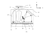
図1は、実施例1の測色装置としての分光測色器10の概略構成を説明するための断面図である。ここで、後述するラインセンサ11の長手方向をX軸方向、ラインセンサ11から後述する被測色物14に向かう方向をZ軸方向、X軸方向及びZ軸方向に直交する方向をY軸方向とする。図1では、被測色物(被測色材)14の被検知面(表面)に対して垂直方向の断面(XZ断面)を示している。本実施例の分光測色器10は、可視光全体にわたる発光波長分布を有する白色光源(以下、光源)12、照射側の集光・導光レンズ(以下、照射ライトガイド)19を有する。更に、本実施例の分光測色器10は、入射側の集光・導光レンズ(以下、入射ライトガイド)17、スリット22、回折格子(凹面反射回折格子)18、複数の画素を備える電荷蓄積型ラインセンサ(以下、ラインセンサ)11を有する。ここで、光源12は発光素子に相当する。また、回折格子18は分光手段に相当する。また、ラインセンサ11は受光素子に相当する。
[Color measuring device]
FIG. 1 is a cross-sectional view for explaining a schematic configuration of a
基板21は、紙にエポキシ樹脂を含浸したもの又はガラス繊維製の布を重ねエポキシ樹脂を含浸したものが好適に使用される。基板21上には、分光測色器10の動作を制御する制御演算部21cが設けられている。制御演算部21cは、光源12の発光量や発光タイミングを制御するための回路、及び、ラインセンサ11から出力された信号を処理するための演算回路を備えている。
As the
[測色装置内の各部材の位置決めと構成]
次に、照射ライトガイド19、入射ライトガイド17、スリット22、回折格子18、及び基板21のそれぞれの位置決め方法について説明する。図2(a)は分光測色器10をZ軸+方向から見た概略図、図2(b)は図2(a)のA−A断面図、図2(c)は図2(a)のB−B断面図、図2(d)は図2(a)のC−C断面図、図2(e)は図2(a)のD−D断面図である。分光測色器10は、ハウシングを構成する筐体10aと蓋10b(図3参照)を有する。ハウジングの筐体10aに照射ライトガイド19、入射ライトガイド17、スリット22、回折格子18、及び基板21がそれぞれ位置決め固定される。
[Positioning and configuration of each member in the color measuring device]
Next, positioning methods of the
図2(b)は、照射ライトガイド19と筐体10aとの関係を示しており、照射ライトガイド19は、Y軸+方向に筐体10aに突き当てられた状態で位置決めされ、紫外線硬化接着剤によって筐体10aに固定される。図2(c)の入射ライトガイド17、図2(d)のスリット22、図2(e)の回折格子18も同様に、Y軸+方向に筐体10aに突き当てられた状態で位置決めされ、紫外線硬化接着剤によって筐体10aに固定される。
FIG. 2B shows the relationship between the
次に、筐体10a、蓋10b、基板21の関係について詳しく説明する。図3は測色装置のハウジングの斜視図である。図3(a)は、分光測色器10のハウジングが組み立てられた状態を示す。図3(b)は、分光測色器10のハウジングが組み立てられる前の状態を示す図である。なお、内部に固定されている照射ライトガイド19、入射ライトガイド17、スリット22、回折格子18は不図示としている。これらの図からわかるように、筐体10aに対してZ軸方向に蓋10b及び基板21が取り付けられる。蓋10bは筐体10aに設けられた溝に嵌ることでその位置が決まり、紫外線硬化接着剤によって固定される。一方、基板21には、X軸方向及びY軸方向の位置決めの基準となる基準穴21aが設けられ、筐体10aに設けられた不図示のボスと嵌合することで、基板21のX軸方向及びY軸方向の位置決めがなされる。更に、基板21には切欠き部21bが設けられ、切欠き部21bが筐体10aに設けられた不図示の凸部に嵌合することで、基板21のZ軸回りの回転止めとなる。基板21は紫外線硬化接着剤によって筐体10bに固定される。
Next, the relationship between the
[測色原理]
分光測色器10の測色原理について説明する。図1に示す光源12から照射された光15は、照射側の照射ライトガイド19により集光され、被測色物14の被検知面に約45°の角度で入射するよう、方向を変えられる。ここで、被測色物14は、分光測色器10の予め設定された位置(図1では分光測色器10の上方に対向する位置)に位置した状態で測色される。被測色物14に約45°の角度で入射した光15は、被測色物14の光吸収特性に応じた散乱光(反射光)となる。散乱光16の一部は、入射側の入射ライトガイド17に取り込まれて平行光となった後、スリット22に入射するよう、方向を変えられる。そして、散乱光16はスリット22を通過し回折格子18に入射する。回折格子18に入射した散乱光16は、回折格子18で反射すると、回折格子18により分光され、且つ、波長毎に分光及び集光された分光光束となる。ラインセンサ11は、実質的に回折格子18のローランド円(不図示)の接線上に配置されており、回折格子18からの分光光束を波長毎に各画素で受光し検出する。
[Color measurement principle]
The color measurement principle of the
図3(c)は、本実施例のラインセンサ11を示す概略図である。図3(c)に示すように、本実施例では、波長が約350nm(ナノメートル)から約750nmの可視光を約3nm単位で検出するために必要な1方向に並んだ134画素で、ラインセンサ11を構成している。ラインセンサ11は、入射(受光)した分散光の強度に応じて、画素毎に電圧信号(電気信号)を出力する。そして、出力された電圧信号をAD変換器(不図示)によってアナログ信号からデジタル信号に変換(以下、AD変換)することにより、ラインセンサ11は、被測色物14からの反射光を画素毎のデジタル強度信号として得る。本実施例のラインセンサ11は電荷蓄積型ラインセンサであり、所定の蓄積時間に入射した分散光の強度に応じて、画素毎に電圧信号を出力する。ラインセンサ11の蓄積時間は、制御演算部21cによって適宜調整することが可能である。
FIG. 3C is a schematic diagram showing the
これら画素毎のデジタル強度信号は、ラインセンサ11から制御演算部21cに出力され、制御演算部21cは、380nmから730nmの範囲の、測色に関する値である分光反射率を10nm毎に算出して、分光測色器10の外部へ出力する。制御演算部21cによる分光反射率の算出方法については、後述する。また、本実施例では、記録材Pに含まれる蛍光白色剤の影響を小さくするために、光源12に発光波長が455nmで蛍光体を組み合わせた白色LEDを用いている。
The digital intensity signal for each pixel is output from the
[光源の発光スペクトル]
図4は、本実施例の分光測色器10に用いた光源12(本実施例では、白色LED)の発光スペクトルである。図4は、横軸に波長(nm)、縦軸に波長455nmでの発光強度を1としたときの各波長における発光強度を示している。図4に示すように、本実施例の光源12は、波長430nm以下での発光強度が弱く、更に波長420nm以下での発光強度は0となる。即ち、本実施例の光源12は、波長420nm以下では光量が得られない。このため、従来の方法では、波長430nm以下の分光反射率を算出する際には、精度が低下してしまう。本実施例では、波長430nmより大きい波長域における分光反射率から、波長430nm以下の分光反射率を予測(外挿、補外)することで、精度の向上を図る。本実施例の分光反射率の予測方法についても、後述する。
[Light emission spectrum of light source]
FIG. 4 is an emission spectrum of the light source 12 (white LED in this embodiment) used in the
[画像形成装置]
本実施例の分光測色器10は、例えば電子写真方式のカラー画像形成装置に適用することが可能である。その一例として、中間転写ベルトを採用したタンデム方式のカラー画像形成装置に分光測色器10を適用した場合について説明する。図5(a)は、本実施例の分光測色器10を適用した画像形成装置の概略構成を示す断面図である。まず、図5(a)を用いて本実施例の画像形成装置の画像形成部の動作について説明する。ここで、各画像形成部(画像形成手段)の構成及び動作は、用いるトナーの色(イエロー(Y)、マゼンタ(M)、シアン(C)、ブラック(K))が異なることを除いて実質的に同じである。従って、以下の説明において特に区別を要しない場合は、いずれかの色用に設けられた要素であることを表すために図5(a)中符号に与えた添え字Y、M、C、Kは省略して総括的に説明する。
[Image forming apparatus]
The
本実施例の画像形成部は、給送部44、各色のステーション毎の像担持体である感光ドラム31、帯電手段である帯電ローラ32、スキャナ部33、現像手段である現像器38を備える。また、画像形成部は、中間転写ベルト37、中間転写ベルト37を駆動する駆動ローラ41、張架ローラ40、補助ローラ42、一次転写ローラ34、二次転写ローラ43、定着部51を備える。更に、画像形成部は、画像形成部の画像形成動作を制御する制御部55及びコントローラ部56を備える。感光ドラム31は、アルミシリンダの外周に有機光導伝層が塗布されて構成され、図示しない駆動モータの駆動力が伝達されて回転するもので、駆動モータは感光ドラム31を画像形成動作に応じて図中矢印方向(時計回り方向)に回転させる。
The image forming unit of this embodiment includes a
制御部55が画像信号(入力信号)を受信すると、記録材Pは、給送部44(カセット等)から給送ローラ45、46によって画像形成装置内の搬送路に給送される。その後、記録材Pは、後述する画像形成動作と記録材Pの搬送動作との同期をとるためのレジストレーションローラ対(以下、単にレジストローラ対とする)47に一旦挟持され、停止して待機する。一方、コントローラ部56は、帯電ローラ32の作用により一定電位に帯電させた感光ドラム31の表面に、受信した画像信号に応じた静電潜像をスキャナ部33により形成させる。
When the
現像器38は、感光ドラム31上に形成された静電潜像を可視化する手段であり、ステーション毎にイエロー(Y)、マゼンタ(M)、シアン(C)、ブラック(K)のトナーを用いて、静電潜像の現像を行う。各現像器38には、スリーブ35が設けられており、スリーブ35には静電潜像を可視化するための現像電圧が印加されている。このように、各感光ドラム31の表面に形成された静電潜像は、各現像器38の作用により単色トナー像としてそれぞれ現像される。各々の感光ドラム31、帯電ローラ32、現像器38は一体構成となっており、画像形成装置本体から着脱可能なトナーカートリッジ39の形態で、画像形成装置本体に取り付けられている。 The developing device 38 is a means for visualizing the electrostatic latent image formed on the photosensitive drum 31, and uses yellow (Y), magenta (M), cyan (C), and black (K) toner for each station. The electrostatic latent image is developed. Each developing device 38 is provided with a sleeve 35 to which a developing voltage for visualizing the electrostatic latent image is applied. In this way, the electrostatic latent image formed on the surface of each photosensitive drum 31 is developed as a single color toner image by the action of each developing device 38. Each of the photosensitive drum 31, the charging roller 32, and the developing unit 38 is integrated, and is attached to the main body of the image forming apparatus in the form of a toner cartridge 39 that is detachable from the main body of the image forming apparatus.
中間転写ベルト37は、各感光ドラム31に接触しており、カラー画像形成時に図5(a)の矢印方向(反時計回り方向)に各感光ドラム31の回転と同期して回転する。感光ドラム31上で現像された単色トナー像は、一次転写ローラ34に印加された一次転写電圧の作用により順次、中間転写ベルト37に転写され(一次転写)、中間転写ベルト37上で重畳されて多色トナー像となる。その後、中間転写ベルト37上に形成された多色トナー像は、駆動ローラ41と二次転写ローラ43とで形成される二次転写部(ニップ部)に搬送される。一方、レジストローラ対47に挟持された状態で待機していた記録材Pは、レジストローラ対47の作用により中間転写ベルト37上の多色トナー像と同期を取りながら二次転写部に搬送される。そして、中間転写ベルト37上の多色トナー像が二次転写ローラ43に印加された二次転写電圧の作用により記録材Pに一括転写される(二次転写)。
The
定着部51は、記録材Pを搬送させながら、転写された多色トナー像を溶融定着させるもので、記録材Pを加熱する定着ローラ51aと、記録材Pを定着ローラ51aに圧接させるための加圧ローラ51bを備えている。定着ローラ51aと加圧ローラ51bは中空状に形成され、内部にそれぞれヒータ51ah、51bhが内蔵されている。多色トナー像を保持した記録材Pは、定着ローラ51aと加圧ローラ51bにより搬送されるとともに、熱及び圧力を加えられることで、トナーが記録材Pの表面に定着される。
The fixing unit 51 melts and fixes the transferred multi-color toner image while conveying the recording material P. The fixing unit 51 heats the recording material P and presses the recording material P against the fixing
トナー像が定着した後の記録材Pは、排出ローラ50によって排出トレイ52に排出されて画像形成動作が終了されるか、又は記録材Pの2面目への画像形成が行われる場合には排出ローラ50によりスイッチバックされる(折り返して搬送される)。記録材Pの2面目への画像形成動作が行われる場合、1面目(片面)に多色トナー像を保持した記録材Pは、排出ローラ50によるスイッチバック動作によって両面搬送路Dを経由して、再びレジストローラ対47に一旦挟持されて停止して待機する。その後、上述した一連の画像形成動作が行われて記録材Pの2面目への画像形成が行われる。クリーニング手段であるクリーニング装置48は、記録材Pに転写されず中間転写ベルト37上に残留したトナー(転写残トナー)をクリーニングするもので、クリーニング装置48により回収されたトナーはクリーナ容器49に蓄えられる。
The recording material P after the toner image has been fixed is discharged to the
本実施例の分光測色器10は、被測色物14としての記録材Pに形成された後述する測色用パッチ画像Tを構成するトナーパッチ(測色用パッチ)を測色する目的で、両面搬送路D中の長手方向の中央位置に配置されている。ここで、長手方向とは、両面搬送路Dを搬送される記録材Pの画像形成面における搬送方向に直交する方向(感光ドラム31の回転軸方向)をいう。また、画像形成装置の長手方向は、図1等のX軸方向に相当する。本実施例の画像形成装置では、画像形成装置内に設けられた制御部55が、分光測色器10による測色結果に基づいて、各画像形成部の画像形成条件を調整している。画像形成条件の調整とは、画像データの補正や、露光光量、現像電圧、転写電圧等の調整である。
The
[トナーパッチの測色動作]
以下に、分光測色器10によるトナーパッチの測色動作について説明する。図5(b)は、記録材Pに形成された測色用パッチ画像Tを示す概略図である。分光測色器10によるトナーパッチの測色動作が開始されると、前述した一連の画像形成動作により記録材Pに図5(b)に示すような測色用パッチ画像Tが形成される。定着部51を通過し、定着後の測色用パッチ画像Tを担持した記録材Pは、排出ローラ50によるスイッチバック動作によって両面搬送路Dへと引き込まれる。そして、両面搬送路D中に配置された分光測色器10によって、記録材Pに形成された測色用パッチ画像Tが、記録材Pの搬送と同期しながら順次測色される。その後、レジストローラ対47を通過した記録材Pは、二次転写部、定着部51を通過して排出ローラ50によって排出トレイ52に排出される。このような一連の画像形成動作は、画像形成装置内に設けられた制御部55によって制御される。
[Toner patch color measurement]
Hereinafter, the color measurement operation of the toner patch by the
[画像形成装置のブロック図]
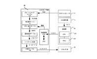
次に、本実施例の画像形成装置における画像処理動作の一例を、図6に示すブロック図を用いて説明する。画像形成装置のコントローラ部56と制御部55は、ビデオインターフェースで接続され、コントローラ部56が外部端末のホストコンピュータ57や不図示のネットワークに接続される。コントローラ部56の記憶部には、色変換に用いるカラーマッチングテーブル(CM)、色分解テーブル(C1)、カラー補正テーブル(C2)が記憶されている。また、制御部55には、画像形成処理や分光測色器10からの測色結果の処理を実行するCPU202と、分光測色器10による測色結果を一時的に記憶するメモリ203が搭載されている。
[Block diagram of image forming apparatus]
Next, an example of an image processing operation in the image forming apparatus according to the present exemplary embodiment will be described with reference to a block diagram illustrated in FIG. The
画像形成動作が開始されると、次のような処理が行われる。コントローラ部56は、予め用意されているカラーマッチングテーブル(CM)により、ホストコンピュータ等から送られてくる画像の色を表すRGB信号をカラー画像形成装置の色再現域に合わせたデバイスRGB信号(以下、DevRGB)に変換する。続いてコントローラ部56は、色分解テーブル(C1)及び後述するカラー補正テーブル(C2)により、DevRGB信号をカラー画像形成装置のトナー色材色であるCMYK信号に変換する。そして、コントローラ部56は、各々のカラー画像形成装置に固有の階調−濃度特性を補正する濃度補正テーブル(D)により、CMYK信号を階調−濃度特性の補正を加えたC’M’Y’K’信号へ変換する。その後コントローラ部56は、ハーフトーン処理を行い、C’M’Y’K’信号をC’’M’’Y’’K’’信号へ変換する。そしてコントローラ部56は、PWMテーブル(PW)により、C’’M’’Y’’K’’信号に対応するスキャナ部33C、33M、33Y、33Kの露光時間Tc、Tm、Ty、Tkへ変換する。ここで、PWMは、パルス幅変調(Pulse Width Modulation)である。コントローラ部56は、露光時間Tc、Tm、Ty、Tkに従ってスキャナ部33を制御することで、感光ドラム31C、31M、31Y、31Kの表面に静電潜像を形成し、上述した一連の画像形成動作を行う。
When the image forming operation is started, the following processing is performed. The
また、分光測色器10によるトナーパッチ画像の測色動作においては、予めカラーパッチデータとしてコントローラ部56に格納されている複数個のCMYK形式のカラーパッチデータ(CPD)に従って、記録材Pに測色用パッチ画像Tが形成される。記録材P上(被測色物14上)(記録材上)に形成された測色用パッチ画像Tは、分光測色器10で測色され、それぞれのパッチ毎に分光反射率Or(λ)が算出され、制御演算部21cから制御部55へ出力される。分光測色器10により算出された分光反射率Or(λ)のデータは、制御部55によって色度値(例えば、CIE L*a*b*)に変換されてコントローラ部56の色変換部へ送られる。そして、色変換部では、不図示のCMS(カラーマネージメントシステム)を利用して、色度値が画像形成装置に依存するCMYK形式のデータ(CSD)に変換される。その後、色変換部では、変換されたCMYKデータ(CSD)と、デフォルトのカラーパッチデータ(CPD)とを比較することによって、その差を補正するようなカラー補正テーブル(C2)が生成される。
Further, in the colorimetric operation of the toner patch image by the
これらの処理は、測色された全ての測色用パッチに対して行われるが、測色されるパッチは画像形成装置で再現可能な全ての色を必ずしも揃えている必要はない。例えば、複数色からなる混色グレーのパッチを作成してグレー軸補正のみを行ってもよい。又は、C、M、Y、Kのうち、測色を行いたい色のパッチを単色で作成して測色を行ってもよい。測色用パッチとして記録材Pに形成されていないCMYKデータに関しては、測色されたパッチを基に補間処理を行うことでカラー補正テーブル(C2)を作成すればよい。このようにして作成されたカラー補正テーブル(C2)は、コントローラ部56により更新、保持される。
These processes are performed on all colorimetric patches that have been colorimetrically measured, but the colorimetric patches need not necessarily have all colors that can be reproduced by the image forming apparatus. For example, a mixed color gray patch composed of a plurality of colors may be created to perform only the gray axis correction. Alternatively, color measurement may be performed by creating a single color patch of C, M, Y, and K to be measured. For CMYK data that is not formed on the recording material P as a colorimetric patch, a color correction table (C2) may be created by performing interpolation processing based on the colorimetric patch. The color correction table (C2) created in this way is updated and held by the
[分光反射率の算出方法]
次に、本実施例の分光反射率の算出方法について説明する。本実施例においては、光源12の発光光量が得られない380nmから420nmの分光反射率を、光源12の発光光量が得られ、精度良く分光反射率を算出することが可能な440nmと450nmの分光反射率を用いて予測(外挿)する。上述したように、被測色物14を測色する場合、散乱光16はスリット22を通過し回折格子18で分光され、かつ、波長毎に分光及び集光された分光光束となり、ラインセンサ11の各画素で受光され検出される。ここで、ラインセンサ11のアドレス番号n(n=1〜134)(図3(c)参照)と、画素毎の電圧信号の出力をOi(n)とする。
[Calculation method of spectral reflectance]
Next, a method for calculating the spectral reflectance according to the present embodiment will be described. In this embodiment, a spectral reflectance of 380 nm to 420 nm at which the light emission amount of the
ラインセンサ11の各画素は、アドレス番号n(n=1〜134)と波長λとが予め対応付けられ、制御演算部21cのメモリ部(不図示)に保持されている。以下、アドレス番号nと波長λとが対応付けられることを、値付けという。この値付けの作業は、例えばラインセンサ11の出荷時に波長が既知の基準単一波長スペクトルを用いるなどして、公知の方法にて行うことができる。
Each pixel of the
このように、ラインセンサ11の各画素のアドレス番号nと波長λが対応付けられることで、画素毎の電圧信号が出力されることによって、被測色物14からの反射光の波長に対応した信号強度スペクトルOi(λ)が得られる。即ち、ラインセンサ11の画素毎の信号強度スペクトルOi(n)から、波長毎の信号強度スペクトルOi(λ)に変換することが可能となる。本実施例では、この変換の際に、分光反射率を10nm毎になるよう補間演算を行う。分光反射率が10nm毎になるよう補間を行うのは、制御演算部21cのメモリ部(不図示)の容量や、演算の負荷を考慮し、また、色度値(例えば、CIE L*a*b*)を算出する場合の精度として十分である理由からである。なお、分光反射率を5nm毎になるよう補間を行ってもよい。
As described above, the address number n of each pixel of the
被測色物14の分光反射率Or(λ)は、次の式(1)により求められる。
Or(λ)={Oi(λ)/Wi(λ)}×Wr(λ)・・・式(1)
ここで、430nm≦λ≦730nm
ここで、Wi(λ)は、別途測定される分光反射率が既知の基準部材である基準試料(一般には白色基準試料)に光源12の光を照射したときの反射光の波長に対応した信号強度スペクトルである。また、Wr(λ)は、基準試料自身が有する分光反射率である。なお本実施例では、光源12の発光光量が得られる430nmから730nmの分光反射率については、式(1)を用いて算出する。
The spectral reflectance Or (λ) of the measured
Or (λ) = {Oi (λ) / Wi (λ)} × Wr (λ) (1)
Here, 430 nm ≦ λ ≦ 730 nm
Here, Wi (λ) is a signal corresponding to the wavelength of the reflected light when the light of the
一方、図4で説明したように、光源12の発光光量が得られない380nmから420nmの分光反射率は、光源12の発光光量が得られる440nmと450nmの分光反射率から、波長と分光反射率の関係を示す直線を求めて外挿して算出する。具体的な方法は、次の式(2)、式(3)のとおりである。
α=(Or(450)−Or(440))/10・・・式(2)
Or(λ)=α×(λ−440)+Or(440)・・・式(3)
ここで、380nm≦λ≦420nm
以上より、可視光領域である380nmから730nmの全範囲において、分光反射率を10nm毎に算出することが可能となる。
On the other hand, as described with reference to FIG. 4, the spectral reflectance of 380 nm to 420 nm in which the light emission amount of the
α = (Or (450) −Or (440)) / 10 Equation (2)
Or (λ) = α × (λ−440) + Or (440) (3)
Here, 380 nm ≦ λ ≦ 420 nm
As described above, the spectral reflectance can be calculated every 10 nm in the entire visible light region from 380 nm to 730 nm.
[比較例]
次に、本実施例の効果を明確にするための比較例について説明する。比較例としては、光源12の発光光量が得られない380nmから420nmの分光反射率においても、式(1)を用いて分光反射率を算出した。
[Comparative example]
Next, a comparative example for clarifying the effect of the present embodiment will be described. As a comparative example, the spectral reflectance was calculated using the formula (1) even in the spectral reflectance from 380 nm to 420 nm where the light emission amount of the
本実施例の効果確認として、記録材Pに測色用パッチ画像Tを形成し、形成した測色用パッチ画像Tを分光測色器10により測色し、本実施例と比較例で評価した。表1は、評価で用いた測色用パッチ画像Tを構成するパッチと測色時の繰り返し再現性の結果である。測色用パッチ画像Tは、表1に示すように、イエロー(Y)、マゼンタ(M)、シアン(C)の画像データを変えた計15色を用いており、それぞれパッチ番号(パッチNo)1〜15としている。例えば、パッチNo1のパッチは、イエローが0、マゼンタが0、シアンが100であり、シアン色のパッチである。また、パッチNo4のパッチは、イエローが0、マゼンタが100、シアンが100であり、青色のパッチである。 As a confirmation of the effect of this example, a colorimetric patch image T was formed on the recording material P, and the colorimetric patch image T thus formed was measured by the spectrocolorimeter 10 and evaluated in this example and the comparative example. . Table 1 shows the results of the reproducibility at the time of color measurement and the patches constituting the color measurement patch image T used in the evaluation. As shown in Table 1, the colorimetric patch image T uses a total of 15 colors obtained by changing the image data of yellow (Y), magenta (M), and cyan (C), and each has a patch number (patch number). 1-15. For example, the patch No. 1 is a yellow patch with yellow being 0, magenta being 0, and cyan being 100. The patch No. 4 is a blue patch with yellow being 0, magenta being 100, and cyan being 100.
これら15色のパッチからなる測色用パッチ画像Tを、分光測色器10により測色した。また、測色時の繰り返し再現性は、以下のように評価した。まず、15色の各パッチを分光測色器10により100回測定し、制御演算部21cにより本実施例と比較例でそれぞれ分光反射率を算出した。その後、制御演算部21cにより算出した分光反射率を用いて制御部55により色度CIE L*a*b*(D50)を求めた。そして、制御部55により15色のパッチ毎にL*a*b*の平均値を算出し、算出した平均値と各測定時に求めたL*a*b*との差(以下、色差)ΔE(CIE 1994)を算出した。そして、100回測定して得られた色差ΔEの標準偏差を算出し、算出した色差ΔEの標準偏差を15色の各パッチの測色時の繰り返し再現性とした。
The colorimetric patch image T composed of these 15 color patches was measured by the
また、表1の下段にあるAveは、参考値として15色のパッチ毎に得られた色差ΔEの標準偏差を平均化した値であり、Maxは、色差ΔEの標準偏差の最大値である。

表1には、左の列から、測色用パッチ画像Tを構成するパッチの番号(パッチNo)、イエロー、マゼンタ、シアンの画像データ、本実施例の測色時の色差ΔEの標準偏差、比較例の測色時の色差ΔEの標準偏差、をそれぞれ示す。表1に示すように、15色の全てのパッチにおいて、本実施例の方が、比較例に比べて色差ΔEの標準偏差が小さくなっていることがわかる。例えば、パッチNo1では、比較例では0.19であるのに対し、本実施例では0.13となっており、色差ΔEの標準偏差が小さくなっている。即ち、本実施例の分光反射率の外挿方法によって、測色時の繰り返し再現性が従来に比較して改善されていることが確認できる。 Table 1 shows, from the left column, the number of patches constituting the colorimetric patch image T (patch No.), yellow, magenta, and cyan image data, the standard deviation of the color difference ΔE during colorimetry according to this embodiment, The standard deviation of the color difference ΔE during colorimetry in the comparative example is shown respectively. As shown in Table 1, it can be seen that the standard deviation of the color difference ΔE is smaller in this example than in the comparative example in all the patches of 15 colors. For example, in patch No. 1, it is 0.19 in the comparative example, but is 0.13 in this embodiment, and the standard deviation of the color difference ΔE is small. That is, it can be confirmed that the reproducibility at the time of color measurement is improved as compared with the prior art by the extrapolation method of the spectral reflectance of this embodiment.
以上説明したように、本実施例によれば、光源12の発光光量が得られない380nmから420nmの分光反射率を、光源12の発光光量が得られる440nmと450nmの分光反射率を用いて予測する構成とする。これにより、分光測色器10による測色精度を向上させることができる。なお、本実施例では、可視光領域の短波長側の分光反射率の予測について述べたが、例えば可視光領域の長波長側で光量が得られない白色LEDを分光測色器10の光源12に用いた場合でも、同様の予測を行うことで、測色精度を向上させることができる。
As described above, according to the present embodiment, the spectral reflectance of 380 nm to 420 nm where the light emission amount of the
分光測色器の照明光として白色LEDを用いる際は、発光波長が400nm付近の近紫外LEDに、蛍光体を組み合わせた白色LEDが一般的に使用されている。また、カラープリンタの色味の安定化を制御するためには、記録紙上に試験的な画像を形成して測色を行うが、一般的な記録紙は、白色度を上げるための蛍光白色剤を含有している。蛍光白色剤は、近紫外領域の光エネルギーを吸収し、430nm波長付近の光エネルギーを放出している。このため、白色LEDの近紫外領域の光量と、記録紙に含まれる蛍光白色剤の割合などで、430nm付近の蛍光される光量が変動してしまい、その結果、測色精度を低下させる要因となっている。特に白色LEDにおいては、D50、D65(CIEの標準光源)といった自然光より近紫外領域の発光スペクトルが強い。このため、白色LEDにおいては、記録紙に含有されている蛍光白色剤の影響を受け易く、測色精度が低下するおそれがある。この対策として、UVカットフィルターを用いて紫外光をカットし測色精度を向上させる方法があるが、この場合、分光測色器や分光測色器を備える画像形成装置のコストアップとなるおそれがある。 When a white LED is used as illumination light for a spectrocolorimeter, a white LED in which a phosphor is combined with a near-ultraviolet LED having an emission wavelength near 400 nm is generally used. In addition, in order to control the stabilization of the color of a color printer, a test image is formed on a recording paper and colorimetry is performed. A general recording paper is a fluorescent whitening agent for increasing whiteness. Contains. The fluorescent white agent absorbs light energy in the near ultraviolet region and emits light energy in the vicinity of a wavelength of 430 nm. For this reason, the amount of light emitted in the vicinity of 430 nm varies depending on the amount of light in the near ultraviolet region of the white LED and the ratio of the fluorescent whitening agent contained in the recording paper. As a result, the color measurement accuracy is reduced. It has become. In particular, in the white LED, the emission spectrum in the near ultraviolet region is stronger than natural light such as D50 and D65 (CIE standard light source). For this reason, in white LED, it is easy to receive to the influence of the fluorescent white agent contained in the recording paper, and there exists a possibility that colorimetric accuracy may fall. As a countermeasure, there is a method of improving the colorimetric accuracy by cutting ultraviolet light using a UV cut filter. In this case, there is a risk that the cost of an image forming apparatus equipped with a spectrocolorimeter or a spectrocolorimeter is increased. is there.
一方、発光波長が440nm付近の青色LEDと蛍光体を組み合わせた白色LEDを用いると、紫外光を含まないため、UVカットフィルターを用いる必要がなく、記録紙に含まれる蛍光白色剤の影響を少なくすることが可能となる。更に、発光波長が青色となるので、材料費、流通量などにより安価な白色LEDを用いることが可能となる。しかし、発光波長が440nm付近の青色LEDと蛍光体を組み合わせた白色LEDを用いた場合では、420nm以下の光量がほとんど得られない。本実施例では、このような安価な白色LEDを用いた場合でも、420nm以下の光量を予測することが可能となる。 On the other hand, when a white LED that combines a blue LED having a light emission wavelength of around 440 nm and a phosphor is used, it does not contain ultraviolet light, so there is no need to use a UV cut filter, and the influence of the fluorescent whitening agent contained in the recording paper is reduced. It becomes possible to do. Furthermore, since the emission wavelength is blue, an inexpensive white LED can be used due to material costs, distribution amount, and the like. However, when a white LED that combines a blue LED having an emission wavelength of around 440 nm and a phosphor is used, an amount of light of 420 nm or less is hardly obtained. In this embodiment, even when such an inexpensive white LED is used, a light amount of 420 nm or less can be predicted.
なお、本実施例では、光量が得られない光源の一例として波長420nm以下での発光強度は0となるものを説明したが、光源はこれに限られるものではない。例えば、発光強度は0でなくとも、所定の発光強度以下となってしまう波長に関しても、測色精度が低下してしまうことがある。このような、ある波長における発光強度が所定の発光強度より低くなってしまう光源を分光測色器10に用いた場合においても、上述した方法と同様の予測を行うことで、測色精度を向上させることができる。
In this embodiment, an example in which the light emission intensity at a wavelength of 420 nm or less is 0 is described as an example of a light source from which a light amount cannot be obtained, but the light source is not limited to this. For example, even if the light emission intensity is not 0, the colorimetric accuracy may be lowered even with respect to a wavelength that is below a predetermined light emission intensity. Even when such a light source whose emission intensity at a certain wavelength is lower than a predetermined emission intensity is used in the
なお、本実施例では、画像形成装置の制御部55と分光測色器10の制御演算部21cで各々制御する方法を説明したが、これに限られるものではない。例えば、画像形成装置の制御部55が制御手段として、分光測色器10の動作を制御することもできる。画像形成装置の制御部55により、一つのCPUを用いて制御するような場合であれば、分光測色器10は制御演算部を有さないような構成であってもよい。
In the present embodiment, the method of controlling by the
また、本実施例の予測方法は分光測色器10内で独立して行うことが可能である。ここでは一例として、画像形成装置100内に分光測色器10を配置する構成を示したが、分光測色装置として分光測色器10が独立して測色を行うような場合においても、上述した予測方法を行うことが可能である。
In addition, the prediction method of this embodiment can be performed independently in the
以上本実施例によれば、測色装置における測色精度の向上を図ることができる。 As described above, according to this embodiment, it is possible to improve the color measurement accuracy in the color measurement device.
次に、実施例2について説明する。なお、実施例1と同様の構成部分については同一の符号を付して、その説明は省略する。本実施例では、光源12の発光光量が得られない380nmから420nmの分光反射率を、光源12の発光光量が得られる430nm以上で、かつ、トナーの分光反射率で特徴的な箇所の波長での分光反射率を用いて予測する。ここで、トナーの分光反射率で特徴的な箇所の波長とは、例えば次の(1)〜(4)のいずれかの波長域をいう。即ち、(1)トナーの分光反射率で光を吸収する(分光反射率が0付近)波長域、(2)光の反射率が最大の波長域、(3)他の波長域と比較して反射率が高い波長域、又は、(4)他の波長域と比較し反射率が低い波長域である。本実施例では、これら(1)〜(4)のいずれかの波長域で求めた分光反射率を用いて、光源12の発光光量が得られない波長域での分光反射率を求める。
Next, Example 2 will be described. In addition, the same code | symbol is attached | subjected about the component similar to Example 1, and the description is abbreviate | omitted. In this embodiment, the spectral reflectance of 380 nm to 420 nm at which the light emission amount of the
[各色トナーの分光反射率]
図7は、各色トナーの分光反射率を示す図であり、横軸に波長(nm)、縦軸に各波長における分光反射率を示す。図7に示すように、分光反射率は、トナーの色、即ち色材によって異なる分布を示す。図7にピッチの狭い破線で示すイエローは、440nm付近で分光反射率が最も低くなっている。即ち、イエローでは、440nm付近が上述した(4)に該当する。図7にピッチの広い破線で示すマゼンタは、540nm付近で分光反射率が最も低くなっている。即ち、マゼンタでは、540nm付近が上述した(4)に該当する。図7に実線で示すシアンは、470nm付近で分光反射率が最も高くなっている。即ち、シアンでは、470nm付近が上述した(2)又は(3)に該当する。
[Spectral reflectance of each color toner]
FIG. 7 is a diagram showing the spectral reflectance of each color toner, where the horizontal axis indicates the wavelength (nm) and the vertical axis indicates the spectral reflectance at each wavelength. As shown in FIG. 7, the spectral reflectance shows a distribution that varies depending on the color of the toner, that is, the color material. In FIG. 7, yellow indicated by a broken dotted line has the lowest spectral reflectance around 440 nm. That is, in yellow, the vicinity of 440 nm corresponds to the above (4). In FIG. 7, magenta indicated by a broken line having a wide pitch has the lowest spectral reflectance around 540 nm. That is, in magenta, the vicinity of 540 nm corresponds to the above (4). Cyan indicated by a solid line in FIG. 7 has the highest spectral reflectance around 470 nm. That is, in cyan, the vicinity of 470 nm corresponds to (2) or (3) described above.
また、680nm付近では、イエロー、マゼンタでは分光反射率が高く、シアンは分光反射率が低くなっている。即ち、イエロー、マゼンタでは、680nm付近が上述した(2)又は(3)に該当する。また、シアンでは、680nm付近が上述した(4)に該当する。更に、イエローは440nm付近、マゼンタ540nm付近、シアン680nm付近が、それぞれ(1)にも該当する。以上のことから、本実施例では、光源12の発光光量が得られる波長域の中で上述した(1)〜(4)の条件を満たす440nm、470nm、540nm、680nmでの分光反射率を用いることとする。そして、この4つの波長における分光反射率を用いて、光源12の発光光量が得られない380nmから420nmの分光反射率を予測(外挿)する。
In the vicinity of 680 nm, yellow and magenta have high spectral reflectance, and cyan has low spectral reflectance. That is, in yellow and magenta, the vicinity of 680 nm corresponds to the above (2) or (3). In cyan, the vicinity of 680 nm corresponds to (4) described above. Further, yellow corresponds to (1) near 440 nm, magenta 540 nm, and
[分光反射率の算出方法]
本実施例の分光反射率の算出方法について説明する。光源12の発光光量が得られる430nmから730nmまでの分光反射率については、実施例1と同様の方法で分光反射率を算出する。即ち、画像形成装置の制御部55は、記録材P上に図5(b)で説明した測色用パッチ画像Tを形成する。そして、分光測色器10により測色用パッチ画像Tを測色する。分光測色器10の制御演算部21cは430nmから730nmまでの分光反射率を、上述した式(1)を用いて求める。一方、本実施例では、分光測色器10の制御演算部21cは、380nmから420nmの分光反射率を、次の式(4)、式(5)を用いて測色用パッチ画像Tの各パッチについての分光反射率Or(λ)を求め、制御部55に出力する。
β=A×Or(440)+B×Or(470)+C×Or(540)
+D×Or(680)+E・・・式(4)
Or(λ)=β×(λ−440)+Or(440)・・・式(5)
ここで、380nm≦λ≦420nm
ここで、A、B、C、D、Eは係数で、予めメモリ(不図示)に記憶されている値で、制御演算部21cで380nmから420nmまでの分光反射率を算出する際に使用される。本実施例では、係数Aは0.0146、係数Bは0.0002、係数Cは−0.0012、係数Dは−0.0006、係数Eは−0.0001としている。
[Calculation method of spectral reflectance]
A method of calculating the spectral reflectance according to this embodiment will be described. For the spectral reflectance from 430 nm to 730 nm from which the amount of light emitted from the
β = A × Or (440) + B × Or (470) + C × Or (540)
+ D × Or (680) + E (4)
Or (λ) = β × (λ−440) + Or (440) (5)
Here, 380 nm ≦ λ ≦ 420 nm
Here, A, B, C, D, and E are coefficients, which are values stored in advance in a memory (not shown), and are used when the spectral reflectance from 380 nm to 420 nm is calculated by the
(係数A、B、C、D、Eの算出方法)
次に、係数A、B、C、D、Eの算出方法について説明する。まず、カラー画像形成装置で色空間が均一となるような300色のパッチを画像形成し、300色についての分光反射率を測定する。即ち、図7のようなグラフを300色分作成する。ここで、300色のパッチを測定する際に使用する測色器としては、本実施例で使用する分光測色器10を用いずに、可視光領域で光量を得ることができ、可視光領域の短波長側においても分光反射率を精度良く測定することができる測色器を用いる。また、使用される光源としては、記録紙Pの蛍光白色剤の影響を抑えるため、白色LEDを用いずに、例えばタングステンランプを用いた方が好ましい。更には、UVカットを行った方が好ましい。後述する比較例との比較実験においては、本実施例では、300色のパッチを測色する測色器として、Xrite社製のi1を使用し、UVカットフィルターを用いて測定した。
(Calculation method of coefficients A, B, C, D, E)
Next, a method for calculating the coefficients A, B, C, D, and E will be described. First, an image is formed with 300 color patches so that the color space is uniform in the color image forming apparatus, and the spectral reflectance for 300 colors is measured. That is, a graph as shown in FIG. 7 is created for 300 colors. Here, as a colorimeter used when measuring a 300-color patch, a light amount can be obtained in the visible light region without using the
このように、分光測色器10とは異なる測色器を用いて300色の分光反射率を測定した後、300色のパッチ毎に380nmから420nmの分光反射率を直線近似して、近似した直線の傾きを求める。ここで、直線の傾きは、300色のパッチを測定した実測値から求められる。次に、440nm、470nm、540nm、680nmでの分光反射率と、直線近似した380nmから420nmにおける傾きについて、300色のパッチ分の相関を回帰分析により求め、式(4)の係数A、B、C、D、Eを決定する。
As described above, after measuring the spectral reflectance of 300 colors using a colorimeter different from the
[比較例]
次に、本実施例の効果確認を行うため、実施例1と同様の評価を行った。比較例としては、光源12の発光光量が得られない380nmから420nmの分光反射率においても、実施例1で説明した式(1)を用いて分光反射率を算出した。
[Comparative example]
Next, in order to confirm the effect of this example, the same evaluation as in Example 1 was performed. As a comparative example, the spectral reflectance was calculated using the formula (1) described in Example 1 even in a spectral reflectance of 380 nm to 420 nm where the light emission amount of the
また、表1の実施例1の結果と比較しても、本実施例では、測色時の繰り返し再現性が向上している。例えば、全パッチの標準偏差の平均値(Ave)を比較すると、表1では0.17となっているのに対して、本実施例の表2では0.14となっている。このように、測色時の繰り返し再現性を向上するうえで、本実施例の予測の方が、より好ましいことがわかる。 In addition, compared with the results of Example 1 in Table 1, in this example, the reproducibility at the time of color measurement is improved. For example, when the average value (Ave) of the standard deviations of all patches is compared, it is 0.17 in Table 1 and 0.14 in Table 2 of this embodiment. Thus, it can be seen that the prediction of the present embodiment is more preferable in improving the reproducibility during colorimetry.
以上説明したように、本実施例によれば、光源12の発光光量が得られない380nmから420nmの分光反射率を、次のように予測する構成とする。即ち、光源12の発光光量が得られる430nm以上で、かつ、トナーの分光反射率で特徴的な箇所の波長での分光反射率を用いて予測することで、精度を向上させることができる。
As described above, according to the present embodiment, the spectral reflectance from 380 nm to 420 nm at which the light emission amount of the
以上本実施例によれば、測色装置における測色精度の向上を図ることができる。 As described above, according to this embodiment, it is possible to improve the color measurement accuracy in the color measurement device.
10 分光測色器
11 ラインセンサ
12 光源
14 被測色物
21c 制御演算部
DESCRIPTION OF
Claims (21)
前記被測色物に前記発光手段により光が照射されて反射された光を分光する分光手段と、
前記分光手段により分光された光を複数の素子により受光する受光手段と、
前記被測色物から反射された光を前記受光手段により受光した結果に基づき測色を行う制御手段と、
を備える測色装置であって、
前記発光手段は、第一の波長域は所定の光量よりも多い光量であり、第二の波長域は前記所定の光量よりも少ない光量である光を照射し、
前記制御手段は、前記発光手段から光を照射させ、前記第二の波長域で前記被測色物から反射された光を前記受光手段により受光した結果を用いることなく、前記第一の波長域で前記被測色物から反射された光を前記受光手段により受光した結果に基づいて、前記第二の波長域の測色に関する値を予測することを特徴とする測色装置。 A light emitting means for irradiating the color to be measured with light;
A spectroscopic means for spectroscopically analyzing the light reflected by the light emission means by the light emitting means;
A light receiving means for receiving light split by the spectroscopic means by a plurality of elements;
Control means for performing color measurement based on a result of receiving light reflected from the color object to be measured by the light receiving means;
A color measuring device comprising:
The light emitting means, the first wavelength region is greater amount than the predetermined amount, the second wavelength region is irradiated with light which is light weight yet less than the predetermined amount,
The control means irradiates light from the light emitting means, and uses the result of receiving light reflected from the color object to be measured in the second wavelength range by the light receiving means without using the first wavelength range. A colorimetric device that predicts a value related to colorimetry in the second wavelength range based on a result of receiving light reflected from the colorimetric object by the light receiving unit.
前記画像は、単色で形成される、又は複数色を混色して形成されることを特徴とする請求項1又は2に記載の測色装置。 The measured color object is an image formed on a recording material,
The color measurement device according to claim 1, wherein the image is formed with a single color or a mixture of a plurality of colors.
前記制御手段は、前記第一の波長域で前記被測色物から反射された光を前記受光手段により受光した結果と、前記基準部材から反射された光を受光した結果と、に基づいて、前記第一の波長域の分光反射率を求めることを特徴とする請求項4に記載の測色装置。 A reference member serving as a reference when performing color measurement of the color object to be measured;
The control means is based on the result of receiving the light reflected from the measured object in the first wavelength range by the light receiving means and the result of receiving the light reflected from the reference member, The colorimetric apparatus according to claim 4, wherein a spectral reflectance in the first wavelength region is obtained.
請求項1乃至10のいずれか1項に記載の測色装置と、
を備え、
前記画像形成手段により記録材上に形成された画像を前記測色装置により測色し、前記測色装置による測色の結果に基づいて、画像形成条件を調整する制御部を備えることを特徴とする画像形成装置。 Image forming means for forming an image on a recording material;
A colorimetric device according to any one of claims 1 to 10,
Equipped with a,
A control unit that measures an image formed on the recording material by the image forming unit using the color measurement device and adjusts image formation conditions based on a result of the color measurement by the color measurement device ; Image forming apparatus.
前記発光手段は、第一の波長域は所定の光量よりも多い光量であり、第二の波長域は前記所定の光量よりも少ない光量である光を照射し、
前記発光手段から光を照射させ、前記第二の波長域で前記被測色物から反射された光を前記受光手段により受光した結果を用いることなく、前記第一の波長域で前記被測色物から反射された光を前記受光手段により受光した結果に基づいて、前記第二の波長域の測色に関する値を予測する測色工程を備えることを特徴とする測色方法。 Light emitting means for irradiating light to the color object to be measured, Spectroscopic means for dispersing light reflected by the light emitting means on the color object to be measured, and a plurality of lights dispersed by the spectroscopic means A colorimetric method for a colorimetric device comprising: a light receiving means for receiving light by an element; and performing color measurement based on a result of receiving light reflected from the color measurement object by the light receiving means,
The light emitting means, the first wavelength region is greater amount than the predetermined amount, the second wavelength region is irradiated with light which is light weight yet less than the predetermined amount,
Irradiating light from the light emitting means, and using the result of receiving the light reflected from the color object to be measured in the second wavelength range by the light receiving means, the color to be measured in the first wavelength range. A colorimetry method comprising: a colorimetry step for predicting a value relating to colorimetry in the second wavelength region based on a result of receiving light reflected from an object by the light receiving unit.
前記画像は、単色で形成される、又は複数色を混色して形成されることを特徴とする請求項12又は13に記載の測色方法。 The measured color object is an image formed on a recording material,
The color measurement method according to claim 12 or 13 , wherein the image is formed by a single color or a mixture of a plurality of colors.
前記測色工程では、前記第一の波長域で前記被測色物から反射された光を前記受光手段により受光した結果と、前記基準部材から反射された光を受光した結果と、に基づいて、前記第一の波長域の分光反射率を求めることを特徴とする請求項15に記載の測色方法。 The color measurement device includes a reference member that serves as a reference when performing color measurement of the color object to be measured.
In the color measurement step, based on a result of receiving light reflected from the color object to be measured in the first wavelength range by the light receiving unit and a result of receiving light reflected from the reference member. The colorimetric method according to claim 15 , wherein a spectral reflectance in the first wavelength region is obtained.
Priority Applications (2)
| Application Number | Priority Date | Filing Date | Title |
|---|---|---|---|
| JP2014163743A JP6468752B2 (en) | 2014-08-11 | 2014-08-11 | Color measuring device, image forming apparatus, and color measuring method |
| US14/820,548 US10041834B2 (en) | 2014-08-11 | 2015-08-06 | Color measuring apparatus, image forming apparatus and color measuring method |
Applications Claiming Priority (1)
| Application Number | Priority Date | Filing Date | Title |
|---|---|---|---|
| JP2014163743A JP6468752B2 (en) | 2014-08-11 | 2014-08-11 | Color measuring device, image forming apparatus, and color measuring method |
Publications (3)
| Publication Number | Publication Date |
|---|---|
| JP2016038358A JP2016038358A (en) | 2016-03-22 |
| JP2016038358A5 JP2016038358A5 (en) | 2017-09-14 |
| JP6468752B2 true JP6468752B2 (en) | 2019-02-13 |
Family
ID=55267201
Family Applications (1)
| Application Number | Title | Priority Date | Filing Date |
|---|---|---|---|
| JP2014163743A Active JP6468752B2 (en) | 2014-08-11 | 2014-08-11 | Color measuring device, image forming apparatus, and color measuring method |
Country Status (2)
| Country | Link |
|---|---|
| US (1) | US10041834B2 (en) |
| JP (1) | JP6468752B2 (en) |
Families Citing this family (2)
| Publication number | Priority date | Publication date | Assignee | Title |
|---|---|---|---|---|
| JP2019105463A (en) | 2017-12-08 | 2019-06-27 | キヤノン株式会社 | Spectrophotometer and image forming device |
| EP3767934A1 (en) * | 2019-07-19 | 2021-01-20 | Tintometer GmbH | Colorimeter colour standards |
Family Cites Families (8)
| Publication number | Priority date | Publication date | Assignee | Title |
|---|---|---|---|---|
| US6449045B1 (en) * | 2000-05-01 | 2002-09-10 | Xerox Corporation | System and method from reconstruction of spectral curves using measurements for a color sensor and statistical techniques |
| US6898381B2 (en) | 2001-11-09 | 2005-05-24 | Canon Kabushiki Kaisha | Color image forming apparatus and method for controlling the same |
| US7259853B2 (en) * | 2004-12-22 | 2007-08-21 | Xerox Corporation | Systems and methods for augmenting spectral range of an LED spectrophotometer |
| JP4400538B2 (en) * | 2005-09-27 | 2010-01-20 | コニカミノルタセンシング株式会社 | Reflection characteristic measuring apparatus and reflection characteristic measuring method |
| JP5744655B2 (en) * | 2011-07-15 | 2015-07-08 | キヤノン株式会社 | Spectral color sensor and image forming apparatus |
| JP5947502B2 (en) | 2011-08-11 | 2016-07-06 | キヤノン株式会社 | Spectral colorimeter and image forming apparatus |
| JP5963511B2 (en) * | 2012-04-12 | 2016-08-03 | キヤノン株式会社 | Data processing apparatus, data processing method and program thereof |
| JP6232831B2 (en) | 2013-08-15 | 2017-11-22 | 株式会社リコー | Spectral characteristic acquisition device, image evaluation device, and image forming device |
-
2014
- 2014-08-11 JP JP2014163743A patent/JP6468752B2/en active Active
-
2015
- 2015-08-06 US US14/820,548 patent/US10041834B2/en active Active
Also Published As
| Publication number | Publication date |
|---|---|
| US10041834B2 (en) | 2018-08-07 |
| JP2016038358A (en) | 2016-03-22 |
| US20160041034A1 (en) | 2016-02-11 |
Similar Documents
| Publication | Publication Date | Title |
|---|---|---|
| US10837835B2 (en) | Colorimetry apparatus and image forming apparatus | |
| US8873045B2 (en) | Spectrocolorimeter and image forming apparatus | |
| JP5537194B2 (en) | Color image forming apparatus | |
| US7269369B2 (en) | Image forming apparatus with reduced paper consumption | |
| JP6021352B2 (en) | Color image forming apparatus and correction method | |
| US9213293B2 (en) | Image forming apparatus having measurement unit that irradiates a measurement image and measures light reflected therefrom, and having shielding unit that can be moved to block such irradiation and moved to not block such irradiation | |
| US9513170B2 (en) | Spectral color sensor and image forming apparatus | |
| US9164456B2 (en) | Image forming apparatus | |
| US9274464B2 (en) | Image forming apparatus | |
| US9020400B2 (en) | Image forming apparatus for forming a measurement image | |
| JP2013007610A (en) | Color measuring unit and image forming apparatus | |
| US9097587B2 (en) | Image forming apparatus for forming a measurement image | |
| US10078012B2 (en) | Measurement apparatus with adjustment for spectral shift | |
| JP2004245931A (en) | Color image forming apparatus, color measurement control method for the apparatus, and computer readable storage medium and program | |
| JP6468752B2 (en) | Color measuring device, image forming apparatus, and color measuring method | |
| JP2014202938A (en) | Image forming apparatus and image forming method | |
| US8948634B2 (en) | Image forming apparatus | |
| US8989605B2 (en) | Image forming apparatus | |
| JP2015148456A (en) | Colorimeter and image forming apparatus | |
| JP6399829B2 (en) | Image forming apparatus and colorimetric apparatus | |
| JP5921318B2 (en) | Image forming apparatus | |
| JP2017215460A (en) | Image forming apparatus | |
| JP2008281862A (en) | Image forming apparatus and method for positioning light receiving element |
Legal Events
| Date | Code | Title | Description |
|---|---|---|---|
| RD03 | Notification of appointment of power of attorney |
Free format text: JAPANESE INTERMEDIATE CODE: A7423 Effective date: 20160215 |
|
| RD04 | Notification of resignation of power of attorney |
Free format text: JAPANESE INTERMEDIATE CODE: A7424 Effective date: 20160215 |
|
| A521 | Request for written amendment filed |
Free format text: JAPANESE INTERMEDIATE CODE: A523 Effective date: 20170807 |
|
| A621 | Written request for application examination |
Free format text: JAPANESE INTERMEDIATE CODE: A621 Effective date: 20170807 |
|
| RD04 | Notification of resignation of power of attorney |
Free format text: JAPANESE INTERMEDIATE CODE: A7424 Effective date: 20171201 |
|
| A977 | Report on retrieval |
Free format text: JAPANESE INTERMEDIATE CODE: A971007 Effective date: 20180521 |
|
| A131 | Notification of reasons for refusal |
Free format text: JAPANESE INTERMEDIATE CODE: A131 Effective date: 20180529 |
|
| A521 | Request for written amendment filed |
Free format text: JAPANESE INTERMEDIATE CODE: A523 Effective date: 20180726 |
|
| TRDD | Decision of grant or rejection written | ||
| A01 | Written decision to grant a patent or to grant a registration (utility model) |
Free format text: JAPANESE INTERMEDIATE CODE: A01 Effective date: 20181218 |
|
| A61 | First payment of annual fees (during grant procedure) |
Free format text: JAPANESE INTERMEDIATE CODE: A61 Effective date: 20190115 |
|
| R151 | Written notification of patent or utility model registration |
Ref document number: 6468752 Country of ref document: JP Free format text: JAPANESE INTERMEDIATE CODE: R151 |