JP6465638B2 - Tissue retraction and vertebral displacement device, system, and method for posterior spinal fusion - Google Patents
Tissue retraction and vertebral displacement device, system, and method for posterior spinal fusion Download PDFInfo
- Publication number
- JP6465638B2 JP6465638B2 JP2014251968A JP2014251968A JP6465638B2 JP 6465638 B2 JP6465638 B2 JP 6465638B2 JP 2014251968 A JP2014251968 A JP 2014251968A JP 2014251968 A JP2014251968 A JP 2014251968A JP 6465638 B2 JP6465638 B2 JP 6465638B2
- Authority
- JP
- Japan
- Prior art keywords
- blade
- retractor
- passage
- connecting element
- shaft
- Prior art date
- Legal status (The legal status is an assumption and is not a legal conclusion. Google has not performed a legal analysis and makes no representation as to the accuracy of the status listed.)
- Expired - Fee Related
Links
Images


Classifications
-
- A—HUMAN NECESSITIES
- A61—MEDICAL OR VETERINARY SCIENCE; HYGIENE
- A61B—DIAGNOSIS; SURGERY; IDENTIFICATION
- A61B17/00—Surgical instruments, devices or methods, e.g. tourniquets
- A61B17/02—Surgical instruments, devices or methods, e.g. tourniquets for holding wounds open; Tractors
- A61B17/0206—Surgical instruments, devices or methods, e.g. tourniquets for holding wounds open; Tractors with antagonistic arms as supports for retractor elements
-
- A—HUMAN NECESSITIES
- A61—MEDICAL OR VETERINARY SCIENCE; HYGIENE
- A61B—DIAGNOSIS; SURGERY; IDENTIFICATION
- A61B17/00—Surgical instruments, devices or methods, e.g. tourniquets
- A61B17/56—Surgical instruments or methods for treatment of bones or joints; Devices specially adapted therefor
- A61B17/58—Surgical instruments or methods for treatment of bones or joints; Devices specially adapted therefor for osteosynthesis, e.g. bone plates, screws, setting implements or the like
- A61B17/68—Internal fixation devices, including fasteners and spinal fixators, even if a part thereof projects from the skin
- A61B17/70—Spinal positioners or stabilisers ; Bone stabilisers comprising fluid filler in an implant
- A61B17/7074—Tools specially adapted for spinal fixation operations other than for bone removal or filler handling
- A61B17/7076—Tools specially adapted for spinal fixation operations other than for bone removal or filler handling for driving, positioning or assembling spinal clamps or bone anchors specially adapted for spinal fixation
- A61B17/7077—Tools specially adapted for spinal fixation operations other than for bone removal or filler handling for driving, positioning or assembling spinal clamps or bone anchors specially adapted for spinal fixation for moving bone anchors attached to vertebrae, thereby displacing the vertebrae
- A61B17/7079—Tools requiring anchors to be already mounted on an implanted longitudinal or transverse element, e.g. where said element guides the anchor motion
-
- A—HUMAN NECESSITIES
- A61—MEDICAL OR VETERINARY SCIENCE; HYGIENE
- A61B—DIAGNOSIS; SURGERY; IDENTIFICATION
- A61B17/00—Surgical instruments, devices or methods, e.g. tourniquets
- A61B17/56—Surgical instruments or methods for treatment of bones or joints; Devices specially adapted therefor
- A61B17/58—Surgical instruments or methods for treatment of bones or joints; Devices specially adapted therefor for osteosynthesis, e.g. bone plates, screws, setting implements or the like
- A61B17/68—Internal fixation devices, including fasteners and spinal fixators, even if a part thereof projects from the skin
- A61B17/70—Spinal positioners or stabilisers ; Bone stabilisers comprising fluid filler in an implant
- A61B17/7074—Tools specially adapted for spinal fixation operations other than for bone removal or filler handling
- A61B17/7076—Tools specially adapted for spinal fixation operations other than for bone removal or filler handling for driving, positioning or assembling spinal clamps or bone anchors specially adapted for spinal fixation
- A61B17/7077—Tools specially adapted for spinal fixation operations other than for bone removal or filler handling for driving, positioning or assembling spinal clamps or bone anchors specially adapted for spinal fixation for moving bone anchors attached to vertebrae, thereby displacing the vertebrae
- A61B17/708—Tools specially adapted for spinal fixation operations other than for bone removal or filler handling for driving, positioning or assembling spinal clamps or bone anchors specially adapted for spinal fixation for moving bone anchors attached to vertebrae, thereby displacing the vertebrae with tubular extensions coaxially mounted on the bone anchors
-
- A—HUMAN NECESSITIES
- A61—MEDICAL OR VETERINARY SCIENCE; HYGIENE
- A61B—DIAGNOSIS; SURGERY; IDENTIFICATION
- A61B90/00—Instruments, implements or accessories specially adapted for surgery or diagnosis and not covered by any of the groups A61B1/00 - A61B50/00, e.g. for luxation treatment or for protecting wound edges
- A61B90/30—Devices for illuminating a surgical field, the devices having an interrelation with other surgical devices or with a surgical procedure
-
- A—HUMAN NECESSITIES
- A61—MEDICAL OR VETERINARY SCIENCE; HYGIENE
- A61B—DIAGNOSIS; SURGERY; IDENTIFICATION
- A61B17/00—Surgical instruments, devices or methods, e.g. tourniquets
- A61B2017/00526—Methods of manufacturing
-
- A—HUMAN NECESSITIES
- A61—MEDICAL OR VETERINARY SCIENCE; HYGIENE
- A61B—DIAGNOSIS; SURGERY; IDENTIFICATION
- A61B17/00—Surgical instruments, devices or methods, e.g. tourniquets
- A61B17/02—Surgical instruments, devices or methods, e.g. tourniquets for holding wounds open; Tractors
- A61B17/025—Joint distractors
- A61B2017/0256—Joint distractors for the spine
-
- A—HUMAN NECESSITIES
- A61—MEDICAL OR VETERINARY SCIENCE; HYGIENE
- A61B—DIAGNOSIS; SURGERY; IDENTIFICATION
- A61B90/00—Instruments, implements or accessories specially adapted for surgery or diagnosis and not covered by any of the groups A61B1/00 - A61B50/00, e.g. for luxation treatment or for protecting wound edges
- A61B90/30—Devices for illuminating a surgical field, the devices having an interrelation with other surgical devices or with a surgical procedure
- A61B2090/306—Devices for illuminating a surgical field, the devices having an interrelation with other surgical devices or with a surgical procedure using optical fibres
Landscapes
- Health & Medical Sciences (AREA)
- Orthopedic Medicine & Surgery (AREA)
- Neurology (AREA)
- Life Sciences & Earth Sciences (AREA)
- Surgery (AREA)
- Heart & Thoracic Surgery (AREA)
- General Health & Medical Sciences (AREA)
- Biomedical Technology (AREA)
- Nuclear Medicine, Radiotherapy & Molecular Imaging (AREA)
- Medical Informatics (AREA)
- Molecular Biology (AREA)
- Animal Behavior & Ethology (AREA)
- Engineering & Computer Science (AREA)
- Public Health (AREA)
- Veterinary Medicine (AREA)
- Oral & Maxillofacial Surgery (AREA)
- Pathology (AREA)
- Surgical Instruments (AREA)
- Prostheses (AREA)
Description
[関連出願の相互参照]
本願は、2013年12月13日に出願された米国仮特許出願第61/915,635号の出願日の利得を主張するものであり、その開示内容は、参照することによって、ここに含まれるものとする。
[Cross-reference of related applications]
This application claims the filing date gain of US Provisional Patent Application No. 61 / 915,635, filed on December 13, 2013, the disclosure of which is hereby incorporated by reference. Shall.
[発明の分野]
本発明は、後方脊椎固定術に関連する装置、システム、および方法に関する。
[Field of the Invention]
The present invention relates to devices, systems, and methods related to posterior spinal fusion.
椎弓根スクリュー固定構造物は、脊椎安定性を改良するためまたは特定の脊椎奇形を矯正するために互いに隣接する椎骨区域を固定させる脊椎固定術と併せて、ここ数十年にわたって用いられてきている。これらの椎弓根スクリュー固定構造物を挿入するための古いアプローチは、切開手術を含んでいる。切開手術では、椎弓根スクリューを挿入し、脊椎ロッドをスクリューのヘッドに隣接する開口に通すために、比較的大きい皮膚切口を形成し、患者の脊柱の大部分を露出させるようになっている。 Pedicle screw fixation structures have been used for decades in conjunction with spinal fusion to fix adjacent vertebral segments to improve spinal stability or to correct certain spinal deformities. Yes. Older approaches for inserting these pedicle screw fixation structures include open surgery. In open surgery, a pedicle screw is inserted and a spinal rod is passed through the opening adjacent to the screw head to create a relatively large skin incision, exposing the majority of the patient's spinal column. .
長い年月をかけて、低侵襲性アプローチが開発されてきている。典型的には、このようなアプローチでは、椎弓根スクリューは、椎弓根スクリューに対応する個々の経皮的切口を通して、患者の脊椎の同一椎骨または隣接椎骨の椎弓根内に挿入されるようになっている。次いで、固定ロッドまたは融合ロッドが、それらの切口の1つを通してまたは最も頭側または尾側の椎弓根スクリューに隣接する追加的な切口を通して体内に挿入される。このようなロッドは、該ロッドが接続された互いに隣接する椎骨の相対位置を固定するために、脊椎の長軸に沿って(すなわち、頭側/尾側方向に沿って)延在するように、椎弓根スクリューに剛性的に接続される。いくつかのこのような最小侵襲性手術では、装置(例えば、カニューレ、タワー、またはポータル)が、椎弓根スクリューの各々に接続され、それぞれの経皮的切口を貫通するようになっている。さらに、スクリューに接続された別々の細長ブレードを利用することも知られている。このような装置は、脊椎ロッドの挿入を支援するために、各切口から組織を通ってそれぞれの椎弓根スクリューに至る経皮的通路をもたらすようになっている。このような通路装置の例は、本願の譲渡人に譲渡された米国特許第7,955,355号(‘355特許)(特許文献1)および米国特許第8,002,798号(‘798特許)に記載されている。これらの開示内容は、参照することによって、それらの全てがここに完全に記載されているかのように含まれるものとする。 Over the years, minimally invasive approaches have been developed. Typically, in such an approach, the pedicle screw is inserted into the pedicle of the same or adjacent vertebra of the patient's spine through individual percutaneous cuts corresponding to the pedicle screw. It is like that. A fixation or fusion rod is then inserted into the body through one of those cuts or through an additional cut adjacent to the most cranial or caudal pedicle screw. Such rods extend along the long axis of the spine (ie along the cranial / caudal direction) to fix the relative position of adjacent vertebrae to which they are connected. , Rigidly connected to the pedicle screw. In some such minimally invasive procedures, a device (eg, cannula, tower, or portal) is connected to each of the pedicle screws and penetrates a respective percutaneous incision. It is further known to utilize separate elongated blades connected to a screw. Such a device is adapted to provide a percutaneous passage from each incision through the tissue to the respective pedicle screw to assist in the insertion of the spinal rod. Examples of such passage devices are US Pat. No. 7,955,355 (the '355 patent) and US Pat. No. 8,002,798 (the' 798 patent) assigned to the assignee of the present application. )It is described in. These disclosures are hereby incorporated by reference as if fully set forth herein.
多くの場合、椎弓根スクリュー固定構造物は、椎体間固定術と併せて用いられている。すなわち、椎弓根スクリュー固定構造物は、椎体間固定に付加的な安定性をもたらすものである。後方アプローチに沿って行なわれる椎体間固定術の例として、後方腰椎椎体間固定術(PLIF)および経椎間孔腰椎椎体間固定術(TLIF)が挙げられる。脊椎に対する他のアプローチに沿った椎体間固定術の例として、前方腰椎椎体間固定術(ALIF)および側方椎体間固定術が挙げられる。典型的には、このような椎体間固定術は、いずれも、互いに隣接する椎体間の椎間板の少なくとも一部を除去し、次いで、(骨グラフト材料が充填されるケージのような)椎体間移植片を椎間板材料の除去によって生じた椎腔内に配置することを含んでいる。 In many cases, pedicle screw fixation structures are used in conjunction with interbody fusion. That is, the pedicle screw fixation structure provides additional stability for interbody fusion. Examples of interbody fusion performed along the posterior approach include posterior lumbar interbody fusion (PLIF) and transforaminal lumbar interbody fusion (TLIF). Examples of interbody fusion along other approaches to the spine include anterior lumbar interbody fusion (ALIF) and lateral interbody fusion. Typically, any such interbody fusion removes at least a portion of the intervertebral disc between adjacent vertebral bodies and then a vertebra (such as a cage filled with bone graft material). Placing the interbody graft into the vertebral space created by the removal of the disc material.
このような脊椎固定システムおよび脊椎固定術を最適化するために著しい努力が払われてきているが、さらに一層の改良が望まれている。 Although significant efforts have been made to optimize such spinal fixation systems and spinal fusion procedures, further improvements are desired.
本発明の一態様は、脊椎の椎骨に取り付けられた接続要素に係合するための開創器装置を提供している。接続要素は、好ましくは、接続要素に接続されてそこから長軸に沿って近位側に延在する通路装置を有している。通路装置は、好ましくは、その長軸の少なくとも一部に沿って延在する少なくとも1つの長手方向開口を有している。本発明のこの態様による開創器装置は、望ましくは、係合部および該係合部に接続された開創器ブレードを備えている。係合部は、望ましくは、開創器ブレードが通路装置の長手方向開口の少なくとも一部を覆うように配置され、通路装置の少なくとも一部を受け入れるように構成されている。 One aspect of the present invention provides a retractor device for engaging a connecting element attached to a vertebra of a spine. The connecting element preferably has a passage device connected to the connecting element and extending proximally therefrom along the long axis. The passage device preferably has at least one longitudinal opening extending along at least a portion of its long axis. The retractor device according to this aspect of the invention desirably includes an engagement portion and a retractor blade connected to the engagement portion. The engagement portion is desirably arranged such that the retractor blade covers at least a portion of the longitudinal opening of the passage device and is configured to receive at least a portion of the passage device.
本発明の一態様によれば、開創器ブレードの幅は、通路装置の幅よりも広くなっている。本発明の他の態様によれば、係合部は、通路装置に沿って接続要素まで延在している。本発明のさらなる態様によれば、係合部の遠位端は、接続部にしっかりと係合するように構成されている。本発明のさらに他の態様によれば、開創器装置の近位端は、操作装置によって係合されるためのコネクターを備えている。本発明の他の態様によれば、通路装置は、第1のブレードおよび第2のブレードを備えており、係合部は、第1および第2のブレードのそれぞれを受け入れるように構成された第1のブレード受容体および第2のブレード受容体を備えている。本発明のさらに他の態様によれば、係合部の外面は、第1および第2のブレード受容体間の第2の長手方向開口を画定している。 According to one aspect of the invention, the retractor blade is wider than the passage device. According to another aspect of the invention, the engagement portion extends along the passage device to the connection element. According to a further aspect of the invention, the distal end of the engagement portion is configured to securely engage the connection portion. According to yet another aspect of the present invention, the proximal end of the retractor device includes a connector for engagement by the operating device. According to another aspect of the present invention, the passage device includes a first blade and a second blade, and the engagement portion is configured to receive each of the first and second blades. One blade receiver and a second blade receiver. According to yet another aspect of the invention, the outer surface of the engagement portion defines a second longitudinal opening between the first and second blade receivers.
本発明のさらなる態様は、開創器装置と、第1および第2のブレードを有する通路装置と、を備える開創システムを提供している。本発明のさらに他の態様によれば、第1および第2のブレードの少なくとも1つは、ブレードの幅が変化する段を有しており、開創器装置の係合部の遠位端は、当該段に係合可能となっている。 A further aspect of the invention provides a retracting system comprising a retractor device and a passage device having first and second blades. According to yet another aspect of the invention, at least one of the first and second blades has a step that varies in width of the blade, and the distal end of the engagement portion of the retractor device comprises: The stage can be engaged.
本発明のさらに他の態様によれば、開創器ブレードの遠位端は、接続要素の近位端に近接して位置決め可能になっている。本発明の他の態様によれば、開創器ブレードの遠位端は、丸められている。本発明のさらに他の態様によれば、開創器ブレードの遠位端は、接続要素の開口と真っ直ぐに配置可能な長孔を有している。本発明のさらに他の態様によれば、開創器装置の近位部は、手によって把持されるように形作られた少なくとも1つの把持部を備えている。本発明の他の態様によれば、開創器ブレードは、円弧形状を有している。本発明のさらに他の態様によれば、開創器装置の開創器ブレードは、係合部よりも長くなっている。 According to yet another aspect of the invention, the distal end of the retractor blade is positionable proximate to the proximal end of the connecting element. According to another aspect of the invention, the distal end of the retractor blade is rounded. According to yet another aspect of the invention, the distal end of the retractor blade has a slot that can be placed straight with the opening of the connecting element. According to yet another aspect of the present invention, the proximal portion of the retractor device includes at least one gripping portion configured to be gripped by a hand. According to another aspect of the invention, the retractor blade has an arc shape. According to yet another aspect of the present invention, the retractor blade of the retractor device is longer than the engagement portion.
本発明のさらに他の態様は、第1および第2の開創器装置と、第1および第2のシャフトとを備える開創システムを提供している。第1および第2のシャフトは、シャフトの各々の遠位部がそれぞれの接続要素に近接して配置され、シャフトの各々の近位部が操作装置によって係合可能になるように、それぞれの通路装置内に受入れ可能になっている。第1および第2のシャフトは、望ましくは、それぞれの接続要素に十分な力を伝達し、操作装置によってもたらされる第1および第2のシャフトの相対的変位に応じて、椎骨を互いに対して変位させるように、構成されている。 Yet another aspect of the invention provides a retracting system comprising first and second retractor devices and first and second shafts. The first and second shafts have respective passages such that the distal portion of each of the shafts is disposed proximate to the respective connecting element and the proximal portion of each of the shafts can be engaged by the operating device. It can be received in the device. The first and second shafts desirably transmit sufficient force to the respective connecting elements to displace the vertebrae relative to each other in response to the relative displacement of the first and second shafts provided by the operating device. It is configured to let you.
本発明の態様によれば、第1のシャフトの遠位部は、接続要素または通路装置のネジ山に係合可能なネジ部を備えている。本発明の他の態様によれば、開創システムは、操作装置をさらに備えている。 According to an aspect of the present invention, the distal portion of the first shaft includes a threaded portion that is engageable with a thread of the connecting element or passage device. According to another aspect of the invention, the retracting system further comprises an operating device.
本発明のさらなる態様は、種々の長手方向長さの開創器ブレードを有する複数の開創器装置を備える開創システムを提供している。本発明のこの態様によれば、開創システムは、複数のシャフトをさらに備えているとよい。複数のシャフトは、これらのシャフトの各1つの遠位部がそれぞれの接続要素に近接して配置され、これらのシャフトの各1つの近位部が操作装置によって係合可能となるように、通路装置の各1つ内に受入れ可能になっているとよい。シャフトの少なくとも1つは、複数のマークを備えているとよく、これらのマークの各々は、開創器装置の1つの長手方向長さに対応しているとよい。 A further aspect of the present invention provides a retractor system comprising a plurality of retractor devices having retractor blades of various longitudinal lengths. According to this aspect of the invention, the retracting system may further comprise a plurality of shafts. The plurality of shafts are arranged in such a way that the distal part of each one of these shafts is arranged close to the respective connecting element and the proximal part of each one of these shafts can be engaged by the operating device. It may be acceptable in each one of the devices. At least one of the shafts may comprise a plurality of marks, each of which may correspond to one longitudinal length of the retractor device.
本発明のさらに他の態様は、体内の組織を変位させる方法を提供している。本発明のこの態様による方法は、望ましくは、第1および第2の接続要素を体内の脊椎の第1および第2の椎骨のそれぞれに接続するステップであって、第1および第2の接続要素の各々は、該接続要素に接続されてそこから近位側に延在する第1および第2の通路装置のそれぞれを有している、ステップを含んでいる。また、この方法は、望ましくは、第1および第2の開創器ブレードを、第1および第2の通路装置のそれぞれの長軸の少なくとも一部に沿って延在するそれぞれの長手方向開口の少なくとも一部に沿って、配置するステップをさらに含んでいる。 Yet another aspect of the invention provides a method of displacing tissue in the body. The method according to this aspect of the invention desirably comprises connecting the first and second connecting elements to the first and second vertebrae of the spine in the body, respectively, the first and second connecting elements Each of which includes a step having each of a first and second passage device connected to and extending proximally therefrom. The method also desirably includes the first and second retractor blades at least in respective longitudinal openings extending along at least a portion of the respective major axis of the first and second passage devices. The method further includes arranging along the portion.
本発明の態様によれば、開創器ブレードを配置するステップは、開創器ブレードをそれぞれの通路装置に連結することを含んでいる。本発明のさらなる態様によれば、開創器ブレードを通路装置に連結することは、通路装置の各々の少なくとも一部を開創器ブレードの各々に接続されたそれぞれの係合部によって受け入れることを含んでいる。本発明の他の態様によれば、この方法は、第1および第2の通路装置間に延在する体の皮膚に開口を形成することをさらに含んでいる。本発明のさらなる態様によれば、この方法は、第1および第2の通路装置間に位置する中間開創器ブレードによって、開口を拡大することをさらに含んでいる。本発明の他の態様によれば、この方法は、椎体間移植片を開口を通して第1および第2の椎骨間の椎腔内に挿入することをさらに含んでいる。本発明のさらなる態様によれば、この方法は、脊椎固定ロッドの少なくとも一部を第1および第2の通路装置の少なくとも1つ内において移動させることと、脊椎固定ロッドを第1および第2の接続要素に固定することと、をさらに含んでいる。 According to an aspect of the invention, the step of deploying the retractor blade includes coupling the retractor blade to a respective passage device. According to a further aspect of the invention, coupling the retractor blade to the passage device includes receiving at least a portion of each of the passage device by a respective engagement portion connected to each of the retractor blades. Yes. According to another aspect of the invention, the method further includes forming an opening in the body skin extending between the first and second passage devices. According to a further aspect of the invention, the method further includes enlarging the opening with an intermediate retractor blade located between the first and second passage devices. According to another aspect of the invention, the method further includes inserting an interbody graft through the opening and into the vertebral space between the first and second vertebrae. According to a further aspect of the invention, the method includes moving at least a portion of the spinal fixation rod within at least one of the first and second passage devices and moving the spinal fixation rod to the first and second. And securing to the connecting element.
本発明のさらに他の態様は、椎体を変位させる方法を提供している。本発明のこの態様による方法は、望ましくは、第1の拡張器および第2の拡張器のそれぞれの遠位端を、脊椎の第1および第2の椎骨のそれぞれに取付けられた第1および第2の接続要素の第1および第2のケージ内に固定することを含んでいる。また、この方法は、望ましくは、第1および第2の椎骨を互いに対して変位させるために、第1の拡張器を第2の拡張器に対して変位させることを含んでいる。 Yet another aspect of the invention provides a method of displacing a vertebral body. The method according to this aspect of the present invention desirably includes first and second dilators having respective distal ends of the first dilator and the second dilator attached to the first and second vertebrae of the spine, respectively. Securing in the first and second cages of the two connecting elements. The method also desirably includes displacing the first dilator relative to the second dilator to displace the first and second vertebrae relative to each other.
本発明の態様によれば、接続要素は、椎弓根スクリューを備えている。本発明のさらなる態様によれば、ケージは、椎弓根スクリューのそれぞれに多軸連結されている。本発明のさらに他の態様によれば、拡張器の遠位端をケージ内に固定するステップは、椎弓根スクリューのそれぞれに対するケージの多軸運動を係止するようになっている。 According to an aspect of the invention, the connecting element comprises a pedicle screw. According to a further aspect of the invention, the cage is polyaxially connected to each of the pedicle screws. According to yet another aspect of the invention, the step of securing the distal end of the dilator within the cage is adapted to lock the multi-axis movement of the cage relative to each of the pedicle screws.
本発明の他の態様によれば、拡張器は、各々、シャフトを備えている。本発明のさらなる態様によれば、接続要素は、各々、該接続要素に接続されてそこから近位側に延在する通路装置を有している。本発明のこの態様によれば、拡張器の遠位端をケージ内に固定することは、シャフトの各々がそれぞれの通路装置内にその長軸に沿って延在するように、該シャフトの遠位部を該当するケージ内に固定することを含んでいる。本発明の他の態様によれば、拡張器の遠位端をケージ内に固定することは、シャフトの各々が該当する拡張器の長軸を横切って延在するように、該シャフトをそれぞれの止めネジによって該当するケージ内に固定することを含んでいる。本発明のさらなる態様によれば、拡張器の各々は、開創器ブレードのそれぞれと一体に形成されている。 According to another aspect of the invention, the dilators each comprise a shaft. According to a further aspect of the invention, the connecting elements each have a passage device connected to and extending proximally therefrom. In accordance with this aspect of the present invention, securing the distal end of the dilator within the cage can be achieved by providing a distal end of the shaft such that each of the shafts extends along its long axis into the respective passage device. Including securing the base in the appropriate cage. In accordance with another aspect of the present invention, securing the distal end of the dilator within the cage causes the shaft to extend into the respective dilator long axis so that each of the shafts extends across the long axis of the corresponding dilator. Including fixing in the corresponding cage by means of set screws. According to a further aspect of the invention, each of the dilators is integrally formed with each of the retractor blades.
本発明のさらに他の態様は、椎体を変位させるためのシステムを提供している。本発明のこの態様によるシステムは、望ましくは、第1の拡張器、第2の拡張器、および操作装置を備えている。第1および第2の拡張器のそれぞれの遠位端は、好ましくは、脊椎の第1および第2の椎骨のそれぞれに取付け可能な第1および第2の接続要素の第1および第2のケージ内にしっかりと係合されるように構成されている。操作装置は、好ましくは。第1および第2の拡張器に係合可能となっており、操作装置は、第1および第2の拡張器が脊椎に取り付けられた第1および第2の接続要素のそれぞれにしっかりと係合されたとき、第2の拡張器に対する第1の拡張器の移動をもたらすことによって、第1および第2の椎骨を互いに対して変位させるように、構成されている。 Yet another aspect of the invention provides a system for displacing a vertebral body. The system according to this aspect of the invention desirably comprises a first dilator, a second dilator, and an operating device. The distal ends of each of the first and second dilators are preferably first and second cages of first and second connecting elements that are attachable to each of the first and second vertebrae of the spine. It is configured to be securely engaged within. The operating device is preferably. Engageable with the first and second dilators, the operating device securely engages each of the first and second connecting elements attached to the spine with the first and second dilators When configured, the first and second vertebrae are configured to be displaced relative to each other by effecting movement of the first dilator relative to the second dilator.
本発明の態様によれば、拡張器は、各々、シャフトを備えており、該シャフトの少なくとも一部は、それぞれのケージ内にしっかりと係合されるように構成されている。本発明のさらなる態様によれば、接続要素の各々は、該接続要素に接続されてそこから近位側に延在するそれぞれの通路装置を有している。本発明のこの態様によれば、シャフトは、各々、それぞれの通路装置内にその長軸に沿って受入れ可能となっている。本発明のさらに他の態様によれば、シャフトの少なくとも1つの遠位部は、接続要素または関連する通路装置の1つのネジ山と係合可能なネジ部を備えている。本発明の他の態様によれば、シャフトは、各々、関連する拡張器の長軸を横切って延在しており、シャフトは、各々、それぞれの止めネジによって該当するケージ内にしっかりと係合されるように構成されている。本発明のさらなる態様によれば、拡張器は、開創器ブレードのそれぞれと一体に形成されている。 According to aspects of the present invention, each dilator includes a shaft, at least a portion of which is configured to be securely engaged within a respective cage. According to a further aspect of the invention, each of the connecting elements has a respective passage device connected to the connecting element and extending proximally therefrom. In accordance with this aspect of the invention, the shafts can each be received within their respective passage devices along their long axis. According to yet another aspect of the present invention, at least one distal portion of the shaft includes a threaded portion that is engageable with one thread of the connecting element or associated passage device. According to another aspect of the invention, the shafts each extend across the long axis of the associated dilator, and each shaft is securely engaged within the corresponding cage by a respective set screw. It is configured to be. According to a further aspect of the invention, the dilator is integrally formed with each of the retractor blades.
本明細書において「近位側」、「最近位側」、「遠位側」、および「最遠位側」のような方向に関する用語が参照されている場合、「近位側」および「最近位側」は、記載されている装置または方法のユーザーまたはオペレータにより近い位置を指しており、「遠位側」および「最遠位側」は、記載されている装置または方法のユーザーまたはオペレータからより遠い位置を指していることを理解されたい。 Where reference is made herein to directions such as “proximal”, “proximal”, “distal”, and “distal”, “proximal” and “proximal” "Proximal" refers to a position closer to the user or operator of the device or method being described, and "distal" and "distal" are from the user or operator of the device or method being described It should be understood that it points to a farther position.
図1は、接続要素30、通路装置31、および脊椎10に接続された脊椎固定要素または脊椎固定ロッド44からなるシステムを示している。脊椎10は、頭側方向12、尾側方向14,前方向16、後方向18、および内/外方向20を有している。これらの方向は、いずれも同じ参照番号が付された矢印によって示されているように、配向している。本願において、「左側」および「右側」は、後面図、すなわち、脊椎10の背後から見た図に基づいている。「内側」は、脊椎10の矢状面(すなわち、左側と右側とを互いに分離する対称面)に向かう位置または方位を指しており、「外側」は、矢状面から比較的遠い位置または方位を指している。
FIG. 1 shows a system consisting of a connecting
図1に示されているように、脊椎10は、第1の椎骨22、第2の椎骨24、および第3の椎骨26を備えている。第1および第2の椎骨22,24間に第1の椎間板23が位置しており、第2および第3の椎骨24,26間に第2の椎間板25が位置している。本明細書におけるシステムおよび方法は、任意の椎骨、すなわち、脊椎10の椎骨および/または仙骨11に適用可能になっている。従って、「椎骨」という用語は、全ての椎骨ならびに仙骨も含むように広義に解釈されるとよい。図示されているように、接続要素30および関連する通路装置31は、第1、第2,および第3の椎骨22,24,26の右側の椎弓根36,38,40のそれぞれに接続されている。図1に示されているシステムは、3つの椎骨に跨っているが、本発明によるシステムの他の実施形態は、3つよりも少ないかまたは3つよりも多い椎骨に跨っていてもよい。例えば、付加的な接続要素30および通路装置31が、脊椎10に沿ってさらなる椎骨に接続されてもよい。本発明によるシステムの他の実施形態は、接続要素30、通路装置31、および脊椎固定ロッド44からなる多重システムであって、各々が任意の数の椎骨に跨るようになっている、多重システムを備えていてもよい。いくつかのこのような実施形態では、接続要素30、通路装置31、および脊椎固定ロッド44からなるこれらのシステムは、脊椎に沿って脊椎突起の両側(すなわち、脊椎の左側および右側の両方)に配置されてもよい。
As shown in FIG. 1, the
接続要素30は、各々、椎弓根36,38,40のそれぞれに移植されるアンカー要素またはスクリュー32(図2Aおよび図2B参照)と、脊椎固定ロッド44を受け入れるための連結要素またはケージ42とを備えている。ケージ42は、当技術分野において知られている種々の方法によって、それぞれのスクリュー32に連結されているとよい。例えば、図2Bに示されているように、ケージ42およびスクリュー32は、多軸連結されているとよい。他の実施形態(図示せず)では、ケージ42とスクリュー32との間の連結は、単軸連結または単一面連結であってもよく、またはケージ42は、スクリュー32に剛性的に固定されていてもよい(例えば、ケージ42は、スクリュー32と一体的に形成されていてもよい)。各接続要素30は、ロッド44をケージ42内に固定するための止めネジ45も備えているとよい。接続要素30は、米国特許第8,002,798号(‘798特許)に記載されている接続要素と同一または同様の構造を有しているとよい。代替的に、接続要素30は、米国特許第7,988,713号(’713特許)に記載されている椎弓根スクリューまたは米国特許第6,074、391号(‘391特許)に記載されている椎弓根スクリュー、椎弓根フック、または椎弓板フックと同一または同様の構造を有しているとよい。’713特許および‘391特許の開示内容は、参照することによって、それらがここに完全に記載されているかのように含まれるものとする。アンカー要素は、スクリュー32としてここに示されているが、椎骨に固定可能な他の形式のアンカー要素、例えば、‘391特許に記載されている前述のフックが用いられもよいことを理解されたい。さらに、脊椎固定要素44は、ロッド44としてここに示されているが、互いに隣接する椎骨を一緒に固定することができる他の形式の要素、例えば、プレート、ワイヤ、ロッド、または関節式形態が用いられてもよいことを理解されたい。
The connecting
接続要素30は、‘798特許に記載されている方法と同じ方法によって、体内に経皮的に挿入されるとよい。すなわち、接続要素30の各々は、それぞれのガイドワイヤに沿って皮膚51の個別の切口46,48,50を通して挿入されるとよい。一連の拡張器を用いて、切口46,48,50とそれぞれの椎弓根36,38,40との間の経路を拡大するとよい。接続要素30のスクリュー32が、関連する椎弓根に予め形成されたタップ孔に移植されてもよいし、またはスクリュー32が椎弓根内に直接ねじ込まれるようになっていてもよい。椎弓根内への各スクリュー32の前進は、スクリュー32のヘッド35のドライバーインターフェイス34(図2B参照)に係合される遠位端を有するドライバー(図示)によって、すなわち、該ドライバーのシャフトを通路装置31内において近位側に駆動させることによって、行なわれるとよい。ヘッド35のドライバーインターフェイス34は、米国特許第8,231,635号(‘635特許)に開示されている形態を有しているとよく、ドライバーは、この特許に開示されているスクリュードライバーのいずれか1つの形態を有しているとよい。この特許の開示内容は、参照することによって、その全体がここに完全に記載されているかのように含まれるものとする。ドライバーは、動力駆動式であってもよいし、または手動式であってもよい。加えて、接続要素30が体内に挿入される前に、適切な椎弓根36,38,40の位置を定めるのを支援するために、かつ移植のために、すなわち、椎弓根内への接続要素30の移植の案内を支援するために、脊椎ナビゲーションソフトウエアおよび/またはロボットが用いられてもよい。
The connecting
通路装置31は、該通路装置31がそれぞれの切口46,48,50を通して接続要素30から近位側に延在するように、接続要素30に接続されている。具体的には、図2Aおよび図2Bに示されているように、通路装置31の遠位端52は、ケージ42の近位端54に接続されている。通路装置31は、各々、ロッド44の経皮的挿入を支援するために、軸57に沿って切口46,48,50からそれぞれの接続要素30に延在する通路55をもたらしている。軸57(および関連する通路装置31)は、図示されているように真っ直ぐになっているとよい。しかし、通路装置31は、「腰椎−仙骨スクリュー挿入および操作」という標題で2013年9月23日に出願された米国特許出願第14/034,021号(‘021出願)のいくつかの実施形態に開示されているように、傾斜または湾曲した長軸を画定していてもよい。この特許の開示内容は、参照することによって、その全体がここに完全に記載されているかのように含まれるものとする。各通路装置31は、関連するケージ42の互いに向き合ったアーム58に取り付けられた2つのブレード56の形態を有しているとよい。ブレード56は、‘798特許に記載されているように、ケージ42と別に形成され、ケージ42に取外し可能に接続可能になっていてもよい。代替的に、ブレード56は、‘798特許に記載されているように、関連するケージ42との単一片として形成されていてもよい。例えば、図1〜図2Bは、ブレード56が、関連するケージ42と一体に接続され、一体のブレード−スクリュー60を形成している実施形態を示している。このような実施形態では、ブレード56は、脆弱部62によって、ケージ42に接続されているとよい。各脆弱部62は、減厚部を備えているとよい。減厚部は、ブレード56とケージ42のそれぞれのアーム58との間の接合部において、ブレード−スクリュー60の内面および外面の一方または両方に形成された溝によって画定されているとよい。図2Bに示されている実施形態では、脆弱部62は、ブレード−スクリュー60の外側に沿った溝64と、この外部溝64と真っ直ぐに並ぶブレード−スクリュー60の内側に沿った溝66とによって画定されている。脆弱部62は、所望時にブレード56がケージ42から破断される位置をもたらしている。
The
各ケージ42の内部は、アーム58に沿ったネジ山68を備えているとよく、通路装置31は、少なくともその遠位端52に沿って低ネジ山70を備えているとよい。他の実施形態(図示せず)では、ケージ42のネジ山68が設けられている一方、通路装置31の低ネジ山70が設けられていなくてもよい。止めネジ45は、通路装置31の低ネジ山70およびケージ42のネジ山68に係合するように構成された雄ネジ部である。両方のネジ山68,70は、真っ直ぐに並んでおり、これによって、止めネジ45を通路装置31の低ネジ山70に沿って遠位側に回転可能に前進させ、その後、止めネジ45を継続して回転させることによって、止めネジ45をケージ42のネジ山68に係合させ、該ネジ山68に沿って前進させることができる。
The interior of each
ネジ山68および/または低ネジ山70は、‘391特許に開示されているような歯形状を有しているとよい。すなわち、‘391特許に開示されているように、かつ図2Bに示されているように、遠位方向を向く(すなわち、スクリュー32の方を向く)各ネジ山のフランクは、急勾配であるとよく、好ましくは、略水平であり、近位方向を向く(すなわち、スクリュー32から離れる方を向く)各ネジ山のフランクは、水平に対して約30°に傾斜しているとよい。止めネジ45のネジ山106は、好ましくは、ネジ山68および/または低ネジ山70と相補的であるとよい(すなわち、止めネジ45の各ネジ山106の急勾配なフランクは、ネジ山68,70の急勾配なフランクと逆向きに一致しているとよい)。
The
前述したように、通路装置31のブレード56は、一体化ブレード−スクリュー60のケージ42に一体に接続されている。このようなブレード−スクリュー60は、各ケージ42をその該当する通路装置31と共に一体品として形成することによって作製されるとよい。例えば、延在する2つのブレード56を有するケージ42は、材料の一体品から機械加工によって作製されてもよい。他の例では、2つのブレード56を有するケージ42は、鋳造または成形によって単一部品として作製されてもよい。しかし、他の実施形態では、ケージ42および通路装置31のそれぞれの下位構成部品が、別々に形成され、次いで、溶接などによって一体に接続されてもよい。例えば、ブレード56およびケージ42は、(例えば、機械加工、鋳造、または成形によって)別々に形成され、通路装置31を画定するブレード56の遠位端52が、ケージ42のアーム58の近位端54に(例えば、溶接によって)接続されてもよい。溶接の場合、溶接領域が脆弱部62を形成するようになっているとよい。さらに他の実施形態では、各ケージ42は、ケージ42のアーム58の各々の近位端54から近位側に延在する2つの短小部61に(例えば、機械加工、鋳造、または成形によって)一体に形成されていてもよい。短小部61は、望ましくは、低ネジ山70を備えており、この低ネジ山がブレード56の低ネジ山70を構成することになる。2つのブレード延長部63が個別に形成され、これらの延長部63の遠位端65が、接続部69において、短小部61の近位端67に(例えば、溶接によって)一体に接続されているとよい。図2A〜図2Bに示されているように、各ブレード延長部63は、その長さに沿って変化する特別の形状またはプロフィルを有しているとよい。例えば、これらの図に示されているように、各ブレード56の幅は、その長さに沿って1つまたは複数の段71において狭くなっているとよい。ブレード延長部63の最終形状は、個別に形成されたブレード延長部63が最初に(機械加工、鋳造、または成形)によって作製されるときに形作られるとよい。代替的に、ブレード延長部63は、最初、より大きく形成され、次いで、それらの最終形状に達するようにさらに修正されてもよい。例えば、ブレード延長部63の最終形状を得るために、ワイヤカット放電加工(EDM)を用いて最初に形成されたより大きい加工品の形状を修正してもよい。(例えば、ワイヤカットEDMを用いる)このような修正は、ブレード延長部63が短小部61に一体に接続される前に行われてもよいし、または後に行なわれてもよい。
As described above, the
いくつかの実施形態では、ケージ42の高さ(すなわち、長軸57に沿った長さ)は、約1.5cmである。ブレード56は、約5cm長さから約15cm長さの範囲内にあるとよい。短小部61は、ブレード56の長さのどのような一部、例えば、約1cmから約4cmの間の部分であってもよいが、好ましくは、約2cmの長さの部分であるとよい。本発明の実施形態によるシステムは、例えば、患者の背中に沿った皮膚とその下の椎弓根との間の距離が種々の体格の患者ごとに異なっているので、種々の長さのブレード45を有するブレード−スクリュー60を備えているとよい。例えば、このようなシステムは、図5〜図6に示されているように、2つの異なる長さのブレード56(すなわち、長いブレードおよび短いブレード)を備えているとよい。例示的な実施形態では、長いブレードは、約11cm長さであるとよく、短いブレードは、約6cm長さであるとよい。短小部61は、この長さのどのような一部をなしていてもよいが、短小部61は、長いブレードおよび短いブレードの両方において同じ長さを有しているとよい。例えば、短小部が前述したように約2cmである実施形態では、短いブレードのブレード延長部63は、約5cm長さであるとよく、長いブレードのブレード延長部63は、約9cm長さであるとよい。
In some embodiments, the height of the cage 42 (ie, the length along the major axis 57) is about 1.5 cm. The
図1を参照すると、連結部72が各通路装置31の長さに沿って該通路装置31のブレード56に接続されているとよい。連結部72は、「経皮的脊椎固定のためのシステムおよび方法」という標題で2013年3月14日に出願された米国仮特許出願第61/783,098号(‘098出願)に開示されている連結具の形態を有しているとよい。この開示内容は、参照することによって、その全体がここに完全に記載されているかのように含まれるものとする。他の実施形態では、連結具は、‘798特許に開示されている当接部材の形態を有していてもよい。加えて、連結具72は、‘098出願または‘978特許に開示されている方法と同じ方法によって、ブレード56に接続されるとよい。例えば、‘098出願に開示されているように、連結具72は、ブレード56の長さに沿って位置する孔76に係合するために、内方に延在するボスまたは突起(図示せず)を有する柔軟タブ74を備えているとよい。また、連結具72は、‘098出願に開示されているように、移植されるロッド44を賦形または選択するための体外テンプレートをもたらすための凹部78を備えているとよい。このような賦形または選択は、共同所有の米国特許第8,177,817号(‘817特許)または米国特許出願公開第2007/0233079号(‘079特許)に開示されている方法によって行なわれるとよい。これらの開示内容は、参照することによって、それらの全体がここに完全に記載されているかのように含まれるものとする。
Referring to FIG. 1, the connecting
いったん所望の輪郭を有するロッド44が選択されたなら、ロッド44は、通路装置31によってもたらされた体組織を貫通する通路55を用いて、体内に挿入され、移植された接続要素30のケージ42に向かって前進され、最終的にケージ42間に延在することになる。ロッド44は、止めネジ45によってケージ42内に固定されるとよく、これによって、接続要素30が取り付けられた椎骨22,24,26を安定化させることができる。もし体内に挿入された後、ロッド44がケージ42の1つまたは複数に十分に着座していないなら(例えば、ロッド44がいくらか浮き上がっているなら)、ロッド42を種々の方法によって特定のケージ42内にさらに移動させることができる。例えば、止めネジ45を通路装置31の低ネジ山70に沿って遠位方向にケージ42内まで前進させることによって、ロッド44をケージ42に向かって、かつケージ42内に押し込むことを支援することができる。付加的または代替的に、「経皮的後方脊椎固定術のための圧縮および伸延システム」という標題で2013年12月6日に出願された米国特許出願第14/099,159号(‘159特許)に開示されているように、逆トルクチューブ(図示せず)を用いて、ケージ42へのロッド44の前進および/または固定を支援することができる。この開示内容は、参照することによって、その全体がここに完全に記載されているかのように含まれるものとする。
Once a
ケージ42内への止めネジ45の最終的な締付けの前に、椎骨の相対位置が調整されるとよい。例えば、ロッド44がケージ42内に位置しているが、止めネジ45がロッド44に対して係止する位置に締付けられる前に、2つ以上の椎骨が頭側方向12および仙骨方向14において互いに対して移動(すなわち、圧縮)されるとよく、および/または互いに対して離れる方に移動(すなわち、伸延)されるとよい。このような圧縮および伸延を行うための1つのシステムおよび方法は、米国特許第8,157,809号(‘809特許)に開示されている。この開示内容は、参照することによって、その全体がここに記載されているかのように含まれるものとする。他のこのようなシステムは、‘159出願に開示されている。圧縮および伸延を行うための他のシステムおよび方法は、図3〜図9に図示されている。以下、このようなシステムおよび方法について説明する。
Prior to final tightening of the
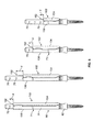
図3Aは、本発明の一実施形態による圧縮/伸延システム100を開示している。図3Bの分解図に示されているように、システム100は、ブレード−スクリュー60のそれぞれの通路装置31に係合可能な一組の開創ブレード102を備えている。また、システム100は、ブレード−スクリュー60にしっかりと係合されてかつブレード−スクリュー60内に嵌入されることが可能なシャフト104を備えている。シャフト104は、操作装置106に係合可能になっている。操作装置106は、接続要素30が接続された椎骨を変位させるために、シャフト104を互いに向かう方または互いに離れる方に移動させるように構成されている。従って、シャフト104は、体外に位置する操作装置から体内の椎骨に接続された接続要素30に変位力(例えば、圧縮力および/または伸延力)を伝達し、これによって、椎骨を互いに対して変位させる拡張器を構成している。操作装置106は、シャフト104に係合してシャフト104を互いに対して変位せるのに適するどのような形態を有していてもよい。一実施形態では、図3Aおよび図3Bに示されているように、操作装置106は、ラック110によって互いに移動可能に接続された2つのアーム108,109を備えている。各アーム108,109は、ラック110に接続された近位端112およびシャフト104の1つに係合可能な遠位端114を有している。一例では、遠位端114は、各々、開口116を備えているとよい。開口116は、該開口116を通るシャフト104の該当する1つをしっかりと受け入れるように形作られ、かつ寸法決めされている。図3Aに示されているように、開口116は、各々、シャフト104が内部に配置された状態にある通路装置31の該当する1つをしっかりと受け入れるように形作られ、かつ寸法決めされている。アーム108,109の一方または両方は、ラック110に旋回可能に接続されているとよく、この旋回は、該当する作動機構(図示せず)によって制御されるようになっているとよい。さらに、一方のアーム108がラック110の長さに沿って移動することができるようにラック110に平行移動可能に接続される一方、他のアーム109がラック110の一端に固定位置を有するようになっているとよい。平行移動アーム108は、駆動機構118を作動させることによって、ラック110に沿って移動するようになっているとよい。駆動機構118は、アーム108に接続された歯付きピニオンを回転させ、該ピニオンをラック110の対応する歯に沿って前進させるようになっているとよい。
FIG. 3A discloses a compression /
シャフト104は、各々、遠位部120および近位部122を有している。遠位部120は、接続要素30に近接する箇所において該当するアクセス装置31内に配置可能になっており、かつ接続要素30に直接的または間接的に固定可能になっているとよい。図3Bに示されているように、遠位部120は、シャフト104を接続要素30に対して固定するためのネジ部124を備えているとよい。ネジ部124は、接続要素30のネジ山68に係合するようになっていてもよいし、前述したように、接続要素30に固定された通路装置31の低ネジ山70に係合するようになっていてもよい。また、シャフト104は、ネジ部124が接続要素30のネジ山68に沿って少なくとも部分的に延在すると共に、通路装置31の低ネジ山70に沿って少なくとも部分的に延在するように、配置されていてもよい。各シャフト104の遠位部120は、ネジ部124の遠位側に延在する遠位延長部126も備えているとよい。遠位延在部126は、ネジ部124がネジ山68および/またはネジ山70に固定されたとき、スクリュー32のヘッド35に係合するように、構成されているとよい。ネジ部124をネジ山68および/またはネジ山70に沿って前進させることによって、遠位延在部126は、スクリュー32のヘッド35を強制的に押圧することになる。この強制的係合は、望ましくは、シャフト104を接続要素30に固定するのを助長する。また、この係合は、スクリュー32のヘッド35を該ヘッド35が受け入れられるケージ42に対して押し込み、これによって、望ましくは、スクリュー32に対するケージ42の多軸運動を係止することになる。
Each
好ましくは、各シャフト104の近位部122は、操作装置106の該当するアーム108,109と係合するための係合部128を備えている。係合部128は、該当するアーム108,109の開口116内にしっかりと嵌入されるように形作られ、かつ寸法決めされている。例えば、係合部分128は、通路装置31内に密嵌入されるように寸法決めされた外寸法を有しているとよい。シャフト104の幅は、それらの長さに沿って変化するようになっているとよく、これは、有利には、不要な材料を少くすることができる。これに関して、係合部128は、シャフト104の他の部分よりも広くなっているとよく、シャフト104は、係合部128の遠位側に位置するテーパ部130および係合部128の近位側に位置する他のテーパ部132を備えているとよい。
Preferably, the
図4A〜図4Cに示されているように、開創ブレード102は、各々、ブレード部134および係合部136を備えているとよい。係合部136は、開創ブレード102を通路装置31を固定するように構成されているとよい。これに関して、係合部136は、‘159出願に開示されている管状体と同様、通路装置31のブレード56を受け入れるための溝または通路を有する管状体を備えていてもよい。他の例では、図4A〜図4Cに示されているように、係合部136は、通路装置31の2つのブレード56の各1つを受け入れるための2つのブレード受容体138を備えているとよい。各ブレード受容体138は、図4Bの平面図に示されているように、ブレード56の外側の周りに延在する外側部140を備えているとよく、各ブレード受容体138は、ブレード56の内側の少なくとも一部に沿って、ブレード56の縁144の周りを包む少なくとも1つの内側延長部142(例えば、このような1つの内側延長部142がブレード56の各側に配置されている)を備えているとよい。ブレード部134に隣接する内側延長部142は、ブレード部134の厚肉部143によって画定されているとよい。厚肉部143は、ブレード56間の空間を横切って延在し、ブレード部134に隣接して両方の内側延長部142を画定している。各ブレード受容体138によって部分的に包囲された空間は、望ましくは、通路146を画定している。通路146は、通路装置31のブレード56を受け入れるように構成されている。通路146は、通路装置31の軸57と直交する面に沿って円弧形状を有しているとよく、この形状は、該面におけるブレード56の形状と実質的に一致している。内側延長部142は、望ましくは、ブレード56を通路146内に維持するように拘束するようになっている。
As shown in FIGS. 4A to 4C, the
ブレード56が通路146内に配置されたとき、開創ブレード102のブレード部134は、好ましくは、図3Aおよび図4Aに示されているように、隣接する体組織を開創するために、通路装置31に沿って位置している。これに関して、ブレード部134は、好ましくは、通路装置31の軸57を横切る方向に沿って通路装置31よりも広くなっており、ブレード部134は、その幅寸法に沿って円弧状になっているとよい。例えば、ブレード部134は、約2〜3cm幅を有しているとよく、ブレード−スクリュー60の通路装置31は、約1〜1.5cm幅を有しているとよい。また、ブレード1部34は、好ましくは、組織をブレード56間に画定された通路55に巻き込まれないようにするために、皮膚51の下方に位置する通路装置31の大部分に沿って延在している。ブレード134の遠位端148は、好ましくは、体内への開創ブレード102の挿入時に組織への外傷を低減させるために丸められている。好ましくは、開創ブレード102は、剛性であり、これによって、ブレード56が係合部136の通路内146内に配置されたとき、開創ブレード102は、ブレードを安定化させることができ、特に連結具72がブレード56に配置されていないとき、ブレード56が接続要素30から時期尚早に離脱するのを防ぐことができる。
When the
開創ブレード102が通路装置31内に完全に配置されたとき、ブレード部134の遠位端148は、図3Aに示されているように、ケージ42のアーム58の近位端54に近接して配置されるとよい。この位置によって、望ましくは、アーム58間に配置されたロッド44が、ブレード部134と干渉することなく、ケージ42を通ってかつケージ42を超えて延在することが可能になる。開創ブレード102が通路装置31に配置されているとき、該開創ブレード102を適切な位置に維持するために、開創ブレード102は、通路装置31の特徴部に係合するように形作られているとよい。例えば、係合部136の遠位端150は、図4Aに示されているように、ブレード56に沿って広幅段71に係合するようになっているとよく、この箇所において、通路装置31に沿った開創ブレード102のさらなる遠位側への運動が抑制されることになる。
When the
開創ブレード102の挿入および取外しを助長するために、ブレード部134の近位端152は、手または工具によって掴むための切抜部154を備えているとよい。また、近位端150の近くのブレード部134を通る孔156は、工具によって係合可能な特徴部を設けることによって、開創ブレード102の取外しを助長することができる。
To facilitate insertion and removal of the
図5〜図6に示されているように、本発明の実施形態によるシステムは、2つの異なる長さのブレード(すなわち、長いブレードおよび短いブレード)を有するブレード−スクリュー60を備えていてもよい。また、システムは、種々の生体構造と共に用いるために、種々の長さの開創ブレード102を備えていてもよい。システムは、ブレード−スクリュー60の長さと異なる多種類の開創ブレード長さを備えていてもよい。例えば、ブレード−スクリュー60の2つの長さを有するシステムは、図5〜図6に示されているように、4つの長さの開創ブレード102(例えば、各ブレード−スクリュー長さと共に用いられる2つの開創ブレード長さ)を有しているとよい。ブレード−スクリュー60の長いブレードが約11cm長さを有し、ブレード−スクリュー60の短いブレードが約7cm長さを有する例示的な実施形態では、前述したように、開創ブレード102の4つの長さは、約3〜4cm長さのブレード部134、約5〜6cm長さのブレード部134、約7〜8cm長さのブレード部134、および約9〜10cm長さのブレード部134を備えているとよい。2つの長さのブレード−スクリュー60しかシステムに準備されていなくてもよいが、さらなる長さの開創ブレード102によって、皮膚面51と移植された接続要素30との間に特別な距離をより緊密に調整することができる。これは、望ましい。何故なら、操作装置106のシャフト104とアーム108,109との係合の位置を下層の椎弓根の可能な限り近くに配置させることによって、操作装置106によって加えられるトルクの量を有利に低減させることができるからである。従って、開創ブレード102の適切な長さは、開創ブレード102が通路装置31に沿って十分に前進したとき、ブレード部134の近位端152が、可能な限り皮膚の近くにおいて、皮膚面51の上方に配置されるように、外科医または他のユーザーによって選択されるとよい。これによって、シャフト104と(ブレード部134の近位端152の近位側に配置された)操作装置106のアーム108,109との間の係合は、皮膚51の上方であるが、可能な限り下層の接続要素30および椎弓根に近い位置で達成されることになる。
As shown in FIGS. 5-6, a system according to an embodiment of the present invention may include a blade-
種々の長さのブレード部134を適切に配置するために、種々の長さのブレード102の各々は、開創ブレード102が通路装置31に沿って十分に前進するときにブレード部134の近位部152が段71の上方に位置する適切な距離に基づいて、図5〜図6に示されているように、異なる長さの係合部136を有しているとよい。開創ブレード102の適切な長さを決定する上で外科医または他のユーザーを支援するために、開創ブレード102は、図5に示されているように、ブレード56に沿って孔76の1つに対するブレード部134の近位端152からの距離dに基づいて画定されるとよい。付加的または代替的に、各長さのブレード部134の近位端154の位置は、図6に示されているように、シャフト104の1つまたは複数のマーク158(例えば、レーザーマーク)によって示されるとよい。図6に示されているように、種々の長さのシャフト104が、システムに準備されているとよく、ブレードシャフトの長さは、ブレード−スクリュー60の種々の長さに対応しているとよい。
In order to properly position the various lengths of the
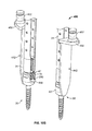
図7は、本発明の他の実施形態による圧縮/伸延システム200を開示している。システム200は、ブレード−スクリュー60のそれぞれの通路装置31および接続要素30に係合可能な一組のドッキング部材203を備えている。接続要素30が接続された椎骨を変位させるために、ドッキング部材203は、ドッキング部材203を互いに向かう方および互いから離れる方に移動させるための操作装置にも係合可能になっている。従って、ドッキング部材203は、体外に位置する操作装置から体内の椎骨に接続された接続要素30に変位力(例えば、圧縮力および/または拡張力)を伝達し、これによって、椎骨を互いに対して変位させるための拡張器を構成している。操作装置は、ドッキング部材203に係合し、ドッキング部材を互いに対して変位させるのに適するどのような形態を有していてもよい。一実施形態では、操作装置は、2つのアーム208,209を備えているとよい。アーム208,209の各々は、ドッキング部材203の1つと係合可能な遠位端214およびラック(図示せず)に接続された近位端212を有している。これは、図3A〜図3Bに示されている操作装置106のラック110と同様である。図3A〜図3Bに示されている操作装置106の実施形態におけるように、アーム208,209は、ラックに対して同様に旋回可能および平行移動可能に接続されているとよい。アーム208,209の遠位端214は、各々、それぞれのドッキング部材203のコネクター260に係合されているとよい。一例では、遠位端214は、各々、コネクター260の該当する1つをしっかりと受け入れるように形作られ、かつ寸法決めされた開口216を備えているとよい。
FIG. 7 discloses a compression /
各コネクター260は、ドッキング部材203の近位端252において外方延長部264から近位側に突出するシャフト262として構成されているとよい。図8Aに示されているように、シャフト262は、中空であるとよい。また、シャフト262は、少なくとも1つ(例えば、2つ)の柔軟タブ266を備えているとよい。柔軟タブ266の各々は、それぞれのアーム208,209の開口216内の特徴部(図示せず)にしっかりと係合するように形作られた外面268を有しているとよい。アーム208,209がコネクター260に接続されたとき、タブ266の近位端は、開口216から近位側に突出するとよい。これによって、タブ266の外面268が開口216内の特徴部から離脱するまで、タブ266を内方に押し込むことによって、アーム208,209をコネクター260から離脱させることができる。各シャフト262は、各開口216内の対応する通路272内に受け入れられるように形作られた少なくとも1つの外方突出ボス270も備えているとよい。これによって、対応するアーム208,209に対する各ドッキング部材203の回転方位が固定されることになる。
Each
各ドッキング部材203は、ブレード部234および係合部236を備えているとよい。ドッキング部203は、その遠位端274においてそれぞれの接続要素30にしっかりと係合するように構成されているとよい。これに関連して、ドッキング部材203の遠位端274は、1つまたは複数(例えば、2つ)のタブ276を備えているとよい。これらのタブ276は、図8Bに示されているように、内方に突出し、接続要素30のケージ42の外面の対応する構造と係合するように構成されているとよい。ドッキング部材203の係合部236に位置する各タブ276は、ケージ42のアーム58の縁280に沿った該当する凹部278に係合するように、構成されているとよい。タブ276は、各々、ドッキング部材203の遠位端274に形成された長孔284によって画定された柔軟プロング282に配置されているとよい。タブ276は、各々、ケージ42へのドッキング部材203の遠位端274の挿入を容易にするために、それらの遠位端に傾斜した面取り部286を有しているとよい。例えば、面取り部286は、以下のように、すなわち、ドッキング部材203の遠位端274がケージ42の近位端54に沿って遠位側に移動するとき、面取り部286がプロング282を外方に撓ませるように、構成されているとよい。ドッキング部材203のさらなる遠位側への移動によって、タブ276がケージ42の対応する凹部278に係合されることになる。いったんタブ276が凹部278内に着座したなら、ドッキング部材203の遠位端274は、好ましくは、ケージ42からのドッキング部材203の意図しない離脱を少なくともある程度抑えることになる。すなわち、タブ276の近位端の外面が、望ましくは、凹部278の近位端の外面に係合し、これによって、ドッキング部材203が近位側に移動してケージ42から離脱するのを防ぐことができる。
Each
ドッキング部材203は、好ましくは、その遠位端274が接続要素30のケージ42に係留したときに通路装置31を受け入れるように構成されている。これに関して、係合部236は、‘159出願に開示されている管状体と同じように、通路装置31のブレード56を受け入れるための溝または通路を有する管状体を備えていてもよい。他の例では、図7〜図8Aに示されているように、係合部236は、通路装置31の2つのブレード56の各1つを受け入れるための2つのブレード受容体238を備えていてもよい。ブレード受容体238は、図4Bに示されているブレード受容体138と同様または同一の構造を有しているとよい。これに関して、通路装置31の長軸57と直交する面における各ドッキング部材203の断面は、図4Bに示されている開創ブレード102の平面図と同様または同一であってもよい。係合部236が通路装置31の全体に沿って遠位側に延在し、接続要素30のケージ42に係合する実施形態では、ドッキング部材203のブレード受容体238のブレード受容通路246は、好ましくは、段71の遠位側においてブレード56の広い部分を受け入れるように形作られている。
The
ドッキング部材203をブレード−スクリュー60にさらに固定するために、ドッキング部材203のブレード受容体238は、ブレード56の長さに沿って孔76の1つに係合するために、内方に延在するボスまたは突起(図示せず)を有する柔軟タブ292を備えているとよい。各ドッキング部材203のブレード受容体238の各々が、図7に示されているように、このような1つの柔軟タブ292を備えていてもよいし、または各ドッキング部材203の両方のブレード受容体238が1つの柔軟タブ292を備えていてもよい。
In order to further secure the
ドッキング部材203がそれぞれの接続要素30に係留され、ブレード56がブレード受容体238内に配置されたとき、ドッキング部材203のブレード部234は、望ましくは、隣接する体組織を開創するために、図7に示されているように、通路装置31に沿って配置されている。これに関して、ブレード部234は、好ましくは、通路装置31の軸57を横切る方向に沿って通路装置31よりも広くなっているとよく、ブレード部234は、その幅寸法に沿って円弧状になっているとよい。例えば、ブレード部234は、約2〜3cmの幅を有しているとよく、ブレード−スクリュー60の通路装置31は、約1〜1.5cm幅を有しているとよい。また、ブレード部234は、好ましくは、組織がブレード56間に画定された通路55に巻き込まれないようにするために、皮膚51の下方に位置する通路装置31の大部分に沿って延在しているとよい。図7に示されているように、ブレード部234は、係合部236の全長にわたって延在しているとよく、これによって、ドッキング部材203の遠位端274がケージ42に係留されたとき、ブレード部234の遠位端248が接続要素30のケージ42に近接することになる。ブレード部234の遠位端248は、体内へのドッキング部材203の挿入時に組織への外傷を低減させるために、丸められているとよい。例えば、ブレード部234の遠位端248は、図4Cに示されている開創ブレード102のブレード部134の遠位端148と同じように形作られているとよい。他の例では、図8Aに示されているように、ブレード部234の遠位コーナ249が丸められていてもよい。好ましくは、ドッキング部材203は、剛性であるとよく、これによって、ブレード56がブレード受容体によって受け入れられたとき、ドッキング部材203がブレード56を安定化させることができ、特に連結具72がブレード56に配置されていないとき、ブレード56が接続要素30から時期尚早に離脱することを防ぐことができる。
When the
ドッキング部材203がケージ42に係留したとき、係合部236およびブレード部234の一方または両方が接続要素30のケージ42まで延在するようになっている実施形態では、ドッキング部材203の遠位端274は、ケージ42のアーム58間に画定された開口290と真っ直ぐに並ぶ長孔288を備えているとよい。図8Aに示されているように、長孔288は、ブレード部234の遠位端248を貫通しているとよい。望ましくは、この長孔288によって、アーム58間に配置されたロッド44は、ブレード部234と干渉することなく、開口290を通ってケージ42の外に延出することができる。
In embodiments in which one or both of the
図7〜図8Aに示されていないが、ドッキング部材203は、ドッキング部材203の挿入および取外しを助長するために、図3A〜図6の開創ブレード102におけるのと同様の切抜部および/または孔も備えているとよい。ブレード受容体238は、ドッキング部材203の近位端252において、係合部236が近位端252に管状部を形成するように、互いに接続されていてもよい。
Although not shown in FIGS. 7-8A, the
本発明の実施形態によるシステムは、システムと共に設けられる種々の長さのブレード−スクリュー60に対応するために、異なる長さのドッキング部材203を備えていてもよい。加えて、図示されていないが、図7〜図8Bの圧縮/伸延システムは、図3A〜図3Bに示されているようなシャフトと併せて用いられてもよい。このようなシャフトは、変位力を操作装置から接続要素30に伝達するために、操作装置に直接的または間接的に接続されるとよい。
Systems according to embodiments of the present invention may include different lengths of the
圧縮/伸延システムの他の実施形態(図示せず)は、ブレード部と係合部とを有する開創ブレードを備えているとよい。ブレード部は、システム100のブレード部134またはシステム200のブレード部234と同様または同一であるとよい。しかし、係合部は、通路装置31および/または接続要素30に係合するように構成されず、開創ブレードを連結具72の1つ(図1参照)に取外し可能に固定するように構成されているとよい。例えば、係合部は、開創ブレードの近位端においてクリップの形態を有しているとよい。好ましくは、このクリップは、該クリップが連結具72の1つに固定されたとき、開創ブレードの近位端が凹部78の遠位端の少なくともいくらか遠位側に位置し、これによって、前述したように、凹部78を用いて、ロッド44の賦形または選択を妨げることがないように、構成されている。望ましくは、連結具72へのこのような開創ブレードの取付けによって、ブレード56の長さに沿った連結具72に付随する開創ブレードの平行移動によって、手術中の融通性を高めることができる。このような開創ブレードは、使い捨て部品であるとよく、プラスチックまたはポリマーから構成されているとよいが、代替的に、ステンレス鋼または他の生体適合性材料から作製されていてもよい。
Another embodiment (not shown) of the compression / distraction system may include a retracting blade having a blade portion and an engagement portion. The blade portion may be similar or identical to the
圧縮/伸延システムのさらに他の実施形態では、ブレード(システム100または200のブレード部134と同様のブレード、または「脊椎手術のための器具および方法」という標題で2011年8月5日に出願された米国仮特許出願第61/515,443号(‘443出願)に開示されている開創器要素のブレードと同様のブレード)自体が、操作装置から移植された接続要素30に変位力(例えば、圧縮力または拡張力)を伝達するようになっていてもよい。‘443出願の開示内容は、参照することによって、その全体がここに完全に記載されているかのように含まれるものとする。一例では、このような圧縮/伸延システム400は、複数の開創器要素440を備えているとよく、これらの開創器要素440の各々は、‘443出願に開示されている垂直方向に細長く延びるブレードと同様のブレード部442から構成されているとよい。具体的には、図10Aに示されているように、各ブレード部442は、好ましくは、円弧状の水平断面を有しており、ブレード部442は、凸状の組織係合面444および反対側の凹面446を有している。各ブレード部442は、好ましくは、開創器要素440の遠位端447においてテーパが付されており、および/または丸められており、これによって、体内への開創器要素440の挿入時に組織の外傷を低減させることができる。各開創器要素440は、足またはシャフト448も備えているとよい。シャフト448は、好ましくは、開創器要素440の遠位端447に隣接する箇所においてブレード部442に固定され、そこから外方に(例えば、直角に)延在する短い円筒ロッドの形態にある。各開創器要素440の近位端449は、外方延長部またはブラケット450を備えているとよい。ブラケット450は、ユニットとしてブレード部442と一体に形成されているとよい。ブラケット450は、開創器要素440の近位端449に隣接する箇所において、ブレード部442から外方に(例えば、直角に)延在しているとよい。操作装置に接続されるコネクター452が、図10Aに示されているように、各開創器要素440の近位端449において、例えば、ブラケット450上に設けられているとよい。コネクター452は、例えば、ポストの形態を有していてもよいし、または前述したシステム200のコネクター260の形態を有していてもよい。図10A〜図10Bに示されていないが、開創器要素440は、開創器要素440の挿入および取外しを助長するために、図3A〜図6の開創ブレード102におけるのと同様の切抜部および/または孔を備えていてもよい。
In yet another embodiment of the compression / distraction system, a blade (a blade similar to the
各開創器要素440のシャフト448は、好ましくは、(ケージ42のアーム58間に画定された開口290内に嵌入されるように設計された)脊椎固定ロッド44の直径と同じ直径を有している。これによって、開創器要素440は、図10Bに示されているように、シャフト448を接続要素30のケージ42の各開口290内に配置し、止めネジ45をケージ42のネジ山68に沿って前進させ、これによって、シャフト448、従って、各開創器要素440をケージ42に固定することによって、各接続要素30にしっかりと係合されることになる。開創器要素440がこのように接続要素30に係合されたとき、開創器要素440のブレード部442は、好ましくは、隣接する体組織を開創するために、図10Bに示されているように、各通路装置31に沿って配置されることになる。これに関して、各ブレード部442は、好ましくは、通路装置31の軸57を横切る方向に沿って通路装置31よりも広くなっている。例えば、ブレード部442は、約2〜3cm幅を有しているとよく、ブレード−スクリュー60の通路装置31は、約1〜1.5cm幅を有しているとよい。
The
望ましくは、止めネジ45を開創器要素440のシャフト448に対してしっかりと前進させることによって、シャフト448がスクリュー32の該当するヘッド35を遠位側に強く押し込む。この強制的な係合によって、各スクリュー32のヘッド35は、該ヘッド35が嵌入されているケージ42に対して押し込まれ、これによって、望ましくは、スクリュー32に対するケージ42の多軸運動が係止されることになる。例えば、各スクリュー32のヘッド35の近位端は、各ケージ42の開口290の遠位端の上方に延在しているとよく、これによって、開口290内に位置するシャフト448(またはロッド44)の遠位側への移動が、スクリューヘッド35をシャフト448(またはロッド44)とケージ42の内面との間にクランプすることになる。接続要素30の多軸運動のこの係止は、椎骨を圧縮または伸延するとき、特に望ましい。
Desirably, the
開創器要素440は、コネクター452によって、操作装置(図示せぜ)に係合可能になっており、これによって、操作装置は、接続要素30が接続された椎骨を変位させるために、開創器要素440を互いに向かってまたは互いから離れるように移動させることができる。従って、開創器要素440は、体外に配置された操作装置から体内の椎骨に接続された接続要素30に変位力(例えば、圧縮力および/または伸延力)を伝達させ、これによって椎骨を互いに変位させるための拡張器を構成している。操作装置は、開創器要素440に係合して開創器要素440を互いに対して変位させるのに適するどのような形態を有していてもよい。例えば、操作装置は、前述した操作装置106,206の形態を有していてもよい。
The
本発明の実施形態によるシステムは、該システムと共に設けられる種々の長さのブレード−スクリュー60に対応するために、種々の長さの開創器要素440を備えているとよい。
Systems according to embodiments of the present invention may include
圧縮/伸延システム(例えば、図3A〜図6のシステム100、図7〜図8Bのシステム200、または図10Aおよび図10Bのシステム400)のいずれも、付加的な組織開創と併せて用いられてもよい。すなわち、ブレード部134,234,442によってもたらされる組織開創に加えて、付加的な開創器ブレードが用いられてもよい。例えば、図9に略示されているように、システム100、システム200,およびシステム400のいずれかまたは全てと共に用いられる操作装置306は、互いに隣接する2つのブレード−スクリュー60間に配置された中間開創器ブレード334を備えていてもよい。中間開創器ブレード334は、中間アーム307によって支持されているとよい。中間アーム307は、図9に示されているように、アーム308,309間に配置されているとよい。アーム308,309は、ブレード−スクリュー60に直接的に連結されていてもよいし、または間接的に連結されていてもよい。中間アーム307は、操作装置306のラック310を横切る方向に延在しているとよい。中間アーム307は、中間アーム307の軸に沿って(すなわち、内/外軸20に沿って)中間開創器ブレード334を移動させるように構成されているとよく、および/または中間開創器ブレード334は、旋回可能になっているとよく、これによって、ブレード334の近位端と比べて体組織をより大きく開創するようにブレード334の遠位端を構成することができる。中間アーム307は、手術部位の補助的な照明をもたらすための光源を支持するようになっているとよい。例えば、図11Aおよび図11Bに示されているように、中間開創器ブレード334は、1つまたは複数のコネクター394(例えば、中間開創器ブレード334の近位端の各側の1つのコネクター394)を備えているとよい。コネクター394は、図11Bに示されているように、照明要素396からの光を外科部位に案内するために、照明要素396(例えば、光ファイバー照明要素)の遠位端を受け入れるように構成された中空の円筒部品として形作られているとよい。操作装置306は、必ずしも図9に示されているように構成されていなくてもよく、ブレード−スクリュー60に(直接的または間接的に)係合してブレード−スクリュー60を互いに対して変位させる一方、中間開創器造ブレード334をそれらのブレード−スクリュー60間に設けるのに適するどのような構造が用いられてもよい。中間開創器ブレード334を有するこのような操作装置306は、椎体間固定術、例えば、PLIFまたはTLIFを行うときに、特に有利である。
Any of the compression / distraction systems (eg,
本発明の実施形態による例示的な方法では、前述したように、少なくとも2つのブレード−スクリュー60が体内に挿入され、隣接する椎骨に接続されるとよい。次いで、前述した圧縮/伸延システム(例えば、システム100,200,または400)が、以下のように、ブレード−スクリュー60に接続されるとよい。
In an exemplary method according to an embodiment of the present invention, as described above, at least two blade-
まず、圧縮/伸延システム100または200のいずれかの場合、前述したように、シャフト104がそれぞれのブレード−スクリュー60内に挿入され、かつ螺合される。最初、スクリュー32に対するケージ42の多軸運動をまだ係止させないために、シャフト104は、十分に前進されないとよい。これによって、有利には、ブレード−スクリュー60は、所望の位置に移動および/または傾斜し、隣接する組織を部分的に開創し、または隣接する開創された組織に対して所望の輪郭を画定することができる。ブレード−スクリュー60のこのような運動および/または傾斜は、操作装置の作動によってもたらされるとよい。次いで、接続要素30が接続された椎骨を伸延する前に、スクリュー32に対するケージ42の多軸運動を係止するために、シャフト104が十分に前進されるとよい。しかし、特に圧縮/伸延システム200を用いるとき、必ずしもシャフト104がブレード−スクリュー60内に挿入される必要がない。
First, in either of the compression /
また、適切な長さの構成部品が、外科医または他のユーザーによって選択されるとよい。例えば、患者の特定の生体構造に対して適切な長さを有するそれぞれのブレード部134,234,442を有する開創ブレード102,ドッキング部材203,または開創器要素440が、選択されるとよい。
Also, the appropriate length components may be selected by the surgeon or other user. For example, a
圧縮/伸延システム100の場合、開創ブレード102がブレード−スクリュー60の通路装置31上を適切な位置まで前進されるとよい。ブレード部134は、図3Aに示されているように、望ましくは、互いに離れるように配置されているが、各ブレード部134は、ケージ42およびケージ42が接続されたブレード56と共に、各スクリュー52を中心として所望の方位に回転されるようになっているとよい。次いで、操作装置106のアーム108,109が、シャフト104にしっかりと係合されるとよい。
In the case of the compression /
圧縮/伸延システム200の場合、ドッキング部材203は、図7に示されているように、ブレード−スクリュー60の通路装置31の全体にわたって挿入され、ブレード部234が互いに離れて配置した状態で、接続要素30にしっかりと係合されるとよい。ドッキング部材203は、コネクター260に取り付けられたアーム208,209に挿入されてもよいし、またはドッキング部材203が挿入された後、操作装置がコネクター260に係合されてもよい。
In the case of the compression /
圧縮/伸延システム400の場合、開創器要素440は、シャフト448がケージ42の開口290内に受け入れられるような位置まで前進され、この後、止めネジ45を一組または複数組の止めネジドライバーによってケージ42内に前進させることによって、ケージ42内に固定されるとよい。開創器要素440がこのように接続要素30に係合されたとき、開創器要素440のブレード部442は、図10Bに示されているように、各通路装置31に沿って配置されるとよい。しかし、通路装置31は、ブレード部442に沿って配置されなくてもよい。例えば、通路装置31は、開創器要素440が接続要素30に係合して配置される前または後に、各接続要素30から離脱されてもよい。いずれの場合も、ブレード部442は、接続要素30の近くにおける組織開創の実質的に全てをもたらすことになる。ブレード部442は、望ましくは、図10Bに示されているように、互いに離れるように配置されるとよいが、各開創要素440は、該開創器要素440が接続されたケージと共に、各スクリュー52を中心として所望の方位に回転されるようになっているとよい。次いで、操作装置のアームが、コネクター452にしっかりと係合されるとよい。
In the case of the compression /
圧縮/伸延システムが設置される前または後に、ブレード−スクリュー60の一方から他方に延在する切口Iが形成されてもよい。次いで、中間開創器ブレード334が、ブレード−スクリュー60間の切口I内に配置されるとよい。最初、中間開創器ブレード334が切口I内に配置され、次いで、中間アーム307に接続されてもよいし、またはブレード334が取り付けられた中間アーム307が、ブレード334が切口I内に配置されるように、ラック310に接続されてもよい。中間開創器ブレード334が切口I内に配置される前または後に、照明要素396が中間開創器ブレード334のコネクター394に接続されてもよい。切口I内に配置された後、中間開創器ブレード334は、切口Iを拡げ、2つのブレード−スクリュー50が接続された椎骨間の椎間板を含む脊椎10の一部を露出させるために、移動されるとよい。例えば、中間アーム307は、内/外軸20に沿って(例えば、ラック310に向かって)中間開創器ブレード334を移動させるとよく、および/または中間開創器ブレード334は、ブレード334の遠位端がブレード334の近位端に近接する体組織の開創の程度よりも大きい程度に脊椎10に近接する体組織を開創するように、旋回されるとよい。中間開創器ブレード334を切口I内に配置している最中におよび/またはブレード334によって切口Iを拡げている最中に、組織および筋肉の掃引および開創を助長するために、(コブエレベータのような)追加的な工具が用いられてもよい。切口Iは、望ましくは、中間開創器ブレード334とブレード部134,234,または442との間に画定されている。しかし、ブレード部をブレード−スクリュー60に隣接して配置することは、必ずしも必要ではないことに留意されたい。例えば、圧縮/伸延システム100を用いるとき、図11A〜図11Bに示されているように、開創ブレード102は、用いられなくてもよい。この場合、図11Bに示されているように、外科部位の周りの組織は、ブレード−スクリュー60自体および(もし用いられるなら)中間開創器ブレード334によって開いた状態で保持されることになる。
A cut I extending from one to the other of the blade-
中間開創器ブレード334が配置される前または後に、操作装置が、ブレード−スクリュー60に接続された椎骨を互いに対して変位させるように、作動されるとよい。具体的には、椎骨は、例えば、変性した椎間板を減圧するために、および/または椎骨間への椎体間移植片の挿入のための空間を設けるために、互いに離れる方に伸延されるとよい。この伸延は、ブレード部123,234,または442をさらに引き離すことによって、ブレード−スクリュー60間の切口Iをさらに拡げるのに役立つことになる。付加的または代替的に、椎骨間の椎腔を寸法決めするのに用いられるパドル伸延器、リーマ伸延器、および/またはトライアルを用いて、椎腔の初期の伸延または完全な伸延を行い、その後、必要に応じて、操作装置を作動させて、追加的な伸延を行ってもよい。いったん所望量の伸延が達成されたなら、椎骨の位置を維持するために、操作装置を係止するとよい。
Before or after the
次いで、ブレード−スクリュー60と中間開創器ブレード334との間の切口Iを通して、PLIFまたはTLIFのような椎体間固定術が行なわれるとよい。このような椎体間固定術は、椎骨の一部(椎弓板の一部および/または椎間関節の一部)を除去するステップと、椎間板の少なくとも一部を除去するステップと、椎体間移植片を椎腔内に配置するステップと、椎腔内の1つまたは複数の位置および椎腔の周りに骨グラフト材料を施すステップと、のいくつかまたは全てを含んでいるとよい。椎体間移植片の例として、同種骨、ポリエステル・エーテル・ケトン(PEEK)、チタン、または他の生体適合性材料が挙げられる。加えて、生物製剤が椎腔内に配置されてもよい。
An interbody fusion such as PLIF or TLIF may then be performed through cut I between blade-
椎体間移植片が椎腔内に配置された後、特に椎骨が融合する間に椎骨に安定性をもたらすために、ロッド44が体内に挿入され、次いで、ケージ42内に固定されるとよい。具体的には、通路装置31によってもたらされた体組織を通る通路55を用いて、所望の輪郭を有するロッド44は、該ロッド44がケージ42間に延在するまで、移植された接続要素30のケージ42に向かって前進されるとよい。ロッド44を挿入するステップは、(開創ブレード102またはドッキング部材203を備える)圧縮/伸延システム100,200の1つの構成部品がブレード−スクリュー60を覆って適所に配置された状態で、行なわれてもよいことに留意されたい。しかし、ロッド44が設置される前に、少なくともシャフト104が除去される必要がある。例えば、シャフト104は、椎体間固定術が完了した後でロッド44が設置される前に、取り外されるとよい。圧縮/伸延システム400の場合、開創器要素440は、ロッド44を受け入れるケージ42の開口290を空けるために、(止めネジ45を最初に取り外した後に)取り外される必要がある。しかし、開創器要素440またはシャフト104が取り外された後、椎体間移植片が椎腔を保持するのに十分な安定性をもたらすべきである。
After the interbody implant is placed in the vertebral cavity, the
いったんロッド44がケージ42内に配置されたなら、止めネジ45がケージ42内に挿入されるとよい。止めネジ45は、通路装置31内に挿入され、‘159出願に開示されているような止めネジドライバーを用いて、ネジ山68および/またはネジ山70に沿って前進されるとよい。止めネジドライバーは、シャフトと、前進中にドライバーを回転させるための工具に係合するための近位駆動インターフェイスと、止めネジ45のインターフェイス(図示せず)と係合するための遠位インターフェイスと、を有しているとよい。例えば、止めネジ45は、止めネジドライバーシャフトの遠位端の対応する異形突起を受け入れるための異形凹部(例えば、六角凹部)を備えているとよい。多重止めネジドライバーが設けられてもよく、この場合、各止めネジ45は、それ自体の対応する止めネジドライバーによって挿入されるとよい。止めネジ45が挿入された後、止めネジドライバーが取り外されるとよい。
Once the
止めネジ45は、最初、ネジ山68および/またはネジ山70に沿って部分的にしか前進されないとよく、または止めネジ45の1つしかロッド44に対して完全に締付けられないとよく、これによって、椎骨は、互いに対してさらに変位することができる。具体的には、椎骨は、システム100またはシステム200のような圧縮/伸延システムを用いて、互いに向かって圧縮されるとよい。他の例では、椎骨を互いに向かって圧縮するために、‘159出願に開示されているような圧縮および伸延システムが用いられてもよい。この場合、開創ブレード102またはドッキング部材203は、このような圧縮および伸延システムを挿入する前に取り外されるとよい。もしシステム100が圧縮のために用いられるなら、シャフト104がそれぞれのブレード−スクリュー60内に再挿入され、該ブレード−スクリュー60に螺合されるとよい。代替的に、システム100を用いて、止めネジドライバーが通路装置31によって画定された通路55内に残されてもよい。止めネジドライバーは、望ましくは、操作装置のアームによる力の付与時にブレード−スクリュー60に強度をもたらすように、かつ操作装置のアームによって付与された力の少なくとも一部を接続装置30に伝達するのを助長するように構成されているとよい。例えば、止めネジドライバーは、シャフト104と同じように寸法決めされ、これによって、止めネジドライバーは、ブレード−スクリュー60の通路55内に密嵌入されることになる。従って、止めネジドライバーの遠位インターフェイスが、ブレード−スクリュー60のネジ山68および/またはネジ山70に少なくとも部分的に係合された止めネジ45のインターフェイスに係合したとき、止めネジドライバーは、操作装置のアームによって加えられた力の少なくとも一部を接続要素30に伝達することを助長することができる。他の代替例では、(前述したように)トルクレンチ、例えば、最終締付けに用いられるトルクレンチが、操作装置によって加えられた少なくともいくらかの力を伝達するために、通路55内に配置されてもよい。各トルクレンチは、シャフトと、近位駆動インターフェイスと、遠位インターフェイスとを備える止めネジドライバーと同様の構造を有しているとよい。トルクレンチは、望ましくは、トルクレンチによって止めネジ45に加えられるトルクが予選択量(例えば、8Nm(ニュートン・メータ)に制限されている。さらに他の代替例では、操作装置からの力を伝達させるために、1つの止めネジドライバーおよび1つのトルクレンチが、ブレードースクリュー60のそれぞれの通路55内に配置されてもよい。この配置は、特に「一方向」圧縮に用いられてもよい。一方向圧縮では、その圧縮中に、一方の止めネジ45が締付けられ、他方の止めネジ4が締付けられないようになっており、これによって、締付けられていない接続要素30が圧縮中にロッド44に沿って移動することになる。例えば、止めネジ45の1つがトルクレンチによって最終的に締付けられ、その後、トルクレンチは、通路55内の適所に残されてもよいし、または止めネジドライバーと置き換えられてもよい。次いで、圧縮されている椎腔の他の側の接続要素の止めネジ45が、止めネジドライバーによって、ネジ山68および/または止めネジ70に沿って部分的に挿入され、その後、止めネジドライバーは、通路55内の適所に残されてもよいし、またはトルクレンチと置き換えられてもよい。次いで、圧縮が操作装置を用いて行なわれ、その後、締付けられていない止めネジ45が最終的に締付けられるとよい。
The
いったん椎骨がそれらの意図された位置に置かれたなら、止めネジ45が最終的に締付けられるとよい。このような最終的締付けは、制限されたトルクが加えられることを確実なものとするために、1つまたは複数のトルクレンチ(図示せず)によって行なわれるとよい。一例では、各止めネジ45は、それ自体の対応するトルクレンチによって、最終的に締付けられるとよい。トルクレンチは、椎骨を互いに向かって圧縮するステップのような1つまたは複数のステップの早い段階で挿入され、適所に維持されているとよいことに留意されたい。
Once the vertebrae have been placed in their intended positions, the
ロッド44が設置され、および/または止めネジ45が最終的に締付けられる前または後に、圧縮/伸延システムは、体から取り外されるとよい。これに関して、開創ブレード102またはドッキング要素203は、手によってまたは工具を用いて、例えば、図3A〜図6に示されているようなこれらの構成部品に設けられた切抜部154および/または孔156を用いて取り外されるとよい。トルクレンチも、体から取り外されるとよい。これによって、通路装置31をそれぞれの接続要素30から離脱させ、体から取り外すことができる。例えば、ブレード56は、脆弱部62においてブレード56の各々を接続要素30から破断させることによって、接続要素30から切り離されるとよい。ブレード−スクリュー60のブレード56を接続要素から破断させる1つの方法が、‘159出願に記載されている。代替的に、もしケージ42と別に形成されて離脱可能に接続可能なブレード56が用いられているなら、通路装置31のこれらのブレード56は、接続要素30から個別に切り離され、体から取り外されるとよい。
The compression / distraction system may be removed from the body before or after the
本明細書に記載されている種々の構成部品、例えば、開創ブレード102、シャフト104、およびドッキング部材203は、通路装置31のブレード56と相互作用するように設計されているものとして、記載および図示されているが、これらの構成部品は、種々の形式の通路装置、例えば、カニューレ、タワー、またはポータル(これらのいくつは、ブレード56を有していない)と相互作用するように設計可能であることを理解されたい。このような場合、これらの構成要素は、他の形式の通路装置と同じように相互作用するように、設計されてもよい。例えば、開創ブレード102およびドッキング部材203の係合部136,236は、それぞれ、このような他の形式の通路装置と係合するように構成されてもよく、これらの係合部の内面は、通路装置の対応する構造を受け入れるかまたは係合するための対応する種々の形状または他の構造を有していてもよい。さらに、シャフト104は、このような他の形式の通路装置内に受け入れられるように、構成されてもよい。
The various components described herein, such as the
加えて、種々の構成部品が、多数の部品または部分を有する単一構成部品として図示され、および/または記載されているが、本発明の他の実施形態では、このような部品または部分は、別々の構成部品であってもよく、これらの部品は、互いに接続されていてもよいし、または互いに接続されていなくもよいことに留意されたい。 In addition, although the various components are illustrated and / or described as a single component having multiple parts or portions, in other embodiments of the invention such components or portions are Note that they may be separate components, and these parts may or may not be connected to each other.
本明細書に記載されている種々の構成部品は、好ましくは、体内での使用に安全な材料から構成されている。一実施形態では、体内に恒久的に移植される構成要素の多く、例えば、ブレード−スクリュー60およびロッド44は、チタンまたはチタン合金から構成されているとよい。代替的な一例では、このような恒久的に移植可能な構成部品のいくつかまたは全てが、コバルト−クロム合金、例えば、Howmedica Osteonics Corp. からVITALLIUMの登録商標で市販されている材料から構成されているとよい。恒久的に移植可能な構成部品、例えば、開創ブレード102、シャフト104、ドッキング部材203、および開創器要素440を移植し、かつ操作するのに用いられる器具のいくつかまたは全て、および操作装置106,206,306の構成部品は、ステンレス鋼から完全に、殆ど、または部分的に構成されているとよい。
The various components described herein are preferably constructed from materials that are safe for use in the body. In one embodiment, many of the components that are permanently implanted in the body, such as blade-
本発明を特定の実施形態を参照して説明してきたが、これらの実施形態は、本発明の原
理および用途の単なる例示にすぎないことを理解されたい。従って、例示的実施形態に対
して多くの修正がなされてもよいこと、および添付の請求項に記載されている本発明の精
神および範囲から逸脱することなく、他の構成が考案されてもよいことを理解されたい。 なお、出願当初の特許請求の範囲の記載は以下の通りである。
請求項:1
脊椎の椎骨に取り付けられた接続要素に係合するための開創器装置であって、前記接続要素は、前記接続要素に接続されてそこから長軸に沿って近位側に延在する通路装置を有しており、前記通路装置は、前記長軸の少なくとも一部に沿って延在する少なくとも1つの長手方向開口を画定している開創器装置において、
前記通路装置の少なくとも一部を受け入れるように構成された係合部と、
前記係合部に接続された開創器ブレードと、
を備えており、
前記係合部が前記通路装置を受け入れたとき、前記開創器ブレードは、前記長手方向開口の少なくとも一部を覆うように配置されるようになっている、
開創器装置。
請求項:2
前記係合部が前記通路装置を受け入れたとき、前記開創器ブレードの長さは、前記通路装置に沿って長手方向に延在し、前記開創器ブレードの幅は、前記通路装置の前記長軸を横切って延在するようになっており、前記開創器ブレードの前記幅は、前記長軸を横切る前記通路装置の幅よりも広くなっている、請求項1に記載の開創器装置。
請求項:3
前記係合部は、前記係合部が前記通路装置に沿って前記接続要素まで延在するように、前記通路装置を受け入れるように構成されている、請求項1に記載の開創器装置。
請求項:4
前記係合部の遠位端は、前記接続要素にしっかりと係合するように構成されている、請求項3に記載の開創器装置。
請求項:5
前記開創器装置の近位端は、操作装置によって係合されるためのコネクターを備えている、請求項4に記載の開創器装置。
請求項:6
前記通路装置は、第1のブレードおよび第2のブレードを備えており、前記第1および第2のブレードの各々は、前記接続要素に接続される遠位端およびそこから近位側に延在する近位端を有しており、前記係合部は、前記第1および第2のブレードのそれぞれを受け入れるように構成された第1のブレード受容体および第2のブレード受容体を備えている、請求項1に記載の開創器装置。
請求項:7
前記係合部の外面は、前記第1および第2のブレード受容体間の第2の長手方向開口を画定している、請求項6に記載の開創器装置。
請求項:8
開創システムであって、
請求項6に記載の前記開創器装置と、
前記第1および第2のブレードを有する前記通路装置と、
を備えている、システム、
請求項:9
前記第1および第2のブレードの少なくとも1つは、段においてその幅が変化しており、 前記第1および第2のブレード受容体が前記第1および第2のブレードのそれぞれを受け入れたとき、前記係合部の遠位端は、前記段に係合可能になっている、請求項8に記載のシステム。
請求項:10
前記係合部が前記通路装置を受け入れたとき、前記開創器ブレードの遠位端は、前記接続要素の近位端に近接して配置されるようになっている、請求項1に記載の開創器装置。
請求項:11
前記開創器ブレードの遠位端は、丸められている、請求項1に記載の開創器装置。
請求項:12
前記開創器ブレードの遠位端は、長孔を有しており、前記係合部が前記通路装置を受け入れたとき、前記長孔は、前記接続要素の開口と真っ直ぐに並ぶようになっている、請求項1に記載の開創器装置。
請求項:13
前記開創器装置の近位部は、手によって把持されるように形作られた少なくとも1つの把持部を備えている、請求項1に記載の開創器装置。
請求項:14
前記開創器ブレードは、円弧形状を有している、請求項1に記載の開創器装置。
請求項:15
前記開創器ブレードの長手方向長さは、前記係合部の長手方向長さよりも長くなっている、請求項1に記載の開創器装置。
請求項:16
開創システムであって、
請求項1に記載の前記開創器装置と、
前記脊椎の第2の椎骨に取り付けられた第2の接続要素に係合するための第2の開創器装置であって、前記第2の接続要素は、前記第2の接続要素に接続されてそこから近位側に第2の長軸に沿って延在する第2の通路装置を有しており、前記第2の通路装置は、前記第2の長軸の少なくとも一部に沿って延在する少なくとも1つの第2の長手方向開口を画定しており、前記第2の開創器装置は、
第2の通路装置の少なくとも一部を受け入れるように構成された第2の係合部と、
前記第2の係合部に接続された第2の開創器ブレードと、
を備えており、
前記第2の係合部が前記通路装置を受け入れたとき、前記第2の開創器ブレードは、前記第2の長手方向開口の少なくとも一部を覆うように配置されるようになっている、
第2の開創器装置と、
前記通路装置内に受入れ可能な第1のシャフトであって、前記第1のシャフトの遠位部は、前記接続要素に近接して配置されており、前記第1のシャフトの近位部は、操作装置によって係合可能になっている第1のシャフトと、
前記第2の通路装置内に受入れ可能な第2のシャフトであって、前記第2のシャフトの遠位部は、前記第2の接続要素に近接して配置されており、前記第2のシャフトの近位部は、操作装置によって係合可能になっている第2のシャフトと、
を備えており、
前記第1および第2のシャフトは、前記接続要素および前記第2の接続要素のそれぞれに十分な力を伝達し、前記操作装置によってもたらされる前記第1および第2のシャフトの相対的変位に応じて、前記椎骨を前記第2の椎骨に対して変位させるように構成されている、
開創システム。
請求項:17
前記第1のシャフトの前記遠位端は、ネジ部を備えており、前記ネジ部は、前記接続要素または前記通路装置のネジ山に係合可能になっている、請求項16に記載の開創システム。
請求項:18
前記操作装置をさらに備えている、請求項16に記載のシステム。
請求項:19
開創システムであって、
脊椎のそれぞれの椎骨に取り付けられたそれぞれの接続要素に係合するための複数の開創器装置であって、前記接続要素の各々は、前記接続要素に接続されてそこから長軸に沿って近位側に延在する通路装置を有しており、前記通路装置の各々は、前記それぞれの長軸の少なくとも一部に沿って延在する少なくとも1つの長手方向開口を画定しており、前記開創器装置の各々は、
前記通路装置の少なくとも一部を受け入れるように構成された係合部と、
前記係合部に接続された開創器ブレードと、
を備えており、
前記係合部が前記通路装置を受け入れたとき、前記開創器ブレードは、前記長手方向開口の少なくとも一部を覆うように配置されるようになっている、
複数の開創器装置
を備えており、
前記複数の開創器装置の1つの前記開創器ブレードの長手方向長さは、前記複数の開創器装置の異なる1つの前記開創器ブレードの長手方向長さと異なっている、
開創システム。
請求項:20
前記通路装置の各1つ内に受入れ可能な複数のシャフトをさらに備えており、前記複数のシャフトの各1つの遠位部は、それぞれの接続要素に近接して配置されており、前記複数のシャフトの各1つの近位端は、操作装置によって係合可能になっている、請求項19に記載の開創システム。
請求項:21
前記シャフトの少なくとも1つは、複数のマークを備えており、前記複数のマークは、各々、前記複数の開創造器装置の1つの長手方向長さに対応している、請求項20に記載の開創システム。
請求項:22
体内の組織を変位させる方法であって、
第1の接続要素を前記体内の脊椎の第1の椎骨に接続するステップであって、前記第1の接続要素は、前記第1の接続要素に接続されてそこから第1の長軸に沿って近位側に延在する第1の通路装置を有しており、前記第1の通路装置は、前記第1の長軸の少なくとも一部に沿って延在する第1の長手方向開口を画定しているステップと、
第2の接続要素を前記脊椎の第2の椎骨に接続するステップであって、前記第2の接続要素は、前記第2の接続要素に接続されてそこから第2の長軸に沿って近位側に延在する第2の通路装置を有しており、前記第2の通路装置は、前記第2の長軸の少なくとも一部に沿って延在する第2の長手方向開口を画定しているステップと、
第1の開創器ブレードを前記第1の長手方向開口の少なくとも一部に沿って配置するステップと、
第2の開創器ブレードを前記第2の長手方向開口の少なくとも一部に沿って配置するステップと、
を含んでいる、方法。
請求項:23
前記第1の開創器ブレードを配置する前記ステップは、前記第1の開創器ブレードを前記第1の通路装置に連結することを含んでおり、前記第2の開創器ブレードを配置する前記ステップは、前記第2の開創器ブレードを前記第2の通路装置に連結することを含んでいる、請求項22に記載の方法。
請求項:24
前記第1の開創器ブレードを前記第1の通路装置に連結することは、前記第1の開創器ブレードに接続された第1の係合部によって前記第1の通路装置の少なくとも一部を受け入れることを含んでおり、前記第2の開創器ブレードを前記第2の通路装置に連結することは、前記第2の開創器ブレードに接続された第2の係合部によって前記第2の通路装置の少なくとも一部を受け入れることを含んでいる、請求項23に記載の方法。
請求項:25
前記第1および第2の通路装置間に延在する前記体の皮膚に開口を形成することをさらに含んでいる、請求項22に記載の方法。
請求項:26
前記第1および第2の通路装置間に位置する中間開創器ブレードによって、前記開口を拡大することをさらに含んでいる、請求項25に記載の方法。
請求項:27
椎体間移植片を前記開口を通して前記第1および第2の椎骨間の椎腔内に挿入することをさらに含んでいる、請求項25に記載の方法。
請求項:28
脊椎固定ロッドの少なくとも一部を前記第1および第2の通路装置の少なくとも1つ内において移動させることと、
前記脊椎固定ロッドを前記第1および第2の接続要素に固定することと、
をさらに含んでいる、請求項27に記載の方法。
請求項:29
前記第1および第2の椎骨を互いに対して変位させるために、第1の拡張器を第2の拡張器に対して変位させることをさらに含んでおり、
前記第1の拡張器の遠位端は、前記第1の接続要素に係合され、前記第2の拡張器の遠位端は、前記第2の接続要素に係合されるようになっている、請求項22に記載の方法。
請求項:30
前記第1の拡張器は、第1のシャフトを備えており、前記第2の拡張器は、第2のシャフトを備えており、前記方法は、
前記第1のシャフトの少なくとも一部を前記第1の接続要素の第1のケージ内に固定することと、
前記第2のシャフトの少なくとも一部を前記第2の接続要素の第2のケージ内に固定することと、
をさらに含んでいる、請求項29に記載の方法。
請求項:31
前記第1のシャフトの少なくとも一部を前記第1のケージ内に固定する前記ステップは、前記第1のシャフトが前記第1の長軸に沿って前記第1の通路装置内に延在するように、前記第1のシャフトの遠位部を前記第1のケージ内に固定することを含んでおり、 前記第2のシャフトの少なくとも一部を前記第2のケージ内に固定する前記ステップは、前記第2のシャフトが前記第2の長軸に沿って前記第2の通路装置内に延在するように、前記第2のシャフトの遠位部を前記第2の接続要素の前記第2のケージ内に固定することを含んでいる、請求項30に記載の方法。
請求項:32
前記第1のシャフトの少なくとも一部を前記第1のケージ内に固定する前記ステップは、前記第1のシャフトが前記第1の長軸を横切って延在するように、前記第1のシャフトを第1の止めネジによって前記第1のケージ内に固定することを含んでおり、前記第2のシャフトの少なくとも一部を前記第2の接続要素の前記第2のケージ内に固定する前記ステップは、前記第2のシャフトが前記第2の長軸を横切って延在するように、前記第2のシャフトを第2の止めネジによって前記第2の接続要素の前記第2のケージ内に固定することを含んでいる、請求項30に記載の方法。
請求項:33
前記第1の拡張器は、前記第1の開創器ブレードと一体に形成されており、前記第2の拡張器は、前記第2の開創器ブレードと一体に形成されている、請求項32に記載の方法。
請求項:34
椎体を変位させる方法であって、
第1の拡張器の遠位端を脊椎の第1の椎骨に取り付けられた第1の接続要素の第1のケージ内に固定するステップと、
第2の拡張器の遠位端を脊椎の第2の椎骨に取り付けられた第2の接続要素の第2のケージ内に固定するステップと、
前記第1の拡張器を前記第1の拡張器に対して変位させ、前記第1および第2の椎骨を互いに対して変位させるステップと、
を含んでいる、方法。
請求項:35
前記第1の接続要素は、第1の椎弓根スクリューを備えており、前記第2の接続要素は、第2の椎弓根スクリューを備えている、請求項34に記載の方法。
請求項:36
前記第1のケージは、前記第1の椎弓根スクリューに多軸連結されており、前記第2のケージは、前記第2の椎弓根スクリューに多軸連結されている、請求項35に記載の方法。
請求項:37
前記第1の拡張器の前記遠位端を前記第1のケージ内に固定する前記ステップは、前記第1の椎弓根スクリューに対する前記第1のケージの多軸運動を係止するようになっており、前記第2の拡張器の前記遠位端を前記第2のケージ内に固定する前記ステップは、前記第2の椎弓根スクリューに対する前記第2のケージの多軸運動を係止するようになっている、請求項36に記載の方法。
請求項:38
前記第1の拡張器は、第1のシャフトを備えており、前記第2の拡張器は、第2のシャフトを備えている、請求項34に記載の方法。
請求項:39
前記第1の接続要素は、前記第1の接続要素に接続されてそこから第1の長軸に沿って近位側に延在する第1の通路装置を有しており、前記第2の接続要素は、前記第2の接続要素に接続されてそこから第2の長軸に沿って近位側に延在する第2の通路装置を有しており、前記第1の拡張器の前記遠位端を前記第1のケージ内に固定することは、前記第1のシャフトが前記第1の長軸に沿って前記第1の通路装置内に延在するように、前記第1のシャフトの遠位端を前記第1のケージ内に固定することを含んでおり、前記第2の拡張器の前記遠位端を前記第2のケージ内に固定することは、前記第2のシャフトが前記第2の長軸に沿って前記第2の通路装置内に延在するように、前記第2のシャフトの遠位部を前記第2のケージ内に固定することを含んでいる、請求項38に記載の方法。
請求項:40
前記第1の拡張器の前記遠位端を前記第1のケージ内に固定することは、前記第1のシャフトが前記第1の拡張器の長軸を横切って延在するように、前記第1のシャフトを第1の止めネジによって前記第1のケージ内に固定することを含んでおり、前記第2の拡張器の前記遠位端を前記第2のケージ内に固定することは、前記第2のシャフトが前記第2の拡張器の長軸を横切って延在するように、前記第2のシャフトを第2の止めネジによって前記第2のケージ内に固定することを含んでいる、請求項38に記載の方法。
請求項:41
前記第1の拡張器は、第1の開創器ブレードと一体に形成されており、前記第2の拡張器は、第2の開創器ブレードと一体に形成されている、請求項40に記載の方法。
請求項:42
椎体を変位させるためのシステムであって、
近位端および遠位端を有する第1の拡張器であって、前記第1の拡張器の前記遠位端は、脊椎の第1の椎骨に取付け可能な第1の接続要素の第1のケージ内にしっかりと係合されるように構成されている第1の拡張器と、
近位端および遠位端を有する第2の拡張器であって、前記第2の拡張器の前記遠位端は、前記脊椎の第2の椎骨に取付け可能な第2の接続要素の第2のケージ内にしっかりと係合されるように構成されている第2の拡張器と、
前記第1および第2の拡張器に係合可能な操作装置であって、前記操作装置は、前記第1および第2の拡張器がそれぞれ前記取り付けられた第1および第2の接続要素にしっかりと係合されたとき、前記第2の拡張器に対する前記第1の拡張器の移動をもたらすことによって、前記第1および第2の椎骨を互いに対して変位させるように構成されている操作装置と、
を備えている、システム。
請求項:43
前記第1の拡張器は、第1のシャフトを備えており、前記第1のシャフトの少なくとも一部は、前記第1のケージ内にしっかりと係合されるように構成されており、前記第2の拡張器は、第2のシャフトを備えており、前記第2のシャフトの少なくとも一部は、前記第2のケージ内にしっかりと係合されるように構成されている、請求項42に記載のシステム。
請求項:44
前記第1の接続要素は、前記第1の接続要素に接続されてそこから第1の長軸に沿って近位側に延在する第1の通路装置を有しており、前記第1のシャフトは、前記第1の通路装置内に前記第1の長軸に沿って受入れ可能となっており、前記第2の接続要素は、前記第2の接続要素に接続されてそこから第2の長軸に沿って近位側に延在する第2の通路装置を有しており、前記第2のシャフトは、前記第2の通路装置内に前記第2の長軸に沿って受入れ可能となっている、請求項43に記載のシステム。
請求項:45
前記第1のシャフトの遠位部は、前記第1の接続要素または前記第1の通路装置のネジ山と係合可能なネジ部を備えている、請求項44に記載のシステム。
請求項:46
前記第1のシャフトは、前記第1の拡張器の長軸を横切って延在しており、前記第1のシャフトは、第1の止めネジによって前記第1のケージ内にしっかりと係合されるように構成されており、前記第2のシャフトは、前記第2の拡張器の長軸を横切って延在しており、前記第2のシャフトは、第2の止めネジによって前記第2のケージ内にしっかりと係合されるように構成されている、請求項43に記載のシステム。
請求項:47
前記第1の拡張器は、第1の開創器ブレードと一体に形成されており、前記第2の拡張器は、第2の開創器ブレードと一体に形成されている、請求項46に記載のシステム。
Although the invention has been described with reference to particular embodiments, it is to be understood that these embodiments are merely illustrative of the principles and applications of the present invention. Accordingly, many modifications can be made to an exemplary embodiment and other configurations can be devised without departing from the spirit and scope of the invention as set forth in the appended claims. Please understand that. The description of the claims at the beginning of the application is as follows.
Claim: 1
A retractor device for engaging a connecting element attached to a vertebra of a spine, wherein the connecting element is connected to the connecting element and extends proximally therefrom along a long axis A retractor device, wherein the passage device defines at least one longitudinal opening extending along at least a portion of the longitudinal axis;
An engagement portion configured to receive at least a portion of the passage device;
A retractor blade connected to the engagement portion;
With
The retractor blade is arranged to cover at least a portion of the longitudinal opening when the engagement portion receives the passage device;
Retractor device.
Claims: 2
When the engagement portion receives the passage device, the length of the retractor blade extends longitudinally along the passage device, and the width of the retractor blade is equal to the major axis of the passage device. The retractor device of
Claim: 3
The retractor device of
Claims: 4
The retractor device of claim 3, wherein a distal end of the engagement portion is configured to securely engage the connecting element.
Claim: 5
The retractor device of claim 4, wherein a proximal end of the retractor device comprises a connector for engagement by an operating device.
Claim: 6
The passage device comprises a first blade and a second blade, each of the first and second blades extending distally and proximally connected to the connecting element. And the engagement portion includes a first blade receiver and a second blade receiver configured to receive each of the first and second blades. The retractor device of
Claims: 7
The retractor device of claim 6, wherein an outer surface of the engagement portion defines a second longitudinal opening between the first and second blade receivers.
Claim: 8
A creative system,
The retractor device of claim 6;
The passage device having the first and second blades;
Equipped with the system,
Claim: 9
At least one of the first and second blades has a width that varies in a step, and when the first and second blade receivers receive the first and second blades, respectively, The system of claim 8, wherein a distal end of the engagement portion is engageable with the step.
Claim: 10
The retractor according to
Claim: 11
The retractor device of
Claim: 12
The distal end of the retractor blade has a slot, and when the engagement portion receives the passage device, the slot is aligned with the opening of the connecting element. The retractor device of
Claim: 13
The retractor device of
Claim: 14
The retractor device of
Claim: 15
The retractor device according to
Claims: 16
A creative system,
The retractor device of
A second retractor device for engaging a second connection element attached to a second vertebra of the spine, wherein the second connection element is connected to the second connection element; Proximal to it is a second passage device extending along a second major axis, the second passage device extending along at least a portion of the second major axis. Defining at least one second longitudinal opening present, said second retractor device comprising:
A second engagement portion configured to receive at least a portion of the second passage device;
A second retractor blade connected to the second engagement portion;
With
The second retractor blade is arranged to cover at least a portion of the second longitudinal opening when the second engagement portion receives the passage device;
A second retractor device;
A first shaft receivable within the passage device, wherein a distal portion of the first shaft is disposed proximate to the connecting element, and a proximal portion of the first shaft is A first shaft that is engageable by an operating device;
A second shaft receivable within the second passage device, the distal portion of the second shaft being disposed proximate to the second connecting element, the second shaft A proximal portion of the second shaft that is engageable by the operating device;
With
The first and second shafts transmit sufficient force to the connection element and the second connection element, respectively, in response to the relative displacement of the first and second shafts provided by the operating device. And configured to displace the vertebra with respect to the second vertebra,
Creation system.
Claims: 17
The retractor according to
Claims: 18
The system according to
Claim: 19
A creative system,
A plurality of retractor devices for engaging respective connecting elements attached to respective vertebrae of the spine, each of said connecting elements being connected to said connecting element and proximate along a longitudinal axis therefrom; Each of the passage devices defines at least one longitudinal opening extending along at least a portion of the respective major axis, and the retractor Each of the equipment is
An engagement portion configured to receive at least a portion of the passage device;
A retractor blade connected to the engagement portion;
With
The retractor blade is arranged to cover at least a portion of the longitudinal opening when the engagement portion receives the passage device;
With multiple retractor devices,
The longitudinal length of one retractor blade of the plurality of retractor devices is different from the longitudinal length of one different retractor blade of the plurality of retractor devices;
Creation system.
Claim: 20
A plurality of shafts receivable within each one of the passage devices, each distal portion of the plurality of shafts being disposed proximate to a respective connecting element; 20. A retractor system according to claim 19, wherein each one proximal end of the shaft is engageable by an operating device.
Claim: 21
21. The at least one of the shafts comprises a plurality of marks, each of the plurality of marks corresponding to one longitudinal length of the plurality of retractor devices. Creation system.
Claim: 22
A method of displacing tissue in the body,
Connecting a first connecting element to a first vertebra of the spine in the body, the first connecting element connected to the first connecting element and from there along a first major axis And a first passage device extending proximally, the first passage device having a first longitudinal opening extending along at least a portion of the first major axis. Defining steps;
Connecting a second connecting element to a second vertebra of the spine, wherein the second connecting element is connected to the second connecting element and is proximate along a second major axis therefrom. A second passage device extending to the distal side, the second passage device defining a second longitudinal opening extending along at least a portion of the second major axis. And steps
Positioning a first retractor blade along at least a portion of the first longitudinal opening;
Positioning a second retractor blade along at least a portion of the second longitudinal opening;
Including the way.
Claim: 23
The step of positioning the first retractor blade includes coupling the first retractor blade to the first passage device, and the step of positioning the second retractor blade includes 23. The method of
Claims: 24
Coupling the first retractor blade to the first passage device receives at least a portion of the first passage device by a first engagement portion connected to the first retractor blade. Connecting the second retractor blade to the second passage device by means of a second engagement portion connected to the second retractor blade. 24. The method of
Claim: 25
23. The method of
Claim: 26
26. The method of
Claims: 27
26. The method of
Claim: 28
Moving at least a portion of a spinal fixation rod within at least one of the first and second passage devices;
Securing the spinal fixation rod to the first and second connecting elements;
28. The method of claim 27, further comprising:
Claims: 29
Displacing the first dilator relative to the second dilator to displace the first and second vertebrae relative to each other;
The distal end of the first dilator is engaged with the first connection element, and the distal end of the second dilator is engaged with the second connection element. 23. The method of
Claim: 30
The first dilator comprises a first shaft, the second dilator comprises a second shaft, and the method comprises:
Securing at least a portion of the first shaft within a first cage of the first connecting element;
Securing at least a portion of the second shaft within a second cage of the second connecting element;
30. The method of claim 29, further comprising:
Claims: 31
The step of securing at least a portion of the first shaft within the first cage is such that the first shaft extends into the first passage device along the first major axis. Securing the distal portion of the first shaft within the first cage, the step of securing at least a portion of the second shaft within the second cage comprising: The distal portion of the second shaft is connected to the second of the second connecting element such that the second shaft extends along the second major axis into the second passage device. 32. The method of
Claims: 32
The step of securing at least a portion of the first shaft within the first cage includes disposing the first shaft such that the first shaft extends across the first major axis. Securing in the first cage by a first set screw, the step of securing at least a portion of the second shaft in the second cage of the second connecting element; The second shaft is secured within the second cage of the second connecting element by a second set screw such that the second shaft extends across the second major axis. 32. The method of
Claims: 33
The first dilator is integrally formed with the first retractor blade, and the second dilator is integrally formed with the second retractor blade. The method described.
Claims: 34
A method of displacing a vertebral body,
Securing the distal end of the first dilator within the first cage of the first connecting element attached to the first vertebra of the spine;
Securing the distal end of the second dilator within the second cage of the second connecting element attached to the second vertebra of the spine;
Displacing the first dilator relative to the first dilator and displacing the first and second vertebrae relative to each other;
Including the way.
Claims: 35
35. The method of
Claim: 36
36. The method of
Claim: 37
The step of securing the distal end of the first dilator within the first cage locks the multi-axis movement of the first cage relative to the first pedicle screw. And the step of securing the distal end of the second dilator within the second cage locks the multi-axis movement of the second cage relative to the second pedicle screw. 40. The method of
Claim: 38
35. The method of
Claim: 39
The first connecting element includes a first passage device connected to the first connecting element and extending proximally therefrom along a first major axis; and The connecting element has a second passage device connected to the second connecting element and extending proximally therefrom along a second major axis, the connecting element of the first dilator Securing a distal end within the first cage may include the first shaft such that the first shaft extends into the first passage device along the first major axis. Securing the distal end of the second dilator in the second cage, the securing of the distal end of the second dilator in the second cage is performed by the second shaft. A distal portion of the second shaft is secured within the second cage so as to extend into the second passage device along the second major axis. It contains bets The method of
Claim: 40
Securing the distal end of the first dilator in the first cage is such that the first shaft extends across the long axis of the first dilator. Securing a shaft in the first cage with a first set screw, and securing the distal end of the second dilator in the second cage comprises: Securing the second shaft within the second cage by a second set screw such that the second shaft extends across the major axis of the second dilator. 40. The method of
Claims: 41
41. The first dilator is formed integrally with a first retractor blade and the second dilator is formed integrally with a second retractor blade. Method.
Claims: 42
A system for displacing a vertebral body,
A first dilator having a proximal end and a distal end, wherein the distal end of the first dilator is a first connecting element first attachable to a first vertebra of the spine. A first dilator configured to be securely engaged within the cage;
A second dilator having a proximal end and a distal end, wherein the distal end of the second dilator is second of a second connecting element attachable to a second vertebra of the spine. A second dilator configured to be securely engaged within the cage of
An operating device engagable with the first and second dilators, the operating device being secured to the first and second connecting elements to which the first and second dilators are respectively attached. An operating device configured to displace the first and second vertebrae relative to each other by causing movement of the first dilator relative to the second dilator when engaged with ,
System.
Claim: 43
The first dilator includes a first shaft, and at least a portion of the first shaft is configured to be securely engaged within the first cage; 43. The dilator of
Claims: 44
The first connecting element has a first passage device connected to the first connecting element and extending proximally therefrom along a first major axis; A shaft is receivable along the first major axis into the first passage device, and the second connecting element is connected to the second connecting element and from there a second A second passage device extending proximally along a major axis, wherein the second shaft is receivable along the second major axis within the second passage device; 44. The system of claim 43, wherein:
Claims: 45
45. The system of
Claim: 46
The first shaft extends across the long axis of the first dilator, and the first shaft is securely engaged within the first cage by a first set screw. The second shaft extends across the long axis of the second dilator, and the second shaft is coupled to the second shaft by a second set screw. 44. The system of claim 43, wherein the system is configured to be securely engaged within a cage.
Claims: 47
49. The first dilator is formed integrally with a first retractor blade, and the second dilator is formed integrally with a second retractor blade. system.
Claims (20)
前記通路装置の少なくとも一部を受け入れるように構成された係合部と、
前記係合部に接続された開創器ブレードであって、前記開創器ブレードの長手方向長さは、前記係合部の長手方向長さよりも長くなっている、開創器ブレードと、
を備えており、
前記係合部が前記通路装置を受け入れたとき、前記開創器ブレードは、前記開創器ブレードの堅固な部分が前記長手方向開口の少なくとも一部を覆うように配置されるようになっている、
開創器装置。 A retractor device for engaging a connecting element attached to a vertebra of a spine, wherein the connecting element is connected to the connecting element and extends proximally therefrom along a long axis The passage device defines an at least partially sealed tubular space configured to receive a spinal fixation rod, the passage device having at least one longitudinal length within the tubular space. A retractor device defining a directional opening, wherein the longitudinal opening extends along at least a portion of the long axis;
An engagement portion configured to receive at least a portion of the passage device;
A retractor blade connected to the engagement portion , wherein the retractor blade has a longitudinal length longer than a longitudinal length of the engagement portion ;
With
The retractor blade is arranged such that a rigid portion of the retractor blade covers at least a portion of the longitudinal opening when the engagement portion receives the passage device;
Retractor device.
請求項6に記載の前記開創器装置と、
前記第1および第2のブレードを有する前記通路装置と、
を備えている、システム、 A creative system,
The retractor device of claim 6;
The passage device having the first and second blades;
Equipped with the system,
請求項1に記載の前記開創器装置と、The retractor device of claim 1;
前記脊椎の第2の椎骨に取り付けられた第2の接続要素に係合するための第2の開創器装置であって、前記第2の接続要素は、前記第2の接続要素に接続されてそこから近位側に第2の長軸に沿って延在する第2の通路装置を有しており、前記第2の通路装置は、前記第2の長軸の少なくとも一部に沿って延在する少なくとも1つの第2の長手方向開口を画定しており、前記第2の開創器装置は、A second retractor device for engaging a second connection element attached to a second vertebra of the spine, wherein the second connection element is connected to the second connection element; Proximal to it is a second passage device extending along a second major axis, the second passage device extending along at least a portion of the second major axis. Defining at least one second longitudinal opening present, said second retractor device comprising:
第2の通路装置の少なくとも一部を受け入れるように構成された第2の係合部と、A second engagement portion configured to receive at least a portion of the second passage device;
前記第2の係合部に接続された第2の開創器ブレードと、A second retractor blade connected to the second engagement portion;
を備えており、With
前記第2の係合部が前記通路装置を受け入れたとき、前記第2の開創器ブレードは、前記第2の長手方向開口の少なくとも一部を覆うように配置されるようになっている、第2の開創器装置と、The second retractor blade is arranged to cover at least a portion of the second longitudinal opening when the second engagement portion receives the passage device; Two retractor devices;
前記通路装置内に受入れ可能な第1のシャフトであって、前記第1のシャフトの遠位部は、前記接続要素に近接して配置されており、前記第1のシャフトの近位部は、操作装置によって係合可能になっている第1のシャフトと、A first shaft receivable within the passage device, wherein a distal portion of the first shaft is disposed proximate to the connecting element, and a proximal portion of the first shaft is A first shaft that is engageable by an operating device;
前記第2の通路装置内に受入れ可能な第2のシャフトであって、前記第2のシャフトの遠位部は、前記第2の接続要素に近接して配置されており、前記第2のシャフトの近位部は、操作装置によって係合可能になっている第2のシャフトと、A second shaft receivable in the second passage device, the distal portion of the second shaft being disposed proximate to the second connecting element, the second shaft A proximal portion of the second shaft that is engageable by the operating device;
を備えており、With
前記第1および第2のシャフトは、前記接続要素および前記第2の接続要素のそれぞれに十分な力を伝達し、前記操作装置によってもたらされる前記第1および第2のシャフトの相対的変位に応じて、前記椎骨を前記第2の椎骨に対して変位させるように構成されている、The first and second shafts transmit sufficient force to the connection element and the second connection element, respectively, in response to the relative displacement of the first and second shafts provided by the operating device. And configured to displace the vertebra with respect to the second vertebra,
開創システム。Creation system.
脊椎のそれぞれの椎骨に取り付けられたそれぞれの接続要素に係合するための複数の開創器装置であって、前記接続要素の各々は、前記接続要素に接続されてそこから長軸に沿って近位側に延在する通路装置を有しており、前記通路装置の各々は、脊椎固定ロッドを受け入れるように構成された少なくとも部分的に密閉された管状空間を画定しており、前記通路装置の各々は、前記それぞれの管状空間内に少なくとも1つの長手方向開口を画定しており、前記長手方向開口は、前記それぞれの長軸の少なくとも一部に沿って延在しており、
前記開創器装置の各々は、
前記通路装置の少なくとも一部を受け入れるように構成された係合部と、
前記係合部に接続された開創器ブレードであって、前記開創器ブレードの長手方向長さは、前記係合部の長手方向長さよりも長くなっている、開創器ブレードと、
を備えており、
前記係合部が前記通路装置を受け入れたとき、前記開創器ブレードは、前記開創器ブレードの堅固な部分が前記長手方向開口の少なくとも一部を覆うように配置されるようになっている、
複数の開創器装置
を備えており、
前記複数の開創器装置の1つの前記開創器ブレードの前記長手方向長さは、前記複数の開創器装置の異なる1つの前記開創器ブレードの前記長手方向長さと異なっている、開創システム。 A creative system,
A plurality of retractor devices for engaging respective connecting elements attached to respective vertebrae of the spine, each of said connecting elements being connected to said connecting element and proximate along a longitudinal axis therefrom; A passage device extending distally, each of the passage devices defining an at least partially sealed tubular space configured to receive a spinal fixation rod ; Each defines at least one longitudinal opening in the respective tubular space, the longitudinal opening extending along at least a portion of the respective long axis;
Each of the retractor devices
An engagement portion configured to receive at least a portion of the passage device;
A retractor blade connected to the engagement portion, wherein the retractor blade has a longitudinal length longer than a longitudinal length of the engagement portion;
With
The retractor blade is arranged such that a rigid portion of the retractor blade covers at least a portion of the longitudinal opening when the engagement portion receives the passage device;
Multiple retractor devices
With
The retracting system, wherein the longitudinal length of one retractor blade of the plurality of retractor devices is different from the longitudinal length of one different retractor blade of the plurality of retractor devices .
Applications Claiming Priority (2)
| Application Number | Priority Date | Filing Date | Title |
|---|---|---|---|
| US201361915635P | 2013-12-13 | 2013-12-13 | |
| US61/915,635 | 2013-12-13 |
Related Child Applications (1)
| Application Number | Title | Priority Date | Filing Date |
|---|---|---|---|
| JP2019000939A Division JP6728411B2 (en) | 2013-12-13 | 2019-01-08 | Tissue retracting and vertebral displacement devices, systems and methods for posterior spinal fusion |
Publications (3)
| Publication Number | Publication Date |
|---|---|
| JP2015128581A JP2015128581A (en) | 2015-07-16 |
| JP2015128581A5 JP2015128581A5 (en) | 2017-11-30 |
| JP6465638B2 true JP6465638B2 (en) | 2019-02-06 |
Family
ID=52101166
Family Applications (2)
| Application Number | Title | Priority Date | Filing Date |
|---|---|---|---|
| JP2014251968A Expired - Fee Related JP6465638B2 (en) | 2013-12-13 | 2014-12-12 | Tissue retraction and vertebral displacement device, system, and method for posterior spinal fusion |
| JP2019000939A Expired - Fee Related JP6728411B2 (en) | 2013-12-13 | 2019-01-08 | Tissue retracting and vertebral displacement devices, systems and methods for posterior spinal fusion |
Family Applications After (1)
| Application Number | Title | Priority Date | Filing Date |
|---|---|---|---|
| JP2019000939A Expired - Fee Related JP6728411B2 (en) | 2013-12-13 | 2019-01-08 | Tissue retracting and vertebral displacement devices, systems and methods for posterior spinal fusion |
Country Status (5)
| Country | Link |
|---|---|
| US (4) | US9622795B2 (en) |
| EP (2) | EP2898836B1 (en) |
| JP (2) | JP6465638B2 (en) |
| AU (3) | AU2014274626B2 (en) |
| CA (2) | CA2874390C (en) |
Families Citing this family (61)
| Publication number | Priority date | Publication date | Assignee | Title |
|---|---|---|---|---|
| US8172855B2 (en) | 2004-11-24 | 2012-05-08 | Abdou M S | Devices and methods for inter-vertebral orthopedic device placement |
| US8992558B2 (en) | 2008-12-18 | 2015-03-31 | Osteomed, Llc | Lateral access system for the lumbar spine |
| CN102821673B (en) * | 2009-11-10 | 2016-06-08 | 纽瓦西弗公司 | Retractor systems |
| US8764806B2 (en) | 2009-12-07 | 2014-07-01 | Samy Abdou | Devices and methods for minimally invasive spinal stabilization and instrumentation |
| US8845728B1 (en) | 2011-09-23 | 2014-09-30 | Samy Abdou | Spinal fixation devices and methods of use |
| US20130226240A1 (en) | 2012-02-22 | 2013-08-29 | Samy Abdou | Spinous process fixation devices and methods of use |
| US9198767B2 (en) | 2012-08-28 | 2015-12-01 | Samy Abdou | Devices and methods for spinal stabilization and instrumentation |
| US9320617B2 (en) | 2012-10-22 | 2016-04-26 | Cogent Spine, LLC | Devices and methods for spinal stabilization and instrumentation |
| US9770272B2 (en) | 2012-12-12 | 2017-09-26 | Wright Medical Technology, Inc. | Orthopedic compression/distraction device |
| JP2017506939A (en) * | 2014-01-29 | 2017-03-16 | スパイナル・ユーエスエー・インコーポレーテッド | Minimally invasive devices and systems and methods for treating the spine |
| US10285680B2 (en) * | 2014-02-18 | 2019-05-14 | Globus Medical, Inc. | Retracting tissue |
| EP3449854B1 (en) * | 2014-03-14 | 2020-07-08 | Wright Medical Technology, Inc. | Orthopedic compression/distraction device |
| FR3018678B1 (en) * | 2014-03-20 | 2016-03-11 | Spineway | SURGICAL ASSEMBLY, BONE ANCHORING SCREW AND DEVICE FOR EXTENSION OF SUCH SCREWS FORMING PART OF SAID SURGICAL ASSEMBLY |
| US10172601B2 (en) * | 2014-04-22 | 2019-01-08 | University Hospitals Cleveland Medical Center | Spine retractor |
| US11160666B2 (en) * | 2014-05-15 | 2021-11-02 | Globus Medical, Inc. | Laterally insertable intervertebral spinal implant |
| JP6475449B2 (en) * | 2014-09-18 | 2019-02-27 | 賢 石井 | Spine surgery instrument |
| US10028772B2 (en) * | 2014-10-07 | 2018-07-24 | Alphatec Spine, Inc. | Osteotomy instrument |
| EP3100687B1 (en) * | 2015-06-04 | 2021-07-21 | Minimal Invasive Technologies (Pty) Ltd | Pedicle mountable retractor system |
| AU2016274981A1 (en) | 2015-06-11 | 2018-01-18 | Howmedica Osteonics Corp. | Spine-anchored targeting systems and methods for posterior spinal surgery |
| DE102015212050B3 (en) * | 2015-06-29 | 2016-08-18 | Silony Medical International AG | 3 Apparatus for performing distraction or compression of vertebral bodies in a spinal surgery |
| US9700293B2 (en) * | 2015-08-18 | 2017-07-11 | Globus Medical, Inc. | Devices and systems for surgical retraction |
| US10857003B1 (en) | 2015-10-14 | 2020-12-08 | Samy Abdou | Devices and methods for vertebral stabilization |
| US9924932B2 (en) * | 2015-12-01 | 2018-03-27 | Seth K. WILLIAMS | Technique and system for lateral lumbar spine fusion |
| US11166709B2 (en) | 2016-08-23 | 2021-11-09 | Stryker European Operations Holdings Llc | Instrumentation and methods for the implantation of spinal implants |
| DE102016118718A1 (en) * | 2016-10-04 | 2018-04-05 | Zbigniew Combrowski | Surgical instrument |
| US10973648B1 (en) | 2016-10-25 | 2021-04-13 | Samy Abdou | Devices and methods for vertebral bone realignment |
| US10744000B1 (en) | 2016-10-25 | 2020-08-18 | Samy Abdou | Devices and methods for vertebral bone realignment |
| US10779866B2 (en) * | 2016-12-29 | 2020-09-22 | K2M, Inc. | Rod reducer assembly |
| WO2018144988A1 (en) * | 2017-02-03 | 2018-08-09 | K2M, Inc. | Retractor blade including a pair of clips |
| CN110267610B (en) * | 2017-02-17 | 2023-02-21 | 华沙整形外科股份有限公司 | Surgical systems and methods |
| US11191533B2 (en) * | 2017-04-23 | 2021-12-07 | Retrospine Pty Ltd | Retraction assembly for surgery |
| EP3415107B1 (en) * | 2017-06-12 | 2021-08-04 | Biedermann Technologies GmbH & Co. KG | Bone anchor |
| US10973558B2 (en) | 2017-06-12 | 2021-04-13 | K2M, Inc. | Screw insertion instrument and methods of use |
| US11020102B2 (en) | 2017-07-10 | 2021-06-01 | K2M, Inc. | Swivel retractor and rigid connection system for retractors |
| US11413028B2 (en) | 2017-10-18 | 2022-08-16 | Spine Wave, Inc. | Screw-based retractor having arms with plural discrete selectively lockable positions |
| US10363022B2 (en) | 2017-10-18 | 2019-07-30 | Spine Wave, Inc. | Screw based retractor with expandable blades |
| EP3517062B1 (en) * | 2018-01-26 | 2021-03-17 | Aesculap AG | Spinal repositioning instrument and spinal repositioning system |
| US11191532B2 (en) | 2018-03-30 | 2021-12-07 | Stryker European Operations Holdings Llc | Lateral access retractor and core insertion |
| US10959859B2 (en) * | 2018-07-25 | 2021-03-30 | Warsaw Orthopedic, Inc. | Spinal implant system and method |
| US11179248B2 (en) | 2018-10-02 | 2021-11-23 | Samy Abdou | Devices and methods for spinal implantation |
| US11413029B2 (en) | 2018-10-24 | 2022-08-16 | Stryker European Operations Holdings Llc | Anterior to psoas instrumentation |
| US10660631B1 (en) | 2018-12-13 | 2020-05-26 | Invictus Development & Engineering, Inc. | Pedicle screw mounted retractor system |
| US11065065B2 (en) * | 2019-02-22 | 2021-07-20 | Warsaw Orthopedic, Inc. | Spinal implant system and methods of use |
| EP3930607A4 (en) * | 2019-02-27 | 2022-12-14 | Lenkbar LLC | Spinal fixation assembly |
| US20220202405A1 (en) * | 2019-04-23 | 2022-06-30 | Warsaw Orthopedic, Inc. | Surgical system and method |
| US20220218395A1 (en) * | 2019-04-23 | 2022-07-14 | Warsaw Orthopedic, Inc. | Surgical system and method |
| US20220202450A1 (en) * | 2019-04-23 | 2022-06-30 | Warsaw Orthopedic, Inc. | Surgical system and method |
| CN113710175A (en) * | 2019-04-23 | 2021-11-26 | 华沙整形外科股份有限公司 | Surgical system and method |
| EP3958760A4 (en) * | 2019-04-23 | 2022-12-07 | Warsaw Orthopedic, Inc. | Surgical system and method |
| US10893894B2 (en) * | 2019-04-24 | 2021-01-19 | Aesculap Implant Systems, Llc | Transverse coupling for surgical implant extensions |
| CN110507453B (en) * | 2019-08-30 | 2021-10-29 | 中国人民解放军北部战区总医院 | Intervertebral restorer |
| US11564674B2 (en) | 2019-11-27 | 2023-01-31 | K2M, Inc. | Lateral access system and method of use |
| US11134994B2 (en) * | 2020-01-30 | 2021-10-05 | Warsaw Orthopedic, Inc. | Spinal-correction system having threaded extender tabs and reduction tab extenders |
| US11439442B2 (en) * | 2020-04-16 | 2022-09-13 | Warsaw Orthopedic, Inc. | Modular screw system with head locker and derotator |
| US11617602B2 (en) * | 2020-04-16 | 2023-04-04 | Medtronic, Inc. | Systems, methods of use and surgical instruments employing a secure slide lock to fasten a head |
| EP4259007A1 (en) | 2020-12-09 | 2023-10-18 | Alphatec Spine, Inc. | Surgical retractors |
| US11350922B1 (en) * | 2021-02-03 | 2022-06-07 | Warsaw Orthopedic, Inc. | Modular surgical instrument system and method for shank-based retraction and distraction |
| US11432852B1 (en) * | 2021-03-22 | 2022-09-06 | Warsaw Orthopedic, Inc. | Screw shank based tissue retraction |
| WO2023009587A1 (en) * | 2021-07-29 | 2023-02-02 | Skaggs Dr David | Systems and methods for treatment of spinal deformities |
| CN113907860B (en) * | 2021-09-14 | 2023-03-31 | 郑州大学第一附属医院 | Auxiliary positioning device for embedding sacroiliac screw |
| US11737795B1 (en) * | 2022-02-28 | 2023-08-29 | Globus Medical, Inc. | System and methods for rod insertion using a screw tower |
Family Cites Families (107)
| Publication number | Priority date | Publication date | Assignee | Title |
|---|---|---|---|---|
| US3002802A (en) | 1958-01-22 | 1961-10-03 | Philips Corp | Amplifier for electrically heated stylus |
| US3002798A (en) | 1958-10-30 | 1961-10-03 | Corley Clifton | Toothbrush holder and paste dispenser |
| US3052720A (en) | 1961-07-06 | 1962-09-04 | Tesi Giorgio | Preparation of bis(trifluoromethyl) phosphinous amide |
| GB1519139A (en) | 1974-06-18 | 1978-07-26 | Crock H V And Pericic L | L securing elongate members to structurs more especially in surgical procedures |
| CH639264A5 (en) | 1979-09-11 | 1983-11-15 | Synthes Ag | Instrument used for the treatment of vertebral fractures and scoliosis |
| US4409968A (en) | 1980-02-04 | 1983-10-18 | Drummond Denis S | Method and apparatus for engaging a hook assembly to a spinal column |
| US4411259A (en) | 1980-02-04 | 1983-10-25 | Drummond Denis S | Apparatus for engaging a hook assembly to a spinal column |
| DE3414374C2 (en) | 1984-04-16 | 1986-12-18 | Patrick Dr. 3590 Bad Wildungen Kluger | Device for setting up a spine with damaged vertebral bodies |
| DE3711091A1 (en) | 1987-04-02 | 1988-10-13 | Kluger Patrick | DEVICE FOR SETTING UP A SPINE WITH A DAMAGED SPINE |
| USRE36221E (en) | 1989-02-03 | 1999-06-01 | Breard; Francis Henri | Flexible inter-vertebral stabilizer as well as process and apparatus for determining or verifying its tension before installation on the spinal column |
| JPH0620466B2 (en) | 1989-03-31 | 1994-03-23 | 有限会社田中医科器械製作所 | Spinal column correction device |
| US5059194A (en) | 1990-02-12 | 1991-10-22 | Michelson Gary K | Cervical distractor |
| US5219349A (en) | 1991-02-15 | 1993-06-15 | Howmedica, Inc. | Spinal fixator reduction frame |
| US5584887A (en) | 1991-08-15 | 1996-12-17 | Smith & Nephew Richards, Inc. | Percutaneous screw adapter |
| US5242443A (en) | 1991-08-15 | 1993-09-07 | Smith & Nephew Dyonics, Inc. | Percutaneous fixation of vertebrae |
| US5545228A (en) | 1991-08-15 | 1996-08-13 | Smith & Nephew Richards Inc. | Offset bone bolt |
| DE4127303A1 (en) | 1991-08-17 | 1993-02-18 | Aesculap Ag | FIXATEUR INTERNAL FOR REPOSITION OF A LUMBAL SPONDYLOLISTHESIS |
| US5167662A (en) | 1992-01-24 | 1992-12-01 | Zimmer, Inc. | Temporary clamp and inserter for a posterior midline spinal clamp |
| DE4202748A1 (en) | 1992-01-31 | 1993-08-05 | Kluger Patrick | SPINAL IMPLANT AND REPOSITION INSTRUMENTS |
| DE9202745U1 (en) | 1992-03-02 | 1992-04-30 | Howmedica Gmbh, 2314 Schoenkirchen, De | |
| US5281223A (en) | 1992-09-21 | 1994-01-25 | Ray R Charles | Tool and method for derotating scoliotic spine |
| US5487743A (en) | 1994-02-15 | 1996-01-30 | Sofamore, S.N.C. | Anterior dorso-lumbar spinal osteosynthesis instrumentation for the correction of kyphosis |
| DE19522879A1 (en) | 1995-06-23 | 1997-01-02 | Aesculap Ag | Surgical retractor |
| FR2757761B1 (en) | 1996-12-27 | 1999-08-20 | Stryker France Sa | SPINE OTEOSYNTHESIS SYSTEM WITH POSITION ADJUSTMENT |
| US6193721B1 (en) | 1997-02-11 | 2001-02-27 | Gary K. Michelson | Multi-lock anterior cervical plating system |
| US5846193A (en) | 1997-05-01 | 1998-12-08 | Wright; John T. M. | Midcab retractor |
| DE29710484U1 (en) | 1997-06-16 | 1998-10-15 | Howmedica Gmbh | Receiving part for a holding component of a spinal implant |
| DE29710979U1 (en) | 1997-06-24 | 1997-08-21 | Aesculap Ag & Co Kg | Implant for fixing bone parts and tool for this implant |
| US5944658A (en) | 1997-09-23 | 1999-08-31 | Koros; Tibor B. | Lumbar spinal fusion retractor and distractor system |
| FR2770124B1 (en) * | 1997-10-23 | 1999-12-10 | Materiel Orthopedique En Abreg | SURGICAL INSTRUMENTATION FOR SHRINKAGE AND SPREADING OF SOFT TISSUES AND VESSELS FOR AN ANTERIOR APPROACH OF THE RACHIS |
| US6241729B1 (en) | 1998-04-09 | 2001-06-05 | Sdgi Holdings, Inc. | Method and instrumentation for posterior interbody fusion |
| US5928139A (en) | 1998-04-24 | 1999-07-27 | Koros; Tibor B. | Retractor with adjustable length blades and light pipe guides |
| US6139493A (en) | 1998-07-08 | 2000-10-31 | Koros; Tibor B. | Retractor with adjustable length blades and light pipe guides |
| US6123707A (en) | 1999-01-13 | 2000-09-26 | Spinal Concepts, Inc. | Reduction instrument |
| US6146386A (en) | 1999-02-04 | 2000-11-14 | Sdgi Holdings, Inc. | Cable operated bone anchor compressor |
| US6770096B2 (en) | 1999-07-01 | 2004-08-03 | Spinevision S.A. | Interbody spinal stabilization cage and spinal stabilization method |
| US6530929B1 (en) | 1999-10-20 | 2003-03-11 | Sdgi Holdings, Inc. | Instruments for stabilization of bony structures |
| DE50007759D1 (en) | 1999-11-25 | 2004-10-21 | Sulzer Orthopedics Ltd | Surgical instrument for tensioning a cable-like tensioning element |
| AU2726701A (en) | 1999-12-10 | 2001-06-18 | Nuvasive, Inc. | Facet screw and bone allograft intervertebral support and fusion system |
| DE10027988C2 (en) | 2000-06-06 | 2003-08-21 | Arkadiusz Kosmala | Device for stereotaxically guided percutaneous implantation of the longitudinal connection of the pedicle screws |
| US7056321B2 (en) | 2000-08-01 | 2006-06-06 | Endius, Incorporated | Method of securing vertebrae |
| US7985247B2 (en) | 2000-08-01 | 2011-07-26 | Zimmer Spine, Inc. | Methods and apparatuses for treating the spine through an access device |
| US6802844B2 (en) | 2001-03-26 | 2004-10-12 | Nuvasive, Inc | Spinal alignment apparatus and methods |
| US6648891B2 (en) | 2001-09-14 | 2003-11-18 | The Regents Of The University Of California | System and method for fusing spinal vertebrae |
| US7052497B2 (en) | 2002-08-14 | 2006-05-30 | Sdgi Holdings, Inc. | Techniques for spinal surgery and attaching constructs to vertebral elements |
| AU2002323586A1 (en) | 2002-09-05 | 2004-03-29 | Endius Incorporated | System and methods for performing minimally-invasive surgical procedures |
| CA2502571C (en) | 2002-10-30 | 2011-10-18 | Spinal Concepts, Inc. | Spinal stabilization system insertion and methods |
| US20040147928A1 (en) | 2002-10-30 | 2004-07-29 | Landry Michael E. | Spinal stabilization system using flexible members |
| US8100828B2 (en) | 2002-11-23 | 2012-01-24 | George Frey | Distraction and retraction system for spinal surgery |
| US7608096B2 (en) | 2003-03-10 | 2009-10-27 | Warsaw Orthopedic, Inc. | Posterior pedicle screw and plate system and methods |
| US7621918B2 (en) | 2004-11-23 | 2009-11-24 | Jackson Roger P | Spinal fixation tool set and method |
| DE50302889D1 (en) | 2003-04-24 | 2006-05-18 | Zimmer Gmbh Winterthur | Instrument system for pedicle screws |
| US7473267B2 (en) | 2003-04-25 | 2009-01-06 | Warsaw Orthopedic, Inc. | System and method for minimally invasive posterior fixation |
| US6945974B2 (en) | 2003-07-07 | 2005-09-20 | Aesculap Inc. | Spinal stabilization implant and method of application |
| US20050021040A1 (en) | 2003-07-21 | 2005-01-27 | Rudolf Bertagnoli | Vertebral retainer-distracter and method of using same |
| EP1667584B1 (en) | 2003-08-26 | 2008-12-10 | Zimmer Spine, Inc. | Access systems for minimally invasive surgery |
| US7955355B2 (en) | 2003-09-24 | 2011-06-07 | Stryker Spine | Methods and devices for improving percutaneous access in minimally invasive surgeries |
| US8002798B2 (en) | 2003-09-24 | 2011-08-23 | Stryker Spine | System and method for spinal implant placement |
| US7455685B2 (en) | 2003-09-29 | 2008-11-25 | Warsaw Orthopedic, Inc. | Instruments and methods for securing a connecting element along a bony segment |
| US7731737B2 (en) | 2003-10-24 | 2010-06-08 | Zimmer Spine, Inc. | Methods and apparatuses for fixation of the spine through an access device |
| US20050090822A1 (en) | 2003-10-24 | 2005-04-28 | Dipoto Gene | Methods and apparatus for stabilizing the spine through an access device |
| EP1691668A2 (en) | 2003-10-02 | 2006-08-23 | Endius Incorporated | Methods, systems and apparatuses for performing minimally invasive spinal procedures |
| US7666188B2 (en) | 2003-12-16 | 2010-02-23 | Depuy Spine, Inc. | Methods and devices for spinal fixation element placement |
| BRPI0417589A (en) | 2003-12-16 | 2007-03-20 | Depuy Spine Inc | Methods and devices for minimally invasive placement of spinal fixation |
| US7527638B2 (en) | 2003-12-16 | 2009-05-05 | Depuy Spine, Inc. | Methods and devices for minimally invasive spinal fixation element placement |
| US9050148B2 (en) | 2004-02-27 | 2015-06-09 | Roger P. Jackson | Spinal fixation tool attachment structure |
| US7776051B2 (en) | 2004-05-03 | 2010-08-17 | Theken Spine, Llc | System and method for displacement of bony structures |
| US7666189B2 (en) * | 2004-09-29 | 2010-02-23 | Synthes Usa, Llc | Less invasive surgical system and methods |
| US7811288B2 (en) | 2004-12-02 | 2010-10-12 | Zimmer Spine, Inc. | Instruments and methods for adjusting separation distance of vertebral bodies with a minimally invasive spinal stabilization procedure |
| WO2006091863A2 (en) | 2005-02-23 | 2006-08-31 | Pioneer Laboratories, Inc. | Minimally invasive surgical system |
| US7914536B2 (en) | 2005-03-11 | 2011-03-29 | Aesculap Ag | Bone repair device and method |
| US7578822B2 (en) | 2005-04-29 | 2009-08-25 | Warsaw Orthopedic, Inc. | Instrument for compression or distraction |
| US7618424B2 (en) * | 2005-04-29 | 2009-11-17 | Warsaw Orthopedic, Inc. | Orthopedic instrument |
| US8177817B2 (en) | 2005-05-18 | 2012-05-15 | Stryker Spine | System and method for orthopedic implant configuration |
| US7846093B2 (en) | 2005-09-26 | 2010-12-07 | K2M, Inc. | Minimally invasive retractor and methods of use |
| WO2007075843A2 (en) | 2005-12-19 | 2007-07-05 | Abdou M S | Devices for inter- vertebral orthopedic device placement |
| WO2007092056A1 (en) | 2006-02-06 | 2007-08-16 | Stryker Spine | Rod contouring apparatus and method for percutaneous pedicle screw extension |
| EP2066242B1 (en) | 2006-09-25 | 2011-05-04 | Stryker Spine | Percutaneous compression and distraction system |
| DE602007008112D1 (en) | 2006-09-25 | 2010-09-09 | Stryker Spine | ALIGNMENT CONNECTION FOR BAR CONTOURING |
| US8162952B2 (en) * | 2006-09-26 | 2012-04-24 | Ebi, Llc | Percutaneous instrument assembly |
| US8038699B2 (en) * | 2006-09-26 | 2011-10-18 | Ebi, Llc | Percutaneous instrument assembly |
| US8197488B2 (en) | 2006-10-16 | 2012-06-12 | Depuy Spine, Inc. | Automatic locking casper distractor |
| US8052720B2 (en) | 2006-11-09 | 2011-11-08 | Zimmer Spine, Inc. | Minimally invasive pedicle screw access system and associated method |
| US8231635B2 (en) | 2007-01-18 | 2012-07-31 | Stryker Spine | Polyaxial screwdriver for a pedicle screw system |
| US8118737B2 (en) | 2007-01-30 | 2012-02-21 | Mi4Spine, Llc | Retractor device for cervical spinal fusion |
| US8403940B2 (en) | 2007-02-19 | 2013-03-26 | Lanx, Inc. | Tool to dissect or compress and measure a vertebral body segment |
| US8210852B2 (en) | 2007-04-11 | 2012-07-03 | Pacific Research Laboratories, Inc. | Artificial bones and methods of making same |
| US8444649B2 (en) * | 2008-07-07 | 2013-05-21 | Depuy Spine, Inc. | System and method for manipulating a spinal construct |
| US8287546B2 (en) | 2008-07-31 | 2012-10-16 | Zimmer Spine, Inc. | Surgical instrument with integrated compression and distraction mechanisms |
| EP2742884B1 (en) * | 2008-10-23 | 2018-10-31 | Alphatec Spine, Inc. | Systems for spinal fixation |
| WO2010121291A1 (en) | 2009-04-19 | 2010-10-28 | Kevin Seex | Assembly for spinal surgery including cannulated retractor blade |
| US9597095B2 (en) | 2009-05-15 | 2017-03-21 | Globus Medical, Inc | Screw guide and tissue retractor instrument |
| WO2010135537A2 (en) | 2009-05-20 | 2010-11-25 | Synthes Usa, Llc | Patient-mounted retraction |
| CN102821673B (en) * | 2009-11-10 | 2016-06-08 | 纽瓦西弗公司 | Retractor systems |
| US8764806B2 (en) * | 2009-12-07 | 2014-07-01 | Samy Abdou | Devices and methods for minimally invasive spinal stabilization and instrumentation |
| EP2523608B1 (en) | 2010-01-12 | 2016-03-30 | Tedan Surgical | Surgical retractor with curved blades |
| US9307972B2 (en) * | 2011-05-10 | 2016-04-12 | Nuvasive, Inc. | Method and apparatus for performing spinal fusion surgery |
| US8585705B2 (en) * | 2011-10-18 | 2013-11-19 | Intelligent Implant Systems, Llc | Percutaneous instrumentation and surgical procedure |
| US8911442B2 (en) | 2011-10-26 | 2014-12-16 | Alphatec Spine, Inc. | Systems for vertebral adjustments and rod reduction |
| US8936599B2 (en) | 2011-11-02 | 2015-01-20 | Tenzin Llc | Translational instrumentation for spondylolisthesis and scoliosis reduction |
| US9125703B2 (en) * | 2012-01-16 | 2015-09-08 | K2M, Inc. | Rod reducer, compressor, distractor system |
| FR2990839B1 (en) | 2012-05-28 | 2015-03-06 | Safe Orthopaedics | SPINAL DEVICE COMPRISING REVERSIBLE HANGING MEANS |
| EP2705799B1 (en) * | 2012-09-06 | 2015-05-13 | Medacta International S.A. | Surgical device for minimally invasive spinal fusion and surgical system comprising the same |
| US9510875B2 (en) | 2013-03-14 | 2016-12-06 | Stryker European Holdings I, Llc | Systems and methods for percutaneous spinal fusion |
| US9402660B2 (en) * | 2013-09-05 | 2016-08-02 | Warsaw Orthopedic, Inc. | Surgical instrument and method |
| US9402661B2 (en) * | 2013-09-23 | 2016-08-02 | Stryker European Holdings I, LCC | Lumbar-sacral screw insertion and manipulation |
| US9408716B1 (en) | 2013-12-06 | 2016-08-09 | Stryker European Holdings I, Llc | Percutaneous posterior spinal fusion implant construction and method |
-
2014
- 2014-12-12 JP JP2014251968A patent/JP6465638B2/en not_active Expired - Fee Related
- 2014-12-12 US US14/569,013 patent/US9622795B2/en active Active
- 2014-12-12 CA CA2874390A patent/CA2874390C/en active Active
- 2014-12-12 AU AU2014274626A patent/AU2014274626B2/en active Active
- 2014-12-12 CA CA2992336A patent/CA2992336C/en active Active
- 2014-12-15 EP EP14197996.3A patent/EP2898836B1/en active Active
- 2014-12-15 EP EP20152805.6A patent/EP3659525B1/en active Active
-
2017
- 2017-03-22 US US15/466,302 patent/US10507046B2/en active Active
-
2019
- 2019-01-08 JP JP2019000939A patent/JP6728411B2/en not_active Expired - Fee Related
- 2019-12-16 US US16/715,006 patent/US11622793B2/en active Active
-
2020
- 2020-02-14 AU AU2020201092A patent/AU2020201092B2/en active Active
-
2022
- 2022-03-02 AU AU2022201443A patent/AU2022201443B2/en active Active
-
2023
- 2023-03-30 US US18/128,724 patent/US20230233235A1/en active Pending
Also Published As
| Publication number | Publication date |
|---|---|
| CA2874390C (en) | 2018-03-06 |
| EP3659525A1 (en) | 2020-06-03 |
| US11622793B2 (en) | 2023-04-11 |
| US20230233235A1 (en) | 2023-07-27 |
| CA2992336C (en) | 2020-04-14 |
| AU2022201443B2 (en) | 2024-05-23 |
| EP2898836A1 (en) | 2015-07-29 |
| JP2015128581A (en) | 2015-07-16 |
| US20170189080A1 (en) | 2017-07-06 |
| EP3659525B1 (en) | 2023-12-20 |
| US10507046B2 (en) | 2019-12-17 |
| AU2014274626A1 (en) | 2015-07-02 |
| US20200113606A1 (en) | 2020-04-16 |
| CA2992336A1 (en) | 2015-06-13 |
| CA2874390A1 (en) | 2015-06-13 |
| US20150164569A1 (en) | 2015-06-18 |
| JP6728411B2 (en) | 2020-07-22 |
| JP2019093158A (en) | 2019-06-20 |
| AU2014274626B2 (en) | 2019-12-12 |
| US9622795B2 (en) | 2017-04-18 |
| AU2020201092A1 (en) | 2020-03-05 |
| AU2020201092B2 (en) | 2021-12-02 |
| EP2898836B1 (en) | 2020-01-22 |
| AU2022201443A1 (en) | 2022-03-24 |
Similar Documents
| Publication | Publication Date | Title |
|---|---|---|
| JP6465638B2 (en) | Tissue retraction and vertebral displacement device, system, and method for posterior spinal fusion | |
| US10603026B2 (en) | Devices and systems for surgical retraction | |
| JP4481301B2 (en) | Guide wire insertion device | |
| US10980528B2 (en) | Devices and systems for surgical retraction | |
| US7909829B2 (en) | Tissue retractor and drill guide | |
| JP4564006B2 (en) | Spine stabilization implant and method for applying | |
| JP6340221B2 (en) | Percutaneous spinal cross-linking system and method | |
| US20130150864A1 (en) | Surgical instrument and method | |
| US20160220278A1 (en) | System and method for spinal fusion | |
| US20240009003A1 (en) | Instrument holder assemblies and retractors for spinal surgery procedures | |
| EP3503817B1 (en) | Minimally invasive surgical system | |
| WO2022198134A1 (en) | Instrument holder assemblies and retractors for spinal surgery procedures |
Legal Events
| Date | Code | Title | Description |
|---|---|---|---|
| A711 | Notification of change in applicant |
Free format text: JAPANESE INTERMEDIATE CODE: A711 Effective date: 20160219 |
|
| A521 | Request for written amendment filed |
Free format text: JAPANESE INTERMEDIATE CODE: A821 Effective date: 20160222 |
|
| A521 | Request for written amendment filed |
Free format text: JAPANESE INTERMEDIATE CODE: A523 Effective date: 20171019 |
|
| A621 | Written request for application examination |
Free format text: JAPANESE INTERMEDIATE CODE: A621 Effective date: 20171019 |
|
| A977 | Report on retrieval |
Free format text: JAPANESE INTERMEDIATE CODE: A971007 Effective date: 20180720 |
|
| A131 | Notification of reasons for refusal |
Free format text: JAPANESE INTERMEDIATE CODE: A131 Effective date: 20180803 |
|
| A521 | Request for written amendment filed |
Free format text: JAPANESE INTERMEDIATE CODE: A523 Effective date: 20181029 |
|
| TRDD | Decision of grant or rejection written | ||
| A01 | Written decision to grant a patent or to grant a registration (utility model) |
Free format text: JAPANESE INTERMEDIATE CODE: A01 Effective date: 20181109 |
|
| A601 | Written request for extension of time |
Free format text: JAPANESE INTERMEDIATE CODE: A601 Effective date: 20181210 |
|
| R155 | Notification before disposition of declining of application |
Free format text: JAPANESE INTERMEDIATE CODE: R155 |
|
| A61 | First payment of annual fees (during grant procedure) |
Free format text: JAPANESE INTERMEDIATE CODE: A61 Effective date: 20190108 |
|
| R150 | Certificate of patent or registration of utility model |
Ref document number: 6465638 Country of ref document: JP Free format text: JAPANESE INTERMEDIATE CODE: R150 |
|
| S111 | Request for change of ownership or part of ownership |
Free format text: JAPANESE INTERMEDIATE CODE: R313113 |
|
| LAPS | Cancellation because of no payment of annual fees | ||
| R350 | Written notification of registration of transfer |
Free format text: JAPANESE INTERMEDIATE CODE: R350 |