JP6457776B2 - IMAGING DEVICE AND IMAGING DEVICE CONTROL METHOD - Google Patents
IMAGING DEVICE AND IMAGING DEVICE CONTROL METHOD Download PDFInfo
- Publication number
- JP6457776B2 JP6457776B2 JP2014209957A JP2014209957A JP6457776B2 JP 6457776 B2 JP6457776 B2 JP 6457776B2 JP 2014209957 A JP2014209957 A JP 2014209957A JP 2014209957 A JP2014209957 A JP 2014209957A JP 6457776 B2 JP6457776 B2 JP 6457776B2
- Authority
- JP
- Japan
- Prior art keywords
- area
- areas
- reliability
- sub
- focus
- Prior art date
- Legal status (The legal status is an assumption and is not a legal conclusion. Google has not performed a legal analysis and makes no representation as to the accuracy of the status listed.)
- Active
Links
- 238000000034 method Methods 0.000 title claims description 73
- 238000003384 imaging method Methods 0.000 title claims description 44
- 238000001514 detection method Methods 0.000 claims description 72
- 238000005259 measurement Methods 0.000 claims description 52
- 230000003287 optical effect Effects 0.000 claims description 17
- 210000001747 pupil Anatomy 0.000 claims description 7
- 238000012545 processing Methods 0.000 description 31
- 238000011156 evaluation Methods 0.000 description 21
- 230000008569 process Effects 0.000 description 21
- 238000012790 confirmation Methods 0.000 description 10
- 230000000875 corresponding effect Effects 0.000 description 6
- 230000006870 function Effects 0.000 description 6
- 238000004891 communication Methods 0.000 description 5
- 230000001276 controlling effect Effects 0.000 description 5
- 238000007781 pre-processing Methods 0.000 description 5
- 238000006243 chemical reaction Methods 0.000 description 4
- 230000006835 compression Effects 0.000 description 4
- 238000007906 compression Methods 0.000 description 4
- 230000006837 decompression Effects 0.000 description 4
- 230000004907 flux Effects 0.000 description 4
- 239000004973 liquid crystal related substance Substances 0.000 description 4
- 230000008859 change Effects 0.000 description 3
- 238000010586 diagram Methods 0.000 description 3
- 238000003860 storage Methods 0.000 description 3
- 239000000470 constituent Substances 0.000 description 2
- 238000012937 correction Methods 0.000 description 2
- 230000009467 reduction Effects 0.000 description 2
- 238000012546 transfer Methods 0.000 description 2
- 125000002066 L-histidyl group Chemical group [H]N1C([H])=NC(C([H])([H])[C@](C(=O)[*])([H])N([H])[H])=C1[H] 0.000 description 1
- 238000013459 approach Methods 0.000 description 1
- 230000000903 blocking effect Effects 0.000 description 1
- 230000002596 correlated effect Effects 0.000 description 1
- 230000003247 decreasing effect Effects 0.000 description 1
- 238000009826 distribution Methods 0.000 description 1
- 238000000605 extraction Methods 0.000 description 1
- 238000004519 manufacturing process Methods 0.000 description 1
- 239000011159 matrix material Substances 0.000 description 1
- 238000012805 post-processing Methods 0.000 description 1
- 230000011514 reflex Effects 0.000 description 1
- 230000004044 response Effects 0.000 description 1
- 238000005070 sampling Methods 0.000 description 1
- 229920006395 saturated elastomer Polymers 0.000 description 1
- 230000001629 suppression Effects 0.000 description 1
- 230000007704 transition Effects 0.000 description 1
Images


Classifications
-
- G—PHYSICS
- G02—OPTICS
- G02B—OPTICAL ELEMENTS, SYSTEMS OR APPARATUS
- G02B7/00—Mountings, adjusting means, or light-tight connections, for optical elements
- G02B7/28—Systems for automatic generation of focusing signals
- G02B7/36—Systems for automatic generation of focusing signals using image sharpness techniques, e.g. image processing techniques for generating autofocus signals
-
- G—PHYSICS
- G01—MEASURING; TESTING
- G01B—MEASURING LENGTH, THICKNESS OR SIMILAR LINEAR DIMENSIONS; MEASURING ANGLES; MEASURING AREAS; MEASURING IRREGULARITIES OF SURFACES OR CONTOURS
- G01B11/00—Measuring arrangements characterised by the use of optical techniques
- G01B11/14—Measuring arrangements characterised by the use of optical techniques for measuring distance or clearance between spaced objects or spaced apertures
-
- G—PHYSICS
- G02—OPTICS
- G02B—OPTICAL ELEMENTS, SYSTEMS OR APPARATUS
- G02B7/00—Mountings, adjusting means, or light-tight connections, for optical elements
- G02B7/28—Systems for automatic generation of focusing signals
- G02B7/34—Systems for automatic generation of focusing signals using different areas in a pupil plane
-
- H—ELECTRICITY
- H04—ELECTRIC COMMUNICATION TECHNIQUE
- H04N—PICTORIAL COMMUNICATION, e.g. TELEVISION
- H04N23/00—Cameras or camera modules comprising electronic image sensors; Control thereof
- H04N23/60—Control of cameras or camera modules
- H04N23/67—Focus control based on electronic image sensor signals
- H04N23/672—Focus control based on electronic image sensor signals based on the phase difference signals
-
- H—ELECTRICITY
- H04—ELECTRIC COMMUNICATION TECHNIQUE
- H04N—PICTORIAL COMMUNICATION, e.g. TELEVISION
- H04N25/00—Circuitry of solid-state image sensors [SSIS]; Control thereof
- H04N25/70—SSIS architectures; Circuits associated therewith
- H04N25/703—SSIS architectures incorporating pixels for producing signals other than image signals
- H04N25/704—Pixels specially adapted for focusing, e.g. phase difference pixel sets
-
- G—PHYSICS
- G03—PHOTOGRAPHY; CINEMATOGRAPHY; ANALOGOUS TECHNIQUES USING WAVES OTHER THAN OPTICAL WAVES; ELECTROGRAPHY; HOLOGRAPHY
- G03B—APPARATUS OR ARRANGEMENTS FOR TAKING PHOTOGRAPHS OR FOR PROJECTING OR VIEWING THEM; APPARATUS OR ARRANGEMENTS EMPLOYING ANALOGOUS TECHNIQUES USING WAVES OTHER THAN OPTICAL WAVES; ACCESSORIES THEREFOR
- G03B13/00—Viewfinders; Focusing aids for cameras; Means for focusing for cameras; Autofocus systems for cameras
- G03B13/32—Means for focusing
- G03B13/34—Power focusing
- G03B13/36—Autofocus systems
Landscapes
- Physics & Mathematics (AREA)
- Engineering & Computer Science (AREA)
- General Physics & Mathematics (AREA)
- Optics & Photonics (AREA)
- Multimedia (AREA)
- Signal Processing (AREA)
- Computer Vision & Pattern Recognition (AREA)
- Studio Devices (AREA)
- Focusing (AREA)
- Automatic Focus Adjustment (AREA)
Description
本発明は、撮像素子上に形成された位相差検出画素を用いて撮影被写体の位置を測距することにより、高速、高精度にオートフォーカスを行うことが可能な撮像装置および撮像装置の制御方法に関する。 The present invention provides an imaging apparatus capable of performing autofocus with high speed and high accuracy by measuring the position of a subject to be photographed using phase difference detection pixels formed on an imaging element, and a method for controlling the imaging apparatus About.
デジタルカメラの高機能化には目を見張るものがあり、性能も日々進歩している。様々な機能により、撮影者の技量によらず品質の高い写真が撮影できるようになってきている。オートフォーカスもそれら機能の1つであり、動きのある被写体を的確に撮影するためには、被写体の位置を正確に測距し、測距した情報に基づいて被写体位置を予測し、レンズを駆動する必要がある。 There is a remarkable increase in the functionality of digital cameras, and the performance is improving day by day. With various functions, it has become possible to take high-quality photos regardless of the skill of the photographer. Autofocus is one of those functions, and in order to accurately photograph moving subjects, the subject position is accurately measured, the subject position is predicted based on the measured information, and the lens is driven. There is a need to.
オートフォーカスの方式は大別するとアクティブ方式とパッシブ方式に分類することができる。アクティブ方式はカメラから被写体に赤外線など照射して、被写体により反射された信号により被写体までの距離を測定する方式である。この方式は一部のデジタルビデオカメラなどに用いられているが、レンズ交換式デジタルカメラなどで使用されることは少ない。一方、パッシブ方式は撮像レンズを通ってきた光束に基づいて測距を行う方式であり、コントラスト方式と位相差方式に分けられる。 Autofocus methods can be broadly classified into active methods and passive methods. The active method is a method in which a subject is irradiated with infrared rays or the like from a camera, and a distance to the subject is measured by a signal reflected by the subject. This method is used in some digital video cameras, but is rarely used in interchangeable lens digital cameras. On the other hand, the passive method is a method that performs distance measurement based on the light beam that has passed through the imaging lens, and is divided into a contrast method and a phase difference method.
コントラスト方式(以下、コントラストAF)はコンパクトデジタルカメラやレンズ交換式デジタルカメラに広く用いられ、フォーカスレンズの位置を光軸に方向に移動させながら、撮像素子から画像信号を読み出し、フレーム毎に画像信号からコントラスト値(AF評価値)を算出し、コントラスト値の最大値を探索し、最大値が得られるフォーカスレンズ位置を合焦位置とする方式である。 The contrast method (hereinafter referred to as contrast AF) is widely used in compact digital cameras and interchangeable lens digital cameras. The image signal is read from the image sensor while moving the position of the focus lens in the direction of the optical axis, and the image signal for each frame. The contrast value (AF evaluation value) is calculated from the image, the maximum value of the contrast value is searched, and the focus lens position where the maximum value is obtained is set as the in-focus position.
位相差方式は撮像レンズの瞳を一対の領域に分割して、分割された瞳領域を通過する光束が形成する一対の像の相対的な位置変化を検出することによって、合焦位置を検出方式である。この位相差方式は、専用の検出ユニットを備える方式(以下、専用ユニット方式)と(特許文献1、2参照)、撮像素子を製造する過程で撮像素子上に位相差を検出する画素を形成する方式(以下、撮像面位相差方式)とがある(特許文献3、4)。位相差方式は、レンズ交換式デジタルカメラに多く用いられている。 The phase difference method detects the in-focus position by dividing the pupil of the imaging lens into a pair of areas and detecting the relative position change of the pair of images formed by the light flux passing through the divided pupil area. It is. In this phase difference method, a method including a dedicated detection unit (hereinafter referred to as a dedicated unit method) (see Patent Documents 1 and 2), and a pixel for detecting a phase difference is formed on the image sensor in the process of manufacturing the image sensor. There is a method (hereinafter referred to as imaging surface phase difference method) (Patent Documents 3 and 4). The phase difference method is often used for interchangeable lens digital cameras.
コントラスト方式は合焦位置を検出するのにレンズ位置を変えながら異なるタイミングで撮影した画像が必要なのに対し、位相差方式は1回の露光から取得した画像データから合焦位置を検出することが可能である。このため、動きのある被写体を撮影するのには位相差方式が適している。また、位相差方式の専用ユニット方式ではカメラ内部に専用の検出ユニットを備える必要があるため、この方式はカメラ本体が大きく重くなる。このため、動きのある被写体を的確に撮影ことができ、かつ小型、軽量なカメラ本体に適した方式は撮像面位相差方式となる。 While the contrast method requires images taken at different timings while changing the lens position to detect the in-focus position, the phase difference method can detect the in-focus position from image data acquired from a single exposure. It is. Therefore, the phase difference method is suitable for photographing a moving subject. In addition, in the phase difference type dedicated unit method, since it is necessary to provide a dedicated detection unit inside the camera, this method makes the camera body large and heavy. For this reason, a method suitable for a camera body that can accurately capture a moving subject and is small and light is an imaging surface phase difference method.
撮像面位相差方式では位相検出画素を撮像素子上に形成する。すなわち、撮像画素の代わりに位相差検出画素を形成することになるため、撮像素子上、密に位相差検出画素を配置すると撮影画像の画質劣化が著しくなり、デジタルカメラに使用するには不適切となる。したがって撮影画像への影響をなるべく小さくするためには撮像素子上に形成する位相差検出画素は粗かつ離散的に配置するほうが望ましい。 In the imaging surface phase difference method, phase detection pixels are formed on an imaging element. In other words, since the phase difference detection pixels are formed instead of the image pickup pixels, if the phase difference detection pixels are densely arranged on the image pickup device, the image quality of the photographed image is remarkably deteriorated and is not suitable for use in a digital camera. It becomes. Therefore, in order to reduce the influence on the photographed image as much as possible, it is desirable to arrange the phase difference detection pixels formed on the image sensor roughly and discretely.
しかし、位相差検出画素を撮像素子上に離散的に配置すると、細かなパターンの被写体や、被写体の移動など撮像面上での被写体の微小変化時の測距ばらつきよる(左右開口の光量差など)AF精度の低下が発生する。このため、特に動きのある被写体をコンティニュアスAF(以下、C−AFと略称する)で測距する場合、測距ばらつきにより動体予測演算結果にもばらつき(誤差)が生じるため、撮影される画像の合焦精度が低下してしまう。そこで測距1回ごとのばらつきを抑制することにより、C−AFによる撮影される画像の合焦精度が低下するのを防止することが望まれる。 However, when the phase difference detection pixels are discretely arranged on the image sensor, it is caused by a variation in distance measurement at the time of a minute change of the subject on the imaging surface, such as a subject with a fine pattern or movement of the subject (such as a light amount difference between the left and right openings ) A decrease in AF accuracy occurs. For this reason, in particular, when a subject that is moving is measured with continuous AF (hereinafter abbreviated as C-AF), the moving object prediction calculation result also varies (error) due to the variation in distance measurement, and thus is photographed. The focusing accuracy of the image is lowered. Therefore, it is desired to prevent a reduction in focusing accuracy of an image captured by C-AF by suppressing variation for each distance measurement.
この合焦精度の低下について、図9を用いて説明する。図9は撮影時の被写体位置と測距結果を示している。図9(a)は被写体が無限側から至近側に向かって動いていることを示している。すなわち、画像1は、時刻T1における被写体像を示し、画像2は時刻T2における被写体像を示している。被写体像は、無限側から至近側に向かって動いていることから、次第に大きくなる。画像1、2中の3×3の枠1a、2aは、それぞれのAFエリアを示している。それぞれのAFエリアにおいて、デフォーカス量を検出して被写体の合焦位置を算出する。
This reduction in focusing accuracy will be described with reference to FIG. FIG. 9 shows a subject position and a distance measurement result at the time of shooting. FIG. 9A shows that the subject is moving from the infinite side toward the close side. That is, image 1 shows a subject image at time T1, and image 2 shows a subject image at time T2. Since the subject image moves from the infinite side toward the close side, it gradually increases. The 3 × 3
図9(b)は、横軸に被写体位置をとり、縦軸に検出されたデフォーカス量に基づいて算出された合焦時のレンズ位置を示す。図から分かるように、被写体が無限側にある場合にはレンズの合焦位置を示す値が小さく、被写体が至近に近づくに従って大きくなり、最至近で最大となる。図9(b)に示す例では、被写体位置L1、L2、L3において、レンズ位置が他の位置から大きくずれており、これは測距ばらつきに起因している。この測距ばらつきは、位相差検出画素を撮像素子上に配置する際の配置方法、被写体のパターン、被写体の位置などによって発生する。これらのデータに基づいて動体予測を行う際に測距ばらつきがあると、ばらつきの影響により予測精度が低下し、合焦精度が低下する。 FIG. 9B shows the lens position at the time of focusing calculated based on the defocus amount detected on the vertical axis with the subject position on the horizontal axis. As can be seen from the figure, when the subject is on the infinite side, the value indicating the in-focus position of the lens is small, increases as the subject approaches, and reaches the maximum at the closest point. In the example shown in FIG. 9B, the lens positions are greatly deviated from the other positions at the subject positions L1, L2, and L3, which is caused by variation in distance measurement. This variation in distance measurement occurs due to the arrangement method when the phase difference detection pixels are arranged on the image sensor, the subject pattern, the subject position, and the like. If there is a distance measurement variation when performing moving object prediction based on these data, the prediction accuracy is lowered due to the influence of the variation, and the focusing accuracy is lowered.
前述の特許文献1では、AF専用ユニットを用いたオートフォーカス方式において、被写体の複数の部分について焦点検出を行い、求めた複数の像ずれ量の検出結果から被写体の奥行きの存在を配慮して焦点検出結果の表示もしくは撮影レンズの駆動を行っている。この特許文献1には、光電出力を複数部分に分割することにより複数の像ずれ量を算出することは開示されている。しかしながら、特許文献1では、被写体に細かなパターンがある場合や、被写体が移動する場合など撮像面上で微小変化する際に発生する測距ばらつきには対応できない。 In Patent Document 1 described above, focus detection is performed on a plurality of portions of a subject in an autofocus system using an AF dedicated unit, and the focus is determined in consideration of the presence of the depth of the subject from the obtained detection results of a plurality of image shift amounts. The detection result is displayed or the photographing lens is driven. This Patent Document 1 discloses that a plurality of image shift amounts are calculated by dividing a photoelectric output into a plurality of portions. However, Japanese Patent Laid-Open No. 2004-26883 cannot deal with distance measurement variations that occur when there is a minute change on the imaging surface, such as when the subject has a fine pattern or when the subject moves.
特許文献2には、撮影範囲を複数の領域に分割し、領域毎にコントラストを算出し、主要被写体の存在する領域を求めことが開示されている。しかしながら、この特許文献2ではコントラストを使用しているものの主要被写体の検出に使用しており、測距ばらつきの抑制には使用していない。 Japanese Patent Application Laid-Open No. 2004-228561 discloses that an imaging range is divided into a plurality of areas, a contrast is calculated for each area, and an area where a main subject exists is obtained. However, in Patent Document 2, although contrast is used, it is used for detection of a main subject and is not used for suppression of variation in distance measurement.
特許文献3には、撮像面位相差方式のAF精度を確保するため、絞りを絞っていった場合に、絞り値に応じて一対の像列に係る各電荷信号を生成する光電変換部をそれぞれ選択することが開示されている。しかしながら、この特許文献3では被写体に細かなパターンがある場合や、被写体が移動する場合など撮像面上で微小変化する際に発生する測距ばらつきには対応できない。 Patent Document 3 discloses a photoelectric conversion unit that generates each charge signal related to a pair of image rows in accordance with the aperture value when the aperture is stopped in order to ensure AF accuracy of the imaging surface phase difference method. The selection is disclosed. However, this Patent Document 3 cannot cope with the distance measurement variation that occurs when the subject has a fine pattern or when the subject moves, such as when the subject changes slightly on the imaging surface.
特許文献4には、撮像面位相差方式において絞り値によりAF精度の低下を抑制するため、絞り値により遮光率の異なる画素を選択することが開示されている。しかしながら、この特許文献4に記載のAF方式では測距ばらつきを抑制することができない。 Patent Document 4 discloses that pixels with different light blocking rates are selected according to the aperture value in order to suppress a decrease in AF accuracy due to the aperture value in the imaging surface phase difference method. However, the AF method described in Patent Document 4 cannot suppress variation in distance measurement.
本発明は、このような事情を鑑みてなされたものであり、オートフォーカスの方式として位相差検出方式を用いた場合でも測距ばらつきを抑制し、動きのある被写体をコンティニュアスAFで精度よく撮影することができる小型、軽量な撮像装置および撮像装置の制御方法を提供することを目的とする。 The present invention has been made in view of such circumstances. Even when a phase difference detection method is used as an autofocus method, variation in distance measurement is suppressed, and a moving subject is accurately detected by continuous AF. It is an object of the present invention to provide a small and lightweight imaging device capable of photographing and a method for controlling the imaging device.
上記目的を達成するため第1の発明に係る撮像装置は、撮影光学系からの光束を瞳分割して光電変換することにより、焦点検出信号を生成する位相差検出画素が形成された撮像素子を有し、複数のAFエリアを用いてオートフォーカスを行う撮像装置において、上記複数のAFエリアはそれぞれAFエリア内を分割した複数のサブエリアを有し、上記複数のサブエリアのそれぞれに対応する焦点検出信号に基づいて相関演算を行うとともに、上記複数のサブエリアのそれぞれについて算出された上記相関演算の結果の信頼度を出力する演算部と、上記複数のサブエリアに対応して算出された上記信頼度がより高いサブエリアの数が多いAFエリアを選択するAFエリア選択部と、上記選択されたAFエリアの焦点検出信号に基づく相関演算により算出される測距データを用いて動体予測演算を行う動体予測演算部と、上記動体予測演算の結果に基づいて焦点調節を行うフォーカス制御部と、を備える。 In order to achieve the above object, an image pickup apparatus according to a first invention includes an image pickup element on which a phase difference detection pixel for generating a focus detection signal is formed by subjecting a light beam from a photographing optical system to pupil division and performing photoelectric conversion. In the imaging apparatus that performs autofocus using a plurality of AF areas, the plurality of AF areas each have a plurality of sub-areas obtained by dividing the AF area, and focal points corresponding to the plurality of sub-areas, respectively. line correlation calculation based on the detection signal Utotomoni, an arithmetic unit for outputting a reliability of the result of the correlation calculation which is calculated for each of the plurality of sub-areas, which is calculated to correspond to the plurality of sub-areas An AF area selection unit that selects an AF area with a large number of sub-areas with higher reliability, and a correlation calculation based on a focus detection signal of the selected AF area. Ri comprises a moving object prediction computation unit that performs moving object prediction operation using the distance data calculated, and a focus control unit that performs focus adjustment based on the result of the moving object prediction calculation, the.
第2の発明に係る撮像装置は、上記演算部は、選択したAFエリアの焦点検出信号に基づく相関演算の信頼度を算出し、上記相関演算の信頼度と上記複数のAFエリアのうち選択されていないAFエリアの信頼度に基づいてAFエリアを再度選択する。 In the imaging apparatus according to a second aspect, the calculation unit calculates a reliability of the correlation calculation based on the focus detection signal of the selected AF area, and is selected from the reliability of the correlation calculation and the plurality of AF areas. The AF area is selected again based on the reliability of the AF area that is not .
第3の発明に係る撮像装置は、上記第1の発明において、上記演算部は、選択したAFエリアの焦点検出信号に基づく相関演算により測距データを算出し、上記測距データが所定値よりも大きい場合に、AFエリアを再度選択する。 In the imaging device according to a third invention, in the first invention, the calculation unit calculates distance measurement data by a correlation calculation based on a focus detection signal of the selected AF area, and the distance measurement data is determined based on a predetermined value. If it is also larger, the AF area is selected again.
第4の発明に係る撮像装置の制御方法は、撮影光学系からの光束を瞳分割して光電変換することにより、焦点検出信号を生成する撮像素子を有し、複数のAFエリアがそれぞれ複数のサブエリアに分割されており、上記複数のAFエリアを用いてオートフォーカスを行う撮像装置における制御方法において、上記複数のサブエリアのそれぞれに対応する焦点検出信号に基づいて相関演算を行うとともに、上記複数のサブエリアのそれぞれについて算出された上記相関演算の結果の信頼度を出力する演算ステップと、上記複数のサブエリアに対応して算出された上記信頼度がより高いサブエリアの数が多いAFエリアを選択するAFエリア選択ステップと、上記選択されたAFエリアの焦点検出信号に基づく相関演算により算出される測距データを用いて焦点調節を行うフォーカス制御ステップと、を有する。 According to a fourth aspect of the present invention, there is provided a method for controlling an imaging apparatus, comprising: an imaging element that generates a focus detection signal by photoelectrically converting a light beam from an imaging optical system by dividing the light into a pupil, and each of a plurality of AF areas includes a plurality of AF areas. is divided into sub-areas, the plurality of using AF area in the control method in an imaging apparatus for performing auto-focus, the line correlation calculation based on the focus detection signal corresponding to each of the plurality of sub-areas Utotomoni, A calculation step for outputting the reliability of the correlation calculation result calculated for each of the plurality of sub-areas, and a large number of sub-areas with higher reliability calculated for the plurality of sub-areas AF area selection step for selecting an AF area, and distance measurement data calculated by correlation calculation based on the focus detection signal of the selected AF area. Having a focus control step of performing focus adjustment with.
本発明によれば、オートフォーカスの方式として位相差検出方式を用いた場合でも測距ばらつきを抑制し、動きのある被写体をコンティニュアスAFで精度よく撮影することができる小型、軽量な撮像装置および撮像装置の制御方法を提供することができる。 According to the present invention, a small and lightweight imaging apparatus that can suppress a variation in distance measurement even when a phase difference detection method is used as an autofocus method and can accurately photograph a moving subject with continuous AF. In addition, a method for controlling an imaging apparatus can be provided.
以下、本発明の一実施形態としてデジタルカメラ(以下、単に「カメラ」と称す)に適用した例について説明する。このカメラは、撮影光学系からの光束を瞳分割して光電変換することにより、焦点検出信号を生成する位相差検出画素が形成された撮像部を有し、複数のAFエリアを用いてオートフォーカスを行う。 Hereinafter, an example in which the present invention is applied to a digital camera (hereinafter simply referred to as “camera”) will be described as an embodiment of the present invention. This camera has an imaging unit in which phase difference detection pixels that generate focus detection signals are formed by pupil-dividing and photoelectrically converting the light beam from the imaging optical system, and autofocusing using multiple AF areas I do.
また、このカメラは、撮像部によって被写体像を画像データに変換し、この変換された画像データに基づいて、被写体像を本体の背面に配置した表示部にライブビュー表示する。ユーザはライブビュー表示を観察することにより、構図やシャッタチャンスを決定する。レリーズ操作時には、画像データが記録媒体に記録される。記録媒体に記録された画像データは、再生モードを選択すると、表示部に再生表示することができる。 In addition, the camera converts the subject image into image data by the imaging unit, and displays the subject image on a display unit disposed on the back of the main body based on the converted image data. The user determines the composition and the photo opportunity by observing the live view display. During the release operation, image data is recorded on the recording medium. The image data recorded on the recording medium can be reproduced and displayed on the display unit when the reproduction mode is selected.
また、このカメラは、C−AFモードが設定されると、撮像部から画像データが出力される毎に、AFエリア毎にデフォーカス量(以下、特に断らない限り、デフォーカス量はデフォーカス方向も含む)を算出し、レリーズ操作がなされた際には、最新のデフォーカス量に基づいて、フォーカスレンズを合焦位置に移動させる。また、AFエリア毎にデフォーカス量を算出する際には、AFエリアを更に分けたAFサブエリアからの信頼性等の値に基づいて、AFエリアの選択を行う。 In addition, when the C-AF mode is set, the camera has a defocus amount for each AF area (hereinafter, unless otherwise specified, every time image data is output from the imaging unit) When the release operation is performed, the focus lens is moved to the in-focus position based on the latest defocus amount. Further, when calculating the defocus amount for each AF area, the AF area is selected based on a value such as reliability from an AF subarea obtained by further dividing the AF area.
図1は、本実施形態に係るカメラの主として電気的構成を示すブロック図である。本実施形態に係るカメラは、レンズ交換式カメラであり、カメラ本体30と、このカメラ本体30に装着可能な撮影レンズ10から構成されている。なお、撮影レンズ10とカメラ本体30を一体に構成しても勿論かまわない。
FIG. 1 is a block diagram mainly showing an electrical configuration of the camera according to the present embodiment. The camera according to the present embodiment is an interchangeable lens camera, and includes a
撮影レンズ10内には、被写体像を形成するためのフォーカスレンズ11およびズームレンズ13等からなる光学レンズが設けられている。フォーカスレンズ11は、フォーカスレンズ駆動部17によって光軸方向に移動可能であり、移動することにより被写体像のピント位置が変更される。ズームレンズ13は、ズームレンズ駆動部19によって光軸方向に移動可能であり、移動することにより、撮影レンズの焦点距離が変更される。
In the taking
絞り15は、フォーカスレンズ11およびズームレンズ13等の光学レンズの光軸上に配置される。この絞り15は、絞り駆動部21によって開口径が可変であり、光学レンズを通過した被写体光束の光量を制御する。
The
フォーカスレンズ駆動部17、ズームレンズ駆動部19、および絞り駆動部21は、レンズ側システムコントローラ20に接続されている。このレンズ側システムコントローラ(以下、レンズ側CPUと称す)20は、CPU等を有し、記憶部(不図示)に記憶されたプログラムに従い、カメラ本体30のシステムコントローラ50(以下、本体側CPUと称す)からの指示に従って、撮影レンズ10内の各部を制御し、また各種情報をカメラ本体30に出力する。
The focus
レンズ側通信制御部23は、レンズ側CPU20に接続されている。このレンズ側通信制御部23は、カメラ本体30内に設けられた本体側レンズ制御部51と通信路25を介してデータや制御信号の入出力を行う。
The lens side
カメラ本体30内であって、光学レンズの光軸上であって撮像素子33の前面側には、メカシャッタ31が設けられている。メカシャッタ31は、メカシャッタ駆動部41によって開閉駆動され、被写体光束の通過時間を制御する。フォーカスレンズ11およびズームレンズ13等の光学レンズ、絞り15を通過した被写体光束は、開放状態のメカシャッタ31を通過して撮像素子33に導かれる。そして、本体側CPU50からの撮影指示に応答して一旦メカシャッタ31を閉じた後、再びに開放し、手動設定または自動設定した露光時間が経過すると、メカシャッタ31を閉じる。この露光時間は、本体側CPU50によって制御される。
A
撮像素子33は、多数の受光素子がマトリクス状に配置されてなる光電面を有しており、光学レンズを通過した被写体像が光電面に結像され、光電変換される。撮像素子33の各受光素子の前面にはRGB各色の色フィルタがモザイク状に配置されている。撮像素子33は撮像素子駆動部43に接続されており、撮像素子駆動部43から供給される垂直転送クロック信号及び水平転送クロック信号に同期して、画素毎に蓄積された電荷を読み出して画像信号としてCDS35に出力する。各画素における電荷の露光時間は、撮像素子駆動部から与えられる電子シャッタ駆動信号によって制御される。撮像素子33の画素配置については、図2を用いて後述する。
The
CDS35は、相関2重サンプリング回路であり、撮像素子33から出力された画像信号のノイズ除去を行い、ゲイン調整を行い、AMP37に出力する。AMP37は画像信号を増幅し、A/D変換器39に出力する。A/D変換器39は、アナログの画像信号をデジタル画像データに変換し、本体側CPU50に出力する。
The
メモリ45は、電気的に書き換え可能な不揮発性メモリや揮発性メモリを有しており、このカメラを動作させるためのプログラム、各種調整データ等を記憶し、また各種フラグや画像データ等を一時記憶する。
The
AE処理部47は、撮像素子33の画像生成用の撮像画素からの画像データに基づいて、被写体像の輝度を算出し、本体側CPU50に出力する。AF処理部49は、撮像素子33の位相差検出画素からの画像データに基づいて、デフォーカス量を算出し、本体側CPU50に出力する。
The
UI(User Interface)制御部53は、図示していないスイッチ、ボタン、ダイアルおよびタッチ画面等を有し、これらのスイッチ等の状態を検出し、本体側CPU50に出力する。利用者がスイッチ等のユーザーインターフェイスによってカメラ操作を行うと、本体CPU50は、UI制御部53からの出力に基づいて、カメラ全体の制御を行う。
A UI (User Interface)
LCD(Liquid Crystal Display)57は、液晶組成物を利用した平面状の薄型の表示装置であり、カメラ本体30の背面等に配置されている。また、EVF(Electronic View Finder)59は、接眼部を介して小型の液晶ディスプレイ等の表示装置を観察可能である。LCD57およびEVF59は、表示制御部55からの画像データに基づいて、ライブビュー画像、再生画像、その他の情報画像の表示を行う。なお、LCD57は、液晶以外にも、有機EL等の表示パネルであってもよい。
The LCD (Liquid Crystal Display) 57 is a flat and thin display device using a liquid crystal composition, and is disposed on the back surface of the
画像処理部61は、撮像素子33からの画像データを処理し、LCD57やEVF59にライブビュー表示するための画像データを生成する。また、撮影時には保存用の画像データを生成し、また動画撮影時の場合には動画データを生成する。
The
圧縮伸張部63は、画像処理部61によって画像処理された画像データをJPEG等の圧縮処理を行い、また記録媒体67によって記録され、読み出された画像データの伸張処理を行う。
The compression /
記録媒体67は、電気的に書き換え可能な不揮発性の外部メモリであり、記録媒体制御部65によって記録および読出しが行われる。記録媒体67に、画像処理部61および圧縮伸張部63によって生成された保存用画像データを記録する。
The
本体側CPU50は、メモリ45に記憶されたプログラムに従って、カメラ本体30内および撮影レンズ10内の各部を制御し、カメラシステム全体の制御を行う。
The main
また、本体側CPU50は、AF処理部49と協働して、複数のサブエリアのそれぞれに対応する焦点検出信号に基づいて相関演算を行い、信頼度を出力する演算部として機能する(例えば、図5のS5、図6のS25参照)。また、この演算部は、選択したAFエリアの焦点検出信号に基づく相関演算の信頼度を算出し、AFエリアの信頼度に基づいてAFエリアを再度選択する(例えば、図5のS7、図6参照)。また、この演算部は、選択したAFエリアの焦点検出信号に基づく相関演算により測距データを算出し、測距データの絶対値が所定値よりも大きい場合に、AFエリアを再度選択する(例えば、図6のS45、図7のS51参照)。
Further, the main
また、本体側CPU50は、複数のAFサブエリアに対応する相関演算の信頼度を算出し、信頼度がより高いAFサブエリアの数が多いAFエリアを選択するAFエリア選択部として機能する(例えば、図6のS21〜S27参照)。また、本体側CPU50は、選択されたAFエリアの焦点検出信号に基づく相関演算により算出される測距データを用いて動体予測演算を行う動体予測演算部として機能する(例えば、図5のS15参照)。また、本体側CPU50は、レンズ側CPU20等と協働して、動体予測演算の結果に基づいて焦点調節を行うフォーカス制御部として機能する。
Further, the
次に、図2を用いて、撮像素子33の画素配置について説明する。撮像素子33は、R、Gr、Gb、Bのベイヤー配列になっており、Gr画素の一部に位相差検出画素が配置されている。図2の例では、網掛けが施されている画素が位相差検出画素である。このうち、右上がりの網掛けが施されている位相差検出画素(図中の(x4、y5)、(x8、y5)、(x12、y5)、(x16、y5)、(x20、y5)、・・・)は、右開口の位相差検出画素であり、右下がりの網掛けが施されている位相差検出画素(図中の(x4、y9)、(x8、y9)、(x12、y9)、(x16、y9)、(x20、y9)、・・・)は、左開口の位相差検出画素である。
Next, the pixel arrangement of the
また、図2の撮像素子33中に付した太線枠34a、34b、34c、・・・毎に、右開口の位相差検出画素と左開口の位相差検出画素をペアとし、それぞれ垂直方向に加算し、AFエリアの信号としている。すなわち、太線枠34a内においては、右開口の位相差検出画素出力は、画素(x4、y5)、(x6、y13)、(x4、y21)、・・・の出力の加算値であり、また左開口の位相差検出画素出力は、画素(x4、y9)、(x6、y17)、(x4、y25)、・・・・の出力の加算値となる。同様に、太線枠34b、34c、34d、・・・毎に、右開口と左開口の位相差検出画素出力値を算出する。
Also, for each of the thick line frames 34a, 34b, 34c,... Attached in the
次に、図3を用いて、AFエリアとAFサブエリアについて説明する。図3(a)は、撮影時にLCD57やEVF59に表示されるAFエリア58を示す。AFエリア58は複数設けられており、撮影画面を矩形に分割し、それぞれのAFエリア58でデフォーカス量を算出する。図3(a)に示す例では、AFエリア58は、矩形に、縦5分割、横5分割で、全体で25分割されている。
Next, the AF area and the AF sub area will be described with reference to FIG. FIG. 3A shows an
図3(b)は、1つのAFエリアが更に複数のAFサブエリア60に分割されていることを示す。すなわち、1つのAFエリア60は、矩形に縦に3分割され、横に5分割され、全体としては部分60a〜60pの15の部分から構成されている。そして、第1のAFサブエリアは、部分60a,60b,60c,60f,60g,60hの6つの部分から構成される。第2のAFサブエリアは、部分60b、60c、60d、60g、60h、60iの6つの部分から構成される。第3のAFサブエリアは、部分60c、60d、60e、60h、60i、60jの6つの部分から構成される。
FIG. 3B shows that one AF area is further divided into a plurality of
同様にして、下側の2段を用いて、第4〜第6のAFサブエリアが設定される。このように、各AFエリアは、各部分を重複しながら縦2部分、横3部分の合計6つのAFサブエリアから構成される。なお、AFエリア58とAFサブエリア60の分割の仕方は、例示であり、これ以外の方法で分割してもよい。
Similarly, the fourth to sixth AF sub-areas are set using the lower two stages. In this way, each AF area is composed of a total of six AF sub-areas of two vertical portions and three horizontal portions while overlapping each portion. The method of dividing the
各AFエリア58には図2に示したように撮影用の画素として使用する撮像画素と、AF用に使用する位相差検出画素があり、撮像素子33から読み出された画素値のうち、AF演算ではあらかじめ決められた位置に配置されている位相差検出画素のみを選択的に使用する。
As shown in FIG. 2, each
図4は、1つのAFエリア58内の位相差検出画素について、図3に示す太枠内毎に垂直方向に画素値を加算した値をグラフに表したものである。図4の左側のグラフは、位相差検出画素の内の右開口検出用の画素出力を加算した値であり、図4の右側は、左開口検出用の画素出力を加算した値である。図4においては、1つのAFエリア内での3つのAFサブエリアのみを示している。
FIG. 4 is a graph showing values obtained by adding pixel values in the vertical direction for each of the thick frames shown in FIG. 3 for the phase difference detection pixels in one
次に、図5ないし図7に示すフローチャートを用いて、本実施形態におけるカメラの動作を説明する。これらのフローチャートは、メモリ45に記憶されたプログラムに基づいて、本体側CPU50がカメラ内の各部を制御して実行する。
Next, the operation of the camera in this embodiment will be described using the flowcharts shown in FIGS. These flowcharts are executed by the main
なお、本フローチャートにおいては、C−AFモードが設定され、1R保持時の動作のみ記載してある。C−AFモードでは、ユーザがレリーズ釦を半押ししている間、繰り返し撮影素子33によって画像データが取得され、取得された画像データがAF処理部49の演算に使用される。また、1R保持時とは、ユーザがレリーズ釦を最初に半押して1回目の焦点調節動作(AF処理部49の演算やフォーカシング駆動)の処理がなされた後も、ユーザがレリーズ釦の半押しを続行している場合である。
In this flowchart, only the operation when the C-AF mode is set and 1R is held is described. In the C-AF mode, image data is repeatedly acquired by the photographing
図5に示す1Rシーケンス(2回目以降)のフローに入ると、まず、0R/2R検出を行う(S1)。0Rは、ユーザがレリーズ釦から指を離した場合であり、2Rは、ユーザがレリーズ釦を半押し状態から更に押し込んだ場合である。このステップでは、UI制御部53からのレリーズ釦の状態信号に基づいて判定する。この判定の結果、0Rまたは2Rを検出した場合には、1R保持時ではないので、この1Rシーケンス(2回目以降)を終了し、図示していない0Rシーケンス、あるいは2Rシーケンスなど他の状態に遷移する(S17)。
When the flow of the 1R sequence (second and subsequent times) shown in FIG. 5 is entered, first, 0R / 2R detection is performed (S1). 0R is a case where the user releases his / her finger from the release button, and 2R is a case where the user further presses the release button from the half-pressed state. In this step, the determination is made based on the release button state signal from the
ステップS1における判定の結果、0Rまたは2Rを検出しなかった場合には、位相差データの読出しを行う(S3)。ここでは、撮像素子33から位相差検出画素の画素値を読み出す。なお、撮像素子33から位相差検出画素を含んだ画素値を読み出し、その中から位相差検出画素の画素値のみを抽出してもよく、また画素値の読出しの際に、位相差検出画素の画素値のみを選択的に読み出すようにしてもよい。
If the result of determination in step S1 is that 0R or 2R has not been detected, phase difference data is read (S3). Here, the pixel value of the phase difference detection pixel is read from the
ステップS3において、位相差データの読出しを行うと、次に、測距演算前処理を行う(S5)。ここでは、測距演算の前処理として、照度補正処理、相関演算、信頼性判定を行う。照度補正処理はレンズによる像高−照度分布を均一化する為に、右開口と左開口の画素値を補正する。 When the phase difference data is read in step S3, next, distance measurement calculation preprocessing is performed (S5). Here, illuminance correction processing, correlation calculation, and reliability determination are performed as pre-processing for ranging calculation. The illuminance correction processing corrects the pixel values of the right opening and the left opening in order to make the image height-illuminance distribution by the lens uniform.
ステップS5の測距演算前処理における相関演算は、右開口(基準信号)と左開口(参照信号)の画像からAFエリア毎の画素加算値を用いて、公知の方法により相関値を算出する。例えば、相関演算は演算量を削減するため、基準信号に対して参照信号を走査させ、参照信号上の各位置における類似度を算出し、 最大類似度の位置を検出する手法を用いる。基準信号をB(i)、参照信号をR(i)とすると、類似度S(i)は、下記(1)によって算出される。類似度S(i)が極小値となる参照信号の走査位置が基準信号と参照信号の相関が最も高く最大類似の位置とみなすことができる。ここではAFサブエリア毎に相関演算が行われる。 In the correlation calculation in the ranging calculation pre-processing in step S5, the correlation value is calculated by a known method using the pixel addition value for each AF area from the images of the right opening (reference signal) and the left opening (reference signal). For example, in order to reduce the amount of calculation, the correlation calculation uses a method of scanning the reference signal with respect to the reference signal, calculating the similarity at each position on the reference signal, and detecting the position of the maximum similarity. When the reference signal is B (i) and the reference signal is R (i), the similarity S (i) is calculated by the following (1). The scanning position of the reference signal at which the similarity S (i) has a minimum value can be regarded as the maximum similarity position with the highest correlation between the reference signal and the reference signal. Here, correlation calculation is performed for each AF subarea.
ステップS5の測距演算前処理における信頼性判定処理では、AFサブエリア毎に画素の飽和判定(画素値が飽和している場合は信頼性なし)、コントラスト不足判定(画素値の最大値と最小値の差が所定値以下の場合は信頼性なし)、単調性判定(画素値が画素位置に対して単調増加、単調減少している場合は信頼性なし)、相関演算結果判定(類似度S(i)の極小値が所定値より大きい場合は信頼性なし)等を行い、相関演算結果の信頼性を評価し、AFサブエリア毎に信頼性あり(OK)か否かを示すフラグを設定する。なお、上記各種の信頼性判定処理で演算した結果の数値データについては、メモリ容量を削減するために記憶しないで破棄する。 In the reliability determination process in the ranging calculation pre-processing in step S5, pixel saturation determination (no reliability when the pixel value is saturated) for each AF subarea, contrast shortage determination (maximum and minimum pixel values) If the difference between the values is less than or equal to a predetermined value, there is no reliability), monotonicity determination (no reliability when the pixel value is monotonically increasing or monotonically decreasing with respect to the pixel position), correlation calculation result determination (similarity S Etc.), the reliability of the correlation calculation result is evaluated, and a flag indicating whether the AF subarea is reliable (OK) or not is set. To do. Note that numerical data obtained as a result of the above-described various reliability determination processes are discarded without being stored in order to reduce the memory capacity.
ステップS5において測距演算前処理を行うと、次に、測距点再選択処理を行う(S7)。ここでは、複数のAFエリアを使用するAFモードが設定されている場合、撮影している被写体を捉えているAFエリアの中で測距精度が高い(信頼性が高い)エリアを選択する。この測距点再選択処理の詳しい動作については、図6を用いて後述する。 If ranging calculation preprocessing is performed in step S5, ranging point reselection processing is then performed (S7). Here, when an AF mode using a plurality of AF areas is set, an area with high distance measurement accuracy (high reliability) is selected from among the AF areas capturing the subject being photographed. The detailed operation of the distance measuring point reselecting process will be described later with reference to FIG.
ステップS7において測距点再選択を行うと、次に、測距演算処理を行う(S9)。ここでは、ステップS7において再選択された測距点(AFエリア)からの位相差検出画素の画素値を用いて、デフォーカス量演算やデフォーカス調整等の処理を行う。 If ranging point reselection is performed in step S7, then a ranging calculation process is performed (S9). Here, processing such as defocus amount calculation and defocus adjustment is performed using the pixel value of the phase difference detection pixel from the distance measuring point (AF area) reselected in step S7.
ステップS9において、測距演算後処理を行うと、測距NG判定を行う(S11)。ここでは、ステップS9において算出された相関演算結果の信頼性に基づいて、測距NGか否かを判定する。すなわち、相関演算結果の信頼性は、例えば、相関値の最小値付近での傾きや、相関値の最小値等、公知の信頼性の判定方法を用いる。この判定の結果、測距NGの場合には、1Rシーケンス(1回目)に遷移し、図示していない1Rシーケンス(1回目)のフローに進む。なお、1Rシーケンス(1回目)のフローに進む条件として、測距NGの連続する回数をカウントして、一定の回数以上測距NGが連続した場合としてもよい。 When the post-ranging calculation post-processing is performed in step S9, the ranging NG determination is performed (S11). Here, based on the reliability of the correlation calculation result calculated in step S9, it is determined whether or not the distance measurement is NG. That is, the reliability of the correlation calculation result uses a known reliability determination method such as a slope near the minimum value of the correlation value or the minimum value of the correlation value. As a result of this determination, in the case of distance measurement NG, the process proceeds to the 1R sequence (first time), and proceeds to the flow of the 1R sequence (first time) not shown. As a condition for proceeding to the flow of the 1R sequence (first time), the number of consecutive ranging NGs may be counted, and the ranging NG may continue for a certain number of times.
一方、ステップS11における判定の結果、測距NGでない場合には、合焦判定を行う(S13)。ここでは、ステップS9において算出されたデフォーカス量が、所定値より小さい場合に合焦と判定する。 On the other hand, if the result of determination in step S11 is not ranging NG, focus determination is performed (S13). Here, when the defocus amount calculated in step S9 is smaller than a predetermined value, it is determined to be in focus.
ステップS13において合焦判定を行うと、次に、レンズ駆動(LD)制御を行う(S15)。ステップS13における判定の結果、合焦であった場合には、レンズ駆動を行わないが。合焦でなかった場合に、ステップS9において算出されたデフォーカス量に基づいて、フォーカスレンズ11を合焦位置に駆動する。合焦位置の算出にあたっては、繰り返し演算した複数のデフォーカス量に基づき被写体が動体と判定された場合に、繰り返し演算した複数のデフォーカス量に基づいて動体予測を行って合焦位置の算出を行う。この合焦位置へのレンズ駆動制御を行うと、ステップS1に戻り、前述の動作を繰り返す。なお、演算を削減するため、デフォーカス量の絶対値が一定値以上、大きくなった場合にデフォーカス量から算出される合焦位置へレンズ駆動制御してもよい。
If focus determination is performed in step S13, lens drive (LD) control is then performed (S15). If the result of determination in step S13 is in focus, the lens is not driven. If it is not in focus, the
次に、図6に示すフローチャートを用いて、ステップS7における測距点再選択処理について説明する。ここでは、信頼性の高いAFエリアを検出し、このAFエリアを用いて、AFターゲットを決定するために、以下の処理を行う。 Next, the distance measuring point reselecting process in step S7 will be described using the flowchart shown in FIG. Here, a highly reliable AF area is detected, and the following processing is performed to determine an AF target using this AF area.
図6の測距点再選択処理のフローに入ると、ステップS21〜S27において、信頼性の高いAFエリアの検出を行う。まず、信頼性OKサブエリア数の設定を行う(S21)。AFエリアを構成する複数のAFサブエリアの中で、信頼性が高いAFサブエリアの数が所定の閾値としての設定数より大きい場合に、そのAFエリアは信頼性が高い(信頼性OK)と判定する。そしてステップS21では、信頼性OKと判定する際に、閾値として使用する信頼性が高いAFサブエリアの数を設定する。図3(b)に示した例では、AFサブエリアの数が6であることから、この場合には6が設定できる一番大きい数となる。数が大きいと、信頼性判断が厳しくなり、一方、数が小さいと、信頼性判断が緩くなる。ここで、設定したAFサブエリア数をRnとする。 When the flow of the distance measuring point reselecting process of FIG. 6 is entered, a highly reliable AF area is detected in steps S21 to S27. First, the number of reliability OK subareas is set (S21). When the number of AF sub-areas with high reliability among the plurality of AF sub-areas constituting the AF area is larger than the set number as a predetermined threshold, the AF area has high reliability (reliability OK). judge. In step S21, when the reliability is determined to be OK, the number of highly reliable AF subareas used as a threshold is set. In the example shown in FIG. 3B, since the number of AF sub-areas is 6, in this case, 6 is the largest number that can be set. If the number is large, the reliability judgment becomes severe, while if the number is small, the reliability judgment becomes loose. Here, the set number of AF sub-areas is Rn.
ステップS21において、信頼性OKサブエリア数の設定を行うと、次に、コントラスト演算を行う(基準および参照画素列毎に算出する)(S23)。このステップでは、まず、撮像素子33からの位相差検出画素の画素値に基づいて、基準信号(例えば、右開口)と参照信号(例えば、左開口)毎に、最大値と最小値を求め、この最大値と最小値の差分をコントラスト値として算出する。ここで算出した基準信号のコントラスト値をBc、参照信号のコントラスト値をRcとすると、エリア毎のコントラスト値Acは、下記(2)によって算出される。
Once the number of reliability OK subareas is set in step S21, next, contrast calculation is performed (calculated for each reference and reference pixel column) (S23). In this step, first, based on the pixel value of the phase difference detection pixel from the
Ac=min(Bc,Rc) ・・・(2)
ここで、min( )は、入力値(ここでは、BcとRc)の最小値を選択することを意味する。ここで算出されたコントラスト値Acは、ターゲットエリア確認処理(S45参照)において使用する。
Ac = min (Bc, Rc) (2)
Here, min () means that the minimum value of the input values (here, Bc and Rc) is selected. The calculated contrast value Ac is used in the target area confirmation process (see S45).
ステップS23において、コントラスト値の演算を行うと、つぎに、設定数以上の個数の信頼性OKのAFサブエリアを有するAFエリアの検出を行う(S25)。ここでは、各AFエリアに属するAFサブエリアの信頼性OKか否かのフラグ(ステップS5で設定)を参照し、信頼性OKであったAFサブエリアの数が、ステップS21において設定された数より多いAFエリアを検出する。 If the contrast value is calculated in step S23, then an AF area having AF subareas whose reliability is equal to or greater than the set number is detected (S25). Here, referring to the flag indicating whether or not the reliability of the AF sub-area belonging to each AF area is OK (set in step S5), the number of AF sub-areas whose reliability was OK is the number set in step S21. More AF areas are detected.
ステップS25において、AFエリア内の信頼性OKのAFサブエリアの数が設定数より多いAFエリアを有効エリアとして後段の処理(ステップS29以下)に使用する。一方、AFエリア内の信頼性OKのAFサブエリアの数が設定数以下の数のAFエリアは無効エリアとして後段の処理には使用しない。 In step S25, an AF area in which the number of AF sub-areas with reliability OK in the AF area is larger than the set number is used as a valid area for subsequent processing (step S29 and subsequent steps). On the other hand, AF areas whose number of AF sub-areas with the reliability OK in the AF area is equal to or less than the set number are not used as subsequent invalid areas for processing.
ステップS25において設定数以上の信頼性OKのAFエリアの検出を行うと、次に、全エリアNGか否かの判定を行う(S27)。ここでは、ステップS25における検出結果に基づいて判定する。この判定の結果、全AFエリアについて信頼性OKの数が設定値に満たない場合には、ステップS21に戻り、AFサブエリア数Rnを小さくして、再度処理を行う。 If AF areas with a reliability OK equal to or greater than the set number are detected in step S25, it is next determined whether or not all areas are NG (S27). Here, it determines based on the detection result in step S25. If the result of this determination is that the number of reliability OKs for all AF areas is less than the set value, the process returns to step S21, the number of AF sub-areas Rn is reduced, and processing is performed again.
ステップS27における判定の結果、全エリアNGでなかった場合には、次に2像間隔演算を行う(S29)。ここでは、ステップS25において、信頼性OKと判定されたAFエリアについて、撮像素子33の位相差検出画素の画素値を用いて、AF処理部49が、AFサブエリア毎に相関演算を行い、この結果に基づいて2像間隔を算出する。なお、2像間隔は、基準信号(例えば、右開口)の波形と、参照信号(例えば、左開口)の波形を、何画素分ずらしたら一致するかを演算して求められるずらし量(走査位置)に基づいて算出する。
If the result of determination in step S27 is that the entire area is not NG, the two-image interval calculation is next performed (S29). Here, for the AF area determined to be OK in step S25, the
前述の測距信頼性評価値は、次のようにして定義する。測距信頼性評価値AFrはコントラスト値Acと相関演算の極小値Fminを用いて、下記(3)により算出する。
AFr=Ac/Fmin ・・・(3)
The above-mentioned distance measurement reliability evaluation value is defined as follows. The distance measurement reliability evaluation value AFr is calculated by the following (3) using the contrast value Ac and the minimum value Fmin of the correlation calculation.
AFr = Ac / Fmin (3)
図8は、基準信号(例えば、右開口)と参照信号(例えば、左開口)の類似度(相関値)を演算し、横軸に基準信号と参照信号のずらし量、縦軸に類似度を表示したグラフである。基準信号と参照信号の波形が類似している場合には図8(a)に示すように極小値Fminが小さな値をとり、急峻な曲線になる。一方、基準信号と参照信号の波形が類似していない場合には、図8(b)に示すように極小値Fminが大きな値をとり、なだらかな曲線となる。 FIG. 8 calculates the similarity (correlation value) between a standard signal (for example, right opening) and a reference signal (for example, left opening), the horizontal axis represents the shift amount of the standard signal and the reference signal, and the vertical axis represents the similarity. It is the displayed graph. When the waveforms of the reference signal and the reference signal are similar, the minimum value Fmin takes a small value as shown in FIG. On the other hand, when the waveforms of the standard signal and the reference signal are not similar, the minimum value Fmin takes a large value as shown in FIG. 8B, resulting in a gentle curve.
したがって、測距信頼性評価値AFrは、コントラスト値Acが大きくて極小値Fminが小さい場合に大きいな値となる。一方、コントラスト値Acが小さくて極小値Fminが大きい場合に小さい値となる。 Therefore, the distance measurement reliability evaluation value AFr becomes a large value when the contrast value Ac is large and the minimum value Fmin is small. On the other hand, when the contrast value Ac is small and the minimum value Fmin is large, the value is small.
このように、ステップS25においては、AFサブエリア毎のコントラスト値Acと相関演算の極小値Fminを用いて、測距信頼性評価値AFrを算出する。算出した測距信頼性評価値AFrを後述の処理で使用する。 As described above, in step S25, the distance measurement reliability evaluation value AFr is calculated using the contrast value Ac for each AF subarea and the minimum value Fmin of the correlation calculation. The calculated distance measurement reliability evaluation value AFr is used in the processing described later.
ステップS29において2像間隔演算を行うと、次に、デフォーカス量を算出するサブエリアの抽出を行う(S31)。ここでは、測距信頼性評価値AFrを用いてAFサブエリアの抽出を行う。たとえば、信頼性OKのAFサブエリアに対して、測距信頼性評価値AFrが所定値以上大きな値のAFサブエリアを抽出エリアとする。ステップS31では抽出されたAFサブエリアの測距信頼性評価値AFrを評価してデフォーカス量を算出するAFサブエリアを決定する。たとえば信頼性OKのAFサブエリアが複数あった場合に、あるAFサブエリアの測距信頼性評価値AFrが他のAFサブエリアに比べて大きい場合には、測距信頼性評価値AFrの大きいAFサブエリアを選択する。なお、AFサブエリアの選択は上述の方法に限るものではなく、測距信頼性評価値AFrの大小関係を評価して決定するようにしてもよい。 If the two-image interval calculation is performed in step S29, next, the sub-area for calculating the defocus amount is extracted (S31). Here, the AF subarea is extracted using the distance measurement reliability evaluation value AFr. For example, an AF subarea having a distance measurement reliability evaluation value AFr larger than a predetermined value by a predetermined value or more with respect to an AF subarea with reliability OK is set as an extraction area. In step S31, an AF subarea for calculating a defocus amount is determined by evaluating the ranging reliability evaluation value AFr of the extracted AF subarea. For example, when there are a plurality of AF subareas with reliability OK, if the distance measurement reliability evaluation value AFr of a certain AF subarea is larger than that of other AF subareas, the distance measurement reliability evaluation value AFr is large. Select the AF subarea. The selection of the AF sub area is not limited to the above-described method, and may be determined by evaluating the magnitude relationship of the distance measurement reliability evaluation value AFr.
ステップS31においてデフォーカス量を算出するAFサブエリアの抽出を行うと、次に、デフォーカス量演算を行う(S33)。ここでは、抽出されたAFサブエリアについて、公知の方法により2像間隔からデフォーカス量を算出する。 If the AF subarea for calculating the defocus amount is extracted in step S31, then the defocus amount calculation is performed (S33). Here, for the extracted AF subarea, the defocus amount is calculated from the two-image interval by a known method.
ステップS33においてデフォーカス量を演算すると、次に、最至近デフォーカス位置を判定する(S35)。ここでは、ステップS33において抽出されたAFサブエリアについて算出されたデフォーカス量を用いて判定する。この最至近デフォーカス位置判定は、各AFエリアのデフォーカス量を比較して、他のAFエリアに比べて極端にデフォーカス量が大きく、最至近よりだと判断された場合には、そのAFエリアは誤測距と判断して以降の処理から除外する。以上のようにして、選択可能なAFエリアと選択可能なAFエリアが確定する。この選択可能なAFエリアは、以後の処理においても選択可能AFエリアとなる。 Once the defocus amount is calculated in step S33, the closest defocus position is next determined (S35). Here, the determination is made using the defocus amount calculated for the AF subarea extracted in step S33. This closest defocus position determination is performed by comparing the defocus amounts of the respective AF areas. If it is determined that the defocus amount is extremely large compared to the other AF areas and it is determined that the closest defocus position is from the closest, the AF The area is determined to be erroneous distance measurement and is excluded from the subsequent processing. As described above, the selectable AF area and the selectable AF area are determined. This selectable AF area becomes a selectable AF area in the subsequent processing.
ステップS35において最至近デフォーカス位置判定を行うと、次に、選択可能AFエリアに前回選択したAFエリアがあるか否かを判定する(S37)。ここでは、残っているAFエリアの中から前回選択したAFエリアがあるか判断する。すなわち、ステップS27において、信頼性の低いAFエリアが除外され、さらにステップS31において信頼性の低いAFサブエリアが除外され、さらに、ステップS35において誤測距の可能性のあるAFエリアのデフォーカス量が除外されている。このため、ステップS37においては、残っている信頼性の高いAFエリアに関しての判定となる。なお、この判定のために、前回選択したAFエリアは、メモリ45に一時記憶しておく。
If the closest defocus position is determined in step S35, it is next determined whether or not there is an AF area selected last time in the selectable AF area (S37). Here, it is determined whether there is an AF area selected last time from the remaining AF areas. That is, an AF area with low reliability is excluded in step S27, an AF subarea with low reliability is excluded in step S31, and a defocus amount of an AF area that may cause erroneous ranging in step S35. Is excluded. For this reason, in step S37, the remaining highly reliable AF area is determined. For this determination, the previously selected AF area is temporarily stored in the
ステップS37における判定の結果、前回選択したAFエリアが有る場合には、前回選択したAFエリアを再選択する(S41)。ステップS21〜S35における処理において、測距の信頼性が低いAFエリアが取り除かれている。ステップS37における判定の際に信頼性が高いとして残っているAFエリアの中に、前回選択したAFエリアがある場合には、C−AFモードの継続性を考慮して、この前回選択したAFエリアを再選択する。 If the result of determination in step S37 is that there is a previously selected AF area, the previously selected AF area is reselected (S41). In the processing in steps S21 to S35, the AF area with low ranging reliability is removed. In the case where there is an AF area selected last time among AF areas remaining as having high reliability in the determination in step S37, this AF area selected last time is considered in consideration of the continuity of the C-AF mode. Reselect.
一方、ステップS37における判定の結果、選択可能AFエリアに前回選択したAFエリアがない場合には、中央優先エリアを選択する(S39)。この場合には、前回選択したAFエリアが選択可能AFエリアでないことから、予め決められた中央優先などの順番によりAFエリアを選択する。なお、中央優先以外にも、選択可能AFエリア内での最至近距離優先等、他の基準に従って選択してもよい。 On the other hand, if the result of determination in step S37 is that there is no previously selected AF area in the selectable AF area, the center priority area is selected (S39). In this case, since the previously selected AF area is not a selectable AF area, the AF area is selected in a predetermined order such as center priority. In addition to the center priority, selection may be made according to other criteria such as closest distance priority within the selectable AF area.
ステップS39またはS41においてAFエリアを選択すると、次に、ターゲットエリアを決定する(S43)。ターゲットエリアは、実際にAF動作を行うために採用が決定されたAFエリアである。例えば、S39において選択されるAFエリアは複数個の場合もあり、そのうちから1個のAFエリアがターゲットとして決められる。 If an AF area is selected in step S39 or S41, then a target area is determined (S43). The target area is an AF area that has been determined to be used for actually performing the AF operation. For example, there may be a plurality of AF areas selected in S39, from which one AF area is determined as a target.
ステップS43においてターゲットエリアを決定すると、次に、ターゲットエリア確認処理を行う(S45)。ターゲットエリア確認処理は、複数のAFエリアを使用するモードにおいて発生するターゲットエリアの誤選択による測距ばらつきを抑制する。ターゲットエリア決定後に本処理を実施することにより、決定したターゲットエリアが適切であるか判定する。このターゲットエリア確認処理の詳しい動作は、図7を用いて説明する。ターゲットエリア確認処理を行うと、元のフローに戻る。 Once the target area is determined in step S43, next, a target area confirmation process is performed (S45). The target area confirmation processing suppresses variation in distance measurement caused by erroneous selection of the target area that occurs in a mode that uses a plurality of AF areas. By performing this process after determining the target area, it is determined whether the determined target area is appropriate. The detailed operation of the target area confirmation process will be described with reference to FIG. When the target area confirmation process is performed, the process returns to the original flow.
このように、測距点再選択処理のフローにおいては、まず、AFエリア毎にAFサブエリアの信頼性がOKとなった数を検出し、このOKとなったAFサブエリアの数が設定数以上のAFエリアを測距点の候補としている(S21〜S27)。そして、信頼性の高いAFエリアを抽出してデフォーカス量を算出し(S29〜S33)、選択可能AFエリアに前回選択したAFエリアがあれば、そのAFエリアを選択し、存在しない場合には中央優先等、予め決めた基準でAFエリアを選択している。このため、前回選択されたAFエリアを重視しつつ、信頼性の高いAFエリアを選択することが可能となる。 In this way, in the distance measurement point reselection process flow, first, the number of AF subareas with reliability of OK is detected for each AF area, and the number of AF subareas with this OK is the set number. The above AF areas are used as distance measuring point candidates (S21 to S27). Then, a highly reliable AF area is extracted and the defocus amount is calculated (S29 to S33). If there is an AF area selected last time in the selectable AF area, that AF area is selected. The AF area is selected based on a predetermined criterion such as center priority. For this reason, it is possible to select a highly reliable AF area while focusing on the previously selected AF area.
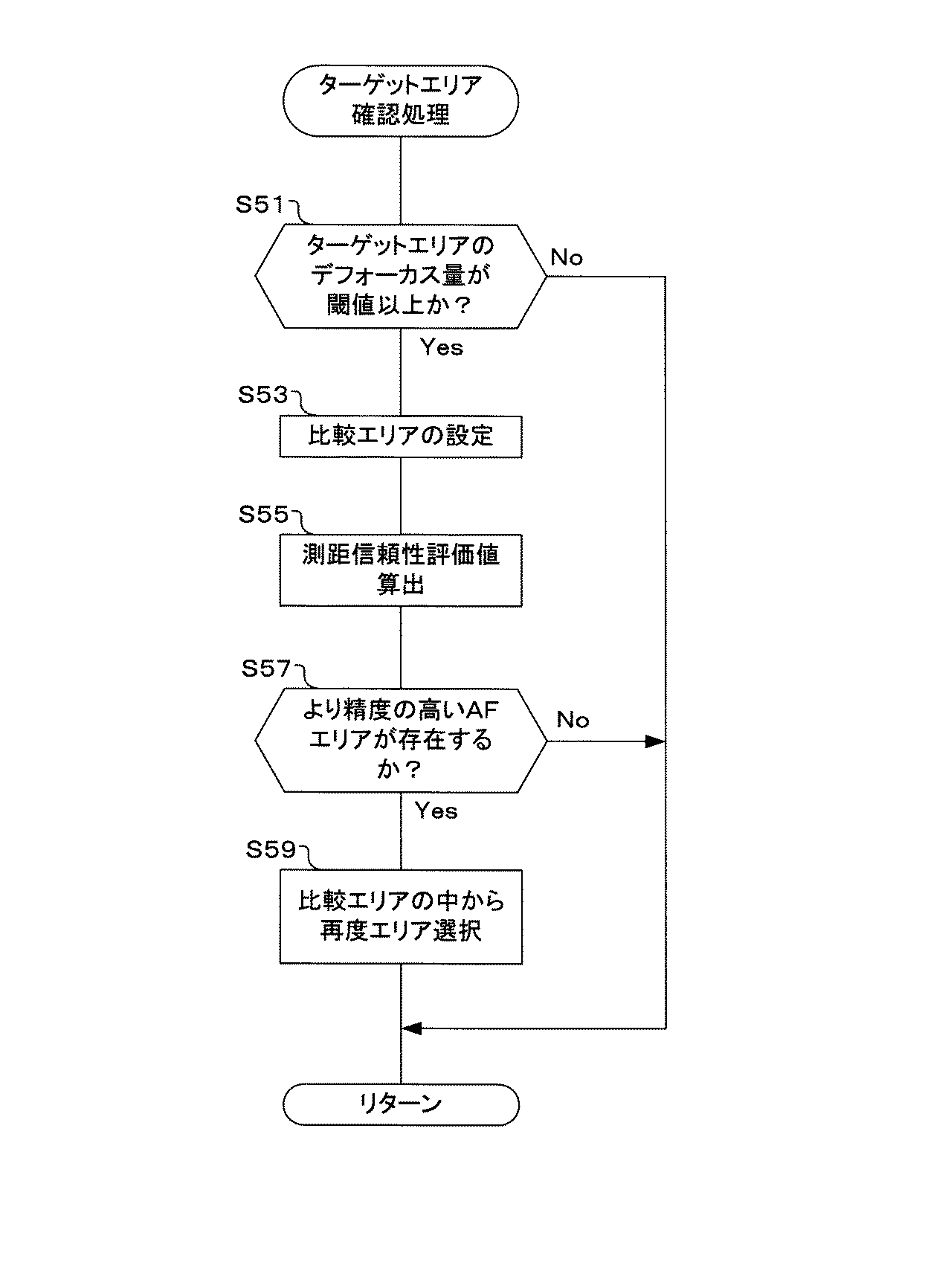
次に、図7に示すフローチャートを用いて、ステップS45におけるターゲットエリア確認処理を説明する。 Next, the target area confirmation process in step S45 will be described using the flowchart shown in FIG.
ターゲットエリア確認処理のフローに入ると、まず、ターゲットエリアのデフォーカス量が閾値以上か否かを判定する(S51)。この閾値は、想定する速度の被写体の移動範囲に相当する値に設定されており、デフォーカス量がこの閾値以上を示す場合は、異常な高速で移動する被写体に相当するので誤測距とみなすことができる。ここでは、ステップS43において決定されたターゲットエリアで算出されたデフォーカス量の絶対値と閾値を比較し、判定する。この判定の結果、デフォーカス量が閾値以上でない場合には、前回から想定すると距離範囲内に被写体があり、信頼性が高いと判断されることから、ステップ43で決定されたターゲットエリアを変更することなく使用し、ターゲットエリア確認処理のフローを終了する。
If the target area confirmation processing flow is entered, it is first determined whether or not the defocus amount of the target area is greater than or equal to a threshold value (S51). This threshold value is set to a value corresponding to the moving range of the subject at the assumed speed. If the defocus amount is greater than or equal to this threshold value, it is regarded as an erroneous distance measurement because it corresponds to a subject moving at an abnormally high speed. be able to. Here, the absolute value of the defocus amount calculated in the target area determined in step S43 is compared with the threshold value to determine. As a result of this determination, if the defocus amount is not greater than or equal to the threshold value, it is determined that there is a subject within the distance range and the reliability is high, assuming the previous time, so the target area determined in
ステップS51における判定の結果、ターゲットエリアのデフォーカス量が閾値以上ある場合には、ステップS53〜S59において、より精度の高いAFエリアがあれば、そのAFエリアに変更する。但し、複数のAFエリアが選択可能である場合に行う。 If the result of determination in step S51 is that the defocus amount of the target area is greater than or equal to the threshold value, if there is a more accurate AF area in steps S53 to S59, it is changed to that AF area. However, this is performed when a plurality of AF areas can be selected.
まず、比較エリアの設定を行う(S53)。ここでは、ステップS27(Yes)−35において決定された選択可能なAFエリアのうちでターゲットエリアとして採用されなかったAFエリアを比較エリアとして設定する。 First, a comparison area is set (S53). Here, among the selectable AF areas determined in step S27 (Yes) -35, an AF area that is not adopted as a target area is set as a comparison area.
ステップS53において比較エリアを設定すると、次に、測距信頼性評価値算出を行う(S55)。ここでは、AFターゲットエリアと、比較エリアとして設定された各AFエリアにおいて、測距信頼性評価値AFrを算出する。 Once the comparison area is set in step S53, next, a ranging reliability evaluation value is calculated (S55). Here, the ranging reliability evaluation value AFr is calculated in the AF target area and each AF area set as the comparison area.
ステップS55において測距信頼性評価値を算出すると、次に、より信頼性の高い、即ち、より精度の高いAFエリアが存在するか否かを判定する(S57)。ここでは、AFターゲットエリアと比較エリアの測距信頼性評価値AFrを比較し、AFターゲットエリアにおける測距信頼性評価値AFrよりも高い測距信頼性評価値AFrを有するAFエリアが有るか否かを判定する。 If the ranging reliability evaluation value is calculated in step S55, it is next determined whether or not there is an AF area with higher reliability, that is, higher accuracy (S57). Here, the distance measurement reliability evaluation value AFr between the AF target area and the comparison area is compared, and whether or not there is an AF area having a distance measurement reliability evaluation value AFr higher than the distance measurement reliability evaluation value AFr in the AF target area. Determine whether.
ステップS57における判定の結果、より信頼性の高い、即ち、より精度の高いAFエリアが存在する場合には、比較エリアの中から再度エリア選択を行う(S59)。ここでは、ステップS57における判定の際に、信頼性の高かった、即ち、精度の高かったAFエリアをAFターゲットエリアとして選択する。AFエリアを再選択すると、元のフローに戻る。一方、ステップS57における判定の結果、より精度の高いAFエリアが存在しない場合には、AFターゲットエリアを再選択することなく、元のフローに戻る。 If the result of determination in step S57 is that there is an AF area with higher reliability, that is, higher accuracy, area selection is performed again from the comparison areas (S59). Here, the AF area having high reliability, that is, high accuracy is selected as the AF target area in the determination in step S57. When the AF area is selected again, the original flow is restored. On the other hand, if the result of determination in step S57 is that there is no more accurate AF area, the flow returns to the original flow without reselecting the AF target area.
このように、ターゲットエリア確認処理のフローにおいては、ターゲットエリアのデフォーカス量が閾値以上の場合には(S51Yes)、AFターゲットエリアの測距信頼性評価値AFrと他の信頼性のあるAFエリアの測距信頼性評価値AFrを比較し、AFターゲットエリアの測距信頼性評価値AFrが最大の場合にはそのまま変更することなくAFターゲットエリアを用い、一方、信頼性のあるAFエリアの中のAFエリアに最大値がある場合には、たとえばそのAFエリアに置換する(S53〜S59)。このため、測距信頼性がより高いAFエリアの測距結果を使用することができ、測距ばらつきを抑制することができる。 As described above, in the flow of the target area confirmation process, when the defocus amount of the target area is equal to or larger than the threshold (Yes in S51), the AF target area ranging reliability evaluation value AFr and other reliable AF areas The distance measurement reliability evaluation value AFr of the AF target area is compared, and when the distance measurement reliability evaluation value AFr of the AF target area is the maximum, the AF target area is used as it is without being changed. If there is a maximum value in the AF area, the AF area is replaced, for example (S53 to S59). For this reason, it is possible to use a distance measurement result of an AF area with higher distance measurement reliability, and to suppress distance measurement variations.
以上説明したように、本発明の一実施形態におけるカメラは、撮影光学系(フォーカスレンズ11等)からの光束を瞳分割して光電変換することにより、焦点検出信号を生成する撮像素子33を有しており、複数のAFエリア58がそれぞれ複数のAFサブエリアに分割されており(図3参照)、複数のAFエリアを用いてオートフォーカスを行っている。そして、複数のAFサブエリアのそれぞれに対応する焦点検出信号に基づいて相関演算を行い、信頼度を出力する演算ステップと(図5のS5、図6のS25)、複数のAFサブエリアに対応する相関演算の信頼度を算出し、信頼度がより高いAFサブエリアの数が多いAFエリアを選択するAFエリア選択ステップと(図6のS21、S25、S27)、選択されたAFエリアの焦点検出信号に基づく相関演算により算出される測距データを用いて焦点調節を行うフォーカス制御ステップ(図6のS33、S43、図5のS15)を有している。このため、測距ばらつきを抑制し、動きのある被写体をコンティニュアスAFで精度よく撮影することができる。
As described above, the camera according to the embodiment of the present invention has the
なお、本発明の一実施形態においては、撮像素子に位相差検出画素を配置し、位相差法による焦点検出を行っている。しかし、これに限らず、位相差検出用の専用のセンサを設けるようにしても勿論かまわない。 In one embodiment of the present invention, a phase difference detection pixel is arranged in the image sensor, and focus detection is performed by the phase difference method. However, the present invention is not limited to this, and it is of course possible to provide a dedicated sensor for detecting the phase difference.
また、本発明の一実施形態においては、C−AFモードに設定された場合、動体予測によって焦点検出を行っていたが、動体予測を行わずに、単純に位相差法による焦点検出結果に応じて、焦点調節を行うようにしてもよい。 Further, in one embodiment of the present invention, when the C-AF mode is set, focus detection is performed by moving object prediction. However, according to a focus detection result by a phase difference method without performing moving object prediction. Thus, focus adjustment may be performed.
また、本発明の各実施形態においては、AE処理部47、AF処理部49、表示制御部55、画像処理部61、圧縮伸張部63を、本体側CPU50とは別体の構成としたが、各部の全部または一部をソフトウエアで構成し、本体側CPU50によって実行するようにしても勿論かまわない。
In each embodiment of the present invention, the
また、本実施形態においては、撮影のための機器として、デジタルカメラを用いて説明したが、カメラとしては、デジタル一眼レフカメラでもコンパクトデジタルカメラでもよく、ビデオカメラ、ムービーカメラのような動画用のカメラでもよく、さらに、携帯電話、スマートフォン、携帯情報端末(PDA:Personal Digital Assist)、パーソナルコンピュータ(PC)、タブレット型コンピュータ、ゲーム機器等に内蔵されるカメラでも構わない。いずれにしても、位相差法によって焦点検出を行う機器であれば、本発明を適用することができる。 In the present embodiment, the digital camera is used as the photographing device. However, the camera may be a digital single-lens reflex camera or a compact digital camera, and may be used for moving images such as video cameras and movie cameras. It may be a camera, and may be a camera built in a mobile phone, a smart phone, a personal digital assistant (PDA), a personal computer (PC), a tablet computer, a game machine, or the like. In any case, the present invention can be applied to any device that performs focus detection by the phase difference method.
また、本明細書において説明した技術のうち、主にフローチャートで説明した制御に関しては、プログラムで設定可能であることが多く、記録媒体や記録部に収められる場合もある。この記録媒体、記録部への記録の仕方は、製品出荷時に記録してもよく、配布された記録媒体を利用してもよく、インターネットを介してダウンロードしたものでもよい。 Of the techniques described in this specification, the control mainly described in the flowchart is often settable by a program and may be stored in a recording medium or a recording unit. The recording method for the recording medium and the recording unit may be recorded at the time of product shipment, may be a distributed recording medium, or may be downloaded via the Internet.
また、特許請求の範囲、明細書、および図面中の動作フローに関して、便宜上「まず」、「次に」等の順番を表現する言葉を用いて説明したとしても、特に説明していない箇所では、この順で実施することが必須であることを意味するものではない。 In addition, regarding the operation flow in the claims, the specification, and the drawings, even if it is described using words expressing the order such as “first”, “next”, etc. It does not mean that it is essential to implement in this order.
本発明は、上記実施形態にそのまま限定されるものではなく、実施段階ではその要旨を逸脱しない範囲で構成要素を変形して具体化できる。また、上記実施形態に開示されている複数の構成要素の適宜な組み合わせにより、種々の発明を形成できる。例えば、実施形態に示される全構成要素の幾つかの構成要素を削除してもよい。さらに、異なる実施形態にわたる構成要素を適宜組み合わせてもよい。 The present invention is not limited to the above-described embodiments as they are, and can be embodied by modifying the constituent elements without departing from the scope of the invention in the implementation stage. In addition, various inventions can be formed by appropriately combining a plurality of components disclosed in the embodiment. For example, you may delete some components of all the components shown by embodiment. Furthermore, constituent elements over different embodiments may be appropriately combined.
10・・・撮影レンズ、11・・・フォーカスレンズ、13・・・ズームレンズ、15・・・絞り、17・・・フォーカスレンズ駆動部、19・・・ズームレンズ駆動部、20・・・レンズ側システムコントローラ(レンズ側CPU)、21・・・絞り駆動部、23・・・レンズ側通信制御部、25・・・通信路、30・・・カメラ本体、31・・・メカシャッタ、33・・・撮像素子、34a〜34g・・・位相差検出画素、35・・・CDS、37・・・AMP、39・・・A/D変換器、41・・・メカシャッタ、43・・・撮像素子駆動部、45・・・メモリ、47・・・AE処理部、49・・・AF処理部、50・・・本体側システムコントローラ(本体側CPU)、51・・・本体側レンズ制御部、53・・・UI制御部、55・・・表示制御部、57・・・LCD、58・・・AFエリア、59・・・EVF、60a〜60p・・・部分、61・・・画像処理部、63・・・圧縮伸張部、65・・・記録媒体制御部、67・・・記録媒体
DESCRIPTION OF
Claims (4)
上記複数のAFエリアはそれぞれAFエリア内を分割した複数のサブエリアを有し、
上記複数のサブエリアのそれぞれに対応する焦点検出信号に基づいて相関演算を行うとともに、上記複数のサブエリアのそれぞれについて算出された上記相関演算の結果の信頼度を出力する演算部と、
上記複数のサブエリアに対応して算出された上記信頼度がより高いサブエリアの数が多いAFエリアを選択するAFエリア選択部と、
上記選択されたAFエリアの焦点検出信号に基づく相関演算により算出される測距データを用いて動体予測演算を行う動体予測演算部と、
上記動体予測演算の結果に基づいて焦点調節を行うフォーカス制御部と、
を備えたことを特徴とする撮像装置。 An imaging device having an imaging element in which a phase difference detection pixel for generating a focus detection signal is formed by photoelectrically converting a light beam from an imaging optical system by performing pupil division and performing autofocus using a plurality of AF areas In
Each of the plurality of AF areas has a plurality of sub-areas obtained by dividing the AF area.
Said plurality of rows correlation calculation based on the focus detection signal corresponding to each sub-area Utotomoni, an arithmetic unit for outputting a result of the reliability of the correlation calculation which is calculated for each of the plurality of sub-areas,
An AF area selection unit that selects an AF area having a large number of subareas with higher reliability calculated for the plurality of subareas;
A moving object prediction calculation unit that performs moving object prediction calculation using distance measurement data calculated by correlation calculation based on the focus detection signal of the selected AF area;
A focus control unit that performs focus adjustment based on the result of the moving object prediction calculation;
An imaging apparatus comprising:
上記複数のサブエリアのそれぞれに対応する焦点検出信号に基づいて相関演算を行うとともに、上記複数のサブエリアのそれぞれについて算出された上記相関演算の結果の信頼度を出力する演算ステップと、
上記複数のサブエリアに対応して算出された上記信頼度がより高いサブエリアの数が多いAFエリアを選択するAFエリア選択ステップと、
上記選択されたAFエリアの焦点検出信号に基づく相関演算により算出される測距データを用いて焦点調節を行うフォーカス制御ステップと、
を有していることを特徴とする撮像装置の制御方法。 An image sensor that generates a focus detection signal by photoelectrically converting the light beam from the imaging optical system by dividing the pupil, and a plurality of AF areas are divided into a plurality of sub-areas, respectively. In the control method in the imaging apparatus that performs autofocus using
Said plurality of rows correlation calculation based on the focus detection signal corresponding to each sub-area Utotomoni, a calculating step of outputting the result of the reliability of the correlation calculation which is calculated for each of the plurality of sub-areas,
An AF area selection step for selecting an AF area having a larger number of sub-areas with higher reliability calculated for the plurality of sub-areas;
A focus control step for performing focus adjustment using distance measurement data calculated by correlation calculation based on the focus detection signal of the selected AF area;
A control method for an imaging apparatus, comprising:
Priority Applications (3)
| Application Number | Priority Date | Filing Date | Title |
|---|---|---|---|
| JP2014209957A JP6457776B2 (en) | 2014-10-14 | 2014-10-14 | IMAGING DEVICE AND IMAGING DEVICE CONTROL METHOD |
| US14/879,144 US9344621B2 (en) | 2014-10-14 | 2015-10-09 | Imaging device and control method for imaging device |
| CN201510671524.8A CN105516582B (en) | 2014-10-14 | 2015-10-13 | The control method of photographic device and photographic device |
Applications Claiming Priority (1)
| Application Number | Priority Date | Filing Date | Title |
|---|---|---|---|
| JP2014209957A JP6457776B2 (en) | 2014-10-14 | 2014-10-14 | IMAGING DEVICE AND IMAGING DEVICE CONTROL METHOD |
Publications (2)
| Publication Number | Publication Date |
|---|---|
| JP2016080791A JP2016080791A (en) | 2016-05-16 |
| JP6457776B2 true JP6457776B2 (en) | 2019-01-23 |
Family
ID=55656332
Family Applications (1)
| Application Number | Title | Priority Date | Filing Date |
|---|---|---|---|
| JP2014209957A Active JP6457776B2 (en) | 2014-10-14 | 2014-10-14 | IMAGING DEVICE AND IMAGING DEVICE CONTROL METHOD |
Country Status (3)
| Country | Link |
|---|---|
| US (1) | US9344621B2 (en) |
| JP (1) | JP6457776B2 (en) |
| CN (1) | CN105516582B (en) |
Families Citing this family (15)
| Publication number | Priority date | Publication date | Assignee | Title |
|---|---|---|---|---|
| KR102346622B1 (en) * | 2014-08-04 | 2022-01-04 | 엘지이노텍 주식회사 | Image sensor and image pick-up apparatus including the same |
| US10523860B2 (en) * | 2016-05-12 | 2019-12-31 | Canon Kabushiki Kaisha | Focus detection device, control method thereof, and image capture apparatus |
| JP6981410B2 (en) * | 2016-06-28 | 2021-12-15 | ソニーグループ株式会社 | Solid-state image sensor, electronic equipment, lens control method and vehicle |
| JP6742173B2 (en) * | 2016-06-30 | 2020-08-19 | キヤノン株式会社 | Focus adjusting device and method, and imaging device |
| JP6462189B2 (en) * | 2016-07-06 | 2019-01-30 | 富士フイルム株式会社 | Focus control device, focus control method, focus control program, lens device, imaging device |
| CN106060407A (en) * | 2016-07-29 | 2016-10-26 | 努比亚技术有限公司 | Focusing method and terminal |
| US10326925B2 (en) * | 2016-08-10 | 2019-06-18 | Canon Kabushiki Kaisha | Control apparatus for performing focus detection, image capturing apparatus, control method, and non-transitory computer-readable storage medium |
| JP2018101055A (en) | 2016-12-20 | 2018-06-28 | オリンパス株式会社 | Focus adjustment device, imaging device and focus adjustment method |
| CN108337424B (en) * | 2017-01-17 | 2021-04-16 | 中兴通讯股份有限公司 | Phase focusing method and device thereof |
| US10609274B2 (en) | 2018-03-30 | 2020-03-31 | Qualcomm Incorporated | Systems and methods for autofocus and depth map generation |
| US10582111B2 (en) | 2018-03-30 | 2020-03-03 | Qualcomm Incorporated | Systems and methods for autofocus and depth map generation |
| JP2020148980A (en) | 2019-03-15 | 2020-09-17 | オリンパス株式会社 | Imaging device and focus adjustment method |
| JP6914988B2 (en) * | 2019-04-26 | 2021-08-04 | キヤノン株式会社 | Imaging device and its control method |
| JP7289055B2 (en) * | 2019-06-27 | 2023-06-09 | パナソニックIpマネジメント株式会社 | Imaging device |
| JP7379083B2 (en) * | 2019-10-24 | 2023-11-14 | キヤノン株式会社 | Control device, imaging device, control method, and program |
Family Cites Families (21)
| Publication number | Priority date | Publication date | Assignee | Title |
|---|---|---|---|---|
| JP2753544B2 (en) | 1991-06-07 | 1998-05-20 | 株式会社ニコン | Focus detection device |
| US5900927A (en) | 1993-10-13 | 1999-05-04 | Fuji Photo Film Co., Ltd. | Variable target autofocusing and range finder for measuring distance to a subject |
| JPH08271784A (en) * | 1995-03-30 | 1996-10-18 | Canon Inc | Optical instrument with function of detecting line of sight |
| US5937216A (en) * | 1996-05-24 | 1999-08-10 | Nikon Corporation | Focal adjustment apparatus for a camera |
| US6115553A (en) * | 1996-09-17 | 2000-09-05 | Asahi Kogaku Kogyo Kabushiki Kaisha | Multipoint autofocus system |
| JP4398020B2 (en) * | 1999-11-02 | 2010-01-13 | オリンパス株式会社 | Multi-point autofocus camera |
| JP2002072283A (en) * | 2000-08-23 | 2002-03-12 | Minolta Co Ltd | Camera |
| JP4109066B2 (en) * | 2002-09-27 | 2008-06-25 | フジノン株式会社 | Ranging device and camera equipped with the same |
| JP4874669B2 (en) * | 2006-02-22 | 2012-02-15 | Hoya株式会社 | Autofocus unit and digital camera |
| JP2008134413A (en) | 2006-11-28 | 2008-06-12 | Sony Corp | Imaging apparatus |
| JP5003132B2 (en) | 2006-12-07 | 2012-08-15 | ソニー株式会社 | Imaging device and imaging apparatus |
| JP2010020015A (en) * | 2008-07-09 | 2010-01-28 | Canon Inc | Image pick up apparatus |
| JP5597078B2 (en) * | 2010-09-17 | 2014-10-01 | キヤノン株式会社 | Imaging apparatus and control method thereof |
| CN103238098B (en) * | 2010-11-30 | 2015-04-15 | 富士胶片株式会社 | Imaging device and focal position detection method |
| CN103430073B (en) * | 2011-03-31 | 2014-12-31 | 富士胶片株式会社 | Imaging device, and method for controlling imaging device |
| KR101773168B1 (en) * | 2011-07-21 | 2017-09-12 | 삼성전자주식회사 | Apparatus and method for controlling focus by image sensor for outputting phase difference signal |
| JP5325966B2 (en) * | 2011-11-25 | 2013-10-23 | オリンパス株式会社 | Imaging apparatus and imaging method |
| KR102053316B1 (en) * | 2012-08-01 | 2020-01-08 | 삼성전자주식회사 | Digital photographing apparatus |
| JP6204660B2 (en) * | 2012-12-21 | 2017-09-27 | キヤノン株式会社 | Imaging apparatus and control method thereof |
| JP6045362B2 (en) * | 2013-01-17 | 2016-12-14 | オリンパス株式会社 | Imaging apparatus and focus detection method |
| JP2015041988A (en) * | 2013-08-23 | 2015-03-02 | キヤノン株式会社 | Imaging apparatus, control method and program of imaging apparatus |
-
2014
- 2014-10-14 JP JP2014209957A patent/JP6457776B2/en active Active
-
2015
- 2015-10-09 US US14/879,144 patent/US9344621B2/en active Active
- 2015-10-13 CN CN201510671524.8A patent/CN105516582B/en active Active
Also Published As
| Publication number | Publication date |
|---|---|
| CN105516582B (en) | 2018-10-12 |
| US9344621B2 (en) | 2016-05-17 |
| US20160105600A1 (en) | 2016-04-14 |
| CN105516582A (en) | 2016-04-20 |
| JP2016080791A (en) | 2016-05-16 |
Similar Documents
| Publication | Publication Date | Title |
|---|---|---|
| JP6457776B2 (en) | IMAGING DEVICE AND IMAGING DEVICE CONTROL METHOD | |
| JP5523143B2 (en) | Imaging apparatus and automatic focusing method | |
| JP6474693B2 (en) | Focus detection apparatus, focus detection method, and recording medium | |
| JP6137840B2 (en) | Camera system | |
| US10175451B2 (en) | Imaging apparatus and focus adjustment method | |
| US10412292B2 (en) | Lens control device, lens control method, and recording medium | |
| JP6634298B2 (en) | Imaging device and imaging method | |
| US10477101B2 (en) | Focus detection apparatus, control method and storage medium | |
| JP2011217103A (en) | Compound eye photographing method and apparatus | |
| JP7281977B2 (en) | Focus adjustment device and focus adjustment method | |
| JP5403111B2 (en) | Image tracking device | |
| JP5056136B2 (en) | Image tracking device | |
| JP4565549B2 (en) | Imaging apparatus and focus control method thereof | |
| JP2017194558A (en) | Imaging device and imaging method | |
| JP2007225897A (en) | Focusing position determination device and method | |
| JP2018011268A (en) | Imaging apparatus, image superimposition method, and program | |
| CN106993110B (en) | Image pickup apparatus and control method thereof | |
| JP2020118764A (en) | Focus controller and focus control method | |
| JP5635546B2 (en) | Imaging device and method for controlling imaging device | |
| JP7129864B2 (en) | Imaging device and its control method | |
| JP6294607B2 (en) | IMAGING DEVICE, ITS CONTROL METHOD, PROGRAM, AND STORAGE MEDIUM | |
| JP6997544B2 (en) | Imaging device and its control method, program, storage medium | |
| JP2018098764A (en) | Imaging apparatus and image synthesis method | |
| JP5069076B2 (en) | Imaging apparatus and continuous imaging method | |
| WO2015182021A1 (en) | Image pickup control apparatus, image pickup apparatus, and image pickup control method |
Legal Events
| Date | Code | Title | Description |
|---|---|---|---|
| A621 | Written request for application examination |
Free format text: JAPANESE INTERMEDIATE CODE: A621 Effective date: 20171005 |
|
| A977 | Report on retrieval |
Free format text: JAPANESE INTERMEDIATE CODE: A971007 Effective date: 20180412 |
|
| A131 | Notification of reasons for refusal |
Free format text: JAPANESE INTERMEDIATE CODE: A131 Effective date: 20180423 |
|
| A521 | Request for written amendment filed |
Free format text: JAPANESE INTERMEDIATE CODE: A523 Effective date: 20180618 |
|
| TRDD | Decision of grant or rejection written | ||
| A01 | Written decision to grant a patent or to grant a registration (utility model) |
Free format text: JAPANESE INTERMEDIATE CODE: A01 Effective date: 20181130 |
|
| A61 | First payment of annual fees (during grant procedure) |
Free format text: JAPANESE INTERMEDIATE CODE: A61 Effective date: 20181221 |
|
| R151 | Written notification of patent or utility model registration |
Ref document number: 6457776 Country of ref document: JP Free format text: JAPANESE INTERMEDIATE CODE: R151 |
|
| S111 | Request for change of ownership or part of ownership |
Free format text: JAPANESE INTERMEDIATE CODE: R313113 |
|
| R350 | Written notification of registration of transfer |
Free format text: JAPANESE INTERMEDIATE CODE: R350 |
|
| R250 | Receipt of annual fees |
Free format text: JAPANESE INTERMEDIATE CODE: R250 |
|
| R250 | Receipt of annual fees |
Free format text: JAPANESE INTERMEDIATE CODE: R250 |
|
| R250 | Receipt of annual fees |
Free format text: JAPANESE INTERMEDIATE CODE: R250 |