JP6452531B2 - connector - Google Patents
connector Download PDFInfo
- Publication number
- JP6452531B2 JP6452531B2 JP2015083615A JP2015083615A JP6452531B2 JP 6452531 B2 JP6452531 B2 JP 6452531B2 JP 2015083615 A JP2015083615 A JP 2015083615A JP 2015083615 A JP2015083615 A JP 2015083615A JP 6452531 B2 JP6452531 B2 JP 6452531B2
- Authority
- JP
- Japan
- Prior art keywords
- contact
- connector
- contacts
- mating
- long wall
- Prior art date
- Legal status (The legal status is an assumption and is not a legal conclusion. Google has not performed a legal analysis and makes no representation as to the accuracy of the status listed.)
- Active
Links
- 230000013011 mating Effects 0.000 claims description 42
- 230000005489 elastic deformation Effects 0.000 description 2
- 230000004048 modification Effects 0.000 description 1
- 238000012986 modification Methods 0.000 description 1
- 238000005549 size reduction Methods 0.000 description 1
Images


Classifications
-
- H—ELECTRICITY
- H01—ELECTRIC ELEMENTS
- H01R—ELECTRICALLY-CONDUCTIVE CONNECTIONS; STRUCTURAL ASSOCIATIONS OF A PLURALITY OF MUTUALLY-INSULATED ELECTRICAL CONNECTING ELEMENTS; COUPLING DEVICES; CURRENT COLLECTORS
- H01R24/00—Two-part coupling devices, or either of their cooperating parts, characterised by their overall structure
- H01R24/84—Hermaphroditic coupling devices
-
- H—ELECTRICITY
- H01—ELECTRIC ELEMENTS
- H01R—ELECTRICALLY-CONDUCTIVE CONNECTIONS; STRUCTURAL ASSOCIATIONS OF A PLURALITY OF MUTUALLY-INSULATED ELECTRICAL CONNECTING ELEMENTS; COUPLING DEVICES; CURRENT COLLECTORS
- H01R12/00—Structural associations of a plurality of mutually-insulated electrical connecting elements, specially adapted for printed circuits, e.g. printed circuit boards [PCB], flat or ribbon cables, or like generally planar structures, e.g. terminal strips, terminal blocks; Coupling devices specially adapted for printed circuits, flat or ribbon cables, or like generally planar structures; Terminals specially adapted for contact with, or insertion into, printed circuits, flat or ribbon cables, or like generally planar structures
- H01R12/70—Coupling devices
- H01R12/71—Coupling devices for rigid printing circuits or like structures
- H01R12/712—Coupling devices for rigid printing circuits or like structures co-operating with the surface of the printed circuit or with a coupling device exclusively provided on the surface of the printed circuit
- H01R12/716—Coupling device provided on the PCB
Landscapes
- Coupling Device And Connection With Printed Circuit (AREA)
- Connector Housings Or Holding Contact Members (AREA)
Description
本発明は、少なくとも2種類のコンタクトを備えるコネクタに関する。 The present invention relates to a connector having at least two types of contacts.
この種のコネクタとしては、例えば、特許文献1に開示されたものがある。図26に示されるように、特許文献1のコネクタ900は、第1コンタクト910と、第2コンタクト920と、グランドコンタクト930と、それらを保持するハウジング940とを備えている。ハウジング940は、板状の支持部942と、長壁部944間に形成されたスロット946とを有している。第1コンタクト910は、支持部942に部分的に支持されており、第2コンタクト920は、スロット946に部分的に収容されている。即ち、第2コンタクト920は、長壁部944間に部分的に位置している。コネクタ900は、同一構造の相手側コネクタ950と嵌合するものである。即ち、コネクタ900と相手側コネクタ950とは雌雄同体である。コネクタ900が相手側コネクタ950と嵌合する際、コネクタ900の第1コンタクト910は相手側コネクタ950の第2コンタクト920に挿入され、コネクタ900の第2コンタクト920は相手側コネクタ950の第1コンタクト910を受容する。その際、コネクタ900のグランドコンタクト930は、相手側コネクタ950のグランドコンタクト930に接続される。かかる構造のため、コネクタ900と相手側コネクタ950との嵌合は、こじりに対して耐性がある。
An example of this type of connector is disclosed in
本発明は、こじりに対して耐性がある構造を有すると共に小型化されたコネクタを提供することを目的とする。 An object of the present invention is to provide a connector that has a structure resistant to twisting and is miniaturized.
本発明は、第1のコネクタとして、
複数の相手側第1コンタクトと複数の相手側第2コンタクトとを備える相手側コネクタと第1方向に沿って嵌合可能なコネクタであって、
前記コネクタは、複数の第1コンタクトと、複数の第2コンタクトと、前記第1コンタクト及び前記第2コンタクトを保持するハウジングとを備えており、
前記第1コンタクトは、前記コネクタが前記相手側コネクタに嵌合した際に、前記相手側第1コンタクトに接触する第1接触部を夫々有しており、
前記第2コンタクトは、前記コネクタが前記相手側コネクタに嵌合した際に、前記相手側第2コンタクトに接触する第2接触部を夫々有しており、
前記ハウジングは、少なくとも2つの長壁部と、少なくとも1つの支持部とを有しており、
前記長壁部は、前記第1方向と直交する第2方向に延びており、
前記長壁部は、前記第1方向及び前記第2方向の双方と直交する第3方向において離間配置され、それによって、前記長壁部の間にはスロットが形成されており、
前記支持部は、前記長壁部の1つから前記第1方向に沿って突出していると共に前記第2方向に延びる板状の形状を有しており、
前記第1接触部は、前記支持部に支持されており、
前記第2接触部は、少なくとも部分的に前記スロット内に位置している
コネクタを提供する。
The present invention provides the first connector as
A mating connector comprising a plurality of mating first contacts and a plurality of mating second contacts and a connector that can be fitted along the first direction,
The connector includes a plurality of first contacts, a plurality of second contacts, and a housing that holds the first contacts and the second contacts,
Each of the first contacts has a first contact portion that comes into contact with the mating first contact when the connector is fitted to the mating connector,
Each of the second contacts has a second contact portion that comes into contact with the mating second contact when the connector is fitted to the mating connector.
The housing has at least two long wall portions and at least one support portion;
The long wall portion extends in a second direction orthogonal to the first direction,
The long wall portions are spaced apart in a third direction orthogonal to both the first direction and the second direction, whereby a slot is formed between the long wall portions,
The support portion has a plate-like shape protruding from the one of the long wall portions along the first direction and extending in the second direction,
The first contact portion is supported by the support portion,
The second contact provides a connector located at least partially within the slot.
また、本発明は、第2のコネクタとして、第1のコネクタであって、
前記ハウジングは、3つ以上の前記長壁部と、2つ以上の前記支持部とを有しており、
前記ハウジングには、2つ以上の前記スロットが形成されている
前記第1コンタクトは、2以上の第1コンタクト列を構成しており、
前記第1コンタクト列は、前記支持部に夫々対応しており、
前記第2コンタクトは、2以上の第2コンタクト列を構成しており、
前記第2コンタクト列は、前記スロットに夫々対応している
コネクタを提供する。
Moreover, this invention is a 1st connector as a 2nd connector,
The housing has three or more long wall portions and two or more support portions,
In the housing, two or more slots are formed. The first contact constitutes two or more first contact rows,
The first contact rows correspond to the support portions, respectively.
The second contact constitutes two or more second contact rows,
The second contact row provides a connector corresponding to each of the slots.
また、本発明は、第3のコネクタとして、第1又は第2のコネクタであって、
前記第1接触部は、前記第3方向において互いに離れて位置する2つの接点を有している
コネクタを提供する。
Moreover, this invention is a 1st or 2nd connector as a 3rd connector,
The first contact portion provides a connector having two contact points located apart from each other in the third direction.
また、本発明は、第4のコネクタとして、第3のコネクタであって、
前記第1接触部は、U字状の形状を有している
コネクタを提供する。
Moreover, this invention is a 3rd connector as a 4th connector,
The first contact portion provides a connector having a U-shape.
また、本発明は、第5のコネクタとして、第4のコネクタであって、
前記ハウジングには、前記スロットと通じていると共に前記第2コンタクトを部分的に収容するコンタクト収容部が形成されており、
前記第1方向に沿って見た場合に、前記第1接触部の位置と前記コンタクト収容部の位置とは部分的に重なっている
コネクタを提供する。
Moreover, this invention is a 4th connector as a 5th connector,
The housing is formed with a contact accommodating portion that communicates with the slot and partially accommodates the second contact,
A connector is provided in which the position of the first contact portion and the position of the contact accommodating portion partially overlap when viewed along the first direction.
また、本発明は、第6のコネクタとして、第4又は第5のコネクタであって、
前記コネクタは、使用時に対象物に搭載されるものであり、
前記第1コンタクトは、前記対象物に固定される第1固定部と、前記第1接触部と前記第1固定部とを連結する第1連結部とを有しており、
前記第1連結部と前記第1固定部とは直線状に並んでいる
コネクタを提供する。
Moreover, this invention is a 4th or 5th connector as a 6th connector,
The connector is mounted on an object at the time of use,
The first contact includes a first fixing portion that is fixed to the object, and a first connecting portion that connects the first contact portion and the first fixing portion,
The first connecting part and the first fixing part provide a connector arranged in a straight line.
また、本発明は、第7のコネクタとして、第4又は第5のコネクタであって、
前記コネクタは、使用時に対象物に搭載されるものであり、
前記第1コンタクトは、前記対象物に固定される第1固定部と、前記第1接触部と前記第1固定部とを連結する第1連結部とを有しており、
前記第3方向において、前記第1固定部は、前記第1接触部の前記2つの接点の間に位置している
コネクタを提供する。
Moreover, this invention is a 4th or 5th connector as a 7th connector,
The connector is mounted on an object at the time of use,
The first contact includes a first fixing portion that is fixed to the object, and a first connecting portion that connects the first contact portion and the first fixing portion,
In the third direction, the first fixing portion provides a connector positioned between the two contact points of the first contact portion.
また、本発明は、第8のコネクタとして、第6又は第7のコネクタであって、
前記第3方向において、前記第1の固定部は、前記長壁部の1つの中央に位置している
コネクタを提供する。
Moreover, this invention is a 6th or 7th connector as an 8th connector,
In the third direction, the first fixing portion provides a connector located at the center of one of the long wall portions.
また、本発明は、第1のコネクタ組立体として、第1乃至第8のいずれかのコネクタと、前記相手側コネクタとを備えるコネクタ組立体を提供する。 The present invention also provides a connector assembly including any one of the first to eighth connectors and the mating connector as the first connector assembly.
また、本発明は、第2のコネクタ組立体として、第1のコネクタ組立体であって、
前記コネクタと前記相手側コネクタとは互いに同一形状を有しているコネクタ組立体を提供する。
Moreover, this invention is a 1st connector assembly as a 2nd connector assembly,
The connector and the mating connector provide a connector assembly having the same shape.
第1コンタクトを支持する支持部が第2コンタクトを収容するスロットの長壁部から嵌合方向に沿って延びている。そのため、長壁部と支持部との間のスペースを省略することができ、コネクタの小型化を図ることができる。 A support portion that supports the first contact extends along the fitting direction from the long wall portion of the slot that accommodates the second contact. Therefore, the space between the long wall portion and the support portion can be omitted, and the connector can be miniaturized.
図面を参照して本発明の実施の形態について詳細に説明する。 Embodiments of the present invention will be described in detail with reference to the drawings.
(第1の実施の形態)
図1に示されるように、本発明の第1の実施の形態によるコネクタ組立体100は、第1及び第2のコネクタ200,300を有している。第1及び第2のコネクタ200,300は、同一の構造を有する雌雄同体のコネクタである。これら第1及び第2のコネクタ200,300は、図2乃至図5から理解されるように、第1方向に沿って、互いに嵌合可能である。また、第1及び第2のコネクタ200,300は、第1方向に沿って、分離可能である。なお、本実施の形態において、第1方向はZ方向である。
(First embodiment)
As shown in FIG. 1, the
図6乃至図11を参照して後述するように、第1のコネクタ200は、複数の第1コンタクト210と複数の第2コンタクト220を有している。図5から理解されるように、第1のコネクタ200が相手側コネクタである第2のコネクタ300と嵌合した際、第1コンタクト210の一部は、相手側コネクタの相手側第1コンタクト310に収容される。また、第2コンタクト220は、相手側コネクタの相手側第2コンタクト320の一部を収容する。その結果、第1コンタクト210は、相手側第1コンタクト310に接触し、第2コンタクト220は、相手側コネクタの相手側第2コンタクト320に接触する。
As described later with reference to FIGS. 6 to 11, the
上述したように、第1及び第2のコネクタ200,300は、同一の構造を有しているので、以下の説明は、第1のコネクタ200について行う。
As described above, since the first and
図6乃至図11を参照すると、第1のコネクタ200は、複数の第1コンタクト210と、複数の第2コンタクト220と、これらの第1及び第2コンタクト210,220を保持するハウジング230とを有している。
6 to 11, the
複数の第1コンタクト210は、第2方向に沿って延びる少なくとも1つの第1コンタクト列240を形成するように配置される。複数の第1コンタクト列240が設けられる場合、複数の第1コンタクト列240は、第2方向に直交する第3方向に所定の間隔を空けて配置される。本実施の形態において、第2方向はX方向であり、第3方向はY方向である。即ち、第2方向及び第3方向は、それぞれ第1方向と直交している。本実施の形態では、複数の第1コンタクト210は、第2方向に沿って第1の間隔で配列されるとともに、第3方向に沿って第2の間隔で配列され、5つの第1コンタクト列240を形成している。
The plurality of
複数の第2コンタクト220は、第1コンタクト210と同様に配置される。即ち、複数の第2コンタクト220もまた、少なくとも1つの第2コンタクト列250を形成する。本実施の形態では、複数の第2コンタクト220は、第2方向に沿って第1の間隔で配列されるとともに、第3方向に沿って第2の間隔で配列される。
The plurality of
複数の第2コンタクト220の数は、複数の第1コンタクト210の数に等しい。また、第1コンタクト列240と第2コンタクト列250は、第3方向において交互に配置される。したがって、第3方向において、各第1コンタクト210の一方の側(−Y方向側)には、それぞれ対応する第2コンタクト220が位置する。
The number of the plurality of
ハウジング230は、図11から理解されるように、少なくとも2つの長壁部231と、少なくとも1つの支持部232と、複数のガイド部233を有している。
As understood from FIG. 11, the
各長壁部231は、第1方向へ突き出し、かつ第2方向へ延びるように形成されている。また、少なくとも2つの長壁部231は、第3方向において所定の間隔を空けて離間配置されている。図6から理解されるように、隣接する2つの長壁部231は、第2方向の両端部において、短壁部234によってそれぞれ連結される。短壁部234は、第1方向へ突き出し、かつ第3方向へ延びるよう形成されている。また、図11から理解されるように、隣接する2つの長壁部231とそれらを連結する短壁部234は、それらに囲まれたスロット235を規定する。各スロット235は、隣接する2つの長壁部231の間に位置し、第2コンタクト列250にそれぞれ対応している。
Each
また、隣接する2つの長壁部231の間には、スロット235に通じるとともに、第2コンタクト220に各々対応するコンタクト収容部236が形成されている。コンタクト収容部236は、スロット235の一部であるとも言える。コンタクト収容部236は、対応する第2コンタクト220の一部を収容する。
Further, between the two adjacent
各支持部232は、対応する長壁部231から第1方向へ突き出し、かつ第2方向へ延びるように形成される。そして、支持部232は、板状の形状を有している。また、支持部232は、第1コンタクト列240に各々対応している。
Each
複数のガイド部233は、第1のコネクタ200の外周に沿って配置されている。これらのガイド部233は、第1のコネクタ200を第2のコネクタ300に嵌合させる際、第1のコネクタ200を第2のコネクタ300に関して相対的に適切な位置へと導く。
The plurality of
図12に示されるように、第1コンタクト210の各々は、第1接触部211と、第1固定部212と、第1接触部211と第1固定部212とを連結する第1連結部213とを有している。
As shown in FIG. 12, each of the
図14に示されるように、第1接触部211は、相手側第1コンタクト310に接触する少なくとも1つの第1接点を有する。本実施の形態では、第1接触部211は、U字状の形状を有しており、第3の方向において離れて位置する2つの第1接点214,215を有する。
As shown in FIG. 14, the
図12を参照すると、第1固定部212は、第1のコネクタ200が使用時に搭載される対象物(図示せず)に固定される。
Referring to FIG. 12, the
第1連結部213は、第1接触部211と第1固定部212との間を電気的、機械的に連結する。本実施の形態において、第1連結部213は、第1接触部211と第1固定部212とを直線的に連結する。そして、第1連結部213は、第1接触部211の一部及び第1固定部212と直線状に並んでいる。
The first connecting
図13及び図14を参照すると、第2コンタクト220の各々は、相手側第2コンタクト320に接触する第2接触部221と、対象物(図示せず)に固定される第2固定部222と、第2接触部221と第2固定部222とを連結する第2連結部223とを有している。第2接触部221は、相手側第2コンタクト320の少なくとも一つの接点に対応する少なくとも一つの第2接点を有する。本実施の形態では、第2接触部221は、第3方向において離れて位置する2つの第2接点224,225を有する。
Referring to FIGS. 13 and 14, each of the
図14から理解されるように、第1接点214,215は、相手側第1コンタクト310と接触し、第2接点224,225は、相手側第2コンタクト320と接触する。
As understood from FIG. 14, the
再び、図11を参照すると、第1コンタクト210の第1接触部211は、支持部232によって支持されている。また、支持部232の表面は、第1接触部211の接触面(接点)から突出していない。換言すると、支持部232の表面は、第1接触部211の表面よりも内部側に位置している。
Referring to FIG. 11 again, the
本実施の形態では、上記のとおり、第1コンタクト210が支持部232によって支持されている。そして、図5から理解されるように、第1のコネクタ200と第2のコネクタ300とを嵌合させたとき、支持部232は相手側コネクタのスロット(235)に受容される。これにより、第1のコネクタ200と第2のコネクタ300の間にこじる力が加えられたとき、支持部232が相手側コネクタ(300)とともにその力を受け止める。その結果、コネクタ組立体100にこじる力が加わった際に、第1コンタクト210の変形を防止することができる。こうして、第1コンタクト210を含むコネクタ組立体100は、こじりに対して耐性を有する。
In the present embodiment, as described above, the
また、第1接触部211の位置は、第1の方向に沿って見た場合に、一方の側(−Y方向)に隣接する第2コンタクト220の一部を収容するコンタクト収容部236の位置と部分的に重なっている。換言すると、第1接触部211とそれに対応するコンタクト収容部236とを第3方向に延びる仮想的な軸上に投影した場合に、第1接触部211とコンタクト収容部236とは部分的に重なっている。
Further, the position of the
一方、第2コンタクト220の第2接触部221は、少なくともその一部がコンタクト収容部236に収容されている。コンタクト収容部236は、第2コンタクト220の第2接触部221の弾性変形を許容する大きさを有している。これにより、スロット235に相手側第2コンタクト320が挿入されるのに伴い、第2コンタクト220の2つの第2接点224,225(図13又は図14参照)間の距離を変化させ、相手側第2コンタクト320の進入を許容することができる。また、弾性変形による反発力により第2接点224,225を相手側第2コンタクト320に確実に接触させることができる。
On the other hand, at least a part of the
本実施の形態によれば、支持部232がスロット235を規定する長壁部231から第1方向(Z方向又は嵌合方向)に沿って延びている。つまり、第3方向において、長壁部231と支持部232との間にはスペースが存在しない。これにより、本実施の形態による第1のコネクタ200の小型化が実現できる。また、第1のコネクタ200と第1のコネクタ200と同一構造の第2のコネクタ300とを含むコネクタ組立体100の小型化を実現することができる。しかも、コネクタ組立体100は、こじりに対して耐性を有している。
According to the present embodiment, the
なお、本実施の形態による第1のコネクタ200では、第1コンタクト210の位置が長壁部231に対して第3方向において偏りを持つ。これにより、後述する第2の実施形態による第1のコネクタ1200よりもさらに小型化が可能である。
In the
(第2の実施の形態)
次に、本発明の第2の実施の形態について詳細に説明する。なお、図15乃至図25において、図2乃至図14に示される構成要素と同じ構成要素に対しては、同じ参照番号が付されている。そして、それらの説明は省略される。また、図15乃至図25において、図2乃至図14に示される構成要素に対応するけれどもその形状が異なる構成要素に対しては、図2乃至図14において使用される参照番号の前に“1”を付した参照番号を付与している。
(Second Embodiment)
Next, a second embodiment of the present invention will be described in detail. 15 to 25, the same reference numerals are given to the same components as those shown in FIGS. Those explanations are omitted. 15 to 25, the components corresponding to the components shown in FIGS. 2 to 14 but having different shapes are indicated by “1” before the reference numerals used in FIGS. Reference numbers with “” are given.
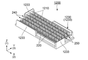
図15乃至図18から理解されるように、本実施の形態によるコネクタ組立体1100がコネクタ組立体100と大きく異なる点は、第1のコネクタ1200(及び第2のコネクタ1300)のハウジング1230の形状及び第1コンタクト1210(及び相手側第2コンタクト1320)の形状である。ハウジング1230の形状については、ガイド部1233の数とその形状、及び第3方向における支持部232と長壁部1231との相対位置関係が、ハウジング230と異なっている。その他の点については、コネクタ組立体1100は、コネクタ組立体100と同様に構成される。
As understood from FIGS. 15 to 18, the
図19乃至図23から理解されるように、ガイド部1233の数は、第1の実施の形態のガイド部233の数よりも少ない。また、少なくとも一部のガイド部1233のサイズは、第1の実施の形態のガイド部233よりも大きい。本実施の形態では、第1のコネクタ1200の長辺側に位置するガイド部1233は、第1の実施の形態のガイド部233よりも大きい。このように、本実施の形態では、ガイド部233の数を減らしたことにより、第1のコネクタ1200の構造を簡略化できる。また、少なくとも一部のガイド部1233のサイズを大きくしたことにより、ガイド部1233の数を減らしても、第1のコネクタ1200の嵌合を適切にガイドすることができる。
As can be understood from FIGS. 19 to 23, the number of
図24及び図25から理解されるように、第1コンタクト1210の各々は、第1接触部1211と、第1固定部1212と、第1接触部1211と第1固定部1212とを連結する第1連結部1213とを有している。
As understood from FIGS. 24 and 25, each of the
ここで、第1連結部1213は、オフセット部1217を含む。オフセット部1217は、第1固定部1212が第3方向(Y方向)において2つの第1接点1214,1215の間に位置するように折れ曲がっている。オフセット部1217は、2つの第1接点1214,1215の中央位置が第1固定部1212の中央位置の第1方向の真上に位置するように、折れ曲がっていてよい。この構成によれば、第3方向において、第1固定部1212を対応する長壁部1231の中央に位置させることができる。
Here, the first connecting
本実施の形態においても、第3方向(Y方向)において、各長壁部1231と支持部232との間にスペースが存在しないので、第1のコネクタ1200の小型化を実現することができる。また、第1のコネクタ1200を含むコネクタ組立体1100の小型化を実現することができる。もちろん、コネクタ組立体1100は、こじりに対して耐性を有している。
Also in this embodiment, since there is no space between each
以上、本発明の実施の形態について具体的に説明したが、本発明はこれに限定されるものではなく、様々な変形や応用が可能である。 Although the embodiment of the present invention has been specifically described above, the present invention is not limited to this, and various modifications and applications are possible.
例えば、上記実施の形態では、コネクタの外形は、第1の方向に沿ってみた場合、長方形であったが、正方形や円形等、他の形状でもあってもよい。また、上記実施の形態では、第1コネクタはU字形状を有していたが、他の形状、例えば、I字形状を有していてもよい。第2コネクタの形状は、第1コネクタの形状に応じて変形し得る。 For example, in the above embodiment, the outer shape of the connector is rectangular when viewed in the first direction, but may be other shapes such as a square or a circle. Moreover, in the said embodiment, although the 1st connector had U shape, you may have another shape, for example, I shape. The shape of the second connector can be deformed according to the shape of the first connector.
100 コネクタ組立体
200 第1のコネクタ
210 第1コンタクト
211 第1接触部
212 第1固定部
213 第1連結部
214,215 第1接点
220 第2コンタクト
221 第2接触部
222 第2固定部
223 第2連結部
224,225 第2接点
230 ハウジング
231 長壁部
232 支持部
233 ガイド部
234 短壁部
235 スロット
236 コンタクト収容部
240 第1コンタクト列
250 第2コンタクト列
300 第2のコネクタ
310 相手側第1コンタクト
320 相手側第2コンタクト
1100 コネクタ組立体
1200 第1のコネクタ
1210 第1コンタクト
1211 第1接触部
1212 第1固定部
1213 第1連結部
1214,1215 第1接点
1217 オフセット部
1230 ハウジング
1231 長壁部
1233 ガイド部
1300 第2のコネクタ
1320 相手側第2コンタクト
DESCRIPTION OF
Claims (9)
前記コネクタは、複数の第1コンタクトと、複数の第2コンタクトと、前記第1コンタクト及び前記第2コンタクトを保持するハウジングとを備えており、
前記第1コンタクトは、前記コネクタが前記相手側コネクタに嵌合した際に、前記相手側第1コンタクトに接触する第1接触部を夫々有しており、
前記第2コンタクトは、前記コネクタが前記相手側コネクタに嵌合した際に、前記相手側第2コンタクトに接触する第2接触部を夫々有しており、
前記ハウジングは、少なくとも2つの長壁部と、少なくとも1つの支持部とを有しており、
前記長壁部は、前記第1方向と直交する第2方向に延びており、
前記長壁部は、前記第1方向及び前記第2方向の双方と直交する第3方向において離間配置され、それによって、前記長壁部の間にはスロットが形成されており、
前記支持部は、前記長壁部の1つから前記第1方向に沿って突出していると共に前記第2方向に延びる板状の形状を有しており、
前記第1接触部は、前記支持部に支持されており、
前記第2接触部は、少なくとも部分的に前記スロット内に位置しており、
前記第1接触部は、前記第3方向において互いに離れて位置する2つの接点を有している
コネクタ。 A mating connector comprising a plurality of mating first contacts and a plurality of mating second contacts and a connector that can be fitted along the first direction,
The connector includes a plurality of first contacts, a plurality of second contacts, and a housing that holds the first contacts and the second contacts,
Each of the first contacts has a first contact portion that comes into contact with the mating first contact when the connector is fitted to the mating connector,
Each of the second contacts has a second contact portion that comes into contact with the mating second contact when the connector is fitted to the mating connector.
The housing has at least two long wall portions and at least one support portion;
The long wall portion extends in a second direction orthogonal to the first direction,
The long wall portions are spaced apart in a third direction orthogonal to both the first direction and the second direction, whereby a slot is formed between the long wall portions,
The support portion has a plate-like shape protruding from the one of the long wall portions along the first direction and extending in the second direction,
The first contact portion is supported by the support portion,
The second contact portion is at least partially located in the slot ;
The first contact portion has two contact points located apart from each other in the third direction .
前記ハウジングは、3つ以上の前記長壁部と、2つ以上の前記支持部とを有しており、
前記ハウジングには、2つ以上の前記スロットが形成されている
前記第1コンタクトは、2以上の第1コンタクト列を構成しており、
前記第1コンタクト列は、前記支持部に夫々対応しており、
前記第2コンタクトは、2以上の第2コンタクト列を構成しており、
前記第2コンタクト列は、前記スロットに夫々対応している
コネクタ。 The connector according to claim 1,
The housing has three or more long wall portions and two or more support portions,
In the housing, two or more slots are formed. The first contact constitutes two or more first contact rows,
The first contact rows correspond to the support portions, respectively.
The second contact constitutes two or more second contact rows,
The second contact row is a connector corresponding to each of the slots.
前記第1接触部は、U字状の形状を有している
コネクタ。 The connector according to claim 1 or 2 , wherein
The first contact portion is a connector having a U-shape.
前記ハウジングには、前記スロットと通じていると共に前記第2コンタクトを部分的に収容するコンタクト収容部が形成されており、
前記第1方向に沿って見た場合に、前記第1接触部の位置と前記コンタクト収容部の位置とは部分的に重なっている
コネクタ。 The connector according to claim 3 , wherein
The housing is formed with a contact accommodating portion that communicates with the slot and partially accommodates the second contact,
The connector in which the position of the first contact portion and the position of the contact accommodating portion partially overlap when viewed along the first direction.
前記コネクタは、使用時に対象物に搭載されるものであり、
前記第1コンタクトは、前記対象物に固定される第1固定部と、前記第1接触部と前記第1固定部とを連結する第1連結部とを有しており、
前記第1連結部と前記第1固定部とは直線状に並んでいる
コネクタ。 The connector according to claim 3 or claim 4 , wherein
The connector is mounted on an object at the time of use,
The first contact includes a first fixing portion that is fixed to the object, and a first connecting portion that connects the first contact portion and the first fixing portion,
The first connecting portion and the first fixing portion are connectors arranged in a straight line.
前記コネクタは、使用時に対象物に搭載されるものであり、
前記第1コンタクトは、前記対象物に固定される第1固定部と、前記第1接触部と前記第1固定部とを連結する第1連結部とを有しており、
前記第3方向において、前記第1固定部は、前記第1接触部の前記2つの接点の間に位置している
コネクタ。 The connector according to claim 3 or claim 4 , wherein
The connector is mounted on an object at the time of use,
The first contact includes a first fixing portion that is fixed to the object, and a first connecting portion that connects the first contact portion and the first fixing portion,
In the third direction, the first fixing portion is located between the two contact points of the first contact portion.
前記第3方向において、前記第1固定部は、前記長壁部の1つの中央に位置している
コネクタ。 The connector according to claim 5 or 6 , wherein
In the third direction, the first fixing portion is a connector located at the center of one of the long wall portions.
前記コネクタと前記相手側コネクタとは互いに同一形状を有しているコネクタ組立体。 The connector assembly according to claim 8 , wherein
The connector assembly wherein the connector and the mating connector have the same shape.
Priority Applications (2)
| Application Number | Priority Date | Filing Date | Title |
|---|---|---|---|
| JP2015083615A JP6452531B2 (en) | 2015-04-15 | 2015-04-15 | connector |
| US15/017,858 US9680267B2 (en) | 2015-04-15 | 2016-02-08 | Downsized connector having a structure that is tolerant of twist |
Applications Claiming Priority (1)
| Application Number | Priority Date | Filing Date | Title |
|---|---|---|---|
| JP2015083615A JP6452531B2 (en) | 2015-04-15 | 2015-04-15 | connector |
Publications (3)
| Publication Number | Publication Date |
|---|---|
| JP2016207288A JP2016207288A (en) | 2016-12-08 |
| JP2016207288A5 JP2016207288A5 (en) | 2018-02-22 |
| JP6452531B2 true JP6452531B2 (en) | 2019-01-16 |
Family
ID=57129468
Family Applications (1)
| Application Number | Title | Priority Date | Filing Date |
|---|---|---|---|
| JP2015083615A Active JP6452531B2 (en) | 2015-04-15 | 2015-04-15 | connector |
Country Status (2)
| Country | Link |
|---|---|
| US (1) | US9680267B2 (en) |
| JP (1) | JP6452531B2 (en) |
Families Citing this family (2)
| Publication number | Priority date | Publication date | Assignee | Title |
|---|---|---|---|---|
| JP1545402S (en) * | 2015-04-28 | 2016-03-14 | ||
| CN112636117B (en) * | 2020-11-30 | 2022-03-29 | 中航光电科技股份有限公司 | Self-aligned board-to-board connector, contact group and insulating housing |
Family Cites Families (17)
| Publication number | Priority date | Publication date | Assignee | Title |
|---|---|---|---|---|
| JPS526074Y1 (en) * | 1970-03-14 | 1977-02-08 | ||
| JPH04308674A (en) | 1991-04-08 | 1992-10-30 | Nec Corp | Connector structure |
| US5161985A (en) | 1991-08-08 | 1992-11-10 | Robinson Nugent, Inc. | Board to board interconnect |
| US5181855A (en) * | 1991-10-03 | 1993-01-26 | Itt Corporation | Simplified contact connector system |
| US5593311A (en) * | 1993-07-14 | 1997-01-14 | Thomas & Betts Corporation | Shielded compact data connector |
| JPH07161415A (en) | 1993-12-02 | 1995-06-23 | Amp Japan Ltd | Electric connector and electric contact using this connector |
| US5498167A (en) * | 1994-04-13 | 1996-03-12 | Molex Incorporated | Board to board electrical connectors |
| US5876217A (en) * | 1996-03-14 | 1999-03-02 | Molex Incorporated | Electric connector assembly with improved retention characteristics |
| US5915976A (en) * | 1997-02-06 | 1999-06-29 | Hon Hai Precision Ind. Co., Ltd. | High speed connector |
| JP3706996B2 (en) | 2000-04-21 | 2005-10-19 | 日本航空電子工業株式会社 | Hermaphroditic connector |
| US6764314B1 (en) * | 2003-09-24 | 2004-07-20 | Super Link Electronics Co., Ltd. | Multiple-contact micron connector |
| US7179108B2 (en) | 2004-09-08 | 2007-02-20 | Advanced Interconnections Corporation | Hermaphroditic socket/adapter |
| JP2006331762A (en) * | 2005-05-25 | 2006-12-07 | Smk Corp | Connector |
| US7785152B2 (en) * | 2008-04-22 | 2010-08-31 | Hon Hai Precision Ind. Co., Ltd | High density connector having two-leveled contact interface |
| TWM351470U (en) * | 2008-04-28 | 2009-02-21 | Hon Hai Prec Ind Co Ltd | Electrical connector and electrical connector assembly |
| US8277241B2 (en) * | 2008-09-25 | 2012-10-02 | Fci Americas Technology Llc | Hermaphroditic electrical connector |
| JP5112494B2 (en) * | 2010-10-19 | 2013-01-09 | 日本航空電子工業株式会社 | connector |
-
2015
- 2015-04-15 JP JP2015083615A patent/JP6452531B2/en active Active
-
2016
- 2016-02-08 US US15/017,858 patent/US9680267B2/en active Active
Also Published As
| Publication number | Publication date |
|---|---|
| US20160308316A1 (en) | 2016-10-20 |
| JP2016207288A (en) | 2016-12-08 |
| US9680267B2 (en) | 2017-06-13 |
Similar Documents
| Publication | Publication Date | Title |
|---|---|---|
| JP6297928B2 (en) | connector | |
| JP6564810B2 (en) | Connecting terminal | |
| JP6265803B2 (en) | connector | |
| CN109565123B (en) | Connector with a locking member | |
| JP2008192408A (en) | Electric connector for flat conductor | |
| JP6227225B2 (en) | connector | |
| US20130323955A1 (en) | Connector terminal and card edge type connector including this connector terminal | |
| JP2017103119A (en) | Electric connector | |
| EP3460921B1 (en) | Connector | |
| JP6452531B2 (en) | connector | |
| JP6898220B2 (en) | Connector housing | |
| JP6513480B2 (en) | connector | |
| JP6359903B2 (en) | connector | |
| JP2016207288A5 (en) | ||
| WO2013132940A1 (en) | Connector | |
| WO2013187045A1 (en) | Connector terminal | |
| JP2015049964A (en) | Connector | |
| JPH04253174A (en) | Connecting system for connector and connector usinf it | |
| JP2011142108A (en) | Connector | |
| WO2015159964A1 (en) | Connector | |
| KR20230095810A (en) | Connector and connector assembly | |
| JP2005005096A (en) | Electric connector | |
| JP6376966B2 (en) | connector | |
| JP2016143497A (en) | Connector assembly and connector | |
| JP2013089385A (en) | Lever type connector |
Legal Events
| Date | Code | Title | Description |
|---|---|---|---|
| A521 | Request for written amendment filed |
Free format text: JAPANESE INTERMEDIATE CODE: A523 Effective date: 20180109 |
|
| A621 | Written request for application examination |
Free format text: JAPANESE INTERMEDIATE CODE: A621 Effective date: 20180109 |
|
| A977 | Report on retrieval |
Free format text: JAPANESE INTERMEDIATE CODE: A971007 Effective date: 20180821 |
|
| A131 | Notification of reasons for refusal |
Free format text: JAPANESE INTERMEDIATE CODE: A131 Effective date: 20180829 |
|
| A521 | Request for written amendment filed |
Free format text: JAPANESE INTERMEDIATE CODE: A523 Effective date: 20180921 |
|
| TRDD | Decision of grant or rejection written | ||
| A01 | Written decision to grant a patent or to grant a registration (utility model) |
Free format text: JAPANESE INTERMEDIATE CODE: A01 Effective date: 20181114 |
|
| A61 | First payment of annual fees (during grant procedure) |
Free format text: JAPANESE INTERMEDIATE CODE: A61 Effective date: 20181211 |
|
| R150 | Certificate of patent or registration of utility model |
Ref document number: 6452531 Country of ref document: JP Free format text: JAPANESE INTERMEDIATE CODE: R150 |
|
| R250 | Receipt of annual fees |
Free format text: JAPANESE INTERMEDIATE CODE: R250 |
|
| R250 | Receipt of annual fees |
Free format text: JAPANESE INTERMEDIATE CODE: R250 |
|
| R250 | Receipt of annual fees |
Free format text: JAPANESE INTERMEDIATE CODE: R250 |