JP6448176B2 - Medical image sharing system, medical image sharing method, and medical image sharing program - Google Patents
Medical image sharing system, medical image sharing method, and medical image sharing program Download PDFInfo
- Publication number
- JP6448176B2 JP6448176B2 JP2013123828A JP2013123828A JP6448176B2 JP 6448176 B2 JP6448176 B2 JP 6448176B2 JP 2013123828 A JP2013123828 A JP 2013123828A JP 2013123828 A JP2013123828 A JP 2013123828A JP 6448176 B2 JP6448176 B2 JP 6448176B2
- Authority
- JP
- Japan
- Prior art keywords
- image
- information
- medical
- server
- image processing
- Prior art date
- Legal status (The legal status is an assumption and is not a legal conclusion. Google has not performed a legal analysis and makes no representation as to the accuracy of the status listed.)
- Active
Links
Images


Description
本発明は、複数のクライアント端末の間で合成画像を共有する、又は画像収集装置と前記クライアント端末との間で医療画像情報を共有するのに好適な医療画像共有システム、医療画像共有方法、及び医療画像共有プログラムに関する。 The present invention provides a medical image sharing system, a medical image sharing method, and a medical image sharing system suitable for sharing a composite image among a plurality of client terminals, or sharing medical image information between an image collection device and the client terminal, and It relates to a medical image sharing program.
従来、医療機器や測定機器等の機器に対して、メンテナンス説明や機器説明を行う場合、ユーザ側とメーカ側との間で電話やFAX等を利用して実施しているのに留まっていた。このため、両者間での情報共有の質が低く、相互に理解し難い状況があった。
その背景には、従来の医療機器や測定機器等からの情報を抽出又は取得するためのインターフェースに制約があったことに原因がある。
Conventionally, when a maintenance explanation or a device explanation is given to a device such as a medical device or a measurement device, the user side and the maker side are limited to using a telephone or FAX. For this reason, the quality of information sharing between the two was low and it was difficult to understand each other.
The reason for this is that there has been a restriction on an interface for extracting or acquiring information from a conventional medical device or measuring device.
特許文献1には、超音波診断装置として、超音波画像や設定情報を表示する情報表示画像と、入力操作を行うための入力操作用画像とを表示部に表示可能であり、入力操作用画像には、設定するためのボタンに模した設定ボタンの画像を表示することにより、ユーザに入力を促すようにしている。また、超音波診断装置に外部モニタが接続されている場合に、外部モニタに表示部と同じ画像を表示する場合と、外部モニタに情報表示画像を表示して、表示部に入力操作用画像を表示する場合とを切り替え可能とすることができるという技術が開示されている。
In
特許文献2には、医用画像システム及び第1サーバとして、医用画像から画像部分のみを抽出しておき、画像処理が施された医用画像に注釈画像を合成したJPEG画像を生成し、JPEG画像と読影レポート情報とを対応付けたデータセットを配信サーバに送信させるという技術が開示されている。
In
しかし、特許文献1に開示されている技術にあっては、ボタンに模した設定ボタンの画像を表示することにより、ユーザに入力を促すようにしていた。設定ボタンが画像中のどの位置にあるのかを明確に示していないため、表示画面上の設定ボタンを探すことをユーザに強いることとなり、場合によっては探すのに時間がかかるといった問題があった。
また、特許文献2に開示されている技術にあっては、サーバから一方的に供給されるJPEG画像を各端末が共有するものであり、各端末が必要な情報を個別に要求して取得することができないといった問題があった。
However, in the technique disclosed in
In the technique disclosed in
そこで、表示画面上の設定ボタンを容易に探すことができ、各端末が必要な情報を個別に要求して取得することができる医療画像共有システムを提供することが切望されている。
本発明は、上記に鑑みてなされたもので、その目的としては、複数のクライアント端末の間で合成画像を共有することができ、又は画像収集装置とクライアント端末との間で医療画像情報を共有することができる医療画像共有システム、医療画像共有方法、医療画像共有プログラムを提供することにある。
Therefore, it is anxious to provide a medical image sharing system in which setting buttons on the display screen can be easily searched and each terminal can individually request and acquire necessary information.
The present invention has been made in view of the above, and as its purpose, a composite image can be shared among a plurality of client terminals, or medical image information can be shared between an image collection device and a client terminal. The present invention provides a medical image sharing system, a medical image sharing method, and a medical image sharing program.
上記課題を解決するため、請求項1記載の発明は、医療機器の表示装置に表示される画像をカメラを用いて撮影して、前記カメラから出力される画像信号をA/D変換した画像データを生成し、又は前記医療機器から出力されるRGB信号をA/D変換した画像データを生成し、前記画像データに基づいた画像ストリームデータである医療画像情報を収集する画像収集装置と、前記画像収集装置と接続されるサーバと、前記サーバと複数のクライアント端末とをネットワークを介して接続し、前記サーバを介して前記複数のクライアント端末の間で情報を共有する医療画像共有システムであって、前記画像収集装置は、前記医療機器から出力される操作及び設定に関連する操作設定画像情報、画像ストリームデータである前記医療画像情報を取得する医療画像情報取得手段と、前記クライアント端末から前記サーバを介して受信した画像処理を施すための情報に基づいて、前記医療機器から取得した画像ストリームデータである前記医療画像情報に対して画像処理を施す画像処理手段と、画像ストリームデータである前記医療画像情報と前記画像処理手段により得られた画像ストリームデータである前記画像処理結果画像情報とを前記サーバに送信する送信手段とを備え、前記サーバは、前記クライアント端末から受信した前記画像収集装置の前記画像処理手段に画像処理を施させるための情報を前記画像収集装置に送信する送信手段と、前記画像収集装置から受信した画像ストリームデータである前記医療画像情報、及び画像処理結果画像情報を前記複数のクライアント端末に転送する転送手段を備え、前記クライアント端末は、前記画像収集装置の前記画像処理手段に画像処理を施させるための情報を前記サーバに送信する送信手段と、前記サーバから画像ストリームデータである前記医療画像情報と前記画像処理結果画像情報とを受信する受信手段と、前記受信手段により受信された画像ストリームデータである前記医療画像情報に前記画像処理結果画像を合成する画像合成手段と、前記画像合成手段により合成された合成画像を表示する表示手段と、を備えることを特徴とする。
In order to solve the above problems, the invention according to
本発明は、医療機器の表示装置に表示される画像をカメラを用いて撮影して、カメラから出力される画像信号をA/D変換した画像データを生成し、又は医療機器から出力されるRGB信号をA/D変換した画像データを生成し、画像データに基づいた画像ストリームデータである医療画像情報を収集する画像収集装置と、画像収集装置と接続されるサーバと、サーバと複数のクライアント端末とをネットワークを介して接続し、サーバを介して複数のクライアント端末の間で情報を共有する医療画像共有システムであって、画像収集装置は、医療機器から出力される操作及び設定に関連する操作設定画像情報、画像ストリームデータである医療画像情報を取得し、クライアント端末からサーバを介して受信した画像処理を施すための情報に基づいて、医療機器から取得した画像ストリームデータである医療画像情報に対して画像処理を施し、画像ストリームデータである医療画像情報と画像処理により得られた画像処理結果画像情報とをサーバに送信し、サーバは、クライアント端末から受信した画像収集装置の画像処理手段に画像処理を施させるための情報を画像収集装置に送信し、画像収集装置から受信した画像ストリームデータである医療画像情報、及び画像処理結果画像情報を複数のクライアント端末に転送し、クライアント端末は、画像収集装置の画像処理手段に画像処理を施させるための情報をサーバに送信し、サーバから画像ストリームデータである医療画像情報と画像処理結果画像情報とを受信し、受信された画像ストリームデータである医療画像情報に画像処理結果画像を合成し、合成された合成画像を表示することで、複数のクライアント端末の間で合成画像を共有することができる。 The present invention captures an image displayed on a display device of a medical device using a camera, generates image data obtained by A / D conversion of an image signal output from the camera, or RGB output from a medical device An image collection device that generates image data obtained by A / D converting a signal and collects medical image information that is image stream data based on the image data, a server connected to the image collection device , a server, and a plurality of client terminals Is a medical image sharing system in which information is shared between a plurality of client terminals via a server, and the image collection device is an operation related to operations and settings output from medical devices setting image information to obtain a medical image information is image stream data, the information for performing image processing received via the server from the client terminal Zui and performs image processing on the medical image information is image stream data obtained from the medical device, and transmits the medical image information and the image processing result image information obtained by image processing is image stream data to the server The server transmits information for causing the image processing unit of the image collection apparatus to perform image processing received from the client terminal to the image collection apparatus, and medical image information that is image stream data received from the image collection apparatus, and an image The processing result image information is transferred to a plurality of client terminals, and the client terminal transmits information for causing the image processing means of the image collection device to perform image processing to the server, and the medical image information which is image stream data from the server receives the image processing result image information, the image processing to the medical image information is received image stream data has been Results were synthesized image and displaying the combined composite image, it is possible to share a composite image among the plurality of client terminals.
本発明の実施形態について、図面を参照して説明する。
<第1実施形態>
図1は本発明の第1実施形態に係る医療画像共有システム1を示すブロック図である。
第1実施形態の医療画像共有システム1は、図1に示すように、医療機器10、画像収集装置20、クライアント端末30A、30B、サーバ40、及びネットワークNを備えている。
まず、図1を参照して、医療機器10の構成について説明する。
医療機器10は、内部モニタ11aに操作情報や波形情報や画像情報を表示することが可能であり、アナログ信号又はデジタル信号の画像信号をモニタ端子やHDMI(登録商標)端子などの外部出力端子に出力可能な、例えば血液浄化装置、超音波診断装置、内視鏡装置、RO装置などであればよい。医療機器10は、操作及び設定に関連する操作設定画像情報、波形画像情報を含む医療画像情報を出力する。
Embodiments of the present invention will be described with reference to the drawings.
<First Embodiment>
FIG. 1 is a block diagram showing a medical
As illustrated in FIG. 1, the medical
First, the configuration of the
The
次いで、図1を参照して、画像収集装置20の構成について説明する。
医療機器10から出力された画像信号(アナログ信号)は画像収集装置20に設けられたA/D変換部21に入力される。
なお、医療機器10の表示装置に表示される画像を撮影するカメラ(医療画像情報取得手段)を備え、カメラから出力される表示画面の画像信号をA/D変換部21に入力するように構成してもよい。
Next, the configuration of the
An image signal (analog signal) output from the
In addition, a camera (medical image information acquisition unit) that captures an image displayed on the display device of the
A/D変換部21は、A/D変換器を3個有し、医療機器10から出力される画像信号(RGB信号)をサンプリングクロックによりサンプリングしてA/D変換することにより、デジタル信号の画像データに変換する。
このように、医療機器の表示装置に表示される画像をカメラで撮影することで、医療機器に表示されている操作設定画像情報、医療画像情報を取得することができる。
The A /
As described above, the operation setting image information and the medical image information displayed on the medical device can be acquired by photographing the image displayed on the display device of the medical device with the camera.
画像取込部22は、フレームメモリを有し、医療機器10から出力される画像信号のフレームレートに合わせて順次にフレームメモリに画像データを取り込み、画像エンコーダ部23に出力する。なお、医療機器10から出力される画像信号がデジタル信号の場合、HDMI(登録商標)ケーブルを経由して直接に画像取込部22に接続するように構成してもよい。
このように、医療機器から外部出力端子に出力される医療画像情報を直接に取得することで、医療機器から操作設定画像情報、医療画像情報を取得することができる。
The
As described above, by directly acquiring the medical image information output from the medical device to the external output terminal, the operation setting image information and the medical image information can be acquired from the medical device.
画像エンコーダ部23は、画像データを一時的に保存するフレームメモリ23aを有し、符号化方式H.264/AVCに従って画像データを符号化して動画のストリームデータを作成し、ストリーム送出部24に出力する。また、画像エンコーダ部23は、フレームメモリ23aに一時的に保存した画像データを画像処理部26に出力する。
ストリーム送出部24は、画像エンコーダ部23から出力されるストリームデータを通信処理部27に出力する。
The
The
画像処理部26は、CPU又はDSPと、複数種類の画像処理プログラムを記憶するROMと、一時的に画像データを記憶するメモリ26aとを有する。そして、画像処理部26は、クライアント端末30から指定された画像処理プログラムをCPU又はDSPに実行させることにより画像データに対して画像処理を実行して処理結果データを通信処理部27に出力する。
通信処理部27は、ストリーム送出部24から出力される画像データや、画像処理部26から出力される処理結果データにヘッダを付加してパケット化しネットワークNを介してサーバ40に送信する。
The
The communication processing unit 27 adds a header to the image data output from the
次いで、図1を参照して、クライアント端末30の構成について説明する。
制御部31は、内部にHDD、ROM、RAM及びCPUを有し、HDDからオペレーティングシステムOSを読み出してRAM上に展開し、OSを起動してOS管理下において、HDDから医療画像共有アプリケーションソフトウエア(医療画像共有プログラム)を読み出し、各種処理を実行する。
通信処理部32は、画像収集装置20やサーバ40とネットワークNを介して接続し、これらの装置と通信プロトコルに従ってパケット通信を行う。通信処理部32は、サーバ40から受信した画像ストリームを画像デコーダ部33に出力する。また、通信処理部32は、画像収集装置20からサーバ40を介して受信した画像処理結果データを画像合成部35aに出力する。
Next, the configuration of the
The
The communication processing unit 32 is connected to the
画像デコーダ部33は、画像データを一時的に保存するフレームメモリ33aを有し、通信処理部32から出力される画像ストリームを符号化方式H.264/AVCに従って複合して画像データを生成しフレームメモリ33aに記憶し、フレームメモリ33aから1フレーム毎に画像データを読み出して画像合成部35aに出力する。
画像合成部35aは、複数のフレームメモリを有し、画像データと画像処理結果データとを合成し、合成画像データを操作表示制御部35に出力する。
操作表示制御部35は、VRAMを有し、画像合成部35aから入力される合成画像データをVRAMに書き込むとともに、ビデオレートでVRAMから合成画像データを読み出し表示部36aに表示画像36cを表示する。また、操作表示制御部35は、タッチパッド部36bに接続されており、タッチパッド部36bに例えば指先が接触した場合に、指先の接触位置の座標(x,y)を出力する。
The
The
The operation
操作表示部36は、表示部36a、及びタッチパッド部36bを有する。
表示部36aの表示画面には、表示画面と同一形状のタッチパッド部36bが張り付けられている。詳しくは、タッチパッド部36bは、最上層にカバーガラスが配置され、この下面に導電膜付きフィルムまたは感圧式抵抗膜付きフィルムが配置されている。表示部36aには、最上層から下方に向かって偏光板、ガラス基板、カラーフィルタ、液晶配向膜、ガラス基板、偏光板が配置されている。なお、表示部36aの下方には、拡散シート、LED光を平面全体に導く導光板、反射フィルムの順に配置されている。
なお、本実施形態では、タッチパッド部36b上の平面に対して、(x,y)座標を用いて位置を表すこととし、一方、表示部36a上の表示画面に対して、(X,Y)座標を用いて位置を表すこととし、説明の簡略化のために、x=X、y=Yとする。
The
A touch pad unit 36b having the same shape as the display screen is attached to the display screen of the
In the present embodiment, the position is expressed using (x, y) coordinates with respect to the plane on the touch pad unit 36b, while (X, Y) is displayed on the display screen on the display unit 36a. ) The position is expressed using coordinates, and x = X and y = Y for simplification of description.
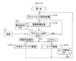
次いで、図1を参照して、サーバ40の構成について説明する。
制御部41は、内部にROM(Read Only Memory)、RAM(Random Access Memory)、CPU(Central Processing Unit)、HDD(Hard Disk Drive)を有し、HDDからオペレーティングシステムOSを読み出してRAM上に展開してOSを起動する。そして、制御部41は、OS管理下において、HDDからアプリケーションソフトウエア(医療画像共有プログラム)を読み出し、各種処理を実行するとともに、サーバ40内の各部を制御する。
通信処理部42は、画像収集装置20やクライアント端末30との間でネットワークNを介してパケットデータを通信する。
Next, the configuration of the
The
The
ストリーミング監視処理部43は、通信処理部42が受信したストリームパケットを監視対処とし、タイムスタンプやフレームを監視することでストリームの途切れを監視する。
共有オブジェクト管理部44は、医療画像において使用される共有オブジェクトを管理する。共有オブジェクトとは、医療画像において使用された情報(例えば、位置決め画像、撮影位置、撮影範囲、撮影条件、画像生成条件、クライアント操作情報(画像位置、文字、引用画像)、レポートに関する情報等)を有効に利用するために、画像情報と付帯(文字または数値)情報とから構成され、例えば検査毎又はシリーズ毎にDICOM規格に従う画像として生成・管理される。
なお、共有オブジェクト管理部44は、情報を共有することを許可されたクライアント端末のみに医療画像情報、及び画像処理結果画像情報を転送することとする。
メッセージ管理部45は、通信処理部42を介してクライアント端末から受信されるメッセージ又はコメントをメッセージDB(図示しない)へ格納する。
The streaming
The shared
Note that the shared
The
ユーザ管理処理部46は、ユーザ管理DB46aに接続され、データ配信サービスを提供しているユーザの認証処理を行う機能を有している。このユーザの認証処理では、クライアント端末30からログイン要求と共に送られてくるユーザ情報(例えば、ユーザID及びパスワード)と、予めユーザ管理DB46aに格納されている各ユーザのユーザ情報との比較照合が行われて、ユーザに対してデータ配信サービスを提供することが可能か否かの判断を行う。
履歴管理処理部47は、履歴管理DB47aに接続され、履歴管理DB47aに蓄積されている配信履歴を医療画像のストリームデータの配信ごとに更新する処理や、不要になった配信履歴を削除する処理などを行う。
The user management processing unit 46 is connected to the
The history
次いで、図2を参照して、ネットワークNを介して行われるメインシーケンスについて説明する。
まず、クライアント端末30では、医療画像共有アプリケーションソフトウエアのアイコンが表示部36aに表示されていることとする。表示画面に表示されているアイコン位置に対して、ユーザの指がタッチされた場合、タッチパッド部36bはタッチがあったことを検出し、かつタッチ位置を検出し操作表示制御部35に出力する。操作表示制御部35では、タッチ位置を制御部31に出力する。さらに、制御部31では、タッチ位置とアイコン位置との関係からこのタッチが医療画像共有アプリケーションソフトウエアのアイコンをクリックしたことを検出する。これにより、医療画像共有アプリケーションソフトウエアがHDDからRAMに展開され、医療画像共有アプリケーションソフトウエアが起動されている。
Next, the main sequence performed via the network N will be described with reference to FIG.
First, in the
医療画像共有アプリケーションソフトウエアが起動されるとブラウザソフトウエアも起動され、ブラウザソフトからの起動命令が通信処理部32に渡される。通信処理部32では、起動命令にヘッダを付加してパケットを生成し、この起動命令をURLコードで示すサーバ40へ送信する。
クライアント端末30から起動命令を受信したサーバ40は、この起動命令を画像収集装置20に送信する。
サーバ40から起動命令を受信した画像収集装置20は、医療機器10から出力される操作及び設定に関連する操作設定画像情報、波形画像情報を含む医療画像情報を入力する。
When the medical image sharing application software is activated, the browser software is also activated, and an activation instruction from the browser software is passed to the communication processing unit 32. The communication processing unit 32 generates a packet by adding a header to the activation command, and transmits the activation command to the
The
The
医療機器10から医療画像情報を入力した画像収集装置20は、A/D変換部21において、画像信号をサンプリングクロックによりサンプリングしてA/D変換することにより、デジタル信号の画像データに変換する。次いで、画像取込部22では、画像データのフレームレートに合わせて順次にフレームメモリに画像データを取り込み、画像エンコーダ部23に出力する。
次いで、画像エンコーダ部23は、符号化方式H.264/AVCに従って画像データを符号化して動画のストリームデータを作成し、ストリーム送出部24に出力する。次いで、ストリーム送出部24は、画像エンコーダ部23から出力される画像ストリームデータを通信処理部27に出力する。
次いで、通信処理部27は、ストリーム送出部24から出力される画像ストリームデータにヘッダを付加してパケット化しネットワークNを介してサーバ40に送信する。
The
Next, the
Next, the communication processing unit 27 adds a header to the image stream data output from the
画像収集装置20から画像ストリームデータを受信したサーバ40は、画像ストリームデータをクライアント端末30に送信する。
この結果、クライアント端末30の表示部36aには、図3に示すような表示画像36cが表示されており、ストリームデータ領域68に画像ストリームデータが表示される。
ここで、図3を参照して、クライアント端末30の表示画面について説明する。
表示画像36cには、ペンアイコン61、イメージ検索アイコン62、検索アイコン63、面積計算タブ64、メッセージ一覧領域65、参加者一覧領域66、未参加ユーザ一覧領域67、ストリームデータ領域68、入力室者表示領域69、クローズアイコン70が表示されている。
ストリームデータ領域68には、図4に示すような、操作及び設定に関連する操作設定画像情報、波形画像情報を含む医療画像情報がリアルタイムで表示されている。
The
As a result, the
Here, a display screen of the
The
In the
次に、図5を参照して、クライアント端末30における医療画像共有アプリケーションソフトウエアの動作を示すフローチャートについて説明する。
ステップS1では、制御部31はログイン画面を表示部36aに表示するように操作表示制御部35し、ログイン画面にIDコード及びパスワードが入力された場合に、ステップS55に進み、入力されたIDコード及びパスワードを含む問合せ要求信号を通信処理部32からネットワークNを介してサーバ40に送信する。
サーバ40において、IDコード及びパスワードが認証された場合に、サーバ40から認証信号がクライアント端末30に返送され、ステップS5に進む。
Next, with reference to FIG. 5, a flowchart showing the operation of the medical image sharing application software in the
In step S1, the
When the
次いで、ステップS5では、制御部31はログアウト状態があれば終了する(S5、Y)。一方、制御部31はログアウト状態がなければ(S5、N)、ステップS10〜S40に進む。
ここで、入力室者表示領域69への入室者の有無を監視する入室監視(S10)、参加者一覧領域66でのユーザ選択を監視するユーザ選択監視(S15)、ストリーミングに対してID管理されているタグ情報を監視するタグ監視(S20)、ペンアイコン61へのタッチ後の描画操作を監視する描画監視(S25)、検索アイコン63へのタッチ後の検索処理を監視する検索監視(S30)、面積計算タブ64へのタッチ後の計測状況を監視する計測監視(S35)、クローズアイコン70へのタッチを監視するログアウト監視(S40)を夫々同時並行して監視している。
次いで、ステップS10〜S35における夫々の監視結果として適合する処理がある場合に、ステップS45に進む。
Next, in step S5, the
Here, ID management is performed for the entrance monitoring (S10) for monitoring the presence or absence of a person entering the input
Next, when there is a process that matches each monitoring result in steps S10 to S35, the process proceeds to step S45.
ステップS45では、制御部31は操作情報が入力された場合に、ステップS55に進み、操作情報を含む機能問合せ要求信号を通信処理部32からネットワークNを介してサーバ40に送信する。
サーバ40において、該機能問合要求信号に応じた返答信号を生成した場合に、サーバ40から返答信号がクライアント端末30に返送され、ステップS50に進む。
ステップS50では、ユーザによる操作に関する操作情報が入力された場合に、ステップS55に進み、共有オブジェクト操作情報を通信処理部32からネットワークNを介してサーバ40に送信する。
サーバ40において、共有オブジェクト操作情報を確認された場合に、サーバ40からオブジェクト操作確認信号がクライアント端末30に返送され、ステップS5に戻る。
In step S45, when the operation information is input, the
When the
In step S50, when the operation information related to the operation by the user is input, the process proceeds to step S55, and the shared object operation information is transmitted from the communication processing unit 32 to the
When the shared object operation information is confirmed in the
次に、図6を参照して、サーバ40における医療画像共有ソフトウエアの動作を示すフローチャートについて説明する。
ステップS101では、制御部41はストリーミング監視処理部43にストリーミング監視処理を行わせる。ここで、ストリーミング監視処理部43では、通信処理部42が受信したストリームパケットを監視対処とし、タイムスタンプやフレームを監視することでストリームの途切れを監視する。
次いで、ステップS105では、制御部41は履歴管理処理部47に履歴管理処理を行わせる。ここで、履歴管理処理部47では、履歴管理DB47aを参照し、履歴管理DB47aに蓄積されている配信履歴を医療画像のストリームデータの配信ごとに更新する処理や、不要になった配信履歴を削除する処理などを行う。
Next, with reference to FIG. 6, a flowchart showing the operation of the medical image sharing software in the
In step S101, the
Next, in step S105, the
次いで、ステップS110では、制御部41は、クライアント端末30からの受信した情報を通信処理部42から取得する。
次いで、ステップS115では、制御部40は、クライアント操作情報を受け付けたか否かを判断する。クライアント操作情報がない場合にはステップS105に進む。一方、クライアント操作情報がログイン情報である場合に、ステップS120に進む。また、クライアント操作情報が情報共有操作である場合に、ステップS125に進む。
次いで、ステップS120では、制御部40はユーザ管理処理部46にユーザ管理処理を行わせる。ここで、ユーザ管理処理部46では、ユーザ管理DB46aを参照し、ログインしたユーザのユーザID及びパスワードがユーザ管理DB46aに登録されているか否かを検索し、ユーザID及び/又はパスワードが不適切な場合はエラーメッセージをクライアント端末に返送する一方、適切な場合はステップS101に戻り、上記処理を繰り返す。なお、ユーザの新規登録についてはその説明を省略する。
次いで、ステップS125では、制御部40は共有オブジェクト管理部44に共有オブジェクト管理を行わせる。ここで、共有オブジェクト管理部44では、医療画像において使用される共有オブジェクトを管理する。
Next, in step S <b> 110, the
Next, in step S115, the
Next, in step S120, the
Next, in step S125, the
次いで、図7(a)を参照して、画面描画シーケンスについて説明する。
ここで、図7(a)に示す画面描画シーケンスには示してないが、画像収集装置20から送信されている画像ストリームデータが、サーバ40を介してクライアント端末30A、30Bに送信されていることとする。これにより、クライアント端末30A、30Bの表示部36aには、図8に示すような表示画像36cが表示されており、ストリームデータ領域68に画像ストリームデータが表示されていることとする。
Next, the screen drawing sequence will be described with reference to FIG.
Here, although not shown in the screen drawing sequence shown in FIG. 7A, the image stream data transmitted from the
まず、クライアント端末30Aでは、表示画面に表示されているペンアイコン61の位置に対して、ユーザの指がタッチされた場合、図5に示す描画監視(S25)に移行する。そして、制御部31は描画に関する操作情報が入力された場合(S45)に、描画操作情報を含む機能問合せ要求信号を通信処理部32からネットワークNを介してサーバ40に送信する(S50)。
ここで、クライアント端末30Aでは、ユーザがタッチパッド部36bにタッチし所望の手書き文字や図形を描いた場合、タッチパネル部36bのタッチ位置を追跡して検出し操作表示制御部35にタッチ位置データ群を出力する。操作表示制御部35では、タッチ位置データ群を画像合成部35aに出力し、画像合成部35aにおいてタッチ位置データ群をVRAM上に描画する。これにより、図8に示すように、例えば長方形図形81aや矢印81bや手書き文字「ココ」81cが描画されて表示部36aに表示される。
一方、操作表示制御部35はタッチ位置データ群を制御部31に出力する。そして、制御部31はタッチ位置データ群を通信処理部32に渡す。通信処理部32では、タッチ位置データ群にヘッダを付加してパケットを生成し、このタッチ位置データ群を描画座標情報としてURLコードで示すサーバ40へ送信する。
First, in the
Here, in the
On the other hand, the operation
クライアント端末30から描画座標情報を受信したサーバ40では、制御部41は現在接続されており、かつ、画像共有相手側のクライアント端末を共有オブジェクト管理部44にチェックさせ、共有オブジェクト管理部44での処理により、現在、例えばクライアント端末30Bが共有相手として接続されていることが確認できた場合に、この描画座標情報をクライアント端末30Bに送信する。
このように、サーバは、情報を共有することを許可されたクライアント端末のみに医療画像情報、及び画像処理結果画像情報を転送することで、情報共有を許可された複数のクライアント端末の間で合成画像を共有することができる。
In the
As described above, the server transfers the medical image information and the image processing result image information only to the client terminals permitted to share the information, thereby combining the plurality of client terminals permitted to share the information. You can share images.
サーバ40から描画座標情報を受信したクライアント端末30Bでは、制御部31は描画座標情報を操作表示制御部35に出力する。操作表示制御部35では、描画座標情報を画像合成部35aに出力し、画像合成部35aにおいて描画座標情報をVRAM上に描画する。
これにより、図8に示すように、例えば長方形図形81aや矢印81bや手書き文字「ココ」81cが描画されて表示部36aに表示される。
この結果、画像収集装置20からサーバ40を介してクライアント端末30A、30Bに送信されている画像ストリームデータの表示画面において、クライアント端末30Aで手書きされた描画画像をクライアント端末30Bにも表示される。このため、例えば医療画像に対して所望の箇所に手書き文字などを描画させ端末間で共有することができる。
In the
Thereby, as shown in FIG. 8, for example, a rectangular figure 81a, an
As a result, on the display screen of the image stream data transmitted from the
次いで、図7(b)を参照して、メッセージ送受信シーケンスについて説明する。
なお、図7(a)に示す画面描画シーケンスでは、手書き描画を行った際にその描画座標をクライアント端末30A、30B間で共有するシーケンスを示したが、図7(b)ではメッセージ送受信シーケンスについて示す。すなわち、クライアント端末30Aでは、表示画面に表示されている対話アイコン71の位置に対して、ユーザの指がタッチされた場合、キーボード(図示しない)を用いて作成したテキストメッセージをメッセージ一覧領域65に一旦保存することができる。そして、クライアント端末30Aからサーバ40にテキストメッセージを送信し、サーバ40から当該テキストメッセージをクライアント端末30Bに送信する。
Next, a message transmission / reception sequence will be described with reference to FIG.
The screen drawing sequence shown in FIG. 7A shows a sequence in which the drawing coordinates are shared between the
この結果、画像収集装置20からサーバ40を介してクライアント端末30A、30Bに送信されている画像ストリームデータの表示画面において、クライアント端末30Aで入力されたテキストデータをクライアント端末30Bにも表示される。このため、例えば医療画像に対してユーザから寄せられたテキストメッセージを端末間で共有することができる。
As a result, on the display screen of the image stream data transmitted from the
このように、医療機器から出力される医療画像情報を収集する画像収集装置と、サーバと、複数のクライアント端末とをネットワークを介して接続し、サーバを介して複数のクライアント端末の間で情報を共有する医療画像共有システムであって、画像収集装置は、医療機器から出力される操作及び設定に関連する操作設定画像情報、医療画像情報を取得し(医療画像情報取得手段)、医療画像情報に対して画像処理を施し(画像処理手段)、医療画像情報と画像処理により得られた画像処理結果画像情報とをサーバに送信し、サーバは、画像収集装置から受信した医療画像情報、及び画像処理結果画像情報を複数のクライアント端末に転送し(転送手段)、クライアント端末は、サーバから医療画像情報と画像処理結果画像情報とを受信し(受信手段)、受信された医療画像情報に画像処理結果画像を合成し(画像合成手段)、合成された合成画像を表示する(表示手段)。これにより、複数のクライアント端末の間で合成画像を共有することができる。
この結果、複数のクライアント端末の間で共有されている合成画像を参照して、メンテナンス説明や機器説明を行うことができ、両者間での情報共有の質が極めて高く、相互に理解し易い状況を提供することができる。
In this way, an image collection device that collects medical image information output from a medical device, a server, and a plurality of client terminals are connected via a network, and information is transmitted between the plurality of client terminals via the server. A medical image sharing system for sharing, wherein an image collection device acquires operation setting image information and medical image information related to operations and settings output from a medical device (medical image information acquisition unit), and stores the medical image information as medical image information. The image processing is performed (image processing means), the medical image information and the image processing result image information obtained by the image processing are transmitted to the server, and the server receives the medical image information received from the image collection device and the image processing. The result image information is transferred to a plurality of client terminals (transfer means), and the client terminal receives the medical image information and the image processing result image information from the server. Receiving means), combined (image synthesizing means the image processing result image on the received medical image information), and displays the synthesized composite image (display means). Thereby, a composite image can be shared among a plurality of client terminals.
As a result, it is possible to perform maintenance explanations and equipment explanations by referring to composite images shared among multiple client terminals, and the quality of information sharing between them is extremely high, making it easy to understand each other Can be provided.
<第2実施形態>
本発明の第2実施形態に係る医療画像共有システムについて説明する。なお、第2実施形態に係る医療画像共有システムは、図1に示す第1実施形態に係る医療画像共有システム1に適用するものである。
まず、図9を参照して、波形検知シーケンスについて説明する。
ここで、図9に示す波形検知シーケンスには示してないが、画像収集装置20から送信されている画像ストリームデータが、サーバ40を介してクライアント端末30A、30Bに送信されていることとする。これにより、クライアント端末30A、30Bの表示部36aには、表示画像36cが表示されており、ストリームデータ領域68に画像ストリームデータが表示されていることとする。
Second Embodiment
A medical image sharing system according to a second embodiment of the present invention will be described. The medical image sharing system according to the second embodiment is applied to the medical
First, the waveform detection sequence will be described with reference to FIG.
Here, although not shown in the waveform detection sequence shown in FIG. 9, it is assumed that the image stream data transmitted from the
図9において、クライアント端末30Aでは、表示画面に表示されているペンアイコン61の位置に対して、ユーザの指がタッチされた場合、図5に示す描画監視(S25)に移行する。そして、制御部31は仮想ラインの描画に関する操作情報が入力された場合(S45)に、描画操作情報を含む機能問合せ要求信号を通信処理部32からネットワークNを介してサーバ40に送信する(S50)。
ここで、クライアント端末30Aでは、ユーザがタッチパッド部36bにタッチし所望の仮想ラインを描いた場合、タッチパネル部36bのタッチ位置を追跡して検出し操作表示制御部35にタッチ位置データ群を出力する。操作表示制御部35では、タッチ位置データ群を画像合成部35aに出力し、画像合成部35aにおいてタッチ位置データ群をVRAM上に描画する。これにより、図11に示すように、例えば仮想ラインとしてLine1、Line2が描画されて表示部36aに表示される。
一方、操作表示制御部35は仮想ラインを示すタッチ位置データ群を制御部31に出力する。そして、制御部31は仮想ラインを示すタッチ位置データ群を通信処理部32に渡す。通信処理部32では、タッチ位置データ群にヘッダを付加してパケットを生成し、この仮想ラインを示すタッチ位置データ群を描画座標情報としてURLコードで示すサーバ40へ送信する。
9, in the
Here, in the
On the other hand, the operation
クライアント端末30から描画座標情報を受信したサーバ40では、制御部41は現在接続されている画像収集装置20に仮想ラインにより示される波形ピーク画像域又はボトムピーク画像域の座標情報を送信する。
サーバ40から仮想ラインにより示される波形ピーク画像域又はボトムピーク画像域の座標情報を受信した画像収集装置20は、交点チェックを行い、波形画像が仮想ラインで示される範囲を逸脱した場合に、ピーク値のインターバルタイミングをサーバ40に送信する。
画像収集装置20からインターバルタイミングを受信したサーバ40は、インターバルタイミングを履歴管理処理部47に出力する。履歴管理処理部47では入力されたインターバルタイミングを履歴管理DB47aに格納する。さらに、サーバ40は、インターバルタイミングをクライアント端末30Aに送信する。
また、画像共有相手側のクライアント端末を共有オブジェクト管理部44にチェックさせ、現在、例えばクライアント端末30Bが共有相手として接続されていることが確認できた場合に、このインターバルタイミングをクライアント端末30Bに送信する。
In the
The
The
In addition, when the shared
サーバ40からインターバルタイミングを受信したクライアント端末30Bでは、制御部31はインターバルタイミングを操作表示制御部35に出力する。操作表示制御部35では、描画座標情報を画像合成部35aに出力し、画像合成部35aにおいて描画座標情報をVRAM上に描画する。これにより、図11に示すように、例えば仮想ラインとしてLine1、Line2が描画されて表示部36aに表示される。
In the
インターバルタイミングとしては、図11に示すように、「インターバルタイム( )Sec」というメッセージとともに、「警告:インターバル時間が設定をオーバー」という警告メッセージ画像がストリームデータ領域68に合成されて表示される。
この結果、画像収集装置20からサーバ40を介してクライアント端末30A、30Bに送信されている画像ストリームデータの表示画面において、クライアント端末30AでLine1、Line2の描画画像をクライアント端末30Bにも表示される。このため、例えば医療画像に対して所望の箇所に仮想ラインを描画させ端末間で共有することができる。
As the interval timing, as shown in FIG. 11, a message “interval time () Sec” and a warning message image “warning: interval time is over” are combined and displayed in the
As a result, on the display screen of the image stream data transmitted from the
次いで、図10を参照して、画像収集装置20において波形検知処理を実行するためのフローチャートについて説明する。
サーバ40から仮想ラインにより示される波形ピーク画像域又はボトムピーク画像域の座標情報を受信した画像収集装置20は、通信処理部27から画像処理部26に波形ピーク画像域又はボトムピーク画像域を出力する。
まず、ステップS151では、画像処理部26は、波形ピーク画像域又はボトムピーク画像域を閾値1、閾値2としてメモリ26aに記憶することにより設定する。
次いで、ステップS155では、画像処理部26は、画像エンコーダ部23から画像を取り込みメモリ26aに書き込む。
次いで、ステップS160では、画像処理部26は、メモリ26aに取り込んだ画像のリサイズ処理、すなわち、画像の縮小、拡大を縦方向及び横方向で行う。
Next, a flowchart for executing the waveform detection process in the
The
First, in step S151, the
Next, in step S155, the
Next, in step S160, the
次いで、ステップS165では、画像処理部26は、メモリ26aでリサイズ処理を施した画像(多値)に対して、画像の2値化処理を行い、処理結果となる2値画像をメモリ26aの他の領域に記憶する。
次いで、ステップS170では、画像処理部26は、メモリ26aの他の領域に記憶された2値画像に対して、閾値1、閾値2を基準にして閾値判断処理を行う。すなわち、閾値判断処理では特定ピクセル(画素)が閾値1又は閾値2と衝突しているか否かを判定する衝突判定処理を行う。
Next, in step S165, the
Next, in step S170, the
ここで、閾値1又は閾値2と衝突している場合(S170、Y)、ステップS175に進み、アラート処理を行う。アラート処理では、上述したインターバルタイミングとして、「Line1オーバー」、「Line2オーバー」というメッセージとともに、時刻データとして「21:01:15/01/07/2013」という画像を生成する。ステップS180では、このようなインターバルタイミングを監視データとして通信処理部27からサーバ40に送信する。
また、アラート処理では、「警告:インターバル時間が設定をオーバー」という警告メッセージ画像を生成してもよい。
ステップS185では、終了判断処理を行う。すなわち、サーバ40から画像収集装置20に終了信号が送信され、通信処理部27から画像処理部26に終了信号が引き渡された場合に処理を終了する。一方、波形検知処理を継続する場合(S185、N)にはステップS155に戻り、上述した処理を繰り返す。
Here, when it collides with the
In the alert process, a warning message image “warning: interval time is over setting” may be generated.
In step S185, end determination processing is performed. That is, when the end signal is transmitted from the
このように、画像処理部は、クライアント端末から医療画像情報中の波形画像情報に含まれる波形の位置を示す位置情報を受信し、波形画像情報に含まれる波形領域に対して、クライアント端末から受信された位置情報を閾値となる少なくとも1つの仮想ラインとして設定し、描画される波形が該仮想ラインで示される範囲を逸脱するか否かを判断し、描画される波形が該仮想ラインで示される範囲を逸脱した場合に警報を発生する(警報発生手段)。これにより、クライアント端末からの指示に応じて少なくとも1つの仮想ラインを設定でき、描画される波形が該仮想ラインで示される範囲を逸脱した場合に警告を発生することができ、クライアント端末では指示した位置(閾値)を波形が逸脱したことを警報により確認することができる。これに加えて、仮想ラインは同様に、ピーク値のインターバルタイミングを設定することで、波形の時刻的パターンから逸脱する場合にアラームを発する機能も有し、異常なパターンを検知することもできる。 As described above, the image processing unit receives position information indicating the position of the waveform included in the waveform image information in the medical image information from the client terminal, and receives from the client terminal the waveform region included in the waveform image information. The set position information is set as at least one virtual line serving as a threshold, it is determined whether or not the waveform to be drawn deviates from the range indicated by the virtual line, and the waveform to be drawn is indicated by the virtual line An alarm is generated when the value deviates from the range (alarm generating means). Accordingly, at least one virtual line can be set according to an instruction from the client terminal, and a warning can be generated when the waveform to be drawn deviates from the range indicated by the virtual line. It can be confirmed by an alarm that the waveform deviates from the position (threshold). In addition to this, the virtual line similarly has a function of issuing an alarm when it deviates from the time pattern of the waveform by setting the interval timing of the peak value, and can detect an abnormal pattern.
また、画像処理結果データをサーバに送信し、サーバを介して1又は複数のクライアント端末に当該画像処理結果データ(警告メッセージ)を送信することで、複数のクライアント端末の間で合成画像(警告メッセージ)を共有することができる。また画像収集装置とクライアント端末との間で医療画像情報を共有することができる。
この結果、複数のクライアント端末の間で共有されている合成画像を参照して、メンテナンス説明や機器説明を行うことができ、両者間での情報共有の質が極めて高く、相互に理解し易い状況を提供することができる。
In addition, the image processing result data is transmitted to the server, and the image processing result data (warning message) is transmitted to one or a plurality of client terminals via the server, so that a composite image (warning message) is transmitted between the plurality of client terminals. ) Can be shared. Further, medical image information can be shared between the image collection device and the client terminal.
As a result, it is possible to perform maintenance explanations and equipment explanations by referring to composite images shared among multiple client terminals, and the quality of information sharing between them is extremely high, making it easy to understand each other Can be provided.
<第3実施形態>
本発明の第3実施形態に係る医療画像共有システムについて説明する。なお、第3実施形態に係る医療画像共有システムは、図1に示す第1実施形態に係る医療画像共有システム1に適用するものである。
まず、図12を参照して、面積測定シーケンスについて説明する。
ここで、図12に示す面積測定シーケンスには示してないが、画像収集装置20から送信されている画像ストリームデータが、サーバ40を介してクライアント端末30A、30Bに送信されていることとする。これにより、クライアント端末30A、30Bの表示部36aには、表示画像36cが表示されており、ストリームデータ領域68に画像ストリームデータが表示されていることとする。
<Third Embodiment>
A medical image sharing system according to a third embodiment of the present invention will be described. The medical image sharing system according to the third embodiment is applied to the medical
First, the area measurement sequence will be described with reference to FIG.
Here, although not shown in the area measurement sequence illustrated in FIG. 12, it is assumed that the image stream data transmitted from the
図12において、クライアント端末30Aでは、表示画面に表示されているペンアイコン61の位置に対して、ユーザの指がタッチされた場合、図5に示す描画監視(S25)に移行する。そして、制御部31はペンにより指定される所望の面積を示す閉ループの描画に関する操作情報が入力された場合(S45)に、描画操作情報を含む機能問合せ要求信号を通信処理部32からネットワークNを介してサーバ40に送信する(S50)。
ここで、クライアント端末30Aでは、ユーザがタッチパッド部36bにペンによりタッチし所望の閉ループを描いた場合、タッチパネル部36bのタッチ位置を追跡して検出し操作表示制御部35にタッチ位置データ群を出力する。操作表示制御部35では、タッチ位置データ群を画像合成部35aに出力し、画像合成部35aにおいてタッチ位置データ群をVRAM上に描画する。これにより、図14に示すように、例えば所望の面積を示す閉ループ81が描画されて表示部36aに表示される。また、図15(a)は処理前の様子を示す図であり、図15(b)に示すように、例えば所望の面積を示す閉ループ68aが描画されて表示部36aに表示される。
In FIG. 12, in the
Here, in the
一方、操作表示制御部35は所望の閉ループを示すタッチ位置データ群を制御部31に出力する。そして、制御部31は所望の閉ループを示すタッチ位置データ群を通信処理部32に渡す。通信処理部32では、タッチ位置データ群にヘッダを付加してパケットを生成し、この所望の閉ループを示すタッチ位置データ群を描画座標情報としてURLコードで示すサーバ40へ送信する。
On the other hand, the operation
クライアント端末30からペンにより描画された描画座標情報を受信したサーバ40では、制御部41は現在接続されている画像収集装置20に所望の閉ループにより示される画像範囲の座標情報を送信する。
サーバ40からペンにより描画された画像範囲の座標情報を受信した画像収集装置20は、領域のピクセル数の探索を行い、時刻データを付加した領域のピクセル数データをサーバ40に送信する。
画像収集装置20から領域のピクセル数データを受信したサーバ40は、領域のピクセル数データを履歴管理処理部47に出力する。履歴管理処理部47では入力された領域のピクセル数データを履歴管理DB47aに格納する。さらに、サーバ40は、領域のピクセル数を面積データとしてクライアント端末30Aに送信する。
なお、面積はdpi2で表し、医療画像の実際のサイズであれば、mm単位で表すこととする。
また、画像共有相手側のクライアント端末を共有オブジェクト管理部44にチェックさせ、現在、例えばクライアント端末30Bが共有相手として接続されていることが確認できた場合に、この面積データをクライアント端末30Bに送信する。
In the
The
The
The area is represented by dpi 2 and, if the actual size of the medical image is represented, it is represented in mm.
Further, when the shared
サーバ40から面積データを受信したクライアント端末30Bでは、制御部31はインターバルタイミングを操作表示制御部35に出力する。操作表示制御部35では、描画座標情報を画像合成部35aに出力し、画像合成部35aにおいて描画座標情報をVRAM上に描画する。これにより、図14に示すように、例えば所望の閉ループ81が描画されて表示部36aに表示される。
面積データとしては、図14に示すように、面積計算タブ64内の表示ボックスに面積データがテキスト化された画像がストリームデータ領域68の左側部に合成されて表示される。
この結果、画像収集装置20からサーバ40を介してクライアント端末30A、30Bに送信されている画像ストリームデータの表示画面において、クライアント端末30Aで所望の閉ループ81の描画画像をクライアント端末30Bにも表示される。このため、例えば医療画像に対して所望の箇所に閉ループを描画させ端末間で共有することができる。
In the
As the area data, as shown in FIG. 14, an image in which the area data is converted into text is combined and displayed on the left side of the
As a result, on the display screen of the image stream data transmitted from the
次いで、図13を参照して、面積測定処理を実行するためのフローチャートについて説明する。
サーバ40からペンにより描画された座標情報を受信した画像収集装置20は、通信処理部27から画像処理部26にペン指定情報および閉領域描画指示を出力する。一方、画像処理部26は、画像エンコーダ部23から画像を取り込みメモリ26aに書き込む。
まず、ステップS201では、画像処理部26は、ペンが指定されたことを設定する。
次いで、ステップS205では、画像処理部26は、メモリ26aに書き込んだ画像に対して、受信した描画座標情報に応じて閉領域を描画する。描画されたペンの軌跡の末端が始点と重なることで閉領域が形成された方が好ましい。
Next, a flowchart for executing the area measurement process will be described with reference to FIG.
Receiving the coordinate information drawn by the pen from the
First, in step S201, the
Next, in step S205, the
そこで、ステップS210では、画像処理部26は、メモリ26aに描画されたペンの軌跡の末端と始点とが閉領域になっていないか否かを判断する。ペンの軌跡の末端と始点とが閉領域になっていない場合(S210、Y)はステップS215に進む。
次いで、ステップS215では、画像処理部26は、ペンの軌跡の末端と始点とを接続することにより閉領域を形成する。
次いで、ステップS220では、画像処理部26は、メモリ26aに描画された閉領域内のピクセル数を算出する。
次いで、ステップS225では、画像処理部26は、ピクセル数をテキストメッセージに変換し、さらに、テキストメッセージをストリームデータに変換し、通信処理部27に出力する。
この結果、図14に示すように、面積計算タブ64内の表示ボックスに面積データがテキスト化された画像がストリームデータ領域68の左側部に合成されて表示される。
Therefore, in step S210, the
Next, in step S215, the
Next, in step S220, the
In step S225, the
As a result, as shown in FIG. 14, an image in which the area data is converted into text is synthesized and displayed on the left side of the
このように、画像処理部は、クライアント端末から医療画像情報中の画像情報の範囲を指定する指定範囲情報を受信し、クライアント端末から受信された指定範囲情報が示す範囲に含まれる医療画像情報の画素数から面積を算出する(面積算出手段)。これにより、クライアント端末から指定された範囲の面積を算出することができ、クライアント端末では当該面積を確認することができる。
また、画像処理結果データをサーバに送信し、サーバを介して1又は複数のクライアント端末に当該画像処理結果データ(面積)を送信することで、複数のクライアント端末の間で合成画像を共有することができ、また画像収集装置とクライアント端末との間で医療画像情報を共有することができる。
この結果、複数のクライアント端末の間で共有されている合成画像を参照して、メンテナンス説明や機器説明を行うことができ、両者間での情報共有の質が極めて高く、相互に理解し易い状況を提供することができる。
In this way, the image processing unit receives the specified range information that specifies the range of the image information in the medical image information from the client terminal, and the medical image information included in the range indicated by the specified range information received from the client terminal. An area is calculated from the number of pixels (area calculation means). Thereby, the area of the range designated from the client terminal can be calculated, and the area can be confirmed in the client terminal.
Also, by transmitting the image processing result data to the server and transmitting the image processing result data (area) to one or a plurality of client terminals via the server, the composite image is shared among the plurality of client terminals. Medical image information can be shared between the image collection device and the client terminal.
As a result, it is possible to perform maintenance explanations and equipment explanations by referring to composite images shared among multiple client terminals, and the quality of information sharing between them is extremely high, making it easy to understand each other Can be provided.
<第4実施形態>
本発明の第4実施形態に係る医療画像共有システムについて説明する。なお、第4実施形態に係る医療画像共有システムは、図1に示す第1実施形態に係る医療画像共有システム1に適用するものである。
まず、図16を参照して、文字検索シーケンスについて説明する。
ここで、図12に示す文字検索シーケンスには示してないが、画像収集装置20から送信されている画像ストリームデータが、サーバ40を介してクライアント端末30A、30Bに送信されていることとする。これにより、クライアント端末30A、30Bの表示部36aには、表示画像36cが表示されており、ストリームデータ領域68に画像ストリームデータが表示されていることとする。
<Fourth embodiment>
A medical image sharing system according to a fourth embodiment of the present invention will be described. The medical image sharing system according to the fourth embodiment is applied to the medical
First, a character search sequence will be described with reference to FIG.
Here, although not shown in the character search sequence shown in FIG. 12, it is assumed that the image stream data transmitted from the
図16において、クライアント端末30Aでは、表示画面に表示されている検索アイコン63の位置に対して、ユーザの指がタッチされた場合、図5に示す検索監視(S30)に移行する。そして、制御部31は検索アイコン63へのタッチに続いて、キーボードにより候補となる所望の文字列情報が入力された場合(S45)に、描画操作情報を含む機能問合せ要求信号を通信処理部32からネットワークNを介してサーバ40に送信する(S50)。
ここで、クライアント端末30Aでは、図18に示すように、例えば波形画像とともに医療機器の操作ボタンや操作画面を示す画像領域85、86として例えば「V_Level □up」「V_Level □down」が描画されている画像がストリームデータ領域68内に表示される。また、図19(a)に示すように、例えば文字画像「ABCD・・・」を含む画像領域87が表示画像36cとして表示される。
16, in the
Here, in the
一方、操作表示制御部35は検索要求や所望の候補となる文字列を示す検索文字データを制御部31に出力する。そして、制御部31は所望の検索文字データを通信処理部32に渡す。通信処理部32では、検索文字データにヘッダを付加してパケットを生成し、この所望の検索文字データをURLコードで示すサーバ40へ送信する。
On the other hand, the operation
クライアント端末30から検索文字データを受信したサーバ40では、制御部41は現在接続されている画像収集装置20に文字列データを送信する。
サーバ40から文字列データを受信した画像収集装置20は、画面内の医療画像から文字判断を行い、文字列が一致した場合にTrue文字位置データをサーバ40に送信する。
画像収集装置20からTrue文字位置データを受信したサーバ40は、True文字位置データを履歴管理処理部47に出力する。履歴管理処理部47では入力されたTrue文字位置データを履歴管理DB47aに格納する。
In the
The
The
さらに、サーバ40は、True文字位置データに基づいて、文字範囲を示す枠画像データ88を矩形描画し、枠画像データをクライアント端末30Aに送信する。
また、画像共有相手側のクライアント端末を共有オブジェクト管理部44にチェックさせ、現在、例えばクライアント端末30Bが共有相手として接続されていることが確認できた場合に、この枠画像データをクライアント端末30Bに送信する。
Further, the
Also, when the shared
サーバ40から枠画像データを受信したクライアント端末30Bでは、制御部31は枠画像データを操作表示制御部35に出力する。操作表示制御部35では、枠画像データを画像合成部35aに出力し、画像合成部35aにおいて枠画像データをVRAM上に描画する。これにより、図19に示すように、例えば操作ボタン「XYZ・・・」を囲む枠画像データ88が描画されて表示部36aに表示される。
枠画像データとしては、図19(b)に示すように、枠画像データ88がストリームデータ領域68内に合成されて表示される。
この結果、画像収集装置20からサーバ40を介してクライアント端末30A、30Bに送信されている画像ストリームデータの表示画面において、クライアント端末30Aで所望の文字列を含む枠画像データをストリームデータに合成してクライアント端末30Bにも表示される。このため、例えば医療画像に対して所望の文字列を含む枠画像データを描画させ端末間で共有することができる。
In the
As the frame image data, the
As a result, on the display screen of the image stream data transmitted from the
次いで、図17を参照して、文字検索処理を実行するためのフローチャートについて説明する。
サーバ40から文字列データを受信した画像収集装置20は、通信処理部27から画像処理部26に文字列データを出力する。画像処理部26は、文字列データをメモリ26aに記憶する。
まず、ステップS251では、画像処理部26は、画像エンコーダ部23から画像を取り込みメモリ26aに書き込む。
次いで、ステップS255では、画像処理部26は、メモリ26aに取り込んだ画像(多値)に対して、画像の2値化処理を行い、処理結果となる2値画像をメモリ26aの他の領域に記憶する。ここで、メモリ26aに記憶されている2値画像の座標は左上端部のxy座標を(0,0)を原点とし、右下端部のxy座標を(xe,ye)として扱うこととする。
Next, a flowchart for executing the character search process will be described with reference to FIG.
The
First, in step S251, the
Next, in step S255, the
次いで、ステップS260では、画像処理部26は、メモリ26aに記憶されている2値画像に対して、上記原点から水平(x)方向に1ピクセル移動する。
次いで、ステップS265では、画像処理部26は、水平方向に連続して有効なピクセルが存在することを示す線形ピクセルを発見したか否かを判断する。
線形ピクセルがない場合(S265、N)、ステップS270に進み、画像処理部26は、Xシフトの末端(xe)か否かを判断する。Xシフトの末端(xe)ではない場合(S270、N)、ステップS260に戻り、上述した処理を繰り返す。
一方、Xシフトの末端(xe)である場合(S270、Y)、ステップS275に進み、画像処理部26は、垂直(Y)方向に1ピクセル移動し、ステップS260に戻り、上述した処理を繰り返す。
Next, in step S260, the
Next, in step S <b> 265, the
When there is no linear pixel (S265, N), the process proceeds to step S270, and the
On the other hand, if it is the end (x e ) of the X shift (S270, Y), the process proceeds to step S275, the
一方、線形ピクセルを発見した場合(S265、Y)、ステップS280に進み、線形のクラスタリング処理を施す。すなわち、線形のクラスタリング処理では、位置情報に基づいて領域分割を実施することができる。
次いで、ステップS285では、画像処理部26は、周知のOCR判断器により文字認識処理を行う。
次いで、ステップS290では、画像処理部26は、単体文字のXY座標のMaxSquarのe値をメモリ26aに記憶する。
次いで、ステップS295では、画像処理部26は、文字列(連続文字が発見される限りセット)をメモリ26aに記憶する。
次いで、ステップS300では、画像処理部26は、MaxSquar値が前回の値と異なるか否かを判断する。
On the other hand, when a linear pixel is found (S265, Y), the process proceeds to step S280, and linear clustering processing is performed. That is, in the linear clustering process, the region division can be performed based on the position information.
Next, in step S285, the
Next, in step S290, the
Next, in step S295, the
Next, in step S300, the
MaxSquar値が前回の値と異なる場合(S300、Y)、ステップS305に進み、画像処理部26は、MaxSquar値を更新し、メモリ26aに記憶する。
次いで、ステップS310では、画像処理部26は、連続文字に対して、ラベリング処理を行い、連続文字に関連付けてラベル#kを付与し、ステップS260に戻り、上述した処理を繰り返す。
一方、MaxSquar値が前回の値と同じ場合(S300、N)、ステップS260に戻り、上述した処理を繰り返す。
If the MaxSquar value is different from the previous value (S300, Y), the process proceeds to step S305, and the
Next, in step S310, the
On the other hand, when the MaxSquar value is the same as the previous value (S300, N), the process returns to step S260 and the above-described processing is repeated.
このように、画像処理部は、クライアント端末から医療画像情報に含まれる文字情報の範囲を示す指定範囲情報を受信し、クライアント端末から受信された指定範囲情報が示す範囲に含まれる医療画像情報に対して、先頭の一文字の領域を検出し、検出された一文字の領域に隣接して存在する文字列の領域を検出し、検出された文字領域情報をOCR判断器にて文字解析を行う(文字列検索手段)。これにより、クライアント端末から指定された範囲の画像に含まれている文字を解析することができ、クライアント端末では当該文字を確認することができる。 As described above, the image processing unit receives the specified range information indicating the range of the character information included in the medical image information from the client terminal, and adds the medical image information included in the range indicated by the specified range information received from the client terminal. On the other hand, the area of the first character is detected, the area of the character string existing adjacent to the detected one character area is detected, and the detected character area information is analyzed by the OCR discriminator (character Column search means). Thereby, the character contained in the image of the range designated from the client terminal can be analyzed, and the client terminal can confirm the character.
また、画像処理結果データ(文字)をサーバに送信し、サーバを介して1又は複数のクライアント端末に当該画像処理結果データを送信する。これにより、複数のクライアント端末の間で合成画像を共有することができ、また画像収集装置とクライアント端末との間で医療画像情報を共有することができる。
この結果、複数のクライアント端末の間で共有されている合成画像を参照して、メンテナンス説明や機器説明を行うことができ、両者間での情報共有の質が極めて高く、相互に理解し易い状況を提供することができる。
Further, the image processing result data (characters) is transmitted to the server, and the image processing result data is transmitted to one or a plurality of client terminals via the server. Thereby, a composite image can be shared among a plurality of client terminals, and medical image information can be shared between the image collection device and the client terminal.
As a result, it is possible to perform maintenance explanations and equipment explanations by referring to composite images shared among multiple client terminals, and the quality of information sharing between them is extremely high, making it easy to understand each other Can be provided.
<第5実施形態>
本発明の第5実施形態に係る医療画像共有システムについて説明する。なお、第5実施形態に係る医療画像共有システムは、図1に示す第1実施形態に係る医療画像共有システム1に適用するものである。
まず、図20を参照して、パターン検索シーケンスについて説明する。
ここで、図20に示すパターン検索シーケンスには示してないが、画像収集装置20から送信されている画像ストリームデータが、サーバ40を介してクライアント端末30A、30Bに送信されていることとする。これにより、クライアント端末30A、30Bの表示部36aには、表示画像36cが表示されており、ストリームデータ領域68に画像ストリームデータが表示されていることとする。
<Fifth Embodiment>
A medical image sharing system according to a fifth embodiment of the present invention will be described. The medical image sharing system according to the fifth embodiment is applied to the medical
First, the pattern search sequence will be described with reference to FIG.
Here, although not shown in the pattern search sequence shown in FIG. 20, it is assumed that the image stream data transmitted from the
図20において、クライアント端末30Aでは、表示画面に表示されている検索アイコン63の位置に対して、ユーザの指がタッチされた場合、図5に示す検索監視(S30)に移行する。そして、制御部31は検索アイコン63がタッチされたことに伴う所望の検索用イメージが、例えばドラッグ操作やキーボードにより入力された場合(S45)に、描画操作情報を含む機能問合せ要求信号を通信処理部32からネットワークNを介してサーバ40に送信する(S50)。
ここで、クライアント端末30Aでは、図21に示すように、例えば医療機器の操作ボタンや操作画面の一部の形状を示す検索用イメージ91が描画されて表示画像36cとして表示される。図21には、「0.0kV」という検索用イメージが表示された様子を示す。
20, in the
Here, in the
一方、操作表示制御部35は検索指示と検索用イメージデータを制御部31に出力する。そして、制御部31は検索指示と検索用イメージデータを通信処理部32に渡す。通信処理部32では、検索指示と検索用イメージデータにヘッダを付加してパケットを生成し、この検索指示と検索用イメージデータをURLコードで示すサーバ40へ送信する。
On the other hand, the operation
クライアント端末30から検索指示と検索用イメージデータを受信したサーバ40では、制御部41は現在接続されている画像収集装置20に検索指示と検索用イメージデータを送信する。
サーバ40から検索指示と検索用イメージデータを受信した画像収集装置20は、検索用イメージデータを参照して画面内の医療画像とのパターンマッチング処理を行い、二乗誤差が最小値を示すTrue座標位置データをサーバ40に送信する。
In the
The
画像収集装置20からTrue座標位置データを受信したサーバ40は、True座標位置データを履歴管理処理部47に出力する。履歴管理処理部47では入力されたTrue座標位置データを履歴管理DB47aに格納する。さらに、サーバ40は、True座標位置データに基づいて、文字範囲を示す枠画像データ88を矩形描画し、枠画像データをクライアント端末30Aに送信する。
また、画像共有相手側のクライアント端末を共有オブジェクト管理部44にチェックさせ、現在、例えばクライアント端末30Bが共有相手として接続されていることが確認できた場合に、この枠画像データをクライアント端末30Bに送信する。
The
Also, when the shared
サーバ40から枠画像データを受信したクライアント端末30Bでは、制御部31は枠画像データを操作表示制御部35に出力する。操作表示制御部35では、枠画像データを画像合成部35aに出力し、画像合成部35aにおいて枠画像データをVRAM上に描画する。これにより、図23に示すように、例えば枠画像データ92が描画されて表示部36aに表示される。
枠画像データとしては、図23に示すように、枠画像データ92がストリームデータ領域68内に合成され、「0.0kV」とともに枠画像データ92が表示される。
In the
As the frame image data, as shown in FIG. 23, the
この結果、画像収集装置20からサーバ40を介してクライアント端末30A、30Bに送信されている画像ストリームデータの表示画面において、クライアント端末30Aで所望の検索用イメージを含む枠画像データをストリームデータに合成してクライアント端末30Bにも表示される。このため、例えば医療画像に対して所望の検索用イメージを含む枠画像データを描画させ端末間で共有することができる。
As a result, in the display screen of the image stream data transmitted from the
次いで、図22を参照して、パターン検索処理を実行するためのフローチャートについて説明する。
サーバ40から検索指示と検索用イメージデータを受信した画像収集装置20は、通信処理部27から画像処理部26に検索指示と検索用イメージデータを出力する。画像処理部26は、検索指示と検索用イメージデータをメモリ26aに記憶する。
まず、画像処理部26は、画像エンコーダ部23から画像を取り込みメモリ26aに書き込む。
次いで、ステップS351では、画像処理部26は、メモリ26aに記憶されている画像の座標は左上端部のxy座標を(0,0)を原点とし、右下端部のxy座標を(xe,ye)とし、発見範囲(0,0)〜(xe,ye)を定義する。
次いで、ステップS355では、画像処理部26は、原点(0,0)から(xe,ye)に向かう範囲において、メモリ26aに記憶されている検索用イメージデータに対して、特定位置での二乗誤差を算出し、算出後の二乗誤差データにラベル#kをその都度更新して付加し、メモリ26aに記憶する。
Next, with reference to FIG. 22, a flowchart for executing the pattern search process will be described.
The
First, the
Next, in step S351, the
Next, in step S355, the
次いで、ステップS360では、画像処理部26は、メモリ26aに記憶されている検索用イメージデータに対して、回転を考慮しつつRGBの夫々の画像に対して二乗誤差を計算し、算出後の二乗誤差データにラベル#kRGBをその都度更新して付加し、メモリ26aに記憶する。
次いで、ステップS365では、画像処理部26は、発見範囲(0,0)〜(xe,ye)内の領域ピクセル内での探索を行うため、特定位置を発見範囲内で1ピクセル移動し、ステップS355に戻り、上述した処理を繰り返す。
次いで、ステップS370では、画像処理部26は、メモリ26aから今回算出した二乗誤差Diffを読み出し、二乗誤差Diffが小さい方を仮に最新の最小二乗誤差minDiffとする。
画像処理部26は、二乗誤差sDiffが最小二乗誤差minDiffよりも小さいか否かを判断する。
Next, in step S360, the
Next, in step S365, the
In step S370, the
The
sDiff<minDiff
ここで、二乗誤差sDiffが最小二乗誤差minDiffよりも小さい場合(S370、Y)は、ステップS375に進み、二乗誤差sDiff=最小二乗誤差minDiffとなる位置を特定し、メモリ26aにその座標範囲(xsk,ysk)〜(xek,yek)を記憶する。
一方、二乗誤差sDiffが最小二乗誤差minDiffよりも小さくない場合(S370、N)は、ステップS380に進み、発見範囲(0,0)〜(xe,ye)内でスケール数分の二乗誤差の算出を繰り返すため、ステップS351に戻り、上述した処理を繰り返す。
この繰り返し処理により、ステップS370で算出される最小二乗誤差minDiffが徐々に小さい値に置き換えられていく。
ステップS380での繰り返し処理が終了した場合に、ステップS385に進み、二乗誤差の最小値を決定し、メモリ26aからその座標範囲(xsk,ysk)〜(xek,yek)を読み出す。
sDiff <minDiff
Here, when the square error sDiff is smaller than the minimum square error minDiff (S370, Y), the process proceeds to step S375, the position where the square error sDiff = the minimum square error minDiff is specified, and the coordinate range (x sk , y sk ) to (x ek , y ek ) are stored.
On the other hand, when the square error sDiff is not smaller than the minimum square error minDiff (S370, N), the process proceeds to step S380, and the square error corresponding to the number of scales within the discovery range (0, 0) to (x e , y e ). In order to repeat the calculation, the process returns to step S351 to repeat the above-described processing.
By this iterative process, the least square error minDiff calculated in step S370 is gradually replaced with a smaller value.
When the repetitive processing in step S380 is completed, the process proceeds to step S385, determines the minimum value of the square error, the coordinate range from the memory 26a (x sk, y sk) ~ (x ek, y ek) read out.
このように、画像処理部は、クライアント端末から画像パターンを受信し、医療画像情報を2次元平面に展開し、該2次元平面上の発見範囲内の領域を移動し、クライアント端末から受信された画像パターンと該領域内の画像情報との二乗誤差を算出して記憶し、該記憶された二乗誤差が最小となる画像情報を画像パターンとして決定する(テンプレート解析手段)。これにより、クライアント端末から指定された画像パターンに最も近い画像情報の位置を決定することができ、クライアント端末では指定した画像パターンに最も近い画像情報の位置を確認することができる。 In this way, the image processing unit receives the image pattern from the client terminal, expands the medical image information on the two-dimensional plane, moves the region within the discovery range on the two-dimensional plane, and is received from the client terminal A square error between the image pattern and the image information in the region is calculated and stored, and the image information that minimizes the stored square error is determined as an image pattern (template analysis unit). Thereby, the position of the image information closest to the image pattern specified from the client terminal can be determined, and the position of the image information closest to the specified image pattern can be confirmed at the client terminal.
また、画像処理結果データをサーバに送信し、サーバを介して1又は複数のクライアント端末に当該画像処理結果データ(画像情報の位置)を送信することで、複数のクライアント端末の間で合成画像を共有することができる。また画像収集装置とクライアント端末との間で医療画像情報を共有することができる。
この結果、複数のクライアント端末の間で共有されている合成画像を参照して、メンテナンス説明や機器説明を行うことができ、両者間での情報共有の質が極めて高く、相互に理解し易い状況を提供することができる。
Also, the image processing result data is transmitted to the server, and the image processing result data (position of image information) is transmitted to one or a plurality of client terminals via the server, so that a composite image can be obtained between the plurality of client terminals. Can be shared. Further, medical image information can be shared between the image collection device and the client terminal.
As a result, it is possible to perform maintenance explanations and equipment explanations by referring to composite images shared among multiple client terminals, and the quality of information sharing between them is extremely high, making it easy to understand each other Can be provided.
<他の実施形態>
上述した第1〜第5実施形態にあっては、図1に示すように、医療機器10から出力される医療画像情報を収集する画像収集装置20と、サーバ40と、複数のクライアント端末30とをネットワークNを介して接続し、サーバ40を介して複数のクライアント端末30の間で情報を共有する医療画像共有システム1について説明した。
しかしながら、本発明はそのようなシステム構成に限定されるものではない。
すなわち、他の実施形態として、医療機器10から出力される医療画像情報を収集する画像収集装置20と、サーバ40と、クライアント端末30とをネットワークNを介して接続し、サーバ40を介して画像収集装置20とクライアント端末30との間で情報を共有する医療画像共有システムであってもよい。
<Other embodiments>
In the first to fifth embodiments described above, as shown in FIG. 1, an
However, the present invention is not limited to such a system configuration.
That is, as another embodiment, the
詳しくは、画像収集装置20において、画像取込部22に取り込んだ画像を順次に記憶するVRAMを有する表示制御部(図示しない)と、表示制御部のVRAMからフレームレートで読み出した画像を表示するモニタを設ける。さらに、医療画像情報と画像処理結果画像情報とを合成する画像合成部を表示制御部に設けるように構成する。
画像収集装置20において、クライアント端末30から通信処理部27を介して医療画像情報に対する画像処理に関連した指示情報を受信した場合に、この指示情報に基づいて画像処理部26が画像処理を行い、画像処理部26から画像処理結果画像情報を表示制御部に設けられた画像合成部に出力する。そして、医療画像情報と画像処理結果画像情報とを画像合成部により合成し、モニタに出力する。
Specifically, in the
In the
このように、医療機器から出力される医療画像情報を収集する画像収集装置と、サーバと、クライアント端末とをネットワークを介して接続し、サーバを介して画像収集装置とクライアント端末との間で情報を共有する医療画像共有システムであって、画像収集装置は、医療機器から出力される操作及び設定に関連する操作設定画像情報、医療画像情報を取得し(医療画像情報取得手段)、医療画像情報に対して画像処理を施し(画像処理手段)、医療画像情報と画像処理により得られた画像処理結果画像情報とをサーバに送信し(送信手段)、サーバは、画像収集装置から受信した医療画像情報、及び画像処理結果画像情報をクライアント端末に転送し(転送手段)、クライアント端末は、サーバから医療画像情報と画像処理結果画像情報とを受信し(受信手段)、受信された医療画像情報に画像処理結果画像を合成し(画像合成手段)、合成された合成画像を表示する(表示手段)。これにより、画像収集装置とクライアント端末との間で医療画像情報を共有することができる。
この結果、画像収集装置とクライアント端末の間で共有されている合成画像を参照して、メンテナンス説明や機器説明を行うことができ、両者間での情報共有の質が極めて高く、相互に理解し易い状況を提供することができる。
In this way, an image collection device that collects medical image information output from a medical device, a server, and a client terminal are connected via a network, and information is transmitted between the image collection device and the client terminal via the server. The image collection device acquires operation setting image information and medical image information related to operations and settings output from a medical device (medical image information acquisition unit), and medical image information Is subjected to image processing (image processing means), and medical image information and image processing result image information obtained by the image processing are transmitted to the server (transmission means). The server receives the medical image received from the image collection device Information and image processing result image information are transferred to the client terminal (transfer means), and the client terminal receives medical image information and image processing result image information from the server. Receive (reception means), combined (image synthesizing means) the image processing result image on the received medical image information, and displays the synthesized composite image (display means). Thereby, medical image information can be shared between the image collection device and the client terminal.
As a result, it is possible to explain maintenance and equipment by referring to the composite image shared between the image collection device and the client terminal, and the quality of information sharing between the two is extremely high, and mutual understanding is possible. An easy situation can be provided.
1…医療画像共有システム、10…医療機器、20…画像収集装置、21…A/D変換部、22…画像取込部、23…画像エンコーダ部、24…ストリーム送出部、26…画像処理部、27…通信処理部、30…クライアント端末、31…制御部、33…画像デコーダ部、35…操作表示制御部、36…操作表示部、40…サーバ、43…ストリーミング監視処理部、44…共有オブジェクト管理部、45…メッセージ管理部、46…ユーザ管理処理部、46…ユーザ管理DB、47…履歴管理処理部、47…履歴管理DB
DESCRIPTION OF
Claims (13)
前記画像収集装置は、
前記医療機器から出力される操作及び設定に関連する操作設定画像情報、画像ストリームデータである前記医療画像情報を取得する医療画像情報取得手段と、
前記クライアント端末から前記サーバを介して受信した画像処理を施すための情報に基づいて、前記医療機器から取得した画像ストリームデータである前記医療画像情報に対して画像処理を施す画像処理手段と、
画像ストリームデータである前記医療画像情報と前記画像処理手段により得られた画像ストリームデータである前記画像処理結果画像情報とを前記サーバに送信する送信手段とを備え、
前記サーバは、
前記クライアント端末から受信した前記画像収集装置の前記画像処理手段に画像処理を施させるための情報を前記画像収集装置に送信する送信手段と、
前記画像収集装置から受信した画像ストリームデータである前記医療画像情報、及び画像処理結果画像情報を前記複数のクライアント端末に転送する転送手段を備え、
前記クライアント端末は、
前記画像収集装置の前記画像処理手段に画像処理を施させるための情報を前記サーバに送信する送信手段と、
前記サーバから画像ストリームデータである前記医療画像情報と前記画像処理結果画像情報とを受信する受信手段と、
前記受信手段により受信された画像ストリームデータである前記医療画像情報に前記画像処理結果画像を合成する画像合成手段と、
前記画像合成手段により合成された合成画像を表示する表示手段と、
を備えることを特徴とする医療画像共有システム。 An image displayed on a display device of a medical device is photographed using a camera, image data output from the camera is A / D converted, or RGB signals output from the medical device are generated. An image collection device that generates A / D converted image data and collects medical image information that is image stream data based on the image data, a server connected to the image collection device, the server, and a plurality of clients A medical image sharing system for connecting a terminal via a network and sharing information between the plurality of client terminals via the server,
The image collecting device includes:
Operation setting image information related to operation and setting output from the medical device, medical image information acquisition means for acquiring the medical image information which is image stream data ;
Image processing means for performing image processing on the medical image information, which is image stream data acquired from the medical device, based on information for performing image processing received from the client terminal via the server;
And said image processing result image information is image stream data obtained by the image processing means and the medical image information is image stream data and transmitting means for transmitting to said server,
The server
Transmitting means for transmitting to the image collecting apparatus information for causing the image processing means of the image collecting apparatus received from the client terminal to perform image processing;
Transfer means for transferring the medical image information, which is image stream data received from the image collection device, and image processing result image information to the plurality of client terminals;
The client terminal is
Transmitting means for transmitting information for causing the image processing means of the image collecting apparatus to perform image processing to the server;
Receiving means for receiving the medical image information which is image stream data and the image processing result image information from the server;
Image combining means for combining the image processing result image with the medical image information that is image stream data received by the receiving means;
Display means for displaying a composite image synthesized by the image composition means;
A medical image sharing system comprising:
前記画像収集装置は、
前記医療機器から出力される操作及び設定に関連する操作設定画像情報、画像ストリームデータである前記医療画像情報を取得する医療画像情報取得手段と、
前記クライアント端末から前記サーバを介して受信した画像処理を施すための情報に基づいて、前記医療機器から取得した画像ストリームデータである前記医療画像情報に対して画像処理を施す画像処理手段と、
画像ストリームデータである前記医療画像情報と前記画像処理手段により得られた画像ストリームデータである前記画像処理結果画像情報とを前記サーバに送信する送信手段とを備え、
前記サーバは、
前記クライアント端末から受信した画像ストリームデータである前記画像収集装置の前記画像処理手段に画像処理を施させるための情報を前記画像収集装置に送信する送信手段と、
前記画像収集装置から受信した画像ストリームデータである前記医療画像情報、及び画像処理結果画像情報を前記クライアント端末に転送する転送手段を備え、
前記クライアント端末は、
前記画像収集装置の前記画像処理手段に画像処理を施させるための情報を前記サーバに送信する送信手段と、
前記サーバから画像ストリームデータである前記医療画像情報と前記画像処理結果画像情報とを受信する受信手段と、
前記受信手段により受信された画像ストリームデータである前記医療画像情報に前記画像処理結果画像を合成する画像合成手段と、
前記画像合成手段により合成された合成画像を表示する表示手段と、を備えることを特徴とする医療画像共有システム。 An image displayed on a display device of a medical device is photographed using a camera, image data output from the camera is A / D converted, or RGB signals output from the medical device are generated. An image collection device that generates A / D converted image data and collects medical image information that is image stream data based on the image data, a server connected to the image collection device, the server and a client terminal A medical image sharing system for connecting information via a network and sharing information between the image collection device and the client terminal via the server,
The image collecting device includes:
Operation setting image information related to operation and setting output from the medical device, medical image information acquisition means for acquiring the medical image information which is image stream data ;
Image processing means for performing image processing on the medical image information, which is image stream data acquired from the medical device, based on information for performing image processing received from the client terminal via the server;
And said image processing result image information is image stream data obtained by the image processing means and the medical image information is image stream data and transmitting means for transmitting to said server,
The server
Transmitting means for transmitting to the image collecting apparatus information for causing the image processing means of the image collecting apparatus, which is image stream data received from the client terminal, to perform image processing;
Transfer means for transferring the medical image information, which is image stream data received from the image collection device, and image processing result image information to the client terminal;
The client terminal is
Transmitting means for transmitting information for causing the image processing means of the image collecting apparatus to perform image processing to the server;
Receiving means for receiving the medical image information which is image stream data and the image processing result image information from the server;
Image combining means for combining the image processing result image with the medical image information that is image stream data received by the receiving means;
A medical image sharing system comprising: display means for displaying a composite image synthesized by the image synthesis means.
前記医療機器の表示装置に表示される画像を撮影するカメラであることを特徴とする請求項1又は2記載の医療画像共有システム。 The medical image information acquisition means includes
The medical image sharing system according to claim 1, wherein the medical image sharing system is a camera that captures an image displayed on a display device of the medical device.
前記医療機器から外部出力端子に出力される前記医療画像情報を取得することを特徴とする請求項1又は2記載の医療画像共有システム。 The medical image information acquisition means includes
The medical image sharing system according to claim 1, wherein the medical image information output from the medical device to an external output terminal is acquired.
前記クライアント端末から前記サーバを介して、前記医療画像情報中の波形画像情報に含まれる波形の位置を示す位置情報を受信する受信手段と、
前記波形画像情報に含まれる波形領域に対して、前記受信手段により受信された位置情報を閾値となる少なくとも1つの仮想ラインとして設定し、描画される波形が該仮想ラインで示される範囲を逸脱するか否かを判断する波形解析手段と、
前記描画される波形が該仮想ラインで示される範囲を逸脱した場合に警報を発生する警報発生手段と、を備えたことを特徴とする請求項1又は2記載の医療画像共有システム。 The image processing means includes
Receiving means for receiving position information indicating the position of the waveform included in the waveform image information in the medical image information from the client terminal via the server;
For the waveform area included in the waveform image information, the position information received by the receiving means is set as at least one virtual line serving as a threshold, and the waveform to be drawn deviates from the range indicated by the virtual line. Waveform analysis means for determining whether or not,
The medical image sharing system according to claim 1, further comprising alarm generation means for generating an alarm when the waveform to be drawn deviates from a range indicated by the virtual line.
前記クライアント端末から前記サーバを介して、前記医療画像情報中の画像情報の範囲を指定する指定範囲情報を受信する受信手段と、
前記受信手段により受信された指定範囲情報が示す範囲に含まれる前記医療画像情報の画素数から面積を算出する面積算出手段と、を備えたことを特徴とする請求項1又は2記載の医療画像共有システム。 The image processing means includes
Receiving means for receiving designated range information for designating a range of image information in the medical image information from the client terminal via the server;
The medical image according to claim 1, further comprising: an area calculating unit that calculates an area from the number of pixels of the medical image information included in the range indicated by the specified range information received by the receiving unit. Shared system.
前記クライアント端末から前記サーバを介して、前記医療画像情報に含まれる文字情報の範囲を示す指定範囲情報を受信する受信手段と、
前記受信手段により受信された指定範囲情報が示す範囲に含まれる前記医療画像情報に対して、先頭の一文字の領域を検出し、検出された一文字の領域に隣接して存在する文字列の領域を検出し、検出された文字領域情報をOCR判断器にて文字解析を行う文字列検索手段と、を備えたことを特徴とする請求項1又は2記載の医療画像共有システム。 The image processing means includes
Receiving means for receiving designated range information indicating a range of character information included in the medical image information from the client terminal via the server;
For the medical image information included in the range indicated by the specified range information received by the receiving means, a first character region is detected, and a character string region existing adjacent to the detected one character region is detected. The medical image sharing system according to claim 1, further comprising: a character string search unit configured to detect and perform character analysis on the detected character region information with an OCR determiner.
前記クライアント端末から前記サーバを介して画像パターンを受信する受信手段と、
前記医療画像情報を2次元平面に展開し、該2次元平面上の発見範囲内の領域を移動し、前記受信手段により受信された画像パターンと該領域内の画像情報との二乗誤差を算出して記憶し、該記憶された二乗誤差が最小となる画像情報を前記画像パターンとして決定するテンプレート解析手段と、を備えたことを特徴とする請求項1又は2記載の医療画像共有システム。 The image processing means includes
Receiving means for receiving an image pattern from the client terminal via the server;
The medical image information is developed on a two-dimensional plane, an area within the discovery range on the two-dimensional plane is moved, and a square error between the image pattern received by the receiving means and the image information in the area is calculated. The medical image sharing system according to claim 1, further comprising: template analysis means for determining the stored image information that minimizes the stored square error as the image pattern.
情報を共有することを許可されたクライアント端末のみに前記医療画像情報、及び画像処理結果画像情報を転送することを特徴とする請求項1又は2記載の医療画像共有システム。 The server transfer means includes:
3. The medical image sharing system according to claim 1, wherein the medical image information and the image processing result image information are transferred only to a client terminal permitted to share information.
前記画像収集装置は、
前記医療機器から出力される操作及び設定に関連する操作設定画像情報、画像ストリームデータである前記医療画像情報を取得する医療画像情報取得ステップと、
前記クライアント端末から前記サーバを介して受信した画像処理を施すための情報に基づいて、前記医療機器から取得した画像ストリームデータである前記医療画像情報に対して画像処理を施す画像処理ステップと、
画像ストリームデータである前記医療画像情報と前記画像処理ステップにより得られた画像ストリームデータである前記画像処理結果画像情報とを前記サーバに送信する送信ステップとを備え、
前記サーバは、
前記クライアント端末から受信した前記画像収集装置の前記画像処理ステップに画像処理を施させるための情報を前記画像収集装置に送信する送信ステップと、
前記画像収集装置から受信した画像ストリームデータである前記医療画像情報、及び画像処理結果画像情報を前記複数のクライアント端末に転送する転送ステップを備え、
前記クライアント端末は、
前記画像収集装置の前記画像処理ステップに画像処理を施させるための情報を前記サーバに送信する送信ステップと、
前記サーバから画像ストリームデータである前記医療画像情報と前記画像処理結果画像情報とを受信する受信ステップと、
前記受信ステップにより受信された画像ストリームデータである前記医療画像情報に前記画像処理結果画像を合成する画像合成ステップと、
前記画像合成ステップにより合成された合成画像を表示する表示ステップと、を備えることを特徴とする医療画像共有方法。 An image displayed on a display device of a medical device is photographed using a camera, image data output from the camera is A / D converted, or RGB signals output from the medical device are generated. An image collection device that generates A / D converted image data and collects medical image information that is image stream data based on the image data, a server connected to the image collection device, the server, and a plurality of clients A medical image sharing method in a medical image sharing system for connecting a terminal via a network and sharing information between the plurality of client terminals via the server,
The image collecting device includes:
Medical image information acquisition step for acquiring operation setting image information related to operation and setting output from the medical device , the medical image information which is image stream data ,
An image processing step of performing image processing on the medical image information, which is image stream data acquired from the medical device, based on information for performing image processing received from the client terminal via the server;
And a transmission step of transmitting said an image stream data obtained by the image processing step and the medical image information is image stream data image processing result and the image information to the server,
The server
A transmission step of transmitting information for performing image processing to the image processing step of the image collection device received from the client terminal to the image collection device;
A transfer step of transferring the medical image information, which is image stream data received from the image collection device, and image processing result image information to the plurality of client terminals;
The client terminal is
A transmission step of transmitting information for performing image processing to the image processing step of the image collection device to the server;
Receiving the medical image information which is image stream data and the image processing result image information from the server;
An image synthesis step of synthesizing the image processing result image with the medical image information which is the image stream data received by the reception step;
A medical image sharing method comprising: a display step of displaying the composite image synthesized by the image synthesis step.
前記画像収集装置は、
前記医療機器から出力される操作及び設定に関連する操作設定画像情報、画像ストリームデータである前記医療画像情報を取得する医療画像情報取得ステップと、
前記クライアント端末から前記サーバを介して受信した画像処理を施すための情報に基づいて、前記医療機器から取得した画像ストリームデータである前記医療画像情報に対して画像処理を施す画像処理ステップと、
画像ストリームデータである前記医療画像情報と前記画像処理ステップにより得られた画像ストリームデータである前記画像処理結果画像情報とを前記サーバに送信する送信ステップとを備え、
前記サーバは、
前記クライアント端末から受信した画像ストリームデータである前記画像収集装置の前記画像処理ステップに画像処理を施させるための情報を前記画像収集装置に送信する送信ステップと、
前記画像収集装置から受信した画像ストリームデータである前記医療画像情報、及び画像処理結果画像情報を前記クライアント端末に転送する転送ステップを備え、
前記クライアント端末は、
前記画像収集装置の前記画像処理ステップに画像処理を施させるための情報を前記サーバに送信する送信ステップと、
前記サーバから画像ストリームデータである前記医療画像情報と前記画像処理結果画像情報とを受信する受信ステップと、
前記受信ステップにより受信された画像ストリームデータである前記医療画像情報に前記画像処理結果画像を合成する画像合成ステップと、
前記画像合成ステップにより合成された合成画像を表示する表示ステップと、を備えることを特徴とする医療画像共有方法。 An image displayed on a display device of a medical device is photographed using a camera, image data output from the camera is A / D converted, or RGB signals output from the medical device are generated. An image collection device that generates A / D converted image data and collects medical image information that is image stream data based on the image data, a server connected to the image collection device, the server and a client terminal A medical image sharing method in a medical image sharing system for sharing information between the image collection device and the client terminal via the server,
The image collecting device includes:
Medical image information acquisition step for acquiring operation setting image information related to operation and setting output from the medical device , the medical image information which is image stream data ,
An image processing step of performing image processing on the medical image information, which is image stream data acquired from the medical device, based on information for performing image processing received from the client terminal via the server;
And a transmission step of transmitting said an image stream data obtained by the image processing step and the medical image information is image stream data image processing result and the image information to the server,
The server
A transmission step of transmitting information for performing image processing to the image processing step of the image collection device, which is image stream data received from the client terminal, to the image collection device;
A transfer step of transferring the medical image information, which is image stream data received from the image collection device, and image processing result image information to the client terminal;
The client terminal is
A transmission step of transmitting information for performing image processing to the image processing step of the image collection device to the server;
Receiving the medical image information which is image stream data and the image processing result image information from the server;
An image synthesis step of synthesizing the image processing result image with the medical image information which is the image stream data received by the reception step;
A medical image sharing method comprising: a display step of displaying the composite image synthesized by the image synthesis step.
Priority Applications (1)
| Application Number | Priority Date | Filing Date | Title |
|---|---|---|---|
| JP2013123828A JP6448176B2 (en) | 2013-06-12 | 2013-06-12 | Medical image sharing system, medical image sharing method, and medical image sharing program |
Applications Claiming Priority (1)
| Application Number | Priority Date | Filing Date | Title |
|---|---|---|---|
| JP2013123828A JP6448176B2 (en) | 2013-06-12 | 2013-06-12 | Medical image sharing system, medical image sharing method, and medical image sharing program |
Publications (2)
| Publication Number | Publication Date |
|---|---|
| JP2014241089A JP2014241089A (en) | 2014-12-25 |
| JP6448176B2 true JP6448176B2 (en) | 2019-01-09 |
Family
ID=52140296
Family Applications (1)
| Application Number | Title | Priority Date | Filing Date |
|---|---|---|---|
| JP2013123828A Active JP6448176B2 (en) | 2013-06-12 | 2013-06-12 | Medical image sharing system, medical image sharing method, and medical image sharing program |
Country Status (1)
| Country | Link |
|---|---|
| JP (1) | JP6448176B2 (en) |
Families Citing this family (2)
| Publication number | Priority date | Publication date | Assignee | Title |
|---|---|---|---|---|
| US11217344B2 (en) * | 2017-06-23 | 2022-01-04 | Abiomed, Inc. | Systems and methods for capturing data from a medical device |
| US10824898B2 (en) | 2019-03-21 | 2020-11-03 | Abiomed, Inc. | Intelligent image segmentation prior to optical character recognition (OCR) |
Family Cites Families (12)
| Publication number | Priority date | Publication date | Assignee | Title |
|---|---|---|---|---|
| JPH0484934A (en) * | 1990-07-27 | 1992-03-18 | Fukuda Denshi Co Ltd | Medical information system |
| JP2000166876A (en) * | 1998-12-11 | 2000-06-20 | Nippon Telegr & Teleph Corp <Ntt> | Automatic measuring method of charges with respect to time passage for artery-vein diameter ratio in eyeground image, and system and recording medium with program therefor recorded therein |
| JP2001034627A (en) * | 1999-07-19 | 2001-02-09 | Hitachi Ltd | Method and system for receipt inspection and storage medium storing receipt inspecting program |
| JP2005065728A (en) * | 2003-08-25 | 2005-03-17 | Fuji Photo Film Co Ltd | Similar image retrieval system |
| US20060235716A1 (en) * | 2005-04-15 | 2006-10-19 | General Electric Company | Real-time interactive completely transparent collaboration within PACS for planning and consultation |
| JP4909637B2 (en) * | 2006-05-16 | 2012-04-04 | 株式会社東芝 | Measurement data processing system |
| JP2008067321A (en) * | 2006-09-11 | 2008-03-21 | Matsushita Electric Ind Co Ltd | Data registration management apparatus |
| US20090105578A1 (en) * | 2007-10-19 | 2009-04-23 | Siemens Medical Solutions Usa, Inc. | Interactive Medical Imaging Processing and User Interface System |
| JP2009151651A (en) * | 2007-12-21 | 2009-07-09 | Konica Minolta Medical & Graphic Inc | Information processor and information processing method |
| JP5562740B2 (en) * | 2009-07-15 | 2014-07-30 | 株式会社東芝 | Medical image display system and medical image communication method |
| JP6071297B2 (en) * | 2011-07-22 | 2017-02-01 | 東芝メディカルシステムズ株式会社 | Medical image control system |
| JP2013109422A (en) * | 2011-11-17 | 2013-06-06 | Toshiba Corp | Medical diagnosis system, medical diagnostic imaging system and control program |
-
2013
- 2013-06-12 JP JP2013123828A patent/JP6448176B2/en active Active
Also Published As
| Publication number | Publication date |
|---|---|
| JP2014241089A (en) | 2014-12-25 |
Similar Documents
| Publication | Publication Date | Title |
|---|---|---|
| JP6424601B2 (en) | Display control method, information processing program, and information processing apparatus | |
| US9355496B2 (en) | Image processing apparatus, image processing method, and medium to display augmented reality objects | |
| JP7067604B2 (en) | Event monitoring system, event monitoring method, and program | |
| JP2011180843A (en) | Apparatus and method for processing information, and program | |
| CN103176690A (en) | Display control apparatus, display control method, and program | |
| WO2013094065A1 (en) | Determination device, determination method, and determination program | |
| US20130229342A1 (en) | Information providing system, information providing method, information processing apparatus, method of controlling the same, and control program | |
| US20140298205A1 (en) | Program, Communication Apparatus and Control Method | |
| JP5107665B2 (en) | Data conference terminal device and computer program | |
| CN108762659B (en) | Cloud terminal control method and device, storage medium and electronic device | |
| JP6448176B2 (en) | Medical image sharing system, medical image sharing method, and medical image sharing program | |
| CN107257506A (en) | Many picture special efficacy loading methods and device | |
| CN111290722A (en) | Screen sharing method, device and system, electronic equipment and storage medium | |
| US20200402266A1 (en) | Information processing device, information processing system, and non-transitory computer-readable medium storing information processing program | |
| US20160117140A1 (en) | Electronic apparatus, processing method, and storage medium | |
| CN104461220B (en) | A kind of information processing method and electronic equipment | |
| JP5266416B1 (en) | Test system and test program | |
| JP6208910B1 (en) | Moving image processing apparatus, moving image processing system, moving image processing method, and moving image processing program | |
| US20190096130A1 (en) | Virtual mobile terminal implementing system in mixed reality and control method thereof | |
| JP6277981B2 (en) | Information code image display system, information code image display terminal, information code image display program | |
| JP2008146584A (en) | Application sharing screen controller, application sharing screen control program, and communication terminal device | |
| CN112714272A (en) | Inter-device control method, terminal, and computer-readable storage medium | |
| JP2017033397A (en) | Operation information sharing device, application execution device, operation information sharing system, information processing device and program | |
| JP6225724B2 (en) | Information sharing system, information sharing method, information processing apparatus, and information processing method | |
| JP7386583B1 (en) | Program, information processing device and method |
Legal Events
| Date | Code | Title | Description |
|---|---|---|---|
| A621 | Written request for application examination |
Free format text: JAPANESE INTERMEDIATE CODE: A621 Effective date: 20160608 |
|
| A977 | Report on retrieval |
Free format text: JAPANESE INTERMEDIATE CODE: A971007 Effective date: 20170309 |
|
| A131 | Notification of reasons for refusal |
Free format text: JAPANESE INTERMEDIATE CODE: A131 Effective date: 20170328 |
|
| A521 | Written amendment |
Free format text: JAPANESE INTERMEDIATE CODE: A523 Effective date: 20170518 |
|
| A02 | Decision of refusal |
Free format text: JAPANESE INTERMEDIATE CODE: A02 Effective date: 20170919 |
|
| A521 | Written amendment |
Free format text: JAPANESE INTERMEDIATE CODE: A523 Effective date: 20171130 |
|
| A521 | Written amendment |
Free format text: JAPANESE INTERMEDIATE CODE: A821 Effective date: 20171130 |
|
| A911 | Transfer to examiner for re-examination before appeal (zenchi) |
Free format text: JAPANESE INTERMEDIATE CODE: A911 Effective date: 20180403 |
|
| A912 | Re-examination (zenchi) completed and case transferred to appeal board |
Free format text: JAPANESE INTERMEDIATE CODE: A912 Effective date: 20180810 |
|
| A61 | First payment of annual fees (during grant procedure) |
Free format text: JAPANESE INTERMEDIATE CODE: A61 Effective date: 20181204 |
|
| R150 | Certificate of patent or registration of utility model |
Ref document number: 6448176 Country of ref document: JP Free format text: JAPANESE INTERMEDIATE CODE: R150 |
|
| R250 | Receipt of annual fees |
Free format text: JAPANESE INTERMEDIATE CODE: R250 |