JP6445956B2 - Negative electrode active material, mixed negative electrode active material, negative electrode for non-aqueous electrolyte secondary battery, lithium ion secondary battery - Google Patents
Negative electrode active material, mixed negative electrode active material, negative electrode for non-aqueous electrolyte secondary battery, lithium ion secondary battery Download PDFInfo
- Publication number
- JP6445956B2 JP6445956B2 JP2015224343A JP2015224343A JP6445956B2 JP 6445956 B2 JP6445956 B2 JP 6445956B2 JP 2015224343 A JP2015224343 A JP 2015224343A JP 2015224343 A JP2015224343 A JP 2015224343A JP 6445956 B2 JP6445956 B2 JP 6445956B2
- Authority
- JP
- Japan
- Prior art keywords
- negative electrode
- active material
- electrode active
- mass
- particles
- Prior art date
- Legal status (The legal status is an assumption and is not a legal conclusion. Google has not performed a legal analysis and makes no representation as to the accuracy of the status listed.)
- Active
Links
Images


Classifications
-
- H—ELECTRICITY
- H01—ELECTRIC ELEMENTS
- H01M—PROCESSES OR MEANS, e.g. BATTERIES, FOR THE DIRECT CONVERSION OF CHEMICAL ENERGY INTO ELECTRICAL ENERGY
- H01M10/00—Secondary cells; Manufacture thereof
- H01M10/05—Accumulators with non-aqueous electrolyte
- H01M10/052—Li-accumulators
- H01M10/0525—Rocking-chair batteries, i.e. batteries with lithium insertion or intercalation in both electrodes; Lithium-ion batteries
-
- C—CHEMISTRY; METALLURGY
- C01—INORGANIC CHEMISTRY
- C01B—NON-METALLIC ELEMENTS; COMPOUNDS THEREOF; METALLOIDS OR COMPOUNDS THEREOF NOT COVERED BY SUBCLASS C01C
- C01B33/00—Silicon; Compounds thereof
- C01B33/113—Silicon oxides; Hydrates thereof
-
- C—CHEMISTRY; METALLURGY
- C01—INORGANIC CHEMISTRY
- C01B—NON-METALLIC ELEMENTS; COMPOUNDS THEREOF; METALLOIDS OR COMPOUNDS THEREOF NOT COVERED BY SUBCLASS C01C
- C01B33/00—Silicon; Compounds thereof
- C01B33/20—Silicates
- C01B33/32—Alkali metal silicates
-
- H—ELECTRICITY
- H01—ELECTRIC ELEMENTS
- H01M—PROCESSES OR MEANS, e.g. BATTERIES, FOR THE DIRECT CONVERSION OF CHEMICAL ENERGY INTO ELECTRICAL ENERGY
- H01M10/00—Secondary cells; Manufacture thereof
- H01M10/05—Accumulators with non-aqueous electrolyte
- H01M10/058—Construction or manufacture
- H01M10/0587—Construction or manufacture of accumulators having only wound construction elements, i.e. wound positive electrodes, wound negative electrodes and wound separators
-
- H—ELECTRICITY
- H01—ELECTRIC ELEMENTS
- H01M—PROCESSES OR MEANS, e.g. BATTERIES, FOR THE DIRECT CONVERSION OF CHEMICAL ENERGY INTO ELECTRICAL ENERGY
- H01M10/00—Secondary cells; Manufacture thereof
- H01M10/42—Methods or arrangements for servicing or maintenance of secondary cells or secondary half-cells
- H01M10/44—Methods for charging or discharging
- H01M10/446—Initial charging measures
-
- H—ELECTRICITY
- H01—ELECTRIC ELEMENTS
- H01M—PROCESSES OR MEANS, e.g. BATTERIES, FOR THE DIRECT CONVERSION OF CHEMICAL ENERGY INTO ELECTRICAL ENERGY
- H01M4/00—Electrodes
- H01M4/02—Electrodes composed of, or comprising, active material
- H01M4/13—Electrodes for accumulators with non-aqueous electrolyte, e.g. for lithium-accumulators; Processes of manufacture thereof
- H01M4/131—Electrodes based on mixed oxides or hydroxides, or on mixtures of oxides or hydroxides, e.g. LiCoOx
-
- H—ELECTRICITY
- H01—ELECTRIC ELEMENTS
- H01M—PROCESSES OR MEANS, e.g. BATTERIES, FOR THE DIRECT CONVERSION OF CHEMICAL ENERGY INTO ELECTRICAL ENERGY
- H01M4/00—Electrodes
- H01M4/02—Electrodes composed of, or comprising, active material
- H01M4/13—Electrodes for accumulators with non-aqueous electrolyte, e.g. for lithium-accumulators; Processes of manufacture thereof
- H01M4/134—Electrodes based on metals, Si or alloys
-
- H—ELECTRICITY
- H01—ELECTRIC ELEMENTS
- H01M—PROCESSES OR MEANS, e.g. BATTERIES, FOR THE DIRECT CONVERSION OF CHEMICAL ENERGY INTO ELECTRICAL ENERGY
- H01M4/00—Electrodes
- H01M4/02—Electrodes composed of, or comprising, active material
- H01M4/13—Electrodes for accumulators with non-aqueous electrolyte, e.g. for lithium-accumulators; Processes of manufacture thereof
- H01M4/139—Processes of manufacture
-
- H—ELECTRICITY
- H01—ELECTRIC ELEMENTS
- H01M—PROCESSES OR MEANS, e.g. BATTERIES, FOR THE DIRECT CONVERSION OF CHEMICAL ENERGY INTO ELECTRICAL ENERGY
- H01M4/00—Electrodes
- H01M4/02—Electrodes composed of, or comprising, active material
- H01M4/36—Selection of substances as active materials, active masses, active liquids
- H01M4/362—Composites
- H01M4/364—Composites as mixtures
-
- H—ELECTRICITY
- H01—ELECTRIC ELEMENTS
- H01M—PROCESSES OR MEANS, e.g. BATTERIES, FOR THE DIRECT CONVERSION OF CHEMICAL ENERGY INTO ELECTRICAL ENERGY
- H01M4/00—Electrodes
- H01M4/02—Electrodes composed of, or comprising, active material
- H01M4/36—Selection of substances as active materials, active masses, active liquids
- H01M4/362—Composites
- H01M4/366—Composites as layered products
-
- H—ELECTRICITY
- H01—ELECTRIC ELEMENTS
- H01M—PROCESSES OR MEANS, e.g. BATTERIES, FOR THE DIRECT CONVERSION OF CHEMICAL ENERGY INTO ELECTRICAL ENERGY
- H01M4/00—Electrodes
- H01M4/02—Electrodes composed of, or comprising, active material
- H01M4/36—Selection of substances as active materials, active masses, active liquids
- H01M4/38—Selection of substances as active materials, active masses, active liquids of elements or alloys
- H01M4/386—Silicon or alloys based on silicon
-
- H—ELECTRICITY
- H01—ELECTRIC ELEMENTS
- H01M—PROCESSES OR MEANS, e.g. BATTERIES, FOR THE DIRECT CONVERSION OF CHEMICAL ENERGY INTO ELECTRICAL ENERGY
- H01M4/00—Electrodes
- H01M4/02—Electrodes composed of, or comprising, active material
- H01M4/36—Selection of substances as active materials, active masses, active liquids
- H01M4/48—Selection of substances as active materials, active masses, active liquids of inorganic oxides or hydroxides
- H01M4/485—Selection of substances as active materials, active masses, active liquids of inorganic oxides or hydroxides of mixed oxides or hydroxides for inserting or intercalating light metals, e.g. LiTi2O4 or LiTi2OxFy
-
- H—ELECTRICITY
- H01—ELECTRIC ELEMENTS
- H01M—PROCESSES OR MEANS, e.g. BATTERIES, FOR THE DIRECT CONVERSION OF CHEMICAL ENERGY INTO ELECTRICAL ENERGY
- H01M4/00—Electrodes
- H01M4/02—Electrodes composed of, or comprising, active material
- H01M4/36—Selection of substances as active materials, active masses, active liquids
- H01M4/58—Selection of substances as active materials, active masses, active liquids of inorganic compounds other than oxides or hydroxides, e.g. sulfides, selenides, tellurides, halogenides or LiCoFy; of polyanionic structures, e.g. phosphates, silicates or borates
- H01M4/583—Carbonaceous material, e.g. graphite-intercalation compounds or CFx
- H01M4/587—Carbonaceous material, e.g. graphite-intercalation compounds or CFx for inserting or intercalating light metals
-
- H—ELECTRICITY
- H01—ELECTRIC ELEMENTS
- H01M—PROCESSES OR MEANS, e.g. BATTERIES, FOR THE DIRECT CONVERSION OF CHEMICAL ENERGY INTO ELECTRICAL ENERGY
- H01M4/00—Electrodes
- H01M4/02—Electrodes composed of, or comprising, active material
- H01M4/62—Selection of inactive substances as ingredients for active masses, e.g. binders, fillers
- H01M4/624—Electric conductive fillers
- H01M4/626—Metals
-
- H—ELECTRICITY
- H01—ELECTRIC ELEMENTS
- H01M—PROCESSES OR MEANS, e.g. BATTERIES, FOR THE DIRECT CONVERSION OF CHEMICAL ENERGY INTO ELECTRICAL ENERGY
- H01M4/00—Electrodes
- H01M4/02—Electrodes composed of, or comprising, active material
- H01M4/64—Carriers or collectors
- H01M4/66—Selection of materials
- H01M4/663—Selection of materials containing carbon or carbonaceous materials as conductive part, e.g. graphite, carbon fibres
-
- Y—GENERAL TAGGING OF NEW TECHNOLOGICAL DEVELOPMENTS; GENERAL TAGGING OF CROSS-SECTIONAL TECHNOLOGIES SPANNING OVER SEVERAL SECTIONS OF THE IPC; TECHNICAL SUBJECTS COVERED BY FORMER USPC CROSS-REFERENCE ART COLLECTIONS [XRACs] AND DIGESTS
- Y02—TECHNOLOGIES OR APPLICATIONS FOR MITIGATION OR ADAPTATION AGAINST CLIMATE CHANGE
- Y02E—REDUCTION OF GREENHOUSE GAS [GHG] EMISSIONS, RELATED TO ENERGY GENERATION, TRANSMISSION OR DISTRIBUTION
- Y02E60/00—Enabling technologies; Technologies with a potential or indirect contribution to GHG emissions mitigation
- Y02E60/10—Energy storage using batteries
-
- Y—GENERAL TAGGING OF NEW TECHNOLOGICAL DEVELOPMENTS; GENERAL TAGGING OF CROSS-SECTIONAL TECHNOLOGIES SPANNING OVER SEVERAL SECTIONS OF THE IPC; TECHNICAL SUBJECTS COVERED BY FORMER USPC CROSS-REFERENCE ART COLLECTIONS [XRACs] AND DIGESTS
- Y02—TECHNOLOGIES OR APPLICATIONS FOR MITIGATION OR ADAPTATION AGAINST CLIMATE CHANGE
- Y02P—CLIMATE CHANGE MITIGATION TECHNOLOGIES IN THE PRODUCTION OR PROCESSING OF GOODS
- Y02P70/00—Climate change mitigation technologies in the production process for final industrial or consumer products
- Y02P70/50—Manufacturing or production processes characterised by the final manufactured product
Landscapes
- Chemical & Material Sciences (AREA)
- Chemical Kinetics & Catalysis (AREA)
- Electrochemistry (AREA)
- General Chemical & Material Sciences (AREA)
- Engineering & Computer Science (AREA)
- Materials Engineering (AREA)
- Composite Materials (AREA)
- Manufacturing & Machinery (AREA)
- Inorganic Chemistry (AREA)
- Organic Chemistry (AREA)
- Battery Electrode And Active Subsutance (AREA)
- Silicates, Zeolites, And Molecular Sieves (AREA)
- Cell Electrode Carriers And Collectors (AREA)
Description
本発明は、負極活物質、混合負極活物質材料、非水電解質二次電池用負極、リチウムイオン二次電池、及び負極活物質の製造方法に関する。 The present invention relates to a negative electrode active material, a mixed negative electrode active material, a negative electrode for a nonaqueous electrolyte secondary battery, a lithium ion secondary battery, and a method for producing a negative electrode active material.
近年、モバイル端末などに代表される小型の電子機器が広く普及しており、さらなる小型化、軽量化及び長寿命化が強く求められている。このような市場要求に対し、特に小型かつ軽量で高エネルギー密度を得ることが可能な二次電池の開発が進められている。この二次電池は、小型の電子機器に限らず、自動車などに代表される大型の電子機器、家屋などに代表される電力貯蔵システムへの適用も検討されている。 In recent years, small electronic devices typified by mobile terminals have been widely used, and further downsizing, weight reduction, and long life have been strongly demanded. In response to such market demands, development of secondary batteries capable of obtaining a high energy density, in particular, being small and light is underway. This secondary battery is not limited to a small electronic device, but is also considered to be applied to a large-sized electronic device represented by an automobile or the like, or an electric power storage system represented by a house.
その中でも、リチウムイオン二次電池は小型かつ高容量化が行いやすく、また、鉛電池、ニッケルカドミウム電池よりも高いエネルギー密度が得られるため、大いに期待されている。 Among them, lithium ion secondary batteries are highly expected because they are small and easy to increase in capacity, and can obtain higher energy density than lead batteries and nickel cadmium batteries.
上記のリチウムイオン二次電池は、正極および負極、セパレータと共に電解液を備えており、負極は充放電反応に関わる負極活物質を含んでいる。 Said lithium ion secondary battery is equipped with the electrolyte solution with the positive electrode, the negative electrode, and the separator, and the negative electrode contains the negative electrode active material in connection with charging / discharging reaction.
この負極活物質としては、炭素系活物質が広く使用されている一方で、最近の市場要求から電池容量のさらなる向上が求められている。電池容量向上のために、負極活物質材としてケイ素を用いることが検討されている。なぜならば、ケイ素の理論容量(4199mAh/g)は黒鉛の理論容量(372mAh/g)よりも10倍以上大きいため、電池容量の大幅な向上を期待できるからである。負極活物質材としてのケイ素材の開発はケイ素単体だけではなく、合金、酸化物に代表される化合物などについても検討されている。また、活物質形状は、炭素系活物質では標準的な塗布型から、集電体に直接堆積する一体型まで検討されている。 As this negative electrode active material, a carbon-based active material is widely used, but further improvement in battery capacity is required due to recent market requirements. In order to improve battery capacity, use of silicon as a negative electrode active material has been studied. This is because the theoretical capacity of silicon (4199 mAh / g) is 10 times or more larger than the theoretical capacity of graphite (372 mAh / g), so that significant improvement in battery capacity can be expected. The development of a siliceous material as a negative electrode active material has been examined not only for silicon itself but also for compounds represented by alloys and oxides. In addition, the active material shape has been studied from a standard coating type in a carbon-based active material to an integrated type directly deposited on a current collector.
しかしながら、負極活物質としてケイ素を主原料として用いると、充放電時に負極活物質が膨張収縮するため、主に負極活物質表層近傍で割れやすくなる。また、活物質内部にイオン性物質が生成し、負極活物質が割れやすい物質となる。負極活物質表層が割れると、それによって新表面が生じ、活物質の反応面積が増加する。この時、新表面において電解液の分解反応が生じるとともに、新表面に電解液の分解物である被膜が形成されるため電解液が消費される。このためサイクル特性が低下しやすくなる。 However, when silicon is used as the negative electrode active material as the main raw material, the negative electrode active material expands and contracts during charge / discharge, and therefore, it tends to break mainly near the surface of the negative electrode active material. Further, an ionic material is generated inside the active material, and the negative electrode active material is easily broken. When the negative electrode active material surface layer is cracked, a new surface is generated thereby increasing the reaction area of the active material. At this time, a decomposition reaction of the electrolytic solution occurs on the new surface, and a coating that is a decomposition product of the electrolytic solution is formed on the new surface, so that the electrolytic solution is consumed. For this reason, the cycle characteristics are likely to deteriorate.
これまでに、電池初期効率やサイクル特性を向上させるために、ケイ素材を主材としたリチウムイオン二次電池用負極材料、電極構成についてさまざまな検討がなされている。 To date, various studies have been made on negative electrode materials and electrode configurations for lithium ion secondary batteries mainly composed of a siliceous material in order to improve battery initial efficiency and cycle characteristics.
具体的には、良好なサイクル特性や高い安全性を得る目的で、気相法を用いケイ素及びアモルファス二酸化ケイ素を同時に堆積させている(例えば特許文献1参照)。また、高い電池容量や安全性を得るために、ケイ素酸化物粒子の表層に炭素材(電子伝導材)を設けている(例えば特許文献2参照)。さらに、サイクル特性を改善するとともに高入出力特性を得るために、ケイ素及び酸素を含有する活物質を作製し、かつ、集電体近傍での酸素比率が高い活物質層を形成している(例えば特許文献3参照)。また、サイクル特性向上させるために、ケイ素活物質中に酸素を含有させ、平均酸素含有量が40at%以下であり、かつ集電体に近い場所で酸素含有量が多くなるように形成している(例えば特許文献4参照)。 Specifically, for the purpose of obtaining good cycle characteristics and high safety, silicon and amorphous silicon dioxide are deposited simultaneously using a vapor phase method (see, for example, Patent Document 1). Further, in order to obtain a high battery capacity and safety, a carbon material (electron conductive material) is provided on the surface layer of the silicon oxide particles (see, for example, Patent Document 2). Furthermore, in order to improve cycle characteristics and obtain high input / output characteristics, an active material containing silicon and oxygen is produced, and an active material layer having a high oxygen ratio in the vicinity of the current collector is formed ( For example, see Patent Document 3). Further, in order to improve cycle characteristics, oxygen is contained in the silicon active material, the average oxygen content is 40 at% or less, and the oxygen content is increased at a location close to the current collector. (For example, refer to Patent Document 4).
また、初回充放電効率を改善するためにSi相、SiO2、MyO金属酸化物を含有するナノ複合体を用いている(例えば特許文献5参照)。また、サイクル特性改善のため、SiOx(0.8≦x≦1.5、粒径範囲=1μm〜50μm)と炭素材を混合して高温焼成している(例えば特許文献6参照)。また、サイクル特性改善のために、負極活物質中におけるケイ素に対する酸素のモル比を0.1〜1.2とし、活物質、集電体界面近傍におけるモル比の最大値、最小値との差が0.4以下となる範囲で活物質の制御を行っている(例えば特許文献7参照)。また、電池負荷特性を向上させるため、リチウムを含有した金属酸化物を用いている(例えば特許文献8参照)。また、サイクル特性を改善させるために、ケイ素材表層にシラン化合物などの疎水層を形成している(例えば特許文献9参照)。また、サイクル特性改善のため、酸化ケイ素を用い、その表層に黒鉛被膜を形成することで導電性を付与している(例えば特許文献10参照)。特許文献10において、黒鉛被膜に関するRAMANスペクトルから得られるシフト値に関して、1330cm−1及び1580cm−1にブロードなピークが現れるとともに、それらの強度比I1330/I1580が1.5<I1330/I1580<3となっている。また、高い電池容量、サイクル特性の改善のため、二酸化ケイ素中に分散されたケイ素微結晶相を有する粒子を用いている(例えば、特許文献11参照)。また、過充電、過放電特性を向上させるために、ケイ素と酸素の原子数比を1:y(0<y<2)に制御したケイ素酸化物を用いている(例えば特許文献12参照)。
Further, Si phase, (for example, see Patent Document 5) by using a
上述したように、近年、電子機器に代表される小型のモバイル機器は高性能化、多機能化がすすめられており、その主電源であるリチウムイオン二次電池は電池容量の増加が求められている。この問題を解決する1つの手法として、ケイ素材を主材として用いた負極からなるリチウムイオン二次電池の開発が望まれている。また、ケイ素材を用いたリチウムイオン二次電池は、炭素系活物質を用いたリチウムイオン二次電池と同等に近い初回効率及びサイクル特性が望まれている。しかしながら、炭素系活物質を用いたリチウムイオン二次電池と同等の初回効率及びサイクル安定性を示す負極活物質を提案するには至っていなかった。 As described above, in recent years, small mobile devices typified by electronic devices have been improved in performance and multifunction, and lithium ion secondary batteries, which are the main power sources, are required to have an increased battery capacity. Yes. As one method for solving this problem, development of a lithium ion secondary battery composed of a negative electrode using a siliceous material as a main material is desired. In addition, lithium ion secondary batteries using a siliceous material are desired to have initial efficiency and cycle characteristics that are close to those of a lithium ion secondary battery using a carbon-based active material. However, a negative electrode active material that exhibits the same initial efficiency and cycle stability as a lithium ion secondary battery using a carbon-based active material has not been proposed.
本発明は前述のような問題に鑑みてなされたもので、二次電池の負極活物質として用いた際に、初期充放電特性及びサイクル特性を向上させることが可能な負極活物質、この負極活物質を含む混合負極活物質材料、この負極活物質材料で形成した負極活物質層を有する負極電極、及び、本発明の負極活物質を用いたリチウムイオン二次電池を提供することを目的とする。また、初期充放電特性及びサイクル特性を向上させることが可能な本発明の負極活物質を製造する方法を提供することも目的とする。 The present invention has been made in view of the above-described problems. When used as a negative electrode active material for a secondary battery, the present invention provides a negative electrode active material capable of improving initial charge / discharge characteristics and cycle characteristics, and the negative electrode active material. It is an object to provide a mixed negative electrode active material containing a material, a negative electrode having a negative electrode active material layer formed of the negative electrode active material, and a lithium ion secondary battery using the negative electrode active material of the present invention. . It is another object of the present invention to provide a method for producing the negative electrode active material of the present invention capable of improving the initial charge / discharge characteristics and cycle characteristics.
上記目的を達成するために、本発明は、負極活物質粒子を含む負極活物質であって、前記負極活物質粒子は、ケイ素化合物(SiOx:0.5≦x≦1.6)を含むケイ素化合物粒子を含有し、前記ケイ素化合物粒子は、Li2SiO3及びLi4SiO4のうち少なくとも1種以上を含有し、前記ケイ素化合物粒子はニッケルを含有し、前記負極活物質粒子の質量に対する前記ニッケルの質量が2質量ppm以上100質量ppm以下のものであることを特徴とする負極活物質を提供する。 In order to achieve the above object, the present invention provides a negative electrode active material including negative electrode active material particles, wherein the negative electrode active material particles include a silicon compound (SiO x : 0.5 ≦ x ≦ 1.6). Containing silicon compound particles, wherein the silicon compound particles contain at least one of Li 2 SiO 3 and Li 4 SiO 4 , the silicon compound particles contain nickel, and the mass of the negative electrode active material particles The negative electrode active material is characterized in that the mass of nickel is 2 mass ppm or more and 100 mass ppm or less.
本発明の負極活物質は、ケイ素化合物粒子を含む負極活物質粒子(ケイ素系活物質粒子とも呼称する)を含むため、電池容量を向上できる。また、ケイ素化合物中の、電池の充放電時のリチウムの挿入、脱離時に不安定化するSiO2成分部を予めリチウムシリケートに改質させたものであるので、充電時に発生する不可逆容量を低減することができる。さらに、ケイ素化合物粒子がこのような割合でニッケルを含むことで、負極活物質の電子伝導性が向上する。このような電子伝導性の付与により、負極活物質の初期効率の向上及びサイクル特性の向上に資する。 Since the negative electrode active material of the present invention includes negative electrode active material particles containing silicon compound particles (also referred to as silicon-based active material particles), battery capacity can be improved. In addition, the SiO 2 component, which is destabilized during the insertion and removal of lithium during battery charging / discharging in the silicon compound, has been modified to lithium silicate in advance, reducing the irreversible capacity generated during charging. can do. Furthermore, when the silicon compound particles contain nickel in such a ratio, the electronic conductivity of the negative electrode active material is improved. By imparting such electronic conductivity, it contributes to improvement of the initial efficiency and cycle characteristics of the negative electrode active material.
このとき、前記ケイ素化合物粒子が、さらにクロムを含有し、前記負極活物質粒子の質量に対する前記ニッケルの質量及び前記クロムの質量の和が2質量ppm以上100質量ppm以下のものであることが好ましい。 At this time, it is preferable that the silicon compound particles further contain chromium, and the sum of the mass of nickel and the mass of chromium with respect to the mass of the negative electrode active material particles is 2 mass ppm or more and 100 mass ppm or less. .
ケイ素化合物粒子がこのような割合でニッケル及びクロムを含むことで、負極活物質の電子伝導性がより向上する。そのため、負極活物質の初期効率及びサイクル特性をより効果的に向上させることができる。 When the silicon compound particles contain nickel and chromium in such a ratio, the electronic conductivity of the negative electrode active material is further improved. Therefore, the initial efficiency and cycle characteristics of the negative electrode active material can be improved more effectively.
また、前記ケイ素化合物粒子が、さらにアルミニウムを含有し、前記負極活物質粒子の質量に対する前記アルミニウムの質量が5質量ppm以上500質量ppm以下のものであることが好ましい。 Moreover, it is preferable that the said silicon compound particle contains aluminum further, and the mass of the said aluminum with respect to the mass of the said negative electrode active material particle is 5 mass ppm or more and 500 mass ppm or less.
ケイ素化合物粒子がこのような割合で、さらにアルミニウムを含むことで、負極活物質の電子伝導性がより向上する。これにより、負極活物質のサイクル特性をより効果的に向上させることができる。 When the silicon compound particles contain aluminum in such a ratio, the electronic conductivity of the negative electrode active material is further improved. Thereby, the cycling characteristics of a negative electrode active material can be improved more effectively.
このとき、前記ケイ素化合物粒子の少なくとも一部に、アルミニウム−リチウム合金を含有することが好ましい。 At this time, it is preferable that an aluminum-lithium alloy is contained in at least a part of the silicon compound particles.
このようなアルミニウム−リチウム合金の存在により、負極の製造時に、負極活物質粒子を混合したスラリー中へのリチウムの溶出を抑制することができ、スラリーを安定化できる。 Due to the presence of such an aluminum-lithium alloy, elution of lithium into the slurry mixed with the negative electrode active material particles can be suppressed during the production of the negative electrode, and the slurry can be stabilized.
また、前記ケイ素化合物粒子が、さらにジルコニウムを含有し、前記負極活物質粒子の質量に対する前記ジルコニウムの質量が0.5質量ppm以上500質量ppm以下のものであることが好ましい。また、前記負極活物質粒子の質量に対する前記ジルコニウムの質量が10質量ppm以上100質量ppm以下のものであることが好ましい。 Moreover, it is preferable that the said silicon compound particle contains a zirconium further, and the mass of the said zirconium with respect to the mass of the said negative electrode active material particle is 0.5 mass ppm or more and 500 mass ppm or less. Moreover, it is preferable that the mass of the said zirconium with respect to the mass of the said negative electrode active material particle is a thing of 10 mass ppm or more and 100 mass ppm or less.
ケイ素化合物粒子がこのような割合で、さらにジルコニウムを含むことで、電池の充放電時のケイ素化合物粒子の膨張、収縮による応力を緩和することができる。これにより、負極活物質のサイクル特性をより効果的に向上させることができる。 When the silicon compound particles further contain zirconium in such a ratio, stress due to expansion and contraction of the silicon compound particles during charge / discharge of the battery can be relieved. Thereby, the cycling characteristics of a negative electrode active material can be improved more effectively.
また、前記ケイ素化合物粒子は、X線回折により得られるSi(111)結晶面に起因する回折ピークの半値幅(2θ)が1.2°以上であるとともに、その結晶面に対応する結晶子サイズは7.5nm以下であることが好ましい。 The silicon compound particles have a half-value width (2θ) of a diffraction peak caused by an Si (111) crystal plane obtained by X-ray diffraction of 1.2 ° or more and a crystallite size corresponding to the crystal plane. Is preferably 7.5 nm or less.
ケイ素化合物粒子が上記のケイ素結晶性を有する負極活物質をリチウムイオン二次電池の負極活物質として用いれば、より良好なサイクル特性及び初期充放電特性が得られる。 If the negative electrode active material in which the silicon compound particles have the above-described silicon crystallinity is used as the negative electrode active material of the lithium ion secondary battery, better cycle characteristics and initial charge / discharge characteristics can be obtained.
また、本発明の負極活物質は、前記ケイ素化合物粒子において、29Si−MAS−NMR スペクトルから得られる、ケミカルシフト値として−60〜−95ppmで与えられるSi及びLiシリケート領域の最大ピーク強度値Aと、ケミカルシフト値として−96〜−150ppmで与えられるSiO2領域のピーク強度値Bが、A>Bという関係を満たすものであることが好ましい。 Moreover, the negative electrode active material of the present invention is the above-mentioned silicon compound particles, wherein the maximum peak intensity value A in the Si and Li silicate regions given by the chemical shift value of −60 to −95 ppm obtained from the 29 Si-MAS-NMR spectrum And, it is preferable that the peak intensity value B of the SiO 2 region given by −96 to −150 ppm as the chemical shift value satisfies the relationship of A> B.
ケイ素化合物粒子において、SiO2成分を基準としてSi及びLi2SiO3の量がより多いものであれば、Liの挿入による電池特性の向上効果を十分に得られる負極活物質となる。 If the silicon compound particles have a larger amount of Si and Li 2 SiO 3 based on the SiO 2 component, a negative electrode active material that can sufficiently obtain an effect of improving battery characteristics by inserting Li is obtained.
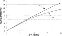
また、前記負極活物質と炭素系活物質との混合物を含む負極電極と対極リチウムとから成る試験セルを作製し、該試験セルにおいて、前記負極活物質にリチウムを挿入するよう電流を流す充電と、前記負極活物質からリチウムを脱離するよう電流を流す放電とから成る充放電を30回実施し、各充放電における放電容量Qを前記対極リチウムを基準とする前記負極電極の電位Vで微分した微分値dQ/dVと前記電位Vとの関係を示すグラフを描いた場合に、X回目以降(1≦X≦30)の放電時における、前記負極電極の電位Vが0.40V〜0.55Vの範囲にピークを有するものであることが好ましい。 In addition, a test cell comprising a negative electrode containing a mixture of the negative electrode active material and the carbon-based active material and counter lithium is prepared, and in the test cell, charging is performed such that current is inserted so that lithium is inserted into the negative electrode active material. 30 times of charge / discharge consisting of discharge through which current flows so as to desorb lithium from the negative electrode active material, and the discharge capacity Q in each charge / discharge is differentiated by the potential V of the negative electrode with respect to the counter lithium. When the graph showing the relationship between the differentiated differential value dQ / dV and the potential V is drawn, the potential V of the negative electrode during the Xth and subsequent discharges (1 ≦ X ≦ 30) is 0.40 V to. It is preferable to have a peak in the range of 55V.
V−dQ/dV曲線における上記のピークはケイ素材のピークと類似しており、より高電位側における放電カーブが鋭く立ち上がるため、電池設計を行う際、容量発現しやすくなる。また、上記ピークが30回以内の充放電で発現するものであれば、安定したバルクが形成される負極活物質となる。 The above peak in the V-dQ / dV curve is similar to the peak of the siliceous material, and the discharge curve on the higher potential side rises sharply, so that the capacity is easily developed when designing the battery. Moreover, if the said peak expresses by charge / discharge within 30 times, it will become a negative electrode active material in which a stable bulk is formed.
また、前記負極活物質粒子はメジアン径が1.0μm以上15μm以下であることが好ましい。 The negative electrode active material particles preferably have a median diameter of 1.0 μm to 15 μm.
メジアン径が1.0μm以上であれば、質量当たりの表面積の増加により電池不可逆容量が増加することを抑制することができる。一方で、メジアン径を15μm以下とすることで、粒子が割れ難くなるため新表面が出難くなる。 If the median diameter is 1.0 μm or more, an increase in battery irreversible capacity due to an increase in surface area per mass can be suppressed. On the other hand, when the median diameter is set to 15 μm or less, the particles are difficult to break and a new surface is difficult to appear.
また、前記負極活物質粒子は、表層部に炭素材を含むことが好ましい。 Moreover, it is preferable that the negative electrode active material particles include a carbon material in a surface layer portion.
このように、負極活物質粒子がその表層部に炭素材を含むことで、導電性の向上が得られる。 Thus, electroconductivity improvement is acquired because the negative electrode active material particle contains a carbon material in the surface layer part.
また、前記炭素材の平均厚さは10nm以上5000nm以下であることが好ましい。 The average thickness of the carbon material is preferably 10 nm or more and 5000 nm or less.
炭素材の平均厚さが10nm以上であれば導電性向上が得られる。また、被覆する炭素材の平均厚さが5000nm以下であれば、このような負極活物質粒子を含む負極活物質をリチウムイオン二次電池に用いることにより、ケイ素化合物粒子を十分な量確保できるので、電池容量の低下を抑制することができる。 If the average thickness of the carbon material is 10 nm or more, conductivity can be improved. Moreover, if the average thickness of the carbon material to be coated is 5000 nm or less, a sufficient amount of silicon compound particles can be secured by using a negative electrode active material including such negative electrode active material particles in a lithium ion secondary battery. , Battery capacity reduction can be suppressed.
上記の負極活物質と炭素系活物質とを含むことを特徴とする混合負極活物質材料を提供する。 Provided is a mixed negative electrode active material comprising the negative electrode active material and a carbon-based active material.
このように、負極活物質層を形成する材料として、本発明の負極活物質(ケイ素系負極活物質)とともに炭素系活物質を含むことで、負極活物質層の導電性を向上させることができるとともに、充電に伴う膨張応力を緩和することが可能となる。また、ケイ素系負極活物質を炭素系活物質に混合することで電池容量を増加させることができる。 Thus, as a material for forming the negative electrode active material layer, the conductivity of the negative electrode active material layer can be improved by including the carbon-based active material together with the negative electrode active material (silicon-based negative electrode active material) of the present invention. At the same time, the expansion stress associated with charging can be relaxed. Further, the battery capacity can be increased by mixing the silicon-based negative electrode active material with the carbon-based active material.
また、上記目的を達成するために、本発明は、上記の混合負極活物質材料を含み、前記負極活物質と前記炭素系活物質の質量の合計に対する、前記負極活物質の質量の割合が6質量%以上であることを特徴とする非水電解質二次電池用負極を提供する。 In order to achieve the above object, the present invention includes the above mixed negative electrode active material, and the ratio of the mass of the negative electrode active material to the total mass of the negative electrode active material and the carbon-based active material is 6 Provided is a negative electrode for a non-aqueous electrolyte secondary battery, characterized by being at least mass%.
上記の負極活物質(ケイ素系負極活物質)と炭素系活物質の質量の合計に対する、負極活物質(ケイ素系負極活物質)の質量の割合が6質量%以上であれば、電池容量をより向上させることが可能となる。 If the ratio of the mass of the negative electrode active material (silicon-based negative electrode active material) to the total mass of the negative electrode active material (silicon-based negative electrode active material) and the carbon-based active material is 6% by mass or more, the battery capacity is further increased. It becomes possible to improve.
また、上記目的を達成するために、本発明は、上記の混合負極活物質材料で形成された負極活物質層と、負極集電体とを有し、前記負極活物質層は前記負極集電体上に形成されており、前記負極集電体は炭素及び硫黄を含むとともに、それらの含有量がいずれも100質量ppm以下であることを特徴とする非水電解質二次電池用負極を提供する。 In order to achieve the above object, the present invention includes a negative electrode active material layer formed of the above mixed negative electrode active material and a negative electrode current collector, and the negative electrode active material layer includes the negative electrode current collector. Provided is a negative electrode for a non-aqueous electrolyte secondary battery, wherein the negative electrode current collector contains carbon and sulfur, and the content thereof is 100 ppm by mass or less. .
このように、負極電極を構成する負極集電体が、炭素及び硫黄を上記のような量で含むことで、充電時の負極電極の変形を抑制することができる。 As described above, the negative electrode current collector constituting the negative electrode includes carbon and sulfur in the above amounts, whereby deformation of the negative electrode during charging can be suppressed.
また、上記目的を達成するために、本発明は、上記の負極活物質を含む負極を用いたものであることを特徴とするリチウムイオン二次電池を提供する。 Moreover, in order to achieve the said objective, this invention provides the lithium ion secondary battery characterized by using the negative electrode containing said negative electrode active material.
このような負極活物質を含む負極を用いたリチウムイオン二次電池であれば、高容量であるとともに良好なサイクル特性及び初期充放電特性が得られる。 If it is a lithium ion secondary battery using the negative electrode containing such a negative electrode active material, while being high capacity | capacitance, favorable cycling characteristics and initial stage charge / discharge characteristics will be obtained.
また、上記目的を達成するために、本発明は、ケイ素化合物粒子を含有する負極活物質粒子を含む負極活物質を製造する方法であって、ケイ素化合物(SiOx:0.5≦x≦1.6)及びニッケルを含むケイ素化合物粒子を含有する負極活物質粒子を作製する工程と、前記負極活物質粒子にLiを挿入し、Li2SiO3、Li4SiO4のうち少なくとも1種以上を含有させる工程と、前記負極活物質粒子から、前記負極活物質粒子の質量に対する前記ニッケルの質量が2質量ppm以上100質量ppm以下のものを選別する工程とを含み、該選別した前記負極活物質粒子を用いて、負極活物質を製造することを特徴とする負極活物質の製造方法を提供する。 In order to achieve the above object, the present invention provides a method for producing a negative electrode active material including negative electrode active material particles containing silicon compound particles, wherein the silicon compound (SiO x : 0.5 ≦ x ≦ 1). .6) and a step of producing negative electrode active material particles containing nickel-containing silicon compound particles, and inserting Li into the negative electrode active material particles, and at least one of Li 2 SiO 3 and Li 4 SiO 4 Including the step of containing, and the step of selecting, from the negative electrode active material particles, one having a mass of the nickel of 2 mass ppm to 100 mass ppm with respect to the mass of the negative electrode active material particles. Provided is a method for producing a negative electrode active material, characterized in that a negative electrode active material is produced using particles.
ケイ素系活物質粒子をこのように選別して、負極活物質を製造することで、リチウムイオン二次電池の負極活物質として使用した際に高容量であるとともに良好なサイクル特性及び初期充放電特性を有する負極活物質を製造することができる。 By selecting the silicon-based active material particles in this way to produce the negative electrode active material, the high capacity and good cycle characteristics and initial charge / discharge characteristics when used as the negative electrode active material of a lithium ion secondary battery The negative electrode active material which has can be manufactured.
また、上記目的を達成するために、本発明は、上記の負極活物質の製造方法によって製造した負極活物質を用いて負極を作製し、該作製した負極を用いてリチウムイオン二次電池を製造することを特徴とするリチウムイオン二次電池の製造方法を提供する。 In order to achieve the above object, the present invention produces a negative electrode using the negative electrode active material produced by the method for producing a negative electrode active material, and produces a lithium ion secondary battery using the produced negative electrode. A method for manufacturing a lithium ion secondary battery is provided.
上記のように製造された負極活物質を用いることにより、高容量であるとともに良好なサイクル特性及び初期充放電特性を有するリチウムイオン二次電池を製造することができる。 By using the negative electrode active material manufactured as described above, it is possible to manufacture a lithium ion secondary battery having high capacity and good cycle characteristics and initial charge / discharge characteristics.
本発明の負極活物質は、二次電池の負極活物質として用いた際に、高容量で良好なサイクル特性及び初期充放電特性が得られる。また、この負極活物質を含む混合負極活物質材料、負極、及びリチウムイオン二次電池においても同様の効果が得られる。また、本発明の負極活物質の製造方法であれば、二次電池の負極活物質として用いた際に、良好なサイクル特性及び初期充放電特性を有する負極活物質を製造することができる。 When the negative electrode active material of the present invention is used as a negative electrode active material for a secondary battery, high capacity and good cycle characteristics and initial charge / discharge characteristics can be obtained. Moreover, the same effect is acquired also in the mixed negative electrode active material material containing this negative electrode active material, a negative electrode, and a lithium ion secondary battery. Moreover, if it is a manufacturing method of the negative electrode active material of this invention, when it uses as a negative electrode active material of a secondary battery, the negative electrode active material which has a favorable cycling characteristic and an initial stage charge / discharge characteristic can be manufactured.
以下、本発明について実施の形態を説明するが、本発明はこれに限定されるものではない。 Hereinafter, although an embodiment is described about the present invention, the present invention is not limited to this.
前述のように、リチウムイオン二次電池の電池容量を増加させる1つの手法として、ケイ素材を主材として用いた負極をリチウムイオン二次電池の負極として用いることが検討されている。このケイ素材を用いたリチウムイオン二次電池は、炭素系活物質を用いたリチウムイオン二次電池と同等に近い初期充放電特性及びサイクル特性が望まれているが、炭素系活物質を用いたリチウムイオン二次電池と同等の初期充放電特性及びサイクル特性を有する負極活物質を提案するには至っていなかった。 As described above, as one method for increasing the battery capacity of a lithium ion secondary battery, the use of a negative electrode using a silicon material as a main material as a negative electrode of a lithium ion secondary battery has been studied. The lithium ion secondary battery using this siliceous material is desired to have initial charge / discharge characteristics and cycle characteristics similar to those of a lithium ion secondary battery using a carbon-based active material, but the carbon-based active material is used. A negative electrode active material having initial charge / discharge characteristics and cycle characteristics equivalent to those of a lithium ion secondary battery has not been proposed.
そこで、本発明者はこのような問題を解決すべく鋭意検討を重ねた。その結果、負極活物質粒子は、ケイ素化合物(SiOx:0.5≦x≦1.6)を含むケイ素化合物粒子を含有し、ケイ素化合物粒子は、Li2SiO3及びLi4SiO4のうち少なくとも1種以上を含有し、ケイ素化合物粒子はニッケルを含有し、負極活物質粒子の質量に対するニッケルの質量が2質量ppm以上100質量ppm以下という関係を満たす負極活物質であれば、二次電池に用いた際に、良好なサイクル特性及び初期充放電特性が得られることを見出し、本発明をなすに至った。 Therefore, the present inventor has intensively studied to solve such problems. As a result, the negative electrode active material particles contain silicon compound particles containing a silicon compound (SiO x : 0.5 ≦ x ≦ 1.6), and the silicon compound particles are Li 2 SiO 3 and Li 4 SiO 4 . If the negative electrode active material contains at least one kind, the silicon compound particles contain nickel, and the mass of nickel relative to the mass of the negative electrode active material particles satisfies the relationship of 2 mass ppm to 100 mass ppm, the secondary battery As a result, the present inventors have found that good cycle characteristics and initial charge / discharge characteristics can be obtained.
<非水電解質二次電池用負極>
まず、非水電解質二次電池用負極について説明する。図1は本発明の一実施形態における非水電解質二次電池用負極(以下、「負極」とも呼称する)の断面構成を表している。
<Negative electrode for non-aqueous electrolyte secondary battery>
First, the negative electrode for nonaqueous electrolyte secondary batteries will be described. FIG. 1 shows a cross-sectional configuration of a negative electrode for a nonaqueous electrolyte secondary battery (hereinafter also referred to as “negative electrode”) according to an embodiment of the present invention.
[負極の構成]
図1に示したように、負極10は、負極集電体11の上に負極活物質層12を有する構成になっている。この負極活物質層12は負極集電体11の両面、又は、片面だけに設けられていても良い。さらに、本発明の負極活物質が用いられたものであれば、負極集電体11はなくてもよい。
[Configuration of negative electrode]
As shown in FIG. 1, the
[負極集電体]
負極集電体11は、優れた導電性材料であり、かつ、機械的な強度に長けた物で構成される。負極集電体11に用いることができる導電性材料として、例えば銅(Cu)やニッケル(Ni)があげられる。この導電性材料は、リチウム(Li)と金属間化合物を形成しない材料であることが好ましい。
[Negative electrode current collector]
The negative electrode current collector 11 is an excellent conductive material and is made of a material that is excellent in mechanical strength. Examples of the conductive material that can be used for the negative electrode current collector 11 include copper (Cu) and nickel (Ni). This conductive material is preferably a material that does not form an intermetallic compound with lithium (Li).
負極集電体11は、主元素以外に炭素(C)や硫黄(S)を含んでいることが好ましい。負極集電体の物理的強度が向上するためである。特に、充電時に膨張する活物質層を有する場合、集電体が上記の元素を含んでいれば、集電体を含む電極変形を抑制する効果があるからである。上記の含有元素の含有量は、特に限定されないが、中でも、それぞれ100質量ppm以下であることが好ましい。より高い変形抑制効果が得られるからである。このような変形抑制効果によりサイクル特性をより向上できる。 The negative electrode current collector 11 preferably contains carbon (C) or sulfur (S) in addition to the main element. This is because the physical strength of the negative electrode current collector is improved. In particular, in the case of having an active material layer that expands during charging, if the current collector contains the above-described element, there is an effect of suppressing electrode deformation including the current collector. Although content of said content element is not specifically limited, Especially, it is preferable that it is 100 mass ppm or less, respectively. This is because a higher deformation suppressing effect can be obtained. Such a deformation suppressing effect can further improve the cycle characteristics.
また、負極集電体11の表面は粗化されていてもよいし、粗化されていなくてもよい。粗化されている負極集電体は、例えば、電解処理、エンボス処理、又は、化学エッチング処理された金属箔などである。粗化されていない負極集電体は、例えば、圧延金属箔などである。 Further, the surface of the negative electrode current collector 11 may be roughened or may not be roughened. The roughened negative electrode current collector is, for example, a metal foil subjected to electrolytic treatment, embossing treatment, or chemical etching treatment. The non-roughened negative electrode current collector is, for example, a rolled metal foil.
[負極活物質層]
負極活物質層12は、リチウムイオンを吸蔵、放出可能な本発明の負極活物質を含んでおり、電池設計上の観点から、さらに、負極結着剤(バインダ)や導電助剤など他の材料を含んでいてもよい。負極活物質は負極活物質粒子を含み、負極活物質粒子はケイ素化合物(SiOx:0.5≦x≦1.6)を含有するケイ素化合物粒子を含む。
[Negative electrode active material layer]
The negative electrode
また、負極活物質層12は、本発明の負極活物質と炭素系活物質とを含む混合負極活物質材料を含んでいても良い。これにより、負極活物質層の電気抵抗が低下するとともに、充電に伴う膨張応力を緩和することが可能となる。炭素系活物質としては、例えば、熱分解炭素類、コークス類、ガラス状炭素繊維、有機高分子化合物焼成体、カーボンブラック類などを使用できる。
The negative electrode
また、本発明の負極は、本発明の負極活物質(ケイ素系負極活物質)と炭素系活物質の質量の合計に対する、負極活物質(ケイ素系負極活物質)の質量の割合が6質量%以上であることが好ましい。本発明の負極活物質と炭素系活物質の質量の合計に対する、本発明の負極活物質の質量の割合が6質量%以上であれば、電池容量を確実に向上させることが可能となる。 In the negative electrode of the present invention, the ratio of the mass of the negative electrode active material (silicon-based negative electrode active material) to the total mass of the negative electrode active material (silicon-based negative electrode active material) of the present invention and the carbon-based active material is 6% by mass. The above is preferable. If the ratio of the mass of the negative electrode active material of the present invention to the total mass of the negative electrode active material and the carbon-based active material of the present invention is 6% by mass or more, the battery capacity can be reliably improved.
また、上記のように本発明の負極活物質は、ケイ素化合物粒子を含み、ケイ素化合物粒子はケイ素化合物(SiOx:0.5≦x≦1.6)を含有する酸化ケイ素材であるが、その組成はxが1に近い方が好ましい。なぜならば、高いサイクル特性が得られるからである。なお、本発明におけるケイ素化合物の組成は必ずしも純度100%を意味しているわけではなく、微量の不純物元素を含んでいてもよい。 Further, as described above, the negative electrode active material of the present invention contains silicon compound particles, and the silicon compound particles are a silicon oxide material containing a silicon compound (SiO x : 0.5 ≦ x ≦ 1.6). The composition is preferably such that x is close to 1. This is because high cycle characteristics can be obtained. Note that the composition of the silicon compound in the present invention does not necessarily mean a purity of 100%, and may contain a trace amount of impurity elements.
また、本発明の負極活物質において、ケイ素化合物粒子は、Li2SiO3及びLi4SiO4のうち少なくとも1種以上を含有している。このようなものは、ケイ素化合物中の、電池の充放電時のリチウムの挿入、脱離時に不安定化するSiO2成分部を予め別のリチウムシリケートに改質させたものであるので、充電時に発生する不可逆容量を低減することができる。 In the negative electrode active material of the present invention, the silicon compound particles contain at least one of Li 2 SiO 3 and Li 4 SiO 4 . In such a case, in the silicon compound, the SiO 2 component part, which is destabilized at the time of charging / discharging of the battery and destabilized at the time of charging / discharging, is modified in advance to another lithium silicate. The generated irreversible capacity can be reduced.
また、ケイ素化合物粒子のバルク内部にLi4SiO4、Li2SiO3は少なくとも1種以上存在することで電池特性が向上するが、上記2種類のLi化合物を共存させる場合に電池特性がより向上する。なお、これらのリチウムシリケートは、NMR(Nuclear Magnetic Resonance:核磁気共鳴)又はXPS(X−ray photoelectron spectroscopy:X線光電子分光)で定量可能である。XPSとNMRの測定は、例えば、以下の条件により行うことができる。
XPS
・装置: X線光電子分光装置、
・X線源: 単色化Al Kα線、
・X線スポット径: 100μm、
・Arイオン銃スパッタ条件: 0.5kV/2mm×2mm。
29Si MAS NMR(マジック角回転核磁気共鳴)
・装置: Bruker社製700NMR分光器、
・プローブ: 4mmHR−MASローター 50μL、
・試料回転速度: 10kHz、
・測定環境温度: 25℃。
In addition, the battery characteristics are improved when at least one of Li 4 SiO 4 and Li 2 SiO 3 is present in the bulk of the silicon compound particles, but the battery characteristics are further improved when the two types of Li compounds are present together. To do. Note that these lithium silicates can be quantified by NMR (Nuclear Magnetic Resonance) or XPS (X-ray photoelectron spectroscopy: X-ray photoelectron spectroscopy). The XPS and NMR measurements can be performed, for example, under the following conditions.
XPS
・ Device: X-ray photoelectron spectrometer,
・ X-ray source: Monochromatic Al Kα ray,
・ X-ray spot diameter: 100 μm,
Ar ion gun sputtering conditions: 0.5 kV / 2 mm × 2 mm.
29 Si MAS NMR (magic angle rotating nuclear magnetic resonance)
Apparatus: 700 NMR spectrometer manufactured by Bruker,
Probe: 4 mm HR-MAS rotor 50 μL,
Sample rotation speed: 10 kHz,
-Measurement environment temperature: 25 ° C.
さらに、ケイ素化合物粒子はニッケルを含有し、負極活物質粒子の質量に対するニッケルの質量が2質量ppm以上100質量ppm以下である。ケイ素化合物粒子がこのような割合でニッケルを含むことで、負極活物質の電子伝導性が向上する。負極活物質粒子の質量に対するニッケルの質量が2質量ppm未満であると、電子伝導性の向上効果が十分に得られない。負極活物質粒子の質量に対するニッケルの質量が、100質量ppmより大きいと、ケイ素化合物の構造変化によりリチウム拡散性が低下し、サイクル特性及び容量維持率の低下を招いてしまう。 Furthermore, the silicon compound particles contain nickel, and the mass of nickel with respect to the mass of the negative electrode active material particles is 2 mass ppm or more and 100 mass ppm or less. When the silicon compound particles contain nickel in such a ratio, the electronic conductivity of the negative electrode active material is improved. When the mass of nickel with respect to the mass of the negative electrode active material particles is less than 2 mass ppm, the effect of improving the electronic conductivity cannot be sufficiently obtained. When the mass of nickel with respect to the mass of the negative electrode active material particles is larger than 100 mass ppm, the lithium diffusibility is lowered due to the structural change of the silicon compound, and the cycle characteristics and the capacity retention rate are lowered.
また、ケイ素化合物粒子が、さらにクロムを含有することが好ましく、負極活物質粒子の質量に対するニッケルの質量及びクロムの質量の和が2質量ppm以上100質量ppm以下であることが好ましい。ケイ素化合物粒子がこのような割合でニッケル及びクロムを含むことで、負極活物質の電子伝導性がより向上する。上記の和が2質量ppm以上であれば、電子伝導性が効果的に向上し、上記の和が100質量ppm以下であれば、ケイ素化合物の構造変化を抑制できる。その結果、二次電池に用いた際に、初期充放電特性及びサイクル特性をより向上させることが可能な負極活物質となる。 Moreover, it is preferable that a silicon compound particle contains chromium further, and it is preferable that the sum of the mass of nickel with respect to the mass of negative electrode active material particles and the mass of chromium is 2 mass ppm or more and 100 mass ppm or less. When the silicon compound particles contain nickel and chromium in such a ratio, the electronic conductivity of the negative electrode active material is further improved. If said sum is 2 mass ppm or more, electronic conductivity will improve effectively, and if said sum is 100 mass ppm or less, the structural change of a silicon compound can be suppressed. As a result, when used in a secondary battery, it becomes a negative electrode active material capable of further improving initial charge / discharge characteristics and cycle characteristics.
また、ケイ素化合物粒子が、さらにアルミニウムを含有することが好ましく、負極活物質粒子の質量に対するアルミニウムの質量が5質量ppm以上500質量ppm以下であることが好ましい。ケイ素化合物粒子がこのような割合で、さらにアルミニウムを含むことで、負極活物質の電子伝導性がより向上する。負極活物質粒子の質量に対するアルミニウムの質量が5質量ppm以上であれば、電子伝導性が効果的に向上し、負極活物質粒子の質量に対するアルミニウムの質量が500質量ppm以下であれば、ケイ素化合物の構造変化を抑制できる。その結果、二次電池に用いた際に、サイクル特性をより向上させることが可能な負極活物質となる。 Moreover, it is preferable that a silicon compound particle contains aluminum further, and it is preferable that the mass of aluminum with respect to the mass of negative electrode active material particles is 5 mass ppm or more and 500 mass ppm or less. When the silicon compound particles contain aluminum in such a ratio, the electronic conductivity of the negative electrode active material is further improved. If the mass of aluminum relative to the mass of the negative electrode active material particles is 5 mass ppm or more, the electron conductivity is effectively improved, and if the mass of aluminum relative to the mass of the negative electrode active material particles is 500 mass ppm or less, a silicon compound The structural change of can be suppressed. As a result, when used in a secondary battery, it becomes a negative electrode active material capable of further improving cycle characteristics.
また、本発明の負極活物質は、ケイ素化合物粒子の少なくとも一部に、アルミニウム−リチウム合金を含有することが好ましい。これにより、負極の製造時に、負極活物質粒子を混合したスラリー中へのリチウムの溶出を抑制することができ、スラリーを安定化できる。 The negative electrode active material of the present invention preferably contains an aluminum-lithium alloy in at least a part of the silicon compound particles. Thereby, at the time of manufacture of a negative electrode, the elution of lithium into the slurry mixed with the negative electrode active material particles can be suppressed, and the slurry can be stabilized.
また、ケイ素化合物粒子が、さらにジルコニウムを含有することが好ましく、負極活物質粒子の質量に対するジルコニウムの質量が0.5質量ppm以上500質量ppm以下であることが好ましい。特に、負極活物質粒子の質量に対するジルコニウムの質量が10質量ppm以上100質量ppm以下であることがより好ましい。ケイ素化合物粒子がこのような割合で、さらにジルコニウムを含むことで、電池の充放電時のケイ素化合物粒子の膨張、収縮による応力を緩和することができる。負極活物質粒子の質量に対するジルコニウムの質量が0.5質量ppm以上であれば、応力の緩和効果を十分に得られる。また、負極活物質粒子の質量に対するジルコニウムの質量が500質量ppm以下であれば、ケイ素化合物の構造変化を抑制できる。その結果、二次電池に用いた際に、サイクル特性をより向上させることが可能な負極活物質となる。 Moreover, it is preferable that a silicon compound particle contains a zirconium further, and it is preferable that the mass of the zirconium with respect to the mass of a negative electrode active material particle is 0.5 mass ppm or more and 500 mass ppm or less. In particular, the mass of zirconium with respect to the mass of the negative electrode active material particles is more preferably 10 ppm by mass or more and 100 ppm by mass or less. When the silicon compound particles further contain zirconium in such a ratio, stress due to expansion and contraction of the silicon compound particles during charge / discharge of the battery can be relieved. If the mass of zirconium with respect to the mass of the negative electrode active material particles is 0.5 ppm by mass or more, a stress relaxation effect can be sufficiently obtained. Moreover, if the mass of zirconium with respect to the mass of the negative electrode active material particles is 500 mass ppm or less, the structural change of the silicon compound can be suppressed. As a result, when used in a secondary battery, it becomes a negative electrode active material capable of further improving cycle characteristics.
また、ニッケル、クロム、アルミニウム、及びジルコニウムをケイ素系活物質粒子に含ませるためには、後述のようにケイ素化合物を製造する際の原料にニッケル、クロム、アルミニウム、及びジルコニウムを含む物質を添加すればよい。例えば、酸化珪素ガスを発生させる原料を加熱し、発生した酸化珪素ガスを吸着板上に堆積させることでケイ素化合物粒子を得る場合、上記の金属成分を添加した原料を用いることで、酸化珪素ガスと共にニッケル、クロム、アルミニウム、ジルコニウムが蒸発し、ケイ素化合物粒子に混入する。 In addition, in order to include nickel, chromium, aluminum, and zirconium in the silicon-based active material particles, a material containing nickel, chromium, aluminum, and zirconium is added to the raw material for producing the silicon compound as described later. That's fine. For example, when silicon compound particles are obtained by heating a raw material that generates silicon oxide gas and depositing the generated silicon oxide gas on an adsorption plate, the silicon oxide gas is obtained by using the raw material to which the above metal component is added. At the same time, nickel, chromium, aluminum and zirconium are evaporated and mixed into the silicon compound particles.
ケイ素化合物粒子に含まれる金属元素の元素量は、例えば、ICP−OES(高周波誘導結合プラズマ発光分光質量分析法)などにより測定することができる。 The element amount of the metal element contained in the silicon compound particles can be measured by, for example, ICP-OES (High Frequency Inductively Coupled Plasma Emission Spectroscopy Mass Spectrometry).
また、ケイ素化合物粒子は、X線回折により得られるSi(111)結晶面に起因する回折ピークの半値幅(2θ)が1.2°以上であるとともに、その結晶面に対応する結晶子サイズは7.5nm以下であることが好ましい。ケイ素化合物粒子におけるケイ素化合物のケイ素結晶性は低いほどよく、特に、Si結晶の存在量が少なければ、電池特性を向上でき、さらに、安定的なLi化合物が生成できる。 In addition, the silicon compound particles have a half-value width (2θ) of a diffraction peak due to the Si (111) crystal plane obtained by X-ray diffraction of 1.2 ° or more, and the crystallite size corresponding to the crystal plane is It is preferable that it is 7.5 nm or less. The silicon crystallinity of the silicon compound in the silicon compound particles is preferably as low as possible. In particular, if the amount of Si crystal is small, battery characteristics can be improved, and a stable Li compound can be generated.
また、本発明の負極活物質は、ケイ素化合物粒子において、29Si−MAS−NMRスペクトルから得られる、ケミカルシフト値として−60〜−95ppmで与えられるSi及びLiシリケート領域の最大ピーク強度値Aと、ケミカルシフト値として−96〜−150ppmで与えられるSiO2領域のピーク強度値Bが、A>Bという関係を満たすことが好ましい。ケイ素化合物粒子において、SiO2成分を基準とした場合にケイ素成分又はLi2SiO3の量が比較的多いものであれば、Liの挿入による電池特性の向上効果を十分に得られる。 Further, the negative electrode active material of the present invention is obtained from the 29 Si-MAS-NMR spectrum in the silicon compound particles, and has a maximum peak intensity value A in the Si and Li silicate regions given by −60 to −95 ppm as a chemical shift value. It is preferable that the peak intensity value B in the SiO 2 region given by −96 to −150 ppm as the chemical shift value satisfies the relationship of A> B. If the silicon compound particles have a relatively large amount of silicon component or Li 2 SiO 3 when the SiO 2 component is used as a reference, the effect of improving battery characteristics due to insertion of Li can be sufficiently obtained.
本発明の負極活物質は、該負極活物質と炭素系活物質との混合物を含む負極電極と対極リチウムとから成る試験セルを作製し、該試験セルにおいて、負極活物質にリチウムを挿入するよう電流を流す充電と、負極活物質からリチウムを脱離するよう電流を流す放電とから成る充放電を30回実施し、各充放電における放電容量Qを前記対極リチウムを基準とする負極電極の電位Vで微分した微分値dQ/dVと電位Vとの関係を示すグラフを描いた場合に、X回目以降(1≦X≦30)の放電時における、負極電極の電位Vが0.40V〜0.55Vの範囲にピークを有するものであることが好ましい。V−dQ/dV曲線における上記のピークはケイ素材のピークと類似しており、より高電位側における放電カーブが鋭く立ち上がるため、電池設計を行う際、容量発現しやすくなる。また、上記ピークが30回以内の充放電で発現するものであれば、安定したバルクが形成されるものであると判断できる。 The negative electrode active material of the present invention is prepared by preparing a test cell composed of a negative electrode containing a mixture of the negative electrode active material and a carbon-based active material and counter lithium, and inserting lithium into the negative electrode active material in the test cell. Charging / discharging comprising charging for flowing current and discharging for flowing current so as to desorb lithium from the negative electrode active material is performed 30 times, and the discharge capacity Q in each charge / discharge is the potential of the negative electrode with respect to the counter lithium. When a graph showing the relationship between the differential value dQ / dV differentiated by V and the potential V is drawn, the potential V of the negative electrode is 0.40 V to 0 at the time of discharge after the Xth (1 ≦ X ≦ 30). It is preferable to have a peak in the range of .55V. The above peak in the V-dQ / dV curve is similar to the peak of the siliceous material, and the discharge curve on the higher potential side rises sharply, so that the capacity is easily developed when designing the battery. Moreover, if the said peak expresses by charging / discharging within 30 times, it can be judged that the stable bulk is formed.
また、本発明の負極活物質は、負極活物質粒子のメジアン径(D50:累積体積が50%となる時の粒子径)が1.0μm以上15μm以下であることが好ましい。メジアン径が上記の範囲であれば、充放電時においてリチウムイオンの吸蔵放出がされやすくなるとともに、粒子が割れにくくなるからである。メジアン径が1.0μm以上であれば、質量当たりの表面積を小さくでき、電池不可逆容量の増加を抑制することができる。一方で、メジアン径を15μm以下とすることで、粒子が割れ難くなるため新表面が出難くなる。 In the negative electrode active material of the present invention, the negative electrode active material particles preferably have a median diameter (D 50 : particle diameter at a cumulative volume of 50%) of 1.0 μm or more and 15 μm or less. This is because, if the median diameter is in the above range, lithium ions are easily occluded and released during charging and discharging, and the particles are difficult to break. When the median diameter is 1.0 μm or more, the surface area per mass can be reduced, and an increase in battery irreversible capacity can be suppressed. On the other hand, when the median diameter is set to 15 μm or less, the particles are difficult to break and a new surface is difficult to appear.
また、本発明の負極活物質において、負極活物質粒子は、表層部に炭素材を含むことが好ましい。負極活物質粒子がその表層部に炭素材を含むことで、導電性の向上が得られるため、このような負極活物質粒子を含む負極活物質を二次電池の負極活物質として用いた際に、電池特性を向上させることができる。 In the negative electrode active material of the present invention, the negative electrode active material particles preferably include a carbon material in the surface layer portion. When the negative electrode active material particles include a carbon material in the surface layer portion, the conductivity can be improved. Therefore, when the negative electrode active material containing such negative electrode active material particles is used as the negative electrode active material of a secondary battery. Battery characteristics can be improved.
また、負極活物質粒子の表層部の炭素材の平均厚さは、10nm以上5000nm以下であることが好ましい。炭素材の平均厚さが10nm以上であれば導電性向上が得られ、被覆する炭素材の平均厚さが5000nm以下であれば、このような負極活物質粒子を含む負極活物質をリチウムイオン二次電池の負極活物質として用いた際に、電池容量の低下を抑制することができる。 Moreover, it is preferable that the average thickness of the carbon material of the surface layer part of negative electrode active material particles is 10 nm or more and 5000 nm or less. If the average thickness of the carbon material is 10 nm or more, conductivity can be improved, and if the average thickness of the carbon material to be coated is 5000 nm or less, the negative electrode active material containing such negative electrode active material particles is converted into lithium ion When used as a negative electrode active material for a secondary battery, a decrease in battery capacity can be suppressed.
この被覆炭素部の平均厚さは、例えば、以下の手順により算出できる。先ず、TEM(透過型電子顕微鏡)により任意の倍率で負極活物質粒子を観察する。この倍率は、厚さを測定できるように、目視で被覆部の厚さを確認できる倍率が好ましい。続いて、任意の15点において、被覆部の厚さを測定する。この場合、できるだけ特定の場所に集中せず、広くランダムに測定位置を設定することが好ましい。最後に、上記の15点の被覆部の厚さの平均値を算出する。 The average thickness of the coated carbon part can be calculated by the following procedure, for example. First, negative electrode active material particles are observed at an arbitrary magnification using a TEM (transmission electron microscope). This magnification is preferably a magnification by which the thickness of the covering portion can be visually confirmed so that the thickness can be measured. Subsequently, the thickness of the covering portion is measured at any 15 points. In this case, it is preferable to set the measurement position widely and randomly without concentrating on a specific place as much as possible. Finally, the average value of the thicknesses of the 15 covering portions is calculated.
炭素材の被覆率は特に限定されないが、できるだけ高い方が望ましい。被覆率が30%以上であれば、電気伝導性がより向上するため好ましい。炭素材の被覆手法は特に限定されないが、糖炭化法、炭化水素ガスの熱分解法が好ましい。なぜならば、被覆率を向上させることができるからである。 The coverage of the carbon material is not particularly limited, but is preferably as high as possible. A coverage of 30% or more is preferable because electric conductivity is further improved. The method for coating the carbon material is not particularly limited, but a sugar carbonization method and a pyrolysis method of hydrocarbon gas are preferable. This is because the coverage can be improved.
また、負極活物質層に含まれる負極結着剤としては、例えば、高分子材料、合成ゴムなどのいずれか1種類以上を用いることができる。高分子材料は、例えば、ポリフッ化ビニリデン、ポリイミド、ポリアミドイミド、アラミド、ポリアクリル酸、ポリアクリル酸リチウム、カルボキシメチルセルロースなどである。合成ゴムは、例えば、スチレンブタジエン系ゴム、フッ素系ゴム、エチレンプロピレンジエンなどである。 Moreover, as a negative electrode binder contained in a negative electrode active material layer, any one or more types, such as a polymeric material and a synthetic rubber, can be used, for example. Examples of the polymer material include polyvinylidene fluoride, polyimide, polyamideimide, aramid, polyacrylic acid, lithium polyacrylate, and carboxymethylcellulose. Examples of the synthetic rubber include styrene butadiene rubber, fluorine rubber, and ethylene propylene diene.
負極導電助剤としては、例えば、カーボンブラック、アセチレンブラック、黒鉛、ケチェンブラック、カーボンナノチューブ、カーボンナノファイバーなどの炭素材料のいずれか1種以上を用いることができる。 As a negative electrode conductive support agent, any 1 or more types of carbon materials, such as carbon black, acetylene black, graphite, ketjen black, a carbon nanotube, carbon nanofiber, can be used, for example.
負極活物質層は、例えば、塗布法で形成される。塗布法とは、負極活物質粒子と上記の結着剤など、また、必要に応じて導電助剤、炭素材料を混合した後に、有機溶剤や水などに分散させ塗布する方法である。 The negative electrode active material layer is formed by, for example, a coating method. The coating method is a method in which negative electrode active material particles and the above-mentioned binder, and the like, and a conductive additive and a carbon material are mixed as necessary, and then dispersed and applied in an organic solvent or water.
[負極の製造方法]
負極は、例えば、以下の手順により製造できる。まず、負極に使用する負極活物質の製造方法を説明する。最初に、ケイ素化合物(SiOx:0.5≦x≦1.6)及びニッケルを含むケイ素化合物粒子を含有する負極活物質粒子を作製する。次に、負極活物質粒子にLiを挿入し、Li2SiO3、Li4SiO4のうち少なくとも1種以上を含有させる。次に、負極活物質粒子から、負極活物質粒子の質量に対するニッケルの質量が2質量ppm以上100質量ppm以下のものを選別する。そして、選別した負極活物質粒子を用いて、負極活物質を製造する。
[Production method of negative electrode]
The negative electrode can be produced, for example, by the following procedure. First, the manufacturing method of the negative electrode active material used for a negative electrode is demonstrated. First, negative electrode active material particles containing silicon compound particles containing a silicon compound (SiO x : 0.5 ≦ x ≦ 1.6) and nickel are prepared. Next, Li is inserted into the negative electrode active material particles to contain at least one of Li 2 SiO 3 and Li 4 SiO 4 . Next, the negative electrode active material particles having a mass of nickel of 2 mass ppm to 100 mass ppm with respect to the mass of the negative electrode active material particles are selected. And the negative electrode active material is manufactured using the selected negative electrode active material particles.
より具体的には以下のように負極活物質を製造できる。先ず、酸化珪素ガスを発生する原料を不活性ガスの存在下、減圧下で900℃〜1600℃の温度範囲で加熱し、酸化珪素ガスを発生させる。このとき、原料は金属珪素粉末と二酸化珪素粉末とニッケルを含む物質との混合物を用いることができる。その他にも、クロム、アルミニウム、及びジルコニウムを含む物質を原料に添加しても良い。金属珪素粉末の表面酸素及び反応炉中の微量酸素の存在を考慮すると、混合モル比が、0.8<金属珪素粉末/二酸化珪素粉末<1.3の範囲であることが望ましい。 More specifically, the negative electrode active material can be produced as follows. First, a raw material that generates silicon oxide gas is heated in a temperature range of 900 ° C. to 1600 ° C. under reduced pressure in the presence of an inert gas to generate silicon oxide gas. At this time, the raw material can be a mixture of metal silicon powder, silicon dioxide powder and a substance containing nickel. In addition, a substance containing chromium, aluminum, and zirconium may be added to the raw material. Considering the surface oxygen of the metal silicon powder and the presence of a trace amount of oxygen in the reaction furnace, the mixing molar ratio is preferably in the range of 0.8 <metal silicon powder / silicon dioxide powder <1.3.
発生した酸化珪素ガスは吸着板上で固体化され堆積される。この際に、本発明では昇温速度や温度保持時間といった昇温プログラムを調整することで、負極活物質粒子の質量に対するニッケルの質量が2質量ppm以上100質量ppm以下となるように調整しても良い。次に、反応炉内温度を100℃以下に下げた状態で酸化珪素の堆積物を取出し、ボールミル、ジェットミルなどを用いて粉砕、粉末化を行う。以上のようにして、ニッケルを含むケイ素化合物粒子を作製することができる。なお、ケイ素化合物粒子中のSi結晶子は、気化温度の変更、又は、生成後の熱処理で制御できる。 The generated silicon oxide gas is solidified and deposited on the adsorption plate. At this time, in the present invention, by adjusting a temperature rising program such as a temperature rising rate and a temperature holding time, the mass of nickel with respect to the mass of the negative electrode active material particles is adjusted to be 2 mass ppm or more and 100 mass ppm or less. Also good. Next, a silicon oxide deposit is taken out in a state where the temperature in the reactor is lowered to 100 ° C. or lower, and pulverized and powdered using a ball mill, a jet mill or the like. As described above, silicon compound particles containing nickel can be produced. Note that the Si crystallites in the silicon compound particles can be controlled by changing the vaporization temperature or by heat treatment after generation.
ここで、ケイ素化合物粒子の表層に炭素材の層を生成しても良い。炭素材の層を生成する方法としては、熱分解CVD法が望ましい。熱分解CVD法で炭素材の層を生成する方法について説明する。 Here, a carbon material layer may be formed on the surface layer of the silicon compound particles. As a method for generating the carbon material layer, a thermal decomposition CVD method is desirable. A method for generating a carbon material layer by pyrolytic CVD will be described.
先ず、ケイ素化合物粒子を炉内にセットする。次に、炉内に炭化水素ガスを導入し、炉内温度を昇温させる。分解温度は特に限定しないが、1200℃以下が望ましく、より望ましいのは950℃以下である。分解温度を1200℃以下にすることで、活物質粒子の意図しない不均化を抑制することができる。所定の温度まで炉内温度を昇温させた後に、ケイ素化合物粒子の表面に炭素層を生成する。また、炭素材の原料となる炭化水素ガスは、特に限定しないが、CnHm組成においてn≦3であることが望ましい。n≦3であれは、製造コストを低くでき、また、分解生成物の物性を良好にすることができる。 First, silicon compound particles are set in a furnace. Next, hydrocarbon gas is introduced into the furnace to raise the temperature in the furnace. The decomposition temperature is not particularly limited, but is preferably 1200 ° C. or lower, and more preferably 950 ° C. or lower. By setting the decomposition temperature to 1200 ° C. or lower, unintended disproportionation of the active material particles can be suppressed. After raising the furnace temperature to a predetermined temperature, a carbon layer is generated on the surface of the silicon compound particles. The hydrocarbon gas used as the raw material for the carbon material is not particularly limited, but it is desirable that n ≦ 3 in the C n H m composition. If n ≦ 3, the production cost can be reduced, and the physical properties of the decomposition product can be improved.
次に、上記のように作製したケイ素活物質粒子を含む負極活物質粒子に、Liを挿入し、Li2SiO3、Li4SiO4のうち少なくとも1種以上を含有させる。ケイ素活物質粒子にAlが含まれている場合には、Liの挿入によって、アルミニウム−リチウム合金も生成する。Liの挿入は、酸化還元法により行うことが好ましい。 Next, Li is inserted into the negative electrode active material particles including the silicon active material particles produced as described above, and at least one of Li 2 SiO 3 and Li 4 SiO 4 is contained. In the case where Al is contained in the silicon active material particles, an aluminum-lithium alloy is also generated by insertion of Li. Li insertion is preferably performed by a redox method.
酸化還元法による改質では、例えば、まず、エーテル溶媒にリチウムを溶解した溶液Aに酸化珪素粒子を浸漬することで、リチウムを挿入できる。この溶液Aに更に多環芳香族化合物又は直鎖ポリフェニレン化合物を含ませても良い。リチウムの挿入後、多環芳香族化合物やその誘導体を含む溶液Bに酸化珪素粒子を浸漬することで、酸化珪素粒子から活性なリチウムを脱離できる。この溶液Bの溶媒は例えば、エーテル系溶媒、ケトン系溶媒、エステル系溶媒、アルコール系溶媒、アミン系溶媒、又はこれらの混合溶媒を使用できる。さらに、溶液Bに浸漬した後、アルコール系溶媒、カルボン酸系溶媒、水、又はこれらの混合溶媒を含む溶液Cに酸化珪素粒子を浸漬することで、酸化珪素粒子から活性なリチウムをより多く脱離できる。また、溶液Cの代わりに、溶質として分子中にキノイド構造を持つ化合物を含み、溶媒としてエーテル系溶媒、ケトン系溶媒、エステル系溶媒、又はこれらの混合溶媒を含む溶液C’を用いても良い。また、溶液B、C、C’への酸化珪素粒子の浸漬は繰り返し行っても良い。このようにして、リチウムの挿入後、活性なリチウムを脱離すれば、より耐水性の高い負極活物質となる。その後、アルコール、炭酸リチウムを溶解したアルカリ水、弱酸、又は純水などで洗浄する方法などを使用できる。 In the modification by the oxidation-reduction method, for example, lithium can be inserted by first immersing silicon oxide particles in a solution A in which lithium is dissolved in an ether solvent. The solution A may further contain a polycyclic aromatic compound or a linear polyphenylene compound. After insertion of lithium, active lithium can be desorbed from the silicon oxide particles by immersing the silicon oxide particles in a solution B containing a polycyclic aromatic compound or a derivative thereof. As the solvent of the solution B, for example, an ether solvent, a ketone solvent, an ester solvent, an alcohol solvent, an amine solvent, or a mixed solvent thereof can be used. Furthermore, after immersing in the solution B, silicon oxide particles are immersed in a solution C containing an alcohol solvent, a carboxylic acid solvent, water, or a mixed solvent thereof, thereby removing more active lithium from the silicon oxide particles. Can be separated. Instead of the solution C, a solution C ′ containing a compound having a quinoid structure in the molecule as a solute and containing an ether solvent, a ketone solvent, an ester solvent, or a mixed solvent thereof as a solvent may be used. . Further, the immersion of the silicon oxide particles in the solutions B, C and C ′ may be repeated. Thus, if active lithium is desorbed after insertion of lithium, a negative electrode active material with higher water resistance is obtained. Thereafter, a method of washing with alkaline water, weak acid or pure water in which alcohol or lithium carbonate is dissolved can be used.
また、熱ドープ法によって、負極活物質粒子にLiを挿入しても良い。この場合、例えば、負極活物質粒子をLiH粉やLi粉と混合し、非酸化雰囲気下で加熱をすることで改質可能である。非酸化雰囲気としては、例えば、Ar雰囲気などが使用できる。より具体的には、まず、Ar雰囲気下でLiH粉又はLi粉と酸化珪素粉末を十分に混ぜ、封止を行い、封止した容器ごと撹拌することで均一化する。その後、700℃〜750℃の範囲で加熱し改質を行う。またこの場合、Liをケイ素化合物から脱離するには、加熱後の粉末を十分に冷却し、その後アルコールやアルカリ水、弱酸や純水で洗浄する方法などを使用できる。 Further, Li may be inserted into the negative electrode active material particles by a thermal doping method. In this case, for example, the negative electrode active material particles can be modified by mixing with LiH powder or Li powder and heating in a non-oxidizing atmosphere. For example, an Ar atmosphere can be used as the non-oxidizing atmosphere. More specifically, first, LiH powder or Li powder and silicon oxide powder are sufficiently mixed in an Ar atmosphere, sealed, and homogenized by stirring the sealed container. Thereafter, the reforming is performed by heating in the range of 700 to 750 ° C. In this case, in order to desorb Li from the silicon compound, a method of sufficiently cooling the heated powder and then washing with alcohol, alkaline water, weak acid or pure water can be used.
なお、熱ドープ法によって改質を行った場合、ケイ素化合物粒子から得られる29Si−MAS−NMRスペクトルは酸化還元法を用いた場合とは異なる。図2に酸化還元法により改質を行った場合にケイ素化合物粒子から測定される29Si−MAS−NMRスペクトルの一例を示す。図2において、−75ppm近辺に与えられるピークがLi2SiO3に由来するピークであり、−80〜−100ppmに与えられるピークがSiに由来するピークである。なお、−80〜−100ppmにかけて、Li2SiO3、Li4SiO4以外のLiシリケートのピークを有する場合もある。 When the modification is performed by the thermal doping method, the 29 Si-MAS-NMR spectrum obtained from the silicon compound particles is different from the case of using the redox method. FIG. 2 shows an example of a 29 Si-MAS-NMR spectrum measured from silicon compound particles when modification is performed by the oxidation-reduction method. In FIG. 2, the peak given in the vicinity of −75 ppm is a peak derived from Li 2 SiO 3, and the peak given from −80 to −100 ppm is a peak derived from Si. Note that over the -80 to-100 ppm, in some cases having a peak of Li 2 SiO 3, Li 4 SiO 4 other Li silicate.
また、図3に熱ドープ法により改質を行った場合にケイ素化合物粒子から測定される29Si−MAS−NMRスペクトルの一例を示す。図3において、−75ppm近辺に与えられるピークがLi2SiO3に由来するピークであり、−80〜−100ppmに与えられるピークがSiに由来するピークである。なお、−80〜−100ppmにかけて、Li2SiO3、Li4SiO4以外のLiシリケートのピークを有する場合もある。なお、XPSスペクトルから、Li4SiO4のピークを確認できる。 FIG. 3 shows an example of a 29 Si-MAS-NMR spectrum measured from silicon compound particles when modification is performed by a thermal doping method. In FIG. 3, the peak given in the vicinity of −75 ppm is a peak derived from Li 2 SiO 3, and the peak given from −80 to −100 ppm is a peak derived from Si. Note that over the -80 to-100 ppm, in some cases having a peak of Li 2 SiO 3, Li 4 SiO 4 other Li silicate. Note that the peak of Li 4 SiO 4 can be confirmed from the XPS spectrum.
次に、改質後の負極活物質粒子から、負極活物質粒子の質量に対するニッケルの質量が2質量ppm以上100質量ppm以下のものを選別する。尚、負極活物質粒子の選別は、必ずしも負極活物質の製造の都度行う必要はなく、一度ニッケルの含有量の測定を行い、負極活物質粒子の質量に対するニッケルの質量が2質量ppm以上100質量ppm以下となる製造条件を見出して選択すれば、その後は、その選択された条件と同じ条件で負極活物質を製造することができる。 Next, the modified negative electrode active material particles are selected such that the mass of nickel relative to the mass of the negative electrode active material particles is 2 mass ppm or more and 100 mass ppm or less. The selection of the negative electrode active material particles is not necessarily performed every time the negative electrode active material is produced. The nickel content is measured once, and the mass of nickel with respect to the mass of the negative electrode active material particles is 2 mass ppm to 100 mass. If manufacturing conditions that are equal to or lower than ppm are found and selected, then the negative electrode active material can be manufactured under the same conditions as the selected conditions.
以上のようにして作製した負極活物質を、負極結着剤、導電助剤などの他の材料と混合して、負極合剤とした後に、有機溶剤又は水などを加えてスラリーとする。次に負極集電体の表面に、上記のスラリーを塗布し、乾燥させて、負極活物質層を形成する。この時、必要に応じて加熱プレスなどを行ってもよい。以上のようにして、負極を作製できる。 The negative electrode active material produced as described above is mixed with other materials such as a negative electrode binder and a conductive additive to form a negative electrode mixture, and then an organic solvent or water is added to obtain a slurry. Next, the above slurry is applied to the surface of the negative electrode current collector and dried to form a negative electrode active material layer. At this time, you may perform a heat press etc. as needed. A negative electrode can be produced as described above.
<リチウムイオン二次電池>
次に、本発明のリチウムイオン二次電池について説明する。本発明のリチウムイオン二次電池は、本発明の負極活物質を含む負極を用いたものである。ここでは具体例として、ラミネートフィルム型のリチウムイオン二次電池を例に挙げる。
<Lithium ion secondary battery>
Next, the lithium ion secondary battery of the present invention will be described. The lithium ion secondary battery of the present invention uses a negative electrode containing the negative electrode active material of the present invention. Here, as a specific example, a laminated film type lithium ion secondary battery is taken as an example.
[ラミネートフィルム型のリチウムイオン二次電池の構成]
図4に示すラミネートフィルム型のリチウムイオン二次電池20は、主にシート状の外装部材25の内部に巻回電極体21が収納されたものである。この巻回体は正極、負極間にセパレータを有し、巻回されたものである。また正極、負極間にセパレータを有し積層体を収納した場合も存在する。どちらの電極体においても、正極に正極リード22が取り付けられ、負極に負極リード23が取り付けられている。電極体の最外周部は保護テープにより保護されている。
[Configuration of laminated film type lithium ion secondary battery]
The laminated film type lithium ion
正負極リードは、例えば、外装部材25の内部から外部に向かって一方向で導出されている。正極リード22は、例えば、アルミニウムなどの導電性材料により形成され、負極リード23は、例えば、ニッケル、銅などの導電性材料により形成される。
The positive and negative electrode leads are led out in one direction from the inside of the
外装部材25は、例えば、融着層、金属層、表面保護層がこの順に積層されたラミネートフィルムであり、このラミネートフィルムは融着層が電極体21と対向するように、2枚のフィルムの融着層における外周縁部同士が融着、又は、接着剤などで張り合わされている。融着部は、例えばポリエチレンやポリプロピレンなどのフィルムであり、金属部はアルミ箔などである。保護層は例えば、ナイロンなどである。
The
外装部材25と正負極リードとの間には、外気侵入防止のため密着フィルム24が挿入されている。この材料は、例えば、ポリエチレン、ポリプロピレン、ポリオレフィン樹脂である。
An adhesion film 24 is inserted between the
[正極]
正極は、例えば、図1の負極10と同様に、正極集電体の両面又は片面に正極活物質層を有している。
[Positive electrode]
The positive electrode has, for example, a positive electrode active material layer on both sides or one side of the positive electrode current collector, similarly to the
正極集電体は、例えば、アルミニウムなどの導電性材により形成されている。 The positive electrode current collector is formed of, for example, a conductive material such as aluminum.
正極活物質層は、リチウムイオンの吸蔵放出可能な正極材のいずれか1種又は2種以上を含んでおり、設計に応じて結着剤、導電助剤、分散剤などの他の材料を含んでいても良い。この場合、結着剤、導電助剤に関する詳細は、例えば既に記述した負極結着剤、負極導電助剤と同様である。 The positive electrode active material layer includes one or more positive electrode materials capable of occluding and releasing lithium ions, and includes other materials such as a binder, a conductive additive, and a dispersant depending on the design. You can leave. In this case, details regarding the binder and the conductive additive are the same as, for example, the negative electrode binder and the negative electrode conductive additive already described.
正極材料としては、リチウム含有化合物が望ましい。このリチウム含有化合物は、例えばリチウムと遷移金属元素からなる複合酸化物、又はリチウムと遷移金属元素を有するリン酸化合物があげられる。これら記述される正極材の中でもニッケル、鉄、マンガン、コバルトの少なくとも1種以上を有する化合物が好ましい。これらの化学式として、例えば、LixM1O2あるいはLiyM2PO4で表される。式中、M1、M2は少なくとも1種以上の遷移金属元素を示す。x、yの値は電池充放電状態によって異なる値を示すが、一般的に0.05≦x≦1.10、0.05≦y≦1.10で示される。 As the positive electrode material, a lithium-containing compound is desirable. Examples of the lithium-containing compound include a composite oxide composed of lithium and a transition metal element, or a phosphate compound having lithium and a transition metal element. Among these described positive electrode materials, compounds having at least one of nickel, iron, manganese, and cobalt are preferable. These chemical formulas are represented by, for example, Li x M1O 2 or Li y M2PO 4 . In the formula, M1 and M2 represent at least one or more transition metal elements. The values of x and y vary depending on the battery charge / discharge state, but are generally expressed as 0.05 ≦ x ≦ 1.10 and 0.05 ≦ y ≦ 1.10.
リチウムと遷移金属元素とを有する複合酸化物としては、例えば、リチウムコバルト複合酸化物(LixCoO2)、リチウムニッケル複合酸化物(LixNiO2)などが挙げられる。リチウムと遷移金属元素とを有するリン酸化合物としては、例えば、リチウム鉄リン酸化合物(LiFePO4)あるいはリチウム鉄マンガンリン酸化合物(LiFe1−uMnuPO4(0<u<1))などが挙げられる。これらの正極材を用いれば、高い電池容量が得られるとともに、優れたサイクル特性も得られるからである。 Examples of the composite oxide having lithium and a transition metal element include lithium cobalt composite oxide (Li x CoO 2 ) and lithium nickel composite oxide (Li x NiO 2 ). Examples of the phosphate compound having lithium and a transition metal element include a lithium iron phosphate compound (LiFePO 4 ) or a lithium iron manganese phosphate compound (LiFe 1-u Mn u PO 4 (0 <u <1)). Is mentioned. This is because, when these positive electrode materials are used, a high battery capacity can be obtained and excellent cycle characteristics can be obtained.
[負極]
負極は、上記した図1のリチウムイオン二次電池用負極10と同様の構成を有し、例えば、集電体11の両面に負極活物質層12を有している。この負極は、正極活物質剤から得られる電気容量(電池として充電容量)に対して、負極充電容量が大きくなることが好ましい。負極上でのリチウム金属の析出を抑制することができるためである。
[Negative electrode]
The negative electrode has the same configuration as the above-described
正極活物質層は、正極集電体の両面の一部に設けられており、負極活物質層も負極集電体の両面の一部に設けられている。この場合、例えば、負極集電体上に設けられた負極活物質層は対向する正極活物質層が存在しない領域が設けられている。これは、安定した電池設計を行うためである。 The positive electrode active material layer is provided on part of both surfaces of the positive electrode current collector, and the negative electrode active material layer is also provided on part of both surfaces of the negative electrode current collector. In this case, for example, the negative electrode active material layer provided on the negative electrode current collector is provided with a region where there is no opposing positive electrode active material layer. This is to perform a stable battery design.
非対向領域、すなわち、上記の負極活物質層と正極活物質層とが対向しない領域では、充放電の影響をほとんど受けることが無い。そのため負極活物質層の状態が形成直後のまま維持される。これによって負極活物質の組成など、充放電の有無に依存せずに再現性良く組成などを正確に調べることができる。 In the non-opposing region, that is, the region where the negative electrode active material layer and the positive electrode active material layer are not opposed to each other, there is almost no influence of charge / discharge. Therefore, the state of the negative electrode active material layer is maintained as it is immediately after formation. This makes it possible to accurately examine the composition with good reproducibility without depending on the presence or absence of charge / discharge, such as the composition of the negative electrode active material.
[セパレータ]
セパレータは正極、負極を隔離し、両極接触に伴う電流短絡を防止しつつ、リチウムイオンを通過させるものである。このセパレータは、例えば合成樹脂、あるいはセラミックからなる多孔質膜により形成されており、2種以上の多孔質膜が積層された積層構造を有しても良い。合成樹脂として例えば、ポリテトラフルオロエチレン、ポリプロピレン、ポリエチレンなどが挙げられる。
[Separator]
The separator separates the positive electrode and the negative electrode, and allows lithium ions to pass through while preventing current short-circuiting due to bipolar contact. This separator is formed of, for example, a porous film made of synthetic resin or ceramic, and may have a laminated structure in which two or more kinds of porous films are laminated. Examples of the synthetic resin include polytetrafluoroethylene, polypropylene, and polyethylene.
[電解液]
活物質層の少なくとも一部、又は、セパレータには、液状の電解質(電解液)が含浸されている。この電解液は、溶媒中に電解質塩が溶解されており、添加剤など他の材料を含んでいても良い。
[Electrolyte]
At least a part of the active material layer or the separator is impregnated with a liquid electrolyte (electrolytic solution). This electrolytic solution has an electrolyte salt dissolved in a solvent, and may contain other materials such as additives.
溶媒は、例えば、非水溶媒を用いることができる。非水溶媒としては、例えば、炭酸エチレン、炭酸プロピレン、炭酸ブチレン、炭酸ジメチル、炭酸ジエチル、炭酸エチルメチル、炭酸メチルプロピル、1,2−ジメトキシエタン又はテトラヒドロフランなどが挙げられる。この中でも、炭酸エチレン、炭酸プロピレン、炭酸ジメチル、炭酸ジエチル、炭酸エチルメチルのうちの少なくとも1種以上を用いることが望ましい。より良い特性が得られるからである。またこの場合、炭酸エチレン、炭酸プロピレンなどの高粘度溶媒と、炭酸ジメチル、炭酸エチルメチル、炭酸ジエチルなどの低粘度溶媒を組み合わせることにより、より優位な特性を得ることができる。電解質塩の解離性やイオン移動度が向上するためである。 For example, a non-aqueous solvent can be used as the solvent. Examples of the non-aqueous solvent include ethylene carbonate, propylene carbonate, butylene carbonate, dimethyl carbonate, diethyl carbonate, ethyl methyl carbonate, methyl propyl carbonate, 1,2-dimethoxyethane, and tetrahydrofuran. Among these, it is desirable to use at least one of ethylene carbonate, propylene carbonate, dimethyl carbonate, diethyl carbonate, and ethyl methyl carbonate. This is because better characteristics can be obtained. In this case, more advantageous characteristics can be obtained by combining a high viscosity solvent such as ethylene carbonate or propylene carbonate and a low viscosity solvent such as dimethyl carbonate, ethyl methyl carbonate or diethyl carbonate. This is because the dissociation property and ion mobility of the electrolyte salt are improved.
合金系負極を用いる場合、特に溶媒として、ハロゲン化鎖状炭酸エステル、又は、ハロゲン化環状炭酸エステルのうち少なくとも1種を含んでいることが望ましい。これにより、充放電時、特に充電時において、負極活物質表面に安定な被膜が形成される。ここで、ハロゲン化鎖状炭酸エステルとは、ハロゲンを構成元素として有する(少なくとも1つの水素がハロゲンにより置換された)鎖状炭酸エステルである。また、ハロゲン化環状炭酸エステルとは、ハロゲンを構成元素として有する(すなわち、少なくとも1つの水素がハロゲンにより置換された)環状炭酸エステルである。 In the case of using an alloy-based negative electrode, it is desirable that at least one of a halogenated chain carbonate ester or a halogenated cyclic carbonate ester is contained as a solvent. Thereby, a stable film is formed on the surface of the negative electrode active material during charging and discharging, particularly during charging. Here, the halogenated chain carbonate ester is a chain carbonate ester having halogen as a constituent element (at least one hydrogen is replaced by halogen). The halogenated cyclic carbonate is a cyclic carbonate having halogen as a constituent element (that is, at least one hydrogen is replaced by a halogen).
ハロゲンの種類は特に限定されないが、フッ素が好ましい。これは、他のハロゲンよりも良質な被膜を形成するからである。また、ハロゲン数は多いほど望ましい。これは、得られる被膜がより安定的であり、電解液の分解反応が低減されるからである。 The type of halogen is not particularly limited, but fluorine is preferred. This is because a film having a better quality than other halogens is formed. Further, the larger the number of halogens, the better. This is because the resulting coating is more stable and the decomposition reaction of the electrolyte is reduced.
ハロゲン化鎖状炭酸エステルは、例えば、炭酸フルオロメチルメチル、炭酸ジフルオロメチルメチルなどが挙げられる。ハロゲン化環状炭酸エステルとしては、4−フルオロ−1,3−ジオキソラン−2−オン、4,5−ジフルオロ−1,3−ジオキソラン−2−オンなどが挙げられる。 Examples of the halogenated chain carbonate include fluoromethyl methyl carbonate and difluoromethyl methyl carbonate. Examples of the halogenated cyclic carbonate include 4-fluoro-1,3-dioxolan-2-one, 4,5-difluoro-1,3-dioxolan-2-one, and the like.
溶媒添加物として、不飽和炭素結合環状炭酸エステルを含んでいることが好ましい。充放電時に負極表面に安定な被膜が形成され、電解液の分解反応が抑制できるからである。不飽和炭素結合環状炭酸エステルとして、例えば炭酸ビニレン又は炭酸ビニルエチレンなどが挙げられる。 The solvent additive preferably contains an unsaturated carbon bond cyclic carbonate. This is because a stable film is formed on the surface of the negative electrode during charging and discharging, and the decomposition reaction of the electrolytic solution can be suppressed. Examples of the unsaturated carbon bond cyclic ester carbonate include vinylene carbonate and vinyl ethylene carbonate.
また溶媒添加物として、スルトン(環状スルホン酸エステル)を含んでいることが好ましい。電池の化学的安定性が向上するからである。スルトンとしては、例えばプロパンスルトン、プロペンスルトンが挙げられる。 The solvent additive preferably contains sultone (cyclic sulfonic acid ester). This is because the chemical stability of the battery is improved. Examples of sultone include propane sultone and propene sultone.
さらに、溶媒は、酸無水物を含んでいることが好ましい。電解液の化学的安定性が向上するからである。酸無水物としては、例えば、プロパンジスルホン酸無水物が挙げられる。 Furthermore, it is preferable that the solvent contains an acid anhydride. This is because the chemical stability of the electrolytic solution is improved. Examples of the acid anhydride include propanedisulfonic acid anhydride.
電解質塩は、例えば、リチウム塩などの軽金属塩のいずれか1種類以上含むことができる。リチウム塩として、例えば、六フッ化リン酸リチウム(LiPF6)、四フッ化ホウ酸リチウム(LiBF4)などが挙げられる。 The electrolyte salt can contain, for example, any one or more of light metal salts such as lithium salts. Examples of the lithium salt include lithium hexafluorophosphate (LiPF 6 ) and lithium tetrafluoroborate (LiBF 4 ).
電解質塩の含有量は、溶媒に対して0.5mol/kg以上2.5mol/kg以下であることが好ましい。高いイオン伝導性が得られるからである。 The content of the electrolyte salt is preferably 0.5 mol / kg or more and 2.5 mol / kg or less with respect to the solvent. This is because high ionic conductivity is obtained.
[ラミネートフィルム型二次電池の製造方法]
本発明では、上記の本発明の負極活物質の製造方法によって製造した負極活物質を用いて負極を作製し、該作製した負極を用いてリチウムイオン二次電池を製造する。
[Production method of laminated film type secondary battery]
In this invention, a negative electrode is produced using the negative electrode active material manufactured with the manufacturing method of said negative electrode active material of this invention, and a lithium ion secondary battery is manufactured using this produced negative electrode.
最初に上記した正極材を用い正極電極を作製する。まず、正極活物質と、必要に応じて結着剤、導電助剤などを混合し正極合剤としたのち、有機溶剤に分散させ正極合剤スラリーとする。続いて、ナイフロール又はダイヘッドを有するダイコーターなどのコーティング装置で正極集電体に合剤スラリーを塗布し、熱風乾燥させて正極活物質層を得る。最後に、ロールプレス機などで正極活物質層を圧縮成型する。この時、加熱しても良く、また加熱又は圧縮を複数回繰り返しても良い。 First, a positive electrode is manufactured using the positive electrode material described above. First, a positive electrode active material and, if necessary, a binder, a conductive additive and the like are mixed to form a positive electrode mixture, and then dispersed in an organic solvent to form a positive electrode mixture slurry. Subsequently, the mixture slurry is applied to the positive electrode current collector with a coating apparatus such as a die coater having a knife roll or a die head, and dried with hot air to obtain a positive electrode active material layer. Finally, the positive electrode active material layer is compression molded with a roll press or the like. At this time, heating may be performed, or heating or compression may be repeated a plurality of times.
次に、上記したリチウムイオン二次電池用負極10の作製と同様の作業手順を用い、負極集電体に負極活物質層を形成し負極を作製する。
Next, a negative electrode is produced by forming a negative electrode active material layer on the negative electrode current collector, using the same operation procedure as the production of the
正極及び負極を作製する際に、正極及び負極集電体の両面にそれぞれの活物質層を形成する。この時、どちらの電極においても両面部の活物質塗布長がずれていても良い(図1を参照)。 When producing the positive electrode and the negative electrode, respective active material layers are formed on both surfaces of the positive electrode and the negative electrode current collector. At this time, the active material application length of both surface portions may be shifted in either electrode (see FIG. 1).
続いて、電解液を調整する。続いて、超音波溶接などにより、正極集電体に正極リード22を取り付けると共に、負極集電体に負極リード23を取り付ける。続いて、正極と負極とをセパレータを介して積層、又は巻回させて巻回電極体21を作製し、その最外周部に保護テープを接着させる。次に、扁平な形状となるように巻回体を成型する。続いて、折りたたんだフィルム状の外装部材25の間に巻回電極体を挟み込んだ後、熱融着法により外装部材の絶縁部同士を接着させ、一方向のみ解放状態にて、巻回電極体を封入する。正極リード、及び負極リードと外装部材の間に密着フィルムを挿入する。解放部から上記調整した電解液を所定量投入し、真空含浸を行う。含浸後、解放部を真空熱融着法により接着させる。以上のようにして、ラミネートフィルム型のリチウムイオン二次電池20を製造することができる。
Subsequently, the electrolytic solution is adjusted. Subsequently, the positive electrode lead 22 is attached to the positive electrode current collector and the negative electrode lead 23 is attached to the negative electrode current collector by ultrasonic welding or the like. Subsequently, the positive electrode and the negative electrode are laminated or wound via a separator to produce a wound electrode body 21, and a protective tape is adhered to the outermost periphery thereof. Next, the wound body is molded so as to have a flat shape. Subsequently, after the wound electrode body is sandwiched between the folded film-shaped
以下、本発明の実施例及び比較例を示して本発明をより具体的に説明するが、本発明はこれら実施例に限定されるものではない。 EXAMPLES Hereinafter, the present invention will be described more specifically with reference to examples and comparative examples of the present invention, but the present invention is not limited to these examples.
(実施例1−1)
以下の手順により、図4に示したラミネートフィルム型のリチウムイオン二次電池20を作製した。
(Example 1-1)
The laminate film type lithium ion
最初に正極を作製した。正極活物質はリチウムニッケルコバルト複合酸化物であるLiNi0.7Co0.25Al0.05Oを95質量%と、正極導電助剤2.5質量%と、正極結着剤(ポリフッ化ビニリデン:PVDF)2.5質量%とを混合し、正極合剤とした。続いて正極合剤を有機溶剤(N−メチル−2−ピロリドン:NMP)に分散させてペースト状のスラリーとした。続いてダイヘッドを有するコーティング装置で正極集電体の両面にスラリーを塗布し、熱風式乾燥装置で乾燥した。この時正極集電体は厚み15μmのものを用いた。最後にロールプレスで圧縮成型を行った。 First, a positive electrode was produced. The positive electrode active material is 95% by mass of LiNi 0.7 Co 0.25 Al 0.05 O, which is a lithium nickel cobalt composite oxide, 2.5% by mass of a positive electrode conductive additive, and a positive electrode binder (polyvinylidene fluoride). : PVDF) 2.5% by mass was mixed to obtain a positive electrode mixture. Subsequently, the positive electrode mixture was dispersed in an organic solvent (N-methyl-2-pyrrolidone: NMP) to obtain a paste slurry. Subsequently, the slurry was applied to both surfaces of the positive electrode current collector with a coating apparatus having a die head, and dried with a hot air drying apparatus. At this time, a positive electrode current collector having a thickness of 15 μm was used. Finally, compression molding was performed with a roll press.
次に負極を作製した。まず、負極活物質を以下のようにして作製した。金属ケイ素と二酸化ケイ素の混合物に、ニッケル、クロム、アルミニウム、及びジルコニウムを添加した原料を反応炉に導入し、10Paの真空度の雰囲気中で気化させたものを吸着板上に堆積させ、十分に冷却した後、堆積物を取出しボールミルで粉砕した。このようにして得たケイ素化合物粒子のSiOxのxの値は0.5であった。続いて、ケイ素化合物粒子の粒径を分級により調整した。その後、熱CVDを行うことで、ケイ素化合物粒子の表面に炭素材を被覆し、これを負極活物質粒子とした。 Next, a negative electrode was produced. First, a negative electrode active material was produced as follows. Raw materials obtained by adding nickel, chromium, aluminum, and zirconium to a mixture of metallic silicon and silicon dioxide are introduced into a reaction furnace, and vaporized in a vacuum atmosphere of 10 Pa is deposited on an adsorption plate. After cooling, the deposit was taken out and pulverized with a ball mill. The value x of SiO x of the silicon compound particles thus obtained was 0.5. Subsequently, the particle size of the silicon compound particles was adjusted by classification. Thereafter, the surface of the silicon compound particles was coated with a carbon material by performing thermal CVD, and this was used as negative electrode active material particles.
続いて、負極活物質粒子に酸化還元法によりリチウムを挿入し改質した。まず、負極活物質粒子を、リチウム片と、直鎖ポリフェニレン化合物であるビフェニルとをテトラヒドロフラン(以下、THFとも呼称する)に溶解させた溶液(溶液A1)に浸漬した。実施例1−1の溶液A1は、THF溶媒にビフェニルを1mol/Lの濃度で溶解させた後に、このTHFとビフェニルの混合液に対して10質量%の質量分のリチウム片を加えることで作製した。また、負極活物質粒子を浸漬する際の溶液の温度は20℃で、浸漬時間は10時間とした。その後、負極活物質粒子を濾取した。以上の処理により、負極活物質粒子にリチウムを挿入した。
Subsequently, lithium was inserted into the negative electrode active material particles by a redox method to be modified. First, the negative electrode active material particles were immersed in a solution (solution A 1 ) in which lithium pieces and biphenyl, which is a linear polyphenylene compound, were dissolved in tetrahydrofuran (hereinafter also referred to as THF). Solution A 1 in Example 1-1, after the biphenyl in THF solvent dissolved at a concentration of 1 mol / L, by adding the
次に、THFにナフタレンを溶解させた溶液(溶液B)に、リチウム挿入後の負極活物質粒子を浸漬した。実施例1−1の溶液Bは、THF溶媒にナフタレンを2mol/Lの濃度で溶解させて作製した。また、負極活物質粒子を浸漬する際の溶液の温度は20℃、浸漬時間は20時間とした。その後、負極活物質粒子を濾取した。 Next, the negative electrode active material particles after lithium insertion were immersed in a solution (solution B) in which naphthalene was dissolved in THF. Solution B of Example 1-1 was prepared by dissolving naphthalene in a THF solvent at a concentration of 2 mol / L. Further, the temperature of the solution when the negative electrode active material particles were immersed was 20 ° C., and the immersion time was 20 hours. Thereafter, the negative electrode active material particles were collected by filtration.
次に、溶液Bに接触させた後の負極活物質粒子を、THFにp−ベンゾキノンを1mol/Lの濃度で溶解させた溶液(溶液C)に浸漬した。浸漬時間は2時間とした。その後、負極活物質粒子を濾取した。 Next, the negative electrode active material particles after being brought into contact with the solution B were immersed in a solution (solution C) in which p-benzoquinone was dissolved in THF at a concentration of 1 mol / L. The immersion time was 2 hours. Thereafter, the negative electrode active material particles were collected by filtration.
次に、負極活物質粒子を洗浄処理し、洗浄処理後の負極活物質粒子を減圧下で乾燥処理した。 Next, the negative electrode active material particles were washed, and the negative electrode active material particles after the washing treatment were dried under reduced pressure.
以上のようにして作製した負極活物質粒子と、炭素系活物質を1:9の質量比で配合し、負極活物質を作製した。ここで、炭素系活物質としては、ピッチ層で被覆した天然黒鉛及び人造黒鉛を5:5の質量比で混合したものを使用した。また、炭素系活物質のメジアン径は20μmであった。 The negative electrode active material particles produced as described above and the carbon-based active material were blended at a mass ratio of 1: 9 to produce a negative electrode active material. Here, as the carbon-based active material, a mixture of natural graphite and artificial graphite coated with a pitch layer at a mass ratio of 5: 5 was used. The median diameter of the carbon-based active material was 20 μm.
次に、作製した負極活物質、導電助剤1(カーボンナノチューブ、CNT)、導電助剤2(メジアン径が約50nmの炭素微粒子)、スチレンブタジエンゴム(スチレンブタジエンコポリマー、以下、SBRと称する)、カルボキシメチルセルロース(以下、CMCと称する)92.5:1:1:2.5:3の乾燥質量比で混合した後、純水で希釈し負極合剤スラリーとした。尚、上記のSBR、CMCは負極バインダー(負極結着剤)である。 Next, the prepared negative electrode active material, conductive additive 1 (carbon nanotube, CNT), conductive additive 2 (carbon fine particles having a median diameter of about 50 nm), styrene butadiene rubber (styrene butadiene copolymer, hereinafter referred to as SBR), Carboxymethylcellulose (hereinafter referred to as CMC) was mixed at a dry mass ratio of 92.5: 1: 1: 2.5: 3, and then diluted with pure water to obtain a negative electrode mixture slurry. In addition, said SBR and CMC are negative electrode binders (negative electrode binder).
また、負極集電体としては、厚さ15μmの電解銅箔を用いた。この電解銅箔には、炭素及び硫黄がそれぞれ70質量ppmの濃度で含まれていた。最後に、負極合剤スラリーを負極集電体に塗布し真空雰囲気中で100℃×1時間の乾燥を行った。乾燥後の、負極の片面における単位面積あたりの負極活物質層の堆積量(面積密度とも称する)は5mg/cm2であった。 As the negative electrode current collector, an electrolytic copper foil having a thickness of 15 μm was used. This electrolytic copper foil contained carbon and sulfur at a concentration of 70 mass ppm. Finally, the negative electrode mixture slurry was applied to the negative electrode current collector and dried in a vacuum atmosphere at 100 ° C. for 1 hour. The amount of deposition (also referred to as area density) of the negative electrode active material layer per unit area on one side of the negative electrode after drying was 5 mg / cm 2 .
次に、溶媒(4−フルオロ−1,3−ジオキソラン−2−オン(FEC)、エチレンカーボネート(EC)およびジメチルカーボネート(DMC))を混合した後、電解質塩(六フッ化リン酸リチウム:LiPF6)を溶解させて電解液を調製した。この場合には、溶媒の組成を体積比でFEC:EC:DMC=10:20:70とし、電解質塩の含有量を溶媒に対して1.2mol/kgとした。 Next, after mixing a solvent (4-fluoro-1,3-dioxolan-2-one (FEC), ethylene carbonate (EC) and dimethyl carbonate (DMC)), an electrolyte salt (lithium hexafluorophosphate: LiPF) 6 ) was dissolved to prepare an electrolytic solution. In this case, the composition of the solvent was FEC: EC: DMC = 10: 20: 70 by volume ratio , and the content of the electrolyte salt was 1.2 mol / kg with respect to the solvent.
次に、以下のようにして二次電池を組み立てた。最初に、正極集電体の一端にアルミリードを超音波溶接し、負極集電体の一端にはニッケルリードを溶接した。続いて、正極、セパレータ、負極、セパレータをこの順に積層し、長手方向に倦回させ倦回電極体を得た。その捲き終わり部分をPET保護テープで固定した。セパレータは多孔性ポリプロピレンを主成分とするフィルムにより多孔性ポリエチレンを主成分とするフィルムに挟まれた積層フィルム(厚さ12μm)を用いた。続いて、外装部材間に電極体を挟んだ後、一辺を除く外周縁部同士を熱融着し、内部に電極体を収納した。外装部材はナイロンフィルム、アルミ箔及び、ポリプロピレンフィルムが積層されたアルミラミネートフィルムを用いた。続いて、開口部から調整した電解液を注入し、真空雰囲気下で含浸した後、熱融着し、封止した。 Next, a secondary battery was assembled as follows. First, an aluminum lead was ultrasonically welded to one end of the positive electrode current collector, and a nickel lead was welded to one end of the negative electrode current collector. Subsequently, a positive electrode, a separator, a negative electrode, and a separator were laminated in this order, and wound in the longitudinal direction to obtain a wound electrode body. The end portion was fixed with PET protective tape. As the separator, a laminated film (thickness: 12 μm) sandwiched between a film mainly composed of porous polyethylene and a film mainly composed of porous polypropylene was used. Subsequently, after sandwiching the electrode body between the exterior members, the outer peripheral edges excluding one side were heat-sealed, and the electrode body was housed inside. As the exterior member, a nylon film, an aluminum foil, and an aluminum laminate film in which a polypropylene film was laminated were used. Subsequently, an electrolytic solution prepared from the opening was injected, impregnated in a vacuum atmosphere, heat-sealed, and sealed.
以上のようにして作製した二次電池のサイクル特性及び初回充放電特性を評価した。 The cycle characteristics and initial charge / discharge characteristics of the secondary batteries produced as described above were evaluated.
サイクル特性については、以下のようにして調べた。最初に、電池安定化のため25℃の雰囲気下、0.2Cで2サイクル充放電を行い、2サイクル目の放電容量を測定した。続いて、総サイクル数が499サイクルとなるまで充放電を行い、その都度放電容量を測定した。最後に、0.2C充放電で得られた500サイクル目の放電容量を2サイクル目の放電容量で割り、容量維持率(以下、単に維持率ともいう)を算出した。通常サイクル、すなわち3サイクル目から499サイクル目までは、充電0.7C、放電0.5Cで充放電を行った。 The cycle characteristics were examined as follows. First, in order to stabilize the battery, charge and discharge was performed for 2 cycles at 0.2 C in an atmosphere at 25 ° C., and the discharge capacity at the second cycle was measured. Subsequently, charge and discharge were performed until the total number of cycles reached 499 cycles, and the discharge capacity was measured each time. Finally, the discharge capacity at the 500th cycle obtained by 0.2 C charge / discharge was divided by the discharge capacity at the second cycle to calculate a capacity retention rate (hereinafter also simply referred to as a maintenance rate). In the normal cycle, that is, from the 3rd cycle to the 499th cycle, charging and discharging were performed with a charge of 0.7 C and a discharge of 0.5 C.
初回充放電特性を調べる場合には、初回効率(以下では初期効率と呼ぶ場合もある)を算出した。初回効率は、初回効率(%)=(初回放電容量/初回充電容量)×100で表される式から算出した。雰囲気温度は、サイクル特性を調べた場合と同様にした。 When examining the initial charge / discharge characteristics, the initial efficiency (hereinafter sometimes referred to as initial efficiency) was calculated. The initial efficiency was calculated from an equation represented by initial efficiency (%) = (initial discharge capacity / initial charge capacity) × 100. The ambient temperature was the same as when the cycle characteristics were examined.
(実施例1−2〜実施例1−3、比較例1−1、1−2)
ケイ素化合物のバルク内酸素量を調整したことを除き、実施例1−1と同様に、二次電池の製造を行った。この場合、ケイ素化合物の原料中の金属ケイ素と二酸化ケイ素との比率や加熱温度を変化させることで、酸素量を調整した。実施例1−1〜1−3、比較例1−1、1−2における、SiOxで表されるケイ素化合物のxの値を表1中に示した。
(Example 1-2 to Example 1-3, Comparative Example 1-1, 1-2)
A secondary battery was manufactured in the same manner as Example 1-1 except that the amount of oxygen in the bulk of the silicon compound was adjusted. In this case, the amount of oxygen was adjusted by changing the ratio of metal silicon and silicon dioxide in the raw material of the silicon compound and the heating temperature. The values of x of the silicon compounds represented by SiO x in Examples 1-1 to 1-3 and Comparative Examples 1-1 and 1-2 are shown in Table 1.
このとき、実施例1−1〜1−3及び比較例1−1、1−2のケイ素系活物質粒子は以下のような性質を有していた。負極活物質粒子中のケイ素化合物粒子の内部には、Li2SiO3及びLi4SiO4が含まれていた。また、ケイ素化合物粒子は、アルミニウム−リチウム合金を含有していた。また、負極活物質粒子のメジアン径D50は4.0μmであった。また、ケイ素化合物は、X線回折により得られるSi(111)結晶面に起因する回折ピークの半値幅(2θ)が2.257°であり、Si(111)結晶面に起因する結晶子サイズは3.77nmであった。 At this time, the silicon-based active material particles of Examples 1-1 to 1-3 and Comparative Examples 1-1 and 1-2 had the following properties. Li 2 SiO 3 and Li 4 SiO 4 were contained inside the silicon compound particles in the negative electrode active material particles. Further, the silicon compound particles contained an aluminum-lithium alloy. Also, the median diameter D 50 of the negative electrode active material particle was 4.0 .mu.m. Moreover, the silicon compound has a half-value width (2θ) of a diffraction peak due to the Si (111) crystal plane obtained by X-ray diffraction of 2.257 °, and the crystallite size due to the Si (111) crystal plane is It was 3.77 nm.
また、上記の全ての実施例及び比較例において、29Si−MAS−NMR スペクトルから得られるケミカルシフト値として−60〜−95ppmで与えられるSi及びLiシリケート領域のピークが発現した。また、上記全ての実施例、比較例で、29Si−MAS−NMR スペクトルから得られるケミカルシフト値として−60〜−95ppmで与えられるSi及びLiシリケート領域の最大ピーク強度値Aと、−96〜−150ppmで与えられるSiO2領域のピーク強度値Bとの関係がA>Bであった。 Moreover, in all the above Examples and Comparative Examples, peaks of Si and Li silicate regions given by −60 to −95 ppm as chemical shift values obtained from 29 Si-MAS-NMR spectra were developed. In all of the above Examples and Comparative Examples, the maximum peak intensity values A in the Si and Li silicate regions given by −60 to −95 ppm as chemical shift values obtained from 29 Si-MAS-NMR spectra, and −96 to The relationship with the peak intensity value B in the SiO 2 region given at −150 ppm was A> B.
また、負極活物質粒子に含まれる炭素材の平均厚さは100nmであった。 The average thickness of the carbon material contained in the negative electrode active material particles was 100 nm.
また、負極活物質粒子を1g取り出し、ICP−OES(Agilent 730)を用いて、負極活物質粒子に含まれているニッケル、クロム、アルミニウム、及びジルコニウムの濃度を定量した。このとき、前処理として、1gの負極活物質粒子にフッ酸・硝酸混合水溶液(フッ酸:硝酸=1:1)を加え、加熱下で溶解、乾固後に硝酸水溶液を添加して処理液を調整し、測定試料とした。 Further, 1 g of the negative electrode active material particles was taken out, and the concentrations of nickel, chromium, aluminum, and zirconium contained in the negative electrode active material particles were quantified using ICP-OES (Agilent 730). At this time, as a pretreatment, a hydrofluoric acid / nitric acid mixed aqueous solution (hydrofluoric acid: nitric acid = 1: 1) is added to 1 g of negative electrode active material particles, dissolved under heating, dried and solidified, and then a nitric acid aqueous solution is added to prepare a treatment solution. It adjusted and it was set as the measurement sample.
その結果、負極活物質粒子の質量に対するニッケルの質量が25ppm、負極活物質粒子の質量に対するクロムの質量が25ppmであった。よって、負極活物質粒子の質量に対するニッケルの質量及びクロムの質量の和が、50ppmであった。 As a result, the mass of nickel relative to the mass of the negative electrode active material particles was 25 ppm, and the mass of chromium relative to the mass of the negative electrode active material particles was 25 ppm. Therefore, the sum of the mass of nickel and the mass of chromium with respect to the mass of the negative electrode active material particles was 50 ppm.
また、負極活物質粒子の質量に対するアルミニウムの質量が150ppm、負極活物質粒子の質量に対するジルコニウムの質量が20ppmであった。 Moreover, the mass of aluminum with respect to the mass of the negative electrode active material particles was 150 ppm, and the mass of zirconium with respect to the mass of the negative electrode active material particles was 20 ppm.
また、上記のように作製した負極と対極リチウムとから、2032サイズのコイン電池型の試験セルを作製し、その放電挙動を評価した。より具体的には、まず、対極Liで0Vまで定電流定電圧充電を行い、電流密度が0.05mA/cm2に達した時点で充電を終止させた。その後、1.2Vまで定電流放電を行った。この時の電流密度は0.2mA/cm2であった。この充放電を30回繰り返し、各充放電において得られたデータから、縦軸を容量の変化率(dQ/dV)、横軸を電圧(V)としてグラフを描き、Vが0.4〜0.55(V)の範囲にピークが得られるかを確認した。その結果、SiOxのxが0.5未満である比較例1では、上記ピークが得られなかった。その他の実施例、比較例では、30回以内の充放電において上記ピークは得られ、上記ピークが初めて発現した充放電から30回目の充放電まで、全ての充放電において上記ピークが得られた。 Further, a 2032 size coin cell type test cell was prepared from the negative electrode and the counter electrode lithium prepared as described above, and the discharge behavior was evaluated. More specifically, first, constant current and constant voltage charging was performed up to 0 V with the counter electrode Li, and the charging was terminated when the current density reached 0.05 mA / cm 2 . Then, constant current discharge was performed to 1.2V. The current density at this time was 0.2 mA / cm 2 . This charge / discharge was repeated 30 times, and from the data obtained in each charge / discharge, a graph was drawn with the vertical axis representing the rate of change in capacity (dQ / dV) and the horizontal axis representing the voltage (V), where V was 0.4-0. It was confirmed whether a peak was obtained in the range of .55 (V). As a result, the peak was not obtained in Comparative Example 1 in which x of SiOx was less than 0.5. In the other Examples and Comparative Examples, the peak was obtained in charge / discharge within 30 times, and the peak was obtained in all charge / discharge from the charge / discharge where the peak first appeared until the 30th charge / discharge.
実施例1−1〜1−3、比較例1−1、1−2の評価結果を表1に示す。 Table 1 shows the evaluation results of Examples 1-1 to 1-3 and Comparative Examples 1-1 and 1-2.

表1に示すように、SiOxで表わされるケイ素化合物において、xの値が、0.5≦x≦1.6の範囲外の場合、電池特性が悪化した。例えば、比較例1−1に示すように、酸素が十分にない場合(x=0.3)、初回効率が向上するが、容量維持率が著しく悪化する。一方、比較例1−2に示すように、酸素量が多い場合(x=1.8)は導電性の低下が生じ実質的にケイ素酸化物の容量が発現しないため、評価を停止した。 As shown in Table 1, in the silicon compound represented by SiOx, when the value of x was outside the range of 0.5 ≦ x ≦ 1.6, the battery characteristics deteriorated. For example, as shown in Comparative Example 1-1, when there is not enough oxygen (x = 0.3), the initial efficiency is improved, but the capacity retention rate is significantly deteriorated. On the other hand, as shown in Comparative Example 1-2, when the amount of oxygen was large (x = 1.8), the conductivity was lowered and the silicon oxide capacity was not substantially exhibited, so the evaluation was stopped.
(実施例2−1、実施例2−2)
ケイ素化合物粒子の内部に含ませるリチウムシリケートの種類を表2のように変更したこと以外、実施例1−2と同じ条件で二次電池を作製し、サイクル特性及び初回効率を評価した。
(Example 2-1 and Example 2-2)
A secondary battery was produced under the same conditions as in Example 1-2 except that the type of lithium silicate contained in the silicon compound particles was changed as shown in Table 2, and cycle characteristics and initial efficiency were evaluated.
(比較例2−1)
負極活物質粒子にリチウムの挿入を行わなかったこと以外、実施例1−2と同じ条件で二次電池を作製し、サイクル特性及び初回効率を評価した。
(Comparative Example 2-1)
A secondary battery was fabricated under the same conditions as Example 1-2 except that lithium was not inserted into the negative electrode active material particles, and the cycle characteristics and initial efficiency were evaluated.
実施例2−1、実施例2−2、比較例2−1の結果を表2に示す。 Table 2 shows the results of Example 2-1, Example 2-2, and Comparative example 2-1.
ケイ素化合物がLi2SiO3、Li4SiO4のような安定したリチウムシリケートを含むことで、容量維持率、初期効率が向上した。特に、Li2SiO3とLi4SiO4の両方のリチウムシリケートを含む場合に、容量維持率、初期効率がより向上した。一方で、改質を行わず、上記のリチウムシリケートを含ませなかった比較例2−1では容量維持率、初期効率が低下した。 Since the silicon compound contains stable lithium silicate such as Li 2 SiO 3 and Li 4 SiO 4 , the capacity retention ratio and the initial efficiency were improved. In particular, when both Li 2 SiO 3 and Li 4 SiO 4 lithium silicates were included, the capacity retention ratio and the initial efficiency were further improved. On the other hand, the capacity retention ratio and the initial efficiency were lowered in Comparative Example 2-1, which was not modified and did not contain the above lithium silicate.
(実施例3−1〜実施例3−6、比較例3−1、3−2)
負極活物質粒子の質量に対するニッケルの質量を、表3に示すように変化させたこと以外、実施例1−2と同じ条件で二次電池を作製し、サイクル特性及び初回効率を評価した。ニッケルの質量は、原料に添加するニッケルの量を変更することで調整した。
(Example 3-1 to Example 3-6, Comparative example 3-1, 3-2)
A secondary battery was produced under the same conditions as Example 1-2 except that the mass of nickel relative to the mass of the negative electrode active material particles was changed as shown in Table 3, and the cycle characteristics and the initial efficiency were evaluated. The mass of nickel was adjusted by changing the amount of nickel added to the raw material.
表3から、実施例3−1〜3−6のように、ケイ素化合物粒子中のニッケルの質量が負極活物質粒子の質量に対して、2質量ppm以上100質量ppm以下の範囲であれば、容量維持率、初期効率が向上した。一方、この範囲外となる比較例3−1、3−2では、容量維持率、初期効率が低下した。 From Table 3, as in Examples 3-1 to 3-6, if the mass of nickel in the silicon compound particles is in the range of 2 ppm to 100 ppm by mass with respect to the mass of the negative electrode active material particles, Capacity maintenance rate and initial efficiency improved. On the other hand, in Comparative Examples 3-1 and 3-2 outside this range, the capacity retention rate and the initial efficiency were lowered.
(実施例4−1〜4−5)
負極活物質粒子の質量に対するニッケルの質量及びクロムの質量の和を表4に示すように変更したこと以外、実施例1−2と同じ条件で二次電池を作製し、サイクル特性及び初回効率を評価した。上記の和は、原料に添加するニッケル及びクロムの量を変更することで調整した。
(Examples 4-1 to 4-5)
A secondary battery was fabricated under the same conditions as Example 1-2 except that the sum of the mass of nickel and the mass of chromium relative to the mass of the negative electrode active material particles was changed as shown in Table 4, and the cycle characteristics and initial efficiency were evaluated. The above sum was adjusted by changing the amount of nickel and chromium added to the raw material.
表4からわかるように、上記の和が、2質量ppm以上100質量ppm以下であれば容量維持率、初期効率がより向上した。 As can be seen from Table 4, when the above sum is 2 mass ppm or more and 100 mass ppm or less, the capacity retention ratio and the initial efficiency are further improved.
(実施例5−1〜5−5)
負極活物質粒子の質量に対するアルミニウムの質量を、表5に示すように変化させたこと以外、実施例1−2と同じ条件で二次電池を作製し、サイクル特性及び初回効率を評価した。アルミニウムの質量は、原料に添加するアルミニウムの量を変更することで調整した。
(Examples 5-1 to 5-5)
A secondary battery was fabricated under the same conditions as Example 1-2 except that the mass of aluminum relative to the mass of the negative electrode active material particles was changed as shown in Table 5, and the cycle characteristics and initial efficiency were evaluated. The mass of aluminum was adjusted by changing the amount of aluminum added to the raw material.
表5から分かるように、負極活物質粒子の質量に対するアルミニウムの質量が5質量ppm以上500質量ppm以下であれば、サイクル特性がより向上した。 As can be seen from Table 5, when the mass of aluminum with respect to the mass of the negative electrode active material particles was 5 mass ppm or more and 500 mass ppm or less, the cycle characteristics were further improved.
(実施例6−1)
ケイ素化合物粒子をアルミニウム−リチウム合金を含有しないものとしたこと以外、実施例1−2と同じ条件で二次電池を作製し、サイクル特性及び初回効率を評価した。このとき、原料にアルミニウムを添加しなかった。
(Example 6-1)
A secondary battery was produced under the same conditions as in Example 1-2 except that the silicon compound particles did not contain an aluminum-lithium alloy, and the cycle characteristics and initial efficiency were evaluated. At this time, aluminum was not added to the raw material.
実施例6−1では、負極合剤スラリーの安定性を測定するため、作製した負極合剤スラリーの一部を二次電池の作製用のものとは別に30g取り出し、20℃で保存し、負極合剤スラリー作製後から、6時間後、24時間後、48時間後、72時間後、及び1週間後のガス発生状況を確認した。 In Example 6-1, in order to measure the stability of the negative electrode mixture slurry, 30 g of a part of the prepared negative electrode mixture slurry was taken out separately from the one for preparing the secondary battery, stored at 20 ° C., and the negative electrode After the mixture slurry was prepared, the gas generation status after 6 hours, 24 hours, 48 hours, 72 hours, and 1 week was confirmed.
また、実施例1−2で作製した負極合剤スラリーの安定性も同様の手順で測定し、実施例6−1と比較した。 Moreover, the stability of the negative electrode mixture slurry produced in Example 1-2 was also measured in the same procedure, and was compared with Example 6-1.
表6から分かるように、実施例1−2では、ケイ素化合物粒子がアルミニウム−リチウム合金を含むため、これを含まない実施例6−1よりもガス発生までの時間が長かった。 As can be seen from Table 6, in Example 1-2, since the silicon compound particles contained an aluminum-lithium alloy, the time until gas generation was longer than in Example 6-1 which did not contain the aluminum-lithium alloy.
(実施例7−1〜7−9)
負極活物質粒子の質量に対するジルコニウムの質量を、表7に示すように変化させたこと以外、実施例1−2と同じ条件で二次電池を作製し、サイクル特性及び初回効率を評価した。ジルコニウムの質量は、原料に添加するジルコニウムの量を変更することで調整した。
(Examples 7-1 to 7-9)
A secondary battery was fabricated under the same conditions as in Example 1-2 except that the mass of zirconium with respect to the mass of the negative electrode active material particles was changed as shown in Table 7, and the cycle characteristics and the initial efficiency were evaluated. The mass of zirconium was adjusted by changing the amount of zirconium added to the raw material.
表7に示すように、負極活物質粒子の質量に対するジルコニウムの質量が0.5質量ppm以上500質量ppm以下であれば、サイクル特性がより向上する。また、負極活物質粒子の質量に対するジルコニウムの質量が10質量ppm以上100質量ppm以下であれば、サイクル特性が特に向上する。 As shown in Table 7, when the mass of zirconium with respect to the mass of the negative electrode active material particles is 0.5 mass ppm or more and 500 mass ppm or less, the cycle characteristics are further improved. In addition, when the mass of zirconium with respect to the mass of the negative electrode active material particles is 10 mass ppm or more and 100 mass ppm or less, the cycle characteristics are particularly improved.
(実施例8−1〜8−9)
ケイ素化合物粒子の結晶性を表8のように変化させたこと以外、実施例1−2と同じ条件で二次電池を作製し、サイクル特性及び初回効率を評価した。なお、ケイ素化合物粒子中の結晶性は、原料の気化温度の変更、又は、ケイ素化合物粒子の生成後の熱処理で制御できる。実施例8−9では半値幅を20°以上と算出しているが、解析ソフトを用いフィッティングした結果であり、実質的にピークは得られていない。よって、実施例8−9のケイ素化合物は、実質的に非晶質であると言える。
(Examples 8-1 to 8-9)
A secondary battery was produced under the same conditions as in Example 1-2 except that the crystallinity of the silicon compound particles was changed as shown in Table 8, and the cycle characteristics and initial efficiency were evaluated. Note that the crystallinity in the silicon compound particles can be controlled by changing the vaporization temperature of the raw material or by heat treatment after the formation of the silicon compound particles. In Example 8-9, the half-value width is calculated to be 20 ° or more, but it is a result of fitting using analysis software, and a peak is not substantially obtained. Therefore, it can be said that the silicon compound of Example 8-9 is substantially amorphous.
特に半値幅が1.2°以上で、尚且つSi(111)面に起因する結晶子サイズが7.5nm以下の低結晶性材料で高い容量維持率が得られた。なかでも、ケイ素化合物が非晶質である場合には、最も良い特性が得られた。 In particular, a high capacity retention ratio was obtained with a low crystalline material having a half width of 1.2 ° or more and a crystallite size attributable to the Si (111) plane of 7.5 nm or less. In particular, the best characteristics were obtained when the silicon compound was amorphous.
(実施例9−1)
ケイ素化合物をSi及びLiシリケート領域の最大ピーク強度値Aと上記SiO2領域に由来するピーク強度値Bとの関係がA<Bのものとしたこと以外、実施例1−2と同じ条件で二次電池を作製し、サイクル特性及び初回効率を評価した。この場合、改質時にリチウムの挿入量を減らすことで、Li2SiO3の量を減らし、Li2SiO3に由来するピークの強度Aを小さくした。
(Example 9-1)
The silicon compound was prepared under the same conditions as in Example 1-2 except that the relationship between the maximum peak intensity value A in the Si and Li silicate regions and the peak intensity value B derived from the SiO 2 region was A <B. A secondary battery was prepared and the cycle characteristics and initial efficiency were evaluated. In this case, by reducing the amount of insertion of lithium during reforming to reduce the amount of
表9から分かるように、ピーク強度の関係がA>Bである場合の方が、電池特性が向上した。 As can be seen from Table 9, the battery characteristics were improved when the peak intensity relationship was A> B.
(実施例10−1)
上記試験セルにおける30回の充放電で得られたV−dQ/dV曲線において、いずれの充放電でもVが0.40V〜0.55Vの範囲にピークが得られなかった負極活物質を用いた以外、実施例1−2と同じ条件で二次電池を作製し、サイクル特性及び初回効率を評価した。
(Example 10-1)
In the V-dQ / dV curve obtained by charging and discharging 30 times in the test cell, a negative electrode active material in which no peak was obtained in the range of 0.40 V to 0.55 V in any charging / discharging was used. A secondary battery was manufactured under the same conditions as in Example 1-2, and the cycle characteristics and initial efficiency were evaluated.
放電カーブ形状がより鋭く立ち上がるためには、ケイ素化合物(SiOx)において、ケイ素(Si)と同様の放電挙動を示す必要がある。30回の充放電で上記の範囲にピークが発現しない、ケイ素化合物は比較的緩やかな放電カーブとなるため、二次電池にした際に、若干初期効率が低下する結果となった。ピークが30回以内の充放電で発現するものであれば、安定したバルクが形成され、容量維持率及び初期効率が向上した。 In order for the discharge curve shape to rise more sharply, the silicon compound (SiOx) needs to exhibit a discharge behavior similar to that of silicon (Si). Since the silicon compound that does not exhibit a peak in the above-described range after 30 charge / discharge cycles has a relatively gentle discharge curve, the initial efficiency is slightly lowered when a secondary battery is obtained. If the peak appears within 30 charge / discharge cycles, a stable bulk was formed, and the capacity retention rate and initial efficiency were improved.
(実施例11−1〜11−6)
ケイ素化合物のメジアン径を表11のように変化させたこと以外、実施例1−2と同じ条件で二次電池を作製し、サイクル特性及び初回効率を評価した。
(Examples 11-1 to 11-6)
A secondary battery was produced under the same conditions as Example 1-2 except that the median diameter of the silicon compound was changed as shown in Table 11, and the cycle characteristics and initial efficiency were evaluated.
ケイ素化合物のメジアン径が0.5μm以上であれば、維持率が向上した。これは、ケイ素化合物の質量当たりの表面積が大すぎず、副反応が起きる面積を小さくできたためと考えられる。一方、メジアン径が15μm以下であれば、充電時に粒子が割れ難く、充放電時に新生面によるSEI(固体電解質界面)が生成し難いため、可逆Liの損失を抑制することができる。また、ケイ素系活物質粒子のメジアン径が15μm以下であれば、充電時のケイ素化合物粒子の膨張量が大きくならないため、膨張による負極活物質層の物理的、電気的破壊を防止できる。 When the median diameter of the silicon compound was 0.5 μm or more, the maintenance ratio was improved. This is presumably because the surface area per mass of the silicon compound was not too large, and the area where the side reaction occurred could be reduced. On the other hand, if the median diameter is 15 μm or less, particles are difficult to break during charging, and SEI (solid electrolyte interface) due to a new surface is difficult to be generated during charging / discharging, so that loss of reversible Li can be suppressed. Further, if the median diameter of the silicon-based active material particles is 15 μm or less, the amount of expansion of the silicon compound particles during charging does not increase, so that physical and electrical destruction of the negative electrode active material layer due to expansion can be prevented.
(実施例12−1〜12−4)
ケイ素系活物質粒子の表面に被覆された炭素材の平均厚さを変更したこと以外、実施例1−2と同じ条件で二次電池を作製し、サイクル特性及び初回効率を評価した。炭素材の平均厚さは、CVD条件を変更することで調整できる。
(Examples 12-1 to 12-4)
A secondary battery was produced under the same conditions as in Example 1-2, except that the average thickness of the carbon material coated on the surface of the silicon-based active material particles was changed, and the cycle characteristics and initial efficiency were evaluated. The average thickness of the carbon material can be adjusted by changing the CVD conditions.
表12からわかるように、炭素層の膜厚が10nm以上で導電性が特に向上するため、容量維持率及び初期効率を向上させることができる。一方、炭素層の膜厚が5000nm以下であれば、電池設計上、ケイ素化合物粒子の量を十分に確保できるため、電池容量が低下することが無い。 As can be seen from Table 12, since the conductivity is particularly improved when the thickness of the carbon layer is 10 nm or more, the capacity retention ratio and the initial efficiency can be improved. On the other hand, if the film thickness of the carbon layer is 5000 nm or less, the amount of silicon compound particles can be sufficiently secured in battery design, and the battery capacity does not decrease.
(実施例13−1)
改質方法を熱ドープ法に変更したこと以外、実施例1−2と同じ条件で二次電池を作製し、サイクル特性及び初回効率を評価した。
(Example 13-1)
A secondary battery was fabricated under the same conditions as in Example 1-2 except that the modification method was changed to the thermal doping method, and the cycle characteristics and the initial efficiency were evaluated.
熱ドープ法を用いた場合であっても良好な電池特性が得られた。また、加熱によりケイ素化合物粒子の結晶性も変化した。いずれの改質方法であっても良好な容量維持率及び初期効率が得られた。 Even when the thermal doping method was used, good battery characteristics were obtained. In addition, the crystallinity of the silicon compound particles was changed by heating. In any reforming method, a good capacity retention rate and initial efficiency were obtained.
(実施例14−1)
負極活物質中のケイ素系活物質粒子の質量の割合を変更したこと以外、実施例1−2と同じ条件で二次電池を作製し、電池容量の増加率を評価した。
(Example 14-1)
A secondary battery was produced under the same conditions as in Example 1-2 except that the mass ratio of the silicon-based active material particles in the negative electrode active material was changed, and the rate of increase in battery capacity was evaluated.
図5に、負極活物質の総量に対するケイ素系活物質粒子の割合と二次電池の電池容量の増加率との関係を表すグラフを示す。図5中のAで示すグラフは、本発明の負極の負極活物質において、ケイ素化合物粒子の割合を増加させた場合の電池容量の増加率を示している。一方、図5中のBで示すグラフは、Liをドープしていないケイ素化合物粒子の割合を増加させた場合の電池容量の増加率を示している。図5から分かるように、ケイ素化合物の割合が6質量%以上となると、電池容量の増加率は従来に比べて大きくなり、体積エネルギー密度が、特に顕著に増加する。 FIG. 5 is a graph showing the relationship between the ratio of the silicon-based active material particles to the total amount of the negative electrode active material and the increase rate of the battery capacity of the secondary battery. The graph shown by A in FIG. 5 shows the rate of increase in battery capacity when the proportion of silicon compound particles is increased in the negative electrode active material of the negative electrode of the present invention. On the other hand, the graph indicated by B in FIG. 5 shows the rate of increase in battery capacity when the proportion of silicon compound particles not doped with Li is increased. As can be seen from FIG. 5, when the ratio of the silicon compound is 6% by mass or more, the increase rate of the battery capacity becomes larger than the conventional one, and the volume energy density increases particularly remarkably.
なお、本発明は、上記実施形態に限定されるものではない。上記実施形態は例示であり、本発明の特許請求の範囲に記載された技術的思想と実質的に同一な構成を有し、同様な作用効果を奏するものは、いかなるものであっても本発明の技術的範囲に包含される。 The present invention is not limited to the above embodiment. The above-described embodiment is an exemplification, and the present invention has any configuration that has substantially the same configuration as the technical idea described in the claims of the present invention and that exhibits the same effects. Are included in the technical scope.
10…負極、 11…負極集電体、 12…負極活物質層、
20…リチウム二次電池(ラミネートフィルム型)、 21…巻回電極体、
22…正極リード、 23…負極リード、 24…密着フィルム、
25…外装部材。
10 ... negative electrode, 11 ... negative electrode current collector, 12 ... negative electrode active material layer,
20 ... lithium secondary battery (laminated film type), 21 ... wound electrode body,
22 ... Positive electrode lead, 23 ... Negative electrode lead, 24 ... Adhesion film,
25. Exterior member.
Claims (16)
前記負極活物質粒子は、ケイ素化合物(SiOx:0.5≦x≦1.6)を含むケイ素化合物粒子を含有し、
前記ケイ素化合物粒子は、Li2SiO3及びLi4SiO4のうち少なくとも1種以上を含有し、
前記ケイ素化合物粒子はニッケルを含有し、
前記負極活物質粒子の質量に対する前記ニッケルの質量が2質量ppm以上100質量ppm以下のものであることを特徴とする負極活物質。 A negative electrode active material comprising negative electrode active material particles,
The negative electrode active material particles contain silicon compound particles containing a silicon compound (SiO x : 0.5 ≦ x ≦ 1.6),
The silicon compound particles contain at least one of Li 2 SiO 3 and Li 4 SiO 4 ,
The silicon compound particles contain nickel,
The negative electrode active material, wherein the mass of the nickel with respect to the mass of the negative electrode active material particles is 2 mass ppm or more and 100 mass ppm or less.
負極集電体とを有し、
前記負極活物質層は前記負極集電体上に形成されており、
前記負極集電体は炭素及び硫黄を含むとともに、それらの含有量がいずれも100質量ppm以下であることを特徴とする非水電解質二次電池用負極。 A negative electrode active material layer formed of the mixed negative electrode active material according to claim 13,
A negative electrode current collector,
The negative electrode active material layer is formed on the negative electrode current collector,
The negative electrode current collector includes carbon and sulfur, and the content thereof is 100 ppm by mass or less, and the negative electrode for a non-aqueous electrolyte secondary battery.
Priority Applications (6)
| Application Number | Priority Date | Filing Date | Title |
|---|---|---|---|
| JP2015224343A JP6445956B2 (en) | 2015-11-17 | 2015-11-17 | Negative electrode active material, mixed negative electrode active material, negative electrode for non-aqueous electrolyte secondary battery, lithium ion secondary battery |
| US15/768,660 US10991971B2 (en) | 2015-11-17 | 2016-10-24 | Negative electrode active material, mixed negative electrode active material, negative electrode for nonaqueous electrolyte secondary battery, lithium ion secondary battery, and, production method of negative electrode active material |
| CN201680066879.7A CN108292746B (en) | 2015-11-17 | 2016-10-24 | Negative electrode active material, mixed negative electrode active material, negative electrode, and secondary battery |
| PCT/JP2016/004663 WO2017085902A1 (en) | 2015-11-17 | 2016-10-24 | Negative electrode active material, mixed negative electrode active material, negative electrode for nonaqueous electrolyte secondary batteries, lithium ion secondary battery, and method for producing negative electrode active material |
| KR1020187013580A KR20180071296A (en) | 2015-11-17 | 2016-10-24 | A negative electrode active material, a mixed negative electrode active material, a nonaqueous electrolyte secondary battery, a lithium ion secondary battery, and a manufacturing method of a negative electrode active material |
| TW105135296A TWI705603B (en) | 2015-11-17 | 2016-11-01 | Anode active material, mixed anode active material material, negative electrode for non-aqueous electrolyte secondary battery, lithium ion secondary battery, and method for manufacturing negative electrode active material |
Applications Claiming Priority (1)
| Application Number | Priority Date | Filing Date | Title |
|---|---|---|---|
| JP2015224343A JP6445956B2 (en) | 2015-11-17 | 2015-11-17 | Negative electrode active material, mixed negative electrode active material, negative electrode for non-aqueous electrolyte secondary battery, lithium ion secondary battery |
Publications (3)
| Publication Number | Publication Date |
|---|---|
| JP2017091978A JP2017091978A (en) | 2017-05-25 |
| JP2017091978A5 JP2017091978A5 (en) | 2018-05-31 |
| JP6445956B2 true JP6445956B2 (en) | 2018-12-26 |
Family
ID=58718559
Family Applications (1)
| Application Number | Title | Priority Date | Filing Date |
|---|---|---|---|
| JP2015224343A Active JP6445956B2 (en) | 2015-11-17 | 2015-11-17 | Negative electrode active material, mixed negative electrode active material, negative electrode for non-aqueous electrolyte secondary battery, lithium ion secondary battery |
Country Status (6)
| Country | Link |
|---|---|
| US (1) | US10991971B2 (en) |
| JP (1) | JP6445956B2 (en) |
| KR (1) | KR20180071296A (en) |
| CN (1) | CN108292746B (en) |
| TW (1) | TWI705603B (en) |
| WO (1) | WO2017085902A1 (en) |
Families Citing this family (10)
| Publication number | Priority date | Publication date | Assignee | Title |
|---|---|---|---|---|
| EP3349278B1 (en) * | 2015-09-10 | 2022-09-07 | Shin-Etsu Chemical Co., Ltd. | Method for producing negative electrode active material for nonaqueous electrolyte secondary batteries, method for manufacturing nonaqueous electrolyte secondary battery, method for producing negative electrode for nonaqueous electrolyte secondary batteries, and nonaqueous electrolyte secondary battery |
| JP6765997B2 (en) * | 2017-03-13 | 2020-10-07 | 信越化学工業株式会社 | Negative electrode material, manufacturing method of the negative electrode material, and mixed negative electrode material |
| JP6926873B2 (en) * | 2017-09-14 | 2021-08-25 | 株式会社豊田自動織機 | Al and O-containing silicon material |
| US20200365879A1 (en) * | 2017-10-31 | 2020-11-19 | Panasonic Intellectual Property Management Co., Ltd. | Negative electrode active substance for nonaqueous electrolyte secondary battery and nonaqueous electrolyte secondary battery |
| WO2020044931A1 (en) * | 2018-08-30 | 2020-03-05 | パナソニックIpマネジメント株式会社 | Negative electrode active material for nonaqueous electrolyte secondary batteries, negative electrode for nonaqueous electrolyte secondary batteries, and nonaqueous electrolyte secondary battery |
| JP7236658B2 (en) * | 2018-09-26 | 2023-03-10 | パナソニックIpマネジメント株式会社 | Negative electrode for non-aqueous electrolyte secondary battery and non-aqueous electrolyte secondary battery |
| CN112299429B (en) | 2019-07-29 | 2022-06-10 | 宁德时代新能源科技股份有限公司 | Silicon-oxygen compound and secondary battery using same |
| US11527745B2 (en) * | 2019-09-03 | 2022-12-13 | GM Global Technology Operations LLC | Methods of pre-lithiating electrodes |
| CN111082028A (en) * | 2019-12-31 | 2020-04-28 | 中南大学 | High-capacity negative electrode material, preparation method and lithium ion battery |
| CN117981113A (en) * | 2021-09-17 | 2024-05-03 | 松下知识产权经营株式会社 | Negative electrode active material for secondary battery, and secondary battery |
Family Cites Families (24)
| Publication number | Priority date | Publication date | Assignee | Title |
|---|---|---|---|---|
| JP2997741B2 (en) | 1992-07-29 | 2000-01-11 | セイコーインスツルメンツ株式会社 | Non-aqueous electrolyte secondary battery and method of manufacturing the same |
| JP2001185127A (en) | 1999-12-24 | 2001-07-06 | Fdk Corp | Lithium secondary battery |
| JP2002042806A (en) | 2000-07-19 | 2002-02-08 | Japan Storage Battery Co Ltd | Non-aqueous electrolyte secondary battery |
| TWI278429B (en) * | 2002-05-17 | 2007-04-11 | Shinetsu Chemical Co | Conductive silicon composite, preparation thereof, and negative electrode material for non-aqueous electrolyte secondary cell |
| JP4632016B2 (en) * | 2003-05-21 | 2011-02-16 | 株式会社Gsユアサ | Non-aqueous electrolyte battery |
| JP4367311B2 (en) | 2004-10-18 | 2009-11-18 | ソニー株式会社 | battery |
| JP4994634B2 (en) | 2004-11-11 | 2012-08-08 | パナソニック株式会社 | Negative electrode for lithium ion secondary battery, method for producing the same, and lithium ion secondary battery using the same |
| JP4945906B2 (en) * | 2005-03-02 | 2012-06-06 | 日本電気株式会社 | Secondary battery negative electrode and secondary battery using the same |
| JP4911990B2 (en) | 2006-02-27 | 2012-04-04 | 三洋電機株式会社 | Negative electrode for lithium secondary battery, method for producing the same, and lithium secondary battery |
| US7754390B2 (en) | 2006-03-14 | 2010-07-13 | Panasonic Corporation | Manufacturing method of negative electrode for nonaqueous electrolytic rechargeable battery, and nonaqueous electrolytic rechargeable battery using it |
| JP2007280926A (en) * | 2006-03-14 | 2007-10-25 | Matsushita Electric Ind Co Ltd | Manufacturing method of negative electrode for non-aqueous electrolyte secondary battery, and non-aqueous electrolyte secondary battery using it |
| JP2008177346A (en) | 2007-01-18 | 2008-07-31 | Sanyo Electric Co Ltd | Energy storage device |
| JP5108355B2 (en) | 2007-03-30 | 2012-12-26 | パナソニック株式会社 | Negative electrode for lithium secondary battery, lithium secondary battery including the same, and method for producing negative electrode for lithium secondary battery |
| KR100913177B1 (en) | 2007-09-17 | 2009-08-19 | 삼성에스디아이 주식회사 | Negative active material for lithium secondary battery, and method of preparing same |
| JP5196149B2 (en) | 2008-02-07 | 2013-05-15 | 信越化学工業株式会社 | Anode material for non-aqueous electrolyte secondary battery, method for producing the same, lithium ion secondary battery and electrochemical capacitor |
| JP5555978B2 (en) | 2008-02-28 | 2014-07-23 | 信越化学工業株式会社 | Negative electrode active material for non-aqueous electrolyte secondary battery, and non-aqueous electrolyte secondary battery using the same |
| JP5332338B2 (en) * | 2008-06-23 | 2013-11-06 | Tdk株式会社 | Electrode and lithium ion secondary battery |
| JP5329858B2 (en) | 2008-07-10 | 2013-10-30 | 株式会社東芝 | Method for producing negative electrode active material for nonaqueous electrolyte secondary battery and negative electrode active material for nonaqueous electrolyte battery obtained thereby |
| JP2010225494A (en) * | 2009-03-25 | 2010-10-07 | Shin-Etsu Chemical Co Ltd | Anode material for nonaqueous electrolyte secondary battery, its manufacturing method, and lithium ion secondary battery |
| WO2013054481A1 (en) * | 2011-10-12 | 2013-04-18 | 株式会社豊田自動織機 | Lithium ion secondary cell, negative electrode for lithium ion secondary cell, and negative electrode material for lithium ion secondary cell |
| US20150221950A1 (en) | 2012-09-27 | 2015-08-06 | Sanyo Electric Co., Ltd. | Negative electrode active material for non-aqueous electrolyte secondary batteries and non-aqueous electrolyte secondary battery using negative electrode active material |
| DE102013204799A1 (en) | 2013-03-19 | 2014-09-25 | Wacker Chemie Ag | Si / C composites as anode materials for lithium-ion batteries |
| CN105900269B (en) * | 2014-01-09 | 2019-03-29 | 昭和电工株式会社 | Lithium ion secondary battery cathode active material |
| KR101836026B1 (en) * | 2014-03-25 | 2018-03-07 | 히타치가세이가부시끼가이샤 | Negative electrode material for lithium-ion secondary cell, method for manufacturing negative electrode material for lithium-ion secondary cell, negative electrode material slurry for lithium-ion secondary cell, negative electrode for lithium-ion secondary cell, and lithium-ion secondary cell |
-
2015
- 2015-11-17 JP JP2015224343A patent/JP6445956B2/en active Active
-
2016
- 2016-10-24 KR KR1020187013580A patent/KR20180071296A/en unknown
- 2016-10-24 CN CN201680066879.7A patent/CN108292746B/en active Active
- 2016-10-24 US US15/768,660 patent/US10991971B2/en active Active
- 2016-10-24 WO PCT/JP2016/004663 patent/WO2017085902A1/en active Application Filing
- 2016-11-01 TW TW105135296A patent/TWI705603B/en active
Also Published As
| Publication number | Publication date |
|---|---|
| US20180287193A1 (en) | 2018-10-04 |
| TWI705603B (en) | 2020-09-21 |
| WO2017085902A1 (en) | 2017-05-26 |
| JP2017091978A (en) | 2017-05-25 |
| CN108292746A (en) | 2018-07-17 |
| US10991971B2 (en) | 2021-04-27 |
| KR20180071296A (en) | 2018-06-27 |
| TW201733190A (en) | 2017-09-16 |
| CN108292746B (en) | 2021-02-23 |
Similar Documents
| Publication | Publication Date | Title |
|---|---|---|
| JP7265668B2 (en) | Lithium-ion secondary batteries, mobile terminals, automobiles and power storage systems | |
| JP6445956B2 (en) | Negative electrode active material, mixed negative electrode active material, negative electrode for non-aqueous electrolyte secondary battery, lithium ion secondary battery | |
| JP6867821B2 (en) | Negative electrode active material, mixed negative electrode active material material, negative electrode for non-aqueous electrolyte secondary battery, negative electrode for lithium ion secondary battery, lithium ion secondary battery, negative electrode active material manufacturing method, negative electrode manufacturing method, and lithium ion secondary Battery manufacturing method | |
| JP6592603B2 (en) | Negative electrode active material, mixed negative electrode active material, and method for producing negative electrode active material | |
| TWI714753B (en) | Anode active material, mixed anode active material material, and manufacturing method of anode active material (3) | |
| JP6535581B2 (en) | Negative electrode active material, mixed negative electrode active material, negative electrode for non-aqueous electrolyte secondary battery, lithium ion secondary battery | |
| WO2017141661A1 (en) | Anode active material, mixed anode active material ingredient, anode for nonaqueous electrolytic secondary battery, lithium ion secondary battery, and method for manufacturing anode active material | |
| JP6422847B2 (en) | Negative electrode active material, mixed negative electrode active material, negative electrode for nonaqueous electrolyte secondary battery, lithium ion secondary battery, method for producing negative electrode active material, and method for producing lithium ion secondary battery | |
| WO2017119031A1 (en) | Negative electrode active material, mixed negative electrode active material, negative electrode for non-aqueous electrolyte secondary batteries, lithium ion secondary battery, method for producing negative electrode active material, and method for producing lithium ion secondary batteries | |
| JP6460960B2 (en) | Negative electrode active material, mixed negative electrode active material, negative electrode for nonaqueous electrolyte secondary battery, lithium ion secondary battery, method for producing negative electrode active material, and method for producing lithium ion secondary battery | |
| JP6719262B2 (en) | Negative electrode active material, mixed negative electrode active material, and method for producing negative electrode active material | |
| JP2017199657A (en) | Negative electrode active material, mixed negative electrode active material, and method for manufacturing negative electrode active material | |
| JP2018049811A (en) | Negative electrode active substance, mixed negative electrode active substance material and method for producing negative electrode active substance | |
| TWI716580B (en) | Method for manufacturing negative electrode active material for lithium ion secondary battery, mixed negative electrode active material material for lithium ion secondary battery, and negative electrode active material for lithium ion secondary battery (2) | |
| JP2017188319A (en) | Negative electrode active substance, mixed negative electrode active substance material, and method for manufacturing negative electrode active substance | |
| JP2017147058A (en) | Negative electrode active material, mixed negative electrode active material material, negative electrode for nonaqueous electrolyte secondary battery, lithium ion secondary battery, and method for manufacturing negative electrode active material | |
| JP6746526B2 (en) | Negative electrode active material, mixed negative electrode active material, and method for producing negative electrode active material | |
| JP2017147055A (en) | Negative electrode active material, mixed negative electrode active material material, negative electrode for nonaqueous electrolyte secondary battery, lithium ion secondary battery, method for manufacturing negative electrode active material, and method for manufacturing lithium ion secondary battery |
Legal Events
| Date | Code | Title | Description |
|---|---|---|---|
| A621 | Written request for application examination |
Free format text: JAPANESE INTERMEDIATE CODE: A621 Effective date: 20171121 |
|
| A521 | Written amendment |
Free format text: JAPANESE INTERMEDIATE CODE: A523 Effective date: 20180410 |
|
| A131 | Notification of reasons for refusal |
Free format text: JAPANESE INTERMEDIATE CODE: A131 Effective date: 20180807 |
|
| A521 | Written amendment |
Free format text: JAPANESE INTERMEDIATE CODE: A523 Effective date: 20180906 |
|
| TRDD | Decision of grant or rejection written | ||
| A01 | Written decision to grant a patent or to grant a registration (utility model) |
Free format text: JAPANESE INTERMEDIATE CODE: A01 Effective date: 20181113 |
|
| A61 | First payment of annual fees (during grant procedure) |
Free format text: JAPANESE INTERMEDIATE CODE: A61 Effective date: 20181130 |
|
| R150 | Certificate of patent or registration of utility model |
Ref document number: 6445956 Country of ref document: JP Free format text: JAPANESE INTERMEDIATE CODE: R150 |