JP6445520B2 - Micro tile prismatic cube corner article - Google Patents
Micro tile prismatic cube corner article Download PDFInfo
- Publication number
- JP6445520B2 JP6445520B2 JP2016501888A JP2016501888A JP6445520B2 JP 6445520 B2 JP6445520 B2 JP 6445520B2 JP 2016501888 A JP2016501888 A JP 2016501888A JP 2016501888 A JP2016501888 A JP 2016501888A JP 6445520 B2 JP6445520 B2 JP 6445520B2
- Authority
- JP
- Japan
- Prior art keywords
- cube corner
- article
- cube
- tiles
- plane
- Prior art date
- Legal status (The legal status is an assumption and is not a legal conclusion. Google has not performed a legal analysis and makes no representation as to the accuracy of the status listed.)
- Expired - Fee Related
Links
Images


Classifications
-
- G—PHYSICS
- G02—OPTICS
- G02B—OPTICAL ELEMENTS, SYSTEMS OR APPARATUS
- G02B5/00—Optical elements other than lenses
- G02B5/12—Reflex reflectors
- G02B5/122—Reflex reflectors cube corner, trihedral or triple reflector type
- G02B5/124—Reflex reflectors cube corner, trihedral or triple reflector type plural reflecting elements forming part of a unitary plate or sheet
Landscapes
- Physics & Mathematics (AREA)
- General Physics & Mathematics (AREA)
- Optics & Photonics (AREA)
- Optical Elements Other Than Lenses (AREA)
- Road Signs Or Road Markings (AREA)
- Illuminated Signs And Luminous Advertising (AREA)
Description
本発明は概ね、再帰反射シート材と、キューブコーナー要素を組み込んだ関連物品と、に関し、かかる物品に対する具体的な応用では、かかる物品において別個のキューブコーナー配列が複数のタイル内に配置され、1つだけのキューブコーナー配列を組み込んだ物品に対して改善された再帰反射性能を提供する。本発明はまた、かかるキューブコーナー物品を組み込んだ物品及びシステム、並びにかかる物品の製造方法及び使用方法に関する。 The present invention generally relates to retroreflective sheeting and related articles incorporating cube corner elements, and in particular applications for such articles, separate cube corner arrays are arranged in the tiles in such articles. Provides improved retroreflective performance for articles incorporating only one cube corner array. The invention also relates to articles and systems incorporating such cube corner articles, and methods for making and using such articles.
再帰反射キューブコーナー物品は既知である。かかる物品は、キューブコーナー要素を組み込み、それぞれのかかるキューブコーナーは、3つのおよそ互いに垂直な反射率の高い小面を有する。反射小面は、光と相互作用し、光の投射角によらず、それぞれのキューブコーナー要素によって、投射光がやってきたおよその方向に投射光を戻す。この機能性は、例えば、街路及び高速道路の標識、道路及び道路脇に設置するための交通制御バレル及びコーン、夜間交通の周辺での作業及び他の活動に従事する人々のためのベスト及び他の衣類など、視認性の強化を必要とする用途において有用である。小面の反射性は、全内部反射によって、又は小面の上に被覆される金属層若しくは他の反射材料によって、もたらされ得る。再帰反射光が投射光の方向からわずかに偏位するように、3つの反射小面のうち二面角が完全な垂直からわずかに偏位するように、キューブコーナーを設計することはまた既知である。この方法では、投射光の方向に対して、小さいがゼロではない角度をヒトの目が定めることによって、ヒトは、より多くの再帰反射光を見ることができるようである。この点に関しては、米国特許第4,775,219号(Appeldornら)を参照する。 Retroreflective cube corner articles are known. Such articles incorporate cube corner elements, each such cube corner having three highly reflective facets that are approximately perpendicular to each other. The reflective facet interacts with the light and returns the projected light in the approximate direction from which the projected light came by each cube corner element, regardless of the projection angle of the light. This functionality includes, for example, street and highway signs, traffic control barrels and cones for installation on roads and roadsides, vests and others for people engaged in work and other activities around night traffic. This is useful in applications that require enhanced visibility, such as clothing. Facet reflectivity may be provided by total internal reflection or by a metal layer or other reflective material coated over the facet. It is also known to design the cube corner so that the dihedral angle of the three reflecting facets is slightly deviated from perfect vertical so that the retroreflected light is slightly deviated from the direction of the projected light. is there. In this way, the human eye appears to be able to see more retroreflected light by defining a small but non-zero angle with respect to the direction of the projected light. In this regard, reference is made to US Pat. No. 4,775,219 (Appeldon et al.).
所与のキューブコーナー物品が、構造化表面を有する工具を用いて製作されることは既知である。キューブコーナー物品の構造化表面は、工具の構造化表面からのマイクロ複製により製造することができる。そのため、工具の構造化表面は、所与のキューブコーナー物品の構造化表面の反転版又はネガティブレプリカ(negative replica)である。このように、工具もまた、およそ互いに垂直な3つの小面の群を含み、工具自体が光の再帰反射性を示すかどうかに関わらず、キューブコーナー物品であるとみなすことができる。 It is known that a given cube corner article is made using a tool having a structured surface. The structured surface of the cube corner article can be manufactured by micro-replication from the structured surface of the tool. As such, the structured surface of the tool is an inverted version or negative replica of the structured surface of a given cube corner article. Thus, the tool also includes a group of three facets that are approximately perpendicular to each other, and can be considered a cube corner article, regardless of whether the tool itself exhibits retroreflectivity of light.
別個のキューブコーナー配列が本明細書でタイルと呼ぶ隣接する領域又は区域のパターンに配置されるタイル型の構成で、キューブコーナー物品を提供することは既知である。 It is known to provide cube corner articles in a tiled configuration in which separate cube corner arrays are arranged in a pattern of adjacent regions or areas, referred to herein as tiles.
タイル張りによって、典型的には、物品の入射特性及び配向特性が変更される。市販の再帰反射キューブコーナーシート材は、平面視で、その最小の特徴的な寸法が約0.150インチ(3.8mm)以上である、長い帯状又は矩形領域(正方形を含む)の形状を有するタイルを用いている。キューブコーナー要素の向きは、任意の2つの隣接するタイル間で異なっている。 Tiling typically changes the incident and orientation characteristics of the article. Commercially available retroreflective cube corner sheet materials have a long band or rectangular area (including squares) shape with a minimum characteristic dimension of about 0.150 inches (3.8 mm) or more in plan view. Tiles are used. The orientation of the cube corner element is different between any two adjacent tiles.
タイル張りを採用している、3種類の既知の再帰反射キューブコーナー物品について、これから検討することとする。 We will now consider three known retroreflective cube corner articles that employ tiling.
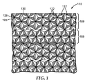
図1、1A、及び1Bは、米国特許第5,936,770号(Nestegardら)において検討されているタイル型再帰反射物品に関する。図1は、ちょうど2つの1次平面内で高入射角において改善された再帰反射性能を示すように、かつこの2つの1次平面のそれぞれにおいて様々な入射角度において実質的に同様の再帰反射性能を示すように設計された、再帰反射キューブコーナーシート材110の構造化表面の一部分の拡大図を表す。構造化表面は、キューブコーナー要素112の配列を含む複数の交互の区域を含む。キューブコーナー要素112は、シート材の片面上の配列中に、光学的に対向する適合ペアとして配設されている。それぞれのコーナーキューブ要素112は、3つの露出した平坦面122を有する3面体プリズムの形状を有している。面122同士の間の二面角は、約90°であるが、先の米国特許第4,775,219号のAppeldornの特許で検討されているように、90°からわずかに偏位してもよい。キューブコーナー要素112は、米国特許第4,588,258号(Hoopman)において開示されているように、傾斜形状を有することが好ましい。かかる傾斜は、高入射角における改善された再帰反射性能の単一の1次平面と、高入射角における改善された再帰反射性能の単一の2次平面と、を画定する。キューブコーナー要素の軸は、米国特許第5,565,151号(Nilsen)で検討されるように「後方」、若しくは「負」の方向に傾いてもよく、又は先の米国特許第4,588,258号(Hoopman)で検討されるように、「前方」若しくは「正」の方向に傾いてもよい。
1, 1A, and 1B relate to a tiled retroreflective article discussed in US Pat. No. 5,936,770 (Nestgard et al.). FIG. 1 shows improved retroreflective performance at high incident angles in exactly two primary planes, and substantially similar retroreflective performance at various incident angles in each of the two primary planes. FIG. 2 represents an enlarged view of a portion of the structured surface of retroreflective cube
シート材110の構造化表面は、およそ90度の向きに配設されたキューブコーナー配列の複数の交互の区域(「タイル」)を含む。したがって、シート材110は、このシート材上に第1の向きに配設されたキューブコーナー要素の配列を含む第1の区域106と、このシート材上に第2の向きに配設されたキューブコーナー要素の第2の区域108と、を含み、高入射角における改善された再帰反射性能の第1の1次平面と、第1の平面に垂直で、高入射角における改善された再帰反射性能の第2の1次平面と、を画定することを特徴とする。
The structured surface of the
第1の区域106は、シート材110の長手方向縁部に実質的に平行に延在する。第1の区域106は、2つの2次の溝セット126、128と、1次の溝セット130と、を含む、3つの互いに交差する溝のセットによって形成される、キューブコーナー要素112の配列を含む。配列中の個々のキューブコーナー要素112は、それらの光学軸が1次の溝130に垂直な面内で傾斜するように形成される。したがって、第1の区域106におけるキューブコーナー配列は、1次の溝130に垂直に、かつシート材110の長手方向縁部に垂直に、延在する、改善された再帰反射性能の1次平面を示す。個々のキューブコーナー要素は、キューブコーナー要素の底面に垂直な軸に対しておよそ8.15度の角度を介して傾けられて、55.5度、55.5度、及び69度の角度を含む基部三角形を画定する。第2の区域108は、シート材の長さに沿って、第1の区域106に実質的に平行に延在し、第2の区域の配列が、第1の区域106における配列に対して90度の向きに配設されていることを除いて、第1の区域106において配設された配列と実質的に同一であるキューブコーナー要素112の配列を含む。対向するキューブコーナー要素を、約7度〜約15度の角度を介して傾けることによって利点が得られる(先の米国特許第4,588,258号(Hoopman)を参照)が、様々な傾斜角度及び様々なキューブサイズが用いられてもよいといえる。
The
図1Aは、先の米国特許第4,588,258号(Hoopman)に従う単一のキューブコーナー配列の再帰反射性能を表す。かかるキューブコーナー配列は、高入射角において改善された再帰反射性能を示し、等輝度等高線の2つの最も広いローブを介して延在する平面によって表わされる、単一の主平面と、高入射角において改善された再帰反射性能を示し、等輝度等高線の2つのより短いローブを介して延在する平面によって表わされる、2次平面と、を示す。したがって、かかる単一のキューブコーナー配列を有するように製造されたシート材は、単一の好ましい向きを有する。図1の実施形態は、高入射角において改善された再帰反射性能を示す2つの平面を設けることにより、この制約を克服するといえる。国際公開第96/42025号(Smithら)に開示されているように、後方に傾けられたキューブは、照射角(entrance angularity)の2つの同様の好ましい平面を有するように構成されてもよい(例えば、50°、65°、65°の基部角度)。照射角の2つの好ましい平面は、必ずしも互いに垂直ではない。 FIG. 1A represents the retroreflective performance of a single cube corner array according to previous US Pat. No. 4,588,258 (Hoopman). Such a cube corner arrangement exhibits improved retroreflective performance at high angles of incidence, with a single principal plane represented by a plane extending through the two widest lobes of isoluminous contours, and at high angles of incidence. A secondary plane represented by a plane that exhibits improved retroreflective performance and extends through two shorter lobes of isoluminous contours. Thus, a sheet material manufactured with such a single cube corner arrangement has a single preferred orientation. The embodiment of FIG. 1 can be said to overcome this limitation by providing two planes that exhibit improved retroreflective performance at high angles of incidence. As disclosed in WO 96/42025 (Smith et al.), The back-tilted cube may be configured to have two similar preferred planes of entrance angularity ( For example, base angles of 50 °, 65 °, 65 °). The two preferred planes of illumination angle are not necessarily perpendicular to each other.
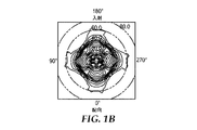
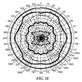
図1Bは、図1に従う2配向型シート材のサンプルから取られた再帰反射輝度値の等輝度等高線のグラフである。再帰反射試験の形状及び測定角度の記述については、ASTM E−808−93b,Standard Practice for Describing Retroreflection(この、より最新版は、ASTM−E−808−01(2009)に表記されている)において与えられており、関係する角度及び他の形状因子もまた、図4と関連して以下で述べられる。図1Bの測定は、0.33度に固定した観測角度及び90度に固定した提示角においてなされた。入射角は、0〜80度で変化させ、シート材は、配向角の360度の範囲を通って回転した。図1Bにおいて、入射角は、同心円によって表わされ、一方、配向角は、グラフの周りに放射状に延在する数字によって表わされる。同心の等輝度等高線は、再帰反射光の相対的な再帰反射性を表す。最大の再帰反射性は、グラフの中心点によって表わされ、同心の等輝度等高線は、カンデラ/ルクス/m2単位で測定された、最大値に対する再帰反射性の5%の減少分を表す。 FIG. 1B is a graph of isoluminance contours of retroreflective luminance values taken from a sample of a bi-oriented sheet material according to FIG. For a description of the retroreflective test shape and measurement angle, see ASTM E-808-93b, Standard Practice for Descriptive Retroreflection (the latest version is described in ASTM-E-808-01 (2009)). Given, the angles and other form factors involved are also discussed below in connection with FIG. The measurements in FIG. 1B were made at an observation angle fixed at 0.33 degrees and a presentation angle fixed at 90 degrees. The incident angle was varied from 0 to 80 degrees, and the sheet material was rotated through a range of 360 degrees of orientation angle. In FIG. 1B, the angle of incidence is represented by concentric circles, while the orientation angle is represented by numbers that extend radially around the graph. Concentric isoluminous contour lines represent the relative retroreflectivity of the retroreflected light. The maximum retroreflectivity is represented by the center point of the graph, and the concentric contours represent the 5% reduction in retroreflectivity relative to the maximum, measured in candela / lux / m 2 units.
図1Bを参照すると、図1の再帰反射シート材は、高入射角における改善された再帰反射性能の、ちょうど4つの広いローブを示している。これら4つのローブは、0度の配向角から始まって90度の間隔(例えば、0度、90度、180度、270度の配向角)で発生している。これら4つのローブは、高照射角における改善された再帰反射性能の2つの1次平面を画定する。第1の平面は、0〜180の向きにおけるシート材の平面を通って延在し、第2の平面は、90〜270の向きにおけるシート材を通って延在する。シート材は、これら2つの平面内で変動する入射角にわたって実質的に同様の再帰反射性能を示すとも言える。使用時には、シート材が最適な再帰反射性能を提供できるように、2つの異なる向きのいずれかにシート材が向けられてもよい。 Referring to FIG. 1B, the retroreflective sheeting of FIG. 1 shows just four wide lobes with improved retroreflective performance at high angles of incidence. These four lobes occur at 90 degree intervals (eg, 0 degree, 90 degrees, 180 degrees, and 270 degrees orientation angles) starting from an orientation angle of 0 degrees. These four lobes define two primary planes with improved retroreflective performance at high illumination angles. The first plane extends through the sheet material plane in the 0-180 orientation and the second plane extends through the sheet material in the 90-270 orientation. It can be said that the sheet material exhibits substantially similar retroreflective performance over incident angles varying in these two planes. In use, the sheet material may be oriented in one of two different orientations so that the sheet material can provide optimal retroreflective performance.
更なる設計の詳細及び図1の物品のような再帰反射物品の変形例については、読者は、先の米国特許第5,936,770号(Nestegard)を参照されたい。 For further design details and variations of retroreflective articles such as the article of FIG. 1, the reader is referred to previous US Pat. No. 5,936,770 (Nestgard).
図2は、タイル張りを採用している別のキューブコーナー再帰反射シート材270の概略平面図である。タイル型シート材270は、Stimsonite Corporation(Niles,IL)によって、商品名STIMSONITE High Performance Grade Reflective Sheeting(ロット1203W、製品番号8432170)で商業的に販売された。タイル型シート材270は、後方に傾けられたキューブコーナー要素の適合ペアの複数のタイル型配列を採用している。シート材270の構造化表面は、シート材270の長手方向縁部272に対して複数の別の向きに位置付けられたキューブコーナー要素の適合ペアの配列の複数の群を含む。キューブコーナー配列は、配列の1次の溝が、シート270の長手方向縁部272に対して0度、30度、60度、及び90度の向きに位置付けられる平面内にあるように向けられている。
FIG. 2 is a schematic plan view of another cube-corner
タイル型シート材270の更なる詳細については、他のタイル型再帰反射物品の記述と同様に、読者は、米国特許第5,822,121号(Smithら)を参照されたい。
For further details of
図3は、米国特許出願公開第2011/0013281号(Mimuraら)において検討されたタイル型キューブコーナー物品310である。キューブコーナー物品310は、構造化表面を有しており、構造化表面における小面は、第1のキューブコーナー配列313−1及び第2のキューブコーナー配列313−2を形成しており、それぞれ、交互の帯状のタイル312−1、312−2に配置されている。この構造化表面は、デカルトのx−y−z座標系のx−y平面として示される基準面を画定する。第1のキューブコーナー配列313−1は、キューブコーナー314−1及び315−1を有する。これらのキューブコーナーは、傾斜している。すなわち、それぞれのキューブコーナーの光学軸(時には対称軸と呼ばれる)は、平面の垂直軸に対して、すなわち、z軸に対して傾いている。第2のキューブコーナー配列313−2は、キューブコーナー314−2及び315−2を有し、これらも傾斜している。キューブコーナー314−1、315−1、314−2、及び315−2について、様々なキューブコーナーの光学軸のx−y平面上への投影が、それぞれ、光学軸314d−1、315d−1、314d−2、及び315d−2として図中に示されている。
FIG. 3 is a tiled
Mimuraの参考文献は、キューブコーナー314−1及び315−1は、順序付けられた内角又は基部角度が(54.918°、66.659°、58.423°)である基部三角形を有し、キューブコーナー314−2及び315−2は、順序付けられた内角が(54.918°、58.423°、66.659°)である基部三角形を有する、実施形態について記述している。基部三角形及びそれらの順序付き角度についての更なる検討が以下でなされる。キューブコーナー314−1のうち所与の1つと、キューブコーナー315−1のうち隣接する1つとは、キューブコーナーの適合ペアを形成する。なぜなら、キューブコーナー314−1は、z軸を中心に180度回転させた場合、キューブコーナー315−1と同じキューブ形状でかつ同じキューブの向きを有するキューブコーナーを生成するためである。キューブコーナー314−2のうち所与の1つと、キューブコーナー315−2のうち隣接する1つとはまた、同じ理由でキューブコーナーの適合ペアを形成する。しかしながら、配列313−1内の任意の所与のキューブコーナーは、配列313−2内の任意のキューブコーナーと同じキューブ形状を有さず、配列313−2内の任意のキューブコーナーと適合ペアを形成しない。 Mimura's reference is that cube corners 314-1 and 315-1 have a base triangle whose ordered interior or base angles are (54.918 °, 66.659 °, 58.423 °) and cubes Corners 314-2 and 315-2 describe an embodiment having a base triangle with ordered interior angles (54.918 °, 58.423 °, 66.659 °). Further discussion on the base triangles and their ordered angles is given below. A given one of cube corners 314-1 and an adjacent one of cube corners 315-1 form a matched pair of cube corners. This is because the cube corner 314-1 generates a cube corner having the same cube shape and the same cube orientation as the cube corner 315-1 when rotated 180 degrees around the z-axis. A given one of cube corners 314-2 and an adjacent one of cube corners 315-2 also form a matched pair of cube corners for the same reason. However, any given cube corner in array 313-1 does not have the same cube shape as any cube corner in array 313-2, and does not have a matching pair with any cube corner in array 313-2. Do not form.
我々は、構造化表面が、タイル型構成に結合された異なるキューブコーナー配列を含む、キューブコーナー物品の群(family)を開発した。様々なキューブコーナー配列の設計上の特徴は、任意選択的にそのそれぞれのタイルの設計上の特徴と組み合わせて、例えば、再帰反射光に対する改善された配向均一性、構造化表面の改善された見かけの空間均一性、とりわけタイルの延在する縁部に沿う、断片化されたキューブコーナー要素の減少(又は、断片化されていないキューブコーナー要素の表面適用範囲の増加)、及び製造の容易さなどの1つ以上の有益な製品特性をもたらすように選択され、一方で、所望に応じて、全体的に高い再帰反射性を有する薄く可撓性のあるキューブコーナーシート材において、1つの、幾つかの、又は全てのこれらの有益な特徴を実現することができる。製造の容易さは、少なくとも2つの可能な態様を有する。1つの態様は、再帰反射キューブコーナーフィルムを製造し得る速度に関し、タイルの大部分又は全てに対するキューブコーナー配列を、フィルムウェブのダウンウェブ(downweb)方向に平行な(かつ、好ましくはそれぞれのタイルの縁部にも平行な)1つの溝セットを有するように設計し、硬化性の材料を工具の構造化表面により容易にかつより速く押し込むことが出来るようにすることによって、この速度を増すことができる。2つ目の態様は、キューブコーナー工具の製造における費用の低減及び簡易さの向上に関し、これらは、1つの配列に対するキューブ形状が、別の向きの配列におけるキューブ形状と同じであるように、かつ/又は別の向きの配列におけるキューブ形状の並べ替えであるように、3つ以下の切削工具の1つのセットのみで切削することができるキューブコーナー配列を使用することにより実現することができる。 We have developed a family of cube corner articles in which the structured surface includes different cube corner arrays coupled in a tiled configuration. Various cube corner array design features, optionally combined with their respective tile design features, for example, improved orientation uniformity for retroreflected light, improved appearance of structured surfaces Spatial uniformity of, especially, reduced fragmented cube corner elements (or increased surface coverage of unfragmented cube corner elements) along the extended edges of the tile, and ease of manufacture, etc. In a thin and flexible cube corner sheet material with an overall high retroreflectivity, if desired, one, several One or all of these beneficial features can be realized. Manufacturability has at least two possible aspects. One aspect relates to the speed at which retroreflective cube corner films can be produced, with the cube corner arrangement for most or all of the tiles being parallel to the downweb direction of the film web (and preferably for each tile). This speed can be increased by designing to have a single groove set (parallel to the edges) and allowing the curable material to be pushed more easily and faster into the structured surface of the tool. it can. The second aspect relates to reduced cost and increased simplicity in the manufacture of cube corner tools, such that the cube shape for one array is the same as the cube shape in another orientation and This can be achieved by using a cube corner array that can be cut with only one set of no more than three cutting tools, such as rearranging cube shapes in an array of different orientations.
我々は、とりわけ、それぞれのタイルが傾斜したキューブコーナー要素の1つの配列を含有する、タイル型構成における複数のキューブコーナー配列を用いる再帰反射シート材などのキューブコーナー物品について本明細書に開示する。タイルは、長く、かつ狭くてもよく、すなわち、延在してもよく、物品の少なくとも2つ又は3つの隣接するタイルのそれぞれにおける、又はタイルの大部分、又は全てのタイルにおける配列は、少なくとも1つの長さ方向の溝を含んでもよく、溝は、タイルの縁部に平行で、固定した面内軸に平行であり、軸は、物品のダウンウェブ方向であってもよい。それぞれのタイルは、狭い幅(例えば、0.2〜5mm、又は1mm未満、又は0.2〜1mm)であってもよく、タイルの縁部に沿う、無駄な断片化されたキューブコーナー及び垂直表面を回避又は低減するために、長さ方向の溝のピッチの整数倍に等しい幅を有してもよい。それぞれの配列は、傾斜平面と、照射角の1次平面と、を有してもよく、複数のタイルに対する照射角の1次平面は、方位角において、傾斜平面よりもより均等に分布していてもよい。 We disclose herein, among other things, cube corner articles such as retroreflective sheeting using multiple cube corner arrays in a tiled configuration, where each tile contains one array of inclined cube corner elements. The tiles may be long and narrow, i.e. extend, and the arrangement in each of at least two or three adjacent tiles of the article, or most of the tiles, or in all tiles is at least It may include one longitudinal groove, the groove being parallel to the edge of the tile and parallel to the fixed in-plane axis, which may be in the downweb direction of the article. Each tile may be narrow (e.g., 0.2-5 mm, or less than 1 mm, or 0.2-1 mm), with wasted fragmented cube corners and vertical along the tile edges In order to avoid or reduce the surface, it may have a width equal to an integral multiple of the pitch of the longitudinal grooves. Each array may have an inclined plane and an irradiation angle primary plane, and the irradiation angle primary planes for a plurality of tiles are more evenly distributed in azimuth than the inclined plane. May be.
本出願は、とりわけ、面内軸を有する基準面を画定する構造化表面を有する物品を更に開示し、構造化表面は、第1、第2、第3のタイルを含む複数のタイルに配置された複数のキューブコーナー配列を含む。第1、第2、及び第3のタイルは、それぞれ第1、第2、及び第3のキューブコーナー配列によって画定され、第1、第2、及び第3のキューブコーナー配列は、それぞれ第1、第2、及び第3の照射角の1次平面を有し、1次平面のそれぞれは、面内軸に対して異なる向きに向いている。 The application further discloses, among other things, an article having a structured surface that defines a reference surface having an in-plane axis, wherein the structured surface is disposed in a plurality of tiles including first, second, and third tiles. Including multiple cube corner arrays. The first, second, and third tiles are defined by first, second, and third cube corner arrays, respectively, and the first, second, and third cube corner arrays are first, second, respectively. The primary planes have second and third irradiation angles, and each of the primary planes is oriented in a different direction with respect to the in-plane axis.
第1、第2、及び第3のタイルはそれぞれ、面内軸に平行な1つのタイルの縁部を含む。第1、第2、及び第3のキューブコーナー配列のそれぞれは、面内軸に平行な1つの所与の溝を含む。第1、第2、及び第3のタイルはそれぞれ、面内軸に平行に伸長していてもよい。第1、第2、及び第3のタイルのそれぞれについて、所与の溝は、長さ方向の溝のピッチを画定する複数の長さ方向の溝のうちの1つであってもよく、第1、第2、及び第3のタイルのそれぞれは、それぞれの長さ方向の溝のピッチの整数倍に等しい幅を有してもよい。第1、第2、及び第3のタイルの幅はそれぞれ、0.2mm〜5mm、又は0.2mm〜1mm、又は0.5mm〜1mmの範囲にあってもよい。複数のタイルは、第1、第2、及び第3のタイル以外の追加のタイルを含んでもよく、追加のタイルは、対応する追加のキューブコーナー配列を有し、追加のキューブコーナー配列の全ては、面内軸に平行な1つの所与の溝を含んでもよい。 The first, second, and third tiles each include one tile edge parallel to the in-plane axis. Each of the first, second, and third cube corner arrays includes a given groove parallel to the in-plane axis. Each of the first, second, and third tiles may extend parallel to the in-plane axis. For each of the first, second, and third tiles, the given groove may be one of a plurality of longitudinal grooves that define a longitudinal groove pitch; Each of the first, second, and third tiles may have a width equal to an integral multiple of the respective lengthwise groove pitch. The widths of the first, second, and third tiles may be in the range of 0.2 mm to 5 mm, or 0.2 mm to 1 mm, or 0.5 mm to 1 mm, respectively. The plurality of tiles may include additional tiles other than the first, second, and third tiles, the additional tiles having corresponding additional cube corner arrays, all of the additional cube corner arrays being , May include one given groove parallel to the in-plane axis.
第1、第2、及び第3のキューブコーナー配列のそれぞれにおけるキューブコーナーは、基部角度の順序付きセットを有する基部三角形によって、傾けられ、特徴付けられ、第1及び第2のキューブコーナー配列についての基部角度の順序付きセットは、互いに等しくてもよく、第1及び第3のキューブコーナー配列についての基部角度の順序付きセットは、互いの並べ替えでもよい。基部角度の順序付きセットの概念は、以下で更に検討される。 The cube corners in each of the first, second, and third cube corner arrays are tilted and characterized by a base triangle having an ordered set of base angles, for the first and second cube corner arrays. The ordered set of base angles may be equal to each other, and the ordered set of base angles for the first and third cube corner arrays may be permuted with respect to each other. The concept of an ordered set of base angles is discussed further below.
第1、第2、及び第3のキューブコーナー配列に対する基部角度の順序付きセットは、代替的に互いに等しくてもよい。次いで、複数のタイルは、第4のキューブコーナー配列によって画定される第4のタイルを更に含み、第4のキューブコーナー配列は、第1、第2、又は第3の照射角の1次平面のいずれにも平行ではない、第4の照射角の1次平面を有し、第4のキューブコーナー配列中のキューブコーナーは、第1のキューブコーナー配列についての基部角度の順序付きセットの並べ替えである、基部角度の順序付きセットを有する基部三角形によって、傾けられ、かつ特徴付けられてもよい。第4のタイルは、面内軸に平行に伸長してもよく、第4のキューブコーナー配列は、面内軸に平行な1つの長さ方向の溝を含んでもよい。 The ordered set of base angles for the first, second, and third cube corner arrangements may alternatively be equal to each other. The plurality of tiles then further includes a fourth tile defined by a fourth cube corner array, wherein the fourth cube corner array is a primary plane of the first, second, or third illumination angle. A cube plane in the fourth cube corner array having a primary plane of a fourth illumination angle that is not parallel to either is a reordering of the ordered set of base angles for the first cube corner array. It may be tilted and characterized by a base triangle with an ordered set of base angles. The fourth tile may extend parallel to the in-plane axis, and the fourth cube corner array may include one longitudinal groove parallel to the in-plane axis.
複数のキューブコーナー配列におけるキューブコーナー配列の全ては、それぞれの照射角の1次平面を有してもよく、照射角の1次平面は、面内軸に対して少なくとも4つの特有の向きを画定してもよい。少なくとも4つの特有の向きに関連したキューブコーナー配列はそれぞれ、面内軸に平行な1つの長さ方向の溝を含んでもよく、それぞれの基部角度の順序付きセットによって特徴付けられてもよく、かかる基部角度の順序付きセットのどの2つも、互いに等しいか、又は互いの並べ替えかのいずれかである。照射角の1次平面はまた、面内軸に対して少なくとも5つの特有の向きを画定してもよい。少なくとも5つの特有の向きに関連したキューブコーナー配列は、それぞれの基部角度の順序付きセットによって特徴付けられてもよく、かかる基部角度の順序付きセットのどの2つも、互いに等しいか、又は互いの並べ替えかのいずれかである。照射角の1次平面はまた、面内軸に対して少なくとも6つの特有の向きを画定してもよい。少なくとも6つの特有の向きに関連したキューブコーナー配列は、それぞれの基部角度の順序付きセットによって特徴付けられてもよく、かかる基部角度の順序付きセットのどの2つも、互いに等しいか、又は互いの並べ替えかのいずれかである。 All of the cube corner arrays in the plurality of cube corner arrays may have primary planes of respective illumination angles, the primary planes of the illumination angles defining at least four unique orientations with respect to the in-plane axis. May be. Each cube corner array associated with at least four distinct orientations may include one longitudinal groove parallel to the in-plane axis and may be characterized by an ordered set of respective base angles, such as Any two of the ordered set of base angles are either equal to each other or permuted with respect to each other. The primary plane of illumination angle may also define at least five unique orientations relative to the in-plane axis. The cube corner array associated with at least five unique orientations may be characterized by an ordered set of respective base angles, any two of which such ordered sets of base angles are equal to each other or aligned with each other. Either one of them. The primary plane of illumination angle may also define at least six unique orientations relative to the in-plane axis. The cube corner array associated with at least six unique orientations may be characterized by an ordered set of respective base angles, any two of which such ordered sets of base angles are equal to each other or aligned with each other. Either one of them.
第1及び第2のタイルは、境界に沿って接するタイルの縁部を有してもよく、境界の近傍の第1のタイル上のキューブコーナーの列の小面と、境界の近傍の第2のタイル上のキューブコーナーの列の小面とは、集合的に複合溝を形成してもよく、この複合溝は、面内軸に平行である。複合溝は、第1のキューブコーナー配列の所与の溝の溝角度とは異なり、第2のキューブコーナー配列の所与の溝の溝角度とも異なる、複合溝角度を有してもよい。 The first and second tiles may have tile edges bordering along the boundary, the facets of the column of cube corners on the first tile near the boundary, and the second near the boundary. The facets of the cube corner rows on the tiles may collectively form a composite groove, which is parallel to the in-plane axis. The composite groove may have a composite groove angle that is different from the groove angle of a given groove in the first cube corner array and different from the groove angle of a given groove in the second cube corner array.
構造化表面は、少なくとも4、又は少なくとも5、又は少なくとも6の30度の照射角における均一性指数を提供してもよい。構造化表面は、少なくとも2、又は少なくとも3、又は少なくとも4、又は少なくとも5の40度の照射角における均一性指数を提供してもよい。 The structured surface may provide a uniformity index at an irradiation angle of 30 degrees of at least 4, or at least 5, or at least 6. The structured surface may provide a uniformity index at an irradiation angle of 40 degrees of at least 2, or at least 3, or at least 4, or at least 5.
本出願はまた、対応する複数のタイルに配置された複数のキューブコーナー配列を含む構造化表面を有する物品であって、構造化表面は、面内軸を有する基準面を画定する、物品を開示する。複数のタイルのそれぞれに対するキューブコーナー配列は、溝が該面内軸に平行に延在する所与の溝セットを有し、複数のタイルのそれぞれに対するキューブコーナー配列は、それに関連した傾斜平面及び照射角の1次平面を有する。複数のタイルに対する照射角の1次平面の特有のものは、傾斜平面の特有のものよりも方位角においてより均一に分布している。 The present application also discloses an article having a structured surface that includes a plurality of cube corner arrays arranged in a corresponding plurality of tiles, the structured surface defining a reference plane having an in-plane axis. To do. The cube corner arrangement for each of the plurality of tiles has a given set of grooves in which the grooves extend parallel to the in-plane axis, and the cube corner arrangement for each of the plurality of tiles has an associated inclined plane and illumination. It has a corner primary plane. The peculiarities of the primary planes of the illumination angles for the tiles are more uniformly distributed in azimuth than the peculiarities of the inclined planes.
照射角の1次平面の特有のものは、最小の角度分離PhiMin1を有してもよく、傾斜平面の特有のものは、最小の角度分離PhiMin2を有してもよく、PhiMin1は、PhiMin2よりも大きくてもよく、又は、PhiMin1は、PhiMin2の少なくとも2倍であってもよい。照射角の1次平面の特有のものは、最大の角度分離PhiMax1を有してもよく、傾斜平面の特有のものは、最大の角度分離PhiMax2を有してもよく、PhiMax1は、PhiMax2よりも小さくてもよい。照射角の1次平面の特有のものに対する角度分布メトリックPhiADM1(以下に記載)は、傾斜平面の特有のものに対する、対応する角度分布メトリックPhiADM2(同様に以下に記載)よりも大きくてもよい。 The characteristic of the primary plane of the illumination angle may have the smallest angular separation PhiMin1, and the characteristic of the tilted plane may have the smallest angular separation PhiMin2, which is more than PhiMin2. It may be large, or PhiMin1 may be at least twice PhiMin2. The characteristic of the primary plane of the illumination angle may have the largest angular separation PhiMax1, the characteristic of the inclined plane may have the largest angular separation PhiMax2, and PhiMax1 is more than PhiMax2. It may be small. The angle distribution metric PhiADM1 (described below) for the primary of the illumination plane may be greater than the corresponding angle distribution metric PhiADM2 (also described below) for the characteristic of the tilted plane.
複数のタイルはそれぞれ、面内軸に平行に伸長されていてもよい。タイルは、0.2mm〜5mm、又は0.2mm〜1mm、又は0.5mm〜1mmの範囲にあるそれぞれの幅を有してもよい。それぞれのタイルに対する所与の溝セットは、かかるタイルに対する長さ方向の溝セットであってもよい。構造化表面は、キューブコーナー配列のうちN個の特有のものにそれぞれ関連するN個の特有の照射角の1次平面を有してもよく、Nは、4、5、又は6であってもよい。複数のタイルは、それぞれ第1、第2、及び第3の傾斜したキューブコーナーの配列を備える、第1、第2、及び第3のタイルを含んでもよく、第1、第2、及び第3の配列は、それに関連した、どの2つも互いに平行ではない、それぞれ第1、第2、及び第3の傾斜平面を有してもよい。第1、第2、及び第3の配列のそれぞれに対して、所与の溝セットは、長さ方向の溝のピッチを画定する長さ方向の溝セットであってもよく、第1、第2、及び第3のタイルのそれぞれは、それぞれの長さ方向の溝のピッチの整数倍に等しい幅を有してもよい。 Each of the plurality of tiles may extend parallel to the in-plane axis. The tiles may have respective widths in the range of 0.2 mm to 5 mm, or 0.2 mm to 1 mm, or 0.5 mm to 1 mm. A given groove set for each tile may be a longitudinal groove set for such tile. The structured surface may have a primary plane of N unique illumination angles each associated with N unique ones of the cube corner array, where N is 4, 5, or 6 Also good. The plurality of tiles may include first, second, and third tiles, each having a first, second, and third inclined cube corner arrangement, the first, second, and third tiles. May have first, second, and third inclined planes, respectively, associated with which no two are parallel to each other. For each of the first, second, and third arrangements, the given groove set may be a longitudinal groove set that defines a longitudinal groove pitch, the first, second, Each of the second and third tiles may have a width equal to an integer multiple of the respective lengthwise groove pitch.
構造化表面は、少なくとも4、又は少なくとも5、又は少なくとも6の30度の照射角における均一性指数を提供してもよい。構造化表面は、少なくとも2、又は少なくとも3、又は少なくとも4、又は少なくとも5の40度の照射角における均一性指数を提供してもよい。 The structured surface may provide a uniformity index at an irradiation angle of 30 degrees of at least 4, or at least 5, or at least 6. The structured surface may provide a uniformity index at an irradiation angle of 40 degrees of at least 2, or at least 3, or at least 4, or at least 5.
本出願はまた、それぞれ第1、第2、及び第3の傾斜したキューブコーナーの配列を備えた少なくとも第1、第2、及び第3のタイルを含む、複数のタイルに分割された構造化表面を有する物品を開示する。第1、第2、及び第3の配列は、それに関連した、どの2つも互いに平行ではない、それぞれ第1、第2、及び第3の傾斜平面を有する。第1、第2、及び第3の配列におけるキューブコーナーは、それぞれ第1、第2、及び第3の基部角度の順序付きセットを有する基部三角形によって、特徴付けられ、第1及び第2の基部角度の順序付きセットは、互いに等しくてもよく、第1及び第3の基部角度の順序付きセットは、互いの並べ替えでもよい。 The application also provides a structured surface divided into a plurality of tiles, including at least first, second, and third tiles each having an array of first, second, and third inclined cube corners. An article having The first, second, and third arrangements have first, second, and third inclined planes, respectively, associated with them, none of which are parallel to each other. The cube corners in the first, second, and third arrangements are characterized by base triangles having an ordered set of first, second, and third base angles, respectively, and the first and second bases The ordered set of angles may be equal to each other, and the ordered set of first and third base angles may be permuted with respect to each other.
第1、第2、及び第3の配列のそれぞれは、溝セットを有してもよく、溝セットの溝は、配列のそれぞれのタイルの縁部に平行に延在する。第1、第2、及び第3の配列のそれぞれは、互いに交差してキューブコーナーを形成する平行な溝の3つのセットによって画定されてもよい。物品はまた、傾斜したキューブコーナーの第4の配列を備える第4のタイルを含んでもよく、第4の配列は、それに関連した、第1、第2、又は第3の傾斜平面のいずれにも平行ではない第4の傾斜平面を有してもよい。第4の配列は、第4の基部角度の順序付きセットを有する基部三角形によって特徴付けられ、第4の基部角度の順序付きセットは、第3の基部角度の順序付きセットと同一でもよい。構造化表面は、少なくとも4、又は少なくとも5、又は少なくとも6の30度の照射角における均一性指数を提供してもよい。構造化表面は、少なくとも2、又は少なくとも3、又は少なくとも4、又は少なくとも5の40度の照射角における均一性指数を提供してもよい。 Each of the first, second, and third arrays may have a groove set, with the grooves of the groove set extending parallel to the edge of each tile of the array. Each of the first, second, and third arrangements may be defined by three sets of parallel grooves that intersect each other to form a cube corner. The article may also include a fourth tile comprising a fourth array of inclined cube corners, the fourth array being in any of the first, second, or third inclined planes associated therewith. You may have the 4th inclined plane which is not parallel. The fourth array is characterized by a base triangle having an ordered set of fourth base angles, where the ordered set of fourth base angles may be the same as the ordered set of third base angles. The structured surface may provide a uniformity index at an irradiation angle of 30 degrees of at least 4, or at least 5, or at least 6. The structured surface may provide a uniformity index at an irradiation angle of 40 degrees of at least 2, or at least 3, or at least 4, or at least 5.
関連する方法、システム、及び物品についても検討する。 Consider related methods, systems, and articles.
本出願のこれらの態様及び他の態様は、以下の「発明を実施するための形態」より明らかになるであろう。しかしながら、上記の概要は、いかなる場合においても特許請求される主題に対する限定として解釈されるべきではなく、手続時に補正され得る添付の「特許請求の範囲」によってのみ定義されるものである。 These and other aspects of the present application will become apparent from the following Detailed Description. However, the above summary should not be construed as limiting the claimed subject matter in any way, but should be defined only by the appended claims, which may be amended during the procedure.
図中、同様の参照番号は、同様の要素を示す。 In the drawings, like reference numerals indicate like elements.
我々は、物品において、又はその製造において、幾つの、かつどの部分の開示された設計上の特徴が用いられているかに応じて、多数の有益な製品の特性をもたらすことができるキューブコーナー物品の群を開発した。 We have a number of cube corner articles that can provide a number of beneficial product characteristics depending on how many and which parts of the disclosed design features are used in the article or in its manufacture. A group was developed.
設計上の特徴について更に詳細を検討する前に、まず、図4を参照して、再帰反射物体の照射及び観測形状に関連する特定のパラメータについて概観する。図中、物品450は、前面430を有する。物品450は、再帰反射性を提供するための(例えば、物体の後ろ側又は裏側に)構造化表面を有してもよい再帰反射シート又は他の再帰反射物体であってもよい。物品は、概ね基準面内にあると仮定する。図において、デカルトのx−y−z座標系が示されており、基準面は、x−y平面に対応すると仮定する。なお、所与の物品が、湾曲している、曲がっている、ないしは平坦ではない場合、平面に近似するのに十分小さい物品の部分は、分離して考えられてもよい。物品450及び基準面はまた、面法線軸448を画定し、この軸は、基準面に垂直であり、したがって、z軸に平行である。我々はまた、時に基準マークと呼ばれる、特定の面内軸465を画定することができる。面内軸465は、当然、法線軸448に垂直であり、物品450の前面上の、又は別の関連する部分上の、ある点において法線軸と交差する。面内軸465は、例えば、ダウンウェブ方向、特定の溝セットの溝方向、又は物品の縁部若しくは物品のタイルの縁部などの、物品450の平面における対象の特定の方向で選択されてもよい。
Before discussing further details about the design features, first, with reference to FIG. 4, an overview of the specific parameters associated with the illumination of the retroreflective object and the observed shape will be given. In the figure, the
物品450は、光源416によって照射され、検出器466は、物品450によって反射した光の輝度又は強度を測定する。光源416及び検出器466は、物品450に対して任意の位置に示される。光源416から物品450へ伸びる照射軸は、法線軸448に対して角度βをなす。照射軸及び法線軸448は、x−y平面に垂直な入射平面を画定し、面内軸465に対して角度ωをなす。検出器466から物品450へ延在する観測軸は、照射軸に対して角度αをなす。観測軸及び照射軸は、平面を画定し、この平面は、照射平面に対して角度γをなす。これらの角度は、以下のように呼ばれる。
α−観測角
β−入射角
γ−提示角
ω−配向角
α-Observation angle β-Incident angle γ-Presentation angle ω-Orientation angle
これらの角度、及び本明細書で検討される他の角度は、別途注記がない限り、弧度の単位で表現される。 These angles, and other angles discussed herein, are expressed in units of arc degrees unless otherwise noted.
物品450などの物品の反射輝度、あるいは、反射率、再帰反射率、又は単に輝度と呼ばれるものは、RAと表わされ、概ね全ての4つの角度α、β、γ、及びωの関数である。反射輝度は、法線方向の照度及び物品の表面積(又は、その被試験部分)で割った物品の反射光度であり、平方メートルあたりのルクスあたりのカンデラの単位で表現され、cd/(lux・m2)又はcd/lx/m2と略記される。α、β、γ、及びωの値が指定されていない場合、0.2度の観測角α、−4度の入射角β、0度の提示角γ、0度の配向角ωを仮定するのが一般的である。物品450などの物品の全光反射(TLR)は、キューブコーナーの活性領域の割合又は比率と、光線強度との積に関連している。別途記載のない限り、TLRは、物品によって反射される全光を、その基部が物品の前面と一致する(図4の前面430を参照)半球に積分することによって算出され、半球内部の全ての方向ベクトルは、図4の座標系を基準として非負のz成分を有する。半球は、観測角αの全範囲、及び提示角γの全範囲を画定する。しかしながら、場合によっては、TLRは、例えば、観測角α中にその半角が4度である円錐の範囲を定める検出器に対応する部分など、半球のある部分のみに反射される光に基づいて算出されてもよい。したがって、TLRは概ね、入射角β及び配向角ωのみの関数である。物品450などの物品についての、等強度プロットとも呼ばれる等輝度等高線グラフは、図1A又は図1Bなどのようなグラフであり、物品の再帰反射性能(これは、通常はTLRによって表わされるが、所望に応じて、代わりに、特定の提示角γ(典型的には0度)及び観測角α(典型的には0.2度)における再帰反射率RAによって表わされる)は、入射角β及び配向角ωの関数として等高線の形式でプロットされる。
What is referred to as reflected brightness, or reflectance, retroreflectance, or simply brightness, of an article such as
物品450などの物品に対する照射角の1次平面は、(例えば、配向角ωに関して定義される)入射平面を指し、この1次平面において、等輝度等高線グラフは、最大範囲のローブを示す。例えば、上述の図1Aのグラフは、配向角90度、270度に対応する1つの照射角の1次平面を有し、上述の図1Bのグラフは、一方は、配向角90度、270度に対応し、他方は、配向角0度、180度に対応する、2つの照射角の1次平面を有する。照射角の1次平面が1つのみ存在する場合には、かかる平面はまた、照射角の中心的平面とも呼ばれる。したがって、他の照射角の1次平面が存在しないため、例えば、図1Aの照射角の1次平面はまた、照射角の中心的平面である。(配向角0度、180度に対応する)照射角2次平面は、照射角の1次平面のローブよりも小さな範囲のローブを有している。
The primary plane of the illumination angle for an article, such as
物品450などの物品の均一性指数(「UI」)は、配向角ωの関数として、物品のTLRがどれだけ変化するかの尺度である。本明細書の目的のために、UIは、配向角ωの全範囲にわたって、10度又は15度などの所定の増分におけるTLRを求めることによって算出される。かかるTLR値の全ての、最小値、最大値、及び平均値が求められる。次いで、UIは、最大TLR値と最小TLR値との間の差分で割った平均TLR値と等しくなるように算出される。UIは、入射角βの関数に過ぎない。
The uniformity index (“UI”) of an article, such as
ここで、多数の有益な製品特性をもたらす特有の組み合わせにおいて用いることができると我々が発見したタイル型キューブコーナー物品の設計上の特徴の検討に戻る。上述したように、タイル型構成を有する多数のキューブコーナー物品は、これまでに開示されている。かかる物品の多くが、商用で製造、販売、及び使用されてきた。その結果、利用者の大多数は、それらの物品が彼らの意図する目的に対して満足のいくものであると判った。 Here, we return to a review of the design features of tiled cube corner articles that we have found that can be used in unique combinations that provide a number of beneficial product properties. As mentioned above, numerous cube corner articles having a tiled configuration have been previously disclosed. Many such articles have been manufactured, sold, and used commercially. As a result, the majority of users have found that the items are satisfactory for their intended purpose.
一般的に市場においてタイル型キューブコーナー製品が広く受け入れられているにも関わらず、我々は、かかる物品のより一層の採用について、何らかの課題又は障害が存在するかどうか検討を行った。我々が特定した課題及び障害は、必ずしもタイル型キューブコーナー物品に関連した「問題」であると他者によって認識されなかった。この作業の過程において、我々は、本明細書の他の箇所で説明するように、設計上の特徴の特有の組み合わせの使用を通じて得られるであろう利点又は利益にも気づいたが、再び、これらの利点又は利益は、必ずしも他者によって認識される何らかの特定の「問題」に関連してはいなかった。 Despite the wide acceptance of tiled cube corner products in the market in general, we have examined whether there are any challenges or obstacles to further adoption of such articles. The challenges and obstacles we identified were not necessarily recognized by others as “problems” associated with tiled cube corner articles. In the course of this work, we have also noticed the benefits or benefits that would be gained through the use of specific combinations of design features, as described elsewhere in this document. The benefits or benefits of were not necessarily related to any particular “problem” that was recognized by others.
我々が特定した1つの課題は、配向角についての等強度プロットの不均一性の程度であった。例えば、図1Bの等強度プロットに関連したタイル型キューブコーナーシート材について、(典型的に0度及び90度の向きに対応している)垂直及び水平の入射平面における照射角は、とても似通っている。しかしながら、水平から角度45度などの他の向きにおいては、全く異なる照射角が得られる。かかるタイル型シート材は、とりわけ、再帰反射性を提供するためにキューブコーナー要素ではなくガラスビーズの層を用いるシート材と比べると、配向角において0〜180度の全範囲にわたって不均一の再帰反射性能を示す。ビーズ型再帰反射シート材は、多くの用途で依然として用いられており、より多くのタイル型キューブコーナーシート材がビーズ型シート材に置き換わることができるよう検討するべき1つの課題は、配向角の関数としての再帰反射性能におけるより優れた均一性を得ることである。ガラスビーズの円形対称性のおかげで、ビーズ型シート材は典型的に、配向角の全範囲にわたってその再帰反射性能において高い均一性を有する。 One challenge we identified was the degree of non-uniformity of the isointensity plots for orientation angles. For example, for a tiled cube corner sheet material associated with the isointensity plot of FIG. 1B, the illumination angles in the vertical and horizontal incidence planes (typically corresponding to 0 and 90 degree orientations) are very similar. Yes. However, in other orientations such as 45 degrees from the horizontal, a completely different illumination angle is obtained. Such a tiled sheet material, among other things, has a non-uniform retroreflection across the entire range of 0-180 degrees in orientation angle when compared to a sheet material that uses a layer of glass beads rather than cube corner elements to provide retroreflectivity. Show performance. Bead-type retroreflective sheeting is still used in many applications, and one challenge to consider so that more tile-type cube corner sheeting can be replaced by beaded sheeting is a function of orientation angle. To obtain better uniformity in retroreflective performance. Thanks to the circular symmetry of glass beads, bead-type sheet materials typically have a high uniformity in their retroreflective performance over the entire range of orientation angles.
とりわけ、ビーズ型再帰反射シート材を現在用いている用途においてタイル型キューブコーナー物品を用いることを検討する場合、別の課題は、物品の見かけの空間均一性に関する。ビーズ型シート材は典型的に、高い空間均一性の程度を有する。すなわち、相対的に近い観察距離であっても、かかるシート材は典型的に、シート材の表面にわたる様々な場所における外観にわずかの差を示すか、又は全く有意な差を示さない。しかしながら、図1Bに関連したようなタイル型キューブコーナー物品は、およそ10〜20フィート(3〜6メートル)よりも近い距離から観察した場合、顕著に空間的に不均一である(縞がある)外観を有する。かかる空間不均一性は、多くの用途において好ましくはない、又は問題があるとはみなされないが、我々は、そのことによって、タイル型キューブコーナー物品のより広範な用途に対して課題又は障害を課し得ることに気づいた。観察距離が近くなること、すわなち、およそ10〜20フィート(3〜6メートル)よりも近くなることは、ビーズ型シート材の購入者が、例えば、シート材が自動車のナンバープレートに用いられることになるなどの購入決定に関するシート材を評価する場合に通常起こり得る。より近い距離における視覚的な不均一性は、個々のタイルの幅又は他の特徴的な最小横寸法にいくぶん起因する。タイル型キューブコーナー製品の大部分は、少なくとも0.150インチ(3.8mm)、より典型的には0.375インチ(9.5mm)のタイル幅を有する。より小さな寸法及びより狭いタイル、例えば、幅0.040インチ(1mm)以下などが、より視覚的に均一である外観を提供するために用いることができる。しかしながら、かかる狭い幅は、構造化表面の工具を個々の細片に切削するために、従来の放電加工(EDM)を用いる場合、かつタイル型キューブコーナー工具を生成するために、従来のレイアップ(lay-up)手法を用いて、この細片を互いに並べて配置する場合、作業するのが困難になり得る。かかる個々の狭い細片の断面アスペクト比(幅で割った高さ又は厚み)は、約1以下の値を示し、結果として、個々の細片は、ワイヤーに類似し、かつワイヤーのような動きをする。かくして、それらは、ねじれ、又は曲がる傾向があり、結果的に、レイアッププロセス中に他の狭い細片又はタイルと密接に位置を合わせて保持することが難しくなり得る。 In particular, when considering using tiled cube corner articles in applications that currently use beaded retroreflective sheeting, another challenge relates to the apparent spatial uniformity of the article. Bead-type sheet materials typically have a high degree of spatial uniformity. That is, even at relatively close viewing distances, such sheet materials typically show little or no significant difference in appearance at various locations across the surface of the sheet material. However, tiled cube corner articles such as those associated with FIG. 1B are significantly spatially non-uniform (streaked) when viewed from a distance closer than approximately 10-20 feet (3-6 meters). Appearance. Such spatial non-uniformity is not considered undesirable or problematic in many applications, but it imposes challenges or obstacles to the wider use of tiled cube corner articles. I realized I could do it. The closer observation distance, i.e., closer than about 10-20 feet (3-6 meters), means that a purchaser of beaded sheet material, for example, uses the sheet material for an automobile license plate. This can usually occur when evaluating sheet materials for purchase decisions such as. Visual non-uniformity at closer distances is due in part to individual tile widths or other characteristic minimum lateral dimensions. The majority of tiled cube corner products have a tile width of at least 0.150 inches (3.8 mm), more typically 0.375 inches (9.5 mm). Smaller dimensions and narrower tiles, such as 0.040 inches (1 mm) or less in width, can be used to provide a more visually uniform appearance. However, such a narrow width is not possible with conventional layups when using conventional electrical discharge machining (EDM) to cut structured surface tools into individual strips and to produce tiled cube corner tools. If this strip is placed side by side using a (lay-up) approach, it can be difficult to work with. The cross-sectional aspect ratio (height or thickness divided by width) of such individual narrow strips shows a value of about 1 or less, so that the individual strips are similar to wire and move like wire do. Thus, they tend to twist or bend, and as a result, it can be difficult to hold closely aligned with other narrow strips or tiles during the layup process.
別の課題は、タイル型キューブコーナー物品の視覚的不均一性にも影響を与え、隣接するタイルにおける溝の向きの差異の程度に関する。隣接するタイルにおける溝の向きの極端な差異により、人間の観察者によって気づかれるような、かかるタイル間の外観における認知される差異を増幅する場合がある。対照的に、隣接するタイル内に、例えば、タイルの縁部に平行に、かつ特定の面内軸に平行に、同一の又は類似の向きを有する溝を設けることによって、タイル間の外観上の差位を低減することができ、それによって、タイル型物品の視覚的均一性を増大させ、視覚的不均一性を低減させることができる。 Another challenge also affects the visual non-uniformity of tiled cube corner articles and relates to the degree of difference in groove orientation in adjacent tiles. Extreme differences in groove orientation in adjacent tiles may amplify perceived differences in appearance between such tiles as noticed by a human observer. In contrast, by providing grooves in adjacent tiles that have the same or similar orientation, for example, parallel to the edges of the tile and parallel to a particular in-plane axis, The differential can be reduced, thereby increasing the visual uniformity of the tiled article and reducing the visual non-uniformity.
別の課題は、タイル型工具のレイアップに備えて、(EDMか、又は任意の他の適切な手法によって)個々のタイルを切削する方法に関し、その切削の方法は、タイルの縁部に沿って位置するキューブコーナーの完全性及び有効性に影響を与える。図1の、例えば、タイル、又は区域106を参照する。これらのタイルにおいて、タイルの延在する縁部に隣接して位置する構造体は、配列における他のキューブコーナーに比べると、キューブコーナーの全ての3つの完全な状態の小面よりも少ない小面を有している。かかる構造体は、本明細書では、断片化されたキューブコーナー要素と呼ばれる。配列における完全な(断片化されていない)キューブコーナーに比べると、かかる構造体は、欠落した小面(又はその一部)により全体的に又は部分的に無駄なものになる。断片化された多数のキューブコーナー要素、すなわち、タイルの縁部でキューブコーナー要素の一部が切断され、それによってタイルから欠落していることを除いて、配列における他の箇所のキューブコーナー要素と同一である構造体をもたらす方法で、タイルの幾つか又は多数を切削することは、2つの理由で望ましくない。第1に、断片化されたキューブコーナーにより、断片化されたキューブコーナーが占有するタイル型物品の全体の表面積の比率又は割合に比例して、タイル型物品の再帰反射輝度が減少する。第2に、タイルの縁部に沿う断片化されたキューブコーナー要素において、垂直、又はほぼ垂直の壁が生成される。かかる垂直の壁により、その後の複数世代にわたる工具の複製が製造されるとき、又はめっきされるとき、分離の問題を引き起こす場合がある。
Another challenge relates to a method of cutting individual tiles (either by EDM or any other suitable technique) in preparation for tile-type tool layup, the cutting method being along the edge of the tile. Affects the integrity and effectiveness of the cube corner. Reference is made, for example, to tiles or
視覚的不均一性に関連して既に上述したように、隣接するタイルにおける溝の向きが異なる差異の程度により、製造の容易さに関する別の課題にも影響が出る。したがって、タイルの大部分又は全てが特定の面内方向に整列した1つの溝セットを有するようにタイル型物品を設計し、その面内方向がタイル型形状(適切に構成された外側表面を有する柱体又は円筒など)を有するキューブコーナーキャビティ工具への硬化性材料(流動性を有する重合体、又は重合体の前駆物質など)の流れの方向に平行になるように製造を行うことによって、硬化性材料は、より容易に高い忠実度で、その結果、他の場合よりも速いライン速度で確実にかつ完全に構造体を充填又は複製することができることを我々は発見した。硬化性材料の流れの方向は、工具と、例えば、塗工用ダイ又は流体材料の回転バンクなどの流体源との間の相対的な動きの方向によって定義されてもよく、この方向はまた、製造されるキューブコーナーシート材又は他の物品のダウンウェブ方向であることが好ましい。面内方向はまた、物品内のタイルの大部分又は全てのうち少なくとも1つの縁部に平行であることが好ましい。 As already mentioned above in connection with visual non-uniformity, the degree of difference in the groove orientation in adjacent tiles also affects other challenges related to ease of manufacture. Thus, a tiled article is designed such that most or all of the tiles have one groove set aligned in a particular in-plane direction, the in-plane direction having a tile-shaped shape (with an appropriately configured outer surface). Curing by making it parallel to the direction of flow of curable material (such as flowable polymer or polymer precursor) to cube corner cavity tools with columns or cylinders) We have found that sex materials can more easily fill and replicate structures with greater fidelity and, as a result, more reliably and completely at higher line speeds. The direction of flow of the curable material may be defined by the direction of relative movement between the tool and a fluid source, such as a coating die or a rotating bank of fluid material, for example, It is preferably in the downweb direction of the cube corner sheet material or other article being manufactured. The in-plane direction is also preferably parallel to at least one edge of most or all of the tiles in the article.
開示するタイル型キューブコーナー物品は、上述した、又は本明細の他の箇所で述べられる課題の全てを解決するために設計された製品特性を含有する必要はなく、代わりに、それらは、かかる特性のいくつかのみを含有してもよい。特性の幾つかは、相乗的である。例えば、タイルの大部分又は全てが、特定の面内方向に整列した1つの溝セットを有するようにタイル型物品が設計される場合、視覚的均一性も増大させることができ、製品をより容易にかつより速く製造することができる。更に、面内方向がタイルの大部分又は全ての縁部に整列するように物品がまた設計される場合、タイルの幅をタイルの縁部に整列した溝のピッチの整数倍に等しくすることにより、かつ、それぞれのタイルの外側の溝の頂点をタイルの縁部に一致させることにより、それらの縁部に沿う断片化されたキューブコーナーの形成を回避又は最小化することができる。 The disclosed tiled cube corner articles need not contain product characteristics designed to solve all of the problems described above or described elsewhere herein; instead, they do not have such characteristics. Of some of them. Some of the properties are synergistic. For example, if the tiled article is designed so that most or all of the tiles have one groove set aligned in a particular in-plane direction, visual uniformity can also be increased, making the product easier And can be manufactured more quickly. Furthermore, if the article is also designed so that the in-plane direction is aligned with most or all edges of the tile, by making the width of the tile equal to an integer multiple of the pitch of the grooves aligned with the edges of the tile And by making the outer groove vertices of each tile coincide with the edges of the tiles, the formation of fragmented cube corners along those edges can be avoided or minimized.
したがって、キューブコーナー工具の製造を、上述した課題の幾つか又は全てを解決するように実行することができる。 Thus, cube corner tool manufacturing can be performed to solve some or all of the above-mentioned problems.
1つの手法では、単一種類のキューブ形状を使用して、それぞれ3つの異なるキューブの向きを有する配列を持つ、3つの異なる種類のタイルを生成することができる。この点に関して、図5の配置510が参照される。キューブ形状によって、我々は、キューブコーナー、又はキューブコーナーの適合ペア、又はかかるキューブコーナーの配列の特徴付けについて、以下で更に検討するように、(複数の)キューブコーナーに関連した基部三角形の順序付き角度に関して言及する。図5の配置510は、3つのキューブコーナー配列:513−1、513−2、及び513−3を有する。これらの配列のうちそれぞれ1つにおいて、キューブコーナーは、3つの交差する平行な溝のセットによって形成又は画定される。配列513−1では、溝方向517Aに全て平行な溝517−1は、溝方向518Aに全て平行な溝518−1と交差し、溝方向519Aに全て平行な溝519−1とも交差する。描画された実施形態において、溝方向及びピッチは、溝方向518A、517Aが56度の角度を形成し、溝方向517A、519Aが56度の角度を形成し、溝方向519A、518Aが68度の角度を形成する、前方に傾斜したキューブの適合ペアを形成するように選択される。したがって、この配列におけるキューブコーナーは、(56、56、68)のキューブ形状を有する。これらの交差角度は、例証的なものであり、限定的ではないとみなされるべきである。更に、キューブの光学軸は、この場合では溝方向517Aに垂直である、傾斜平面と呼ばれる平面(又は、平行な平面のセット)において傾いている。このキューブ形状がポリカーボネートなどの屈折率1.59の透明材料において実施される場合、結果は、等強度プロット502Aになる。等強度プロットは、照射角の1次平面503Aを示し、本ケースでは、この平面は、配列513−1に対する傾斜平面と一致する。
In one approach, a single type of cube shape can be used to generate three different types of tiles, each having an array with three different cube orientations. In this regard, reference is made to the arrangement 510 of FIG. Depending on the cube shape, we will order the base triangles associated with the cube corner (s) as discussed further below for the characterization of the cube corners, or the matching pairs of cube corners, or the arrangement of such cube corners. Mention the angle. The arrangement 510 of FIG. 5 has three cube corner arrays: 513-1, 513-2, and 513-3. In each one of these arrangements, the cube corner is formed or defined by a set of three intersecting parallel grooves. In the array 513-1, the grooves 517-1 that are all parallel to the
配列513−2では、溝方向517Bに全て平行な溝517−2が、溝方向518Bに全て平行な溝518−2と交差し、溝方向519Bに全て平行な溝519−2とも交差する。溝方向及びピッチは、再度、溝方向518B、517Bが56度の角度を形成し、溝方向517B、519Bが56度の角度を形成し、溝方向519B、518Bが68度の角度を形成する、前方に傾斜したキューブの適合ペアを形成するように選択される。したがって、この配列におけるキューブコーナーは、(56,56,68)のキューブ形状、すなわち、配列513−1と同じキューブ形状であるが、配列513−1と513−2との間の相対的な方位角回転によって示されるような異なる向きにあるキューブ形状を有する。配列513−2中のキューブの光学軸は、この場合では溝方向517Bに垂直である、傾斜平面と呼ばれる平面(又は、平行な平面のセット)において傾いている。このキューブ形状が屈折率1.59の同じ透明材料において実施される場合、結果は、等強度プロット502Bになる。等強度プロットは、照射角の1次平面503Bを示し、この平面は、配列513−2に対する傾斜平面と一致する。
In the array 513-2, the grooves 517-2 that are all parallel to the
配列513−3では、溝方向517Cに全て平行な溝517−3が、溝方向518Cに全て平行な溝518−3と交差し、溝方向519Cに全て平行な溝519−3とも交差する。溝方向及びピッチは、再び、溝方向518C、517Cが56度の角度を形成し、溝方向517C、519Cが56度の角度を形成し、溝方向519C、518Cが68度の角度を形成する、前方に傾斜したキューブの適合ペアを形成するように選択される。したがって、この配列中のキューブコーナーは、(56,56,68)のキューブ形状、すなわち、配列513−1及び513−2と同じキューブ形状であるが、配列513−1、513−2、513−3の間の相対的な方位角回転によって示されるような、異なる向きにあるキューブ形状を有する。配列513−3中のキューブの光学軸は、この場合では溝方向517Cに垂直である、傾斜平面と呼ばれる平面(又は、平行な平面のセット)において傾いている。このキューブ形状が屈折率1.59の同じ透明材料において実施される場合、結果は、等強度プロット502Cになる。等強度プロットは、照射角の1次平面503Cを示し、この平面は、配列513−3に対する傾斜平面と一致する。
In the array 513-3, the grooves 517-3 that are all parallel to the
同じキューブ形状を有するが向きの異なる、全ての3つの配列513−1、513−2、513−3を形成することにより全ての配列中に同じ溝角度が現れる。この点について、溝は、傾斜した表面間に形成される、延在した開放空間を指し、この傾斜した表面は、2つの交差する平面を実質的に画定し、この2つの平面は、溝の頂点(例えば、基部又は底部)に対応する線に沿って交差する。2つの平面間の二面角は、溝の夾角、すわなち「溝角度」である。製造公差の範囲内の意図しない変動性による、かつ/又は2次的な設計上の特徴を提供する目的のための意図的な変動性による、交差する平面のうち一方又は両方に関する完全な平面性からの軽微なずれ、及び線又は頂点に関する完全な直線性からの軽微なずれがあってもよい。任意のかかる軽微なずれは、典型的に大変小さく、関連する面又は線の画像又は縮尺図面を直接に目視しても目立たない程度であろう。溝を含有する構造化表面の、反転した複製、すなわちネガティブレプリカは、溝の延在した開放空間に対応する延在した立体空間を有し、ポジティブ構造が検討されているか、又はネガティブ(反転した)構造が検討されているかに関わらず、溝及びその特徴を検討することができるように、概略的に、かかる延在した立体空間又は「反転溝」もまた、「溝」という用語の範囲内にあると広くみなしてもよい。本明細書で検討する誤差の範囲内で、同じ溝角度のセットが図5の全ての配列中に存在する(実際、それぞれの配列中に2つの固有の溝角度のみが存在する)ために、配列は全て、まず、例えば、ダイヤモンド工具又は他の好適な切削工具の単一のセットで銅又は他の好適な材料製のマスター基板上でフライカット又は治されて(rule)、製造することができる。これは、(例えば、ダイヤモンド工具の設定数を最小化するなど)製造プロセスを単純化し、在庫を減らすために有利である。 By forming all three arrays 513-1, 513-2, 513-3 having the same cube shape but different orientation, the same groove angle appears in all arrays. In this regard, the groove refers to an extended open space formed between the inclined surfaces, the inclined surface substantially defining two intersecting planes, the two planes being Intersect along a line corresponding to a vertex (eg, base or bottom). The dihedral angle between the two planes is the depression angle of the groove, that is, the “groove angle”. Full flatness for one or both of the intersecting planes due to unintended variability within manufacturing tolerances and / or due to intentional variability for the purpose of providing secondary design features There may be minor deviations from, and minor deviations from perfect linearity with respect to lines or vertices. Any such minor deviations are typically very small and may not be noticeable by direct visual inspection of the relevant surface or line image or scale drawing. An inverted replica of the structured surface containing the groove, i.e. a negative replica, has an extended three-dimensional space corresponding to the extended open space of the groove and a positive structure is being considered or negative (inverted). In general, such an extended space or “inverted groove” is also within the scope of the term “groove” so that the groove and its features can be considered regardless of whether the structure is being considered. It may be considered widely. Within the error discussed herein, the same set of groove angles exists in all arrays of FIG. 5 (in fact, there are only two unique groove angles in each array) All arrays can be manufactured by first fly-cutting or ruled on a master substrate made of copper or other suitable material, for example with a single set of diamond tools or other suitable cutting tools. it can. This is advantageous for simplifying the manufacturing process (eg, minimizing the set number of diamond tools) and reducing inventory.
図5の3つの配列は、配列、及び配列のそれぞれの照射角の1次平面が異なる方向を向いているとしても、溝方向が特定の固定の面内軸に平行である溝又は溝セットをそれぞれの配列が含むように、特定の方法で向けられている。この点については、我々は、配列513−1、513−2、513−3の全てが、図5に示すデカルトのx−y−z座標系のx−y平面内にある、又はx−y平面に平行に延在すると仮定している。固定された面内軸とみなすことができるy軸は、配列513−1中の溝517−1の溝方向517Aに平行、配列513−2中の溝519−2の溝方向519Bに平行、配列513−3中の溝518−3の溝方向518Cに平行であるように配列及び座標系が配置されている。3つの配列の照射角の1次平面と同様に、3つの配列の傾斜平面が全て異なる方向に向いている間、この条件は満足される。
The three arrays in FIG. 5 are grooves or groove sets in which the groove direction is parallel to a specific fixed in-plane axis, even though the primary planes of the respective irradiation angles of the arrays are in different directions. Each sequence is directed in a specific way to include. In this regard, we have all of the arrays 513-1, 513-2, 513-3 in the xy plane of the Cartesian xyz coordinate system shown in FIG. It is assumed that it extends parallel to the plane. The y-axis, which can be regarded as a fixed in-plane axis, is parallel to the
図5の配列には、多くの改変を行うことが可能である。例えば、3つの配列中のそれぞれの溝セット及びキューブコーナーについて、溝のピッチ、溝の深さ、及びキューブの高さは、同じであると仮定されていた。しかしながら、そうである必要はなく、全てが、(56,56,68)などの同じキューブ形状、同じそれぞれの傾斜平面、及び同じそれぞれの照射角の1次平面を維持する間は、1つの配列の溝のピッチ、溝の深さ、及びキューブの高さは、他の配列のうち一方又は両方に対して変更されてもよい。したがって、1つの配列中のキューブコーナーは、別の配列中のキューブコーナーよりも大きくても(例えば、より高くても、かつ/又はより広くても)よく、更に別の配列中のキューブコーナーと同じ寸法であっても、又はより小さくても(例えば、より低くても、かつ/又はより狭くても)よい。他の実施形態では、それぞれの配列の1つの溝又は溝セットがy軸などの指定された面内方向と平行な溝方向を有するという条件を依然として維持する間、他の配列のうち一方又は両方に対して、1つの配列中に異なるキューブ形状を用いることができる。異なるキューブ形状は、正又は負の傾斜の程度を有してもよい。更に、所与のキューブ配列の傾斜平面は、照射角の1次平面に一致してもよく、一致しなくてもよく、照射角の1次平面は、照射角の中心的平面、又は複数の照射角の1次平面のうちの1つであってもよい。3つの別個のキューブコーナー配列のみを図5に示したが、例えば4つ、5つ、又は6つ以上の、より多くの別個のキューブコーナー配列が代替の実施形態で用いられてもよい。キューブコーナー配列は、それらを構成するキューブコーナーが、例えば、キューブ形状、キューブの向き、及び/又はキューブの寸法など、任意の物質的方法において異なる場合に、別個であると言うことができる。3つ以上の別個のキューブコーナー配列はまた、連続して繰り返し現れてもよく、それぞれの配列がタイル型物品中に複数回現れる。また、図5に示した配列とは異なり、配列のうち1つ、幾つか、又は全てにおけるキューブコーナーは、正確に3つの交差する平行溝のセットによって画定される必要はない。したがって、キューブコーナーは、平面視において(キューブコーナーの形状は、依然としてかかるキューブコーナーに関連した基部三角形によって画定されるものの、)単純な三角形の形状ではない底面を有してもよい。この点について、米国特許第5,557,836号(Smithら)、第5,914,813号(Smithら)、第6,083,607号(Mimuraら)、第6,390,629号(Mimuraら)、及び第6,540,367号(Bensonら)、並びに国際公開第2004/061489号()、並びに日本特許公報JP 11−305017(Mimuraら)が参照される。 Many modifications can be made to the arrangement of FIG. For example, for each groove set and cube corner in the three arrays, the groove pitch, groove depth, and cube height were assumed to be the same. However, this need not be the case, all in one array while maintaining the same cube shape, such as (56, 56, 68), the same respective inclined plane, and the primary plane of the same respective illumination angle. The pitch of the grooves, the depth of the grooves, and the height of the cubes may be varied for one or both of the other arrangements. Thus, a cube corner in one array may be larger (eg, higher and / or wider) than a cube corner in another array, and a cube corner in another array The dimensions may be the same or smaller (eg, lower and / or narrower). In other embodiments, one or both of the other arrays while still maintaining the condition that one groove or groove set of each array has a groove direction parallel to a specified in-plane direction, such as the y-axis. In contrast, different cube shapes can be used in an array. Different cube shapes may have a degree of positive or negative slope. Further, the inclined plane of a given cube array may or may not coincide with the primary plane of the illumination angle, and the primary plane of the illumination angle may be a central plane of the illumination angle or a plurality of It may be one of the primary planes of the irradiation angle. Although only three separate cube corner arrays are shown in FIG. 5, more separate cube corner arrays may be used in alternative embodiments, for example, four, five, or more. Cube corner arrays can be said to be distinct if the cube corners that make them differ in any material way, such as, for example, cube shape, cube orientation, and / or cube dimensions. Three or more separate cube corner arrays may also appear repeatedly in succession, each array appearing multiple times in the tiled article. Also, unlike the arrangement shown in FIG. 5, the cube corners in one, some, or all of the arrangements need not be defined by exactly three sets of intersecting parallel grooves. Thus, a cube corner may have a bottom surface that is not a simple triangular shape in plan view (although the shape of the cube corner is still defined by a base triangle associated with such cube corner). In this regard, US Pat. Nos. 5,557,836 (Smith et al.), 5,914,813 (Smith et al.), 6,083,607 (Mimura et al.), 6,390,629 ( Reference is made to Mimura et al., And 6,540,367 (Benson et al.), And International Publication No. 2004/061489 (), and Japanese Patent Publication JP 11-305017 (Mimura et al.).
概略のために、図5に示した配列のそれぞれは、任意の形状のタイルによって境界を囲まれているとみなすことができる。図に示されたダイヤモンド形状の外形は、1つのかかる可能なタイル形状である。多くの用途において、伸長した細片形状の外形は、特定の有用性があり、タイル形状として便益がある。しかしながら、概ね、任意の好適なタイル形状を用いることができる。この点についての「タイル」は、1つのみのキューブコーナー配列が存在する境界で区切られた単一の領域を指し、1つのキューブコーナー配列は、この領域全体に延在するが、領域の境界において、中断、ないしは別の方法で分断されている。同様に、キューブコーナー配列は、キューブコーナーの繰り返しパターンを指し、繰り返しパターンは、実質的に1種類のキューブコーナーのみを、又は1種類のキューブコーナーの適合ペアのみを有し、ここにおいて、「実質的に」とは、製造公差内での意図しない変動性のために、かつ/又は2次的な設計上の特徴を提供する目的のための意図的な変動性のために、キューブコーナー間又はキューブコーナーペア間に同一性からの軽微なずれが存在することがあることを考慮に入れたものである。任意のかかる軽微なずれは、典型的に大変小さく、キューブコーナー配列の画像又は縮尺図面を直接に目視しても目立たない程度であろう。 For simplicity, each of the arrangements shown in FIG. 5 can be considered as bounded by arbitrarily shaped tiles. The diamond-shaped outline shown in the figure is one such possible tile shape. In many applications, the elongated strip-shaped profile has particular utility and benefits as a tile shape. However, in general, any suitable tile shape can be used. A “tile” in this respect refers to a single region bounded by a boundary where only one cube corner array exists, and one cube corner array extends across this region, but the boundary of the region , Is interrupted or otherwise separated. Similarly, a cube corner array refers to a repeating pattern of cube corners, the repeating pattern having substantially only one type of cube corner, or only one type of cube corner matching pair, where “substantially “In general” means between cube corners or due to unintended variability within manufacturing tolerances and / or for purposeful variability for the purpose of providing secondary design features. It takes into account that there may be minor deviations from identity between cube corner pairs. Any such minor deviations are typically very small and may be inconspicuous when looking directly at the cube corner array image or scale drawing.
タイル型キューブコーナー物品610の構造化表面は、図6に示されている。構造化表面は、A、B、及びCと標識された3つの対応するタイルに配置された、図5に示したような3つの別個のキューブコーナー配列を含む。検討の簡略化及び簡潔化のために、我々は、タイルA、B、及びCがそれぞれ図5のキューブコーナー配列513−1、513−2、及び513−3を含むと仮定する。これらの配列の特徴は、上記で検討されており、ここでは繰り返さず、また、図5と図6との間で同様の参照番号は同様の要素を表わす。上述したキューブコーナー配列の様々な改変がこのタイル型物品610及びその変形例に等しくあてはまると仮定する。配列中の様々な溝の向きは、面内y軸に対して同じであると仮定し、タイルのそれぞれの配列は、溝方向が面内方向に平行である1つの溝又は溝セットを有する。これにも関わらず、タイルは、照射角の1次平面(平面503A、503B、及び503Cを参照のこと)を有し、それらの平面は、タイル型物品が全体として配向角の全範囲にわたって、例えば30度(以上)、40度(以上)、又は50度(以上)の入射角などのとりわけ高入射角においてより均一な再帰反射性能を有することができるように方位角において異なる向きを有する。
The structured surface of the tiled
タイルA、B、Cのそれぞれは、y軸に平行な、したがって、それぞれの配列中の溝セットのうちの1つに対する溝方向にも平行な対向したタイルの縁部を有する。これらのタイルの縁部は、タイルAのタイル幅WA、タイルBのタイル幅WB、タイルCのタイル幅WCを画定する。これらの幅は、所望に応じて調整することができるが、中程度から短い観察距離においてより空間的に均一な外観を提供するために、これらの幅は、例えば、0.2〜5mm、又は1mm未満、又は0.2〜1mmなど比較的狭いことが好ましい。幅WA、WB、WCは、必須ではないが、互いに等しくてもよい。幅WA、WB、WCはまた、タイルの幅を横切るキューブコーナーの整数数に等しくなるように選択されることが好ましい。別の言い方をすると、幅WA、WB、WCは、それぞれのタイルについての長さ方向の溝のピッチの整数倍に等しくなるように選択されることが好ましい。すわなち、WAは、溝517−1のピッチの整数倍であり、WBは、溝519−2のピッチの整数倍であり、WCは、溝518−3のピッチの整数倍である。長さ方向の溝のピッチは、タイルごとに同じでもよく、又は異なっていてもよく、整数倍は、タイルごとに同じでもよく、又は異なっていてもよい。これらの場合のいずれにおいても、長さ方向の溝の溝頂点がそれぞれのタイルのそれぞれの縁部と確実に実質的に一致するようにすることによって、断片化されたキューブコーナーを低減又は排除することができる。断片化されたキューブコーナーは、長さ方向の溝が沿って延びるタイルの縁部を可能な限り長くする、又は少なくともタイルの他の縁部(図6の部分図には図示せず)よりも長くすることによって更に低減することができる。別の言い方をすると、タイルは、例えば、図6のy軸などの面内軸の方向に伸長した形状を有する。しかしながら、幾つかの場合では、タイルを伸長しないよう(例えば、正方形)に設計する、又は図6のx軸に沿ってなどy軸以外の面内方向に沿って伸長するように設計することについて妥当な理由があり得る。したがって、所与のタイルの「長さ方向の」溝又は溝セットは、少なくとも名目上は主軸、短軸、又はタイルの任意の縁部と整列した溝又は溝セットを指す。 Each of the tiles A, B, C has opposite tile edges that are parallel to the y-axis and thus also parallel to the groove direction for one of the groove sets in the respective array. The edges of these tiles define the tile width WA of tile A, the tile width WB of tile B, and the tile width WC of tile C. These widths can be adjusted as desired, but to provide a more spatially uniform appearance at medium to short viewing distances, these widths are, for example, 0.2-5 mm, or It is preferably relatively narrow, such as less than 1 mm, or 0.2-1 mm. The widths WA, WB and WC are not essential, but may be equal to each other. The widths WA, WB, WC are also preferably chosen to be equal to an integer number of cube corners across the width of the tile. In other words, the widths WA, WB, WC are preferably selected to be equal to an integral multiple of the longitudinal groove pitch for each tile. That is, WA is an integral multiple of the pitch of the groove 517-1, WB is an integral multiple of the pitch of the groove 519-2, and WC is an integral multiple of the pitch of the groove 518-3. The pitch of the longitudinal grooves may be the same or different for each tile, and the integer multiple may be the same or different for each tile. In either of these cases, fragmented cube corners are reduced or eliminated by ensuring that the groove vertices of the longitudinal grooves substantially coincide with the respective edges of each tile. be able to. Fragmented cube corners make the edge of the tile as long as the longitudinal groove extends as long as possible, or at least more than the other edge of the tile (not shown in the partial view of FIG. 6) It can be further reduced by increasing the length. In other words, the tile has a shape that extends in the direction of an in-plane axis, such as the y-axis of FIG. However, in some cases, the tiles are designed not to stretch (eg, squares) or to be designed to extend along in-plane directions other than the y-axis, such as along the x-axis of FIG. There can be a good reason. Thus, a “longitudinal” groove or groove set for a given tile refers to a groove or groove set that is at least nominally aligned with the major axis, minor axis, or any edge of the tile.
キューブコーナー物品610は、図6に示すタイルA、B、Cのみを有してもよく、又は物品は、例えば、繰り返しパターンA、B、C、A、B、C、...、の、若しくはタイルA、B、Cと同じキューブ形状を有するキューブコーナー配列、及び/若しくはタイルA、B、Cと比べて異なるキューブ形状を有するキューブコーナー配列を含むパターンを含む、他の繰り返しパターン若しくは繰り返しではないパターンの追加のタイルを有してもよい。
The
物品610は、キューブコーナー工具でもよく、タイルA、B、Cは、タイル型工具をレイアップするプロセスにおいて横に並べて配置される原版又は複製工具の細片であってもよい。細片は、EDM又は別の好適な精密切削手法によって原版又は複製工具から切断されてもよい。幅が1mm以下の程度、例えば、およそ0.2〜1mmの範囲内である細片を提供するために、断片を処理し、それらを最小のねじれ、湾曲、又はそりでレイアップする目的のために、細片又はタイルを薄層の形態で採用することが特に有益であることを我々は発見した。この点について、薄層は、対向する主表面、及びこの対向する主表面に接続する作用表面を有する、金属又は他の好適な材料の薄板を指し、作用表面は、特定のタイルについてキューブコーナー配列を画定するように小面を刻まれ、又は構造化されている。典型的に、好適な材料には、銅、真鍮、又はそれらの合金、又は好ましくは最小のまくれで機械加工できる他の材料が含まれる。薄層は、構造的一体性を増大させ、幅よりも物理的高さがはるかに大きいおかげで、そり又はねじれに耐える。薄層は、個別に機械加工され、作用表面に溝を形成し、好適なキューブコーナー配列を画定してもよく、次いで、薄層の群は、一塊で一緒に保持又は固定され、タイル型構造化表面を画定してもよい。薄層はまた、例えば、薄層が一塊で一緒に保持される間に複数の作用表面にわたって溝を形成し、次いで、所望のタイル型構造化表面を画定する薄層の新しい群を形成するために、異なるかかる塊から薄層を選択することにより、群で機械加工されてもよい。
キューブコーナー物品610の側面図又は立面図を図6Aに示す。この図において、本明細書では複合溝と呼ぶ、構造化表面における溝をより容易に特定できる。なぜならば、それらの溝は、1つのタイルからのキューブコーナーの小面によって部分的に形成され、隣接するタイルからのキューブコーナーの小面によって部分的に形成されるからである。この側面図において、キューブコーナーの小面614a、614bは、タイルAにおいて特定される。タイルAの中央部分において、これらの小面のペアは、図5の溝517−1に対応する溝617を形成する。同様に、キューブコーナーの小面624a、624bは、タイルBにおいて特定される。タイルBの中央部分において、これらの小面のペアは、図5の溝519−2に対応する溝619を形成する。キューブコーナーの小面634a、634bは、タイルCにおいて特定される。タイルCの中央部分において、これらの小面のペアは、図5の溝518−3に対応する溝618を形成する。しかしながら、タイルA及びBの縁部が接する境界において、単一の複合溝617619が形成されることに注意されたい。複合溝617619は、境界近傍のタイルA上のキューブコーナー列の小面614aと、同じ境界近傍のタイルB上のキューブコーナー列の小面624bと、によって画定される。複合溝617619は、溝617及び619の溝方向に平行な溝方向に沿って延在する。同様に、タイルB及びCの縁部が接する境界において、単一の複合溝619618が形成される。複合溝619618は、境界近傍のタイルB上のキューブコーナー列の小面624aと、同じ境界近傍のタイルC上のキューブコーナー列の小面634bと、によって画定される。複合溝619618は、溝619及び618の溝方向に平行な溝方向に沿って延在し、したがって、y軸と同様に、溝617及び複合溝617619に対しても平行に延在する。複合溝617619及び619618はまた、図6の正面図又は平面図中でも見られるが、これらの溝は、その図では標識されていない。
A side or elevation view of
様々な配列中で用いられるキューブ形状に応じて、所与の複合溝は、溝セットについての溝角度と同じ、又は異なる溝角度を有してもよく、この溝セットの溝は、複合溝をその間に形成する隣接する2つのタイル上の複合溝に平行である。例えば、図6a中のタイルA、B、及びCは、キューブ形状が(56、56、68)である図5からのキューブコーナー配列を包含すると仮定する場合、溝617についての溝角度は、名目上84.832であり、溝619についての溝角度は、名目上62.938であり、溝618についての溝角度は、名目上62.938であり、更に、複合溝617619についての溝角度は、名目上73.885であり、複合溝619618についての溝角度は、名目上62.938である。したがって、複合溝617619についての溝角度は、溝617及び619の溝角度とは異なるが、複合溝619618は、溝619及び618の溝角度と同一である。
Depending on the cube shape used in the various arrangements, a given composite groove may have a groove angle that is the same as or different from the groove angle for the groove set, and the grooves of this groove set comprise a composite groove. Parallel to the composite groove on the two adjacent tiles formed between them. For example, assuming that tiles A, B, and C in FIG. 6a include a cube corner array from FIG. 5 where the cube shape is (56, 56, 68), the groove angle for
図6のキューブコーナー物品610に、又は本明細書中に開示される他のタイル型キューブコーナー物品に対応することができる薄層の群は、図7A及び図7Bにおいて模式的に示されている。3つの個々の薄層701、702、703は、キューブコーナー物品710を形成するために、固定、ないしは別の方法で保持され、又は一緒にグループ化されている。図7Aは、物品710の正面図又は平面図であり、図7Bは、物品710の側面図又は立面図である。これらの図中には、デカルトのx−y−z座標系が参考のために設けられているが、少なくとも、構造化表面は、x−y平面中に存在するか、又はこれと平行に延在する範囲で、この座標系は、図5及び図6とも一貫している。溝及びキューブコーナー(図の簡略化のため図7A及び7Bでは図示せず)は、物品710の全体的な構造化表面711を画定するために、薄層の作用表面中に設けられており、構造化表面711は、薄層701の作用表面における構造化表面711A、薄層702の作用表面における構造化表面711B、薄層703の作用表面における構造化表面711Cへと分割されている。構造化表面711A、711B、711Cはそれぞれ、単一のキューブコーナー配列を含有し、構造化表面の別個のタイルを画定する。タイルはそれぞれ、y軸に沿って伸長し、それぞれの幅WA、WB、WCのうち任意の1つよりも長い長さLを有する。それぞれのタイルはまた、(面内)y軸に平行な、対向する伸長するタイルの縁部を有する。例示的な実施形態では、構造化表面711Aは、キューブコーナー配列513−1を含有し、構造化表面711Bは、キューブコーナー配列513−2を含有し、構造化表面711Cは、キューブコーナー配列513−3を含有するが、本明細書の他の箇所で検討されるように、変更及び改変を加えることもできる。したがって、図5及び図6からの溝方向517A、517B、517Bは、それぞれの薄層701、702、703の作用表面上に重ね合わせられ、それぞれの薄層の作用表面は、溝方向がそれぞれのタイルの対向する縁部に平行である溝セットを含有する。
A group of thin layers that can correspond to the
図7Bの側面図又は立面図において、薄層701、702、703の端面を見ることができ、薄層の高さHが示されている。上述したように、例えば、典型的なニッケル工具の細片の切り出しに対して、薄層に向上した構造的一体性をもたらすために、所与の薄層の高さは、薄層の幅よりもはるかに大きい。断面アスペクト比、例えば、薄層701についてH/WA、薄層702についてH/WB、薄層703についてH/WCは、所望に応じて調整できるが、少なくとも5、又は少なくとも10、又は少なくとも20であることが好ましい。幅WA、WB、WCもまた、所望に応じて調整されてもよく、典型的には、それらは全て、0.2〜5mm、又は0.2〜1mmの範囲内にあってもよい。1つの特定の実施形態では、それらは全て0.635mm(0.025インチ)に等しくてもよく、他の寸法もまた用いられてもよい。
In the side or elevation view of FIG. 7B, the end faces of the
薄層又はタイルの平面視のアスペクト比もまた所望に応じて調整することができる。このアスペクト比は、薄層701についてL/WA、薄層702についてL/WB、薄層703についてL/WCである。長さの寸法Lは、物品中のタイルの大部分又は全てについて、長さ方向の溝方向に平行であると仮定する。このアスペクト比は、少なくとも10、少なくとも50、少なくとも100、又は少なくとも150であり得るが、0〜1の値を含む、他の値もまた用いることができる。この点について、上述したように、「長さ方向の」溝又は溝セットは、主軸、短軸、又は関連したタイル若しくは薄層の任意の縁部に少なくとも名目上整列した溝又は溝セットを指す。
The aspect ratio of the thin layer or tile in plan view can also be adjusted as desired. The aspect ratio is L / WA for the
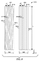
図8において、タイル型キューブコーナー物品810の一部分が模式的に示されている。物品810の2つのタイルのみが示されており、タイルは、図7Aのそれぞれの個々の薄層に対応することができる。このように、薄層801及び802は、それぞれの作用表面811A、811Bを有し、作用表面において、それぞれのキューブコーナー配列が本明細書の教示に従って形成されており、図の乱雑さを低減するために、薄層ごとにこれらの配列から1つの溝セットのみが図中に示されている。薄層は、図示するように、それぞれの伸長された対向する縁部801a、801b、及び802a、802bを有し、それらはまた、伸長したタイルの縁部とみなすことができる。これらの縁部は、薄層の作用表面と主要(側)表面との交差箇所にある。
In FIG. 8, a portion of a tiled
図8は、製造公差内での意図しない変動性、及び/又は2次的な設計上の特徴を提供する目的のための意図的な変動性のいずれにせよ、薄層又はタイルのうち1つ以上の中に、正確な平行からの軽微なずれが存在し得、かかる軽微なずれは、本明細書で検討される設計上の特徴を無効にしないことを説明している。したがって、それぞれの薄層801、802の構造化表面は、溝方向が薄層又はタイルの縁部に平行である、1つの長さ方向の溝、又は長さ方向の溝セットを有するといえる。薄層801において、かかる溝セットは、溝817のセットであり、薄層802において、かかる溝セットは、溝819のセットである。溝ピッチp2を有する溝819は、縁部802a、802bに正確に平行になるように描かれている。対照的に、溝ピッチp1を有する溝817は、正確な平行から軽微なずれを含むように描かれている。溝817は、(図示された場合において)薄層又はタイルの全長Lにわたって、溝ピッチ(p1)に等しい量だけずれている。かかるずれにより、理想的ではないが、いくらかの機能性を保持して縁部に隣接する(それらは断片化されているものの)多くのキューブコーナーが依然としてもたらされる。描画された実施形態において、薄層801の上端及び下端近傍に位置するかかるキューブコーナーに対してより多くの機能性が維持されている。長さLが100mmで、0.2又は0.1mmの溝ピッチp1を有する典型的な薄層の場合、これは、縁部801a、801bのいずれかと、それぞれ約0.11度又は0.057度、すなわち約0.1度以下の溝方向との間の角度のずれに対応する。
FIG. 8 illustrates one of the thin layers or tiles, either unintentional variability within manufacturing tolerances and / or intentional variability for the purpose of providing secondary design features. In the foregoing, there may be minor deviations from exact parallelism, which explains that such minor deviations do not invalidate the design features discussed herein. Thus, it can be said that the structured surface of each
正確に平行な場合でさえ、同様の軽微な平行移動のずれは、薄層又はタイルの縁部に対して溝頂点を配置する際に起こり得る。例えば、薄層802において、溝819の最も左側の溝頂点が、縁部802aと正確に一致するように描かれており、最も右側の溝頂点が、縁部802bと正確に一致するように描かれている。かかる一致からの軽微なずれ、例えば、長さ方向の溝のピッチの30%又は20%又は10%未満の典型的なずれは、本明細書で検討される設計特性を無効にすることなく起こり得る。かかる軽微なずれによりまた、割合WB/p1が正確な整数から、例えば、0.2未満又は0.1未満だけごくわずかにずれ得る。溝頂点を薄層又はタイルの縁部と不正確に位置合わせする場合、縁部は、非常に狭く平坦な、若しくははす縁部によって、又は断片化されたキューブコーナーの非常に狭い細片によって特徴付けられ得る。
Even when precisely parallel, similar minor translational shifts can occur when placing the groove apex relative to the edge of the lamina or tile. For example, in the
我々は、物品の見かけの空間均一性における、タイルの幅W、すなわち、最小の横寸法、及び観察距離Dの効果を説明するために図9を挙げる。人間Pは、距離Dから、再帰反射シート材などのキューブコーナー物品910を観察又は評価する。物品910は、x−y平面内にあるか、又はこれと平行に延在する構造化表面911を有する。構造化表面は、タイル912を含む複数のタイルに配置された別個のキューブコーナー配列を含む。タイルは、y軸などの面内軸に平行に延在してもよく、特徴的な幅Wを有してもよい。人間Pが個々のタイルを観察又は注目する程度は、物品の見かけの空間均一性に直接的な影響を有する。上述したように、隣接するタイル間に同一の又は類似の向きの溝を設けることにより、かつ/又はタイルの特徴的な最小横寸法(幅W)を縮小することにより、空間均一性が向上する。タイルの幅Wを縮小することで、所与の観察距離Dにおける個々のタイルによって範囲が定められる角度が縮小し、これにより見かけの空間均一性を増大させる傾向がある。およそ3〜6メートル(10〜20フィート)よりも近い観察距離Dにおける良好な空間均一性を提供するために、1mm未満、又は0.2〜1mmの範囲内のタイル幅Wを設けることが望ましい。上述のように薄層上にキューブコーナー配列を形成することにより、多くの実施形態においてかかる小さい幅を得ることができる。
We give FIG. 9 to illustrate the effect of tile width W, ie, the minimum lateral dimension, and viewing distance D on the apparent spatial uniformity of the article. From the distance D, the person P observes or evaluates the
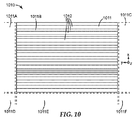
とりわけ、非常に広く、非常に長くてもよい、再帰反射キューブコーナーシート材に関して、タイル張りの複数の段階を使用して、タイル型キューブコーナー物品を製作することができる。かかるキューブコーナー物品の一例を、図10における物品1010として示す。物品1010は、本明細書で検討されるように、複数のタイル1012に配置された別個のキューブコーナー配列を含む構造化表面1011を有する。タイルはそれぞれ、ここではy方向として示される面内方向に沿って伸長している。y方向は、物品1010の製作のダウンウェブ方向に対応してもよく、タイルの大部分又は全ては、溝方向がy方向に平行である1つの長さ方向の溝又は溝セットを有してもよい。
In particular, with respect to retroreflective cube corner sheet material, which may be very wide and very long, tiled cube corner articles can be made using multiple stages of tiling. An example of such a cube corner article is shown as
タイル1012は、複数の薄層、又は他の好適な細片、又は工具の断片においてキューブコーナー配列を形成し、次いで、これらの断片のうち異なるものを群又は束に配置し、最初のタイル型表面を形成することにより製造され得る。かかる群は、構造化表面1011の矩形区域1011Bにおいて示される。例えば、重合体フィルム製造ライン上で製造される再帰反射シート材など、構造化表面がかかる区域よりも大きいことが意図されている物品を製造するために、区域の複数の複製が製造され、互いに並んでレイアップされ得る。かかるプロセスの結果により、隣接する区域1011Aから1011Fを伴う物品1010がもたらされ、かかる区域のそれぞれは、区域1011Bに示されるように個々のタイル1012の同じ配置を有し得る。区域間の境界において、境界の対向する側上に同じ種類のキューブコーナー配列が存在する場合でさえ、キューブコーナー配列は、小さな間隙又は不連続性によって典型的には分断される。
The
図11A及び図11Bにおいて、単一のキューブコーナー配列の再帰反射性能は、配向角の関数として、例示的なタイル型キューブコーナー物品の再帰反射性能と比較されている。図11Aは、単一のキューブコーナー配列のモデル化又は算出された全光反射(TLR)をプロットしている。配列は、57度、57度、及び66度の角度において互いに交差する3つの溝セットから形成されると仮定する。したがって、配列中のキューブコーナーは、(57、57、66)のキューブ形状を有する。これらのキューブは、前方に傾斜し、傾斜平面内に照射角の1次平面を有する。この配列についてのTLRは、物品が屈折率1.5の透明材料から製造されていると仮定して、配向角及び入射角の関数として算出し、その結果を図11Aにプロットした。グラフにおいて、様々な曲線が度単位で入射角と等しい数字で標識されている。したがって、図11a中の曲線0は、照射角0度についてのものであり、同図の曲線10は、照射角10度についてのものであるなどである。グラフを詳しく調べると、単一の配列が0度及び10度の入射角についての配向角の関数として、かなり均一な再帰反射性を提供することを明らかにしている。より大きい入射角、とりわけ20度以上の入射角については、不均一性がだんだんと明らかになっている。
In FIGS. 11A and 11B, the retroreflective performance of a single cube corner array is compared to the retroreflective performance of an exemplary tiled cube corner article as a function of orientation angle. FIG. 11A plots the modeled or calculated total light reflection (TLR) of a single cube corner array. Assume that the array is formed from three groove sets that intersect each other at angles of 57 degrees, 57 degrees, and 66 degrees. Thus, the cube corners in the array have a (57, 57, 66) cube shape. These cubes tilt forward and have a primary plane of illumination angle in the tilt plane. The TLR for this arrangement was calculated as a function of orientation angle and incidence angle, assuming that the article was made from a transparent material with a refractive index of 1.5, and the results were plotted in FIG. 11A. In the graph, various curves are labeled with numbers equal to the angle of incidence in degrees. Accordingly,
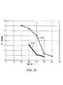
図11Aのキューブコーナー配列といくつかの点で類似のタイル型キューブコーナー物品の再帰反射性能が図11Bに示されている。タイル型物品は、上述の図5及び図6に示したように、3つの対応するタイルに配置された3つの別個のキューブコーナー配列を用いた。したがって、3つのタイルにおけるキューブコーナー配列は、異なる向きの配列であり、それぞれは、溝方向が面内軸に平行である長さ方向の溝セットを含有したが、全てのキューブコーナー配列は、図11Aの単一のキューブコーナー配列と同じキューブ形状(57、57、66)のキューブコーナーを用いた。タイル型物品についてのTLRを、再度、屈折率1.5の透明材料を仮定して、配向角及び入射角の関数として算出し、結果を図11Bにプロットした。図11Aと正に同じように、図11Bにおける様々な曲線は、度単位で入射角と等しい数値で再度標識されている。これら2つの図のグラフを比較することにより、20度及び30度の両方の入射角において、大いに改善された配向均一性が確認でき、更に大きい入射角においてもいくらか改善された配向均一性が確認できる。別のタイル型キューブコーナー物品が検討された。 The retroreflective performance of a tiled cube corner article similar in some respects to the cube corner arrangement of FIG. 11A is shown in FIG. 11B. The tiled article used three separate cube corner arrays arranged in three corresponding tiles as shown in FIGS. 5 and 6 above. Thus, the cube corner arrangements in the three tiles are of different orientations, each containing a lengthwise groove set whose groove direction is parallel to the in-plane axis, but all cube corner arrangements are Cube corners of the same cube shape (57, 57, 66) as the single cube corner array of 11A were used. The TLR for the tile-type article was again calculated as a function of orientation angle and incidence angle, assuming a transparent material with a refractive index of 1.5, and the results were plotted in FIG. 11B. Just as in FIG. 11A, the various curves in FIG. 11B are labeled again with a numerical value equal to the angle of incidence in degrees. By comparing the graphs of these two figures, we can see greatly improved alignment uniformity at both 20 and 30 degree incidence angles, and some improvement in alignment uniformity at larger incidence angles. it can. Another tiled cube corner article was considered.
この物品は、等しい幅の伸長したタイルに配置された正確に3つのキューブコーナー配列を含有すると仮定した限りにおいて、図11Bの物品と類似しており、それぞれの配列について、3つの溝セットのうちの1つは、その溝方向が伸長の面内軸に平行になるように向けられた。しかしながら、それぞれの配列の3つの溝セットは、異なる角度で交差するように製造され、3つの配列は、図11Bのキューブ形状とは異なるキューブ形状、すなわち、(50、62.1、67.9)のキューブ形状の傾斜したキューブコーナーを含有した。3つの配列のそれぞれは、この形状の傾斜したキューブを含有したが、配列中のキューブコーナーは、3つのキューブコーナー配列の異なる方位角の向きにより異なる向きを有した。(50、62.1、67.9)のキューブ形状は、二等辺よりはむしろ不等辺である基部三角形に関連している。改変されたタイル型キューブコーナー物品についてのTLRを、再度、屈折率1.5の透明材料を仮定して、配向角及び入射角の関数として算出した。結果を、図12にプロットする。図11A及び図11Bと正に同じように、図12における様々な曲線は、度単位で入射角と等しい数値で標識されている。この実施形態においては、少なくとも40度の入射角における限りは、図11Bのタイル型物品に対して、配向均一性が更に改善されており、図12のTLRは、配向角の0度から90度の全範囲にわたってより均一である。 This article is similar to the article of FIG. 11B as long as it is assumed that it contains exactly three cube corner arrangements arranged in elongated tiles of equal width, and for each arrangement, of the three groove sets One was oriented so that its groove direction was parallel to the in-plane axis of elongation. However, the three groove sets of each array are manufactured to intersect at different angles, and the three arrays have a cube shape different from that of FIG. 11B, ie (50, 62.1, 67.9). ) Containing cube-shaped inclined cube corners. Each of the three arrays contained inclined cubes of this shape, but the cube corners in the array had different orientations due to the different azimuthal orientations of the three cube corner arrays. The cube shape of (50, 62.1, 67.9) is associated with a base triangle that is unequal rather than isosceles. The TLR for the modified tiled cube corner article was again calculated as a function of orientation angle and incidence angle, assuming a transparent material with a refractive index of 1.5. The results are plotted in FIG. Just as in FIGS. 11A and 11B, the various curves in FIG. 12 are labeled with numerical values equal to the angle of incidence in degrees. In this embodiment, the orientation uniformity is further improved over the tiled article of FIG. 11B as long as at an incident angle of at least 40 degrees, and the TLR of FIG. Is more uniform over the entire range.
図11A、11B、及び12についての結果は、屈折率1.5の透明材料から製造され、上記で説明したような構造化表面を有する、キューブコーナー物品を想定している。屈折率を増加させることにより、一般的に、改善された照射角の区域の幅を広げることができる。例えば、屈折率の増加に伴って、図1A中の改善された照射角の水平区域は、より広くなる(すなわち、垂直方向においてその幅が増加することとなる)。そのため、3つの異なる向きにタイル張りすることにより、屈折率が増すにつれて、向きに関してより均一になる傾向となる。概ね、本明細書で検討される設計上の特徴は、任意の好適な屈折率のキューブコーナー物品に適用することができる。更に、それらの設計上の特徴は、配列中に依存した反射のメカニズム、すわなち、キューブコーナーの小面が反射性の金属(例えば、アルミニウム、銀、ニッケル、若しくはそれらの合金)、若しくは他の好適な材料で覆われているかどうか、又はキューブコーナーの小面が覆われておらず(例えば、空気若しくは真空に露出しており)内部全反射(TIR)現象を用いて光を反射するかどうか、といったことに関わらず、キューブコーナー物品に適用することができる。 The results for FIGS. 11A, 11B, and 12 assume a cube corner article made from a transparent material with a refractive index of 1.5 and having a structured surface as described above. Increasing the refractive index can generally increase the width of the area of improved illumination angle. For example, with increasing refractive index, the horizontal area of improved illumination angle in FIG. 1A becomes wider (ie, its width will increase in the vertical direction). Therefore, tiling in three different orientations tends to become more uniform with respect to orientation as the refractive index increases. In general, the design features discussed herein can be applied to cube corner articles of any suitable refractive index. In addition, their design features include a reflective mechanism that depends on the arrangement, i.e., the metal whose cube corner facets are reflective (eg, aluminum, silver, nickel, or alloys thereof), or others. Whether the cube corner facets are uncovered (eg exposed to air or vacuum) and reflect light using total internal reflection (TIR) phenomenon It can be applied to cube corner articles regardless of whether or not.
これまでの記述では、様々なキューブコーナー要素のキューブ形状、並びにその適合ペア及び配列が言及及び検討されてきた。図13に関連して、明確さのために、我々は、キューブコーナー、並びにその形状及び向きのより系統的な検討を提供する。したがって、我々は、デカルトx−y−z座標系のx−y平面内にある、又はx−y平面に平行に延在する、仮想の構造化表面1311を有する仮想のキューブコーナー物品1310の平面図を図中に提示する。比較及び検討の目的のために、表面1311は、異なる個々のキューブコーナー1320、1330、1340、1350、1360、及び1370を含有して示される。実際には、これらのキューブコーナーのうちの任意の所与の1つは、平行な溝のうち3つの交差するセットから形成される単一のキューブコーナー配列という文脈において所与のタイルの構造化表面上に典型的に存在し、配列は、図13における対象の所与の個々のキューブコーナーと適合ペアを形成するキューブコーナーを含む、他の同一の又は類似のキューブコーナーを含有する。
In the description so far, the cube shapes of various cube corner elements, as well as their matching pairs and arrangements, have been mentioned and discussed. In connection with FIG. 13, for clarity we provide a more systematic review of cube corners and their shape and orientation. Thus, we have the plane of a virtual
図中のそれぞれのキューブコーナーは、(キューブコーナー配列において溝頂点に一致し得る)3つの二面角ではない縁部によって境を限られ、二面角ではない縁部は、基部三角形を形成する。(場合によっては、所与の配列中のキューブコーナーは、認識可能な基部三角形を形成する二面角ではなない3つの縁部を有さなくてもよい。かかる場合、キューブコーナーの小面を平面であるとみなし、次いで、これらの平面と、例えばx−y平面などの構造化表面の平面に平行な基準面との交点によって形成される三角形を検討することによって、基部三角形が依然としてかかるキューブコーナーに関連づけられる。)我々は、キューブコーナーのキューブ形状を、関連する基部三角形の3つの内角によって特徴付け、内角は、基部角度と呼ばれ得る。しかしながら、以下に示すように、それらの3つの基部角度を表現する順番は、重要であり得る。したがって、我々は、基部三角形の内角を特定の順番で列記するという本明細書の目的のために慣例を採用する。すわなち、まず最小の角度を列記し、次いで、残りの角度をかかる最小角度に対して時計周りに(例えば、図13の、図の平面にキューブ頂点が投影されている斜視図など、所与の一貫した平面斜視から基部三角形を見て)列挙する。我々は、結果として得られる角度のセット又は群を、基部角度の順序付きセット、又はより簡単に順序付きセット、若しくは順序付き角度と呼ぶ。基部三角形が2つの角度が3番目よりも小さい二等辺である場合、順序付きセットにおいて、最初の2つの(最小の)基部角度を列記する。この慣例を用いると、図13に示されるキューブコーナーに関連した基部三角形の順序付き角度、すなわち、かかるキューブコーナーのキューブ形状は、以下の通りである。
キューブコーナー1320:(50.8、58.73、70.47)、
キューブコーナー1330:(50.8、58.73、70.47)、
キューブコーナー1340:(50.8、58.73、70.47)、
キューブコーナー1350:(50.8、70.47、58.73)、
キューブコーナー1360:(54.616、54.616、70.768)、及び
キューブコーナー1370:(46.2、66.9、66.9)。
Each cube corner in the figure is bounded by three non-dihedral edges (which may coincide with the groove vertices in the cube corner array), and the non-dihedral edges form a base triangle. . (In some cases, the cube corners in a given array may not have three edges that are not dihedral angles that form a recognizable base triangle. By considering the triangles formed by the intersection of these planes and a reference plane parallel to the plane of the structured surface, such as the xy plane, for example, the base triangle is still such a cube Associated with a corner.) We characterize the cube shape of a cube corner by the three interior angles of the associated base triangle, which may be referred to as the base angle. However, as will be shown below, the order in which those three base angles are represented can be important. We therefore adopt the convention for the purposes of this specification of listing the interior angles of the base triangles in a particular order. That is, the minimum angle is listed first, and then the remaining angle is clockwise with respect to such minimum angle (eg, a perspective view with the cube vertices projected onto the plane of the diagram in FIG. 13). Enumerate (see base triangle from given consistent plane perspective). We refer to the resulting set or group of angles as an ordered set of base angles, or more simply an ordered set, or ordered angle. If the base triangle is isosceles with two angles less than the third, list the first two (minimum) base angles in the ordered set. Using this convention, the ordered angle of the base triangle associated with the cube corner shown in FIG. 13, ie the cube shape of such cube corner, is as follows:
Cube corner 1320: (50.8, 58.73, 70.47),
Cube corner 1330: (50.8, 58.73, 70.47),
Cube corner 1340: (50.8, 58.73, 70.47),
Cube corner 1350: (50.8, 70.47, 58.73),
Cube corner 1360: (54.616, 54.616, 70.768), and cube corner 1370: (46.2, 66.9, 66.9).
これらのキューブコーナーのそれぞれは、傾斜し、すわなち、その光学軸は、構造化表面の平面に直交していない。したがって、光学軸は、z軸に対して傾いており、z軸に平行ではない。傾斜形状は、キューブコーナーに対する(かつそれが一部であってもよい配列に対する)傾斜平面を画定し、傾斜平面は、キューブコーナーの光学軸、及び構造化表面の法線方向、すなわちz軸を含有する。図13におけるキューブコーナーごとの傾斜平面は、太い黒色矢印を参照して特定され、矢印は、所与のキューブコーナーの光学軸の、x−y平面上への投影を表す。したがって、例えば、キューブコーナー1320は、その光学軸の投影を表す太い黒色矢印を有するように示され、x−y平面に垂直で太い黒色矢印を含有する平面は、かかるキューブコーナー1320の傾斜平面を表す。傾斜平面は、基部三角形の任意の側に垂直ではないので、キューブコーナー1320、1330、1340、及び1350は、片側に傾いて傾斜しているといえる。キューブコーナー1360は、前方に傾斜しているといえる。キューブコーナー1370は、後方に傾斜しているといえる。
Each of these cube corners is inclined, that is, its optical axis is not orthogonal to the plane of the structured surface. Therefore, the optical axis is inclined with respect to the z-axis and is not parallel to the z-axis. The sloping shape defines a sloping plane relative to the cube corner (and to an array that it may be part of) that is defined by the cube corner optical axis and the normal direction of the structured surface, ie the z-axis. contains. The inclined plane for each cube corner in FIG. 13 is identified with reference to a thick black arrow, which represents the projection of the optical axis of a given cube corner onto the xy plane. Thus, for example, a
傾斜形状はまた、上述したように、それぞれのキューブコーナーに(かつそれが一部であってもよい配列に)照射角の1次平面を提供する。図13に示されるキューブコーナーのそれぞれについて、照射角の(複数の)1次平面が算出され、かかる(複数の)平面の方向は、図13において、対応するキューブコーナー上に重なり合った1本の点線又は複数の点線によって示されている。したがって、例えば、キューブコーナー1320、1330、1340、及び1350はそれぞれ、1つのみの照射角の1次平面を有し、これらの場合のそれぞれにおいて、この平面は、キューブコーナーの傾斜平面と平行ではない。キューブコーナー1360は、1つのみの照射角の1次平面を有し、それは、傾斜平面に平行である。キューブコーナー1370は、2つの照射角の1次平面を有し、それらのいずれも傾斜平面に平行ではない。
The slanted shape also provides a primary plane of illumination angle at each cube corner (and in an array it may be part of) as described above. For each of the cube corners shown in FIG. 13, the primary plane (s) of the illumination angle are calculated, and the direction of the plane (s) is the one that overlaps the corresponding cube corner in FIG. It is indicated by a dotted line or a plurality of dotted lines. Thus, for example,
キューブコーナー1320、1330、及び1340の順序付けられた基部角度のセットは、互いに等しいので、キューブコーナー1320、1330、及び1340は全て、同じキューブ形状を有する。これらのキューブコーナーのうち、キューブコーナー1320及び1330はまた、それらが異なるキューブ寸法及び異なるキューブ高さを有するという事実にも関わらず、同じキューブの向きを有する。キューブコーナー1320及び1340は、同じキューブ寸法及び高さを有するが、それぞれの傾斜平面は互いに平行ではないので、異なる向きを有する。
Since the ordered base angle set of
キューブコーナー1320及び1360は、順序付け基部角度の異なるセットを伴う、異なるキューブ形状を有するが、それぞれの傾斜平面が互いに平行である場合、それらは同じ向きを有し得る。
キューブコーナー1320及び1350は、同じキューブ寸法及び高さを有するが、異なるキューブ形状を有する。これらのキューブコーナーのそれぞれが、50.8度の1つの基部角度、58.73度の別の基部角度、及び70.47度の別の基部角度を有しても、すわなち、1つのキューブコーナー要素の基部三角形における全ての基部角度が、他のキューブコーナー要素の基部三角形においても見られても、それらはやはり、異なるキューブ形状を有する。図を詳しく調べることによって、並びに一致しない順序付け基部角度のそれぞれのセットを比較することによって、異なるキューブ形状が見られる。なお、キューブコーナー1320を、その傾斜平面がキューブコーナー1350についての傾斜平面に平行になるように、方位角上に(z軸を中心に)回転する場合、これらのキューブコーナーについての、それぞれの照射角の1次平面は、互いに平行ではなくなるであろうことに留意されたい。したがって、キューブコーナー1320のキューブ形状(50.8、58.73、70.47)は、キューブコーナー1350のキューブ形状(50.8、70.47、58.73)とは異なる。
キューブコーナー1320とキューブコーナー1350との間の特有の関係は、1つのキューブコーナー(又は、かかるキューブコーナーの配列)についての、基部角度の順序付きセットが、他のキューブコーナー(又は、かかる他のキューブコーナーの配列)についての、基部角度の順序付きセットの並べ替えであることに注目することによって、表現することができる。例えば、順序付きセット(50.8、70.47、58.73)は、順序付きセット(50.8、58.73、70.47)の並べ替えである。なぜなら、上記の「順序付きセット」という用語の記述に準拠する限りは、これらの順序付きセットが、同じ角度を、異なる順序で包含しているからである。この関係を有するキューブコーナーの配列は、少なくとも、平行な溝の3つの交差するセットによってそれらのキューブコーナーが形成される場合、同じ溝角度を有し、切削工具の単一のセットで形成することができる。別の言い方をすると、3つのダイヤモンド切削工具を用いて、キューブコーナー1320のようなキューブの配列を形成するために必要な、平行な溝の3つのセットを形成してもよく、キューブコーナー1350は、キューブコーナー1320とは異なるキューブ形状を有しても、(異なる順序で用いられる場合、)これらの同じ3つのダイヤモンド切削工具を用いて、キューブコーナー1350のようなキューブの配列を形成するのに必要な平行な溝の3つのセットを形成することができる。この関係を利用して、我々は、キューブコーナー物品の別々のタイルにおける6つもの別個のキューブコーナー配列を提供することができ、それぞれの配列は、異なる向きを有し、それぞれの配列は、溝方向が所与の面内軸と平行な長さ方向の溝を有し、これらの配列の全ては、3つの溝切削工具の単一のセットで製造することができる。かかる実施形態は、図14に示されている。
The unique relationship between
図14において、キューブコーナー物品1410が、概略上面図又は概略平面図で示されている。物品1410は、再帰反射シート材、又はその製造に関連した工具であってもよい。物品1410は、A、B、C、D、E、Fと標識された6つの隣接するタイルの積み重ねに配置された、6つの別個のキューブコーナー配列を伴う構造化表面1411を有する。タイルは面内y軸に平行に伸長し、それぞれのタイルはy軸にまた平行である対向する伸長した縁部を有する。代替の実施形態では、タイルは、y軸に沿って伸長する必要はなく、かつ/又はy軸に平行な縁部を有する必要はない。それぞれのタイルは、平行な溝の3つの交差するセットによって形成された傾斜したキューブコーナー要素のうち1つの配列を有する。タイルごとに、その3つの溝セットのうちの1つは、溝方向がy軸に平行である長さ方向の溝のセットである。それぞれのタイルはまた、タイルの伸長した縁部において、断片化されたキューブコーナーが実質的に無いように、長さ方向の溝の長さ方向の溝ピッチの整数倍に等しいタイル幅(x方向に測定)を有する。タイル幅は、一様ではない。タイルA及びDは、互いに等しいが、タイルB、C、E、及びFのタイル幅よりも広いタイル幅を有し、タイルB、C、E、及びFのタイル幅もまた互いに等しい。
In FIG. 14, a
図における参照の目的のために、キューブコーナーの1つの拡大された適合ペアは、それぞれのタイルの右手側に示される。いかなる場合も、拡大された適合ペアは、関連するキューブコーナー配列におけるキューブコーナー要素の適合ペアを表している。図13と類似の様式で、キューブコーナーの光学軸のx−y平面内の投影を示すために、それぞれの拡大された適合ペアにおいて太い黒色矢印が含まれている。したがって、これらの太い黒色矢印は、配列ごとの傾斜平面の方向の指示を提供する。図12を踏まえて、適合ペア及びその関連した配列について、照射角の1次平面の方向を示すために、図14のそれぞれの拡大された適合ペア上に点線が重ね合わせられている。 For reference purposes in the figure, one expanded matched pair of cube corners is shown on the right hand side of each tile. In any case, the expanded matched pair represents a matched pair of cube corner elements in the associated cube corner array. In a manner similar to FIG. 13, a thick black arrow is included in each enlarged matched pair to show the projection in the xy plane of the cube corner optical axis. Thus, these thick black arrows provide an indication of the direction of the inclined plane for each array. In view of FIG. 12, a dotted line is superimposed on each enlarged matched pair in FIG. 14 to show the direction of the primary plane of the illumination angle for the matched pair and its associated arrangement.
タイルA、B、及びCのキューブコーナーは全て、(49、61、70)のキューブ形状を有する。タイルD、E、及びFのキューブコーナーは全て、(49、70、61)のキューブ形状を有する。したがって、タイルA、B、又はCのうち任意の1つのキューブコーナーについての基部角度の順序付きセットは、タイルD、E、及びFのうち任意の1つのキューブコーナーについての基部角度の順序付きセットの並べ替えであり、逆も同様である。更に、3つのダイヤモンド切削工具の1つのセットを用いて、タイルA、B、C、D、E、及びFの全てについてのキューブの配列を形成するために必要な平行な溝の3つのセットを形成することができる。 The cube corners of tiles A, B, and C all have a (49, 61, 70) cube shape. The cube corners of tiles D, E, and F all have a (49, 70, 61) cube shape. Thus, the ordered set of base angles for any one cube corner of tiles A, B, or C is the ordered set of base angles for any one cube corner of tiles D, E, and F. Is the rearrangement and vice versa. In addition, using one set of three diamond cutting tools, three sets of parallel grooves needed to form an array of cubes for all of tiles A, B, C, D, E, and F Can be formed.
複合溝は、図14においては標識されていないが、図中に容易に見られる。1つの複合溝は、タイルA及びBの境界において現れ、別の複合溝は、タイルB及びCの境界において現れ、別の複合溝は、タイルC及びDの境界において現れ、別の複合溝は、タイルD及びEの境界において現れ、別の複合溝は、タイルE及びFの境界において現れる。それぞれの場合において、これらの複合溝は、y軸に平行であり、所与の複合溝に隣接するそれぞれのタイルにおける溝セットの溝方向に平行である。更に、それぞれの場合において、複合溝は、所与の複合溝の境を限る2つのタイルのそれぞれにおける長さ方向の溝の溝角度とは異なる溝角度を有する。 The composite groove is not labeled in FIG. 14, but is easily seen in the figure. One composite groove appears at the boundary of tiles A and B, another composite groove appears at the boundary of tiles B and C, another composite groove appears at the boundary of tiles C and D, and another composite groove is , Appear at the boundaries of tiles D and E, and another composite groove appears at the boundaries of tiles E and F. In each case, these composite grooves are parallel to the y-axis and parallel to the groove direction of the groove set in each tile adjacent to a given composite groove. Further, in each case, the composite groove has a groove angle that is different from the groove angle of the longitudinal groove in each of the two tiles that delimits a given composite groove.
キューブコーナー物品1410には、多くの改変を行うことが可能である。タイルの幅及び形状を変更することができる。タイルは、異なる順序で再配置されてもよい。物品1410に存在するタイルのうち1つ以上を除去してもよく、1つ以上の傾斜していないキューブコーナー配列と同様に1つ以上の傾斜したキューブコーナー配列を含む、異なるキューブコーナー配列を有する1つ以上のタイルが、挿入され、ないしは別の方法で追加されてもよい。かかる改変において、少なくとも2つのタイルは、キューブ形状は同一だが、向きが異なるキューブコーナー配列を有してもよく、少なくとも2つのタイルは、基部角度のセットが並べ替えによって関連づいているキューブを有してもよい。平行な溝のセットについての異なる交差角度、及びキューブコーナーについての対応する異なる基部角度が用いられてもよい。所与の溝セットにおける溝の溝深さは、全て同じでもよく、又は全て互いに異なっていてもよく、又は幾つかは同じでありいくつかは異なっていてもよい。あるいは又は加えて、第1の溝セットにおいて用いられる(複数の)溝深さは、第1の溝セットと交差する第2の溝セットにおいて用いられる(複数の)溝深さと同じであってもよく、又は異なっていてもよい。
Many modifications can be made to the
図15では、図14のタイルA、B、C、D、E、Fのそれぞれからの1つのキューブコーナーが、キューブ形状及び面内y軸に対する向きを維持しながら再現及び拡大されている。簡略化のために、図14のタイルAからのキューブコーナーは、図15においてAと標識され、図14のタイルBからのキューブコーナーは、図15においてBと標識されるなどである。この図において、光学軸のx−y平面内の投影を表す太い黒色矢印、並びに照射角の1次平面を表す点線を、図14においてよりもより容易に見ることができる。 In FIG. 15, one cube corner from each of the tiles A, B, C, D, E, and F of FIG. 14 is reproduced and enlarged while maintaining the cube shape and orientation with respect to the in-plane y-axis. For simplicity, the cube corner from tile A in FIG. 14 is labeled A in FIG. 15, the cube corner from tile B in FIG. 14 is labeled B in FIG. In this figure, a thick black arrow representing the projection of the optical axis in the xy plane and a dotted line representing the primary plane of the illumination angle can be seen more easily than in FIG.
図16において、図14のタイルA、B、C、D、E、Fの全てについての、したがってまた、図15のキューブコーナーA、B、C、D、E、Fの全てについての、傾斜平面及び照射角の1次平面が、x軸及びy軸に関して互いに重ね合わされて図示されており、これらの軸は、図14及び図15においてと同じ意味を有する。キューブコーナー配列(及び対応するタイル)ごとに、図16における実線は、傾斜平面及びx軸及びy軸に関するその向きを表し、図16における点線は、照射角の1次平面及び同じx軸及びy軸に関するその向きを表す。これらの実線及び点線は、簡略化のために、図14及び図15で用いられる同じ標識に対応し、A、B、C、D、E、Fの文字で標識されている。例えば、図14のタイルA及び図15のキューブAは、図16において実線Aによって表わされる傾斜平面と、図16において点線Aで表わされる照射角の1次平面と、を有する。したがって、図16における様々な傾斜平面及び照射角の1次平面は、タイル型キューブコーナー物品1410及びその構成部品(タイル)を表す。図16の実線及び点線の長さは、任意であるが、実線は、均一な長さの点線よりも長い、均一な長さを有するように描かれ、そのため読者は、より簡単に両者の区別がつけられる。図16を詳しく調べることで、物品1410は、物品の構成要素である照射角の1次平面が物品の構成要素である傾斜平面よりも、方位角においてより均等に分布するように構成されていることが明らかになる。
In FIG. 16, inclined planes for all of the tiles A, B, C, D, E, F of FIG. 14 and therefore also for all of the cube corners A, B, C, D, E, F of FIG. And the primary plane of the illumination angle are shown superimposed on each other with respect to the x-axis and the y-axis, and these axes have the same meaning as in FIGS. For each cube corner array (and corresponding tile), the solid line in FIG. 16 represents the tilt plane and its orientation with respect to the x and y axes, and the dotted line in FIG. 16 represents the primary plane of the illumination angle and the same x axis and y. Represents its orientation with respect to the axis. These solid and dotted lines correspond to the same signs used in FIGS. 14 and 15 for simplicity and are labeled with the letters A, B, C, D, E, F. For example, the tile A in FIG. 14 and the cube A in FIG. 15 have an inclined plane represented by a solid line A in FIG. 16 and a primary plane of an irradiation angle represented by a dotted line A in FIG. Accordingly, the various inclined planes and the primary plane of the illumination angle in FIG. 16 represent the tiled
物品1410のうち2つを単純に結合することにより製造された物品については、二重の傾斜平面及び二重の照射角の1次平面が図16のような表現で表されるであろう。かかる平面を重複して数えることを避けるために、我々は、より一般的に、複数のタイルについての照射角の1次平面の特有のものが、傾斜平面の特有のものよりも方位角中においてより均等に分布しているように、タイル型キューブコーナー物品は構成されると規定する。「方位角においてより均等に分布している」という概念を定量化するために、我々は、照射角の1次平面の特有のもの同士の間の最小の角度分離として角度PhiMin1を定義することができ、かつ、傾斜平面の特有のもの同士の間の最小の角度分離としてPhiMin2を定義することができる。図16において、PhiMin1は、18.00度であり、PhiMin2は、2.23度である。我々はまた、照射角の1次平面の特有のもの同士の間の最大の角度分離として角度PhiMax1を定義してもよく、傾斜平面の特有のものの最大の角度分離としてPhiMax2を定義してもよい。図16において、PhiMax1は、52.00度であり、PhiMax2は、58.77度である。我々は、照射角の1次平面の特有のもの同士の間の平均角度分離として角度PhiAvg1を更に定義してもよく、傾斜平面の特有のもの同士の間の平均角度分離としてPhiAvg2を定義してもよい。図16において、PhiAvg1とPhiAvg2とは、同じであり、それぞれは、30.00度に等しい。我々は、PhiAvg/(PhiMax−PhiMin)に等しい角度分布メトリック(「PhiADM」)を定義することができる。図16において、照射角の1次平面についての角度分布メトリックは、PhiADM1=0.882であり、傾斜平面についての角度分布メトリックは、PhiADM2=0.531である。したがって、「方位角においてより均等に分布している」という概念を定量化するために、我々は、以下の関係の任意の1つ、又は幾つか(任意の2つ以上の任意の組み合わせ)、又は全てを指定することができる。
・PhiMin1>PhiMin2
・PhiMin1≧2*PhiMin2
・PhiMax1<PhiMax2
・PhiADM1>PhiADM2
For an article made by simply joining two of the
・ PhiMin1> PhiMin2
・ PhiMin1 ≧ 2 * PhiMin2
・ PhiMax1 <PhiMax2
・ PhiADM1> PhiADM2
図14に示したものに基づいて、幾つかのキューブコーナー物品をモデル化した。第1の場合、モデルは、上述した同じキューブ形状、すわなち、タイルA、B、及びCについては(49、61、70)を、タイルD、E、及びFについては(49、70、61)を、想定した。モデルは、先の米国特許第4,775,219号のAppeldornの特許に関して、上述したように、投射光の方向からわずかに光を分散させるために、キューブコーナーが2次的な設計上の特徴を有すると更に仮定した。2次的な設計上の特徴は、正確に90度のキューブコーナーの小面同士の間の二面角を生成するであろう溝角度とは、溝角度がごくわずかに異なり、この溝角度の差は、正確な直交性を生成する名目上の向きに対して、弧の2分(0.033度)だけずれたキューブコーナーの小面に等しいと仮定した。モデルは、6つのキューブコーナー配列のそれぞれについて個別に、キューブコーナー物品は屈折率1.586の透明なポリカーボネートからなると仮定して、かつキューブコーナーは空気に露出されており内部全反射によって光を反射すると仮定して、初めに全光反射(TLR)を算出した。TLRは、一連の異なる入射角に対する配向角の関数として算出された。次いで、モデルは、配向角と入射角との組み合わせ毎に、6つの配列に対するTLRの加重平均を算出した。タイルB、C、E、及びFの配列については、15%の重み値が用いられ、タイルA及びDの配列については、20%の重み値が用いられた。これらの重み値は、タイル型物品1410におけるそれぞれのタイルの、相対的な幅、及び相対的な表面積に比例している。
Several cube corner articles were modeled based on those shown in FIG. In the first case, the model is the same cube shape as described above, ie (49, 61, 70) for tiles A, B, and C, (49, 70, for tiles D, E, and F). 61) was assumed. The model is a secondary design feature where the cube corner is a secondary design to slightly disperse the light from the direction of the projected light, as described above with respect to the Appelldon patent in the previous US Pat. No. 4,775,219. It was further assumed that A secondary design feature is that the groove angle is very slightly different from the groove angle that would produce a dihedral angle between the facets of a cube corner of exactly 90 degrees. The difference was assumed to be equal to the facet of the cube corner, offset by 2 minutes (0.033 degrees) of the arc, with respect to the nominal orientation producing the correct orthogonality. The model assumes that for each of the six cube corner arrays individually, the cube corner article is made of transparent polycarbonate with a refractive index of 1.586, and the cube corner is exposed to air and reflects light by total internal reflection. Assuming that, total light reflection (TLR) was first calculated. The TLR was calculated as a function of the orientation angle for a series of different incident angles. The model then calculated a weighted average of TLRs for the six arrays for each combination of orientation angle and incident angle. For the arrangement of tiles B, C, E, and F, a weight value of 15% was used, and for the arrangement of tiles A and D, a weight value of 20% was used. These weight values are proportional to the relative width and relative surface area of each tile in the
結果として得られる、算出されたタイル型再帰反射物品の再帰反射性能は、図17の等強度プロットにおいて示されている。図において、算出されたTLRの大きさは、半径方向にあり、配向角は、方位角方向にある。0度〜70度までの10度きざみで、入射角についての曲線がプロットされており、曲線1700は、0度の入射角を表し、曲線1710は、10度の入射角を表し、曲線1720は、20度の照射角を表すなどである。次いで、第2のタイル型キューブコーナー物品がモデル化された。物品は、屈折率が、1.586ではなく1.50であると仮定したことを除いて、図17の物品と同じであると仮定した。この改変に伴って、タイル型物品のTLRを、図17に関連して上記で記載したのと同じ方法で算出した。結果として得られる算出された再帰反射性能が、図17と同じフォーマットを有する図18の等強度プロットにおいて示されている。0度〜60度までの10度きざみで、入射角についての曲線がプロットされており、曲線1800は、0度の入射角を表し、曲線1810は、10度の入射角を表し、曲線1820は、20度の照射角を表すなどである。これらの曲線と図17の対応する曲線との間には、いくらかの差異を見ることができる。かかる差異は、キューブコーナー物品の屈折率における変化の影響を例証するものである。
The resulting retroreflective performance of the calculated tiled retroreflective article is shown in the isointensity plot of FIG. In the figure, the calculated TLR size is in the radial direction, and the orientation angle is in the azimuth direction. Curves for incident angles are plotted in increments of 10 degrees from 0 degrees to 70 degrees,
比較の目的のために、我々はまた、上記の図3に示され、先の米国特許出願公開第2011/0013281号(Mimuraら)の刊行物で検討されているキューブコーナー物品について調査した。図19は、先の米国特許出願公開第2011/0013281号(Mimuraら)の刊行物における図の再現であり、この刊行物は、キューブコーナー314−1及び315−1が順序付けられた基部角度(54.918、66.659、58.423)を有し、キューブコーナー314−2及び315−2が順序付けられた基部角度(54.918、58.423、66.659)を有する実施形態に関連しており、この実施形態を、以後はMimuraの実施形態と呼ぶ。図19のグラフは、光学シミュレーションを用いて算出され、この実施形態の再帰反射性能であるといえる。グラフは、配向角を15度ずつ増やしてプロットしたデータポイントを有する、5度の入射角(曲線1905)、15度(曲線1915)、30度(曲線1930)における性能を示している。 For comparative purposes, we also investigated the cube corner article shown in FIG. 3 above and discussed in a previous US Patent Application Publication No. 2011/0013281 (Mimura et al.) Publication. FIG. 19 is a reproduction of the figure in a previous publication of US Patent Application Publication No. 2011/0013281 (Mimura et al.), Which is based on the base angle (ordered by cube corners 314-1 and 315-1). 54.918, 66.659, 58.423) and cube corners 314-2 and 315-2 are related to embodiments having ordered base angles (54.918, 58.423, 66.659) This embodiment is hereinafter referred to as Mimura embodiment. The graph of FIG. 19 is calculated using optical simulation, and can be said to be the retroreflection performance of this embodiment. The graph shows performance at 5 degrees incident angle (curve 1905), 15 degrees (curve 1915), and 30 degrees (curve 1930) with data points plotted with increasing orientation angles by 15 degrees.
我々は、30度よりも大きい入射角におけるMimuraの実施形態の再帰反射性能を判定するために、Mimuraの結果を再現することを試みた。この取組みにおける1つの障害は、先の米国特許出願公開第2011/0013281号(Mimuraら)の刊行物における、その実施形態について仮定されている屈折率に関する情報の欠如である。我々自身の光学モデル化ソフトウェアを用いて、我々は、ソフトウェアにMimuraの実施形態についてのキューブコーナー形状の情報を入力し、多数の異なる屈折率に対する5度、15度、30度の入射角における実施形態のTLRの等強度プロットを生成した。次いで、我々は、図19の曲線と、とりわけ30度の入射角における曲線1930と、最もよく合致する曲線を生成する屈折率を特定した。この処置は、屈折率が1.586か、又は1.586に略等しいことを示した。図20は、1.586の屈折率を仮定して、Mimuraの実施形態対して我々の光学モデル化ソフトウェアによって算出されたTLRを用いた等強度プロットを示す。グラフは、図19と正に同様に配向角を15度ずつ増やしてプロットされたデータポイントを伴って、5度の入射角(曲線2005)、15度(曲線2015)、30度(曲線2030)、40度(曲線2040)、及び50度(曲線2050)における性能を示す。曲線2030は、図19における曲線1930によく近似することが判る。図20、とりわけ、その曲線2040及び2050を詳しく調べると、増加した入射角におけるMimuraの実施形態について、配向角の関数としての均一性は急速に低下することが明らかになる。
We have attempted to reproduce the Mimura results to determine the retroreflective performance of Mimura embodiments at angles of incidence greater than 30 degrees. One obstacle to this approach is the lack of information regarding the refractive index assumed for that embodiment in the publication of the previous US Patent Application Publication No. 2011/0013281 (Mimura et al.). Using our own optical modeling software, we enter the cube corner shape information for the Mimura embodiment into the software and perform at 5 °, 15 ° and 30 ° incidence angles for a number of different refractive indices. An isointensity plot of the morphological TLR was generated. We then identified the refractive index that produced the curve that best matched the curve of FIG. 19, and in particular the
上述した均一性指数UIを、Mimuraの実施形態について、屈折率1.586を仮定して算出し、同じ屈折率を有する図17の実施形態(図14、15、及び16も参照のこと)について算出した。結果を図21に示す。この図において、曲線2101は、Mimuraの実施形態についてのUIであり、曲線2102は、図17の実施形態についてのものである。
The uniformity index UI described above is calculated for the Mimura embodiment, assuming a refractive index of 1.586, and for the embodiment of FIG. 17 (see also FIGS. 14, 15 and 16) having the same refractive index. Calculated. The results are shown in FIG. In this figure,
再帰反射キューブコーナー物品を形成するための例示的な材料として、例えば、ポリ(カーボネート)、ポリ(メチルメタクリレート)、ポリ(エチレンテレフタレート)、脂肪族ポリウレタン、並びにエチレンコポリマー及びそのイオノマー、並びにその混合物などの熱可塑性ポリマーが挙げられるが、これに限定はされない。キューブコーナーシート材は、米国特許第5,691,846号(Benson、Jr.ら)に記載されているものなどフィルム上に直接鋳造することによって調製されてもよい。放射線硬化キューブコーナーのためのポリマーとして、多官能アクリレート又はエポキシ、単官能及び多官能のモノマーと配合されたアクリレート化ウレタン、及び本明細書に参照により援用される米国特許第7,8621,87号(Thakkarら)に記載されているような、窒素含有ポリマーなどの架橋アクリレートが挙げられる。更に、前述されたようなキューブコーナーは、より可撓性がある鋳造物キューブコーナーシート材を得るために、軟質ポリ塩化ビニルのフィルム上に鋳造されてもよい。これらのポリマーは、熱安定性、環境安定性、透明性、工具又は型からの優れた剥離性、及びキューブコーナーの小面への反射性コーティングの適用能力を含む、1つ以上の理由のために望ましい。 Exemplary materials for forming retroreflective cube corner articles include, for example, poly (carbonate), poly (methyl methacrylate), poly (ethylene terephthalate), aliphatic polyurethane, and ethylene copolymers and their ionomers, and mixtures thereof. Although not limited to these thermoplastic polymers. Cube corner sheet material may be prepared by casting directly onto a film, such as that described in US Pat. No. 5,691,846 (Benson, Jr. et al.). Polymers for radiation-cured cube corners, polyfunctional acrylates or epoxies, acrylated urethanes blended with monofunctional and polyfunctional monomers, and US Pat. No. 7,862,87, incorporated herein by reference. And cross-linked acrylates such as nitrogen-containing polymers as described in (Takkar et al.). Further, cube corners as described above may be cast on soft polyvinyl chloride film to obtain a more flexible cast cube corner sheet material. These polymers are for one or more reasons, including thermal stability, environmental stability, transparency, excellent release from tools or molds, and the ability to apply a reflective coating to the facets of cube corners. Is desirable.
鏡面反射コーティング又は反射層は、再帰反射を促すために、キューブコーナー要素の小面上に(例えば、キューブコーナーフィルムの裏側に)配置されてもよい。好適な反射コーティングとして、アルミニウム、銀、ニッケル、又はこれらの合金などの、金属コーティングが挙げられ、コーティングは、蒸着又は化学蒸着などの既知の手法によって塗布されてもよい。反射層はまた、多層の光学フィルムであってもよく、又はそれを含んでもよい。反射コーティング又は反射層の接着を促すために、キューブコーナーの小面にプライマー層を塗布してもよい。キューブコーナーの小面に反射コーティング又は反射層が何ら用いられない場合には、キューブコーナーの小面は、空気又は真空にさらされ、封止フィルムを用いて、空気界面を維持して、水、汚れ等を締め出す封止セル又はポケットを設けてもよい。再帰反射物品のための例示的な封止フィルムは、米国特許第7,611,251号(Thakkarら)に開示されている。他の実施形態では、例えば、米国特許出願公開第2013/0034682号(Freeら)において開示されているように、バリア材を含む感圧接着層がキューブコーナー上に配設されてもよい。 A specular reflective coating or reflective layer may be placed on the facet of the cube corner element (eg, on the back side of the cube corner film) to facilitate retroreflection. Suitable reflective coatings include metal coatings such as aluminum, silver, nickel, or alloys thereof, and the coating may be applied by known techniques such as vapor deposition or chemical vapor deposition. The reflective layer may also be or include a multilayer optical film. A primer layer may be applied to the facets of the cube corners to promote adhesion of the reflective coating or reflective layer. If no reflective coating or layer is used on the cube corner facet, the cube corner facet is exposed to air or vacuum, and the sealing film is used to maintain the air interface, You may provide the sealing cell or pocket which keeps dirt off. Exemplary sealing films for retroreflective articles are disclosed in US Pat. No. 7,611,251 (Thakkar et al.). In other embodiments, a pressure sensitive adhesive layer comprising a barrier material may be disposed on the cube corner, as disclosed, for example, in US 2013/0034682 (Free et al.).
プリズム状再帰反射シート材は、例えば、予備形成されたシートを(複数の)キューブコーナー配列を含有する構造化表面で型押しすることにより、又は流体材料を好適な成形型に注型成形することにより、一体型の材料として製造されてもよい。あるいは、再帰反射シート材は、予備形成されたフィルムに対してキューブコーナー要素を鋳造することにより、又は予備形成されたキューブコーナー要素に予備形成されたフィルムを積層することによって、層状の製品として製造されてもよい。キューブコーナー要素は、約1.59の屈折率を有する厚みがおよそ0.5mmのポリカーボネートフィルム上に形成されてもよい。再帰反射シート材を製造するために有用な材料は、寸法安定性、耐久性、耐候性があり、かつ所望の構成へ容易に成形可能である材料である。典型的に熱及び圧力の下で成形可能である、光学的に透過型の任意の材料を概ね用いることができる。シート材はまた、所望により、着色料、染料、UV吸収材、又は分離したUV吸収層、及び他の添加物を含むことができる。 Prism-like retroreflective sheeting can be, for example, by stamping a pre-formed sheet with a structured surface containing cube corner array (s) or casting a fluid material into a suitable mold. Thus, it may be manufactured as an integral material. Alternatively, the retroreflective sheeting is manufactured as a layered product by casting cube corner elements against the preformed film or by laminating the preformed film on the preformed cube corner elements. May be. The cube corner element may be formed on a polycarbonate film having a refractive index of about 1.59 and a thickness of approximately 0.5 mm. Materials useful for producing retroreflective sheeting are materials that have dimensional stability, durability, weather resistance, and can be easily molded into the desired configuration. Any optically transmissive material that is typically moldable under heat and pressure can be used. The sheet material can also optionally include colorants, dyes, UV absorbers, or separate UV absorbing layers, and other additives.
別途記載のない限り、本明細書及び「特許請求の範囲」において使用される量、諸特性の測定値などを表す全ての数は、「約」なる語によって修飾されているものとして理解されるべきである。したがって、反することが示されない限り、本明細書及び「特許請求の範囲」に記載の数値的パラメータは、本願の教示を利用して当業者により得ることが求められる所望の性質に応じて変化する近似値である。特許請求の範囲に対する均等論の適用を制限しようとするものではないが、それぞれの数値パラメータは、少なくとも記載される有効桁数を考慮し、更に一般的な四捨五入法を適用することによって解釈されるべきである。本発明の広義の範囲を示す数値的範囲及びパラメータは近似的な値ではあるが、任意の数値が本明細書に述べられる具体例に記載される限りにおいて、これらは妥当な程度に可能な範囲で正確に記載されるものである。しかしながら、いかなる数値も、試験又は測定の限界に伴う誤差を含み得る。同様に、「等しい」、「平行」、「一致する」などの用語は、本明細書で用いられる場合、正確な等しさ、平行、一致等からの偏りが、製造公差の範囲内である、又はさもなければ、本明細書の他の箇所で記載されるように2次的な設計上の特徴のためにかかる正確さから外れている実施形態を包含すると、理解されるべきである。 Unless otherwise stated, all numbers representing amounts, measurements of properties, etc. used in the specification and in the claims are understood to be modified by the word “about”. Should. Accordingly, unless indicated to the contrary, the numerical parameters set forth herein and in the claims vary depending on the desired properties sought to be obtained by one of ordinary skill in the art using the teachings herein. It is an approximate value. Although not intended to limit the application of the doctrine of equivalents to the claims, each numeric parameter is interpreted by taking into account at least the significant digits listed and applying a more general rounding method Should. The numerical ranges and parameters indicating the broad scope of the present invention are approximate values, but as long as any numerical value is described in the specific examples described herein, these are to the extent possible. Is exactly what is described. However, any numerical value may include errors associated with test or measurement limits. Similarly, terms such as “equal”, “parallel”, “match”, etc., as used herein, deviations from exact equality, parallel, match, etc., are within manufacturing tolerances. Or otherwise, it should be understood to encompass embodiments that deviate from such accuracy due to secondary design features as described elsewhere herein.
当業者には、本発明の趣旨及び範囲から逸脱することなく本発明の様々な改変及び変更を行い得ることは明らかであり、本発明は本明細書に記載される例示的な実施形態に限定されない点は理解されるべきである。読者は、1つの開示される実施形態の特徴は、別途記載のない限り他の全ての開示される実施形態にも適用することが可能であると仮定すべきである。本明細書において参照される、米国特許、特許出願公開、並びに他の特許文献及び非特許文献は、これらが上記の開示と矛盾しない限りにおいて参照により援用するものとする。 It will be apparent to those skilled in the art that various modifications and variations can be made in the present invention without departing from the spirit and scope of the invention, and the invention is limited to the exemplary embodiments described herein. It should be understood that this is not done. The reader should assume that the features of one disclosed embodiment can be applied to all other disclosed embodiments unless otherwise stated. US patents, patent application publications, and other patent and non-patent documents referenced herein are incorporated by reference to the extent that they do not conflict with the above disclosure.
本明細書は、以下の項目を含むが、これらに限定はされない多数の実施形態を開示する。
項目1は、面内軸を有する基準面を画定する構造化表面を有する物品であって、該構造化表面は、複数のタイルに配置された複数のキューブコーナー配列を含み、該物品が、
それぞれ第1、第2、及び第3のキューブコーナー配列によって画定される、第1、第2、及び第3のタイルであって、該第1、第2、及び第3のキューブコーナー配列が、それぞれの第1、第2、及び第3の照射角の1次平面を有し、該1次平面のそれぞれが、該面内軸に対して異なる向きに向いている、第1、第2、及び第3のタイルを備え、
該第1、第2、及び第3のタイルのそれぞれが、該面内軸に平行な1つのタイルの縁部を含み、
該第1、第2、及び第3のキューブコーナー配列のそれぞれが、該面内軸に平行な1つの所与の溝を含む、物品である。
This specification discloses numerous embodiments, including but not limited to the following items.
First, second, and third tiles defined by first, second, and third cube corner arrays, respectively, wherein the first, second, and third cube corner arrays are Each of the first, second, and third irradiation angles has a primary plane, and each of the primary planes is oriented in a different direction with respect to the in-plane axis, And a third tile,
Each of the first, second, and third tiles includes an edge of one tile parallel to the in-plane axis;
Each of the first, second, and third cube corner arrangements is an article that includes one given groove parallel to the in-plane axis.
項目2は、前記第1、第2、及び第3のタイルがそれぞれ、前記面内軸に平行に伸長している、項目1に記載の物品である。
項目3は、前記第1、第2、及び第3のタイルのそれぞれについて、前記所与の溝が、長さ方向の溝のピッチを画定する複数の長さ方向の溝のうちの1つであり、前記第1、第2、及び第3のタイルのそれぞれが、該それぞれの長さ方向の溝のピッチの整数倍に等しい幅を有する、項目1に記載の物品である。
Item 3 is that for each of the first, second, and third tiles, the given groove is one of a plurality of longitudinal grooves that define a longitudinal groove pitch. Yes, the article of
項目4は、前記第1、第2、及び第3のタイルの前記幅がそれぞれ、0.2mm〜5mm、又は0.2mm〜1mm、又は0.5mm〜1mmの範囲内にある、項目3の物品に記載の物品である。
項目5は、前記複数のタイルが、前記第1、第2、及び第3のタイル以外の追加のタイルを含み、該追加のタイルは、対応する追加のキューブコーナー配列を有し、該追加のキューブコーナー配列の全てが、前記面内軸に平行な1つの所与の溝を含む、項目1に記載の物品である。
項目6は、前記第1、第2、及び第3のキューブコーナー配列のそれぞれにおけるキューブコーナーが、基部角度の順序付きセットを有する基部三角形によって、傾けられ、かつ特徴付けられ、前記第1及び第2のキューブコーナー配列についての該基部角度の順序付きセットが、互いに等しく、前記第1及び第3のキューブコーナー配列についての該基部角度の順序付きセットが、互いの並べ替えである、項目1に記載の物品である。
項目7は、前記第1、第2、及び第3のキューブコーナー配列のそれぞれにおけるキューブコーナーが、基部角度の順序付きセットを有する基部三角形によって、傾けられ、かつ特徴付けられ、前記第1、第2、及び第3のキューブコーナー配列についての該基部角度の順序付きセットが、互いに等しい、項目1に記載の物品である。
項目8は、前記複数のタイルが、第4のキューブコーナー配列によって画定される第4のタイルを更に含み、該第4のキューブコーナー配列が、前記第1、第2、又は第3の照射角の1次平面のいずれにも平行ではない、第4の照射角の1次平面を有し、該第4のキューブコーナー配列中のキューブコーナーが、前記第1のキューブコーナー配列についての基部角度の順序付きセットの並べ替えである、該基部角度の順序付きセットを有する基部三角形によって、傾けられ、かつ特徴付けられる、項目7に記載の物品である。
項目9は、前記第4のタイルが、前記面内軸に平行に伸長し、前記第4のキューブコーナー配列が、前記面内軸に平行な1つの長さ方向の溝を含む、項目8に記載の物品である。
Item 9 is the
項目10は、前記複数のキューブコーナー配列におけるキューブコーナー配列の全てが、それぞれ照射角の1次平面を有し、該照射角の1次平面が、前記面内軸に対して少なくとも4つの特有の向きを画定する、項目1に記載の物品である。
項目11は、前記少なくとも4つの特有の向きに関連した前記キューブコーナー配列がそれぞれ、前記面内軸に平行な1つの長さ方向の溝を含み、それぞれの基部角度の順序付きセットによって特徴付けられ、かかる基部角度の順序付きセットのどの2つも、互いに等しいか、又は互いの並べ替えである、項目10に記載の物品である。
Item 11 is characterized by an ordered set of respective base angles, each cube corner array associated with the at least four unique orientations including one longitudinal groove parallel to the in-plane axis. 11. An article according to
項目12は、前記照射角の1次平面が、前記面内軸に対して少なくとも5つの特有の向きを画定する、項目10に記載の物品である。
Item 12 is the article of
項目13は、前記少なくとも5つの特有の向きに関連した前記キューブコーナー配列が、それぞれの基部角度の順序付きセットによって特徴付けられ、かかる基部角度の順序付きセットのどの2つも、互いに等しいか、又は互いの並べ替えかのいずれかである、項目12に記載の物品である。 Item 13 is that the cube corner array associated with the at least five unique orientations is characterized by an ordered set of respective base angles, and any two of the ordered sets of base angles are equal to each other, or Item 13. The article according to item 12, which is either one of the sorts of each other.
項目14は、前記照射角の1次平面が、前記面内軸に対して少なくとも6つの特有の向きを画定する、項目12に記載の物品である。 Item 14 is the article of item 12, wherein the primary plane of the illumination angle defines at least six unique orientations relative to the in-plane axis.
項目15は、前記少なくとも6つの特有の向きに関連した前記キューブコーナー配列が、それぞれの基部角度の順序付きセットによって特徴付けられ、かかる基部角度の順序付きセットのどの2つも、互いに等しいか、又は互いの並べ替えかのいずれかである、項目14に記載の物品である。
項目16は、前記第1及び第2のタイルが、境界に沿って接するタイルの縁部を有し、該境界の近傍の前記第1のタイル上のキューブコーナーの列の小面と、該境界の近傍の前記第2のタイル上のキューブコーナーの列の小面とが、集合的に複合溝を形成し、該複合溝が、前記面内軸に平行である、項目1に記載の物品である。
Item 16 is that the first and second tiles have tile edges that meet along the boundary, the facets of a row of cube corners on the first tile in the vicinity of the boundary, and the boundary An article according to
項目17は、前記複合溝が、前記第1のキューブコーナー配列の前記所与の溝の溝角度とは異なり、前記第2のキューブコーナー配列の前記所与の溝の溝角度とも異なる、複合溝角度を有する、項目16に記載の物品である。 Item 17 is a compound groove wherein the compound groove is different from the groove angle of the given groove of the first cube corner array and different from the groove angle of the given groove of the second cube corner array. Item 17. The article of item 16, having an angle.
項目18は、前記構造化表面が、少なくとも4、又は少なくとも5、又は少なくとも6の30度の照射角における均一性指数を提供する、項目1に記載の物品である。
Item 18 is the article of
項目19は、前記構造化表面が、少なくとも2、又は少なくとも3、又は少なくとも4、又は少なくとも5の40度の照射角における均一性指数を提供する、項目1に記載の物品である。
Item 19 is the article of
項目20は、対応する複数のタイル内に配置された複数のキューブコーナー配列を含む構造化表面を有する物品であって、該構造化表面が、面内軸を有する基準面を画定し、該複数のタイルのそれぞれに対する該キューブコーナー配列が、溝が該面内軸に平行に延在する所与の溝セットを有し、該複数のタイルのそれぞれに対する該キューブコーナー配列が、それに関連した傾斜平面及び照射角の1次平面を有し、該複数のタイルに対する該照射角の1次平面の特有のものが、該傾斜平面の特有のものよりも方位角においてより均一に分布している、物品である。
項目21は、前記照射角の1次平面の前記特有のものが、最小の角度分離PhiMin1を有し、前記傾斜平面の前記特有のものが、最小の角度分離PhiMin2を有し、PhiMin1が、PhiMin2よりも大きい、項目20に記載の物品である。
Item 21 is that the unique one of the primary planes of the illumination angle has the smallest angular separation PhiMin1, the unique one of the inclined planes has the smallest angular separation PhiMin2, and PhiMin1 is PhiMin2. The article according to
項目22は、PhiMin1が、PhiMin2の少なくとも2倍である、項目21に記載の物品である。 Item 22 is the article of item 21, wherein PhiMin1 is at least twice PhiMin2.
項目23は、前記タイルが、0.2mm〜5mmの範囲内にあるそれぞれの幅を有する、項目20に記載の物品である。
Item 23 is the article of
項目24は、それぞれのタイルに対する前記所与の溝セットが、かかるタイルに対する長さ方向の溝セットである、項目20に記載の物品である。
Item 24 is the article of
項目25は、前記構造化表面が、前記キューブコーナー配列のうちN個の特有のものにそれぞれ関連するN個の特有の照射角の1次平面を有し、Nが、4、5、又は6である、項目20に記載の物品である。
Item 25 is that the structured surface has a primary plane of N unique illumination angles each associated with N unique ones of the cube corner array, where N is 4, 5, or 6 The article according to
項目26は、前記複数のタイルが、それぞれ第1、第2、及び第3の傾斜したキューブコーナーの配列を備える、第1、第2、及び第3のタイルを含み、該第1、第2、及び第3の配列は、それに関連した、どの2つも互いに平行ではない、それぞれ第1、第2、及び第3の傾斜平面を有する、項目20に記載の物品である。
Item 26 includes first, second, and third tiles, wherein the plurality of tiles comprise first, second, and third inclined cube corner arrays, respectively. And the third arrangement is the article according to
項目27は、前記第1、第2、及び第3の配列のそれぞれに対して、前記所与の溝セットが、長さ方向の溝のピッチを画定する長さ方向の溝セットであり、前記第1、第2、及び第3のタイルのそれぞれが、該それぞれの長さ方向の溝のピッチの整数倍に等しい幅を有する、項目26に記載の物品である。 Item 27 is a longitudinal groove set wherein, for each of the first, second, and third arrangements, the given groove set defines a longitudinal groove pitch; 27. The article of item 26, wherein each of the first, second, and third tiles has a width that is equal to an integer multiple of the respective lengthwise groove pitch.
項目28は、前記構造化表面が、少なくとも4、又は少なくとも5、又は少なくとも6の30度の照射角における均一性指数を提供する、項目20に記載の物品である。
Item 28 is the article of
項目29は、前記構造化表面が、少なくとも2、又は少なくとも3、又は少なくとも4、又は少なくとも5の40度の照射角における均一性指数を提供する、項目20に記載の物品である。
Item 29 is the article of
項目30は、前記複数のタイルはそれぞれ、前記面内軸に平行に伸長している、項目20に記載の物品である。
項目31は、構造化表面を有する物品であって、該構造化表面が、複数のタイルに分割され、該物品が、
それぞれ第1、第2、及び第3の傾斜したキューブコーナーの配列を備える、第1、第2、及び第3のタイルであって、該第1、第2、及び第3の配列が、それに関連した、どの2つも互いに平行ではない、それぞれ第1、第2、及び第3の傾斜平面を有している、第1、第2、及び第3のタイルを備え、
該第1、第2、及び第3の配列におけるキューブコーナーが、それぞれ第1、第2、及び第3の基部角度の順序付きセットを有する基部三角形によって特徴付けられ、
該第1及び第2の基部角度の順序付きセットが、互いに等しく、
該第1及び第3の基部角度の順序付きセットが、互いの並べ替えである、物品である。
Item 31 is an article having a structured surface, wherein the structured surface is divided into a plurality of tiles,
First, second, and third tiles, each having an array of first, second, and third inclined cube corners, wherein the first, second, and third arrays are arranged thereon; Associated with each of the first, second, and third tiles having first, second, and third inclined planes, respectively, that are not parallel to each other;
Cube corners in the first, second, and third arrays are characterized by base triangles having an ordered set of first, second, and third base angles, respectively;
The ordered set of first and second base angles is equal to each other;
The ordered set of first and third base angles is an article that is a permutation of each other.
項目32は、前記第1、第2、及び第3の配列のそれぞれが、溝セットを有し、該溝セットの溝が、前記配列のそれぞれのタイルの縁部に平行に延在する、項目31に記載の物品である。 Item 32 is an item wherein each of the first, second, and third arrays has a groove set, and the grooves of the groove set extend parallel to the edges of the respective tiles of the array. 31. The article according to 31.
項目33は、前記第1、第2、及び第3の配列のそれぞれが、互いに交差してキューブコーナーを形成する平行な溝の3つのセットによって画定される、項目31に記載の物品である。 Item 33 is the article of item 31, wherein each of the first, second, and third arrangements is defined by three sets of parallel grooves that intersect each other to form a cube corner.
項目34は、
傾斜したキューブコーナーの第4の配列を備える第4のタイルであって、該第4の配列が、それに関連した、前記第1、第2、又は第3の傾斜平面のいずれにも平行ではない第4の傾斜平面を有している、第4のタイルを更に備える、項目31に記載の物品である。
Item 34 is
A fourth tile comprising a fourth array of inclined cube corners, wherein the fourth array is not parallel to any of the first, second, or third inclined planes associated therewith; 32. The article of item 31, further comprising a fourth tile having a fourth inclined plane.
項目35は、前記第4の配列が、第4の基部角度の順序付きセットを有する基部三角形によって特徴付けられ、該第4の基部角度の順序付きセットが、第3の基部角度の順序付きセットと同一である、項目34に記載の物品である。 Item 35 is characterized in that the fourth array is characterized by a base triangle having an ordered set of fourth base angles, the ordered set of fourth base angles being an ordered set of third base angles. 35. The article according to item 34, which is identical to
項目36は、前記構造化表面が、少なくとも4、又は少なくとも5、又は少なくとも6の30度の照射角における均一性指数を提供する、項目31に記載の物品である。 Item 36 is the article of item 31, wherein the structured surface provides a uniformity index at an irradiation angle of 30 degrees of at least 4, or at least 5, or at least 6.
項目37は、前記構造化表面が、少なくとも2、又は少なくとも3、又は少なくとも4、又は少なくとも5の40度の照射角における均一性指数を提供する、項目31に記載の物品である。本発明の実施態様の一部を以下の態様[1]−[37]に記載する。
[態様1]
面内軸を有する基準面を画定する構造化表面を有する物品であって、該構造化表面は、複数のタイル内に配置された複数のキューブコーナー配列を含み、該物品は、
それぞれ第1、第2、及び第3のキューブコーナー配列によって画定される、第1、第2、及び第3のタイルであって、該第1、第2、及び第3のキューブコーナー配列は、それぞれの第1、第2、及び第3の照射角の1次平面を有し、該1次平面のそれぞれは、該面内軸に対して異なる向きに向いている、第1、第2、及び第3のタイルを備え、
該第1、第2、及び第3のタイルはそれぞれ、該面内軸に平行な1つのタイルの縁部を含み、
該第1、第2、及び第3のキューブコーナー配列のそれぞれは、該面内軸に平行な1つの所与の溝を含む、物品。
[態様2]
前記第1、第2、及び第3のタイルはそれぞれ、前記面内軸に平行に伸長している、態様1に記載の物品。
[態様3]
前記第1、第2、及び第3のタイルのそれぞれについて、前記所与の溝は、長さ方向の溝のピッチを画定する複数の長さ方向の溝のうちの1つであり、前記第1、第2、及び第3のタイルのそれぞれは、該それぞれの長さ方向の溝のピッチの整数倍に等しい幅を有する、態様1に記載の物品。
[態様4]
前記第1、第2、及び第3のタイルの前記幅はそれぞれ、0.2mm〜5mm、又は0.2mm〜1mm、又は0.5mm〜1mmの範囲内にある、態様3に記載の物品。
[態様5]
前記複数のタイルは、前記第1、第2、及び第3のタイル以外の追加のタイルを含み、該追加のタイルは、対応する追加のキューブコーナー配列を有し、該追加のキューブコーナー配列の全ては、前記面内軸に平行な1つの所与の溝を含む、態様1に記載の物品。
[態様6]
前記第1、第2、及び第3のキューブコーナー配列のそれぞれにおけるキューブコーナーは、基部角度の順序付きセットを有する基部三角形によって、傾けられ、かつ特徴付けられ、前記第1及び第2のキューブコーナー配列についての該基部角度の順序付きセットは、互いに等しく、前記第1及び第3のキューブコーナー配列についての該基部角度の順序付きセットは、互いの並べ替えである、態様1に記載の物品。
[態様7]
前記第1、第2、及び第3のキューブコーナー配列のそれぞれにおけるキューブコーナーは、基部角度の順序付きセットを有する基部三角形によって、傾けられ、かつ特徴付けられ、前記第1、第2、及び第3のキューブコーナー配列についての該基部角度の順序付きセットは、互いに等しい、態様1に記載の物品。
[態様8]
前記複数のタイルは、第4のキューブコーナー配列によって画定される第4のタイルを更に含み、該第4のキューブコーナー配列は、前記第1、第2、又は第3の照射角の1次平面のいずれにも平行ではない、第4の照射角の1次平面を有し、該第4のキューブコーナー配列中のキューブコーナーは、前記第1のキューブコーナー配列についての基部角度の順序付きセットの並べ替えである、該基部角度の順序付きセットを有する基部三角形によって、傾けられ、かつ特徴付けられる、態様7に記載の物品。
[態様9]
前記第4のタイルは、前記面内軸に平行に伸長し、前記第4のキューブコーナー配列は、前記面内軸に平行な1つの長さ方向の溝を含む、態様8に記載の物品。
[態様10]
前記複数のキューブコーナー配列における前記キューブコーナー配列の全ては、それぞれの照射角の1次平面を有し、該照射角の1次平面は、前記面内軸に対して少なくとも4つの特有の向きを画定する、態様1に記載の物品。
[態様11]
前記少なくとも4つの特有の向きに関連した前記キューブコーナー配列はそれぞれ、前記面内軸に平行な1つの長さ方向の溝を含み、それぞれの基部角度の順序付きセットによって特徴付けられ、かかる基部角度の順序付きセットのどの2つも、互いに等しいか、又は互いの並べ替えかのいずれかである、態様10に記載の物品。
[態様12]
前記照射角の1次平面は、前記面内軸に対して少なくとも5つの特有の向きを画定する、態様10に記載の物品。
[態様13]
前記少なくとも5つの特有の向きに関連した前記キューブコーナー配列は、それぞれの基部角度の順序付きセットによって特徴付けられ、かかる基部角度の順序付きセットのどの2つも、互いに等しいか、又は互いの並べ替えかのいずれかである、態様12に記載の物品。
[態様14]
前記照射角の1次平面は、前記面内軸に対して少なくとも6つの特有の向きを画定する、態様12に記載の物品。
[態様15]
前記少なくとも6つの特有の向きに関連した前記キューブコーナー配列は、それぞれの基部角度の順序付きセットによって特徴付けられ、かかる基部角度の順序付きセットのどの2つも、互いに等しいか、又は互いの並べ替えかのいずれかである、態様14に記載の物品。
[態様16]
前記第1及び第2のタイルは、境界に沿って接するタイルの縁部を有し、該境界の近傍の前記第1のタイル上のキューブコーナーの列の小面と、該境界の近傍の前記第2のタイル上のキューブコーナーの列の小面とは、集合的に複合溝を形成し、該複合溝は、前記面内軸に平行である、態様1に記載の物品。
[態様17]
前記複合溝は、前記第1のキューブコーナー配列の前記所与の溝の溝角度とは異なり、前記第2のキューブコーナー配列の前記所与の溝の溝角度とも異なる、複合溝角度を有する、態様16に記載の物品。
[態様18]
前記構造化表面は、少なくとも4、又は少なくとも5、又は少なくとも6の30度の照射角における均一性指数を提供する、態様1に記載の物品。
[態様19]
前記構造化表面は、少なくとも2、又は少なくとも3、又は少なくとも4、又は少なくとも5の40度の照射角における均一性指数を提供する、態様1に記載の物品。
[態様20]
対応する複数のタイル内に配置された複数のキューブコーナー配列を含む構造化表面を有する物品であって、該構造化表面は、面内軸を有する基準面を画定し、該複数のタイルのそれぞれに対する該キューブコーナー配列は、溝が該面内軸に平行に延在する所与の溝セットを有し、該複数のタイルのそれぞれに対する該キューブコーナー配列は、それに関連した傾斜平面及び照射角の1次平面を有し、該複数のタイルに対する該照射角の1次平面の特有のものは、該傾斜平面の特有のものよりも方位角においてより均一に分布している、物品。
[態様21]
前記照射角の1次平面の前記特有のものは、最小の角度分離PhiMin1を有し、前記傾斜平面の前記特有のものは、最小の角度分離PhiMin2を有し、PhiMin1は、PhiMin2よりも大きい、態様20に記載の物品。
[態様22]
PhiMin1は、PhiMin2の少なくとも2倍である、態様20に記載の物品。
[態様23]
前記タイルは、0.2mm〜5mmの範囲内にあるそれぞれの幅を有する、態様20に記載の物品。
[態様24]
それぞれのタイルに対する前記所与の溝セットは、かかるタイルに対する長さ方向の溝セットである、態様20に記載の物品。
[態様25]
前記構造化表面は、前記キューブコーナー配列のうちN個の特有のものにそれぞれ関連するN個の特有の照射角の1次平面を有し、Nは、4、5、又は6である、態様20に記載の物品。
[態様26]
前記複数のタイルは、それぞれ第1、第2、及び第3の傾斜したキューブコーナーの配列を備える、第1、第2、及び第3のタイルを含み、該第1、第2、及び第3の配列は、それに関連した、どの2つも互いに平行ではない、それぞれ第1、第2、及び第3の傾斜平面を有する、態様20に記載の物品。
[態様27]
前記第1、第2、及び第3の配列のそれぞれに対して、前記所与の溝セットは、長さ方向の溝のピッチを画定する長さ方向の溝セットであり、前記第1、第2、及び第3のタイルのそれぞれは、該それぞれの長さ方向の溝のピッチの整数倍に等しい幅を有する、態様26に記載の物品。
[態様28]
前記構造化表面は、少なくとも4、又は少なくとも5、又は少なくとも6の30度の照射角における均一性指数を提供する、態様20に記載の物品。
[態様29]
前記構造化表面は、少なくとも2、又は少なくとも3、又は少なくとも4、又は少なくとも5の40度の照射角における均一性指数を提供する、態様20に記載の物品。
[態様30]
前記複数のタイルはそれぞれ、前記面内軸に平行に伸長している、態様20に記載の物品。
[態様31]
構造化表面を有する物品であって、該構造化表面は、複数のタイルに分割され、該物品は、
それぞれ第1、第2、及び第3の傾斜したキューブコーナーの配列を備える、第1、第2、及び第3のタイルであって、該第1、第2、及び第3の配列は、それに関連した、どの2つも互いに平行ではない、それぞれ第1、第2、及び第3の傾斜平面を有している、第1、第2、及び第3のタイルを備え、
該第1、第2、及び第3の配列におけるキューブコーナーは、それぞれ第1、第2、及び第3の基部角度の順序付きセットを有する基部三角形によって特徴付けられ、
該第1及び第2の基部角度の順序付きセットは、互いに等しく、
該第1及び第3の基部角度の順序付きセットは、互いの並べ替えである、物品。
[態様32]
前記第1、第2、及び第3の配列のそれぞれは、溝セットを有し、該溝セットの溝は、前記配列のそれぞれのタイルの縁部に平行に延在する、態様31に記載の物品。
[態様33]
前記第1、第2、及び第3の配列のそれぞれは、互いに交差してキューブコーナーを形成する平行な溝の3つのセットによって画定される、態様31に記載の物品。
[態様34]
傾斜したキューブコーナーの第4の配列を備える第4のタイルであって、該第4の配列は、それに関連した、前記第1、第2、又は第3の傾斜平面のいずれにも平行ではない第4の傾斜平面を有している、第4のタイルを更に備える、態様31に記載の物品。
[態様35]
前記第4の配列は、第4の基部角度の順序付きセットを有する基部三角形によって特徴付けられ、該第4の基部角度の順序付きセットは、第3の基部角度の順序付きセットと同一である、態様34に記載の物品。
[態様36]
前記構造化表面は、少なくとも4、又は少なくとも5、又は少なくとも6の30度の照射角における均一性指数を提供する、態様31に記載の物品。
[態様37]
前記構造化表面は、少なくとも2、又は少なくとも3、又は少なくとも4、又は少なくとも5の40度の照射角における均一性指数を提供する、態様31に記載の物品。
Item 37 is the article of item 31, wherein the structured surface provides a uniformity index at an irradiation angle of 40 degrees of at least 2, or at least 3, or at least 4, or at least 5. A part of the embodiments of the present invention are described in the following modes [1] to [37].
[Aspect 1]
An article having a structured surface defining a reference surface having an in-plane axis, the structured surface comprising a plurality of cube corner arrays disposed in a plurality of tiles, the article comprising:
First, second, and third tiles defined by first, second, and third cube corner arrays, respectively, wherein the first, second, and third cube corner arrays are: Each of the first, second, and third illumination angles has a primary plane, and each of the primary planes is oriented in a different direction with respect to the in-plane axis, And a third tile,
The first, second, and third tiles each include one tile edge parallel to the in-plane axis;
The article, wherein each of the first, second, and third cube corner arrays includes a given groove parallel to the in-plane axis.
[Aspect 2]
The article of
[Aspect 3]
For each of the first, second, and third tiles, the given groove is one of a plurality of longitudinal grooves defining a longitudinal groove pitch; The article of
[Aspect 4]
The article of aspect 3, wherein the widths of the first, second, and third tiles are in the range of 0.2 mm to 5 mm, or 0.2 mm to 1 mm, or 0.5 mm to 1 mm, respectively.
[Aspect 5]
The plurality of tiles include additional tiles other than the first, second, and third tiles, the additional tiles having a corresponding additional cube corner array, and the additional cube corner array The article of
[Aspect 6]
The cube corners in each of the first, second and third cube corner arrays are tilted and characterized by a base triangle having an ordered set of base angles, the first and second cube corners The article of
[Aspect 7]
The cube corners in each of the first, second, and third cube corner arrays are tilted and characterized by a base triangle having an ordered set of base angles, the first, second, and second The article of
[Aspect 8]
The plurality of tiles further includes a fourth tile defined by a fourth cube corner array, the fourth cube corner array being a primary plane of the first, second, or third illumination angle. Having a primary plane of a fourth illumination angle that is not parallel to any of the cube corners in the fourth cube corner array is an ordered set of base angles for the first cube corner array. The article of
[Aspect 9]
9. The article of
[Aspect 10]
All of the cube corner arrays in the plurality of cube corner arrays have primary planes of the respective irradiation angles, and the primary planes of the irradiation angles have at least four unique orientations with respect to the in-plane axis. An article according to
[Aspect 11]
Each of the cube corner arrays associated with the at least four unique orientations includes a longitudinal groove parallel to the in-plane axis, characterized by an ordered set of respective base angles, such base angles 11. The article of
[Aspect 12]
The article of
[Aspect 13]
The cube corner array associated with the at least five unique orientations is characterized by an ordered set of respective base angles, any two of such ordered sets of base angles being equal to each other or permuting each other An article according to aspect 12, which is any of the above.
[Aspect 14]
The article of aspect 12, wherein the primary plane of the illumination angle defines at least six unique orientations relative to the in-plane axis.
[Aspect 15]
The cube corner array associated with the at least six unique orientations is characterized by an ordered set of respective base angles, any two of such ordered sets of base angles being equal to each other or permuting each other An article according to aspect 14, which is any of the above.
[Aspect 16]
The first and second tiles have tile edges bordering along the boundary, the facets of the row of cube corners on the first tile in the vicinity of the boundary, and the edge in the vicinity of the boundary The article of
[Aspect 17]
The compound groove has a compound groove angle that is different from a groove angle of the given groove of the first cube corner array and different from a groove angle of the given groove of the second cube corner array; The article according to aspect 16.
[Aspect 18]
The article of
[Aspect 19]
The article of
[Aspect 20]
An article having a structured surface that includes a plurality of cube corner arrays disposed within a corresponding plurality of tiles, the structured surface defining a reference surface having an in-plane axis, and each of the plurality of tiles The cube corner array for a plurality of tiles has a given groove set in which the grooves extend parallel to the in-plane axis, and the cube corner array for each of the plurality of tiles includes an associated inclined plane and illumination angle. An article having a primary plane, wherein the characteristic of the primary plane of the illumination angle for the plurality of tiles is more uniformly distributed in azimuth than the characteristic of the inclined plane.
[Aspect 21]
The unique one of the primary planes of the illumination angle has a minimum angular separation PhiMin1, the unique one of the inclined planes has a minimum angular separation PhiMin2, PhiMin1 is greater than PhiMin2, The article according to
[Aspect 22]
21. The article of
[Aspect 23]
The article of
[Aspect 24]
21. The article of
[Aspect 25]
The structured surface has a primary plane of N unique illumination angles respectively associated with N unique ones of the cube corner array, where N is 4, 5, or 6. 20. The article according to 20.
[Aspect 26]
The plurality of tiles include first, second, and third tiles, each having a first, second, and third inclined cube corner arrangement, the first, second, and third tiles, respectively. 21. The article of
[Aspect 27]
For each of the first, second, and third arrangements, the given groove set is a longitudinal groove set that defines a longitudinal groove pitch, and the first, second, 27. The article of aspect 26, wherein each of the second and third tiles has a width equal to an integer multiple of the pitch of the respective longitudinal grooves.
[Aspect 28]
21. The article of
[Aspect 29]
21. The article of
[Aspect 30]
The article of
[Aspect 31]
An article having a structured surface, wherein the structured surface is divided into a plurality of tiles,
First, second, and third tiles each comprising an array of first, second, and third inclined cube corners, wherein the first, second, and third arrays are arranged thereon; Associated with each of the first, second, and third tiles having first, second, and third inclined planes, respectively, that are not parallel to each other;
The cube corners in the first, second, and third arrangements are characterized by a base triangle having an ordered set of first, second, and third base angles, respectively;
The ordered set of first and second base angles is equal to each other;
The article, wherein the ordered set of first and third base angles is a reordering of each other.
[Aspect 32]
32. The aspect of aspect 31, wherein each of the first, second, and third arrays has a groove set, and the grooves of the groove set extend parallel to an edge of each tile of the array. Goods.
[Aspect 33]
32. The article of aspect 31, wherein each of the first, second, and third arrays is defined by three sets of parallel grooves that intersect each other to form a cube corner.
[Aspect 34]
A fourth tile comprising a fourth array of inclined cube corners, the fourth array not parallel to any of the first, second, or third inclined planes associated therewith; 32. The article of aspect 31, further comprising a fourth tile having a fourth inclined plane.
[Aspect 35]
The fourth array is characterized by a base triangle having an ordered set of fourth base angles, the ordered set of fourth base angles being identical to the ordered set of third base angles. 35. An article according to aspect 34.
[Aspect 36]
32. The article of aspect 31, wherein the structured surface provides a uniformity index at a 30 degree illumination angle of at least 4, or at least 5, or at least 6.
[Aspect 37]
32. The article of aspect 31, wherein the structured surface provides a uniformity index at an irradiation angle of 40 degrees of at least 2, or at least 3, or at least 4, or at least 5.
Claims (9)
それぞれ第1、第2、及び第3のキューブコーナー配列によって画定される、第1、第2、及び第3のタイルであって、該第1、第2、及び第3のキューブコーナー配列は、それぞれの第1、第2、及び第3の、配向角に関して定義され、かつ、等輝度等高線グラフにおいて最大範囲のローブを示す入射平面を有し、該入射平面のそれぞれは、該面内軸に対して異なる向きに向いている、第1、第2、及び第3のタイルを備え、
該第1、第2、及び第3のタイルはそれぞれ、該面内軸に平行な1つのタイルの縁部を含み、
該第1、第2、及び第3のキューブコーナー配列のそれぞれは、該面内軸に平行な1つの所与の溝を含む、物品。 An article having a structured surface defining a reference surface having an in-plane axis, the structured surface comprising a plurality of cube corner arrays disposed in a plurality of tiles, the article comprising:
First, second, and third tiles defined by first, second, and third cube corner arrays, respectively, wherein the first, second, and third cube corner arrays are: Each of the first, second and third has an entrance plane defined with respect to the orientation angle and exhibiting a maximum range of lobes in the isoluminance contour graph, each of the entrance planes being at the in-plane axis Comprising first, second and third tiles facing in different orientations;
The first, second, and third tiles each include one tile edge parallel to the in-plane axis;
The article, wherein each of the first, second, and third cube corner arrays includes a given groove parallel to the in-plane axis.
Applications Claiming Priority (3)
| Application Number | Priority Date | Filing Date | Title |
|---|---|---|---|
| US201361789030P | 2013-03-15 | 2013-03-15 | |
| US61/789,030 | 2013-03-15 | ||
| PCT/US2014/025584 WO2014151368A2 (en) | 2013-03-15 | 2014-03-13 | Microtiled prismatic cube corner articles |
Publications (3)
| Publication Number | Publication Date |
|---|---|
| JP2016512900A JP2016512900A (en) | 2016-05-09 |
| JP2016512900A5 JP2016512900A5 (en) | 2017-04-13 |
| JP6445520B2 true JP6445520B2 (en) | 2018-12-26 |
Family
ID=50397355
Family Applications (1)
| Application Number | Title | Priority Date | Filing Date |
|---|---|---|---|
| JP2016501888A Expired - Fee Related JP6445520B2 (en) | 2013-03-15 | 2014-03-13 | Micro tile prismatic cube corner article |
Country Status (9)
| Country | Link |
|---|---|
| US (2) | US9703023B2 (en) |
| EP (1) | EP2972524A2 (en) |
| JP (1) | JP6445520B2 (en) |
| KR (1) | KR102205093B1 (en) |
| CN (1) | CN105103012B (en) |
| BR (1) | BR112015023715B1 (en) |
| MX (1) | MX351877B (en) |
| SG (1) | SG11201507627YA (en) |
| WO (1) | WO2014151368A2 (en) |
Families Citing this family (7)
| Publication number | Priority date | Publication date | Assignee | Title |
|---|---|---|---|---|
| JP6445520B2 (en) * | 2013-03-15 | 2018-12-26 | スリーエム イノベイティブ プロパティズ カンパニー | Micro tile prismatic cube corner article |
| KR102427430B1 (en) * | 2014-11-20 | 2022-08-02 | 애버리 데니슨 코포레이션 | Tiled retroreflector with multi-stage dicing |
| EP3583452A4 (en) * | 2017-02-14 | 2021-03-17 | 3M Innovative Properties Company | Non-orthogonal cube corner elements and arrays thereof made by end milling |
| CN111247460A (en) | 2017-08-29 | 2020-06-05 | 艾利丹尼森公司 | Retroreflective sheeting for projector-based display systems |
| US11001979B2 (en) | 2018-08-13 | 2021-05-11 | Vergence Automation, Inc. | Methods and apparatus for ultrawide entrance angle reflective articles for use with autonomous vehicle machine vision systems |
| US11762133B1 (en) | 2018-09-13 | 2023-09-19 | Vergence Automation, Inc. | Retroreflective materials and articles incorporating near-ideal total internal retroreflective elements |
| CN115835943A (en) | 2020-08-27 | 2023-03-21 | 奥拉光学系统有限合伙公司 | Microprismatic retroreflective molds, sheeting, and articles and methods of making the same |
Family Cites Families (38)
| Publication number | Priority date | Publication date | Assignee | Title |
|---|---|---|---|---|
| US3712706A (en) | 1971-01-04 | 1973-01-23 | American Cyanamid Co | Retroreflective surface |
| US4202600A (en) * | 1978-04-24 | 1980-05-13 | Avery International Corporation | Diced retroreflective sheeting |
| US4243618A (en) | 1978-10-23 | 1981-01-06 | Avery International Corporation | Method for forming retroreflective sheeting |
| US5156863A (en) | 1982-09-30 | 1992-10-20 | Stimsonite Corporation | Continuous embossing belt |
| US4478769A (en) | 1982-09-30 | 1984-10-23 | Amerace Corporation | Method for forming an embossing tool with an optically precise pattern |
| US4633567A (en) | 1983-01-03 | 1987-01-06 | Amerace Corporation | Method and apparatus for making a tool |
| US4588258A (en) | 1983-09-12 | 1986-05-13 | Minnesota Mining And Manufacturing Company | Cube-corner retroreflective articles having wide angularity in multiple viewing planes |
| US4775219A (en) | 1986-11-21 | 1988-10-04 | Minnesota Mining & Manufacturing Company | Cube-corner retroreflective articles having tailored divergence profiles |
| US4938563A (en) | 1986-11-21 | 1990-07-03 | Minnesota Mining And Manufacturing Company | High efficiency cube corner retroflective material |
| JPH0719706U (en) * | 1993-09-17 | 1995-04-07 | 株式会社小糸製作所 | Vehicle reflector |
| JP3590061B2 (en) | 1993-10-20 | 2004-11-17 | ミネソタ マイニング アンド マニュファクチャリング カンパニー | Retroreflective corner cube article and method of making the same |
| US5759468A (en) * | 1993-10-20 | 1998-06-02 | Minnesota Mining And Manufacturing Company | Raised zone retroreflective cube corner article and method of manufacture |
| US5691846A (en) | 1993-10-20 | 1997-11-25 | Minnesota Mining And Manufacturing Company | Ultra-flexible retroreflective cube corner composite sheetings and methods of manufacture |
| US5565151A (en) | 1994-09-28 | 1996-10-15 | Reflexite Corporation | Retroreflective prism structure with windows formed thereon |
| KR100390278B1 (en) | 1995-06-09 | 2003-10-10 | 미네소타 마이닝 앤드 매뉴팩춰링 캄파니 | Tiled retroreflective sheet |
| US5706132A (en) | 1996-01-19 | 1998-01-06 | Minnesota Mining And Manufacturing Company | Dual orientation retroreflective sheeting |
| US5770124A (en) * | 1996-04-30 | 1998-06-23 | Minnesota Mining And Manufacturing Company | Method of making glittering cube-corner retroreflective sheeting |
| EP0887665B1 (en) | 1996-10-18 | 2004-12-22 | Nippon Carbide Kogyo Kabushiki Kaisha | Triangular pyramidal cube corner type retroreflective sheet |
| US5889615A (en) * | 1997-06-27 | 1999-03-30 | Minnesota Mining And Manufacturing Company | Dual axis retroreflective articles |
| KR100573526B1 (en) | 1997-07-02 | 2006-04-26 | 미네소타 마이닝 앤드 매뉴팩춰링 캄파니 | Cube corner sheeting mold and method of making the same |
| US5981032A (en) | 1997-07-02 | 1999-11-09 | 3M Innovative Properties Company | Retroreflective cube corner sheeting mold and sheeting formed therefrom |
| US6253442B1 (en) | 1997-07-02 | 2001-07-03 | 3M Innovative Properties Company | Retroreflective cube corner sheeting mold and method for making the same |
| CN1086981C (en) | 1997-07-02 | 2002-07-03 | 美国3M公司 | Retroreflective cube corner sheeting, molds therefor and method of making same |
| US5898523A (en) * | 1997-07-02 | 1999-04-27 | Minnesota Mining & Manufacturing Company | Tiled retroreflective sheeting composed of highly canted cube corner elements |
| WO1999015921A1 (en) | 1997-09-25 | 1999-04-01 | Minnesota Mining And Manufacturing Company | Dual use reflective article |
| US6036322A (en) | 1997-12-01 | 2000-03-14 | Reflexite Corporation | Multi-orientation retroreflective structure |
| JP4225602B2 (en) | 1998-04-22 | 2009-02-18 | 日本カーバイド工業株式会社 | Triangular pyramid cube corner retroreflective sheet |
| JP3975001B2 (en) | 1998-04-22 | 2007-09-12 | 日本カーバイド工業株式会社 | Triangular pyramid cube corner retroreflective sheet |
| US6540367B1 (en) | 1999-04-07 | 2003-04-01 | 3M Innovative Properties Company | Structured surface articles containing geometric structures with compound faces and methods for making same |
| US6902280B2 (en) | 2002-12-17 | 2005-06-07 | Avery Dennison Corporation | Tri-level cube corner ruling |
| EP2442154A3 (en) * | 2003-03-06 | 2012-05-09 | 3M Innovative Properties Co. | Lamina comprising cube corner elements and retroreflective sheeting |
| US7152983B2 (en) * | 2003-03-06 | 2006-12-26 | 3M Innovative Properties Company | Lamina comprising cube corner elements and retroreflective sheeting |
| US7611251B2 (en) | 2006-04-18 | 2009-11-03 | 3M Innovative Properties Company | Retroreflective articles comprising olefinic seal films |
| US7862187B2 (en) | 2006-04-18 | 2011-01-04 | 3M Innovative Properties Company | Microstructured articles comprising nitrogen containing ingredient |
| EP2056132B1 (en) | 2006-08-22 | 2012-11-21 | Nippon Carbide Kogyo Kabushiki Kaisha | Triangular pyramid type cubic corner retroreflection article, and its manufacturing method |
| EP2558288B1 (en) | 2010-04-15 | 2019-01-02 | 3M Innovative Properties Company | Retroreflective articles including optically active areas and optically inactive areas |
| MX341955B (en) | 2010-04-15 | 2016-09-08 | 3M Innovative Properties Co | Retroreflective articles including optically active areas and optically inactive areas. |
| JP6445520B2 (en) * | 2013-03-15 | 2018-12-26 | スリーエム イノベイティブ プロパティズ カンパニー | Micro tile prismatic cube corner article |
-
2014
- 2014-03-13 JP JP2016501888A patent/JP6445520B2/en not_active Expired - Fee Related
- 2014-03-13 US US14/777,037 patent/US9703023B2/en active Active
- 2014-03-13 MX MX2015013125A patent/MX351877B/en active IP Right Grant
- 2014-03-13 BR BR112015023715-0A patent/BR112015023715B1/en not_active IP Right Cessation
- 2014-03-13 EP EP14714553.6A patent/EP2972524A2/en not_active Withdrawn
- 2014-03-13 CN CN201480015843.7A patent/CN105103012B/en not_active Expired - Fee Related
- 2014-03-13 SG SG11201507627YA patent/SG11201507627YA/en unknown
- 2014-03-13 WO PCT/US2014/025584 patent/WO2014151368A2/en active Application Filing
- 2014-03-13 KR KR1020157029326A patent/KR102205093B1/en active IP Right Grant
-
2017
- 2017-06-30 US US15/639,817 patent/US10502875B2/en active Active
Also Published As
| Publication number | Publication date |
|---|---|
| JP2016512900A (en) | 2016-05-09 |
| CN105103012A (en) | 2015-11-25 |
| US20160033694A1 (en) | 2016-02-04 |
| BR112015023715B1 (en) | 2022-04-05 |
| US9703023B2 (en) | 2017-07-11 |
| KR20150131278A (en) | 2015-11-24 |
| US10502875B2 (en) | 2019-12-10 |
| KR102205093B1 (en) | 2021-01-20 |
| MX351877B (en) | 2017-11-01 |
| SG11201507627YA (en) | 2015-10-29 |
| WO2014151368A3 (en) | 2014-11-20 |
| US20170299787A1 (en) | 2017-10-19 |
| MX2015013125A (en) | 2016-04-26 |
| BR112015023715A2 (en) | 2020-05-05 |
| CN105103012B (en) | 2017-11-14 |
| EP2972524A2 (en) | 2016-01-20 |
| WO2014151368A2 (en) | 2014-09-25 |
Similar Documents
| Publication | Publication Date | Title |
|---|---|---|
| JP6445520B2 (en) | Micro tile prismatic cube corner article | |
| US6457835B1 (en) | Multi-orientation retroreflective structure | |
| KR100493746B1 (en) | Tiled retroreflective sheeting composed of highly canted cube corner elements | |
| US7261424B2 (en) | Retroreflective sheeting having high retroreflectance at low observation angles | |
| JP4236469B2 (en) | Prism retroreflector with multiplanar facets | |
| US6136416A (en) | Raised zone retroreflective cube corner article | |
| KR100981220B1 (en) | Tri-level Cube Corner Ruling | |
| KR20060085591A (en) | Rtro-reflecting unit and retro-reflector therewith | |
| AU2012332746B2 (en) | Rulable multi-directional prism cluster retroreflective sheeting | |
| KR200421310Y1 (en) | Rtro-Reflecting Unit and Retro-Reflector therewith |
Legal Events
| Date | Code | Title | Description |
|---|---|---|---|
| A521 | Request for written amendment filed |
Free format text: JAPANESE INTERMEDIATE CODE: A523 Effective date: 20170309 |
|
| A621 | Written request for application examination |
Free format text: JAPANESE INTERMEDIATE CODE: A621 Effective date: 20170309 |
|
| A977 | Report on retrieval |
Free format text: JAPANESE INTERMEDIATE CODE: A971007 Effective date: 20171219 |
|
| A131 | Notification of reasons for refusal |
Free format text: JAPANESE INTERMEDIATE CODE: A131 Effective date: 20180109 |
|
| A601 | Written request for extension of time |
Free format text: JAPANESE INTERMEDIATE CODE: A601 Effective date: 20180406 |
|
| A521 | Request for written amendment filed |
Free format text: JAPANESE INTERMEDIATE CODE: A523 Effective date: 20180517 |
|
| TRDD | Decision of grant or rejection written | ||
| A01 | Written decision to grant a patent or to grant a registration (utility model) |
Free format text: JAPANESE INTERMEDIATE CODE: A01 Effective date: 20181030 |
|
| A61 | First payment of annual fees (during grant procedure) |
Free format text: JAPANESE INTERMEDIATE CODE: A61 Effective date: 20181129 |
|
| R150 | Certificate of patent or registration of utility model |
Ref document number: 6445520 Country of ref document: JP Free format text: JAPANESE INTERMEDIATE CODE: R150 |
|
| R250 | Receipt of annual fees |
Free format text: JAPANESE INTERMEDIATE CODE: R250 |
|
| LAPS | Cancellation because of no payment of annual fees |