JP6444886B2 - Reduction of display update time for near eye display - Google Patents
Reduction of display update time for near eye display Download PDFInfo
- Publication number
- JP6444886B2 JP6444886B2 JP2015550679A JP2015550679A JP6444886B2 JP 6444886 B2 JP6444886 B2 JP 6444886B2 JP 2015550679 A JP2015550679 A JP 2015550679A JP 2015550679 A JP2015550679 A JP 2015550679A JP 6444886 B2 JP6444886 B2 JP 6444886B2
- Authority
- JP
- Japan
- Prior art keywords
- image data
- display
- data
- user
- eye
- Prior art date
- Legal status (The legal status is an assumption and is not a legal conclusion. Google has not performed a legal analysis and makes no representation as to the accuracy of the status listed.)
- Active
Links
- 230000009467 reduction Effects 0.000 title description 3
- 210000001508 eye Anatomy 0.000 claims description 123
- 238000004891 communication Methods 0.000 claims description 120
- 238000000034 method Methods 0.000 claims description 109
- 230000005540 biological transmission Effects 0.000 claims description 77
- 238000012937 correction Methods 0.000 claims description 26
- 239000013598 vector Substances 0.000 claims description 16
- 238000005516 engineering process Methods 0.000 claims description 11
- 230000004044 response Effects 0.000 claims description 5
- 238000012545 processing Methods 0.000 description 62
- 238000013507 mapping Methods 0.000 description 53
- 230000003287 optical effect Effects 0.000 description 53
- 210000001525 retina Anatomy 0.000 description 35
- 210000001747 pupil Anatomy 0.000 description 20
- 239000000872 buffer Substances 0.000 description 19
- 238000001514 detection method Methods 0.000 description 17
- 230000004438 eyesight Effects 0.000 description 15
- 230000033001 locomotion Effects 0.000 description 15
- 230000008569 process Effects 0.000 description 15
- 238000010586 diagram Methods 0.000 description 13
- 210000003128 head Anatomy 0.000 description 13
- 230000003190 augmentative effect Effects 0.000 description 11
- 230000009471 action Effects 0.000 description 9
- 230000008859 change Effects 0.000 description 9
- 230000006870 function Effects 0.000 description 9
- 238000005286 illumination Methods 0.000 description 9
- 230000000007 visual effect Effects 0.000 description 9
- 241000282412 Homo Species 0.000 description 6
- 239000003086 colorant Substances 0.000 description 6
- 238000007906 compression Methods 0.000 description 6
- 230000006835 compression Effects 0.000 description 6
- 230000000694 effects Effects 0.000 description 5
- 238000012549 training Methods 0.000 description 5
- 210000004087 cornea Anatomy 0.000 description 4
- 230000001413 cellular effect Effects 0.000 description 3
- 230000001419 dependent effect Effects 0.000 description 3
- 239000011521 glass Substances 0.000 description 3
- 230000004297 night vision Effects 0.000 description 3
- 230000008447 perception Effects 0.000 description 3
- 238000013459 approach Methods 0.000 description 2
- 230000004397 blinking Effects 0.000 description 2
- 210000005252 bulbus oculi Anatomy 0.000 description 2
- 239000002131 composite material Substances 0.000 description 2
- 230000007423 decrease Effects 0.000 description 2
- 230000004424 eye movement Effects 0.000 description 2
- 210000000887 face Anatomy 0.000 description 2
- 230000004927 fusion Effects 0.000 description 2
- 238000007373 indentation Methods 0.000 description 2
- 239000000463 material Substances 0.000 description 2
- 210000004279 orbit Anatomy 0.000 description 2
- 238000003909 pattern recognition Methods 0.000 description 2
- 238000001228 spectrum Methods 0.000 description 2
- 238000012546 transfer Methods 0.000 description 2
- 210000000707 wrist Anatomy 0.000 description 2
- RYGMFSIKBFXOCR-UHFFFAOYSA-N Copper Chemical compound [Cu] RYGMFSIKBFXOCR-UHFFFAOYSA-N 0.000 description 1
- 230000001133 acceleration Effects 0.000 description 1
- 230000008901 benefit Effects 0.000 description 1
- 210000004556 brain Anatomy 0.000 description 1
- 230000009172 bursting Effects 0.000 description 1
- 230000015556 catabolic process Effects 0.000 description 1
- 229910052802 copper Inorganic materials 0.000 description 1
- 239000010949 copper Substances 0.000 description 1
- 230000008878 coupling Effects 0.000 description 1
- 238000010168 coupling process Methods 0.000 description 1
- 238000005859 coupling reaction Methods 0.000 description 1
- 238000006731 degradation reaction Methods 0.000 description 1
- 238000013461 design Methods 0.000 description 1
- 230000009977 dual effect Effects 0.000 description 1
- 210000005069 ears Anatomy 0.000 description 1
- 230000004418 eye rotation Effects 0.000 description 1
- 230000001815 facial effect Effects 0.000 description 1
- 238000001914 filtration Methods 0.000 description 1
- 238000003331 infrared imaging Methods 0.000 description 1
- 238000005259 measurement Methods 0.000 description 1
- 230000007246 mechanism Effects 0.000 description 1
- 238000005192 partition Methods 0.000 description 1
- 230000002093 peripheral effect Effects 0.000 description 1
- 230000005043 peripheral vision Effects 0.000 description 1
- 239000000047 product Substances 0.000 description 1
- 230000002207 retinal effect Effects 0.000 description 1
- 230000035945 sensitivity Effects 0.000 description 1
- 238000000638 solvent extraction Methods 0.000 description 1
- 238000000547 structure data Methods 0.000 description 1
- 239000013589 supplement Substances 0.000 description 1
- 238000012360 testing method Methods 0.000 description 1
- 238000013519 translation Methods 0.000 description 1
Images


Classifications
-
- G—PHYSICS
- G02—OPTICS
- G02B—OPTICAL ELEMENTS, SYSTEMS OR APPARATUS
- G02B27/00—Optical systems or apparatus not provided for by any of the groups G02B1/00 - G02B26/00, G02B30/00
- G02B27/01—Head-up displays
- G02B27/017—Head mounted
-
- H—ELECTRICITY
- H03—ELECTRONIC CIRCUITRY
- H03M—CODING; DECODING; CODE CONVERSION IN GENERAL
- H03M13/00—Coding, decoding or code conversion, for error detection or error correction; Coding theory basic assumptions; Coding bounds; Error probability evaluation methods; Channel models; Simulation or testing of codes
- H03M13/03—Error detection or forward error correction by redundancy in data representation, i.e. code words containing more digits than the source words
-
- H—ELECTRICITY
- H03—ELECTRONIC CIRCUITRY
- H03M—CODING; DECODING; CODE CONVERSION IN GENERAL
- H03M13/00—Coding, decoding or code conversion, for error detection or error correction; Coding theory basic assumptions; Coding bounds; Error probability evaluation methods; Channel models; Simulation or testing of codes
- H03M13/35—Unequal or adaptive error protection, e.g. by providing a different level of protection according to significance of source information or by adapting the coding according to the change of transmission channel characteristics
- H03M13/356—Unequal error protection [UEP]
-
- H—ELECTRICITY
- H04—ELECTRIC COMMUNICATION TECHNIQUE
- H04N—PICTORIAL COMMUNICATION, e.g. TELEVISION
- H04N21/00—Selective content distribution, e.g. interactive television or video on demand [VOD]
- H04N21/20—Servers specifically adapted for the distribution of content, e.g. VOD servers; Operations thereof
- H04N21/23—Processing of content or additional data; Elementary server operations; Server middleware
- H04N21/234—Processing of video elementary streams, e.g. splicing of video streams or manipulating encoded video stream scene graphs
- H04N21/2343—Processing of video elementary streams, e.g. splicing of video streams or manipulating encoded video stream scene graphs involving reformatting operations of video signals for distribution or compliance with end-user requests or end-user device requirements
- H04N21/234318—Processing of video elementary streams, e.g. splicing of video streams or manipulating encoded video stream scene graphs involving reformatting operations of video signals for distribution or compliance with end-user requests or end-user device requirements by decomposing into objects, e.g. MPEG-4 objects
-
- H—ELECTRICITY
- H04—ELECTRIC COMMUNICATION TECHNIQUE
- H04N—PICTORIAL COMMUNICATION, e.g. TELEVISION
- H04N21/00—Selective content distribution, e.g. interactive television or video on demand [VOD]
- H04N21/20—Servers specifically adapted for the distribution of content, e.g. VOD servers; Operations thereof
- H04N21/23—Processing of content or additional data; Elementary server operations; Server middleware
- H04N21/234—Processing of video elementary streams, e.g. splicing of video streams or manipulating encoded video stream scene graphs
- H04N21/2343—Processing of video elementary streams, e.g. splicing of video streams or manipulating encoded video stream scene graphs involving reformatting operations of video signals for distribution or compliance with end-user requests or end-user device requirements
- H04N21/234345—Processing of video elementary streams, e.g. splicing of video streams or manipulating encoded video stream scene graphs involving reformatting operations of video signals for distribution or compliance with end-user requests or end-user device requirements the reformatting operation being performed only on part of the stream, e.g. a region of the image or a time segment
-
- H—ELECTRICITY
- H04—ELECTRIC COMMUNICATION TECHNIQUE
- H04N—PICTORIAL COMMUNICATION, e.g. TELEVISION
- H04N21/00—Selective content distribution, e.g. interactive television or video on demand [VOD]
- H04N21/20—Servers specifically adapted for the distribution of content, e.g. VOD servers; Operations thereof
- H04N21/23—Processing of content or additional data; Elementary server operations; Server middleware
- H04N21/234—Processing of video elementary streams, e.g. splicing of video streams or manipulating encoded video stream scene graphs
- H04N21/2343—Processing of video elementary streams, e.g. splicing of video streams or manipulating encoded video stream scene graphs involving reformatting operations of video signals for distribution or compliance with end-user requests or end-user device requirements
- H04N21/234354—Processing of video elementary streams, e.g. splicing of video streams or manipulating encoded video stream scene graphs involving reformatting operations of video signals for distribution or compliance with end-user requests or end-user device requirements by altering signal-to-noise ratio parameters, e.g. requantization
-
- H—ELECTRICITY
- H04—ELECTRIC COMMUNICATION TECHNIQUE
- H04N—PICTORIAL COMMUNICATION, e.g. TELEVISION
- H04N21/00—Selective content distribution, e.g. interactive television or video on demand [VOD]
- H04N21/20—Servers specifically adapted for the distribution of content, e.g. VOD servers; Operations thereof
- H04N21/23—Processing of content or additional data; Elementary server operations; Server middleware
- H04N21/238—Interfacing the downstream path of the transmission network, e.g. adapting the transmission rate of a video stream to network bandwidth; Processing of multiplex streams
- H04N21/2383—Channel coding or modulation of digital bit-stream, e.g. QPSK modulation
-
- G—PHYSICS
- G02—OPTICS
- G02B—OPTICAL ELEMENTS, SYSTEMS OR APPARATUS
- G02B27/00—Optical systems or apparatus not provided for by any of the groups G02B1/00 - G02B26/00, G02B30/00
- G02B27/01—Head-up displays
- G02B27/0101—Head-up displays characterised by optical features
- G02B2027/0127—Head-up displays characterised by optical features comprising devices increasing the depth of field
-
- G—PHYSICS
- G02—OPTICS
- G02B—OPTICAL ELEMENTS, SYSTEMS OR APPARATUS
- G02B27/00—Optical systems or apparatus not provided for by any of the groups G02B1/00 - G02B26/00, G02B30/00
- G02B27/01—Head-up displays
- G02B27/0101—Head-up displays characterised by optical features
- G02B2027/014—Head-up displays characterised by optical features comprising information/image processing systems
-
- G—PHYSICS
- G02—OPTICS
- G02B—OPTICAL ELEMENTS, SYSTEMS OR APPARATUS
- G02B27/00—Optical systems or apparatus not provided for by any of the groups G02B1/00 - G02B26/00, G02B30/00
- G02B27/01—Head-up displays
- G02B27/017—Head mounted
- G02B2027/0178—Eyeglass type
-
- G—PHYSICS
- G02—OPTICS
- G02B—OPTICAL ELEMENTS, SYSTEMS OR APPARATUS
- G02B27/00—Optical systems or apparatus not provided for by any of the groups G02B1/00 - G02B26/00, G02B30/00
- G02B27/0093—Optical systems or apparatus not provided for by any of the groups G02B1/00 - G02B26/00, G02B30/00 with means for monitoring data relating to the user, e.g. head-tracking, eye-tracking
-
- H—ELECTRICITY
- H04—ELECTRIC COMMUNICATION TECHNIQUE
- H04N—PICTORIAL COMMUNICATION, e.g. TELEVISION
- H04N19/00—Methods or arrangements for coding, decoding, compressing or decompressing digital video signals
- H04N19/10—Methods or arrangements for coding, decoding, compressing or decompressing digital video signals using adaptive coding
- H04N19/134—Methods or arrangements for coding, decoding, compressing or decompressing digital video signals using adaptive coding characterised by the element, parameter or criterion affecting or controlling the adaptive coding
- H04N19/167—Position within a video image, e.g. region of interest [ROI]
-
- H—ELECTRICITY
- H04—ELECTRIC COMMUNICATION TECHNIQUE
- H04N—PICTORIAL COMMUNICATION, e.g. TELEVISION
- H04N19/00—Methods or arrangements for coding, decoding, compressing or decompressing digital video signals
- H04N19/65—Methods or arrangements for coding, decoding, compressing or decompressing digital video signals using error resilience
- H04N19/67—Methods or arrangements for coding, decoding, compressing or decompressing digital video signals using error resilience involving unequal error protection [UEP], i.e. providing protection according to the importance of the data
Landscapes
- Engineering & Computer Science (AREA)
- Physics & Mathematics (AREA)
- Multimedia (AREA)
- Signal Processing (AREA)
- Probability & Statistics with Applications (AREA)
- Theoretical Computer Science (AREA)
- General Physics & Mathematics (AREA)
- Optics & Photonics (AREA)
- Controls And Circuits For Display Device (AREA)
- Transforming Electric Information Into Light Information (AREA)
Description
ヘッド・マウント・ディスプレイ(HMD)デバイス等のニアアイ・ディスプレイ(NED:near-eye display)デバイスは、拡張現実(AR)体験又は仮想現実(VR)体験のために、ユーザにより装着され得る。多くの要因が、NEDユーザの満足のいくユーザ体験に影響を及ぼし得るが、ユーザ・アクションに対するレスポンスを反映するために更新されることになる画像データのために相当な時間期間待たなければならないユーザにとって、良好でない画像品質又は短いバッテリ寿命は、不満足なユーザ体験の一般的な要因である。装着するのに快適であるべき消費者向け製品のこうした一般的な要因等の要因に対処することはまた、スペース、重量、電力、及びコスト(SWaP−C)等の実際の要因を考慮に入れることも伴う。 Near-eye display (NED) devices, such as head-mounted display (HMD) devices, may be worn by the user for augmented reality (AR) or virtual reality (VR) experiences. Many factors can affect the satisfactory user experience of NED users, but users who have to wait a significant amount of time for image data to be updated to reflect their response to user actions For them, poor image quality or short battery life is a common factor in an unsatisfactory user experience. Addressing factors such as these general factors of consumer products that should be comfortable to wear also takes into account actual factors such as space, weight, power, and cost (SWaP-C) It also accompanies.
本技術は、NEDデバイスのディスプレイ更新時間を低減させる方法の1以上の実施形態を提供する。当該方法の実施形態は、注目点(point of focus)から、ディスプレイ視野(display field of view)内に表示するための画像データまでの、ニアアイ・ディスプレイ・デバイスのディスプレイ視野における距離ベクトルを識別することを含む。注目点からの距離ベクトルと、低知覚基準(low perception criteria)と、に基づいて、NEDデバイスに通信可能に接続されたコンピュータ・システムは、表示されることになる画像データの少なくとも一部が、低知覚基準を満たさない無損失優先データ(lossless priority data)として適しているかどうかを判定する。当該方法の実施形態は、注目点からの距離ベクトルに基づいて、NEDデバイスに通信可能に接続されたコンピュータ・システムが、表示されることになる画像データの少なくとも一部が低知覚基準を満たす損失許容データ(allowed loss data)として適しているかどうかを判定することをさらに含む。損失許容データとして適している画像データの少なくとも一部に応じて、コンピュータ・システムは、損失伝送(lossy transmission)を許容する1以上の通信技術を用いて、損失許容データをNEDデバイスに送信する。無損失優先データとして適している画像データの少なくとも一部に応じて、無損失伝送基準(lossless transmission criteria)を満たす1以上の通信技術を用いて、無損失優先データが、コンピュータ・システムにより、NEDデバイスに送信される。 The present technology provides one or more embodiments of a method for reducing the display update time of a NED device. An embodiment of the method identifies a distance vector in a display field of a near-eye display device from a point of focus to image data for display in a display field of view. including. Based on the distance vector from the point of interest and the low perception criteria, the computer system communicatively connected to the NED device has at least a portion of the image data to be displayed, Determine if it is suitable as lossless priority data that does not meet the low perceptual criteria. According to an embodiment of the method, based on a distance vector from a point of interest, a computer system communicatively connected to a NED device loses at least a portion of the image data to be displayed that meets a low perceptual criterion It further includes determining whether it is suitable as allowed loss data. Depending on at least a portion of the image data suitable as loss tolerance data, the computer system transmits the loss tolerance data to the NED device using one or more communication techniques that allow lossy transmission. Using at least one communication technique that meets the lossless transmission criteria, the lossless priority data is transmitted by the computer system to the NED, depending on at least a portion of the image data suitable as lossless priority data. Sent to the device.
本技術は、ニアアイ・ディスプレイ(NED)デバイスのディスプレイ更新時間を低減させる方法の1以上の実施形態を提供する。当該方法の実施形態は、通信可能に接続されたコンピュータ・システムからユーザ画像データを受信することと、受信されている画像データ内の、NEDデバイスのディスプレイ視野におけるユーザ焦点領域(user focal region)内に表示するためのユーザ焦点領域画像データ(user focal region image data)を識別することと、を含む。ユーザ焦点領域画像データが、無損失伝送基準を満たす1以上の通信技術を用いて取り出される(retrieved)。ユーザ焦点領域外に表示するための少なくとも何らかのセカンダリ画像データ(secondary image data)が、受信されている画像データ内で識別され、損失伝送を許容する1以上の通信技術を用いて取り出される。ユーザ焦点領域画像データ及び少なくとも何らかのセカンダリ画像データが、NEDデバイスのディスプレイ視野内に表示される。 The present technology provides one or more embodiments of a method for reducing display update time of a near eye display (NED) device. Embodiments of the method include receiving user image data from a communicatively connected computer system and within a user focal region in a display field of view of the NED device within the received image data. Identifying user focal region image data for display. User focal region image data is retrieved using one or more communication techniques that meet lossless transmission criteria. At least some secondary image data for display outside the user focus area is identified in the received image data and retrieved using one or more communication techniques that allow lossy transmission. User focus area image data and at least some secondary image data are displayed in the display field of view of the NED device.
本技術は、ニアアイ・ディスプレイ(NED)デバイス・システムの1以上の実施形態を提供する。NEDデバイス・システムの実施形態は、ニアアイ・サポート構造と、ニアアイ・サポート構造によりサポートされ、ディスプレイ視野を有するニアアイ・ディスプレイ(NED)と、を含むニアアイ・ディスプレイ・デバイスを備える。NEDシステムは、ニアアイ・サポート構造によりサポートされ、ニアアイ・ディスプレイ(NED)に光学的に結合される画像データを出力する画像生成ユニットをさらに備える。実施形態は、画像データの表示を制御するための、画像生成ユニットに通信可能に接続された1以上のプロセッサをさらに備える。1以上のプロセッサは、ユーザ焦点領域内に表示するためのユーザ焦点領域画像データを識別し、NEDデバイス・システムにより実行されている1以上のアプリケーションに基づいて、ユーザ焦点領域外に表示するためのセカンダリ画像データを識別する。第1の通信モジュールが、1以上のプロセッサに通信可能に接続され、通信媒体を介して、コンピュータ・システムに通信可能に接続される。通信モジュールは、無損失伝送基準を満たす1以上の通信技術を用いて、コンピュータ・システムから、ユーザ焦点領域画像データを取り出す。通信モジュールは、損失伝送を許容する1以上の通信技術を用いて、コンピュータ・システムから、少なくとも何らかのセカンダリ画像データを取り出す。 The present technology provides one or more embodiments of a near eye display (NED) device system. Embodiments of the NED device system comprise a near-eye display device that includes a near-eye support structure and a near-eye display (NED) supported by the near-eye support structure and having a display field of view. The NED system further includes an image generation unit that outputs image data that is supported by a near-eye support structure and optically coupled to a near-eye display (NED). Embodiments further comprise one or more processors communicatively connected to the image generation unit for controlling the display of the image data. One or more processors identify user focus area image data for display within the user focus area and are displayed outside the user focus area based on one or more applications being executed by the NED device system. Identify secondary image data. A first communication module is communicatively connected to the one or more processors and communicatively connected to the computer system via the communication medium. The communication module retrieves user focus area image data from the computer system using one or more communication techniques that meet lossless transmission standards. The communication module retrieves at least some secondary image data from the computer system using one or more communication techniques that allow lossy transmission.
この概要は、発明を実施するための形態において以下でさらに説明されるコンセプトのうち選択したものを簡略化した形で紹介するために提供される。この概要は、特許請求される主題の主要な特徴又は必要不可欠な特徴を特定することを意図するものではないし、特許請求される主題の範囲を決定する際の助けとして使用されることを意図するものでもない。 This summary is provided to introduce a selection of concepts in a simplified form that are further described below in the Detailed Description. This summary is not intended to identify key features or essential features of the claimed subject matter, but is intended to be used as an aid in determining the scope of the claimed subject matter. Not a thing.
ニアアイ・ディスプレイ(NED)デバイスの一例は、ヘッド・マウント・ディスプレイ(HMD)デバイスである。NEDデバイスは、拡張現実体験又は混合現実体験のために、現実オブジェクトとともに視野内に仮想オブジェクトの画像データを表示するために使用することができる。仮想現実システムにおいて、NEDは、現実世界の関係とは独立して、コンピュータで制御される画像を表示することができる。別の例において、ニアアイ・ディスプレイは、例えば、暗視デバイスといった赤外線撮像デバイス等の視野を拡張するためのアプリケーションにおいて使用することができる。こうした体験を現実的なものに保つために、ディスプレイは、ディスプレイのディスプレイ視野内のユーザの注目点の変化及び実行アプリケーションに基づく画像データの変化をもって、リアルタイムに更新される。注目点周囲のユーザ焦点領域が、眼追跡データ又はNEDシステムのナチュラル・ユーザ入力システムにより生成されるジェスチャ・データにおいて識別されるポインティング・ジェスチャ等のナチュラル・ユーザ入力データに基づいて、ディスプレイ視野内で識別され得る。他の例において、ユーザ焦点領域は、NEDデバイスを装着しているユーザがニアアイ・ディスプレイの視野内の更新された画像データを見る可能性が高いので、実行アプリケーションに基づく画像データのディスプレイ位置の識別に基づいて予想され得る。 One example of a near-eye display (NED) device is a head-mounted display (HMD) device. NED devices can be used to display image data of virtual objects in the field of view along with real objects for augmented or mixed reality experiences. In a virtual reality system, the NED can display a computer controlled image independent of the real world relationship. In another example, a near-eye display can be used in an application for extending the field of view, such as an infrared imaging device such as a night vision device. In order to keep these experiences realistic, the display is updated in real time with changes in the user's attention within the display field of view of the display and changes in the image data based on the executing application. The user focus area around the point of interest is within the display field of view based on natural user input data such as pointing gestures identified in eye tracking data or gesture data generated by the NED system's natural user input system. Can be identified. In another example, the user focus region identifies the display position of the image data based on the executing application, since the user wearing the NED device is likely to see updated image data in the near-eye display field of view. Can be expected based on
画像データは、静止画像データに加えて、ビデオ等の動画像データであり得る。画像データはまた、3次元であり得る。3D画像データの一例は、ホログラムである。画像データは、ポリゴン・メッシュにおいて表現することができる、あるいはエッジ・データとして表現することができる構造データを含む。さらに、画像データは、クロマ・データ又は彩度データと、輝度データと、を含む色データを含む。画像データの各カテゴリ内で、ビットが優先度を付けられる。例えば、より高い優先度ビットは、ワード・フォーマットで、予め定められた数の最上位ビット(MSB)に格納され得るのに対し、より低い優先度ビットは、予め定められた数の最下位ビット(LSB)に格納され得る。色ワードのMSBビットは、緑色(green hue)等のベース・カラーを表すことができ、LSBビットは、色のうち緑色系列内の緑色を区別するより飽和した値(more saturation value)を表す。データが、ディスプレイ視野内で注目点から移動すると(例えば、ユーザが頭を動かす、あるいは画像がアプリケーションのロジックに基づいて変化すると)、LSBにより表された緑色間の微妙な差(subtlety)は、緑色レセプタ(green receptor)が窩(fovea)からの距離から離れてしまっているので、もはや人間の眼上で分解できるものではない、あるいは非常に小さな量である。したがって、より低い優先度色ビットを表現しないことは、ユーザ体験を著しく損なうものではない。 The image data may be moving image data such as video in addition to still image data. The image data can also be three-dimensional. An example of 3D image data is a hologram. Image data includes structural data that can be represented in a polygon mesh or can be represented as edge data. Further, the image data includes color data including chroma data or saturation data and luminance data. Within each category of image data, bits are prioritized. For example, a higher priority bit can be stored in a predetermined number of most significant bits (MSBs) in word format, while a lower priority bit is a predetermined number of least significant bits. (LSB). The MSB bit of the color word can represent a base color, such as green hue, and the LSB bit represents a more saturation value that distinguishes among the colors in the green series. As the data moves from the point of interest within the display field of view (eg, when the user moves his head or the image changes based on application logic), the subtlety between the green colors represented by the LSB is: Since the green receptor has moved away from the distance from the fovea, it can no longer be resolved on the human eye or is a very small amount. Thus, not representing lower priority color bits does not significantly impair the user experience.
同様に、基本構造(例えば、骨格)を表す構造データは、高優先度データとして扱われ得るのに対し、詳細のレイヤ(layers of details)は、基本構造の上に構築されるので、メモリにおいて、低減した優先度のビット構造で表され得る。輝度データもまた、ワードのMSBから優先度が低減したビットで格納され得る。注目点からの距離が増すにつれ、画像データを送信するコンピュータ・システムは、その距離を、送信のために失われ得る複数のより低い優先度ビット(例えば、複数のLSB)に関連付けることができる。 Similarly, structural data representing a basic structure (eg, skeleton) can be treated as high priority data, whereas layers of details are built on top of the basic structure, so in memory Can be represented by a reduced priority bit structure. Luminance data can also be stored in bits with a reduced priority from the MSB of the word. As the distance from the point of interest increases, a computer system that transmits image data can associate that distance with multiple lower priority bits (eg, multiple LSBs) that can be lost for transmission.
MSBからLSBに加えて、画像データの異なるタイプの優先度を示す、コンテンツを記憶する他の予め定められたパターンがまた使用されてもよい。さらに、注目点からの距離に基づいて損失伝送を許容する通信技術を用いてどのくらいの量の画像データを送信できるかに関する予め定められた限界が存在してもよい。画像品質の段階的な減少がまた望ましく、また、人間の眼の分解能を超えて留まる、例えば、解像度といった画像品質が望ましい。ユーザ焦点領域から動くときの不意に現れる、あるいは消えるデータは、自然な視野体験から逸脱し、ユーザ体験を損なう。 In addition to MSB to LSB, other predetermined patterns for storing content that indicate different types of priorities of image data may also be used. Furthermore, there may be a predetermined limit as to how much image data can be transmitted using a communication technique that allows lossy transmission based on the distance from the point of interest. A gradual decrease in image quality is also desirable, and image quality such as resolution that remains beyond the resolution of the human eye is desirable. Data that appears or disappears unexpectedly when moving from the user focus area deviates from the natural viewing experience and impairs the user experience.
人間の眼の分解能を利用し、無損失伝送及び損失伝送のための注目点に関連する位置に対する画像データを優先度付けする技術の実施形態について以下で説明する。さらに、いくつかの実施形態は、ユーザ焦点領域内の画像データ及びユーザ焦点領域外の画像データの異なる解像度レベルを使用する。 Embodiments of techniques for prioritizing image data for locations associated with points of interest for lossless and lossy transmissions using human eye resolution are described below. Further, some embodiments use different resolution levels of image data within the user focus area and image data outside the user focus area.
伝送における損失データは、絶対に到達しない失われたデータ、又は途中で破損したために送信されないデータを表す。通信においては、常に何らかの非常に小さな誤りが存在するので、無損失伝送基準は、全ての送信されたデータが受信機において正確に検出されているシステムの予め定められた基準に応じた、例えば、99%又は99.999999%よりも大きいといった高確率として説明される。無損失伝送基準を表す別の方法は、ビット誤り率である。いくつかの例において、記憶された無損失伝送基準は、全ビット誤り率を満たす通信特性及び通信技術の異なる組合せを識別し得る。そのような基準のいくつかの例は、通信媒体のタイプ、有線であるか又は無線であるか、伝送の範囲、雑音レベル範囲、及び誤り訂正技術の利用可能なタイプに関連付けられた誤り訂正率、並びに1以上の利用可能な変調技術に関連付けられた1以上の誤り率である。基準の1つのタイプを変更することは、無損失伝送基準を構成する他のタイプの基準の基準値を変更させ得る。無損失伝送基準を満たさないことにより損失伝送を許容することは、損失データをもたらさない場合があるが、例えば、受信機において正確に検出されたデータの80%といったデータの損失の確率は、ユーザが注目している高優先度データについては、受け入れられないものであり得る。 Lost data in transmission refers to lost data that is never reached or data that is not transmitted because it has been corrupted in the middle. Since there is always some very small error in communication, the lossless transmission criteria are in accordance with the system's predetermined criteria in which all transmitted data is accurately detected at the receiver, e.g. Explained as a high probability of 99% or greater than 99.99999999%. Another way to represent lossless transmission criteria is bit error rate. In some examples, the stored lossless transmission criteria may identify different combinations of communication characteristics and communication techniques that meet the full bit error rate. Some examples of such criteria are error correction rates associated with the type of communication medium, wired or wireless, range of transmission, noise level range, and available types of error correction techniques. , As well as one or more error rates associated with one or more available modulation techniques. Changing one type of reference may change the reference value of the other types of reference that make up the lossless transmission reference. Allowing lossy transmission by not meeting lossless transmission criteria may not result in lost data, but the probability of data loss, for example, 80% of the data accurately detected at the receiver, is May be unacceptable for the high priority data that is focused on.
図1Aは、ニアアイ・ディスプレイ(NED)デバイス・システムの一実施形態の例示的なコンポーネントを示すブロック図である。図示した実施形態において、システムは、ヘッド・マウント・ディスプレイ(HMD)デバイス2としてのニアアイ・ディスプレイ(NED)デバイスであって、付属処理モジュール(companion processing module)4として識別される別のコンピュータ・システムに有線6を介して通信可能に接続されるNEDデバイスを含む。多くの実施形態において、付属処理モジュール4は、NEDデバイス上の通信モジュールとの直接1対1通信リンクを確立することができる。このリンクは、例えば、10フィート以内といった、短距離とすることができる。直接リンクは、ネットワーク・ルータ又はセルラ・ステーション等の介入通信伝送ポイント(intervening communication transfer point)に依存しない。直接リンクの一例は、有線直接リンク、又は、空中の無線通信媒体を介した赤外線リンク等の無線直接リンクである。直接通信リンクに加えて、NEDデバイス2及び付属処理モジュール4はまた、他のネットワーク・デバイス等、ネットワーク・プロトコルを介して通信してもよい。多くの実施形態において、付属処理モジュール4は、ユーザにより装着される、あるいは保持される。そのいくつかの例は、手首ベースのモジュール、又は、スマートフォン若しくはタブレット等のモバイル・デバイスである。ユーザがNEDディスプレイを装着しているときにユーザは付属処理モジュールを伴い、付属処理モジュールは、例えば、NEDデバイス用の補助ユーザ入力デバイスとして動作するといった、補助サービスを提供することができる。
FIG. 1A is a block diagram illustrating exemplary components of one embodiment of a near eye display (NED) device system. In the illustrated embodiment, the system is a near eye display (NED) device as a head mounted display (HMD)
図1Bは、NEDデバイス2と付属処理モジュール4との間で無線通信を用いるNEDデバイス・システムの別の実施形態のブロック図である。図1Cは、NEDデバイス・システム8がニアアイ・ディスプレイ・デバイス2上に組み込まれている、付属処理モジュール4を含まないNEDデバイス・システムの別の実施形態の例示的なコンポーネントを示すブロック図である。
FIG. 1B is a block diagram of another embodiment of a NED device system that uses wireless communication between the
これらの実施形態において、NEDデバイス2は、フレーム115状の眼鏡の形状であり、NEDがユーザにより装着されたときに、各眼は、NEDデバイスの前方に位置するそれぞれのディスプレイ光学系(display optical system)14を介して見ることになる。この実施形態において、各ディスプレイ光学系14は、投影ディスプレイを使用する。投影ディスプレイでは、画像データは、画像データがユーザ前方の3次元視野内の位置においてユーザに見えるように、画像データの表示を生成するためにユーザの眼に投影される。例えば、ユーザは、リビング・ルームにおいて、光学的シースルー・モード(optical see-through mode)で敵ヘリコプタ撃墜ゲーム(shoot down enemy helicopter game)をプレーしていることがある。ユーザは、人間の眼に近い画像データに焦点を合わせることができないので、ヘリコプタの画像は、レンズ116とレンズ118との間ではなく、ユーザのリビング・ルームにおいて、椅子の上を飛んでいるように、ユーザに見える。画像を生成するディスプレイは、画像が見られる場所とは分離されている。各ディスプレイ光学系14は、ディスプレイとも呼ばれ、2つのディスプレイ光学系14が合わせてディスプレイと呼ばれる場合もある。
In these embodiments, the
いくつかの実施形態において、ディスプレイは、仮想現実(VR)コンテキストにおいて、画像データを表示していることがある。例えば、画像データは、装着者の現実世界環境とは独立して動く人及び物のものであり、ユーザの現実世界環境からの光は、例えば、不透明フィルタ(opacity filter)を介して、ディスプレイによりブロックされる。他の実施形態において、ディスプレイは、拡張現実(AR)のために使用されてもよい。ニアアイARディスプレイを使用しているユーザは、現実オブジェクトとともに表示された仮想オブジェクトをリアルタイムに見る。詳細には、光学的シースルー拡張現実ディスプレイ・デバイスを装着しているユーザは、シースルー・ディスプレイの、したがって、シースルー・ディスプレイ及び光学的シースルー・ディスプレイのディスプレイ視野内で、仮想オブジェクト又は仮想エフェクトの画像データにより隠されていない現実オブジェクトを、ユーザの自然の視野で実際に見る。ビデオ・シースルー・ディスプレイ又はビデオ観視モード(video-see mode)で動作するディスプレイと時折呼ばれる、ビデオ観視ディスプレイ(video-see display)等の他のタイプの拡張現実ディスプレイでは、ディスプレイは、実際にはシースルーではない。なぜならば、ユーザは、ユーザの自然な視野で現実オブジェクトを見るのではなく、現実オブジェクトが、仮想オブジェクト及び仮想エフェクトの画像とともに、自然な視野で見えるように、隠されていない表示画像データを見るからである。以下のシースルー・ディスプレイへの言及は、光学的シースルー・ディスプレイを参照している。 In some embodiments, the display may be displaying image data in a virtual reality (VR) context. For example, the image data is of people and objects that move independently of the wearer's real-world environment, and light from the user's real-world environment is transmitted by the display, for example, through an opacity filter. Blocked. In other embodiments, the display may be used for augmented reality (AR). A user using the near-eye AR display sees a virtual object displayed together with a real object in real time. In particular, a user wearing an optical see-through augmented reality display device may be able to display image data of a virtual object or virtual effect within the display view of the see-through display, and thus the display view of the see-through display and the optical see-through display. Real objects that are not hidden by the user are actually seen in the user's natural view. In other types of augmented reality displays, such as video-see display, sometimes referred to as video see-through display or display operating in video-see mode, the display is actually Is not see-through. This is because the user does not see the real object in the user's natural field of view but looks at the display image data that is not hidden so that the real object can be seen in the natural field of view along with the virtual object and virtual effect images. Because. The following reference to a see-through display refers to an optical see-through display.
これらの実施形態において、フレーム115は、適切な位置でNEDデバイス2のエレメントを保持するためのニアアイ・サポート構造としてのみならず、電気接続のための管路としての便利な眼鏡フレームを提供する。ニアアイ・サポート構造のいくつかの他の例は、バイザ・フレーム(visor frame)又はゴーグル・サポートである。フレーム115は、音を記録しオーディオ・データを制御回路136に送信するためのマイクロフォン110を有するノーズ・ブリッジ(nose bridge)104を含む。フレームのテンプル又はサイド・アーム102は、ユーザの両耳の各々の上に静止し、この例において、右のサイド・アーム102rがNEDデバイス2の制御回路136を含むものとして図示されている。
In these embodiments, the
付属処理モジュール4は、様々な実施形態を取り得る。いくつかの実施形態において、付属処理モジュール4は、例えば、手首といったユーザの身体上に装着され得るポータブルな形態であってもよいし、モバイル・デバイス(例えば、スマートフォン、タブレット、ラップトップ)等の別のポータブルなコンピュータ・システムであってもよい。図1A及び図1Bに示されるように、付属処理モジュール4は、1以上の通信ネットワーク50を介して、有線又は無線で(例えば、WiFi(登録商標)、Bluetooth(登録商標)、赤外線、赤外線パーソナル・エリア・ネットワーク、RFID伝送、無線ユニバーサル・シリアル・バス(WUSB)で)、近くに位置する、あるいはリモート位置にある1以上のネットワーク・アクセス可能なコンピュータ・システム12と、例えば、ピア・ツー・ピア通信の一部としてある位置又は環境にある他のニアアイ・ディスプレイ・デバイス・システム8と、利用可能である場合にはその環境にある1以上の3D画像キャプチャ・デバイス20と、に通信することができる。他の実施形態において、付属処理モジュール4の機能は、ディスプレイ・デバイス2のソフトウェア・コンポーネント及びハードウェア・コンポーネントに統合することができる(図1C参照)。付属処理モジュール4のハードウェア・コンポーネントのいくつかの例は、図11に示されている。
The accessory processing module 4 can take various embodiments. In some embodiments, the accessory processing module 4 may be in a portable form that may be worn on the user's body, eg, a wrist, or may be a mobile device (eg, smartphone, tablet, laptop), etc. It may be another portable computer system. As shown in FIGS. 1A and 1B, the accessory processing module 4 can be wired or wirelessly (eg, WiFi (registered trademark), Bluetooth (registered trademark), infrared, infrared personal) via one or more communication networks 50. One or more network-
1以上のネットワーク・アクセス可能なコンピュータ・システム12は、電力処理及びリモート・データ・アクセスのために利用することができる。コンピュータ・システム12のハードウェア・コンポーネントの一例が、図11に示されている。コンポーネントの複雑さ及び数は、コンピュータ・システム12及び付属処理モジュール4の異なる実施形態ごとに大きく異なり得る。
One or more network
アプリケーションは、コンピュータ・システム12上で実行されていることがある。コンピュータ・システム12は、ニアアイ・ディスプレイ・デバイス・システム8における1以上のプロセッサ上で実行されるアプリケーションとインタラクトする、あるいは、そのようなアプリケーションのための処理を実行する。例えば、3Dマッピング・アプリケーションは、1以上のコンピュータ・システム12及びユーザのニアアイ・ディスプレイ・デバイス・システム8上で実行されていることがある。いくつかの実施形態において、アプリケーション・インスタンス(application instance)は、マスタ・ロール(master role)及びクライアント・ロール(client role)で実行することができ、そこでは、クライアント・コピー(client copy)が、ニアアイ・ディスプレイ・デバイス・システム8内の1以上のプロセッサ上で実行されており、そのディスプレイ視野の3Dマッピングを実行し、1以上のコンピュータ・システム12から、マスタ3Dマッピング・アプリケーションからのそのビューにおけるオブジェクトのアップデートを含む3Dマッピングのアップデートを受信し、利用可能である場合、画像データ、奥行きデータ、及びオブジェクト識別データをマスタ・コピー(master copy)に返送する。さらに、いくつかの実施形態において、同じ環境内の異なるニアアイ・ディスプレイ・デバイス・システム8上で実行されている3Dマッピング・アプリケーション・インスタンスは、システム8間で、例えば、ピア・ツー・ピア構成の現実オブジェクト識別情報(identification)といったデータ・アップデートをリアルタイムに共有する。
The application may be running on the
用語「ディスプレイ視野」は、NEDデバイス・システムのディスプレイの視野を指す。すなわち、ディスプレイ視野は、ユーザの視点から見られるようなユーザ視野を大まかに表す(approximate)。しかしながら、自然な人間の視野は、周辺視野を含め、ユーザの眼間を中心に180度を超えて延びることができるのに対し、NEDのディスプレイ視野は、通常、より制限されている。例えば、NEDデバイスのディスプレイ視野は、人間の視野の中心部分のおよそ60度を表し得る。多くの実施形態において、ディスプレイの各タイプのディスプレイ視野は、直交するX軸、Y軸、及びZ軸を有するビュー依存の座標系(view dependent coordinate system)によりマッピングされ得る。その座標系において、Z軸は、1以上の基準点(reference point)からの奥行き位置を表す。例えば、ディスプレイは、各ディスプレイの光軸(図2Bの下の142参照)の交点等、各ディスプレイ14l、14rの基準点を使用することができる。さらに、ディスプレイ視野はまた、オブジェクトを識別し、関連画像データを取り出すために有用である環境のビュー非依存の座標(view independent coordinate)においてマッピングされ得る。関連画像データは、次いで、画像データのユーザの視点を大まかに表すために、ビュー依存の座標において、表示のために方向付けられる。
The term “display field of view” refers to the field of view of the display of the NED device system. That is, the display field of view roughly represents the user field of view as seen from the user's viewpoint. However, the natural human field of view, including the peripheral field of view, can extend beyond 180 degrees centered between the user's eyes, whereas the NED display field is usually more limited. For example, the display field of view of the NED device may represent approximately 60 degrees of the central portion of the human field of view. In many embodiments, each type of display field of view can be mapped by a view dependent coordinate system having orthogonal X, Y, and Z axes. In the coordinate system, the Z axis represents a depth position from one or more reference points. For example, the display can use a reference point for each
図1の例示した実施形態において、1以上のコンピュータ・システム12及びポータブル・ニアアイ・ディスプレイ・デバイス・システム8はまた、1以上の3D画像キャプチャ・デバイス20へのネットワーク・アクセスを有する。3D画像キャプチャ・デバイス20は、1人以上のユーザにより実行されるジェスチャ及び動きに加えて、サーフェス及びオブジェクトを含む周囲空間の構造が、キャプチャ、解析、及び追跡され得るように、例えば、1人以上のユーザ及び周囲空間を視覚的にモニタリングする1以上のカメラとすることができる。画像データ及び奥行きデータは、1以上の3D画像キャプチャ・デバイス20によりキャプチャされた場合、ある位置にある1以上のニアアイ・ディスプレイ・デバイス・システム8の1以上のキャプチャ・デバイス113によりキャプチャされたデータを補足することができる。1以上のキャプチャ・デバイス20は、ユーザ環境内に位置する1以上の奥行きカメラとすることができる。
In the illustrated embodiment of FIG. 1, one or
図1Cは、NEDデバイス・システム8がニアアイ・ディスプレイ・デバイス2上に組み込まれている、付属処理モジュール4を含まないNEDデバイス・システムの別の実施形態の例示的なコンポーネントを示すブロック図である。この実施形態において、ディスプレイ・デバイス2の制御回路136は、付属処理モジュール4が図1Aにおいて提供する機能を組み込んでおり、通信ネットワーク50を介し、通信モジュール(図2Aの通信モジュール137参照)を経由して、近くに位置する、あるいはリモート位置にある1以上のコンピュータ・システム12と、ある位置又は環境にある他のNEDシステム8と、利用可能である場合にはその環境にある3D画像キャプチャ・デバイス20と、に通信することができる。
FIG. 1C is a block diagram illustrating exemplary components of another embodiment of a NED device system that does not include an adjunct processing module 4 in which the
図2Aは、光学的シースルーARディスプレイを有し、ハードウェア・コンポーネント及びソフトウェア・コンポーネントのためのサポートを提供する眼鏡として具現化されているNEDデバイスの一実施形態におけるフレームの眼鏡テンプルの側面図である。例えば、カメラといった、少なくとも2つの物理環境対面画像キャプチャ・デバイス(physical environment facing capture device)113のうちの1つが、フレーム115の前方に存在する。画像キャプチャ・デバイス113は、少なくともシースルー・ディスプレイのディスプレイ視野内、したがって、ユーザの視野内の現実オブジェクトをマッピングするために、現実世界のビデオ及び静止画像等の画像データを、通常は色でキャプチャすることができる。いくつかの実施形態において、キャプチャ・デバイスは、赤外(IR)光、又は紫外線等の可視光スペクトル外の他のタイプの光に対して感度が高いものであり得る。画像は、暗視アプリケーション等のアプリケーションによる表示のために、キャプチャされたデータに基づいて生成され得る。
FIG. 2A is a side view of an eyeglass temple of a frame in one embodiment of a NED device that has an optical see-through AR display and is embodied as eyeglasses that provide support for hardware and software components. is there. One of at least two physical environment facing
キャプチャ・デバイス113はまた、ユーザの頭部から外側に面しているという意味で、外側対面キャプチャ・デバイス(outward facing capture device)とも呼ばれる。任意的に、3Dマッピングのために使用することができる、ユーザの環境内の現実オブジェクトの画像データもキャプチャする外側対面サイド・キャプチャ・デバイスが存在してもよい。キャプチャ・デバイス113はまた、ユーザの頭部から外側に面しているという意味で、外側対面面キャプチャ・デバイスとも呼ばれる。図示したキャプチャ・デバイスは、それぞれのディスプレイ光学系14の基準点に関して較正される、前方対面キャプチャ・デバイス(front facing capture device)である。そのような基準点の一例は、それぞれのディスプレイ光学系14の光軸(図2Bの142参照)である。較正により、キャプチャ・デバイス113によりキャプチャされたデータからディスプレイ光学系14のディスプレイ視野を決定することが可能となる。
The
いくつかの例において、画像キャプチャ・デバイス113はまた、奥行きに対して感度が高いものであり得る。例えば、画像キャプチャ・デバイス113は、奥行きデータを決定することができる赤外光を送信及び検出する奥行きセンシティブ・カメラ(depth sensitive camera)とすることができる。他の例において、フレーム115前方の、又はサイド・キャプチャ・デバイスが使用される場合にはそのサイドの別の奥行きセンサ(図示せず)がまた、ディスプレイ視野内のオブジェクト及び他のサーフェスに対する奥行きデータをキャプチャ及び提供してもよい。奥行きデータ及び画像データは、ディスプレイ視野を含むよう較正される画像キャプチャ・デバイス113のキャプチャされた視野の奥行きマップを形成する。ディスプレイ視野の3次元(3D)マッピングが、奥行きマップに基づいて生成され得る。
In some examples, the
いくつかの実施形態において、物理環境対面キャプチャ・デバイス113は、立体視(stereopsis)に基づいて、画像データ内のオブジェクトの奥行き情報を決定することができるオーバーラッピング画像データ(overlapping image data)を提供する。視差、及び色等の明暗特徴(contrasting feature)を使用して、現実オブジェクトの相対位置を決定することもできる。
In some embodiments, the physical environment face-to-
制御回路136は、ヘッド・マウント・ディスプレイ・デバイス2の他のコンポーネントをサポートする様々なエレクトロニクスを提供する。この例において、右のサイド・アーム102は、処理ユニット210と、プロセッサ読み取り可能な命令及びデータを記憶するための、処理ユニット210がアクセス可能なメモリ244と、処理ユニット210に通信可能に接続される通信モジュール137と、制御回路136のコンポーネント、並びに、キャプチャ・デバイス113、マイクロフォン110、及び以下で説明するセンサ・ユニット等の、ディスプレイ・デバイス2の他のコンポーネントに電力を供給する電源239と、を含む、ディスプレイ・デバイス2の制御回路136を含む。処理ユニット210は、中央処理ユニット(CPU)及びグラフィックス処理ユニット(GPU)を含む1以上のプロセッサを備えることができ、別の付属処理モジュール4のない実施形態では特に、少なくとも1つのグラフィックス処理ユニット(GPU)を含む。
The
オーディオ出力デバイスの一例としてのイヤフォンのセット130のうちの1つのイヤフォンと、1以上の慣性センサを含む慣性検出ユニット132と、1以上の位置センサ又は近接センサを含む位置検出ユニット144と、が、サイド・アーム102内部に設けられる、あるいはサイド・アーム102に搭載される。位置検出ユニット144のいくつかの例は、GPSトランシーバ、赤外線(IR)トランシーバ、又はRFIDデータを処理するための無線周波数トランシーバである。一実施形態において、慣性検出ユニット132は、慣性センサとして、3軸磁力計、3軸ジャイロ、及び3軸加速度計を含む。慣性センサは、ヘッド・マウント・ディスプレイ・デバイス2の位置、向き、及び突然の加速を検出するためのものである。このような検出された動きから、ユーザの視点における変化及び画像データがユーザの視点とともに追跡するために更新されるディスプレイ視野における変化を示す頭部の位置、したがって、ディスプレイ・デバイスの向きがまた、決定され得る。この実施形態において、そのオペレーションにおいてアナログ信号を処理するユニット又はデバイスの各々は、制御回路を含む。この制御回路は、デジタル処理ユニット210及びメモリ244とデジタルでインタフェースを取り、それぞれのデバイスのために、アナログ信号を生成又は変換する、あるいはアナログ信号を生成及び変換する。アナログ信号を処理するデバイスのいくつかの例は、位置検出ユニット及び慣性検出ユニット、イヤフォン130に加えて、マイクロフォン110、キャプチャ・デバイス113、及び、各眼のディスプレイ光学系14l及び14rのためのそれぞれのIR照明源134A及びそれぞれのIR検出器134Bである。
One earphone of a set of
ユーザの頭部の位置の追跡、及び少なくともディスプレイ視野の3Dマッピングは、どの画像データを異なる体験でユーザに提示すべきかを判定するために使用される。そのような体験として、NEDデバイス・システム8若しくはネットワーク・アクセス可能なコンピュータ・システム12又はそれらの組合せの1以上のプロセッサによる、拡張現実、仮想現実、及び暗視等がある。
Tracking the user's head position, and at least 3D mapping of the display field of view, is used to determine which image data should be presented to the user in different experiences. Such experiences include augmented reality, virtual reality, and night vision with one or more processors of
この実施形態において、画像生成ユニット120は、1以上の現実オブジェクトとインタラクトすることができる仮想オブジェクトの現実的な焦点3次元ディスプレイ(in-focus three dimensional display)を提供するディスプレイ視野内の指定された奥行き位置に見えるように、仮想オブジェクトを表示することができる。いくつかの例において、仮想的特徴の画像の焦点部分の複数の画像又は合成画像の急速な表示が、表示仮想データを異なる焦点領域において見えるようにするために、使用され得る。
In this embodiment, the
図2Aの例示した実施形態において、画像生成ユニット120は、レンズ・システム等の、マイクロディスプレイ及び結合光学素子(coupling optic)を含む。この例において、マイクロディスプレイにより出力される画像データは、反射面又は反射エレメント124に向けられる。反射面又は反射エレメント124は、画像生成ユニット120からの光を、ディスプレイ・ユニット112(図2B参照)に光学的に結合し、ディスプレイ・ユニット112は、デバイス2がユーザにより装着されたとき、画像を表す光を、ユーザの眼に向かわせる。
In the illustrated embodiment of FIG. 2A, the
図2Bは、NEDデバイスのディスプレイ光学系の一実施形態の上面図である。ディスプレイ光学系14のコンポーネントを示すために、この右眼用の14rの場合、ディスプレイ光学系を取り囲むフレーム115の一部は、図示されていない。この実施形態において、ディスプレイ14l及びディスプレイ14rは、光学的シースルー・ディスプレイであり、各ディスプレイは、2つのオプションのシースルー・レンズ116及び118間に図示されたディスプレイ・ユニット112を含み、ハーフ・ミラー、格子、及び画像生成ユニット120からの光をユーザの眼140に向かわせるために使用することができる他の光学エレメント等の1以上の光学エレメントを表す代表反射エレメント134Eを含む。矢印142は、ディスプレイ光学系14rの光軸を表す。光学的シースルーNEDのディスプレイ・ユニット112の一例は、導光光学エレメント(light guide optical element)を含む。導光光学エレメントの一例は、平面導波管(planar waveguide)である。
FIG. 2B is a top view of one embodiment of the display optics of a NED device. In order to show the components of the display
光学的シースルー拡張現実の実施形態において、ディスプレイ・ユニット112により、ニアアイ・ディスプレイ(NED)デバイス2の前方からの光が眼140により受け入れられることが可能となり得、それにより、ユーザが、画像生成ユニット120からの仮想的特徴の画像を見ることに加えて、NEDデバイス2の前方の空間の実際の直接的ビュー(actual direct view)を有することが可能となるように、ディスプレイ・ユニット112もまたシースルーである。「実際の直接的ビュー」という用語の使用は、オブジェクトの作成された画像表現を見るのではなく、人間の眼で現実世界オブジェクトを直接見る能力を指す。例えば、眼鏡を通して部屋を見ることにより、ユーザは、部屋の実際の直接的ビューを有することが可能となるのに対し、テレビジョン上で部屋のビデオを見ることは、部屋の実際の直接的ビューではない。
In an optical see-through augmented reality embodiment, the
いくつかの実施形態において、各ディスプレイ・ユニット112はまた、任意的に、統合眼追跡システムを含んでもよい。例えば、赤外線(IR)照明源が、各ディスプレイ・ユニット112に光学的に結合され得る。可視光を眼に向かわせる1以上の光学エレメントはまた、IR照明を眼に向かわせることができ、眼からIRカメラ等のIRセンサへIR反射を向かわせることができるという意味で、双方向的であり得る。瞳孔の位置が、各眼について、キャプチャされたそれぞれのIRセンサ・データから識別され得、眼モデル、例えば、Gullstrand眼モデルと、瞳孔の位置と、に基づいて、近似された窩の位置から伸びる各眼の注視線(gaze line)が、決定され得る。ディスプレイ視野内の注視点(point of gaze)が識別され得る。注視点におけるオブジェクトが、注目オブジェクトとして識別され得る。注視点周囲のユーザ焦点領域が、人間の視覚パラメータ(human vision parameter)に基づいて識別され得る、あるいは、人間の視覚パラメータに基づいて以前に決定された予め定められた距離に基づいて識別され得る。
In some embodiments, each
この実施形態において、ディスプレイ・ユニット112は、ディスプレイの一部として動作する平面導波管を含み、また、眼追跡を統合する。代表反射エレメント134Eは、ミラー、格子、及び画像を表す可視光を平面導波管からユーザの眼140に向かわせる他の光学エレメント等の1以上の光学エレメントを表す。この実施形態において、代表反射エレメント134Eはまた、眼追跡システムの一部として、赤外光の双方向反射を行う。赤外線照明及び反射はまた、通常はユーザの瞳孔であるユーザの眼の位置及び動きを追跡するための眼追跡システム134の平面導波管を横切る。各動きはまた、まばたき(blink)を含み得る。眼追跡システム134は、眼追跡IR照明源134A(赤外線発光ダイオード(LED)又はレーザ(例えば、VCSEL))及び眼追跡IRセンサ134B(例えば、IRカメラ、IR光検出器の構成)を備える。代表反射エレメント134Eとともに波長選択フィルタ134C及び134Dが、双方向赤外(IR)フィルタリングを実施し、これが、好ましくは、光軸142の周りに集中して、IR照明を眼140に向かわせ、好ましくは、光軸142の周りでキャプチャされた反射を含むIR反射をユーザの眼140から受け、この反射が、導波管からIRセンサ134Bに向けられる。
In this embodiment, the
他の統合眼追跡ディスプレイの実施形態において、例えば、自由曲面プリズム(free form prism)といったプリズムが、ディスプレイ・ユニット112の一部を形成する。画像生成ユニット120及び眼追跡IR照明源134Aからの画像データを表す光が、プリズムに光学的に結合される。プリズムの一例は、ウェッジ光学素子(wedge optic)である。眼からの反射が、プリズムを介してキャプチャされ、眼追跡IRセンサ134Bに光学的に結合される。
In other integrated eye tracking display embodiments, a prism, for example a free form prism, forms part of the
他の実施形態において、眼追跡ユニット光学素子は、ディスプレイ光学素子と統合されない。HMDデバイスの眼追跡システムのさらなる例については、Kranzらの2008年7月22日に発行された「Head Mounted Eye Tracking and Display System」と題する米国特許7401920号、Lewisらの2011年8月30日に出願された「Gaze Detection in a See-Through, Near-Eye, Mixed Reality Display」と題する米国特許出願番号13/221739号、及びBohnの2011年9月26日に出願された「Integrated Eye Tracking and Display System」と題する米国特許出願番号13/245700号を参照されたい。 In other embodiments, the eye tracking unit optical element is not integrated with the display optical element. For further examples of HMD device eye tracking systems, see US Pat. No. 7,401,920 entitled “Head Mounted Eye Tracking and Display System” issued July 22, 2008 by Kranz et al., Lewis et al. August 30, 2011. US patent application Ser. No. 13 / 221,739 entitled “Gaze Detection in a See-Through, Near-Eye, Mixed Reality Display” and “Integrated Eye Tracking and See US patent application Ser. No. 13/245700 entitled “Display System”.
導光光学エレメント112と整列している不透明フィルタ114は、自然光がディスプレイ・ユニット112を通過することを選択的にブロックすることにより、現実世界ビュー(real world view)に対する画像データのコントラストを高める。不透明フィルタは、仮想オブジェクトの画像が、より現実的に見え、色及び強度のフル・レンジを表すのを支援する。この実施形態において、不透明フィルタの図示せぬ電気制御回路が、制御回路136から、フレームを経由して通っている電気接続を介して、命令を受信する。不透明フィルタのさらなる詳細は、2010年9月21に出願された「Opacity Filter For See-Through Mounted Display」と題する米国特許出願番号12/887426号において提供されている。
An
再度、図2A及び図2Bは、ヘッド・マウント・ディスプレイ・デバイス2の半分を示している。図示した実施形態では、完全なヘッド・マウント・ディスプレイ・デバイス2は、別のディスプレイ光学系14を含み得る。別のディスプレイ光学系14は、オプションのシースルー・レンズ116及び118の別のセット、別の不透明フィルタ114、別の導光光学エレメント112に加えて、別の画像生成ユニット120、別の外側対面キャプチャ・デバイス113、眼追跡システム134、及び別のイヤフォン130を有する。いくつかの実施形態において、各眼についてのディスプレイ光学系ではなく、両眼により見られる連続的ディスプレイ(continuous display)が存在してもよい。いくつかの実施形態において、単一の画像生成ユニット120が、両眼により見られる連続的ディスプレイに光学的に結合されてもよいし、眼のための別々のディスプレイに光学的に結合されてもよい。ヘッド・マウント・パーソナルA/V装置のさらなる詳細は、2010年10月15日に出願された「Fusing Virtual Content Into Real Content」と題する米国特許出願番号12/905952号において示されている。
Again, FIGS. 2A and 2B show half of the head mounted
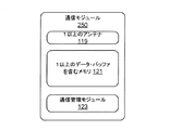
図2Cは、NEDシステムによりデータを受信するために、あるいは別のコンピュータ・システムによりNEDシステムへデータを送信するために使用することができる通信モジュールの一実施形態のブロック図である。有線であるか又は無線である通信媒体に応じて、通信モジュール250は、有線通信又は無線通信を処理するよう具現化され得、場合によっては、含まれるアンテナ及びインタフェース回路の両方次第である。通信モジュール250は、制御回路136内に具現化されるコンピュータ・システム又は付属処理モジュール4内に具現化されるコンピュータ・システム等の、NEDシステムのコンピュータ・システムに通信可能に接続し、そのようなコンピュータ・システムに/からデータを伝送するための機能を提供する。例えば、通信モジュール137は、通信モジュール250の実施形態の機能を具現化することができる。別のNEDシステム8又はネットワーク・アクセス可能なコンピュータ・システム12等のコンピュータ・システムが、図2Cの実施形態等の通信モジュールを含んでもよい。そのような機能のいくつかの例は、1以上の規格又はプロトコル、及び誤り訂正技術に従って伝送のためにデータを符号化するとともに受信データを復号化することや、データを信号に変調し信号からデータを復調すること等の通信技術と、チャネルについてネゴシエートすることや衝突を解決すること等の通信管理アクティビティと、を含む。
FIG. 2C is a block diagram of one embodiment of a communication module that can be used to receive data by the NED system or to send data to the NED system by another computer system. Depending on the wired or wireless communication medium, the
図示した通信モジュールの実施形態は、通信管理モジュール123と、1以上のアンテナ119と、入力データ及び出力データのための1以上のデータ・バッファを含むメモリ121と、を含む。通信管理モジュール123は、画像データの受信及び送信を識別するために、NEDシステム8の1以上のプロセッサと通信する。無損失伝送基準は、通信モジュール250のためにメモリ121に記憶されてもよいし、通信可能に接続されたプロセッサからダウンロードされてもよい。通信管理モジュール123は、1以上のエンコーダと1以上のデコーダとを備え、画像データが無損失伝送のために処理されているか、あるいは損失許容伝送のために処理されているかに基づいて、エンコーダ及びデコーダに命令を提供する。例えば、命令は、順方向誤り訂正(FEC)コード等の誤り訂正技術のための所定のヘッダ・ビットを設定するかどうかと、冗長データを含めるか否かと、を示すことができる。ビット密度は、注目点からの画像データの距離に基づいて変わり得るので、通信管理モジュール123は、変調器及び復調器に命令を提供する。例えば、以下においてユーザ焦点領域画像データと呼ばれるユーザ焦点領域内に表示するための画像データについて、ビット誤り率が無損失伝送基準を満たす1以上の通信チャネルの雑音特性に基づいて推定されるビット誤り率を提供するために選択されたビット・ツー・シンボル密度(bit-to-symbol density)とともに、コンステレーション符号化スキームが割り当てられ得る。
The illustrated communication module embodiment includes a
様々なチャネル状態が、ビット誤り率に影響を及ぼし得る。ビット誤り率は、管理部123によりテスト・パターンを用いて測定され得る、あるいは、検出された雑音レベルに基づいて推定され得る。1以上の雑音低減技術、誤り訂正技術、及び変調技術が、通信管理部123により選択及び適用されてもよいし、1以上の雑音低減技術、誤り訂正技術、及び変調技術が、NEDシステム8の1以上のプロセッサ(例えば、付属処理モジュールの902等の処理ユニット)により選択され、この選択が、通信管理部123に送信され、無損失伝送基準内のビット誤り率をもたらすために、通信管理部123により適用されてもよい。様々な無損失伝送基準が、様々な通信媒体に適用され得る。有線接続は、通信媒体の1つのタイプである。無線接続は、通信媒体の1つのタイプである。例えば、ツイスト・ペア等の異なるケーブル・タイプ又はHDMI(登録商標)といった異なるタイプの有線接続が存在し、IEEE802.11ファミリにおける無線プロトコルのような、無線接続のために適用され得る異なる無線プロトコルが存在する。
Various channel conditions can affect the bit error rate. The bit error rate can be measured by the
本技術は、自然な人間の視野の分解能限界を利用して、伝送されるデータの量を低減させ、人間の眼により知覚される可能性が低い画像データの無損失伝送を確実にする通信技術を回避して時間を節約する。人間の眼は、人間の網膜上で受けられている、所定の波長帯域の光の反射により、「見る」。窩は、網膜の中央にある。窩に到達する光を反射するオブジェクトが、最高のシャープネスで、あるいは人間の視野のための詳細の明瞭さをもって見られる。このタイプの明瞭な視覚(clear vision)は、中心視覚(foveal vision)と呼ばれる。両眼を用いる通常の場合では、人間の眼の注視点若しくは注目点又は注目オブジェクトは、光が反射されて各眼の窩の中央に戻るものである。注目オブジェクトの一例は、本のページ上の単語である。読者がページを見るとき、一般に、注目単語の周囲の複数の単語も明瞭に見える。複数の単語は、注視点を含むユーザ焦点領域内に存在し、ユーザ焦点領域において、オブジェクトは、シャープ又は明瞭に見える。これは、時折単一視覚(single vision)によるものと呼ばれる。 This technology uses the resolution limit of the natural human visual field to reduce the amount of transmitted data and to ensure lossless transmission of image data that is less likely to be perceived by the human eye Avoid time and save time. The human eye “sees” by reflection of light of a predetermined wavelength band received on the human retina. The fovea is in the middle of the retina. Objects that reflect light reaching the fossa are seen with the highest sharpness or with the clarity of detail for the human field of view. This type of clear vision is called foveal vision. In a normal case using both eyes, the gaze point or attention point or attention object of the human eye is such that light is reflected back to the center of the fovea of each eye. An example of the object of attention is a word on a book page. When a reader views a page, the words around the word of interest are generally clearly visible. The plurality of words are present in the user focus area including the gazing point, and the object looks sharp or clear in the user focus area. This is sometimes referred to as single vision.
パーヌム融合(Panum’s fusional)として知られているボリューム(volume)は、人間の眼が単一視覚でオブジェクトを見るボリュームである。人間は、両眼視覚又は立体視覚を有する。各眼は、異なる視点から画像を生成する。パーヌム融合領域のこの小さなボリュームにおいてのみ、人間は、単一視覚でオブジェクトを見る。これは、一般に、オブジェクトに焦点が当てられていると言えるときを意味するものである。この領域外では、オブジェクトは、ぼやけて見えることがある、あるいは二重像として見えることさえある。パーヌム融合領域の中央内にあるのが、ユーザの眼の注目点又は注視点を含むホロプタ(Horopter)である。ユーザが空間内のある点に焦点を当てているとき、空間内のその点は、曲線上に位置する。空間内のこの曲線上のオブジェクトは、窩において眼の網膜に位置する。この曲線は、時折、水平ホロプタ(horizontal horopter)と呼ばれる。注視点の上にある眼から曲線上の注視点の下にある眼に向かって遠ざかるように傾く曲線を介した線である垂直ホロプタ(vertical horopter)も存在する。以下で使用される用語ホロプタは、その垂直成分及び水平成分の両方を指す。 Volume, known as Panum's fusional, is the volume by which the human eye sees an object with a single vision. Humans have binocular vision or stereoscopic vision. Each eye generates an image from a different viewpoint. Only in this small volume of the Panum fusion region, humans see objects with a single vision. This generally means when it can be said that the object is focused. Outside this region, the object may appear blurry or even as a double image. In the center of the Panum fusion region is a horopter that includes the attention point or gaze point of the user's eye. When the user focuses on a point in space, that point in space is located on the curve. An object on this curve in space is located in the retina of the eye in the fovea. This curve is sometimes referred to as a horizontal horopter. There is also a vertical horopter, which is a line through a curve that tilts away from the eye above the gazing point toward the eye below the gazing point on the curve. The term horopta used below refers to both its vertical and horizontal components.
眼球は、しばしば、Gullstrandモデル等、球形状又は半球形状としてモデル化されるので、網膜上の領域のサイズは、しばしば、度若しくはラジアン単位、又は角度測定値で表される。以下において窩と呼ばれる中心窩は、網膜の中心にあり、2度より小さく、例えば、1.2度である。しかしながら、窩は、人間が、他の生物よりも広範な範囲の色を知覚することを可能にし、桿体細胞が提供するよりも、奥行きを含む詳細及び詳細な変化の正確な知覚を可能にする最高密度の錯体細胞を有する。桿体細胞は、網膜上の窩外に存在し、網膜上の錯体細胞の数を大幅に上回る。桿体細胞は、網膜のより広い視野から光を取り込むが、可視光に対する感度は、錯体細胞よりも著しく低い。しかしながら、桿体細胞は動きに対して敏感である。人が、「自分の眼の隅から」何かを見るとき、それは、桿体細胞の感度によるためである。まとめると、錯体細胞は、桿体細胞よりも高い分解能の画像を脳に提供する。網膜の中央にある窩から、錯体細胞の量は低減し、桿体細胞の数は増加する。その結果、人間は、各眼の窩の中心から角距離離れる詳細を知覚する。例えば、窩に近づくと、眼の角度分解能(angular resolution)は、上述したように1分(arcmin)程度である。中心窩から約8度ずれると、眼の自然な角度分解能は、2分を下回る半分だけ低下する。中心窩から約15度ずれると、眼の分解能は、さらに半分だけ、例えば、窩の分解能の4分の1に低下する。 Since the eyeball is often modeled as a spherical or hemispherical shape, such as the Gullstrand model, the size of the region on the retina is often expressed in degrees or radians, or angular measurements. The fovea, referred to below as the fovea, is in the center of the retina and is smaller than 2 degrees, for example 1.2 degrees. However, the fossa allows humans to perceive a wider range of colors than other organisms, and allows more accurate perception of details and details, including depth, than the rods provide. Have the highest density of complex cells. Rod cells are located outside the fossa on the retina, greatly exceeding the number of complex cells on the retina. Rod cells capture light from a wider field of view of the retina, but are much less sensitive to visible light than complex cells. However, rod cells are sensitive to movement. When a person sees something "from the corner of his eye", it is because of the sensitivity of rod cells. In summary, complex cells provide the brain with a higher resolution image than rod cells. From the fovea in the middle of the retina, the amount of complex cells decreases and the number of rod cells increases. As a result, humans perceive details that are angularly separated from the center of the fossa of each eye. For example, when approaching a fovea, the angular resolution of the eye is about 1 minute (arcmin) as described above. A shift of about 8 degrees from the fovea reduces the natural angular resolution of the eye by half, less than 2 minutes. Deviating about 15 degrees from the fovea reduces the eye resolution by an additional half, for example, a quarter of the fovea resolution.
窩に到達する光の人間の眼の分解能は、およそ1分である。例えば、窩の1分の分解能により、ユーザは、ページ上のテキストを読むことが可能となる。60×60度のディスプレイ視野にわたる1分の分解能を実現するために使用される帯域幅の意味を与えるために、次の例が提示される。デュアル1080pビデオ・ストリームは、毎秒5.6ギガビット(5.6Gbps)の通信帯域幅を用いて、毎秒60フレーム(60fps)及びピクセル当たり24ビット(24bpp)で送信される。これは、USB3.0の能力を超えるものであり得、非常に新しい高速通信標準である。1分の分解能での60×60度のディスプレイ視野をカバーするために、34Gbpsという付随するデータ転送速度とともに、驚くべき3600×3600ピクセル解像度が使用される。単一の銅ケーブル・ペアを介して5Gbpsのデータを超えるデータを送信する挑戦は意義がある。 The resolution of the human eye for light reaching the fossa is approximately 1 minute. For example, the 1 minute resolution of the fossa allows the user to read text on the page. The following example is presented to give the meaning of the bandwidth used to achieve 1 minute resolution over a 60 × 60 degree display field of view. The dual 1080p video stream is transmitted at 60 frames per second (60 fps) and 24 bits per pixel (24 bpp) using a communication bandwidth of 5.6 gigabits per second (5.6 Gbps). This can exceed the capabilities of USB 3.0 and is a very new high speed communication standard. In order to cover a 60 × 60 degree display field of view with 1 minute resolution, a surprising 3600 × 3600 pixel resolution is used with an accompanying data transfer rate of 34 Gbps. The challenge of transmitting data in excess of 5 Gbps over a single copper cable pair is significant.
以下のフローチャートは、画像データが表示されることになるディスプレイ視野内の注目点からの距離に基づいて、受信画像データをどのように送信及び処理するかを判定することにより、ディスプレイ更新時間を低減させる方法の実施形態を提供する。図8A及び図8Bで説明する実施形態において、画像データが表示されることになる、注目点周りに集中した領域の観点で、距離を決定することができる。他の手法により、より段階的な形又は継続的な形で伝送品質基準を低減することが可能となる。 The following flowchart reduces display update time by determining how to send and process received image data based on the distance from the point of interest in the display field where the image data will be displayed. An embodiment of a method is provided. In the embodiment described with reference to FIGS. 8A and 8B, the distance can be determined in terms of a region concentrated around the point of interest where image data is to be displayed. Other approaches can reduce transmission quality standards in a more gradual or continuous manner.
図3Aは、送信側コンピュータ・システムの観点からの、NEDデバイスのディスプレイ更新時間を低減させる方法の一実施形態のフローチャートである。NEDデバイスに通信可能に接続された送信側コンピュータ・システムの一例は、付属処理モジュール4内に具現化されたコンピュータ・システムである。別の例において、送信側コンピュータ・システムは、図示したネットワーク・アクセス可能なコンピュータ・システム12(例えば、ゲーム・コンソール又はクラウドベースのゲーム・サービスのコンピュータ・システム)等、NEDデバイス・システム8からリモートにあってもよい。ステップ252において、NEDに通信可能に接続されたコンピュータ・システムは、注目点からディスプレイ視野内に表示するための画像データまでの、ニアアイ・ディスプレイ視野における距離ベクトルを識別する。
FIG. 3A is a flowchart of one embodiment of a method for reducing display update time of a NED device from the perspective of a sending computer system. An example of a sending computer system communicatively connected to a NED device is a computer system embodied in an attached processing module 4. In another example, the sending computer system is remote from the
距離は、画像データの再分割部分(subdivision)の各々について測定することができる。例えば、ピクチャ・エレメント、ディスプレイ・ユニット112のピクセル等の特定のディスプレイ領域により投影される画像データ・セグメントの中心からの距離を測定することができる。別の例において、距離は、例えば、バスケットボール・コート・シーンの3Dマッピングの座標における表示されたバスケットボールの中心等、画像データにより表されるオブジェクトの中心に対するものであってもよい。ステップ254において、注目点からの距離に基づいて、送信側コンピュータ・システムは、表示されることになる画像データの少なくとも一部が、低知覚基準を満たす損失許容データとして適しているかどうかを判定する。ステップ256において、注目点からの距離と、低知覚基準と、に基づいて、送信側コンピュータ・システムは、表示されることになる画像データの少なくとも一部が、低知覚基準を満たさない無損失優先データとして適しているかどうかを判定する。いくつかの例において、距離ベクトルを使用して、各眼について、交点まで戻るディスプレイ視野内の画像データの位置を、近似される網膜位置(例えば、143l及び143r)に関連付ける。交点から近似される中心窩までの角距離ベクトルが、低知覚基準へのより良い関連付けのために決定され得る。
The distance can be measured for each subdivision of the image data. For example, the distance from the center of the image data segment projected by a particular display area, such as a picture element, a pixel of
低知覚基準は、予め定められており、色、構造、及び輝度を決定するための確立された人間の視覚基準(human vision criteria)に基づく。例えば、そのような人間の視覚基準は、人間の網膜上の錯体細胞及び桿体細胞分布のモデルに基づき得る。低知覚基準の一例は、ディスプレイ視野内に投影される画像データからの光が、網膜上で窩から所定の角距離にあることである。 Low perception criteria are predetermined and are based on established human vision criteria for determining color, structure, and brightness. For example, such human visual criteria may be based on a model of complex cell and rod cell distribution on the human retina. One example of a low perceptual criterion is that the light from the image data projected into the display field is at a predetermined angular distance from the fovea on the retina.
注目点からの距離部分は、低知覚基準が満たされるかどうかを判定する際に、大きく重み付けされ得る。画像データは、ディスプレイ視野のエッジの近くにあり得るので、方向もまた、大きな重み付けを受け入れ得る。一般に、画像データが注目点に近いほど、その画像データは、無損失優先画像データとして適している可能性が高く、画像データが注目点から遠くなるほど、画像データは、損失許容画像データとして適している可能性が高い。一般に、以下でさらに説明するように、注目点を取り囲む画像焦点領域内のより多くのデータが、ユーザ焦点領域外に表示するための画像データよりも、無損失優先データとして適している。しかしながら、場合によっては、ユーザ焦点領域内に含まれる、注目点に十分近い画像データであっても、伝送からカットされる所定の低位ビットを有する場合がある。というのは、ユーザ焦点領域内であっても、低位ビットは低知覚基準を満たさないからである。データが周囲の色データに非常に近く、注目オブジェクトが、眼及びおそらくはニアアイ・ディスプレイの色解像度を超えるように、ディスプレイ視野内で十分遠く離れているので、色のためのワード・サイズの最下位ビットの低い数、例えば、2ビットは、損失伝送を用いて送信されることが許容され得る。 The distance portion from the point of interest can be heavily weighted in determining whether the low perceptual criterion is met. Since the image data can be near the edge of the display field of view, the direction can also accept a large weighting. In general, the closer the image data is to the attention point, the higher the possibility that the image data is suitable as lossless priority image data. The farther the image data is from the attention point, the more suitable the image data is as loss-tolerant image data. There is a high possibility. In general, as will be further described below, more data in the image focus area surrounding the point of interest is more suitable as lossless priority data than image data for display outside the user focus area. However, in some cases, even image data that is sufficiently close to the point of interest included in the user focal region may have a predetermined low-order bit that is cut from transmission. This is because even in the user focus area, the low order bits do not satisfy the low perceptual criterion. Since the data is very close to the surrounding color data and the object of interest is far enough in the display field of view to exceed the eye and possibly the color resolution of the near-eye display, the lowest word size for the color A low number of bits, for example 2 bits, may be allowed to be transmitted using lossy transmission.
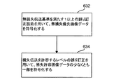
ステップ258において、損失許容データとして適している画像データの少なくとも一部に応じて、コンピュータ・システムは、損失伝送を許容する1以上の通信技術を用いて、損失許容データを送信し、ステップ260において、無損失伝送基準を満たす1以上の通信技術を用いて、損失許容画像データとして適していない画像データである無損失優先画像データを送信する。
In
図3Bは、NEDデバイス・システムの受信側コンピュータ・システムの観点からの、NEDデバイスのディスプレイ更新時間を低減させる方法の一実施形態のフローチャートである。上記で示したように、NEDデバイス・システムの受信側コンピュータ・システムの例は、処理ユニット210と、メモリ244と、通信モジュール137と、を備える制御回路136のハードウェア・コンポーネント及びソフトウェア・コンポーネント、又は付属処理モジュール4内に具現化されるコンピュータ・システムであり得る。
FIG. 3B is a flowchart of one embodiment of a method for reducing display update time of a NED device from the perspective of a receiving computer system of the NED device system. As indicated above, an example of a receiving computer system of a NED device system includes a hardware component and a software component of a
ステップ262において、受信側コンピュータ・システムは、通信可能に接続されたコンピュータ・システムから、画像データを受信し、ステップ264において、無損失伝送基準を満たす1以上の通信技術を用いて送信された、受信されている画像データ内の無損失優先画像データを識別する。ステップ266において、受信側コンピュータ・システムは、無損失伝送基準を満たすよう使用された1以上の通信技術に基づいて、無損失優先画像データを取り出す。
In
ステップ268において、受信側コンピュータ・システムは、受信されている画像データ内の損失許容データを識別し、ステップ270において、損失伝送を許容するよう使用された1以上の通信技術に基づいて、損失許容画像データを取り出す。ステップ272において、NEDデバイスは、NEDデバイスのディスプレイ視野内に、無損失優先画像データ及び損失許容画像データを表示する。
In
上述したように、眼追跡データは、窩の位置を近似するために使用することができる注視点を識別し得る。ユーザ焦点領域は、近似された光が、近似された窩の位置又は近似された窩の中心のある角距離内に含まれる、空間内の領域として識別され得る。例えば、上述した8度の近似を用いると、窩の中心の8度内の領域における画像データは、ユーザ焦点領域内に含まれる。セカンダリ領域(secondary region)もまた識別され得る。「セカンダリ」は、そのような領域がユーザ焦点領域内にはないことを示すために使用される。ユーザ焦点領域の画像データは、最重要なものである、あるいは、ユーザが自然に見ることができない、セカンダリ領域の画像データよりも優先度が高い。 As described above, the eye tracking data may identify a point of gaze that can be used to approximate the position of the fovea. A user focal region may be identified as a region in space where the approximated light is contained within an approximate pit location or an angular distance with the approximate pit center. For example, using the above-described approximation of 8 degrees, the image data in the area within 8 degrees of the center of the fovea is included in the user focal area. A secondary region can also be identified. “Secondary” is used to indicate that such a region is not within the user focus region. The image data in the user focus area is the most important or has higher priority than the image data in the secondary area, which the user cannot naturally see.
指定された領域内の注目点又は位置からの距離に基づいて画像データの解像度を変化させることに加えて、その距離又は関連領域に基づいて、異なるディスプレイ更新速度が適用され得る。例えば、セカンダリ領域内のデータは、毎秒30フレームで更新され得るのに対し、ユーザ焦点領域内のデータは、毎秒60フレームで更新される。 In addition to changing the resolution of the image data based on the distance from the point of interest or position within the specified area, different display update rates may be applied based on the distance or related area. For example, data in the secondary area can be updated at 30 frames per second, whereas data in the user focus area is updated at 60 frames per second.
さらに、サービス品質(QoS)インジケータが、画像の再分割部分ごとに、例えば、記憶される画像データの一部としてピクセル又はボクセルで、記憶され得る。したがって、QoSインジケータを使用して、画像データにおける優先度、量、及び再分割部分の許容データ損失のタイプを識別することができる。例えば、輝度よりも色に関して許容されないデータ損失が存在し得る。1つのQoSバケット(QoS bucket)に量子化されたピクセルは、眼がどのように機能するかに基づいて、画像の1つの領域に集まる。さらに、異なるQoS数又はインジケータが、ビットが低知覚基準を満たすか否かを判定する際に送信側コンピュータにより使用され得るピクセルに関連付けられた各ビットについて記憶され得る。そのようなアプローチの結果は、低優先度ビットの損失が高いほど、画像データは注目点から遠くなるが、それでも、その画像データのより高い優先度ビットの高画像品質を得る、ということであり得る。異なる伝送処理を示す1以上のQoSインジケータの値は、無損失伝送基準の一部であり得る。 Further, a quality of service (QoS) indicator may be stored for each subdivision portion of the image, eg, in pixels or voxels as part of the stored image data. Thus, the QoS indicator can be used to identify the priority, amount, and type of allowable data loss for the subdivision portion in the image data. For example, there can be unacceptable data loss in terms of color rather than luminance. Pixels quantized into a single QoS bucket gather in a region of the image based on how the eye functions. In addition, a different QoS number or indicator may be stored for each bit associated with a pixel that may be used by the sending computer in determining whether the bit meets a low perceptual criterion. The result of such an approach is that the higher the loss of low priority bits, the farther the image data is from the point of interest, but still get a higher image quality of the higher priority bits of that image data. obtain. One or more QoS indicator values indicating different transmission processes may be part of a lossless transmission criterion.
図4Aは、ディスプレイ・デバイス2を装着しているユーザ周囲の空間の3Dマッピングにおける、仮想オブジェクトの3次元(3D)空間位置の一例を示している。3D空間位置は、オブジェクトがどれくらい空間を占有しているかと、空間を占有した3Dディスプレイ視野内のどこに配置されているかと、を識別する。例示的なコンテキストは、ユーザが敵ヘリコプタ202を撃墜するゲームである。(現実オブジェクト及び仮想オブジェクトのマッピングについては、図5を参照してより詳細に説明する。)
FIG. 4A shows an example of the three-dimensional (3D) spatial position of the virtual object in the 3D mapping of the space around the user wearing the
図4Aのヘリコプタ202が、人間の中心視覚のための角度分解能1分を満たすためにディスプレイにより使用される解像度で示されている。尾部及び尾部ロータを有するヘリコプタ202aは、この例においてはユーザ焦点領域外のデフォルト領域である第3の領域301及びユーザ焦点領域外の第2の領域内の上方左のディスプレイ視野にある。ヘリコプタ202bは、中央からちょうど上の右のディスプレイ視野からディスプレイ視野の中央に向かうわずかに下方の軌道上にあり、ディスプレイ視野の中央において、ヘリコプタ202cは、ユーザに向かって真っすぐに進んでおり、ヘリコプタ202cは、網膜143l及び網膜143r上の窩から伸びる注視線701l及び注視線701rにより示される現在の注目オブジェクトである。これらの仮想ヘリコプタ202は動いており、ユーザは、ヘリコプタを撃墜するために自分の頭部を動かしている可能性がかなり高いので、画像データは、リアルタイムに3次元で更新されている。
The helicopter 202 of FIG. 4A is shown with the resolution used by the display to meet an angular resolution of 1 minute for human central vision. A
人間の視覚の限界に起因して、図示するヘリコプタが全て、ユーザ焦点領域101に含まれないとき、ユーザは、そのようなディスプレイ解像度で、図示するヘリコプタ全てを自然に解像することはないであろう。NEDデバイス・システムは、人間の網膜に沿った知覚分解能の差異を利用することができる。図4Bとともに使用される図4Aは、ユーザ焦点領域外の第2の領域における中央画像解像度レベル又は中間画像解像度レベルを含むより低い画像解像度レベルと、ユーザ焦点領域画像データ外のユーザ焦点領域画像データからより遠い第3の領域301の低画像解像度レベルと、の例を示している。QoSもまた、ここにおいて、画像データの再分割部分のために記憶されたQoS及び各ビットについて記憶されたQoSが、より低い解像度レベルにあってもビットが損失許容可能であり得るチェック又は限界として動作するという点で、結び付けられ得る。
Due to the limitations of human vision, when all of the illustrated helicopters are not included in the
図4Aはまた、ユーザ焦点領域101と、セカンダリ領域201及び301と、の例を示している。図示した例において、それぞれの眼からの注視線701l及び注視線701rが近似される眼追跡データに基づいて、注視点が決定される。注視線は、眼の窩からディスプレイ視野への視線の近似を表す。両方の注視線が交わる場所が注視点であり、注視点は注目点の一例である。ユーザ焦点領域は注視点を含む。左眼140lに関して、注視線701lは、網膜143l上の中心からわずかに左にずれている窩699lからディスプレイ視野に伸び、ヘリコプタ202cに伸びる。右眼140rに関して、注視線701rは、網膜143r上の中心からわずかに右にずれている窩699rからディスプレイ視野に伸び、ヘリコプタ202cに伸びる。異なる実施形態は、モデル化技術を使用して、ディスプレイ視野内のパーヌム融合領域及びホロプタを識別する。現在の例のような他の実施形態は、人間の視覚を研究する分野からの周知の近似を使用することができる。
FIG. 4A also shows an example of the
説明を続ける前に、図面は縮尺通りに描かれていないことに留意されたい。図4Aのこの例において、注視点を含むユーザ焦点領域は、4つの線702la,702lb,702ra、及び702rbにより特定される。この例では、線702laは、網膜上で注視線701lと窩との交点の左に約8度の点からディスプレイ視野に伸びる線を表す。補完的に、線702lbは、網膜上で注視線701lと窩との交点の右に約8度の点からディスプレイ視野に伸びる線を表す。同様に、線702raは、注視線701rと窩との交点の左に約8度の網膜からディスプレイ視野に伸びる。線702rbは、注視線701rと窩との交点の右に約8度の網膜からディスプレイ視野に伸びる。
Before continuing, it should be noted that the drawings are not drawn to scale. In this example of FIG. 4A, the user focal region including the point of gaze is identified by four lines 702la, 702lb, 702ra, and 702rb. In this example, line 702la represents a line extending from the point of about 8 degrees to the display field on the retina to the left of the intersection of the gaze line 701l and the fovea. Complementarily, line 702lb represents a line extending from the point of about 8 degrees to the display field on the retina to the right of the intersection of the gaze line 701l and the fovea. Similarly, line 702ra extends from the retina about 8 degrees to the display field to the left of the intersection of
線702lbと線702rbとの交点は、ユーザ焦点領域のディスプレイ視野における左の境界上の点を形成する。同様に、線702laと線702raとの交点は、ユーザ焦点領域のディスプレイ視野における右の境界上の点を形成する。この例において、球形の形状(geometry)は、ユーザ焦点領域101を特定するために使用され、左の境界点及び右の境界点は、球形の直径を表す。例えば、矩形、円形、3D矩形、正方形、又は立方体といった異なる形状が、設計選択事項として使用されてもよい。
The intersection of line 702lb and line 702rb forms a point on the left boundary in the display field of the user focus area. Similarly, the intersection of line 702la and line 702ra forms a point on the right boundary in the display field of the user focus area. In this example, a spherical geometry is used to identify the user
またこの例において示されるように、第2の領域201も特定される。この領域では、表示のための画像データは、参照の目的のためセカンダリ画像データと呼ばれる。セカンダリ画像データは、ユーザ焦点領域外に表示するためのデータである。この例において、第3の領域301の画像データもまた、セカンダリ画像データと呼ばれる。この例において、第3の領域301は、ユーザ焦点領域外であるデフォルト領域であり、第2の領域は、ディスプレイ視野内にある。
As shown in this example, the
線703laが、網膜上で注視線701lと窩との交点の左に約15度であり、線703lbが、網膜上で注視線701lと窩との交点の右に約15度であることを除いて、第2の領域もユーザ焦点領域と同様に特定される。右眼に関して、線703ra及び線703rbは、注視線701rと窩との交点のそれぞれ左に約15度及び右に約15度の網膜上の交点からディスプレイ視野に伸びる。線703lbと線703rbとの交点は、第2の領域のディスプレイ視野における第2の左の境界上の点を形成し、線703laと線703raとの交点は、第2の領域のディスプレイ視野における第2の右の境界上の点を形成する。これら第2の左の境界及び第2の右の境界を有し、ユーザ焦点領域を含む球形201、したがって、注視点は、第2の領域を表す。
Line 703la is about 15 degrees to the left of the intersection of the gaze line 701l and the fovea on the retina, and line 703lb is about 15 degrees to the right of the intersection of the gaze line 701l and the fovea on the retina Thus, the second area is identified in the same manner as the user focus area. For the right eye, line 703ra and line 703rb extend into the display field from the intersection on the retina about 15 degrees to the left and about 15 degrees to the right of the intersection of the
人間の視覚は、周辺視野を含め約200度まで広がり得るが、前述したディスプレイ視野は、そこまで広がり得ない。例えば、頭部のサイズと、眼鏡産業及びHMD分野からのその頭部の細部の眼のモデルと、に基づいて決定される、例えば、NEDデバイスの窩の近似された位置から、ディスプレイ視野は、3次元の各々において、約60度、例えば、水平方向に60度、垂直方向、及び奥行き方向に広がり得る。ユーザ焦点領域101及び第2の領域201は、約30度のディスプレイ視野を表す。
Human vision can extend up to about 200 degrees, including the peripheral vision, but the display vision described above cannot extend that far. For example, from the approximate position of the fossa of the NED device, determined from the size of the head and the eye model of that head's detail from the spectacle industry and HMD field, the display field is In each of the three dimensions, it can extend approximately 60 degrees, for example 60 degrees horizontally, vertically, and depth. The
上述したように、自然な視覚の分解能は、網膜上の窩から8度から15度の間、半分だけ低下し、15度以降についてさらに半分だけ低下する。この例において、ユーザ焦点領域は、1分の角度分解能を満たすディスプレイ解像度を有し、第2の領域は、約2分の角度分解能を満たす中央解像度を有し、第3の領域は、低解像度を有する。例えば、低解像度は、4分の角度分解能を満たし得る。いくつかの例において、第2の領域を超えるデータは、表示されさえしないこともある、あるいは、ディスプレイ更新速度制約を維持するために表示の最低優先度を有することもある。 As described above, natural visual resolution is reduced by half between 8 and 15 degrees from the fossa on the retina, and by another half after 15 degrees. In this example, the user focus area has a display resolution that satisfies an angular resolution of 1 minute, the second area has a central resolution that satisfies an angular resolution of about 2 minutes, and the third area has a low resolution. Have For example, low resolution can satisfy an angular resolution of 4 minutes. In some examples, data beyond the second region may not even be displayed, or may have a lowest priority of display to maintain display update rate constraints.
図4Bは、ユーザ焦点領域内又はユーザ焦点領域外の位置に基づいて画像解像度を変えるNEDデバイスにより表示されている仮想ヘリコプタの例を含むディスプレイ視野の一例を示している。ヘリコプタ202aは、第3の領域にあるので、この例において、ユーザは、ユーザ焦点領域の自然な眼の角度分解能の4分の1で、ヘリコプタ202aを見るであろう。ヘリコプタ202aの画像データは、この眼の分解能を満たす低画像解像度で提示される。ヘリコプタ202aの尾部ロータは、尾部と同様、領域を有する矩形形状ではなく、線である。ヘリコプタ本体の曲線は、くぼみ(indentation)を失い、チョッパ(chopper)の眼鏡のサイド部分のような境界楕円(bounding ellipse)により表される。上部ロータもまた、矩形ボリュームを有する全ての3つのロータではなく、線である。解像度の損失に加えて、その効果は、人間の眼により気付かれるものではないので、ロータは、この第3の領域の画像データについて、伝送において失われることが許容されるであろう。着陸装置の下の一部(piece)のみが線により表されている。ヘリコプタは、ユーザの眼が画像を取り込むであろう自然な解像度をさらに低減させるように動いている。
FIG. 4B shows an example of a display field of view including an example of a virtual helicopter displayed by a NED device that changes the image resolution based on a position within or outside the user focus area. Since
ヘリコプタ202bは、第2の領域及び第3の領域にまたがって表示されている。画像データのダウンサンプリングを使用して、中央解像度バージョン及び低解像度バージョンを得ることができる。第2の領域内の上部ロータは、より細くなっているが、それでも何らかの矩形領域を有する。ヘリコプタのコックピットの本体の境界の曲線又はくぼみは、流線形であるが、それでも、形状は、ユーザ焦点領域のボリュームを有している。コックピットの窓の境界は、ダウンサンプリングに起因して、ユーザ焦点領域の正確な湾曲を失っている。第3の領域に伸びる上部ロータの一部は、線として見え、上部モータのベースは、垂直方向に薄くなっている。第3の領域内の尾部及び尾部ロータは、第3の領域内のヘリコプタ202aと同様に、線として表示されている。
The
ユーザ焦点領域内のヘリコプタ202cは、図4Aと同一に見える。
The
図4Cは、ジェスチャがNED視野内の注目点を示す、図4Bのヘリコプタの例の別のバージョンを示している。この例において、ヘリコプタ202cに対するポインティング・ジェスチャを実行する、人間の手385の人間の指387が検出される。オブジェクトに対するジェスチャを使用して、注目オブジェクトを識別することもできる。例えば、仮想オブジェクト又は現実オブジェクトは、指又はハンドヘルド・オブジェクトを用いて指し示すことができる、あるいはユーザは、現実オブジェクト又は仮想オブジェクトに対して、保持ジェスチャ又は把持ジェスチャを行うことができる。ユーザ焦点領域101と、セカンダリ領域201及び301と、が、各網膜143の近似された位置上の窩の近似された位置に基づいて識別され得る。例えば、網膜の位置は、NEDディスプレイ・デバイスの頭部のサイズと、人間の眼球のモデルと、に基づいて近似され得る。そのようなモデルの一例は、Gullstrand図式眼モデルである。ジェスチャが向けられるオブジェクト又はポイントの3Dマッピング座標から、ディスプレイ視野内のオブジェクト又はポイントの位置が、各光軸142がそのそれぞれのディスプレイ・ユニットとどこで交わり、次いで、そこを近似された網膜の位置上の1以上の交点に関連付けることができるか等、デバイス上の1以上の基準点に再度関連付けられ得る。他の例において、オブジェクト又は注目点が、その3Dマッピング座標により、再度、近似された網膜の各位置上の1以上の交点に直接関連付けられ得る。
FIG. 4C shows another version of the example helicopter of FIG. 4B where the gesture indicates a point of interest in the NED field of view. In this example,
この例において、近似された網膜の位置上の1以上の交点からの各距離もまた、図4A及び図4Bの例とちょうど同じように使用して、セカンダリ領域を識別することができる。例示の目的上、指387により示されるユーザが指し示している、ディスプレイ視野内の点からの線701l及び線701rとして示されている光線が、近似された網膜143の位置における交点に戻るよう跡をたどられ、注視線として効果的に動作する。
In this example, each distance from one or more intersections on the approximated retina position can also be used just as in the example of FIGS. 4A and 4B to identify secondary regions. For illustrative purposes, the trace indicated by the user indicated by the
他の例において、アプリケーションのタイプに基づいて、注目点及びユーザ焦点領域が、画像データがディスプレイ視野内のどこに表示されるか判定されることに基づいて、識別され得る。すなわち、ユーザは、表示されている新たなデータ又はその動きパターンを変えるデータを見る傾向にあるので、ユーザ焦点領域は、ユーザが焦点をどこに動かすかの予測に基づいて選択される。ユーザ焦点領域を識別するこれらの方法のうち2以上の組合せが使用されてもよい。例えば、アップデート時間基準(update time criteria)内のディスプレイ更新時間を保つために、眼追跡データに基づいてユーザ焦点領域の更新を待つ間に、画像データにおける変化が生じる視野内の予め定められた位置が、ユーザ焦点領域として使用され得る。 In other examples, based on the type of application, the point of interest and user focus area may be identified based on determining where the image data is displayed within the display field of view. That is, because the user tends to see the new data being displayed or data that changes its motion pattern, the user focus area is selected based on a prediction of where the user will move the focus. A combination of two or more of these methods of identifying the user focus area may be used. For example, a predetermined position in the field of view where changes in image data occur while waiting for an update of the user focus area based on eye tracking data to maintain display update time within update time criteria Can be used as the user focus area.
図5は、ニアアイ・ディスプレイ・デバイスにより画像データを表示するための、ソフトウェアの観点からの、システムの一実施形態のブロック図である。図5は、NEDシステム8、1以上のNEDシステムと通信する1以上のリモート・コンピュータ・システム12、又はそれらの組合せ等のシステムにより実装され得る、ソフトウェアの観点からのコンピューティング環境54の一実施形態を示している。さらに、NEDシステムは、データを共有してリソースを処理するために、他のNEDシステムと通信することができ、データのための、環境内の他の3D画像キャプチャ・デバイス20等の他の画像キャプチャ・デバイスと通信することもできる。
FIG. 5 is a block diagram of one embodiment of a system from a software perspective for displaying image data with a near-eye display device. FIG. 5 illustrates one implementation of a computing environment 54 from a software perspective that may be implemented by a system such as
この実施形態において、アプリケーション162が、NEDシステム8の1以上のプロセッサ上で実行されており、オペレーティング・システム190及び画像・オーディオ処理エンジン191と通信していることがある。アプリケーションは、拡張現実体験、仮想現実体験、又は拡張視覚体験のためのものであり得る。図示した実施形態において、リモート・コンピュータ・システム12がまた、体験を高めるために通信する他のNEDシステム8と同様に、アプリケーションのバージョン162Nを実行していることがある。
In this embodiment, application 162 is running on one or more processors of
1以上のアプリケーションのアプリケーション・データ329がまた、1以上のネットワーク・アクセス可能な位置に記憶され得る。アプリケーション・データ329のいくつかの例は、ルール・データストア、オブジェクトの画像データ及びアプリケーションの画像(imagery)、ジェスチャ認識エンジン193により登録され得る、アプリケーションに関連付けられた1以上のジェスチャの参照データ、1以上のジェスチャのための実行基準、画像・オーディオ処理エンジンのオプションの物理学エンジン(図示せず)により登録され得る、アプリケーションに関連付けられた仮想オブジェクトのための物理学モデル、及び、オブジェクト物理特性データ・セット320に関連付けられ得る、仮想オブジェクトの色、形状、顔の特徴、装具(clothing)等のオブジェクト特性であり得る。 Application data 329 for one or more applications may also be stored in one or more network accessible locations. Some examples of application data 329 include a rule data store, object image data and application imagery, one or more gesture reference data associated with the application that may be registered by the gesture recognition engine 193, Execution criteria for one or more gestures, physics models for virtual objects associated with the application, and object physics properties that can be registered by an optional physics engine (not shown) of the image and audio processing engine There may be object characteristics such as color, shape, facial features, clothing, etc. of the virtual object that may be associated with the data set 320.
図5の実施形態に示されるように、コンピューティング環境54のソフトウェア・コンポーネントは、オペレーティング・システム190と通信する画像・オーディオ処理エンジン191を含む。画像・オーディオ処理エンジン191は、NEDシステム8等のヘッド・マウント・ディスプレイ(HMD)デバイス・システムのために実行されるアプリケーションをサポートするために、画像データ(例えば、ビデオ等の動きデータ又は静止)及びオーディオ・データを処理する。画像・オーディオ処理エンジン191の実施形態は、様々な機能を含み得る。図示した実施形態は、他の機能に含まれ、他の機能により示され、他の機能を追加することができる実行可能ソフトウェア・エレメントの選択を示している。画像・オーディオ処理エンジン191の図示した実施形態は、オブジェクト認識エンジン192、ジェスチャ認識エンジン193、ディスプレイ・データ・エンジン195、3Dオーディオ・エンジン304、音認識エンジン194、ユーザ焦点領域エンジン196、及びシーン・マッピング・エンジン306を含む。
As shown in the embodiment of FIG. 5, the software components of computing environment 54 include an image and audio processing engine 191 that communicates with an operating system 190. The image and audio processing engine 191 provides image data (eg motion data such as video or still) to support applications executed for head mounted display (HMD) device systems such as the
コンピューティング環境54はまた、データを1以上の画像・オーディオ・データ・バッファ199に記憶する。このバッファは、様々なソースからキャプチャされ得る、あるいは様々なソースから受信され得る画像データ及びオーディオ・データのためのメモリを提供する。例えば、このバッファは、通信可能に接続されたコンピュータ・システム12から通信媒体を介してNEDデバイス2又は付属処理モジュール4のいずれかにより受信された、表示のための画像データを記憶することができる。このバッファは、例えば、全メモリ244の一部として、NED上に存在してもよいし、付属処理モジュール4上に存在してもよい。付属処理モジュール4上の1以上のバッファは、NEDデバイス2に送信されることになる、表示のための画像データを保持することができる。少なくとも一時的にバッファに記憶することができるいくつかの他のタイプの画像データは、NEDシステム8の外側対面キャプチャ・デバイス113からキャプチャされた画像データ、利用可能である場合、他のキャプチャ・デバイス(例えば、3D画像キャプチャ・デバイス20及び環境内の他のNEDシステム8)によりキャプチャされた画像データ、使用される場合、眼追跡システムの眼追跡カメラからの画像データである。このバッファはまた、画像生成ユニット120により表示されることになる仮想オブジェクトの画像データを保持するためのバッファと、マイクロフォン110を介してユーザからキャプチャされた音等の入力及び出力両方のオーディオ・データ、並びにイヤフォン130等のオーディオ出力デバイスを介してユーザに出力されることになる、3Dオーディオ・エンジン304からのアプリケーションのためのサウンド・エフェクトのためのバッファと、を提供する。
The computing environment 54 also stores data in one or more image audio data buffers 199. This buffer provides memory for image and audio data that can be captured from various sources or received from various sources. For example, the buffer may store image data for display received by the
図5の個々のエンジン及びデータ・ストアは、アプリケーション162が利用できるデータ及びタスクのサポート・プラットフォームとして設けられている。画像・オーディオ処理エンジン191の様々なエンジンは、データ・アップデートの通知を処理して受信するためにデータを識別するリクエストを送信することにより、1以上の機能を実装する。オペレーティング・システム190は、様々なエンジンとアプリケーションとの間の通信を円滑にする。オペレーティング・システム190は、ジェスチャ認識エンジン193がどのジェスチャを識別したかと、音認識エンジン194がどの単語又は音を識別したかと、上述したシーン・マッピング・エンジン306からのオブジェクトの位置と、をアプリケーションに利用可能にする。 The individual engines and data stores of FIG. 5 are provided as data and task support platforms that can be utilized by the application 162. The various engines of the image and audio processing engine 191 implement one or more functions by sending a request to identify data to process and receive data update notifications. Operating system 190 facilitates communication between various engines and applications. The operating system 190 tells the application which gesture recognition engine 193 has identified, which word or sound the sound recognition engine 194 has identified, and the position of the object from the scene mapping engine 306 described above. Make it available.
シーン・マッピング・エンジン306についてまず説明する。NEDデバイスの各ディスプレイのディスプレイ視野の3Dマッピングは、キャプチャされた画像データ及び奥行きデータに基づいて、シーン・マッピング・エンジン306により決定され得る。3Dマッピングは、ディスプレイ視野内の現実オブジェクト又は仮想オブジェクトの3D位置を含む。いくつかの実施形態において、特にディスプレイに関して、3Dマッピングは、3D位置の例としての、オブジェクトの3D空間位置又は位置ボリューム(position volume)を含み得る。3D空間は、オブジェクトにより占有される空間のボリュームである。3D空間位置は、そのボリュームの境界の位置座標、又はディスプレイ視野を含む座標系における3D空間を表す。望まれる正確さに応じて、3D空間は、オブジェクトの3D形状をマッチングすることができる、あるいはあまり正確でないバウンディング形状(bounding shape)であり得る。いくつかの例において、3D空間位置は、オブジェクトの向き等の追加の情報を含む。他の例において、3D位置は、例えば、バウンディング円形、矩形、三角形等の2Dバウンディング形状と、オブジェクトの、ディスプレイ視野における奥行き位置と、を含む。 First, the scene mapping engine 306 will be described. A 3D mapping of the display field of view of each display of the NED device may be determined by the scene mapping engine 306 based on the captured image data and depth data. 3D mapping includes the 3D position of a real or virtual object in the display field of view. In some embodiments, particularly with respect to the display, the 3D mapping may include a 3D spatial position or position volume of the object as an example of a 3D position. A 3D space is a volume of space occupied by an object. The 3D space position represents the position coordinates of the boundary of the volume or the 3D space in the coordinate system including the display field of view. Depending on the accuracy desired, the 3D space can match the 3D shape of the object or can be a less accurate bounding shape. In some examples, the 3D spatial position includes additional information such as the orientation of the object. In other examples, the 3D position includes, for example, a 2D bounding shape such as a bounding circle, rectangle, triangle, and the depth position of the object in the display field of view.
外側対面キャプチャ・デバイス113からのキャプチャされた画像データ及び奥行きデータを表す奥行きマップを、ニアアイ・ディスプレイのディスプレイ視野の3Dマッピングとして使用することができる。奥行きマップは、ユーザ視点を大まかに表す、ディスプレイ視野のビュー依存の座標系(view dependent coordinate system)を有する。キャプチャされたデータは、現実オブジェクトの動きを追跡するために、キャプチャ時間に基づいて、時間追跡され得る。仮想オブジェクトの位置が、奥行きマップにおいて位置合わせされ得る。
A depth map representing captured image data and depth data from the outer face-to-
ユーザの環境内のユーザの周りにあるものをマッピングすることは、センサ・データにより支援され得る。例えば、3軸加速度計及び3軸磁力計といった慣性検出ユニット132からのデータが、ユーザの頭部の位置変化を決定し、そのような頭部の位置変化と、外側対面キャプチャ・デバイス113からの画像データ及び奥行きデータにおける変化と、の相関は、互いに対するオブジェクトの位置であって、ユーザが見ている環境又は位置のサブセットにおけるオブジェクトの位置を識別し得る。
Mapping what is around the user in the user's environment can be aided by sensor data. For example, data from inertial detection unit 132, such as a 3-axis accelerometer and a 3-axis magnetometer, determines a change in the position of the user's head, and the change in position of the head from the outer facing
シーン・マッピング・エンジン306はまた、3Dマッピングのためにビュー非依存の座標系を使用することができ、シーン・マッピング・エンジン306のコピーは、他のシステム(例えば、12、20、及び8)において実行されている他のシーン・マッピング・エンジン306と通信することができるので、マッピング処理は、更新されたマップを他のシステムと共有する1つのコンピュータ・システムにより、集中的に共有又は制御することができる。複数の視点から得られる奥行き画像内の重なり合う対象物(overlapping subject matter)が、ビュー非依存の座標系及び時間と、ボリューメトリック(volumetric)又は位置若しくは環境(例えば、部屋、店舗空間、又はジオフェンス領域(geofenced area)のx、y、z表現)の3Dマッピングを作成するために結合された画像コンテンツと、に基づいて、相互に関連付けられ得る。したがって、光、影、及びオブジェクト位置における変化が追跡され得る。 The scene mapping engine 306 can also use a view-independent coordinate system for 3D mapping, and copies of the scene mapping engine 306 can be used for other systems (eg, 12, 20, and 8). The mapping process is centrally shared or controlled by one computer system that shares the updated map with other systems because it can communicate with other scene mapping engines 306 running at be able to. Overlapping subject matter in depth images obtained from multiple viewpoints is a view-independent coordinate system and time, and volumetric or location or environment (eg, room, store space, or geofence) Based on the image content combined to create a 3D mapping of the x, y, z representation of the area (geofenced area). Thus, changes in light, shadow, and object position can be tracked.
ビュー非依存のマップは、位置インデックス付き画像及び3Dマップ(location indexed images and 3D maps)324等のネットワーク・アクセス可能な位置に記憶することができる。位置インデックス付き画像及び3Dマップ324を検索するための位置データのいくつかの例は、ニアアイ・ディスプレイ(NED)上の位置検出ユニット144のGPSトランシーバからのGPSデータ、又はNEDシステム8が接続しているWiFi(登録商標)ホットスポット又はセルラ・ステーションのIPアドレスである。(画像データへのアクセスを伴う、装置8等のHMDとコンピュータ・システム12との間の協調的シーン・マッピングに関するさらなる情報については、Avi Bar-Zeevらの2010年10月27日に出願された「Low-Latency Fusing of Virtual and Real Content」と題する米国特許出願番号12/912937号を参照されたい。)
View independent maps can be stored in network accessible locations such as location indexed images and 3D maps 324. Some examples of position data for retrieving position indexed images and 3D maps 324 include GPS data from the GPS transceiver of the
シーン・マッピング・エンジン306は、画像・オーディオ処理エンジン191のオブジェクト認識エンジン192、及び画像データを表示させる1以上の実行アプリケーション162との通信に基づいて、ディスプレイ視野内又はユーザ周囲のボリューメトリック空間(volumetric space)内の現実オブジェクト及び仮想オブジェクトの位置、向き、及び動きを追跡する。 The scene mapping engine 306 is based on communication with the object recognition engine 192 of the image and audio processing engine 191 and one or more execution applications 162 that display the image data, in a volumetric space (in the display field of view or around the user). Track the position, orientation, and movement of real and virtual objects in the volumetric space.
画像・オーディオ処理エンジン191のオブジェクト認識エンジン192は、キャプチャされた画像データと、利用可能である場合にはキャプチャされた奥行きデータと、に基づいて、あるいは立体視からの決定された奥行き位置に基づいて、ディスプレイ視野内の現実オブジェクト、その向き、及びその位置を検出及び識別する。オブジェクト認識エンジン192は、オブジェクト境界をマーキングし、オブジェクト境界を構造データと比較することにより、現実オブジェクトを互いと区別する。オブジェクト境界をマーキングする1つの例は、検出又は導出された奥行きデータ及び画像データ内のエッジを検出して、エッジを接続することである。ポリゴン・メッシュを使用して、オブジェクトの境界を表現してもよい。次いで、確率基準(probability criteria)内のオブジェクトのタイプを識別するために、オブジェクト境界データが、記憶された構造データ200と比較される。オブジェクトのタイプを識別することに加えて、記憶された構造データ200との比較に基づいて、識別されたオブジェクトの向きが検出され得る。
The object recognition engine 192 of the image / audio processing engine 191 is based on captured image data and captured depth data, if available, or based on a determined depth position from stereoscopic view. Detecting and identifying a real object, its orientation, and its position in the display field of view. The object recognition engine 192 distinguishes real objects from each other by marking object boundaries and comparing the object boundaries with structural data. One example of marking object boundaries is detecting edges in detected or derived depth data and image data and connecting the edges. Polygon meshes may be used to represent object boundaries. The object boundary data is then compared with the stored
1以上の通信ネットワーク50を介してアクセス可能な構造データ200は、比較のための構造パターン及びパターン認識のための基準としての画像データ等の構造情報を記憶することができる。無生物オブジェクト(inanimate object)に加えて、他の画像処理アプリケーションと同様に、人間はオブジェクトの1タイプであり得るので、構造データの一例は、身体パーツを認識するのを助けるために参照され得る、記憶された人間の骨格モデルである。画像データがまた、顔認識のために使用されてもよい。オブジェクト認識エンジン192はまた、ユーザのユーザ・プロファイル・データ197、パーミッションが設定されネットワーク・アクセス可能な他のユーザのプロファイル・データ322、位置インデックス付き画像及び3Dマップ324、並びにインターネット・アクセス可能な画像326等の、他のソースからの記憶された画像データにも基づいて、オブジェクトの画像データに対して、顔認識及びパターン認識を実行することができる。画像データ及び奥行きデータからのモーション・キャプチャ・データもまた、オブジェクトの動き特性を識別し得る。オブジェクト認識エンジン192はまた、サイズ、形状、1以上の材料、及び動き特性等のオブジェクトの検出された特性を、構造データ200に記憶された基準特性に対して、チェックすることができる。基準特性(例えば、構造パターン及び画像データ)はまた、仮想オブジェクトを生成するために、アプリケーションによりアクセスされ得る。
The
現実オブジェクトに関して、3Dサイズ、3D形状、検出された材料のタイプ、1以上の色、及び検出された境界形状等の複数のオブジェクト特性の各々について、データが割り当てられ得る。一実施形態において、基準特性との比較後にオブジェクト認識エンジン192により割り当てられた、検出された特性ごとの重み付き確率に基づいて、オブジェクトと、オブジェクト特性データ・セット320Nに記憶されたその特性と、が識別される。オブジェクトの検出及び追跡に関するさらなる情報は、2009年12月18日に出願された「Motion Detection Using Depth Images」と題する米国特許出願12/641788号と、「Device for Identifying and Tracking Multiple Humans over Time」と題する米国特許出願12/475308号と、において見い出すことができる。
For a real object, data may be assigned for each of a plurality of object characteristics such as 3D size, 3D shape, detected material type, one or more colors, and detected boundary shape. In one embodiment, based on the weighted probability for each detected property assigned by the object recognition engine 192 after comparison with the reference property, the object and its property stored in the object property data set 320N; Is identified. More information on object detection and tracking can be found in US patent application Ser. No. 12/64788, entitled “Motion Detection Using Depth Images,” filed Dec. 18, 2009, and “Device for Identifying and Tracking Multiple Humans over Time”. And can be found in the entitled
シーン・マッピング・エンジン306及びオブジェクト認識エンジン192は、その機能において各エンジンを支援するデータを交換する。例えば、オブジェクト識別と、オブジェクト認識エンジン192により決定された向きと、に基づいて、シーン・マッピング・エンジン306は、より正確に向きを識別するオブジェクトの3D空間位置又は位置ボリュームを更新することができる。例えば、横にある椅子は、右横に立っているときと比べて、そのボリュームの異なる位置座標を有する。位置の履歴と、オブジェクトに関してシーン・マッピング・エンジン306により更新された3D位置から識別された動き経路(motion path)と、は、特にオブジェクトが部分的に隠されているときに、オブジェクトを識別するオブジェクト認識エンジン192を支援し得る。 The scene mapping engine 306 and the object recognition engine 192 exchange data that supports each engine in its function. For example, based on the object identification and orientation determined by the object recognition engine 192, the scene mapping engine 306 can update the 3D spatial position or position volume of the object that more accurately identifies the orientation. . For example, a chair on the side has different position coordinates for its volume compared to standing on the right side. The history of location and the motion path identified from the 3D location updated by the scene mapping engine 306 for the object identifies the object, especially when the object is partially hidden. The object recognition engine 192 may be supported.
一実施形態において、ユーザ焦点領域エンジン196は、表示されるようスケジュールされた画像データの3Dディスプレイ視野内の座標を識別するために、アプリケーション162及びシーン・マッピング・エンジン306と通信する。例えば、アプリケーション162は、20cmの奥行きを有して上方左位置に表示されることになるポップアップ・メニューを識別することができ、シーン・マッピング・エンジン306は、ディスプレイ視野の3Dマッピング座標におけるこの位置を識別する。ポップアップ・メニューは注目オブジェクトである。いくつかの例において、ディスプレイ視野は、立方体又は他のボリューメトリック・ユニットに編成される。注目オブジェクトの一部を含む立方体は、ユーザ焦点領域の一部であると考えられる。 In one embodiment, the user focus area engine 196 communicates with the application 162 and the scene mapping engine 306 to identify coordinates within the 3D display field of view of the image data scheduled to be displayed. For example, the application 162 can identify a pop-up menu that will be displayed in the upper left position with a depth of 20 cm, and the scene mapping engine 306 will display this position in 3D mapping coordinates of the display field of view. Identify The pop-up menu is the object of interest. In some examples, the display field is organized into a cube or other volumetric unit. A cube including a part of the target object is considered to be a part of the user focal region.
別の実施形態において、例えば、奥行き成分を含む、ディスプレイ視野内の注目オブジェクトの3D位置と、各網膜の近似された位置と、各網膜上の窩と、に基づいて、各眼の注視線が、再度、ユーザ焦点領域エンジン196により、関心オブジェクトから近似されたそれぞれの窩の位置に投影され得る。ユーザ焦点領域及び他のセカンダリ領域の境界が、近似された各網膜の位置上で近似された窩と注視線との交点から異なる角距離で出る光線の跡をたどることにより、決定され得る。 In another embodiment, the gaze of each eye is based on, for example, the 3D position of the object of interest in the display field of view, including the depth component, the approximate position of each retina, and the fossa on each retina. Again, the user focus area engine 196 may project each foveal position approximated from the object of interest. The boundary of the user focal region and other secondary regions can be determined by following the traces of rays that emerge at different angular distances from the intersection of the approximated fovea and gaze on the approximated retina position.
ポインティング・ジェスチャ等のジェスチャが、画像データに基づいて認識され、注目点又は注目オブジェクトを識別する図3Cについて上述したように、ユーザ焦点領域エンジン196が、前段落及び図3Cの説明と同じように、境界領域を決定することができる。 A gesture, such as a pointing gesture, is recognized based on the image data and identifies the point of interest or object of interest, as described above with respect to FIG. 3C. The boundary region can be determined.
別の実施形態において、ユーザ焦点領域エンジン196は、注視点又は注視オブジェクトを識別する眼追跡システム134によりキャプチャされた画像データを処理するための眼追跡ソフトウェアを含む。ユーザ焦点領域の領域境界及びセカンダリ境界が、前述の例において説明したように識別され得る。図2Bの例において、眼追跡ソフトウェアは、光軸142周りでキャプチャされた眼の画像データを処理し、ユーザの眼とディスプレイ・デバイスとの固定空間関係を仮定して、注視線を決定することができる。
In another embodiment, the user focus area engine 196 includes eye tracking software for processing image data captured by the eye tracking system 134 that identifies a point of gaze or a gaze object. The region boundary and secondary boundary of the user focal region can be identified as described in the previous example. In the example of FIG. 2B, the eye tracking software processes eye image data captured about the
その一例がGullstandモデルである眼のモデルにおいて、眼の回転の中心、角膜の中心、及び瞳孔の中心が、眼の光軸に沿って整列している。光軸が、回転の中心から例えば、1.2度といった小さな角度ずれている窩から伸びる視軸としてモデル化されるように、光軸は、光軸に適用される小さな角度補正(small angular correction)を有する。Lewisらの米国特許出願番号13/221739号において説明されているようないくつかの例において、注視線検出座標系(gaze detection coordinate system)が、回転の中心、角膜の中心、及び瞳孔の中心を、例えば、IR・可視反射エレメント134E及び閃光を生成するためのIRイルミネータ等、NEDデバイスのIRセンサ・キャプチャ・ポイントに空間的に関連付けるように生成される。統合された眼追跡の例において、IRイルミネータの位置はまた、反射エレメント134E上にあり得る。例えば、Bohnの米国特許出願番号13/245700号を参照されたい。空間関係における変化が、例えば、虹彩の外周のサイズにおける変化を検出することにより識別され得る。これが、眼とディスプレイとの空間関係の再決定をトリガする。他の実施形態において、上述したように、網膜及び窩の位置の予め定められた近似が、例えば、NEDデバイスの頭部のサイズに基づいて使用される。 In an eye model, an example of which is the Gullstand model, the center of eye rotation, the center of the cornea, and the center of the pupil are aligned along the optical axis of the eye. The optical axis is a small angular correction applied to the optical axis so that the optical axis is modeled as a visual axis extending from a fovea that is offset from the center of rotation by a small angle, eg, 1.2 degrees. ). In some examples, as described in Lewis et al., US Patent Application No. 13 / 221,739, the gaze detection coordinate system includes a center of rotation, a center of the cornea, and a center of the pupil. For example, IR-visible reflective element 134E and IR illuminator for generating flashlight, etc., to be spatially associated with the IR sensor capture point of the NED device. In the example of integrated eye tracking, the location of the IR illuminator can also be on the reflective element 134E. See, for example, US Patent Application No. 13/245700 to Bohn. Changes in the spatial relationship can be identified, for example, by detecting changes in the size of the outer circumference of the iris. This triggers a redetermination of the spatial relationship between the eye and the display. In other embodiments, as described above, a predetermined approximation of the position of the retina and fossa is used based on, for example, the size of the head of the NED device.
空間関係が決定されると、眼窩内の瞳孔の位置が、眼の画像データから決定される。1以上のプロセッサ上で実行されているユーザ焦点領域エンジン196は、頭を振る動作(headshake)を調整するために平均化され得る、それぞれの眼の複数の画像データ・サンプルにおける黒色瞳孔領域(black pupil area)を識別する。瞳孔は円であり、角度をつけて見られたときに楕円である、ということが仮定され得る。瞳孔のサイズは照明の変化に応じて変化するので、照明が変化しないと仮定すると、楕円の1つの軸、すなわち、長軸は、それが変化しない瞳孔の直径を表すように、一定を保つ。 Once the spatial relationship is determined, the position of the pupil in the orbit is determined from the eye image data. A user focus area engine 196 running on one or more processors is a black pupil area (black) in multiple image data samples of each eye that can be averaged to adjust the headshake. pupil area). It can be assumed that the pupil is a circle and is an ellipse when viewed at an angle. Since the size of the pupil changes in response to changes in illumination, assuming that the illumination does not change, one axis of the ellipse, the long axis, remains constant so that it represents the diameter of the pupil where it does not change.
ディスプレイに沿って真っすぐに見るときに瞳孔がディスプレイ光軸142に沿って見ると仮定すると、瞳孔は、ディスプレイの光軸上で中央に寄せられたその検出領域を有するカメラの画像フレーム等の画像フォーマットにおいて、円のように見える。瞳孔がその注視線(gaze)を変化させ、画像フレームの中心から動くとき、瞳孔は、円が角度をつけて見られたときに楕円に見えるように、楕円のように見える。楕円の短軸の幅は、注視線の変化に応じて変化し、その幅の変化が、瞳孔が画像データにおいて円そっくりに近似する真っすぐな位置からの瞳孔の視野角における変化を示すために、測定され得る。画像フレームの中心の左側に狭くなった楕円は、ユーザが右側遠くを見ていることを示す。楕円が幅広になり画像フレームの中心の右側への距離が短くなることは、ユーザが左側を見ているがそれほど遠くを見ていないことを示す。
Assuming that the pupil looks along the display
瞳孔の中心は楕円の中心である。楕円は、画像内の検出されたエッジ点からフィットされる。そのようなエッジ点は雑音を多く含み、エッジ点の全てが楕円上にあるわけではないので、楕円フィッティング・プロセスが、ランダムに選択された全てのエッジ点のサブセットに対して、多くの回数繰り返される。全てのエッジ点に最も整合するサブセットを使用して、最終的な楕円を得る。回転の中心、角膜の中心、及び瞳孔の中心が識別されると、眼の光軸を得るために、回転の中心から角膜の中心及び瞳孔の中心を経由する光線を伸ばすことができる。光軸を決定した後、光軸が視軸を近似し、光軸が注視ベクトル(gaze vector)として選択されるように、デフォルトのオフセット角度が適用され得る。 The center of the pupil is the center of the ellipse. The ellipse is fitted from the detected edge points in the image. Since such edge points are noisy and not all of the edge points are on an ellipse, the ellipse fitting process is repeated many times for a subset of all randomly selected edge points. It is. The final ellipse is obtained using the subset that most closely matches all edge points. Once the center of rotation, the center of the cornea, and the center of the pupil are identified, light rays that pass through the center of the cornea and the center of the pupil can be extended from the center of rotation to obtain the optical axis of the eye. After determining the optical axis, a default offset angle can be applied such that the optical axis approximates the visual axis and the optical axis is selected as the gaze vector.
いくつかの実施形態において、ユーザ焦点領域エンジン196は、眼のフィットされた楕円又はIRキャプチャされた画像データを、以前に取得されたトレーニング画像データと比較する。トレーニング画像は、NEDデバイスを動作させるための初期化プロセスの一部としての眼追跡システム134の初期化中に取得され得るものである。各トレーニング画像は、注視線又は注視ベクトルを生成することができる、各トレーニング画像に関連付けられた、予め定められた注視角を有する。 In some embodiments, the user focal region engine 196 compares the eye fitted ellipse or IR captured image data with previously acquired training image data. Training images can be acquired during initialization of the eye tracking system 134 as part of an initialization process for operating the NED device. Each training image has a predetermined gaze angle associated with each training image that can generate a gaze line or gaze vector.
注視点を決定するために、ユーザ焦点領域エンジン196は、ユーザ前方の3D空間における注視ベクトルの交点を決定し、その交点、注目点の一例である注視点、及び注視点に関連付けられた任意の現実オブジェクト又は仮想オブジェクトが、ディスプレイ視野の3Dマッピング内にあるかどうかを判定する。ユーザ焦点領域及びセカンダリ領域の境界が、上述したように決定され得る。 To determine the point of interest, the user focus area engine 196 determines the intersection of the gaze vectors in the 3D space ahead of the user, the intersection, the gaze point that is an example of the point of interest, and any associated with the point of interest. Determine if the real or virtual object is within the 3D mapping of the display field of view. The boundary between the user focus area and the secondary area can be determined as described above.
いくつかの実施形態において、ユーザ焦点領域エンジン196は、注目点と、ディスプレイ・エンジン195又はアプリケーション162が注目点までの画像データの距離を決定するために使用する注目オブジェクトと、を単に識別することができる。 In some embodiments, the user focus area engine 196 simply identifies the point of interest and the object of interest that the display engine 195 or application 162 uses to determine the distance of the image data to the point of interest. Can do.
いくつかの実施形態において、シーン・マッピング・エンジン306は、ユーザ焦点領域エンジン196により提供された注目点におけるアップデートをチェックし、注目点から、実行アプリケーションに従って表示されることになる画像データまでの、ディスプレイ視野における距離ベクトルを決定する。距離ベクトルは、画像データの像を映す各網膜上の角距離を決定するために、ユーザ焦点領域エンジン196に送信される。角距離と低知覚基準209とに基づいて、ユーザ焦点領域エンジン196は、画像データのうちどの部分が損失許容データとして適しているかを判定し、シーン・マッピング・エンジン306にその判定結果を通知する。 In some embodiments, the scene mapping engine 306 checks for updates at the point of interest provided by the user focus area engine 196, from the point of interest to the image data that will be displayed according to the executing application. Determine the distance vector in the display field of view. The distance vector is sent to the user focal region engine 196 to determine the angular distance on each retina that images the image data. Based on the angular distance and the low perceptual criterion 209, the user focal region engine 196 determines which portion of the image data is suitable as loss tolerance data, and notifies the scene mapping engine 306 of the determination result. .
他の実施形態において、シーン・マッピング・エンジン306は、表示されることになる画像データが、低知覚基準209に基づく損失許容データであるかどうかと、画像データが、ユーザ焦点領域エンジン196により識別された、ディスプレイ視野内のユーザ焦点領域に含まれるか、又は他のセカンダリ領域に含まれるかと、を識別する。 In other embodiments, the scene mapping engine 306 identifies whether the image data to be displayed is loss-tolerant data based on the low perceptual criteria 209 and the image data is identified by the user focal region engine 196. To be included in the user focus area in the display field of view or in another secondary area.
シーン・マッピング・エンジン306は、通信モジュール250の通信管理部123に、どの画像データが損失許容データとして適しているかを通知する。通信管理部123は、損失許容データとして適してしないデータをどのように送信するかを判定するために、記憶された無損失伝送基準にアクセスし、損失伝送に関する限界又は制限を識別するために、損失伝送基準213にアクセスする。損失伝送基準は、無損失伝送基準におけるものと同じタイプの通信特性及びサービス品質インジケータの基準を含み得る。
The scene mapping engine 306 notifies the
3Dオーディオ・エンジン304は、位置型3Dオーディオ・エンジン(positional 3D audio engine)である。仮想オブジェクトのために再生されることになる音が、アプリケーション162により、音ライブラリ312にアップロードされ得る。アプリケーション162は、アプリケーションの実行ルールに基づいて音をいつ再生するかを、3Dオーディオ・エンジン304に指示する。3Dオーディオ・エンジンは、3Dマッピングから、仮想オブジェクトの3D位置を識別し、音がイヤフォン130又は他の実施形態ではスピーカ等の他のオーディオ出力デバイスにより再生されるときに、音が識別された3D位置から生じているようにするよう音を生成する。さらに、音ライブラリ312に記憶することができるオーディオ・データと、ユーザ・プロファイル・データ197又はユーザ・プロファイル322に記憶された音声データ・ファイルと、に基づいて、音認識エンジン194は、音声コマンドを介したアプリケーション制御と、位置認識及びオブジェクト認識と、のために、マイクロフォン110を介して受信された、現実世界からのオーディオ・データを識別する。
The 3D audio engine 304 is a positional 3D audio engine. The sound that will be played for the virtual object may be uploaded to the sound library 312 by the application 162. The application 162 instructs the 3D audio engine 304 when to play the sound based on the execution rules of the application. The 3D audio engine identifies the 3D position of the virtual object from the 3D mapping, and the sound is identified when the sound is played by the
ジェスチャ認識エンジン193は、1以上のジェスチャを識別する。ジェスチャは、ユーザにより実行される、実行アプリケーションへの制御又は命令を示すアクションである。アクションは、例えば、手又は指といったユーザの身体部分により実行され得るが、眼の連続的なまばたきもジェスチャであり得る。一実施形態において、ジェスチャ認識エンジン193は、(骨格モデルにより表されるような)ユーザがいつ1以上のジェスチャを実行したかを識別するために、骨格モデルと、キャプチャされた画像データから導出された、骨格モデルに関連付けられた動きと、をジェスチャ・フィルタ・ライブラリ313における記憶されたジェスチャ・フィルタ(gesture filter)と比較する。いくつかの例において、ジェスチャを認識するための骨格追跡ではなく、ジェスチャ・トレーニング・セッション中に画像データをユーザの手又は指の画像モデルにマッチングすることが用いられ得る。ジェスチャ認識エンジン193に関するさらなる情報は、2009年4月13日に出願された「Gesture Recognizer System Architecture」と題する米国特許出願12/422661号において見い出すことができる。ジェスチャ認識に関するさらなる情報は、2009年2月23日に出願された「Standard Gestures」と題する米国特許出願12/391150号と、2009年5月29日に出願された「Gesture Tool」と題する米国特許出願12/474655号と、において見い出すことができる。
The gesture recognition engine 193 identifies one or more gestures. A gesture is an action that indicates a control or command to an execution application executed by a user. The action can be performed by a user's body part, for example a hand or a finger, but continuous blinking of the eye can also be a gesture. In one embodiment, the gesture recognition engine 193 is derived from the skeletal model and captured image data to identify when the user (as represented by the skeletal model) performed one or more gestures. Also, the motion associated with the skeleton model is compared with the stored gesture filter in the
NEDデバイス・システム8の1以上の実施形態におけるナチュラル・ユーザ・インタフェース(NUI)の一実施形態は、外側対面キャプチャ・デバイス113と、少なくとも1つの身体部分の少なくとも1つのユーザの身体によるアクションの一例であるジェスチャを識別するためのジェスチャ認識エンジン193と、を含み得る。眼追跡システム134と、システム134によりキャプチャされたデータに基づいて眼の動きを解釈するための、ユーザ焦点領域エンジン196の一実施形態において実行されている眼追跡ソフトウェアと、がまた、NEDデバイス・システム8のナチュラル・ユーザ・インタフェースの別の実施形態におけるコンポーネントであり得る。コマンドを示す連続的なまばたき等の眼に基づくアクション、注視点、注視パターン(gaze pattern)、注視期間(gaze duration)、又は眼の動きもまた、少なくとも1つの身体部分の1以上のユーザの身体によるアクションとしてのナチュラル・ユーザ入力のいくつかの例である。ナチュラル・ユーザ入力は、眼追跡ソフトウェアにより識別された画像データ等のナチュラル・ユーザ入力データで表現される、あるいは眼追跡データで表現される。マイクロフォン及び音認識エンジン194はまた、音声コマンドのナチュラル・ユーザ入力を処理することができる。音声コマンドのナチュラル・ユーザ入力はまた、ジェスチャ及び眼の注視等の他の認識された身体によるアクションを補足し得る。いくつかの実施形態において、ユーザ焦点領域エンジン196は、通信可能に接続されたコンピュータ・システム(例えば、4又は8)上で実行されていることがあり、眼追跡システム134及び外側対面キャプチャ・デバイス113からの画像データが、NEDデバイスからバック・チャネル(back channel)を介して送信されるので、注視関連ジェスチャ認識処理(gaze related and gesture recognition processing)が、NEDデバイスの制御回路136からオフロードされる。
One embodiment of a natural user interface (NUI) in one or more embodiments of the
アプリケーション162は、画像データにより表され、アプリケーションにより制御されるオブジェクトの、ディスプレイ視野の3Dマッピングにおけるターゲット3D空間位置を識別する。例えば、ヘリコプタ・アプリケーションは、仮想ヘリコプタを撃墜するユーザのアクションに基づいて、ヘリコプタ202a、ヘリコプタ202b、及びヘリコプタ202cの位置及びオブジェクト特性における変化を識別する。ディスプレイ・データ・エンジン195は、ディスプレイ視野内のターゲット3D空間位置を、ディスプレイ・ユニット112のディスプレイ座標に関連付ける。ディスプレイ・データ・エンジン195は、正しいサイズ及び視点で画像データを表示するために、並進、回転、及びスケーリング・オペレーションを実行する。アプリケーション又はディスプレイ・データ・エンジン195は、画像データ・オブジェクトの位置について、シーン・マッピング・エンジンを更新することができる。多くの実施形態において、通信可能に接続された付属処理モジュール4又は他のコンピュータ・システム12から受信された、表示のための画像データは、送信される前のユーザ焦点領域に関連する、ディスプレイ視野内の位置に基づいて調整された画像解像度を有する。
The application 162 identifies the target 3D spatial position in the 3D mapping of the display field of view of the object represented by the image data and controlled by the application. For example, the helicopter application identifies changes in
以下の説明は、仮想オブジェクトが、ディスプレイ内の仮想オブジェクトのために決定された3D位置で現実的に見えるように、仮想オブジェクトを配置させる光学的シースルー拡張現実(AR)ディスプレイを更新するためのいくつかの例示的な処理を記述する。1つの例示的な実施例において、Z−バッファは、例えば、ピクセルといった別々にアドレス可能なディスプレイ位置又は領域それぞれについてデータを格納する。ディスプレイ・データ・エンジン195は、現実オブジェクトの境界及び仮想オブジェクトの境界の両方とともに、Z−バッファ内のディスプレイ視野の3Dマッピングをレンダリングする。NEDデバイスは、この例において、光学的シースルー・ディスプレイ・デバイスであるので、画像生成ユニット120が、現実オブジェクトではなく、画像データ・オブジェクトを表示するとき、Z−バッファ内の現実オブジェクトの境界は、画像データ・オブジェクトがディスプレイ内で3次元的にどこに配置されることになるかの基準として動作する。画像データの色情報は、対応する色バッファに書き込まれる。
The following description describes how to update an optical see-through augmented reality (AR) display that places a virtual object so that the virtual object looks realistic at the 3D position determined for the virtual object in the display. An exemplary process is described. In one exemplary embodiment, the Z-buffer stores data for each separately addressable display location or region, eg, a pixel. The display data engine 195 renders a 3D mapping of the display field of view in the Z-buffer along with both the real and virtual object boundaries. Since the NED device is an optical see-through display device in this example, when the
奥行き値が、例えば、ピクセルごとに(あるいは、ピクセルのサブセットに対して)といったように、ディスプレイ位置ごとに、あるいはディスプレイ位置のサブセットに対して記憶される。この実施形態において、奥行き値に基づく画像データの階層化は、Z−バッファ及び色バッファの結果の両方に関して、画像生成ユニット120を制御して表示する合成画像をもたらす。ディスプレイ更新プロセスは、1秒当たり多くの回数実行することができる(例えば、リフレッシュ・レート)。
Depth values are stored for each display position or for a subset of display positions, such as for each pixel (or for a subset of pixels). In this embodiment, layering of image data based on depth values results in a composite image that is controlled to display the
ビデオ観視拡張現実ディスプレイ又はビデオ観視モードでのシースルー・ディスプレイのオペレーションに関して、現実オブジェクトの画像データがまた、仮想オブジェクト又は他の拡張オブジェクト(enhanced object)の画像データとともに、Z−バッファ及び対応する色バッファに書き込まれる。ビデオ観視モードでは、眼鏡の前方から反射される光が、ユーザの眼140に到達せず、現実オブジェクト、及び仮想オブジェクト又は拡張オブジェクトの両方の3D画像データが、ディスプレイ上で再生されるように、各シースルー・ディスプレイ14の不透明フィルタを調整することができる。
For video viewing augmented reality display or see-through display operation in video viewing mode, the image data of the real object, along with the virtual object or other enhanced object image data, also corresponds to the Z-buffer and corresponding. Written to the color buffer. In the video viewing mode, the light reflected from the front of the glasses does not reach the user's eye 140, and 3D image data of both the real object and the virtual object or the extended object is reproduced on the display. The opacity filter of each see-through
デバイス・データ198は、パーソナル装置8の識別子と、例えば、IPアドレスといったネットワーク・アドレスと、モデル番号と、インストールされたデバイス等の構成パラメータと、オペレーティング・システムの識別情報(identification)と、NEDシステム8においてどのようなアプリケーションが利用可能であるかと、NEDシステム8においてどのようなアプリケーションが実行されているかと、を含み得る。デバイス・データ198はまた、慣性検出ユニット132内の方位センサ、並びに位置検出ユニット144内の1以上の位置トランシーバ及び近接トランシーバ等のセンサ若しくは検出ユニットからのデータ、又はそのようなセンサ若しくは検出ユニットから決定されたデータを含み得る。さらに、ディスプレイ・ユニット、不透明フィルタ、処理ユニット、メモリ、通信モジュール、画像生成ユニット、及び電源等のハードウェア・コンポーネントの特性がまた、デバイス・データに記憶され得る。そのような特性のいくつかの例は、ディスプレイ解像度、プロセッサ速度、メモリ・サイズ及びメモリ・タイプ、電源のワット、画像生成ユニットの照明出力、通信モジュール内の送信機と受信機又はトランシーバのタイプ、アンテナ・パワー、IEEE802.11ファミリ・メンバ等のサポートされる通信プロトコル、セルラ、赤外線、USB等の利用可能な有線インタフェース又は無線インタフェースのタイプ、スペクトル拡散及びコンステレーション符号化スキーム等のサポートされる変調スキームのタイプ、サポートされるキャリア帯域周波数、サポートされる誤り訂正技術及び圧縮技術である。
The device data 198 includes an identifier of the
本技術は、主旨又はその本質的な特徴から逸脱することなく、他の特定の形態で具現化されてもよい。同様に、モジュール、ルーチン、アプリケーション、特徴、属性、方法、及び他の態様の特定の命名及び分割は、必須ではなく、本技術又はその特徴を実装するメカニズムは、異なる名前、分割、及び/又はフォーマットを有してもよい。 The present technology may be embodied in other specific forms without departing from the spirit or essential characteristics thereof. Similarly, specific nomenclature and partitioning of modules, routines, applications, features, attributes, methods, and other aspects is not required, and the mechanisms that implement the technology or features thereof may differ in name, partition, and / or You may have a format.
例示の目的上、以下の方法の実施形態は、上述したシステムの実施形態及び装置の実施形態のコンテキストで説明される。しかしながら、方法の実施形態は、上述したシステムの実施形態における動作に限定されるものではなく、他のシステムの実施形態において実施されてもよい。さらに、方法の実施形態は、NEDシステムが動作中であり、適用可能なアプリケーションが実行中である間に、継続的に実行されてもよい。 For illustrative purposes, the following method embodiments are described in the context of the system embodiments and apparatus embodiments described above. However, the method embodiments are not limited to operation in the system embodiments described above, and may be implemented in other system embodiments. Further, method embodiments may be performed continuously while the NED system is running and the applicable application is running.
図6は、ニアアイ・ディスプレイ(NED)のディスプレイ視野内に画像データを表示するために領域を識別する方法の一実施形態のフローチャートである。図5の例示的なコンテキストにおいて、シーン・マッピング・エンジン306は、ステップ422において、NEDデバイスにより検出されたセンサ・データに基づいて、ディスプレイ視野を含む3Dマッピングを継続的に更新する。図5の説明は、慣性検出ユニット132に基づく頭部位置データ等のセンサ・データと、外側対面カメラ113によりキャプチャされた画像データと、の例を提供した。ステップ424において、注目点が、例えば、上述したようなユーザ焦点領域ソフトウェア196により識別され、ステップ426において、注目点を含む第1の領域のディスプレイ視野の3Dマッピングにおける座標が識別される。第1の領域は、ユーザ焦点領域と呼ばれる。ステップ428において、ユーザ焦点領域及び人間の視覚基準に基づいて、ユーザ焦点領域外の1以上のセカンダリ領域の3Dマッピングにおける座標もまた識別される。図4A、図4B、及び図4Cの例において示したように、人間の眼の研究から予め定められている角距離が、人間の視覚基準の一例である。さらに、その例において示したように、ユーザ焦点領域内と、ユーザ焦点領域外とで、異なる画像解像度が適用され得る。
FIG. 6 is a flowchart of one embodiment of a method for identifying a region for displaying image data within a near eye display (NED) display field of view. In the exemplary context of FIG. 5, the scene mapping engine 306 continuously updates the 3D mapping, including the display field of view, based on sensor data detected by the NED device at
図7は、ディスプレイ視野内のセカンダリ領域を決定し、セカンダリ領域に関連付けられた画像解像度を決定する方法の別の実施形態のフローチャートである。いくつかの例において、マッピング・データは、複数のシステムにわたって共有することができ、アプリケーションは、複数のコンピュータ・システムにわたって実行することができるので、図7の方法の実施形態は、NEDデバイス・システム8の付属処理モジュール4、又は付属処理モジュール4の通信モジュール、NEDデバイス2の通信モジュール、又はそれら両方の通信モジュールと通信するネットワーク・アクセス可能なコンピュータ・システム12により実行され得る。ステップ502において、ユーザ焦点領域の境界から、注目点から第2の角距離までの第2の領域の3Dマッピングにおける座標が識別される。ステップ504において、第2の領域の境界から、注目点から第3の角距離までの第3の領域の3Dマッピングにおける座標が識別される。ステップ506において、1以上の実行アプリケーションに基づいて、第2の領域内に表示するための画像データが識別され、ステップ508において、第3の領域内に表示するための画像データが識別される。画像データを送信するための帯域幅をさらに低減させ、したがって、ディスプレイ更新時間を低減させるために、第2の領域及び第3の領域のセカンダリ画像データが、画像解像度において低減され得る。画像データを低減させる1つの例は、画像データをダウンサンプリングすることによるものである。ステップ510において、第2の領域の画像データの少なくとも一部が、中間解像度レベルまでダウンサンプリングされ得、ステップ512において、第3の領域の画像データの少なくとも一部が、ユーザ焦点領域及び第2の領域の両方の画像解像度よりも低い解像度である解像度レベルまでダウンサンプリングされ得る。ダウンサンプリングされたデータが、次いで、セカンダリ領域のために送信され得る。
FIG. 7 is a flowchart of another embodiment of a method for determining a secondary region within a display field of view and determining an image resolution associated with the secondary region. In some examples, the mapping data can be shared across multiple systems and the application can run across multiple computer systems, so the embodiment of the method of FIG. 8 adjunct processing modules 4, or a communication module of the adjunct processing module 4, a communication module of the
いくつかの実施形態はまた、ユーザ焦点領域画像データのための1以上の無損失圧縮技術と、セカンダリ画像データのための損失圧縮技術と、を使用することを含み得る。圧縮は、伝送と混同されるべきではない。損失圧縮により圧縮されたデータは、送信される前に、そのデータ完全性(data integrity)を低下させ、結果として生じる圧縮データは、無損失伝送基準を満たすよう送信され得る。伝送における損失又は無損失は、圧縮における損失又は無損失とは関係ない。 Some embodiments may also include using one or more lossless compression techniques for user focus area image data and lossy compression techniques for secondary image data. Compression should not be confused with transmission. Data that has been compressed with lossy compression reduces its data integrity before being sent, and the resulting compressed data can be sent to meet lossless transmission criteria. Loss or loss in transmission is not related to loss or loss in compression.
図8A及び図8Bは、注目点周囲の領域において、注目点からの距離が識別される実施形態を示している。図8Aは、送信側コンピュータ・システムの観点からの、NEDデバイスのディスプレイ更新時間を低減させる方法の一実施形態のフローチャートである。NEDデバイスに通信可能に接続されたコンピュータ・システムの一例は、付属処理モジュール4内に具現化されるコンピュータ・システムである。別の例において、送信側コンピュータ・システムは、図示したネットワーク・アクセス可能なコンピュータ・システム12等、NEDデバイス・システム8からリモートにあってもよい。ステップ602において、NEDデバイスに通信可能に接続されたコンピュータ・システムは、1以上の実行アプリケーションに基づいて、ユーザ焦点領域画像データを識別し、ステップ604において、無損失伝送基準を満たす1以上の通信技術を用いて、ユーザ焦点領域画像データを送信する。この実施形態において、ユーザ焦点領域画像データは、無損失優先データとして扱われる。ステップ606において、コンピュータ・システムは、1以上の実行アプリケーションに基づいて、ユーザ焦点領域外に表示するためのセカンダリ画像データを識別し、ステップ608において、損失伝送を許容する1以上の通信技術を用いて、ユーザ焦点領域外に表示するための画像データの少なくとも一部を送信する。この実施形態において、セカンダリ画像データの少なくとも一部は、損失許容データとして扱われる。
8A and 8B show an embodiment in which the distance from the point of interest is identified in the region around the point of interest. FIG. 8A is a flowchart of one embodiment of a method for reducing display update time of a NED device from the perspective of a sending computer system. An example of a computer system communicatively connected to the NED device is a computer system embodied in the accessory processing module 4. In another example, the sending computer system may be remote from the
いくつかの実施形態は、例えば、コンテンツ・タイプに基づいて、領域に関係なく、所定のタイプの画像データのために、無損失伝送技術を使用することができる。コンテンツ・タイプのいくつかの例は、テキスト及びピクチャである。別の基準は、シーン内に留まる傾向にあり、無損失伝送を満たす通信技術を用いて送信されるとともに、詳細さのレイヤを重ね合わせる、オブジェクトの構造コア(structural core)であり得、損失伝送を許容する色が送信され得る。別の例において、図4B及び図4Cの例とは異なり、画像解像度が、全体として、オブジェクトに適用される。オブジェクト全体の画像データが、オブジェクトの少なくとも一部が属する最高優先度領域に従って扱われる。例えば、部分的にユーザ焦点領域内にあり、部分的にユーザ焦点領域外にあるオブジェクトに関して、ユーザ焦点領域外のオブジェクトの画像データは、あたかもそれがユーザ焦点領域内にあるかのように、伝送のために処理される。 Some embodiments may use lossless transmission techniques for a given type of image data, for example, based on content type, regardless of region. Some examples of content types are text and pictures. Another criterion is the structural core of the object, which tends to stay in the scene and is transmitted using a communication technique that satisfies lossless transmission and overlays layers of detail, lossy transmission Allowable colors can be transmitted. In another example, unlike the example of FIGS. 4B and 4C, image resolution is applied to the object as a whole. The image data of the entire object is handled according to the highest priority area to which at least a part of the object belongs. For example, for an object that is partially within the user focus area and partially outside the user focus area, the image data of the object outside the user focus area is transmitted as if it were within the user focus area. Processed for.
図8Bは、NEDデバイス・システムの受信側コンピュータ・システムの観点からの、NEDデバイスのディスプレイ更新時間を低減させる方法の一実施形態のフローチャートである。上記で示したように、NEDデバイス・システムの受信側コンピュータ・システムの例は、処理ユニット210と、メモリ244と、通信モジュール137と、を備える制御回路136のハードウェア・コンポーネント及びソフトウェア・コンポーネント、又は付属処理モジュール4内に具現化されるコンピュータ・システムであり得る。
FIG. 8B is a flowchart of one embodiment of a method for reducing display update time of a NED device from the perspective of a receiving computer system of the NED device system. As indicated above, an example of a receiving computer system of a NED device system includes a hardware component and a software component of a
ステップ612において、受信側コンピュータ・システムは、通信可能に接続されたコンピュータ・システム(例えば、4又は12)から、画像データを受信し、ステップ614において、受信されている画像データ内のユーザ焦点領域画像データを識別する。通信モジュール250は、複数のベースに基づいて、受信されているデータ内の、異なる領域の画像データを互いと区別することができる。そのようなベースのいくつかの例は、画像データがどの通信チャネルを介して受信されるか、時分割多重化方式におけるどの時間窓で画像データが受信されるか、どのようにデータが変調されるか、データ・パケットのヘッダ内の1以上のビット等の識別データ、及び受信画像データ内の誤り訂正データの存在又は存在の欠如でさえある。無損失優先画像データと損失許容データとを区別するために、これらの例がまた使用されてもよい。
In
ステップ616において、受信側コンピュータ・システムは、無損失伝送基準を満たす1以上の通信技術を用いて、ユーザ焦点領域画像データを取り出し、ステップ618において、受信されている画像データ内の、ユーザ焦点領域外に表示するための少なくとも何らかのセカンダリ画像データを識別する。ステップ620において、少なくとも何らかのセカンダリ画像データが、損失伝送を許容する1以上の通信技術を用いて取り出される。ステップ622において、例えば、ディスプレイ・エンジン195の制御下にあるNEDディスプレイ・デバイスは、NEDデバイスのディスプレイ視野内に、ユーザ焦点領域画像データ及び少なくとも何らかのセカンダリ画像データを表示する。
In
図9A〜図9Dは、画像データを送信する際に使用することができる、例えば、画像データの注目点までの距離ベクトルにより表されるような位置関係に応じて、無損失伝送基準を満たし、損失伝送を許容する通信技術としての誤り訂正技術のいくつかの例を示している。図9Aは、異なるレベルの誤り訂正を用いるプロセスの例のフローチャートである。この例は、通信技術として誤り訂正を適用することに焦点を当てている。ステップ632において、送信側コンピュータ・システムは、通信モジュールに、無損失伝送基準を満たす1以上の誤り訂正技術を用いて、無損失優先画像データを符号化させ、ステップ634において、送信側コンピュータ・システムは、通信モジュールに、損失伝送を許容するレベルの誤り訂正を用いて、損失許容データの少なくとも一部を符号化させる。
FIGS. 9A to 9D can be used when transmitting image data, for example, satisfying a lossless transmission criterion according to a positional relationship represented by a distance vector to a point of interest of the image data, Some examples of error correction techniques as communication techniques that allow lossy transmission are shown. FIG. 9A is a flowchart of an example process using different levels of error correction. This example focuses on applying error correction as a communication technology. In
図9Bは、図9Aの通信技術のいくつかの実施例を示すフローチャートである。ステップ636において、送信側コンピュータ・システムは、その通信モジュールに、パケットの1以上のデータ完全性ヘッダ・ビット(data integrity header bit)を設定することにより、無損失伝送基準を満たす1以上の誤り訂正技術を用いて、無損失優先画像データを符号化させ、例えば、図8Aの例におけるユーザ焦点領域画像データといった無損失優先データのための冗長データを含める。そのような誤り訂正技術の一例は、順方向誤り訂正(FEC)である。ステップ638において、損失許容画像データの少なくとも一部に関して、送信側コンピュータ・システムは、通信モジュールに、パケットの1以上のデータ完全性ヘッダ・ビットを設定することにより、損失許容画像データの少なくとも一部を符号化させ、損失許容データの少なくとも一部のための冗長データを含めない。
FIG. 9B is a flowchart illustrating some embodiments of the communication technique of FIG. 9A. In
別の例において、ビタビ復号化等の畳み込み符号化技術等の順方向誤り訂正(FEC)技術が、データを破裂されることなく、あるいはデータに穴をあけることなく、無損失優先データに対して実行され得、データの破裂を伴うビタビ復号化が、損失許容データに対して実行される。破裂されたデータを伴う又は伴わないターボ符号化がまた使用されてもよい。 In another example, forward error correction (FEC) techniques, such as convolutional coding techniques such as Viterbi decoding, can be applied to lossless priority data without rupturing the data or puncturing the data. Viterbi decoding with data bursting may be performed on loss-tolerant data. Turbo coding with or without ruptured data may also be used.
図9Cは、受信画像データから無損失優先画像データ及び損失許容画像データを取り出す際に使用することができる通信技術のいくつかの他の例を示すフローチャートである。ステップ642において、NEDシステム・コンピュータ・システムの制御下にある通信モジュールは、受信された無損失優先画像データに対して、1以上の誤り訂正技術を実行し、ステップ644において、損失許容画像データの少なくとも一部に対しては、1以上の誤り訂正技術を実行することを省略する。
FIG. 9C is a flowchart illustrating some other examples of communication techniques that can be used in extracting lossless priority image data and loss-tolerant image data from received image data. In
図9Dは、受信画像データから損失許容画像データを取り出すための通信技術の別の例を示すフローチャートである。ステップ652において、NEDシステムにおける受信側コンピュータ・システムの制御下にある通信モジュールは、受信された無損失優先画像データに対して、1以上の誤り訂正技術を実行し、ステップ654において、損失許容画像データの少なくとも一部の1以上のデータ完全性ヘッダ・ビットをチェックする。ステップ656において、通信モジュール250は、失われているか、あるいは破損されているかの少なくとも一方である損失許容データ・パケットの1以上の識別子を記憶する。ステップ658において、通信モジュール250は、ディスプレイ・エンジンによりアクセス可能なメモリ・バッファに、受信された損失許容画像データを記憶し、ステップ660において、ディスプレイ更新優先基準が満たされていることに応じて、失われたデータ、破損されたデータ、又はその両方のタイプのデータの伝送をリクエストする。
FIG. 9D is a flowchart illustrating another example of a communication technique for extracting loss-tolerant image data from received image data. In
ディスプレイ更新優先基準の一例は、無損失優先画像データが優先度付けされる、1秒当たり少なくとも所定のフレーム数の更新速度を維持することである。無損失優先画像データのために優先度が付けられた時間窓における利用可能な帯域幅が存在する場合、破損された、あるいは送信に失敗した損失許容画像データが、無損失伝送基準を満たすよう送信される窓に含まれ得る。そのような実施形態は、セカンダリ領域内のオブジェクトにシフトしているユーザ・フォーカスが、予測可能である、あるいは、アプリケーションの性質に起因して生じないよりは可能性が高いアプリケーションにとって有用であり得る。 One example of a display update priority criterion is to maintain an update rate of at least a predetermined number of frames per second at which lossless priority image data is prioritized. If there is available bandwidth in the time window prioritized for lossless priority image data, the loss-tolerant image data that has been corrupted or failed to transmit is transmitted to meet the lossless transmission criteria. Can be included in the window. Such an embodiment may be useful for applications where the user focus shifting to an object in the secondary area is predictable or more likely than not due to the nature of the application. .
図10Aは、伝送品質に応じて変化する変調技術を用いて画像データを送信するプロセスの例のフローチャートである。ステップ672において、送信側コンピュータ・システムは、通信モジュール250に、無損失伝送基準のビット誤り率基準を満たす変調技術を用いて、無損失優先画像データを変調させ、ステップ674において、送信側コンピュータ・システムの制御下にある通信モジュール250は、ビット誤り率基準を満たさない変調技術を用いて、損失許容データの少なくとも一部を変調する。
FIG. 10A is a flowchart of an example of a process for transmitting image data using a modulation technique that varies according to transmission quality. In
図10Bは、コンステレーション符号化スキームとしての変調通信技術のいくつかの実施例を示すフローチャートである。ステップ682において、送信側コンピュータ・システムは、通信モジュール250に、無損失伝送基準のビット誤り率基準を満たす、シンボル当たり複数ビットの第1のコンステレーション符号化スキームを用いて、無損失優先画像データを変調させる。ステップ684において、送信側コンピュータ・システムの制御下にある通信モジュール250は、シンボル当たりより多くのビットを有し、無損失伝送基準のビット誤り率基準を満たさない第2のコンステレーション符号化スキームを用いて、損失許容データの少なくとも一部を変調する。
FIG. 10B is a flowchart illustrating some embodiments of a modulation communication technique as a constellation coding scheme. In
上記の説明が示すように、損失許容データ及び無損失優先データの伝送は、同時又はほぼ同時(例えば、同じフレーム)であってもよいし、別々の時間(例えば、異なるフレーム)で行われてもよい。フレームの例に加えて、異なる優先度ビットが、同じ番号の付けられたコンステレーション・スキームを用いて、同じシンボル内で優先度付けされてもよい。コンステレーション・エンコーダは、シンボル内のコンステレーション・ポイントに関連付けられたより高位のビットの無損失優先データを符号化することができ、同じシンボルは、そのコンステレーション・ポイントに関連付けられたより低位のビットとしての損失許容データを符号化する。例えば、QAM16スキームにおいて、より高い優先度ビットは、16個のコンステレーション・ポイントの各々について、高位のビットで符号化される。例えば、各コンステレーション・ポイントは、4ビットのパターンに関連付けられ、そのパターンの最上位ビットは、高位のビットを得る。その結果は、より高い優先度ビットが、シンボルの異なる象限で符号化される、ということである。シンボルの異なる象限におけるコンステレーション・ポイントは、同じ象限内のポイントよりも大きなハミング距離又は変調距離だけ分離される。より低い優先度ビットは、残りのより低位のビットを用いて符号化されるので、それらは、同じ象限内にあり、より近いハミング距離である可能性を有する。ハミング距離が近いほど、雑音が、検出器に、間違ったビット値、したがって、間違ったコンステレーション・ポイント及びコンステレーションにおける関連値を検出させる可能性が高くなる。 As the above description shows, the transmission of loss-tolerant data and lossless priority data may be simultaneous or nearly simultaneous (eg, the same frame) or performed at different times (eg, different frames). Also good. In addition to the frame example, different priority bits may be prioritized within the same symbol using the same numbered constellation scheme. The constellation encoder can encode the lossless priority data of the higher order bits associated with the constellation point in the symbol, with the same symbol as the lower order bits associated with that constellation point Encode the loss tolerance data. For example, in the QAM16 scheme, higher priority bits are encoded with the higher order bits for each of the 16 constellation points. For example, each constellation point is associated with a 4-bit pattern, and the most significant bit of the pattern gets the high order bit. The result is that higher priority bits are encoded in different quadrants of the symbol. Constellation points in different quadrants of the symbol are separated by a greater Hamming distance or modulation distance than points in the same quadrant. Since the lower priority bits are encoded with the remaining lower bits, they are likely to be in the same quadrant and closer hamming distances. The closer the hamming distance, the more likely the noise will cause the detector to detect the wrong bit value and hence the wrong constellation point and associated value in the constellation.
望まれる場合、異なる象限におけるコンステレーション・ポイント間のハミング距離又は変調距離が、同じ象限におけるポイント間の変調距離を狭めることを犠牲にして拡張される階層QAM(HQAM)も使用されてよい。QAM符号化は、注目点からの連続的な距離の変化に基づく画像品質の段階的な劣化に特に有用である。 If desired, hierarchical QAM (HQAM) may also be used in which the Hamming distance or modulation distance between constellation points in different quadrants is extended at the expense of reducing the modulation distance between points in the same quadrant. QAM coding is particularly useful for gradual degradation of image quality based on continuous distance changes from the point of interest.
図10Cは、送受信されるべき画像データの優先度に基づいて、通信技術としての通信チャネルについてネゴシエートすることを示すフローチャートである。ステップ692において、NEDシステムにおける受信側コンピュータ・システムの制御下にある通信モジュールは、無損失伝送基準の第1のチャネル雑音基準を満たすかに基づいて、送信側通信モジュールと、無損失優先画像データのための通信チャネルについてネゴシエートし、ステップ694において、損失伝送を許容する第2のチャネル雑音基準を満たすかに基づいて、送信側通信モジュールと、少なくとも何らかの損失許容データのための通信チャネルについてネゴシエートする。
FIG. 10C is a flowchart illustrating negotiation of a communication channel as a communication technique based on the priority of image data to be transmitted / received. In
図11は、コンピューティング環境54のソフトウェア・コンポーネントの少なくとも一部をホストすることができる、ネットワーク・アクセス可能なコンピューティング・システム12、付属処理モジュール4、又はニアアイ・ディスプレイ(NED)デバイスの制御回路136の別の実施形態を実装するために使用することができるコンピュータ・システムの一実施形態のブロック図である。図11は、例示的なコンピュータ・システム900を示している。その最も基本的な構成において、コンピュータ・システム900は、通常、1以上の中央処理ユニット(CPU)及び1以上のグラフィックス処理ユニット(GPU)を含む1以上の処理ユニット902を含む。コンピュータ・システム900はまたメモリ904を含む。コンピュータ・システムの正確な構成及びタイプに応じて、メモリ904は、揮発性メモリ905(RAM等)、不揮発性メモリ907(ROM、フラッシュ・メモリ等)、又はそれらの組合せを含み得る。この最も基本的な構成が、図11において、破線906により示されている。さらに、コンピュータ・システム900はまた、追加の特徴/機能を有することができる。例えば、コンピュータ・システム900はまた、追加のストレージ(取り外し可能及び/又は取り外し不可能)を含み得る。そのようなストレージとして、磁気ディスク、磁気テープ、又は光ディスクがあるが、それらに限定されるものではない。そのような追加のストレージが、図11において、取り外し可能なストレージ908及び取り外し不可能なストレージ910により示されている。
FIG. 11 illustrates a control circuit for a network
コンピュータ・システム900はまた、デバイスが他のコンピュータ・システムと通信することを可能にする1以上のネットワーク・インタフェース及びトランシーバを含む1以上の通信モジュール912を含み得る。コンピュータ・システム900はまた、キーボード、マウス、ペン、音声入力デバイス、タッチ入力デバイス等の1以上の入力デバイス914を有することができる。ディスプレイ、スピーカ、プリンタ等の1以上の出力デバイス916もまた含まれ得る。
The
図示した例示的なコンピュータ・システムは、コンピュータ読み取り可能記憶デバイスの例を含む。コンピュータ読み取り可能記憶デバイスはまた、プロセッサ読み取り可能記憶デバイスでもある。そのようなデバイスは、コンピュータ読み取り可能命令、データ構造、プログラム・モジュール、又は他のデータ等の情報を記憶するために任意の方法又は技術により実装された揮発性及び不揮発性の取り外し可能なメモリ・デバイス及び取り外し不可能なメモリ・デバイスを含み得る。プロセッサ読み取り可能記憶デバイス又はコンピュータ読み取り可能記憶デバイスのいくつかの例は、RAM、ROM、EEPROM、キャッシュ、フラッシュ・メモリ、若しくは他のメモリ技術、CD−ROM、デジタル多用途ディスク(DVD)、又は他の光ディスク・ストレージ、メモリ・スティック若しくはメモリ・カード、磁気カセット、磁気テープ、メディア・ドライブ、ハード・ディスク、磁気ディスク・ストレージ、若しくは他の磁気記憶デバイス、又は、情報を記憶するために使用することができ、コンピュータによりアクセスされ得る任意の他のデバイスである。 The illustrated exemplary computer system includes an example of a computer readable storage device. A computer readable storage device is also a processor readable storage device. Such devices may be volatile and non-volatile removable memory implemented by any method or technique for storing information such as computer readable instructions, data structures, program modules, or other data. Devices and non-removable memory devices may be included. Some examples of processor-readable storage devices or computer-readable storage devices are RAM, ROM, EEPROM, cache, flash memory, or other memory technology, CD-ROM, digital versatile disc (DVD), or others Optical disk storage, memory stick or memory card, magnetic cassette, magnetic tape, media drive, hard disk, magnetic disk storage, or other magnetic storage device, or used to store information Any other device that can be accessed by a computer.
構造的特徴及び/又は方法論的動作に特有の言葉で主題を説明したが、添付の特許請求の範囲において定められる主題は、上述した特定の特徴又は動作に必ずしも限定されないことを理解すべきである。むしろ、上述した特定の特徴及び動作は、請求項を実施する例示的な形態として開示されたものである。 Although the subject matter has been described in language specific to structural features and / or methodological actions, it should be understood that the subject matter defined in the appended claims is not necessarily limited to the specific features or acts described above. . Rather, the specific features and acts described above are disclosed as example forms of implementing the claims.
Claims (4)
前記ユーザの前記3D注目点へと伸びる前記の決定された3D距離ベクトルと、予め定められた低知覚基準と、に基づいて、前記3D視野を表す画像データの少なくとも一部が、前記低知覚基準を満たさない無損失優先画像データとして適しているかどうかを判定するステップと、
前記の決定された3D距離ベクトルに基づいて、前記3D視野を表す前記画像データの他の少なくとも一部が、前記低知覚基準を満たす損失許容画像データとして適しているかどうかを判定するステップと、
前記画像データの他の少なくとも一部が損失許容画像データとして適していることに応じて、損失伝送を許容する1以上の通信技術を用いて、第1の更新データとして前記損失許容画像データを前記ニアアイ・ディスプレイ・デバイスに送信する第1送信ステップと、
前記画像データの少なくとも一部が前記無損失優先画像データとして適していることに応じて、無損失伝送基準を満たす1以上の通信技術を用いて、第2の更新データとして前記無損失優先画像データを前記ニアアイ・ディスプレイ・デバイスに送信する第2送信ステップと、
を含む、方法であって、
前記無損失優先画像データを前記ニアアイ・ディスプレイ・デバイスに送信することは、
無損失伝送基準を満たす1以上の通信技術を用いるコンピュータ・システムの使用を含み、
前記方法は、
無損失伝送基準を満たす1以上の誤り訂正技術を用いて、前記無損失優先画像データを符号化するステップ
をさらに含み、
損失伝送を許容する1以上の通信技術を用いて、前記コンピュータ・システムから前記ニアアイ・ディスプレイ・デバイスに前記損失許容画像データを送信することは、
パケットの1以上のデータ完全性ヘッダ・ビットを設定し、損失伝送を許容するレベルの誤り訂正により、前記損失許容画像データの少なくとも一部のための冗長データを含めないことにより、前記損失許容画像データの前記少なくとも一部を符号化すること
を含む、方法。 Determining a 3D distance vector in a three-dimensional (3D) field of view of the near eye display device, the 3D distance vector comprising a predetermined reference point on the near eye display device and the near eye display One of the user's eyes of the device and extending to one of the user's 3D points of interest, the one eye being spaced from the near-eye display device and the near-eye not in contact with the display device, the 3D point of interest of the user is greater than the near-eye display device, present within the 3D viewing, the steps,
Based on the determined 3D distance vector extending to the user's 3D attention point and a predetermined low perceptual criterion, at least a portion of the image data representing the 3D field of view is the low perceptual criterion. Determining whether it is suitable as lossless priority image data not satisfying
Determining whether at least another portion of the image data representing the 3D field of view is suitable as loss-tolerant image data that meets the low perceptual criteria based on the determined 3D distance vector;
In response to the other at least a portion of the front Kiga image data it is suitable as a loss allowable image data, using one or more communication technologies to allow loss transmission, the lost allowable image data as the first update data Transmitting to the near-eye display device; and
When at least a part of the image data is suitable as the lossless priority image data, the lossless priority image data is used as second update data using one or more communication techniques that satisfy a lossless transmission standard. Transmitting to the near-eye display device; and
A method comprising :
Sending the lossless priority image data to the near-eye display device,
Including the use of computer systems using one or more communication technologies that meet lossless transmission standards;
The method
Encoding the lossless priority image data using one or more error correction techniques satisfying a lossless transmission standard;
Further including
Sending the loss-tolerant image data from the computer system to the near-eye display device using one or more communication techniques that allow lossy transmission;
By setting one or more data integrity header bits of the packet and not including redundant data for at least part of the loss-tolerant image data by error correction at a level that allows lossy transmission, the loss-tolerant image Encoding said at least part of the data
Including a method.
前記損失許容画像データは、前記ユーザ焦点領域外に表示するための少なくとも何らかのセカンダリ画像データを含み、
前記セカンダリ画像データは、前記ユーザ焦点領域画像データよりも低い画像解像度を有する、請求項1記載の方法。 The lossless priority image data includes user focus area image data for display in the user focus area,
The loss-tolerant image data includes at least some secondary image data for display outside the user focus area,
The method of claim 1, wherein the secondary image data has a lower image resolution than the user focus area image data.
Applications Claiming Priority (3)
| Application Number | Priority Date | Filing Date | Title |
|---|---|---|---|
| US13/728,892 US10514541B2 (en) | 2012-12-27 | 2012-12-27 | Display update time reduction for a near-eye display |
| US13/728,892 | 2012-12-27 | ||
| PCT/US2013/076705 WO2014105654A1 (en) | 2012-12-27 | 2013-12-19 | Display update time reduction for a near-eye display |
Publications (3)
| Publication Number | Publication Date |
|---|---|
| JP2016510525A JP2016510525A (en) | 2016-04-07 |
| JP2016510525A5 JP2016510525A5 (en) | 2017-01-19 |
| JP6444886B2 true JP6444886B2 (en) | 2018-12-26 |
Family
ID=50023850
Family Applications (1)
| Application Number | Title | Priority Date | Filing Date |
|---|---|---|---|
| JP2015550679A Active JP6444886B2 (en) | 2012-12-27 | 2013-12-19 | Reduction of display update time for near eye display |
Country Status (6)
| Country | Link |
|---|---|
| US (1) | US10514541B2 (en) |
| EP (1) | EP2939432B1 (en) |
| JP (1) | JP6444886B2 (en) |
| KR (1) | KR102192927B1 (en) |
| CN (1) | CN105340279A (en) |
| WO (1) | WO2014105654A1 (en) |
Families Citing this family (79)
| Publication number | Priority date | Publication date | Assignee | Title |
|---|---|---|---|---|
| EP4099136A1 (en) * | 2013-02-22 | 2022-12-07 | Sony Group Corporation | Head- mounted display and image display device |
| KR20150045637A (en) * | 2013-10-21 | 2015-04-29 | 삼성전자주식회사 | Method for operating user interfacing and electronic device thereof |
| US10203762B2 (en) * | 2014-03-11 | 2019-02-12 | Magic Leap, Inc. | Methods and systems for creating virtual and augmented reality |
| US9971153B2 (en) * | 2014-03-29 | 2018-05-15 | Frimory Technologies Ltd. | Method and apparatus for displaying video data |
| US10852838B2 (en) | 2014-06-14 | 2020-12-01 | Magic Leap, Inc. | Methods and systems for creating virtual and augmented reality |
| JP6434532B2 (en) * | 2014-07-02 | 2018-12-05 | コヴィディエン リミテッド パートナーシップ | System for detecting trachea |
| US9977495B2 (en) * | 2014-09-19 | 2018-05-22 | Utherverse Digital Inc. | Immersive displays |
| US10061486B2 (en) * | 2014-11-05 | 2018-08-28 | Northrop Grumman Systems Corporation | Area monitoring system implementing a virtual environment |
| WO2016073986A1 (en) * | 2014-11-07 | 2016-05-12 | Eye Labs, LLC | Visual stabilization system for head-mounted displays |
| US10825069B2 (en) * | 2014-11-14 | 2020-11-03 | The Joan and Irwin Jacobs Technion-Cornell Institute | System and method for intuitive content browsing |
| WO2016077714A2 (en) | 2014-11-14 | 2016-05-19 | The Joan and Irwin Jacobs Technion-Cornell Innovation Institute | An inventory management system and method thereof |
| CN104469344B (en) * | 2014-12-03 | 2017-03-01 | 北京智谷技术服务有限公司 | Light field display control method and device, light field display device |
| EP3256815A1 (en) | 2014-12-05 | 2017-12-20 | Apple Inc. | Autonomous navigation system |
| US20160180762A1 (en) * | 2014-12-22 | 2016-06-23 | Elwha Llc | Systems, methods, and devices for controlling screen refresh rates |
| US20220005587A1 (en) * | 2015-03-17 | 2022-01-06 | Raytrx, Llc | System, method, and non-transitory computer-readable storage media related to correction of vision defects using a visual display |
| JP2018523147A (en) | 2015-05-08 | 2018-08-16 | ビ−エイイ− システムズ パブリック リミテッド カンパニ−BAE SYSTEMS plc | Improvements in and related to displays |
| DE102015213376A1 (en) | 2015-07-16 | 2017-01-19 | Robert Bosch Gmbh | Projection device for data glasses, data glasses and methods for operating a projection device for a data glasses |
| US9900602B2 (en) * | 2015-08-20 | 2018-02-20 | Citrix Systems, Inc. | Optimizing remote graphics delivery and presentation |
| US20170094227A1 (en) * | 2015-09-25 | 2017-03-30 | Northrop Grumman Systems Corporation | Three-dimensional spatial-awareness vision system |
| US9880384B2 (en) * | 2015-11-27 | 2018-01-30 | Fove, Inc. | Gaze detection system, gaze point detection method, and gaze point detection program |
| CN108605148B (en) * | 2016-02-09 | 2022-02-11 | 索尼互动娱乐股份有限公司 | Video display system |
| US10334224B2 (en) | 2016-02-19 | 2019-06-25 | Alcacruz Inc. | Systems and method for GPU based virtual reality video streaming server |
| US10540007B2 (en) * | 2016-03-04 | 2020-01-21 | Rockwell Collins, Inc. | Systems and methods for delivering imagery to head-worn display systems |
| EP3427185A4 (en) * | 2016-03-07 | 2019-09-25 | Magic Leap, Inc. | Blue light adjustment for biometric security |
| US10797977B2 (en) | 2016-03-22 | 2020-10-06 | Citrix Systems, Inc. | Robust suspension and resumption of desktop virtualization |
| GB2548860A (en) | 2016-03-31 | 2017-10-04 | Nokia Technologies Oy | Multi-camera image coding |
| US10460704B2 (en) * | 2016-04-01 | 2019-10-29 | Movidius Limited | Systems and methods for head-mounted display adapted to human visual mechanism |
| CN108463765A (en) * | 2016-04-08 | 2018-08-28 | 谷歌有限责任公司 | Based on pose information at head-mounted display apparatus coded image data |
| US10134198B2 (en) | 2016-04-19 | 2018-11-20 | Adobe Systems Incorporated | Image compensation for an occluding direct-view augmented reality system |
| CN107404641A (en) * | 2016-05-18 | 2017-11-28 | 中兴通讯股份有限公司 | Method for processing video frequency, video broadcasting method, set top box and VR equipment |
| JP6533761B2 (en) * | 2016-05-18 | 2019-06-19 | 株式会社ソニー・インタラクティブエンタテインメント | INFORMATION PROCESSING APPARATUS, INFORMATION PROCESSING SYSTEM, AND INFORMATION PROCESSING METHOD |
| JP6499993B2 (en) * | 2016-05-18 | 2019-04-10 | 株式会社ソニー・インタラクティブエンタテインメント | Information processing apparatus, information processing system, and information processing method |
| US10657674B2 (en) | 2016-06-17 | 2020-05-19 | Immersive Robotics Pty Ltd. | Image compression method and apparatus |
| KR101713492B1 (en) * | 2016-06-27 | 2017-03-07 | 가천대학교 산학협력단 | Method for image decoding, method for image encoding, apparatus for image decoding, apparatus for image encoding |
| US10373592B2 (en) | 2016-08-01 | 2019-08-06 | Facebook Technologies, Llc | Adaptive parameters in image regions based on eye tracking information |
| US10042421B2 (en) * | 2016-08-24 | 2018-08-07 | Disney Enterprises, Inc. | System and method of latency-aware rendering of a focal area of an animation |
| US10255714B2 (en) * | 2016-08-24 | 2019-04-09 | Disney Enterprises, Inc. | System and method of gaze predictive rendering of a focal area of an animation |
| US10438318B2 (en) * | 2016-08-30 | 2019-10-08 | Intel IP Corporation | Blind spot rendering optimizations for eye tracking head mounted displays |
| KR102650215B1 (en) * | 2016-10-18 | 2024-03-21 | 삼성전자주식회사 | Method and apparatus for processing image |
| WO2018092147A1 (en) * | 2016-11-21 | 2018-05-24 | Karma Touch 2016 Ltd. | Compressing and decompressing an image based on gaze point |
| WO2017036429A2 (en) * | 2016-12-01 | 2017-03-09 | Viewtrix Technology Co., Ltd. | Zone-based display data processing and transmission |
| US10120442B2 (en) * | 2016-12-21 | 2018-11-06 | Oculus Vr, Llc | Eye tracking using a light field camera on a head-mounted display |
| US10121337B2 (en) * | 2016-12-30 | 2018-11-06 | Axis Ab | Gaze controlled bit rate |
| CN110495107A (en) | 2017-02-08 | 2019-11-22 | 因默希弗机器人私人有限公司 | Day line traffic control for mobile device communication |
| CN106951153B (en) * | 2017-02-21 | 2020-11-20 | 联想(北京)有限公司 | Display method and electronic equipment |
| US20180262758A1 (en) * | 2017-03-08 | 2018-09-13 | Ostendo Technologies, Inc. | Compression Methods and Systems for Near-Eye Displays |
| US10277943B2 (en) * | 2017-03-27 | 2019-04-30 | Microsoft Technology Licensing, Llc | Selective rendering of sparse peripheral displays based on user movements |
| CN110574375B (en) | 2017-04-28 | 2023-06-02 | 苹果公司 | Video pipeline |
| US10979685B1 (en) | 2017-04-28 | 2021-04-13 | Apple Inc. | Focusing for virtual and augmented reality systems |
| GB2562490A (en) * | 2017-05-16 | 2018-11-21 | Nokia Technologies Oy | An apparatus, a method and a computer program for video coding and decoding |
| US10665209B2 (en) * | 2017-05-18 | 2020-05-26 | Synaptics Incorporated | Display interface with foveal compression |
| WO2018223179A1 (en) * | 2017-06-05 | 2018-12-13 | Immersive Robotics Pty Ltd | Digital content stream compression |
| US10477105B2 (en) * | 2017-06-08 | 2019-11-12 | Futurewei Technologies, Inc. | Method and system for transmitting virtual reality (VR) content |
| CN107333119A (en) | 2017-06-09 | 2017-11-07 | 歌尔股份有限公司 | The processing method and equipment of a kind of display data |
| CN107239144B (en) | 2017-06-09 | 2020-02-07 | 歌尔股份有限公司 | Input method and device of equipment |
| GB2563832B (en) * | 2017-06-23 | 2021-11-10 | Sony Interactive Entertainment Inc | Display method and apparatus |
| US10861142B2 (en) | 2017-07-21 | 2020-12-08 | Apple Inc. | Gaze direction-based adaptive pre-filtering of video data |
| US10976811B2 (en) * | 2017-08-11 | 2021-04-13 | Microsoft Technology Licensing, Llc | Eye-tracking with MEMS scanning and reflected light |
| CN107317987B (en) * | 2017-08-14 | 2020-07-03 | 歌尔股份有限公司 | Virtual reality display data compression method, device and system |
| GB201713843D0 (en) * | 2017-08-30 | 2017-10-11 | Nokia Technologies Oy | A method, device and a system for enhanced field of view |
| AU2018372561B2 (en) | 2017-11-21 | 2023-01-05 | Immersive Robotics Pty Ltd | Image compression for digital reality |
| WO2019100109A1 (en) | 2017-11-21 | 2019-05-31 | Immersive Robotics Pty Ltd | Frequency component selection for image compression |
| US10949947B2 (en) * | 2017-12-29 | 2021-03-16 | Intel Corporation | Foveated image rendering for head-mounted display devices |
| US10770023B2 (en) | 2018-05-29 | 2020-09-08 | Synaptics Incorporated | Dynamic overdrive for liquid crystal displays |
| US10916040B2 (en) * | 2018-07-24 | 2021-02-09 | Apical Ltd. | Processing image data using different data reduction rates |
| US11048464B2 (en) * | 2018-07-31 | 2021-06-29 | Dell Products, L.P. | Synchronization and streaming of workspace contents with audio for collaborative virtual, augmented, and mixed reality (xR) applications |
| US10930049B2 (en) * | 2018-08-27 | 2021-02-23 | Apple Inc. | Rendering virtual objects with realistic surface properties that match the environment |
| JP7400721B2 (en) * | 2018-08-29 | 2023-12-19 | ソニーグループ株式会社 | Information processing device, information processing method and program |
| US10762866B2 (en) * | 2018-08-30 | 2020-09-01 | Synaptics Incorporated | Display rescan |
| JP7093418B2 (en) * | 2018-09-20 | 2022-06-29 | 富士フイルム株式会社 | Information processing equipment, information processing systems, information processing methods, and programs |
| KR102055824B1 (en) * | 2018-10-25 | 2019-12-13 | 에스케이텔레콤 주식회사 | Method for displaying augmented reality image and apparatus used therefor |
| US10860104B2 (en) | 2018-11-09 | 2020-12-08 | Intel Corporation | Augmented reality controllers and related methods |
| US11853533B1 (en) * | 2019-01-31 | 2023-12-26 | Splunk Inc. | Data visualization workspace in an extended reality environment |
| US11644940B1 (en) | 2019-01-31 | 2023-05-09 | Splunk Inc. | Data visualization in an extended reality environment |
| WO2021106590A1 (en) * | 2019-11-26 | 2021-06-03 | ソニーグループ株式会社 | Video transmission device and display device |
| US20210327121A1 (en) * | 2020-04-15 | 2021-10-21 | Sirisilp Kongsilp | Display based mixed-reality device |
| DE102020215285A1 (en) | 2020-12-03 | 2022-06-09 | Robert Bosch Gesellschaft mit beschränkter Haftung | Method for parallax control and binocular data glasses with a computing unit for carrying out the method |
| KR102388301B1 (en) * | 2021-01-19 | 2022-04-20 | 주식회사 포에스텍 | Correction method of underwater environment image using ultrasonic sensor |
| CN112791399B (en) * | 2021-02-08 | 2021-08-31 | 腾讯科技(深圳)有限公司 | Method, device, system, medium and electronic equipment for displaying cloud game picture |
Family Cites Families (31)
| Publication number | Priority date | Publication date | Assignee | Title |
|---|---|---|---|---|
| JPH0820933B2 (en) | 1990-04-20 | 1996-03-04 | ダイキン工業株式会社 | Data writing method and device |
| EP0863431B1 (en) | 1992-06-02 | 2004-10-20 | Canon Kabushiki Kaisha | Optical apparatus for detecting rotation of an eyeball of an observer |
| JPH06284449A (en) | 1993-03-25 | 1994-10-07 | Kyocera Corp | Band compressing circuit and picture encoder for video signal using parallax |
| JPH0846836A (en) | 1994-07-29 | 1996-02-16 | Canon Inc | Line of sight detection method/device and image pickup device |
| JPH08234141A (en) | 1994-12-01 | 1996-09-13 | Olympus Optical Co Ltd | Head mounted video display device |
| EP0809898A2 (en) | 1995-02-06 | 1997-12-03 | Adc Telecommunications, Inc. | Multi-point to point communication system |
| JPH09224267A (en) | 1996-02-16 | 1997-08-26 | Olympus Optical Co Ltd | Stereoscopic video preparing device, device and system for displaying stereoscopic video |
| AU6441398A (en) | 1998-03-20 | 1999-10-18 | Mitsubishi Electric Corporation | Lossy/lossless region-of-interest image coding |
| SE521021C2 (en) | 1998-06-18 | 2003-09-23 | Ericsson Telefon Ab L M | Method and apparatus for transmitting images |
| GB0000573D0 (en) | 2000-01-12 | 2000-03-01 | Nokia Mobile Phones Ltd | Receiver based isochronous transmissions |
| WO2001078489A2 (en) * | 2000-04-07 | 2001-10-25 | Broadcom Homenetworking, Inc. | Frame-based communication with variable rate payload |
| US6603491B2 (en) * | 2000-05-26 | 2003-08-05 | Jerome H. Lemelson | System and methods for controlling automatic scrolling of information on a display or screen |
| US7679622B2 (en) * | 2000-07-28 | 2010-03-16 | Alcatel-Lucent Usa Inc. | Foveation-based error resilience algorithm |
| US6909753B2 (en) | 2001-12-05 | 2005-06-21 | Koninklijke Philips Electronics, N.V. | Combined MPEG-4 FGS and modulation algorithm for wireless video transmission |
| US7010169B2 (en) | 2002-04-15 | 2006-03-07 | Sbc Technology Resources, Inc. | Multi-point predictive foveation for bandwidth reduction of moving images |
| US7401920B1 (en) | 2003-05-20 | 2008-07-22 | Elbit Systems Ltd. | Head mounted eye tracking and display system |
| US7492821B2 (en) | 2005-02-08 | 2009-02-17 | International Business Machines Corporation | System and method for selective image capture, transmission and reconstruction |
| EP1720357A1 (en) | 2005-05-04 | 2006-11-08 | Swisscom Mobile AG | Method and device for transmission of video data using line of sight - eye tracking - based compression |
| TW200908623A (en) * | 2007-06-08 | 2009-02-16 | Qualcomm Inc | Hierarchical modulation for communication channels in single-carrier frequency division multiple access |
| US7556377B2 (en) | 2007-09-28 | 2009-07-07 | International Business Machines Corporation | System and method of detecting eye fixations using adaptive thresholds |
| US20090096927A1 (en) | 2007-10-15 | 2009-04-16 | Camp Jr William O | System and method for video coding using variable compression and object motion tracking |
| US8786675B2 (en) | 2008-01-23 | 2014-07-22 | Michael F. Deering | Systems using eye mounted displays |
| US8259169B2 (en) | 2008-02-28 | 2012-09-04 | Panasonic Corporation | Eye-gaze detecting device and eye-gaze detecting method |
| US20090315766A1 (en) * | 2008-06-19 | 2009-12-24 | Microsoft Corporation | Source switching for devices supporting dynamic direction information |
| JP5254122B2 (en) | 2009-04-24 | 2013-08-07 | パナソニック株式会社 | Camera, video transmission device, video reception device, and video communication system |
| US8884984B2 (en) | 2010-10-15 | 2014-11-11 | Microsoft Corporation | Fusing virtual content into real content |
| US9304319B2 (en) | 2010-11-18 | 2016-04-05 | Microsoft Technology Licensing, Llc | Automatic focus improvement for augmented reality displays |
| US9213405B2 (en) * | 2010-12-16 | 2015-12-15 | Microsoft Technology Licensing, Llc | Comprehension and intent-based content for augmented reality displays |
| US8983555B2 (en) | 2011-01-07 | 2015-03-17 | Microsoft Technology Licensing, Llc | Wireless communication techniques |
| US10972680B2 (en) | 2011-03-10 | 2021-04-06 | Microsoft Technology Licensing, Llc | Theme-based augmentation of photorepresentative view |
| US8184069B1 (en) | 2011-06-20 | 2012-05-22 | Google Inc. | Systems and methods for adaptive transmission of data |
-
2012
- 2012-12-27 US US13/728,892 patent/US10514541B2/en active Active
-
2013
- 2013-12-19 CN CN201380068578.4A patent/CN105340279A/en active Pending
- 2013-12-19 KR KR1020157017002A patent/KR102192927B1/en active IP Right Grant
- 2013-12-19 JP JP2015550679A patent/JP6444886B2/en active Active
- 2013-12-19 WO PCT/US2013/076705 patent/WO2014105654A1/en active Application Filing
- 2013-12-19 EP EP13824559.2A patent/EP2939432B1/en active Active
Also Published As
| Publication number | Publication date |
|---|---|
| CN105340279A (en) | 2016-02-17 |
| US10514541B2 (en) | 2019-12-24 |
| EP2939432B1 (en) | 2020-04-15 |
| WO2014105654A1 (en) | 2014-07-03 |
| KR20150102026A (en) | 2015-09-04 |
| JP2016510525A (en) | 2016-04-07 |
| US20140184475A1 (en) | 2014-07-03 |
| KR102192927B1 (en) | 2020-12-18 |
| EP2939432A1 (en) | 2015-11-04 |
Similar Documents
| Publication | Publication Date | Title |
|---|---|---|
| JP6444886B2 (en) | Reduction of display update time for near eye display | |
| US11838518B2 (en) | Reprojecting holographic video to enhance streaming bandwidth/quality | |
| US11061240B2 (en) | Head-mountable apparatus and methods | |
| US20200142480A1 (en) | Immersive displays | |
| US10643389B2 (en) | Mechanism to give holographic objects saliency in multiple spaces | |
| US9105210B2 (en) | Multi-node poster location | |
| US9256987B2 (en) | Tracking head movement when wearing mobile device | |
| US9035970B2 (en) | Constraint based information inference | |
| US20140146394A1 (en) | Peripheral display for a near-eye display device | |
| JP2022502800A (en) | Systems and methods for augmented reality | |
| US11277603B2 (en) | Head-mountable display system | |
| KR20180038552A (en) | Virtual and augmented reality systems and methods | |
| US20230403386A1 (en) | Image display within a three-dimensional environment | |
| CN116941239A (en) | Image display within a three-dimensional environment |
Legal Events
| Date | Code | Title | Description |
|---|---|---|---|
| A521 | Request for written amendment filed |
Free format text: JAPANESE INTERMEDIATE CODE: A523 Effective date: 20161130 |
|
| A621 | Written request for application examination |
Free format text: JAPANESE INTERMEDIATE CODE: A621 Effective date: 20161130 |
|
| A131 | Notification of reasons for refusal |
Free format text: JAPANESE INTERMEDIATE CODE: A131 Effective date: 20180206 |
|
| A521 | Request for written amendment filed |
Free format text: JAPANESE INTERMEDIATE CODE: A523 Effective date: 20180501 |
|
| TRDD | Decision of grant or rejection written | ||
| A01 | Written decision to grant a patent or to grant a registration (utility model) |
Free format text: JAPANESE INTERMEDIATE CODE: A01 Effective date: 20181030 |
|
| A61 | First payment of annual fees (during grant procedure) |
Free format text: JAPANESE INTERMEDIATE CODE: A61 Effective date: 20181128 |
|
| R150 | Certificate of patent or registration of utility model |
Ref document number: 6444886 Country of ref document: JP Free format text: JAPANESE INTERMEDIATE CODE: R150 |
|
| R250 | Receipt of annual fees |
Free format text: JAPANESE INTERMEDIATE CODE: R250 |
|
| R250 | Receipt of annual fees |
Free format text: JAPANESE INTERMEDIATE CODE: R250 |
|
| R250 | Receipt of annual fees |
Free format text: JAPANESE INTERMEDIATE CODE: R250 |