JP6434041B2 - User equipment state switching from DCH to non-DCH in UMTS - Google Patents
User equipment state switching from DCH to non-DCH in UMTS Download PDFInfo
- Publication number
- JP6434041B2 JP6434041B2 JP2016551148A JP2016551148A JP6434041B2 JP 6434041 B2 JP6434041 B2 JP 6434041B2 JP 2016551148 A JP2016551148 A JP 2016551148A JP 2016551148 A JP2016551148 A JP 2016551148A JP 6434041 B2 JP6434041 B2 JP 6434041B2
- Authority
- JP
- Japan
- Prior art keywords
- state
- cell
- network
- reconfiguration message
- rrc
- Prior art date
- Legal status (The legal status is an assumption and is not a legal conclusion. Google has not performed a legal analysis and makes no representation as to the accuracy of the status listed.)
- Expired - Fee Related
Links
Images


Classifications
-
- H—ELECTRICITY
- H04—ELECTRIC COMMUNICATION TECHNIQUE
- H04W—WIRELESS COMMUNICATION NETWORKS
- H04W76/00—Connection management
- H04W76/20—Manipulation of established connections
- H04W76/27—Transitions between radio resource control [RRC] states
-
- H—ELECTRICITY
- H04—ELECTRIC COMMUNICATION TECHNIQUE
- H04L—TRANSMISSION OF DIGITAL INFORMATION, e.g. TELEGRAPHIC COMMUNICATION
- H04L1/00—Arrangements for detecting or preventing errors in the information received
- H04L1/12—Arrangements for detecting or preventing errors in the information received by using return channel
- H04L1/16—Arrangements for detecting or preventing errors in the information received by using return channel in which the return channel carries supervisory signals, e.g. repetition request signals
- H04L1/18—Automatic repetition systems, e.g. Van Duuren systems
- H04L1/1829—Arrangements specially adapted for the receiver end
- H04L1/1858—Transmission or retransmission of more than one copy of acknowledgement message
-
- H—ELECTRICITY
- H04—ELECTRIC COMMUNICATION TECHNIQUE
- H04W—WIRELESS COMMUNICATION NETWORKS
- H04W52/00—Power management, e.g. TPC [Transmission Power Control], power saving or power classes
- H04W52/02—Power saving arrangements
- H04W52/0209—Power saving arrangements in terminal devices
- H04W52/0212—Power saving arrangements in terminal devices managed by the network, e.g. network or access point is master and terminal is slave
-
- H—ELECTRICITY
- H04—ELECTRIC COMMUNICATION TECHNIQUE
- H04W—WIRELESS COMMUNICATION NETWORKS
- H04W52/00—Power management, e.g. TPC [Transmission Power Control], power saving or power classes
- H04W52/02—Power saving arrangements
- H04W52/0209—Power saving arrangements in terminal devices
- H04W52/0251—Power saving arrangements in terminal devices using monitoring of local events, e.g. events related to user activity
-
- Y—GENERAL TAGGING OF NEW TECHNOLOGICAL DEVELOPMENTS; GENERAL TAGGING OF CROSS-SECTIONAL TECHNOLOGIES SPANNING OVER SEVERAL SECTIONS OF THE IPC; TECHNICAL SUBJECTS COVERED BY FORMER USPC CROSS-REFERENCE ART COLLECTIONS [XRACs] AND DIGESTS
- Y02—TECHNOLOGIES OR APPLICATIONS FOR MITIGATION OR ADAPTATION AGAINST CLIMATE CHANGE
- Y02D—CLIMATE CHANGE MITIGATION TECHNOLOGIES IN INFORMATION AND COMMUNICATION TECHNOLOGIES [ICT], I.E. INFORMATION AND COMMUNICATION TECHNOLOGIES AIMING AT THE REDUCTION OF THEIR OWN ENERGY USE
- Y02D30/00—Reducing energy consumption in communication networks
- Y02D30/70—Reducing energy consumption in communication networks in wireless communication networks
Landscapes
- Engineering & Computer Science (AREA)
- Computer Networks & Wireless Communication (AREA)
- Signal Processing (AREA)
- Mobile Radio Communication Systems (AREA)
Description
優先権の主張
本特許出願は、本出願の譲受人に譲渡され、参照により明白に本明細書に組み込まれる、2014年8月27日に出願した、「DCH TO NON-DCH STATE SWITCHING OF USER EQUIPMQNT IN UMTS」と題する米国非仮出願第14/470,350号、および2014年2月18日に出願した、「DCH TO FACH SWITCHING OF OPTIMIZATION IN UMTS」と題する米国仮出願第61/941,260号に対する優先権を主張する。
PRIORITY CLAIM This patent application is filed on August 27, 2014, assigned to the assignee of the present application and expressly incorporated herein by reference, “DCH TO NON-DCH STATE SWITCHING OF USER EQUIPMQNT. US non-provisional application 14 / 470,350 entitled `` IN UMTS '' and US provisional application 61 / 941,260 entitled `` DCH TO FACH SWITCHING OF OPTIMIZATION IN UMTS '' filed February 18, 2014. Insist.
本開示の態様は概して、ワイヤレス通信に関し、より詳細には、ユーザ機器(UE)の、無線リソース制御(RRC)状態から別のRRC状態に遷移するための技法に関する。 Aspects of the present disclosure relate generally to wireless communications, and more particularly to techniques for transitioning a user equipment (UE) from a radio resource control (RRC) state to another RRC state.
ワイヤレス通信ネットワークは、電話、ビデオ、データ、メッセージング、放送、などのような様々な通信サービスを提供するために広く展開されている。そのようなネットワークは、通常、多元接続ネットワークであり、利用可能なネットワークリソースを共有することによって、複数のユーザのための通信をサポートする。そのようなネットワークの一例は、UMTS地上波無線アクセスネットワーク(UTRAN)である。UTRANは、第3世代パートナーシッププロジェクト(3GPP)によってサポートされる第3世代(3G)モバイル電話技術である、ユニバーサルモバイルテレコミュニケーションシステム(UMTS)の一部として定義された、無線アクセスネットワーク(RAN)である。UMTSは、モバイル通信用グローバルシステム(GSM(登録商標))技術の後継であり、広帯域符号分割多元接続(W-CDMA)、時分割符号分割多元接続(TD-CDMA)、および時分割同期符号分割多元接続(TD-SCDMA)などの様々なエアインターフェース規格を現在サポートしている。UMTSは、関連するUMTSネットワークのデータ転送の速度および容量を向上させる高速パケットアクセス(HSPA)のような改良型の3Gデータ通信プロトコルもサポートする。 Wireless communication networks are widely deployed to provide various communication services such as telephone, video, data, messaging, broadcast, and so on. Such a network is typically a multiple access network and supports communication for multiple users by sharing available network resources. An example of such a network is the UMTS Terrestrial Radio Access Network (UTRAN). UTRAN is a radio access network (RAN) defined as part of the Universal Mobile Telecommunications System (UMTS), a third generation (3G) mobile phone technology supported by the Third Generation Partnership Project (3GPP). is there. UMTS is the successor to Global System for Mobile Communications (GSM) technology, Wideband Code Division Multiple Access (W-CDMA), Time Division Code Division Multiple Access (TD-CDMA), and Time Division Synchronous Code Division Various air interface standards such as multiple access (TD-SCDMA) are currently supported. UMTS also supports advanced 3G data communication protocols such as High Speed Packet Access (HSPA), which increases the speed and capacity of data transfer in the associated UMTS network.
モバイルブロードバンドアクセスに対する需要が高まり続けるにつれて、UMTS技術を改善して、モバイルブロードバンドアクセスに対して高まる需要を満たすだけでなく、モバイル通信のユーザ体験を改善し、向上させるために、研究開発が続けられている。 As demand for mobile broadband access continues to increase, R & D continues to improve UMTS technology to meet and increase the demand for mobile broadband access, as well as improve and enhance the mobile communications user experience. ing.
本開示の態様は、以下の発明を実施するための形態を概観することによってより完全に理解されるであろう。 Aspects of the present disclosure will be more fully understood by reviewing the following detailed description.
本開示は、状態遷移時間を削減し、電力消費を削減し、かつ/またはネットワーク(たとえば、ノードB)からの再構成メッセージ(たとえば、CELL_DCH状態などのセル専用チャネル状態から、CELL_FACH状態などの非専用チャネル状態に切り替えるための無線ベアラ再構成メッセージ)の肯定応答手順の正確な受信の確率を上げるための技法を提供する。ある態様では、同じ状況パケットデータユニット(たとえば、再構成メッセージ用の肯定応答(ACK)スーパーフィールド(SUFI)をもつSTATUS PDU)が、アップリンク上で複数回、ネットワークに送られる。つまり、たとえば3回または4回の重複ACK送信またはACKの多重シグナリングが、1つまたは複数の次の可能アップリンク(UL)または拡張アップリンク(EUL)送信時間間隔(TTI)中に送信される。さらに、本明細書における記載される態様は、UEに、どの待機期間も破棄させるようにし、UEに、重複ACK送信のセットが完了された直後に、FACHまたは拡張FACH(eFACH)状態(たとえば、CELL_FACH状態)など、非専用チャネル状態への、UEの無線リソース制御(RRC)状態の遷移を開始させるようにし、そうすることによって、状態遷移時間、電力消費を削減し、および/またはネットワークからの再構成メッセージの肯定応答手順の正確な受信の確率を上げる。 This disclosure reduces state transition times, reduces power consumption, and / or reconfiguration messages from the network (e.g., Node B) (e.g., from cell dedicated channel states such as CELL_DCH state, non-cells such as CELL_FACH state). A technique is provided to increase the probability of correct reception of the acknowledgment procedure of radio bearer reconfiguration messages to switch to dedicated channel state. In an aspect, the same status packet data unit (eg, a STATUS PDU with an acknowledgment (ACK) superfield (SUFI) for reconfiguration messages) is sent to the network multiple times on the uplink. This means, for example, three or four duplicate ACK transmissions or multiple signaling of ACKs are transmitted during one or more of the next possible uplink (UL) or enhanced uplink (EUL) transmission time interval (TTI) . Further, aspects described herein cause the UE to discard any waiting periods, and immediately after the UE has completed the set of duplicate ACK transmissions, the FACH or extended FACH (eFACH) state (e.g., Initiate a UE Radio Resource Control (RRC) state transition to a non-dedicated channel state (such as CELL_FACH state), thereby reducing state transition time, power consumption, and / or from the network Increase the probability of correct receipt of the reconfiguration message acknowledgment procedure.
ある態様では、本開示は、ユーザ機器(UE)のRRC状態を遷移させる方法の例を挙げる。UEがRCC状態のうちのCELL_DCH状態で動作している間、再構成メッセージがネットワークから受信される。再構成メッセージは、UEを、RCC状態のうちのCELL_DCH状態から非専用チャネル状態に遷移させるように構成される。UEをCELL_DCH状態から非専用チャネル状態に遷移させる、受信された再構成メッセージに応答して、複数の肯定応答手順が、アップリンク上でネットワークに送られる。再構成メッセージは、無線ベアラ再構成メッセージであってよい。 In an aspect, this disclosure gives an example of a method for transitioning an RRC state of a user equipment (UE). A reconfiguration message is received from the network while the UE is operating in the CELL_DCH state of the RCC state. The reconfiguration message is configured to transition the UE from the CELL_DCH state of the RCC state to the non-dedicated channel state. In response to the received reconfiguration message that causes the UE to transition from the CELL_DCH state to the non-dedicated channel state, multiple acknowledgment procedures are sent on the uplink to the network. The reconfiguration message may be a radio bearer reconfiguration message.
別の態様では、本開示は、ワイヤレス通信のためのユーザ機器のRRC状態を遷移させるための装置の例を挙げる。この装置は、UEがRRC状態のうちのCELL_DCH状態にある間に、ネットワークから再構成メッセージを受信するための様々な手段またはそのように構成されたコンポーネントを含む。再構成メッセージは、UEを、RCC状態のうちのCELL_DCH状態から非専用チャネル状態に遷移させるように構成される。装置は、UEを、RRC状態のうちのCELL_DCH状態から非専用チャネル状態に遷移させる、受信された再構成メッセージに応答して、複数の肯定応答手順をアップリンク上でネットワークに送るための手段またはそのように構成されたコンポーネントをさらに含む。再構成メッセージは、無線ベアラ再構成メッセージであってよい。 In another aspect, this disclosure provides an example of an apparatus for transitioning RRC states of user equipment for wireless communication. The apparatus includes various means or components so configured to receive a reconfiguration message from the network while the UE is in the CELL_DCH state of the RRC state. The reconfiguration message is configured to transition the UE from the CELL_DCH state of the RCC state to the non-dedicated channel state. Means for sending a plurality of acknowledgment procedures on the uplink to the network in response to a received reconfiguration message that causes the UE to transition from a CELL_DCH state of the RRC state to a non-dedicated channel state; It further includes a component configured as such. The reconfiguration message may be a radio bearer reconfiguration message.
別の態様では、本開示は、ワイヤレス通信のためのユーザ機器のRRC状態遷移コンポーネントの例を挙げる。RRC状態遷移コンポーネントは、受信コンポーネント、送付コンポーネント、および随意には開始コンポーネントを含む様々なコンポーネントを含む。受信コンポーネントは、UEがRRC状態のうちのCELL_DCH状態にある間に、再構成メッセージ(たとえば、無線ベアラ再構成メッセージ)をネットワークから受信するように構成され、再構成メッセージは、UEを、RCC状態のうちのCELL_DCH状態から非専用チャネル状態に遷移させるように構成される。送付コンポーネントは、UEをCELL_DCH状態から非専用チャネル状態に遷移させる、受信された再構成メッセージに応答して、アップリンク上でネットワークに複数の肯定応答手順を送るように構成される。再構成メッセージは、無線ベアラ再構成メッセージであってよい。開始コンポーネントは、UEのRRC状態を非専用チャネル状態に遷移させるための1つまたは複数の手順を開始するように構成され得る。 In another aspect, this disclosure provides an example of a user equipment RRC state transition component for wireless communication. The RRC state transition component includes various components including a receiving component, a sending component, and optionally a starting component. The receiving component is configured to receive a reconfiguration message (e.g., radio bearer reconfiguration message) from the network while the UE is in the CELL_DCH state of the RRC state, and the reconfiguration message indicates that the UE is in the RCC state. Are configured to transition from the CELL_DCH state to the non-dedicated channel state. The sending component is configured to send a plurality of acknowledgment procedures on the uplink to the network in response to the received reconfiguration message that transitions the UE from the CELL_DCH state to the non-dedicated channel state. The reconfiguration message may be a radio bearer reconfiguration message. The initiating component may be configured to initiate one or more procedures for transitioning the UE's RRC state to a non-dedicated channel state.
さらに別の態様において、本発明は、コンピュータ実行可能コードを記憶するコンピュータ可読媒体の例を提供する。コンピュータ可読媒体は、ユーザ機器がRRC状態のうちのCELL_DCH状態にある間に、ネットワークから再構成メッセージを受信するためのコードを含む。再構成メッセージは、UEを、RCC状態のうちのCELL_DCH状態から非専用チャネル状態に遷移させるように構成される。コンピュータ可読媒体は、UEを、RRC状態のうちのCELL_DCH状態から非専用チャネル状態に遷移させる、受信された再構成メッセージに応答して、複数の肯定応答手順をアップリンク上でネットワークに送るためのコードをさらに含む。再構成メッセージは、無線ベアラ再構成メッセージであってよい。 In yet another aspect, the invention provides an example of a computer readable medium that stores computer executable code. The computer readable medium includes code for receiving a reconfiguration message from the network while the user equipment is in the CELL_DCH state of the RRC state. The reconfiguration message is configured to transition the UE from the CELL_DCH state of the RCC state to the non-dedicated channel state. The computer-readable medium is for sending a plurality of acknowledgment procedures on the uplink to the network in response to a received reconfiguration message that causes the UE to transition from a CELL_DCH state of the RRC state to a non-dedicated channel state. Further includes code. The reconfiguration message may be a radio bearer reconfiguration message.
添付の図面に関して下記に記載される発明を実施するための形態は、様々な構成の説明として意図されており、本明細書に記載される概念が実践され得る唯一の構成を表すことは意図されていない。詳細な説明は、様々な概念の完全な理解をもたらす目的で、具体的な詳細を含んでいる。しかし、これらの概念がこれらの具体的な詳細を伴わずに実施され得ることが、当業者には明らかであろう。場合によっては、そのような概念を曖昧にすることを回避するために、よく知られた構造およびコンポーネントがブロック図の形態で示されている。 The detailed description described below with reference to the accompanying drawings is intended as a description of various configurations and is intended to represent the only configurations in which the concepts described herein can be practiced. Not. The detailed description includes specific details for the purpose of providing a thorough understanding of various concepts. However, it will be apparent to those skilled in the art that these concepts may be practiced without these specific details. In some instances, well-known structures and components are shown in block diagram form in order to avoid obscuring such concepts.
セル専用チャネル状態から非専用チャネル状態への(たとえば、CELL_DCH状態からCELL_FACH状態への)無線リソース制御(RRC)状態遷移は、ユーザ機器(UE)にとって問題となる場合がある。この遷移は通常、同期されない手順であり、概して、そのような遷移のための何らかのアクティブ化時間を与える実際的なネットワークは地球上に存在しない。仕様(たとえば、3GPP TS34.121)は、RRC状態遷移を同期させる様々な態様にも向いている。 Radio resource control (RRC) state transition from a cell dedicated channel state to a non-dedicated channel state (eg, from CELL_DCH state to CELL_FACH state) may be problematic for user equipment (UE). This transition is usually an unsynchronized procedure, and generally there is no practical network on the earth that provides some activation time for such a transition. Specifications (eg, 3GPP TS34.121) are also suitable for various aspects of synchronizing RRC state transitions.
さらに、このRRC手順において、UEは、CELL_DCH状態を破棄し、無線周波数(RF)条件に基づくセル選択手順を受け、次いで、新たに獲得されたセルにセル更新(CU)手順を実行することができる。RF条件に基づいて、このCU手順は、比較的長い時間がかかり得る。CELL_DCHからCELL_FACHへの状態遷移をトリガする、CELL_DCH状態中での無線ベアラ再構成メッセージ(たとえば、RB Reconfigメッセージ)などの再構成メッセージ用のレイヤ2(L2)肯定応答手順(たとえば、L2 ACK)が、アップリンク(UL)ブロックエラーレート(BLER)のせいで遅れてネットワーク(たとえば、ノードB)に届いた場合、ノードBは、呼ドロップを引き起こす、シグナリングベアラ中の無線リンク制御(RLC)リセットを設定すればよい。BLERとは、送られたブロックの総数に対する、受信された誤りブロックの数の比であり、誤りブロックは、その巡回冗長検査(CRC)が間違っているトランスポートブロックを含む(参照によって本明細書に組み込まれている3GPP TS34.121参照)。 Further, in this RRC procedure, the UE may discard the CELL_DCH state, undergo a cell selection procedure based on radio frequency (RF) conditions, and then perform a cell update (CU) procedure on the newly acquired cell. it can. Based on the RF conditions, this CU procedure can take a relatively long time. Layer 2 (L2) acknowledgment procedures (e.g. L2 ACK) for reconfiguration messages such as radio bearer reconfiguration messages (e.g. RB Reconfig messages) in CELL_DCH state that trigger state transition from CELL_DCH to CELL_FACH If it arrives late into the network (e.g., Node B) due to uplink (UL) block error rate (BLER), Node B will trigger a radio link control (RLC) reset in the signaling bearer that causes a call drop. You only have to set it. BLER is the ratio of the number of received error blocks to the total number of blocks sent, which include transport blocks whose cyclic redundancy check (CRC) is incorrect (herein Embedded in 3GPP TS34.121).
一方、UEは、レイヤ2肯定応答手順(たとえば、L2 ACK)がネットワーク(NW)において適切に受信されたかどうかを確かめるためだけに、CELL_DCH状態において無期限に待たなくてもよく、というのは、CELL_DCH状態中での電力/電流の使用が比較的長いからである。また、UEは、どのFACH手順およびネットワークとの次に続く通信も延期してよい。これらの問題は、多くの頻繁なDCH/FACH遷移(たとえば、CELL_DCHからCELL_FACHへの、またはCELL_FACHからCELL_DCHへのRRC状態遷移)を伴い得る異なるスマートフォンアプリケーションの到来により、より深刻になり、これについては、本開示の様々な態様によって対処される。本明細書において提示される様々な概念は、多種多様な電気通信システム、ネットワークアーキテクチャ、および通信規格にわたって実装され得る。限定ではなく例として、図1に示される本開示の態様は、W-CDMAエアインターフェースを使用するUMTSシステム100を参照して示される。UMTSネットワークは、互いにやりとりする3つの領域、すなわちコアネットワーク(CN)104、UMTS陸上無線アクセスネットワーク(UTRAN)102およびユーザ機器(UE)110を含む。この例では、UTRAN102は、電話、ビデオ、データ、メッセージング、放送、および/または他のサービスを含む様々なワイヤレスサービスを提供する。UTRAN102は、無線ネットワークコントローラ(RNC)106などのそれぞれのRNCによって各々制御される、無線ネットワークサブシステム(RNS)107などの複数のRNSを含み得る。ここで、UTRAN102は、本明細書で示されるRNC106およびRNS107に加えて、任意の数のRNC106およびRNS107を含み得る。RNC106は、特に、RNS107内の無線リソースを割り当て、再構成し、解放することを担当する装置である。RNC106は、任意の適切なトランスポートネットワークを使用して、直接の物理接続、仮想ネットワークなどの様々なタイプのインターフェースを介して、UTRAN102内の他のRNC(図示せず)に相互接続され得る。
On the other hand, the UE does not have to wait indefinitely in the CELL_DCH state just to see if the layer 2 acknowledgment procedure (e.g. L2 ACK) was properly received in the network (NW), This is because the use of power / current in the CELL_DCH state is relatively long. The UE may also postpone any subsequent communication with any FACH procedure and network. These problems are exacerbated by the arrival of different smartphone applications that can involve many frequent DCH / FACH transitions (e.g., RRC state transitions from CELL_DCH to CELL_FACH or from CELL_FACH to CELL_DCH). Addressed by various aspects of the disclosure. The various concepts presented herein may be implemented across a wide variety of telecommunications systems, network architectures, and communication standards. By way of example and not limitation, the aspects of the present disclosure shown in FIG. 1 are illustrated with reference to a
UE110とノードB108との間の通信は、物理(PHY)レイヤおよび媒体アクセス制御(MAC)レイヤを含むものと見なされ得る。さらに、それぞれのノードB108によるUE110とRNC106との間の通信は、無線リソース制御(RRC)レイヤを含むものと見なされ得る。本明細書では、PHYレイヤはレイヤ1と見なされ、MACレイヤはレイヤ2と見なされ、RRCレイヤはレイヤ3と見なされ得る。以下、情報は、参照により本明細書に組み込まれる無線リソース制御(RRC)プロトコル仕様、3GPP TS 25.331 v9.1.0に述べられている用語を使用する。
Communication between
サービングRNS(SRNS)107によってカバーされる地理的領域は、いくつかのセルに分割され、無線トランシーバ装置が各セルにサービスすることができる。無線トランシーバ装置は、通常、UMTS用途ではノードBと呼ばれるが、当業者によって、基地局(BS)、トランシーバ基地局(BTS)、無線基地局、無線トランシーバ、トランシーバ機能、基本サービスセット(BSS)、拡張サービスセット(ESS)、アクセスポイント(AP)、または何らかの他の適切な用語で呼ばれる場合もある。明快にするために、各SRNS107に3つのノードB108が示されているが、SRNS107は、任意の数のワイヤレスノードBを含んでもよい。ノードB108は、ワイヤレスアクセスポイントを任意の数のモバイル装置のためのコアネットワーク(CN)104に提供する。モバイル装置の例には、携帯電話、スマートフォン、セッション開始プロトコル(SIP)電話、ラップトップ、ノートブック、ネットブック、スマートブック、携帯情報端末(PDA)、衛星ラジオ、全地球測位システム(GPS)デバイス、マルチメディアデバイス、ビデオデバイス、デジタルオーディオプレーヤ(たとえば、MP3プレーヤ)、カメラ、ゲーム機、または任意の他の類似の機能デバイスがある。UMTS応用において、モバイル装置は、一般にユーザ機器(UE)と呼ばれるが、当業者によって移動局(MS)、加入者ステーション、モバイルユニット、加入者ユニット、ワイヤレスユニット、遠隔ユニット、モバイルデバイス、無線デバイス、ワイヤレス通信デバイス、遠隔デバイス、モバイル加入者ステーション、アクセス端末(AT)、モバイル端末、ワイヤレス端末、遠隔端末、ハンドセット、端末、ユーザエージェント、モバイルクライアント、クライアント、またはいくつかの他の適切な専門用語によっても呼ばれ得る。UMTSシステムでは、UE110は、ネットワークへのユーザの加入情報を含む汎用加入者識別モジュール(USIM)111をさらに含み得る。
The geographic area covered by the serving RNS (SRNS) 107 is divided into a number of cells so that the wireless transceiver device can serve each cell. The radio transceiver device is usually referred to as Node B in UMTS applications, but by those skilled in the art, the base station (BS), transceiver base station (BTS), radio base station, radio transceiver, transceiver function, basic service set (BSS), It may also be referred to as an extended service set (ESS), access point (AP), or some other appropriate terminology. For clarity, three
説明のために、1つのUE110がいくつかのノードB108と通信しているように示されている。さらに、UE110は、無線リソース制御(RRC)状態遷移コンポーネント105を含み、コンポーネント105は、本開示の態様に関する機能を実装するための様々な手段またはそのように構成されたコンポーネントを含む。例として、RRC状態遷移コンポーネント105は、受信コンポーネント51、送付コンポーネント53、および随意に開始コンポーネント55を含み、これらについては以下で詳しく説明する。受信コンポーネント51は、UEがRRC状態のうちのCELL_DCH状態にある間に、ネットワークから再構成メッセージ(たとえば、無線ベアラ再構成メッセージ)を受信するための手段またはそのように構成されたコンポーネントである。再構成メッセージは、UEを、RRC状態のうちのCELL_DCH状態から、セルフォワードアクセスチャネル(CELL_FACH)状態などの非専用チャネル状態に遷移させるように構成される。送付コンポーネント53は、UEをRRC状態のうちのCELL_DCH状態から非専用チャネル状態に遷移させる、受信された再構成メッセージ(たとえば、無線ベアラ再構成メッセージ)に応答して、アップリンク上でネットワークに複数の肯定応答手順を送るための手段またはそのように構成されたコンポーネントである。開始コンポーネント55は、UEのRRC状態をCELL_FACH状態に遷移させるための1つまたは複数の手順を開始するための手段またはそのように構成されたコンポーネントである。
For illustration purposes, one
一態様では、本明細書で使用する「コンポーネント」という用語は、システムを構成するパーツのうちの1つであってもよく、ハードウェアまたはソフトウェアであってもよく、他のコンポーネントに分割されてもよい。 In one aspect, the term “component” as used herein may be one of the parts that make up the system, may be hardware or software, and is divided into other components. Also good.
順方向リンクとも呼ばれるダウンリンク(DL)は、ノードB108からUE110への通信リンクを指し、逆方向リンクとも呼ばれるアップリンク(UL)は、UE110からノードB108への通信リンクを指す。
The downlink (DL), also referred to as the forward link, refers to the communication link from
コアネットワーク104は、UTRAN102などの1つまたは複数のアクセスネットワークとインターフェースする。示されるように、コアネットワーク104は、GSMコアネットワークである。しかしながら、当業者が認識するように、GSMネットワーク以外のタイプのコアネットワークへのアクセスをUEに提供するために、本開示全体にわたって提示する様々な概念は、RANまたは他の適切なアクセスネットワークにおいて実装され得る。
コアネットワーク104は、回線交換(CS)ドメインおよびパケット交換(PS)ドメインを含む。回線交換要素のいくつかは、モバイルサービス交換センター(MSC)、ビジターロケーションレジスタ(VLR)、およびゲートウェイMSCである。パケット交換要素は、サービングGPRSサポートノード(SGSN)およびゲートウェイGPRSサポートノード(GGSN)を含む。EIR、HLR、VLR、およびAuCのようないくつかのネットワーク要素は、回線交換ドメインとパケット交換ドメインの両方によって共有され得る。図示の例では、コアネットワーク104は、MSC112およびGMSC114によって回線交換サービスをサポートする。いくつかの適用例では、GMSC114はメディアゲートウェイ(MGW)と呼ばれる場合がある。RNC106のような1つまたは複数のRNCは、MSC112に接続され得る。MSC112は、呼設定、呼ルーティング、およびUEモビリティ機能を制御する装置である。MSC112はまた、UEがMSC112のカバレージエリア内にある継続時間にわたって、加入者関連情報を含んでいる、ビジターロケーションレジスタ(VLR)も含む。GMSC114は、UEが回線交換ネットワーク116にアクセスするためのゲートウェイを、MSC112を通じて提供する。コアネットワーク104は、特定のユーザが加入したサービスの詳細を反映するデータなどの加入者データを含む、ホームロケーションレジスタ(HLR)115を含む。HLRは、加入者特定認証データを含む認証センター(AuC)とも関連している。特定のUEのための呼が受信されると、GMSC114は、UEのロケーションを決定するためにHLR115に問い合わせ、そのロケーションにサービスする特定のMSCに呼を転送する。
The
コアネットワーク104は、サービングGPRSサポートノード(SGSN)118およびゲートウェイGPRSサポートノード(GGSN)120によって、パケットデータサービスもサポートする。汎用パケット無線サービスを表すGPRSは、標準の回線交換データサービスを用いて利用可能なものより速い速度でパケットデータサービスを提供するように設計される。GGSN120は、パケットベースネットワーク122へのUTRAN102の接続を提供する。パケットベースネットワーク122は、インターネット、プライベートデータネットワーク、または何らかの他の適切なパケットベースネットワークであり得る。GGSN120の主要機能は、UE110にパケットベースネットワーク接続を提供することである。データパケットは、MSC112が回線交換ドメインにおいて実施するのと同じ機能をパケットベースドメインにおいて主に実施するSGSN118を介して、GGSN120とUE110との間で転送され得る。
The
UMTSエアインターフェースは、スペクトル拡散直接シーケンス符号分割多元接続(DS-CDMA)システムである。スペクトル拡散DS-CDMAは、チップと呼ばれる疑似ランダムビットのシーケンスによって乗算を介してユーザデータを拡散する。UMTSのW-CDMAエアインターフェースは、そのような直接シーケンススペクトル拡散技術に基づいており、さらに周波数分割複信(FDD)を必要とする。FDDは、ノードB108とUE110との間のアップリンクおよびダウンリンクに異なるキャリア周波数を使用する。DS-CDMAを利用し、時分割複信を使用するUMTSの別のエアインターフェースは、TD-SCDMAエアインターフェースである。本明細書で説明する様々な例は、W-CDMAエアインターフェースを指し得るが、基礎をなす原理はTD-SCDMAエアインターフェースに等しく適用可能であることを当業者であれば認識されよう。
The UMTS air interface is a spread spectrum direct sequence code division multiple access (DS-CDMA) system. Spread spectrum DS-CDMA spreads user data via multiplication by a sequence of pseudo-random bits called chips. The UMTS W-CDMA air interface is based on such direct sequence spread spectrum technology and further requires frequency division duplex (FDD). FDD uses different carrier frequencies for uplink and downlink between
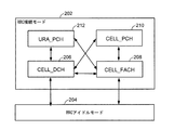
図2は、UEのRRC状態の全般的状態遷移の簡略化された図を示す。UEのRRC状態についての2つの主要状態またはモード、すなわち状態202(「RRC接続モード」としても知られる)、および状態204(「RRCアイドルモード」としても知られる)がある。UE110が、UTRAN102などのネットワークと通信するとき、UE110は、UE110およびRNC106中で実装される無線リソース制御プロトコルによって管理される様々なRRC状態を通る。RRC接続モードにおいて、UE110は、サービングRNCまたはネットワークエンティティを割り当てられ、RRC接続として知られるシグナリング接続を使って、サービングRNCと通信し、ネットワークは、どのセルの中にUE110があるかを知っている。RRCアイドルモードにおいて、UE110はRRC接続をもたず、ネットワークは、どのセルの中にUE110があるかを知らない。
FIG. 2 shows a simplified diagram of the general state transition of the UE's RRC state. There are two main states or modes for the UE's RRC state: state 202 (also known as “RRC connected mode”) and state 204 (also known as “RRC idle mode”). When
図2に示すように、RRC接続モードは、4つの異なる状態、すなわち、CELL_DCH206、CELL_FACH208、CELL_PCH210、およびURA_PCH212を含むことができ、これらは、UEのロケーションと、UEとネットワークとの間の通信のタイプとをネットワークが知っていることに依存する。たとえば、CELL_DCH状態(本明細書では、「セル専用チャネル状態」としても互換的に使われる)において、ネットワークは、ボイス呼およびパケットデータ用の専用チャネル(DCH)を使ってUE110と通信する。つまり、UE110が、トラフィック、たとえば、ボイス呼およびデータ呼用のいずれかの接続を行うとき、UE110およびネットワークは、CELL_DCH状態を確立するか、またはその状態に遷移し、トラフィックの大部分は、この状態において送信され、受信される。CELL_FACH状態(本明細書では、「セルフォワードアクセスチャネル状態」としても互換的に使われる)などの非専用チャネル状態において、ネットワークとUE110は、ランダムアクセスチャネル(RACH)およびフォワードアクセスチャネル(FACH)などの共通トランスポートチャネルを使って通信する。CELL_FACH状態は、シグナリングメッセージおよび少量のパケットデータ用に使われる。したがって、CELL_FACH状態において、UE110は、CELL_DCH状態と比較してはるかに低いデータレートでデータを送り、受信することができる。また、非専用チャネル状態は、CELL_PCHおよびURA_PCH状態を含み得る。CELL_PCH状態において、UE110は、ユーザデータを送ることも受信することもしなくてよく、システム情報およびページング情報を監視し、または受信すればよい。URA_PCHはCELL_PCH状態と同様であり、URA_PCH状態において、UE110がUTRAN登録エリア(URA)境界を横切るとき、UE110は、そのロケーションを更新する。UEのRRC状態遷移のさらに詳細な説明は、参照によって本明細書に組み込まれている3GPP TS25.331において見ることができる。
As shown in FIG. 2, the RRC connection mode can include four different states: CELL_DCH206, CELL_FACH208, CELL_PCH210, and URA_PCH212, which are the location of the UE and the communication between the UE and the network. Depends on the network knowing the type. For example, in CELL_DCH state (also used interchangeably herein as “cell dedicated channel state”), the network communicates with
UE110がどのようにして異なるRRC状態になり得るかをさらに示すために、例示的シナリオを以下に挙げる。UE110のユーザは、インターネット上の特定のウェブページを閲覧したいと仮定する。UE110は、ネットワークとのデータ接続を確立し、ウェブページのコンテンツをUE110上にダウンロードし、その場合、UE110は、データトラフィック(たとえば、ダウンリンクDCHチャネルを介したウェブページのコンテンツ)をネットワークから受信するために、RRCアイドルモードからセル専用チャネル状態(たとえば、CELL_DCH状態)に遷移する。ウェブページのコンテンツがUE110上にダウンロードされた後、ユーザは、ウェブページの閲覧を始める。ユーザがウェブページのコンテンツを閲覧している間、UE110とネットワークとの間にトラフィックがなくてよいことに留意されたい。実際、トラフィックが長時間ない場合がある。UE110のバッテリ消費および臨界リソース(たとえば、DCHチャネル使用)を節約するために、UE110およびネットワークは、RRCアイドルモードにではなく、非専用チャネル状態(たとえば、CELL_FACH状態)に遷移してよい。つまり、UE110は、(たとえば、CELL_FACH状態において)ネットワークへの部分的接続を維持することができるが、電波上にショートデータトラフィックが存在するとき、バッテリおよび臨界リソースを節約する。言い換えると、UE110およびネットワークは、ユーザトラフィックが一定の期間にわたってないときは非専用チャネル状態(たとえば、CELL_FACH)に入り、少量のデータトラフィックのみが存在するときはそこに留まってよい。一定の期間、ユーザトラフィックがないとき、UE110およびネットワークはCELL_PCH状態に切り替わり得る。CELL_DCHからCELL_FACHへの(またはCELL_FACHからCELL_DCHへの)この状態遷移は、UE110上のユーザアプリケーションのタイプおよびUE110とネットワークとの間で転送されるユーザデータの量に依存して、頻繁に起こり得るので、UE110上のバッテリをすぐに消耗させる場合がある。
To further illustrate how
さらに、CELL_DCHからCELL_FACHへの、またはCELL_FACHからCELL_DCHへの状態遷移は概して、UE110によってではなく、ネットワークによってトリガされる。つまり、UE110は、状態遷移に対する直接制御をもたず、他の状態に切り替わるかどうか、およびいつ切り替わるか判断するのは、ネットワークの責任である。ある態様では、本開示は、RRC状態遷移に関するある程度の制御をUEに認めることによって、RRC状態遷移における制限に対処する。
Further, state transitions from CELL_DCH to CELL_FACH or from CELL_FACH to CELL_DCH are generally triggered by the network, not by the
図3は、例として、ネットワークによって開始される、UE110の(たとえば、CELL_DCHからCELL_FACHへの)RRC状態遷移を概念的に示すためのラダー図の例を示す。図3に示す例において、UE110は、301において、RRC状態のうちのセル専用チャネル状態(たとえば、CELL_DCH)で動作しており、ネットワーク102(たとえば、RNC106)は、UEをRRC状態のうちの非専用チャネル状態(たとえば、CELL_FACH)に遷移させることを決めるが、たとえばそれは、ネットワーク102が、ダウンリンク上でユーザトラフィックが欠如していると判断したからである。ネットワーク102は、再構成メッセージ、たとえば、無線ベアラ再構成メッセージ(RB Reconfig msg(DCH→FACH))303)をUE110に送る。CELL_DCH状態から非専用チャネル状態に遷移するよう、UEに指令する再構成メッセージを受信すると、ある態様では、UE110は、次の可能アップリンク送信時間間隔(TTI)中に、複数のレイヤ2肯定応答手順(たとえば、肯定応答をもつ3つまたは4つの状況パケットデータユニット、つまり、STATUS PDU(L2 ACK))をネットワーク102に送る。一実装形態では、UE110は、再構成完了メッセージ、たとえば、無線ベアラ再構成完了メッセージ(RB Reconfig Complete msg(FACH)307)をネットワーク102に随意に送ること、および309においてCELL_FACH状態に入ることによって、複数のレイヤ2肯定応答手順の送信が完了されたすぐ後に、CELL_FACH状態への、UE110のRRC状態の遷移を開始してよい。
FIG. 3 shows an example of a ladder diagram to conceptually illustrate the RRC state transition of UE 110 (eg, from CELL_DCH to CELL_FACH) initiated by the network. In the example shown in FIG. 3,
本明細書に記載される例では、無線ベアラ再構成メッセージ(または、無線ベアラ再構成完了メッセージ)が、本明細書では再構成メッセージ(または、再構成完了メッセージ)の例として与えられるが、他のメッセージも、UEのRRC状態をセル専用チャネル状態から非専用チャネル状態に遷移させるのに使われてよい。つまり、UEについてのRRC状態変化の情報は、無線ベアラ再構成メッセージ以外のメッセージにより、ネットワークから送られてよいが、無線ベアラ再構成メッセージが、そのような目的のために最も一般的に使われるメッセージである。 In the examples described herein, a radio bearer reconfiguration message (or radio bearer reconfiguration completion message) is given here as an example of a reconfiguration message (or reconfiguration completion message), but other These messages may also be used to transition the UE RRC state from the cell dedicated channel state to the non-dedicated channel state. That is, the RRC state change information for the UE may be sent from the network by a message other than the radio bearer reconfiguration message, but the radio bearer reconfiguration message is most commonly used for such purposes. Message.
図3に示す例では、STATUS PDUが、2つのRLCエンティティ(たとえば、UE110およびネットワーク102のRLCエンティティ)の間で状況情報を交換するのに使われる。STATUS PDUはオクテット整列されており、たとえば、長さが8ビットの倍数である。各STATUS PDUは、複数の情報ビット(たとえば、D/Cビット、PDUタイプビット、および1つまたは複数のスーパーフィールド(SUFI)ビットであって、D/Cビットは、そのビットが状況PDUであるかそれとも肯定応答モード(AM)データPDUであるかを示し、PDUタイプビットは制御PDUのタイプを示し、SUFIビットは、肯定応答など、他の状況情報を示す)を含む。
In the example shown in FIG. 3, STATUS PDUs are used to exchange status information between two RLC entities (eg,
さらに、ダウンリンクトラフィックPDUが合間に現れる場合、ネットワーク102が、再構成メッセージ(たとえば、RB Reconfig msg)と再構成完了メッセージ(たとえば、RB Reconfig Complete msg)との間にダウンリンクデータを、またはメッセージの前に、前にスケジュールされたデータのDL再送信をスケジュールするので、UE110は、それらに、305において、STATUS PDUの複数の送信にかかわらず別々に、および/または定期的に肯定応答すればよい。
Further, if a downlink traffic PDU appears in between, the
本開示の別の態様において、ネットワーク102への、第1のSTATUS PDUの送信の後、UE110は、ネットワーク102に第2のSTATUS PDUを送信する前に、一定の期間(または、待機時間)だけ待てばよい。待機時間は、コヒーレンス時間に基づいて算出することができる。「コヒーレンス時間」という言葉は、本明細書では、ワイヤレス通信チャネルのインパルス応答が非変動であると見なされる持続時間を意味するのに使われる。移動オブジェクトについてのコヒーレンス時間は、以下の式を使って決定することができる。
コヒーレンス時間(Tc)=0.423/fd、 (1)
上式で、fdは最大ドップラー周波数に等しい。
In another aspect of the present disclosure, after transmission of the first STATUS PDU to the
Coherence time (Tc) = 0.423 / fd, (1)
Where fd is equal to the maximum Doppler frequency.
たとえば、式(1)を使って、UMTS周波数帯中で信号を送信する、120km/hrで移動しているUE110について、最大ドップラー周波数は、233.3Hzと決定することができる。そのようなケースにおいて、コヒーレンス時間は、1.8ms(Tc=0.423/233.3)と決定され得る。したがって、この例では、UE110は、待機時間を1.8msになるように設定し、第1のSTATUS PDUと同じである第2のSTATUS PDUをネットワーク102に送るのに先立って、ネットワーク102に第1のSTATUS PDUを送った後、待機時間だけ待てばよい。式(1)によると、コヒーレンス時間は、より低帯域のキャリアおよび/またはUE110の低移動速度に対して、より長い期間になる。
For example, using Equation (1), the maximum Doppler frequency can be determined to be 233.3 Hz for
さらに、待機時間は、UE110が受けたUL BLERが無相関であること、およびしたがって単一のディープフェージングがワイヤレス通信システムにおいて克服され得ることを保証するために、STATUS PDUの複数の送信の間で可変的に決定されてよい。たとえば、一実装形態では、1つまたは複数の待機時間が、STATUS PDUの最初の送信と最後の送信との間の時間が約Xミリ秒(ms)になるように決定されてよく、ここでXは、概算的に、ワイヤレス通信システムの速度および搬送周波数に基づくコヒーレンス時間よりも大きい。
In addition, the waiting time is between multiple transmissions of STATUS PDUs to ensure that the UL BLER received by
本開示の別の態様において、UE110は、たとえば、(i)一定の期間にわたって過去に観察されたRRC状態遷移、および/または(ii)他の最近のRLC PDUのUL再送信から観察されるチャネル条件に基づくUL BLERなど、様々な要因に基づいて、STATUS PDUの送信の数を変えることができる。UL BLERが要因として使われると、求められるUL再送信が非常に低くなり得るので、UE110は、STATUS PDUの連続再送信時間を短縮することができる。
In another aspect of the present disclosure, the
本開示において、肯定応答手順は、ダウンリンクにおける、ネットワークからUEへのメッセージ(たとえば、ネットワークからUEへの無線ベアラ再構成メッセージ)の肯定応答のためのRLC L2手順であり、概して、RLC PDUからなる。本開示の別の態様において、RLC L2手順は、2つ以上のRLC PDUを使って実装され得る。さらに、本開示の別の態様において、RLC L2手順は、1つまたは複数のメッセージを使って実装され得る。 In this disclosure, an acknowledgment procedure is an RLC L2 procedure for acknowledgment of a network-to-UE message (e.g., network-to-UE radio bearer reconfiguration message) in the downlink, generally from an RLC PDU. Become. In another aspect of the present disclosure, the RLC L2 procedure may be implemented using two or more RLC PDUs. Further, in another aspect of the present disclosure, the RLC L2 procedure may be implemented using one or more messages.
図4は、本開示の特定の態様による、UEのRRC状態遷移を概念的に示す例示的フローチャートである。ブロック401において、UEがRRC状態のうちのセル専用チャネル状態(たとえば、CELL_DCH)で動作している間、再構成メッセージ(たとえば、無線ベアラ再構成メッセージ)がネットワークから受信され、再構成メッセージは、UEを、RRC状態のうちの、CELL_DCH状態から非専用チャネル状態(たとえば、CELL_FACH)に遷移させるように構成される。たとえば、UE110のRRC状態遷移コンポーネント105(たとえば、受信コンポーネント51)は、UE110がCELL_DCH状態にある間、無線ベアラ再構成メッセージ、たとえば、図3に示すRB Reconfig msg(DCH→FACH)をネットワーク102から受信する。
FIG. 4 is an exemplary flowchart conceptually illustrating UE RRC state transitions according to certain aspects of the present disclosure. At
ブロック403において、UEをCELL_DCH状態から非専用チャネル状態(たとえば、CELL_FACH状態)に遷移させる、受信された再構成メッセージ(たとえば、受信された無線ベアラ再構成メッセージ)に応答して、複数の肯定応答手順がアップリンク上で送られる。たとえば、UE110のRRC状態遷移コンポーネント105(たとえば、送付コンポーネント53)は、UEのRRC状態をCELL_DCHからCELL_FACHに遷移させるための受信された無線ベアラ再構成メッセージに応答して、図3に示す複数のレイヤ2肯定応答手順、たとえば、STATUS PDU(L2 ACK)をネットワーク102に送る。代替として、複数の肯定応答手順は、次の可能UL TTI中に異なる時間間隔で、たとえば、ネットワーク102へのSTATUS PDUの各再送信の間の異なる待機時間に基づいて、ネットワーク102に送られてよい。前に記載したように、待機時間は、UE110によって決定されたコヒーレンス時間に基づき得る。
At
ブロック405において、随意には、複数の肯定応答手順を送った後、UEを非専用チャネル状態(たとえば、CELL_FACH)に遷移させるために、1つまたは複数の他の手順が開始されてよい。たとえば、UE110のRRC状態遷移コンポーネント105(たとえば、送付コンポーネント53)がSTATUS PDUの複数の送信を完了した後、UE110のRRC状態遷移コンポーネント(たとえば、開始コンポーネント55)は、UEのRRC状態をCELL_FACH状態に遷移させるための1つまたは複数の他の手順を開始してよい。
At
ブロック407において、随意に、再構成完了メッセージ(たとえば、無線ベアラ再構成完了メッセージ)がネットワーク102に送られてよい。たとえば、UE110のRRC状態遷移コンポーネント(たとえば、送付コンポーネント53)は、無線ベアラ再構成完了メッセージ(たとえば、図3のRB Reconfig Complete msg)をネットワーク102に送ることができる。
At
図5は、UEまたはノードB/基地局のユーザプレーン502および制御プレーン504に関係する無線プロトコルアーキテクチャ500の例である。たとえば、無線プロトコルアーキテクチャ500は、RRC状態遷移コンポーネント105を有するUE110(図1)などのUE中に含まれ得る。UEおよびノードBの無線プロトコルアーキテクチャ500は、レイヤ1 506、レイヤ2 508、およびレイヤ3 510の3つのレイヤで示されている。レイヤ1 506は最も下のレイヤであり、様々な物理レイヤの信号処理機能を実装する。したがって、レイヤ1 506は、物理レイヤ507を含む。レイヤ2(L2レイヤ)508は、物理レイヤ507の上にあり、物理レイヤ507を通じたUEとノードBとの間のリンクを担当する。レイヤ3(L3レイヤ)510は、無線リソース制御(RRC)サブレイヤ515を含む。RRCサブレイヤ515は、UEとUTRANとの間のレイヤ3の制御プレーンシグナリングを扱う。
FIG. 5 is an example of a
ユーザプレーンでは、L2レイヤ508は、媒体アクセス制御(MAC)サブレイヤ509、無線リンク制御(RLC)サブレイヤ511、およびパケットデータコンバージェンスプロトコル(PDCP)サブレイヤ513を含み、これらはネットワーク側のノードBで終端される。図示されていないが、UEは、ネットワーク側のPDNゲートウェイで終端されるネットワークレイヤ(たとえばIPレイヤ)と、接続の他端(たとえば、遠端のUE、サーバなど)で終端されるアプリケーションレイヤとを含めて、L2レイヤ508の上にいくつかの上位レイヤを有し得る。
In the user plane,
PDCPサブレイヤ513は、異なる無線ベアラと論理チャネルとの多重化を行う。PDCPサブレイヤ513はまた、無線送信のオーバーヘッドを低減するための上位レイヤデータパケットのヘッダ圧縮、データパケットの暗号化によるセキュリティ、および、ノードB間のUEのハンドオーバのサポートを実現する。RLCサブレイヤ511は、上位レイヤのデータパケットのセグメント化および再アセンブリ、紛失したデータパケットの再送信、ならびに、ハイブリッド自動再送要求(HARQ)に起因して順序が乱れた受信を補償するデータパケットの並べ替えを実現する。MACサブレイヤ509は、論理チャネルとトランスポートチャネルとの間の多重化を実現する。MACサブレイヤ509はまた、1つのセルの中の様々な無線リソース(たとえばリソースブロック)をUEの間で割り振ることを担当する。MACサブレイヤ509はまた、HARQ演算を担当する。
The
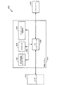
図6は、処理システム614を用いる装置600のためのハードウェア実装の例を概念的に示す図である。この例において、処理システム614は、バス602によって全体的に表されるバスアーキテクチャを用いて実現され得る。バス602は、処理システム614の特定の用途および全体的な設計制約に応じて、任意の数の相互接続するバスおよびブリッジを含む場合がある。バス602は、RRC状態遷移コンポーネント105によって全体的に表される1つまたは複数のRRC状態遷移コンポーネント、プロセッサ604によって全体的に表される1つまたは複数のプロセッサ、およびコンピュータ可読媒体606によって全体的に表されるコンピュータ可読媒体を含む様々な回路を互いにリンクする。バス602は、タイミングソース、周辺装置、電圧調整器、および電力管理回路などの様々な他の回路をリンクすることもできるが、これらの回路は当技術分野でよく知られており、したがってこれ以上は説明しない。バスインターフェース608は、バス602とトランシーバ610との間のインターフェースを実現する。トランシーバ610は、伝送媒体を介して様々な他の装置と通信するための手段を実現する。装置の性質に応じて、ユーザインターフェース612(たとえば、キーパッド、ディスプレイ、スピーカー、マイクロフォン、ジョイスティックなど)も設けられ得る。
FIG. 6 is a diagram conceptually illustrating an example of a hardware implementation for an
プロセッサ604は、バス602を管理することと、コンピュータ可読媒体606上に記憶されたソフトウェアの実行を含む一般的な処理とを担当する。ソフトウェアは、プロセッサ604によって実行されると、任意の特定の装置の以下で説明する様々な機能を処理システム614に実施させる。コンピュータ可読媒体606は、ソフトウェアを実行するときにプロセッサ604によって操作されるデータを記憶するためにも使用され得る。RRC状態遷移コンポーネント105は、本開示の1つまたは複数の態様の実装を担当する。ただし、本開示の1つまたは複数の態様は、RRC状態遷移コンポーネント105、プロセッサ604、コンピュータ可読媒体606、他の制御論理(ハードウェアおよび/またはソフトウェアを含む)、またはどのそれらの組合せによって実装されてもよい。
The
図7を参照すると、UTRANアーキテクチャでのアクセスネットワーク700においてRRC状態遷移コンポーネント105を各々が有する複数のユーザ機器730、732、734、736、738、および740が示されている。多元接続ワイヤレス通信システムは、セル702、704、および706を含む複数のセルラー領域(セル)を含み、セルの各々は、1つまたは複数のセクタを含み得る。複数のセクタは、アンテナのグループによって形成される場合があり、各アンテナはセルの一部分にあるUEとの通信を担当する。たとえば、セル702において、アンテナグループ712、714、および716は各々、異なるセクタに対応し得る。セル704において、アンテナグループ718、720、および722は、各々異なるセクタに対応し得る。セル706において、アンテナグループ724、726、および728は、各々異なるセクタに対応し得る。セル702、704、および706は、各セル702、704、または706の1つまたは複数のセクタと通信していてもよい、いくつかのワイヤレス通信デバイス、たとえばユーザ機器またはUEを含み得る。たとえば、UE730および732は、ノードB742と通信していてもよく、UE734および736は、ノードB744と通信していてもよく、UE738および740は、ノードB746と通信していてもよい。ここで、各ノードB742、744、746は、それぞれのセル702、704、および706の中のすべてのUE730、732、734、736、738、740に、コアネットワーク104(図1参照)へのアクセスポイントを提供するように構成される。
Referring to FIG. 7, a plurality of
UE734がセル704中の図示された位置からセル706に移動するとき、サービングセル変更(SCC)またはハンドオーバが生じて、UE734との通信が、ソースセルと呼ばれることがあるセル704からターゲットセルと呼ばれることがあるセル706に移行し得る。UE734において、それぞれのセルに対応するノードBにおいて、無線ネットワークコントローラ706(図1参照)において、またはワイヤレスネットワークにおける別の適切なノードにおいて、ハンドオーバ手順の管理が行われ得る。たとえば、ソースセル704との呼の間、または任意の他の時間において、UE734は、ソースセル704の様々なパラメータ、ならびに、セル706および702などの近隣セルの様々なパラメータを監視し得る。さらに、これらのパラメータの品質に応じて、UE734は、近隣セルのうちの1つまたは複数との通信を維持することができる。この時間中に、UE734は、UE734が同時に接続されるセルのリストであるアクティブセットを維持し得る(すなわち、ダウンリンク専用物理チャネルDPCHまたはフラクショナルダウンリンク専用物理チャネルF-DPCHをUE734に現在割り当てているUTRAセルが、アクティブセットを構成し得る)。
When UE734 moves from the indicated location in
アクセスネットワーク300によって利用される変調/多元接続方式は、展開されている特定の電気通信規格に応じて異なる場合がある。例として、規格は、エボリューションデータオプティマイズド(EV-DO)またはウルトラモバイルブロードバンド(UMB)を含み得る。EV-DOおよびUMBは、CDMA2000規格ファミリーの一部として第3世代パートナーシッププロジェクト2(3GPP2)によって公表されたエアインターフェース規格であり、CDMAを用いて移動局にブロードバンドインターネットアクセスを提供する。規格は代替的に、広帯域CDMA(W-CDMA)およびTD-SCDMAなどのCDMAの他の変形形態を用いるUniversal Terrestrial Radio Access(UTRA)、TDMAを用いるモバイル通信用グローバルシステム(GSM(登録商標))、ならびにOFDMAを用いる発展型UTRA(E-UTRA)、ウルトラモバイルブロードバンド(UMB)、IEEE 802.11(Wi-Fi)、IEEE 802.16(WiMAX)、IEEE 802.20、およびFlash-OFDMであり得る。UTRA、E-UTRA、UMTS、LTE、LTEアドバンスト、およびGSM(登録商標)は、3GPP団体による文書に記述されている。CDMA2000およびUMBは、3GPP2団体による文書に記述されている。採用される実際のワイヤレス通信規格および多元接続技術は、特定の適用例およびシステムに課された全体的な設計制約に依存する。 The modulation / multiple access scheme utilized by access network 300 may vary depending on the particular telecommunications standard being deployed. By way of example, the standard may include Evolution Data Optimized (EV-DO) or Ultra Mobile Broadband (UMB). EV-DO and UMB are air interface standards published by the 3rd Generation Partnership Project 2 (3GPP2) as part of the CDMA2000 standard family, and provide broadband Internet access to mobile stations using CDMA. The standard is alternatively Universal Terrestrial Radio Access (UTRA) using other variants of CDMA such as Wideband CDMA (W-CDMA) and TD-SCDMA, Global System for Mobile Communications using TDMA (GSM) And evolved UTRA using OFDMA (E-UTRA), Ultra Mobile Broadband (UMB), IEEE 802.11 (Wi-Fi), IEEE 802.16 (WiMAX), IEEE 802.20, and Flash-OFDM. UTRA, E-UTRA, UMTS, LTE, LTE Advanced, and GSM® are described in documents from 3GPP organizations. CDMA2000 and UMB are described in documents from the 3GPP2 organization. The actual wireless communication standard and multiple access technology employed will depend on the specific application and the overall design constraints imposed on the system.
図8は、UE850と通信しているノードB810のブロック図であり、ノードB810は図1のノードB108であってよく、UE850は、RRC状態遷移コンポーネント105を有する図1のUE110であってよい。ダウンリンク通信では、送信プロセッサ820は、データソース812からデータを受信し、コントローラ/プロセッサ840からの制御信号を受信することができる。送信プロセッサ820は、基準信号(たとえばパイロット信号)とともに、データ信号および制御信号のための様々な信号処理機能を提供する。たとえば、送信プロセッサ820は、誤り検出のための巡回冗長検査(CRC)コード、順方向誤り訂正(FEC)を支援するための符号化およびインターリービング、様々な変調方式(たとえば、二位相偏移変調(BPSK)、四位相偏移変調(QPSK)、M-位相偏移変調(M-PSK)、M-直角位相振幅変調(M-QAM)など)に基づいた信号コンステレーションへのマッピング、直交可変拡散率(OVSF)による拡散、および、一連のシンボルを生成するためのスクランブリングコードとの乗算を、提供することができる。チャネルプロセッサ844からのチャネル推定値は、コントローラ/プロセッサ840によって送信プロセッサ820のためのコーディング方式、変調方式、拡散方式、および/またはスクランブリング方式を判断するために使用され得る。これらのチャネル推定値は、UE850によって送信される基準信号から、またはUE850からのフィードバックから導出され得る。送信プロセッサ820によって生成されたシンボルは、フレーム構造を作成するために、送信フレームプロセッサ830に提供される。送信フレームプロセッサ830は、コントローラ/プロセッサ840からの情報を用いてシンボルを多重化することによって、このフレーム構造を作成し、一連のフレームをもたらす。次いで、これらのフレームはトランスミッタ832に与えられ、トランスミッタ832は、アンテナ834を通じたワイヤレス媒体によるダウンリンク送信のために、増幅、フィルタリング、およびフレームのキャリア上への変調を含む、様々な信号調整機能を提供する。アンテナ834は、たとえば、ビームステアリング双方向適応アンテナアレイまたは他の同様のビーム技術を含む、1つまたは複数のアンテナを含み得る。
FIG. 8 is a block diagram of a
UE850において、レシーバ854は、アンテナ852を通じてダウンリンク送信を受信し、その送信を処理してキャリア上に変調された情報を復元する。レシーバ854によって復元された情報は、受信フレームプロセッサ860に与えられ、受信フレームプロセッサ860は、各フレームをパースし、フレームからの情報をチャネルプロセッサ894に与え、データ信号、制御信号、および基準信号を受信プロセッサ870に与える。受信プロセッサ870は、次いで、ノードB810において送信プロセッサ820によって実施される処理の逆を実施する。より具体的には、受信プロセッサ870は、シンボルをデスクランブルし、逆拡散し、次いで、変調方式に基づいてノードB810によって送信された最も可能性が高い信号コンスタレーションを決定する。これらの軟判定は、チャネルプロセッサ894によって計算されたチャネル推定値に基づいている場合がある。次いで、軟判定は、データ信号、制御信号、および基準信号を復元するために、復号およびデインターリーブされる。CRCコードは、次いで、フレームが正常に復号されたかどうかを決定するためにチェックされる。次いで、復号に成功したフレームによって搬送されたデータがデータシンク872に与えられ、データシンク872は、UE850および/または様々なユーザインターフェース(たとえば、ディスプレイ)において稼働しているアプリケーションを表す。復号に成功したフレームによって搬送された制御信号は、コントローラ/プロセッサ890に与えられる。フレームがレシーバプロセッサ870によって正常に復号されないとき、コントローラ/プロセッサ890は、これらのフレームのための再送信要求をサポートするために、肯定応答(ACK)および/または否定応答(NACK)プロトコルを使用することもできる。
In
アップリンクでは、データソース878からのデータおよびコントローラ/プロセッサ890からの制御信号が、送信プロセッサ880に提供される。データソース878は、UE850内で稼働中のアプリケーションと、様々なユーザインターフェース(たとえば、キーボード)とを表すことができる。ノードB810によるダウンリンク送信に関して説明した機能と同様に、送信プロセッサ880は、CRCコード、FECを容易にするためのコーディングおよびインターリービング、信号コンスタレーションへのマッピング、OVSFによる拡散、ならびに、一連のシンボルを生成するためのスクランブリングを含む、様々な信号処理機能を提供する。ノードB810によって送信される基準信号から、または、ノードB810によって送信されるミッドアンブル中に含まれるフィードバックから、チャネルプロセッサ494によって導出されるチャネル推定値が、適切なコーディング方式、変調方式、拡散方式、および/またはスクランブリング方式を選択するために使用され得る。送信プロセッサ880によって生成されたシンボルは、フレーム構造を作成するために、送信フレームプロセッサ882に提供される。送信フレームプロセッサ882は、コントローラ/プロセッサ890からの情報を用いてシンボルを多重化することによって、このフレーム構造を作成し、一連のフレームをもたらす。次いで、これらのフレームはトランスミッタ856に与えられ、トランスミッタ856は、アンテナ852を通じたワイヤレス媒体によるアップリンク送信のために、増幅、フィルタリング、およびフレームのキャリア上への変調を含む、様々な信号調整機能を提供する。
On the uplink, data from data source 878 and control signals from controller /
アップリンク送信は、UE850においてレシーバ機能に関して説明されたのと同様の方式で、ノードB810において処理される。レシーバ835は、アンテナ834を通してアップリンク送信を受信し、この送信を処理してキャリア上に変調された情報を復元する。レシーバ835によって復元された情報は、受信フレームプロセッサ836に与えられ、受信フレームプロセッサ836は、各フレームを解析し、フレームからの情報をチャネルプロセッサ844に与え、データと、制御および基準信号とを受信プロセッサ838に与える。受信プロセッサ838は、UE850において送信プロセッサ880によって実施される処理の逆を実施する。次いで、復号に成功したフレームによって搬送されたデータ信号および制御信号が、データシンク839およびコントローラ/プロセッサにそれぞれ与えられ得る。フレームのいくつかが受信プロセッサによって正常に復号されなかった場合、コントローラ/プロセッサ840は、これらのフレームのための再送要求をサポートするために、肯定応答(ACK)および/または否定応答(NACK)プロトコルを使用することもできる。
The uplink transmission is processed at
コントローラ/プロセッサ840および890は、それぞれノードB810およびUE850における動作を指示するために使用され得る。たとえば、コントローラ/プロセッサ840および890は、タイミング、周辺インターフェース、電圧調整、電源管理、および他の制御機能を含む、様々な機能を提供することができる。メモリ842および892のコンピュータ可読媒体は、それぞれノードB810用およびUE850用のデータとソフトウェアとを記憶することができる。ノードB810におけるスケジューラ/プロセッサ846は、UEにリソースを割り当て、UEのためのダウンリンク送信および/またはアップリンク送信をスケジュールするために使用され得る。
Controllers /
電気通信システムのいくつかの態様が、HSPAシステムを参照して提示されてきた。当業者なら容易に了解するように、本開示全体にわたって説明した様々な態様は、他の電気通信システム、ネットワークアーキテクチャ、および通信規格に拡張され得る。 Several aspects of telecommunications systems have been presented with reference to HSPA systems. As will be readily appreciated by those skilled in the art, the various aspects described throughout this disclosure can be extended to other telecommunications systems, network architectures, and communication standards.
例として、様々な態様は、W-CDMA、TD-SCDMA、高速ダウンリンクパケットアクセス(HSDPA)、高速アップリンクパケットアクセス(HSUPA)、高速パケットアクセスプラス(HSPA+)、およびTD-CDMAなどの、他のUMTSシステムに拡張され得る。様々な態様はまた、(FDD、TDD、または両方のモードの)ロングタームエボリューション(LTE)、(FDD、TDD、または両方のモードの)LTEアドバンスト(LTE-A)、CDMA2000、エボリューションデータオプティマイズド(EV-DO)、ウルトラモバイルブロードバンド(UMB)、IEEE802.11(Wi-Fi)、IEEE802.16(WiMAX)、IEEE802.20、ウルトラワイドバンド(UWB)、Bluetooth(登録商標)、および/または他の適切なシステムを利用するシステムに拡張され得る。用いられる実際の電気通信規格、ネットワークアーキテクチャ、および/または通信規格は、特定の適用例およびシステムに課された全体的な設計制約に依存する。 By way of example, various aspects include other such as W-CDMA, TD-SCDMA, High Speed Downlink Packet Access (HSDPA), High Speed Uplink Packet Access (HSUPA), High Speed Packet Access Plus (HSPA +), and TD-CDMA. Can be extended to UMTS systems. Various aspects also include Long Term Evolution (LTE) (for FDD, TDD, or both modes), LTE Advanced (LTE-A) (for FDD, TDD, or both modes), CDMA2000, Evolution Data Optimized (for EV-DO), Ultra Mobile Broadband (UMB), IEEE802.11 (Wi-Fi), IEEE802.16 (WiMAX), IEEE802.20, Ultra Wideband (UWB), Bluetooth®, and / or other It can be extended to systems that use appropriate systems. The actual telecommunication standard, network architecture, and / or communication standard used will depend on the specific application and the overall design constraints imposed on the system.
本開示の様々な態様によれば、要素または要素の一部分または要素の組合せは、1つまたは複数のプロセッサを含む「処理システム」を用いて実装され得る。プロセッサの例としては、マイクロプロセッサ、マイクロコントローラ、デジタル信号プロセッサ(DSP)、フィールドプログラマブルゲートアレイ(FPGA)、プログラマブル論理デバイス(PLD)、ステートマシン、ゲート論理、個別ハードウェア回路、および本開示全体にわたって説明される様々な機能を実施するように構成された他の適切なハードウェアがある。処理システム内の1つまたは複数のプロセッサは、ソフトウェアを実行し得る。ソフトウェアは、ソフトウェア、ファームウェア、ミドルウェア、マイクロコード、ハードウェア記述言語と呼ばれるか、または他の名称で呼ばれるかどうかにかかわらず、命令、命令セット、コード、コードセグメント、プログラムコード、プログラム、サブプログラム、ソフトウェアモジュール、アプリケーション、ソフトウェアアプリケーション、ソフトウェアパッケージ、ルーチン、サブルーチン、オブジェクト、実行可能ファイル、実行スレッド、プロシージャ、機能などを意味するように広く解釈されるべきである。ソフトウェアは、コンピュータ可読媒体上に存在し得る。コンピュータ可読媒体は、非一時的コンピュータ可読媒体であり得る。非一時的コンピュータ可読媒体は、例として、磁気記憶デバイス(たとえば、ハードディスク、フロッピー(登録商標)ディスク、磁気ストリップ)、光ディスク(たとえば、コンパクトディスク(CD)、デジタル多目的ディスク(DVD))、スマートカード、フラッシュメモリデバイス(たとえば、カード、スティック、キードライブ)、ランダムアクセスメモリ(RAM)、読取り専用メモリ(ROM)、プログラマブルROM(PROM)、消去可能PROM(EPROM)、電気的消去可能PROM(EEPROM)、レジスタ、取り外し可能ディスク、ならびに、コンピュータがアクセスしかつ読み取ることができるソフトウェアおよび/または命令を記憶するための任意の他の適切な媒体を含む。コンピュータ可読媒体には、例として、搬送波、送信路、ならびに、コンピュータがアクセスし読み取ることができるソフトウェアおよび/または命令を送信するための任意の他の適切な媒体も含まれ得る。コンピュータ可読媒体は、処理システム中に存在し、処理システムの外部に存在し、または処理システムを含む複数のエンティティにわたって分散され得る。コンピュータ可読媒体は、コンピュータプログラム製品において具体化され得る。例として、コンピュータプログラム製品は、パッケージング材料内のコンピュータ可読媒体を含み得る。当業者は、特定の適用例およびシステム全体に課された全体的な設計制約に応じて、本開示全体にわたって提示する説明した機能をどのようにして最善の形で実装するかを認識されよう。 According to various aspects of the disclosure, an element or a portion of an element or combination of elements may be implemented using a “processing system” that includes one or more processors. Examples of processors include microprocessors, microcontrollers, digital signal processors (DSPs), field programmable gate arrays (FPGAs), programmable logic devices (PLDs), state machines, gate logic, discrete hardware circuits, and throughout this disclosure There are other suitable hardware configured to perform the various functions described. One or more processors in the processing system may execute software. Software, whether referred to as software, firmware, middleware, microcode, hardware description language, or other names, instructions, instruction sets, code, code segments, program codes, programs, subprograms, It should be interpreted broadly to mean software modules, applications, software applications, software packages, routines, subroutines, objects, executables, threads of execution, procedures, functions, etc. The software may be on a computer readable medium. The computer readable medium may be a non-transitory computer readable medium. Non-transitory computer readable media include, by way of example, magnetic storage devices (eg, hard disks, floppy disks, magnetic strips), optical disks (eg, compact disks (CDs), digital versatile disks (DVDs)), smart cards Flash memory devices (e.g. cards, sticks, key drives), random access memory (RAM), read only memory (ROM), programmable ROM (PROM), erasable PROM (EPROM), electrically erasable PROM (EEPROM) , Registers, removable disks, and any other suitable medium for storing software and / or instructions that can be accessed and read by a computer. Computer-readable media may also include, by way of example, a carrier wave, a transmission path, and any other suitable medium for transmitting software and / or instructions that can be accessed and read by a computer. The computer readable medium may reside in the processing system, be external to the processing system, or be distributed across multiple entities that include the processing system. The computer readable medium may be embodied in a computer program product. By way of example, a computer program product may include a computer readable medium in packaging material. Those skilled in the art will recognize how best to implement the described functionality presented throughout this disclosure, depending on the particular application and the overall design constraints imposed on the overall system.
開示した方法におけるステップの特定の順序または階層は例示的なプロセスの一例であることを理解されたい。設計上の選好に基づいて、方法におけるステップの特定の順序または階層は、並べ替えられ得ることを理解されたい。付随の方法の請求項は、サンプルの順序で様々なステップの要素を示し、本明細書に特に定めがない限り、示された特定の順序または階層に限定されることは意味していない。 It should be understood that the specific order or hierarchy of steps in the disclosed methods is an example of an exemplary process. It should be understood that based on design preferences, a particular order or hierarchy of steps in the method may be rearranged. The accompanying method claims present elements of the various steps in a sample order, and are not meant to be limited to the specific order or hierarchy presented unless specifically stated herein.
前述の説明は、いかなる当業者も本明細書で説明する様々な態様を実施することを可能にするように与えられる。これらの態様に対する様々な修正は当業者には容易に明らかであり、本明細書に定義された一般的な原理は他の態様に適用され得る。したがって、特許請求の範囲は本明細書で示す態様に限定されるよう意図されているわけではなく、特許請求の範囲の文言と整合するすべての範囲を許容するように意図されており、単数の要素への言及は、そのように明記されていない限り、「唯一無二の」ではなく、「1つまたは複数の」を意味するよう意図されている。別段に明記されていない限り、「いくつかの」という用語は「1つまたは複数の」を指す。項目のリスト「のうちの少なくとも1つ」という句は、単一のメンバーを含め、それらの項目の任意の組合せを指す。一例として、「a、bまたはcのうちの少なくとも1つ」は、aと、bと、cと、aおよびbと、aおよびcと、bおよびcと、a、bおよびcとを包含するように意図されている。当業者に知られている、または後に知られるようになる、本開示全体にわたって説明する様々な態様の要素の構造的および機能的な均等物のすべては、参照により本明細書に明確に組み込まれ、特許請求の範囲によって包含されるように意図されている。さらに、本明細書で開示するいかなる内容も、そのような開示が特許請求の範囲で明示的に記載されているかどうかにかかわらず、公に供することは意図されていない。請求項のいかなる要素も、「のための手段」という句を使用して要素が明示的に記載されていない限り、または方法の請求項の場合に「のためのステップ」という句を使用して要素が記載されていない限り、米国特許法第112条第6項または米国特許法第112条(f)の規定に基づいて解釈されるべきではない。
The previous description is provided to enable any person skilled in the art to implement the various aspects described herein. Various modifications to these aspects will be readily apparent to those skilled in the art, and the generic principles defined herein may be applied to other aspects. Thus, the claims are not intended to be limited to the embodiments shown herein, but are intended to allow the full scope to be consistent with the language of the claims. Reference to an element is intended to mean "one or more", not "one and only", unless so specified. Unless otherwise specified, the term “several” refers to “one or more”. The phrase “at least one of the list of items” refers to any combination of those items, including a single member. As an example, “at least one of a, b, or c” includes a, b, c, a and b, a and c, b and c, a, b and c. Is intended to be. All structural and functional equivalents of the elements of the various aspects described throughout this disclosure, known to those skilled in the art or later become known, are expressly incorporated herein by reference. And is intended to be encompassed by the claims. Moreover, nothing disclosed herein is intended to be publicly available regardless of whether such disclosure is expressly recited in the claims. Any element of a claim uses the phrase “step for” unless the element is explicitly stated using the phrase “means for” or in the case of a method claim. Unless elements are listed, they should not be construed in accordance with the provisions of 35
51 受信コンポーネント
53 送付コンポーネント
55 開始コンポーネント
100 UMTSシステム
102 UMTS陸上無線アクセスネットワーク(UTRAN)
104 コアネットワーク(CN)
105 無線リソース制御(RRC)状態遷移コンポーネント
106 無線ネットワークコントローラ(RNC)
107 無線ネットワークサブシステム(RNS)
108 ノードB
110 ユーザ機器(UE)
111 汎用加入者識別モジュール(USIM)
112 MSC
114 GMSC
115 ホームロケーションレジスタ(HLR)
116 回路交換ネットワーク
118 サービングGPRSサポートノード(SGSN)
120 ゲートウェイGPRSサポートノード(GGSN)
122 パケットベースネットワーク
202 状態
204 状態
206 CELL_DCH
208 CELL_FACH
210 CELL_PCH
212 URA_PCH
300 アクセスネットワーク
303 無線ベアラ再構成メッセージ
307 無線ベアラ再構成完了メッセージ
494 チャネルプロセッサ
500 無線プロトコルアーキテクチャ、アーキテクチャ
502 ユーザプレーン
504 制御プレーン
506 レイヤ1
507 物理レイヤ
508 レイヤ2(L2レイヤ)
509 媒体アクセス制御(MAC)サブレイヤ
510 レイヤ3(L3レイヤ)
511 無線リンク制御(RLC)サブレイヤ
513 パケットデータコンバージェンスプロトコル(PDCP)サブレイヤ
515 無線リソース制御(RRC)サブレイヤ
600 装置
602 バス
604 プロセッサ
606 コンピュータ可読媒体
608 バスインターフェース
610 トランシーバ
612 ユーザインターフェース
614 処理システム
700 アクセスネットワーク
702 セル
704 セル
706 セル
712 アンテナグループ
714 アンテナグループ
716 アンテナグループ
724 アンテナグループ
726 アンテナグループ
728 アンテナグループ
730 UE
732 UE
734 UE
736 UE
738 UE
740 UE
742 ノードB
744 ノードB
746 ノードB
810 ノードB
812 データソース
820 送信プロセッサ
830 送信フレームプロセッサ
832 トランスミッタ
834 アンテナ
835 レシーバ
836 受信フレームプロセッサ
838 受信プロセッサ
839 データシンク
840 コントローラ/プロセッサ
842 メモリ
844 チャネルプロセッサ
846 スケジューラ/プロセッサ
850 UE
852 アンテナ
854 レシーバ
856 トランスミッタ
860 受信フレームプロセッサ
870 受信プロセッサ、レシーバプロセッサ
878 データソース
880 送信プロセッサ
872 データシンク
890 コントローラ/プロセッサ
892 メモリ
894 チャネルプロセッサ
51 Receiving component
53 Shipping components
55 Starting component
100 UMTS system
102 UMTS Terrestrial Radio Access Network (UTRAN)
104 Core network (CN)
105 Radio Resource Control (RRC) state transition component
106 Radio network controller (RNC)
107 Radio Network Subsystem (RNS)
108 Node B
110 User equipment (UE)
111 Universal Subscriber Identification Module (USIM)
112 MSC
114 GMSC
115 Home Location Register (HLR)
116 Circuit switching network
118 Serving GPRS Support Node (SGSN)
120 Gateway GPRS Support Node (GGSN)
122 packet-based network
202 state
204 states
206 CELL_DCH
208 CELL_FACH
210 CELL_PCH
212 URA_PCH
300 access network
303 Radio bearer reconfiguration message
307 Radio bearer reconfiguration complete message
494 channel processor
500 wireless protocol architecture, architecture
502 user plane
504 Control plane
506
507 Physical layer
508 Layer 2 (L2 layer)
509 Medium Access Control (MAC) sublayer
510 Layer 3 (L3 layer)
511 Radio Link Control (RLC) sublayer
513 Packet Data Convergence Protocol (PDCP) sublayer
515 Radio Resource Control (RRC) sublayer
600 devices
602 bus
604 processor
606 Computer-readable medium
608 bus interface
610 transceiver
612 User interface
614 treatment system
700 access network
702 cells
704 cells
706 cells
712 Antenna group
714 Antenna group
716 Antenna group
724 Antenna group
726 Antenna group
728 Antenna group
730 UE
732 UE
734 UE
736 UE
738 UE
740 UE
742 Node B
744 Node B
746 Node B
810 Node B
812 data source
820 transmit processor
830 Transmit frame processor
832 transmitter
834 Antenna
835 receiver
836 Receive frame processor
838 Receive processor
839 Data sync
840 controller / processor
842 memory
844 channel processor
846 Scheduler / Processor
850 UE
852 antenna
854 receiver
856 transmitter
860 receive frame processor
870 receiver processor, receiver processor
878 data sources
880 transmit processor
872 Data Sync
890 controller / processor
892 memory
894 channel processor
Claims (15)
前記UEが前記RRC状態のうちのセル専用チャネル(CELL_DCH)状態にある間に、ネットワークから再構成メッセージを受信するステップであって、前記再構成メッセージは、前記UEを、前記RCC状態のうちの前記CELL_DCH状態から非専用チャネル状態に遷移させるように構成される、ステップと、
前記UEを、前記RRC状態のうちの前記CELL_DCH状態から、前記RRC状態のうちの前記非専用チャネル状態に遷移させる、前記受信された再構成メッセージに応答して、複数の肯定応答手順をアップリンク上で前記ネットワークに送るステップとを含み、
前記複数の肯定応答手順の数は、前記UEの以前のRRC状態遷移に少なくとも基づいて判断され、
前記複数の肯定応答手順の各々は状況パケットデータユニットを含み、前記状況パケットデータユニットは、前記ネットワークからの前記受信された再構成メッセージの肯定応答情報を含む、方法。 A method for transitioning a radio resource control (RRC) state of a user equipment (UE) for wireless communication,
Receiving a reconfiguration message from a network while the UE is in a cell dedicated channel (CELL_DCH) state of the RRC state, the reconfiguration message indicating the UE of the RCC state; Configured to transition from the CELL_DCH state to a non-dedicated channel state; and
Uplink a plurality of acknowledgment procedures in response to the received reconfiguration message that causes the UE to transition from the CELL_DCH state of the RRC state to the non-dedicated channel state of the RRC state. and sending to the network above only contains,
The number of acknowledgment procedures is determined based at least on previous RRC state transitions of the UE;
Each of the plurality of acknowledgment procedures includes a status packet data unit, the status packet data unit including acknowledgment information of the received reconfiguration message from the network .
前記UEが前記RRC状態のうちのセル専用チャネル(CELL_DCH)状態にある間に、ネットワークから再構成メッセージを受信するための手段であって、前記再構成メッセージは、前記UEを、前記RCC状態のうちの前記CELL_DCH状態から非専用チャネル状態に遷移させるように構成される、手段と、
前記UEを、前記RRC状態のうちの前記CELL_DCH状態から、前記RRC状態のうちの前記非専用チャネル状態に遷移させる、前記受信された再構成メッセージに応答して、複数の肯定応答手順をアップリンク上で前記ネットワークに送るための手段とを備え、
前記複数の肯定応答手順の数は、前記UEの以前のRRC状態遷移に少なくとも基づいて判断され、
前記複数の肯定応答手順の各々は状況パケットデータユニットを含み、前記状況パケットデータユニットは、前記ネットワークからの前記受信された再構成メッセージの肯定応答情報を含む、装置。 An apparatus for transitioning a radio resource control (RRC) state of a user equipment (UE) for wireless communication,
Means for receiving a reconfiguration message from a network while the UE is in a cell dedicated channel (CELL_DCH) state of the RRC state, wherein the reconfiguration message indicates that the UE is in the RCC state. Means configured to transition from the CELL_DCH state to a non-dedicated channel state;
Uplink a plurality of acknowledgment procedures in response to the received reconfiguration message that causes the UE to transition from the CELL_DCH state of the RRC state to the non-dedicated channel state of the RRC state. Means for sending to the network above ,
The number of acknowledgment procedures is determined based at least on previous RRC state transitions of the UE;
The apparatus wherein each of the plurality of acknowledgment procedures includes a status packet data unit, the status packet data unit including acknowledgment information of the received reconfiguration message from the network .
ユーザ機器(UE)が、無線リソース制御(RRC)状態のうちのセル専用チャネル(CELL_DCH)状態にある間に、ネットワークから再構成メッセージを受信するためのコードであって、前記再構成メッセージは、前記UEを、前記RCC状態のうちの前記CELL_DCH状態から非専用チャネル状態に遷移させるように構成される、コードと、
前記UEを、前記RRC状態のうちの前記CELL_DCH状態から、前記RRC状態のうちの前記非専用チャネル状態に遷移させる、前記受信された再構成メッセージに応答して、複数の肯定応答手順をアップリンク上で前記ネットワークに送るためのコードとを備え、
前記複数の肯定応答手順の数は、前記UEの以前のRRC状態遷移に少なくとも基づいて判断され、
前記複数の肯定応答手順の各々は状況パケットデータユニットを含み、前記状況パケットデータユニットは、前記ネットワークからの前記受信された再構成メッセージの肯定応答情報を含む、コンピュータ可読記憶媒体。 A computer readable storage medium storing computer executable code comprising:
While the user equipment (UE) is in the cell dedicated channel (CELL_DCH) state of the radio resource control (RRC) state, it is a code for receiving a reconfiguration message from the network, wherein the reconfiguration message is A code configured to transition the UE from the CELL_DCH state of the RCC state to a non-dedicated channel state;
Uplink a plurality of acknowledgment procedures in response to the received reconfiguration message that causes the UE to transition from the CELL_DCH state of the RRC state to the non-dedicated channel state of the RRC state. A code for sending to the network above ,
The number of acknowledgment procedures is determined based at least on previous RRC state transitions of the UE;
Each of the plurality of acknowledgment procedures includes a status packet data unit, the status packet data unit including acknowledgment information of the received reconfiguration message from the network .
Applications Claiming Priority (5)
| Application Number | Priority Date | Filing Date | Title |
|---|---|---|---|
| US201461941260P | 2014-02-18 | 2014-02-18 | |
| US61/941,260 | 2014-02-18 | ||
| US14/470,350 | 2014-08-27 | ||
| US14/470,350 US9544942B2 (en) | 2014-02-18 | 2014-08-27 | DCH to non-DCH state switching of user equipment in UMTS |
| PCT/US2015/015553 WO2015126714A1 (en) | 2014-02-18 | 2015-02-12 | Dch to non-dch state switching of user equipment in umts |
Publications (3)
| Publication Number | Publication Date |
|---|---|
| JP2017506844A JP2017506844A (en) | 2017-03-09 |
| JP2017506844A5 JP2017506844A5 (en) | 2018-03-08 |
| JP6434041B2 true JP6434041B2 (en) | 2018-12-05 |
Family
ID=53799375
Family Applications (1)
| Application Number | Title | Priority Date | Filing Date |
|---|---|---|---|
| JP2016551148A Expired - Fee Related JP6434041B2 (en) | 2014-02-18 | 2015-02-12 | User equipment state switching from DCH to non-DCH in UMTS |
Country Status (6)
| Country | Link |
|---|---|
| US (1) | US9544942B2 (en) |
| EP (1) | EP3108704B1 (en) |
| JP (1) | JP6434041B2 (en) |
| KR (1) | KR20160122241A (en) |
| CN (1) | CN106105331B (en) |
| WO (1) | WO2015126714A1 (en) |
Families Citing this family (6)
| Publication number | Priority date | Publication date | Assignee | Title |
|---|---|---|---|---|
| US10142970B2 (en) * | 2014-05-05 | 2018-11-27 | Nokia Solutions And Networks Oy | RLC reconfiguration during cell reselection |
| WO2015190986A1 (en) * | 2014-06-10 | 2015-12-17 | Telefonaktiebolaget L M Ericsson (Publ) | Methods and arrangements for switching of states |
| WO2017182845A1 (en) * | 2016-04-21 | 2017-10-26 | Telefonaktiebolaget Lm Ericsson (Publ) | Status detection of rrc connection |
| US10291356B2 (en) * | 2016-05-11 | 2019-05-14 | Futurewei Technologies, Inc. | Decoding procedures in systems with codeblock segmentation |
| CN110493823B (en) * | 2016-08-15 | 2020-09-04 | 华为技术有限公司 | Data processing method and device |
| US10904941B2 (en) * | 2017-07-30 | 2021-01-26 | Lg Electronics Inc. | Method and apparatus for resuming RRC connection in CU-DU division scenario |
Family Cites Families (16)
| Publication number | Priority date | Publication date | Assignee | Title |
|---|---|---|---|---|
| KR100382470B1 (en) * | 1999-04-08 | 2003-05-01 | 엘지전자 주식회사 | Radio Protocol in IMT-2000 Mobile Communication System |
| US7406065B2 (en) * | 2002-03-14 | 2008-07-29 | Qualcomm, Incorporated | Method and apparatus for reducing inter-channel interference in a wireless communication system |
| US7184792B2 (en) * | 2004-02-10 | 2007-02-27 | Qualcomm Incorporated | Delayed data transmission in a wireless communication system after physical layer reconfiguration |
| CN100425101C (en) * | 2005-10-13 | 2008-10-08 | 大唐移动通信设备有限公司 | Method for improving user apparatus state transition speed |
| US7693519B2 (en) * | 2006-07-14 | 2010-04-06 | M-Stack Limited | Method and apparatus for reducing link interference by a link between a user equipment component and an access network component |
| KR101381475B1 (en) | 2007-04-13 | 2014-04-04 | 삼성전자주식회사 | Method of transiting RRC state into IDLE state of user equipment and system therefor and the user equipment |
| US7925233B2 (en) * | 2007-07-20 | 2011-04-12 | Htc Corporation | Methods for handling measurement reports in a wireless communication system |
| MY154139A (en) * | 2008-02-04 | 2015-05-15 | Ericsson Telefon Ab L M | Methods and arrangements in a wireless communications system for controlling the timing of a user equipment entering in an uplink transmission procedure |
| CA2742800C (en) * | 2008-11-04 | 2017-07-04 | Nortel Networks Limited | Providing acknowledgment information by a wireless device |
| CN101860906B (en) * | 2009-04-10 | 2013-04-24 | 电信科学技术研究院 | Method and system for determining data transmission format in state transfer process |
| CN101938800A (en) * | 2009-06-30 | 2011-01-05 | 华为技术有限公司 | Information transmitting method, information receiving method and device |
| US20110194433A1 (en) * | 2010-02-05 | 2011-08-11 | Qualcomm Incorporated | Managing dedicated channel resource allocation to user equipment based on radio bearer traffic within a wireless communications system |
| US8185116B2 (en) * | 2010-02-10 | 2012-05-22 | Htc Corporation | Methods and system for handling proximity indication and detection in a wireless communication system |
| US8447291B2 (en) * | 2011-04-14 | 2013-05-21 | Qualcomm Incorporated | Selective state transitions of a user equipment within a wireless communications system |
| KR101841687B1 (en) * | 2011-11-07 | 2018-03-27 | 주식회사 팬택 | Apparatus and method for controling in-device coexistence interference in wireless communication system |
| US9049657B2 (en) * | 2011-11-11 | 2015-06-02 | Blackberry Limited | System and method of user equipment state transition |
-
2014
- 2014-08-27 US US14/470,350 patent/US9544942B2/en active Active
-
2015
- 2015-02-12 EP EP15710615.4A patent/EP3108704B1/en not_active Not-in-force
- 2015-02-12 KR KR1020167025385A patent/KR20160122241A/en not_active Application Discontinuation
- 2015-02-12 CN CN201580008858.5A patent/CN106105331B/en not_active Expired - Fee Related
- 2015-02-12 WO PCT/US2015/015553 patent/WO2015126714A1/en active Application Filing
- 2015-02-12 JP JP2016551148A patent/JP6434041B2/en not_active Expired - Fee Related
Also Published As
| Publication number | Publication date |
|---|---|
| KR20160122241A (en) | 2016-10-21 |
| US9544942B2 (en) | 2017-01-10 |
| US20150237672A1 (en) | 2015-08-20 |
| CN106105331B (en) | 2019-08-02 |
| JP2017506844A (en) | 2017-03-09 |
| EP3108704B1 (en) | 2017-11-29 |
| EP3108704A1 (en) | 2016-12-28 |
| WO2015126714A1 (en) | 2015-08-27 |
| CN106105331A (en) | 2016-11-09 |
Similar Documents
| Publication | Publication Date | Title |
|---|---|---|
| JP5827444B2 (en) | Method and apparatus for data throughput optimization in a DSDS scenario | |
| TWI450607B (en) | Systems and methods of maintaining core network status during serving radio network subsystem relocation | |
| JP6140193B2 (en) | Apparatus and method for communicating via multiple subscriptions | |
| JP5596242B2 (en) | Apparatus and method for using page cycle learning mode | |
| JP5933819B2 (en) | Apparatus and method for scheduling cell broadcast messages | |
| JP6434041B2 (en) | User equipment state switching from DCH to non-DCH in UMTS | |
| JP6240792B2 (en) | Improved timer handling mechanism | |
| WO2013149015A1 (en) | Method and apparatus for supporting tune away in dual-sim dual standby mobile devices | |
| TWI573431B (en) | Method and apparatus for utilizing the smart blanking feature of thermal mitigation in telecommunication | |
| JP6378188B2 (en) | Apparatus and method for delaying cell update messages from user equipment | |
| WO2014047933A1 (en) | Method and apparatus for rrc message combining | |
| JP2016515353A (en) | Method and apparatus for improving retransmission of reconfigured messages | |
| JP5795123B2 (en) | Apparatus and method for maintaining circuit switched voice calls in a multi-RAB wireless communication system in an area with low coverage | |
| WO2015126707A1 (en) | Enhanced polling for security mode procedures | |
| JP2016525300A (en) | Apparatus and method for dynamic user equipment capability reporting based on data activity | |
| JP2015535159A (en) | Method and apparatus for downlink / uplink flow control in HSPA + UE using autonomous connection DRX mode triggering | |
| EP3008848B1 (en) | Methods and apparatus for improving call performance and data throughput | |
| EP2918105B1 (en) | Method and apparatus to reduce signaling spikes when moving between wlan and wwan coverage areas | |
| JP2017518669A (en) | Synchronization in radio link control (RLC) layer entities | |
| US20150119038A1 (en) | Method and apparatus for cell reselection during serving radio network subsystem (srns) relocation |
Legal Events
| Date | Code | Title | Description |
|---|---|---|---|
| A521 | Request for written amendment filed |
Free format text: JAPANESE INTERMEDIATE CODE: A523 Effective date: 20180124 |
|
| A621 | Written request for application examination |
Free format text: JAPANESE INTERMEDIATE CODE: A621 Effective date: 20180124 |
|
| TRDD | Decision of grant or rejection written | ||
| A01 | Written decision to grant a patent or to grant a registration (utility model) |
Free format text: JAPANESE INTERMEDIATE CODE: A01 Effective date: 20181015 |
|
| A61 | First payment of annual fees (during grant procedure) |
Free format text: JAPANESE INTERMEDIATE CODE: A61 Effective date: 20181107 |
|
| R150 | Certificate of patent or registration of utility model |
Ref document number: 6434041 Country of ref document: JP Free format text: JAPANESE INTERMEDIATE CODE: R150 |
|
| LAPS | Cancellation because of no payment of annual fees |