JP6433357B2 - Boundary microphone - Google Patents
Boundary microphone Download PDFInfo
- Publication number
- JP6433357B2 JP6433357B2 JP2015063829A JP2015063829A JP6433357B2 JP 6433357 B2 JP6433357 B2 JP 6433357B2 JP 2015063829 A JP2015063829 A JP 2015063829A JP 2015063829 A JP2015063829 A JP 2015063829A JP 6433357 B2 JP6433357 B2 JP 6433357B2
- Authority
- JP
- Japan
- Prior art keywords
- unit
- microphone
- boundary
- switch
- air pressure
- Prior art date
- Legal status (The legal status is an assumption and is not a legal conclusion. Google has not performed a legal analysis and makes no representation as to the accuracy of the status listed.)
- Expired - Fee Related
Links
Images


Classifications
-
- H—ELECTRICITY
- H04—ELECTRIC COMMUNICATION TECHNIQUE
- H04R—LOUDSPEAKERS, MICROPHONES, GRAMOPHONE PICK-UPS OR LIKE ACOUSTIC ELECTROMECHANICAL TRANSDUCERS; DEAF-AID SETS; PUBLIC ADDRESS SYSTEMS
- H04R1/00—Details of transducers, loudspeakers or microphones
- H04R1/02—Casings; Cabinets ; Supports therefor; Mountings therein
- H04R1/04—Structural association of microphone with electric circuitry therefor
-
- H—ELECTRICITY
- H04—ELECTRIC COMMUNICATION TECHNIQUE
- H04R—LOUDSPEAKERS, MICROPHONES, GRAMOPHONE PICK-UPS OR LIKE ACOUSTIC ELECTROMECHANICAL TRANSDUCERS; DEAF-AID SETS; PUBLIC ADDRESS SYSTEMS
- H04R29/00—Monitoring arrangements; Testing arrangements
- H04R29/004—Monitoring arrangements; Testing arrangements for microphones
Landscapes
- Physics & Mathematics (AREA)
- Engineering & Computer Science (AREA)
- Acoustics & Sound (AREA)
- Signal Processing (AREA)
- Health & Medical Sciences (AREA)
- General Health & Medical Sciences (AREA)
- Otolaryngology (AREA)
- Details Of Audible-Bandwidth Transducers (AREA)
Description
本発明は、バウンダリーマイクロホンに関する。 The present invention relates to a boundary microphone.
会議用のマイクロホンの中には、机上に載置して収音するバウンダリーマイクロホンがある。バウンダリーマイクロホンの中には、話者がマイクロホンのスイッチを操作する機能を備えたものがあるが、このスイッチを操作するときに発生する音と操作時の振動がバウンダリーマイクロホン内のマイクロホンユニットに伝わると雑音が発生してしまう。これまでにも、この雑音の発生を防止するためにメンブレンスイッチを用いるなどした提案がなされている(例えば、特許文献1参照)。 Among conference microphones, there is a boundary microphone that is placed on a desk and picks up sound. Some boundary microphones have a function that allows a speaker to operate a switch on the microphone, but the sound generated when operating this switch and the vibration during operation are transmitted to the microphone unit in the boundary microphone. If it is transmitted, noise will be generated. In the past, proposals have been made such as using a membrane switch to prevent the generation of this noise (see, for example, Patent Document 1).
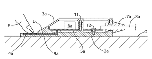
図4は、従来のバウンダリーマイクロホンの縦断面図である。
バウンダリーマイクロホンは、ベース2aとカバー3aとボタン4aと回路基板5aとマイクロホンユニット6aとを有してなる。
FIG. 4 is a longitudinal sectional view of a conventional boundary microphone.
The boundary microphone includes a
ベース2aは、金属製で、上面側(紙面上側)が開放された扁平状である。カバー3aは、金属製で、多数の音波導入孔を備え、ベース2aの開放部分を覆う。ボタン4aは、ゴム等の弾性部材を用いた支持部材を介して、ベース2aに形成された凹部に支持固定されている。ボタン4aは、操作者の指Fにより押下されると、ベース2aの凹部内に沈み、指Fからの押圧が解除されると、押下前の位置に復帰する。
The
バウンダリーマイクロホンは、机など載置面Gに載置されている。カバー3aは、雄ネジT1によりベース2aに固定されている。
The boundary microphone is placed on a placement surface G such as a desk. The
ベース2aのボタン4aが配置された側の反対側(紙面右側)には、コードブッシュ7aが設けられている。コードブッシュ7aには、マイクロホンケーブル8aが挿通されている。
A cord bush 7a is provided on the opposite side (the right side of the drawing) of the
ベース2aとカバー3aとで形成されるバウンダリーマイクロホンの内部の空間には、回路基板5aと、マイクロホンユニット6aと、が収納されている。
A
回路基板5aは、ネジT2によりベース2aに固定されている。回路基板5aの一端には、マイクロホンケーブル8aが電気的に接続されている。マイクロホンケーブル8aの他端は、コードブッシュ7aを介してベース2aから引き出されている。
The
回路基板5aは、マイクロホンユニット6aが出力した電気信号を処理して音声信号を生成する各種の回路を実装する。回路基板5aが生成した音声信号は、マイクロホンケーブル8aを介して、外部の音声信号の処理装置に出力される。
The
マイクロホンユニット6aは、例えば、カバー3aの音波導入孔を通ってきた音波を受けて振動板が振動し、コンデンサを構成する前記振動板と固定極との間の静電容量の変化を電気信号に変換して出力するコンデンサマイクロホンユニットである。
The
ボタン4aは、例えば、感圧スイッチで、メンブレンと回路基板とで構成されている。ボタン4aのメンブレンと回路基板は、回路基板のパターン形成部がメンブレンを向いてベース2aに取り付けられている。ボタン4aは、回路基板のパターンとメンブレンとが接触するとオンになる。ベース2aには、ボタン4aの回路基板と、回路基板5aとの間に、空間9aが設けられている。フレキシブルプリント基板Lからなるボタン4aの回路基板は、そのフレキシブルプリント基板Lを空間9aに挿通させて回路基板5aと電気的に接続していて、ボタン4aの押下操作はフレキシブルプリント基板Lを介して回路基板5aに伝達される。
The
ここで、バウンダリーマイクロホンのスイッチの操作時の雑音発生の原因には、帯電した人体がスイッチに近接あるいは接触することで発生する火花放電がある。この火花放電は、パッシェンの法則に従い、帯電した人体とスイッチを構成する導体との間で発生する。したがって、この火花放電の発生は、絶縁フィルム等でスイッチを覆うことで抑制される。 Here, the cause of noise generation when the switch of the boundary microphone is operated is spark discharge generated when a charged human body approaches or comes into contact with the switch. This spark discharge is generated between a charged human body and a conductor constituting the switch according to Paschen's law. Therefore, the occurrence of this spark discharge is suppressed by covering the switch with an insulating film or the like.
しかし、人体の帯電量が大きいときには、絶縁層を破壊して火花放電が発生してしまう。図中、破線で示す導体(フレキシブルプリント基板L)があることで、放電電流がバウンダリーマイクロホンの内部に流れ込んで雑音を発生させる。したがって、スイッチ部には、バウンダリーマイクロホンの内部に引き込まれる導体が無いことが望ましい。 However, when the charge amount of the human body is large, the insulating layer is destroyed and spark discharge occurs. In the figure, since there is a conductor (flexible printed circuit board L) indicated by a broken line, a discharge current flows into the boundary microphone to generate noise. Therefore, it is desirable that the switch section has no conductor drawn into the boundary microphone.
本発明は、以上のような従来技術の問題点を解消するためになされたもので、スイッチ操作時に火花放電が発生しないバウンダリーマイクロホンを提供することを目的とする。 The present invention has been made to solve the above-described problems of the prior art, and an object of the present invention is to provide a boundary microphone that does not generate a spark discharge when a switch is operated.
本発明は、マイクロホンユニットと、マイクロホンユニットの出力信号をオン・オフさせるスイッチ部と、を有してなり、スイッチ部は、空気室と、空気室の空気圧に基づいてオン・オフを制御する制御部と、を備えることを特徴とする。 The present invention includes a microphone unit and a switch unit that turns on and off an output signal of the microphone unit, and the switch unit controls on / off based on the air chamber and the air pressure of the air chamber. And a section.
本発明によれば、スイッチ操作時に火花放電が発生しない。 According to the present invention, no spark discharge occurs during switch operation.
以下、図面を参照しながら、本発明にかかるバウンダリーマイクロホンの実施の形態について説明する。 Hereinafter, embodiments of a boundary microphone according to the present invention will be described with reference to the drawings.
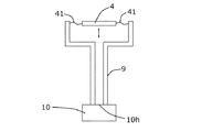
図1は、本発明にかかるバウンダリーマイクロホンの実施の形態を示す外観図である。バウンダリーマイクロホン1は、ベース2とカバー3とボタン4とを有してなる。
FIG. 1 is an external view showing an embodiment of a boundary microphone according to the present invention. The boundary microphone 1 includes a
ベース2は、金属製で、上面側(紙面上側)が開放された扁平状である。ベース2は、例えば、亜鉛ダイカストなどの鋳造品により形成されてもよいし、あるいは、別の金属のプレス成型品を用いてもよい。
The
カバー3は、金属製で、多数の音波導入孔を備え、ベース2の開放部分を覆う。カバー3は、例えば、鉄板などの金属板に多数の孔を形成したパンチングプレート(多孔板)を用いてもよいし、あるいは、金網状のものを用いてもよい。
The
ボタン4は、ゴム等の弾性部材を用いた支持部材を介して、ベース2に形成された凹部に支持固定されている。ボタン4は、操作者の指Fにより押下されると、ベース2の凹部内に沈み、指Fからの押圧が解除されると、押下前の位置に復帰する。
The
図2は、バウンダリーマイクロホン1の縦断面図である。
バウンダリーマイクロホン1は、机など載置面Gに載置されている。カバー3は、雄ネジS1によりベース2に固定されている。
FIG. 2 is a longitudinal sectional view of the boundary microphone 1.
The boundary microphone 1 is placed on a placement surface G such as a desk. The
ベース2のボタン4が配置された側の反対側(紙面右側)には、コードブッシュ7が設けられている。コードブッシュ7には、マイクロホンケーブル8が挿通されている。
A
ベース2とカバー3とで形成されるバウンダリーマイクロホン1の内部の空間には、回路基板5と、マイクロホンユニット6と、が収納されている。
A
回路基板5は、ネジS2によりベース2に固定されている。回路基板5の一端には、マイクロホンケーブル8が電気的に接続されている。マイクロホンケーブル8の他端は、コードブッシュ7を介してベース2から引き出されている。
The
回路基板5は、後述するマイクロホンユニット6が出力した電気信号を処理して音声信号を生成する各種の回路を実装する。回路基板5が生成した音声信号は、マイクロホンケーブル8を介して、外部の音声信号の処理装置に出力される。
The
マイクロホンユニット6は、例えば、コンデンサマイクロホンユニットである。この場合、マイクロホンユニット6は、カバー3の音波導入孔を通ってきた音波を受けて振動板が振動し、コンデンサを構成する前記振動板と固定極との間の静電容量の変化を電気信号に変換して出力する。
The
なお、マイクロホンユニット6は、回路基板5に実装された状態でバウンダリーマイクロホン1の内部の空間に収納されてもよいし、回路基板5とは別にして同空間に収納されてもよい。
Note that the
次に、マイクロホンユニット6の出力信号をオン・オフさせるスイッチ部について説明する。
図3は、バウンダリーマイクロホン1のスイッチ部の構造を示す模式図である。スイッチ部は、ボタン4と管9と検出部10とコンパレータ(不図示)とスイッチ回路(不図示)とで構成される。
Next, a switch unit for turning on / off the output signal of the
FIG. 3 is a schematic diagram showing the structure of the switch part of the boundary microphone 1. The switch unit includes a
ボタン4は、ベース2のマイクロホンユニット6から離間した先端部分に取り付けられる。ボタン4と検出部10とは、ベース2内に設けられた空気室としての中空状の管9で繋がっている。すなわち、ボタン4は管9の一端に配置され、検出部10は管9の他端に配置されている。操作部としてのボタン4は、弾性部材で形成された支持部材41により、ベース2の凹部内を移動可能(紙面上下方向)に支持固定されている。ボタン4に対する操作は、例えば、操作者の指Fでの押圧操作などの手動操作がある。検出部10は、マイクロホンユニット6と回路基板5とが収納されているベース2内に取り付けられる。管9は、マイクロホンユニット6とボタン4との間に存在するベース2内に平面方向に沿って形成された両者を連通する連通孔により構成される。
The
スイッチ部を構成するコンパレータとスイッチ回路とは、ボタン4の押圧操作に応じて変化する管9の空気圧に基づいてマイクロホンユニット6の出力信号をオン・オフさせる制御部として機能する。制御部としてのコンパレータとスイッチ回路とは、回路基板5に実装される。
The comparator and the switch circuit constituting the switch unit function as a control unit that turns on and off the output signal of the
制御部は、回路基板5がマイクロホンユニット6からの電気信号を処理して生成した音声信号をマイクロホンケーブル8に出力するか否かを制御する。すなわち、例えば、制御部は、ボタン4が押されている間、回路基板5が生成した音声信号をマイクロホンケーブル8に出力し、ボタン4が押されていないときには、回路基板5が生成した音声信号をマイクロホンケーブル8に出力しない。あるいは、制御部は、ボタン4が押されるごとに、回路基板5が生成した音声信号のマイクロホンケーブル8への出力を開始したり停止したりするように構成してもよい。
The control unit controls whether or not the
検出部10は、管9の空気圧を検出または管9の空気圧の変化を検出して、検出結果を制御部に出力する。つまり、検出部10は空気圧の絶対値を検出したり、空気圧の(単位時間当たりの)変化量を検出する。
The
検出部10は、例えば、マイクロホンユニット6とは別のコンデンサマイクロホンユニット(以下、「検出ユニット」という。)で構成されている。検出ユニット10は、有底筒状のユニットケースと、ユニットケース内に収納されたコンデンサを構成する振動板と固定極とを備える。振動板は、片面に金属(好ましくは金)蒸着膜を有する円板状の合成樹脂の薄膜フィルムである。固定極は、金属製で、円板状である。固定極の少なくとも一面側、例えば、振動板との対向面側にはエレクトレット板が貼り付けられて、エレクトレットボードを構成する。このユニットケースと振動板と固定極とにより、検出ユニット10のコンデンサマイクロホンユニットが構成される。
The
検出ユニット10のユニットケースの底面には、音孔10hが設けられている。検出ユニット10は、音孔10hを通る空気の空気圧で振動板が振動する。管9の一端と検出ユニット10のユニットケースの音孔10hとが位置合わせされて、管9と検出ユニット10とはベース2内に配置固定されている。検出ユニット10の振動板は、管9内の空気の空気圧に応じて振動する。すなわち、検出ユニット10の振動板と固定極とで構成されるコンデンサの静電容量は、管9内の空気の空気圧の変化に応じて変化する。検出ユニット10は、管9内の空気の空気圧に応じた電気信号を生成して、コンパレータに出力する。
A
なお、ボタン4が押下され続けたとしても、時間の経過と共に検出ユニット10の振動板がボタン4の押下前の位置に復帰するように、管9の一部に孔を設けてもよい。
Even if the
コンパレータは、検出ユニット10が出力した電気信号を、予めコンパレータに設定されている閾値信号と比較する。検出ユニット10が出力した電気信号が閾値信号より大きいとき、すなわち、ボタン4が押下されて管9内の空気の空気圧が所定の空気圧よりも大きくなったとき、コンパレータは制御信号を生成してスイッチ回路に出力する。
The comparator compares the electric signal output from the
スイッチ回路は、コンパレータから制御信号を受信すると、スイッチの開閉を行う。制御信号は、スイッチの閉鎖または開放をスイッチ回路に指示する信号である。スイッチが閉鎖されると、回路基板5により生成された音声信号がマイクロホンケーブル8に出力される。スイッチが開放されると、回路基板5により生成された音声信号がマイクロホンケーブル8に出力されない。
When receiving a control signal from the comparator, the switch circuit opens and closes the switch. The control signal is a signal that instructs the switch circuit to close or open the switch. When the switch is closed, the audio signal generated by the
このように、ボタン4が押下されて管9内の空気の空気圧が所定の空気圧よりも大きくなったときには、スイッチが閉鎖されて、回路基板5により生成された音声信号がマイクロホンケーブル8に出力される。一方、ボタン4が押下されず管9内の空気の空気圧が所定の空気圧よりも小さいときには、スイッチが開放されて、回路基板5により生成された音声信号はマイクロホンケーブル8に出力されない。
In this way, when the
なお、制御部は、スイッチの開閉制御を、管9内の空気圧の変化量に応じて実現してもよい。この場合、スイッチの開閉制御は、ボタン4の押圧操作や解除操作の速度に応じて実現される。
The control unit may realize switch opening / closing control in accordance with the amount of change in air pressure in the
以上説明した実施の形態によれば、バウンダリーマイクロホン1は、ボタン4の押下操作を管9内の空気の空気圧で検出することができる。すなわち、バウンダリーマイクロホン1のスイッチ部は、バウンダリーマイクロホン1の内部に引き込まれる導体が無いため、スイッチ操作時の火花放電は発生しない。その結果、バウンダリーマイクロホン1は、放電電流がバウンダリーマイクロホン1の内部に流れ込んで雑音を発生させることはない。
According to the embodiment described above, the boundary microphone 1 can detect the pressing operation of the
なお、管9の内径と長さとを適切に設計、例えば、管9の内径を2mm以下、管9の長さを20mm以上とすることで、音声信号以下の周波数のみが検出ユニット10に伝達されるため、音声信号でスイッチ部が誤動作するのを防止することができる。
In addition, by appropriately designing the inner diameter and length of the
1 バウンダリーマイクロホン
2 ベース
3 カバー
4 ボタン
41 支持部材
5 回路基板
6 マイクロホンユニット
7 コードブッシュ
8 マイクロホンケーブル
9 管
10 検出部
10h 音孔
S1 雄ネジ
S2 ネジ
DESCRIPTION OF SYMBOLS 1
Claims (9)
前記マイクロホンユニットの出力信号をオン・オフさせるスイッチ部と、
を有してなり、
前記スイッチ部は、
空気室と、
前記空気室の空気圧に基づいて前記オン・オフを制御する制御部と、
を備える、
ことを特徴とするバウンダリーマイクロホン。 A microphone unit,
A switch unit for turning on and off the output signal of the microphone unit;
Having
The switch part is
An air chamber,
A control unit for controlling the on / off based on the air pressure of the air chamber;
Comprising
Boundary microphone characterized by that.
請求項1記載のバウンダリーマイクロホン。 A detector for detecting the air pressure of the air chamber;
The boundary microphone according to claim 1.
前記空気圧に応じて振動する振動板と、前記振動板と共にコンデンサを構成する固定極と、を備え、
前記振動板と前記固定極との間の静電容量の変化に基づいて前記空気圧を検出する、
請求項2記載のバウンダリーマイクロホン。 The detector is
A diaphragm that vibrates in accordance with the air pressure; and a fixed pole that constitutes a capacitor together with the diaphragm,
Detecting the air pressure based on a change in capacitance between the diaphragm and the fixed pole;
The boundary microphone according to claim 2 .
前記制御部は、前記コンデンサマイクロホンユニットからの出力信号に基づいて前記オン・オフを制御する、
請求項2または3記載のバウンダリーマイクロホン。 The detection unit is composed of a condenser microphone unit,
The control unit controls the on / off based on an output signal from the condenser microphone unit.
The boundary microphone according to claim 2 or 3 .
を備える、
請求項2乃至4のいずれかに記載のバウンダリーマイクロホン。 An operation unit for changing the air pressure;
Comprising
The boundary microphone according to any one of claims 2 to 4.
請求項5記載のバウンダリーマイクロホン。 The air pressure is changed by a pressing operation of the operation unit.
The boundary microphone according to claim 5.
請求項6記載のバウンダリーマイクロホン。 The pressing operation is performed manually.
The boundary microphone according to claim 6.
前記操作部は、前記管の一端に配置され、
前記検出部は、前記管の他端に配置される、
請求項5乃至7のいずれかに記載のバウンダリーマイクロホン。 The air chamber is configured by a hollow tube that connects the operation unit and the detection unit,
The operation unit is disposed at one end of the tube,
The detector is disposed at the other end of the tube.
The boundary microphone according to claim 5.
を備え、
前記スイッチ部は、前記マイクロホンユニットから離間して前記ベースに取り付けられ、
前記管は、前記ベースに形成された前記マイクロホンユニットと前記スイッチ部とを連通する連通孔である、
請求項8記載のバウンダリーマイクロホン。 A base for storing the microphone unit;
With
The switch unit is attached to the base apart from the microphone unit,
The tube is a communication hole that communicates the microphone unit formed on the base and the switch unit.
The boundary microphone according to claim 8.
Priority Applications (2)
| Application Number | Priority Date | Filing Date | Title |
|---|---|---|---|
| JP2015063829A JP6433357B2 (en) | 2015-03-26 | 2015-03-26 | Boundary microphone |
| US15/078,365 US9872096B2 (en) | 2015-03-26 | 2016-03-23 | Boundary microphone |
Applications Claiming Priority (1)
| Application Number | Priority Date | Filing Date | Title |
|---|---|---|---|
| JP2015063829A JP6433357B2 (en) | 2015-03-26 | 2015-03-26 | Boundary microphone |
Publications (2)
| Publication Number | Publication Date |
|---|---|
| JP2016184845A JP2016184845A (en) | 2016-10-20 |
| JP6433357B2 true JP6433357B2 (en) | 2018-12-05 |
Family
ID=56974468
Family Applications (1)
| Application Number | Title | Priority Date | Filing Date |
|---|---|---|---|
| JP2015063829A Expired - Fee Related JP6433357B2 (en) | 2015-03-26 | 2015-03-26 | Boundary microphone |
Country Status (2)
| Country | Link |
|---|---|
| US (1) | US9872096B2 (en) |
| JP (1) | JP6433357B2 (en) |
Families Citing this family (3)
| Publication number | Priority date | Publication date | Assignee | Title |
|---|---|---|---|---|
| JP6595310B2 (en) * | 2015-11-17 | 2019-10-23 | 株式会社オーディオテクニカ | Boundary microphone |
| CN110428799B (en) | 2019-07-08 | 2020-09-29 | 维沃移动通信有限公司 | Terminal device |
| CN112291692B (en) * | 2020-10-13 | 2022-01-28 | 皓骏科技(北京)有限公司 | Detection device |
Family Cites Families (20)
| Publication number | Priority date | Publication date | Assignee | Title |
|---|---|---|---|---|
| US4382159A (en) * | 1981-05-29 | 1983-05-03 | Bowditch Robert S | Blow actuated microphone |
| JP2998759B1 (en) * | 1999-03-25 | 2000-01-11 | ヤマハ株式会社 | Vibration detector, self-utterance detector and hearing aid |
| US6684174B2 (en) * | 2002-02-27 | 2004-01-27 | Radioshack, Corp. | Wind gauge |
| US7136500B2 (en) * | 2003-08-05 | 2006-11-14 | Knowles Electronics, Llc. | Electret condenser microphone |
| US20100287799A1 (en) * | 2009-05-13 | 2010-11-18 | Timothy Clegg | Microphone air sensor card |
| JP5432597B2 (en) * | 2009-06-01 | 2014-03-05 | 株式会社オーディオテクニカ | Boundary microphone and desktop electroacoustic transducer |
| JP5534822B2 (en) | 2010-01-08 | 2014-07-02 | 株式会社オーディオテクニカ | Boundary microphone |
| JP5425710B2 (en) * | 2010-05-28 | 2014-02-26 | 株式会社オーディオテクニカ | Boundary microphone |
| EP2432249A1 (en) * | 2010-07-02 | 2012-03-21 | Knowles Electronics Asia PTE. Ltd. | Microphone |
| JP5610903B2 (en) * | 2010-07-30 | 2014-10-22 | 株式会社オーディオテクニカ | Electroacoustic transducer |
| CN104507384A (en) * | 2012-07-30 | 2015-04-08 | 三菱化学控股株式会社 | Subject information detection unit, subject information processing device, electric toothbrush device, electric shaver device, subject information detection device, aging degree evaluation method, and aging degree evaluation device |
| US8833171B2 (en) * | 2012-08-23 | 2014-09-16 | Nxp, B.V. | Pressure sensor |
| US8872015B2 (en) * | 2012-08-27 | 2014-10-28 | Avedis Zildjian Co. | Cymbal transducer using electret accelerometer |
| US9809448B2 (en) * | 2013-03-13 | 2017-11-07 | Invensense, Inc. | Systems and apparatus having MEMS acoustic sensors and other MEMS sensors and methods of fabrication of the same |
| US20150041930A1 (en) * | 2013-08-09 | 2015-02-12 | Samsung Electro-Mechanics Co., Ltd. | Acoustic transducer |
| KR102056287B1 (en) * | 2013-11-27 | 2019-12-16 | 한국전자통신연구원 | Microphone |
| US8731186B1 (en) * | 2013-12-10 | 2014-05-20 | Vysk Communications, Inc. | Microphone disruption apparatus and method |
| US8724020B1 (en) * | 2013-12-10 | 2014-05-13 | Vysk Communications, Inc. | Microphone and camera disruption apparatus and method |
| US9877510B2 (en) * | 2014-04-04 | 2018-01-30 | Rai Strategic Holdings, Inc. | Sensor for an aerosol delivery device |
| US9671300B2 (en) * | 2015-03-16 | 2017-06-06 | Apple Inc. | Electronic devices with low-noise pressure sensors |
-
2015
- 2015-03-26 JP JP2015063829A patent/JP6433357B2/en not_active Expired - Fee Related
-
2016
- 2016-03-23 US US15/078,365 patent/US9872096B2/en not_active Expired - Fee Related
Also Published As
| Publication number | Publication date |
|---|---|
| US20160286293A1 (en) | 2016-09-29 |
| US9872096B2 (en) | 2018-01-16 |
| JP2016184845A (en) | 2016-10-20 |
Similar Documents
| Publication | Publication Date | Title |
|---|---|---|
| US7233674B2 (en) | Integrated base and electret condenser microphone using the same | |
| JP5808284B2 (en) | Unidirectional condenser microphone | |
| JP6433357B2 (en) | Boundary microphone | |
| JP6511281B2 (en) | Microphone device | |
| US4516428A (en) | Acceleration vibration detector | |
| US8199943B2 (en) | Hearing apparatus with automatic switch-off and corresponding method | |
| US8588452B2 (en) | Microphone cap and microphone | |
| JP5492036B2 (en) | Gooseneck microphone | |
| US7263194B2 (en) | Hearing device | |
| JP7149585B2 (en) | Electroacoustic transducer and electroacoustic transducer | |
| JP5534822B2 (en) | Boundary microphone | |
| TWI433551B (en) | Condenser microphone | |
| JP6421313B2 (en) | Microphone device | |
| JP6210597B2 (en) | Condenser microphone | |
| JP6355155B2 (en) | Condenser microphone | |
| US20090034749A1 (en) | Hearing Apparatus with a Moveable Charging Contact | |
| JP2010161738A (en) | Non-directional condenser microphone unit and non-directional condenser microphone | |
| JP6633953B2 (en) | Microphone | |
| JP5410333B2 (en) | Unidirectional condenser microphone | |
| EP3370432B1 (en) | Cylindrical contact-type microphone | |
| JP4649365B2 (en) | Condenser microphone | |
| JP5203166B2 (en) | Electret condenser microphone system | |
| US20100220880A1 (en) | Hearing aid comprising parts made of electrically conductive and simultaneously sound-absorbent material | |
| JP2008166907A (en) | Preattenuator for condenser microphone and condenser microphone | |
| JP5453001B2 (en) | Unidirectional condenser microphone |
Legal Events
| Date | Code | Title | Description |
|---|---|---|---|
| A621 | Written request for application examination |
Free format text: JAPANESE INTERMEDIATE CODE: A621 Effective date: 20171211 |
|
| A977 | Report on retrieval |
Free format text: JAPANESE INTERMEDIATE CODE: A971007 Effective date: 20180914 |
|
| A131 | Notification of reasons for refusal |
Free format text: JAPANESE INTERMEDIATE CODE: A131 Effective date: 20181012 |
|
| A521 | Request for written amendment filed |
Free format text: JAPANESE INTERMEDIATE CODE: A523 Effective date: 20181022 |
|
| TRDD | Decision of grant or rejection written | ||
| A01 | Written decision to grant a patent or to grant a registration (utility model) |
Free format text: JAPANESE INTERMEDIATE CODE: A01 Effective date: 20181102 |
|
| A61 | First payment of annual fees (during grant procedure) |
Free format text: JAPANESE INTERMEDIATE CODE: A61 Effective date: 20181106 |
|
| R150 | Certificate of patent or registration of utility model |
Ref document number: 6433357 Country of ref document: JP Free format text: JAPANESE INTERMEDIATE CODE: R150 |
|
| LAPS | Cancellation because of no payment of annual fees |