JP6432110B2 - gas turbine - Google Patents
gas turbine Download PDFInfo
- Publication number
- JP6432110B2 JP6432110B2 JP2014175185A JP2014175185A JP6432110B2 JP 6432110 B2 JP6432110 B2 JP 6432110B2 JP 2014175185 A JP2014175185 A JP 2014175185A JP 2014175185 A JP2014175185 A JP 2014175185A JP 6432110 B2 JP6432110 B2 JP 6432110B2
- Authority
- JP
- Japan
- Prior art keywords
- passage
- cooling air
- blade row
- rotor shaft
- stage
- Prior art date
- Legal status (The legal status is an assumption and is not a legal conclusion. Google has not performed a legal analysis and makes no representation as to the accuracy of the status listed.)
- Active
Links
Images


Classifications
-
- F—MECHANICAL ENGINEERING; LIGHTING; HEATING; WEAPONS; BLASTING
- F01—MACHINES OR ENGINES IN GENERAL; ENGINE PLANTS IN GENERAL; STEAM ENGINES
- F01D—NON-POSITIVE DISPLACEMENT MACHINES OR ENGINES, e.g. STEAM TURBINES
- F01D5/00—Blades; Blade-carrying members; Heating, heat-insulating, cooling or antivibration means on the blades or the members
- F01D5/02—Blade-carrying members, e.g. rotors
- F01D5/08—Heating, heat-insulating or cooling means
- F01D5/081—Cooling fluid being directed on the side of the rotor disc or at the roots of the blades
- F01D5/084—Cooling fluid being directed on the side of the rotor disc or at the roots of the blades the fluid circulating at the periphery of a multistage rotor, e.g. of drum type
-
- F—MECHANICAL ENGINEERING; LIGHTING; HEATING; WEAPONS; BLASTING
- F01—MACHINES OR ENGINES IN GENERAL; ENGINE PLANTS IN GENERAL; STEAM ENGINES
- F01D—NON-POSITIVE DISPLACEMENT MACHINES OR ENGINES, e.g. STEAM TURBINES
- F01D25/00—Component parts, details, or accessories, not provided for in, or of interest apart from, other groups
- F01D25/08—Cooling; Heating; Heat-insulation
- F01D25/12—Cooling
-
- F—MECHANICAL ENGINEERING; LIGHTING; HEATING; WEAPONS; BLASTING
- F01—MACHINES OR ENGINES IN GENERAL; ENGINE PLANTS IN GENERAL; STEAM ENGINES
- F01D—NON-POSITIVE DISPLACEMENT MACHINES OR ENGINES, e.g. STEAM TURBINES
- F01D5/00—Blades; Blade-carrying members; Heating, heat-insulating, cooling or antivibration means on the blades or the members
- F01D5/02—Blade-carrying members, e.g. rotors
- F01D5/08—Heating, heat-insulating or cooling means
- F01D5/085—Heating, heat-insulating or cooling means cooling fluid circulating inside the rotor
-
- F—MECHANICAL ENGINEERING; LIGHTING; HEATING; WEAPONS; BLASTING
- F01—MACHINES OR ENGINES IN GENERAL; ENGINE PLANTS IN GENERAL; STEAM ENGINES
- F01D—NON-POSITIVE DISPLACEMENT MACHINES OR ENGINES, e.g. STEAM TURBINES
- F01D9/00—Stators
- F01D9/06—Fluid supply conduits to nozzles or the like
- F01D9/065—Fluid supply or removal conduits traversing the working fluid flow, e.g. for lubrication-, cooling-, or sealing fluids
-
- F—MECHANICAL ENGINEERING; LIGHTING; HEATING; WEAPONS; BLASTING
- F02—COMBUSTION ENGINES; HOT-GAS OR COMBUSTION-PRODUCT ENGINE PLANTS
- F02C—GAS-TURBINE PLANTS; AIR INTAKES FOR JET-PROPULSION PLANTS; CONTROLLING FUEL SUPPLY IN AIR-BREATHING JET-PROPULSION PLANTS
- F02C6/00—Plural gas-turbine plants; Combinations of gas-turbine plants with other apparatus; Adaptations of gas- turbine plants for special use
- F02C6/04—Gas-turbine plants providing heated or pressurised working fluid for other apparatus, e.g. without mechanical power output
- F02C6/06—Gas-turbine plants providing heated or pressurised working fluid for other apparatus, e.g. without mechanical power output providing compressed gas
- F02C6/08—Gas-turbine plants providing heated or pressurised working fluid for other apparatus, e.g. without mechanical power output providing compressed gas the gas being bled from the gas-turbine compressor
-
- F—MECHANICAL ENGINEERING; LIGHTING; HEATING; WEAPONS; BLASTING
- F02—COMBUSTION ENGINES; HOT-GAS OR COMBUSTION-PRODUCT ENGINE PLANTS
- F02C—GAS-TURBINE PLANTS; AIR INTAKES FOR JET-PROPULSION PLANTS; CONTROLLING FUEL SUPPLY IN AIR-BREATHING JET-PROPULSION PLANTS
- F02C7/00—Features, components parts, details or accessories, not provided for in, or of interest apart form groups F02C1/00 - F02C6/00; Air intakes for jet-propulsion plants
- F02C7/12—Cooling of plants
- F02C7/16—Cooling of plants characterised by cooling medium
- F02C7/18—Cooling of plants characterised by cooling medium the medium being gaseous, e.g. air
- F02C7/185—Cooling means for reducing the temperature of the cooling air or gas
-
- F—MECHANICAL ENGINEERING; LIGHTING; HEATING; WEAPONS; BLASTING
- F01—MACHINES OR ENGINES IN GENERAL; ENGINE PLANTS IN GENERAL; STEAM ENGINES
- F01D—NON-POSITIVE DISPLACEMENT MACHINES OR ENGINES, e.g. STEAM TURBINES
- F01D5/00—Blades; Blade-carrying members; Heating, heat-insulating, cooling or antivibration means on the blades or the members
- F01D5/12—Blades
- F01D5/14—Form or construction
- F01D5/18—Hollow blades, i.e. blades with cooling or heating channels or cavities; Heating, heat-insulating or cooling means on blades
-
- F—MECHANICAL ENGINEERING; LIGHTING; HEATING; WEAPONS; BLASTING
- F05—INDEXING SCHEMES RELATING TO ENGINES OR PUMPS IN VARIOUS SUBCLASSES OF CLASSES F01-F04
- F05D—INDEXING SCHEME FOR ASPECTS RELATING TO NON-POSITIVE-DISPLACEMENT MACHINES OR ENGINES, GAS-TURBINES OR JET-PROPULSION PLANTS
- F05D2260/00—Function
- F05D2260/20—Heat transfer, e.g. cooling
- F05D2260/213—Heat transfer, e.g. cooling by the provision of a heat exchanger within the cooling circuit
-
- Y—GENERAL TAGGING OF NEW TECHNOLOGICAL DEVELOPMENTS; GENERAL TAGGING OF CROSS-SECTIONAL TECHNOLOGIES SPANNING OVER SEVERAL SECTIONS OF THE IPC; TECHNICAL SUBJECTS COVERED BY FORMER USPC CROSS-REFERENCE ART COLLECTIONS [XRACs] AND DIGESTS
- Y02—TECHNOLOGIES OR APPLICATIONS FOR MITIGATION OR ADAPTATION AGAINST CLIMATE CHANGE
- Y02T—CLIMATE CHANGE MITIGATION TECHNOLOGIES RELATED TO TRANSPORTATION
- Y02T50/00—Aeronautics or air transport
- Y02T50/60—Efficient propulsion technologies, e.g. for aircraft
Description
本発明は、ガスタービンに関する。 The present invention relates to a gas turbine.
ガスタービンは、大気を圧縮して圧縮空気を生成する圧縮機と、この圧縮空気中で燃料を燃焼させて燃焼ガスを生成する燃焼器と、燃焼ガスにより駆動するタービンと、を備えている。タービンは、軸線を中心として回転するタービンロータと、タービンロータを覆うタービン車室と、を有している。タービンロータは、軸線を中心として、軸線が延びる軸方向に延在するロータ軸と、このロータ軸に固定されている複数の動翼列と、を有する。複数の動翼列は、軸方向に並んでいる。動翼列は、軸線を基準とした周方向に並ぶ複数の動翼を有している。 The gas turbine includes a compressor that compresses the atmosphere to generate compressed air, a combustor that generates combustion gas by burning fuel in the compressed air, and a turbine that is driven by the combustion gas. The turbine includes a turbine rotor that rotates about an axis, and a turbine casing that covers the turbine rotor. The turbine rotor includes a rotor shaft that extends in the axial direction in which the axis extends with the axis as a center, and a plurality of blade rows that are fixed to the rotor shaft. The plurality of blade rows are arranged in the axial direction. The moving blade row has a plurality of moving blades arranged in the circumferential direction with respect to the axis.
タービンの動翼は、高温の燃焼ガスに接するため、なんらかの方法で冷却することが多い。例えば、以下の特許文献1では、圧縮機から抽気した空気を、動翼の冷却空気として利用している。この特許文献1に記載のロータ軸には、圧縮機からの冷却空気が流れ込む軸方向に長い空洞であるロータボアチューブと、第一段動翼列と第二段動翼列との間の軸方向の位置でロータボアチューブから径方向外側に向かって延びる第一強制渦流発生用通路と、第二段動翼列と第三段動翼列との間の軸方向の位置でロータボアチューブから径方向外側に向かって延びる第二強制渦流発生用通路と、第一強制渦発生用通路を通過した冷却空気を第一段動翼列に導く第一通路と、第二強制渦発生用通路を通過した冷却空気を第二段動翼列に導く第二通路と、が形成されている。
Turbine blades are often cooled in some way because they contact hot combustion gases. For example, in the following
上記特許文献1に記載の技術では、圧縮機からの冷却空気を供給する複数の動翼列毎に、径方向外側に延びる通路を形成している。このため、上記特許文献1に記載の技術では、ロータ軸が伸長化し、タービンロータの振動特性が低下すると共に、タービンの空力性能が低下する、という問題点がある。
In the technique described in
そこで、本発明は、圧縮機からの冷却空気で動翼を冷却しつつも、ロータの振動特性の低下を抑えることができるガスタービンを提供することを目的とする。 Then, an object of this invention is to provide the gas turbine which can suppress the fall of the vibration characteristic of a rotor, cooling a moving blade with the cooling air from a compressor.
前記問題点を解決するための発明に係る一態様としてのガスタービンは、
空気を圧縮する圧縮機と、前記圧縮機で圧縮された空気中で燃料を燃焼させて燃焼ガスを生成する燃焼器と、前記燃焼ガスにより駆動するタービンと、中圧抽気管と、を備え、前記圧縮機は、前記圧縮機の中間段から空気を冷却空気として抽気する抽気ポートを有し、
前記タービンは、ロータ軸と、前記ロータ軸の外周に取り付けられた複数の動翼を備えて前記ロータ軸の軸方向に並ぶ複数の動翼列と、複数の前記動翼列毎の軸方向上流側に配置されている複数の静翼列と、を有し、前記中圧抽気管は、前記抽気ポートに接続されている中圧抽気本管と、前記中圧抽気本管に接続されている静翼用中圧抽気管及び動翼用中圧抽気管と、を有し、前記ロータ軸には、前記動翼用中圧抽気管に連通し、前記軸方向に延びる軸方向通路と、前記軸方向通路に接続され、前記軸方向通路との接続部から前記ロータ軸の径方向外側に延びる強制渦通路と、前記強制渦通路における径方向外側の端部に接続され、複数の前記動翼列のうちの第一動翼列に前記冷却空気を導く第一翼列通路と、
前記強制渦通路における径方向外側の端部に接続され、複数の前記動翼列のうちの第二動翼列に前記冷却空気を導く第二翼列通路と、が形成され、複数の前記静翼列のうち、前記軸方向における前記第一動翼列と前記第二動翼列との間の静翼列には、前記静翼用中圧抽気管が接続されている。
A gas turbine as one aspect according to the invention for solving the above problems is as follows.
A compressor that compresses air; a combustor that generates combustion gas by burning fuel in the air compressed by the compressor; a turbine that is driven by the combustion gas; and an intermediate-pressure extraction pipe . The compressor has an extraction port for extracting air as cooling air from an intermediate stage of the compressor,
The turbine includes a rotor shaft, a plurality of blades attached to an outer periphery of the rotor shaft, and a plurality of blade rows arranged in the axial direction of the rotor shaft, and an upstream in the axial direction for each of the plurality of blade rows A plurality of stationary blade rows arranged on the side, and the intermediate pressure extraction pipe is connected to the intermediate pressure extraction main pipe connected to the extraction port and the intermediate pressure extraction main pipe An intermediate pressure bleed pipe for stationary blades and an intermediate pressure bleed pipe for moving blades, the rotor shaft communicating with the intermediate pressure bleed pipe for moving blades, an axial passage extending in the axial direction, and A plurality of rotor blades connected to an axial passage and connected to a radially outer end of the forced vortex passage from a connecting portion with the axial passage and extending radially outward of the rotor shaft; A first blade row passage for guiding the cooling air to the first blade row of the row;
A second blade row passage that is connected to a radially outer end of the forced vortex passage and guides the cooling air to a second blade row of the plurality of blade rows. The stationary blade intermediate pressure extraction pipe is connected to the stationary blade row between the first moving blade row and the second moving blade row in the axial direction.
当該ガスタービンでは、ロータ軸に形成され、径方向に延びる強制渦通路の数を少なくすることができる。このため、当該ガスタービンでは、強制渦通路の形成に伴うロータ軸の伸長化を抑えることができ、ロータの振動特性の悪化を抑えることができる。また、当該ガスタービンでは、強制渦通路の形成に伴う複数の段間の距離の伸張化を抑えることができ、タービンの空力性能の低下を抑えることができる。 In the gas turbine, the number of forced vortex passages formed on the rotor shaft and extending in the radial direction can be reduced. For this reason, in the said gas turbine, the elongation of the rotor shaft accompanying formation of a forced vortex passage can be suppressed, and the deterioration of the vibration characteristic of a rotor can be suppressed. Moreover, in the said gas turbine, the extension of the distance between several stages accompanying formation of a forced vortex channel | path can be suppressed, and the fall of the aerodynamic performance of a turbine can be suppressed.
また、前記問題点を解決するための発明に係る第二態様としてのガスタービンは、
前記強制渦通路は、複数の前記動翼列のうちで、前記軸方向における燃焼ガスの流れの最も下流側に配置されている第三動翼例の下流側に形成されてもよい。この場合、前記第一動翼列及び前記第二動翼列は、複数の前記動翼列のうちで最も下流側の第三動翼列よりも上流側に設けられている。
Moreover, the gas turbine as the second aspect according to the invention for solving the above problems is
The forced vortex passage may be formed on the downstream side of the third rotor blade example that is arranged on the most downstream side of the flow of the combustion gas in the axial direction among the plurality of blade arrays. In this case, the first moving blade row and the second moving blade row are provided on the upstream side of the most downstream third moving blade row among the plurality of moving blade rows.
当該ガスタービンでは、全ての段間の距離の伸張化を抑えることができる。また、当該ガスタービンでは、ロータ軸を分解しなくても、強制渦通路の径方向外側端部にアクセスすることができる。よって、当該ガスタービンでは、強制渦通路の径方向外側端部にゴミ等の異物が溜まっても、これを容易に回収することができる。 In the gas turbine, extension of the distance between all stages can be suppressed. Further, in the gas turbine, the radially outer end of the forced vortex passage can be accessed without disassembling the rotor shaft. Therefore, in the gas turbine, even if foreign matter such as dust accumulates at the radially outer end of the forced vortex passage, it can be easily recovered.
前記問題点を解決するための発明に係る他の態様としてのガスタービンは、
空気を圧縮する圧縮機と、前記圧縮機で圧縮された空気中で燃料を燃焼させて燃焼ガスを生成する燃焼器と、前記燃焼ガスにより駆動するタービンと、を備え、前記圧縮機は、前記圧縮機の中間段から空気を冷却空気として抽気する抽気ポートを有し、前記タービンは、ロータ軸と、前記ロータ軸の外周に取り付けられた複数の動翼を備えて前記ロータ軸の軸方向に並ぶ複数の動翼列と、を有し、前記ロータ軸には、前記抽気ポートに接続され、前記軸方向に延びる軸方向通路と、前記軸方向通路に接続され、前記軸方向通路との接続部から前記ロータ軸の径方向外側に延びる強制渦通路と、前記強制渦通路における径方向外側の端部に接続され、複数の前記動翼列のうちの第一動翼列に前記冷却空気を導く第一翼列通路と、前記強制渦通路における径方向外側の端部に接続され、複数の前記動翼列のうちの第二動翼列に前記冷却空気を導く第二翼列通路と、が形成されている。さらに、前記抽気ポートと前記軸方向通路とを接続する抽気管と、前記抽気管に接続された抽気分岐管と、前記抽気分岐管に接続され、前記抽気分岐管を流れてきた前記冷却空気に前記ロータ軸の回転方向の速度成分を付与する予旋回ノズルと、を備え、前記ロータ軸には、複数の前記動翼列のうちで、前記軸方向における燃焼ガスの流れの最も下流側に配置されている第三動翼列に前記予旋回ノズルを通過した前記冷却空気を導く第三翼列通路が形成されている。
A gas turbine according to another aspect of the invention for solving the above problems is
A compressor that compresses air; a combustor that generates combustion gas by burning fuel in the air compressed by the compressor; and a turbine that is driven by the combustion gas. The turbine has an extraction port for extracting air from the intermediate stage of the compressor as cooling air, and the turbine includes a rotor shaft and a plurality of moving blades attached to the outer periphery of the rotor shaft, and is arranged in the axial direction of the rotor shaft. A plurality of moving blade rows arranged, the rotor shaft being connected to the bleed port, an axial passage extending in the axial direction, connected to the axial passage, and connected to the axial passage A forced vortex passage extending radially outward of the rotor shaft from a portion, and a radially outer end of the forced vortex passage, and the cooling air is supplied to the first blade row of the plurality of blade rows A first blade row passage for guiding and the forced vortex passage It connected to an end of the definitive radially outward, and a second cascade passage for guiding the cooling air to the second rotor blade row of the plurality of the moving blade rows, are formed. Further, the extraction pipe connecting the extraction port and the axial passage, the extraction branch pipe connected to the extraction pipe, and the cooling air connected to the extraction branch pipe and flowing through the extraction branch pipe A pre-swivel nozzle that imparts a speed component in the rotational direction of the rotor shaft, and the rotor shaft is disposed on the most downstream side of the flow of combustion gas in the axial direction among the plurality of blade rows A third blade row passage for guiding the cooling air that has passed through the pre-swirl nozzle is formed in the third blade row.
当該ガスタービンでは、第一動翼列及び第二動翼列を冷却する冷却空気を強制渦通路に流入させて昇圧させているものの、第三動翼列を冷却する冷却空気に関しては、強制渦通路に流入させずに予旋回ノズルを通過させることで旋回させ、タービンロータの回転抵抗を減らしている。よって、当該ガスタービンでは、単一の抽気ポートからの抽気を冷却空気として用いることで冷却空気系統を簡略化しつつ、タービンロータの回転抵抗が小さくなり、ガスタービンの効率を高めることができる。 In the gas turbine, the cooling air for cooling the first moving blade row and the second moving blade row is introduced into the forced vortex passage to increase the pressure. The turbine rotor is swung by passing through the pre-swirling nozzle without flowing into the passage, thereby reducing the rotational resistance of the turbine rotor. Therefore, in the gas turbine, the rotation resistance of the turbine rotor can be reduced and the efficiency of the gas turbine can be increased while simplifying the cooling air system by using the extraction air from the single extraction port as the cooling air.
前記問題点を解決するための発明に係るさらに他の態様としてのガスタービンは、
空気を圧縮する圧縮機と、前記圧縮機で圧縮された空気中で燃料を燃焼させて燃焼ガスを生成する燃焼器と、前記燃焼ガスにより駆動するタービンと、を備え、前記圧縮機は、前記圧縮機の中間段から空気を冷却空気として抽気する第一抽気ポートと、前記第一抽気ポートよりも、前記圧縮機内の前記空気の流れの上流側における中間段から空気を冷却空気として抽気する第二抽気ポートと、を有し、前記タービンは、ロータ軸と、前記ロータ軸の外周に取り付けられた複数の動翼を備えて前記ロータ軸の軸方向に並ぶ複数の動翼列と、を有し、前記ロータ軸には、前記第一抽気ポートに接続され、前記軸方向に延びる第一軸方向通路と、前記第一軸方向通路に接続され、前記第一軸方向通路との接続部から前記ロータ軸の径方向外側に延びる第一強制渦通路と、前記第一強制渦通路における径方向外側の端部に接続され、複数の前記動翼列のうちの第一動翼列に前記冷却空気を導く第一翼列通路と、前記第一強制渦通路における径方向外側の端部に接続され、複数の前記動翼列のうちの第二動翼列に前記冷却空気を導く第二翼列通路と、前記第二抽気ポートに接続され、前記第一軸方向通路よりも径方向外側で、前記軸方向に延びる第二軸方向通路と、前記第二軸方向通路に接続され、複数の前記動翼列のうちで、前記軸方向における燃焼ガスの流れの最も下流側に配置されている第三動翼列よりも下流側で、前記第二軸方向通路との接続部から径方向外側に延びる第二強制渦通路と、前記第二強制渦通路における径方向外側の端部に接続され、前記第三動翼列に前記冷却空気を導く第三翼列通路と、が形成されている。
A gas turbine as still another aspect according to the invention for solving the above-described problem,
A compressor that compresses air; a combustor that generates combustion gas by burning fuel in the air compressed by the compressor; and a turbine that is driven by the combustion gas. A first extraction port for extracting air as cooling air from an intermediate stage of the compressor, and a first extraction port for extracting air as cooling air from an intermediate stage upstream of the air flow in the compressor from the first extraction port. The turbine has a rotor shaft, and a plurality of blade rows arranged in the axial direction of the rotor shaft, each having a plurality of blades attached to the outer periphery of the rotor shaft. The rotor shaft is connected to the first bleed port, extends in the axial direction, is connected to the first axial passage, and is connected to the first axial passage. Extends radially outward of the rotor shaft A first forced vortex passage; and a first blade row passage connected to a radially outer end of the first forced vortex passage and guiding the cooling air to the first blade row of the plurality of blade rows A second blade row passage that is connected to a radially outer end of the first forced vortex passage and guides the cooling air to a second blade row of the plurality of blade rows, and the second extraction port are connected, in radially outer than said first axial passage, a second axial passage extending in the axial direction, is pre SL connected to the second axial passage, among the plurality of the rotor blade row, the A second forced vortex passage extending radially outward from a connection portion with the second axial passage at a downstream side of the third rotor blade row disposed on the most downstream side of the flow of combustion gas in the axial direction; , Connected to the radially outer end of the second forced vortex passage, and the cooling air to the third rotor blade row Ku and third blading passage, are formed.
複数の動翼列のうちで最下流に配置されている第三動翼列には、第一動翼列や第二動翼列に供給する冷却空気の圧力よりも低い圧力の冷却空気でも供給することができる。しかも、当該ガスタービンでは、圧縮機から抽気した空気を回転するロータ軸に流入させ、このロータ軸中で冷却空気の強制渦を発生させることで、冷却空気の圧力を高めてから、第三動翼列に空気供給している。このため、当該ガスタービンでは、第一抽気ポートからの空気よりも低圧の空気を第二抽気ポートから冷却空気として抽気し、これを第三動翼列の冷却空気として利用することができる。よって、当該ガスタービンでは、圧縮機で第三動翼列の冷却用の空気の圧縮比を小さくできる結果、圧縮機の駆動力を抑え、ガスタービンの効率を高めることができる。 The third moving blade row arranged at the most downstream of the plurality of moving blade rows is supplied with cooling air having a pressure lower than that of the cooling air supplied to the first moving blade row and the second moving blade row. can do. In addition, in the gas turbine, the air extracted from the compressor is caused to flow into the rotating rotor shaft, and the forced vortex of the cooling air is generated in the rotor shaft to increase the pressure of the cooling air, and then the third motion. Air is supplied to the cascade. For this reason, in the gas turbine, air having a pressure lower than that of air from the first extraction port can be extracted as cooling air from the second extraction port, and this can be used as cooling air for the third rotor blade row. Therefore, in the gas turbine, the compression ratio of the cooling air for the third rotor cascade can be reduced by the compressor. As a result, the driving force of the compressor can be suppressed and the efficiency of the gas turbine can be increased.
本発明では、圧縮機からの冷却空気で動翼を冷却しつつも、ロータ軸の伸長化を抑えてロータの振動特性の低下を抑えることができる。 In the present invention, while the rotor blades are cooled by the cooling air from the compressor, it is possible to suppress the elongation of the rotor shaft and suppress the deterioration of the vibration characteristics of the rotor.
以下、本発明に係るガスタービンの各種実施形態について、図面を参照して詳細に説明する。 Hereinafter, various embodiments of a gas turbine according to the present invention will be described in detail with reference to the drawings.
「第一実施形態」
本発明に係るガスタービンの第一実施形態について、図1〜図4を参照して説明する。
"First embodiment"
1st Embodiment of the gas turbine which concerns on this invention is described with reference to FIGS.
本実施形態のガスタービンは、図1に示すように、空気を圧縮する圧縮機10と、圧縮機10で圧縮された空気中で燃料を燃焼させて燃焼ガスを生成する燃焼器20と、燃焼ガスにより駆動するタービン30と、圧縮機10から抽気した空気を冷却空気としてタービン30に送る抽気ライン80と、を備えている。
As shown in FIG. 1, the gas turbine according to the present embodiment includes a
圧縮機10は、図1及び図2に示すように、軸線Arを中心として回転する圧縮機ロータ11と、圧縮機ロータ11を覆う圧縮機車室15と、複数の静翼列14と、を有する。なお、以下では、軸線Arが延びる方向を軸方向Da、この軸方向Daの一方側を上流側、他方側を下流側とする。この上流側は、圧縮機10内の空気の流れの上流側でもり、タービン内の燃焼ガスの流れの上流側でもある。よって、この下流側は、圧縮機10内の空気の流れの下流側でもり、タービン30内の燃焼ガスの流れの下流側でもある。また、この軸線Arを中心とした周方向を単に周方向Dcとし、軸線Arに対して垂直な方向を径方向Drとする。圧縮機ロータ11は、その軸線Arを中心として軸方向Daに延びるロータ軸12と、このロータ軸12に取り付けられている複数の動翼列13と、を有する。複数の動翼列13は、軸方向Daに並んでいる。各動翼列13は、いずれも、周方向Dcに並んでいる複数の動翼で構成されている。複数の動翼列13の各下流側には、静翼列14が配置されている。各静翼列14は、圧縮機車室15の内側に設けられている。各静翼列14は、いずれも、周方向Dcに並んでいる複数の静翼で構成されている。ロータ軸12の径方向外周側と圧縮機車室15の径方向内周側との間であって、軸方向Daで静翼列14及び動翼列13が配置されている領域の環状の空間は、空気が流れつつ圧縮される空気圧縮流路19を成す。すなわち、この圧縮機10は、軸流多段圧縮機である。圧縮機車室15で、中間段に対応する位置には中圧抽気ポート16が形成されている。
As shown in FIGS. 1 and 2, the
タービン30は、軸線Arを中心として回転するタービンロータ31と、タービンロータ31を覆うタービン車室35と、複数の静翼列34と、を有する。燃焼器20は、このタービン車室35の上流側の部分に固定されている。タービンロータ31は、その軸線Arを中心として軸方向Daに延びるロータ軸32と、このロータ軸32に取り付けられている複数の動翼列33と、を有する。複数の動翼列33は、軸方向Daに並んでいる。各動翼列33は、いずれも、周方向Dcに並んでいる複数の動翼で構成されている。複数の動翼列33の各上流側には、静翼列34が配置されている。各静翼列34は、タービン車室35の内側に設けられている。各静翼列34は、いずれも、周方向Dcに並んでいる複数の静翼で構成されている。ロータ軸32の外周側とタービン車室35の内周側との間であって、軸方向Daで静翼列34及び動翼列33が配置されている領域の環状の空間は、燃焼器20からの燃焼ガスGが流れる燃焼ガス流路39を成す。
The
本実施形態のタービン30の段数は、4段である。このため、本実施形態のタービン30は、静翼列34として、第一段静翼列34a、第二段静翼列34b、第三段静翼列34c、第四段静翼列34dがある。また、本実施形態のタービン30は、動翼列33としては、第一段動翼列33a、第二段動翼列33b、第三段動翼列33c、第四段動翼列33dがある。
The number of stages of the
燃焼器20は、タービン車室35の上流側の部分に固定されている。この燃焼器20は、高温高圧の燃焼ガスGをタービン30の燃焼ガス流路39内に送る燃焼筒(又は尾筒)21と、この燃焼筒21内に圧縮機10で圧縮された空気と共に燃料を噴射する燃料噴射器22と、を有する。
The
圧縮機ロータ11とタービンロータ31とは、同一軸線Ar上に位置して互いに連結されてガスタービンロータ1を成す。また、圧縮機車室15とタービン車室35とは、互いに連結されてガスタービン車室5を成す。
The
抽気ライン80は、中圧抽気管81と、この中圧抽気管81に設けられている冷却器86、空気調節弁87、空気調節器84と、を有する。中圧抽気管81は、圧縮機10の中圧抽気ポート16に接続されている中圧抽気本管82と、中圧抽気本管82に接続されている静翼用中圧抽気管83及び動翼用中圧抽気管85と、を有する。
The
静翼用中圧抽気管83は、タービン車室35で、タービン30の中間段に対応する位置に接続されている。この静翼用中圧抽気管83には、ここを通る空気の圧力及び流量を調節するためのオリフィス等の空気調節器84が設けられている。なお、この空気調節器は、調節弁であってもよい。動翼用中圧抽気管85は、ロータ軸32に接続されている。この動翼用中圧抽気管85に、前述の冷却器86及び空気調節弁87が設けられている。冷却器86は、この動翼用中圧抽気管85を通る空気を冷却する。空気調節弁87は、この動翼用中圧抽気管85を通る空気の流量を調節する。なお、冷却器86は、中圧抽気本管82に設けられていてもよい。
The stationary blade intermediate
タービンロータ31のロータ軸32は、図2に示すように、複数のロータディスク42を有する。複数のロータディスク42は、軸方向Daに並び、これらを軸方向Daに貫通するスピンドルボルト41により相互に連結されている。本実施形態のタービン30は、ロータディスク42として、第一ディスク42a、第二ディスク42b、第三ディスク42c、第四ディスク42dがある。複数のロータディスク42のそれぞれには、一の動翼列33が取り付けられている。すなわち、第一ディスク42aには第一段動翼列33aが取り付けられ、第二ディスク42bには第二段動翼列33bが取り付けられ、第三ディスク42cには第三段動翼列33cが取り付けられ、第四ディスク42dには第四段動翼列33dが取り付けられている。
As shown in FIG. 2, the
ロータ軸32は、軸受70で支持される小径部43と、小径部43の外径よりも大きな外径で外周に複数の動翼列33が取り付けられている大径部44と、を有する。小径部43は、大径部44の下流側に設けられている。軸受70は、その外周側が軸受カバー71で覆われている。この軸受カバー71の内周側であって、軸受70よりも上流側にはロータ軸32の小径部43との間をシールする上流側シール部材72aが設けられ、軸受70よりも下流側にはロータ軸32の小径部43との間をシールする下流側シール部材72bが設けられている。
The
ロータ軸32の大径部44の下流側であって、小径部43の外周側には、軸線Arを中心として円筒状の内側ディフューザ77が配置され、この内側ディフューザ77の外周側には、軸線Arを中心として円筒状の外側ディフューザ78が配置されている。内側ディフューザ77及び外側ディフューザ78は、いずれも、タービン車室35に直接又は間接的に固定されている。内側ディフューザ77の外周側と外側ディフューザ78の内周側との間の環状の空間は、燃焼ガス流路39から流れ出た燃焼ガスが流れる燃焼ガス排気流路79を成す。
A cylindrical
ロータ軸32には、中圧抽気ポート16からの冷却空気が流入し、軸方向Daに延びる軸方向通路45と、軸方向通路45に接続され径方向外側に延びる強制渦通路46と、強制渦通路46を通過した冷却空気を第二段動翼列33b(第一動翼列)に導く第二段翼列通路47(第一翼列通路)と、強制渦通路46を通過した冷却空気を第三段動翼列33c(第二動翼列)に導く第三段翼列通路48(第二翼列通路)と、強制渦通路46を通過した冷却空気を第四段動翼列33d(第三動翼列)に導く第四段翼列通路49(第三翼列通路)と、が形成されている。軸方向通路45は、小径部43の下流端で開口し、大径部44の下流部の位置まで軸方向Daに延びている。この軸方向通路45は、軸線Arを中心とした円柱状の通路である。第二段翼列通路47、第三段翼列通路48、第四段翼列通路49、強制渦通路46は、いずれも、ロータ軸32の大径部44に形成されている。強制渦通路46は、大径部44中で最下流の第四段動翼列33dよりも下流側の位置に形成されている。第二段翼列通路47、第三段翼列通路48、第四段翼列通路49は、いずれも、強制渦通路46の径方向外側の端部に接続されている。
Cooling air from the medium
なお、本願の明細書及び請求の範囲で「AとBとが接続されている。」とは、AからBへ、又はBからAへ空気が流れるように構成されている状態をいう。 In the specification and claims of the present application, “A and B are connected” means a state in which air flows from A to B or from B to A.
また、本願の明細書及び請求の範囲で「強制渦通路(Forced Vortex Passage)」とは、回転体に設けられた流体の通路であって、流体を回転体と同じ周速で旋回させながら径方向外側または内側に送る流路をいう。このような流路としては、図4に示すような、ロータディスク等の回転体Rの径方向に直線状に設けられて、径方向で異なる位置相互を接続する孔Hが一般的である。しかし、強制渦通路はこれに限られるものではなく、孔が湾曲した形状であってもよいし、ディスクに取り付けられて径方向に延びる筒状部材や、遠心圧縮機のようにディスクから軸方向に突出した羽根部材で、強制渦通路を形成してもよい。 In the specification and claims of the present application, the “forced vortex passage” is a fluid passage provided in the rotating body, and the diameter of the fluid is swirled at the same peripheral speed as that of the rotating body. It refers to the flow path that sends to the outside or inside in the direction. As such a flow path, a hole H that is linearly provided in the radial direction of a rotating body R such as a rotor disk and connects positions different in the radial direction as shown in FIG. However, the forced vortex passage is not limited to this, and the hole may have a curved shape, a cylindrical member that is attached to the disk and extends in the radial direction, or the axial direction from the disk like a centrifugal compressor. The forced vortex passage may be formed by a blade member protruding in the direction of the angle.
ロータ軸32の大径部44中の通路について、より詳細に説明する。
第一ディスク42aと第二ディスク42bとの間には、第一キャビティ52aが形成され、第二ディスク42bと第三ディスク42cとの間には、第二キャビティ52bが形成され、第三ディスク42cと第四ディスク42dとの間には、第三キャビティ52cが形成され、第四ディスク42d中の下流側の部分には、第四キャビティ52dが形成されている。第一キャビティ52a、第二キャビティ52b、第三キャビティ52c及び第四キャビティ52dは、いずれも軸線Arを中心とした環状の空間である。第四キャビティ52dは、軸方向Daで強制渦通路46が形成されている位置に形成されており、この強制渦通路46の径方向外側の端部と接続されている。第四ディスク42dには、軸方向Daに延びて第四キャビティ52dと第三キャビティ52cとを連通させる第四ディスク通路53dと、第四キャビティ52dと第四段動翼列33dの取付位置とを連通させる第四段連通路57とが形成されている。第三ディスク42cには、軸方向Daに延びて、第二キャビティ52bと第三キャビティ52cとを連通させる第三ディスク通路53cと、第二キャビティ52bと第三段動翼列33cの取付位置とを連通させる第三段連通路56と、が形成されている。第二ディスク42bには、第二キャビティ52bと第二段動翼列33bの取付位置とを連通させる第二段連通路55が形成されている。
The passage in the
A
第四段翼列通路49は、第四キャビティ52dと第四段連通路57とで形成されている。第三段翼列通路48は、第四キャビティ52dと第四ディスク通路53dと第三キャビティ52cと第三ディスク通路53cと第二キャビティ52bと第三段連通路56とで形成されている。第二段翼列通路47は、第四キャビティ52dと第四ディスク通路53dと第三キャビティ52cと第三ディスク通路53cと第二キャビティ52bと第二段連通路55とで形成されている。
The fourth stage cascade passage 49 is formed by a
よって、第四キャビティ52dは、第四段翼列通路49、第三段翼列通路48、及び第二段翼列通路47の共通通路を形成する。また、第四ディスク通路53dと第三キャビティ52cと第三ディスク通路53cと第二キャビティ52bとは、第三段翼列通路48、及び第二段翼列通路47の共通通路を形成する。
Therefore, the
ロータ軸32の下流端には、ロータ軸32と軸方向Daで間隔をあけて対向する軸端フランジ74が配置されている。この軸端フランジ74は、軸受カバー71に固定されている。この軸端フランジ74には、動翼用中圧抽気管85の端部が固定されている。この軸端フランジ74には、動翼用中圧抽気管85の内部とロータ軸32に形成されている軸方向通路45とを連通させるための貫通孔が形成されている。
A
次に、以上で説明したガスタービンの動作について説明する。 Next, the operation of the gas turbine described above will be described.
圧縮機10は、外気を吸い込んでこれを圧縮して圧縮空気を生成する。圧縮機10が生成した圧縮空気の一部は、燃焼器20の燃料噴射器22を介して燃焼筒21内に噴出される。また、燃焼筒21内には、燃料噴射器22からの燃料が噴射される。この燃料は、燃焼筒21内の圧縮空気中で燃焼する。この燃焼の結果、燃焼ガスGが生成され、この燃焼ガスGが燃焼筒21からタービン30の燃焼ガス流路39内に流入する。この燃焼ガスGが燃焼ガス流路39を通ることで、タービンロータ31は回転する。
The
燃焼ガス流路39内に配置されているタービン30の動翼は、高温の燃焼ガスに晒される。このため、本実施形態では、第二段動翼列33b、第三段動翼列33c、第四段動翼列33dを構成する動翼に、圧縮機10から抽気した空気を冷却空気として供給して、動翼を冷却する。さらに、本実施形態では、第三段静翼列34cを構成する静翼にも、冷却空気を供給して、静翼を冷却する。
The rotor blades of the
図3に、ガスタービンにおける例示的な温度及び圧力バランスを示す。圧縮機10の中圧抽気ポート16における空気の圧力は10ataである。また、燃焼ガス流路39中で第二段静翼列34bと第二段動翼列33bとの間の圧力を8ata、燃焼ガス流路39中で第三段静翼列34cと第三段動翼列33cとの間の圧力を6ata、燃焼ガス流路39中で第四段静翼列34dと第四段動翼列33dとの間の圧力を2ataとする。
FIG. 3 shows an exemplary temperature and pressure balance in a gas turbine. The air pressure at the medium
圧縮機10の中圧抽気ポート16から抽気された冷却空気は、抽気ライン80の中圧抽気本管82を流れ、その一部が静翼用中圧抽気管83に流れ込み、残りの一部が動翼用中圧抽気管85に流れ込む。静翼用中圧抽気管83に流れ込んだ冷却空気は、空気調節器84を通る過程で、その圧力が7ataになって、第三段静翼列34cを構成する複数の静翼に供給され、これら複数の静翼を冷却する。
The cooling air extracted from the intermediate
動翼用中圧抽気管85に流れ込んだ冷却空気は、冷却器86を通過する過程で冷却され、空気調節弁87により流量調節された後、ロータ軸32の軸方向通路45に流入する。軸方向通路45に流入する直前の冷却空気は、冷却器86や空気調節弁87を通過する過程等での圧力損失により、その圧力が8ata程度にまで低下している。また、軸方向通路45に流入する直前の冷却空気は、冷却器86により冷却された結果、その温度が低下している。
The cooling air that has flowed into the moving blade intermediate-
軸方向通路45に流入した冷却空気は、この軸方向通路45から径方向外側に向かって延びる強制渦通路46を経て、第四キャビティ52d内に流入する。冷却空気は、径方向外側に向かって延びる強制渦通路46を通る過程で、軸線Arを中心として回転するロータ軸32から遠心力を受けて加圧される。この結果、第四キャビティ52d内に至った冷却空気の圧力は9ataになる。なお、第四キャビティ52d内の冷却空気は、加圧により温度が上昇する。
The cooling air that has flowed into the
第四キャビティ52d内の冷却空気の一部は、第四段翼列通路49の一部を成す第四段連通路57を経て、第四段動翼列33dを構成する複数の動翼中の冷却空気通路内に流入する。この冷却空気は、第四段連通路57を通る過程で、圧力及び流量が調節される。この結果、第四段連通路57から第四段動翼列33dの動翼中に流入する直前の冷却空気は、その圧力が3ataになる。この冷却空気は、第四段動翼列33dを構成する複数の動翼中の冷却空気通路を通って、動翼を冷却した後、燃焼ガス流路39中に排出される。
Part of the cooling air in the
第四キャビティ52d内の冷却空気の残りの一部は、第四ディスク通路53d、第三キャビティ52c、第三ディスク通路53cを経て、第二キャビティ52b内に流入する。第二キャビティ52b内の冷却空気の圧力は、第四キャビティ52d内の冷却空気の圧力とほぼ同じで9ataである。
The remaining part of the cooling air in the
第二キャビティ52b内に流入した冷却空気の一部は、第三段翼列通路48の一部を成す第三段連通路56を経て、第三段動翼列33cを構成する複数の動翼中の冷却空気通路内に流入する。この冷却空気は、第三段連通路56を通る過程で、圧力及び流量が調節され、第三段連通路56から第三段動翼列33cの動翼中に流入する直前には、その圧力がほぼ7ataになる。この冷却空気は、第三段動翼列33cを構成する複数の動翼中の冷却空気通路を通って、動翼を冷却した後、燃焼ガス流路39中に排出される。
A part of the cooling air flowing into the
第二キャビティ52b内に流入した冷却空気の残りの一部は、第二段翼列通路47の一部を成す第二段連通路55を経て、第二段動翼列33bを構成する複数の動翼中の冷却空気通路内に流入する。この冷却空気は、第二段連通路55を通る過程で、圧力及び流量が調節される。この結果、第二段連通路55から第二段動翼列33bの動翼中に流入する直前の冷却空気は、その圧力がほぼ9ataになる。この冷却空気は、第二段動翼列33bを構成する複数の動翼中の冷却空気通路を通って、動翼を冷却した後、燃焼ガス流路39中に排出される。
The remaining part of the cooling air that has flowed into the
第四キャビティ52dから第四段連通路57を経て第四段動翼列33dの動翼中に流入する冷却空気、第二キャビティ52bから第三段連通路56を経て第三段動翼列33cの動翼中に流入する冷却空気、第二キャビティ52bから第二段連通路55を経て第二段動翼列33bの動翼中に流入する冷却空気は、いずれも、各連通路57,56,55を通る過程で圧力損失する一方で、ロータ軸32からの遠心力を受けて加圧される。第四キャビティ52dから第四段連通路57を経て第四段動翼列33dの動翼中に流入する冷却空気は、第四段連通路57を通る過程で、遠心力による加圧効果よりも、連通路57を通過するときの圧力損失が高められるため、結果として減圧される。また、第二キャビティ52bから第三段連通路56を経て第三段動翼列33cの動翼中に流入する冷却空気も、遠心力による加圧効果よりも、連通路56を通過するときの圧力損失が高められるため、結果として減圧される。一方、第二キャビティ52bから第二段連通路55を経て第二段動翼列33bの動翼中に流入する冷却空気は、第二段連通路55を通る過程での圧力損失が抑えられる。
Cooling air that flows from the
以上のように、本実施形態では、圧縮機10から抽気した空気により、タービン30の動翼を冷却することができる。しかも、本実施形態では、圧縮機10から抽気した空気を回転するロータ軸32に流入させ、このロータ軸32中で冷却空気の強制渦を発生させることで、冷却空気の圧力を高めてから、各動翼列33に空気供給している。このため、本実施形態では、圧縮機10からは、低い圧力の空気を抽気することができる結果、圧縮機10の駆動力を抑えることができる。よって、本実施形態では、圧縮機10から抽気した空気によりタービン30の動翼を冷却しつつも、ガスタービンの効率の低下を抑えることができる。
As described above, in the present embodiment, the moving blades of the
また、本実施形態では、圧縮機10から抽気する空気の圧力を抑えるため、ロータ軸32中に径方向に延びる強制渦通路46を形成し、ここに圧縮機10から抽気した空気を流入させてこの空気を昇圧した後、各動翼列33の動翼に分配している。ところで、複数の動翼列33毎に、強制渦通路46を形成することも可能である。しかしながら、この場合、ロータ軸32中に、軸方向Daで互いに異なる位置に複数の強制渦通路46を形成することになり、結果として、軸方向Daのロータ軸32の長さが長くなり、タービンロータ31の振動特性が低下する。さらに、タービン30の段間距離も長くなり、タービン30の空力性能も低下する。
Further, in the present embodiment, in order to suppress the pressure of the air extracted from the
一方、本実施形態では、前述したように、強制渦通路46で空気を昇圧した後、これを複数の動翼列33毎に分配しているので、軸方向Daのロータ軸32の伸長化が抑えられ、タービンロータ31の振動特性の悪化を抑えることができる。さらに、強制渦通路46は、最下流の第四段動翼列33dよりも下流側に形成され、複数の段間のいずれの箇所にも存在しないため、タービン30の段間距離の伸長化も抑えられ、タービン30の空力性能の低下も抑えることができる。
On the other hand, in the present embodiment, as described above, after the air is pressurized in the forced
また、強制渦通路46の径方向外側端部には、ここを流れる空気中に含まれているゴミ等の異物が溜まることが予想される。本実施形態では、この強制渦通路46が最下流の第四段動翼列33dよりも下流側の位置に形成されているため、ロータ軸32を複数のロータディスク42に分解しなくても、この強制渦通路46の径方向外側端部にアクセスすることができる。よって、本実施形態では、強制渦通路46の径方向外側端部にゴミ等の異物が溜まっても、これを容易に回収することができる。
In addition, it is expected that foreign matters such as dust contained in the air flowing through the forced
「第二実施形態」
本発明に係るガスタービンの第二実施形態について、図5〜図7を参照して説明する。
"Second embodiment"
A second embodiment of the gas turbine according to the present invention will be described with reference to FIGS.
第一実施形態のガスタービンでは、圧縮機10の中圧抽気ポート16から抽気した冷却空気を、タービン30のロータ軸32中で、第二段動翼列33b用の空気と第三段動翼列33c用の空気と第四段動翼列33d用の空気とに分けている。
In the gas turbine according to the first embodiment, the cooling air extracted from the medium
本実施形態のガスタービンでは、図5及び図7に示すように、圧縮機10の中圧抽気ポート16からの抽気した冷却空気を、タービン30のロータ軸32外で、まず、第二及び第三段動翼列33b,33c用の空気と第四段動翼列33d用の空気とに分け、ロータ軸32中で、第二及び第三段動翼列33b,33c用の空気を第二段動翼列33b用の空気と第三段動翼列33c用の空気とに分ける。
In the gas turbine according to the present embodiment, as shown in FIGS. 5 and 7, the cooling air extracted from the medium
このため、本実施形態では、ロータ軸32の下流端に接続されている動翼用中圧抽気管85には、動翼用中圧抽気管85を流れてきた冷却空気の一部を第四段動翼列33d用の空気として第四段動翼列33dに導く抽気分岐管88が接続されている。この抽気分岐管88は、ロータ軸32の大径部44の下流端に接続されている。
For this reason, in the present embodiment, a part of the cooling air that has flowed through the intermediate
本実施形態のロータ軸32には、第一実施形態のロータ軸32と同様、中圧抽気ポート16からの冷却空気が動翼用中圧抽気管85を介して流入する軸方向通路45と、軸方向通路45に接続された強制渦通路46と、強制渦通路46を通過した冷却空気を第二段動翼列33b(第一動翼列)に導く第二段翼列通路47(第一翼列通路)と、強制渦通路46を通過した冷却空気を第三段動翼列33c(第二動翼列)に導く第三段翼列通路48(第二翼列通路)と、が形成されている。
Similarly to the
ロータ軸32の大径部44には、第一実施形態のロータ軸32の大径部44と同様、第一キャビティ52a、第二キャビティ52b、第三キャビティ52c、第四キャビティ52dが形成されている。第四キャビティ52dは、強制渦通路46の径方向外側の端部と接続されている。第四キャビティ52dと第三キャビティ52cとは、第四ディスク通路53dで接続され、第三キャビティ52cと第二キャビティ52bとは、第三ディスク通路53cで接続されている。第二キャビティ52bと第三段動翼列33cとは、第三段連通路56で接続され、第二キャビティ52bと第二段動翼列33bとは、第二段連通路55で接続されている。
The large-
よって、本実施形態でも、第三段翼列通路48は、第四キャビティ52dと第四ディスク通路53dと第三キャビティ52cと第三ディスク通路53cと第二キャビティ52bと第三段連通路56とで形成されている。また、第二段翼列通路47は、第四キャビティ52dと第四ディスク通路53dと第三キャビティ52cと第三ディスク通路53cと第二キャビティ52bと第二段連通路55とで形成されている。
Therefore, also in this embodiment, the third stage cascade passage 48 includes the
本実施形態のロータ軸32の大径部44には、さらに、第四キャビティ52dの径方向外側の位置に、大径部44の下流側端から上流側に向って凹む第五キャビティ52eが形成されている。この第五キャビティ52eと第四段動翼列33dとは、第四段連通路57aで接続されている。よって、本実施形態において、予旋回ノズル67を通過した冷却空気を第四段動翼列33dに導く第四段翼列通路49a(第三翼列通路)は、第五キャビティ52eと第四段連通路57aとを有して形成されている。
In the large-
大径部44の下流側には、大径部44の下流端に対して軸方向Daに間隔をあけて対向し、軸線Arを中心として円板状の軸端板61が配置されている。軸端板61の径方向内側端は、軸受カバー71の上流端に固定されている。この軸端板61と大径部44との間には、大径部44の下流端に対して軸方向Daに間隔をあけて大径部端カバー62が配置されている。この大径部端カバー62の径方向内側の端は軸端板61に固定されている。また、この大径部端カバー62の径方向外側の端は内側ディフューザ77の上流端に固定されている。大径部端カバー62の径方向外側の部分には、大径部44の下流側の外周面と間隔をあけて対向するシール取付部63が形成されている。このシール取付部63には、大径部44と大径部端カバー62との間をシールするシール部材64が設けられている。
A disc-shaped
大径部端カバー62と大径部44との間には、第五キャビティ52eと連通し、軸線Arを中心とした環状の空間である大径部端キャビティ65が形成されている。また、大径部端カバー62と軸端板61との間であって、径方向Drで第五キャビティ52eが形成されている領域には、軸線Arを中心とした環状の空間である空気受入空間66が形成されている。この空気受入空間66は、大径部端カバー62と軸端板61で囲まれた空間である。
Between the large-diameter
軸端板61には、抽気分岐管88の端部が固定されている。このため、動翼用中圧抽気管85を流れてきた冷却空気の一部は、抽気分岐管88を介して、軸端板61と大径部端カバー62とで形成されている空気受入空間66に流入する。大径部端カバー62で、大径部44の第五キャビティ52eと対向する位置には、空気受入空間66に流入した冷却空気にロータ軸32の回転方向の速度成分を付与する予旋回ノズル67が設けられている。対径部端カバー62で、予旋回ノズル67が設けられている位置よりも径方向内側で、大径部44と径方向で対向している位置には、大径部44と大径部端カバー62との間をシールするシール部材64bが設けられている。
An end portion of the
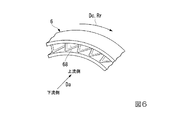
予旋回ノズル67は、図6に示すように、周方向Dcに並ぶ複数の旋回翼68を有する。この旋回翼68は、下流側から上流側に向うに連れて次第にロータ軸32の回転方向Rr側に傾いている。この予旋回ノズル67は、下流側の空気受入空間66内に流入した冷却空気の圧力の一部を、ロータ軸32の回転方向Rrへの運動エネルギーに変換して、冷却空気に回転方向Rrの速度成分を付与するノズルである。
As shown in FIG. 6, the
次に、以上で説明したガスタービンにおける冷却空気の流れについて説明する。 Next, the flow of cooling air in the gas turbine described above will be described.
圧縮機10の中圧抽気ポート16から抽気されて動翼用中圧抽気管85に流れ込んだ冷却空気は、第一実施形態と同様、冷却器86を通過する過程で冷却され、空気調節弁87により流量調節された後、その一部がロータ軸32の軸方向通路45に流入する。軸方向通路45に流入する直前の冷却空気は、図7に示すように、その圧力が8ata程度にまで低下しており、その温度も低下している。
The cooling air extracted from the intermediate
軸方向通路45に流入した冷却空気は、第一実施形態と同様、この軸方向通路45から径方向外側に向かって延びる強制渦通路46を経て、第四キャビティ52d内に流入する。冷却空気は、径方向外側に向かって延びる強制渦通路46を通る過程で、軸線Arを中心として回転するロータ軸32から遠心力を受けて加圧される。この結果、第四キャビティ52d内に至った冷却空気の圧力は9ataになる。なお、第四キャビティ52d内の冷却空気は、加圧により温度が上昇する。
The cooling air that has flowed into the
第四キャビティ52d内の冷却空気は、第四ディスク通路53d、第三キャビティ52c、第三ディスク通路53cを経て、第二キャビティ52b内に流入する。第二キャビティ52b内の冷却空気の圧力は、第四キャビティ52d内の冷却空気の圧力とほぼ同じで9ataであり、この冷却空気の温度は、第四キャビティ52d内の冷却空気の温度とほぼ同じである。
The cooling air in the
第二キャビティ52b内に流入した冷却空気の一部は、第一実施形態と同様、第三段翼列通路48の一部を成す第三段連通路56を経て、第三段動翼列33cを構成する複数の動翼中の冷却空気通路内に流入する。この冷却空気は、第三段連通路56を通る過程で、圧力及び流量が調節され、第三段連通路56から第三段動翼列33cの動翼中に流入する直前には、その圧力がほぼ7ataになる。この冷却空気は、第三段動翼列33cを構成する複数の動翼中の冷却空気通路を通って、動翼を冷却した後、燃焼ガス流路39中に排出される。
A part of the cooling air flowing into the
第二キャビティ52b内に流入した冷却空気の残りの一部は、第一実施形態と同様、第二段翼列通路47の一部を成す第二段連通路55を経て、第二段動翼列33bを構成する複数の動翼中の冷却空気通路内に流入する。この冷却空気は、第二段連通路55を通る過程で、圧力及び流量が調節される。この結果、第二段連通路55から第二段動翼列33bの動翼中に流入する直前の冷却空気は、その圧力がほぼ9ataになる。この冷却空気は、第二段動翼列33bを構成する複数の動翼中の冷却空気通路を通って、動翼を冷却した後、燃焼ガス流路39中に排出される。
The remaining part of the cooling air that has flowed into the
動翼用中圧抽気管85を流れる冷却空気の一部は、抽気分岐管88に流れ込む。抽気分岐管88に流れ込んだ冷却空気は、その圧力が8ata程度である。
A part of the cooling air flowing through the intermediate
冷却空気は、抽気分岐管88から空気受入空間66に流入した後、予旋回ノズル67を経て、大径部端キャビティ65内に流入する。冷却空気は、予旋回ノズル67を通過する過程で、圧力の一部がロータ軸32の回転方向Rrへの運動エネルギーに変換されて、回転方向Rrの速度成分が付与される。予旋回ノズル67を通過した後の冷却空気は、その圧力が5ata程度まで低下する。また、予旋回ノズル67を通過した後の冷却空気の軸線Arを基準にした周速度は、ロータ軸32中の第五キャビティ52eの位置における周速度とほぼ同じになる。すなわち、大径部端キャビティ65内の冷却空気は、ロータ軸32中の第五キャビティ52eとほぼ同じ周速度で、環状の大径部端キャビティ65内を旋回する。このため、大径部端キャビティ65内の冷却空気は、ロータ軸32中の第五キャビティ52e内に流入するにあたり、ロータ軸32の回転を妨げる抵抗にならない。
The cooling air flows from the
第五キャビティ52e内に流入した冷却空気の圧力は、ほぼ5ataである。
The pressure of the cooling air that has flowed into the
第五キャビティ52e内の冷却空気は、第四段翼列通路49aの一部を成す第四段連通路57aを経て、第四段動翼列33dを構成する複数の動翼中の冷却空気通路内に流入する。この冷却空気は、第四段連通路57aを通る過程で、圧力及び流量が調節される。この結果、第四段連通路57aから第四段動翼列33dの動翼中に流入する直前の冷却空気は、その圧力が3ataになる。この冷却空気は、第四段動翼列33dを構成する複数の動翼中の冷却空気通路を通って、動翼を冷却した後、燃焼ガス流路39中に排出される。
The cooling air in the
以上のように、本実施形態でも、第一実施形態と同様、圧縮機10から抽気した空気により、タービン30の動翼を冷却することができる。さらに、本実施形態でも、圧縮機10の駆動力を抑えることができ、ガスタービンの効率の低下を抑えることができる。
As described above, also in this embodiment, the moving blades of the
また、本実施形態でも、第一実施形態と同様に、最下流の動翼列33よりも下流側に形成した強制渦通路46で空気を昇圧した後、これを複数の動翼列33毎に分配しているので、タービンロータ31の振動特性の悪化及びタービン30の空力性能の低下を抑えることができる。
Also in the present embodiment, as in the first embodiment, after the pressure of air is increased by the forced
また、第一実施形態では、第二段動翼列33b及び第三段動翼列33cを冷却する冷却空気の全てを強制渦通路46に流入させ、ここでタービンロータ31の回転により生じる遠心力を利用して冷却空気を昇圧させている。一方、本実施形態では、第二段動翼列33b及び第三段動翼列33cを冷却する冷却空気のみを強制渦通路46に流入させて昇圧させ、第四段動翼列33dを冷却する冷却空気に関しては、強制渦通路46に流入させずに予旋回ノズル67を通過させることで旋回させ、タービンロータ31の回転抵抗を減らしている。よって、本実施形態では、第一実施形態よりもタービンロータ31の回転抵抗が小さくなり、ガスタービンの効率を高めることができる。
In the first embodiment, all the cooling air for cooling the second stage moving
また、本実施形態では、第四段動翼列33d用の冷却空気は、ロータ軸32外に設けられている抽気分岐管88内を通るので、この抽気分岐管88に空気調節弁や冷却器を設けることで、この第四段動翼列33d用の冷却空気の流量、圧力、温度を容易に調節することができる。
In this embodiment, since the cooling air for the fourth stage moving
「第三実施形態」
本発明に係るガスタービンの第三実施形態について、図8〜図10を参照して説明する。
"Third embodiment"
A third embodiment of the gas turbine according to the present invention will be described with reference to FIGS.
第一及び第二実施形態のガスタービンでは、いずれも、圧縮機10の中圧抽気ポート16からの抽気した冷却空気を第二、第三及び第四段動翼列33b,33c,33d用の冷却空気として利用している。
In the gas turbines of the first and second embodiments, the cooling air extracted from the medium-
本実施形態のガスタービンでは、図8及び図10に示すように、圧縮機10の中圧抽気ポート16(第一抽気ポート)からの抽気した冷却空気を第二及び第三段動翼列33b,33c用の冷却空気として利用し、圧縮機10の低圧抽気ポート17(第二抽気ポート)からの抽気した冷却空気を第四段動翼列33d用の冷却空気として利用する。
In the gas turbine of the present embodiment, as shown in FIGS. 8 and 10, the cooling air extracted from the medium pressure extraction port 16 (first extraction port) of the
本実施形態の圧縮機車室15の中間段に対応する位置には、中圧抽気ポート16と低圧抽気ポート17とが形成されている。低圧抽気ポート17は、中圧抽気ポート16が形成されている位置よりも上流側に形成されている。このため、低圧抽気ポート17から抽気される空気の圧力は、中圧抽気ポート16から抽気される空気の圧力よりも低く、例えば、6atmである。
An intermediate
本実施形態の抽気ライン80bは、第一実施形態と同様、中圧抽気管81と、この中圧抽気管81に設けられている冷却器86、空気調節弁87、空気調節器84と、を有する。中圧抽気管81は、第一実施形態と同様に、圧縮機10の中圧抽気ポート16に接続されている中圧抽気本管82と、中圧抽気本管82に接続されている静翼用中圧抽気管83及び動翼用中圧抽気管85と、を有する。静翼用中圧抽気管83には、前述の空気調節器84が設けられ、動翼用中圧抽気管85には、前述の冷却器86及び空気調節弁87が設けられている。
As in the first embodiment, the
本実施形態の抽気ライン80bは、さらに、低圧抽気管91と、この低圧抽気管91に設けられている冷却器96、空気調節弁97、空気調節器94と、を有する。低圧抽気管91は、圧縮機10の低圧抽気ポート17に接続されている低圧抽気本管92と、低圧抽気本管92に接続されている静翼用低圧抽気管93及び動翼用低圧抽気管95と、を有する。
The
静翼用低圧抽気管93は、タービン車室35で、タービン30の中間段に対応する位置に接続されている。より具体的には、タービン車室35で、静翼用中圧抽気管83が接続されている位置よりも下流側に接続されている。この静翼用低圧抽気管93には、ここを通る空気の圧力及び流量を調節するためのオリフィス等の空気調節器94が設けられている。動翼用低圧抽気管95は、ロータ軸32に接続されている。この動翼用低圧抽気管95に、前述の冷却器96及び空気調節弁97が設けられている。冷却器96は、この動翼用低圧抽気管95を通る空気を冷却する。空気調節弁97は、この動翼用低圧抽気管95を通る空気の流量を調節する。この動翼用低圧抽気管95の端部は、軸受カバー71に固定されている。
The stationary blade low-
本実施形態のロータ軸32には、第一及び第二実施形態と同様、中圧抽気ポート16からの冷却空気が流入し、軸方向Daに延びる第一軸方向通路45と、第一軸方向通路45に接続され径方向外側に延びる第一強制渦通路46と、第一強制渦通路46を通過した冷却空気を第二段動翼列33b(第一動翼列)に導く第二段翼列通路47(第一翼列通路)と、第一強制渦通路46を通過した冷却空気を第三段動翼列33c(第二動翼列)に導く第三段翼列通路48(第二翼列通路)と、が形成されている。さらに、本実施形態のロータ軸32には、低圧抽気ポート17からの冷却空気が流入し、軸方向Daに延びる第二軸方向通路45bと、第二軸方向通路45bに接続され径方向外側に延びる第二強制渦通路46bと、第二強制渦通路46bを通過した冷却空気を第四段動翼列33d(第三動翼列)に導く第四段翼列通路49b(第三翼列通路)と、が形成されている。
As in the first and second embodiments, the cooling air from the medium-
ロータ軸32の大径部44には、第一及び第二実施形態のロータ軸32の大径部44と同様、第一キャビティ52a、第二キャビティ52b、第三キャビティ52c、第四キャビティ52dが形成されている。第四キャビティ52dは、第一強制渦通路46の径方向外側の端部と接続されている。第四キャビティ52dと第三キャビティ52cとは、第四ディスク通路53dで接続され、第三キャビティ52cと第二キャビティ52bとは、第三ディスク通路53cで接続されている。第二キャビティ52bと第三段動翼列33cとは、第三段連通路56で接続され、第二キャビティ52bと第二段動翼列33bとは、第二段連通路55で接続されている。
Like the
よって、本実施形態でも、第三段翼列通路48は、第四キャビティ52dと第四ディスク通路53dと第三キャビティ52cと第三ディスク通路53cと第二キャビティ52bと第三段連通路56とで形成されている。また、第二段翼列通路47は、第四キャビティ52dと第四ディスク通路53dと第三キャビティ52cと第三ディスク通路53cと第二キャビティ52bと第二段連通路55とで形成されている。
Therefore, also in this embodiment, the third stage cascade passage 48 includes the
第二軸方向通路45bは、図8及び図9に示すように、軸線Arを中心として軸方向Daに延びている第一軸方向通路45の径方向外側の位置に形成されている。第二軸方向通路45bの下流端には、この下流端から径方向外側に延び、小径部43の外周面で開口する低圧空気受入通路45cが形成されている。
As shown in FIGS. 8 and 9, the second
軸受カバー71中で、軸方向Daで低圧空気受入通路45cの開口と実質的に同じ位置には、外周側から内周側に向かって貫通する貫通孔が形成されている。動翼用低圧抽気管95の端部は、この貫通孔が形成されている位置に固定されている。軸受カバー71の内周側と小径部43の外周側との間であって、軸受カバー71の貫通孔を基準にして上流側及び下流側のそれぞれはシール部材72b,72cでシールされている。
A through hole penetrating from the outer peripheral side toward the inner peripheral side is formed in the bearing cover 71 at substantially the same position as the opening of the low-pressure
大径部44の下流側であって径方向外側は、大径部端カバー62bで覆われている。この大径部端カバー62bと大径部44との間には、軸線Arを中心として環状の第五キャビティ52fが形成されている。
The downstream side of the large-
第二軸方向通路45bの上流端には、この上流端から径方向外側に延び、第五キャビティ52fに連通する第二強制渦通路46bが接続されている。この第二強制渦通路46bは、大径部44中で第一強制渦通路46よりも下流側の位置に形成されている。大径部44には、第五キャビティ52fと第四段動翼列33dの取付位置とを連通させる第四段連通路57bが形成されている。
A second forced
よって、本実施形態の第四段翼列通路49bは、第五キャビティ52fと第四段連通路57bとで形成されている。
Therefore, the fourth
次に、以上で説明したガスタービンにおける冷却空気の流れについて説明する。 Next, the flow of cooling air in the gas turbine described above will be described.
圧縮機10の中圧抽気ポート16から抽気されて動翼用中圧抽気管85に流れ込んだ冷却空気は、第一及び第二実施形態と同様、冷却器86を通過する過程で冷却され、空気調節弁87により流量調節された後、ロータ軸32の第一軸方向通路45に流入する。第一軸方向通路45に流入する直前の冷却空気は、図10に示すように、その圧力が8ata程度にまで低下しており、その温度も低下している。
The cooling air extracted from the medium
第一軸方向通路45に流入した冷却空気は、第一及び第二実施形態と同様、この第一軸方向通路45から径方向外側に向かって延びる第一強制渦通路46を経て、第四キャビティ52d内に流入する。冷却空気は、径方向外側に向かって延びる強制渦通路46を通る過程で、軸線Arを中心として回転するロータ軸32から遠心力を受けて加圧される。この結果、第四キャビティ52d内に至った冷却空気の圧力は9ataになる。なお、第四キャビティ52d内の冷却空気は、加圧により温度が上昇する。
The cooling air that has flowed into the first
第四キャビティ52d内の冷却空気は、第四ディスク通路53d、第三キャビティ52c、第三ディスク通路53cを経て、第二キャビティ52b内に流入する。第二キャビティ52b内の冷却空気の圧力は、第四キャビティ52d内の冷却空気の圧力とほぼ同じで9ataであり、この冷却空気の温度は、第四キャビティ52d内の冷却空気の温度とほぼ同じである。
The cooling air in the
第二キャビティ52b内に流入した冷却空気の一部は、第一及び第二実施形態と同様、第三段翼列通路48の一部を成す第三段連通路56を経て、第三段動翼列33cを構成する複数の動翼中の冷却空気通路内に流入する。この冷却空気は、第三段連通路56を通る過程で、圧力及び流量が調節される。この結果、第三段連通路56から第三段動翼列33cの動翼中に流入する直前の冷却空気は、その圧力がほぼ7ataになる。この冷却空気は、第三段動翼列33cを構成する複数の動翼中の冷却空気通路を通って、動翼を冷却した後、燃焼ガス流路39中に排出される。
A part of the cooling air flowing into the
第二キャビティ52b内に流入した冷却空気の残りの一部は、第一実施形態と同様、第二段翼列通路47の一部を成す第二段連通路55を経て、第二段動翼列33bを構成する複数の動翼中の冷却空気通路内に流入する。この冷却空気は、第二段連通路55を通る過程で、圧力及び流量が調節される。この結果、第二段連通路55から第二段動翼列33bの動翼中に流入する直前の冷却空気は、その圧力がほぼ9ataになる。この冷却空気は、第二段動翼列33bを構成する複数の動翼中の冷却空気通路を通って、動翼を冷却した後、燃焼ガス流路39中に排出される。
The remaining part of the cooling air that has flowed into the
圧縮機10の低圧抽気ポート17から抽気された冷却空気は、抽気ライン80bの低圧抽気本管92を流れ、その一部が静翼用低圧抽気管93に流れ込み、残りの一部が動翼用低圧抽気管95に流れ込む。静翼用低圧抽気管93に流れ込んだ冷却空気は、空気調節器94を通る過程で、その圧力が4ataになって、第四段静翼列34dを構成する複数の静翼に供給され、これら複数の静翼を冷却する。
The cooling air extracted from the low-
動翼用低圧抽気管95に流れ込んだ冷却空気は、冷却器96を通過する過程で冷却され、空気調節弁97により流量調節された後、ロータ軸32の第二軸方向通路45bに流入する。第二軸方向通路45bに流入する直前の冷却空気は、冷却器96や空気調節弁97を通過する過程等での圧力損失により、その圧力が4ata程度にまで低下している。また、第二軸方向通路45bに流入する直前の冷却空気は、冷却器86により冷却される。
The cooling air that has flowed into the moving blade low-
第二軸方向通路45bに流入した冷却空気は、この第二軸方向通路45bから径方向外側に向かって延びる第二強制渦通路46bを経て、第五キャビティ52f内に流入する。冷却空気は、径方向外側に向かって延びる第二強制渦通路46bを通る過程で、軸線Arを中心として回転するロータ軸32から遠心力を受けて加圧される。この結果、第五キャビティ52f内に至った冷却空気の圧力は5ataになる。
The cooling air flowing into the second
第五キャビティ52f内の冷却空気は、第四段翼列通路49bの一部を成す第四段連通路57bを経て、第四段動翼列33dを構成する複数の動翼中の冷却空気通路内に流入する。この冷却空気は、第四段連通路57bを通る過程で、圧力及び流量が調節される。また、この冷却空気は、燃焼ガス流路39に近づくに連れて、燃焼ガスの熱との熱交換量が増えて、その温度が徐々に高まる。この結果、第四段連通路57bから第四段動翼列33dの動翼中に流入する直前の冷却空気は、その圧力が3ataになる。この冷却空気は、第四段動翼列33dを構成する複数の動翼中の冷却空気通路を通って、動翼を冷却した後、燃焼ガス流路39中に排出される。
The cooling air in the
以上のように、本実施形態でも、第一及び第二実施形態と同様、圧縮機10から抽気した空気により、タービン30の動翼を冷却することができる。さらに、本実施形態でも、圧縮機10での駆動力を抑えることができ、ガスタービンの効率の低下を抑えることができる。
As described above, also in this embodiment, the moving blades of the
また、本実施形態では、第一及び第二強制渦通路46,46bを最下流の動翼列33よりも下流側に形成している上に、第一強制渦通路46で空気を昇圧した後、これを第二段動翼列33b及び第三段動翼列33cに分配している。このため、本実施形態でも、ロータ軸32の長さ及び段間距離の伸長化が抑えられ、ロータの振動特性の悪化及びタービン30の空力性能の低下を抑えることができる。
In the present embodiment, the first and second forced
本実施形態において、第四段動翼列33dには、第二段動翼列33bや第三段動翼列33cに供給する冷却空気の圧力よりも低い圧力の冷却空気でも供給することができる。しかも、本実施形態では、圧縮機10から抽気した空気を回転するロータ軸32に流入させ、このロータ軸32中で冷却空気の強制渦を発生させることで、冷却空気の圧力を高めてから、第四段動翼列33dに空気供給している。このため、本実施形態では、中圧抽気ポート16からの空気よりも低圧の空気を低圧抽気ポート17から冷却空気として抽気し、これを第四段動翼列33dの冷却空気として利用することができる。よって、本実施形態では、圧縮機10で第四段動翼列33dの冷却用の空気の圧縮比を小さくできる結果、圧縮機10の駆動力を抑えることができる。よって、本実施形態では、第一実施形態よりもガスタービンの効率を高めることができる。
In the present embodiment, the fourth stage moving
「第三実施形態の変形例」
第三実施形態の変形例について、図11を参照して説明する。
"Modification of the third embodiment"
A modification of the third embodiment will be described with reference to FIG.
第三実施形態では、第一強制渦通路46の径方向外側の端部が第四キャビティ52dに接続されている。第四キャビティ52dは、第四ディスク通路53d、第三キャビティ52c及び第三ディスク通路53cを介して、第二キャビティ52bと接続されている。この第二キャビティ52bは、第二段連通路55を介して、第二段動翼列33bに接続されていると共に、第三段連通路56を介して、第三段動翼列33cに接続されている。
In the third embodiment, the radially outer end of the first forced
本変形例では、スピンドルボルト41が挿通されるロータ軸32のボルト孔41cの断面形状を長円形状にし、スピンドルボルト41が挿通されたボルト孔41c中の隙間を冷却空気の通路53eとしている。この通路53eは、スピンドルボルト41と同様に、軸方向Daに延びている。この通路53eの下流端には、第一強制渦通路46の径方向外側端部が接続されている。また、この通路53eの上流端には、第二キャビティ52bが接続されている。この第二キャビティ52bは、以上の各実施形態と同様、第二段連通路55を介して、第二段動翼列33bに接続されていると共に、第三段連通路56を介して、第三段動翼列33cに接続されている。
In this modification, the cross-sectional shape of the bolt hole 41c of the
また、本変形例では、第二強制渦通路46bの径方向外側の端部に第四キャビティ52dが接続されている。この第四キャビティ52dは、第四段連通路57を介して、第四段動翼列33dと接続されている。
In the present modification, the
以上のように、強制渦通路と各動翼列とを接続する通路は、タービンロータの構造に応じて、適宜形成してよい。 As described above, the passage connecting the forced vortex passage and each rotor blade row may be appropriately formed according to the structure of the turbine rotor.
「その他の変形例」
第一、第二及び第三実施形態の動翼用中圧抽気管85や、第三実施形態の動翼用低圧抽気管95には、空気調節弁87,97や冷却器86,96を設けているが、これらは必須のものではない。よって、これらの抽気管における空気調節弁87,97や冷却器86,96を適宜省略してもよい。
"Other variations"
Air
また、以上の実施形態では、複数の動翼列33への冷却空気が通る強制渦通路46を最下流の動翼列33よりも下流側に配置している。しかしながら、ロータ軸32の大径部44におけるいずれかの段間に強制渦通路46を形成してもよい。この場合においても、強制渦通路46の径方向外側の端で、この通路46を複数の動翼列33毎に分岐させることで、強制渦通路46の数を少なくでき、結果として、ロータ軸32の長さの伸長化、複数段の段間距離の伸張化を抑えることができる。但し、強制渦通路46は、全ての段間距離の伸張化を抑える観点から、以上の実施形態のように、最下流の動翼列33よりも下流側に形成することが好ましい。
Further, in the above embodiment, the forced
また、以上の実施形態では、いずれも、圧縮機車室15に抽気ポート16,17を形成し、圧縮機車室15外及びタービン車室35外に抽気ライン80を配置している。しかしながら、例えば、圧縮機ロータ11に抽気ポートを形成し、この抽気ポートに圧縮機ロータ11及びタービンロータ31内を軸方向Daに延びる軸方向通路を接続してもよい。
In each of the above embodiments, the
1:ガスタービンロータ、5:ガスタービン車室、10:圧縮機、11:圧縮機ロータ、12:ロータ軸、13:動翼列、14:静翼列、15:圧縮機車室、16:中圧抽気ポート(第一抽気ポート)、17:低圧抽気ポート(第二抽気ポート)、19:空気圧縮流路、20:燃焼器、30:タービン、31:タービンロータ、32:ロータ軸、33:動翼列、33a:第一段動翼列、33b:第二段動翼列(第一動翼列)、33c:第三段段動翼列(第二動翼列)、33d:第四段動翼列(第三動翼列)、34:静翼列、35:タービン車室、39:燃焼ガス流路、43:小径部、44:大径部、45:軸方向通路(第一軸方向通路)、45b:第二軸方向通路、46:強制渦通路(第一強制渦通路)、46b:第二強制渦通路、47:第二段翼列通路(第一翼列通路)、48:第三段翼列通路(第二翼列通路)、49,49a,49b:第四段翼列通路(第三翼列通路)、52a:第一キャビティ、52b:第二キャビティ、52c:第三キャビティ、52d:第四キャビティ、52e,52f:第五キャビティ、65:大径部端キャビティ、66:空気受入空間、67:予旋回ノズル、70:軸受、71:軸受カバー、80,80b:抽気ライン、81:中圧抽気管、88:抽気分岐管、91:低圧抽気管 1: gas turbine rotor, 5: gas turbine casing, 10: compressor, 11: compressor rotor, 12: rotor shaft, 13: moving blade row, 14: stationary blade row, 15: compressor casing, 16: middle Pressure extraction port (first extraction port), 17: Low pressure extraction port (second extraction port), 19: Air compression flow path, 20: Combustor, 30: Turbine, 31: Turbine rotor, 32: Rotor shaft, 33: Rotor blade row, 33a: first stage blade row, 33b: second stage blade row (first blade row), 33c: third stage blade row (second blade row), 33d: fourth row Moving blade row (third moving blade row), 34: stationary blade row, 35: turbine casing, 39: combustion gas flow path, 43: small diameter portion, 44: large diameter portion, 45: axial passage (first shaft) Direction passage), 45b: second axial passage, 46: forced vortex passage (first forced vortex passage), 46b: second forced vortex passage, 47: second stage blade row passage (first blade row) ), 48: third stage cascade path (second cascade path), 49, 49a, 49b: fourth stage cascade path (third cascade path), 52a: first cavity, 52b: second cavity 52c: third cavity, 52d: fourth cavity, 52e, 52f: fifth cavity, 65: large diameter end cavity, 66: air receiving space, 67: pre-swivel nozzle, 70: bearing, 71: bearing cover, 80, 80b: extraction line, 81: medium pressure extraction pipe, 88: extraction branch pipe, 91: low pressure extraction pipe
Claims (7)
前記圧縮機で圧縮された空気中で燃料を燃焼させて燃焼ガスを生成する燃焼器と、
前記燃焼ガスにより駆動するタービンと、
中圧抽気管と、
を備え、
前記圧縮機は、前記圧縮機の中間段から空気を冷却空気として抽気する抽気ポートを有し、
前記タービンは、ロータ軸と、前記ロータ軸の外周に取り付けられた複数の動翼を備えて前記ロータ軸の軸方向に並ぶ複数の動翼列と、複数の前記動翼列毎の軸方向上流側に配置されている複数の静翼列と、を有し、
前記中圧抽気管は、前記抽気ポートに接続されている中圧抽気本管と、前記中圧抽気本管に接続されている静翼用中圧抽気管及び動翼用中圧抽気管と、を有し、
前記ロータ軸には、
前記動翼用中圧抽気管に連通し、前記軸方向に延びる軸方向通路と、
前記軸方向通路に接続され、前記軸方向通路との接続部から前記ロータ軸の径方向外側に延びる強制渦通路と、
前記強制渦通路における径方向外側の端部に接続され、複数の前記動翼列のうちの第一動翼列に前記冷却空気を導く第一翼列通路と、
前記強制渦通路における径方向外側の端部に接続され、複数の前記動翼列のうちの第二動翼列に前記冷却空気を導く第二翼列通路と、
が形成され、
複数の前記静翼列のうち、前記軸方向における前記第一動翼列と前記第二動翼列との間の静翼列には、前記静翼用中圧抽気管が接続されている、
ガスタービン。 A compressor for compressing air;
A combustor that generates a combustion gas by burning fuel in air compressed by the compressor;
A turbine driven by the combustion gas;
Medium pressure bleed pipe,
With
The compressor has an extraction port for extracting air as cooling air from an intermediate stage of the compressor,
The turbine includes a rotor shaft, a plurality of blades attached to an outer periphery of the rotor shaft, and a plurality of blade rows arranged in the axial direction of the rotor shaft, and an upstream in the axial direction for each of the plurality of blade rows A plurality of stationary blade rows arranged on the side ,
The intermediate pressure extraction pipe includes an intermediate pressure extraction main pipe connected to the extraction port, an intermediate pressure extraction pipe for stationary blades and an intermediate pressure extraction pipe for moving blades connected to the intermediate pressure extraction main pipe, Have
In the rotor shaft,
An axial passage communicating with the intermediate pressure extraction pipe for the moving blade and extending in the axial direction;
A forced vortex passage connected to the axial passage and extending radially outward of the rotor shaft from a connecting portion with the axial passage;
A first blade row passage connected to a radially outer end of the forced vortex passage and guiding the cooling air to a first blade row of the plurality of blade rows;
A second blade row passage connected to a radially outer end of the forced vortex passage and guiding the cooling air to a second blade row of the plurality of blade rows;
Formed,
Among the plurality of stationary blade rows, the stationary blade intermediate pressure bleed pipe is connected to the stationary blade row between the first moving blade row and the second moving blade row in the axial direction.
gas turbine.
前記強制渦通路は、複数の前記動翼列のうちで、前記軸方向における燃焼ガスの流れの最も下流側に配置されている第三動翼列の下流側に形成されている、
ガスタービン。 The gas turbine according to claim 1, wherein
The forced vortex passage is formed on the downstream side of the third rotor blade row arranged on the most downstream side of the flow of combustion gas in the axial direction among the plurality of rotor blade rows.
gas turbine.
前記第二翼列通路を通る前記冷却空気の圧力を調節する手段を有する、
ガスタービン。 The gas turbine according to claim 1, wherein
Means for adjusting the pressure of the cooling air through the second cascade passage;
gas turbine.
前記ロータ軸には、前記強制渦通路における径方向外側の端部に接続され、複数の前記動翼列のうちで、前記軸方向における燃焼ガスの流れの最も下流側に配置されている第三動翼列に前記冷却空気を導く第三翼列通路が形成されている、
ガスタービン。 The gas turbine according to any one of claims 1 to 3 ,
The rotor shaft is connected to the radially outer end of the forced vortex passage, and is arranged at the most downstream side of the flow of combustion gas in the axial direction among the plurality of rotor blade rows. A third blade row passage for guiding the cooling air to the blade row is formed;
gas turbine.
前記第三翼列通路を通る前記冷却空気の圧力を調節する手段を有する、
ガスタービン。 The gas turbine according to claim 4 , wherein
Means for adjusting the pressure of the cooling air through the third cascade passage;
gas turbine.
前記圧縮機で圧縮された空気中で燃料を燃焼させて燃焼ガスを生成する燃焼器と、
前記燃焼ガスにより駆動するタービンと、
を備え、
前記圧縮機は、前記圧縮機の中間段から空気を冷却空気として抽気する抽気ポートを有し、
前記タービンは、ロータ軸と、前記ロータ軸の外周に取り付けられた複数の動翼を備えて前記ロータ軸の軸方向に並ぶ複数の動翼列と、を有し、
前記ロータ軸には、
前記抽気ポートに接続され、前記軸方向に延びる軸方向通路と、
前記軸方向通路に接続され、前記軸方向通路との接続部から前記ロータ軸の径方向外側に延びる強制渦通路と、
前記強制渦通路における径方向外側の端部に接続され、複数の前記動翼列のうちの第一動翼列に前記冷却空気を導く第一翼列通路と、
前記強制渦通路における径方向外側の端部に接続され、複数の前記動翼列のうちの第二動翼列に前記冷却空気を導く第二翼列通路と、
が形成され、
さらに、
前記抽気ポートと前記軸方向通路とを接続する抽気管と、
前記抽気管に接続された抽気分岐管と、
前記抽気分岐管に接続され、前記抽気分岐管を流れてきた前記冷却空気に前記ロータ軸の回転方向の速度成分を付与する予旋回ノズルと、
を備え、
前記ロータ軸には、複数の前記動翼列のうちで、前記軸方向における燃焼ガスの流れの最も下流側に配置されている第三動翼列に前記予旋回ノズルを通過した前記冷却空気を導く第三翼列通路が形成されている、
ガスタービン。 A compressor for compressing air;
A combustor that generates a combustion gas by burning fuel in air compressed by the compressor;
A turbine driven by the combustion gas;
With
The compressor has an extraction port for extracting air as cooling air from an intermediate stage of the compressor,
The turbine has a rotor shaft, and a plurality of blade rows arranged in the axial direction of the rotor shaft, including a plurality of blades attached to the outer periphery of the rotor shaft,
In the rotor shaft,
An axial passage connected to the bleed port and extending in the axial direction;
A forced vortex passage connected to the axial passage and extending radially outward of the rotor shaft from a connecting portion with the axial passage;
A first blade row passage connected to a radially outer end of the forced vortex passage and guiding the cooling air to a first blade row of the plurality of blade rows;
A second blade row passage connected to a radially outer end of the forced vortex passage and guiding the cooling air to a second blade row of the plurality of blade rows;
Formed,
further,
A bleed pipe connecting the bleed port and the axial passage;
An extraction branch pipe connected to the extraction pipe;
A pre-swirl nozzle that is connected to the extraction branch pipe and applies a speed component in the rotation direction of the rotor shaft to the cooling air that has flowed through the extraction branch pipe;
With
The rotor shaft is provided with the cooling air that has passed through the pre-swirl nozzle in a third blade row that is arranged on the most downstream side of the flow of combustion gas in the axial direction among the plurality of blade rows. A third blade row passage is formed,
gas turbine.
前記圧縮機で圧縮された空気中で燃料を燃焼させて燃焼ガスを生成する燃焼器と、
前記燃焼ガスにより駆動するタービンと、
を備え、
前記圧縮機は、前記圧縮機の中間段から空気を冷却空気として抽気する第一抽気ポートと、前記第一抽気ポートよりも、前記圧縮機内の前記空気の流れの上流側における中間段から空気を冷却空気として抽気する第二抽気ポートと、を有し、
前記タービンは、ロータ軸と、前記ロータ軸の外周に取り付けられた複数の動翼を備えて前記ロータ軸の軸方向に並ぶ複数の動翼列と、を有し、
前記ロータ軸には、
前記第一抽気ポートに接続され、前記軸方向に延びる第一軸方向通路と、
前記第一軸方向通路に接続され、前記第一軸方向通路との接続部から前記ロータ軸の径方向外側に延びる第一強制渦通路と、
前記第一強制渦通路における径方向外側の端部に接続され、複数の前記動翼列のうちの第一動翼列に前記冷却空気を導く第一翼列通路と、
前記第一強制渦通路における径方向外側の端部に接続され、複数の前記動翼列のうちの第二動翼列に前記冷却空気を導く第二翼列通路と、
前記第二抽気ポートに接続され、前記第一軸方向通路よりも径方向外側で、前記軸方向に延びる第二軸方向通路と、
前記第二軸方向通路に接続され、複数の前記動翼列のうちで、前記軸方向における燃焼ガスの流れの最も下流側に配置されている第三動翼列よりも下流側で、前記第二軸方向通路との接続部から径方向外側に延びる第二強制渦通路と、
前記第二強制渦通路における径方向外側の端部に接続され、前記第三動翼列に前記冷却空気を導く第三翼列通路と、
が形成されている、
ガスタービン。 A compressor for compressing air;
A combustor that generates a combustion gas by burning fuel in air compressed by the compressor;
A turbine driven by the combustion gas;
With
The compressor includes a first extraction port for extracting air as cooling air from an intermediate stage of the compressor, and air from an intermediate stage upstream of the air flow in the compressor from the first extraction port. A second bleed port for bleed as cooling air ,
The turbine has a rotor shaft, and a plurality of blade rows arranged in the axial direction of the rotor shaft, including a plurality of blades attached to the outer periphery of the rotor shaft,
In the rotor shaft,
A first axial passage connected to the first bleed port and extending in the axial direction;
A first forced vortex passage connected to the first axial passage and extending radially outward of the rotor shaft from a connecting portion with the first axial passage;
A first blade row passage that is connected to a radially outer end of the first forced vortex passage and guides the cooling air to the first blade row of the plurality of blade rows;
A second blade row passage that is connected to a radially outer end of the first forced vortex passage and guides the cooling air to a second blade row of the plurality of blade rows;
Is connected to the second bleed port, radially outward from the front Symbol first axial direction passage, a second axial passage extending in the axial direction,
Of the plurality of moving blade rows connected to the second axial passage, the first moving blade row arranged downstream of the third moving blade row disposed on the most downstream side of the combustion gas flow in the axial direction, A second forced vortex passage extending radially outward from the connection with the biaxial passage;
A third blade row passage connected to the radially outer end of the second forced vortex passage and guiding the cooling air to the third blade row;
Is formed,
gas turbine.
Priority Applications (6)
| Application Number | Priority Date | Filing Date | Title |
|---|---|---|---|
| JP2014175185A JP6432110B2 (en) | 2014-08-29 | 2014-08-29 | gas turbine |
| US15/502,311 US11248466B2 (en) | 2014-08-29 | 2015-07-28 | Gas turbine |
| PCT/JP2015/071418 WO2016031475A1 (en) | 2014-08-29 | 2015-07-28 | Gas turbine |
| KR1020177003831A KR101965986B1 (en) | 2014-08-29 | 2015-07-28 | Gas turbine |
| DE112015003934.1T DE112015003934T5 (en) | 2014-08-29 | 2015-07-28 | gas turbine |
| CN201580042179.XA CN106574556B (en) | 2014-08-29 | 2015-07-28 | Gas turbine |
Applications Claiming Priority (1)
| Application Number | Priority Date | Filing Date | Title |
|---|---|---|---|
| JP2014175185A JP6432110B2 (en) | 2014-08-29 | 2014-08-29 | gas turbine |
Publications (3)
| Publication Number | Publication Date |
|---|---|
| JP2016050494A JP2016050494A (en) | 2016-04-11 |
| JP2016050494A5 JP2016050494A5 (en) | 2017-08-17 |
| JP6432110B2 true JP6432110B2 (en) | 2018-12-05 |
Family
ID=55399376
Family Applications (1)
| Application Number | Title | Priority Date | Filing Date |
|---|---|---|---|
| JP2014175185A Active JP6432110B2 (en) | 2014-08-29 | 2014-08-29 | gas turbine |
Country Status (6)
| Country | Link |
|---|---|
| US (1) | US11248466B2 (en) |
| JP (1) | JP6432110B2 (en) |
| KR (1) | KR101965986B1 (en) |
| CN (1) | CN106574556B (en) |
| DE (1) | DE112015003934T5 (en) |
| WO (1) | WO2016031475A1 (en) |
Families Citing this family (10)
| Publication number | Priority date | Publication date | Assignee | Title |
|---|---|---|---|---|
| US10196928B2 (en) * | 2016-03-02 | 2019-02-05 | General Electric Company | Method and system for piping failure detection in a gas turbine bleeding air system |
| FR3055355B1 (en) * | 2016-08-30 | 2020-06-19 | Safran Aircraft Engines | DEVICE AND METHOD FOR ADJUSTING GAMES BETWEEN A ROTOR AND A CONCENTRIC STATOR OF A TURBOMACHINE |
| EP3342979B1 (en) * | 2016-12-30 | 2020-06-17 | Ansaldo Energia Switzerland AG | Gas turbine comprising cooled rotor disks |
| KR101965506B1 (en) * | 2017-10-17 | 2019-04-03 | 두산중공업 주식회사 | Turbine rotor, turbine and gas turbine comprising the same |
| JP6651665B1 (en) * | 2019-03-28 | 2020-02-19 | 三菱日立パワーシステムズ株式会社 | Turbine casing, gas turbine, and method for preventing deformation of turbine casing |
| JP7271408B2 (en) | 2019-12-10 | 2023-05-11 | 東芝エネルギーシステムズ株式会社 | turbine rotor |
| JP7368260B2 (en) | 2020-01-31 | 2023-10-24 | 三菱重工業株式会社 | turbine |
| JP7414580B2 (en) * | 2020-02-26 | 2024-01-16 | 東芝エネルギーシステムズ株式会社 | turbine |
| US11578621B2 (en) * | 2020-04-08 | 2023-02-14 | General Electric Company | System for cooling turbine shaft coupling |
| JP7463203B2 (en) * | 2020-06-22 | 2024-04-08 | 東芝エネルギーシステムズ株式会社 | Turbine rotor and axial flow turbine |
Family Cites Families (22)
| Publication number | Priority date | Publication date | Assignee | Title |
|---|---|---|---|---|
| US3034298A (en) * | 1958-06-12 | 1962-05-15 | Gen Motors Corp | Turbine cooling system |
| US3043561A (en) * | 1958-12-29 | 1962-07-10 | Gen Electric | Turbine rotor ventilation system |
| US3452542A (en) * | 1966-09-30 | 1969-07-01 | Gen Electric | Gas turbine engine cooling system |
| US4462204A (en) * | 1982-07-23 | 1984-07-31 | General Electric Company | Gas turbine engine cooling airflow modulator |
| US4982564A (en) * | 1988-12-14 | 1991-01-08 | General Electric Company | Turbine engine with air and steam cooling |
| US5144794A (en) * | 1989-08-25 | 1992-09-08 | Hitachi, Ltd. | Gas turbine engine with cooling of turbine blades |
| US5593274A (en) * | 1995-03-31 | 1997-01-14 | General Electric Co. | Closed or open circuit cooling of turbine rotor components |
| US6393829B2 (en) | 1996-11-29 | 2002-05-28 | Hitachi, Ltd. | Coolant recovery type gas turbine |
| JPH10266802A (en) * | 1997-03-21 | 1998-10-06 | Toshiba Corp | Gas turbine rotor |
| JP3567065B2 (en) * | 1997-07-31 | 2004-09-15 | 株式会社東芝 | gas turbine |
| JP3486328B2 (en) * | 1997-09-08 | 2004-01-13 | 三菱重工業株式会社 | Recovery steam-cooled gas turbine |
| US6185924B1 (en) * | 1997-10-17 | 2001-02-13 | Hitachi, Ltd. | Gas turbine with turbine blade cooling |
| US6065282A (en) | 1997-10-29 | 2000-05-23 | Mitsubishi Heavy Industries, Ltd. | System for cooling blades in a gas turbine |
| CA2262050C (en) * | 1998-02-17 | 2003-07-08 | Mitsubishi Heavy Industries, Ltd. | Steam-cooling type gas turbine |
| JP2001123851A (en) * | 1999-10-27 | 2001-05-08 | Mitsubishi Heavy Ind Ltd | Gas turbine |
| JP3481596B2 (en) * | 2001-02-14 | 2003-12-22 | 株式会社日立製作所 | gas turbine |
| US7017349B2 (en) * | 2003-02-05 | 2006-03-28 | Mitsubishi Heavy Industries, Ltd. | Gas turbine and bleeding method thereof |
| US8668437B1 (en) | 2006-09-22 | 2014-03-11 | Siemens Energy, Inc. | Turbine engine cooling fluid feed system |
| JP5129633B2 (en) | 2008-03-28 | 2013-01-30 | 三菱重工業株式会社 | Cover for cooling passage, method for manufacturing the cover, and gas turbine |
| US8277170B2 (en) | 2008-05-16 | 2012-10-02 | General Electric Company | Cooling circuit for use in turbine bucket cooling |
| US8079803B2 (en) * | 2008-06-30 | 2011-12-20 | Mitsubishi Heavy Industries, Ltd. | Gas turbine and cooling air supply structure thereof |
| US8079802B2 (en) | 2008-06-30 | 2011-12-20 | Mitsubishi Heavy Industries, Ltd. | Gas turbine |
-
2014
- 2014-08-29 JP JP2014175185A patent/JP6432110B2/en active Active
-
2015
- 2015-07-28 US US15/502,311 patent/US11248466B2/en active Active
- 2015-07-28 DE DE112015003934.1T patent/DE112015003934T5/en active Pending
- 2015-07-28 CN CN201580042179.XA patent/CN106574556B/en active Active
- 2015-07-28 KR KR1020177003831A patent/KR101965986B1/en active IP Right Grant
- 2015-07-28 WO PCT/JP2015/071418 patent/WO2016031475A1/en active Application Filing
Also Published As
| Publication number | Publication date |
|---|---|
| DE112015003934T5 (en) | 2017-05-11 |
| CN106574556B (en) | 2019-03-29 |
| KR20170031196A (en) | 2017-03-20 |
| US11248466B2 (en) | 2022-02-15 |
| JP2016050494A (en) | 2016-04-11 |
| US20170234135A1 (en) | 2017-08-17 |
| CN106574556A (en) | 2017-04-19 |
| KR101965986B1 (en) | 2019-04-04 |
| WO2016031475A1 (en) | 2016-03-03 |
Similar Documents
| Publication | Publication Date | Title |
|---|---|---|
| JP6432110B2 (en) | gas turbine | |
| US7513740B1 (en) | Turbine ring | |
| US20170248155A1 (en) | Centrifugal compressor diffuser passage boundary layer control | |
| CN107448300A (en) | Airfoil for turbogenerator | |
| US8197209B2 (en) | Systems and methods involving variable throat area vanes | |
| US9103281B2 (en) | Gas turbine engine havinga rotatable off-take passage in a compressor section | |
| EP3081765B1 (en) | Engine bypass valve | |
| CN107435561A (en) | System for the sealing guide rail of the sophisticated integral shroud of cooling turbine bucket | |
| JP2016050494A5 (en) | ||
| JP5496469B2 (en) | Method and system for adjusting cooling fluid in real time in a turbomachine | |
| US20170298742A1 (en) | Turbine engine airfoil bleed pumping | |
| US9903382B2 (en) | Axial compressor for fluid-flow machines | |
| JP5507340B2 (en) | Turbomachine compressor wheel member | |
| EP3196422B1 (en) | Exhaust frame | |
| EP3159486A1 (en) | Wheel space purge flow mixing chamber | |
| US20140271173A1 (en) | Centrifugal compressor with axial impeller exit | |
| JP5700999B2 (en) | Centrifugal compressor | |
| JP5216802B2 (en) | Cooling air supply structure for two-shaft gas turbine | |
| JP2005009410A (en) | Gas turbine and rotor seal air introducing method | |
| RU2226609C2 (en) | Turbine of gas-turbine engine | |
| US10760427B2 (en) | Secondary flow control | |
| US11274555B2 (en) | Turbine rotor | |
| RU2256801C2 (en) | Gas-turbine engine | |
| EP3184749A1 (en) | Wheel space purge flow mixing chamber | |
| JP7463203B2 (en) | Turbine rotor and axial flow turbine |
Legal Events
| Date | Code | Title | Description |
|---|---|---|---|
| A521 | Written amendment |
Free format text: JAPANESE INTERMEDIATE CODE: A523 Effective date: 20170706 |
|
| A621 | Written request for application examination |
Free format text: JAPANESE INTERMEDIATE CODE: A621 Effective date: 20170706 |
|
| A521 | Written amendment |
Free format text: JAPANESE INTERMEDIATE CODE: A821 Effective date: 20170707 |
|
| A131 | Notification of reasons for refusal |
Free format text: JAPANESE INTERMEDIATE CODE: A131 Effective date: 20180612 |
|
| A521 | Written amendment |
Free format text: JAPANESE INTERMEDIATE CODE: A523 Effective date: 20180725 |
|
| A521 | Written amendment |
Free format text: JAPANESE INTERMEDIATE CODE: A821 Effective date: 20180726 |
|
| TRDD | Decision of grant or rejection written | ||
| A01 | Written decision to grant a patent or to grant a registration (utility model) |
Free format text: JAPANESE INTERMEDIATE CODE: A01 Effective date: 20181009 |
|
| A61 | First payment of annual fees (during grant procedure) |
Free format text: JAPANESE INTERMEDIATE CODE: A61 Effective date: 20181019 |
|
| R150 | Certificate of patent or registration of utility model |
Ref document number: 6432110 Country of ref document: JP Free format text: JAPANESE INTERMEDIATE CODE: R150 |
|
| S533 | Written request for registration of change of name |
Free format text: JAPANESE INTERMEDIATE CODE: R313533 |
|
| R350 | Written notification of registration of transfer |
Free format text: JAPANESE INTERMEDIATE CODE: R350 |