JP6428223B2 - Radiation imaging equipment - Google Patents
Radiation imaging equipment Download PDFInfo
- Publication number
- JP6428223B2 JP6428223B2 JP2014249514A JP2014249514A JP6428223B2 JP 6428223 B2 JP6428223 B2 JP 6428223B2 JP 2014249514 A JP2014249514 A JP 2014249514A JP 2014249514 A JP2014249514 A JP 2014249514A JP 6428223 B2 JP6428223 B2 JP 6428223B2
- Authority
- JP
- Japan
- Prior art keywords
- housing
- protective cover
- cover
- casing
- radiographic imaging
- Prior art date
- Legal status (The legal status is an assumption and is not a legal conclusion. Google has not performed a legal analysis and makes no representation as to the accuracy of the status listed.)
- Active
Links
- 238000003384 imaging method Methods 0.000 title claims description 97
- 230000005855 radiation Effects 0.000 title claims description 63
- 230000001681 protective effect Effects 0.000 claims description 170
- 238000009423 ventilation Methods 0.000 claims description 43
- 239000007788 liquid Substances 0.000 claims description 37
- 238000012856 packing Methods 0.000 claims description 27
- 238000001514 detection method Methods 0.000 claims description 15
- 239000000758 substrate Substances 0.000 description 35
- 230000002093 peripheral effect Effects 0.000 description 18
- 210000002700 urine Anatomy 0.000 description 12
- 229920005989 resin Polymers 0.000 description 10
- 239000011347 resin Substances 0.000 description 10
- 229910052751 metal Inorganic materials 0.000 description 9
- 239000002184 metal Substances 0.000 description 9
- 239000000047 product Substances 0.000 description 9
- 238000002474 experimental method Methods 0.000 description 6
- 239000000463 material Substances 0.000 description 6
- 238000007789 sealing Methods 0.000 description 6
- 238000012360 testing method Methods 0.000 description 6
- 238000004078 waterproofing Methods 0.000 description 6
- 230000007423 decrease Effects 0.000 description 5
- 239000011152 fibreglass Substances 0.000 description 5
- 239000011521 glass Substances 0.000 description 5
- 239000011777 magnesium Substances 0.000 description 5
- 239000007769 metal material Substances 0.000 description 5
- 230000002829 reductive effect Effects 0.000 description 5
- XLYOFNOQVPJJNP-UHFFFAOYSA-N water Substances O XLYOFNOQVPJJNP-UHFFFAOYSA-N 0.000 description 5
- 239000008280 blood Substances 0.000 description 4
- 210000004369 blood Anatomy 0.000 description 4
- 230000008859 change Effects 0.000 description 4
- 229920001971 elastomer Polymers 0.000 description 4
- 230000001771 impaired effect Effects 0.000 description 4
- 239000005060 rubber Substances 0.000 description 4
- FYYHWMGAXLPEAU-UHFFFAOYSA-N Magnesium Chemical compound [Mg] FYYHWMGAXLPEAU-UHFFFAOYSA-N 0.000 description 3
- 238000010521 absorption reaction Methods 0.000 description 3
- 239000000853 adhesive Substances 0.000 description 3
- 230000001070 adhesive effect Effects 0.000 description 3
- 230000002411 adverse Effects 0.000 description 3
- 229910052749 magnesium Inorganic materials 0.000 description 3
- 239000003566 sealing material Substances 0.000 description 3
- 239000007779 soft material Substances 0.000 description 3
- 229920000049 Carbon (fiber) Polymers 0.000 description 2
- 229920002430 Fibre-reinforced plastic Polymers 0.000 description 2
- 239000004433 Thermoplastic polyurethane Substances 0.000 description 2
- 229910052782 aluminium Inorganic materials 0.000 description 2
- XAGFODPZIPBFFR-UHFFFAOYSA-N aluminium Chemical compound [Al] XAGFODPZIPBFFR-UHFFFAOYSA-N 0.000 description 2
- 230000005540 biological transmission Effects 0.000 description 2
- 210000001217 buttock Anatomy 0.000 description 2
- 239000004917 carbon fiber Substances 0.000 description 2
- 239000004918 carbon fiber reinforced polymer Substances 0.000 description 2
- 238000005336 cracking Methods 0.000 description 2
- 230000003247 decreasing effect Effects 0.000 description 2
- 230000000694 effects Effects 0.000 description 2
- 239000011151 fibre-reinforced plastic Substances 0.000 description 2
- 230000007246 mechanism Effects 0.000 description 2
- VNWKTOKETHGBQD-UHFFFAOYSA-N methane Chemical compound C VNWKTOKETHGBQD-UHFFFAOYSA-N 0.000 description 2
- 238000012986 modification Methods 0.000 description 2
- 230000004048 modification Effects 0.000 description 2
- 229920001343 polytetrafluoroethylene Polymers 0.000 description 2
- 239000004810 polytetrafluoroethylene Substances 0.000 description 2
- 238000003825 pressing Methods 0.000 description 2
- 238000002601 radiography Methods 0.000 description 2
- 229920002803 thermoplastic polyurethane Polymers 0.000 description 2
- OKTJSMMVPCPJKN-UHFFFAOYSA-N Carbon Chemical compound [C] OKTJSMMVPCPJKN-UHFFFAOYSA-N 0.000 description 1
- 102100040287 GTP cyclohydrolase 1 feedback regulatory protein Human genes 0.000 description 1
- 101710185324 GTP cyclohydrolase 1 feedback regulatory protein Proteins 0.000 description 1
- 230000009471 action Effects 0.000 description 1
- 239000002390 adhesive tape Substances 0.000 description 1
- 238000005452 bending Methods 0.000 description 1
- 229910052799 carbon Inorganic materials 0.000 description 1
- 230000000994 depressogenic effect Effects 0.000 description 1
- 230000006866 deterioration Effects 0.000 description 1
- 230000003670 easy-to-clean Effects 0.000 description 1
- 238000004049 embossing Methods 0.000 description 1
- 230000002349 favourable effect Effects 0.000 description 1
- 238000003780 insertion Methods 0.000 description 1
- 230000037431 insertion Effects 0.000 description 1
- 238000007689 inspection Methods 0.000 description 1
- 238000005304 joining Methods 0.000 description 1
- 230000000670 limiting effect Effects 0.000 description 1
- 230000007257 malfunction Effects 0.000 description 1
- 239000011159 matrix material Substances 0.000 description 1
- 238000000034 method Methods 0.000 description 1
- 230000035699 permeability Effects 0.000 description 1
- 239000012466 permeate Substances 0.000 description 1
- -1 polytetrafluoroethylene Polymers 0.000 description 1
- 239000011148 porous material Substances 0.000 description 1
- 238000011160 research Methods 0.000 description 1
- 230000002441 reversible effect Effects 0.000 description 1
- 230000035939 shock Effects 0.000 description 1
- 239000000126 substance Substances 0.000 description 1
- 230000009466 transformation Effects 0.000 description 1
- 235000012773 waffles Nutrition 0.000 description 1
Images


Classifications
-
- G—PHYSICS
- G01—MEASURING; TESTING
- G01T—MEASUREMENT OF NUCLEAR OR X-RADIATION
- G01T7/00—Details of radiation-measuring instruments
-
- A—HUMAN NECESSITIES
- A61—MEDICAL OR VETERINARY SCIENCE; HYGIENE
- A61B—DIAGNOSIS; SURGERY; IDENTIFICATION
- A61B6/00—Apparatus or devices for radiation diagnosis; Apparatus or devices for radiation diagnosis combined with radiation therapy equipment
- A61B6/42—Arrangements for detecting radiation specially adapted for radiation diagnosis
- A61B6/4283—Arrangements for detecting radiation specially adapted for radiation diagnosis characterised by a detector unit being housed in a cassette
-
- G—PHYSICS
- G03—PHOTOGRAPHY; CINEMATOGRAPHY; ANALOGOUS TECHNIQUES USING WAVES OTHER THAN OPTICAL WAVES; ELECTROGRAPHY; HOLOGRAPHY
- G03B—APPARATUS OR ARRANGEMENTS FOR TAKING PHOTOGRAPHS OR FOR PROJECTING OR VIEWING THEM; APPARATUS OR ARRANGEMENTS EMPLOYING ANALOGOUS TECHNIQUES USING WAVES OTHER THAN OPTICAL WAVES; ACCESSORIES THEREFOR
- G03B42/00—Obtaining records using waves other than optical waves; Visualisation of such records by using optical means
- G03B42/02—Obtaining records using waves other than optical waves; Visualisation of such records by using optical means using X-rays
- G03B42/04—Holders for X-ray films
Landscapes
- Health & Medical Sciences (AREA)
- Life Sciences & Earth Sciences (AREA)
- Engineering & Computer Science (AREA)
- Medical Informatics (AREA)
- Physics & Mathematics (AREA)
- High Energy & Nuclear Physics (AREA)
- Molecular Biology (AREA)
- Nuclear Medicine, Radiotherapy & Molecular Imaging (AREA)
- Biomedical Technology (AREA)
- Veterinary Medicine (AREA)
- Public Health (AREA)
- Optics & Photonics (AREA)
- Pathology (AREA)
- Radiology & Medical Imaging (AREA)
- Biophysics (AREA)
- Heart & Thoracic Surgery (AREA)
- Surgery (AREA)
- Animal Behavior & Ethology (AREA)
- General Health & Medical Sciences (AREA)
- General Physics & Mathematics (AREA)
- Spectroscopy & Molecular Physics (AREA)
- Measurement Of Radiation (AREA)
- Apparatus For Radiation Diagnosis (AREA)
Description
本発明は、放射線画像撮影装置に係り、特に、放射線検出素子が二次元状に配列された放射線画像撮影装置に関する。 The present invention relates to a radiographic image capturing apparatus, and more particularly to a radiographic image capturing apparatus in which radiation detection elements are two-dimensionally arranged.
照射されたX線等の放射線の線量に応じて検出素子で電荷を発生させ、発生した電荷を画像データとして読み出す放射線画像撮影装置が種々開発されている。このタイプの放射線画像撮影装置はFPD(Flat Panel Detector)として知られており、従来は支持台等と一体的に形成された、いわゆる専用機型(固定型等ともいう。)として構成されていたが、近年、検出素子等を筐体内に収納し、持ち運び可能とした可搬型(カセッテ型等ともいう。)の放射線画像撮影装置が開発され、実用化されている。 Various radiographic imaging apparatuses have been developed in which a charge is generated by a detection element in accordance with the dose of irradiated radiation such as X-rays and the generated charge is read as image data. This type of radiographic imaging apparatus is known as an FPD (Flat Panel Detector), and has conventionally been configured as a so-called dedicated machine type (also referred to as a fixed type) integrally formed with a support base or the like. However, in recent years, a portable (also referred to as a cassette type) radiographic imaging apparatus in which a detection element or the like is housed in a casing and can be carried has been developed and put into practical use.
そして、このような可搬型の放射線画像撮影装置は、従来、放射線画像撮影に用いられてきたCR(Computed Radiography)カセッテと同様に、ブッキー装置(後述する図4参照)に装填したり、患者の身体に直接宛がったり、或いは患者がその上に載った状態で使用して撮影を行うことができるといった、専用機型の放射線画像撮影装置にはない特徴を有している。 Such a portable radiographic image capturing apparatus can be loaded into a Bucky apparatus (see FIG. 4 described later) or a patient's patient like a CR (Computed Radiography) cassette conventionally used for radiographic image capturing. It has characteristics that are not available in a dedicated radiographic imaging device, such as being directly addressed to the body or being able to perform imaging while being used on the patient.
しかし、上記のように、放射線画像撮影装置を患者の身体に宛がったり、患者が放射線画像撮影装置の上に載置した状態で使用する際、患者の尿や血液等が放射線画像撮影装置に付着する場合がある。そして、放射線画像撮影装置に付着した尿や血液等が装置の筐体内に浸入すると、筐体内に存在する、電子部品等が配置されたセンサーパネル(後述する図2のSP参照)が、浸入した尿等によってショートしたり部材に故障や劣化等を生じる等の悪影響が生じる場合がある。 However, as described above, when the radiographic image capturing apparatus is addressed to the patient's body or used while the patient is placed on the radiographic image capturing apparatus, the patient's urine, blood, etc. May adhere to. Then, when urine, blood, or the like adhering to the radiographic image capturing device entered the housing of the device, a sensor panel (see SP in FIG. 2 described later) in which electronic components and the like exist in the housing entered. There may be adverse effects such as a short circuit caused by urine or the like, or failure or deterioration of the member.
そこで、例えば特許文献1では、筐体の本体部に蓋部が嵌め込まれる部分に防水部材を設ける等して、筐体に防水機能を持たせるように構成された放射線画像撮影装置が開示されている。
Thus, for example,
ところで、上記のように、筐体の隙間が生じる部分等に、パッキンやゴム製や樹脂製のシール部材等を配置する等して放射線画像撮影装置の防水性を高めると、それに伴って、筐体の気密性も向上する。しかし、このように気密性が高い放射線画像撮影装置を、例えば高地の病院等の施設で用いる場合や、航空機で上空を飛行して輸送する場合のように、外気圧が低い環境下におくと、筐体内の気圧(1気圧)と外気圧(1気圧未満)との間に差が生じる。 By the way, as described above, when the waterproofness of the radiographic imaging apparatus is improved by arranging packing, rubber or resin seal members, etc., in a part where the gap of the casing is generated, etc. The airtightness of the body is also improved. However, if the radiographic imaging device having such a high airtightness is used in a facility such as a high altitude hospital, or if it is transported by flying over the air by an aircraft, it is placed in an environment where the external air pressure is low. There is a difference between the atmospheric pressure inside the housing (1 atm) and the outside air pressure (less than 1 atm).
その際、筐体に上記の圧力差に抗する程度の剛性があれば、筐体の膨張を抑制することが可能であるが、一般に放射線画像撮影装置は薄型であり、重量も無制限に重くすることはできないことから、圧力差に抗する程度の剛性をもつようにすることは現実的には難しい。そのため、放射線画像撮影装置の筐体が膨張する。 At that time, if the casing has rigidity enough to withstand the above-described pressure difference, the expansion of the casing can be suppressed. However, in general, the radiographic imaging device is thin, and the weight is increased without limit. Since it is impossible, it is practically difficult to have rigidity that resists the pressure difference. For this reason, the housing of the radiographic imaging apparatus expands.
そして、放射線画像撮影装置の筐体が膨張すると、患者の尿や血液等が放射線画像撮影装置の筐体内に浸入しないように設けたパッキンやシール等が剥がれたり損傷したりして患者の尿等が筐体内に浸入できる状態になったり、筐体の膨張により装置内の部材が損傷したり正しく機能しなくなる等の問題が生じる虞れがある。 When the housing of the radiographic imaging device expands, the packing, seal, etc. provided to prevent the patient's urine and blood from entering the housing of the radiographic imaging device are peeled off or damaged, and the patient's urine etc. May become in a state where it can enter into the housing, or a member in the apparatus may be damaged or malfunction due to expansion of the housing.
また、放射線画像撮影装置の筐体が膨張すると、ブッキー装置に放射線画像撮影装置を装填することができなくなり、ブッキー装置に装填しての撮影を行えなくなる虞れもある。さらに、放射線画像撮影装置の筐体が膨張した状態で撮影に用いると、筐体内のセンサーパネルに設けられた各放射線検出素子と、被写体である患者の身体との距離が、筐体の放射線入射面(後述する図1や図2のR参照)の、膨張して盛り上がった中央部分では遠くなり、放射線入射面の周縁部では近くなる。そのため、撮影される被写体の画像が、中央部分がぼやけるような画像になってしまい、画像を適切に撮影することができなくなる。 In addition, when the housing of the radiographic image capturing apparatus expands, the radiographic image capturing apparatus cannot be loaded into the bucky apparatus, and there is a possibility that the radiography may not be performed while being loaded into the bucky apparatus. Furthermore, when used for imaging with the housing of the radiographic imaging device inflated, the distance between each radiation detection element provided on the sensor panel in the housing and the patient's body that is the subject is the radiation incident on the housing. The surface (see R in FIGS. 1 and 2 to be described later) is farther at the center portion expanded and raised, and closer at the peripheral portion of the radiation incident surface. Therefore, the image of the subject to be photographed becomes an image in which the central portion is blurred, and the image cannot be photographed appropriately.
本発明は、上記の問題点を鑑みてなされたものであり、外気圧が低下する等しても筐体が膨張することを的確に防止することが可能な放射線画像撮影装置を提供することを目的とする。 The present invention has been made in view of the above problems, and provides a radiographic imaging apparatus capable of accurately preventing the casing from expanding even when the external air pressure decreases. Objective.
前記の問題を解決するために、本発明の放射線画像撮影装置は、
二次元状に配列された複数の放射線検出素子を備えるセンサーパネルと、
前記センサーパネルを収納する筐体と、
を備え、
前記筐体には、通気孔が設けられており、かつ、前記通気孔には、前記筐体内への液体の浸入を防止するための通気フィルターが設けられており、
前記通気孔は、前記筐体の内外の空気を流通可能とすることで、外気圧が変化しても、少なくとも前記筐体の厚さを所定の厚さに維持することを特徴とする。
In order to solve the above-described problem, the radiographic imaging device of the present invention includes:
A sensor panel comprising a plurality of radiation detection elements arranged two-dimensionally;
A housing for housing the sensor panel;
With
The casing is provided with a vent hole, and the vent hole is provided with a vent filter for preventing liquid from entering the casing.
The vent hole allows air inside and outside the casing to flow, so that at least the thickness of the casing is maintained at a predetermined thickness even when the external air pressure changes.
本発明のような方式の放射線画像撮影装置によれば、通気孔を設けたことにより、通気孔を介して放射線画像撮影装置の筐体の内外の空気が流通可能となるため、外気圧が低くなれば、通気孔を介して筐体内から空気が流出し、外気圧が高くなれば通気孔を介して筐体内に空気が流入する。そのため、外気圧が変化しても、それに追従して筐体内の気圧を変化させて筐体内外の気圧を同じにすることが可能となる。そのため、外気圧が低下する等しても筐体2が膨張することを的確に防止することが可能となり、筐体の厚さを所定の厚さに維持することが可能となる。
According to the radiation image capturing apparatus of the system as in the present invention, since the air holes are provided, air inside and outside the housing of the radiation image capturing apparatus can flow through the air holes, so that the external air pressure is low. If it becomes, air will flow out from the inside of the casing through the vent hole, and air will flow into the casing through the vent hole if the external air pressure becomes high. Therefore, even if the external atmospheric pressure changes, it is possible to change the atmospheric pressure inside the housing in accordance with the change to make the atmospheric pressure inside and outside the housing the same. For this reason, it is possible to accurately prevent the
以下、本発明に係る放射線画像撮影装置の実施の形態について、図面を参照して説明する。 Embodiments of a radiographic image capturing apparatus according to the present invention will be described below with reference to the drawings.
なお、以下では、放射線画像撮影装置として、シンチレーター等を備え、放射された放射線を可視光等の他の波長の電磁波に変換して放射線検出素子で画像データを得る、いわゆる間接型の放射線画像撮影装置について説明するが、本発明は、シンチレーター等を介さずに放射線を放射線検出素子で直接検出する、いわゆる直接型の放射線画像撮影装置に対しても適用することができる。 In the following, a so-called indirect radiographic imaging that includes a scintillator or the like as a radiographic imaging apparatus, converts the emitted radiation into electromagnetic waves of other wavelengths such as visible light, and obtains image data with a radiation detection element. Although the apparatus will be described, the present invention can also be applied to a so-called direct type radiographic imaging apparatus in which radiation is directly detected by a radiation detection element without using a scintillator or the like.
[放射線画像撮影装置の基本的な構成等について]
本実施形態に係る放射線画像撮影装置の基本的な構成等について簡単に説明する。図1は、放射線画像撮影装置の外観を示す斜視図であり、図2は、図1のX−X線に沿う断面図である。なお、以下では、説明を簡単にするために、図2における上下方向を放射線画像撮影装置1における上下方向として説明する。
[Basic configuration of radiation imaging equipment]
A basic configuration of the radiographic image capturing apparatus according to the present embodiment will be briefly described. FIG. 1 is a perspective view showing an external appearance of the radiographic image capturing apparatus, and FIG. 2 is a cross-sectional view taken along line XX of FIG. In the following description, the vertical direction in FIG. 2 is described as the vertical direction in the radiation
放射線画像撮影装置1は、図1に示すように、放射線が照射される側の面である放射線入射面Rを有する筐体2内に、シンチレーター3やセンサー基板4等で構成されるセンサーパネルSPが収納されて構成されており、可搬型とされている。なお、図2において、R*は、放射線入射面Rとは反対側の筐体2の面を表す。以下、この面R*を裏面R*という。
As shown in FIG. 1, the
図1や図2に示すように、本実施形態では、筐体2のうち、放射線入射面Rを有する中空の角筒状のハウジング本体部2Aは、放射線を透過するカーボン板(すなわちカーボン繊維を樹脂等で板状に固めたもの)で形成されており、ハウジング本体部2Aの両側の開口部を保護カバー2B、2Cで閉塞することで筐体2が形成されるようになっている。
As shown in FIG. 1 and FIG. 2, in this embodiment, a hollow rectangular tube-shaped
なお、放射線画像撮影装置1の筐体2を、上記のように角筒状のハウジング本体部2Aの両側の開口部を保護カバー2B、2Cで閉塞して形成する代わりに、図示を省略するが、例えば、弁当箱型の筐体、すなわち例えば図2に示したようにセンサーパネルSPをその面方向が水平方向になるように配置した場合に、その上下からそれぞれセンサーパネルSPを覆うようにしてセンサーパネルSPを収容するタイプの筐体とすることも可能である。
Although the
本実施形態では、保護カバー2B、2Cの部分α、βには、外部装置との間で無線通信を行うためのアンテナ41(図1や図2では図示省略。後述する図4参照)が内蔵されている。また、筐体2の一方側の保護カバー2Bには、電源スイッチ37や切替スイッチ38、コネクター39、バッテリー状態や装置の稼働状態等を表示するLED(Light Emitting Diode)等で構成されたインジケーター40等が設けられている。
In the present embodiment, the antennas 41 (not shown in FIGS. 1 and 2; not shown in FIGS. 1 and 2; see FIG. 4 described later) are incorporated in the parts α and β of the
図2に示すように、筐体2内には、基台31が配置されており、基台31の上方(すなわち放射線入射面R側)に、図示しない鉛の薄板等を介してセンサー基板4が設けられている。そして、センサー基板4の上面側には、照射された放射線を可視光等の光に変換するシンチレーター3とそれを支持するシンチレーター基板34とが設けられている。
As shown in FIG. 2, a
本実施形態では、センサー基板4はガラス基板で構成されており、図3に示すように、センサー基板4の上面(すなわちシンチレーター3に対向する面)4a上には、複数の走査線5と複数の信号線6とが互いに交差するように配設されている。また、センサー基板4の面4a上の複数の走査線5と複数の信号線6により区画された各小領域rには、放射線検出素子7がそれぞれ設けられている。
In the present embodiment, the
このように、走査線5と信号線6で区画された各小領域rに二次元状(マトリクス状)に配列された複数の放射線検出素子7が設けられた小領域rの全体、すなわち図3に一点鎖線で示される領域が検出部Pとされている。また、本実施形態では、放射線検出素子7はフォトダイオードが用いられているが、例えばフォトトランジスター等を用いることも可能である。
In this way, the entire small region r provided with a plurality of
基台31の下面側には、電子部品32等が配設されたPCB基板33やバッテリー36等が取り付けられている。そして、センサー基板4の面4a上に配線された走査線5や信号線6等は、入出力端子11(図3参照)や図示しないフレキシブル回路基板(Chip On Film等ともいう。)等を介して基台31の下面側に引き回され、各種の電子部品32に接続されるようになっている。
On the lower surface side of the
また、図3に示すように、各放射線検出素子7にはそれぞれバイアス線9が接続されており、各バイアス線9は、センサー基板4の上面4aの周縁部で結線10に接続されている。そして、結線10も、入出力端子11や図示しないフレキシブル回路基板等を介して基台31の下面側の図示しないバイアス電源に接続されている。そして、バイアス電源から供給される、いわゆる逆バイアス電圧が、結線10やバイアス線9を介して各放射線検出素子7に印加されるようになっている。
As shown in FIG. 3, each
本実施形態では、以上のようにして、放射線画像撮影装置1のセンサーパネルSP(図2参照)が形成されている。また、本実施形態では、センサーパネルSPと筐体2の内側面との間に緩衝材35が設けられている。
In the present embodiment, the sensor panel SP (see FIG. 2) of the radiation
なお、前述した従来の放射線画像撮影装置と同様に、本実施形態に係る放射線画像撮影装置1は、患者の身体に直接宛がったり、患者が筐体2上に載置した状態で使用することが可能であるが、例えば図4に示すようなブッキー装置51のカセッテ保持部(カセッテホルダー等ともいう。)51aに装填して使用することもできるようになっている。なお、図4では、放射線画像撮影装置1をブッキー装置51のカセッテ保持部51aに装填すると、放射線画像撮影装置1のコネクター39とカセッテ保持部51a内に設けられたブッキー装置51のコネクター51bとが自動的に接続されるように構成されている場合が示されている。
Similar to the above-described conventional radiographic imaging apparatus, the
また、本実施形態では、病院等の施設に広く普及しているCRカセッテと同様にブッキー装置51に放射線画像撮影装置1を装填することができるように放射線画像撮影装置1の筐体2が形成されている。CRカセッテは、通常、従来のスクリーン/フィルム用のカセッテにおけるJIS規格サイズ(JIS Z 4905(対応する国際規格はIEC 60406))に準拠するサイズで形成される。そのため、本実施形態の放射線画像撮影装置1も、このJIS規格サイズに準拠するサイズに形成されている。すなわち、少なくとも筐体2の放射線入射方向の厚さ寸法(すなわち筐体2の放射線入射面Rと裏面R*との間隔)が13〜16[mm]の寸法範囲内に収まるように形成されている。
Further, in the present embodiment, the
[筐体の膨張を防止するための構成等について]
次に、本実施形態に係る放射線画像撮影装置1において、前述したように、外気圧が低下する等して筐体2が膨張することを的確に防止するための構成等について説明する。
[Configuration etc. to prevent expansion of casing]
Next, in the radiographic
この点について、本実施形態では、放射線画像撮影装置1の筐体2には、通気孔が設けられており、しかも、通気孔に、筐体2内への患者の尿等の液体の浸入を防止するための通気フィルターが設けられるようになっている。そして、通気孔を介して、筐体2の内外の空気を流通できるようにして、外気圧が低下するなど変化しても、少なくとも筐体2の厚さ(すなわち図2において放射線入射面Rと裏面R*との間隔)を所定の厚さに維持するようになっている。
With respect to this point, in the present embodiment, the
すなわち、本実施形態では、上記のように、放射線画像撮影装置1の筐体2の厚さは、JIS規格サイズに準拠するサイズの13〜16[mm]のサイズとされているため、通気孔を形成して、少なくとも筐体2の厚さが上記の寸法範囲のサイズとなるように維持されるようになっている。
That is, in the present embodiment, as described above, the thickness of the
上記の通気孔を、例えば、筐体2のハウジング本体部2A(図2等参照)の裏面R*の部分や、放射線入射面Rのうち、前述した検出部P(図3参照)の上方ではない、放射線入射面Rの周縁部、或いはハウジング本体部2Aの側面等に設けるように構成することが可能である。本実施形態では、通気孔を、保護カバー2B、2Cが取り付けられる筐体2の側面部に設けるようになっている。
For example, the above-described vent hole is provided above the detection unit P (see FIG. 3) of the back surface R * of the housing
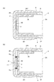
以下、具体的に説明する。本実施形態では、筐体2の、保護カバー2B、2Cが取り付けられる側面部の構造は、例えば図5に示すような構造になっている。なお、図5は、図1のY−Y線に沿う断面図である。また、図5中のAについては後で説明する。さらに、以下では、通気孔を、保護カバー2Bに設ける場合について説明するが、保護カバー2Cに設けてもよく、両方の保護カバー2B、2Cに設けることも可能である。
This will be specifically described below. In the present embodiment, the structure of the side surface of the
本実施形態では、図5に示すように、筐体2のハウジング本体部2Aの端部部分2A1に、内側カバー2bが取り付けられるようになっている。そして、この端部部分2A1の内側に内側カバー2bが挿入され、内側カバー2bに設けられた係止部2b1がハウジング本体部2Aの端部部分2A1の先端2A2に係止することにより、内側カバー2bによりハウジング本体部2Aの開口部が封止される。そして、内側カバー2bが挿入されたハウジング本体部2Aの端部部分2A1に、それらの外側からそれらを覆うように保護カバー2Bを取り付けることで、ハウジング本体部2Aの開口部が閉塞されるようになっている。
In the present embodiment, as shown in FIG. 5, the
また、本実施形態では、筐体2のハウジング本体部2Aの、保護カバー2Bが取り付けられる端部部分2A1が肉薄とされており、この部分に保護カバー2Bを取り付けた状態では、保護カバー2Bの外面と、ハウジング本体部2Aの外面(すなわち放射線入射面Rや裏面R*)とがほぼ面一になるようになっている。このように構成することで、例えば、ベッド上に横臥した患者とベッドとの間に放射線画像撮影装置1を挿入するような場合に、保護カバー2Bが患者の衣服に引っ掛からないようにすることが可能となる。
Further, in the present embodiment, the end portion 2A1 of the housing
なお、保護カバー2Bは、例えば樹脂等で形成することが可能であり、また、内側カバー2bは、マグネシウム(Mg)やアルミニウム(Al)等の金属で形成することが可能であるが、後述するように、他の材料で形成することも可能である。
The
本実施形態では、このような構成の下で、図5に示すように、保護カバー2Bと内側カバー2bにそれぞれ孔H1、H2が穿設され、それらが連通する位置に設けられることで、放射線画像撮影装置1の筐体2の側面に通気孔Hが形成されるようになっている。そして、単に通気孔Hを設けただけでは、通気孔Hを介して筐体2内に患者の尿等の液体が浸入してしまうため、通気孔Hに、筐体2内への液体の浸入を防止し、かつ通気を可能にするための通気フィルターFが設けられるようになっている。
In the present embodiment, under such a configuration, as shown in FIG. 5, holes H1 and H2 are formed in the
このように構成することで、筐体2の内外の空気の流通が、保護カバー2Bと内側カバー2bにそれぞれ設けられた各孔H1、H2で形成される通気孔Hを通り、通気フィルターFを介して行われるようになる。
With this configuration, the air flow inside and outside the
通気フィルターFとしては、上記のように、液体の流入を阻止し、かつ、筐体2の内外の空気を流通可能とするために、例えばPTFE(polytetrafluoroethylene、ポリテトラフルオロエチレン)多孔質膜等のフッ素樹脂系の膜等を用いることが可能であるが、上記の機能を有するものであればこれ以外の材料の通気性を有する膜等を用いることも可能である。
As described above, the ventilation filter F is made of, for example, a PTFE (polytetrafluoroethylene) porous film in order to prevent the inflow of liquid and to allow the air inside and outside the
また、図5では、通気フィルターFを保護カバー2Bと内側カバー2bとで単に挟むように構成するように記載されている。しかし、図示を省略するが、例えば、通気フィルターFと保護カバー2Bや内側カバー2bとを封止テープ等で接着する等して、通気フィルターFと保護カバー2Bとの間や、通気フィルターFと内側カバー2bとの間を通って液体が筐体2内に浸入しないように構成することも可能である。
Further, FIG. 5 shows that the ventilation filter F is simply sandwiched between the
なお、図5では、放射線画像撮影装置1における通気孔H等の実際の径や保護カバー2B等の各部材の実際の厚み等が必ずしも正確には反映されていない。また、通気孔Hの径を大きくし過ぎると、通気孔Hを介して筐体2内に液体が流入し易くなったり、通気孔Hが形成された部分の内部カバー2b等の強度が弱くなったり、外部から通気フィルターに指や突起物が触れて通気フィルターを破損したり、或いは外部からの汚れが付きやすくなったりするため、通気孔Hの径はそれらに悪影響を及ぼさないような適切な径とされる。
In FIG. 5, the actual diameter of the air holes H and the like of the
また、通気孔Hの形状は、本実施形態では円形とされるが、それ以外の形状に形成することも可能であり、適宜の形状に形成される。上記の理由により、通気孔Hの大きさは、その形状のうち、最も幅の狭い部分の幅が0.5〜5[mm]程度とすることが望ましい。円形の場合、直径0.5〜5[mm]程度とすることが望ましい。 Moreover, although the shape of the vent hole H is circular in this embodiment, it can also be formed in other shapes, and is formed in an appropriate shape. For the above reason, it is desirable that the size of the vent hole H is about 0.5 to 5 [mm] in the narrowest portion of the shape. In the case of a circular shape, the diameter is preferably about 0.5 to 5 [mm].
さらに、図5では、通気フィルターFを保護カバー2Bと内側カバー2bとで単に挟むように構成する例を示したが、図6(A)に示すように、保護カバー2Bには孔H1(図5参照)を設けず、内側カバー2bのみに孔H2を設け、内側カバー2bの孔H2の部分に通気フィルターFを設ける。そして、保護カバー2Bと内側カバー2bや筐体2のハウジング本体部2Aの端部部分2A1の間に、空気が通るために十分でかつ外部と通じる隙間を設け、その隙間を通じて通気するようにしてもよい。
5 shows an example in which the ventilation filter F is simply sandwiched between the
すなわち、この場合、内側カバー2bに設けた孔H2と、保護カバー2Bと内側カバー2bやハウジング本体部2Aの端部部分2A1との間の隙間とで、通気孔Hが形成される。そして、空気が、内側カバー2bに設けた孔H2や、保護カバー2Bと内側カバー2bや筐体2のハウジング本体部2Aの端部部分2A1の間の隙間を通り、Aの部分(図6(A)参照)を通って流入したり流出したりする状態になる。このように構成すれば、通気フィルターに直接指や突起物が触れて通気フィルターを破損したり、外部からの汚れが付きやすくなることを防止することが可能となる。
That is, in this case, the vent hole H is formed by the hole H2 provided in the
なお、上記のように保護カバー2Bと筐体2のハウジング本体部2Aの端部部分2A1との間に隙間を形成する場合、隙間を、内側カバー2bに孔H2が形成された部分にのみ形成し、保護カバー2Bの、隙間以外の部分をハウジング本体部2Aの端部部分2A1に密着させることで保護カバー2Bをハウジング本体部2Aの端部部分2A1に固定するように構成することが可能である。すなわち、図示を省略するが、例えば、保護カバー2Bの、ハウジング本体部2Aの端部部分2A1に対向する内面に溝を設けておき、保護カバー2Bの内面の溝以外の部分は、ハウジング本体部2Aの端部部分2A1に密着させ、溝の部分が上記の隙間になるように構成することが可能である。
As described above, when a gap is formed between the
また、保護カバー2Bを筐体2のハウジング本体部2Aの端部部分2A1から全体的に浮かせた状態(すなわち端部部分2A1から離れた状態)とし、保護カバー2Bの内面の所定の位置に内側に突起する凸部を設け、これらの凸部をハウジング本体部2Aの端部部分2A1に当接(或いは圧接)させることで保護カバー2Bをハウジング本体部2Aの端部部分2A1に固定するように構成することも可能である。
Further, the
或いは、図示を省略するが、保護カバー2Bを筐体2のハウジング本体部2Aの端部部分2A1から全体的に浮かせた状態とし、上記の凸部の代わりに保護カバー2Bの内面にパッキンを点在するように配置したり、或いは、保護カバー2Bの内面に上記のような溝を形成するようにパッキンを配置する等しておき、パッキンが保護カバー2Bとハウジング本体部2Aの端部部分2A1の両方に密着することで、保護カバー2Bとハウジング本体部2Aの端部部部分2A1との間に上記のような隙間を形成しつつ、保護カバー2Bをハウジング本体部2Aの端部部分2A1に固定するように構成することも可能である。
Or although illustration is abbreviate | omitted, the
また、防水機能をもたせた製品(すなわち放射線画像撮影装置1)を出荷前に検査しその密閉性を保証するために、エアリークテストと呼ばれる検査が一般に行われる。エアリークテストには大きく分けて内圧式と外圧式がある。内圧式では、製品内の圧力を加圧または減圧後、一定時間保持した前後の製品内圧力変化により、製品の空気漏れを検出し、密閉性を検査する。外圧式では、製品を密閉容器に入れ、密閉容器内の圧力を加圧または減圧後、一定時間保持した前後の密閉容器内圧力変化により、製品の空気漏れを検出し、密閉性を検査する。いずれの方式でも、製品の密閉性を空気の流入や流出によって検査するため、通気フィルターFが設けられている場合、そこから空気の流入や流出が生じてしまい、その他の防水機構の密閉性を正しく検査することができなくなる。 Further, in order to inspect a product having a waterproof function (that is, the radiation imaging apparatus 1) before shipment and guarantee its sealing property, an inspection called an air leak test is generally performed. The air leak test is roughly divided into an internal pressure type and an external pressure type. In the internal pressure type, after the pressure in the product is increased or decreased, air leakage of the product is detected by the change in the pressure in the product before and after being held for a certain time, and the sealing property is inspected. In the external pressure type, the product is put in a sealed container, and after the pressure in the sealed container is increased or decreased, air leakage of the product is detected by the change in pressure in the sealed container before and after being held for a certain time, and the sealing property is inspected. In any system, since the airtight filter F is provided in order to check the airtightness of the product by the inflow and outflow of air, the inflow and outflow of air will occur from there, and the airtightness of other waterproof mechanisms will be improved. The test cannot be performed correctly.
そのため、通気フィルターFが設けられている製品を、エアリークテストする場合、通気フィルターFを塞いでテストを行う必要がある。そして、例えば図5のような構造では、通気孔Hを例えば図示しないテープやパッキン付きの治具等で比較的容易に外部から塞ぐことが可能である。 Therefore, when an air leak test is performed on a product provided with the ventilation filter F, it is necessary to close the ventilation filter F and perform the test. In the structure as shown in FIG. 5, for example, the vent hole H can be relatively easily closed from the outside with a tape or a jig with packing (not shown).
また、図6(B)に示すように、保護カバー2Bと内側カバー2bにそれぞれ孔H1、H2を設け、内側カバー2bの孔H2を覆うように通気フィルターFを設けて、孔H1、H2で通気孔Hを形成するが、その際、例えば図6(B)に示すように、内側カバー2bと保護カバー2Bの間の、孔H2の周囲(この場合は通気フィルターFの周囲)の部分にパッキンPaを介在させて、内側カバー2bと保護カバー2BとパッキンPaとで区切られた空間sを形成するように構成することが可能である。
Further, as shown in FIG. 6B, holes H1 and H2 are provided in the
このように構成すれば、筐体2の内部への外気の流入や筐体2内部の空気の外部への流出が、保護カバー2Bと内側カバー2bにそれぞれ設けられた孔H1、H2と、内側カバー2bと保護カバー2BとパッキンPaとで区切られた空間sとを通り、通気フィルターFを介して行われるようになる。そのため、この場合は、保護カバー2Bと内側カバー2bの各孔H1、H2と、内側カバー2bと保護カバー2BとパッキンPaとで区切られた空間sとで、通気孔Hが形成されることになる。
If comprised in this way, the inflow of the external air to the inside of the housing | casing 2 and the outflow of the air inside the housing | casing 2 to the exterior will be carried out by the holes H1 and H2 provided in the
そして、上記のように、通気孔Hを図示しないテープやパッキン付きの治具等で比較的容易に外部から塞ぐことが可能となり、そのような状態でエアリークテストを行うことで、通気孔H以外の部分の防水機構の密閉性を正しく検査することが可能となる。 As described above, the vent hole H can be closed from the outside with a tape or a jig with a packing (not shown), and the air leak test is performed in such a state. It becomes possible to correctly inspect the sealing performance of the waterproof mechanism of this part.
なお、図6(B)や後述する図7(A)、(B)では、保護カバー2Bが筐体2のハウジング本体部2Aの端部部分2A1に密着するように構成されている場合が示されているが、図6(A)に示すように、それらの間に隙間を設けるように構成してもよい。また、図6(B)では、パッキンPaを、孔H2の周囲の部分、特に通気フィルターFの周囲の部分に設ける場合について説明したが、この他にも、例えば図7(A)に示すように、パッキンPaを、孔H2の周囲ではあるが、通気フィルターFに載せるように構成することも可能である。すなわち、保護カバー2Bと内側カバー2bとの間にパッキンPaと通気フィルターFとを介在させるように構成することも可能である。
In FIG. 6B and FIGS. 7A and 7B described later, a case where the
また、図6(B)や図7(A)では、内側カバー2bの孔H2の延長線上に保護カバー2Bの孔H1を形成する場合について説明したが、例えば図7(B)に示すように、保護カバー2Bの孔H1の中心軸と内側カバー2bの孔H2の中心軸とが互いにずれるように孔H1、H2を形成するように構成することも可能である。このように構成すれば、保護カバー2Bの孔H1を介して外部から指や突起物等が通気フィルターFに触れても、その部分では、通気フィルターFは内側カバー2bに固定されているため(すなわち孔H2の部分ではないため)、通気フィルターFが破損する等のリスクをより軽減することが可能となる。
6B and 7A, the case where the hole H1 of the
[作用]
次に、本実施形態に係る放射線画像撮影装置1の作用について説明する。本実施形態では、放射線画像撮影装置1を上記のように構成したため、例えば、放射線画像撮影装置1を標高が低い場所から標高が高い場所に搬送したり、或いは、航空機で上空を飛行して輸送する場合のように、外気圧が低い環境下に持ち込まれた場合、放射線画像撮影装置1の筐体2内の気圧が外気圧より高くなる。
[Action]
Next, the operation of the radiation
しかし、筐体2内の気圧が外気圧より高くなると、筐体2内の空気が通気孔Hを通過して筐体2外に流出する。そして、放射線画像撮影装置1の筐体2内の気圧が外気圧と同じ圧力になる。そのため、外気圧が低下しても、筐体2は膨張せず、筐体2の厚さが所定の厚さ(例えば前述したJIS規格サイズの13〜16[mm])に維持される。
However, when the air pressure in the
また、例えば、放射線画像撮影装置1がこのような外気圧が低い環境下から、標高が低い場所のように気圧が高い場所に持ち込まれた場合には、今度は、放射線画像撮影装置1の筐体2内の気圧が外気圧より低くなる。しかし、この場合も、外気が筐体2の通気孔Hを通過して筐体2内に流入する。そして、放射線画像撮影装置1の筐体2内の気圧が外気圧と同じ圧力になる。そのため、外気圧が上昇しても、筐体2は外気圧に押されて凹んだりせず、やはり筐体2の厚さが所定の厚さに維持される。
Further, for example, when the radiographic
そして、通気孔Hには通気フィルターFが設けられているため、放射線画像撮影装置1の筐体2に通気孔Hが設けられていても、通気フィルターFにより、患者の尿等の液体が通気孔Hを通って筐体2内に浸入することを的確に阻止することが可能となる。
Since the ventilation hole F is provided in the ventilation hole H, even if the ventilation hole H is provided in the
[効果]
以上のように、本実施形態に係る放射線画像撮影装置1によれば、筐体2に、通気孔Hを設け、しかも、通気孔Hに、筐体2内への液体の浸入を防止するための通気フィルターFを設けるように構成した。そして、通気孔Hは、筐体2の内外の空気を流通可能とするため、外気圧が低くなれば、通気孔Hを介して筐体2内から空気が流出する。また、外気圧が高くなれば、通気孔Hを介して筐体2内に空気が流入する。
[effect]
As described above, according to the radiographic
そのため、外気圧が変化しても、それに追従して筐体2内の気圧を変化させて筐体2内外の気圧を同じにすることが可能となるため、本実施形態に係る放射線画像撮影装置1によれば、外気圧が低下する等しても筐体2が膨張することを的確に防止することが可能となり、少なくとも筐体2の厚さを所定の厚さに維持することが可能となる。
Therefore, even if the external air pressure changes, the air pressure inside the
そして、このように筐体2が膨張することが的確に防止されるため、筐体2の膨張によってパッキンやシール等が剥がれたり損傷する等して、放射線画像撮影装置1の筐体2内に患者の尿等の液体が浸入できる状態になってしまうことを的確に防止することが可能となる。また、筐体2の膨張によって、装置内の部材が損傷したり正しく機能しなくなったり、或いは放射線画像撮影装置1を用いて画像を適切に撮影することができなくなる等の事態が生じることを的確に防止することが可能となる。
Since the expansion of the
[放射線画像撮影装置のグリップ性を向上させるための構成等について]
なお、本実施形態に係る放射線画像撮影装置1は、前述したように、持ち運び可能とした可搬型とされており(図1や図2等参照)、また、ブッキー装置51(図4参照)に装填せずに、単独の状態で、患者の身体にあてがったり、ベッド上に横臥した患者とベッドとの間に挿入したりして使用することができるようになっている。
[Configuration for improving the grip of radiographic imaging equipment]
As described above, the radiographic
また、本実施形態では、放射線画像撮影装置1の筐体2の裏面R*(図2等参照)側には、放射線画像撮影装置1の商品名や仕様等が記載された銘板が貼付されている。そして、放射線画像撮影装置1を患者とベッドとの間に挿入する等の作業中に銘板の角や端部がベッドや患者の衣服等に引っ掛からないようにするために、銘板を筐体2の裏面R*の一部に貼付するのではなく、筐体2の裏面R*の全面に貼付することで銘板の角等ができないように構成されている。
In the present embodiment, a name plate on which the product name, specifications, etc. of the
しかし、このように構成すると、放射線画像撮影装置1を扱う放射線技師等のユーザによっては、銘板が貼付された放射線画像撮影装置1の筐体2の裏面R*側が滑り易いと感じる可能性がある。そこで、筐体2の裏面R*側にグリップ部材を取り付けることができるように構成することが可能である。しかし、その場合、グリップ部材を単に筐体2の裏面R*に取り付けると、放射線画像撮影装置1を患者とベッドとの間に挿入する等の作業中にグリップ部材の角や端部がベッドや患者の衣服等に引っ掛かり、作業がしづらくなる可能性がある。また、グリップ部材は一般的にその表面の摩擦係数が大きいため、グリップ部材を銘板Ra*上に取り付けると、グリップ部材の摩擦係数の大きい面が、ベッドや患者の衣服等の面と直接的に触れることとなり、作業時の負荷が大きくなる虞れがある。
However, with this configuration, there is a possibility that a user such as a radiographer who handles the
そこで、例えば図8に示すように、放射線画像撮影装置1の筐体2の裏面R*に貼付された銘板Ra*の所定の位置(図8では所定の位置が筐体2の4辺の近傍の位置とされた場合が示されている。)に、グリップ部材Gを取り付けることができるようにするために、銘板Ra*を剥がすことができるように長円形(Rounded Rectangle、角丸長方形等ともいう。)に切れ込みCを入れることが可能である。
Therefore, for example, as shown in FIG. 8, a predetermined position of the nameplate Ra * affixed to the back surface R * of the
そして、これらの銘板Ra*の所定の位置のうち、グリップ部材Gを取り付ける位置の長円形の部分を剥がし、その部分に同形に形成したグリップ部材Gを貼付する等して取り付ける。図8では、グリップ部材Gが筐体2の短辺の近傍の2カ所に貼付された場合が例示されている。なお、グリップ部材Gを取り付けない場合は、長円形の各部分を剥がさない状態で放射線画像撮影装置1を使用する。
Then, among the predetermined positions of the nameplate Ra *, the oval portion at the position where the grip member G is attached is peeled off, and the grip member G formed in the same shape is attached to the portion and attached. In FIG. 8, the case where the grip member G is affixed in two places near the short side of the housing | casing 2 is illustrated. In addition, when the grip member G is not attached, the radiographic
このようにグリップ部材Gを取り付ける場合も、グリップ部材Gの表面や端部、或いは角部等がベッドや患者の衣服等に引っ掛かる等しないようにするために、グリップ部材Gは銘板Ra*の厚みと同等かそれ以下の厚みとされる。また、グリップ部材Gは、例えばゴム等のグリップ性の高い材質で形成することが可能である。また、グリップ部材Gの表面に凸部を有するエンボス構造としたり、或いはグリップ部材Gに単数または複数の孔を形成することで、グリップ性を高めるように構成することも可能である。その他、グリップ部材Gは、耐薬品性や耐スクラッチ性を有していたり、或いは汚れた際に清掃し易いように構成されていたり清掃し易い材質で形成されていることが好ましい。 Even when the grip member G is attached in this way, the grip member G has a thickness of the nameplate Ra * in order to prevent the surface, end, or corner of the grip member G from being caught on the bed or the clothes of the patient. The thickness is equal to or less than that. The grip member G can be formed of a material having a high grip property such as rubber. Further, the grip member G may be configured to have an embossed structure having a convex portion on the surface, or by forming a single hole or a plurality of holes in the grip member G so as to improve grip performance. In addition, it is preferable that the grip member G has chemical resistance and scratch resistance, or is configured to be easily cleaned when it becomes dirty, or formed of a material that is easy to clean.
上記のようにして、グリップ部材Gを放射線画像撮影装置1の筐体2の裏面R*に取り付けることができるように構成することで、放射線画像撮影装置1を持ち運んだり、患者とベッドとの間に挿入する等する際の放射線画像撮影装置1の操作性(すなわち把持性)をより向上させることが可能となる。
As described above, the grip member G can be attached to the back surface R * of the
また、放射線画像撮影装置1の筐体2の裏面R*に貼付された銘板の一部を剥がす等して筐体2の裏面R*に凹部を形成し、そこにグリップ部材Gを取り付けるように構成することで、グリップ部材Gが筐体2の裏面R*で外側に突出しないように(すなわち出っ張らないように)構成することが可能となる。そのため、放射線画像撮影装置1を患者とベッドとの間に挿入する際等に、グリップ部材Gが患者の衣服やベッド等に引っ掛かることを的確に防止することが可能となり、この点においても、放射線画像撮影装置1の操作性(この場合は挿入容易性)をより向上させることが可能となる。
Further, a part of the nameplate attached to the back surface R * of the
さらに、放射線画像撮影装置1の筐体2の裏面R*に貼付された銘板Ra*の所定の位置に、長円形等の切れ込みCを入れておき、それを剥がしてグリップ部材Gを取り付けることができるように構成することで、グリップ部材Gを取り付ける場合は、銘板Ra*の切れ込み部分を剥がしてグリップ部材Gを貼付する等して取り付けることで、筐体2にグリップ部材Gを容易かつ的確に取り付けることが可能となる。また、グリップ部材Gを取り付けない場合は、銘板Ra*の切れ込み部分を剥がさずにそのままの状態で放射線画像撮影装置1を使用することができる。そのため、いずれの場合も、放射線画像撮影装置1を的確に使用することが可能となり、放射線画像撮影装置1が、放射線技師等のユーザにとって使い勝手が良いものとなる。
Furthermore, an incision C such as an oval is put in a predetermined position of the nameplate Ra * affixed to the back surface R * of the
なお、上記の説明で、放射線画像撮影装置1の筐体2の裏面R*に銘板Ra*が貼付されている場合について説明したが、筐体2の裏面R*に貼付されているものは銘板である必要はなく、例えば保護用の薄板やフィルム等であってもよい。また、グリップ部材Gを取り付ける位置は任意であるなど、上記で説明した構成例に限定されない。さらに、上記では、放射線画像撮影装置1の出荷後にグリップ部材Gを取り付けることを前提について説明したが、放射線画像撮影装置1の出荷時に既にグリップ部材Gを取り付けておくように構成することも可能である。
Incidentally, in the above description, the rear surface of the
[放射線画像撮影装置の筐体の防水性を高めるための構成等について]
ところで、前述したように、放射線画像撮影装置1の筐体2内に患者の尿や血液等の液体が浸入すると、筐体2内に収納されたセンサーパネルSP(図2参照)上の電子部品32やPCB基板33、バッテリー36等がショートしたり部材に故障や劣化等を生じる等の悪影響が生じて、放射線画像撮影装置1が使えなくなる。
[About the configuration etc. to improve the waterproofness of the housing of the radiographic imaging device]
By the way, as described above, when a liquid such as a patient's urine or blood enters the
液体は、放射線画像撮影装置1の筐体2に存在する隙間や開口部から浸入する。そこで、本実施形態に係る放射線画像撮影装置1では、筐体2の防水が種々の形で図られている。
The liquid enters from a gap or an opening existing in the
[保護カバーの部分における防水構造]
例えば、本実施形態では、図5に示したように、筐体2のハウジング本体部2Aの端部部分2A1の内側に内側カバー2bが挿入され、それらを外側から保護カバー2Bで覆うようにしてハウジング本体部2Aの開口部が閉塞される(保護カバー2C(図1参照)側も同様)。
[Waterproof structure in the protective cover]
For example, in this embodiment, as shown in FIG. 5, the
しかし、このような構成では、保護カバー2Bと筐体2のハウジング本体部2Aの端部部分2A1との隙間から液体が浸入し、液体が筐体2のハウジング本体部2Aの端部部分2A1と内側カバー2bとの係止部分を通り、ハウジング本体部2Aの端部部分2A1と、それに挿入された内側カバー2bとの隙間を通って筐体2内に浸入し得ることが分かってきた。
However, in such a configuration, the liquid enters from the gap between the
このような保護カバー2Bの部分における液体の浸入を防止するための構成としては、例えば筐体2全体を防水用の袋やケース等内に収容する構成が考えられる。しかし、このように構成すると、袋やケース等に厚みがあるため、筐体2の放射線入射方向の厚さ寸法が、前述したJIS規格サイズすなわち13〜16[mm]の寸法範囲内に収まらなくなってしまう。筐体2全体を防水用のケース等に収容する場合、ケース等の分だけ放射線画像撮影装置1の重量が増えるため、放射線画像撮影装置1が重くなるという問題もある。
As a configuration for preventing the liquid from entering the
そのため、このように構成することは、少なくとも上記のように筐体2の放射線入射方向の厚さ寸法をJIS規格サイズで形成する限り、必ずしも有効な方法とは言い難い。なお、筐体2の放射線入射方向の厚さ寸法を、JIS規格サイズに制限せずに自由に構成できる場合には、この構成を採用することも可能である。
Therefore, such a configuration is not necessarily an effective method as long as at least the thickness dimension in the radiation incident direction of the
また、別の構成として、上記のような液体の浸入ルートの入口となる保護カバー2Bと筐体2のハウジング本体部2Aの端部部分2A1との間の開口部A(図5参照)に防水シートを貼付したりパッキンを挿入する等の構成も考えられるが、このような構成では必ずしも的確に液体に浸入を防止することができない。
As another configuration, the opening A (see FIG. 5) between the
そこで、図9(A)に示すように、筐体2のハウジング本体部2Aの端部部分2A1に内側カバー2bを挿入し、それらの外側からそれらを覆うようにテープ状の防水部材Tを貼付する。そして、それらの外側からそれらを覆うように保護カバー2Bを取り付けることで、ハウジング本体部2Aの開口部を閉塞するように構成することが可能である。なお、図9(A)には前述した通気孔Hや通気フィルターF等が記載されていないが、通気孔Hや通気フィルターFが必要に応じて適宜設けられることは言うまでもない。
Therefore, as shown in FIG. 9A, the
防水部材Tとしては、例えばゴムや片面粘着のテープ等を用いることも可能であるが、本実施形態では、防水性の両面テープ(以下、防水テープTという。)が用いられている。そして、筐体2のハウジング本体部2Aの端部部分2A1と、それに挿入された内側カバー2bの外側からそれらを覆うように防水テープTを貼付し、防水テープTの外側の面にフィルムを貼付する。このフィルムは、保護カバー2B側の粘着力をなくすことで保護カバー2Bを嵌め込み易くするとともに、防水テープT表面に汚れが付着しないようにし、かつ防水テープT表面の清掃性を向上させるためのものである。或いは、予めフィルムを片面に貼付した防水テープTを筐体2のハウジング本体部2Aの端部部分2A1や内側カバー2bの外側から貼付してもよい。そして、図9(A)に示したように、防水テープTの外側から保護カバー2Bが取り付けられる。
As the waterproof member T, for example, rubber or single-sided adhesive tape can be used, but in this embodiment, a waterproof double-sided tape (hereinafter referred to as waterproof tape T) is used. Then, the waterproof tape T is applied so as to cover the end portion 2A1 of the housing
このように構成すれば、筐体2のハウジング本体部2Aの端部部分2A1や内側カバー2bに保護カバー2Bを取り付ける前に、それらを外側から覆うように防水テープT等の防水部材Tを貼付して保護カバー2Bを取り付けることで、保護カバー2Bと筐体2のハウジング本体部2Aの端部部分2A1との隙間の部分に、防水部材Tを容易に取り付けることが可能となる。
If comprised in this way, before attaching the
また、このように防水部材Tを取り付けることで、仮に患者の尿等の液体が保護カバー2Bと筐体2のハウジング本体部2Aの端部部分2A1との間の開口部A(図9(A)参照)に浸入したとしても、防水部材Tが存在するため、液体がそれ以上奥に浸入すること、すなわち保護カバー2Bと筐体2のハウジング本体部2Aの端部部分2A1との隙間を通って液体が浸入することを的確に阻止することが可能となる。
Further, by attaching the waterproof member T in this way, it is assumed that a liquid such as a patient's urine is provided with an opening A (see FIG. 9A) between the
なお、例えば図9(B)に示すように、筐体2のハウジング本体部2Aの端部部分2A1の外面や内側カバー2bの外面等の防水テープTを貼付する面に、例えばネジScの頭等の凸部が存在する場合には、予め防水テープTの、当該凸部に対応する位置に、当該凸部の凸形状に沿うようにエンボス形状を設けておくことが可能である。このようにエンボス形状を設ければ、貼付面に存在する凸部の形状に追従するように防水テープTを貼付することが可能となり、防水テープTにシワが発生しなくなり、防水機能を維持することが可能となる。
For example, as shown in FIG. 9B, the head of the screw Sc, for example, is attached to a surface to which a waterproof tape T is affixed such as the outer surface of the end portion 2A1 of the
なお、このエンボス形状は、防水テープTのみに設けてもよいし、上記のように防水テープTの上にフィルムを貼る場合には、防水テープTとフィルムの両方に設けてもよい。また、予めフィルムを片面に貼った防水テープTにエンボス形状を設けておいてもよい。
また、貼り付け時の生産性の観点から、防水テープTに貼付するフィルムの厚みは30[μm]以上50[μm]以下であることが望ましい。
This embossed shape may be provided only on the waterproof tape T, or when the film is pasted on the waterproof tape T as described above, it may be provided on both the waterproof tape T and the film. Moreover, you may provide the embossing shape in the waterproofing tape T which stuck the film on the single side | surface previously.
In addition, from the viewpoint of productivity at the time of application, the thickness of the film to be applied to the waterproof tape T is desirably 30 [μm] or more and 50 [μm] or less.
[防水性を確認するための実験について]
なお、この保護カバー2Bの部分における防水構造のほか、前述した通気フィルターFが設けられた通気孔H(図5参照)や後述する放射線画像撮影装置1の各部における防水構造等においても同様であるが、本実施形態では、以下のような防水性に関する実験を行って、放射線画像撮影装置1の各部における防水性を確認するようにしている。
[Experiment to confirm waterproofness]
In addition to the waterproof structure in the
この場合、実験では、放射線画像撮影装置1を、深さ30[mm]の水中に浸漬させ、放射線入射面R(図1や図2参照)側から60[kg]の荷重を加えた状態で10分間放置した後、60[kg]の荷重を除去する。そして、その後、筐体2内への水の浸入の有無、および水の浸入があった場合には浸入箇所を確認する。なお、60[kg]の荷重は、体重130[kg]の患者が例えば臀部を放射線画像撮影装置1の放射線入射面R上に載置する状態で横臥した場合に放射線入射面Rに加わる荷重に相当する。
In this case, in the experiment, the
すなわち、このような実験条件は、そのような体重の患者が放射線入射面R上に横臥して放射線画像撮影装置1の筐体2が変形するような過酷な状態であり、しかも、放射線画像撮影装置1が患者の尿等に浸かってしまうような状態であっても、少なくとも10分間は筐体2内への液体の浸入がないことを保証するための条件として設定されている。
That is, such an experimental condition is a severe state in which a patient having such a weight lies on the radiation incident surface R and the
そして、上記の実験条件の下で筐体2への水の浸入が認められない場合に、放射線画像撮影装置1の筐体2の防水性が担保されていると判断される。上記の保護カバー2Bの部分における防水構造や、通気フィルターFが設けられた通気孔Hの構成、或いは後述する放射線画像撮影装置1の各部における防水構造等は、全て上記の実験を行ってその防水性が担保されたものである。
Then, when water does not enter the
[スイッチ等の部分における防水構造]
また、図1に示したように、保護カバー2Bには、電源スイッチ37や切替スイッチ38、インジケーター40等が設けられている。そして、これらのスイッチやインジケーター等を設ける場合、図示を省略するが、通常の場合、保護カバー2Bに孔を開け、そこからスイッチのボタン部分を内側から外側に突出させたり、インジケーターを設ける際には保護カバー2Bに設けた孔や窓から内側のLED等の発光が見えるように構成される。
[Waterproof structure in parts such as switches]
As shown in FIG. 1, the
しかし、このように構成すると、保護カバー2Bに設けた孔や窓の周囲の部分等から液体が筐体2内に浸入する。そこで、例えば、以下のようにして、この部分からの液体の浸入を防止するように構成することが可能である。
However, when configured in this way, the liquid enters the
すなわち、図示を省略するが、まず、従来の場合と同様に、電源スイッチ37や切替スイッチ38等のボタンやインジケーター40を構成するLED等を配置した基板を、前述した内側カバー2b(図9(A)等参照)等に取り付ける。また、図10に示すように、保護カバー2Bの対応する位置に、予め開口(図中の破線参照)を設けておく。そして、上記のようにして筐体2のハウジング本体部2Aの端部部分2A1に、基板が取り付けられた内側カバー2bを取り付け、それらを覆うように保護カバー2Bを取り付けると、図10では図示を省略するが、基板に取り付けられたボタンやLED等が保護カバー2Bの開口を介して外部に露出する状態になる。
That is, although not shown, first, as in the conventional case, the board on which the buttons such as the
そして、その状態で、図10に示すように、ボタンやLED等に対応する位置に凸部が設けられたエンボスシート等の防水シートSを、保護カバー2Bの開口を塞ぐように保護カバー2Bに外側から貼付する。或いは防水シートSを保護カバー2Bの内側から貼付するように構成することも可能であるが、いずれにせよ、防水シートSにより保護カバー2Bに設けられた開口から液体が筐体2内に浸入することを阻止するように構成される。その際、防水シートSのインジケーター40に対応する部分を透明或いは半透明とし、内部のLED等の発光を視認することができるようにすること等は、改めて説明するまでもない。
In this state, as shown in FIG. 10, a waterproof sheet S such as an embossed sheet provided with a convex portion at a position corresponding to a button, LED, or the like is applied to the
このように構成すれば、防水シートSにより、保護カバー2Bの、電源スイッチ37や切替スイッチ38、インジケーター40等に対応する部分から液体が筐体2内に浸入することを的確に防止することが可能となる。また、防水シートSを貼付するだけでよいため、保護カバー2Bの当該部分から液体が筐体2内に浸入することを容易に防止することが可能となる。
With this configuration, the waterproof sheet S can accurately prevent liquid from entering the
また、保護カバー2bの内側においては、内側カバー2bに取り付けられた、ボタンやLED等を配置した基板(以下、簡単にLED基板という。)を覆うように、図9(A)に示した防水テープTを貼り付けることで、LED基板への水分の付着や、内側カバー2bに開けられた開口(図10の破線参照)を介した装置内部への液体の浸入を防ぐことができる。
Further, on the inner side of the
また、その場合、LED基板全体を覆うように防水テープTが存在すると、防水テープTが透明でない場合には防水テープTによりLEDの光の透過が遮られることが問題となる場合がある。また、防水テープTの厚みが厚い場合、ボタンを押す感触へ悪影響を及ぼす場合がある。そこで、例えば図10(B)に示すように、LED基板Kを覆う範囲のみ、防水テープTの両面テープを無くし、フィルムFiのみとするように構成することが可能である。 In that case, if the waterproof tape T is present so as to cover the entire LED substrate, the waterproof tape T may block the light transmission of the LED when the waterproof tape T is not transparent. Further, when the waterproof tape T is thick, it may adversely affect the feeling of pressing the button. Therefore, for example, as shown in FIG. 10B, the double-sided tape of the waterproof tape T can be eliminated and only the film Fi can be formed only in the range covering the LED substrate K.
このように構成すれば、フィルムFiを介してLEDの光を透過させることが可能となるとともに、ボタンを押す感触を良好にすることが可能となる。また、フィルムFiはLED基板K上のボタンの部分において、ボタン部品の高さに沿うように凸状のエンボス形状としてもよい。フィルムFiにエンボス形状を形成せずフラットに形成すると、フラットのフィルム面の張力によってボタンが押下されてしまう可能性があるが、上記のようにフィルムFiのボタンの部分にエンボス形状を形成すれば、フィルムFiによりボタンが押下されてしまうことを防止することが可能となる。また、それとともに、ボタンを押す感触をより良好なものとすることが可能となる。 If comprised in this way, while being able to permeate | transmit the light of LED through the film Fi, it becomes possible to make the feeling which pushes a button favorable. Further, the film Fi may have a convex emboss shape at the button portion on the LED substrate K so as to follow the height of the button component. If the film Fi is formed flat without forming an embossed shape, the button may be pressed by the tension of the flat film surface. However, if the embossed shape is formed on the button portion of the film Fi as described above. It is possible to prevent the button from being pressed by the film Fi. At the same time, it is possible to improve the feeling of pressing the button.
[コネクターの部分における防水構造]
また、図1に示したように、放射線画像撮影装置1の筐体2には、コネクター39も設けられており、このコネクター39の部分から液体が筐体2内に浸入する可能性もある。そこで、このコネクター39部分からの液体の浸入を、パッキンを用いて阻止するように構成することが可能である。
[Waterproof structure in the connector part]
Further, as shown in FIG. 1, the
本実施形態に係る放射線画像撮影装置1では、コネクター39に、例えばブッキー装置51のコネクター51b(図4参照)等の外部のコネクターを接続する際に、外部のコネクターが放射線画像撮影装置1のコネクター39に的確に接続されるようにするために、図11に示すように、コネクター39の近傍に位置決め用の凹部39Aが設けられている。そして、外部のコネクターには突起部(図示省略)を設けておき、接続の際に、外部のコネクターには突起部を放射線画像撮影装置1のコネクター39の凹部39Aに挿入することで、放射線画像撮影装置1のコネクター39に対する外部のコネクターの位置決めを行って適切に接続するようになっている。本実施形態では、この位置決め用の凹部39Aは、ガイド板39Bの所定の位置を凹ませることで、ガイド板39Bに一体的に形成されるようになっている。
In the
そして、前述した内側カバー2bの所定の箇所に開口を設けておき、図11に示すように、コネクター用の開口に内側からコネクター39を嵌め込む。また、凹部用の開口にガイド板39Bの凹部39Aを外側から嵌め込む。そして、ガイド板39Bと、コネクター39の内側に配置した支持板39Cとをネジ39Dで螺着することにより、コネクター39を内側カバー2bに押し付けて位置固定するようになっている。
And the opening is provided in the predetermined location of the
そこで、図11に示すように、ガイド板39Bと内側カバー2bとの間にゴム等のパッキン39Eを介在させてネジ39Dで締め付けることによって、このコネクター39の部分からの液体の浸入を的確に防止することが可能となる。なお、コネクター39が内側カバー2bに係止されている部分(図11の39a参照)や、ネジ39Dとガイド板39Dとの間等も、パッキンやシール材、防水テープ等で適宜防水される。また、ガイド板39Aと、図11では図示を省略した保護カバー2B(図9(A)等参照)との間も、パッキンやシール材、防水テープ等で適宜防水される。
Therefore, as shown in FIG. 11, a
このように構成することで、パッキン39Eにより、コネクター39の部分から液体が筐体2内に浸入することを的確に防止することが可能となる。また、パッキン39Eを介在させた状態でネジ39Dで螺着するだけでよいため、コネクター39の部分から液体が筐体2内に浸入することを容易に防止することが可能となる。
With this configuration, the
[筐体の角部の構造]
[保護カバーの端部の部分の構成]
ところで、放射線画像撮影装置1の筐体2の4カ所の角部には、上記のスイッチ等(すなわち電源スイッチ37や切替スイッチ38、インジケーター40等)やコネクター39等のような構造は存在せず、保護カバー2Bに開口(図10の破線参照)は設けられない。そのため、上記のスイッチ等の部分における防水構造やコネクターの部分における防水構造のように保護カバー39に設けた開口を防水シートS(図10参照)やパッキン39E(図11参照)等で塞ぐ必要はない。
[Structure of the corner of the housing]
[Configuration of the edge of the protective cover]
By the way, there are no structures such as the above-described switches (that is, the
一方、本実施形態では、放射線画像撮影装置1を落下させてしまい、筐体2の角部が床面等にぶつかった際の振動や衝撃によって筐体2内のセンサーパネルSP(図2参照)が損傷しないようにするために、放射線画像撮影装置1の筐体2の角部を、以下で説明するような特殊な構造としており、その特殊な構造のために筐体2の角部から液体が筐体2内に浸入する可能性が生じる。そのため、そのような構成を採用する際にも、適切に防水を図ることが必要になる。
On the other hand, in the present embodiment, the radiation
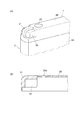
以下、本実施形態に係る放射線画像撮影装置1における筐体2の角部の構成等について説明する。なお、以下においても、保護カバー2Bの場合について説明し、保護カバー2C(図1参照)については説明を省略するが、保護カバー2Cも同様に構成される。図12(A)は、放射線画像撮影装置の筐体の角部の外観を表す斜視図であり、図12(B)は保護カバーの端部の断面図である。
Hereinafter, the structure of the corner | angular part of the housing | casing 2 in the
本実施形態では、図12(A)、(B)に示すように、筐体2の角部部分に相当する保護カバー2Bの端部の角部には、1本の畝状の凸部21が、保護カバー2Bの長さ方向に延在するように設けられている。
In the present embodiment, as shown in FIGS. 12A and 12B, a single hook-shaped
放射線画像撮影装置1の筐体2の角部である保護カバー2Bの端部にこのような畝状の凸部21を設けると、例えば放射線画像撮影装置1を落下させて、筐体2の角部が床面等にぶつかった際に、保護カバー2Bの端部の畝状の凸部21の部分がその衝撃で破壊される。そして、床面への衝突の衝撃のエネルギーの一部が、上記のように保護カバー2Bの畝状の凸部21が破壊されてその部分で吸収される。
When such a bowl-shaped
そのため、放射線画像撮影装置1の筐体2に加わる衝突のエネルギーが軽減されるため、放射線画像撮影装置1を落下させた際に筐体2内のセンサーパネルSP(図2参照)に加わる衝撃や振動を軽減することが可能となり、放射線画像撮影装置1の落下によりセンサーパネルSPが損傷することを的確に防止することが可能となる。
Therefore, since the energy of the collision applied to the
放射線画像撮影装置1を落下させた際に、筐体2の角部である保護カバー2Bの端部の部分が破壊されないと、その部分で受けた衝撃のエネルギーが筐体2やセンサーパネルSP(図2参照)に伝わって、センサーパネルSPが損傷してしまう。そのため、放射線画像撮影装置1を落下させた際に、保護カバー2Bの端部の部分が破壊されることで、落下の衝撃のエネルギーを吸収するように構成することが必要である。
If the end portion of the
しかし、放射線画像撮影装置1を落下させた際に、逆に、保護カバー2Bの端部の部分が容易に破壊されてしまうと、保護カバー2Bの端部の部分で落下の衝撃のエネルギーを十分に吸収することができなくなり、結局、落下の衝撃のエネルギーがそのまま筐体2に伝わり、センサーパネルSPに伝わってしまう。そのため、保護カバー2Bの端部の部分は、落下の衝撃による変形に対する強さをある程度有するように形成して、放射線画像撮影装置1を落下させた際のエネルギーを十分に吸収するように構成する必要もある。
However, when the radiographic
これらの点について本発明者らが研究を重ねた結果、上記のように、放射線画像撮影装置1の筐体2の角部である保護カバー2Bの端部に、図12(A)、(B)に示したような畝状の凸部21を設ける構成が望ましいことが分かった。そして、畝状の凸部21の部分の幅や厚み等を調整することで、放射線画像撮影装置1を落下させた際の保護カバー2Bの端部の部分の破壊され易さ(或いは破壊されにくさ)や、保護カバー2Bの端部の部分での落下の衝撃のエネルギーの吸収効率を調整することが可能となる。
As a result of the researches conducted by the present inventors on these points, as described above, the end of the
また、図12(A)に示すように、保護カバー2Bの端部に畝状の凸部21を形成するため、畝状の凸部21以外の部分が凹状に形成されている。そのため、保護カバー2Bの端部の部分が内側に凸になっているが(図12(B)参照、)、この畝状の凸部21以外の凹状の部分(すなわち内側に凸の部分)22やその周辺の部分を、保護カバー2Bの他の部分の厚みよりも分厚く形成することも可能である。
Further, as shown in FIG. 12 (A), in order to form the hook-shaped
畝状の凸部21以外の部分が凹状の部分22やその近傍の部分を肉厚に形成すると、上記のように、保護カバー2Bの端部の部分の、落下の衝撃による変形に対する強さをより強くすることが可能となる。そして、この部分の厚みを調整することで、放射線画像撮影装置1を落下させた際の保護カバー2Bの端部の部分の破壊され易さや、保護カバー2Bの端部の部分での落下の衝撃のエネルギーの吸収効率を調整することが可能となる。
When the portion other than the bowl-shaped
なお、保護カバー2Bの端部の畝状の凸部21は、図12(A)等に示したように1本のみ形成することも可能であるが、複数本の畝状の凸部21を並列に設けたり、或いは複数本の畝状の凸部21をいわばワッフル状に交差させるように設けることも可能である。また、図12(A)における23は、保護カバー2Bを図示しない内側カバー2b(図5や図9(A)参照)に螺着するためのネジを表し、図12(B)における23aや後述する図13(A)、(B)の23bは、それぞれネジ23のためのネジ孔を表す。また、ネジ23を螺着する際、その部分から液体が浸入しないようにするために、パッキンやシール材を介在させる等の防水のための措置が講じられることは上記と同様である。
Note that only one hook-shaped
[ハウジング本体部の角部の構造]
一方、上記のように保護カバー2Bの端部の部分に畝状の凸部21を設けて破壊可能に形成する際に、前述した図9(A)に示したように、保護カバー2Bの端部の部分で筐体2のハウジング本体部2Aの端部部分2A1を外側から覆うように構成すると、保護カバー2Bの畝状の凸部21のすぐ近傍にハウジング本体部2Aの端部部分2A1が存在することになる。
[Structure of the corner of the housing body]
On the other hand, as shown in FIG. 9A, when the hook-shaped
しかし、このような構成では、放射線画像撮影装置1を落下させて筐体2の角部が床面等にぶつかり、その衝撃で保護カバー2Bの端部が破壊されたとしても、その衝撃がハウジング本体部2Aの端部部分2A1にも加わってしまう。そして、その衝撃が端部部分2A1からハウジング本体部2A全体に伝わってしまい、結局、筐体2やその内部に収容されたセンサーパネルSPが大きな衝撃を受けてしまうことになる。
However, in such a configuration, even if the radiation
そこで、保護カバー2Bの端部の部分を上記のように破壊可能に構成する場合には、それとともに、図13(A)に示すように、筐体2の角部の部分のハウジング本体部2の端部部分2A1を切り欠いて切り欠き部2A3を設けるように構成される。なお、図示を省略するが、ハウジング本体部2Aの端部部分2A1に保護カバー2Bが取り付けられる際、このハウジング本体部2Aの角部の端部部分2A1の切り欠き部2A3に、保護カバー2Bの端部の内側に凸になった部分22(図12(B)参照)が配置される状態になる。そのため、保護カバー2Bの端部の内側に凸になった部分22とハウジング本体部2Aの端部部分2A1とが干渉しあわないようになっている。
Therefore, in the case where the end portion of the
なお、図13(A)では、放射線画像撮影装置1の筐体2のハウジング本体部2Aの端部部分2A1に内側カバー2bが挿入され、それらの外側からそれらを覆うようにテープ状の防水部材Tを貼付された状態が示されている。また、保護カバー2Bの図示は省略されている。
In FIG. 13A, an
[ハウジング本体部の切り欠き部における防水構造]
以上のように、本実施形態に係る放射線画像撮影装置1では、放射線画像撮影装置1を落下させて、筐体2の角部が床面等にぶつかっても、その際の衝撃や振動によって筐体2内のセンサーパネルSPが損傷しないようにするために、筐体2の角部、すなわち保護カバー2Bの端部の部分に畝状の凸部21等を設けたり(図12(A)、(B)参照)、筐体2のハウジング本体部2Aの角部の端部部分2A1に切り欠き部2A3(図13(A)参照)を設けたりする特殊な構造を有している。
[Waterproof structure at the notch in the housing body]
As described above, in the radiographic
そして、このように、筐体2のハウジング本体部2Aの角部の端部部分2A1に切り欠き部2A3を設けるように構成すると、切り欠き部2A3を介して筐体2に液体が浸入することが可能な状態になる。そのため、この切り欠き部2A3を防水する構成が必要になる。
If the notch 2A3 is provided in the end portion 2A1 at the corner of the housing
そこで、本実施形態では、例えば図13(B)に示すように、ハウジング本体部2Aの角部の切り欠き部2A3を封止するために、防水キャップ24を切り欠き部2A3に取り付けるように構成される。
Therefore, in the present embodiment, for example, as shown in FIG. 13B, the
この場合、防水キャップ24は、例えば熱可塑性ポリウレタン(TPU)等の軟らかい樹脂等で形成することが可能である。また、例えば上記のように保護カバー2Bの端部の部分に畝状の凸部21(図12(A)、(B)参照)を設けただけでは、筐体2が床面等にぶつかった際の衝撃のエネルギーの吸収が不十分であるような場合には、この防水キャップ24を、例えば金属等の、落下の衝撃による変形に対する強さをある程度有するような材料で形成することも可能である。
In this case, the
また、前述したように、本実施形態では、ハウジング本体部2Aの端部部分2A1や内側カバー2bを外側から覆うように貼付された両面テープ(防水部材T)の外側の面には、保護カバー2Bを嵌め込み易くするためにフィルムが貼付されているが、防水キャップ24を取り付ける部分ではこのフィルムを剥がし、防水キャップ24を両面テープ(防水部材T)の外側の面に貼り付けるようにして取り付けることが可能である。或いは、この部分では両面テープを剥がしてハウジング本体部2Aの端部部分2A1を露出させ、露出させた端部部分2A1等に防水キャップ24を接着して取り付けるように構成することも可能である。或いは、両面テープ(防水部材T)の外側の面に貼付されたフィルムの上から、防水キャップ24を接着して取り付けてもよい。
Further, as described above, in the present embodiment, the protective cover is provided on the outer surface of the double-sided tape (waterproof member T) that is attached so as to cover the end portion 2A1 of the housing
そして、このように構成することで、放射線画像撮影装置1を落下させた際の衝撃が筐体2のハウジング本体部2Aに直接伝わらないようにするために、ハウジング本体部2Aの端部部分2A1に切り欠き部2A3を設けるように構成する場合でも、切り欠き部2A3を防水キャップ24で封止することで、切り欠き部2A3から液体が筐体2内に浸入することを的確に防止することが可能となる。
With this configuration, the end portion 2A1 of the housing
ところで、上記のように、例えば防水キャップ24(図13(B)参照)を金属で形成すると、金属が硬いため、筐体2が床面等にぶつかる等して保護カバー2B(図12(A)、(B)等参照)の角部が内側に変形し、保護カバー2Bの角部とその内側の防水キャップ24とがぶつかった際の衝撃が筐体2を伝わって筐体2内のセンサーパネルSP(図2参照)等にも伝わってしまう可能性がある。或いは、保護カバー2Bの角部が内側に変形し、それに押されて内側にある防水キャップ24も変形することにより、防水キャップ24と筐体2を接合している接着剤等の剥がれが生じ、防水性が損なわれる虞れがある。
By the way, as described above, for example, when the waterproof cap 24 (see FIG. 13B) is made of metal, since the metal is hard, the
また、上記のように、例えば防水キャップ24を軟らかい樹脂等で形成すると、筐体2が床面等にぶつかる等して保護カバー2Bの角部が内側に押された際に、その衝撃で防水キャップ24に破断が生じる可能性がある。
Further, as described above, for example, when the
すなわち、例えば図13(B)に示したように筐体2のハウジング本体部2Aの端部部分2A1に設けた切り欠き部2A3の開口を封止するように軟らかい樹脂等で形成した防水キャップ24を取り付け、図12(A)、(B)に示したようにそれを外側から覆うように保護カバー2Bを嵌め込むと、図14の断面図の左下に示すように、防水キャップ24の端部σの部分が、保護カバー2Bの内側に凸の部分22と筐体2の側面2Dとの間に挟まれたり、図14の断面図の右上に示すように、防水キャップ24の端部σの部分が、保護カバー2Bの内側に凸の部分22と内側カバー2bやハウジング本体部2Aの端部部分2A1との間に挟まれる状態になる。
That is, for example, as shown in FIG. 13B, a
そして、この状態で筐体2が床面等にぶつかる等して、図14中に太い矢印で示すように保護カバー2Bの角部に強い力が加わると、防水カバー24の端部σの部分がそれぞれ保護カバー2Bと筐体2の側面2Dや内側カバー2b等との間で強い力で挟み付けられる状態になる。そのため、軟らかい樹脂等で形成された防水キャップ24に(特に端部σの部分で)破断が生じてしまい、防水性が損なわれてしまう可能性がある。
In this state, when a strong force is applied to the corner of the
そこで、例えば図15(A)に示すように、防水キャップ24の、図15(A)では図示を省略した保護カバー2Bと筐体2の側面2Dや内側カバー2b等との間で挟まれる端部σを含む周縁部24Aを金属材で形成し、保護カバー2Bに強い力が加わった際に保護カバー2Bで押される中央部24Bを軟らかい樹脂等の軟質材で形成することが可能である。
Therefore, for example, as shown in FIG. 15A, the end of the
このように構成すれば、上記のように防水キャップ24の端部σの部分が保護カバー2Bと筐体2の側面2Dや内側カバー2b等との間で挟まれても、その部分が金属材で形成されているため、破断しにくくなる。また、筐体2が床面等にぶつかる等して保護カバー2B(図15(B)等参照)の角部が内側に変形しても、内側に変形した保護カバー2Bの角部に押されるのは、防水キャップ24の軟質材で形成された中央部24Bであるため、保護カバー2Bが防水キャップ24の中央部24Bにぶつかっても、その衝撃が筐体2や内部のセンサーパネルSP等にも伝わらないようにすることが可能となる。
If comprised in this way, even if the part of the edge part (sigma) of the
しかし、防水キャップ24を図15(A)に示したように形成しても、筐体2が床面等にぶつかる等して保護カバー2Bの角部に強い力が加わった際に、防水キャップ24の金属材で形成された周縁部24A(すなわち端部σの部分)が保護カバー2Bと筐体2の側面2Dや内側カバー2b等との間で強い力で挟み付けられると、破断が生じる可能性は完全にはなくならない。
However, even if the
また、図14に示したように防水キャップ24全体が金属で形成されている場合には、保護カバー2Bの角部に強い力が加わると、図14の左側の、保護カバー2Bが防水カバー24や筐体2の側面2Dと当接している部分に、上記のような防水キャップ24を挟み付ける力だけでなく、図中に矢印Iで示すように右側に押し込む力が生じる。また、図14の上側の、保護カバー2Bが、防水カバー24や内側カバー2b等と当接している部分にも、防水キャップ24を挟み付ける力だけでなく、図中に矢印Jで示すように下側に押し込む力が生じる。そのため、結果的に、防水キャップ24の周縁部24Aを外側に拡げるような力が働くことになり、前述したように、防水キャップ24と筐体2を接合している接着剤等の剥がれが生じ、防水性が損なわれる場合がある。
In addition, when the
そして、このような現象は、図15(A)に示したように防水キャップ24の周縁部24Aを金属材で形成した場合にも同様に生じ、保護カバー2Bの角部に強い力が加わると、防水キャップ24の周縁部24Aに図14に矢印I、Jで表したような方向に力が生じる。そのため、結果的に、防水キャップの周縁部24Aの、図15(A)にτで示す部分を外側に拡げるように力が働くようになるため、防水キャップ24の周縁部24Aのτの部分で、防水キャップ24とハウジング本体部2Aの端部部分2A1等との接着が外れてしまい、その部分で防水性が損なわれてしまう場合があり得る。
Such a phenomenon also occurs when the
そこで、前述した図14の断面図の左下に示した部分では、筐体2の側面2Dの端部(図14では上端部)と、その部分に固定される防水キャップ24の端部σの部分とが、筐体2の側面2Dの法線方向に形成されていたが、これをやめて、例えば図15(B)の断面図の左下に示すように、筐体2の側面2Dの端部と、その部分に固定される防水キャップ24の周縁部24A(すなわち端部σの部分)とが、筐体2の側面2Dの法線方向に対して傾斜するように形成することが可能である。
Therefore, in the portion shown in the lower left of the cross-sectional view of FIG. 14 described above, the end portion (upper end portion in FIG. 14) of the
このように構成すると、筐体2が床面等にぶつかる等して、図15(B)中に太い矢印で示すように保護カバー2Bの角部に強い力が加わった場合、図15(B)の断面図の左下に示す防水カバー24の周縁部24Aの部分(すなわち端部σの部分)では、筐体2の側面2Dの端部や防水キャップ24の周縁部24Aが傾斜しているため、保護カバー24が外側に逃げるように力が働く。或いは、少なくとも、保護カバー24が内側に入り込もうとする力(前述した図14の矢印I参照)が弱まるため、防水キャップ24の周縁部24A(すなわち端部σの部分)で破断が生じることを防止することが可能となる。
With this configuration, when a strong force is applied to the corner portion of the
なお、この防水キャップ24の周縁部24Aや筐体2の側面2Dの端部に設ける傾斜を、例えば図15(B)の断面図の右上の端部σの部分に形成することも可能であり、また、防水キャップ24の周縁部24Aの全周にわたって形成するように構成することも可能である。
In addition, it is also possible to form the inclination provided in the
このように構成すれば、筐体2が床面等にぶつかる等して保護カバー2Bの角部に強い力が加わった際に、上記のように防水キャップ24の周縁部24Aが外側に拡がる代わりに、保護カバー2Bが外側にずれるため、防水キャップの周縁部24A、特に図15(A)にτで示す部分が外側に拡がって防水性が損なわれてしまうことを的確に防止することが可能となる。
If comprised in this way, when strong force is added to the corner | angular part of the
[センサー基板等のV字割れを防止するための構成等について]
上記では、放射線画像撮影装置1を落下させ、筐体2の角部が床面等にぶつかった際の衝撃や振動が筐体2内のセンサーパネルSP(図2参照)に伝わってセンサーパネルSPが損傷する場合があり、それを防止するための構成(すなわち保護カバー2Bにおける畝状の凸部21等)を設けること等について説明した。
[Configurations to prevent V-shaped cracking of sensor substrates, etc.]
In the above, the shock and vibration when the radiographic
このように放射線画像撮影装置1を落下させた場合にもセンサーパネルSPが損傷し得るが、この他にも、例えば、放射線画像撮影装置1の放射線入射面R等に局所的な力が加わるような場合にも、センサーパネルSPが損傷し得る。これは、例えばベッドの上に置いた放射線画像撮影装置1上に、ストレッチャー等で運ばれてきた患者が乱暴に載せられる等して、例えば放射線画像撮影装置1の放射線入射面Rに患者の臀部から強い力が加わるような場合に生じ得る。
The sensor panel SP can be damaged even when the
そして、このように放射線画像撮影装置1の筐体2の放射線入射面Rの中央部等に局所的な強い力が加わると、筐体2やその内部のセンサーパネルSPにV字状に折り曲げるような力が加わる場合がある(後述する図17(A)参照)。そして、センサーパネルSPにこのような力が加わると、ガラス基板で構成されたセンサー基板4やシンチレーター基板34(図2参照)にいわゆるV字割れが生じてしまう。そのため、このように、放射線画像撮影装置1の筐体2にV字状に折り曲げるような力が加わる場合にも、センサーパネルSPが損傷し得る。
When a strong local force is applied to the central portion of the radiation incident surface R of the
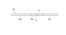
一方、図1に示したように、例えば、放射線画像撮影装置1の筐体2を構成する一方の保護カバー2Cの側に示したように、保護カバー2Cの長手方向の略中央の部分βにアンテナ41(図4参照)が設けられる場合がある。そして、アンテナ41を筐体2内に内蔵させるために、前述した内側カバー2b(図5や図9(A)等参照)の内側にアンテナ41を設ける場合がある。
On the other hand, as shown in FIG. 1, for example, as shown on the side of one protective cover 2C constituting the
このような場合に、前述したように内側カバー2bをマグネシウム(Mg)やアルミニウム(Al)等の金属で形成すると、金属製の内側カバー2bにより、アンテナ41が電波を発信したり受信したりすることができなくなるため、例えば図16に示すように、内側カバー2bのうち、アンテナ41を設ける部分以外の部分2baをマグネシウム等の金属で形成し、アンテナ41を設ける部分2bbを樹脂等で形成し、2つの金属製の部分2baと1つの樹脂等で形成された部分2bbとをつなぎ合わせて内側カバー2bを形成する場合があった。
In such a case, when the
しかし、図16に示したように内側カバー2bをいわば3分割するようにして形成すると、樹脂等で形成された内側カバー2bの部分2bbや、各部分2ba、2bbの継ぎ目の部分が相対的に弱くなる。そして、例えば、上記のように、放射線画像撮影装置1上に患者が乱暴に載せられる等して、放射線画像撮影装置1の筐体2の放射線入射面Rの中央部等に局所的な強い力が加わると、図17(A)にイメージ的に示すように、上記のように強度が弱い部分で筐体2がV字状に折り曲げられ易くなり、前述したように、センサー基板4やシンチレーター基板34等のガラス基板にV字割れが生じて、センサーパネルSPが損傷してしまう。
However, when the
そこで、内側カバー2bを、図16に示したように3分割構造とせず、例えば繊維強化プラスチックで一体的に形成するように構成することが可能である。この場合、例えば炭素繊維強化プラスチック(carbon-fiber- reinforced plastic:CFRP)を用いると、炭素繊維によりアンテナ41による電波の送受信が妨害されてしまうため、ガラス繊維強化プラスチック(glass-fiber- reinforced plastic:GFRP)を用いることが好ましい。
Therefore, the
そして、このようにガラス繊維強化プラスチック等で内側カバー2bを一体的に(すなわち3分割など分割せずに)形成することで、例えば放射線画像撮影装置1上に患者が乱暴に載せられる等して放射線画像撮影装置1の筐体2の放射線入射面Rの中央部等に局所的な強い力が加わった場合でも、図17(B)にイメージ的に示すように、内側カバー2bが全体的に撓むことで力を分散させるようになる。そのため、放射線画像撮影装置1の筐体2内のセンサーパネルSPも全体的に撓む状態になり、力が局所的に加わることなくパネル全体に分散されるため、センサー基板4やシンチレーター基板34等のガラス基板にV字割れが生じることを的確に防止することが可能となる。
Then, by forming the
本発明者らが行った実験、すなわち、放射線画像撮影装置1の筐体2の長手方向の両端部(すなわち保護カバー2B、2Cが取り付けられない筐体2の2本の短辺部)のみを下方から支持した状態で、下方から支持されていない筐体2の中央部に加える荷重を変化させた場合の筐体2の中央部(図1のβの部分)の変形量[mm]を調べる実験では、図13に示したように内側カバー2bを3分割して形成した場合の筐体2の変形量に比べて、内側カバー2bをガラス繊維強化プラスチックで一体的に形成した場合の筐体2の変形量は約1/3.3倍に小さくなることが分かっている。
Experiments conducted by the present inventors, that is, only both ends in the longitudinal direction of the
すなわち、内側カバー2bを3分割して形成した場合の筐体2の変形量が10[mm]になるような荷重で、内側カバー2bをガラス繊維強化プラスチックで一体的に形成した場合の筐体2の中央部に荷重すると、変形量は3[mm]程度にしかならないことが分かっている。
That is, the case where the
このように、内側カバー2bをガラス繊維強化プラスチック等の繊維強化プラスチックで一体的に形成すれば、筐体2に力が局所的に加わった場合に、内側カバー2bが全体的に撓んで力を的確に分散させることが可能となり、センサーパネルSPも全体的に撓む状態になる。そのため、センサー基板4やシンチレーター基板34等のガラス基板にV字割れが生じることを的確に防止することが可能となる。
As described above, when the
なお、本発明が上記の実施形態等に限定されず、本発明の趣旨を逸脱しない限り、適宜変更可能であることは言うまでもない。 Needless to say, the present invention is not limited to the above-described embodiment and the like, and can be appropriately changed without departing from the gist of the present invention.
1 放射線画像撮影装置
2 筐体
2B 保護カバー
2b 内側カバー
2D 側面
7 放射線検出素子
51 ブッキー装置
F 通気フィルター
H 通気孔
H1、H2 孔
Pa パッキン
s 空間
SP センサーパネル
DESCRIPTION OF
Claims (8)
前記センサーパネルを収納する筐体と、
を備え、
前記筐体には、通気孔が設けられており、かつ、前記通気孔には、前記筐体内への液体の浸入を防止するための通気フィルターが設けられており、
前記通気孔は、前記筐体の内外の空気を流通可能とすることで、外気圧が変化しても、少なくとも前記筐体の厚さを所定の厚さに維持することを特徴とする放射線画像撮影装置。 A sensor panel comprising a plurality of radiation detection elements arranged two-dimensionally;
A housing for housing the sensor panel;
With
The casing is provided with a vent hole, and the vent hole is provided with a vent filter for preventing liquid from entering the casing.
The vent hole allows air inside and outside the housing to flow, so that at least the thickness of the housing is maintained at a predetermined thickness even when the external air pressure changes. Shooting device.
前記通気フィルターは、前記保護カバーの内側に設けられていることを特徴とする請求項1または請求項2に記載の放射線画像撮影装置。 A protective cover is attached to the side surface of the housing so as to cover the side surface portion,
The radiographic imaging apparatus according to claim 1, wherein the ventilation filter is provided inside the protective cover.
かつ、当該内側カバーと前記筐体の側面部分とを覆うように保護カバーが取り付けられており、
前記通気フィルターは、前記内側カバーに穿設された孔の部分に設けられていることを特徴とする請求項1から請求項3のいずれか一項に記載の放射線画像撮影装置。 An inner cover that seals the opening of the casing in the side portion is attached to the side of the casing,
And the protective cover is attached so that the inner side cover and the side part of the case may be covered,
The radiographic imaging apparatus according to any one of claims 1 to 3, wherein the ventilation filter is provided in a hole portion formed in the inner cover.
前記筐体の内外の空気の流通が、前記保護カバーおよび前記内側カバーにそれぞれ設けられた前記各孔で形成された前記通気孔を通り、前記通気フィルターを介して行われることを特徴とする請求項4に記載の放射線画像撮影装置。 A hole is also drilled in the protective cover,
The flow of air inside and outside the casing is performed through the ventilation filter through the ventilation holes formed by the holes provided in the protective cover and the inner cover, respectively. Item 5. The radiographic image capturing apparatus according to Item 4.
かつ、前記保護カバーと前記内側カバーとの間の、前記内側カバーに設けられた前記孔の周囲の部分にパッキンが介在されており、
前記筐体の内外の空気の流通が、前記保護カバーおよび前記内側カバーにそれぞれ設けられた前記各孔と、前記保護カバーと前記内側カバーと前記パッキンとで区切られた空間とで形成された前記通気孔を通り、前記通気フィルターを介して行われることを特徴とする請求項4に記載の放射線画像撮影装置。 A hole is also drilled in the protective cover,
And packing is interposed in the part of the circumference of the hole provided in the inner cover between the protective cover and the inner cover,
The air flow inside and outside the housing is formed by the holes provided in the protective cover and the inner cover, and a space defined by the protective cover, the inner cover, and the packing. The radiographic image capturing apparatus according to claim 4, wherein the radiographic imaging apparatus is performed through the ventilation hole and through the ventilation filter.
Priority Applications (2)
| Application Number | Priority Date | Filing Date | Title |
|---|---|---|---|
| JP2014249514A JP6428223B2 (en) | 2014-04-09 | 2014-12-10 | Radiation imaging equipment |
| US14/681,572 US9535176B2 (en) | 2014-04-09 | 2015-04-08 | Radiation image capturing apparatus |
Applications Claiming Priority (3)
| Application Number | Priority Date | Filing Date | Title |
|---|---|---|---|
| JP2014079978 | 2014-04-09 | ||
| JP2014079978 | 2014-04-09 | ||
| JP2014249514A JP6428223B2 (en) | 2014-04-09 | 2014-12-10 | Radiation imaging equipment |
Related Child Applications (1)
| Application Number | Title | Priority Date | Filing Date |
|---|---|---|---|
| JP2018204616A Division JP6673435B2 (en) | 2014-04-09 | 2018-10-31 | Radiation imaging equipment |
Publications (3)
| Publication Number | Publication Date |
|---|---|
| JP2015206781A JP2015206781A (en) | 2015-11-19 |
| JP2015206781A5 JP2015206781A5 (en) | 2017-07-20 |
| JP6428223B2 true JP6428223B2 (en) | 2018-11-28 |
Family
ID=54264939
Family Applications (1)
| Application Number | Title | Priority Date | Filing Date |
|---|---|---|---|
| JP2014249514A Active JP6428223B2 (en) | 2014-04-09 | 2014-12-10 | Radiation imaging equipment |
Country Status (2)
| Country | Link |
|---|---|
| US (1) | US9535176B2 (en) |
| JP (1) | JP6428223B2 (en) |
Cited By (1)
| Publication number | Priority date | Publication date | Assignee | Title |
|---|---|---|---|---|
| JP2020160061A (en) * | 2014-04-09 | 2020-10-01 | コニカミノルタ株式会社 | Radiographic imaging apparatus |
Families Citing this family (17)
| Publication number | Priority date | Publication date | Assignee | Title |
|---|---|---|---|---|
| EP2870916B1 (en) | 2013-11-08 | 2021-08-25 | Samsung Electronics Co., Ltd. | Medical imaging system and workstation and x-ray detector thereof |
| JP6155240B2 (en) * | 2014-09-22 | 2017-06-28 | 富士フイルム株式会社 | Electronic cassette and electronic cassette system |
| US10772589B2 (en) | 2014-09-23 | 2020-09-15 | Samsung Electronics Co., Ltd. | Receiving device and X-ray imaging apparatus having the same |
| KR102089370B1 (en) * | 2014-09-23 | 2020-03-16 | 삼성전자주식회사 | Receipt device and X-ray imaging apparatus having the same |
| JP6251147B2 (en) | 2014-09-29 | 2017-12-20 | 富士フイルム株式会社 | Electronic cassette and method of operating electronic cassette |
| CN105832353B (en) * | 2015-01-30 | 2020-11-06 | 佳能株式会社 | Radiation imaging system |
| JP6606388B2 (en) * | 2015-09-29 | 2019-11-13 | キヤノン株式会社 | Radiography apparatus and radiation imaging system |
| EP3374802B1 (en) * | 2015-11-13 | 2021-04-07 | FLIR Detection, Inc. | Radiation detector module systems and methods |
| JP1563937S (en) * | 2016-04-05 | 2016-11-28 | ||
| JP6833342B2 (en) * | 2016-04-28 | 2021-02-24 | キヤノン株式会社 | Radiography equipment and radiography system |
| USD888246S1 (en) * | 2016-08-26 | 2020-06-23 | Rayence Co., Ltd. | Digital X-ray detector |
| JP7034581B2 (en) * | 2016-08-30 | 2022-03-14 | 日東電工株式会社 | Ventilation member |
| JP7091694B2 (en) * | 2018-02-19 | 2022-06-28 | コニカミノルタ株式会社 | Radiation imaging system, radiation imaging device, charging device and waterproof performance inspection method |
| US20190357865A1 (en) * | 2018-05-25 | 2019-11-28 | General Electric Company | User interface for portable x-ray detector |
| JP7327977B2 (en) * | 2019-04-04 | 2023-08-16 | キヤノン株式会社 | radiography equipment |
| JP2020176942A (en) * | 2019-04-19 | 2020-10-29 | キヤノン株式会社 | Radiographic device |
| JP2022155009A (en) * | 2021-03-30 | 2022-10-13 | キヤノン株式会社 | Radiographic device and radiographic system |
Family Cites Families (17)
| Publication number | Priority date | Publication date | Assignee | Title |
|---|---|---|---|---|
| JP4560477B2 (en) * | 2005-11-15 | 2010-10-13 | 日立オートモティブシステムズ株式会社 | Electronic control unit and waterproof case |
| EP3254622B1 (en) * | 2008-05-20 | 2021-10-20 | Konica Minolta Medical & Graphic, Inc. | Radiation image capturing system |
| JP2010008631A (en) * | 2008-06-26 | 2010-01-14 | Fujifilm Corp | Radiation photographing apparatus |
| JP5553976B2 (en) * | 2008-08-18 | 2014-07-23 | 富士フイルム株式会社 | Radiation image detection device |
| JP2010156598A (en) * | 2008-12-26 | 2010-07-15 | Fujifilm Corp | Portable radiation image photographing device |
| JP2011070060A (en) * | 2009-09-28 | 2011-04-07 | Konica Minolta Medical & Graphic Inc | Radiation image detecting cassette |
| JP5844545B2 (en) * | 2010-05-31 | 2016-01-20 | 富士フイルム株式会社 | Radiography equipment |
| JP2012007945A (en) * | 2010-06-23 | 2012-01-12 | Fujifilm Corp | Radiation image pickup device and radiation image pickup system |
| JP2012150320A (en) * | 2011-01-20 | 2012-08-09 | Konica Minolta Medical & Graphic Inc | Radiation image detection cassette |
| JP2012181044A (en) | 2011-02-28 | 2012-09-20 | Fujifilm Corp | Radiation imaging apparatus |
| JP2013015347A (en) * | 2011-06-30 | 2013-01-24 | Fujifilm Corp | Radiation image detection device |
| JP5711700B2 (en) * | 2011-07-20 | 2015-05-07 | 富士フイルム株式会社 | Radiation imaging device |
| JP2013176407A (en) * | 2012-02-28 | 2013-09-09 | Konica Minolta Inc | Radiographic image pickup system |
| JP2013257198A (en) * | 2012-06-12 | 2013-12-26 | Fujifilm Corp | Electronic cassette |
| JP6121114B2 (en) * | 2012-08-01 | 2017-04-26 | 富士フイルム株式会社 | Radiation imaging equipment |
| JP5627049B2 (en) * | 2013-06-07 | 2014-11-19 | 富士フイルム株式会社 | Electronic cassette |
| JP6312400B2 (en) * | 2013-10-17 | 2018-04-18 | キヤノン株式会社 | Radiography equipment |
-
2014
- 2014-12-10 JP JP2014249514A patent/JP6428223B2/en active Active
-
2015
- 2015-04-08 US US14/681,572 patent/US9535176B2/en active Active
Cited By (1)
| Publication number | Priority date | Publication date | Assignee | Title |
|---|---|---|---|---|
| JP2020160061A (en) * | 2014-04-09 | 2020-10-01 | コニカミノルタ株式会社 | Radiographic imaging apparatus |
Also Published As
| Publication number | Publication date |
|---|---|
| JP2015206781A (en) | 2015-11-19 |
| US20150293239A1 (en) | 2015-10-15 |
| US9535176B2 (en) | 2017-01-03 |
Similar Documents
| Publication | Publication Date | Title |
|---|---|---|
| JP6428223B2 (en) | Radiation imaging equipment | |
| JP6163443B2 (en) | Portable radiographic apparatus and housing | |
| US7569831B2 (en) | Assembly features and shock protection for a digital radiography detector | |
| US20150366524A1 (en) | Radiographic apparatus and radiographic system | |
| US20140252229A1 (en) | Radiation imaging apparatus | |
| EP3059614B1 (en) | Radiography apparatus | |
| GB2526662A (en) | Radiation imaging apparatus and radiation imaging system | |
| EP3097852A1 (en) | Radiation image detector, and housing for radiation image detector | |
| JP5196462B2 (en) | Shock absorber for medical imaging device | |
| JP2012132703A (en) | Electronic cassette | |
| JP2009257914A (en) | Cassette type radiograph detector | |
| JP5104765B2 (en) | Portable radiographic imaging device | |
| JP2010259489A (en) | Radiation image detecting cassette | |
| JP7211465B2 (en) | Radiation imaging device | |
| JP5445651B2 (en) | Portable radiographic imaging device | |
| JP2011070060A (en) | Radiation image detecting cassette | |
| US20190343468A1 (en) | Radiation imaging apparatus and imaging system | |
| US20230172570A1 (en) | Radiographing apparatus | |
| US20180014800A1 (en) | X-ray detector and x-ray imaging apparatus having the same | |
| JP7059100B2 (en) | Radiation imaging device | |
| CN109959960B (en) | Radiation detection device | |
| JP7387366B2 (en) | radiography equipment | |
| CN110196447B (en) | Radiation detection device | |
| JP3747808B2 (en) | Bathroom monitoring device | |
| JP2023124930A (en) | Radiation imaging apparatus |
Legal Events
| Date | Code | Title | Description |
|---|---|---|---|
| A521 | Request for written amendment filed |
Free format text: JAPANESE INTERMEDIATE CODE: A523 Effective date: 20170607 |
|
| A621 | Written request for application examination |
Free format text: JAPANESE INTERMEDIATE CODE: A621 Effective date: 20170607 |
|
| A977 | Report on retrieval |
Free format text: JAPANESE INTERMEDIATE CODE: A971007 Effective date: 20180227 |
|
| A131 | Notification of reasons for refusal |
Free format text: JAPANESE INTERMEDIATE CODE: A131 Effective date: 20180306 |
|
| A521 | Request for written amendment filed |
Free format text: JAPANESE INTERMEDIATE CODE: A523 Effective date: 20180412 |
|
| TRDD | Decision of grant or rejection written | ||
| A01 | Written decision to grant a patent or to grant a registration (utility model) |
Free format text: JAPANESE INTERMEDIATE CODE: A01 Effective date: 20181002 |
|
| A61 | First payment of annual fees (during grant procedure) |
Free format text: JAPANESE INTERMEDIATE CODE: A61 Effective date: 20181015 |
|
| R150 | Certificate of patent or registration of utility model |
Ref document number: 6428223 Country of ref document: JP Free format text: JAPANESE INTERMEDIATE CODE: R150 |
|
| R157 | Certificate of patent or utility model (correction) |
Free format text: JAPANESE INTERMEDIATE CODE: R157 |