JP6420216B2 - Laser oscillator with folding mirror - Google Patents
Laser oscillator with folding mirror Download PDFInfo
- Publication number
- JP6420216B2 JP6420216B2 JP2015151687A JP2015151687A JP6420216B2 JP 6420216 B2 JP6420216 B2 JP 6420216B2 JP 2015151687 A JP2015151687 A JP 2015151687A JP 2015151687 A JP2015151687 A JP 2015151687A JP 6420216 B2 JP6420216 B2 JP 6420216B2
- Authority
- JP
- Japan
- Prior art keywords
- axis
- mirror
- folding
- folding mirror
- folding mirrors
- Prior art date
- Legal status (The legal status is an assumption and is not a legal conclusion. Google has not performed a legal analysis and makes no representation as to the accuracy of the status listed.)
- Active
Links
Images


Classifications
-
- H—ELECTRICITY
- H01—ELECTRIC ELEMENTS
- H01S—DEVICES USING THE PROCESS OF LIGHT AMPLIFICATION BY STIMULATED EMISSION OF RADIATION [LASER] TO AMPLIFY OR GENERATE LIGHT; DEVICES USING STIMULATED EMISSION OF ELECTROMAGNETIC RADIATION IN WAVE RANGES OTHER THAN OPTICAL
- H01S3/00—Lasers, i.e. devices using stimulated emission of electromagnetic radiation in the infrared, visible or ultraviolet wave range
- H01S3/05—Construction or shape of optical resonators; Accommodation of active medium therein; Shape of active medium
- H01S3/08—Construction or shape of optical resonators or components thereof
- H01S3/081—Construction or shape of optical resonators or components thereof comprising three or more reflectors
-
- H—ELECTRICITY
- H01—ELECTRIC ELEMENTS
- H01S—DEVICES USING THE PROCESS OF LIGHT AMPLIFICATION BY STIMULATED EMISSION OF RADIATION [LASER] TO AMPLIFY OR GENERATE LIGHT; DEVICES USING STIMULATED EMISSION OF ELECTROMAGNETIC RADIATION IN WAVE RANGES OTHER THAN OPTICAL
- H01S3/00—Lasers, i.e. devices using stimulated emission of electromagnetic radiation in the infrared, visible or ultraviolet wave range
- H01S3/005—Optical devices external to the laser cavity, specially adapted for lasers, e.g. for homogenisation of the beam or for manipulating laser pulses, e.g. pulse shaping
-
- H—ELECTRICITY
- H01—ELECTRIC ELEMENTS
- H01S—DEVICES USING THE PROCESS OF LIGHT AMPLIFICATION BY STIMULATED EMISSION OF RADIATION [LASER] TO AMPLIFY OR GENERATE LIGHT; DEVICES USING STIMULATED EMISSION OF ELECTROMAGNETIC RADIATION IN WAVE RANGES OTHER THAN OPTICAL
- H01S3/00—Lasers, i.e. devices using stimulated emission of electromagnetic radiation in the infrared, visible or ultraviolet wave range
- H01S3/05—Construction or shape of optical resonators; Accommodation of active medium therein; Shape of active medium
- H01S3/06—Construction or shape of active medium
- H01S3/07—Construction or shape of active medium consisting of a plurality of parts, e.g. segments
- H01S3/073—Gas lasers comprising separate discharge sections in one cavity, e.g. hybrid lasers
- H01S3/076—Folded-path lasers
-
- H—ELECTRICITY
- H01—ELECTRIC ELEMENTS
- H01S—DEVICES USING THE PROCESS OF LIGHT AMPLIFICATION BY STIMULATED EMISSION OF RADIATION [LASER] TO AMPLIFY OR GENERATE LIGHT; DEVICES USING STIMULATED EMISSION OF ELECTROMAGNETIC RADIATION IN WAVE RANGES OTHER THAN OPTICAL
- H01S3/00—Lasers, i.e. devices using stimulated emission of electromagnetic radiation in the infrared, visible or ultraviolet wave range
- H01S3/05—Construction or shape of optical resonators; Accommodation of active medium therein; Shape of active medium
- H01S3/08—Construction or shape of optical resonators or components thereof
- H01S3/08059—Constructional details of the reflector, e.g. shape
-
- H—ELECTRICITY
- H01—ELECTRIC ELEMENTS
- H01S—DEVICES USING THE PROCESS OF LIGHT AMPLIFICATION BY STIMULATED EMISSION OF RADIATION [LASER] TO AMPLIFY OR GENERATE LIGHT; DEVICES USING STIMULATED EMISSION OF ELECTROMAGNETIC RADIATION IN WAVE RANGES OTHER THAN OPTICAL
- H01S3/00—Lasers, i.e. devices using stimulated emission of electromagnetic radiation in the infrared, visible or ultraviolet wave range
- H01S3/05—Construction or shape of optical resonators; Accommodation of active medium therein; Shape of active medium
- H01S3/08—Construction or shape of optical resonators or components thereof
- H01S3/081—Construction or shape of optical resonators or components thereof comprising three or more reflectors
- H01S3/0813—Configuration of resonator
- H01S3/0815—Configuration of resonator having 3 reflectors, e.g. V-shaped resonators
-
- H—ELECTRICITY
- H01—ELECTRIC ELEMENTS
- H01S—DEVICES USING THE PROCESS OF LIGHT AMPLIFICATION BY STIMULATED EMISSION OF RADIATION [LASER] TO AMPLIFY OR GENERATE LIGHT; DEVICES USING STIMULATED EMISSION OF ELECTROMAGNETIC RADIATION IN WAVE RANGES OTHER THAN OPTICAL
- H01S3/00—Lasers, i.e. devices using stimulated emission of electromagnetic radiation in the infrared, visible or ultraviolet wave range
- H01S3/05—Construction or shape of optical resonators; Accommodation of active medium therein; Shape of active medium
- H01S3/08—Construction or shape of optical resonators or components thereof
- H01S3/081—Construction or shape of optical resonators or components thereof comprising three or more reflectors
- H01S3/0813—Configuration of resonator
- H01S3/0816—Configuration of resonator having 4 reflectors, e.g. Z-shaped resonators
-
- H—ELECTRICITY
- H01—ELECTRIC ELEMENTS
- H01S—DEVICES USING THE PROCESS OF LIGHT AMPLIFICATION BY STIMULATED EMISSION OF RADIATION [LASER] TO AMPLIFY OR GENERATE LIGHT; DEVICES USING STIMULATED EMISSION OF ELECTROMAGNETIC RADIATION IN WAVE RANGES OTHER THAN OPTICAL
- H01S3/00—Lasers, i.e. devices using stimulated emission of electromagnetic radiation in the infrared, visible or ultraviolet wave range
- H01S3/10—Controlling the intensity, frequency, phase, polarisation or direction of the emitted radiation, e.g. switching, gating, modulating or demodulating
- H01S3/13—Stabilisation of laser output parameters, e.g. frequency or amplitude
- H01S3/139—Stabilisation of laser output parameters, e.g. frequency or amplitude by controlling the mutual position or the reflecting properties of the reflectors of the cavity, e.g. by controlling the cavity length
-
- H—ELECTRICITY
- H01—ELECTRIC ELEMENTS
- H01S—DEVICES USING THE PROCESS OF LIGHT AMPLIFICATION BY STIMULATED EMISSION OF RADIATION [LASER] TO AMPLIFY OR GENERATE LIGHT; DEVICES USING STIMULATED EMISSION OF ELECTROMAGNETIC RADIATION IN WAVE RANGES OTHER THAN OPTICAL
- H01S3/00—Lasers, i.e. devices using stimulated emission of electromagnetic radiation in the infrared, visible or ultraviolet wave range
- H01S3/14—Lasers, i.e. devices using stimulated emission of electromagnetic radiation in the infrared, visible or ultraviolet wave range characterised by the material used as the active medium
- H01S3/22—Gases
- H01S3/223—Gases the active gas being polyatomic, i.e. containing two or more atoms
- H01S3/2232—Carbon dioxide (CO2) or monoxide [CO]
Description
本発明は、光軸上に配置された出力鏡とリア鏡との間に、少なくとも1つの折返しミラーを備えたレーザ発振器に関する。 The present invention relates to a laser oscillator including at least one folding mirror between an output mirror and a rear mirror arranged on an optical axis.
レーザ発振器には、発振するレーザ光の次数が瞬間的に変化する、モードホッピングと呼ばれる現象が発生する場合がある。金属切断等の加工用途に用いられるレーザ発振器においてモードホッピングが発生すると、切断面に凹凸が発生したり、加工面が荒れたりするなどの加工不良が発生する場合があった。 In a laser oscillator, a phenomenon called mode hopping in which the order of the oscillating laser light changes instantaneously may occur. When mode hopping occurs in a laser oscillator used for processing such as metal cutting, processing defects such as unevenness on the cut surface or roughening of the processed surface may occur.
モードホッピングを抑制するため、従来は、共振器を構成する出力鏡及びリア鏡の曲率半径、放電管の内径、並びに、共振器内に配置されるアパーチャの開口径、個数及び配置箇所等のパラメータを最適化していた。また、上記パラメータの調整だけではモードホッピングが抑制できない場合は、多くの場合は平面鏡が用いられる折返しミラーとして、凹面鏡を用いることもある。折返しミラーが平面の場合、高出力のレーザ光が照射されることによって折返しミラーが膨張し、折返しミラーがモードホッピング発生の原因になりうる凸形状に変形することがあるからである。 Conventionally, in order to suppress mode hopping, parameters such as the radius of curvature of the output mirror and the rear mirror constituting the resonator, the inner diameter of the discharge tube, and the aperture diameter, number and location of the apertures disposed in the resonator Was optimized. If mode hopping cannot be suppressed only by adjusting the above parameters, a concave mirror may be used as a folding mirror in which a plane mirror is used in many cases. This is because when the folding mirror is a flat surface, the folding mirror expands when irradiated with high-power laser light, and the folding mirror may be deformed into a convex shape that may cause mode hopping.
これに関連する先行技術として、例えば特許文献1には、折返しミラーとして凹面鏡(凹球面鏡及び凹円柱鏡)を用いた高出力レーザ装置が記載されている。
As a prior art related to this, for example,
金属切断に使用されるレーザは、切断性能の向上のために高いレーザ出力が求められる。炭酸ガスレーザなどの高いレーザ出力を有する共振器は、レーザ発振時のレーザガスの熱分布により、レーザガス中に不均一な屈折率分布が生じることや、熱の影響により共振器が変形し、機械的なねじれや歪みが生じることが知られている。このような場合、不均一な屈折率分布や、機械的なねじれ及び歪を打ち消す向きに、トーリック面形状のような方向性を持った折返しミラーを共振器に実装することで、モードホッピングを抑制することができる。 A laser used for metal cutting is required to have a high laser output in order to improve cutting performance. A resonator having a high laser output, such as a carbon dioxide gas laser, is caused by a non-uniform refractive index distribution in the laser gas due to the heat distribution of the laser gas at the time of laser oscillation, It is known that twist and distortion occur. In such a case, mode hopping is suppressed by mounting a folding mirror with directionality like a toric surface shape in the direction to cancel out the uneven refractive index distribution and mechanical twisting and distortion. can do.
これに関連する先行技術として、例えば特許文献2には、2つの凹面反射鏡を有し、該反射鏡の一方をトロイダル反射鏡とし、他方を球面、シリンドリカル、又はトロイダルの反射鏡のいずれかとしたレーザ集光装置が記載されている。
As a related art related to this, for example,
また特許文献3には、反射ミラーと、その反射面との間で光共振器を形成する出力ミラーと、反射ミラーと出力ミラーとの間に介在してレーザ光の方向を変える折り返しミラーとを備え、該折り返しミラーをトロイダルミラーとしたレーザ共振器が記載されている。 Patent Document 3 discloses a reflection mirror, an output mirror that forms an optical resonator between the reflection surfaces, and a folding mirror that is interposed between the reflection mirror and the output mirror to change the direction of the laser beam. And a laser resonator in which the folding mirror is a toroidal mirror.
さらに特許文献4には、内面曲率がX方向とY方向とで異なる反射鏡を用いて、ビームモードの真円性の向上が図られたレーザ発振器が記載されている。 Further, Patent Document 4 describes a laser oscillator in which the roundness of the beam mode is improved by using a reflecting mirror having different inner surface curvatures in the X direction and the Y direction.
モードホッピングの原因となる、レーザガス中の不均一な屈折率分布および、機械的なねじれや歪は、レーザ発振時の熱により生じる。そして、レーザ発振時の熱の発生量は発振器の状態によって変化する。そして、レーザ発振器を組立て又は製造した直後と、該レーザ発振器の長時間使用後とでは、長時間使用により生じた共振器内部のミラーの汚れ等により、発生する熱量が大きく異なる。よって、屈折率分布および機械的なねじれや歪みは、製造した直後と長時間使用後では異なる場合がある。つまり、製造した際は反射面の持つ方向性が、屈折率分布やねじれ、歪の方向に対して適切な方向であったとしても、長時間使用後では適切でなくなっている場合がある。このような場合、例えば特許文献2及び3に記載の構成では折返しミラーの方向を変更することができないので、モードホッピングが抑制できなかった。
Inhomogeneous refractive index distribution in the laser gas and mechanical twisting and distortion that cause mode hopping are caused by heat during laser oscillation. The amount of heat generated during laser oscillation varies depending on the state of the oscillator. The amount of generated heat differs greatly immediately after assembly or manufacture of the laser oscillator and after long-time use of the laser oscillator due to contamination of the mirror inside the resonator caused by long-time use. Therefore, the refractive index distribution and mechanical twisting and distortion may be different immediately after manufacturing and after long-term use. That is, when manufactured, even if the directivity of the reflecting surface is appropriate for the refractive index distribution, twist, and strain, it may not be appropriate after a long period of use. In such a case, for example, in the configurations described in
また特許文献4には、出力鏡とリア鏡に、直交する2方向に関して異なる曲率半径を持つ形状のミラーを用いる構成が示されている。この構成により、発振するビームモードが楕円化する場合があるが、高出力のレーザ発振器では、高いレーザ出力を得るための放電領域が複数個所あり、放電領域毎に屈折率分布の方向性が異なる場合がある。また、一部の放電領域の周辺のみに共振器の歪が生じている場合もある。特許文献4では、このような場合に、放電領域毎にビームモードの最適化を図る手段が記載されていない。 Patent Document 4 shows a configuration in which a mirror having a shape with different radii of curvature in two orthogonal directions is used for the output mirror and the rear mirror. With this configuration, the oscillating beam mode may be elliptical. However, in a high-power laser oscillator, there are a plurality of discharge regions for obtaining a high laser output, and the directionality of the refractive index distribution is different for each discharge region. There is a case. In some cases, the resonator is distorted only around some discharge regions. Patent Document 4 does not describe means for optimizing the beam mode for each discharge region in such a case.
なお特許文献1では、円柱形状のミラーを折返しミラーに用いる構成が示されているが、円柱形状のミラーは必ず球面鏡と組み合わせて用いられる構成になっており、さらには組み合わされた球面鏡の収差を解消するために、曲率半径および方向が限定される構成になっている。収差を解消する円柱形状の方向と、モードホッピングの発生とは無関係であり、この構成ではモードホッピングの抑制は困難と解される。
In
そこで本発明は、モードホッピングを長期間にわたって抑制できる構成を備えたレーザ発振器を提供することを目的とする。 Therefore, an object of the present invention is to provide a laser oscillator having a configuration capable of suppressing mode hopping over a long period of time.
上記目的を達成するために、本願第1の発明は、光軸上に配置された出力鏡とリア鏡との間に少なくとも1つの鞍型曲面形状の折返しミラーを備える光共振器を備えたレーザ発振器であって、前記鞍型曲面形状の折返しミラーのうち少なくとも1つは、該折返しミラーによって楕円形状となったビームモードの楕円の方向を、前記レーザ発振器におけるモードホッピングを抑制する方向に変更するように、該折返しミラーの反射面上の1つの点を通りかつ、該1つの点において該折返しミラーの反射面と垂直な直線を回転軸として回転可能に構成されている、レーザ発振器を提供する。 To achieve the above object, a first invention of the present application is a laser including an optical resonator including at least one saddle-shaped curved mirror between an output mirror and a rear mirror disposed on an optical axis. a oscillator, at least one of the folding mirrors of said saddle curved shape, the direction of the elliptical beam mode becomes an elliptical shape by該折-back mirror, change the mode hopping in the laser oscillator in the direction of suppressing And a laser oscillator configured to be rotatable about a straight line passing through one point on the reflecting surface of the folding mirror and perpendicular to the reflecting surface of the folding mirror at the one point. .
第2の発明は、第1の発明において、前記折返しミラーの反射面が凹面となる断面において、前記鞍型曲面形状の曲率半径の最小値が200m〜700mの範囲にある、レーザ発振器を提供する。 A second invention provides a laser oscillator according to the first invention, wherein a minimum value of a radius of curvature of the saddle-shaped curved surface shape is in a range of 200 m to 700 m in a cross section in which a reflection surface of the folding mirror is a concave surface. .
第3の発明は、第1又は第2の発明において、前記光共振器は、前記鞍型曲面形状の折返しミラーを少なくとも2つ有し、前記光共振器におけるレーザ光の進行方向をZ軸とし、前記Z軸に対して右手系をなすようにX軸及びY軸を定義し、レーザ光の中心と前記折返しミラーの各々との交点において前記折返しミラーの各々に接する接平面に、前記X軸及びY軸を転写し、前記折返しミラーの各々において、前記折返しミラーの反射面が凹面となる断面でかつ、前記鞍型曲面形状の曲率半径が最小となる断面と前記接平面との交線が、前記接平面に転写された前記X軸に対してなす角度が、前記少なくとも2つの折返しミラー間で互いに等しくなるように、前記少なくとも2つの折返しミラーが配置されている、レーザ発振器を提供する。 According to a third invention, in the first or second invention, the optical resonator includes at least two folding mirrors having a bowl- shaped curved surface, and a traveling direction of laser light in the optical resonator is a Z axis. The X axis and the Y axis are defined so as to form a right-handed system with respect to the Z axis, and the X axis is in a tangential plane that is in contact with each of the folding mirrors at the intersection of the center of the laser beam and each of the folding mirrors. And in each of the folding mirrors, the crossing line between the tangent plane and the cross-section in which the reflection surface of the folding mirror is a concave surface and the saddle-shaped curved surface has the smallest curvature radius is provided. A laser oscillator in which the at least two folding mirrors are arranged such that an angle formed with respect to the X axis transferred to the tangential plane is equal between the at least two folding mirrors;
第4の発明は、第1又は第2の発明において、前記光共振器は、前記鞍型曲面形状の折返しミラーを少なくとも2つ有し、前記光共振器におけるレーザ光の進行方向をZ軸とし、前記Z軸に対して右手系をなすようにX軸及びY軸を定義し、レーザ光の中心と前記折返しミラーの各々との交点において前記折返しミラーの各々に接する接平面に、前記X軸及びY軸を転写し、前記折返しミラーの各々において、前記折返しミラーの反射面が凹面となる断面でかつ、前記鞍型曲面形状の曲率半径が最小となる断面と前記接平面との交線が、前記接平面に転写された前記X軸に対してなす角度が、前記少なくとも2つの折返しミラー間で、その差が90°となるように、前記少なくとも2つの折返しミラーが配置されている、レーザ発振器を提供する。 According to a fourth invention, in the first or second invention, the optical resonator has at least two folding mirrors having a bowl- shaped curved surface, and a traveling direction of laser light in the optical resonator is a Z axis. The X axis and the Y axis are defined so as to form a right-handed system with respect to the Z axis, and the X axis is in a tangential plane that is in contact with each of the folding mirrors at the intersection of the center of the laser beam and each of the folding mirrors. And in each of the folding mirrors, the crossing line between the tangent plane and the cross-section in which the reflection surface of the folding mirror is a concave surface and the saddle-shaped curved surface has the smallest curvature radius is provided. The laser is provided with the at least two folding mirrors so that an angle formed with respect to the X axis transferred to the tangential plane is 90 ° between the at least two folding mirrors. Provide oscillator That.
本発明によれば、方向性のある反射面を持った折返しミラーを用いることで、発振するビームモードは、長軸と短軸で半径の異なる楕円形状となる。レーザ発振時の熱により生じる、レーザガスの不均一な屈折率分布、および機械的なねじれや歪を打ち消す向きにモードが楕円化すると、モードホッピングは抑制される。さらに、長期間の使用により、屈折率分布、および機械的なねじれや歪の程度は変化するため、モードホッピングが抑制される楕円の向きは変化する。折返しミラーを回転させることにより、楕円の向きを調整することができ、長期間にわたってモードホッピングを抑制することができる。 According to the present invention, by using a folding mirror having a directional reflecting surface, the oscillating beam mode has an elliptical shape with different radii between the major axis and the minor axis. Mode hopping is suppressed when the mode becomes elliptical in a direction that cancels out the uneven refractive index distribution of the laser gas and mechanical twisting and distortion caused by heat during laser oscillation. Furthermore, since the refractive index distribution and the degree of mechanical twisting and distortion change with long-term use, the orientation of the ellipse in which mode hopping is suppressed changes. By rotating the folding mirror, the orientation of the ellipse can be adjusted, and mode hopping can be suppressed over a long period of time.
(第1実施例)
図1は、本発明に係るレーザ発振器の主要部の一構成例を示す図である。レーザ発振器10は、例えば炭酸ガス等を媒質とするガスレーザ発振器であり、光軸12上に配置された出力鏡14と、リア鏡16と、出力鏡14とリア鏡16との間でかつ光軸12上に配置された少なくとも1つ(図示例では2つ)の折返しミラー18と、出力鏡14又はリア鏡16と折返しミラー18との間に配置された放電管20とを備える光共振器22を有し、折返しミラー18の少なくとも1つは、トーリック(トロイダル)面形状、鞍型曲面形状、又は円柱形状のミラーである。また光共振器22は、レーザ光の一部を遮断して該レーザ光を整形するアパーチャ24を有してもよい。
(First embodiment)
FIG. 1 is a diagram showing a configuration example of a main part of a laser oscillator according to the present invention. The
トーリック(トロイダル)面形状、鞍型曲面形状、又は円柱面形状を有する折返しミラーの少なくとも1つは、該折返しミラーが設置された平面上で、該折返しミラー表面上の1点を通りかつ該折返しミラーの表面と垂直な直線を回転軸として回転可能となっており、例えば、レーザ発振器10は、該折返しミラーを該回転軸回りに回転させる回転機構を備える。これにより、長期間にわたってレーザガス中の不均一な屈折率分布や共振器のねじれが原因のモードホッピングを効率よく抑制することができる。この回転機構については後述する。
At least one of the folding mirrors having a toric (toroidal) surface shape, a saddle-shaped curved surface shape, or a cylindrical surface shape passes through one point on the surface of the folding mirror on the plane on which the folding mirror is installed, and the folding mirror For example, the
図2〜図4はそれぞれ、折返しミラー18として使用可能な、トーリック面形状、鞍型曲面形状、及び円柱形状のミラーの模式図である。それぞれの折返しミラーには方向性があり、断面A−A’で示される位置の断面上での曲率半径と、断面B−B’で示される位置の断面上での曲率半径とは異なっている。
2 to 4 are schematic views of a toric surface shape, a saddle-shaped curved surface shape, and a cylindrical shape mirror that can be used as the
図2に示すトーリック面形状では、どの断面においても必ずその中心が凹形状となるが、断面毎に曲率半径は異なっており、断面A−A’上での曲率半径が最小値となり、断面A−A’に直交する断面B−B’上での曲率半径が最大値となっている。つまりトーリック面形状では、曲率半径がそれぞれ最大値及び最小値となる2つの断面の組み合わせを必ず選ぶことができる。 In the toric surface shape shown in FIG. 2, the center of each cross section is necessarily concave, but the radius of curvature is different for each cross section, and the radius of curvature on the cross section AA ′ becomes the minimum value. The radius of curvature on the cross section BB ′ orthogonal to −A ′ is the maximum value. That is, in the toric surface shape, a combination of two cross sections each having a maximum and minimum curvature radius can be selected.
図3に示す鞍型曲面形状では、互いに直交する2つの断面では、一方の断面が凸面となり、他方の断面が凹面となっており、図示例では断面A−A’では凸面となり、断面A−A’に直交する断面B−B’上では凹面となっている。また、凸面となる断面のうち、断面A−A’上での曲率半径が最小値となり、凹面となる断面のうち、断面B−B’上での曲率半径が最小値となっている。つまり鞍型面形状では、凸面の曲率半径が最小値となる断面と、凹面の曲率半径が最小値となる断面との組み合わせを必ず選ぶことができる。 In the vertical curved surface shape shown in FIG. 3, in two cross sections orthogonal to each other, one cross section is a convex surface and the other cross section is a concave surface. In the illustrated example, the cross section AA ′ is a convex surface, and the cross section A- On the cross section BB ′ orthogonal to A ′, the surface is concave. In addition, the radius of curvature on the cross section A-A ′ is the minimum value among the cross sections that are convex, and the radius of curvature on the cross section B-B ′ is the minimum value among the cross sections that are concave surfaces. In other words, in the saddle surface shape, a combination of a cross section where the curvature radius of the convex surface becomes the minimum value and a cross section where the curvature radius of the concave surface becomes the minimum value can always be selected.
図4に示す円柱形状では、断面B−B’上では凹面形状だが、断面A−A’上では平面である。つまり円柱形状では、凹面の曲率半径が最小値となる断面と、平面となる断面との組み合わせを必ず選ぶことができる。 In the columnar shape shown in FIG. 4, the shape is concave on the cross section B-B ′, but is a plane on the cross section A-A ′. In other words, in the case of a cylindrical shape, a combination of a cross section where the radius of curvature of the concave surface is the minimum and a cross section which is a plane can be selected without fail.
本願明細書では、上述のような3種類の面形状における断面A−A’と、レーザ光の中心と折返しミラーとの交点で折返しミラーに接する接平面とのなす角度を、「折返しミラーのもつ方向」と定義する。また、前述の条件を満たす2つの断面の組み合わせを選ぶことのできる折返しミラーを、「反射面が方向性をもった折返しミラー」と定義する。反射面が方向性をもった折返しミラーを用いることにより、発振するビームモードは楕円形状となり、楕円形状の真円度は以下の式(1)を用いて定量化することができる。 In the specification of the present application, an angle formed by the cross-section AA ′ in the three types of surface shapes as described above and a tangential plane contacting the folding mirror at the intersection of the center of the laser beam and the folding mirror is expressed as “the folding mirror has Defined as “direction”. In addition, a folding mirror that can select a combination of two cross-sections that satisfy the above-described conditions is defined as “a folding mirror having a reflecting surface having directionality”. By using a folding mirror having a directional reflecting surface, the oscillating beam mode becomes an elliptical shape, and the roundness of the elliptical shape can be quantified using the following equation (1).
真円度 = 短軸径/長軸径 (1) Roundness = minor axis diameter / major axis diameter (1)
図2〜4に示したような、断面毎に曲率半径の異なるミラーを折返しミラー18として使用することにより、発振するビームモードは、長軸及び短軸を有する楕円形状となる。ここで、レーザガスはレーザ発振中に、方向性を持った屈折率分布が生じている場合があり、不均一な屈折率分布を打ち消す向きにビームモードが楕円化すると、モードホッピングが抑制されることが知られている。また、レーザ発振する際に生じる熱により、共振器やミラーに歪が生じる場合があり、この歪はレーザ光の光軸に対してある1方向に生じる。従ってこの際にも、図2〜図4に示したような折返しミラー18を使用して、発振するビームモードを、長軸と短軸で半径の異なる楕円形状とし、歪を打ち消す向きにビームモードを楕円化することで、モードホッピングが抑制できる。
By using a mirror having a different curvature radius for each cross section as shown in FIGS. 2 to 4 as the
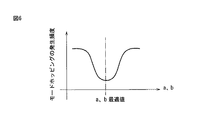
図5及び図6は、ビームモードの楕円化によってモードホッピングを抑制する例を説明する図である。例えば、図2のトーリック面形状において、断面A−A’上の曲率半径と断面B−B’上の曲率半径を各々最適化することにより、モードホッピングの発生頻度が最小(極小)となるように、ビームモード26の長軸方向の径a及び短軸方向の径bをそれぞれ最適化することができ、モードホッピングが発生しない又は抑制された共振器を構成することができる。このことは、図3の鞍型曲面形状、及び図4の円柱形状の折返しミラーを用いた場合も同様である。
5 and 6 are diagrams illustrating an example in which mode hopping is suppressed by beam mode ovalization. For example, in the toric surface shape of FIG. 2, the frequency of mode hopping is minimized (minimized) by optimizing the curvature radius on the section AA ′ and the curvature radius on the section BB ′. In addition, the major axis direction a and the minor axis direction b of the
さらに本発明では、図7aに示すように、折返しミラー18を設置した平面上で折返しミラーを回転させることができる。具体的には、折返しミラー18の反射面上の1つの点(好ましくは光軸12との交点)28を通りかつ、点28において折返しミラー18の反射面と垂直な直線30を回転軸として用いて折返しミラー18を回転させると、図5に示すように、ビームモード26を表す楕円の長軸・短軸の角度θを変化させることができる。
Furthermore, in the present invention, as shown in FIG. 7a, the folding mirror can be rotated on the plane where the
ここで、図8に示すように、モードホッピングの発生頻度が最小となる楕円の方向θは、発振器の使用時間によって変化する。例えば図8では、共振器の稼働時間がゼロ時間の場合(グラフ32)及び1000時間の場合(グラフ34)を示しており、モードホッピングの発生頻度は、グラフ32では楕円の向きθがθaのときに最小となり、グラフ34では楕円の向きθがθbのときに最小となる。そこで、折返しミラー18を回転させ、ビームモードの楕円の方向を稼働時間に応じて変化させることにより、モードホッピングの発生を長期間にわたって適切に抑制することができる。
Here, as shown in FIG. 8, the direction θ of the ellipse at which the frequency of mode hopping is minimized varies depending on the usage time of the oscillator. For example, FIG. 8 shows the case where the operation time of the resonator is zero hours (graph 32) and 1000 hours (graph 34), and the frequency of mode hopping is shown in
なお、折返しミラー18の回転は、折返しミラー18の周辺に設けたアクチュエータ等の回転機構を用いて自動で行ってもよいし、作業者が手動で行ってもよい。例えば、図7bに示すように、折返しミラー18を保持するミラー保持部19に、動力伝達部21を介してアクチュエータ23を接続し、アクチュエータ23を作動させることにより、折返しミラー18を回転軸30回りに自動で回転させることができる。
The rotation of the
また、図7c〜図7eに例示するように、折返しミラー18を回転させて角度を調整した後に、折返しミラー18の回転角度を固定できるロック機構を設けることが好ましい。ロック機構等の使用により、折返しミラー18の回転角度位置を長期間にわたり高精度に維持することができる。
Further, as illustrated in FIGS. 7c to 7e, it is preferable to provide a lock mechanism that can fix the rotation angle of the
なお折返しミラー18は、その回転角度位置をロックした後に再度、回転させて角度を調整することもあるために、上記ロック機構は簡単に解除できる機構であることが好ましい。具体的には、図7cに示すように、回転機構を構成する部品(ここではミラー保持部19)の側面近傍にリング状のネジ保持部25を設け、ネジ保持部25からミラー保持部19の側面に向けて固定用ネジ27を締め込むことにより、調整された折返しミラーの角度を保持するロック機構が挙げられる。或いは、図7dに示すように、回転軸30に垂直な部品(ここではミラー保持部19のフランジ部)を開閉式のトグルクランプ29で固定するロック機構や、図7eに示すように、該フランジ部の外周部近傍に設けられ、該フランジ部を挟持して固定する一対のロック機構(ブレーキ機構)31等が挙げられる。これらのロック機構はいずれも、容易に解除できる機構である。
Since the turning
(第2実施例)
第2実施例は、折返しミラーの曲率半径に関する。図2〜4で示したような、方向毎に曲率半径の異なるミラーについて、モードホッピングを抑制する効果は、断面A−A’のように、凹面形状でかつ曲率半径が最小となる断面での曲率半径(以後、凹面最小曲率半径と略記)と関連がある。具体的には、折返しミラー18の凹面最小曲率半径が小さいほど、モードホッピングが発生する確率は低下する。一方、凹面最小曲率半径が100mより小さくなると、発振するビームモードの真円度が低下し、金属切断時の加工性能(切断速度、切断面面粗度等、切断面の外観等)が、加工ワークの縦方向と横方向とで異なるという不具合が生じる。こうした不具合を防ぐため、凹面最小曲率半径は、200m〜700mの範囲であることが好ましい。
(Second embodiment)
The second embodiment relates to the radius of curvature of the folding mirror. As shown in FIGS. 2 to 4, the effect of suppressing mode hopping on the mirrors having different radii of curvature for each direction is as shown in the cross-section AA ′ in a cross-section having a concave shape and a minimum curvature radius. This is related to the radius of curvature (hereinafter abbreviated as the concave minimum curvature radius). Specifically, the smaller the concave curvature radius of the
第2実施例では、凹面最小曲率半径がこの範囲内であれば、モードホッピングの発生頻度を抑えつつ、ビームモードの真円度を一定の範囲内に維持することができ、加工性能(切断速度、切断面粗度、切断面の外観等)が被加工物の縦方向と横方向とで異なる等の不具合を抑制することができる。 In the second embodiment, if the concave radius of curvature is within this range, the roundness of the beam mode can be maintained within a certain range while suppressing the frequency of mode hopping, and the machining performance (cutting speed) can be maintained. , Cutting surface roughness, appearance of the cutting surface, etc.) can be suppressed.
(第3実施例)
図9〜図11は、本発明の第3実施例を説明する図である。図9に示すように、光共振器22は少なくとも2つの鞍型形状の折り返しミラー18a及び18bを有し、折り返しミラー18a及び18bの少なくとも一方は、図7aに示した折返しミラー18のように回転可能に構成されている。また図10は、レーザ光の中心と折返しミラー18aとの交点36において、折返しミラー18aに接する接平面38を表しており、図11は、レーザ光の中心と折返しミラー18bとの交点40において、折返しミラー18bに接する接平面42を表している。なお第3実施例において、図示された構成要素以外の構成要素については第1実施例と同様でよいので、詳細な説明は省略する。
(Third embodiment)
9 to 11 are diagrams for explaining a third embodiment of the present invention. As shown in FIG. 9, the
第3実施例では、光共振器22における(ここでは第1の折返しミラー18aに向かう)レーザ光の進行方向をZ軸とし、このZ軸に対して右手系をなすようX軸及びY軸(X−Y平面44)を定義したとき、定義されたX軸及びY軸を、図10に示すように接平面38上に転写し、さらに、図11に示すように接平面42上に転写する。
In the third embodiment, the traveling direction of the laser light in the optical resonator 22 (in this case, toward the
また、図10に示すように、折返しミラー18aにおいて、反射面の断面が凹面となりかつ、トーリック面形状、鞍型曲面形状又は円柱形状の曲率半径が最小となる断面と接平面38との交線は、1点鎖線48で示される直線となり、図11に示すように、折返しミラー18bにおいて、反射面の断面が凹面となりかつ、トーリック面形状、鞍型曲面形状又は円柱形状の曲率半径が最小となる断面と接平面42との交線は、1点鎖線50で示される直線となる。ここで、接平面38において直線48とX軸とのなす角度θ1、及び接平面42において直線50とX軸とのなす角度θ2を求めた際、第3実施例においては両角度が2つの折返しミラー間で互いに等しくなる(θ1=θ2)ように、第1の折返しミラー18a及び第2の折返しミラー18bが配置・構成されている。なお図10では、X軸を基準(0°)とし、X軸からY軸に向かう方向をプラスの角度として定義する。この定義は、後述する図11、図13及び図14についても同様である。
Further, as shown in FIG. 10, in the
この場合、第1の折返しミラー18aの凹面最小曲率半径をR1、第2の折返しミラー18bの凹面最小曲率半径をR2とすると、2つの折返しミラーの効果を足し合わせた実効的な凹面最小曲率半径Rは、以下の式(1)で表される。
In this case, assuming that the concave concave minimum radius of curvature of the
1/R=1/R1+1/R2 (1) 1 / R = 1 / R 1 + 1 / R 2 (1)
式(1)を用いて実効的な凹面最小曲率半径を計算すると、必ずR<R1、かつR<R2となる。従って第3実施例では、第2実施例と同様、凹面最小曲率半径が小さくなるので、ビームモードの楕円傾向を強めて、効率よくモードホッピングを抑制することができる。そして、折返しミラーを回転させて、ビームモードの楕円の方向を変化させることにより、モードホッピングの発生を長期間にわたって抑制することができる。 When an effective concave minimum radius of curvature is calculated using Equation (1), R <R 1 and R <R 2 are always satisfied. Accordingly, in the third embodiment, as in the second embodiment, since the concave minimum curvature radius becomes small, the elliptical tendency of the beam mode can be strengthened and mode hopping can be efficiently suppressed. Then, by rotating the folding mirror to change the direction of the ellipse in the beam mode, the occurrence of mode hopping can be suppressed over a long period of time.
(第4実施例)
第2実施例で示した、各折返しミラーの曲率半径の範囲を定める以外に、ビームモードを真円に近い形状にする第4実施例を、図12〜図14を参照しつつ説明する。図12に示すように、光共振器22は少なくとも2つの鞍型形状の折り返しミラー18c及び18dを有し、折り返しミラー18c及び18dの少なくとも一方は、図7aに示した折返しミラー18のように回転可能に構成されている。また図13は、レーザ光の中心と折返しミラー18cとの交点52において、折返しミラー18cに接する接平面54を表しており、図14は、レーザ光の中心と折返しミラー18dとの交点56において、折返しミラー18dに接する接平面58を表している。なお第4実施例において、図示された構成要素以外の構成要素については第1実施例と同様でよいので、詳細な説明は省略する。
(Fourth embodiment)
In addition to defining the range of the radius of curvature of each folding mirror shown in the second embodiment, a fourth embodiment in which the beam mode is a shape close to a perfect circle will be described with reference to FIGS. As shown in FIG. 12, the
光共振器22における(ここでは第1の折返しミラー18cに向かう)レーザ光の進行方向をZ軸とし、このZ軸に対して右手系をなすようX軸及びY軸(X−Y平面60)を定義したとき、定義されたX軸及びY軸を、図13に示すように接平面54上に転写し、さらに、図14に示すように接平面58上に転写する。
The traveling direction of the laser light in the optical resonator 22 (toward the
また、図13に示すように、折返しミラー18cにおいて、反射面の断面が凹面となりかつ、トーリック面形状、鞍型曲面形状又は円柱形状の曲率半径が最小となる断面と接平面54との交線は、1点鎖線64で示される直線となり、図14に示すように、折返しミラー18dにおいて、反射面の断面が凹面となりかつ、トーリック面形状、鞍型曲面形状又は円柱形状の曲率半径が最小となる断面と接平面58との交線は、1点鎖線66で示される直線となる。ここで、接平面54において直線64とX軸とのなす角度θ1、及び接平面58において直線66とX軸とのなす角度θ2を求めた際、第4実施例においては両角度差が2つの折返しミラー間で90°(θ2=θ1−90°)となるような第1の折返しミラー18a及び第2の折返しミラー18bの組み合わせを、少なくとも1組構成できるようになっている。
Further, as shown in FIG. 13, in the
第4実施例では、第3実施例とは異なり、第2の折返しミラー18dの凸面側の曲率半径が、モードホッピングの発生頻度に対し影響を与える。断面が凸面となり、かつ曲率半径が最小となる断面での曲率半径(以後、凸面最小曲率半径と略記)をr2とする。第1の折返しミラー18cについては、第3実施例と同様、凹面最小曲率R1が2つの折返しミラーの効果を足し合わせた実行的な凹面最小曲率半径Rに寄与する。この場合、Rは以下の式(2)で表される。
In the fourth embodiment, unlike the third embodiment, the curvature radius of the convex surface side of the
1/R=1/R1−1/r2 (2) 1 / R = 1 / R 1 −1 / r 2 (2)
式(2)を用いて実効的な凹面最小曲率半径を計算すると、必ずR>R1となる。従って第4実施例では、ビームモードを真円に近付けることができ、加工性能(切断速度、切断面粗度、切断面の外観等)が被加工物の縦方向と横方向とで異なる等の不具合を抑制することができる。 When an effective concave minimum curvature radius is calculated using Equation (2), R> R 1 is always satisfied. Therefore, in the fourth embodiment, the beam mode can be made close to a perfect circle, and the processing performance (cutting speed, cutting surface roughness, cutting surface appearance, etc.) is different in the vertical and horizontal directions of the workpiece. Problems can be suppressed.
なお上述の第1〜第4の実施例は、適宜組み合わせて使用することも可能である。例えば、第2実施例で説明したような曲率半径を有する折返しミラーを、第3又は第4実施例の折返しミラーに使用することが可能である。 The first to fourth embodiments described above can be used in appropriate combination. For example, a folding mirror having a radius of curvature as described in the second embodiment can be used for the folding mirror of the third or fourth embodiment.
10 ガスレーザ発振器
12 光軸
14 出力鏡
16 リア鏡
18、18a−18d 折返しミラー
19 ミラー保持部
20 放電管
22 光共振器
23 アクチュエータ
24 アパーチャ
26 ビームモード
28 位置データ補正・補間部
30 回転軸
38、42、54、58 接平面
DESCRIPTION OF
Claims (4)
前記鞍型曲面形状の折返しミラーのうち少なくとも1つは、該折返しミラーによって楕円形状となったビームモードの楕円の方向を、前記レーザ発振器におけるモードホッピングを抑制する方向に変更するように、該折返しミラーの反射面上の1つの点を通りかつ、該1つの点において該折返しミラーの反射面と垂直な直線を回転軸として回転可能に構成されている、レーザ発振器。 A laser oscillator including an optical resonator including at least one saddle-shaped curved mirror between an output mirror and a rear mirror disposed on an optical axis,
At least one of the saddle-shaped curved folding mirrors is configured to change the direction of the ellipse of the beam mode that is elliptical by the folding mirror to a direction that suppresses mode hopping in the laser oscillator. A laser oscillator configured to be rotatable about a straight line passing through one point on the reflecting surface of the mirror and perpendicular to the reflecting surface of the folding mirror at the one point.
前記光共振器におけるレーザ光の進行方向をZ軸とし、前記Z軸に対して右手系をなすようにX軸及びY軸を定義し、レーザ光の中心と前記折返しミラーの各々との交点において前記折返しミラーの各々に接する接平面に、前記X軸及びY軸を転写し、前記折返しミラーの各々において、前記折返しミラーの反射面が凹面となる断面でかつ、前記鞍型曲面形状の曲率半径が最小となる断面と前記接平面との交線が、前記接平面に転写された前記X軸に対してなす角度が、前記少なくとも2つの折返しミラー間で互いに等しくなるように、前記少なくとも2つの折返しミラーが配置されている、請求項1又は2に記載のレーザ発振器。 The optical resonator has at least two folding mirrors having the saddle-shaped curved surface shape ,
The traveling direction of the laser beam in the optical resonator is defined as the Z axis, the X axis and the Y axis are defined so as to form a right-handed system with respect to the Z axis, and at the intersection of the center of the laser beam and each of the folding mirrors The X-axis and the Y-axis are transferred to a tangential plane in contact with each of the folding mirrors, and each of the folding mirrors has a cross-section in which the reflecting surface of the folding mirror is a concave surface, and the curvature radius of the saddle-shaped curved surface shape The at least two folding mirrors so that an angle formed by an intersecting line between the cross-section having the minimum and the tangent plane with respect to the X axis transferred to the tangential plane is equal to each other between the at least two folding mirrors. The laser oscillator according to claim 1, wherein a folding mirror is disposed.
前記光共振器におけるレーザ光の進行方向をZ軸とし、前記Z軸に対して右手系をなすようにX軸及びY軸を定義し、レーザ光の中心と前記折返しミラーの各々との交点において前記折返しミラーの各々に接する接平面に、前記X軸及びY軸を転写し、前記折返しミラーの各々において、前記折返しミラーの反射面が凹面となる断面でかつ、前記鞍型曲面形状の曲率半径が最小となる断面と前記接平面との交線が、前記接平面に転写された前記X軸に対してなす角度が、前記少なくとも2つの折返しミラー間で、その差が90°となるように、前記少なくとも2つの折返しミラーが配置されている、請求項1又は2に記載のレーザ発振器。 The optical resonator has at least two folding mirrors having the saddle-shaped curved surface shape ,
The traveling direction of the laser beam in the optical resonator is defined as the Z axis, the X axis and the Y axis are defined so as to form a right-handed system with respect to the Z axis, and at the intersection of the center of the laser beam and each of the folding mirrors The X-axis and the Y-axis are transferred to a tangential plane in contact with each of the folding mirrors, and each of the folding mirrors has a cross-section in which the reflecting surface of the folding mirror is a concave surface, and the curvature radius of the saddle-shaped curved surface shape The angle formed by the line of intersection between the cross-section with the minimum and the tangent plane with respect to the X axis transferred to the tangential plane is 90 ° between the at least two folding mirrors. The laser oscillator according to claim 1, wherein the at least two folding mirrors are arranged.
Priority Applications (4)
| Application Number | Priority Date | Filing Date | Title |
|---|---|---|---|
| JP2015151687A JP6420216B2 (en) | 2015-07-31 | 2015-07-31 | Laser oscillator with folding mirror |
| DE102016008909.1A DE102016008909B4 (en) | 2015-07-31 | 2016-07-22 | Laser oscillator with folding mirror with a saddle surface shape |
| US15/216,818 US9787049B2 (en) | 2015-07-31 | 2016-07-22 | Laser oscillator having folding mirror |
| CN201610617248.1A CN106410584B (en) | 2015-07-31 | 2016-07-29 | Laser oscillator |
Applications Claiming Priority (1)
| Application Number | Priority Date | Filing Date | Title |
|---|---|---|---|
| JP2015151687A JP6420216B2 (en) | 2015-07-31 | 2015-07-31 | Laser oscillator with folding mirror |
Publications (2)
| Publication Number | Publication Date |
|---|---|
| JP2017034055A JP2017034055A (en) | 2017-02-09 |
| JP6420216B2 true JP6420216B2 (en) | 2018-11-07 |
Family
ID=57795866
Family Applications (1)
| Application Number | Title | Priority Date | Filing Date |
|---|---|---|---|
| JP2015151687A Active JP6420216B2 (en) | 2015-07-31 | 2015-07-31 | Laser oscillator with folding mirror |
Country Status (4)
| Country | Link |
|---|---|
| US (1) | US9787049B2 (en) |
| JP (1) | JP6420216B2 (en) |
| CN (1) | CN106410584B (en) |
| DE (1) | DE102016008909B4 (en) |
Families Citing this family (3)
| Publication number | Priority date | Publication date | Assignee | Title |
|---|---|---|---|---|
| JP7076914B2 (en) * | 2018-12-17 | 2022-05-30 | 住友重機械工業株式会社 | Folded optical resonator |
| JP7262217B2 (en) * | 2018-12-17 | 2023-04-21 | 住友重機械工業株式会社 | optical resonator |
| JP2022014651A (en) * | 2020-07-07 | 2022-01-20 | 住友重機械工業株式会社 | Beam forming optical device and circularity adjustment method |
Family Cites Families (25)
| Publication number | Priority date | Publication date | Assignee | Title |
|---|---|---|---|---|
| JPH0196629A (en) * | 1987-10-08 | 1989-04-14 | Fuji Photo Film Co Ltd | Light wavelength conversion module |
| JP2514680B2 (en) * | 1988-01-08 | 1996-07-10 | ファナック株式会社 | Laser oscillator |
| JPH02122586A (en) * | 1988-10-31 | 1990-05-10 | Nec Corp | Solid state laser oscillator |
| US5023886A (en) | 1988-12-01 | 1991-06-11 | Coherent, Inc. | High power laser with focusing mirror sets |
| KR0128528B1 (en) * | 1994-03-22 | 1998-04-07 | 신재인 | Apparatus and method for precisely wavelength-tuning single longitudinal mode tunable laser beams by utiling wedge prism |
| CN1032946C (en) * | 1994-06-03 | 1996-10-02 | 中国科学院上海光学精密机械研究所 | Super ring-mode laser |
| JP2720811B2 (en) * | 1995-03-15 | 1998-03-04 | 住友電気工業株式会社 | Laser focusing method and apparatus |
| US5771252A (en) * | 1996-01-29 | 1998-06-23 | Sdl, Inc. | External cavity, continuously tunable wavelength source |
| DE29606494U1 (en) * | 1996-04-10 | 1997-05-07 | Sacher Joachim Dr | Tuner |
| JP2002190642A (en) * | 2000-12-21 | 2002-07-05 | Ando Electric Co Ltd | Variable wavelength light source |
| EP1202408B1 (en) * | 2001-06-01 | 2003-02-12 | Agilent Technologies, Inc. (a Delaware corporation) | Tuning a laser |
| US6970488B2 (en) * | 2002-10-16 | 2005-11-29 | Eastman Kodak Company | Tunable organic VCSEL system |
| JP4206814B2 (en) | 2003-05-13 | 2009-01-14 | 三菱電機株式会社 | Laser oscillator |
| JP2005294393A (en) * | 2004-03-31 | 2005-10-20 | Fanuc Ltd | Laser oscillator |
| US20060182156A1 (en) * | 2005-02-15 | 2006-08-17 | Geraint Owen | Tuning a laser |
| GB0724874D0 (en) * | 2007-12-20 | 2008-01-30 | Uws Ventures Ltd | Turntable laser |
| CN102340100B (en) * | 2010-07-22 | 2015-06-03 | 中国计量科学研究院 | Grating outer-cavity laser and quasi-synchronization tuning method thereof |
| JP5376908B2 (en) * | 2008-11-13 | 2013-12-25 | ギガフォトン株式会社 | Two-stage laser apparatus and adjustment method applied to two-stage laser apparatus |
| JP2011066300A (en) | 2009-09-18 | 2011-03-31 | Shimadzu Corp | Laser resonator |
| US8712246B2 (en) * | 2010-04-01 | 2014-04-29 | Lawrence Livermore National Security, Llc | RF/optical shared aperture for high availability wideband communication RF/FSO links |
| CN102157890B (en) * | 2011-03-21 | 2012-07-25 | 华中科技大学 | Polarization-insensitive space folding laser resonator |
| US20130314757A1 (en) * | 2012-05-22 | 2013-11-28 | Koh Young Technology Inc. | Wavelength-changeable laser apparatus and tuning method using the same |
| US9500855B2 (en) * | 2012-06-04 | 2016-11-22 | The Boeing Company | Modal corrector mirror with compliant actuation for optical aberrations |
| JP6283374B2 (en) * | 2013-01-16 | 2018-02-21 | マツクス−プランク−ゲゼルシヤフト ツール フエルデルング デル ヴイツセンシヤフテン エー フアウMAX−PLANCK−GESELLSCHAFT ZUR FOeRDERUNG DER WISSENSCHAFTEN E.V. | Enhanced resonator including aspherical mirrors |
| JP2013165300A (en) * | 2013-05-27 | 2013-08-22 | Gigaphoton Inc | Two-stage laser device and adjustment method applied to two-stage laser device |
-
2015
- 2015-07-31 JP JP2015151687A patent/JP6420216B2/en active Active
-
2016
- 2016-07-22 DE DE102016008909.1A patent/DE102016008909B4/en active Active
- 2016-07-22 US US15/216,818 patent/US9787049B2/en active Active
- 2016-07-29 CN CN201610617248.1A patent/CN106410584B/en active Active
Also Published As
| Publication number | Publication date |
|---|---|
| CN106410584A (en) | 2017-02-15 |
| DE102016008909B4 (en) | 2020-01-30 |
| CN106410584B (en) | 2019-12-17 |
| US20170033526A1 (en) | 2017-02-02 |
| US9787049B2 (en) | 2017-10-10 |
| JP2017034055A (en) | 2017-02-09 |
| DE102016008909A1 (en) | 2017-02-02 |
Similar Documents
| Publication | Publication Date | Title |
|---|---|---|
| JP6420216B2 (en) | Laser oscillator with folding mirror | |
| US20050220164A1 (en) | Laser oscillator | |
| US7773315B2 (en) | Laser optical device | |
| JP4563437B2 (en) | Quartz crystal unit consisting of a Y-cut plate rotated twice | |
| JP2720811B2 (en) | Laser focusing method and apparatus | |
| JP5868226B2 (en) | Galvano scanner | |
| JP5885173B2 (en) | Laser processing equipment | |
| AU2017355468B2 (en) | Beam director with improved optics | |
| JP4977736B2 (en) | Ring beam converter | |
| JP4960043B2 (en) | Laser processing method and laser processing apparatus | |
| JP2017199908A (en) | Pump light device, disk laser including the same, and method for pumping laser active medium | |
| JP2008298866A (en) | Imaging optical system | |
| KR102025275B1 (en) | Apparatus for processing laser apertures | |
| JPH0862492A (en) | Scanning lens system | |
| JP2013038204A (en) | Laser equipment | |
| JP2016157829A (en) | Laser beam damper and laser device including the same | |
| WO2022153979A1 (en) | Design method for mirror and astigmatism-control mirror having reflective surface that satisfies design formula in design method | |
| JP7270514B2 (en) | BEAM SHAPER, PROCESSING APPARATUS, AND PROCESSING METHOD | |
| WO2020174779A1 (en) | Laser device | |
| JP2597500B2 (en) | Laser device | |
| JPH0856027A (en) | Optical resonator of laser equipment | |
| JP2024027240A (en) | laser probe | |
| JP2002314175A (en) | Laser device | |
| JPS6022390A (en) | Control method for laser beam | |
| JP5143781B2 (en) | Oscillating gear unit |
Legal Events
| Date | Code | Title | Description |
|---|---|---|---|
| A975 | Report on accelerated examination |
Free format text: JAPANESE INTERMEDIATE CODE: A971005 Effective date: 20161115 |
|
| A977 | Report on retrieval |
Free format text: JAPANESE INTERMEDIATE CODE: A971007 Effective date: 20161117 |
|
| A131 | Notification of reasons for refusal |
Free format text: JAPANESE INTERMEDIATE CODE: A131 Effective date: 20161206 |
|
| A02 | Decision of refusal |
Free format text: JAPANESE INTERMEDIATE CODE: A02 Effective date: 20170307 |
|
| A521 | Written amendment |
Free format text: JAPANESE INTERMEDIATE CODE: A523 Effective date: 20180719 |
|
| A61 | First payment of annual fees (during grant procedure) |
Free format text: JAPANESE INTERMEDIATE CODE: A61 Effective date: 20181011 |
|
| R150 | Certificate of patent or registration of utility model |
Ref document number: 6420216 Country of ref document: JP Free format text: JAPANESE INTERMEDIATE CODE: R150 |