JP6417690B2 - Projector, display device, and projector control method - Google Patents

Projector, display device, and projector control method Download PDF

Info

Publication number
JP6417690B2
JP6417690B2 JP2014062266A JP2014062266A JP6417690B2 JP 6417690 B2 JP6417690 B2 JP 6417690B2 JP 2014062266 A JP2014062266 A JP 2014062266A JP 2014062266 A JP2014062266 A JP 2014062266A JP 6417690 B2 JP6417690 B2 JP 6417690B2
Authority
JP
Japan
Prior art keywords
calibration
image
unit
control unit
projection
Prior art date
Legal status (The legal status is an assumption and is not a legal conclusion. Google has not performed a legal analysis and makes no representation as to the accuracy of the status listed.)
Expired - Fee Related
Application number
JP2014062266A
Other languages
Japanese (ja)
Other versions
JP2015159524A (en
JP2015159524A5 (en
Inventor
ポラック,カロル,マルチン
健児 田中
健児 田中
久保田 真司
真司 久保田
Current Assignee (The listed assignees may be inaccurate. Google has not performed a legal analysis and makes no representation or warranty as to the accuracy of the list.)
Seiko Epson Corp
Original Assignee
Seiko Epson Corp
Priority date (The priority date is an assumption and is not a legal conclusion. Google has not performed a legal analysis and makes no representation as to the accuracy of the date listed.)
Filing date
Publication date
Application filed by Seiko Epson Corp filed Critical Seiko Epson Corp
Priority to JP2014062266A priority Critical patent/JP6417690B2/en
Priority to US14/598,820 priority patent/US9992466B2/en
Publication of JP2015159524A publication Critical patent/JP2015159524A/en
Publication of JP2015159524A5 publication Critical patent/JP2015159524A5/ja
Application granted granted Critical
Publication of JP6417690B2 publication Critical patent/JP6417690B2/en
Expired - Fee Related legal-status Critical Current
Anticipated expiration legal-status Critical

Links

Images

Classifications

    • HELECTRICITY
    • H04ELECTRIC COMMUNICATION TECHNIQUE
    • H04NPICTORIAL COMMUNICATION, e.g. TELEVISION
    • H04N9/00Details of colour television systems
    • H04N9/12Picture reproducers
    • H04N9/31Projection devices for colour picture display, e.g. using electronic spatial light modulators [ESLM]
    • H04N9/3191Testing thereof
    • H04N9/3194Testing thereof including sensor feedback
    • HELECTRICITY
    • H04ELECTRIC COMMUNICATION TECHNIQUE
    • H04NPICTORIAL COMMUNICATION, e.g. TELEVISION
    • H04N9/00Details of colour television systems
    • H04N9/12Picture reproducers
    • H04N9/31Projection devices for colour picture display, e.g. using electronic spatial light modulators [ESLM]
    • H04N9/3179Video signal processing therefor
    • H04N9/3182Colour adjustment, e.g. white balance, shading or gamut
    • HELECTRICITY
    • H04ELECTRIC COMMUNICATION TECHNIQUE
    • H04NPICTORIAL COMMUNICATION, e.g. TELEVISION
    • H04N9/00Details of colour television systems
    • H04N9/12Picture reproducers
    • H04N9/31Projection devices for colour picture display, e.g. using electronic spatial light modulators [ESLM]
    • H04N9/3179Video signal processing therefor
    • H04N9/3185Geometric adjustment, e.g. keystone or convergence
    • HELECTRICITY
    • H04ELECTRIC COMMUNICATION TECHNIQUE
    • H04NPICTORIAL COMMUNICATION, e.g. TELEVISION
    • H04N9/00Details of colour television systems
    • H04N9/12Picture reproducers
    • H04N9/31Projection devices for colour picture display, e.g. using electronic spatial light modulators [ESLM]
    • H04N9/3179Video signal processing therefor
    • H04N9/3188Scale or resolution adjustment
    • HELECTRICITY
    • H04ELECTRIC COMMUNICATION TECHNIQUE
    • H04NPICTORIAL COMMUNICATION, e.g. TELEVISION
    • H04N17/00Diagnosis, testing or measuring for television systems or their details
    • H04N17/004Diagnosis, testing or measuring for television systems or their details for digital television systems

Landscapes

  • Engineering & Computer Science (AREA)
  • Multimedia (AREA)
  • Signal Processing (AREA)
  • Physics & Mathematics (AREA)
  • Geometry (AREA)
  • Projection Apparatus (AREA)
  • Transforming Electric Information Into Light Information (AREA)
  • Controls And Circuits For Display Device (AREA)
  • Health & Medical Sciences (AREA)
  • Biomedical Technology (AREA)
  • General Health & Medical Sciences (AREA)

Description

本発明は、プロジェクター、表示装置、及び、プロジェクターの制御方法に関する。   The present invention relates to a projector, a display device, and a projector control method.

従来、入力操作がされた場合に操作位置を検出する装置において、キャリブレーションを行うものが知られている(例えば、特許文献1参照)。例えば、特許文献1記載のシステムは、プロジェクターの投射画像を撮影し、撮影画像に基づき、投射画像と撮画像との間で位置を対応付けるキャリブレーションを実行する。 2. Description of the Related Art Conventionally, an apparatus that detects an operation position when an input operation is performed performs calibration (see, for example, Patent Document 1). For example, Patent Document 1 system according captures a projection image of the projector, on the basis of the photographic image, the calibration is performed for associating the position with the shadow image shooting and a projection image.

特開2011−227600号公報JP 2011-227600 A

特許文献1に記載のように、従来のオートキャリブレーションでは、市松模様(チェッカーパターン)等のパターンを含む画像を投射し、撮影画像からパターンを検出し、検出した位置で対応付けを行う。従って、パターンが細かいほど、多数の座標を対応付けることができ、位置検出の精度を高めることができる。しかしながら、パターンが細かいほど撮影画像からパターンを検出しにくくなってしまい、パターンを検出する処理の負荷が過大になるという問題があった。
本発明は、上述した事情に鑑みてなされたものであり、キャリブレーションによって、投射画像と撮画像との位置の対応づけを、効率よく高精度で行うことを目的とする。
As described in Patent Document 1, in the conventional auto-calibration, an image including a checkerboard pattern (checker pattern) or the like is projected, a pattern is detected from a captured image, and association is performed at the detected position. Therefore, the finer the pattern, the more coordinates can be associated, and the accuracy of position detection can be improved. However, there is a problem that the finer the pattern is, the more difficult it is to detect the pattern from the captured image, and the processing load for detecting the pattern becomes excessive.
The present invention has been made in view of the circumstances described above, the calibration, the correspondence between the positions of the shadow image shooting and the projection image, as intended for efficiently high accuracy.

上記目的を達成するために、本発明のプロジェクターは、投射面に画像を投射する投射部と、前記投射面を撮影した撮影画像に基づいて、前記投射面における操作を検出する検出部と、位置特定用のシンボルが配置されたキャリブレーション用画像に基づき前記投射部が投射する投射画像を撮影した撮影画像に基づいて、前記投射画像と前記撮画像との間で位置を対応付けるキャリブレーションを実行するキャリブレーション制御部と、を備え、前記キャリブレーション制御部は、前記シンボルの配置状態が異なる複数の前記キャリブレーション用画像に対応する前記撮影画像に基づき、前記キャリブレーションを実行すること、を特徴とする。
本発明によれば、シンボルの配置状態が異なる複数のキャリブレーション用画像を用いてキャリブレーションを実行するので、キャリブレーション用画像のシンボルが微細でなくても、撮影画像における位置と投射画像における位置とを、多数の位置で対応付けることができる。このため、位置の対応づけを高精度で行うことができる。また、キャリブレーション用画像のシンボルを微細にしなくて済むので、シンボルを確実に、容易に検出できる。従って、キャリブレーションを効率よく高精度で行うことができる。
In order to achieve the above object, a projector according to the present invention includes a projection unit that projects an image on a projection surface, a detection unit that detects an operation on the projection surface based on a captured image obtained by photographing the projection surface, and a position. based on the captured image obtained by photographing the projection image in which the projecting portion on the basis of the calibration image symbols for a particular is arranged to project, performs calibration associating the position between said shooting image and the projection image A calibration control unit that performs the calibration based on the captured images corresponding to the plurality of calibration images having different symbol arrangement states. And
According to the present invention, since calibration is performed using a plurality of calibration images having different symbol arrangement states, the position in the captured image and the position in the projection image can be obtained even if the calibration image symbol is not fine. Can be associated at a number of positions. For this reason, position matching can be performed with high accuracy. In addition, since it is not necessary to make the symbol of the calibration image minute, the symbol can be reliably and easily detected. Therefore, calibration can be performed efficiently and with high accuracy.

また、本発明は、上記プロジェクターにおいて、前記キャリブレーション制御部は、前記投射画像における位置と前記撮影画像における位置とを対応付けるキャリブレーションデータを生成すること、を特徴とする。
本発明によれば、投射画像と撮影画像の位置を細かく対応付けるキャリブレーションデータが生成されるので、このキャリブレーションデータを利用して、高精度で位置検出を行うことができる。
In the projector according to the aspect of the invention, the calibration control unit may generate calibration data that associates a position in the projection image with a position in the captured image.
According to the present invention, calibration data that finely associates the positions of the projected image and the photographed image is generated. Therefore, position detection can be performed with high accuracy using this calibration data.

また、本発明は、上記プロジェクターにおいて、前記キャリブレーション制御部は、複数の前記キャリブレーション用画像に対応する前記撮影画像に基づき、1の前記キャリブレーションデータを生成すること、を特徴とする。
本発明によれば、1つのキャリブレーション用画像を用いる場合に比べ、投射画像と撮影画像の位置を細かく対応付けるキャリブレーションデータを生成できる。
In the projector according to the aspect of the invention, the calibration control unit may generate one piece of calibration data based on the captured images corresponding to the plurality of calibration images.
According to the present invention, it is possible to generate calibration data that finely associates the positions of the projected image and the captured image as compared with the case of using one calibration image.

また、本発明は、上記プロジェクターにおいて、前記キャリブレーション制御部は、複数の前記キャリブレーション用画像に配置されるシンボルをそれぞれ異なる座標に対応付けて前記キャリブレーションデータを生成すること、を特徴とする。
本発明によれば、複数のキャリブレーション画像を用いることにより、1つのキャリブレーション画像のシンボルの数よりも多数の座標の対応づけを行うことができる。これにより、キャリブレーションデータにおいて多数の座標で位置を対応付けることができ、キャリブレーション用画像におけるシンボルの数に制限されず、高精細のキャリブレーションデータを生成できる。
In the projector according to the aspect of the invention, the calibration control unit may generate the calibration data by associating symbols arranged in the plurality of calibration images with different coordinates. .
According to the present invention, by using a plurality of calibration images, it is possible to associate more coordinates than the number of symbols of one calibration image. Thus, positions can be associated with a large number of coordinates in the calibration data, and high-definition calibration data can be generated without being limited by the number of symbols in the calibration image.

また、本発明は、上記プロジェクターにおいて、前記キャリブレーション制御部は、二値またはグレースケールの前記撮影画像に基づき前記キャリブレーションデータを生成すること、を特徴とする。
本発明によれば、撮影画像のデータ量を抑制することができ、撮影画像からシンボルを検出する処理の負荷が軽いため、効率よくキャリブレーションを実行できる。また、二値またはグレースケールの撮影画像においてシンボルを検出しやすいように、キャリブレーション用画像におけるシンボルを少なくしても、高精細のキャリブレーションデータを生成できる。
In the projector according to the aspect of the invention, the calibration control unit may generate the calibration data based on the binary or grayscale photographed image.
According to the present invention, the amount of data of a captured image can be suppressed, and the processing load for detecting a symbol from the captured image is light, so that calibration can be executed efficiently. In addition, high-definition calibration data can be generated even if the number of symbols in the calibration image is reduced so that the symbols can be easily detected in the binary or grayscale photographed image.

また、本発明は、上記プロジェクターにおいて、前記キャリブレーション制御部は、可視光により撮影された前記撮影画像に基づき前記キャリブレーションデータを生成すること、を特徴とする。
本発明によれば、キャリブレーション用画像に基づき可視光で画像が投射され、この投射画像を可視光で撮影した撮影画像に基づいてキャリブレーションが行われる。このため、自動的に実行されるキャリブレーションの様子をユーザーが視認できる。
In the projector according to the aspect of the invention, the calibration control unit may generate the calibration data based on the captured image captured with visible light.
According to the present invention, an image is projected with visible light based on a calibration image, and calibration is performed based on a captured image obtained by capturing the projected image with visible light. For this reason, the user can visually recognize the state of the calibration that is automatically executed.

また、本発明は、上記プロジェクターにおいて、前記キャリブレーション用画像は、少なくとも複数の画素で構成される前記シンボルが配置された画像であること、を特徴とする。
本発明によれば、キャリブレーション用画像に配置されるシンボルが複数の画素で構成され、面積を有するので、撮影画像からシンボルを容易に検出できる。また、シンボルの形状の変形等から、撮影画像と投射画像とを対応づける処理において、より多くの情報を得ることができる。さらに、例えば撮影画像からシンボルの像を抽出して、シンボルの重心を検出座標とすることにより、高精度でキャリブレーションを行うことができる。
In the projector according to the aspect of the invention, the calibration image may be an image in which the symbols including at least a plurality of pixels are arranged.
According to the present invention, since the symbol arranged in the calibration image is composed of a plurality of pixels and has an area, the symbol can be easily detected from the captured image. Further, more information can be obtained in the process of associating the captured image with the projected image from the deformation of the symbol shape or the like. Furthermore, for example, by extracting a symbol image from a photographed image and using the center of gravity of the symbol as a detection coordinate, calibration can be performed with high accuracy.

また、上記目的を達成するために、本発明の表示装置は、表示面に画像を表示する表示部と、前記表示面を撮影した撮影画像に基づいて、前記表示面における操作を検出する検出部と、位置特定用のシンボルが配置されたキャリブレーション用画像に基づき前記表示部が表示する表示画像を撮影した撮影画像に基づいて、前記表示画像と前記撮画像との間で位置を対応付けるキャリブレーションを実行するキャリブレーション制御部と、を備え、前記キャリブレーション制御部は、前記シンボルの配置状態が異なる複数の前記キャリブレーション用画像に対応する前記撮影画像に基づき、前記キャリブレーションを実行すること、を特徴とする。
本発明によれば、シンボルの配置状態が異なる複数のキャリブレーション用画像を用いてキャリブレーションを実行するので、キャリブレーション用画像のシンボルが微細でなくても、撮影画像における位置と投射画像における位置とを、多数の位置で対応付けることができる。このため、位置の対応づけを高精度で行うことができる。また、キャリブレーション用画像のシンボルを微細にしなくて済むので、シンボルを確実に、容易に検出できる。従って、キャリブレーションを効率よく高精度で行うことができる。
In order to achieve the above object, a display device according to the present invention includes a display unit that displays an image on a display surface, and a detection unit that detects an operation on the display surface based on a captured image obtained by capturing the display surface. If, on the basis of the photographic image which the display unit based on the calibration image symbols for localization is arranged have taken a display image to be displayed, associating the position between said shooting image and the display image calibration A calibration control unit that executes calibration, and the calibration control unit performs the calibration based on the captured images corresponding to the plurality of calibration images having different arrangement states of the symbols. It is characterized by.
According to the present invention, since calibration is performed using a plurality of calibration images having different symbol arrangement states, the position in the captured image and the position in the projection image can be obtained even if the calibration image symbol is not fine. Can be associated at a number of positions. For this reason, position matching can be performed with high accuracy. In addition, since it is not necessary to make the symbol of the calibration image minute, the symbol can be reliably and easily detected. Therefore, calibration can be performed efficiently and with high accuracy.

また、上記目的を達成するために、本発明は、投射面に画像を投射する投射部を備えたプロジェクターの制御方法であって、前記投射面を撮影した撮影画像に基づいて、前記投射面における操作を検出し、位置特定用のシンボルが配置されたキャリブレーション用画像に基づき前記投射部が投射する投射画像を撮影した撮影画像に基づいて、前記投射画像と前記撮画像との間で位置を対応付けるキャリブレーションを実行し、前記キャリブレーションを、前記シンボルの配置状態が異なる複数の前記キャリブレーション用画像に対応する前記撮影画像に基づき実行すること、を特徴とする。
本発明によれば、シンボルの配置状態が異なる複数のキャリブレーション用画像を用いてキャリブレーションを実行するので、キャリブレーション用画像のシンボルが微細でなくても、撮影画像における位置と投射画像における位置とを、多数の位置で対応付けることができる。このため、位置の対応づけを高精度で行うことができる。また、キャリブレーション用画像のシンボルを微細にしなくて済むので、シンボルを確実に、容易に検出できる。従って、キャリブレーションを効率よく高精度で行うことができる。
In order to achieve the above object, the present invention provides a projector control method including a projection unit that projects an image on a projection surface, and based on a captured image obtained by photographing the projection surface, detecting an operation based on the captured images the projection unit based on a calibration image symbols for localization is arranged is photographed projected image to be projected, a position between said shooting image and the projection image Is performed, and the calibration is performed based on the captured images corresponding to the plurality of calibration images having different symbol arrangement states.
According to the present invention, since calibration is performed using a plurality of calibration images having different symbol arrangement states, the position in the captured image and the position in the projection image can be obtained even if the calibration image symbol is not fine. Can be associated at a number of positions. For this reason, position matching can be performed with high accuracy. In addition, since it is not necessary to make the symbol of the calibration image minute, the symbol can be reliably and easily detected. Therefore, calibration can be performed efficiently and with high accuracy.

本発明によれば、キャリブレーションを効率よく高精度で行うことができる。   According to the present invention, calibration can be performed efficiently and with high accuracy.

実施形態に係るプロジェクションシステムの概略構成図である。1 is a schematic configuration diagram of a projection system according to an embodiment. プロジェクションシステムの機能ブロック図である。It is a functional block diagram of a projection system. オートキャリブレーション画像の一例を示す図である。It is a figure which shows an example of an auto calibration image. スクリーンに投射されたオートキャリブレーション画像を撮影した撮影画像データの一例を示す図である。It is a figure which shows an example of the picked-up image data which image | photographed the auto calibration image projected on the screen. マニュアルキャリブレーション画像の一例を示す図である。It is a figure which shows an example of a manual calibration image. プロジェクターの動作を示すフローチャートである。It is a flowchart which shows operation | movement of a projector. プロジェクターの動作を示すフローチャートである。It is a flowchart which shows operation | movement of a projector. オートキャリブレーション画像の例を示す図である。It is a figure which shows the example of an auto calibration image.

以下、図面を参照して本発明の実施形態について説明する。
図1は、本発明を適用した実施形態に係るプロジェクションシステム1の構成を示す図である。プロジェクションシステム1は、スクリーンSC(投射面、操作面、表示面)の上方に設置されたプロジェクター10と、スクリーンSCの上部に設置された光出射装置60(光出射部)とを備える。
Hereinafter, embodiments of the present invention will be described with reference to the drawings.
FIG. 1 is a diagram showing a configuration of a projection system 1 according to an embodiment to which the present invention is applied. The projection system 1 includes a projector 10 installed above a screen SC (projection surface, operation surface, display surface), and a light emitting device 60 (light emitting unit) installed above the screen SC.

プロジェクター10はスクリーンSCの直上または斜め上方に設置され、斜め下方のスクリーンSCに向けて画像を投射する表示装置である。また、本実施形態で例示するスクリーンSCは、壁面に固定され、或いは床面に立設された、平板または幕である。本発明はこの例に限定されず、壁面をスクリーンSCとして使用することも可能である。この場合、スクリーンSCとして使用される壁面の上部にプロジェクター10及び光出射装置60を取り付けるとよい。   The projector 10 is a display device that is installed directly above or diagonally above the screen SC and projects an image toward the screen SC diagonally below. Further, the screen SC exemplified in the present embodiment is a flat plate or a curtain fixed to a wall surface or standing on a floor surface. The present invention is not limited to this example, and the wall surface can be used as the screen SC. In this case, the projector 10 and the light emitting device 60 may be attached to the upper part of the wall surface used as the screen SC.

プロジェクター10は、PC(パーソナルコンピューター)、ビデオ再生装置、DVD再生装置等の外部の画像供給装置に接続され、この画像供給装置から供給されるアナログ画像信号またはデジタル画像データに基づき、スクリーンSCに画像を投射する。また、プロジェクター10は、内蔵する記憶部110(図2)や外部接続される記憶媒体に記憶された画像データを読み出して、この画像データに基づきスクリーンSCに画像を表示する構成としてもよい。
光出射装置60は、固体光源からなる光源部61(図2)を有し、光源部61が発する光をスクリーンSCに沿って拡散させて出射(照射)する。光出射装置60の出射範囲を図1に角度θで示す。光出射装置60はスクリーンSCの上端より上に設置され、下向きに角度θの範囲に光を出射し、この光はスクリーンSCに沿う光の層を形成する。本実施形態では角度θはほぼ180度に達し、スクリーンSCのほぼ全体に、光の層が形成される。スクリーンSCの表面と光の層とは近接していることが好ましく、本実施形態では、スクリーンSCの表面と光の層との距離は概ね10mm〜1mmの範囲内である。
光出射装置60が出射する光は可視領域外の光であり、本実施形態では赤外光とする。
The projector 10 is connected to an external image supply device such as a PC (personal computer), a video reproduction device, a DVD reproduction device, and the like, and an image is displayed on the screen SC based on an analog image signal or digital image data supplied from the image supply device. Project. The projector 10 may be configured to read out image data stored in a built-in storage unit 110 (FIG. 2) or an externally connected storage medium and display an image on the screen SC based on the image data.
The light emitting device 60 has a light source unit 61 (FIG. 2) made of a solid light source, and diffuses (emits) light emitted from the light source unit 61 along the screen SC. The emission range of the light emitting device 60 is shown in FIG. The light emitting device 60 is installed above the upper end of the screen SC and emits light downward in the range of the angle θ, and this light forms a layer of light along the screen SC. In this embodiment, the angle θ reaches approximately 180 degrees, and a light layer is formed on almost the entire screen SC. The surface of the screen SC and the light layer are preferably close to each other. In this embodiment, the distance between the surface of the screen SC and the light layer is approximately in the range of 10 mm to 1 mm.
The light emitted from the light emitting device 60 is light outside the visible region, and is infrared light in this embodiment.

プロジェクションシステム1は、スクリーンSCに対する指示操作が行われた場合に、指示位置をプロジェクター10によって検出する。
指示操作に利用される指示体は、ペン型の指示体70を用いることができる。指示体70の先端部71は、押圧された場合に動作する操作スイッチ75(図2)を内蔵しているので、先端部71を壁やスクリーンSCに押しつける操作がされると操作スイッチ75がオンになる。指示体70は、ユーザーが棒状の軸部72を手に持って、先端部71をスクリーンSCに接触させるように操作され、先端部71をスクリーンSCに押しつける操作も行われる。先端部71には、光を発する送受信部74(図2)を備える。プロジェクター10は、指示体70が発する光に基づき、先端部71の位置を、指示位置として検出する。指示体70が発する光は可視領域外の光であり、本実施形態では赤外光とする。
The projection system 1 detects the indicated position by the projector 10 when an instruction operation is performed on the screen SC.
A pen-type indicator 70 can be used as the indicator used for the instruction operation. Since the distal end portion 71 of the indicator 70 incorporates an operation switch 75 (FIG. 2) that operates when pressed, the operation switch 75 is turned on when the distal end portion 71 is pressed against the wall or the screen SC. become. The indicator 70 is operated so that the user holds the rod-shaped shaft portion 72 in his / her hand and brings the tip portion 71 into contact with the screen SC, and an operation of pressing the tip portion 71 against the screen SC is also performed. The distal end portion 71 includes a transmission / reception unit 74 (FIG. 2) that emits light. The projector 10 detects the position of the distal end portion 71 as the indication position based on the light emitted from the indicator 70. The light emitted from the indicator 70 is light outside the visible region, and is infrared light in this embodiment.

また、ユーザーの手指である指示体80で位置指示操作を行う場合、ユーザーは指をスクリーンSCに接触させる。この場合、指示体80がスクリーンSCに接触した位置が検出される。
すなわち、指示体80の先端(例えば、指先)がスクリーンSCに接触するときに、光出射装置60が形成する光の層を遮る。このとき、光出射装置60が出射した光が指示体80に当たって反射し、反射光の一部は指示体80からプロジェクター10に向かって進む。プロジェクター10は、スクリーンSC側からの光、すなわち下方からの光を後述する位置検出部50により検出する機能を有するので、指示体80の反射光を検出できる。プロジェクター10は、指示体80で反射した反射光を検出することにより、指示体80によるスクリーンSCへの指示操作を検出する。また、プロジェクター10は指示体80により指示された指示位置を検出する。
光出射装置60が出射する光の層はスクリーンSCに近接しているので、指示体80において光が反射する位置は、スクリーンSCに最も近い先端、或いは指示位置と見なすことができる。このため、指示体80の反射光に基づき指示位置を特定できる。
Further, when a position indicating operation is performed with the indicator 80 that is a user's finger, the user brings the finger into contact with the screen SC. In this case, the position where the indicator 80 contacts the screen SC is detected.
That is, when the tip (for example, fingertip) of the indicator 80 contacts the screen SC, the light layer formed by the light emitting device 60 is blocked. At this time, the light emitted from the light emitting device 60 strikes and reflects the indicator 80, and part of the reflected light travels from the indicator 80 toward the projector 10. Since the projector 10 has a function of detecting light from the screen SC side, that is, light from below by the position detection unit 50 described later, the reflected light of the indicator 80 can be detected. The projector 10 detects an instruction operation on the screen SC by the indicator 80 by detecting the reflected light reflected by the indicator 80. Further, the projector 10 detects the indicated position indicated by the indicator 80.
Since the light layer emitted from the light emitting device 60 is close to the screen SC, the position where the light is reflected by the indicator 80 can be regarded as the tip closest to the screen SC or the indication position. For this reason, the indicated position can be specified based on the reflected light of the indicator 80.

プロジェクションシステム1は、インタラクティブホワイトボードシステムとして機能し、ユーザーが指示体70、80により行った指示操作を検出して、指示位置を投射画像に反映させる。
具体的には、プロジェクションシステム1は、指示位置に図形を描画したり文字や記号を配置したりする処理、指示位置の軌跡に沿って図形を描画する処理、描画した図形や配置した文字または記号を消去する処理等を行う。また、スクリーンSCに描画された図形、配置された文字または記号を画像データとして保存することもでき、外部の装置に出力することもできる。
さらに、指示位置を検出することによりポインティングデバイスとして動作し、スクリーンSCにプロジェクター10が画像を投射する画像投射領域における指示位置の座標を出力してもよい。また、この座標を用いてGUI(Graphical User Interface)操作を行ってもよい。
The projection system 1 functions as an interactive whiteboard system, detects an instruction operation performed by the user using the indicators 70 and 80, and reflects the indicated position on the projection image.
Specifically, the projection system 1 performs a process of drawing a graphic or placing a character or a symbol at a designated position, a process of drawing a graphic along the locus of the designated position, a drawn figure, a placed character or symbol The process etc. which erase is performed. In addition, graphics drawn on the screen SC, arranged characters or symbols can be stored as image data, and can be output to an external device.
Further, it may operate as a pointing device by detecting the designated position, and output the coordinates of the designated position in the image projection area where the projector 10 projects an image on the screen SC. Further, a GUI (Graphical User Interface) operation may be performed using these coordinates.

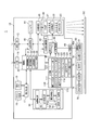
図2は、プロジェクションシステム1を構成する各部の機能ブロック図である。
プロジェクター10は、外部の装置に接続されるインターフェイスとして、I/F(インターフェイス)部11及び画像I/F(インターフェイス)部12を備える。I/F部11及び画像I/F部12は有線接続用のコネクターを備え、上記コネクターに対応するインターフェイス回路を備えていてもよい。また、I/F部11及び画像I/F部12は、無線通信インターフェイスを備えていてもよい。有線接続用のコネクター及びインターフェイス回路としては有線LAN、IEEE1394、USB等に準拠したものが挙げられる。また、無線通信インターフェイスとしては無線LANやBluetooth(登録商標)等に準拠したものが挙げられる。画像I/F部12には、HDMI(登録商標)インターフェイス等の画像データ用のインターフェイスを用いることもできる。画像I/F部12は、音声データが入力されるインターフェイスを備えてもよい。
FIG. 2 is a functional block diagram of each part constituting the projection system 1.
The projector 10 includes an I / F (interface) unit 11 and an image I / F (interface) unit 12 as interfaces connected to external devices. The I / F unit 11 and the image I / F unit 12 may include a connector for wired connection, and may include an interface circuit corresponding to the connector. The I / F unit 11 and the image I / F unit 12 may include a wireless communication interface. Examples of the connector and interface circuit for wired connection include those based on wired LAN, IEEE 1394, USB, and the like. Examples of the wireless communication interface include those that comply with a wireless LAN, Bluetooth (registered trademark), or the like. The image I / F unit 12 may be an image data interface such as an HDMI (registered trademark) interface. The image I / F unit 12 may include an interface through which audio data is input.

I/F部11は、PC等の外部の装置との間で各種データを送受信するインターフェイスである。I/F部11は、画像の投射に関する制御データ、プロジェクター10の動作を設定する設定データ、プロジェクター10が検出した指示位置の座標データ等を入出力する。後述する制御部30は、I/F部11を介して外部の装置とデータを送受信する機能を有する。
画像I/F部12は、デジタル画像データが入力されるインターフェイスである。本実施形態のプロジェクター10は、画像I/F部12を介して入力されるデジタル画像データに基づき画像を投射する。なお、プロジェクター10は、アナログ画像信号に基づき画像を投射する機能を備えてもよく、この場合、画像I/F部12は、アナログ画像用のインターフェイスと、アナログ画像信号をデジタル画像データに変換するA/D変換回路とを備えてもよい。
The I / F unit 11 is an interface that transmits and receives various data to and from an external device such as a PC. The I / F unit 11 inputs and outputs control data related to image projection, setting data for setting the operation of the projector 10, coordinate data of the designated position detected by the projector 10, and the like. The control unit 30 described later has a function of transmitting / receiving data to / from an external device via the I / F unit 11.
The image I / F unit 12 is an interface through which digital image data is input. The projector 10 of the present embodiment projects an image based on digital image data input via the image I / F unit 12. The projector 10 may have a function of projecting an image based on the analog image signal. In this case, the image I / F unit 12 converts the analog image signal into digital image data and an analog image interface. And an A / D conversion circuit.

プロジェクター10は、光学的な画像の形成を行う投射部20(表示部)を備える。投射部20は、光源部21、光変調装置22、および投射光学系23を有する。光源部21は、キセノンランプ、超高圧水銀ランプ、LED(Light Emitting Diode)、或いはレーザー光源等からなる光源を備える。また、光源部21は、光源が発した光を光変調装置22に導くリフレクターおよび補助リフレクターを備えていてもよい。さらに、投射光の光学特性を高めるためのレンズ群(図示略)、偏光板、或いは光源が発した光の光量を光変調装置22に至る経路上で低減させる調光素子等を備えていてもよい。
光変調装置22は、例えばRGBの三原色に対応した3枚の透過型液晶パネルを備え、この液晶パネルを透過する光を変調して画像光を生成する。光源部21からの光はRGBの3色の色光に分離され、各色光は対応する各液晶パネルに入射する。各液晶パネルを通過して変調された色光はクロスダイクロイックプリズム等の合成光学系によって合成され、投射光学系23に射出される。
The projector 10 includes a projection unit 20 (display unit) that forms an optical image. The projection unit 20 includes a light source unit 21, a light modulation device 22, and a projection optical system 23. The light source unit 21 includes a light source including a xenon lamp, an ultra high pressure mercury lamp, an LED (Light Emitting Diode), a laser light source, or the like. The light source unit 21 may include a reflector and an auxiliary reflector that guide light emitted from the light source to the light modulation device 22. Further, a lens group (not shown) for enhancing the optical characteristics of the projection light, a polarizing plate, or a dimming element that reduces the amount of light emitted from the light source on the path to the light modulation device 22 may be provided. Good.
The light modulation device 22 includes, for example, three transmissive liquid crystal panels corresponding to the three primary colors of RGB, and generates image light by modulating light transmitted through the liquid crystal panel. The light from the light source unit 21 is separated into three color lights of RGB, and each color light enters each corresponding liquid crystal panel. The color light modulated by passing through each liquid crystal panel is combined by a combining optical system such as a cross dichroic prism and emitted to the projection optical system 23.

投射光学系23は、光変調装置22により変調された画像光をスクリーンSC方向へ導き、スクリーンSC上に結像させるレンズ群を備える。また、投射光学系23は、スクリーンSCの投射画像の拡大・縮小および焦点の調整を行うズーム機構、フォーカスの調整を行うフォーカス調整機構を備えていてもよい。プロジェクター10が短焦点型である場合、投射光学系23に、画像光をスクリーンSCに向けて反射する凹面鏡を備えていてもよい。   The projection optical system 23 includes a lens group that guides the image light modulated by the light modulation device 22 toward the screen SC and forms an image on the screen SC. Further, the projection optical system 23 may include a zoom mechanism for enlarging / reducing the projected image on the screen SC and adjusting the focus, and a focus adjusting mechanism for adjusting the focus. When the projector 10 is a short focus type, the projection optical system 23 may include a concave mirror that reflects image light toward the screen SC.

投射部20には、制御部30の制御に従って光源部21を点灯させる光源駆動部45、及び、制御部30の制御に従って光変調装置22を動作させる光変調装置駆動部46が接続される。光源駆動部45は、光源部21の点灯/消灯の切り替えを行い、光源部21の光量を調整する機能を有していてもよい。   The projection unit 20 is connected to a light source drive unit 45 that turns on the light source unit 21 according to the control of the control unit 30 and a light modulation device drive unit 46 that operates the light modulation device 22 according to the control of the control unit 30. The light source drive unit 45 may have a function of switching on / off the light source unit 21 and adjusting the light amount of the light source unit 21.

プロジェクター10は、投射部20が投射する画像を処理する画像処理系を備える。この画像処理系は、プロジェクター10を制御する制御部30、記憶部110、操作検出部17、画像処理部40、光源駆動部45、及び光変調装置駆動部46を含む。また、画像処理部40にはフレームメモリー44が接続され、制御部30には姿勢センサー47、出射装置駆動部48、及び位置検出部50が接続される。これらの各部を画像処理系に含めてもよい。   The projector 10 includes an image processing system that processes an image projected by the projection unit 20. The image processing system includes a control unit 30 that controls the projector 10, a storage unit 110, an operation detection unit 17, an image processing unit 40, a light source driving unit 45, and a light modulation device driving unit 46. In addition, a frame memory 44 is connected to the image processing unit 40, and an attitude sensor 47, an emission device driving unit 48, and a position detection unit 50 are connected to the control unit 30. These units may be included in the image processing system.

制御部30は、所定の制御プログラム111を実行することにより、プロジェクター10の各部を制御する。記憶部110は、制御部30が実行する制御プログラム111、および、制御部30が処理するデータを不揮発的に記憶する。記憶部110は、プロジェクター10の動作を設定するための画面の設定画面データ112、及び、設定画面データ112を利用して設定された内容を示す設定データ113を記憶する。   The control unit 30 controls each unit of the projector 10 by executing a predetermined control program 111. The storage unit 110 stores the control program 111 executed by the control unit 30 and the data processed by the control unit 30 in a nonvolatile manner. The storage unit 110 stores setting screen data 112 of a screen for setting the operation of the projector 10 and setting data 113 indicating the contents set using the setting screen data 112.

画像処理部40は、制御部30の制御に従って、画像I/F部12を介して入力される画像データを処理し、光変調装置駆動部46に画像信号を出力する。画像処理部40が実行する処理は、3D(立体)画像と2D(平面)画像の判別処理、解像度変換処理、フレームレート変換処理、歪み補正処理、デジタルズーム処理、色調補正処理、輝度補正処理等である。画像処理部40は、制御部30により指定された処理を実行し、必要に応じて、制御部30から入力されるパラメーターを使用して処理を行う。また、上記のうち複数の処理を組み合わせて実行することも勿論可能である。
画像処理部40はフレームメモリー44に接続されている。画像処理部40は、画像入力I/F12から入力される画像データをフレームメモリー44に展開して、展開した画像データに対し上記の各種処理を実行する。画像処理部40は、処理後の画像データをフレームメモリー44から読み出して、この画像データに対応するR、G、Bの画像信号を生成し、光変調装置駆動部46に出力する。
光変調装置駆動部46は、光変調装置22の液晶パネルに接続される。光変調装置駆動部46は、画像処理部40から入力される画像信号に基づいて液晶パネルを駆動し、各液晶パネルに画像を描画する。
The image processing unit 40 processes the image data input via the image I / F unit 12 under the control of the control unit 30, and outputs an image signal to the light modulation device driving unit 46. The processing executed by the image processing unit 40 includes 3D (stereoscopic) image and 2D (planar) image discrimination processing, resolution conversion processing, frame rate conversion processing, distortion correction processing, digital zoom processing, color tone correction processing, luminance correction processing, and the like. is there. The image processing unit 40 executes processing designated by the control unit 30 and performs processing using parameters input from the control unit 30 as necessary. Of course, it is also possible to execute a combination of a plurality of processes.
The image processing unit 40 is connected to the frame memory 44. The image processing unit 40 expands the image data input from the image input I / F unit 12 in the frame memory 44, and executes the various processes described above on the expanded image data. The image processing unit 40 reads out the processed image data from the frame memory 44, generates R, G, B image signals corresponding to the image data, and outputs them to the light modulation device driving unit 46.
The light modulation device driving unit 46 is connected to the liquid crystal panel of the light modulation device 22. The light modulator driving unit 46 drives the liquid crystal panel based on the image signal input from the image processing unit 40 and draws an image on each liquid crystal panel.

操作検出部17は、入力デバイスとして機能するリモコン受光部18および操作パネル19に接続され、リモコン受光部18及び操作パネル19を介した操作を検出する。
リモコン受光部18は、プロジェクター10のユーザーが使用するリモコン(図示略)がボタン操作に対応して送信した赤外線信号を受光する。リモコン受光部18は、上記リモコンから受光した赤外線信号をデコードして、上記リモコンにおける操作内容を示す操作データを生成し、制御部30に出力する。
操作パネル19は、プロジェクター10の外装筐体に設けられ、各種スイッチおよびインジケーターランプを有する。操作検出部17は、制御部30の制御に従い、プロジェクター10の動作状態や設定状態に応じて操作パネル19のインジケーターランプを適宜点灯及び消灯させる。この操作パネル19のスイッチが操作されると、操作されたスイッチに対応する操作データが操作検出部17から制御部30に出力される。
The operation detection unit 17 is connected to the remote control light receiving unit 18 and the operation panel 19 that function as an input device, and detects an operation through the remote control light reception unit 18 and the operation panel 19.
Remote control receiver 18, a remote controller (not shown) that the user of the projector 10 is used to receive optical infrared signals transmitted in response to the button operation. The remote control light receiving unit 18 decodes the infrared signal received from the remote control, generates operation data indicating the operation content of the remote control, and outputs the operation data to the control unit 30.
The operation panel 19 is provided in the exterior housing of the projector 10 and has various switches and indicator lamps. The operation detection unit 17 appropriately turns on and off the indicator lamp of the operation panel 19 according to the operation state and setting state of the projector 10 according to the control of the control unit 30. When the switch of the operation panel 19 is operated, operation data corresponding to the operated switch is output from the operation detection unit 17 to the control unit 30.

出射装置駆動部48は、接続部49を介して光出射装置60に接続される。接続部49は、例えば複数のピンを有するコネクターであり、接続部49には光出射装置60がケーブル60aを介して接続される。出射装置駆動部48は、制御部30の制御に従ってパルス信号を生成し、接続部49を介して光出射装置60に出力する。また、出射装置駆動部48は接続部49を介して光出射装置60に電源を供給する。   The emission device driving unit 48 is connected to the light emission device 60 via the connection unit 49. The connection portion 49 is a connector having a plurality of pins, for example, and the light emitting device 60 is connected to the connection portion 49 via a cable 60a. The emission device driving unit 48 generates a pulse signal according to the control of the control unit 30 and outputs the pulse signal to the light emission device 60 via the connection unit 49. Further, the emission device driving unit 48 supplies power to the light emission device 60 through the connection unit 49.

光出射装置60は、図1に示すように略箱形のケースに、光源部61、及び光学部品を収容して構成される。本実施形態の光出射装置60は、光源部61に、赤外光を発する固体光源62を備える。固体光源62が発する赤外光は、平行化レンズ及びパウエルレンズによって拡散され、スクリーンSCに沿った面を形成する。また、光源部61が複数の固体光源を備え、これら複数の固体光源が発する光をそれぞれ拡散させることによって、スクリーンSCの画像投射範囲を覆うように光の層を形成してもよい。また、光出射装置60は、光源部61が発する光の層とスクリーンSCとの間の距離や角度を調整する調整機構を備えていてもよい。光出射装置60は、出射装置駆動部48から供給されるパルス信号および電源により、光源部61を点灯させる。光源部61が点灯及び消灯するタイミングは、出射装置駆動部48が制御する。制御部30は、出射装置駆動部48を制御して、後述する撮像部51が撮影を行うタイミングに同期して光源部61を点灯させる。   As shown in FIG. 1, the light emitting device 60 is configured by housing a light source unit 61 and optical components in a substantially box-shaped case. The light emitting device 60 of this embodiment includes a solid light source 62 that emits infrared light in a light source unit 61. The infrared light emitted from the solid light source 62 is diffused by the collimating lens and the Powell lens to form a surface along the screen SC. The light source unit 61 may include a plurality of solid light sources, and a light layer may be formed so as to cover the image projection range of the screen SC by diffusing light emitted from the plurality of solid light sources. The light emitting device 60 may include an adjustment mechanism that adjusts the distance and angle between the light layer emitted from the light source unit 61 and the screen SC. The light emitting device 60 turns on the light source unit 61 with the pulse signal and power supplied from the emitting device driving unit 48. The emission device driving unit 48 controls the timing at which the light source unit 61 is turned on and off. The control unit 30 controls the emission device driving unit 48 to turn on the light source unit 61 in synchronization with the timing when the imaging unit 51 described later performs imaging.

位置検出部50(検出部)は、指示体70、80によるスクリーンSCへの操作を検出する。位置検出部50は、撮像部51、送信部52、撮影制御部53、指示体検出部54、および座標算出部55の各部を備えて構成される。
撮像部51は、撮像光学系、撮像素子、インターフェイス回路等を有し、投射光学系23の投射方向を撮影する。撮像部51の撮像光学系は、投射光学系23と略同じ方向を向いて配置され、投射光学系23がスクリーンSC上に画像を投射する範囲をカバーする画角を有する。また、撮像素子は、赤外領域及び可視光領域の光を受光するCCDやCMOSが挙げられる。撮像部51は、撮像素子に入射する光の一部を遮るフィルターを備えてもよく、例えば、赤外光を受光させる場合に、主に赤外領域の光を透過するフィルターを撮像素子の前に配置させてもよい。また、撮像部51のインターフェイス回路は、撮像素子の検出値を読み出して出力する。
The position detection unit 50 (detection unit) detects an operation on the screen SC by the indicators 70 and 80. The position detection unit 50 includes an imaging unit 51, a transmission unit 52, an imaging control unit 53, a pointer detection unit 54, and a coordinate calculation unit 55.
The imaging unit 51 includes an imaging optical system, an imaging element, an interface circuit, and the like, and images the projection direction of the projection optical system 23. The imaging optical system of the imaging unit 51 is arranged so as to face substantially the same direction as the projection optical system 23, and has an angle of view that covers a range in which the projection optical system 23 projects an image on the screen SC. Examples of the imaging device include a CCD and a CMOS that receive light in the infrared region and the visible light region. The imaging unit 51 may include a filter that blocks a part of the light incident on the imaging element. For example, when receiving infrared light, a filter that mainly transmits infrared light is provided in front of the imaging element. May be arranged. Further, the interface circuit of the imaging unit 51 reads and outputs the detection value of the imaging element.

撮影制御部53は、撮像部51により撮影を実行させて撮影画像データを生成する。撮像素子が可視光による撮影を行うと、スクリーンSC上に投射された画像が撮影される。例えば、後述するオートキャリブレーションの画像は、可視光で撮影される。また、撮影制御部53は、上記のように撮像部51により赤外光を撮影させる。この場合の撮影画像には指示体70が発する赤外光(赤外線信号)や、指示体80に反射した反射光が写る。   The imaging control unit 53 causes the imaging unit 51 to perform imaging and generates captured image data. When the imaging device performs imaging with visible light, an image projected on the screen SC is captured. For example, an auto-calibration image to be described later is taken with visible light. Further, the imaging control unit 53 causes the imaging unit 51 to capture infrared light as described above. In the captured image in this case, infrared light (infrared signal) emitted from the indicator 70 and reflected light reflected by the indicator 80 are shown.

指示体検出部54は、撮影制御部53が撮影した撮影画像データに基づいて指示体70、80の指示位置を検出する。指示体検出部54は、撮影制御部53が撮像部51によって赤外光の撮影を実行させた場合の撮影画像データから、指示体70が発した赤外光の像、及び/又は、指示体80に反射した反射光の像を検出する。さらに、指示体検出部54は、検出した像を、指示体70が発した光の像であるか、指示体80の反射光の像であるか判別してもよい。
座標算出部55は、指示体検出部54が検出した像の位置に基づき、撮影画像データにおける指示体70、80の指示位置の座標を算出して、制御部30に出力する。座標算出部55は、また、投射部20が投射した投射画像における指示体70、80の指示位置の座標を算出して、制御部30に出力してもよい。さらに、座標算出部55は、画像処理部40がフレームメモリー44に描画した画像データにおける指示体70、80の指示位置の座標や、画像I/F部12の入力画像データにおける指示体70、80の指示位置の座標を、算出してもよい。
The indicator detection unit 54 detects the indication positions of the indicators 70 and 80 based on the captured image data captured by the imaging control unit 53. The indicator detection unit 54 includes an infrared light image and / or indicator emitted by the indicator 70 from the captured image data when the imaging control unit 53 causes the imaging unit 51 to perform infrared imaging. An image of the reflected light reflected by 80 is detected. Further, the indicator detection unit 54 may determine whether the detected image is an image of light emitted from the indicator 70 or an image of reflected light from the indicator 80.
The coordinate calculation unit 55 calculates the coordinates of the pointing positions of the pointers 70 and 80 in the captured image data based on the position of the image detected by the pointer detection unit 54 and outputs the calculated coordinates to the control unit 30. The coordinate calculation unit 55 may also calculate the coordinates of the indication positions of the indicators 70 and 80 in the projection image projected by the projection unit 20 and output them to the control unit 30. Further, the coordinate calculation unit 55 is configured to display the coordinates of the pointing positions of the indicators 70 and 80 in the image data drawn by the image processing unit 40 in the frame memory 44 and the indicators 70 and 80 in the input image data of the image I / F unit 12. The coordinates of the designated position may be calculated.

送信部52は、指示体検出部54の制御に従って、指示体70に対して赤外線信号を送信する。送信部52は、赤外LED等の光源を有し、この光源を指示体検出部54の制御に従って点灯及び消灯させる。   The transmission unit 52 transmits an infrared signal to the indicator 70 according to the control of the indicator detection unit 54. The transmission unit 52 has a light source such as an infrared LED, and turns on and off the light source according to the control of the indicator detection unit 54.

また、指示体70は、制御部73、送受信部74、操作スイッチ75、及び電源部76を備え、これらの各部は軸部72(図1)に収容される。制御部73は、送受信部74及び操作スイッチ75に接続され、操作スイッチ75のオン/オフ状態を検出する。送受信部74は、赤外LED等の光源と、赤外光を受光する受光素子とを備え、制御部73の制御に従って光源を点灯及び消灯させるとともに、受光素子の受光状態を示す信号を制御部73に出力する。
電源部76は、電源として乾電池または二次電池を有し、制御部73、送受信部74、及び操作スイッチ75の各部に電力を供給する。
指示体70は、電源部76からの電源供給をオン/オフする電源スイッチを備えていてもよい。
Moreover, the indicator 70 is provided with the control part 73, the transmission / reception part 74, the operation switch 75, and the power supply part 76, and these each part is accommodated in the axial part 72 (FIG. 1). The control unit 73 is connected to the transmission / reception unit 74 and the operation switch 75 and detects the on / off state of the operation switch 75. The transmission / reception unit 74 includes a light source such as an infrared LED and a light receiving element that receives infrared light. To 73.
The power supply unit 76 includes a dry battery or a secondary battery as a power supply, and supplies power to the control unit 73, the transmission / reception unit 74, and the operation switch 75.
The indicator 70 may include a power switch that turns on / off the power supply from the power supply unit 76.

ここで、位置検出部50と指示体70との相互の通信により、撮像部51の撮影画像データから指示体70を特定する方法について説明する。
制御部30は、指示体70による位置指示操作を検出する場合に、指示体検出部54を制御して、送信部52から同期用の信号を送信させる。すなわち、指示体検出部54は、制御部30の制御に従って、送信部52の光源を所定の周期で点灯させる。送信部52が周期的に発する赤外光が、位置検出部50と指示体70とを同期させる同期信号として機能する。
一方、制御部73は、電源部76から電源の供給が開始され、所定の初期化動作を行った後、プロジェクター10の送信部52が発する赤外光を、送受信部74により受光する。送信部52が周期的に発する赤外光を送受信部74により受光すると、制御部73は、この赤外光のタイミングに同期させて、予め設定された点灯パターンで、送受信部74の光源を点灯(発光)させる。この点灯のパターンは、光源の点灯と消灯をデータのオンとオフに対応させて、指示体70に固有のデータを表す。制御部73は設定されたパターンの点灯時間及び消灯時間に従って光源を点灯及び消灯させる。制御部73は、電源部76から電源が供給されている間、上記のパターンを繰り返し実行する。
つまり、位置検出部50は指示体70に対し、同期用の赤外線信号を周期的に送信し、指示体70は、位置検出部50が送信する赤外線信号に同期して、予め設定された赤外線信号を送信する。
Here, a method of specifying the indicator 70 from the captured image data of the imaging unit 51 by mutual communication between the position detection unit 50 and the indicator 70 will be described.
When detecting the position pointing operation by the pointer 70, the control unit 30 controls the pointer detection unit 54 to transmit a synchronization signal from the transmission unit 52. That is, the indicator detection unit 54 turns on the light source of the transmission unit 52 at a predetermined period in accordance with the control of the control unit 30. The infrared light periodically emitted from the transmission unit 52 functions as a synchronization signal that synchronizes the position detection unit 50 and the indicator 70.
On the other hand, after the supply of power from the power supply unit 76 is started and a predetermined initialization operation is performed, the control unit 73 receives infrared light emitted from the transmission unit 52 of the projector 10 by the transmission / reception unit 74. When the transmission / reception unit 74 receives infrared light periodically generated by the transmission unit 52, the control unit 73 lights the light source of the transmission / reception unit 74 in a preset lighting pattern in synchronization with the timing of the infrared light. (Light emission). This lighting pattern represents data specific to the indicator 70 by turning on and off the light source corresponding to ON and OFF of the data. The control unit 73 turns on and off the light source in accordance with the set pattern turn-on time and turn-off time. The control unit 73 repeatedly executes the above pattern while power is supplied from the power supply unit 76.
That is, the position detection unit 50 periodically transmits an infrared signal for synchronization to the indicator 70, and the indicator 70 synchronizes with the infrared signal transmitted by the position detection unit 50 to set the infrared signal set in advance. Send.

位置検出部50の撮影制御部53は、撮像部51による撮影タイミングを、指示体70が点灯するタイミングに合わせる制御を行う。この撮影タイミングは、指示体検出部54が送信部52を点灯させるタイミングに基づいて決定される。指示体検出部54は、撮像部51の撮影画像データに指示体70の光の像が写っているか否かにより、指示体70が点灯するパターンを特定できる。
指示体70が点灯するパターンは、指示体70の個体毎に固有のパターン、または、複数の指示体70に共通のパターンと個体毎に固有のパターンとを含むものとすることができる。この場合、指示体検出部54は、撮影画像データに複数の指示体70が発する赤外光の像が含まれる場合に、各々の像を、異なる指示体70の像として区別できる。
The shooting control unit 53 of the position detection unit 50 performs control to match the shooting timing of the imaging unit 51 with the timing when the indicator 70 is turned on. This shooting timing is determined based on the timing when the indicator detection unit 54 turns on the transmission unit 52. The indicator detection unit 54 can specify a pattern in which the indicator 70 is turned on depending on whether or not the image of the light of the indicator 70 is captured in the captured image data of the imaging unit 51.
The pattern in which the indicator 70 is lit may include a pattern unique to each individual indicator 70, or a pattern common to a plurality of indicators 70 and a pattern unique to each individual. In this case, the indicator detection unit 54 can distinguish each image as an image of a different indicator 70 when the captured image data includes images of infrared light emitted from the plurality of indicators 70.

また、制御部30は、出射装置駆動部48を制御して、光源部61の点灯のタイミングを撮像部51の撮影のタイミングに同期させる。光源部61が、撮像部51の撮影タイミングに合わせてパルス点灯すると、指示体80がスクリーンSC上を指し示す場合には、撮像部51の撮影画像に指示体80の反射光が写る。光源部61を、指示体70の点灯のタイミングと区別できるパターンで点灯させれば、指示体検出部54は、撮影画像データに写る像が指示体70であるか指示体80であるかを判定できる。光源部61の点灯のタイミングについては図8を参照して後述する。   In addition, the control unit 30 controls the emission device driving unit 48 to synchronize the lighting timing of the light source unit 61 with the imaging timing of the imaging unit 51. When the light source unit 61 turns on the pulse in synchronization with the imaging timing of the imaging unit 51, the reflected light of the indicator 80 appears in the captured image of the imaging unit 51 when the indicator 80 points on the screen SC. When the light source unit 61 is turned on in a pattern that can be distinguished from the lighting timing of the indicator 70, the indicator detection unit 54 determines whether the image shown in the captured image data is the indicator 70 or the indicator 80. it can. The lighting timing of the light source unit 61 will be described later with reference to FIG.

さらに、指示体70が備える制御部73は、操作スイッチ75の操作状態に応じて、送受信部74を点灯させるパターンを切り替える。このため、指示体検出部54は、複数の撮影画像データに基づいて、指示体70の操作状態、すなわち先端部71がスクリーンSCに押しつけられているか否かを判定できる。   Further, the control unit 73 included in the indicator 70 switches the pattern for lighting the transmission / reception unit 74 according to the operation state of the operation switch 75. For this reason, the indicator detection unit 54 can determine the operating state of the indicator 70, that is, whether or not the distal end portion 71 is pressed against the screen SC, based on a plurality of captured image data.

姿勢センサー47は、加速度センサーやジャイロセンサー等により構成され、制御部30に対して検出値を出力する。姿勢センサー47はプロジェクター10の本体に対して、プロジェクター10の設置方向を識別可能なように固定される。
プロジェクター10は、図1に示したように壁面や天井面から吊り下げる吊り下げ設置の他に、スクリーンSCの下方から投射を行う設置状態、机の天面などの水平面をスクリーンSCとして使用する設置状態等で使用できる。プロジェクター10の設置状態によっては光出射装置60の使用に適さないことがある。例えば、下方からスクリーンSCに投射を行う場合、ユーザーの体が光出射装置60の出射光を遮ってしまうことがあり、不適である。姿勢センサー47は、プロジェクター10の設置状態として想定される複数の設置状態を識別できるように、プロジェクター10の本体に設けられる。姿勢センサー47は、例えば、2軸のジャイロセンサー、1軸のジャイロセンサー、加速度センサー等を用いて構成される。制御部30は、姿勢センサー47の出力値に基づきプロジェクター10の設置状態を自動的に判定できる。制御部30が、光出射装置60の使用に不適な設置状態と判定した場合には、例えば、出射装置駆動部48が電源電圧やパルス信号の出力を停止する。
The attitude sensor 47 is configured by an acceleration sensor, a gyro sensor, or the like, and outputs a detection value to the control unit 30. The attitude sensor 47 is fixed to the main body of the projector 10 so that the installation direction of the projector 10 can be identified.
As shown in FIG. 1, the projector 10 is installed in a suspended state in which it is suspended from a wall surface or a ceiling surface, in an installation state in which projection is performed from below the screen SC, or in a horizontal plane such as the top surface of a desk. Can be used in situations. Depending on the installation state of the projector 10, the light emitting device 60 may not be suitable for use. For example, when the projection is performed on the screen SC from below, the user's body may block the emitted light of the light emitting device 60, which is inappropriate. The attitude sensor 47 is provided in the main body of the projector 10 so that a plurality of installation states assumed as the installation state of the projector 10 can be identified. The attitude sensor 47 is configured using, for example, a biaxial gyro sensor, a monoaxial gyro sensor, an acceleration sensor, or the like. The control unit 30 can automatically determine the installation state of the projector 10 based on the output value of the attitude sensor 47. When the control unit 30 determines that the installation state is inappropriate for the use of the light emitting device 60, for example, the emission device driving unit 48 stops outputting the power supply voltage and the pulse signal.

制御部30は、記憶部110に記憶された制御プログラム111を読み出して実行することにより、投射制御部31、検出制御部32、出射制御部33、及びキャリブレーション制御部39の機能を実現し、プロジェクター10の各部を制御する。
投射制御部31は、操作検出部17から入力される操作データに基づいて、ユーザーが行った操作の内容を取得する。投射制御部31は、ユーザーが行った操作に応じて画像処理部40、光源駆動部45、及び光変調装置駆動部46を制御して、スクリーンSCに画像を投射させる。投射制御部31は、画像処理部40を制御して、上述した3D(立体)画像と2D(平面)画像の判別処理、解像度変換処理、フレームレート変換処理、歪み補正処理、デジタルズーム処理、色調補正処理、輝度補正処理等を実行させる。また、投射制御部31は、画像処理部40の処理に合わせて光源駆動部45を制御し、光源部21の光量を制御する。
The control unit 30 reads out and executes the control program 111 stored in the storage unit 110, thereby realizing the functions of the projection control unit 31, the detection control unit 32, the emission control unit 33, and the calibration control unit 39, Each part of the projector 10 is controlled.
The projection control unit 31 acquires the content of the operation performed by the user based on the operation data input from the operation detection unit 17. The projection control unit 31 controls the image processing unit 40, the light source driving unit 45, and the light modulation device driving unit 46 according to the operation performed by the user to project an image on the screen SC. The projection control unit 31 controls the image processing unit 40 to determine the above-described 3D (stereoscopic) image and 2D (planar) image, resolution conversion processing, frame rate conversion processing, distortion correction processing, digital zoom processing, and tone correction. Processing, brightness correction processing, and the like are executed. Further, the projection control unit 31 controls the light source driving unit 45 in accordance with the processing of the image processing unit 40 and controls the light amount of the light source unit 21.

検出制御部32は、位置検出部50を制御して、指示体70、80の操作位置の検出を実行させ、操作位置の座標を取得する。また、検出制御部32は、操作位置の座標とともに、指示体70の操作位置であるか指示体80の操作位置であるかを識別するデータ、及び、操作スイッチ75の操作状態を示すデータを取得する。検出制御部32は、取得した座標及びデータに基づいて、予め設定された処理を実行する。例えば、画像処理部40によって、取得した座標に基づいて図形を描画させ、描画した図形を画像I/F部12に入力される入力画像に重畳して投射させる処理を行う。また、検出制御部32は、取得した座標をI/F部11に接続されたPC等の外部の装置に出力してもよい。この場合、検出制御部32は、取得した座標を、I/F部11に接続された外部の装置のオペレーティングシステムにおいて、座標入力デバイスの入力として認識されるデータフォーマットに変換して出力してもよい。例えば、I/F部11にWindows(登録商標)オペレーティングシステムで動作するPCが接続された場合、オペレーティングシステムにおいてHID(Human Interface Device)の入力データとして処理されるデータを出力する。また、検出制御部32は、座標のデータとともに、指示体70の操作位置であるか指示体80の操作位置であるかを識別するデータ、及び、操作スイッチ75の操作状態を示すデータを出力してもよい。   The detection control unit 32 controls the position detection unit 50 to detect the operation positions of the indicators 70 and 80 and acquires the coordinates of the operation positions. Further, the detection control unit 32 obtains data for identifying whether it is the operation position of the indicator 70 or the operation position of the indicator 80 and data indicating the operation state of the operation switch 75 together with the coordinates of the operation position. To do. The detection control unit 32 executes a preset process based on the acquired coordinates and data. For example, the image processing unit 40 performs a process of drawing a figure based on the acquired coordinates and superimposing the drawn figure on an input image input to the image I / F unit 12 and projecting it. The detection control unit 32 may output the acquired coordinates to an external device such as a PC connected to the I / F unit 11. In this case, the detection control unit 32 may convert the acquired coordinates into a data format recognized as an input of the coordinate input device in the operating system of the external device connected to the I / F unit 11 and output the converted data. Good. For example, when a PC operating on a Windows (registered trademark) operating system is connected to the I / F unit 11, data processed as input data of HID (Human Interface Device) in the operating system is output. In addition to the coordinate data, the detection control unit 32 outputs data for identifying whether the position is the operation position of the indicator 70 or the operation position of the indicator 80 and data indicating the operation state of the operation switch 75. May be.

また、検出制御部32は、指示体80を使用した位置検出を制御する。具体的には、検出制御部32は、光出射装置60の接続の有無に基づき、光出射装置60を使用できるか否かを判定する。検出制御部32は、光出射装置60を使用できない場合に、光出射装置60の使用を不可とする設定を行う。ここで、検出制御部32は、光出射装置60を使用できないことを報知してもよい。   Further, the detection control unit 32 controls position detection using the indicator 80. Specifically, the detection control unit 32 determines whether or not the light emitting device 60 can be used based on whether or not the light emitting device 60 is connected. When the light emitting device 60 cannot be used, the detection control unit 32 performs setting so that the light emitting device 60 cannot be used. Here, the detection control unit 32 may notify that the light emitting device 60 cannot be used.

出射制御部33は、出射装置駆動部48を制御して、接続部49に接続された光出射装置60に対する電源及びパルス信号の出力を実行または停止させる。出射制御部33は、検出制御部32の制御により、光出射装置60を使用できない又は使用しない場合に、出射装置駆動部48の電源及びパルス信号の出力を停止させる。また、光出射装置60を使用する場合、出射制御部33は出射装置駆動部48の電源及びパルス信号を出力させる。   The emission control unit 33 controls the emission device driving unit 48 to execute or stop the output of the power source and the pulse signal to the light emission device 60 connected to the connection unit 49. The emission control unit 33 controls the detection control unit 32 to stop the power supply of the emission device driving unit 48 and the output of the pulse signal when the light emission device 60 cannot be used or is not used. When the light emitting device 60 is used, the emission control unit 33 outputs the power supply and pulse signal of the emission device driving unit 48.

キャリブレーション制御部39は、指示体70、80の指示位置を検出して、画像I/F部12の入力画像における座標に変換するためのキャリブレーションを実行する。キャリブレーションは、例えば、フレームメモリー44に描画され投射部20が投射する画像における位置と、撮像部51が撮影する撮影画像データ上の位置とを対応付ける処理である。位置検出部50が撮影画像データから検出する指示体70、80の指示位置は、撮影画像データにおける位置であり、例えば撮影画像に設定される座標系における座標で示される。ユーザーはスクリーンSCに投射された投射画像を意識して指示体70、80で指示を行う。従って、プロジェクター10は、スクリーンSC上の投射画像に対する指示位置を特定する必要がある。キャリブレーションによって、撮影画像データで検出された位置の座標を投射画像データ上の座標に変換できる。この対応づけを行うデータをキャリブレーションデータとする。キャリブレーションデータは、撮影制御部53が出力する撮影画像データ上の座標と投射画像上の座標とを対応付けるデータである。具体的には、撮影画像データ上の座標と投射画像上の座標とを1対1で対応付けるテーブルであってもよいし、撮影画像データ上の座標を投射画像上の座標に変換する関数であってもよい。   The calibration control unit 39 detects the indication positions of the indicators 70 and 80 and executes calibration for conversion into coordinates in the input image of the image I / F unit 12. For example, the calibration is a process of associating a position in an image drawn in the frame memory 44 and projected by the projection unit 20 with a position on the captured image data captured by the imaging unit 51. The indication positions of the indicators 70 and 80 detected by the position detection unit 50 from the photographed image data are positions in the photographed image data, and are indicated by coordinates in a coordinate system set for the photographed image, for example. The user gives instructions using the indicators 70 and 80 in consideration of the projection image projected on the screen SC. Therefore, the projector 10 needs to specify the designated position for the projection image on the screen SC. By calibration, the coordinates of the position detected in the captured image data can be converted into the coordinates on the projection image data. Data for performing this association is referred to as calibration data. The calibration data is data that associates the coordinates on the photographed image data output from the photographing control unit 53 with the coordinates on the projection image. Specifically, it may be a table in which the coordinates on the captured image data and the coordinates on the projected image are associated one-to-one, or a function that converts the coordinates on the captured image data into the coordinates on the projected image. May be.

キャリブレーション制御部39は、指示体の種類に応じてキャリブレーションを実行する。すなわち、指示体70の指示位置の検出に関するキャリブレーションと、指示体80の指示位置の検出に関するキャリブレーションとの2つを実行する。本実施形態では、特に、指示体70の指示位置に関するキャリブレーションについて説明する。   The calibration control unit 39 executes calibration according to the type of the indicator. That is, two calibrations are executed: calibration relating to detection of the indicated position of the indicator 70 and calibration relating to detection of the indicated position of the indicator 80. In the present embodiment, calibration relating to the indicated position of the indicator 70 will be described in particular.

キャリブレーション制御部39は、指示体70の指示位置に関するキャリブレーションとして、オートキャリブレーションとマニュアルキャリブレーションとを実行できる。
オートキャリブレーションは、スクリーンSCに、オートキャリブレーション用の画像を投射し、スクリーンSCを撮像部51で撮影して、撮影画像データを用いてキャリブレーションデータを生成する処理である。オートキャリブレーションは、プロジェクター10が自動的に実行可能であり、ユーザーによる指示体70の操作を必要としない。オートキャリブレーションは、ユーザーがリモコンまたは操作パネル19で実行を指示した場合に限らず、制御部30が制御するタイミングで実行することもできる。例えば、プロジェクター10の電源オン直後等の動作開始時に行ってもよいし、後述する通常動作中に行ってもよい。オートキャリブレーションで投射されるオートキャリブレーション画像121は、予め記憶部110に記憶されている。
The calibration control unit 39 can execute auto calibration and manual calibration as calibration related to the indication position of the indicator 70.
The auto calibration is a process of projecting an image for auto calibration on the screen SC, photographing the screen SC with the imaging unit 51, and generating calibration data using the photographed image data. The auto calibration can be automatically executed by the projector 10 and does not require the user to operate the indicator 70. The auto calibration is not limited to the case where the user gives an instruction to execute using the remote controller or the operation panel 19, but can also be executed at a timing controlled by the control unit 30. For example, it may be performed at the start of operation such as immediately after the projector 10 is turned on, or may be performed during normal operation described later. The auto calibration image 121 projected by auto calibration is stored in the storage unit 110 in advance.

図3は、オートキャリブレーション画像121(キャリブレーション用画像)の一例を示す。オートキャリブレーション画像121には、複数のマーク(シンボル)が所定の間隔で配置されている。キャリブレーション画像中のマークは、撮影画像データから検出可能な図形や記号であり、その形状やサイズは特に限定されない。
図4は、スクリーンSCに投射されたオートキャリブレーション画像121を撮像部51により撮影した撮影画像データの一例を示す。撮像部51の撮影画像データは、プロジェクター10を図1に示すように吊り下げ設置した場合に、スクリーンSCの斜め上方から撮影されるので、歪んだ画像となる。図3には、等間隔でマークが並ぶ矩形のオートキャリブレーション画像121を例示したが、図4の撮影画像データでは歪んだ形状の画像が写っており、この画像の内部に並ぶマークの間隔は、マークの位置によって異なっている。
FIG. 3 shows an example of the auto calibration image 121 (calibration image). In the auto calibration image 121, a plurality of marks (symbols) are arranged at predetermined intervals. The mark in the calibration image is a figure or symbol that can be detected from the captured image data, and its shape and size are not particularly limited.
FIG. 4 shows an example of photographed image data obtained by photographing the auto calibration image 121 projected on the screen SC by the imaging unit 51. The captured image data of the imaging unit 51 is a distorted image because it is captured from obliquely above the screen SC when the projector 10 is suspended and installed as shown in FIG. FIG. 3 exemplifies a rectangular auto-calibration image 121 in which marks are arranged at equal intervals. However, the photographed image data in FIG. 4 shows a distorted image, and the interval between the marks arranged in this image is as follows. , Depending on the position of the mark.

キャリブレーション制御部39は、投射制御部31の機能により、記憶部110に記憶されたオートキャリブレーション画像121に基づいて、画像処理部40及び投射部20を動作させて、オートキャリブレーション画像121をスクリーンSCに投射させる。キャリブレーション制御部39は、位置検出部50を制御して撮像部51に撮影を実行させ、撮影画像データを取得する。この撮影画像データは、撮影制御部53から、図示しないメモリーに一時的に記憶され、制御部30に出力される。キャリブレーション制御部39は、撮影画像データからマークを検出し、各マークの重心位置をマークの座標値として取得する。キャリブレーション制御部39は、撮影画像データから検出されたマークと、フレームメモリー44に描画された投射画像、すなわちオートキャリブレーション画像121のマークとを対応付ける。   The calibration control unit 39 operates the image processing unit 40 and the projection unit 20 on the basis of the auto calibration image 121 stored in the storage unit 110 by the function of the projection control unit 31, and displays the auto calibration image 121. Project onto the screen SC. The calibration control unit 39 controls the position detection unit 50 to cause the imaging unit 51 to perform imaging and acquire captured image data. The captured image data is temporarily stored in a memory (not shown) from the imaging control unit 53 and output to the control unit 30. The calibration control unit 39 detects the mark from the captured image data, and acquires the position of the center of gravity of each mark as the coordinate value of the mark. The calibration control unit 39 associates the mark detected from the captured image data with the projected image drawn in the frame memory 44, that is, the mark of the auto calibration image 121.

キャリブレーション制御部39は、撮影画像におけるマークの座標値と、投射画像におけるマークの座標値とを対応付けることにより、テーブル形式または関数形式のオートキャリブレーションデータ123を作成する。オートキャリブレーション画像121のマークの投射画像における座標値は、予めオートキャリブレーション画像121とともに、或いはオートキャリブレーション画像121に含まれて記憶部110に記憶されている。キャリブレーション制御部39は、既にオートキャリブレーションデータ123が記憶されている場合、このオートキャリブレーションデータ123を更新する。キャリブレーション制御部39は、オートキャリブレーション画像121の1つのマークについて、1つの座標を対応付ける。従って、多数のマークを含むオートキャリブレーション画像121を用いた場合、スクリーンSCの投射領域の多数の座標について、対応づけを行うことができる。
オートキャリブレーションでは、撮像部51が可視光を受光して撮影を行う。このため、撮影制御部53が出力する撮影画像はカラー画像データとすることも、モノクロ画像データとすることもできる。本実施形態では、キャリブレーション制御部39は、撮像部51の撮影画像データとして、モノクロ二値の画像データ、または、明度の情報を有し色情報を含まないグレースケールの画像データを処理する。ここで、撮影制御部53が、キャリブレーション制御部39の制御に従って、モノクロ二値またはグレースケールの画像データを出力してもよい。或いは、キャリブレーション制御部39の制御により、指示体検出部54が、撮影制御部53の出力画像データをモノクロ二値またはグレースケールに変換してから、マークを検出してもよい。
The calibration control unit 39 creates auto-calibration data 123 in a table format or a function format by associating the coordinate value of the mark in the captured image with the coordinate value of the mark in the projection image. The coordinate value in the projected image of the mark of the auto calibration image 121 is stored in advance in the storage unit 110 together with the auto calibration image 121 or included in the auto calibration image 121. The calibration control unit 39 updates the auto calibration data 123 when the auto calibration data 123 is already stored. The calibration control unit 39 associates one coordinate with one mark of the auto calibration image 121. Therefore, when the auto-calibration image 121 including a large number of marks is used, it is possible to associate the large number of coordinates in the projection area of the screen SC.
In auto calibration, the imaging unit 51 receives visible light and performs imaging. For this reason, the photographed image output by the photographing control unit 53 can be color image data or monochrome image data. In the present embodiment, the calibration control unit 39 processes monochrome binary image data or grayscale image data that includes brightness information and does not include color information as captured image data of the imaging unit 51. Here, the imaging control unit 53 may output monochrome binary or grayscale image data in accordance with the control of the calibration control unit 39. Alternatively, the indicator detection unit 54 may detect the mark after converting the output image data of the imaging control unit 53 into monochrome binary or gray scale under the control of the calibration control unit 39.

マニュアルキャリブレーションは、スクリーンSCに、マニュアルキャリブレーション用の画像を投射し、投射した画像に対する指示体70の操作を検出して、マニュアルキャリブレーションデータを生成する処理である。
図5は、マニュアルキャリブレーション画像122の一例を示す。マニュアルキャリブレーション画像122は、ユーザーに指示体70で指示をさせるため、指示位置を示すマークを含む。図7のマニュアルキャリブレーション画像122は複数の指示用のマーク(○印)が配置され、ユーザーは、マークの位置を指示体70で指示する。
The manual calibration is a process of projecting an image for manual calibration on the screen SC, detecting an operation of the indicator 70 on the projected image, and generating manual calibration data.
FIG. 5 shows an example of the manual calibration image 122. The manual calibration image 122 includes a mark indicating the indicated position in order to allow the user to make an instruction with the indicator 70. In the manual calibration image 122 of FIG. 7, a plurality of instruction marks (◯ marks) are arranged, and the user indicates the position of the mark with the indicator 70.

マニュアルキャリブレーション画像122には複数のマークが含まれるが、これらのマークは、1つずつスクリーンSCに投射される。このため、マニュアルキャリブレーション画像122は、具体的にはマークの数が異なる複数の画像の組合せで構成される。
ユーザーはスクリーンSCにマークが表示される毎に、新たに表示されたマークを指示体70で指示する。キャリブレーション制御部39はユーザーが操作を行う毎に、指示位置を検出する。そして、キャリブレーション制御部39は、撮影画像で検出した指示位置と、フレームメモリー44に描画された投射画像、すなわちマニュアルキャリブレーション画像122のマークとを対応付ける。キャリブレーション制御部39は、撮影画像データで検出した指示位置の座標値と、投写画像上のマークの座標値とを対応付けることにより、マニュアルキャリブレーションデータ124を作成する。
マニュアルキャリブレーションデータ124は、オートキャリブレーションデータ123と同様のデータ形式とすることも可能であるが、オートキャリブレーションデータ123を補正する補正データとすることができる。オートキャリブレーションデータ123は、撮影画像上の座標を投射画像上の座標に変換するデータである。これに対し、マニュアルキャリブレーションデータ124は、オートキャリブレーションデータ123を用いて変換された後の座標を、さらに補正するデータである。
The manual calibration image 122 includes a plurality of marks, and these marks are projected onto the screen SC one by one. Therefore, the manual calibration image 122 is specifically composed of a combination of a plurality of images with different numbers of marks.
Each time a mark is displayed on the screen SC, the user designates the newly displayed mark with the indicator 70. The calibration control unit 39 detects the indicated position every time the user performs an operation. Then, the calibration control unit 39 associates the designated position detected in the captured image with the projected image drawn in the frame memory 44, that is, the mark of the manual calibration image 122. The calibration control unit 39 creates the manual calibration data 124 by associating the coordinate value of the indicated position detected from the captured image data with the coordinate value of the mark on the projected image.
The manual calibration data 124 can be in the same data format as the auto calibration data 123, but can be correction data for correcting the auto calibration data 123. The auto calibration data 123 is data for converting coordinates on the captured image into coordinates on the projected image. On the other hand, the manual calibration data 124 is data for further correcting the coordinates after conversion using the auto calibration data 123.

キャリブレーション制御部39は、指示体70の指示位置の検出に関するキャリブレーションを行う場合に、オートキャリブレーションまたはマニュアルキャリブレーションを実行できる。記憶部110が、過去に生成されたオートキャリブレーションデータ123を記憶している場合には、オートキャリブレーションとマニュアルキャリブレーションを選択して実行できる。ここで、オートキャリブレーションが実行された場合、キャリブレーション制御部39は記憶部110のオートキャリブレーションデータ123を更新する。また、マニュアルキャリブレーションが実行された場合、マニュアルキャリブレーションデータ124が生成又は更新される。また、記憶部110にオートキャリブレーションデータ123が記憶されていない場合は、オートキャリブレーションを実行する必要がある。オートキャリブレーションデータ123が記憶されていない状態では、マニュアルキャリブレーションデータ124を使用できないためである。
また、キャリブレーション制御部39は、指示体80の指示位置の検出に関するキャリブレーションを、指示体70のマニュアルキャリブレーションと同様に実行できる。この場合、キャリブレーション制御部39は、マニュアル補正データ126を生成する。マニュアル補正データ126は、指示体80の指示位置を検出する場合に利用される。
The calibration control unit 39 can execute auto-calibration or manual calibration when performing calibration related to detection of the indicated position of the indicator 70. When the storage unit 110 stores auto-calibration data 123 generated in the past, auto-calibration and manual calibration can be selected and executed. Here, when auto calibration is executed, the calibration control unit 39 updates the auto calibration data 123 in the storage unit 110. When manual calibration is executed, manual calibration data 124 is generated or updated. Further, when the auto calibration data 123 is not stored in the storage unit 110, it is necessary to execute auto calibration. This is because the manual calibration data 124 cannot be used when the auto-calibration data 123 is not stored.
Further, the calibration control unit 39 can perform calibration related to the detection of the indication position of the indicator 80 in the same manner as the manual calibration of the indicator 70. In this case, the calibration control unit 39 generates manual correction data 126. The manual correction data 126 is used when detecting the indication position of the indicator 80.

図6は、キャリブレーションに関するプロジェクター10の動作を示すフローチャートである。
キャリブレーション制御部39は、オートキャリブレーションを実行するか、マニュアルキャリブレーションを実行するかを選択するメニュー画面を、投射部20により投射させる(ステップS11)。キャリブレーション制御部39は、リモコンまたは操作パネル19の操作を検出し(ステップS12)、オートキャリブレーションが選択された場合はステップS13に移行し、マニュアルキャリブレーションが選択された場合にはステップS14に移行する。
FIG. 6 is a flowchart showing the operation of the projector 10 relating to calibration.
The calibration control unit 39 causes the projection unit 20 to project a menu screen for selecting whether to execute auto calibration or manual calibration (step S11). The calibration control unit 39 detects the operation of the remote controller or the operation panel 19 (step S12). If auto calibration is selected, the process proceeds to step S13. If manual calibration is selected, the process proceeds to step S14. Transition.

図7は、ステップS13のオートキャリブレーションの動作を詳細に示すフローチャートである。また、図8は、オートキャリブレーションで投射されるオートキャリブレーション画像の例を示す。図8(A)は5×5のオートキャリブレーション画像の例であり、図8(B)は4×4のオートキャリブレーション画像の例である。   FIG. 7 is a flowchart showing in detail the auto-calibration operation in step S13. FIG. 8 shows an example of an auto calibration image projected by auto calibration. FIG. 8A shows an example of a 5 × 5 auto calibration image, and FIG. 8B shows an example of a 4 × 4 auto calibration image.

オートキャリブレーションが選択されると、キャリブレーション制御部39は、複数のオートキャリブレーション画像121を用いてオートキャリブレーションを実行する。
まず、キャリブレーション制御部39は、第1のオートキャリブレーション画像121を選択する(ステップS101)。本実施形態では、「5×5」のオートキャリブレーション画像121を選択する。このオートキャリブレーション画像121は、図8(A)に示すように、縦5行×横5列のマークが配置された画像である。このオートキャリブレーション画像121に配置されるマークは、黒背景の上に白で表示されるチェックパターンである。オートキャリブレーション画像121のマークは、複数のドット(画素)で構成されることが好ましい。この場合、各マークを構成する複数のドットの重心の座標が、各マークの座標として処理される。
When auto calibration is selected, the calibration control unit 39 executes auto calibration using a plurality of auto calibration images 121.
First, the calibration control unit 39 selects the first auto calibration image 121 (step S101). In this embodiment, the “5 × 5” auto-calibration image 121 is selected. The auto calibration image 121 is an image in which marks of 5 rows × 5 columns are arranged as shown in FIG. The marks arranged in the auto calibration image 121 are check patterns displayed in white on a black background. The mark of the auto calibration image 121 is preferably composed of a plurality of dots (pixels). In this case, the coordinates of the center of gravity of a plurality of dots constituting each mark are processed as the coordinates of each mark.

キャリブレーション制御部39は、「5×5」のオートキャリブレーション画像121が投射部20によってスクリーンSCに投射された状態で、撮像部51により撮影を実行させる(ステップS102)。キャリブレーション制御部39は、位置検出部50により、撮影画像データからマークを検出させ、マークの座標を求めてキャリブレーションを実行する(ステップS103)。
ここで、キャリブレーション制御部39は、ステップS103の処理に成功したか否かを判定する(ステップS104)。すなわち、撮影画像データからマークを検出する処理、検出したマークを投射画像のマークと対応付ける処理、撮影画像データのマークの座標と投射画像のマークの座標とを対応付ける処理が成功したか否かを判定する。例えば、検出されたマークや対応づけられたマークの数が設定された閾値より少ない場合等に、成功しなかった(失敗した)と判定する。
The calibration control unit 39 causes the imaging unit 51 to perform shooting in a state where the “5 × 5” auto-calibration image 121 is projected onto the screen SC by the projection unit 20 (step S102). The calibration control unit 39 causes the position detection unit 50 to detect a mark from the captured image data, obtains the coordinates of the mark, and executes calibration (step S103).
Here, the calibration control unit 39 determines whether or not the process of step S103 is successful (step S104). That is, it is determined whether or not the process of detecting the mark from the captured image data, the process of associating the detected mark with the mark of the projected image, and the process of associating the coordinate of the mark of the captured image data with the coordinate of the mark of the projected image are successful. To do. For example, when the number of detected marks or associated marks is less than a set threshold value, it is determined that the process has not succeeded (failed).

キャリブレーション制御部39は、「5×5」のオートキャリブレーション画像121を用いたキャリブレーションに失敗したと判定した場合(ステップS103;No)、1回目のログとして、エラーログを記憶部110に保存し(ステップS105)、ステップS106に移行する。また、キャリブレーションに成功したと判定した場合(ステップS104;Yes)、ステップS106に移行する。   If the calibration control unit 39 determines that the calibration using the “5 × 5” auto-calibration image 121 has failed (step S103; No), the error log is stored in the storage unit 110 as the first log. Save (step S105), the process proceeds to step S106. If it is determined that the calibration is successful (step S104; Yes), the process proceeds to step S106.

ステップS106で、キャリブレーション制御部39は、2回目のキャリブレーションを開始する。すなわち、第2のオートキャリブレーション画像121を選択する。本実施形態では、「4×4a」のオートキャリブレーション画像121を選択する。このオートキャリブレーション画像121は、図8(B)に示すように、縦4行×横4列のマークが配置された画像であり、マークの配置状態(サイズ、形状、位置など)が「5×5」とは異なるオートキャリブレーション画像121である。また、「4×4a」のオートキャリブレーション画像121に含まれる16のマークのそれぞれは、「5×5」のオートキャリブレーション画像121に含まれる25のマークとは異なる位置に配置されている。つまり、それぞれのマークは異なる座標に対応付けられる。また、プロジェクター10は、縦4行×横4列のマークが配置されたオートキャリブレーション画像121を複数記憶しており、「4×4a」はそのうちの1番目(a)のオートキャリブレーション画像121を指す。   In step S106, the calibration control unit 39 starts the second calibration. That is, the second auto calibration image 121 is selected. In this embodiment, the “4 × 4a” auto-calibration image 121 is selected. As shown in FIG. 8B, the auto-calibration image 121 is an image in which marks of 4 rows × 4 columns are arranged, and the arrangement state (size, shape, position, etc.) of the mark is “5”. This is an auto calibration image 121 different from “× 5”. In addition, each of the 16 marks included in the “4 × 4a” auto-calibration image 121 is arranged at a position different from the 25 marks included in the “5 × 5” auto-calibration image 121. That is, each mark is associated with a different coordinate. Further, the projector 10 stores a plurality of auto calibration images 121 in which marks of 4 rows × 4 columns are arranged, and “4 × 4a” is the first (a) auto-calibration image 121. Point to.

キャリブレーション制御部39は、「4×4a」のオートキャリブレーション画像121が投射部20によってスクリーンSCに投射された状態で、撮像部51により撮影を実行させる(ステップS107)。キャリブレーション制御部39は、位置検出部50により、撮影画像データからマークを検出させ、マークの座標を求めてキャリブレーションを実行する(ステップS108)。
ここで、キャリブレーション制御部39は、ステップS108の処理に成功したか否かを判定する(ステップS109)。ステップS104と同様に、撮影画像データからマークを検出する処理、検出したマークを投射画像のマークと対応付ける処理、撮影画像データのマークの座標と投射画像のマークの座標とを対応付ける処理が成功したか否かを判定する。例えば、検出されたマークや対応づけられたマークの数が設定された閾値より少ない場合等に、成功しなかった(失敗した)と判定する。
The calibration control unit 39 causes the imaging unit 51 to perform shooting in a state where the “4 × 4a” auto-calibration image 121 is projected onto the screen SC by the projection unit 20 (step S107). The calibration control unit 39 causes the position detection unit 50 to detect a mark from the captured image data, obtains the coordinates of the mark, and executes calibration (step S108).
Here, the calibration control unit 39 determines whether or not the process of step S108 has been successful (step S109). As in step S104, processing for detecting a mark from captured image data, processing for associating the detected mark with a mark of the projected image, and processing for associating the coordinate of the mark of the captured image data with the coordinate of the mark of the projected image are successful. Determine whether or not. For example, when the number of detected marks or associated marks is less than a set threshold value, it is determined that the process has not succeeded (failed).

キャリブレーション制御部39は、「4×4a」のオートキャリブレーション画像121を用いたキャリブレーションに失敗したと判定した場合(ステップS109;No)、2回目のログとして、エラーログを記憶部110に保存し(ステップS110)、ステップS111に移行する。また、キャリブレーションに成功したと判定した場合(ステップS109;Yes)、ステップS111に移行する。   When the calibration control unit 39 determines that the calibration using the “4 × 4a” auto-calibration image 121 has failed (step S109; No), the error log is stored in the storage unit 110 as the second log. Save (step S110), the process proceeds to step S111. When it is determined that the calibration is successful (step S109; Yes), the process proceeds to step S111.

ステップS111では1回目と2回目のキャリブレーションの結果を判定する。
1回目及び2回目の両方とも成功した場合、すなわち、ステップS104、S109の両方で成功と判定した場合は、キャリブレーション制御部39はオートキャリブレーションデータ123を生成して(ステップS112)、本処理を終了する。
In step S111, the first and second calibration results are determined.
When both the first time and the second time are successful, that is, when it is determined that both the steps S104 and S109 are successful, the calibration control unit 39 generates the auto calibration data 123 (step S112), and this processing Exit.

また、1回目で失敗し、2回目で成功した場合には、再度、キャリブレーションを行う。1回目は「5×5」のオートキャリブレーション画像121を用い、2回目では「4×4a」のオートキャリブレーション画像121を用いているから、マークが多く、細かいマークを含むオートキャリブレーション画像121で失敗したことになる。言い換えれば、マークの数が少ないオートキャリブレーション画像121では成功している。そこで、キャリブレーション制御部39は、2回目と同じ数のマークを含む「4×4b」のオートキャリブレーション画像121を選択する(ステップS113)。「4×4b」は、「4×4a」と同じ4行×4列のマークを含み、マークの配置状態(サイズ、形状、位置など)が「4×4a」とは異なるオートキャリブレーション画像121である。また、「4×4b」のオートキャリブレーション画像121に含まれる16のマークのそれぞれは、「4×4a」のオートキャリブレーション画像121に含まれる16のマークとは異なる位置に配置されている。つまり、それぞれのマークは異なる座標に対応付けられる。   In addition, if it fails at the first time and succeeds at the second time, calibration is performed again. Since the first time uses the “5 × 5” auto-calibration image 121 and the second time uses the “4 × 4a” auto-calibration image 121, the auto-calibration image 121 includes many marks and includes fine marks. It would have failed. In other words, the auto calibration image 121 with a small number of marks is successful. Therefore, the calibration control unit 39 selects the “4 × 4b” auto-calibration image 121 including the same number of marks as in the second time (step S113). “4 × 4b” includes the same 4 rows × 4 columns of marks as “4 × 4a”, and the arrangement state (size, shape, position, etc.) of the marks is different from “4 × 4a”. It is. Further, each of the 16 marks included in the “4 × 4b” auto-calibration image 121 is arranged at a position different from the 16 marks included in the “4 × 4a” auto-calibration image 121. That is, each mark is associated with a different coordinate.

キャリブレーション制御部39は、「4×4b」のオートキャリブレーション画像121が投射部20によってスクリーンSCに投射された状態で、撮像部51により撮影を実行させる(ステップS114)。キャリブレーション制御部39は、位置検出部50により、撮影画像データからマークを検出させ、マークの座標を求めてキャリブレーションを実行する(ステップS115)。
ここで、キャリブレーション制御部39は、ステップS115の処理に成功したか否かを判定する(ステップS116)。ステップS104、S109と同様に、撮影画像データからマークを検出する処理、検出したマークを投射画像のマークと対応付ける処理、撮影画像データのマークの座標と投射画像のマークの座標とを対応付ける処理が成功したか否かを判定する。
The calibration control unit 39 causes the imaging unit 51 to perform shooting in a state where the “4 × 4b” auto-calibration image 121 is projected onto the screen SC by the projection unit 20 (step S114). The calibration control unit 39 causes the position detection unit 50 to detect a mark from the captured image data, obtains the coordinates of the mark, and executes calibration (step S115).
Here, the calibration control unit 39 determines whether or not the process of step S115 is successful (step S116). As in steps S104 and S109, the process of detecting a mark from the captured image data, the process of associating the detected mark with the mark of the projected image, and the process of associating the coordinate of the mark of the captured image data with the coordinate of the mark of the projected image are successful. Determine whether or not.

キャリブレーション制御部39は、「4×4b」のオートキャリブレーション画像121を用いたキャリブレーションに失敗したと判定した場合(ステップS116;No)、2回目のログをエラーログで上書きする(ステップS117)。ここで、キャリブレーション制御部39は、ステップS110で記憶部110に保存した2回目のログを、エラーログで上書き更新する。キャリブレーション制御部39は、オートキャリブレーションに失敗したと判定し(ステップS118)、例えばオートキャリブレーションの失敗を投射画像等により報知して、本処理を終了する。
また、ステップS116でキャリブレーションの成功と判定した場合(ステップS116;Yes)、キャリブレーション制御部39は、ステップS112に移行してオートキャリブレーションデータ123を生成する。
If the calibration control unit 39 determines that the calibration using the “4 × 4b” auto-calibration image 121 has failed (step S116; No), it overwrites the second log with the error log (step S117). ). Here, the calibration control unit 39 overwrites and updates the second log saved in the storage unit 110 in step S110 with an error log. The calibration control unit 39 determines that auto-calibration has failed (step S118), notifies the failure of auto-calibration, for example, using a projected image, and ends this processing.
If it is determined in step S116 that the calibration is successful (step S116; Yes), the calibration control unit 39 proceeds to step S112 and generates auto-calibration data 123.

また、ステップS111において、1回目及び2回目の両方とも失敗した場合には、キャリブレーション制御部39はステップS118に移行して、オートキャリブレーションに失敗したと判定し、本処理を終了する。   If both the first time and the second time have failed in step S111, the calibration control unit 39 proceeds to step S118, determines that auto-calibration has failed, and ends this process.

このように、キャリブレーション制御部39は、オートキャリブレーションにおいて、少なくとも複数のオートキャリブレーション画像121を用いてキャリブレーションを実行する。そしてステップS112では、オートキャリブレーション画像121を用いた複数回のキャリブレーションを反映したオートキャリブレーションデータ123を生成する。例えば、1回目のキャリブレーションで生成したオートキャリブレーションデータ123を、2回目のキャリブレーションの結果に従って補正してもよい。また、複数回のキャリブレーションで得た座標の対応づけに関して、平均値を算出して、オートキャリブレーションデータ123を生成してもよい。   In this way, the calibration control unit 39 performs calibration using at least a plurality of auto calibration images 121 in auto calibration. In step S112, auto calibration data 123 reflecting a plurality of calibrations using the auto calibration image 121 is generated. For example, the auto calibration data 123 generated by the first calibration may be corrected according to the result of the second calibration. Further, the auto-calibration data 123 may be generated by calculating an average value regarding the association of coordinates obtained by a plurality of calibrations.

また、キャリブレーション制御部39は、マークの数が多いオートキャリブレーション画像121を先に、マークの数が少ないオートキャリブレーション画像121を後に選択して、キャリブレーションを実行する。この場合、後に実行するキャリブレーションの方が成功しやすいので、キャリブレーションに失敗した場合は、マークの数が少ないオートキャリブレーション画像121を用いればよい。このように、成功しにくいオートキャリブレーション画像121を先に選択することで、処理を効率よく実行できる。   In addition, the calibration control unit 39 selects the auto calibration image 121 with a large number of marks first, and then selects the auto calibration image 121 with a small number of marks later, and executes calibration. In this case, since the calibration executed later is more likely to succeed, if the calibration fails, the auto calibration image 121 having a small number of marks may be used. In this way, the processing can be efficiently executed by selecting the auto calibration image 121 which is difficult to succeed first.

なお、図8(A)、(B)の例では、複数のオートキャリブレーション画像121においてマークの数が異なる構成を例示したが、例えば、マークのサイズが異なる複数のオートキャリブレーション画像121を用いてもよい。また、マークの形状、マークの位置、マークの並び方、マーク間の間隔、マークを構成する画素数などが異なるオートキャリブレーション画像121を用いてもよい。また、オートキャリブレーション画像121及びマニュアルキャリブレーション画像122中のマークは、図3〜図5及び図8(A)、(B)に示す模様や記号に限定されない。マークは、撮影画像データから抽出可能な、複数の画素で構成される図形であればよい。
記憶部110には、上述したように、マークの数が異なるオートキャリブレーション画像121が記憶されるが、投射部20の投射解像度やアスペクト比に対応付けてオートキャリブレーション画像121を記憶してもよい。この場合、キャリブレーション制御部39は、投射画像の解像度やアスペクト比に合わせて記憶されたオートキャリブレーション画像121から、マークの数等に基づきオートキャリブレーション画像121を選択すればよい。
8A and 8B exemplify a configuration in which the number of marks in the plurality of auto calibration images 121 is different, for example, a plurality of auto calibration images 121 having different mark sizes are used. May be. In addition, auto calibration images 121 having different mark shapes, mark positions, mark arrangements, intervals between marks, the number of pixels constituting the marks, and the like may be used. Further, the marks in the auto calibration image 121 and the manual calibration image 122 are not limited to the patterns and symbols shown in FIGS. 3 to 5, 8 </ b> A, and 8 </ b> B. The mark may be a figure composed of a plurality of pixels that can be extracted from the captured image data.
As described above, the auto-calibration image 121 having a different number of marks is stored in the storage unit 110. However, the auto-calibration image 121 may be stored in association with the projection resolution and aspect ratio of the projection unit 20. Good. In this case, the calibration control unit 39 may select the auto calibration image 121 based on the number of marks from the auto calibration image 121 stored in accordance with the resolution and aspect ratio of the projection image.

一方、マニュアルキャリブレーションが選択された場合、図6のステップS14で、キャリブレーション制御部39は、マニュアルキャリブレーション画像122を選択する。キャリブレーション制御部39は、選択したマニュアルキャリブレーション画像122を投射部20によりスクリーンSCに投射する(ステップS15)。マニュアルキャリブレーション画像122がスクリーンSCに投射された状態で、ユーザーは、リモコンまたは操作パネル19の操作により、マニュアルキャリブレーション画像122がスクリーンSCの表示エリアに納まるように表示サイズや表示位置を調整してもよい。   On the other hand, when manual calibration is selected, the calibration control unit 39 selects the manual calibration image 122 in step S14 of FIG. The calibration control unit 39 projects the selected manual calibration image 122 on the screen SC by the projection unit 20 (step S15). With the manual calibration image 122 projected on the screen SC, the user adjusts the display size and display position so that the manual calibration image 122 fits in the display area of the screen SC by operating the remote control or the operation panel 19. May be.

ここで、ユーザーにより、指示体70を用いた操作が行われる(ステップS16)。
キャリブレーション制御部39は、撮像部51に、指示体70の発光タイミングに同期して、指示体70がマークを指し示している撮影画像を撮影させる。キャリブレーション制御部39は、撮影画像データを取得して指示体70の指示位置を検出する(ステップS17。
キャリブレーション制御部39は、位置検出部50が検出した撮影画像データ上での指示座標と、対応するマークの投射画像上の座標とを対応付けて記憶部110に記憶させる(ステップS18)。
Here, an operation using the indicator 70 is performed by the user (step S16).
The calibration control unit 39 causes the imaging unit 51 to capture a captured image in which the indicator 70 points to the mark in synchronization with the light emission timing of the indicator 70. The calibration control unit 39 acquires the captured image data and detects the indication position of the indicator 70 (step S17).
The calibration control unit 39 causes the storage unit 110 to store the instruction coordinates on the captured image data detected by the position detection unit 50 and the coordinates on the projection image of the corresponding mark in association with each other (step S18).

キャリブレーション制御部39は、マニュアルキャリブレーション画像122の全てのマークについて指示位置を検出したか否かを判定し(ステップS19)、未処理のマークがある場合は(ステップS19;No)、ステップS15に戻る。
また、全てのマークの指示位置の検出が済んだ場合(ステップS19;Yes)、キャリブレーション制御部39は、ステップS18で一時的に記憶した指示位置の座標とマークの位置とに基づき、マニュアルキャリブレーションデータ124を作成する(ステップS20)。ここで作成されたマニュアルキャリブレーションデータ124は記憶部110に記憶される。
The calibration control unit 39 determines whether or not the indicated position has been detected for all the marks in the manual calibration image 122 (step S19). If there is an unprocessed mark (step S19; No), step S15 is performed. Return to.
When the indication positions of all the marks have been detected (step S19; Yes), the calibration control unit 39 performs manual calibration based on the coordinates of the indication positions and the mark positions temporarily stored in step S18. Action data 124 is created (step S20). The manual calibration data 124 created here is stored in the storage unit 110.

なお、キャリブレーション制御部39が、指示体70のマニュアルキャリブレーションにより、オートキャリブレーションデータ123と同様のデータを含むマニュアルキャリブレーションデータ124を生成してもよい。この場合、キャリブレーション制御部39は、図3のステップS14〜S20の処理により、オートキャリブレーションデータ123と同様のマニュアルキャリブレーションデータ124を生成する。また、オートキャリブレーションデータ123とマニュアルキャリブレーションデータ124と同一のデータとしてもよく、この場合、ステップS20で生成されるデータにより、過去に生成されたオートキャリブレーションデータ123が上書きされる。
この構成では、キャリブレーション制御部39がオートキャリブレーションまたはマニュアルキャリブレーションのいずれかを実行すれば、指示体70の指示位置の座標を求めることが可能となる。従って、図6の動作において、オートキャリブレーションデータ123が記憶されていない状態で、ステップS12でマニュアルキャリブレーションを選択することが可能となる。
Note that the calibration control unit 39 may generate manual calibration data 124 including data similar to the auto calibration data 123 by manual calibration of the indicator 70. In this case, the calibration control unit 39 generates manual calibration data 124 similar to the auto calibration data 123 by the processing of steps S14 to S20 in FIG. The auto calibration data 123 and the manual calibration data 124 may be the same data. In this case, the auto calibration data 123 generated in the past is overwritten by the data generated in step S20.
In this configuration, if the calibration control unit 39 executes either auto calibration or manual calibration, the coordinates of the pointing position of the pointer 70 can be obtained. Therefore, in the operation of FIG. 6, it is possible to select manual calibration in step S12 in a state where the auto calibration data 123 is not stored.

以上説明したように、本発明を適用した実施形態に係るプロジェクター10は、投射部20、位置検出部50、及び制御部30を備える。投射部20は、スクリーンSCに画像を投射する。位置検出部50は、スクリーンSCを撮影した撮影画像に基づいて、スクリーンSCにおける操作を検出する。制御部30は、キャリブレーション制御部39により、位置特定用のマークが配置されたオートキャリブレーション画像121に基づく投射画像を撮影した撮影画像に基づいて、投射画像と撮画像との間で位置を対応付けるキャリブレーションを実行する。また、キャリブレーション制御部39は、マークの配置状態が異なる複数のオートキャリブレーション画像121に対応する撮影画像に基づき、キャリブレーションを実行する。従って、キャリブレーション制御部39は、マークの配置状態が異なる複数のオートキャリブレーション画像121を用いてキャリブレーションを実行する。このため、オートキャリブレーション画像121のマークが微細でなくても、撮影画像における位置と投射画像における位置とを、多数の位置で対応付けることができ、位置の対応づけを高精度で行うことができる。また、オートキャリブレーション画像121のマークを微細にしなくて済むので、マークを確実に、容易に検出できる。従って、キャリブレーションを効率よく高精度で行うことができる。 As described above, the projector 10 according to the embodiment to which the present invention is applied includes the projection unit 20, the position detection unit 50, and the control unit 30. The projection unit 20 projects an image on the screen SC. The position detection unit 50 detects an operation on the screen SC based on a captured image obtained by capturing the screen SC. Control unit 30, the calibration control unit 39, based on the captured image obtained by photographing the projection image based on the auto calibration image 121 marks for position location is arranged, the position between the shadow image shooting and a projection image Perform calibration to associate. In addition, the calibration control unit 39 performs calibration based on the captured images corresponding to the plurality of auto calibration images 121 having different mark arrangement states. Therefore, the calibration control unit 39 executes calibration using a plurality of auto-calibration images 121 having different mark arrangement states. For this reason, even if the mark of the auto-calibration image 121 is not fine, the position in the captured image and the position in the projection image can be associated with each other at a large number of positions, and the position can be associated with high accuracy. . In addition, since it is not necessary to make the mark of the auto calibration image 121 fine, the mark can be reliably and easily detected. Therefore, calibration can be performed efficiently and with high accuracy.

また、キャリブレーション制御部39は、投射画像における位置と撮影画像における位置とを対応付けるオートキャリブレーションデータ123を生成する。投射画像と撮影画像の位置を細かく対応付けるキャリブレーションデータが生成されるので、このキャリブレーションデータを利用して、高精度で位置検出を行うことができる。
また、キャリブレーション制御部39は、複数のオートキャリブレーション画像121に対応する撮影画像に基づき、1のキャリブレーションデータを生成する。1つのオートキャリブレーション画像121を用いる場合に比べ、投射画像と撮影画像の位置を細かく対応付けるキャリブレーションデータを生成できる。
また、キャリブレーション制御部39は、複数のオートキャリブレーション画像121に配置されるマークをそれぞれ異なる座標に対応付けてキャリブレーションデータを生成する。このため、複数のオートキャリブレーション画像121を用いることにより、1つのオートキャリブレーション画像121のマークの数よりも多数の座標で対応づけを行うことができる。従って、オートキャリブレーションデータ123において多数の座標で位置を対応付けることができる。このため、オートキャリブレーション画像121におけるマークの数に制限されず、高精細のキャリブレーションデータを生成できる。
Further, the calibration control unit 39 generates auto calibration data 123 that associates the position in the projection image with the position in the captured image. Since calibration data that associates the position of the projected image with the photographed image in detail is generated, position detection can be performed with high accuracy using this calibration data.
Further, the calibration control unit 39 generates one calibration data based on the captured images corresponding to the plurality of auto calibration images 121. Compared with the case where one auto calibration image 121 is used, it is possible to generate calibration data that finely associates the positions of the projected image and the captured image.
Further, the calibration control unit 39 generates calibration data by associating marks arranged in the plurality of auto calibration images 121 with different coordinates. For this reason, by using a plurality of auto-calibration images 121, it is possible to perform association with a larger number of coordinates than the number of marks in one auto-calibration image 121. Accordingly, it is possible to associate positions with a large number of coordinates in the auto calibration data 123. For this reason, the number of marks in the auto-calibration image 121 is not limited, and high-definition calibration data can be generated.

また、キャリブレーション制御部39は、二値またはグレースケールの撮影画像に基づきキャリブレーションデータを生成する。撮影画像のデータ量を抑制することができ、撮影画像からマークを検出する処理の負荷が軽いため、効率よくキャリブレーションを実行できる。また、二値またはグレースケールの撮影画像においてマークを検出しやすいように、オートキャリブレーション画像121におけるマークを少なくしても、高精細のキャリブレーションデータを生成できる。
また、キャリブレーション制御部39は、可視光により撮影された撮影画像に基づきキャリブレーションデータを生成する。オートキャリブレーション画像121に基づき可視光で画像が投射され、この投射画像を可視光で撮影した撮影画像に基づいてキャリブレーションが行われる。このため、自動的に実行されるキャリブレーションの様子をユーザーが視認できる。
Further, the calibration control unit 39 generates calibration data based on a binary or gray scale photographed image. Since the amount of data of the photographed image can be suppressed and the processing load for detecting the mark from the photographed image is light, calibration can be executed efficiently. In addition, high-definition calibration data can be generated even if the number of marks in the auto-calibration image 121 is reduced so that marks can be easily detected in a binary or gray scale photographed image.
In addition, the calibration control unit 39 generates calibration data based on a photographed image photographed with visible light. An image is projected with visible light based on the auto-calibration image 121, and calibration is performed based on a captured image obtained by photographing the projected image with visible light. For this reason, the user can visually recognize the state of the calibration that is automatically executed.

また、オートキャリブレーション画像121は、少なくとも複数の画素で構成されるマークが配置された画像である。オートキャリブレーション画像121に配置されるマークが面積を有するので、撮影画像からマークを容易に検出できる。また、マークの形状の変形等から、撮影画像と投射画像とを対応づける処理において、より多くの情報を得ることができる。さらに、例えば撮影画像からマークの像を抽出して、マークの重心を検出座標とすることにより、高精度でキャリブレーションを行うことができる。   In addition, the auto calibration image 121 is an image in which marks composed of at least a plurality of pixels are arranged. Since the mark arranged in the auto-calibration image 121 has an area, the mark can be easily detected from the captured image. Further, more information can be obtained in the process of associating the captured image with the projected image from the deformation of the mark shape or the like. Further, for example, by extracting an image of a mark from a photographed image and using the center of gravity of the mark as detection coordinates, calibration can be performed with high accuracy.

なお、上述した実施形態及び変形例は本発明を適用した具体的態様の例に過ぎず、本発明を限定するものではなく、異なる態様として本発明を適用することも可能である。上記実施形態では、指示体70の指示位置を検出するオートキャリブレーションに本発明を適用した場合について説明したが、指示体80の指示位置を検出するキャリブレーションとして、オートキャリブレーションを実行し、本発明を適用することも可能である。また、指示体は、ペン型の指示体70やユーザーの手指である指示体80に限定されず、レーザーポインターや指示棒等を用いてもよく、その形状やサイズは限定されない。また、指示体の指示位置を検出する方法は上記実施形態の例に限定されず、可視光線、紫外線等の光線を利用してもよいし、超音波や電波等を利用してもよい。
また、上記実施形態では、プロジェクター10から指示体70に対し、送信部52が発する赤外線信号を用いて指示体70に同期用の信号を送信する構成を説明したが、同期用の信号は赤外線信号に限定されない。例えば、電波通信や超音波無線通信により同期用の信号を送信する構成としてもよい。この構成は、電波通信や超音波無線通信により信号を送信する送信部をプロジェクター10に設け、同様の受信部を指示体70に設けることで実現できる。
Note that the above-described embodiments and modifications are merely examples of specific modes to which the present invention is applied, and the present invention is not limited thereto, and the present invention can be applied as different modes. In the above embodiment, the case where the present invention is applied to the auto calibration for detecting the pointing position of the pointer 70 has been described. However, as the calibration for detecting the pointing position of the pointer 80, auto calibration is executed, The invention can also be applied. Further, the indicator is not limited to the pen-type indicator 70 or the indicator 80 that is a user's finger, and a laser pointer, an indicator bar, or the like may be used, and the shape and size thereof are not limited. Further, the method of detecting the pointing position of the pointer is not limited to the above-described embodiment, and light such as visible light or ultraviolet light may be used, or ultrasonic waves or radio waves may be used.
In the above embodiment, the configuration in which the projector 10 transmits the synchronization signal to the indicator 70 using the infrared signal emitted from the transmission unit 52 to the indicator 70 has been described. However, the synchronization signal is an infrared signal. It is not limited to. For example, a synchronization signal may be transmitted by radio wave communication or ultrasonic wireless communication. This configuration can be realized by providing the projector 10 with a transmission unit that transmits signals by radio wave communication or ultrasonic radio communication, and providing the indicator 70 with a similar reception unit.

また、上記実施形態では、位置検出部50は、撮像部51によりスクリーンSCを撮影して指示体70の位置を特定するものとしたが、本発明はこれに限定されない。例えば、撮像部51は、プロジェクター10の本体に設けられ、投射光学系23の投射方向を撮影するものに限定されない。撮像部51をプロジェクター10本体とは別体として配置してもよいし、撮像部51がスクリーンSCの側方や正面から撮影を行うものとしてもよい。さらに、複数の撮像部51を配置し、これら複数の撮像部51の撮影画像データに基づいて、検出制御部32が指示体70、80の位置を検出してもよい。   Moreover, in the said embodiment, although the position detection part 50 image | photographed the screen SC by the imaging part 51 and pinpointed the position of the indicator 70, this invention is not limited to this. For example, the imaging unit 51 is not limited to the one provided in the main body of the projector 10 and photographing the projection direction of the projection optical system 23. The imaging unit 51 may be arranged separately from the main body of the projector 10, or the imaging unit 51 may perform imaging from the side or front of the screen SC. Further, a plurality of imaging units 51 may be arranged, and the detection control unit 32 may detect the positions of the indicators 70 and 80 based on the captured image data of the plurality of imaging units 51.

また、上記実施形態では、光源が発した光を変調する光変調装置22として、RGBの各色に対応した3枚の透過型の液晶パネルを用いた構成を例に挙げて説明したが、本発明はこれに限定されるものではない。例えば、3枚の反射型液晶パネルを用いた構成としてもよいし、1枚の液晶パネルとカラーホイールを組み合わせた方式を用いてもよい。或いは、3枚のデジタルミラーデバイス(DMD)を用いた方式、1枚のデジタルミラーデバイスとカラーホイールを組み合わせたDMD方式等により構成してもよい。光変調装置として1枚のみの液晶パネルまたはDMDを用いる場合には、クロスダイクロイックプリズム等の合成光学系に相当する部材は不要である。また、液晶パネルおよびDMD以外にも、光源が発した光を変調可能な光変調装置であれば問題なく採用できる。   In the above embodiment, the light modulation device 22 that modulates the light emitted from the light source has been described by taking as an example a configuration using three transmissive liquid crystal panels corresponding to RGB colors. Is not limited to this. For example, a configuration using three reflective liquid crystal panels may be used, or a method in which one liquid crystal panel and a color wheel are combined may be used. Alternatively, a system using three digital mirror devices (DMD), a DMD system combining one digital mirror device and a color wheel, or the like may be used. When only one liquid crystal panel or DMD is used as the light modulation device, a member corresponding to a synthetic optical system such as a cross dichroic prism is unnecessary. In addition to the liquid crystal panel and the DMD, any light modulation device capable of modulating light emitted from the light source can be employed without any problem.

また、上記実施形態では、ユーザーが、フロントプロジェクション型のプロジェクター10が画像を投射(表示)するスクリーンSCに対して、指示体70、80による指示操作を行う態様について説明したが、ユーザーが、プロジェクター10以外の表示装置(表示部)が画像を表示する表示画面(表示面)に対して指示操作を行う態様であってもよい。この場合にも、光出射装置60や撮像部51は、表示装置と一体的に構成されてもよいし、表示装置とは別体で構成されてもよい。プロジェクター10以外の表示装置としては、リアプロジェクション(背面投射)型のプロジェクター、液晶ディスプレイ、有機EL(Electro Luminescence)ディスプレイ、プラズマディスプレイ、CRT(陰極線管)ディスプレイ、SED(Surface-conduction Electron-emitter Display)等を用いることができる。
また、図2に示したプロジェクションシステム1の各機能部は機能的構成を示すものであって、具体的な実装形態は特に制限されない。つまり、必ずしも各機能部に個別に対応するハードウェアが実装される必要はなく、一つのプロセッサーがプログラムを実行することで複数の機能部の機能を実現する構成とすることも勿論可能である。また、上記実施形態においてソフトウェアで実現される機能の一部をハードウェアで実現してもよく、あるいは、ハードウェアで実現される機能の一部をソフトウェアで実現してもよい。その他、プロジェクションシステム1の他の各部の具体的な細部構成についても、本発明の趣旨を逸脱しない範囲で任意に変更可能である。
In the above-described embodiment, a mode has been described in which the user performs an instruction operation using the indicators 70 and 80 on the screen SC on which the front projection type projector 10 projects (displays) an image. The display device (display unit) other than 10 may perform an instruction operation on a display screen (display surface) on which an image is displayed. Also in this case, the light emitting device 60 and the imaging unit 51 may be configured integrally with the display device, or may be configured separately from the display device. Display devices other than the projector 10 include a rear projection type projector, a liquid crystal display, an organic EL (Electro Luminescence) display, a plasma display, a CRT (cathode ray tube) display, and a SED (Surface-conduction Electron-emitter Display). Etc. can be used.
Moreover, each function part of the projection system 1 shown in FIG. 2 shows a functional structure, and a specific mounting form is not particularly limited. That is, it is not always necessary to mount hardware corresponding to each function unit individually, and it is of course possible to adopt a configuration in which the functions of a plurality of function units are realized by one processor executing a program. In addition, in the above embodiment, a part of the function realized by software may be realized by hardware, or a part of the function realized by hardware may be realized by software. In addition, specific detailed configurations of other parts of the projection system 1 can be arbitrarily changed without departing from the spirit of the present invention.

1…プロジェクションシステム、10…プロジェクター(表示装置)、20…投射部(表示部)、21…光源部、22…光変調装置、23…投射光学系、30…制御部、31…投射制御部、32…検出制御部、33…出射制御部、39…キャリブレーション制御部、40…画像処理部、50…位置検出部(検出部)、60…光出射装置(光出射部)、70…指示体(第2の指示体)、80…指示体(第1の指示体)、110…記憶部、121…オートキャリブレーション画像(キャリブレーション用画像)、122…マニュアルキャリブレーション画像、123…オートキャリブレーションデータ(キャリブレーションデータ)、SC…スクリーン(投射面、表示面)。   DESCRIPTION OF SYMBOLS 1 ... Projection system, 10 ... Projector (display apparatus), 20 ... Projection part (display part), 21 ... Light source part, 22 ... Light modulation apparatus, 23 ... Projection optical system, 30 ... Control part, 31 ... Projection control part, 32 ... Detection control unit, 33 ... Emission control unit, 39 ... Calibration control unit, 40 ... Image processing unit, 50 ... Position detection unit (detection unit), 60 ... Light emission device (light emission unit), 70 ... Indicator (Second indicator), 80 ... indicator (first indicator), 110 ... storage unit, 121 ... auto calibration image (calibration image), 122 ... manual calibration image, 123 ... auto calibration Data (calibration data), SC ... screen (projection surface, display surface).

Claims (8)

投射面に画像を投射する投射部と、
前記投射面を撮影した撮影画像に基づいて、前記投射面における操作を検出する検出部と、
位置特定用のシンボルが配置されたキャリブレーション用画像に基づき前記投射部が投射する投射画像を撮影した撮影画像に基づいて、前記投射画像と前記撮影画像との間で位置を対応付けるキャリブレーションを実行するキャリブレーション制御部と、を備え、
前記キャリブレーション制御部は、前記シンボルの配置状態が異なる第1のキャリブレーション用画像及び第2のキャリブレーション用画像に対応する前記撮影画像に基づき、第1のキャリブレーション及び第2のキャリブレーションを実行し、
前記第1のキャリブレーションに失敗し前記第2のキャリブレーションに成功した場合、第3のキャリブレーション用画像を用いて第3のキャリブレーションを実行し、
前記第1のキャリブレーションに成功し前記第2のキャリブレーションに成功した場合、前記第1のキャリブレーション及び前記第2のキャリブレーションの実行結果に基づき、前記投射画像における位置と前記撮影画像における位置とを対応付けるキャリブレーションデータを生成し、前記第3のキャリブレーションを実行した場合は前記第2のキャリブレーション及び前記第3のキャリブレーションの実行結果に基づき前記キャリブレーションデータを生成すること、
を特徴とするプロジェクター。
A projection unit that projects an image onto the projection surface;
Based on a photographed image obtained by photographing the projection surface, a detection unit that detects an operation on the projection surface;
Based on a photographic image obtained by photographing a projection image projected by the projection unit based on a calibration image in which a position specifying symbol is arranged, calibration for associating a position between the projection image and the photographic image is executed. A calibration control unit,
The calibration control unit, based on the shot image arrangement of the symbols correspond to different first calibration image and the second calibration image, the first calibration and second calibration Run ,
If the first calibration fails and the second calibration succeeds, the third calibration is executed using the third calibration image,
When the first calibration is successful and the second calibration is successful, the position in the projection image and the position in the captured image are based on the execution results of the first calibration and the second calibration. And generating the calibration data based on the execution result of the second calibration and the third calibration when the third calibration is executed ,
Projector.
前記キャリブレーション制御部は、前記第1及び第2のキャリブレーション、または、前記第2及び第3のキャリブレーションを反映した1の前記キャリブレーションデータを生成すること、を特徴とする請求項記載のプロジェクター。 The calibration control unit, said first and second calibration, or the second and third generating one of the calibration data reflecting the calibration, according to claim 1, wherein Projector. 前記キャリブレーション制御部は、前記第1のキャリブレーション用画像に対応する前記撮影画像に基づき第1のキャリブレーションを実行し、前記第1のキャリブレーション用画像よりも前記シンボルの数が少ない前記第2のキャリブレーション用画像に対応する前記撮影画像に基づき第2のキャリブレーションを実行し、
前記第1のキャリブレーションに失敗し前記第2のキャリブレーションに成功した場合、前記第2のキャリブレーション用画像と同じ数の前記シンボルが配置された前記第3のキャリブレーション用画像を用いて第3のキャリブレーションを実行すること、を特徴とする請求項または記載のプロジェクター。
The calibration control unit performs a first calibration based on the captured image corresponding to the first calibration image, and the number of the symbols is smaller than that of the first calibration image. A second calibration is performed based on the captured image corresponding to the calibration image of 2;
If the first calibration fails and the second calibration succeeds, a second calibration image is used by using the third calibration image in which the same number of symbols as the second calibration image is arranged. 3 according to claim 1 or 2 projector according executing the calibration, characterized by the.
前記キャリブレーション制御部は、二値またはグレースケールの前記撮影画像に基づき前記キャリブレーションデータを生成すること、を特徴とする請求項からのいずれかに記載のプロジェクター。 The calibration control unit, the projector according to any one generating the calibration data on the basis of the captured image of the binary or gray scale, from claim 1, wherein the third. 前記キャリブレーション制御部は、可視光により撮影された前記撮影画像に基づき前記キャリブレーションデータを生成すること、を特徴とする請求項からのいずれかに記載のプロジェクター。 The calibration control unit, the projector according to any one generating the calibration data based on the image captured by the visible light, from claim 1, wherein the fourth. 前記キャリブレーション用画像は、少なくとも複数の画素で構成される前記シンボルが配置された画像であること、を特徴とする請求項1からのいずれかに記載のプロジェクター。 The calibration image projector according to any one of claims 1 to 5, wherein it is an image in which the symbol consists of at least a plurality of pixels are arranged. 表示面に画像を表示する表示部と、
前記表示面を撮影した撮影画像に基づいて、前記表示面における操作を検出する検出部と、
位置特定用のシンボルが配置されたキャリブレーション用画像に基づき前記表示部が表示する表示画像を撮影した撮影画像に基づいて、前記表示画像と前記撮影画像との間で位置を対応付けるキャリブレーションを実行するキャリブレーション制御部と、を備え、
前記キャリブレーション制御部は、前記シンボルの配置状態が異なる第1のキャリブレーション用画像及び第2のキャリブレーション用画像に対応する前記撮影画像に基づき、第1のキャリブレーション及び第2のキャリブレーションを実行し、前記第1のキャリブレーションに失敗し前記第2のキャリブレーションに成功した場合、第3のキャリブレーション用画像を用いて第3のキャリブレーションを実行し、
前記第1のキャリブレーションに成功し前記第2のキャリブレーションに成功した場合、前記第1のキャリブレーション及び前記第2のキャリブレーションの実行結果に基づき、前記表示画像における位置と前記撮影画像における位置とを対応付けるキャリブレーションデータを生成し、前記第3のキャリブレーションを実行した場合は前記第2のキャリブレーション及び前記第3のキャリブレーションの実行結果に基づき前記キャリブレーションデータを生成すること、
を特徴とする表示装置。
A display unit for displaying an image on the display surface;
A detection unit that detects an operation on the display surface based on a captured image obtained by capturing the display surface;
Based on a photographed image obtained by photographing a display image displayed by the display unit based on a calibration image in which a position specifying symbol is arranged, calibration is performed for associating a position between the display image and the photographed image. A calibration control unit,
The calibration control unit, based on the shot image arrangement of the symbols correspond to different first calibration image and the second calibration image, the first calibration and second calibration When the first calibration fails and the second calibration succeeds, the third calibration is executed using the third calibration image,
If the first calibration is successful and the second calibration is successful, the position in the display image and the position in the captured image are based on the execution results of the first calibration and the second calibration. And generating the calibration data based on the execution result of the second calibration and the third calibration when the third calibration is executed ,
A display device.
投射面に画像を投射する投射部を備えたプロジェクターの制御方法であって、
前記投射面を撮影した撮影画像に基づいて、前記投射面における操作を検出し、
位置特定用のシンボルが配置されたキャリブレーション用画像に基づき前記投射部が投射する投射画像を撮影した撮影画像に基づいて、前記投射画像と前記撮影画像との間で位置を対応付けるキャリブレーションを実行し、
前記キャリブレーションとして、前記シンボルの配置状態が異なる第1のキャリブレーション用画像及び第2のキャリブレーション用画像に対応する前記撮影画像に基づく第1のキャリブレーション及び第2のキャリブレーションを実行し、
前記第1のキャリブレーションに失敗し前記第2のキャリブレーションに成功した場合、第3のキャリブレーション用画像を用いて第3のキャリブレーションを実行し、
前記第1のキャリブレーションに成功し前記第2のキャリブレーションに成功した場合、前記第1のキャリブレーション及び前記第2のキャリブレーションの実行結果に基づき、前記投射画像における位置と前記撮影画像における位置とを対応付けるキャリブレーションデータを生成し、前記第3のキャリブレーションを実行した場合は前記第2のキャリブレーション及び前記第3のキャリブレーションの実行結果に基づき前記キャリブレーションデータを生成すること、
を特徴とするプロジェクターの制御方法。
A method for controlling a projector including a projection unit that projects an image on a projection surface,
Based on the photographed image obtained by photographing the projection surface, an operation on the projection surface is detected,
Based on a photographic image obtained by photographing a projection image projected by the projection unit based on a calibration image in which a position specifying symbol is arranged, calibration for associating a position between the projection image and the photographic image is executed. And
As the calibration run the based Ku first calibration and the second calibration with the shot image arrangement of the symbols correspond to different first calibration image and the second calibration image And
If the first calibration fails and the second calibration succeeds, the third calibration is executed using the third calibration image ,
When the first calibration is successful and the second calibration is successful, the position in the projection image and the position in the captured image are based on the execution results of the first calibration and the second calibration. And generating the calibration data based on the execution result of the second calibration and the third calibration when the third calibration is executed ,
A projector control method characterized by the above.
JP2014062266A 2014-01-21 2014-03-25 Projector, display device, and projector control method Expired - Fee Related JP6417690B2 (en)

Priority Applications (2)

Application Number Priority Date Filing Date Title
JP2014062266A JP6417690B2 (en) 2014-01-21 2014-03-25 Projector, display device, and projector control method
US14/598,820 US9992466B2 (en) 2014-01-21 2015-01-16 Projector with calibration using a plurality of images

Applications Claiming Priority (3)

Application Number Priority Date Filing Date Title
JP2014008635 2014-01-21
JP2014062266A JP6417690B2 (en) 2014-01-21 2014-03-25 Projector, display device, and projector control method

Publications (3)

Publication Number Publication Date
JP2015159524A JP2015159524A (en) 2015-09-03
JP2015159524A5 JP2015159524A5 (en) 2017-04-27
JP6417690B2 true JP6417690B2 (en) 2018-11-07

Family

ID=53545937

Family Applications (1)

Application Number Title Priority Date Filing Date
JP2014062266A Expired - Fee Related JP6417690B2 (en) 2014-01-21 2014-03-25 Projector, display device, and projector control method

Country Status (2)

Country Link
US (1) US9992466B2 (en)
JP (1) JP6417690B2 (en)

Families Citing this family (15)

* Cited by examiner, † Cited by third party
Publication number Priority date Publication date Assignee Title
CN105611396A (en) * 2016-02-25 2016-05-25 京东方科技集团股份有限公司 Electronic interactive system and setting method thereof
JP2018056800A (en) 2016-09-29 2018-04-05 セイコーエプソン株式会社 Projector system
JP2018085552A (en) 2016-11-21 2018-05-31 セイコーエプソン株式会社 Projector system
JP6809292B2 (en) 2017-03-01 2021-01-06 セイコーエプソン株式会社 Projector and projector control method
JP6822234B2 (en) 2017-03-15 2021-01-27 セイコーエプソン株式会社 Projector system
EP3633979A4 (en) 2017-05-26 2020-08-12 Sony Corporation Device and method for image processing
JP6930601B2 (en) 2017-12-01 2021-09-01 日本電気株式会社 Information processing device, display position adjustment method, and program
JP2019169913A (en) 2018-03-26 2019-10-03 カシオ計算機株式会社 Projection control device, projection device, correction image projection method, and program
JP7151126B2 (en) * 2018-03-29 2022-10-12 セイコーエプソン株式会社 Projector and projector control method
JP2020039082A (en) 2018-09-05 2020-03-12 セイコーエプソン株式会社 Display device, display system, and method for controlling display device
JP6915632B2 (en) 2019-01-15 2021-08-04 セイコーエプソン株式会社 Projector control method, projector and projection system
WO2021131827A1 (en) * 2019-12-27 2021-07-01 ソニーグループ株式会社 Information processing device and information processing method
US11477423B2 (en) 2020-01-24 2022-10-18 Seiko Epson Corporation Method for controlling projector, projector, and display system
NL2030234B1 (en) 2021-12-22 2023-06-29 Active Cues B V Projector system and method for projecting images
CN116456065A (en) * 2022-01-10 2023-07-18 中强光电股份有限公司 Projection position guiding method

Family Cites Families (8)

* Cited by examiner, † Cited by third party
Publication number Priority date Publication date Assignee Title
JP2009200683A (en) * 2008-02-20 2009-09-03 Seiko Epson Corp Image processing device, projector, and distortion correction method
JP5251202B2 (en) * 2008-03-27 2013-07-31 セイコーエプソン株式会社 Distortion correction method for projected image of projector and projector
JP5604909B2 (en) * 2010-02-26 2014-10-15 セイコーエプソン株式会社 Correction information calculation apparatus, image processing apparatus, image display system, and image correction method
JP5593802B2 (en) * 2010-04-16 2014-09-24 セイコーエプソン株式会社 POSITION DETECTION SYSTEM, ITS CONTROL METHOD, AND PROGRAM
JP2012118289A (en) * 2010-11-30 2012-06-21 Sanyo Electric Co Ltd Projection type image display device
JP5938638B2 (en) * 2011-01-13 2016-06-22 パナソニックIpマネジメント株式会社 Interactive presentation system
JP2012181721A (en) * 2011-03-02 2012-09-20 Seiko Epson Corp Position input device, projector, control method for projector, and display system
JP5834615B2 (en) * 2011-08-18 2015-12-24 株式会社リコー PROJECTOR, ITS CONTROL METHOD, ITS PROGRAM, AND RECORDING MEDIUM CONTAINING THE PROGRAM

Also Published As

Publication number Publication date
JP2015159524A (en) 2015-09-03
US20150208050A1 (en) 2015-07-23
US9992466B2 (en) 2018-06-05

Similar Documents

Publication Publication Date Title
JP6417690B2 (en) Projector, display device, and projector control method
JP6398248B2 (en) Position detection system and method for controlling position detection system
US10228611B2 (en) Projector, projection system, and control method of projector
US11016582B2 (en) Position detecting device, position detecting system, and controlling method of position detecting device
JP6349838B2 (en) POSITION DETECTION DEVICE, POSITION DETECTION SYSTEM, AND POSITION DETECTION DEVICE CONTROL METHOD
JP6387644B2 (en) Position detection device, position detection system, and position detection method
JP6375660B2 (en) POSITION DETECTION DEVICE, PROJECTOR, POSITION DETECTION SYSTEM, AND POSITION DETECTION DEVICE CONTROL METHOD
JP6562124B2 (en) Position detection system and method for controlling position detection system
JP2015166893A (en) Position detector and control method of position detector
CN104898894B (en) Position detection device and position detection method
JP6287432B2 (en) OPERATION DEVICE, POSITION DETECTION SYSTEM, AND OPERATION DEVICE CONTROL METHOD
JP6340860B2 (en) POSITION DETECTION DEVICE, PROJECTOR, POSITION DETECTION SYSTEM, AND POSITION DETECTION DEVICE CONTROL METHOD
JP6291912B2 (en) Position detection apparatus and position detection method
JP6291911B2 (en) Position detection apparatus and position detection method
JP6337558B2 (en) POSITION DETECTION DEVICE, PROJECTOR, POSITION DETECTION SYSTEM, AND POSITION DETECTION DEVICE CONTROL METHOD
US11778152B2 (en) Method of controlling projector and projector
JP2015159523A (en) Projector, display device, projection system, and control method of projector
CN115145409A (en) Detection method of indicator and projection system

Legal Events

Date Code Title Description
A521 Request for written amendment filed

Free format text: JAPANESE INTERMEDIATE CODE: A523

Effective date: 20170322

A621 Written request for application examination

Free format text: JAPANESE INTERMEDIATE CODE: A621

Effective date: 20170322

A977 Report on retrieval

Free format text: JAPANESE INTERMEDIATE CODE: A971007

Effective date: 20171219

A131 Notification of reasons for refusal

Free format text: JAPANESE INTERMEDIATE CODE: A131

Effective date: 20180206

A521 Request for written amendment filed

Free format text: JAPANESE INTERMEDIATE CODE: A523

Effective date: 20180406

TRDD Decision of grant or rejection written
A01 Written decision to grant a patent or to grant a registration (utility model)

Free format text: JAPANESE INTERMEDIATE CODE: A01

Effective date: 20180911

A61 First payment of annual fees (during grant procedure)

Free format text: JAPANESE INTERMEDIATE CODE: A61

Effective date: 20180924

R150 Certificate of patent or registration of utility model

Ref document number: 6417690

Country of ref document: JP

Free format text: JAPANESE INTERMEDIATE CODE: R150

LAPS Cancellation because of no payment of annual fees