JP6415901B2 - Electronic device and control method - Google Patents
Electronic device and control method Download PDFInfo
- Publication number
- JP6415901B2 JP6415901B2 JP2014172409A JP2014172409A JP6415901B2 JP 6415901 B2 JP6415901 B2 JP 6415901B2 JP 2014172409 A JP2014172409 A JP 2014172409A JP 2014172409 A JP2014172409 A JP 2014172409A JP 6415901 B2 JP6415901 B2 JP 6415901B2
- Authority
- JP
- Japan
- Prior art keywords
- light
- led
- human body
- biological information
- sensor
- Prior art date
- Legal status (The legal status is an assumption and is not a legal conclusion. Google has not performed a legal analysis and makes no representation as to the accuracy of the status listed.)
- Active
Links
- 238000000034 method Methods 0.000 title claims description 12
- 108010054147 Hemoglobins Proteins 0.000 claims description 19
- 102000001554 Hemoglobins Human genes 0.000 claims description 19
- 108010064719 Oxyhemoglobins Proteins 0.000 claims description 2
- 238000001514 detection method Methods 0.000 description 7
- 238000012545 processing Methods 0.000 description 7
- QVGXLLKOCUKJST-UHFFFAOYSA-N atomic oxygen Chemical compound [O] QVGXLLKOCUKJST-UHFFFAOYSA-N 0.000 description 6
- 238000012544 monitoring process Methods 0.000 description 6
- 229910052760 oxygen Inorganic materials 0.000 description 6
- 239000001301 oxygen Substances 0.000 description 6
- 230000001133 acceleration Effects 0.000 description 5
- 239000008280 blood Substances 0.000 description 3
- 210000004369 blood Anatomy 0.000 description 3
- 238000004364 calculation method Methods 0.000 description 3
- 238000004891 communication Methods 0.000 description 3
- 238000004590 computer program Methods 0.000 description 3
- 230000000694 effects Effects 0.000 description 3
- INGWEZCOABYORO-UHFFFAOYSA-N 2-(furan-2-yl)-7-methyl-1h-1,8-naphthyridin-4-one Chemical compound N=1C2=NC(C)=CC=C2C(O)=CC=1C1=CC=CO1 INGWEZCOABYORO-UHFFFAOYSA-N 0.000 description 2
- 238000002835 absorbance Methods 0.000 description 2
- 238000010586 diagram Methods 0.000 description 2
- 238000010521 absorption reaction Methods 0.000 description 1
- 230000003321 amplification Effects 0.000 description 1
- 108010002255 deoxyhemoglobin Proteins 0.000 description 1
- 238000001914 filtration Methods 0.000 description 1
- 230000006870 function Effects 0.000 description 1
- 239000011521 glass Substances 0.000 description 1
- 230000031700 light absorption Effects 0.000 description 1
- 239000004973 liquid crystal related substance Substances 0.000 description 1
- 238000012986 modification Methods 0.000 description 1
- 230000004048 modification Effects 0.000 description 1
- 238000003199 nucleic acid amplification method Methods 0.000 description 1
- 230000004044 response Effects 0.000 description 1
- 210000000707 wrist Anatomy 0.000 description 1
Images


Classifications
-
- A—HUMAN NECESSITIES
- A61—MEDICAL OR VETERINARY SCIENCE; HYGIENE
- A61B—DIAGNOSIS; SURGERY; IDENTIFICATION
- A61B5/00—Measuring for diagnostic purposes; Identification of persons
- A61B5/68—Arrangements of detecting, measuring or recording means, e.g. sensors, in relation to patient
- A61B5/6801—Arrangements of detecting, measuring or recording means, e.g. sensors, in relation to patient specially adapted to be attached to or worn on the body surface
- A61B5/6802—Sensor mounted on worn items
- A61B5/681—Wristwatch-type devices
-
- A—HUMAN NECESSITIES
- A61—MEDICAL OR VETERINARY SCIENCE; HYGIENE
- A61B—DIAGNOSIS; SURGERY; IDENTIFICATION
- A61B5/00—Measuring for diagnostic purposes; Identification of persons
- A61B5/02—Detecting, measuring or recording pulse, heart rate, blood pressure or blood flow; Combined pulse/heart-rate/blood pressure determination; Evaluating a cardiovascular condition not otherwise provided for, e.g. using combinations of techniques provided for in this group with electrocardiography or electroauscultation; Heart catheters for measuring blood pressure
- A61B5/024—Detecting, measuring or recording pulse rate or heart rate
- A61B5/02438—Detecting, measuring or recording pulse rate or heart rate with portable devices, e.g. worn by the patient
-
- A—HUMAN NECESSITIES
- A61—MEDICAL OR VETERINARY SCIENCE; HYGIENE
- A61B—DIAGNOSIS; SURGERY; IDENTIFICATION
- A61B5/00—Measuring for diagnostic purposes; Identification of persons
- A61B5/145—Measuring characteristics of blood in vivo, e.g. gas concentration, pH value; Measuring characteristics of body fluids or tissues, e.g. interstitial fluid, cerebral tissue
- A61B5/1455—Measuring characteristics of blood in vivo, e.g. gas concentration, pH value; Measuring characteristics of body fluids or tissues, e.g. interstitial fluid, cerebral tissue using optical sensors, e.g. spectral photometrical oximeters
- A61B5/14551—Measuring characteristics of blood in vivo, e.g. gas concentration, pH value; Measuring characteristics of body fluids or tissues, e.g. interstitial fluid, cerebral tissue using optical sensors, e.g. spectral photometrical oximeters for measuring blood gases
- A61B5/14552—Details of sensors specially adapted therefor
-
- A—HUMAN NECESSITIES
- A61—MEDICAL OR VETERINARY SCIENCE; HYGIENE
- A61B—DIAGNOSIS; SURGERY; IDENTIFICATION
- A61B5/00—Measuring for diagnostic purposes; Identification of persons
- A61B5/72—Signal processing specially adapted for physiological signals or for diagnostic purposes
- A61B5/7271—Specific aspects of physiological measurement analysis
- A61B5/7285—Specific aspects of physiological measurement analysis for synchronising or triggering a physiological measurement or image acquisition with a physiological event or waveform, e.g. an ECG signal
-
- A—HUMAN NECESSITIES
- A61—MEDICAL OR VETERINARY SCIENCE; HYGIENE
- A61B—DIAGNOSIS; SURGERY; IDENTIFICATION
- A61B5/00—Measuring for diagnostic purposes; Identification of persons
- A61B5/02—Detecting, measuring or recording pulse, heart rate, blood pressure or blood flow; Combined pulse/heart-rate/blood pressure determination; Evaluating a cardiovascular condition not otherwise provided for, e.g. using combinations of techniques provided for in this group with electrocardiography or electroauscultation; Heart catheters for measuring blood pressure
- A61B5/024—Detecting, measuring or recording pulse rate or heart rate
- A61B5/02416—Detecting, measuring or recording pulse rate or heart rate using photoplethysmograph signals, e.g. generated by infrared radiation
- A61B5/02427—Details of sensor
-
- A—HUMAN NECESSITIES
- A61—MEDICAL OR VETERINARY SCIENCE; HYGIENE
- A61B—DIAGNOSIS; SURGERY; IDENTIFICATION
- A61B5/00—Measuring for diagnostic purposes; Identification of persons
- A61B5/103—Detecting, measuring or recording devices for testing the shape, pattern, colour, size or movement of the body or parts thereof, for diagnostic purposes
- A61B5/11—Measuring movement of the entire body or parts thereof, e.g. head or hand tremor, mobility of a limb
Description
本発明の実施形態は、電子機器および制御方法に関する。 Embodiments described herein relate generally to an electronic device and a control method.
近年、タブレットやスマートフォンなど、バッテリ駆動可能で携行容易な電子機器が広く普及している。また、最近では、ウェアラブル端末などと称される、腕時計や眼鏡のように人体に装着するタイプの電子機器も登場し始めている。このようなウェアラブル端末の中には、脈拍や経皮的動脈血酸素飽和度(SpO2)など、そのウェアラブル端末を装着するユーザの生体情報を取得できるものも少なくない。 In recent years, electronic devices that can be driven by a battery and that are easy to carry, such as tablets and smartphones, are widely used. Recently, electronic devices of the type worn on the human body, such as wristwatches and glasses, called wearable terminals have begun to appear. Many of such wearable terminals can acquire biometric information of a user wearing the wearable terminal, such as a pulse and percutaneous arterial oxygen saturation (SpO 2 ).
脈拍やSpO2などの生体情報を取得する手法として、人体に向けて光を照射し、人体により反射または人体を透過する光を分析する手法が知られている。この手法は、血液中の酸化ヘモグロビンと還元ヘモグロビンとの特定の波長の光(典型的には赤色光および赤外光)に対する吸光率の違いを利用するものである。 As a technique for acquiring biological information such as a pulse and SpO 2, a technique is known in which light is irradiated toward a human body and light reflected or transmitted by the human body is analyzed. This technique utilizes a difference in absorbance between oxygenated hemoglobin and reduced hemoglobin in blood with respect to light having a specific wavelength (typically red light and infrared light).
この手法で生体情報を取得するデバイスは、人体の動き(以下、体動と称することがある)に弱く、体動が大きい状態において取得される生体情報は、その精度が低下する。この体動に対する方策として、体動が大きい状況下においても精度よく生体情報を取得できるように、より多くの波長の光を人体に向けて照射するといったことが考えられる。 A device that acquires biological information by this method is weak against human body movement (hereinafter also referred to as body movement), and the accuracy of biological information acquired in a state where body movement is large is reduced. As a measure against this body movement, it is conceivable to irradiate light of more wavelengths toward the human body so that biological information can be obtained with high accuracy even under a situation where body movement is large.
その一方で、ウェアラブル端末は、人体に装着するという特性上、小型軽量化が求められ、動作用の電力を供給するためのバッテリも容量が限られる。このため、ウェアラブル端末は、低消費電力化が強く要求される。 On the other hand, wearable terminals are required to be small and light due to the characteristic of being worn on the human body, and the capacity of a battery for supplying power for operation is also limited. For this reason, wearable terminals are strongly required to reduce power consumption.
本発明が解決しようとする課題は、消費電力の増加を抑止しつつ、体動が大きい場合であっても精度よく生体情報を取得することを実現する電子機器および制御方法を提供することである。 The problem to be solved by the present invention is to provide an electronic device and a control method that realize accurate acquisition of biological information even when body movement is large while suppressing an increase in power consumption. .
実施形態によれば、電子機器は、人体に装着された状態で使用される。電子機器は、複数の発光デバイスと、受光デバイスと、センサと、CPUとを具備する。 According to the embodiment, the electronic device is used while being attached to a human body. Electronics comprises a plurality of light emitting devices, a light receiving device, and sensor, and a CPU.
複数の発光デバイスは、赤色光を発光する第1LEDと、赤外光を発光する第2LEDと、前記第1LEDおよび前記第2LEDが発光する光と波長が異なり、かつ、互いに異なる波長の光を発光する第3LEDおよび第4LEDとを含む。受光デバイスは、前記複数の発光デバイスにより発光され、前記電子機器を装着する人体により反射される反射光または前記人体を透過する透過光を受光する。センサは、前記電子機器を装着する人体の動きを検出する。CPUは、生体情報取得プログラムを含む各種プログラムを実行する。前記CPUは、前記センサにより検出される前記動きの大きさが閾値未満の場合、赤色光を発光する前記第1LEDと赤外光を発光する前記第2LEDとの2つの発光デバイスを発光させ、その反射光または透過光を受光する前記受光デバイスからの出力信号に基づき前記人体の生体情報を取得し、前記センサにより検出される前記動きの大きさが前記閾値以上の場合、赤色光を発光する前記第1LEDと、赤外光を発光する前記第2LEDと、前記第1LEDおよび前記第2LEDが発光する光と波長が異なり、かつ、互いに異なる波長の光を発光する前記第3LEDおよび前記第4LEDとの4つの発光デバイスを発光させ、その反射光または透過光を受光する前記受光デバイスからの出力信号に基づき前記人体の生体情報を取得する。 The plurality of light emitting devices emit light having a wavelength different from that of the first LED that emits red light, the second LED that emits infrared light, and the light emitted from the first LED and the second LED. And a third LED and a fourth LED. The light receiving device receives the reflected light that is emitted from the plurality of light emitting devices and reflected by the human body on which the electronic apparatus is mounted or transmitted light that passes through the human body. The sensor detects the movement of the human body wearing the electronic device. The CPU executes various programs including a biological information acquisition program. When the magnitude of the movement detected by the sensor is less than a threshold, the CPU causes two light emitting devices, the first LED that emits red light and the second LED that emits infrared light, to emit light, The biological information of the human body is acquired based on an output signal from the light receiving device that receives reflected light or transmitted light, and red light is emitted when the magnitude of the movement detected by the sensor is equal to or greater than the threshold. The first LED, the second LED that emits infrared light, and the third LED and the fourth LED that emit light having wavelengths different from those of the light emitted from the first LED and the second LED. The biological information of the human body is acquired based on an output signal from the light receiving device that emits light from the four light emitting devices and receives reflected or transmitted light.
以下、実施の形態について図面を参照して説明する。 Hereinafter, embodiments will be described with reference to the drawings.
本実施形態の電子機器は、人体に装着するタイプのいわゆるウェアラブル端末として実現される。ここでは、本電子機器が、腕時計型のウェアラブル端末として実現され、ユーザの腕部(手首)に装着される場合を想定する。 The electronic device of the present embodiment is realized as a so-called wearable terminal of a type that is worn on the human body. Here, it is assumed that the electronic device is realized as a wristwatch-type wearable terminal and is worn on the user's arm (wrist).
図1は、ウェアラブル端末1の斜視図である。ウェアラブル端末1は、本体11を備えている。本体11内には、様々な電子部品が設けられている。本体11の上面には、LCD(Liquid crystal display)のようなディスプレイ12が配置されている。ディスプレイ12はその表示画面上への指などの接触を検知可能なタッチスクリーンディスプレイであってもよい。また、本体11の側面には、操作ボタン13が配置されている。
FIG. 1 is a perspective view of the
ウェアラブル端末1は、本体11を人体(腕部)に装着するためのベルト(バンド)21A、21Bを備える。ベルト21A、21Bの各々は、可撓性を有する部材によって実現されている。
The
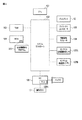
図2は、ウェアラブル端末1のシステム構成を示す図である。
FIG. 2 is a diagram illustrating a system configuration of the
ウェアラブル端末1の本体11には、図1で示したディスプレイ12、操作ボタン13のほか、図2に示されるように、CPU101、システムコントローラ102、RAM103、ROM104、グラフィクスコントローラ105、無線通信モジュール106、複数のセンサ107A,107B,…、EC(Embedded controller)108等が配置されている。
In addition to the
CPU101は、ウェアラブル端末1内の各種コンポーネントの動作を制御するプロセッサである。CPU101は、RAM103を作業領域として利用しながら、ROM104に格納される各種プログラムを実行する。各種プログラムの1つとして、後述する生体情報取得プログラム200が存在する。
The
システムコントローラ102は、CPU101のローカルバスと各種コンポーネントとの間を接続するデバイスである。システムコントローラ102には、RAM103やROM104のアクセス制御を司るメモリコントローラ等、各種コンポーネントを駆動制御するための種々のコントローラが内蔵されている。
The
グラフィクスコントローラ105は、ディスプレイ12を制御する表示コントローラである。ディスプレイ12は、グラフィクスコントローラ105によって生成される表示信号に基づいて画面イメージを表示する。
The
無線通信モジュール106は、例えばIEEE 802.11規格に準拠した無線通信を実行するモジュールである。複数のセンサ107A,107B,…は、例えば、生体情報取得センサ、加速度センサ、照度センサ、温度センサ、湿度センサ、地磁気センサ等である。ここでは、センサ107Aが生体情報取得センサであり、センサ107Bが3軸加速度センサであるものと想定する。各センサの検出値は、システムコントローラ102内のレジスタを経由して、生体情報取得プログラム200を含む様々なプログラムで利用される。
The
EC108は、ウェアラブル端末1内の各種コンポーネントに対する動作用電力の供給制御を司るPSC(Power supply controller)108Aを含むワンチップマイクロコンピュータである。EC108は、操作ボタン13の操作によるユーザからの指示を受け付ける機能を有している。
The EC 108 is a one-chip microcomputer that includes a power supply controller (PSC) 108 </ b> A that controls operation power supply to various components in the
生体情報取得プログラム200は、生体情報取得センサ107Aを用いて、ウェアラブル端末1を装着するユーザの脈拍やSpO2などの生体情報を取得するプログラムである。生体情報取得センサ107Aは、例えば反射式の光電センサであり、人体(腕部)に向けて特定の波長の光を照射すると共に、その(人体(腕部)による)反射光を受光する。生体情報取得プログラム200は、血液中のヘモグロビンにより光が吸収される事象を利用して、生体情報取得センサ107Aにより受光される反射光を解析することにより、ユーザの脈拍やSpO2などを算出する。なお、透過式の光電センサである場合には、生体情報取得センサ107Aは、人体(腕部)を透過する光を受光する。
The biometric
ここで、図3を参照して、生体情報取得センサ107Aの検出値から生体情報取得プログラム200が生体情報を取得する原理について簡単に説明する。
Here, with reference to FIG. 3, the principle by which the biological
血液中には、酸素を運ぶヘモグロビンが存在する。ヘモグロビンは、酸素と結合していないときと酸素と結合しているときとで、吸光率に違いを生じさせるといった性質をもっている。酸素と結合していないヘモグロビンは、還元ヘモグロビン[Hb]、酸素と結合しているヘモグロビンは、酸化ヘモグロビン[HbO2]などと称されている。 There is hemoglobin that carries oxygen in the blood. Hemoglobin has the property of causing a difference in absorbance between when it is not bound to oxygen and when it is bound to oxygen. Hemoglobin not bound to oxygen is called reduced hemoglobin [Hb], and hemoglobin bound to oxygen is called oxygenated hemoglobin [HbO 2 ].
例えば、還元ヘモグロビン[Hb]は、赤色光(例えば波長660nm)を酸化ヘモグロビン[HbO2]よりも多く吸収し、逆に、赤外光(例えば波長940nm)については酸化ヘモグロビン[HbO2]よりも吸収が少ない。そこで、例えば、生体情報取得センサ107Aに、赤色光および赤外光の発光と、それらの反射光の受光とを行わせ、それらの反射光量に基づき、生体情報取得プログラム200は、脈拍やSpO2などを算出する。なお、ここでは、波長660nmと波長940nmとを例示したが、それ以外の波長の光についても、還元ヘモグロビン[Hb]と酸化ヘモグロビン[HbO2]との間では、図3に示すように、その光に対する吸光率に違いが生じる。
For example, reduced hemoglobin [Hb] absorbs more red light (for example, wavelength 660 nm) than oxidized hemoglobin [HbO 2 ], and conversely, for infrared light (for example, wavelength 940 nm), it is more than oxidized hemoglobin [HbO 2 ]. Less absorption. Therefore, for example, the biological
ところで、生体情報取得センサ107Aの検出値から生体情報取得プログラム200が取得する生体情報の精度は、ウェアラブル端末1を装着するユーザの動き、つまり体動が大きい場合、少なからず低下する。生体情報取得センサ107Aと人体(腕部)との間の距離が変動するためである。体動が大きい状況下においても、取得される生体情報の精度を高めるために、例えば2つの波長の光で生体情報を算出していたものを、さらにそれ以外の波長の光も使って、3つ以上の波長の光で生体情報を算出するといったことも考えられる。
By the way, the accuracy of the biometric information acquired by the biometric
しかしながら、光を発光する生体情報取得センサ107Aの消費電力量は、ウェアラブル端末1の総消費電力量に占める割合が小さくない。従って、発光する光の数を単純に増加させることは好ましくない。そこで、本実施形態のウェアラブル端末1は、消費電力の増加を抑止しつつ、体動が大きい場合であっても精度よく生体情報を取得できるようにしたものであり、以下、この点について詳述する。
However, the amount of power consumption of the biological information acquisition sensor 107 </ b> A that emits light is not small in the total power consumption of the
図4は、ウェアラブル端末1の生体情報の取得に関する機能ブロックを示す図である。
FIG. 4 is a diagram illustrating functional blocks related to acquisition of biometric information of the
図4に示すように、生体情報取得プログラム200は、体動監視部201、センサ駆動制御部202および生体情報演算部203を有する。
As illustrated in FIG. 4, the biological
体動監視部201は、加速度センサ107Bの検出値に基づき、ウェアラブル端末1を装着するユーザの動き(体動)が閾値以上となっていないかを監視する。体動が閾値以上である場合、体動監視部201は、その旨をセンサ駆動制御部202に通知する。
The body
なお、ここでは、加速度センサで体動を監視する例を示すが、例えば、体動でウェアラブル端末1とユーザの腕部との間に隙間が生じることを前提として、照度センサで体動を監視するようにしてもよい。その他、体動の監視には、種々のセンサを利用することが可能であり、また、複数のセンサを利用してもよい。
Here, an example in which body motion is monitored by an acceleration sensor is shown, but for example, body motion is monitored by an illuminance sensor on the assumption that a gap is generated between the
センサ駆動制御部202は、生体情報取得センサ107Aの駆動制御を司る。図4に示すように、生体情報取得センサ107Aは、LED(Light emitting diode)駆動部301、複数のLED302、PD(Photo diode)303および信号処理部304を有する。ここでは、複数のLED302として、赤色光(例えば波長660nm)を発光するLED[1]および赤外光(例えば波長940nm)を発光するLED[2]と、この2つとは異なり、かつ、互いに異なる波長の光を発光する2つのLED[3,4]との合計4つのLEDが存在するものと想定する。後者の2つのLED[3,4]は、一方は、還元ヘモグロビン[Hb]の方が酸化ヘモグロビン[HbO2]よりも多く吸収される波長の光を発光し、他方は、酸化ヘモグロビン[HbO2]の方が還元ヘモグロビン[Hb]よりも多く吸収される波長の光を発光するものであることが好ましい。これら複数のLED302とPD303とは、ウェアラブル端末1を装着するユーザの腕部の皮膚に近接する本体11の裏面に配置される。
The sensor
LED駆動部301は、LED302を駆動する。LED駆動部301は、(生体情報取得プログラム200の)センサ駆動制御部202からの指示に応じて、発光するLED302の数を変動させることができる。また、LED駆動部301は、LED302の発光タイミングを示す同期信号を信号処理部304に供給する。
The
PD303は、LED302から発光された光の反射光を受光し、受光量を示す信号を出力する。信号処理部304は、PD303から出力される信号に対し、例えば増幅やフィルタリングといった処理を施すモジュールであって、LED駆動部301からの同期信号に基づき、LED302の発光タイミングと対応するPD303の受光タイミングでPD303から出力される信号に対して当該処理を施すことにより生成される検出値を(生体情報取得プログラム200の)生体情報演算部203に出力する。
The
センサ駆動制御部202は、通常時、(生体情報取得センサ107Aの)LED駆動部301に対して、4つのLED302の内、赤色光(例えば波長660nm)を発光するLED[1]と赤外光(例えば波長940nm)を発光するLED[2]とを発光させるように指示する。これにより、生体情報取得センサ107Aは、図5に示すように、2つのLED302で2つの波長の光をユーザの腕部に向けて照射し、その反射光をPD303で受光して、その受光量を示す検出値を出力する。
The sensor
また、前述したように、体動監視部201は、体動が閾値以上である場合、その旨をセンサ駆動制御部202に通知する。そこで、この通知を受けた場合、センサ駆動制御部202は、(生体情報取得センサ107Aの)LED駆動部301に対して、4つのLED302のすべてを発光させるように指示する。これにより、生体情報取得センサ107Aは、図6に示すように、4つのLED302で4つの波長の光をユーザの腕部に向けて照射し、その反射光をPD303で受光して、その受光量を示す検出値を出力する。
As described above, when the body motion is equal to or greater than the threshold, the body
このように、本ウェアラブル端末1は、体動の状況により、利用する波長を適応的に切り替えることで生体情報の高精度化を実現する。また、本ウェアラブル端末1は、常に多波長を利用するのではなく、必要な時だけ多波長を利用することで消費電力の増加を抑制することができる。
As described above, the
なお、複数のLED302は、PD303に到達するまでの各々が発光する光の経路が略等距離となるように配置されることが好ましい。より具体的には、例えば図7に示すように、複数のLED302は、PD303を中心とする円の円周上に配置されることが好ましい。
In addition, it is preferable that the plurality of
図8は、本ウェアラブル端末1の生体情報の取得時における処理手順を示すフローチャートである。
FIG. 8 is a flowchart showing a processing procedure when the
生体情報の取得時、ウェアラブル端末1は、体動を検出する(ブロックA1)。検出した体動が閾値未満である場合(ブロックA2のNO)、ウェアラブル端末1は、発光させるLEDの数を通常の数に設定する(ブロックA3)。一方、検出した体動が閾値以上である場合(ブロックA2のYES)、ウェアラブル端末1は、発光させるLEDの数を通常よりも多い数に設定する(ブロックA3)。
At the time of acquiring biometric information, the
以上のように、本実施形態のウェアラブル端末1は、消費電力の増加を抑止しつつ、体動が大きい場合であっても精度よく生体情報を取得することを実現する。
As described above, the
なお、以上の説明では、体動が閾値未満の場合と体動が閾値以上の場合とで、生体情報を取得するために利用する光の波長数を2段階に切り換える例を示したが、さらに、体動の大きさに応じて、利用する光の波長数を3段階以上の多段階に切り換えるようにしてもよい。 In the above description, an example has been shown in which the number of wavelengths of light used for acquiring biological information is switched between two levels depending on whether the body motion is less than the threshold value or the body motion is greater than or equal to the threshold value. Depending on the size of body movement, the number of wavelengths of light to be used may be switched between three or more stages.
本実施形態の各種処理はコンピュータプログラムによって実現することができるので、このコンピュータプログラムを格納したコンピュータ読み取り可能な記憶媒体を通じてこのコンピュータプログラムを通常のコンピュータにインストールして実行するだけで、本実施形態と同様の効果を容易に実現することができる。 Since the various processes of the present embodiment can be realized by a computer program, the computer program can be installed in a normal computer through a computer-readable storage medium storing the computer program and executed. Similar effects can be easily realized.
本発明のいくつかの実施形態を説明したが、これらの実施形態は、例として提示したものであり、発明の範囲を限定することは意図していない。これら新規な実施形態は、その他の様々な形態で実施されることが可能であり、発明の要旨を逸脱しない範囲で、種々の省略、置き換え、変更を行うことができる。これら実施形態やその変形は、発明の範囲や要旨に含まれると共に、特許請求の範囲に記載された発明とその均等の範囲に含まれる。 Although several embodiments of the present invention have been described, these embodiments are presented by way of example and are not intended to limit the scope of the invention. These novel embodiments can be implemented in various other forms, and various omissions, replacements, and changes can be made without departing from the scope of the invention. These embodiments and modifications thereof are included in the scope and gist of the invention, and are included in the invention described in the claims and the equivalents thereof.
1…ウェアラブル端末、107A…生体情報取得センサ、107B…加速度センサ、200…生体情報取得プログラム、201…体動監視部、202…センサ駆動制御部、203…生体情報演算部、301…LED駆動部、302…LED、303…PD、304…信号処理部。
DESCRIPTION OF
Claims (6)
赤色光を発光する第1LEDと、赤外光を発光する第2LEDと、前記第1LEDおよび前記第2LEDが発光する光と波長が異なり、かつ、互いに異なる波長の光を発光する第3LEDおよび第4LEDとを含む複数の発光デバイスと、
前記複数の発光デバイスにより発光され、前記電子機器を装着する人体により反射される反射光または前記人体を透過する透過光を受光する受光デバイスと、
前記電子機器を装着する人体の動きを検出するセンサと、
生体情報取得プログラムを含む各種プログラムを実行するCPUと、
を具備し、
前記CPUは、
前記センサにより検出される前記動きの大きさが閾値未満の場合、赤色光を発光する前記第1LEDと赤外光を発光する前記第2LEDとの2つの発光デバイスを発光させ、その反射光または透過光を受光する前記受光デバイスからの出力信号に基づき前記人体の生体情報を取得し、
前記センサにより検出される前記動きの大きさが前記閾値以上の場合、赤色光を発光する前記第1LEDと、赤外光を発光する前記第2LEDと、前記第1LEDおよび前記第2LEDが発光する光と波長が異なり、かつ、互いに異なる波長の光を発光する前記第3LEDおよび前記第4LEDとの4つの発光デバイスを発光させ、その反射光または透過光を受光する前記受光デバイスからの出力信号に基づき前記人体の生体情報を取得する、
電子機器。 An electronic device that is used while attached to a human body,
A first LED that emits red light, a second LED that emits infrared light, and a third LED and a fourth LED that emit light having wavelengths different from those of the light emitted from the first LED and the second LED. A plurality of light emitting devices including:
A light receiving device that receives the reflected light that is emitted by the plurality of light emitting devices and reflected by a human body wearing the electronic device or transmitted light that passes through the human body;
A sensor for detecting movement of a human body wearing the electronic device;
A CPU that executes various programs including a biological information acquisition program;
Comprising
The CPU
When the magnitude of the movement detected by the sensor is less than a threshold value, the two light emitting devices of the first LED that emits red light and the second LED that emits infrared light are caused to emit light, and the reflected light or transmitted light thereof. Acquiring biological information of the human body based on an output signal from the light receiving device that receives light;
When the magnitude of the movement detected by the sensor is equal to or greater than the threshold value, the first LED that emits red light, the second LED that emits infrared light, and the light emitted by the first LED and the second LED. and different wavelength, and causes the light four light emitting devices of the first 3LED and the second 4LED emit light of different wavelengths based on the output signal from the light receiving device for receiving the reflected light or transmitted light Obtaining biological information of the human body,
Electronics.
前記第4LEDは、前記酸化ヘモグロビン[HbO2]の方が前記還元ヘモグロビン[Hb]よりも多く吸収される波長の光を発光する、
請求項1に記載の電子機器。 The third LED emits light having a wavelength at which reduced hemoglobin [Hb] is absorbed more than oxyhemoglobin [HbO2],
The fourth LED emits light having a wavelength at which the oxygenated hemoglobin [HbO 2 ] is absorbed more than the reduced hemoglobin [Hb].
The electronic device according to claim 1.
センサにより前記電子機器を装着する人体の動きを検出することと、
前記センサにより検出される前記動きの大きさが閾値未満の場合、赤色光を発光する第1LEDと赤外光を発光する第2LEDとの2つの発光デバイスを発光させ、その反射光または透過光を受光する受光デバイスからの出力信号に基づき前記人体の生体情報を取得することと、
前記センサにより検出される前記動きの大きさが前記閾値以上の場合、赤色光を発光する前記第1LEDと、赤外光を発光する前記第2LEDと、前記第1LEDおよび前記第2LEDが発光する光と波長が異なり、かつ、互いに異なる波長の光を発光する第3LEDおよび第4LEDとの4つの発光デバイスを発光させ、その反射光または透過光を受光する前記受光デバイスからの出力信号に基づき前記人体の生体情報を取得することと、
を具備する制御方法。 An electronic device control method comprising:
Detecting a movement of a human body wearing the electronic device by a sensor;
When the magnitude of the movement detected by the sensor is less than a threshold value, two light emitting devices, a first LED that emits red light and a second LED that emits infrared light, emit light, and the reflected light or transmitted light is emitted. Acquiring biological information of the human body based on an output signal from a light receiving device that receives light;
When the magnitude of the movement detected by the sensor is equal to or greater than the threshold value, the first LED that emits red light, the second LED that emits infrared light, and the light emitted by the first LED and the second LED. and different wavelengths, and the human body based on the output signal from the light receiving device to emit four light emitting device of the first 3LED and second 4LED emit light of different wavelengths, receiving reflected light or transmitted light Obtaining biometric information of
A control method comprising:
Priority Applications (2)
| Application Number | Priority Date | Filing Date | Title |
|---|---|---|---|
| JP2014172409A JP6415901B2 (en) | 2014-08-27 | 2014-08-27 | Electronic device and control method |
| US14/633,994 US9808197B2 (en) | 2014-08-27 | 2015-02-27 | Electronic apparatus and control method |
Applications Claiming Priority (1)
| Application Number | Priority Date | Filing Date | Title |
|---|---|---|---|
| JP2014172409A JP6415901B2 (en) | 2014-08-27 | 2014-08-27 | Electronic device and control method |
Publications (3)
| Publication Number | Publication Date |
|---|---|
| JP2016047073A JP2016047073A (en) | 2016-04-07 |
| JP2016047073A5 JP2016047073A5 (en) | 2017-08-10 |
| JP6415901B2 true JP6415901B2 (en) | 2018-10-31 |
Family
ID=55401140
Family Applications (1)
| Application Number | Title | Priority Date | Filing Date |
|---|---|---|---|
| JP2014172409A Active JP6415901B2 (en) | 2014-08-27 | 2014-08-27 | Electronic device and control method |
Country Status (2)
| Country | Link |
|---|---|
| US (1) | US9808197B2 (en) |
| JP (1) | JP6415901B2 (en) |
Families Citing this family (6)
| Publication number | Priority date | Publication date | Assignee | Title |
|---|---|---|---|---|
| US10959619B2 (en) * | 2016-03-07 | 2021-03-30 | Samsung Electronics Co., Ltd. | Apparatus and method for acquiring biological information and band for acquiring biological information |
| JP6988061B2 (en) * | 2016-07-15 | 2022-01-05 | 富士フイルムビジネスイノベーション株式会社 | Biometric information measuring device and biometric information measuring program |
| KR102408028B1 (en) | 2017-09-06 | 2022-06-13 | 삼성전자 주식회사 | Method for acquiring biometric information based on wering state and electronic device thereof |
| KR102418120B1 (en) * | 2017-11-01 | 2022-07-07 | 삼성전자 주식회사 | Electronic device comprising a plurality of light emitting unit and a plurality of light receiving unit |
| JP2020178052A (en) * | 2019-04-18 | 2020-10-29 | ローム株式会社 | Light receiving ic, proximity sensor, and electronic device |
| JP2021150671A (en) * | 2020-03-16 | 2021-09-27 | ローム株式会社 | Light receiving ic, proximity sensor, and electronic apparatus |
Family Cites Families (13)
| Publication number | Priority date | Publication date | Assignee | Title |
|---|---|---|---|---|
| US3910701A (en) * | 1973-07-30 | 1975-10-07 | George R Henderson | Method and apparatus for measuring light reflectance absorption and or transmission |
| US5203329A (en) * | 1989-10-05 | 1993-04-20 | Colin Electronics Co., Ltd. | Noninvasive reflectance oximeter sensor providing controlled minimum optical detection depth |
| JPH10216112A (en) * | 1997-02-04 | 1998-08-18 | Hitachi Ltd | Non-invasion biochemical measuring apparatus |
| JPH11155841A (en) * | 1997-12-01 | 1999-06-15 | Nippon Koden Corp | Device and method for body movement noise eliminating pulse oxymetry |
| JP2001198111A (en) * | 1999-11-11 | 2001-07-24 | Nippon Koden Corp | Probe and concentration measuring device of light absorbing substance in organismic tissue |
| US6402690B1 (en) * | 1999-04-23 | 2002-06-11 | Massachusetts Institute Of Technology | Isolating ring sensor design |
| JP2003339678A (en) | 2002-05-30 | 2003-12-02 | Minolta Co Ltd | Instrument for measuring blood state |
| US6879850B2 (en) * | 2002-08-16 | 2005-04-12 | Optical Sensors Incorporated | Pulse oximeter with motion detection |
| JP2007295973A (en) * | 2006-04-27 | 2007-11-15 | Nippon Koden Corp | Pulse oxymeter |
| JP4962195B2 (en) | 2007-08-03 | 2012-06-27 | コニカミノルタオプティクス株式会社 | Pulse oximeter |
| JP5196323B2 (en) | 2009-02-23 | 2013-05-15 | 日本光電工業株式会社 | Blood oxygen saturation measuring device |
| US9734304B2 (en) * | 2011-12-02 | 2017-08-15 | Lumiradx Uk Ltd | Versatile sensors with data fusion functionality |
| JP2013150772A (en) * | 2011-12-29 | 2013-08-08 | Sony Corp | Signal processing apparatus and signal processing method |
-
2014
- 2014-08-27 JP JP2014172409A patent/JP6415901B2/en active Active
-
2015
- 2015-02-27 US US14/633,994 patent/US9808197B2/en active Active
Also Published As
| Publication number | Publication date |
|---|---|
| US9808197B2 (en) | 2017-11-07 |
| US20160058374A1 (en) | 2016-03-03 |
| JP2016047073A (en) | 2016-04-07 |
Similar Documents
| Publication | Publication Date | Title |
|---|---|---|
| JP6415901B2 (en) | Electronic device and control method | |
| US11633117B2 (en) | Multi-channel photoplethysmography sensor | |
| US11317816B1 (en) | Multi-wavelength pulse oximetry | |
| JP4739126B2 (en) | Oxygen saturation measuring device, control program for oxygen saturation measuring device, and recording medium recording control program for oxygen saturation measuring device | |
| US20180000363A1 (en) | Photoplethysmographic sensor configuration | |
| US20120150047A1 (en) | Pulse wave sensor | |
| US11234605B2 (en) | Apparatus for biometric measurement | |
| CN113260308A (en) | Electronic device and method for obtaining information about blood glucose of user | |
| US20150268718A1 (en) | Electronic apparatus and its control method | |
| JP2015142665A (en) | Blood glucose level measuring unit and blood glucose level measuring method | |
| US11246516B2 (en) | Measuring apparatus and measuring method | |
| US20150177270A1 (en) | Wearable device and control method for wearable device | |
| US20150182139A1 (en) | Electronic apparatus, method and storage medium | |
| EP3593718A1 (en) | Measurement device and measurement method | |
| US10034639B2 (en) | Optical vital signs sensor | |
| US20200029903A1 (en) | Wireless vital sign monitoring | |
| EP3929565A1 (en) | Apparatus and method for optically analyzing substance of object | |
| US11666228B2 (en) | Measuring apparatus, measuring method, and program | |
| US20150359447A1 (en) | Electronic device, method, and computer program product | |
| US20210298622A1 (en) | Biological information measurement device | |
| US10849514B2 (en) | Information processing device and information processing method | |
| EP4248844A2 (en) | Pressure sensing for physiological measurements | |
| KR20230040051A (en) | Smart ring detecting bio-signal | |
| CN116687346A (en) | Pressure Sensing for Physiological Measurements |
Legal Events
| Date | Code | Title | Description |
|---|---|---|---|
| A521 | Written amendment |
Free format text: JAPANESE INTERMEDIATE CODE: A523 Effective date: 20170629 |
|
| A621 | Written request for application examination |
Free format text: JAPANESE INTERMEDIATE CODE: A621 Effective date: 20170629 |
|
| A977 | Report on retrieval |
Free format text: JAPANESE INTERMEDIATE CODE: A971007 Effective date: 20180523 |
|
| A131 | Notification of reasons for refusal |
Free format text: JAPANESE INTERMEDIATE CODE: A131 Effective date: 20180619 |
|
| A521 | Written amendment |
Free format text: JAPANESE INTERMEDIATE CODE: A523 Effective date: 20180802 |
|
| TRDD | Decision of grant or rejection written | ||
| A01 | Written decision to grant a patent or to grant a registration (utility model) |
Free format text: JAPANESE INTERMEDIATE CODE: A01 Effective date: 20180904 |
|
| A61 | First payment of annual fees (during grant procedure) |
Free format text: JAPANESE INTERMEDIATE CODE: A61 Effective date: 20181003 |
|
| R151 | Written notification of patent or utility model registration |
Ref document number: 6415901 Country of ref document: JP Free format text: JAPANESE INTERMEDIATE CODE: R151 |
|
| S111 | Request for change of ownership or part of ownership |
Free format text: JAPANESE INTERMEDIATE CODE: R313117 Free format text: JAPANESE INTERMEDIATE CODE: R313121 |
|
| R350 | Written notification of registration of transfer |
Free format text: JAPANESE INTERMEDIATE CODE: R350 |