JP6415037B2 - IMAGING DEVICE, CLIENT DEVICE, IMAGING DEVICE CONTROL METHOD, CLIENT DEVICE CONTROL METHOD, AND PROGRAM - Google Patents
IMAGING DEVICE, CLIENT DEVICE, IMAGING DEVICE CONTROL METHOD, CLIENT DEVICE CONTROL METHOD, AND PROGRAM Download PDFInfo
- Publication number
- JP6415037B2 JP6415037B2 JP2013234250A JP2013234250A JP6415037B2 JP 6415037 B2 JP6415037 B2 JP 6415037B2 JP 2013234250 A JP2013234250 A JP 2013234250A JP 2013234250 A JP2013234250 A JP 2013234250A JP 6415037 B2 JP6415037 B2 JP 6415037B2
- Authority
- JP
- Japan
- Prior art keywords
- image processing
- information
- imaging
- unit
- image
- Prior art date
- Legal status (The legal status is an assumption and is not a legal conclusion. Google has not performed a legal analysis and makes no representation as to the accuracy of the status listed.)
- Active
Links
Images


Classifications
-
- H—ELECTRICITY
- H04—ELECTRIC COMMUNICATION TECHNIQUE
- H04N—PICTORIAL COMMUNICATION, e.g. TELEVISION
- H04N23/00—Cameras or camera modules comprising electronic image sensors; Control thereof
- H04N23/60—Control of cameras or camera modules
- H04N23/66—Remote control of cameras or camera parts, e.g. by remote control devices
- H04N23/661—Transmitting camera control signals through networks, e.g. control via the Internet
-
- G—PHYSICS
- G06—COMPUTING; CALCULATING OR COUNTING
- G06F—ELECTRIC DIGITAL DATA PROCESSING
- G06F3/00—Input arrangements for transferring data to be processed into a form capable of being handled by the computer; Output arrangements for transferring data from processing unit to output unit, e.g. interface arrangements
- G06F3/01—Input arrangements or combined input and output arrangements for interaction between user and computer
- G06F3/048—Interaction techniques based on graphical user interfaces [GUI]
- G06F3/0484—Interaction techniques based on graphical user interfaces [GUI] for the control of specific functions or operations, e.g. selecting or manipulating an object, an image or a displayed text element, setting a parameter value or selecting a range
- G06F3/04842—Selection of displayed objects or displayed text elements
-
- H—ELECTRICITY
- H04—ELECTRIC COMMUNICATION TECHNIQUE
- H04N—PICTORIAL COMMUNICATION, e.g. TELEVISION
- H04N23/00—Cameras or camera modules comprising electronic image sensors; Control thereof
-
- H—ELECTRICITY
- H04—ELECTRIC COMMUNICATION TECHNIQUE
- H04N—PICTORIAL COMMUNICATION, e.g. TELEVISION
- H04N23/00—Cameras or camera modules comprising electronic image sensors; Control thereof
- H04N23/60—Control of cameras or camera modules
- H04N23/63—Control of cameras or camera modules by using electronic viewfinders
- H04N23/631—Graphical user interfaces [GUI] specially adapted for controlling image capture or setting capture parameters
-
- H—ELECTRICITY
- H04—ELECTRIC COMMUNICATION TECHNIQUE
- H04N—PICTORIAL COMMUNICATION, e.g. TELEVISION
- H04N23/00—Cameras or camera modules comprising electronic image sensors; Control thereof
- H04N23/60—Control of cameras or camera modules
- H04N23/667—Camera operation mode switching, e.g. between still and video, sport and normal or high- and low-resolution modes
-
- H—ELECTRICITY
- H04—ELECTRIC COMMUNICATION TECHNIQUE
- H04N—PICTORIAL COMMUNICATION, e.g. TELEVISION
- H04N23/00—Cameras or camera modules comprising electronic image sensors; Control thereof
- H04N23/70—Circuitry for compensating brightness variation in the scene
- H04N23/72—Combination of two or more compensation controls
-
- H—ELECTRICITY
- H04—ELECTRIC COMMUNICATION TECHNIQUE
- H04N—PICTORIAL COMMUNICATION, e.g. TELEVISION
- H04N23/00—Cameras or camera modules comprising electronic image sensors; Control thereof
- H04N23/70—Circuitry for compensating brightness variation in the scene
- H04N23/73—Circuitry for compensating brightness variation in the scene by influencing the exposure time
-
- H—ELECTRICITY
- H04—ELECTRIC COMMUNICATION TECHNIQUE
- H04N—PICTORIAL COMMUNICATION, e.g. TELEVISION
- H04N23/00—Cameras or camera modules comprising electronic image sensors; Control thereof
- H04N23/70—Circuitry for compensating brightness variation in the scene
- H04N23/741—Circuitry for compensating brightness variation in the scene by increasing the dynamic range of the image compared to the dynamic range of the electronic image sensors
-
- H—ELECTRICITY
- H04—ELECTRIC COMMUNICATION TECHNIQUE
- H04N—PICTORIAL COMMUNICATION, e.g. TELEVISION
- H04N25/00—Circuitry of solid-state image sensors [SSIS]; Control thereof
- H04N25/50—Control of the SSIS exposure
- H04N25/53—Control of the integration time
-
- H—ELECTRICITY
- H04—ELECTRIC COMMUNICATION TECHNIQUE
- H04N—PICTORIAL COMMUNICATION, e.g. TELEVISION
- H04N25/00—Circuitry of solid-state image sensors [SSIS]; Control thereof
- H04N25/50—Control of the SSIS exposure
- H04N25/57—Control of the dynamic range
- H04N25/58—Control of the dynamic range involving two or more exposures
- H04N25/587—Control of the dynamic range involving two or more exposures acquired sequentially, e.g. using the combination of odd and even image fields
- H04N25/589—Control of the dynamic range involving two or more exposures acquired sequentially, e.g. using the combination of odd and even image fields with different integration times, e.g. short and long exposures
Landscapes
- Engineering & Computer Science (AREA)
- Multimedia (AREA)
- Signal Processing (AREA)
- Human Computer Interaction (AREA)
- General Engineering & Computer Science (AREA)
- Theoretical Computer Science (AREA)
- Physics & Mathematics (AREA)
- General Physics & Mathematics (AREA)
- Studio Devices (AREA)
- Closed-Circuit Television Systems (AREA)
- Facsimiles In General (AREA)
- Accessory Devices And Overall Control Thereof (AREA)
Description
本発明は、撮像装置、外部装置、撮像システム、撮像装置の制御方法、外部装置の制御方法、撮像システムの制御方法、及びプログラムに関するものである。特に、撮像画像を明るくする処理に用いられて好適である。 The present invention relates to an imaging apparatus, an external apparatus, an imaging system, an imaging apparatus control method, an external apparatus control method, an imaging system control method, and a program. In particular, it is suitable for use in a process for brightening a captured image.
従来から、室内から屋外を撮像するような場合、背景が明るくて被写体が黒くなって見難くなってしまう問題がある。このような問題を解決する技術として、撮像部から出力された撮像画像を明るくする技術が複数知られている。 Conventionally, when taking an image from indoor to outdoor, there is a problem that the background becomes bright and the subject becomes black and difficult to see. As a technique for solving such a problem, a plurality of techniques for brightening a captured image output from an imaging unit are known.
例えば、撮像画像のゲイン補正等を行うことにより、撮像画像を明るくする逆光補正処理がある。また、複数の撮像画像を合成することにより、合成された撮像画像をワイドダイナミックレンジ化するワイドダイナミックレンジ処理が知られている。ここで、特許文献1には、露光時間の異なる複数の撮像画像を合成することにより、ダイナミックレンジが通常よりも大きな撮像画像を生成する技術が開示されている。 For example, there is a backlight correction process that brightens the captured image by performing gain correction of the captured image. In addition, wide dynamic range processing is known in which a plurality of captured images are combined to make the combined captured image a wide dynamic range. Here, Patent Document 1 discloses a technique for generating a captured image having a larger dynamic range than usual by combining a plurality of captured images having different exposure times.
また、上述の技術の一例として、銀塩写真では、ダイナミックレンジの大きな写真を得るために、暗室内で行われる覆い焼き処理というものがある。そこで、この覆い焼き処理をデジタル画像処理によって実現した、明暗差のある被写体、特に逆光下の被写体が映った撮像画像を補正する技術(デジタル覆い焼き処理)がある。さらに、このデジタル覆い焼き処理では、この処理の強度を調整するために、撮像画像のゲイン等が変更される。 Further, as an example of the above-described technique, silver halide photography includes dodging processing performed in a dark room in order to obtain a photograph with a large dynamic range. Therefore, there is a technique (digital dodging process) that corrects a captured image in which an object having a difference in brightness, particularly an object under backlight, is realized by performing this dodging process by digital image processing. Further, in this digital dodging process, the gain of the captured image is changed in order to adjust the intensity of this process.
そして、上述の技術の他の例として、単一の撮像画像の露出を補正する処理を適用することで、被写体を識別しやすい撮像画像を出力する処理も知られている。 As another example of the above-described technique, a process of outputting a captured image that easily identifies a subject by applying a process of correcting the exposure of a single captured image is also known.
さらに、近年、1台の撮像装置に、これら複数の処理が搭載されることもある。その上、ネットワーク技術の急速な普及とともに、このような撮像装置を外部装置からネットワークを介して制御したいというユーザ・ニーズは、ますます高まっている。 Furthermore, in recent years, a plurality of processes may be mounted on a single imaging apparatus. In addition, with the rapid spread of network technology, the user needs to control such an imaging device from an external device via a network is increasing.
しかしながら、上述のような撮像装置において、これら複数の処理を同時に動作させてしまうと、撮像画像が明るくなり過ぎてしまうことがあった。例えば、撮像画像に対し、逆光補正処理、ワイドダイナミックレンジ処理、及びデジタル覆い焼き処理を同時に施してしまうと、この撮像画像が明るくなり過ぎてしまうことがあった。 However, in the imaging apparatus as described above, if these multiple processes are operated simultaneously, the captured image may become too bright. For example, if the captured image is subjected to backlight correction processing, wide dynamic range processing, and digital dodging processing at the same time, the captured image may become too bright.
さらに、これら複数の処理を撮像画像に同時に適用することでこの撮像画像が明るくなり過ぎてしまうか否かは、被写体に依存する。しかしながら、上述の撮像装置が屋外を撮像している場合や被写体が動いている場合を想定すると、被写体は、時々刻々と変化してしまう。 Furthermore, whether or not the captured image becomes too bright by simultaneously applying the plurality of processes to the captured image depends on the subject. However, assuming that the above-described imaging device is imaging the outdoors or the subject is moving, the subject changes from moment to moment.
その上、上述のような撮像装置において、撮像画像が明るくなり過ぎてしまうか否かは、それぞれの処理が撮像画像をどの程度明るくするのかにも依存する。しかし、それぞれの処理が撮像画像を明るくする程度は、この撮像装置の機種やこの撮像装置のメーカーによって異なってしまう。 In addition, in the imaging apparatus as described above, whether or not a captured image becomes too bright depends on how bright each captured process makes the captured image. However, the degree to which each process brightens the captured image varies depending on the model of the imaging apparatus and the manufacturer of the imaging apparatus.
したがって、上述の撮像装置が遠隔地に設置されていると、外部装置を操作するユーザが、撮像画像が明るくなり過ぎないよう、この撮像装置の被写体の変化、この撮像装置の機種やメーカーを考慮し、それぞれの処理の動作を制御することは、困難であった。 Therefore, when the above-described imaging device is installed in a remote place, the user operating the external device considers the change in the subject of the imaging device, the model and manufacturer of the imaging device so that the captured image does not become too bright. However, it has been difficult to control the operation of each processing.
本発明は、上記のような点に鑑みてなされたものであり、撮像画像を明るくする第1及び第2の処理のそれぞれの動作を前記第1及び第2の処理のそれぞれの効果に応じて制御する必要性を減ずることができる。 The present invention has been made in view of the above points, and each operation of the first and second processes for brightening the captured image is performed in accordance with the effects of the first and second processes. The need to control can be reduced.
上記目的を達成するために、本発明の撮像装置は、クライアント装置とネットワーク経由で通信する撮像装置であって、撮像手段と、前記撮像手段から出力された撮像画像の明るさを第一の画像処理を実行することにより変化させる第一の画像処理手段と、前記撮像手段から出力された撮像画像の明るさを前記第一の画像処理とは異なる第二の画像処理を実行することにより変化させる第二の画像処理手段と、前記第一の画像処理を制御するための第一の画像処理情報または前記第二の画像処理を制御するための第二の画像処理情報を含むコマンドを、前記クライアント装置からネットワークを介して受信する受信手段と、前記受信手段で受信されたコマンドに基づき、前記第一の画像処理または前記第二の画像処理を制御する制御手段と、を備え、前記第一の画像処理情報は、少なくとも前記第一の画像処理を実行させるか否かを示す情報を含み、前記第二の画像処理情報は、少なくとも前記第二の画像処理を実行させることを示す情報、前記第二の画像処理を実行させないことを示す情報、及び前記第二の画像処理を実行させるか否かを前記撮像装置が自動で判断することを示す情報、のいずれかを含むことを特徴とする。 In order to achieve the above object, an imaging apparatus according to the present invention is an imaging apparatus that communicates with a client apparatus via a network, wherein the brightness of a captured image output from the imaging means and the imaging means is defined as a first image. a first image processing means for changing by performing the process, varied by performing different second image processing to the first image processing the brightness of the imaged image output from said image pickup means a second image processing unit, the command including the second image processing information for controlling the first image processing information or the second image processing for controlling said first image processing, the client receiving means for receiving from the apparatus via a network, and a control means based on said received by the receiving unit command, and controls the first image processing or the second image processing, Wherein the first image processing information includes information indicating whether to execute at least the first image processing, the second image processing information may be let execute at least the second image processing information indicating, including the second information indicating that not execute the image processing, and information indicating whether to execute the second image processing to the image pickup device is determined automatically, either the It is characterized by that.
本発明によれば、撮像画像を明るくする第1及び第2の処理のそれぞれの動作を前記第1及び第2の処理のそれぞれの効果に応じて制御する必要性を減ずることができる。 According to the present invention, it is possible to reduce the necessity of controlling the operations of the first and second processes for brightening the captured image according to the effects of the first and second processes.
以下に、本発明の実施形態について、図面を参照しながら詳細に説明する。以下に、本発明の好ましい実施の形態を、添付の図面に基づいて詳細に説明する。 Embodiments of the present invention will be described below in detail with reference to the drawings. Hereinafter, preferred embodiments of the present invention will be described in detail with reference to the accompanying drawings.
なお、以下の実施例において示す構成は一例に過ぎず、本発明は、図示された構成に限定されるものではない。また、以下の実施例におけるコマンドは、例えばOpen Network Video Interface Forum(以下ONVIFと称する場合がある)規格に基づいて定められているものとする。 The configurations shown in the following embodiments are merely examples, and the present invention is not limited to the illustrated configurations. In addition, the commands in the following embodiments are defined based on, for example, the Open Network Video Interface Forum (hereinafter sometimes referred to as ONVIF) standard.
(実施例1)
以下に、図1を参照して本実施例に係るネットワーク構成について説明する。より詳細には、図1は、本実施例に係る監視システムのシステム構成の一例を示す図である。
Example 1
The network configuration according to this embodiment will be described below with reference to FIG. More specifically, FIG. 1 is a diagram illustrating an example of a system configuration of the monitoring system according to the present embodiment.
本実施例における監視システムにおいて、動画像を撮像する監視カメラ1000とクライアント装置2000とは、IPネットワーク網1500を介して(ネットワーク経由で)相互に通信可能な状態で接続される。これにより、監視カメラ1000は、撮像画像をIPネットワーク網1500経由でクライアント装置2000に配信することができる。
In the monitoring system according to the present embodiment, the
なお、本実施例におけるクライアント装置2000は、PC等の外部装置の一例である。又、本実施例における監視システムは、撮像システムに相当する。
Note that the
また、IPネットワーク網1500は、例えばEthernet(登録商標)等の通信規格を満足する複数のルータ、スイッチ、ケーブル等から構成されるものとする。しかしながら、本実施例においては、監視カメラ1000とクライアント装置2000との間の通信を行うことができるものであれば、その通信規格、規模、構成を問わない。
The
例えば、IPネットワーク網1500は、インターネットや有線LAN(Local Area Network)、無線LAN(Wireless LAN)、WAN(Wide Area Network)等により構成されていても良い。なお、本実施例における監視カメラ1000は、例えば、PoE(Power Over Ethernet(登録商標))に対応していても良く、LANケーブルを介して電力を供給されても良い。
For example, the
クライアント装置2000は、監視カメラ1000に対し、各種コマンドを送信する。これらのコマンドは、例えば、監視カメラ1000の撮像方向及び画角を変更させるためのコマンド、撮像パラメータを変更するためのコマンド、画像ストリーミングを開始させるためのコマンド等である。
The
一方、監視カメラ1000は、これらのコマンドに対するレスポンスや画像ストリーミングをクライアント装置2000に送信する。また、監視カメラ1000は、クライアント装置2000から受信した画角を変更するためのコマンドに応じて画角を変更する。
On the other hand, the
続いて、図2は、本実施例に係る監視カメラ1000のハードウェア構成の一例を示す図である。
Next, FIG. 2 is a diagram illustrating an example of a hardware configuration of the
図2における制御部1001は、監視カメラ1000の各構成要素を統括的に制御する。また、制御部1001は、CPU(Central Processing Unit)により構成される。そして、制御部1001は、記憶部1002に記憶されたプログラムを実行する。又は、制御部1001は、ハードウェアを用いて制御を行うこととしても良い。
A
記憶部1002は、主に制御部1001が実行するプログラム格納領域、プログラム実行中のワーク領域、後述する撮像部1004で生成される撮像画像の格納領域等、様々なデータの格納領域として使用される。また、通信部1003は、各制御コマンドをクライアント装置2000から受信する。また、通信部1003は、各制御コマンドをクライアント装置2000に送信する。
The
撮像部1004は、不図示の撮像光学系、及びCCDやCMOS等の撮像素子などから構成される。この撮像部1004は、この撮像光学系により結像された被写体の像を撮像することにより、アナログ信号を生成する。また、撮像部1004は、生成したアナログ信号をデジタルデータに変換する。
The
さらに、撮像部1004は、変換したデジタルデータを撮像画像として、記憶部1002、露出補正処理部1005、及びワイドダイナミックレンジ画像合成処理部1006に出力する。
Further, the
露出補正処理部1005は、撮像部1004から出力された1枚の撮像画像を解析し、記憶部1002が記憶する画像処理設定の内容に基づき、この撮像画像に対して露出補正処理を行う。また、露出補正処理部1005は、露出補正処理を行った撮像画像を記憶部1002に出力する。
The exposure
なお、本実施例における露出補正処理には、逆光補正処理、及び暗部補正処理等が含まれる。ここで、逆光補正処理とは、撮像画像のゲイン補正等により、逆光状況における暗部を含んだ撮像画像の全体を明るくする処理である。 The exposure correction process in this embodiment includes a backlight correction process, a dark part correction process, and the like. Here, the backlight correction process is a process that brightens the entire captured image including the dark part in the backlight condition by, for example, gain correction of the captured image.
また、暗部補正処理とは、この撮像画像に含まれる暗部を判定し、ゲイン補正等でこの判定された暗部を重点的に明るく補正する画像処理である。しかし、この暗部補正処理は、この撮像画像に含まれる明るい部分も明るくしてしまうことがある。このため、この暗部補正処理が逆光補正処理及び後述のワイドダイナミックレンジ画像合成処理とともに実行されると、撮像部1004から出力された撮像画像が明るくなり過ぎてしまうことがある。
The dark part correction process is an image process in which a dark part included in the captured image is determined and the determined dark part is intensively corrected by gain correction or the like. However, this dark portion correction processing may brighten bright portions included in the captured image. For this reason, when this dark part correction process is executed together with the backlight correction process and the wide dynamic range image composition process described later, the captured image output from the
また、本実施例における露出補正処理は、撮像部1004の露出条件を設定する露出設定機能を備える。ここで、露出条件とは、撮像部1004に含まれる撮像光学系の絞りの値、及び撮像部1004に含まれる撮像素子の露光時間(蓄積時間)等が含まれる。
Further, the exposure correction process in the present embodiment includes an exposure setting function for setting the exposure condition of the
なお、本実施例における露出補正処理部1005は、撮像部1004の露出条件を設定し、撮像部1004が設定された露出条件で被写体を撮像して生成した1枚の撮像画像を取得する露出設定部に相当する。
Note that the exposure
1006は、ワイドダイナミックレンジ画像合成処理部である。以下、ワイドダイナミックレンジをWDR、またワイドダイナミックレンジ画像合成処理をWDR処理と省略することがある。
WDR画像合成処理部1006は、記憶部1002が記憶する画像処理設定の内容に基づき、撮像部1004から出力された撮像画像のダイナミックレンジを拡大するWDR処理を実行する。
The WDR image
このWDR処理は、撮像部1004から出力された露光条件の異なる複数の画像から、これら複数の画像の最適な明るさの部分を判定して合成することにより、ダイナミックレンジの広い1枚の合成された撮像画像を生成するものである。そして、WDR画像合成処理部1006は、生成した合成撮像画像を記憶部1002に出力する。
In this WDR process, a single image having a wide dynamic range is synthesized from a plurality of images output from the
なお、本実施例における露光条件とは、撮像部1004に含まれる撮像素子の露光時間(蓄積時間)等である。また、本実施例におけるWDR画像合成処理部1006は、撮像部1004が異なる露光条件で被写体を撮像して生成した複数の撮像画像を合成することにより、この合成された撮像画像を1枚生成する合成部に相当する。
Note that the exposure conditions in this embodiment are the exposure time (accumulation time) of the image sensor included in the
圧縮符号化部1007は、撮像部1004、露出補正処理部1005、及びWDR画像合成処理部1006が出力する撮像画像に対し、圧縮符号化設定の内容に基づき、JPEG、H.264、或いはH.265等の形式に基づき圧縮符号化処理を行う。この圧縮符号化設定は、記憶部1002に記憶されている。そして、圧縮符号化部1007は、圧縮符号化処理を行った撮像画像を、記憶部1002に出力する。
The
なお、本実施例における監視カメラ1000は、ストリーミング配信をクライアント装置2000から要求された場合、この要求の内容に基づき、圧縮符号化部1007から出力された撮像画像を、通信部1003を介して外部にストリーミング配信する。
Note that the
続いて、図3は、本実施例に係るクライアント装置2000のハードウェア構成の一例を示す図である。本実施例におけるクライアント装置2000は、IPネットワーク網1500に接続されるコンピュータ装置として構成される。
Next, FIG. 3 is a diagram illustrating an example of a hardware configuration of the
図3における制御部2001は、クライアント装置2000の全体の制御を行う。制御部2001は、例えば、CPUにより構成され、後述の記憶部2002に記憶されたプログラムを実行する。又は、制御部2001は、ハードウェアを用いて制御を行うこととしてもよい。そして、記憶部2002は、制御部2001が実行するプログラム格納領域、プログラム実行中のワーク領域、データの格納領域として使用される。
A
通信部2003は、制御部2001の指示を受け、監視カメラ1000にコマンド等を送信する。又、通信部2003は、監視カメラ1000から、コマンドのレスポンスやストリーミング配信された撮像画像等を受信する。
The
入力部2004は、例えば、ボタン、十字キ―、タッチパネル、マウスなどで構成される。この入力部2004は、ユーザからの指示の入力を受け付ける。例えば、入力部2004は、ユーザからの指示として、監視カメラ1000に対する各種のコマンドの送信指示の入力を受け付けることができる。
The
また、入力部2004は、ユーザから監視カメラ1000に対する命令送信指示が入力されると、制御部2001にこの入力があった旨を通知する。そして、制御部2001は、入力部2004に入力された指示に応じて、監視カメラ1000に対する命令を生成する。次に、制御部2001は、通信部2003に指示し、生成した命令を監視カメラ1000に送信させる。
In addition, when a command transmission instruction to the
さらに、入力部2004は、制御部2001が記憶部2002に記憶されたプログラムを実行することにより生成されるユーザへの問い合わせメッセージ等に対するユーザの応答の入力を受け付けることができる。
Furthermore, the
復号部2005は、通信部2003から出力された撮像画像を復号し且つ伸長する。そして、復号部2005は、この復号し且つ伸長された撮像画像を表示部2006に出力する。これにより、表示部2006は、復号部2005から出力された撮像画像に対応する画像を表示する。
The
なお、表示部2006は、制御部2001が記憶部2002に記憶されたプログラムを実行することにより生成されるユーザへの問い合わせメッセージ等を表示させることができる。
The
以上、監視カメラ1000及びクライアント装置2000のそれぞれの内部構成について説明したが、図2及び図3に示す処理ブロックは、本発明における撮像装置及び外部装置の好適な実施例を説明したものであり、この限りではない。音声入力部や音声出力部を備えるなど、本発明の要旨の範囲内で、種々の変形及び変更が可能である。
As described above, the internal configurations of the
続いて、図4は、監視カメラ1000とクライアント装置2000との間における、ストリーミング配信される撮像画像のパラメータの設定開始から撮像画像がストリーミング配信されるまでの、典型的なコマンドシーケンスを説明するためのシーケンス図である。
Next, FIG. 4 illustrates a typical command sequence between the
なお、本実施例におけるトランザクションとは、クライアント装置2000から監視カメラ1000へ送信されるコマンドと、それに対して監視カメラ1000がクライアント装置2000へ返送するレスポンスのペアのことを指している。
Note that the transaction in this embodiment refers to a pair of a command transmitted from the
図4における6000は、ネットワーク機器接続のトランザクションである。クライアント装置2000は、ネットワーク機器を接続するためのProbeコマンドをユニキャスト、或いはマルチキャストでIPネットワーク網1500に送信する。ネットワークに接続されている監視カメラ1000は、コマンド受け付け可能となったことを示すProbeMatchレスポンスをクライアント装置2000へ返送する。
6000 in FIG. 4 is a network device connection transaction. The
6001は、Subscribeのトランザクションである。このトランザクションにより、クライアント装置2000は、監視カメラ1000に対し、イベント配信を行うよう指示することができる。
6002は、GetProfilesトランザクションである。このトランザクションは、配信プロファイルに相当するMediaProfileを取得するためのトランザクションである。ここで、MediaProfileとは、監視カメラ1000の各種設定項目を関連づけて記憶するためのパラメータセットである。
この各種設定項目は、このMediaProfileのIDであるProfileTokenと、後述のVideoSourceConfiguration、後述のVideoEncoderConfigurationのほか、音声のエンコーダ等を含む。そして、MediaProfileは、これら各種設定項目へのリンクを保持する。 These various setting items include ProfileToken, which is the ID of this MediaProfile, VideoSourceConfiguration described later, VideoEncoderConfiguration described later, an audio encoder, and the like. MediaProfile holds links to these various setting items.
クライアント装置2000は、GetProfilesコマンドを監視カメラ1000に送信する。そして、GetProfilesコマンドを受信した監視カメラ1000は、MediaProfileのリストをクライアント装置2000に送信する。
The
これにより、クライアント装置2000は、MediaProfileを識別するための配信プロファイルIDとともに、監視カメラ1000で現在使用可能なMediaProfileのリストを取得する。なお、クライアント装置2000は、監視カメラ1000内に存在する配信可能な配信プロファイル設定を配信プロファイルIDで識別している。
As a result, the
6003は、GetVideoSourcesコマンドのトランザクションである。このコマンドにより、クライアント装置2000は、監視カメラ1000が保持するVideoSourceのリストを取得する。
ここで、VideoSourceとは、監視カメラ1000が備える1つの撮像部1004の性能を示すパラメータの集合体である。また、VideoSourceは、VideoSourceのIDであるVideoSourceTokenと、撮像部1004が出力可能な撮像画像の解像度を示すResolutionを含む。
Here, VideoSource is a set of parameters indicating the performance of one
クライアント装置2000は、GetVideoSourcesコマンドを監視カメラ1000に送信する。そして、GetVideoSourcesコマンドを受信した監視カメラ1000は、このコマンドのレスポンスをクライアント装置2000に返送する。
The
6004は、GetVideoSourceConfigurationsトランザクションである。このトランザクションは、監視カメラ1000の保持するVideoSourceConfigurationのリストを取得するためのトランザクションである。
ここで、VideoSourceConfigurationとは、監視カメラ1000が備えるVideoSourceをMediaProfileに関連付けるパラメータの集合体である。また、VideoSourceConfigurationは、VideoSourceが出力する撮像画像のうち、どの部分を切り出して配信画像とするかを指定するBoundsを含む。
Here, the VideoSourceConfiguration is a set of parameters that associates the VideoSource included in the
なお、以下、VideoSourceConfigurationを、VSCと称することがある。 Hereinafter, VideoSourceConfiguration may be referred to as VSC.
クライアント装置2000は、GetVideoSourceConfigurationsコマンドを監視カメラ1000に送信する。そして、GetVideoSourceConfigurationsコマンドを受信した監視カメラ1000は、監視カメラ1000が保持するVSCのIDを含むリストをクライアント装置2000に返送する。
The
6005は、GetVideoEncorderConfigurationsトランザクションである。このトランザクションにより、クライアント装置2000は、監視カメラ1000が保持するVideoEncorderConfigurationのリストを取得する。
Reference numeral 6005 denotes a GetVideoEncoderConfigurations transaction. Through this transaction, the
クライアント装置2000は、GetVideoEncorderConfigurationsコマンドを監視カメラ1000に送信する。又、このコマンドを受信した監視カメラ1000は、このコマンドのレスポンスを返送する。
The
ここで、VideoEncoderConfigurationとは、撮像部1004から出力された撮像画像の圧縮符号化に関する圧縮符号化設定をMediaProfileに関連付けるパラメータの集合体である。以下、VideoEncorderConfigurationをVECと称することがある。この圧縮符号化設定は、記憶部1002に記憶されている。
Here, VideoEncoderConfiguration is a set of parameters for associating the compression coding setting related to the compression coding of the captured image output from the
VECは、VECのIDであるVECToken、圧縮符号化方式(JPEGやH.264等)を指定するEncoding、出力画像の解像度を指定するResolution、圧縮符号化品質を指定するQualityを含む。更に、VECは、監視カメラ1000から出力される撮像画像に関し、最大フレームレートを指定するFramerateLimit、及び最大ビットレートを指定するBitrateLimitを含む。
VEC includes VECTToken, which is an ID of VEC, Encoding that specifies a compression encoding method (JPEG, H.264, etc.), Resolution that specifies the resolution of an output image, and Quality that specifies compression encoding quality. Further, the VEC includes a FramerateLimit that specifies the maximum frame rate and a BitrateLimit that specifies the maximum bit rate for the captured image output from the
例えば、監視カメラ1000は、VideoSource、及びVSCの内容に基づいて撮像部1004から出力された撮像画像を、このVEC内に設定されたパラメータに従って、圧縮符号化し、通信部1003を介してクライアント装置2000に配信する。
For example, the
6006は、GetVideoEncorderConfigurationOptionsトランザクションである。このトランザクションにより、クライアント装置2000は、IDによって指定されたVECに関し、監視カメラ1000が受け付け可能な各パラメータの選択肢や設定値の範囲を取得することができる。
クライアント装置2000は、GetVideoEncorderConfigurationOptionsコマンドを監視カメラ1000に送信する。このコマンドを受信した監視カメラ1000は、このコマンドのレスポンスを返送する。このトランザクションにより、クライアント装置2000は、記憶部1002に記憶されている圧縮符号化設定のIDを含むリストを監視カメラ1000から取得する。
The
6007は、CreateProfileのトランザクションである。このトランザクションは、配信プロファイルの作成を要求するためのトランザクションである。クライアント装置2000は、CreateProfileコマンドを監視カメラ1000に送信する。このコマンドを受信した監視カメラ1000は、このコマンドのレスポンスを返送する。
このトランザクションにより、クライアント装置2000は、配信プロファイルを監視カメラ1000内に新たに作成し、作成した配信プロファイルのIDを得ることができる。又、監視カメラ1000は、この新たに作成された配信プロファイルを記憶する。
Through this transaction, the
このトランザクションのコマンド処理後、監視カメラ1000は、MediaProfile変更通知イベントをクライアント装置2000に送信することで、MediaProfileに何らかの変更があったことをクライアント装置2000に通知する。
After the command processing of this transaction, the
6008は、AddVideoSourceConfigurationのトランザクションである。このトランザクションは、VSCの追加を要求するためのトランザクションである。クライアント装置2000は、AddVideoSourceConfigurationのコマンドを監視カメラ1000に送信する。このコマンドを受信した監視カメラ1000は、このコマンドのレスポンスをクライアント装置2000に返送する。
このトランザクションにおいて、クライアント装置2000は、6007で取得した配信プロファイルIDと6004で取得したVSCのIDとを指定する。これにより、クライアント装置2000は、指定した配信プロファイルIDに対応するMediaProfileに対し、指定したVSCのIDに対応する所望のVSCを関連付けることができる。
In this transaction, the
一方、監視カメラ1000は、クライアント装置2000で指定された配信プロファイルIDに対応するMediaProfileと、クライアント装置2000により指定されたVSCのIDに対応する所望のVSCと、を関連付けて記憶部1002に記憶させる。
On the other hand, the
6009は、AddVideoEncorderConfigurationのトランザクションである。このトランザクションは、VECの追加を要求するためのトランザクションである。クライアント装置2000は、AddVideoEncorderConfigurationのコマンドを監視カメラ1000に送信する。監視カメラ1000は、このコマンドのレスポンスをクライアント装置2000に返送する。
このトランザクションにおいて、クライアント装置2000は、6007で取得した配信プロファイルIDと6005で取得したVECのIDとを指定する。これにより、クライアント装置2000は、指定した配信プロファイルIDに対応するMediaProfileに対し、指定したVECのIDに対応するVECを関連付けることができる。
In this transaction, the
一方、監視カメラ1000は、クライアント装置2000により指定された配信プロファイルIDに対応するMediaProfileと、クライアント装置2000により指定されたVECのIDに対応する所望のVECと、を関連付けて記憶する。
On the other hand, the
6008、6009のトランザクションの処理後、監視カメラ1000は、MediaProfile変更通知イベントをクライアント装置2000に送信することで、MediaProfileに何らかの変更があったことをクライアント装置2000に通知する。
After processing the
6010は、SetVideoEncorderConfigurationのトランザクションである。このトランザクションは、VECの各パラメータを設定するためのトランザクションである。クライアント装置2000は、SetVideoEncorderConfigurationのコマンドを監視カメラ1000に送信する。
このコマンドを受信した監視カメラ1000は、このコマンドのレスポンスを返送する。このトランザクションにより、クライアント装置2000は、6005で取得したVECの内容を、6006で取得した選択肢に基づいて設定する。例えば、圧縮符号化方式や切出しサイズを変更する。監視カメラ1000は、設定された圧縮符号化設定等の内容を記憶する。
The
このトランザクションの処理後、監視カメラ1000は、VEC変更通知イベントをクライアント装置2000に送信することにより、VECに何らかの変更があったことをクライアント装置2000に通知する。
After processing this transaction, the
6011は、GetStreamUriのトランザクションである。このトランザクションは、配信アドレスの取得を要求するためのトランザクションである。このトランザクションにて、クライアント装置2000は、6007で取得した配信プロファイルIDを指定し、指定した配信プロファイルの設定に基づいてストリーミング配信される撮像画像等を取得するためのアドレス(URI)を取得する。
監視カメラ1000は、クライアント装置2000により指定された配信プロファイルIDに関連付けられているVSC、及びVECの内容に対応する画像をストリーミング配信するためのアドレスを、クライアント装置2000に返送する。
The
6012は、DESCRIBEのトランザクションである。このトランザクションは、配信情報の取得を要求するためのトランザクションである。クライアント装置2000は、DESCRIBEのコマンドを監視カメラ1000に送信する。このコマンドを受信した監視カメラ1000は、このコマンドのレスポンスをクライアント装置2000に返送する。
このトランザクションにおいて、クライアント装置2000は、6011で取得したURIを使用してDESCRIBEコマンドを実行することにより、監視カメラ1000がストリーミング配信するコンテンツの情報を要求して取得する。
In this transaction, the
6013は、SETUPのトランザクションである。このトランザクションは、配信設定を要求するためのトランザクションである。クライアント装置2000は、SETUPのコマンドを監視カメラ1000に送信する。このコマンドを受信した監視カメラ1000は、このコマンドのレスポンスをクライアント装置2000に返送する。
このトランザクションにおいて、クライアント装置2000は、6012で取得した配信情報に関する詳細データに基づき、監視カメラ1000に対してストリーミングの準備を行わせる。このコマンドを実行することにより、クライアント装置2000と監視カメラ1000との間で、セッション番号を含むストリームの伝送方法が共有される。
In this transaction, the
6014は、PLAYのトランザクションである。このトランザクションは、ストリーミング配信を開始させるためのトランザクションである。クライアント装置2000は、PLAYのコマンドを監視カメラ1000に送信する。このコマンドを受信した監視カメラ1000は、このコマンドのレスポンスをクライアント装置2000に返送する。
クライアント装置2000は、PLAYのコマンドを監視カメラ1000に送信する際、6013で取得したセッション番号を用いることで、監視カメラ1000にストリーミング配信の開始を要求することができる。
When the
6015は、監視カメラ1000からクライアント装置2000に配信されるストリームである。6014で開始を要求されたストリームを6013において共有された伝送方法によって配信する。
6016は、TEARDOWNのトランザクションである。このトランザクションは、ストリーミング配信を停止させるためのトランザクションである。クライアント装置2000は、TEARDOWNのコマンドを監視カメラ1000に送信する。このコマンドを受信した監視カメラ1000は、このコマンドのレスポンスを返送する。
このトランザクションにおいて、クライアント装置2000は、6013にて取得したセッション番号を指定してTEADOWNコマンドを実行することにより、監視カメラ1000に対してストリーミング配信の停止を要求することができる。
In this transaction, the
続いて、図5は、監視カメラ1000とクライアント装置2000との間における、画像処理設定に相当するImagingSettingを変更するための、典型的なコマンドシーケンスを説明するためのシーケンス図である。
Next, FIG. 5 is a sequence diagram for explaining a typical command sequence for changing ImagingSetting corresponding to the image processing setting between the
図5における6050は、GetServicesのトランザクションである。このトランザクションにより、クライアント装置2000は、監視カメラ1000がサポートしているWebサービスの種類と各Webサービスを利用するためのアドレスURIを取得することができる。
クライアント装置2000は、GetServicesコマンドを監視カメラ1000に送信する。このコマンドを受信した監視カメラ1000は、このコマンドのレスポンスを返送する。
The
6051は、GetServiceCapabilitiesのトランザクションである。このトランザクションにより、クライアント装置2000は、6050で取得された各Webサービスの機能の一覧を取得することができる。
クライアント装置2000は、GetServiceCapabilitiesのコマンドを監視カメラ1000に送信する。このコマンドを受信した監視カメラ1000は、このコマンドのレスポンスを返送する。
The
6052は、GetImagingSettingsのトランザクションである。このトランザクションにより、クライアント装置2000は、監視カメラ1000が保持するImagingSettingsのリストを取得することができる。このImagingSettingsは、記憶部1002に記憶されている。
クライアント装置2000は、GetImagingSettingsのコマンドを監視カメラ1000に送信する。このコマンドを受信した監視カメラ1000は、このコマンドのレスポンスを返信する。
The
6053は、GetOptionsコマンドのトランザクションである。このトランザクションにより、クライアント装置2000は、ImagingSettingsのパラメータに関し、監視カメラ1000が受け付け可能な選択肢を取得することができる。
クライアント装置2000は、GetOptionsのコマンドを監視カメラ1000に送信する。このコマンドを受信した監視カメラ1000は、このコマンドのレスポンスを返信する。
The
6054は、SetImagingSettingsのトランザクションである。このトランザクションにより、クライアント装置2000は、監視カメラ1000に対して新しいImagingSettingsを送信することで、記憶部1002が記憶するImagingSettingsの内容を変更することができる。
6055は、ImagingSetting変更通知イベントである。6054のコマンド処理後、監視カメラ1000は、ImagingSetting変更通知イベントをクライアント装置2000に送信することで、ImagingSettingsに何らかの変更があったことをクライアント装置2000に通知する。
続いて、図6は、本実施例に係る、ImagingSettings型の定義の一例を説明するための図である。なお、本実施例では、このImagingSetttings型を定義するために、ONVIF規格で用いられる、XML Schema Definition言語(以下、XSDと称することがある)を用いるものとする。 FIG. 6 is a diagram for explaining an example of the ImagingSettings type definition according to this embodiment. In this embodiment, in order to define the ImagingSettings type, the XML Schema Definition language (hereinafter sometimes referred to as XSD) used in the ONVIF standard is used.
図6(a)は、ImagingSettings型の内容を示す。図6(a)では、sequence指定子により、図6(a)の要素の順番が定義通りに出現することを指定している。例えば、後述のBacklighComepnsationは、WideDynamicRange、及びDarkCompensationよりも先に出現し、WideDynamicRangeは、DarkComensationよりも先に出現する。 FIG. 6A shows the contents of the ImagingSettings type. In FIG. 6A, the sequence specifier specifies that the order of the elements in FIG. 6A appears as defined. For example, BacklightCombination, which will be described later, appears before WideDynamicRange and DarkCompensation, and WideDynamicRange appears before DarkCommentation.
図6(a)において、BacklightCompensation(以下、BLCと称することがある)は、露出補正処理部1005の逆光補正処理をON及びOFFするためのパラメータである。このBLCは、XSDのminOccurs指定子により、省略されても良いようになっている。
In FIG. 6A, Backlight Compensation (hereinafter sometimes referred to as BLC) is a parameter for turning on and off the backlight correction processing of the exposure
Brightnessは、撮像部1004から出力される撮像画像の明るさを指定するためのパラメータである。このBrightnessは、XSDのminOccurs指定子により、省略されても良いようになっている。ColorSaturationは、撮像部1004から出力される撮像画像の明度を指定するためのパラメータである。このColorSaturationは、XSDのminOccurs指定子により、省略されても良いようになっている。
Brightness is a parameter for designating the brightness of the captured image output from the
Contrastは、撮像部1004から出力される撮像画像の色の濃さを指定するためのパラメータである。このContrastは、XSDのminOccurs指定子により、省略されても良いようになっている。Exposureは、撮像部1004から出力される撮像画像の露出を変更するためのパラメータである。このExposureは、XSDのminOccurs指定子により、省略されても良いようになっている。
Contrast is a parameter for designating the color intensity of the captured image output from the
Focusは、撮像部1004のフォーカス設定を変更するためのパラメータである。このFocusは、XSDのminOccurs指定子により、省略されても良いようになっている。IrCutFilterは、撮像部1004に含まれる撮像光学系の光路に挿抜可能なIRCF(Infrared Cut Filter)の設定を変更するためのパラメータである。
“Focus” is a parameter for changing the focus setting of the
なお、ここで、IRCFは、赤外線を遮断するためのフィルタ―である。また、IRCutFilterは、XSDのminOccurs指定子により、省略されても良いようになっている。 Here, IRCF is a filter for blocking infrared rays. The IRCutFilter may be omitted by the XSD minOccurs specifier.
Sharpnessは、撮像部1004から出力される撮像画像のシャープネスの設定を変更するためのパラメータである。このSharpnessは、XSDのminOccurs指定子により、省略されても良いようになっている。
Sharpness is a parameter for changing the sharpness setting of the captured image output from the
WideDynamicRangeは、WDR画像合成処理部1006によるWDR処理の設定を変更するためのパラメータである。このWideDynamicRangeの値には、ON及びOFFを設定することができる。また、このWideDynamicRangeは、XSDのminOccurs指定子により、省略されても良いようになっている。
WideDynamicRange is a parameter for changing the setting of WDR processing by the WDR image
なお、値がONに設定されたWideDynamigRangeは、監視カメラ1000にWDR処理をONさせることを示す。また、値がOFFに設定されたWideDynamigRangeは、監視カメラ1000にWDR処理をOFFさせることを示す。よって、本実施例におけるSetImagingSettingsのコマンドは、WDR画像合成処理部1006の動作を制御するための合成コマンドに相当する。
Note that WideDynamicRange whose value is set to ON indicates that the
WhiteBalanceは、撮像部1004から出力される撮像画像のホワイトバランスを調整するためのパラメータである。このWhiteBalanceは、XSDのminOccurs指定子により、省略されても良いようになっている。また、Extentionは、図6(b)に展開される拡張されたパラメータを含む。このExtentionは、XSDのminOccurs指定子により、省略されても良いようになっている。
WhiteBalance is a parameter for adjusting the white balance of the captured image output from the
続いて、図6(b)乃至(e)は、いずれも図6(a)に示すImiagingSettingsに追加されるパラメータである。また、これらのパラメータは、図6(a)の各パラメータと同様に画像処理設定の一部である。 Subsequently, FIGS. 6B to 6E are all parameters added to ImagingSettings shown in FIG. 6A. Further, these parameters are part of the image processing settings as with the parameters in FIG.
図6(b)におけるImageStabilizationは、撮像部1004から出力される撮像画像の防振機能を設定するためのパラメータである。なお、図6(b)では、sequence指定子により、図6(b)の要素の順番が定義通りに出現することを指定している。
ImageStabilization in FIG. 6B is a parameter for setting the image stabilization function of the captured image output from the
図6(c)における、IrCutFilterAutoAdjustmentは、IRCFを挿入及び抜去それぞれの場合に用いられる情報(被写体の輝度や遅延時間)を設定するためのパラメータである。図6(c)では、sequence指定子により、図6(c)の要素の順番が定義通りに出現することを指定している。 In FIG. 6C, IrCutFilterAutoAdjustment is a parameter for setting information (subject brightness and delay time) used in each case of inserting and removing the IRCF. In FIG. 6C, the sequence specifier specifies that the order of the elements in FIG. 6C appears as defined.
なお、ImageStabilization及びIrCutFilterAutoAdjustmentのそれぞれは、XSDのminOccurs指定子により、省略されても良いようになっている。 Each of ImageStabilization and IrCutFilterAutoAdjustment may be omitted by the XSD minOcurs specifier.
図6(d)におけるDarkCompensationは、露出補正処理部1005による撮像部1004から出力される撮像画像の暗部を検出し、検出した暗部を明るく補正する暗部補正処理を、設定するためのパラメータである。図6(d)では、sequence指定子により、図6(d)の要素の順番が定義通りに出現することを指定している。
Dark Compensation in FIG. 6D is a parameter for setting a dark part correction process for detecting a dark part of a captured image output from the
なお、以下、DarkCompensationをDCと称することがある。また、このDarkCompensationは、XSDのminOccurs指定子により、省略されても良いようになっている。 Hereinafter, Dark Compensation may be referred to as DC. Also, this Dark Compensation may be omitted by the XSD minOccurs specifier.
このDCの値には、ON、OFF、及びAUTOを設定することができる。ここで、値がONに設定されたDCは、監視カメラ1000に暗部補正処理をONさせることを示す。また、値がOFFに設定されたDCは、監視カメラ1000に暗部補正処理をOFFさせることを示す。さらに、値がAUTOに設定されたDCは、監視カメラ1000に暗部補正処理のON及びOFFを自動で判断させることを示す。
The DC value can be set to ON, OFF, and AUTO. Here, DC whose value is set to ON indicates that the
よって、本実施例におけるSetImagingSettingsのコマンドは、露出補正処理部1005の動作を制御するための露出設定コマンドに相当する。
Therefore, the SetImagingSettings command in this embodiment corresponds to an exposure setting command for controlling the operation of the exposure
DCの値には、ON、OFF、及びAUTOのうち、いずれか1つが設定可能である。(つまり、DCの選択肢は、ON、OFF、及びAUTOである。) The DC value can be set to any one of ON, OFF, and AUTO. (That is, the DC options are ON, OFF, and AUTO.)
従って、6053のGetOptionsのトランザクションでは、WDR、BC、及びDCに関し、前述の選択肢が、設定可能パラメータとしてクライアント装置2000に返送されることとなる。
Therefore, in the transaction of
また、6054のSetImagingSettingsのトランザクションにおいて、値がONのWDRには、有効強度を指定するためのLevelパラメータを添えることができる。同様に、このトランザクションにおいて、値がONのDCには、有効強度を指定するためのLevelパラメータを添えることができる。 Further, in the 6054 SetImagingSettings transaction, a Level parameter for designating effective strength can be attached to the WDR whose value is ON. Similarly, in this transaction, a Level parameter for designating effective strength can be attached to a DC whose value is ON.
なお、本実施例において、値がONのWDRに対応するLevelパラメータは、WDR画像合成処理部1006が撮像部1004から出力された撮像画像を明るくするレベルに相当する。また、このレベルの値は、所定の範囲に制限されているものとする。
In the present embodiment, the Level parameter corresponding to WDR whose value is ON corresponds to a level at which the WDR image
図7は、6054のSetImagingSettingsトランザクションにおけるコマンドの構成例を示す。なお、このコマンドは、XML(extensible markup language)で記述されている。 FIG. 7 shows a configuration example of commands in the 6054 SetImagingSettings transaction. This command is described in XML (extensible markup language).
図7(a)は、SetImagingSettingsコマンドの構成の一例を示す図である。このコマンドは、前述のBacklightCompensation(7001)、WideDynamicRange(7002)、DarkCompensation(7003)の設定パラメータを更新するためのものである。 FIG. 7A is a diagram illustrating an example of the configuration of the SetImagingSettings command. This command is for updating the setting parameters of the above-mentioned BacklightCompensation (7001), WideDynamicRange (7002), and DarkCompensation (7003).
クライアント装置2000が図7(a)のコマンドを監視カメラ1000に通知することにより、監視カメラ1000が記憶するこれら設定パラメータは、更新される。
When the
図7(a)に示すように、SetImagingSettingsコマンドでは、BacklightCompensation(7001)の設定パラメータは、WideDynamicRange(7002)の設定パラメータよりも先に記述される。 As shown in FIG. 7A, in the SetImagingSettings command, the setting parameter of BacklightCompensation (7001) is described before the setting parameter of WideDynamicRange (7002).
また、SetImagingSettingsコマンドでは、WideDynamicRange(7002)の設定パラメータは、DarkCompensation(7003)の設定パラメータよりも先に記述される。 In the SetImagingSettings command, the setting parameter of WideDynamicRange (7002) is described before the setting parameter of DarkCompensation (7003).
図7(b)乃至(d)は、各設定パラメータを示す。図7(b)は、BacklightCompensation(7001)の設定パラメータの構成を示す図である。この設定パラメータのModeの値は、ONである。また、このModeの値がONである場合には、この設定パラメータには、Levelを記述することができる。この設定パラメータのLevelの値は、1.8である。 7B to 7D show each setting parameter. FIG. 7B is a diagram illustrating a configuration of setting parameters of Backlight Compensation (7001). The value of Mode of this setting parameter is ON. When the value of Mode is ON, Level can be described in this setting parameter. The Level value of this setting parameter is 1.8.
なお、本実施例のBacklightCompensation(7001)の設定パラメータは、逆光補正処理を動作させることを示すとともに、撮像部1004から出力された撮像画像を逆行補正処理が明るくするレベルを示す第1の画像処理情報に相当する。
Note that the setting parameter of Backlight Compensation (7001) of the present embodiment indicates that the backlight correction process is operated, and the first image process that indicates the level at which the reverse correction process brightens the captured image output from the
また、上述したように、BacklightCompensation(7001)のModeの値は、ONに限られるものではない。このModeには、ON及びOFFの値が択一的に設定される。 Further, as described above, the value of Mode of Backlight Compensation (7001) is not limited to ON. In this mode, ON and OFF values are alternatively set.
そして、このModeの値がOFFである場合には、この設定パラメータには、Levelを記述することはできない。また、ONVIFでは、このLevelの値は、数値であり、この値の単位は、単位無しとして定義されている。そして、ONVIFでは、この値の範囲は、所定の範囲に制限されているものの、この範囲の上限及び下限は、各監視カメラメーカーが自由に定めるものとされている。 When the value of Mode is OFF, Level cannot be described in this setting parameter. In ONVIF, the Level value is a numerical value, and the unit of this value is defined as no unit. In ONVIF, the range of this value is limited to a predetermined range, but the upper and lower limits of this range are freely determined by each surveillance camera manufacturer.
また、このLevelの値が大きくなればなるほど、撮像部1004から出力された撮像画像は明るくなるものとする。
In addition, it is assumed that the picked-up image output from the
図7(c)は、WideDynamicRangeの設定パラメータの構成を示す図である。この設定パラメータのModeの値は、ONである。また、このModeの値がONである場合には、この設定パラメータには、Levelを記述することができる。 FIG. 7C is a diagram illustrating a configuration of a setting parameter of WideDynamicRange. The value of Mode of this setting parameter is ON. When the value of Mode is ON, Level can be described in this setting parameter.
なお、本実施例におけるWideDynamicRange(7002)の設定パラメータは、WDR処理を動作させることを示すとともに、撮像部1004から出力された撮像画像をWDR処理が明るくするレベルを示す合成情報に相当する。また、上述したように、WideDynamicRange(7002)のModeの値は、ONに限られるものではない。このModeには、ON及びOFFの値が択一的に設定される。
Note that the setting parameter of WideDynamicRange (7002) in the present embodiment corresponds to composite information indicating that the WDR process is operated and the level at which the WDR process brightens the captured image output from the
そして、このModeの値がOFFである場合には、この設定パラメータには、Levelを記述することはできない。また、ONVIFでは、このLevelの値は、数値であるものとされ、この値の単位は、無単位として定義されている。そして、ONVIFでは、この値の範囲は、所定の範囲に制限されるものの、この範囲の上限及び下限は、各監視カメラメーカーが自由に定めるものとされている。 When the value of Mode is OFF, Level cannot be described in this setting parameter. In ONVIF, the Level value is a numerical value, and the unit of this value is defined as no unit. In ONVIF, the range of this value is limited to a predetermined range, but the upper and lower limits of this range are freely determined by each surveillance camera manufacturer.
また、このLevelの値が大きくなればなるほど、撮像部1004から出力された撮像画像は明るくなるものとする。
In addition, it is assumed that the picked-up image output from the
図7(d)は、DarkCompensation(7003)の設定パラメータの構成を示す図である。それぞれ後述する図8の設定に対応するパラメータ値を例示している。この設定パラメータのModeの値は、AUTOである。 FIG. 7D is a diagram showing a configuration of setting parameters of Dark Compensation (7003). The parameter values corresponding to the settings shown in FIG. The value of Mode of this setting parameter is AUTO.
なお、上述したように、本実施例におけるDarkCompensation(7003)の設定パラメータのModeの値は、AUTOに限られるものではない。このModeには、ON、OFF、及びAUTOの値が択一的に設定される。 Note that, as described above, the value of Mode of the setting parameter of DarkCompensation (7003) in the present embodiment is not limited to AUTO. In this Mode, ON, OFF, and AUTO values are alternatively set.
そして、このModeの値がONの場合には、この設定パラメータには、Levelを記述することができる。一方、このModeの値がOFF又はAUTOである場合には、この設定パラメータには、Levelを記述することができない。 When the value of Mode is ON, Level can be described in this setting parameter. On the other hand, when the value of Mode is OFF or AUTO, Level cannot be described in this setting parameter.
また、ONVIFでは、このLevelの値は、数値であり、この値の単位は、無単位として定義されるものとする。そして、ONVIFでは、この値の範囲は、所定の範囲に制限され、具体的には、0から+1.0の範囲として定義されているものとする。なお、このLevelの値が大きくなればなるほど、撮像部1004から出力された撮像画像は明るくなるものとする。
In ONVIF, the Level value is a numerical value, and the unit of this value is defined as no unit. In ONVIF, the range of this value is limited to a predetermined range, and specifically, it is defined as a range from 0 to +1.0. It is assumed that the picked-up image output from the
なお、本実施例におけるSetImagingSettingsコマンドは、露出補正処理部1005の動作に関する合成情報とWDR画像合成処理部1006の動作に関する画像処理情報とが記述され得る単一のコマンドに相当する。
Note that the SetImagingSettings command in this embodiment corresponds to a single command that can describe synthesis information related to the operation of the exposure
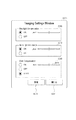
続いて、図8は、監視カメラ1000のImagingSettingsを設定するためのImagingSettings設定画面の一例を説明するための図である。この画面は、制御部2001により表示部2006に表示される。
Next, FIG. 8 is a diagram for explaining an example of an ImagingSettings setting screen for setting ImagingSettings of the
図8において、ImagingSettings設定画面8000は、WideDynamicRange設定パラメータ入力エリア8010と、DarkCompensation設定パラメータ入力エリア8020と、を含む。また、ImagingSettings設定画面8000は、BacklightCompensation設定パラメータ入力エリア8030と、設定ボタン8040と、閉じるボタン8041を含む。
In FIG. 8, the
なお、図8の画面では、BacklightCompensation設定パラメータ入力エリア8030は、WideDynamicRange設定パラメータ入力エリア8010よりも上に表示される。また、図8の画面では、WideDynamicRange設定パラメータ入力エリア8010は、DarkCompensation設定パラメータ入力エリア8020よりも上に表示される。
In the screen of FIG. 8, the Backlight Compensation setting
ここで、WideDynamicRange設定パラメータ入力エリア8010は、ON及びOFFの2つの選択肢から構成されるラジオボタン含む。ここで、本実施例において、このONに対応する選択肢は、WDR画像合成処理部1006を動作させることを示す合成動作選択肢に相当し、このOFFに対応する選択肢は、WDR画像合成処理部1006の動作を停止させることを示す合成停止選択肢に相当する。
Here, the WideDynamicRange setting
したがって、本実施例において、WideDynamicRange設定パラメータ入力エリア8010は、WDR画像合成処理部1006の動作に関する合成情報をユーザに入力させるための合成情報入力領域に相当する。
Therefore, in this embodiment, the WideDynamicRange setting
また、DarkCompensation設定パラメータ入力エリア8020は、ON、OFF、及びAUTOの3つの選択肢から構成されるラジオボタンを含む。ここで、本実施例において、このONに対応する選択肢は、暗部補正処理を動作させることを示す画像処理動作選択肢に相当し、このOFFに対応する選択肢は、暗部補正処理を停止させることを示す画像処理停止選択肢に相当する。
The Dark Compensation setting
さらに、このAUTOに対応する選択肢は、露出補正処理部1005の動作を監視カメラ1000に自動で制御させるための画像処理自動選択肢に相当する。したがって、本実施例において、DarkCompensation設定パラメータ入力エリア8020は、露出補正処理部1005の動作に関する画像処理情報をユーザに入力させるための画像処理情報入力領域に相当する。
Further, the option corresponding to AUTO corresponds to an automatic image processing option for causing the
そして、ユーザにより設定ボタン8040が押下された場合、クライアント装置2000は、ImagingSettings設定画面8000に設定された内容に応じたSetImagingSettingsのコマンド7000を監視カメラ1000に送信する。さらに、クライアント装置2000は、この送信とともに、ImagingSettings設定画面8000の表示を終了する。
When the
なお、本実施例におけるImagingSettings設定画面8000は、SetImagingSettingsコマンドに含まれるBLC、WDR、及びDCのそれぞれの値をユーザに入力させるためのユーザーインターフェースに相当する。
Note that the
また、ユーザにより閉じるボタン8041が押下された場合、クライアント装置2000は、SetImagingSettingsのコマンドを監視カメラ1000に送信することなく、ImagingSettings設定画面8000の表示を終了する。
When the
また、ここではDarkCompensationの設定をAUTOにしたため、Level設定用のバー8021がグレーアウトしている。
Here, since Dark Compensation is set to AUTO, the
図8のImagingSettings設定画面8000では、BacklightCompensation(7001)、WideDynamicRange(7002)、及びDarkCompensation(7003)の全てを有効にすることができる。
In the
このため、逆光補正処理、WDR処理、及び暗部補正処理が同時に動作してしまうことがあるので、撮像部1004から出力された撮像画像が明るくなり過ぎてしまうことがあった。そこで、本実施例では、DarkCompensation(7003)の設定値をAUTOにすることができるので、監視カメラ1000は、それぞれの処理を考慮した上での適切な暗部補正処理を行うことができる。
For this reason, the backlight correction process, the WDR process, and the dark part correction process may operate simultaneously, so that the captured image output from the
続いて、図9は、本実施例に係るクライアント装置2000における、SetImagingSettings設定画面表示処理を説明するためのフローチャートである。この処理は、監視カメラ1000からストリーミング配信される撮像画像に対する画像処理設定をクライアント装置2000のユーザが変更する際に、クライアント装置2000にて実行される処理である。
Next, FIG. 9 is a flowchart for explaining the SetImagingSettings setting screen display process in the
なお、この処理は、制御部2001により実行される。また、この処理の結果、クライアント装置2000の表示部2006には、図8の画面が表示されることとなる。
This process is executed by the
また、図8の画面には、ImagingSettingsのうち、WDR、DC、及びBCの値のみが設定可能に表示されているが、これに限られるものではない。例えば、図8の画面には、図6(a)乃至(e)に含まれる他のパラメータ(或いは全てのパラメータ)の値が設定可能に表示されていても良い。 Moreover, although only the values of WDR, DC, and BC of ImagingSettings are displayed on the screen of FIG. 8 so as to be settable, the present invention is not limited to this. For example, on the screen of FIG. 8, the values of other parameters (or all parameters) included in FIGS. 6A to 6E may be displayed so as to be settable.
図9におけるステップS9000では、制御部2001は、表示部2006に指示し、図8に示されるImagingSettings設定画面を表示させる。
In step S9000 in FIG. 9, the
ステップS9001では、制御部2001は、6052のトランザクションを実行することにより、監視カメラ1000からImagingSettingsのリストを取得する。そして、制御部2001は、取得したImagingSettingsのリストを記憶部2002に記憶させる。
In step S9001, the
なお、この取得したリストに含まれるImagingSettingsの数は、監視カメラが備える撮像部の数と同等であることが通常である。本実施例における監視カメラ1000は、1つの撮像部1004を備えているので、ステップS9001で取得されたリストに含まれるImagingSettingsの数は、1つであるが、この限りではない。
Note that the number of ImagingSettings included in the acquired list is usually equal to the number of imaging units included in the monitoring camera. Since the
例えば、監視カメラが複数の撮像部を備えているために、ステップS9001で取得されたリストに複数のImagingSettingsが含まれる場合も想定され得る。このような想定の場合は、これら複数のImagingSettingsの表示を切り替えるために、図8の画面内に複数のタブを設けても良い。 For example, since the surveillance camera includes a plurality of imaging units, a case where a plurality of ImagingSettings are included in the list acquired in step S9001 can be assumed. In such an assumption, a plurality of tabs may be provided in the screen of FIG. 8 in order to switch the display of the plurality of ImagingSettings.
また、これら複数のImagingSettingsのそれぞれに図8の画面が表示されるように構成しても良い。例えば、ステップS9001で取得されたリストに2つのImagingSettingsが含まれている場合には、2つのImagingSettingsのそれぞれのために、図8の画面を2つ表示するように構成しても良い。 Moreover, you may comprise so that the screen of FIG. 8 may be displayed on each of these several ImagingSettings. For example, when two ImagingSettings are included in the list acquired in step S9001, two screens in FIG. 8 may be displayed for each of the two ImagingSettings.
ステップS9002では、制御部2001は、6053のトランザクションを実行することにより、ImaginSettingsの各パラメータについて、監視カメラ1000が受け付け可能な選択肢等を監視カメラ1000から取得する。また、制御部2001は、取得した選択肢等を示す情報を記憶部2002に記憶させる。
In step S9002, the
ステップS9003では、制御部2001は、図8の画面を表示部2006に表示させる。ここで、制御部2001は、ステップS9001で得られたImagingSettingsに含まれるWDR、DC、及びBLCの設定値に応じ、図8の画面における、それぞれの設定値に対応するラジオボタンを選択された状態にする。
In step S9003, the
例えば、制御部2001は、記憶部2002に記憶されたImagingSettingsにおけるBacklightCompensationの設定パラメータの値を読み出す。次に、制御部2001は、読み出した値がON及びOFFのいずれであるのかを判定する。
For example, the
そして、制御部2001は、読み出した値がONであると判定した場合には、BacklightCompensation設定パラメータ入力エリア8030に含まれるラジオボタンのONに対応する選択肢を選択状態にする。
If the
一方、制御部2001は、読み出した値がOFFであると判定した場合には、BacklightCompensation設定パラメータ入力エリア8030に含まれるラジオボタンのOFFに対応する選択肢を選択状態にする。
On the other hand, when the
また、例えば、制御部2001は、記憶部2002に記憶されたImagingSettingsにおけるWideDynamicRangeの設定パラメータの値を読み出す。次に、制御部2001は、読み出した値がON及びOFFのいずれであるのかを判定する。
For example, the
そして、制御部2001は、読み出した値がONであると判定した場合には、WideDynamicRange設定パラメータ入力エリア8010に含まれるラジオボタンのONに対応する選択肢を選択状態にする。
If the
一方、制御部2001は、読み出した値がOFFであると判定した場合には、WideDynamicRange設定パラメータ入力エリア8010に含まれるラジオボタンのOFFに対応する選択肢を選択状態にする。
On the other hand, when the
また、例えば、制御部2001は、記憶部2002に記憶されたImagingSettingsにおけるDarkCompensationの設定パラメータの値を読み出す。次に、制御部2001は、読み出した値がON、OFF、及びAUTOのいずれであるのかを判定する。
Further, for example, the
そして、制御部2001は、読み出した値がONであると判定した場合には、DarkCompensation設定パラメータ入力エリア8020に含まれるラジオボタンのONに対応する選択肢を選択状態にする。
When the
一方、制御部2001は、読み出した値がOFFであると判定した場合には、DarkCompensation設定パラメータ入力エリア8020に含まれるラジオボタンのOFFに対応する選択肢を選択状態にする。
On the other hand, when the
或いは、制御部2001は、読み出した値がAUTOであると判定した場合には、DarkCompensation設定パラメータ入力エリア8020に含まれるラジオボタンのAUTOに対応する選択肢を選択状態にする。
Alternatively, when the
さらに、制御部2001は、ステップS9002で得られた選択肢の内容に基づき、図8の画面におけるラジオボタンのうち、監視カメラ1000が受け付け可能な選択肢以外のラジオボタンは、ユーザが選択することができないように表示させる。
Further, based on the contents of the options obtained in step S9002, the
なお、制御部2001は、WideDynamicRange設定パラメータ入力エリア8010のラジオボタンを入力可能に表示させた後、DarkCompensation設定パラメータ入力エリア8020のラジオボタンを入力可能に表示させても良い。
Note that the
ステップS9004では、制御部2001は、図8の画面におけるいずれかのボタンが押下されるまで、又は、6055のImagingSettings設定変更イベントを監視カメラ1000から受信するまで、待機する。
In step S9004, the
そして、制御部2001は、設定ボタン8040が押下されたと判定した場合には、ステップS9005に処理を進める。また、制御部2001は、閉じるボタン8041が押下されたと判定した場合には、ステップS9006に処理を進める。そして、制御部2001は、通信部2003により6055のImagingSettings設定変更イベントが受信された場合には、制御部2001は、ステップS9001に処理を戻す。
If the
ステップS9005では、制御部2001は、8010、8020、及び8030のそれぞれの入力エリアで選択されたラジオボタンに応じたパラメータを含むSetImaingSettingsコマンド7000を生成する。そして、制御部2001は、通信部2003に指示し、生成したSetImagingSettingsコマンドを、監視カメラ1000に送信させる。
In step S9005, the
つまり、この生成されたSetImagingSettigsコマンドには、WideDynamicRange設定パラメータ入力エリア8010のラジオボタンで選択された選択肢等に応じた値が記述される。同様に、この生成されたSetImagingSettigsコマンドには、DarkCompensation設定パラメータ入力エリア8020のラジオボタンで選択された選択肢等に応じた値が記述される。
That is, in the generated SetImagingSettings command, a value corresponding to an option selected by the radio button in the WideDynamicRange setting
また、同様に、この生成されたSetImagingSettingsコマンドには、BacklightCompensation設定パラメータ入力エリア8030のラジオボタンで選択された選択肢等に応じた値が記述される。
Similarly, in the generated SetImagingSettings command, a value corresponding to the option selected by the radio button in the BacklightCompensation setting
具体的には、クライアント装置2000は、図8の画面の設定内容で設定ボタン8040が押下された場合には、図7に示したSetImagingSettingsコマンドを、監視カメラ1000に送信する。
Specifically, when the
ステップS9006では、制御部2001は、表示部2006における図8の画面の表示を、終了させる。
In step S9006, the
以上のように、本実施例では、監視カメラ1000が受信するSetImagingSettingsコマンドには、WDRの設定パラメータとDCの設定パラメータとが記述され得る。
As described above, in this embodiment, the WDR setting parameter and the DC setting parameter can be described in the SetImagingSettings command received by the
ここで、このWDRの設定パラメータは、WDR処理を動作させるのか、このWDR処理を停止させるのかを択一的に示す。一方、このDCの設定パラメータは、露出補正処理部1005の暗部補正処理を動作させるのか、この暗部補正処理を停止させるのか、又はこの暗部補正処理の動作を監視カメラ1000に制御させるのかを択一的に示す。
Here, the WDR setting parameter alternatively indicates whether to operate the WDR process or to stop the WDR process. On the other hand, the DC setting parameter is used to select whether to operate the dark part correction process of the exposure
これにより、WDR処理を動作させる場合に、暗部補正処理を動作させるか否かを監視カメラ1000に自動で制御させることができる。このため、WDR処理及び暗部補正処理のそれぞれで撮像画像がどの程度明るくなるのかを考慮した上で、それぞれの動作を制御する必要性を減らすことができる。
Thereby, when operating the WDR process, the
また、本実施例におけるSetImagingSettingsコマンド、及びこのコマンドにおけるWDRの設定パラメータは、複数の監視カメラメーカーの間で標準化されたものである。 In addition, the SetImagingSettings command in this embodiment and the WDR setting parameter in this command are standardized among a plurality of surveillance camera manufacturers.
例えば、ONVIFは、SetImagingSettingsコマンドを、監視カメラの撮像処理及び画像処理を設定するための単一のコマンドとして標準化している。更に、ONVIFは、このコマンドにおけるWDRの設定パラメータには、ON及びOFFのいずれか一方の値が設定されるものとして標準化している。 For example, ONVIF standardizes the SetImagingSettings command as a single command for setting the imaging processing and image processing of the surveillance camera. Further, ONVIF standardizes that one of ON and OFF values is set in the WDR setting parameter in this command.
このようなSetImagingSettingsコマンドにDCの設定パラメータを新たに追加する場合、このDCの設定パラメータにはON、OFF、及びAUTOのいずれか1つの値が設定されるものとすることは、非常に有効である。 When a DC setting parameter is newly added to such a SetImagingSettings command, it is very effective to set any one of ON, OFF, and AUTO to this DC setting parameter. is there.
なぜならば、WDR処理及び暗部補正処理のそれぞれの効果は、監視カメラメーカー毎に異なっており、撮像部1004から出力された撮像画像が暗過ぎることなく且つ明る過ぎることなく、それぞれの処理の動作を制御することは、極めて難しいからである。
This is because the effects of the WDR process and the dark part correction process are different for each surveillance camera manufacturer, and the operation of each process is performed without the captured image output from the
そこで、本実施例のように、DCの設定パラメータに設定される値としてAUTOを新たに設けることで、暗部補正処理の動作を監視カメラ1000に自動で制御させることが可能となる。これにより、撮像部1004から出力された撮像画像が暗過ぎてしまったり、明る過ぎてしまったりすることを防止することができる。
Therefore, as in the present embodiment, by newly providing AUTO as a value set in the DC setting parameter, it is possible to cause the
さらに、これは、所定の監視領域を監視する監視カメラでは、特に有効である。具体的には、監視領域の撮像画像は、有事の際の証拠となる重要な情報である。このため、監視カメラのWDR処理及び暗部補正処理のそれぞれの動作を適切に設定することができず、監視領域の撮像画像に白飛びが発生したりや黒つぶれが残ったりしてしまうことは、許されないからである。 Furthermore, this is particularly effective in a monitoring camera that monitors a predetermined monitoring area. Specifically, the captured image of the monitoring area is important information that becomes evidence in the event of an emergency. For this reason, it is not possible to appropriately set the operations of the WDR process and the dark part correction process of the surveillance camera, and it is allowed that the captured image of the surveillance area is overexposed or the blackout remains. Because it is not done.
以上、本実施例の効果は、WDR処理と暗部補正処理との関係で述べられているが、本実施例の効果は、逆光補正処理と暗部補正処理との関係でも、逆光補正処理とWDR補正処理と暗部補正処理との関係でも同様である。 As described above, the effect of the present embodiment is described in relation to the WDR processing and the dark portion correction processing. However, the effect of the present embodiment is also related to the backlight correction processing and the WDR correction in the relationship between the backlight correction processing and the dark portion correction processing. The same applies to the relationship between the processing and the dark portion correction processing.
また、本実施例におけるSetImagingSettingsコマンドは、WideDynamicRange(7002)の設定パラメータの後に、DarkCompensation(7003)の設定パラメータが記述される。 In the SetImagingSettings command according to the present embodiment, the setting parameter of DarkCompensation (7003) is described after the setting parameter of WideDynamicRange (7002).
これにより、WideDynamicRange(7002)の設定パラメータの設定の結果に応じ、DarkCompensation(7003)の設定パラメータを設定することができる。例えば、WideDynamicRange(7003)の設定パラメータのModeの値がONに設定されたことに応じ、DarkComepnsation(7003)の設定パラメータのModeの値をAUTOに設定することができる。 Thereby, the setting parameter of DarkCompensation (7003) can be set according to the setting result of the setting parameter of WideDynamicRange (7002). For example, in response to the Mode parameter value of WideDynamicRange (7003) being set to ON, the Mode parameter value of DarkComposition (7003) can be set to AUTO.
この結果、WideDynamicRange(7002)の設定パラメータを確認した上で、WideDynamicRange(7003)の設定パラメータを設定するという、スムーズなパラメータの設定を実現することができる。 As a result, it is possible to realize a smooth parameter setting in which the setting parameter of the Wide Dynamic Range (7003) is set after confirming the setting parameter of the Wide Dynamic Range (7002).
この点については、BacklightCompensation(7001)の設定パラメータとDarkComepnsation(7003)との設定パラメータとの関係でも、同様である。 The same applies to the relationship between the setting parameter of BacklightCompensation (7001) and the setting parameter of DarkCombination (7003).
また、本実施例では、BC、WDR、DCの設定値を送信したが、それぞれ省略することができる。また、BC、WDRにLevelを設定していたが、省略することができる。 In this embodiment, the setting values of BC, WDR, and DC are transmitted, but can be omitted. Moreover, although Level was set to BC and WDR, it can be omitted.
また、本実施例では、露出補正処理部1005の暗部補正処理を設定するためのパラメータを「DarkCompensation」と称したが、これに限られるものではない。「DarkCompensation」の代わりに「DarknessCompensation」と称しても良い。或いは、「DarkCompensation」の代わりに「Delighting」と称しても良い。
In this embodiment, the parameter for setting the dark portion correction process of the exposure
また、本実施例における露出補正処理部1005は、複数の処理ブロックで構成されても良く、この際、逆光補正処理を実行する処理ブロックと暗部補正処理を実行する処理ブロックとは、必ずしも同じ処理ブロックである必要は無い。例えば、露出補正処理部1005に含まれる2つの処理ブロックのうち、一方を逆光補正処理が実行される処理ブロックとし、他方を暗部補正処理が実行される処理ブロックとしても良い。
In addition, the exposure
この場合、逆光補正処理が実行される処理ブロックは、撮像画像を画像処理で明るくする第1の画像処理部に相当し、暗部補正処理が実行される処理ブロックは、撮像画像をこの画像処理とは異なる画像処理で明るくする第2の画像処理部に相当する。 In this case, the processing block in which the backlight correction processing is executed corresponds to a first image processing unit that brightens the captured image by image processing, and the processing block in which the dark portion correction processing is executed includes the captured image as image processing. Corresponds to a second image processing unit that brightens by different image processing.
また、本実施例におけるステップS9004では、制御部2001は、WideDynamicRange設定パラメータ入力エリア8010のラジオボタンのONに対応する選択肢が選択されたか否かを判定しても良い。
In step S9004 according to the present embodiment, the
さらに、制御部2001は、このONに対応する選択肢が選択されたと判定した場合には、DarkCompensation設定パラメータ入力エリア8020のラジオボタンのAUTOに対応する選択肢を選択状態にしても良い。
Furthermore, if the
その上、制御部2001は、WideDynamicRange設定パラメータ入力エリア8010のラジオボタンのOFFに対応する選択肢が選択されたか否かを判定しても良い。
In addition, the
なおかつ、制御部2001は、このOFFに対応する選択肢が選択されたと判定した場合には、DarkCompensation設定パラメータ入力エリア8020のラジオボタンのONに対応する選択肢を選択状態にしても良い。
If the
また、本実施例におけるステップS9004では、制御部2001は、BacklightCompensation設定パラメータ入力エリア8030のラジオボタンのONに対応する選択肢が選択されたか否かを判定しても良い。
In step S9004 in the present embodiment, the
さらに、制御部2001は、このONに対応する選択肢が選択されたと判定した場合には、DarkCompensation設定パラメータ入力エリア8020のラジオボタンのAUTOに対応する選択肢を選択状態にしても良い。
Furthermore, if the
その上、制御部2001は、BacklightCompensation設定パラメータ入力エリア8030のラジオボタンのOFFに対応する選択肢が選択されたか否かを判定しても良い。
In addition, the
なおかつ、制御部2001は、このOFFに対応する選択肢が選択されたと判定した場合には、DarkCompensation設定パラメータ入力エリア8020のラジオボタンのONに対応する選択肢を選択状態にしても良い。
If the
また、本実施例におけるステップS9004では、制御部2001は、表示部2006において、まず、BacklightCompensation設定パラメータ入力エリア8030だけを表示させてもよい。さらに、この表示の後、制御部2001は、このエリアでパラメータが入力されたと判定した場合には、表示部2006において、WideDynamicRange設定パラメータ入力エリア8010を表示させても良い。
In step S9004 in the present embodiment, the
なおかつ、この表示の後、制御部2001は、表示部2006において、DarkCompensation設定パラメータ入力エリア8020を表示させても良い。
In addition, after this display, the
これにより、表示部2006において、BacklightCompensation設定パラメータ入力エリア8030が表示された後、WideDynamicRange設定パラメータ入力エリア8010が表示される。また、表示部2006において、WideDynamicRange設定パラメータ入力エリア8010が表示された後、DarkCompensation設定パラメータ入力エリア8020が表示される。
Accordingly, after the Backlight Compensation setting
また、本実施例におけるステップS9004では、制御部2001は、表示部2006において、まず、BacklightCompensation設定パラメータ入力エリア8030だけを入力可能に表示させてもよい。さらに、この表示の後、制御部2001は、BacklightCompensation設定パラメータ入力エリア8030でパラメータが入力されたか否かを判定しても良い。
Further, in step S9004 in the present embodiment, the
この判定の結果、制御部2001は、このエリアでパラメータが入力されたと判定した場合には、表示部2006において、WideDynamicRange設定パラメータ入力エリア8010を入力可能に表示させても良い。なおかつ、この表示の後、制御部2001は、WideDynamicRange設定パラメータ入力エリア8010でパラメータが入力されたか否かを判定しても良い。
As a result of this determination, if the
この判定の結果、制御部2001は、このエリアでパラメータが入力されたと判定した場合には、表示部2006において、DarkCompensation設定パラメータ入力エリア8020を入力可能に表示させても良い。
As a result of this determination, if the
これにより、表示部2006において、BacklightCompensation設定パラメータ入力エリア8030が入力可能に表示された後、WideDynamicRange設定パラメータ入力エリア8010が入力可能に表示される。また、表示部2006において、WideDynamicRange設定パラメータ入力エリア8010が入力可能に表示された後、DarkCompensation設定パラメータ入力エリア8020が入力可能に表示される。
As a result, after the Backlight Compensation setting
また、本実施例では、撮像部1004から出力された1枚の撮像画像を用い、この1枚の撮像画像を明るくする処理として、逆光補正処理及び暗部補正処理を用いたが、これに限られるものではない。例えば、逆光補正処理及び暗部補正処理のいずれか一方の代わりに、撮像部1004から出力された1枚の撮像画像の該当する画素周辺の画素同士を加算することで、この撮像画像を明るくする画素加算処理を用いても良い。
Further, in the present embodiment, a single captured image output from the
また、本実施例において、BacklightCompensation(7001)の設定パラメータのLevelの値の範囲は、DarkCompensation(7003)の設定パラメータのLevelの値の範囲よりも広くしても良い。 In this embodiment, the range of the Level value of the setting parameter of Backlight Compensation (7001) may be wider than the range of the Level value of the setting parameter of Dark Compensation (7003).
同様に、WideDynamicRange(7002)の設定パラメータのLevelの値の範囲も、DarkCompensation(7003)の設定パラメータのLevelの値の範囲よりも広くしても良い。 Similarly, the range of the Level value of the setting parameter of WideDynamicRange (7002) may be wider than the range of the Level value of the setting parameter of DarkCompensation (7003).
(その他の実施例)
また、本発明は、以下の処理を実行することによっても実現される。即ち、上述した実施例の機能を実現するソフトウエア(プログラム)を、ネットワーク又は各種記憶媒体を介してシステム或いは装置に提供し、そのシステム或いは装置のコンピュータ(またはCPUやMPU等)がプログラムを読み出して実行する処理である。
(Other examples)
The present invention can also be realized by executing the following processing. That is, software (program) that realizes the functions of the above-described embodiments is provided to a system or apparatus via a network or various storage media, and the computer (or CPU, MPU, etc.) of the system or apparatus reads the program. To be executed.
以上、本発明の好ましい実施例について説明したが、本発明はこれらの実施例に限定されず、その要旨の範囲内で種々の変形及び変更が可能である。 As mentioned above, although the preferable Example of this invention was described, this invention is not limited to these Examples, A various deformation | transformation and change are possible within the range of the summary.
1000 監視カメラ
1003 通信部
1004 撮像部
1005 露出補正処理部
1006 WDR画像合成処理部
2000 クライアント装置
1000
Claims (12)
撮像手段と、
前記撮像手段から出力された撮像画像の明るさを第一の画像処理を実行することにより変化させる第一の画像処理手段と、
前記撮像手段から出力された撮像画像の明るさを前記第一の画像処理とは異なる第二の画像処理を実行することにより変化させる第二の画像処理手段と、
前記第一の画像処理を制御するための第一の画像処理情報または前記第二の画像処理を制御するための第二の画像処理情報を含むコマンドを、前記クライアント装置からネットワークを介して受信する受信手段と、
前記受信手段で受信されたコマンドに基づき、前記第一の画像処理または前記第二の画像処理を制御する制御手段と、
を備え、
前記第一の画像処理情報は、少なくとも前記第一の画像処理を実行させるか否かを示す情報を含み、
前記第二の画像処理情報は、少なくとも前記第二の画像処理を実行させることを示す情報、前記第二の画像処理を実行させないことを示す情報、及び前記第二の画像処理を実行させるか否かを前記撮像装置が自動で判断することを示す情報、のいずれかを含むことを特徴とする撮像装置。 An imaging device that communicates with a client device via a network,
Imaging means;
A first image processing means for changing by performing the brightness of the first image processing captured image output from the image pickup means,
Second image processing means for changing brightness of a captured image output from the imaging means by executing second image processing different from the first image processing;
A command including first image processing information for controlling the first image processing or second image processing information for controlling the second image processing is received from the client device via a network. Receiving means;
Control means for controlling the first image processing or the second image processing based on a command received by the receiving means;
With
The first image processing information includes at least information indicating whether or not to execute the first image processing,
It said second image processing information are whether or not to perform at least the second information indicating that causes execute image processing, the second information indicating that not execute the image processing, and the second image processing information indicating that the imaging apparatus automatically determines whether an imaging apparatus characterized by comprising any of.
前記第二の画像処理手段は、前記撮像手段から出力された1枚の撮像画像の明るさを前記第二の画像処理で変化させること特徴とする請求項1に記載の撮像装置。 The first image processing means changes the brightness of the captured image output from the imaging means by combining the plurality of captured images output from the imaging means by the first image processing ,
The imaging apparatus according to claim 1, wherein the second image processing unit changes the brightness of one captured image output from the imaging unit by the second image processing.
前記第一の画像処理を制御するための第一の画像処理情報または前記第二の画像処理を制御するための第二の画像処理情報とを含むコマンドを、前記クライアント装置からネットワークを介して送信する送信手段
を備え、
前記第一の画像処理情報は、少なくとも前記第一の画像処理を実行させるか否かを示す情報を含み、
前記第二の画像処理情報は、少なくとも前記第二の画像処理を実行させることを示す情報、前記第二の画像処理を実行させないことを示す情報、及び前記第二の画像処理を実行させるか否かを前記撮像装置が自動で判断することを示す情報、のいずれかを含むことを特徴とするクライアント装置。 Wherein the brightness of the captured image output from the imaging unit and the first image processing section that changes by performing the first image processing the brightness of the imaged image output from the imaging unit imaging unit first An imaging device having a second image processing unit that is changed by executing a second image processing different from the one image processing, and a client device that communicates via a network,
A command including first image processing information for controlling the first image processing or second image processing information for controlling the second image processing is transmitted from the client device via a network. Transmission means for
The first image processing information includes at least information indicating whether or not to execute the first image processing,
It said second image processing information are whether or not to perform at least the second information indicating that causes execute image processing, the second information indicating that not execute the image processing, and the second image processing information indicating that the imaging apparatus automatically determines whether a client apparatus characterized by comprising any of.
前記コマンドは、前記ユーザーインターフェース手段で入力された第一画像処理情報または第二画像処理情報を含むことを特徴とする請求項6に記載のクライアント装置。 User interface means for allowing the user to input the first image processing information and the second image processing information;
The client device according to claim 6 , wherein the command includes first image processing information or second image processing information input by the user interface unit.
前記第二の画像処理情報入力領域は、前記第二の画像処理を実行させることを示す選択肢と、前記第二の画像処理を実行させないことを示す選択肢と、前記第二の画像処理を実行させるか否かを前記撮像装置に自動で判断させることを示す選択肢と、を含み、
前記ユーザーインターフェース手段は、前記第一の画像処理を実行させることを示す選択肢が選択されている場合に、前記第二の画像処理を実行させるか否かを前記撮像装置に自動で判断させることを示す選択肢を選択状態にすることを特徴とする請求項8に記載のクライアント装置。 The first image processing information input area may include a choice indicating to execute the first image processing, and a selection indicating that not execute the first image processing,
Said second image processing information input area, the execution and choice indicating to perform the second image processing, the option indicating that not execute the second image processing, the second image processing Including an option indicating that the imaging apparatus automatically determines whether or not to perform,
It said user interface means, when the option indicating to execute the first image processing is selected, that is determining whether to execute the second image processing automatically to said image pickup device The client apparatus according to claim 8 , wherein an option to be displayed is selected.
前記第一の画像処理を制御するための第一の画像処理情報または前記第二の画像処理を制御するための第二の画像処理情報を含むコマンドを、前記クライアント装置からネットワークを介して受信する受信ステップと、
前記受信ステップで受信されたコマンドに基づき、前記第一の画像処理または前記第二の画像処理を制御する制御ステップと、
を備え、
前記第一の画像処理情報は、少なくとも前記第一の画像処理を実行させるか否かを示す情報を含み、
前記第二の画像処理情報は、少なくとも前記第二の画像処理を実行させることを示す情報、前記第二の画像処理を実行させないことを示す情報、及び前記第二の画像処理を実行させるか否かを前記撮像装置が自動で判断することを示す情報のいずれかを含むことを特徴とする撮像装置の制御方法。 An imaging unit, a first image processing unit that changes by performing the brightness of the first image processing captured image output from the imaging unit, the brightness of the captured image output from the imaging unit A second image processing unit that changes by executing second image processing different from the first image processing, and a method for controlling an imaging device that communicates with a client device via a network,
A command including first image processing information for controlling the first image processing or second image processing information for controlling the second image processing is received from the client device via a network. Receiving step;
A control step for controlling the first image processing or the second image processing based on the command received in the reception step;
With
The first image processing information includes at least information indicating whether or not to execute the first image processing,
It said second image processing information are whether or not to perform at least the second information indicating that causes execute image processing, the second information indicating that not execute the image processing, and the second image processing control method for an imaging apparatus characterized by comprising any of the information indicating that the imaging apparatus is determined automatically whether.
前記第一の画像処理を制御するための第一の画像処理情報または前記第二の画像処理を制御するための第二の画像処理情報を含むコマンドを、前記クライアント装置からネットワークを介して送信する送信ステップと、
を備え、
前記第一の画像処理情報は、少なくとも前記第一の画像処理を実行させるか否かの情報を含み、
前記第二の画像処理情報は、少なくとも前記第二の画像処理を実行させることを示す情報、前記第二の画像処理を実行させないことを示す情報、及び前記第二の画像処理を実行させるか否かを前記撮像装置が自動で判断することを示す情報、のいずれかを含むことを特徴とするクライアント装置の制御方法。 The first image processing unit that changes the brightness of the captured image output from the imaging unit and the captured image unit by the first image processing, and the brightness of the captured image output from the imaging unit is the first image processing. A control method of an imaging apparatus having a second image processing unit that is changed by second image processing different from the above and a client apparatus that communicates via a network,
A command including first image processing information for controlling the first image processing or second image processing information for controlling the second image processing is transmitted from the client device via a network. Sending step;
With
The first image processing information includes at least information on whether or not to execute the first image processing,
It said second image processing information are whether or not to perform at least the second information indicating that causes execute image processing, the second information indicating that not execute the image processing, and the second image processing control method for a client device, characterized in that it comprises information indicating that the imaging apparatus automatically determines whether the one of.
Priority Applications (12)
| Application Number | Priority Date | Filing Date | Title |
|---|---|---|---|
| JP2013234250A JP6415037B2 (en) | 2013-11-12 | 2013-11-12 | IMAGING DEVICE, CLIENT DEVICE, IMAGING DEVICE CONTROL METHOD, CLIENT DEVICE CONTROL METHOD, AND PROGRAM |
| PCT/JP2014/005600 WO2015072117A1 (en) | 2013-11-12 | 2014-11-07 | Imaging apparatus, external apparatus, imaging system, control method for imaging apparatus, control method for external apparatus, control method for imaging system, and program |
| KR1020167015151A KR101771406B1 (en) | 2013-11-12 | 2014-11-07 | Imaging apparatus, external apparatus, imaging system, control method for imaging apparatus, control method for external apparatus, control method for imaging system, and program |
| KR1020177022917A KR101839423B1 (en) | 2013-11-12 | 2014-11-07 | Imaging apparatus, external apparatus, imaging system, control method for imaging apparatus, control method for external apparatus, program, and storage medium |
| US15/035,462 US9826137B2 (en) | 2013-11-12 | 2014-11-07 | Imaging apparatus, external apparatus, imaging system, control method for imaging apparatus, control method for external apparatus, control method for imaging system, and program |
| BR112016007615A BR112016007615A2 (en) | 2013-11-12 | 2014-11-07 | imaging device, external device, imaging system, control method for imaging device, control method for external device, control method for imaging system and program |
| RU2016123006A RU2646935C2 (en) | 2013-11-12 | 2014-11-07 | Imaging device, external device, imaging system, control method for imaging device, control method for external device, control method for imaging system and programme |
| CN201480062048.3A CN105723695B (en) | 2013-11-12 | 2014-11-07 | Picture pick-up device, external equipment, camera system and its control method |
| EP14862566.8A EP3069504B1 (en) | 2013-11-12 | 2014-11-07 | Imaging apparatus, external apparatus, control method for imaging apparatus, control method for external apparatus and programs |
| KR1020187007049A KR101906938B1 (en) | 2013-11-12 | 2014-11-07 | Imaging apparatus, image processing control apparatus, control method for imaging apparatus, control method for image processing control apparatus |
| CN201910220135.1A CN110062154B (en) | 2013-11-12 | 2014-11-07 | Image capturing apparatus, image processing control apparatus, control method therefor, and storage medium |
| US15/789,837 US10148860B2 (en) | 2013-11-12 | 2017-10-20 | Imaging apparatus, external apparatus, imaging system, control method for imaging apparatus, control method for external apparatus, control method for imaging system, and program |
Applications Claiming Priority (1)
| Application Number | Priority Date | Filing Date | Title |
|---|---|---|---|
| JP2013234250A JP6415037B2 (en) | 2013-11-12 | 2013-11-12 | IMAGING DEVICE, CLIENT DEVICE, IMAGING DEVICE CONTROL METHOD, CLIENT DEVICE CONTROL METHOD, AND PROGRAM |
Publications (3)
| Publication Number | Publication Date |
|---|---|
| JP2015095765A JP2015095765A (en) | 2015-05-18 |
| JP2015095765A5 JP2015095765A5 (en) | 2016-12-28 |
| JP6415037B2 true JP6415037B2 (en) | 2018-10-31 |
Family
ID=53057069
Family Applications (1)
| Application Number | Title | Priority Date | Filing Date |
|---|---|---|---|
| JP2013234250A Active JP6415037B2 (en) | 2013-11-12 | 2013-11-12 | IMAGING DEVICE, CLIENT DEVICE, IMAGING DEVICE CONTROL METHOD, CLIENT DEVICE CONTROL METHOD, AND PROGRAM |
Country Status (8)
| Country | Link |
|---|---|
| US (2) | US9826137B2 (en) |
| EP (1) | EP3069504B1 (en) |
| JP (1) | JP6415037B2 (en) |
| KR (3) | KR101771406B1 (en) |
| CN (2) | CN110062154B (en) |
| BR (1) | BR112016007615A2 (en) |
| RU (1) | RU2646935C2 (en) |
| WO (1) | WO2015072117A1 (en) |
Families Citing this family (12)
| Publication number | Priority date | Publication date | Assignee | Title |
|---|---|---|---|---|
| JP6234165B2 (en) * | 2013-10-28 | 2017-11-22 | キヤノン株式会社 | IMAGING DEVICE, EXTERNAL DEVICE, IMAGING SYSTEM, IMAGING DEVICE CONTROL METHOD, EXTERNAL DEVICE CONTROL METHOD, IMAGING SYSTEM CONTROL METHOD, AND PROGRAM |
| JP6415037B2 (en) | 2013-11-12 | 2018-10-31 | キヤノン株式会社 | IMAGING DEVICE, CLIENT DEVICE, IMAGING DEVICE CONTROL METHOD, CLIENT DEVICE CONTROL METHOD, AND PROGRAM |
| CN107873054B (en) | 2014-09-09 | 2022-07-12 | 博德研究所 | Droplet-based methods and apparatus for multiplexed single-cell nucleic acid analysis |
| EP3268462B1 (en) | 2015-03-11 | 2021-08-11 | The Broad Institute, Inc. | Genotype and phenotype coupling |
| WO2017075297A1 (en) | 2015-10-28 | 2017-05-04 | The Broad Institute Inc. | High-throughput dynamic reagent delivery system |
| WO2017075265A1 (en) | 2015-10-28 | 2017-05-04 | The Broad Institute, Inc. | Multiplex analysis of single cell constituents |
| JP6786253B2 (en) * | 2016-04-15 | 2020-11-18 | キヤノン株式会社 | Imaging system, information processing device, control method of imaging system, control method of information processing device, and program |
| US10742866B2 (en) * | 2016-09-30 | 2020-08-11 | Microsoft Technology Licensing, Llc | Universal serial bus (USB) video extension |
| CN113206959B (en) * | 2016-11-01 | 2024-01-09 | 斯纳普公司 | Method and server for determining automatic enclosure configuration |
| DE102016120845B4 (en) * | 2016-11-02 | 2018-10-11 | Matrix Vision Gmbh Bildverarbeitung | Camera system and operating method for this |
| US11072816B2 (en) | 2017-05-03 | 2021-07-27 | The Broad Institute, Inc. | Single-cell proteomic assay using aptamers |
| JP6968610B2 (en) * | 2017-08-01 | 2021-11-17 | キヤノン株式会社 | Imaging equipment, information processing methods and programs |
Family Cites Families (20)
| Publication number | Priority date | Publication date | Assignee | Title |
|---|---|---|---|---|
| JP4282113B2 (en) | 1998-07-24 | 2009-06-17 | オリンパス株式会社 | IMAGING DEVICE, IMAGING METHOD, AND RECORDING MEDIUM CONTAINING IMAGING PROGRAM |
| JP4277452B2 (en) * | 2000-02-25 | 2009-06-10 | ソニー株式会社 | Recording device, playback device |
| JP4544756B2 (en) * | 2001-01-19 | 2010-09-15 | オリンパス株式会社 | Imaging device |
| US20030093805A1 (en) | 2001-11-15 | 2003-05-15 | Gin J.M. Jack | Dual camera surveillance and control system |
| JP4224346B2 (en) * | 2003-05-15 | 2009-02-12 | 富士フイルム株式会社 | Imaging method and apparatus |
| US7492390B2 (en) * | 2003-07-14 | 2009-02-17 | Arecont Vision, Llc. | Dual spectral band network camera |
| JP2006074227A (en) | 2004-08-31 | 2006-03-16 | Canon Inc | Monitoring camera, monitoring system, method for controlling monitoring camera, receiver, and method for controlling receiver |
| JP4391915B2 (en) * | 2004-09-15 | 2009-12-24 | 株式会社エルモ社 | Surveillance camera device |
| US7206136B2 (en) * | 2005-02-18 | 2007-04-17 | Eastman Kodak Company | Digital camera using multiple lenses and image sensors to provide an extended zoom range |
| JP4423678B2 (en) * | 2006-09-06 | 2010-03-03 | カシオ計算機株式会社 | Imaging apparatus, imaging method, and program |
| JP2008211413A (en) * | 2007-02-26 | 2008-09-11 | Sanyo Electric Co Ltd | Video camera device |
| JP4306752B2 (en) * | 2007-03-19 | 2009-08-05 | ソニー株式会社 | Imaging device, photometry method, luminance calculation method, program |
| JP4424403B2 (en) | 2007-09-28 | 2010-03-03 | ソニー株式会社 | Imaging apparatus, imaging method, and imaging program |
| JP4661922B2 (en) * | 2008-09-03 | 2011-03-30 | ソニー株式会社 | Image processing apparatus, imaging apparatus, solid-state imaging device, image processing method, and program |
| JP4770907B2 (en) | 2008-10-21 | 2011-09-14 | ソニー株式会社 | Imaging apparatus, imaging method, and program |
| JP5214538B2 (en) | 2009-05-25 | 2013-06-19 | オリンパス株式会社 | Image acquisition apparatus, image composition method, and microscope system |
| CN102469248B (en) * | 2010-11-12 | 2016-03-02 | 华晶科技股份有限公司 | Device for filming image and image synthesis method thereof |
| JP5316625B2 (en) * | 2011-11-11 | 2013-10-16 | カシオ計算機株式会社 | Image composition apparatus and program |
| JP5898509B2 (en) * | 2012-01-31 | 2016-04-06 | キヤノン株式会社 | Imaging apparatus, control method therefor, program, and storage medium |
| JP6415037B2 (en) * | 2013-11-12 | 2018-10-31 | キヤノン株式会社 | IMAGING DEVICE, CLIENT DEVICE, IMAGING DEVICE CONTROL METHOD, CLIENT DEVICE CONTROL METHOD, AND PROGRAM |
-
2013
- 2013-11-12 JP JP2013234250A patent/JP6415037B2/en active Active
-
2014
- 2014-11-07 EP EP14862566.8A patent/EP3069504B1/en active Active
- 2014-11-07 US US15/035,462 patent/US9826137B2/en active Active
- 2014-11-07 WO PCT/JP2014/005600 patent/WO2015072117A1/en active Application Filing
- 2014-11-07 BR BR112016007615A patent/BR112016007615A2/en not_active Application Discontinuation
- 2014-11-07 RU RU2016123006A patent/RU2646935C2/en active
- 2014-11-07 KR KR1020167015151A patent/KR101771406B1/en active IP Right Grant
- 2014-11-07 KR KR1020187007049A patent/KR101906938B1/en active IP Right Grant
- 2014-11-07 CN CN201910220135.1A patent/CN110062154B/en active Active
- 2014-11-07 CN CN201480062048.3A patent/CN105723695B/en active Active
- 2014-11-07 KR KR1020177022917A patent/KR101839423B1/en active IP Right Grant
-
2017
- 2017-10-20 US US15/789,837 patent/US10148860B2/en active Active
Also Published As
| Publication number | Publication date |
|---|---|
| US10148860B2 (en) | 2018-12-04 |
| US20180041687A1 (en) | 2018-02-08 |
| CN105723695A (en) | 2016-06-29 |
| CN105723695B (en) | 2019-04-02 |
| EP3069504A4 (en) | 2017-07-26 |
| JP2015095765A (en) | 2015-05-18 |
| US20160295093A1 (en) | 2016-10-06 |
| US9826137B2 (en) | 2017-11-21 |
| WO2015072117A1 (en) | 2015-05-21 |
| KR20180030252A (en) | 2018-03-21 |
| KR20170098963A (en) | 2017-08-30 |
| RU2016123006A (en) | 2017-12-19 |
| BR112016007615A2 (en) | 2017-08-01 |
| CN110062154A (en) | 2019-07-26 |
| RU2646935C2 (en) | 2018-03-13 |
| KR101771406B1 (en) | 2017-08-25 |
| KR20160082596A (en) | 2016-07-08 |
| CN110062154B (en) | 2021-01-05 |
| KR101906938B1 (en) | 2018-10-11 |
| EP3069504B1 (en) | 2022-01-05 |
| KR101839423B1 (en) | 2018-03-16 |
| EP3069504A1 (en) | 2016-09-21 |
Similar Documents
| Publication | Publication Date | Title |
|---|---|---|
| JP6415037B2 (en) | IMAGING DEVICE, CLIENT DEVICE, IMAGING DEVICE CONTROL METHOD, CLIENT DEVICE CONTROL METHOD, AND PROGRAM | |
| US20150116489A1 (en) | Imaging apparatus | |
| JP6444073B2 (en) | Image processing device | |
| JP6234165B2 (en) | IMAGING DEVICE, EXTERNAL DEVICE, IMAGING SYSTEM, IMAGING DEVICE CONTROL METHOD, EXTERNAL DEVICE CONTROL METHOD, IMAGING SYSTEM CONTROL METHOD, AND PROGRAM | |
| US10063759B2 (en) | Image pickup apparatus, image capturing system, method of controlling image pickup apparatus, method of controlling image capturing system, and program | |
| JP6253307B2 (en) | IMAGING DEVICE, EXTERNAL DEVICE, IMAGING SYSTEM, IMAGING DEVICE CONTROL METHOD, EXTERNAL DEVICE CONTROL METHOD, IMAGING SYSTEM CONTROL METHOD, AND PROGRAM | |
| JP2015088786A (en) | Imaging apparatus, imaging system, control method of imaging apparatus, control method of imaging system, and program | |
| JP6444473B2 (en) | IMAGING DEVICE, EXTERNAL DEVICE, IMAGING SYSTEM, IMAGING DEVICE CONTROL METHOD, EXTERNAL DEVICE CONTROL METHOD, IMAGING SYSTEM CONTROL METHOD, AND PROGRAM | |
| US10313614B2 (en) | Image processing apparatus | |
| JP6270526B2 (en) | Imaging apparatus and imaging system | |
| JP6444036B2 (en) | Imaging apparatus and imaging system | |
| JP2015220722A (en) | Imaging apparatus and external apparatus | |
| JP2015041960A (en) | Imaging device, external device, imaging system, imaging device control method, external device control method, imaging system control method, and program |
Legal Events
| Date | Code | Title | Description |
|---|---|---|---|
| A521 | Request for written amendment filed |
Free format text: JAPANESE INTERMEDIATE CODE: A523 Effective date: 20161111 |
|
| A621 | Written request for application examination |
Free format text: JAPANESE INTERMEDIATE CODE: A621 Effective date: 20161111 |
|
| A131 | Notification of reasons for refusal |
Free format text: JAPANESE INTERMEDIATE CODE: A131 Effective date: 20180109 |
|
| A521 | Request for written amendment filed |
Free format text: JAPANESE INTERMEDIATE CODE: A523 Effective date: 20180312 |
|
| TRDD | Decision of grant or rejection written | ||
| A01 | Written decision to grant a patent or to grant a registration (utility model) |
Free format text: JAPANESE INTERMEDIATE CODE: A01 Effective date: 20180904 |
|
| A61 | First payment of annual fees (during grant procedure) |
Free format text: JAPANESE INTERMEDIATE CODE: A61 Effective date: 20181002 |
|
| R151 | Written notification of patent or utility model registration |
Ref document number: 6415037 Country of ref document: JP Free format text: JAPANESE INTERMEDIATE CODE: R151 |