JP6414397B2 - Power line communication system and master communication device - Google Patents
Power line communication system and master communication device Download PDFInfo
- Publication number
- JP6414397B2 JP6414397B2 JP2014131348A JP2014131348A JP6414397B2 JP 6414397 B2 JP6414397 B2 JP 6414397B2 JP 2014131348 A JP2014131348 A JP 2014131348A JP 2014131348 A JP2014131348 A JP 2014131348A JP 6414397 B2 JP6414397 B2 JP 6414397B2
- Authority
- JP
- Japan
- Prior art keywords
- master
- power line
- side transmission
- communication device
- slave
- Prior art date
- Legal status (The legal status is an assumption and is not a legal conclusion. Google has not performed a legal analysis and makes no representation as to the accuracy of the status listed.)
- Expired - Fee Related
Links
Images


Classifications
-
- H—ELECTRICITY
- H04—ELECTRIC COMMUNICATION TECHNIQUE
- H04L—TRANSMISSION OF DIGITAL INFORMATION, e.g. TELEGRAPHIC COMMUNICATION
- H04L25/00—Baseband systems
- H04L25/02—Details ; arrangements for supplying electrical power along data transmission lines
- H04L25/0264—Arrangements for coupling to transmission lines
- H04L25/0272—Arrangements for coupling to multiple lines, e.g. for differential transmission
-
- H—ELECTRICITY
- H04—ELECTRIC COMMUNICATION TECHNIQUE
- H04B—TRANSMISSION
- H04B3/00—Line transmission systems
- H04B3/54—Systems for transmission via power distribution lines
-
- H—ELECTRICITY
- H04—ELECTRIC COMMUNICATION TECHNIQUE
- H04B—TRANSMISSION
- H04B2203/00—Indexing scheme relating to line transmission systems
- H04B2203/54—Aspects of powerline communications not already covered by H04B3/54 and its subgroups
- H04B2203/5462—Systems for power line communications
- H04B2203/5483—Systems for power line communications using coupling circuits
- H04B2203/5487—Systems for power line communications using coupling circuits cables
-
- H—ELECTRICITY
- H04—ELECTRIC COMMUNICATION TECHNIQUE
- H04L—TRANSMISSION OF DIGITAL INFORMATION, e.g. TELEGRAPHIC COMMUNICATION
- H04L5/00—Arrangements affording multiple use of the transmission path
- H04L5/14—Two-way operation using the same type of signal, i.e. duplex
Landscapes
- Engineering & Computer Science (AREA)
- Signal Processing (AREA)
- Computer Networks & Wireless Communication (AREA)
- Power Engineering (AREA)
- Cable Transmission Systems, Equalization Of Radio And Reduction Of Echo (AREA)
- Lighting Device Outwards From Vehicle And Optical Signal (AREA)
- Dc Digital Transmission (AREA)
Description
本発明は、マスタ通信装置とスレーブ通信装置とが電源線及びグランド線を介して接続され、スレーブ通信装置からマスタ通信装置への情報の伝送を差動伝送で行う電力線通信システム、及びマスタ通信装置に関する。 The present invention relates to a power line communication system in which a master communication device and a slave communication device are connected via a power line and a ground line, and information is transmitted from the slave communication device to the master communication device by differential transmission, and the master communication device About.
従来より、マスタ通信装置とスレーブ通信装置とが電源線及びグランド線を介して接続され、スレーブ通信装置からマスタ通信装置への情報の伝送を差動伝送で行う電力線通信(PLC(Power Line Communications))システムが供されている。この種の電力線通信システムでは、スレーブ通信装置からマスタ通信装置への一方向の情報の伝送のみが可能である。そのため、スレーブ通信装置とマスタ通信装置との間で全二重通信を行うには、システムとして電源線及びグランド線とは別の通信線の増設が懸念される。又、通信線の増設に伴って装置として回路規模の増大が懸念される。一方、特許文献1には、信号を多重化して全二重通信を行う配線システムが開示されている。 Conventionally, a power line communication (PLC (Power Line Communications)) in which a master communication device and a slave communication device are connected via a power line and a ground line and information is transmitted from the slave communication device to the master communication device by differential transmission. ) System is provided. In this type of power line communication system, only one-way information transmission from the slave communication device to the master communication device is possible. Therefore, in order to perform full-duplex communication between the slave communication device and the master communication device, there is a concern that a communication line other than the power supply line and the ground line may be added as a system. In addition, there is a concern that the circuit scale of the apparatus increases as the number of communication lines increases. On the other hand, Patent Document 1 discloses a wiring system that multiplexes signals and performs full-duplex communication.
特許文献1に開示されている技術は、電力線通信システムに適用したものではない。このような事情から、システムとして通信線の増設を回避しつつ、全二重通信を行える電力線通信システムが要望されていた。 The technique disclosed in Patent Document 1 is not applied to a power line communication system. Under such circumstances, there has been a demand for a power line communication system capable of performing full-duplex communication while avoiding an additional communication line as a system.
本発明は、上記した事情に鑑みてなされたものであり、その目的は、システムとして通信線の増設を回避することができながらも、全二重通信を行うことができる電力線通信システム及びマスタ通信装置を提供することにある。 The present invention has been made in view of the circumstances described above, and an object of the present invention is to provide a power line communication system and a master communication capable of performing full-duplex communication while avoiding an additional communication line as a system. To provide an apparatus.
請求項1に記載した発明によれば、マスタ通信装置のマスタ側送受信手段とスレーブ通信装置のスレーブ側送受信手段とが電源線及びグランド線を介して接続されている。スレーブ側送受信手段からマスタ側送受信手段への情報の伝送を差動伝送で行う。一方、マスタ側送受信手段からスレーブ側送受信手段への情報の伝送を、少なくともスレーブ側送受信手段からマスタ側送受信手段へ情報が差動伝送で伝送されている期間で電源線への供給電圧を電圧切換手段により複数段階に切換えることで、スレーブ側送受信手段からマスタ側送受信手段への情報の伝送を行うと同時に行う。これにより、システムとして通信線の増設を回避することができながらも、スレーブ側送受信手段からマスタ側送受信手段への情報の伝送と、マスタ側送受信手段からスレーブ側送受信手段への情報の伝送とを同時に行うことができ、全二重通信を行うことができる。
According to the first aspect of the present invention, the master side transmission / reception means of the master communication device and the slave side transmission / reception means of the slave communication device are connected via the power line and the ground line. Transmission of information from the slave side transmission / reception means to the master side transmission / reception means is performed by differential transmission. On the other hand, the transmission of information from the master side transmission / reception means to the slave side transmission / reception means is switched over, and the voltage supplied to the power supply line is switched at least during a period in which information is transmitted by differential transmission from the slave side transmission / reception means to the master side transmission / reception means. By switching to a plurality of stages by means, information is transmitted simultaneously from the slave side transmission / reception means to the master side transmission / reception means . As a result, the transmission of information from the slave side transmission / reception means to the master side transmission / reception means and the transmission of information from the master side transmission / reception means to the slave side transmission / reception means can be performed while avoiding the addition of communication lines as a system. It can be performed at the same time and full duplex communication can be performed.
(第1の実施形態)
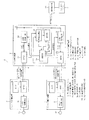
以下、本発明を、車両に搭載される電子ミラーの画像情報を伝送する電力線通信システムに適用した第1の実施形態について、図1から図8を参照して説明する。電力線通信システム1は、マスタ通信装置2と、2つのスレーブ通信装置3、4とを有する。マスタ通信装置2は、例えばインストルメントパネルの内部に組み込まれている装置である。2つのスレーブ通信装置3、4は、それぞれ車体に左右対称に取り付けられている電子ミラー装置に組み込まれている装置である。
(First embodiment)
Hereinafter, a first embodiment in which the present invention is applied to a power line communication system that transmits image information of an electronic mirror mounted on a vehicle will be described with reference to FIGS. 1 to 8. The power line communication system 1 includes a
マスタ通信装置2とスレーブ通信装置3とは、電源線5及びグランド線6を介して接続されている。マスタ通信装置2とスレーブ通信装置4とは、電源線7及びグランド線8を介して接続されている。これ以降、スレーブ通信装置3が、車体の左側(例えば左側ドア)に取り付けられている電子ミラー装置に組み込まれている装置であり、スレーブ通信装置4が、車体の右側(例えば右側ドア)に取り付けられている電子ミラー装置に組み込まれている装置であるとして説明する。
The
マスタ通信装置2は、制御部2a(制御情報生成手段、表示制御手段、第1の操作特定手段、第2の操作特定手段)と、画像処理IC(Integrated Circuit)2b(画像処理手段)と、表示部2c(表示手段)と、スレーブ通信装置3との情報の伝送用の電圧切換回路2d(電圧切換手段)及びRF(Radio Frequency)IC2e(マスタ側送受信手段)と、スレーブ通信装置4との情報の伝送用の電圧切換回路2f(電圧切換手段)及びRFIC2g(マスタ側送受信手段)とを有する。
The
制御部2aは、CPU(Central Processing Unit)、ROM(Read Only Memory)、RAM(Random Access Memory)等を有するマイクロコンピュータを主体として構成されている。制御部2aは、ROMに格納されている制御プログラムをCPUが実行し、マスタ通信装置2の動作を制御する。又、制御部2aは、ウィンカーレバー9の操作を検知する操作検知部10から操作検知信号を入力する。ユーザ(運転者)の操作によりウィンカーレバー9が中立(ニュートラル)位置から左折位置へ回動されると、制御部2aは、左折位置への回動を示す操作検知信号を操作検知部10から入力する。その後、ウィンカーレバー9が左折位置から中立位置へ復帰される(戻される)と、制御部2aは、中立位置への復帰を示す操作検知信号を操作検知部10から入力する。又、ユーザの操作によりウィンカーレバー9が中立位置から右折位置へ回動されると、右折位置への回動を示す操作検知信号を操作検知部10から入力する。その後、ウィンカーレバー9が右折位置から中立位置へ復帰される(戻される)と、制御部2aは、中立位置への復帰を示す操作検知信号を操作検知部10から入力する。
The
画像処理IC2bは、スレーブ通信装置3からRFIC2eへ伝送された画像情報を入力すると、その入力した画像情報を画像処理する。このとき、画像処理IC2bは、画像情報を画像処理することで、スレーブ通信装置3からRFIC2eへ画像情報が伝送されない期間(ブランキング期間)を特定し、その特定したブランキング期間を制御部2aへ通知する。又、画像処理IC2bは、スレーブ通信装置4からRFIC2gへ伝送された画像情報を入力すると、その入力した画像情報を画像処理する。このとき、画像処理IC2bは、画像情報を画像処理することで、スレーブ通信装置4からRFIC2gへ画像情報が伝送されない期間(ブランキング期間)を特定し、その特定したブランキング期間を制御部2aへ通知する。制御部2aは、画像処理IC2bにより画像処理された画像を表示部2cに転送させる。
When image information transmitted from the
表示部2cは、所定の画面解像度(縦横のピクセル数)の表示領域を有するLCD(Liquid Crystal Display)から構成されており、画像処理IC2bから転送された画像を表示する。又、表示部2cは、ユーザが画面上で行った操作を受付ける機能(タッチパネル機能)を有し、ユーザが指を画面上にタッチすると、そのユーザが指をタッチしたことを例えば静電容量方式により検知し、その指がタッチした位置やタッチしている時間を示す操作検知信号を制御部2aに出力する。尚、ユーザが指をタッチしたことを検知する方式としては、静電容量方式に限らず、抵抗膜方式や電磁誘導方式等の別の方式でも良い。
The
電圧切換回路2dは、車両に搭載されている車両バッテリの出力電圧(例えば12ボルト)を入力し、車両バッテリの出力電圧を所定電圧まで降圧して出力する降圧回路を有する。電圧切換回路2dは、制御部2aから入力する切換指令に基づいて出力電圧を切換える。電圧切換回路2dは、制御部2aから第1の切換指令を入力している期間では、車両バッテリの出力電圧(Vdd1)をそのまま(降圧回路により降圧せずに)RFIC2eに出力する。一方、電圧切換回路2dは、制御部2aから第2の切換指令を入力している期間では、車両バッテリの出力電圧を降圧回路により降圧した出力電圧(Vdd2(<Vdd1))をRFIC2eに出力する。電圧切換回路2gも、上記した電圧切換回路2dと同様の構成であり、制御部2aから入力する切換指令に基づいて出力電圧を切換える。尚、Vdd1、Vdd2の電位差を決定する1つの目安として消費電力や電界輻射がある。即ち、外部からの耐雑音性を考慮すると、振幅が大きいことが望ましいが、消費電力が振幅の2乗と周波数に比例して増加する点、伝送線路からの電界輻射が増加する点を考慮すると、数100mV〜数V程度とするのが一般的である。
The
RFIC2eは、電圧切換回路2dから供給されている出力電圧を電源線5の中心電位としてスレーブ通信装置3のRFIC3aからの画像情報の伝送を差動伝送で行う。即ち、RFIC2eは、電圧切換回路2dから供給されている出力電圧がVdd1の期間では、電源線5の中心電位をVdd1としてスレーブ通信装置3のRFIC3aからの画像情報の伝送を差動伝送で行う。又、RFIC2eは、電圧切換回路2dから供給されている出力電圧がVdd2の期間では、電源線5の中心電位をVdd2としてスレーブ通信装置3のRFIC3aからの画像情報の伝送を差動伝送で行う。RFIC2gも、上記したRFIC2eと同様の構成であり、電圧切換回路2gから供給されている出力電圧を電源線7の中心電位としてスレーブ通信装置4のRFIC4aからの画像情報の伝送を差動伝送で行う。
The
スレーブ通信装置3は、マスタ通信装置2との情報の伝送を行うRFIC3a(スレーブ側送受信手段)と、カメラ3b(撮像手段)と、LED駆動回路3c(駆動手段)とを有する。カメラ3bは、CCD(Charge Coupled Device)センサやCMOS(Complementary Metal-Oxide Semiconductor)センサ等を含む撮像素子であり、車両左側後方を撮像視野として撮像し、その撮像した画像情報をRFIC3aに出力する。カメラ3bの撮像視野は表示部2cの表示領域よりも広く構成されている。
The
RFIC3aは、カメラ3bから画像情報を入力すると、その入力した画像情報をマスタ通信装置2のRFIC2eへ差動伝送で伝送する。LED駆動回路3cは、左折用のウィンカー(左折方向指示器)に内蔵されているLED3d(駆動対象、発光手段)のオンオフ(点灯・消灯)を制御する。具体的には、LED駆動回路3cは、LED3dのオン期間及びオフ期間をそれぞれ計測するタイマ機能を有し、RFIC3aから入力する信号がハイレベル(1)の期間では、タイマ機能を作動させ、LED3dのオンオフを周期的に繰り返す点滅制御を行う。LED駆動回路3cは、RFIC3aから入力する信号がロウレベル(0)の期間では、タイマ機能を作動させず、LED3dのオンオフを周期的に繰り返す点滅制御を行わない。このようにスレーブ通信装置3は、カメラ3bが車両左側後方を撮像した画像情報をマスタ通信装置2へ伝送する機能と、左折用のウィンカーに内蔵されているLED3dの点滅制御を行う機能とを有する。
When the image information is input from the
スレーブ通信装置4も、上記したスレーブ通信装置3と同様の構成であり、マスタ通信装置2との情報の伝送を行うRFIC4a(スレーブ側送受信手段)と、カメラ4b(撮像手段)と、LED駆動回路4c(駆動手段)とを有する。カメラ4bは、車両右側後方を撮像視野として撮像する。カメラ4bの撮像視野も表示部2cの表示領域よりも広く構成されている。スレーブ通信装置4は、カメラ4bが車両右側後方を撮像した画像情報をマスタ通信装置2へ伝送する機能と、右折用のウィンカーに内蔵されているLED4d(駆動対象、発光手段)の点滅制御を行う機能とを有する。
The slave communication device 4 has the same configuration as that of the
次に、マスタ通信装置2のRFIC2e、2gとスレーブ通信装置3のRFIC3a及びスレーブ通信装置4のRFIC4aについて説明する。尚、マスタ通信装置2のRFIC2eとスレーブ通信装置3のRFIC3aの関係と、マスタ通信装置2のRFIC2gとスレーブ通信装置4のRFIC4aの関係とは同じであるので、これ以降、マスタ通信装置2のRFIC2eとスレーブ通信装置3のRFIC3aの関係を代表して説明する。
Next, the
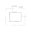
図2に示すように、スレーブ通信装置3のRFIC3aはドライバ11を有し、マスタ通信装置2のRFIC2eはレシーバ12を有する。ドライバ11及びレシーバ12は、それぞれ差動伝送に対応する構成である。ドライバ11の送受信端子は、それぞれカップリングキャパシタ13、14を介して伝送線路17、18に接続されている。レシーバ12の送受信端子は、それぞれカップリングキャパシタ15、16を介して伝送線路17、18に接続されている。カップリングキャパシタ13と伝送線路17との接続点及びカップリングキャパシタ15と伝送線路17との接続点は、それぞれインダクタ19、20を介して電源電圧側に接続されている。カップリングキャパシタ14と伝送線路18との接続点及びカップリングキャパシタ16と伝送線路18との接続点は、それぞれインダクタ21、22を介して接地側に接続されている。電源電圧としては、上記したように電圧切換回路2dからの出力電圧であるVdd1又はVdd2が選択的に供給される。
As shown in FIG. 2, the
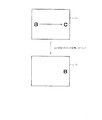
上記した構成では、図3に示すように、スレーブ通信装置3(RFIC3aのドライバ11)からマスタ通信装置2(RFIC2eのレシーバ12)への画像情報(「1」、「0」からなるビット列)の伝送を差動伝送で行う。これにより、カメラ3bが撮像した画像情報がスレーブ通信装置3からマスタ通信装置2へ伝送され、その画像情報が画像処理IC2bで画像処理された画像が表示部2cに表示される。
In the above-described configuration, as shown in FIG. 3, image information (a bit string consisting of “1” and “0”) from the slave communication device 3 (
マスタ通信装置2(RFIC2eのレシーバ12)からスレーブ通信装置3(RFIC3aのドライバ11)へのウィンカー情報(「1」、「0」)の伝送を電源線5への供給電圧を切換えることで行う。即ち、マスタ装置2において、制御部2aは、ウィンカーレバー9が中立位置であることを検知している期間では、第2の切換指令を電圧切換回路2dに出力する。電圧切換回路2dは、制御部2aから第2の切換指令を入力すると、Vdd2をRFIC2eに供給する。即ち、RFIC2eのレシーバ12にはVdd2が供給され、RFIC3aのドライバ11にも伝送線路17を介してVdd2が供給される。このとき、画像情報がスレーブ通信装置3からマスタ通信装置2へVdd2を中心電位とする差動伝送により伝送される。又、マスタ通信装置2からスレーブ通信装置3へは、電源線5への供給電圧がVdd2であることにより、ウィンカー情報の「0」が伝送される。このようにしてウィンカー情報の「0」がマスタ通信装置2からスレーブ通信装置3へ伝送されている期間では、LED駆動回路3cは、LED3dのオンオフを周期的に繰り返す点滅制御を行わない。
The blinker information (“1”, “0”) is transmitted from the master communication device 2 (
一方、制御部2aは、ウィンカーレバー9が中立位置から左折位置に回動され、左折位置であることを検知している期間では、第1の切換指令を電圧切換回路2dに出力する。電圧切換回路2dは、制御部2aから第1の切換指令を入力すると、Vdd1をRFIC2eに供給する。即ち、RFIC2eのレシーバ12にはVdd1が供給され、RFIC3aのドライバ11にも伝送線路17を介してVdd1が供給される。このとき、画像情報がスレーブ通信装置3からマスタ通信装置2へVdd1を中心電位とする差動伝送により伝送される。又、マスタ通信装置2からスレーブ通信装置3へは、電源線5への供給電圧がVdd1であることにより、ウィンカー情報の「1」が伝送される。このようにしてウィンカー情報の「1」がマスタ通信装置2からスレーブ通信装置3へ伝送されている期間では、LED駆動回路3cは、図4に示すように、LED3dのオンオフを周期的に繰り返す点滅制御を行う。
On the other hand, the
以上により、画像情報をスレーブ通信装置3からマスタ通信装置2へ伝送すると同時に、ウィンカー情報をマスタ通信装置2からスレーブ通信装置3へ伝送し、全二重通信を行う。尚、画像情報の伝送とウィンカー情報の伝送とは非同期である。又、制御部2aは、ウィンカーレバー9が中立位置から左折位置に回動されたタイミング以降の最初の画像処理IC2bからブランキング期間が通知されたタイミングで、第1の切換指令を電圧切換回路2dに出力しても良い。又、制御部2aは、ウィンカーレバー9が左折位置から中立位置に復帰されたタイミング以降の最初の画像処理IC2bからブランキング期間が通知されたタイミングで、第2の切換指令を電圧切換回路2dに出力しても良い。即ち、電源線5への供給電圧をVdd1とVdd2との間で切換える際には、信号の直流成分が変化することで、スレーブ通信装置3からマスタ通信装置2へ伝送される画像情報にビットエラーが発生し、画像にノイズが重なる等のシステム全体として不具合が発生する可能性がある。このような状況を未然に回避するために、ビットエラーが発生してもシステム全体に影響が及ぼされないブランキング期間を利用する。画像情報が伝送されていないブランキング期間で、電源線5への供給電圧をVdd1とVdd2との間で切換えることで、画像にノイズが重なる等のシステム全体として不具合が発生する可能性を排除することができる。
As described above, the image information is transmitted from the
次に、マスタ通信装置2が行う画像の表示制御について説明する。マスタ通信装置2において、制御部2aは、表示部2cから入力する操作検知信号及び操作検知部10から入力する操作検知信号に基づいて画像の表示態様を変更する。即ち、制御部2aは、図5に示すようにカメラ3b、4bの撮像視野が表示部2cの表示領域よりも広く、スレーブ通信装置3、4からマスタ通信装置2へ伝送される画像情報に含まれるデータ量が表示部2cの表示領域に相当するデータ量よりも大きいことを利用し、画像の表示態様を変更する。
Next, image display control performed by the
制御部2aは、ユーザが指を画面上にタッチし、表示部2cから操作検知信号を入力すると、その入力した操作検知信号に基づいて画像の表示態様を変更する。具体的に説明すると、制御部2aは、図6に示すように、ユーザが画面上で「A」の位置をタッチしたと判定すると、「A」の位置を中心として画像を拡大表示させる。又、制御部2aは、図7に示すように、ユーザが画面上で「B」の位置から「C」の位置までドラッグした(指を画面上にタッチしたまま移動した)と判定すると、その操作量に応じて画像を移動表示させる。
When the user touches a finger on the screen and inputs an operation detection signal from the
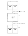
又、制御部2aは、ユーザがウィンカーレバー9を操作し、操作検知部10から操作検知信号を入力すると、その入力した操作検知信号に基づいて画像の表示態様を変更する。具体的に説明すると、制御部2aは、図8に示すように、ウィンカーレバー9が中立位置であるときに、カメラ3bが撮像した画像を表示部2cの表示領域の左半部に表示させると共に、カメラ4bが撮像した画像を表示部2cの表示領域の右半部に表示させる。この状態から、ウィンカーレバー9が中立位置から左折位置へ回動されると、制御部2aは、カメラ3bが撮像した画像を表示部2cの表示領域の全体に表示させると共に、カメラ4bが撮像した画像の表示を停止する。そして、ウィンカーレバー9が左折位置から中立位置へ復帰される(戻される)と、制御部2aは、ウィンカーレバー9が中立位置から左折位置へ回動される前の表示態様に戻し、カメラ3bが撮像した画像を表示部2cの表示領域の左半部に表示させると共に、カメラ4bが撮像した画像を表示部2cの表示領域の右半部に表示させる。制御部2aは、ウィンカーレバー9が中立位置から右折位置へ回動され、右折位置から中立位置へ復帰された(戻された)ときも同様にして画像の表示態様を変更する。
In addition, when the user operates the
以上に説明したように第1の実施形態によれば、次に示す効果を得ることができる。
スレーブ通信装置3、4からマスタ通信装置2への画像情報の伝送を差動伝送で行い、マスタ通信装置2からスレーブ通信装置3、4へのウィンカー情報の伝送を電源線5、7への供給電圧を切換えることで行うようにした。これにより、システムとして通信線の増設を回避することができながらも、スレーブ通信装置3、4からマスタ通信装置2への画像情報の伝送と、マスタ通信装置2からスレーブ通信装置3、4へのウィンカー情報の伝送とを同時に行うことができ、全二重通信を行うことができる。
As described above, according to the first embodiment, the following effects can be obtained.
Transmission of image information from the
又、画像情報が伝送されていないブランキング期間で、電源線5、7への供給電圧をVdd1とVdd2との間で切換えるようにした。これにより、画像にノイズが重なる等のシステム全体として不具合が発生する可能性を排除することができ、システム全体として安定な動作を保証することができる。又、電源線5、7への供給電圧の1つとして車両バッテリの出力電圧をそのまま供給するようにした。これにより、電源線5、7への供給電圧を切換える電圧切換回路2d、2fの構成を簡素化することができる。
Further, the supply voltage to the power supply lines 5 and 7 is switched between Vdd1 and Vdd2 during the blanking period during which no image information is transmitted. As a result, it is possible to eliminate the possibility of a problem occurring in the entire system, such as noise on the image, and to ensure a stable operation as the entire system. Further, the output voltage of the vehicle battery is supplied as it is as one of the supply voltages to the power lines 5 and 7. Thereby, the structure of the
又、LED駆動回路3c、4cがLED3d、4dのオン期間及びオフ期間をそれぞれ計測するタイマ機能を有し、LED駆動回路3c、4cがLED3d、4dのオンオフを周期的に繰り返す点滅制御を行うようにした。これにより、ウィンカー情報をマスタ通信装置2からスレーブ通信装置3、4へ伝送してLED3d、4dを点滅させる場合に、点滅期間の先頭と末尾のみのタイミングで電源線5、7への供給電圧を切換えれば良く、電源線5、7への供給電圧を切換える頻度を抑制することができる。電源線5、7への供給電圧を切換える頻度を極力抑制することで、耐雑音性を高めることができる。
In addition, the
又、カメラ3b、4bの撮像視野が表示部2cの表示領域よりも広いことを利用し、ユーザが指を画面上で操作すると、そのユーザの操作に基づいて画像の表示態様を変更するようにした。これにより、マスタ通信装置2からスレーブ通信装置3、4へカメラの撮像方向の変更を指示する信号を伝送しなくとも、所望の方向の画像を表示させることができる。ユーザがウィンカーレバー9を操作すると、そのユーザの操作に基づいて画像の表示態様を変更するようにし、ウィンカーレバー9が回動された方向の画像が表示部2cの表示領域の全体に表示されるようにした。これにより、ユーザが画像の表示態様を変更する操作をしなくとも、ウィンカーレバー9が回動された方向の画像を自動的に表示させることができ、運転支援を適切に行うことができる。
Further, using the fact that the imaging field of view of the
(第2の実施形態)
次に、本発明の第2の実施形態について、図9及び図10を参照して説明する。尚、上記した第1の実施形態と同一部分については説明を省略し、異なる部分について説明する。第1の実施形態は、スレーブ通信装置3、4のLED駆動回路3c、4cがLED3d、4dのオン期間及びオフ期間をそれぞれ計測するタイマ機能を有する構成であるが、第2の実施形態は、マスタ通信装置2の制御部2aがLED3d、4dのオン期間及びオフ期間をそれぞれ計測するタイマ機能を有する構成である。
(Second Embodiment)
Next, a second embodiment of the present invention will be described with reference to FIGS. In addition, description is abbreviate | omitted about the same part as above-mentioned 1st Embodiment, and a different part is demonstrated. In the first embodiment, the
即ち、制御部2aは、ウィンカーレバー9が中立位置から左折位置に回動され、左折位置であることを検知している期間では、タイマ機能を作動させることで、第1の切換指令と第2の切換指令とを電圧切換回路2dに交互に出力する。電圧切換回路2dは、制御部2aから第1の切換指令と第2の切換指令とを交互に入力すると、Vdd1とVdd2とをRFIC2eに交互に供給する。このとき、スレーブ通信装置3からマスタ通信装置2へは、画像情報がVdd1を中心電位とする差動伝送とVdd2を中心電位とする差動伝送とが切換えられて伝送される。このようにしてウィンカー情報の「0」、「1」がマスタ通信装置2からスレーブ通信装置3へ伝送される。LED駆動回路3cは、RFIC3aから入力する信号がハイレベル(1)の期間では、LED3dをオンさせ、RFIC3aから入力する信号がロウレベル(0)の期間では、LED3dをオフさせる。第2の実施形態においても、上記した第1の実施形態と同様の作用効果を得ることができ、全二重通信を行うことができる。
That is, the
(その他の実施形態)
本発明は、上記した実施形態にのみ限定されるものではなく、以下のように変形又は拡張することができる。
車両に搭載される電子ミラーの画像情報を伝送する電力線通信システムに限らず、車両に搭載される他の電力線通信システムに適用することも可能である。又、車両とは別の対象に搭載される電力線通信システムに適用することも可能である。
車両バッテリの出力電圧をVdd1とし、車両バッテリの出力電圧を降圧回路により降圧した出力電圧をVdd2とする構成を例示したが、車両バッテリの出力電圧を別々の降圧回路により降圧した出力電圧をそれぞれVdd1、Vdd2としても良い。
(Other embodiments)
The present invention is not limited to the above-described embodiment, and can be modified or expanded as follows.
The present invention is not limited to a power line communication system that transmits image information of an electronic mirror mounted on a vehicle, but can be applied to other power line communication systems mounted on a vehicle. Moreover, it is also possible to apply to the power line communication system mounted in the object different from a vehicle.
Although the configuration in which the output voltage of the vehicle battery is Vdd1 and the output voltage obtained by stepping down the output voltage of the vehicle battery by the step-down circuit is illustrated as Vdd2, the output voltage obtained by stepping down the output voltage of the vehicle battery by a separate step-down circuit is illustrated as Vdd1. , Vdd2 may be used.
LED3d、4dのオンオフを制御するウィンカー情報がマスタ通信装置2からスレーブ通信装置3、4へ伝送される構成を例示したが、他の情報がマスタ通信装置2からスレーブ通信装置3、4へ伝送される構成でも良い。例えばカメラ3b、4bが撮像する際の補助光源のオンオフを制御する情報やカメラ3b、4bの曇り防止機能のオンオフを制御する情報等がマスタ通信装置2からスレーブ通信装置3、4へ伝送される構成でも良い。
カメラ3b、4bが撮像した撮像情報がスレーブ通信装置3、4からマスタ通信装置2へ伝送される構成を例示したが、撮像情報に加えてLED3d、4dのオンオフ情報(駆動対象の動作状態を示す動作情報)もスレーブ通信装置3、4からマスタ通信装置2へ伝送される構成でも良い。このように構成すれば、マスタ通信装置2において、LED3d、4dのオンオフに連動した処理(例えば表示処理等)が可能となる。又、LED3d、4dのオンオフ情報がユーザに報知されるように構成すれば、LED3d、4dの点滅動作が正常に行われているか否かをユーザが確認することができる。
The blinker information for controlling on / off of the
Although the configuration in which the imaging information captured by the
マスタ通信装置2において、電源線5、7への供給電圧をVdd1、Vdd2の2段階に切換える構成を例示したが、3段階以上に切換えても良い。Vdd1、Vdd2の2段階に切換える構成では、Vdd1に「1」を割当て、Vdd2に「0」を割当てるに過ぎないが、例えばVdd1〜Vdd4の4段階に切換える構成では、Vdd1に「11」を割当て、Vdd2に「10」を割当て、Vdd3に「01」を割当て、Vdd4に「00」を割当てることで、マスタ通信装置2からスレーブ通信装置3への伝送速度を高めることができる。又、例えばVdd1〜Vdd4の4段階に切換える構成では、Vdd1とVdd2をマスタ通信装置2とスレーブ通信装置3との間の情報の伝送で用い、Vdd3とVdd4をマスタ通信装置2とスレーブ通信装置4との間の情報の伝送で用いることで、マスタ通信装置2が1つのRFICを有し、スレーブ通信装置3、4が共通で1つのRFICを有する構成が可能となる。又、電圧切換回路2d、2fに昇圧回路を設けても良く、降圧回路と昇圧回路を併用して設けても良い。
In the
マスタ通信装置2が行う画像の表示制御としては、ユーザが画面上でドラッグした場合に加え、フリック(指を画面上で軽く払う)、ピンチイン(2本の指を画面上にタッチしたまま指同士の間隔を狭める)、ピンチアウト(2本の指を画面上にタッチしたまま指同士の間隔を広める)等の操作を行った場合にも、そのユーザの操作に基づいて画像の表示態様を変更するようにしても良い。即ち、ユーザが画面上でフリックした場合には、その操作量に応じて画像を移動表示させても良いし、ピンチインした場合には、その操作量に応じて画像を縮小表示させても良いし(縮尺を小さくする)、ピンチアウトした場合には、その操作量に応じて画像を拡大表示させても良い(縮尺を大きくする)。
The image display control performed by the
ウィンカーレバー9が中立位置であるときに、カメラ3bが撮像した画像を表示部2cの表示領域の左半部に表示すると共に、カメラ4bが撮像した画像を表示部2cの表示領域の右半部に表示する構成を例示したが、カメラ3bが撮像した画像を表示する表示部と、カメラ3bが撮像した画像を表示する表示部とが別々の構成でも良い。例えばカメラ3bが撮像した画像を表示する表示部が左側のドアに設置されると共に、カメラ4bが撮像した画像を表示する表示部が右側のドアに設置される構成でも良い。
When the
図面中、1は電力線通信システム、2はマスタ通信装置、2aは制御部(制御情報生成手段、表示制御手段、第1の操作特定手段、第2の操作特定手段)、2bは画像処理IC(画像処理手段)、2cは表示部(表示手段)、2d、2fは電圧切換回路(電圧切換手段)、2e、2gはRFIC(マスタ側送受信手段)、3、4はスレーブ通信装置、3a、4aはRFIC(スレーブ側送受信手段)、3b、4bはカメラ(撮像手段)、3c、4cはLED駆動回路(駆動手段)、3d、4dはLED(駆動対象、発光手段)、5、7は電源線、6、8はグランド線、9はウィンカーレバー(操作機器)である。 In the drawings, 1 is a power line communication system, 2 is a master communication device, 2a is a control unit (control information generating means, display control means, first operation specifying means, second operation specifying means), and 2b is an image processing IC ( Image processing means), 2c is a display unit (display means), 2d and 2f are voltage switching circuits (voltage switching means), 2e and 2g are RFICs (master side transmission / reception means), 3 and 4 are slave communication devices, 3a and 4a Are RFIC (slave-side transmission / reception means), 3b and 4b are cameras (imaging means), 3c and 4c are LED drive circuits (drive means), 3d and 4d are LEDs (drive objects and light emission means), and 5 and 7 are power lines. , 6 and 8 are ground wires, and 9 is a winker lever (operating device).
Claims (13)
前記電源線への供給電圧を複数段階に切換える電圧切換手段(2d、2f)を備え、少なくとも前記スレーブ側送受信手段から前記マスタ側送受信手段へ情報が差動伝送で伝送されている期間で前記電源線への供給電圧を前記電圧切換手段により複数段階に切換えることで、前記スレーブ側送受信手段から前記マスタ側送受信手段への情報の伝送を行うと同時に、前記マスタ側送受信手段から前記スレーブ側送受信手段への情報の伝送を行い、前記スレーブ側送受信手段と前記マスタ側送受信手段との間で全二重通信を行うことを特徴とする電力線通信システム。 The master side transmission / reception means (2e, 2g) of the master communication device (2) and the slave side transmission / reception means (3a, 4a) of the slave communication device (3, 4) are connected to the power supply line (5, 7) and the ground line (6, are connected via 8), in the power line communication system for performing from the slave side transmitting and receiving means the transmission of information to the master side transmitting and receiving means by the differential transmission,
Voltage switching means (2d, 2f) for switching the supply voltage to the power supply line in a plurality of stages, and at least the power supply in a period in which information is transmitted from the slave side transmission / reception means to the master side transmission / reception means by differential transmission By switching the supply voltage to the line in a plurality of stages by the voltage switching means , information is transmitted from the slave side transmission / reception means to the master side transmission / reception means , and at the same time, from the master side transmission / reception means to the slave side transmission / reception means There line transmission of information to, the power line communication system, wherein line Ukoto full duplex communication between said master-side transmitting and receiving means and said slave side transmitting and receiving means.
前記電圧切換手段は、前記スレーブ側送受信手段から前記マスタ側送受信手段へ情報が伝送されていない期間で、前記電源線への供給電圧を複数段階に切換えることを特徴とする電力線通信システム。 In the power line communication system according to claim 1,
The power line communication system characterized in that the voltage switching means switches the supply voltage to the power line in a plurality of stages during a period in which information is not transmitted from the slave side transmission / reception means to the master side transmission / reception means.
前記電圧切換手段は、前記電源線への供給電圧の1つとして車両バッテリの出力電圧を含むことを特徴とする電力線通信システム。 In the power line communication system according to claim 1 or 2,
The power line communication system, wherein the voltage switching means includes an output voltage of a vehicle battery as one of supply voltages to the power line.
駆動対象(3d、4d)の制御情報を生成する制御情報生成手段(2a)が前記マスタ通信装置に設けられると共に、前記駆動対象の動作を制御する駆動手段(3c、4c)が前記スレーブ通信装置に設けられ、
前記マスタ側送受信手段は、前記制御情報生成手段により生成された制御情報を前記スレーブ側送受信手段へ伝送し、
前記駆動手段は、前記マスタ側送受信手段から前記スレーブ側送受信手段へ伝送された制御情報に基づいて前記駆動対象の動作を制御することを特徴とする電力線通信システム。 In the power line communication system according to any one of claims 1 to 3,
Control information generating means (2a) for generating control information of the drive target (3d, 4d) is provided in the master communication device, and drive means (3c, 4c) for controlling the operation of the drive target is the slave communication device. Provided in
The master side transmitting / receiving means transmits the control information generated by the control information generating means to the slave side transmitting / receiving means,
The power line communication system characterized in that the drive means controls the operation of the drive target based on control information transmitted from the master side transmission / reception means to the slave side transmission / reception means.
前記制御情報生成手段は、前記駆動対象のオンオフ切換期間の有効・無効を示す制御情報を生成し、
前記駆動手段は、前記駆動対象のオンオフ切換期間が有効であることを示す制御情報が前記マスタ側送受信手段から前記スレーブ側送受信手段へ伝送されている期間で前記駆動対象のオンオフを切換制御することを特徴とする電力線通信システム。 The power line communication system according to claim 4,
The control information generating means generates control information indicating validity / invalidity of the on / off switching period of the drive target,
The driving means performs switching control of on / off of the driving target during a period in which control information indicating that the on / off switching period of the driving target is valid is transmitted from the master side transmitting / receiving means to the slave side transmitting / receiving means. A power line communication system.
前記制御情報生成手段は、前記駆動対象のオンオフを示す制御情報を生成し、
前記駆動手段は、前記駆動対象のオンを示す制御情報が前記マスタ側送受信手段から前記スレーブ側送受信手段へ伝送されている期間で前記駆動対象をオンに切換制御し、前記駆動対象のオフを示す制御情報が前記マスタ側送受信手段から前記スレーブ側送受信手段へ伝送されている期間で前記駆動対象をオフに切換制御することを特徴とする電力線通信システム。 The power line communication system according to claim 4,
The control information generating means generates control information indicating on / off of the drive target,
The drive means controls the drive object to be turned on during a period in which control information indicating that the drive object is on is transmitted from the master side transmission / reception means to the slave side transmission / reception means, and indicates that the drive object is off. A power line communication system, wherein the drive target is switched off during a period in which control information is transmitted from the master side transmitting / receiving means to the slave side transmitting / receiving means.
前記駆動対象は、車両のウィンカー構成する発光手段(3d、4d)であり、
前記制御情報生成手段は、制御情報として前記発光手段の点灯・消灯を示すウィンカー情報を生成し、
前記駆動手段は、前記発光手段の点灯・消灯の動作を制御することを特徴とする電力線通信システム。 In the power line communication system according to any one of claims 4 to 6,
The driving object is light emitting means (3d, 4d) constituting a winker of the vehicle,
The control information generating means generates winker information indicating turning on / off of the light emitting means as control information,
The power line communication system characterized in that the driving means controls the operation of turning on and off the light emitting means.
前記スレーブ側送受信手段は、前記駆動対象の動作状態を示す動作情報を前記マスタ側送受信手段へ伝送することを特徴とする電力線通信システム。 In the power line communication system according to any one of claims 4 to 7,
The power transmission / reception system according to claim 1, wherein the slave side transmission / reception means transmits operation information indicating an operation state of the drive target to the master side transmission / reception means.
撮像手段(3b、4b)が前記スレーブ通信装置に設けられると共に、画像処理手段(2b)が前記マスタ通信装置に設けられ、
前記スレーブ側送受信手段は、前記撮像手段により撮像された画像情報を前記マスタ側送受信手段へ伝送し、
前記マスタ側送受信手段は、前記スレーブ側送受信手段から伝送された画像情報を前記画像処理手段により画像処理することを特徴とする電力線通信システム。 In the power line communication system according to any one of claims 1 to 8,
Imaging means (3b, 4b) is provided in the slave communication device, and image processing means (2b) is provided in the master communication device,
The slave side transmitting / receiving means transmits image information captured by the imaging means to the master side transmitting / receiving means,
The power line communication system according to claim 1, wherein the master side transmission / reception means performs image processing on the image information transmitted from the slave side transmission / reception means by the image processing means.
所定の表示領域を有する表示手段(2c)と、前記画像情報が前記画像処理手段により画像処理された画像を前記表示手段に表示させる表示制御手段(2a)と、が前記マスタ通信装置に設けられていることを特徴とする電力線通信システム。 The power line communication system according to claim 9, wherein
A display means (2c) having a predetermined display area and a display control means (2a) for causing the display means to display an image obtained by processing the image information by the image processing means are provided in the master communication device. A power line communication system.
ユーザが前記表示手段の画面上で行った操作を特定する第1の操作特定手段(2a)を備え、
前記表示制御手段は、前記第1の操作特定手段により特定された操作に基づいて画像の表示態様を変更することを特徴とする電力線通信システム。 The power line communication system according to claim 10, wherein
A first operation specifying means (2a) for specifying an operation performed by the user on the screen of the display means;
The power control system, wherein the display control unit changes an image display mode based on the operation specified by the first operation specifying unit.
ユーザが操作機器(9)に対して行った操作を特定する第2の操作特定手段(2a)を備え、
前記表示制御手段は、前記第2の操作特定手段により特定された操作に基づいて画像の表示態様を変更することを特徴とする電力線通信システム。 The power line communication system according to claim 10 or 11,
A second operation specifying means (2a) for specifying an operation performed by the user on the operating device (9);
The power control system, wherein the display control unit changes an image display mode based on the operation specified by the second operation specifying unit.
前記電源線への供給電圧を複数段階に切換える電圧切換手段(2d、2f)を備え、少なくとも前記スレーブ側送受信手段から前記マスタ側送受信手段へ情報が差動伝送で伝送されている期間で前記電源線への供給電圧を前記電圧切換手段により複数段階に切換えることで、前記スレーブ側送受信手段から前記マスタ側送受信手段への情報の伝送を行うと同時に、前記マスタ側送受信手段から前記スレーブ側送受信手段への情報の伝送を行い、前記スレーブ側送受信手段と前記マスタ側送受信手段との間で全二重通信を行うことを特徴とするマスタ通信装置。 Master side transmission / reception means (2e, 2g) connected to the slave side transmission / reception means (3a, 4a) of the slave communication device (3, 4) via the power lines (5, 7) and the ground lines (6, 8). A master communication device (2) that performs differential transmission of information from the slave-side transmission / reception means to the master-side transmission / reception means,
Voltage switching means (2d, 2f) for switching the supply voltage to the power supply line in a plurality of stages, and at least the power supply in a period in which information is transmitted from the slave side transmission / reception means to the master side transmission / reception means by differential transmission By switching the supply voltage to the line in a plurality of stages by the voltage switching means , information is transmitted from the slave side transmission / reception means to the master side transmission / reception means , and at the same time, from the master side transmission / reception means to the slave side transmission / reception means There line transmission of information to the master communication apparatus, wherein the line Ukoto full duplex communication between said master-side transmitting and receiving means and said slave side transmitting and receiving means.
Priority Applications (2)
| Application Number | Priority Date | Filing Date | Title |
|---|---|---|---|
| JP2014131348A JP6414397B2 (en) | 2014-06-26 | 2014-06-26 | Power line communication system and master communication device |
| US14/748,514 US9755861B2 (en) | 2014-06-26 | 2015-06-24 | Power line communication system and master communication device |
Applications Claiming Priority (1)
| Application Number | Priority Date | Filing Date | Title |
|---|---|---|---|
| JP2014131348A JP6414397B2 (en) | 2014-06-26 | 2014-06-26 | Power line communication system and master communication device |
Publications (2)
| Publication Number | Publication Date |
|---|---|
| JP2016010116A JP2016010116A (en) | 2016-01-18 |
| JP6414397B2 true JP6414397B2 (en) | 2018-10-31 |
Family
ID=54931714
Family Applications (1)
| Application Number | Title | Priority Date | Filing Date |
|---|---|---|---|
| JP2014131348A Expired - Fee Related JP6414397B2 (en) | 2014-06-26 | 2014-06-26 | Power line communication system and master communication device |
Country Status (2)
| Country | Link |
|---|---|
| US (1) | US9755861B2 (en) |
| JP (1) | JP6414397B2 (en) |
Family Cites Families (5)
| Publication number | Priority date | Publication date | Assignee | Title |
|---|---|---|---|---|
| JP3675740B2 (en) * | 2001-07-11 | 2005-07-27 | 株式会社デンソー | Communication device having power supply type power supply type communication line |
| JP2006067421A (en) * | 2004-08-30 | 2006-03-09 | Auto Network Gijutsu Kenkyusho:Kk | Signal transmitter, camera, connector device and in-vehicle communication system |
| JP2007174429A (en) | 2005-12-22 | 2007-07-05 | Matsushita Electric Works Ltd | Wiring system |
| US8212379B2 (en) * | 2009-03-06 | 2012-07-03 | Amperion, Inc. | Station communications over electrical transmission lines |
| WO2013164670A1 (en) * | 2012-02-15 | 2013-11-07 | Lumenpulse Lighting Inc. | Led lighting systems |
-
2014
- 2014-06-26 JP JP2014131348A patent/JP6414397B2/en not_active Expired - Fee Related
-
2015
- 2015-06-24 US US14/748,514 patent/US9755861B2/en active Active
Also Published As
| Publication number | Publication date |
|---|---|
| US20150381391A1 (en) | 2015-12-31 |
| JP2016010116A (en) | 2016-01-18 |
| US9755861B2 (en) | 2017-09-05 |
Similar Documents
| Publication | Publication Date | Title |
|---|---|---|
| US9346358B2 (en) | Vehicle control apparatus | |
| CN103513813B (en) | Display device with integrated touch screen | |
| US9195390B2 (en) | Method for controlling display of vehicular image by touch panel and vehicular image system thereof | |
| CN102450007A (en) | Image processing apparatus, electronic apparatus, and image processing method | |
| CN110326285B (en) | Image sensor and control system | |
| US9563582B2 (en) | Modular device, system, and method for reconfigurable data distribution | |
| CN103970346A (en) | Semiconductor device | |
| JP5924370B2 (en) | Video display device, video switching device, and video display method | |
| US20150274176A1 (en) | Moving amount derivation apparatus | |
| US10455143B2 (en) | Vehicle display with view control | |
| CN112416159A (en) | Electronic circuit with display driving, touch sensing and fingerprint sensing functions | |
| CN104183222A (en) | Display device | |
| JP2016130952A (en) | Electronic apparatus, control method of electronic apparatus, program, and storage medium | |
| CN110047448B (en) | Touch panel control device, touch panel control method, and input display device | |
| JP7078347B2 (en) | Sensor device | |
| JP6414397B2 (en) | Power line communication system and master communication device | |
| US10623610B2 (en) | Display processing device and display processing method | |
| JP2008141622A (en) | Vehicle surrounding information display apparatus | |
| US10037595B2 (en) | Image processing device and image processing method | |
| CN106683636B (en) | Suitable for vehicle-mounted high-definition multimedia interface and its application | |
| CN102314267B (en) | A kind of method that realizes of wireless infrared interaction and device | |
| CN110383826B (en) | Image sensor and transmission system | |
| JP6410767B2 (en) | Driver integrated circuit, driving method, and touch display system | |
| US10271002B2 (en) | Image display apparatus, external device, image display method, and image display system | |
| CN112882673A (en) | Collage display system and data processing method thereof |
Legal Events
| Date | Code | Title | Description |
|---|---|---|---|
| A621 | Written request for application examination |
Free format text: JAPANESE INTERMEDIATE CODE: A621 Effective date: 20170228 |
|
| A977 | Report on retrieval |
Free format text: JAPANESE INTERMEDIATE CODE: A971007 Effective date: 20171212 |
|
| A131 | Notification of reasons for refusal |
Free format text: JAPANESE INTERMEDIATE CODE: A131 Effective date: 20180130 |
|
| A521 | Request for written amendment filed |
Free format text: JAPANESE INTERMEDIATE CODE: A523 Effective date: 20180323 |
|
| TRDD | Decision of grant or rejection written | ||
| A01 | Written decision to grant a patent or to grant a registration (utility model) |
Free format text: JAPANESE INTERMEDIATE CODE: A01 Effective date: 20180905 |
|
| A61 | First payment of annual fees (during grant procedure) |
Free format text: JAPANESE INTERMEDIATE CODE: A61 Effective date: 20180918 |
|
| R151 | Written notification of patent or utility model registration |
Ref document number: 6414397 Country of ref document: JP Free format text: JAPANESE INTERMEDIATE CODE: R151 |
|
| LAPS | Cancellation because of no payment of annual fees |